intellistation types and 6231
TRANSCRIPT

Hardware Maintenance Manual
IBM IntelliStation Types 6849 and 6231
���


Hardware Maintenance Manual
IBM IntelliStation Types 6849 and 6231
���

Notes
Before using this information and the product it supports, be sure to read the general information under “Notices” on page
133.
Third Edition (January 2004)
The following paragraph does not apply to the United Kingdom or any country where such provisions are
inconsistent with local law.
INTERNATIONAL BUSINESS MACHINES CORPORATION PROVIDES THIS PUBLICATION ″AS IS″ WITHOUT
WARRANTY OF ANY KIND, EITHER EXPRESS OR IMPLIED, INCLUDING, BUT NOT LIMITED TO, THE IMPLIED
WARRANTIES OF MERCHANTABILITY OR FITNESS FOR A PARTICULAR PURPOSE. Some states do not allow
disclaimer of express or implied warranties in certain transactions, therefore, this statement may not apply to you.
This publication could include technical inaccuracies or typographical errors. Changes are periodically made to the
information herein; these changes will be incorporated in new editions of the publication. IBM may make
improvements and/or changes in the product(s) and/or the program(s) described in this publication at any time.
This publication was developed for products and services offered in the United States of America. IBM may not offer
the products, services, or features discussed in this document in other countries, and the information is subject to
change without notice. Consult your local IBM representative for information on the products, services, and features
available in your area.
Requests for technical information about IBM products should be made to your IBM reseller or IBM marketing
representative.
© Copyright International Business Machines Corporation 2000, 2001. All rights reserved.
US Government Users Restricted Rights – Use, duplication or disclosure restricted by GSA ADP Schedule Contract
with IBM Corp.

About this manual
This manual contains diagnostic information, a Symptom-to-FRU index, service
information, error indications, and configuration information for the IBM IntelliStation
Type 6849 and 6231 computers.
Attention: This manual is intended for trained servicers who are familiar with IBM
PC computer products.
Important safety information
Be sure to read all caution and danger statements in this book before performing
any of the instructions.
Leia todas as instruções de cuidado e perigo antes de executar qualquer operação.
Prenez connaissance de toutes les consignes de type Attention et
Danger avant de procéder aux opérations décrites par les instructions.
Lesen Sie alle Sicherheitshinweise, bevor Sie eine Anweisung ausführen.
© Copyright IBM Corp. 2000, 2001 iii

Accertarsi di leggere tutti gli avvisi di attenzione e di pericolo prima di effettuare
qualsiasi operazione.
Lea atentamente todas las declaraciones de precaución y peligro ante de llevar a
cabo cualquier operación.
Online support
Use the World Wide Web (WWW) to download Diagnostic, BIOS Flash, and Device
Driver files, and Documents.
The Web address is:
http://www.ibm.com/pc/support
iv Hardware Maintenance Manual: IBM IntelliStation Types 6849 and 6231

Contents
About this manual . . . . . . . . . . . . . . . . . . . . . . . iii
Important safety information . . . . . . . . . . . . . . . . . . . . iii
Online support . . . . . . . . . . . . . . . . . . . . . . . . . iv
Chapter 1. General checkout . . . . . . . . . . . . . . . . . . . 1
Chapter 2. General information . . . . . . . . . . . . . . . . . . . 3
Introducing the Intellistation M Pro . . . . . . . . . . . . . . . . . . 3
Features and specifications . . . . . . . . . . . . . . . . . . . . . 4
Chapter 3. Diagnostics . . . . . . . . . . . . . . . . . . . . . . 5
POST . . . . . . . . . . . . . . . . . . . . . . . . . . . . . 5
POST beep code descriptions . . . . . . . . . . . . . . . . . . . 5
Small computer system interface messages (some models) . . . . . . . . . 5
IBM Enhanced Diagnostics . . . . . . . . . . . . . . . . . . . . . 6
Text messages . . . . . . . . . . . . . . . . . . . . . . . . 7
Starting the diagnostic programs . . . . . . . . . . . . . . . . . . 7
Using the Device Driver and IBM Enhanced Diagnostics CD . . . . . . 8
Downloading the diagnostics program . . . . . . . . . . . . . . . 8
Using the diagnostic diskette . . . . . . . . . . . . . . . . . . 8
Viewing the test log . . . . . . . . . . . . . . . . . . . . . . 8
Using Access IBM . . . . . . . . . . . . . . . . . . . . . . . . 9
Installing other operating systems . . . . . . . . . . . . . . . . . . 9
Using the Product Recovery Program . . . . . . . . . . . . . . . . . 9
Creating emergency diskettes . . . . . . . . . . . . . . . . . . . 10
Creating a recovery repair diskette . . . . . . . . . . . . . . . . 10
Creating a Norton AntiVirus Rescue diskette . . . . . . . . . . . . . 10
Creating an IBM Enhanced Diagnostics diskette . . . . . . . . . . . . 10
Recovering the operating system and preinstalled software . . . . . . . . 11
Recovering or installing device drivers . . . . . . . . . . . . . . . 11
Recovering the operating system . . . . . . . . . . . . . . . . . 11
Using the Recovery Repair diskette . . . . . . . . . . . . . . . . 12
Using ConfigSafe . . . . . . . . . . . . . . . . . . . . . . . 12
ConfigSafe save our system (SOS) feature . . . . . . . . . . . . 13
Erasing a lost or forgotten password (clearing CMOS) . . . . . . . . . . 14
Recovering from a POST/BIOS update failure . . . . . . . . . . . . . 15
Replacing the battery . . . . . . . . . . . . . . . . . . . . . . 16
Chapter 4. Configuration . . . . . . . . . . . . . . . . . . . . . 19
Using the BIOS Setup Utility program . . . . . . . . . . . . . . . . 19
Starting the BIOS Setup Utility program . . . . . . . . . . . . . . . 19
After the BIOS Setup Utility program is started . . . . . . . . . . . . 19
Using the SCSISelect Utility program . . . . . . . . . . . . . . . . . 20
Starting the SCSISelect Utility program . . . . . . . . . . . . . . . 20
Selections available from the SCSISelect menu . . . . . . . . . . . . 20
Chapter 5. Installing options . . . . . . . . . . . . . . . . . . . 23
Before you begin . . . . . . . . . . . . . . . . . . . . . . . . 23
System reliability considerations . . . . . . . . . . . . . . . . . . 23
Major components of the IntelliStation M Pro Types 6229 . . . . . . . . . 23
System board . . . . . . . . . . . . . . . . . . . . . . . . . 24
Internal cable connectors . . . . . . . . . . . . . . . . . . . . 25
CMOS recovery jumper . . . . . . . . . . . . . . . . . . . . . 26
© Copyright IBM Corp. 2000, 2001 v

Moving the stabilizing feet . . . . . . . . . . . . . . . . . . . . . 27
Removing the side cover . . . . . . . . . . . . . . . . . . . . . 28
Removing the support bracket . . . . . . . . . . . . . . . . . . . 29
Working with adapters . . . . . . . . . . . . . . . . . . . . . . 30
Adapter considerations . . . . . . . . . . . . . . . . . . . . . 30
Installing an adapter . . . . . . . . . . . . . . . . . . . . . . 31
Installing an optional SCSI adapter . . . . . . . . . . . . . . . . 33
Installing internal drives . . . . . . . . . . . . . . . . . . . . . . 34
Internal drive bays . . . . . . . . . . . . . . . . . . . . . . 34
Preinstallation steps (all bays) . . . . . . . . . . . . . . . . . . 35
Installing a drive in bay 2 or 4 . . . . . . . . . . . . . . . . . . 35
Installing a hard disk drive in bay 5, 6, or 7 . . . . . . . . . . . . . 37
Installing memory modules . . . . . . . . . . . . . . . . . . . . 38
Installing a security U-bolt . . . . . . . . . . . . . . . . . . . . . 40
Replacing the cover . . . . . . . . . . . . . . . . . . . . . . . 41
Connecting external devices . . . . . . . . . . . . . . . . . . . . 42
Input/Output connector descriptions . . . . . . . . . . . . . . . . . 43
Input/Output connector locations . . . . . . . . . . . . . . . . . 43
Mouse connector . . . . . . . . . . . . . . . . . . . . . . . 43
Keyboard connector . . . . . . . . . . . . . . . . . . . . . . 44
Parallel connector . . . . . . . . . . . . . . . . . . . . . . . 44
Viewing or changing the connector assignments . . . . . . . . . . 44
Parallel connector . . . . . . . . . . . . . . . . . . . . . . 44
Serial connectors . . . . . . . . . . . . . . . . . . . . . . . 44
Ethernet connector . . . . . . . . . . . . . . . . . . . . . . 45
Universal Serial Bus connectors . . . . . . . . . . . . . . . . . 45
USB cables . . . . . . . . . . . . . . . . . . . . . . . . 45
USB connectors . . . . . . . . . . . . . . . . . . . . . . 45
Audio connectors . . . . . . . . . . . . . . . . . . . . . . . 46
Line out . . . . . . . . . . . . . . . . . . . . . . . . . 46
Line in . . . . . . . . . . . . . . . . . . . . . . . . . . 46
Microphone . . . . . . . . . . . . . . . . . . . . . . . . 46
Video connector . . . . . . . . . . . . . . . . . . . . . . . 46
Ultra 3/160 SCSI connector . . . . . . . . . . . . . . . . . . . 47
SCSI cabling requirements . . . . . . . . . . . . . . . . . . 47
Setting SCSI IDs . . . . . . . . . . . . . . . . . . . . . . 47
Chapter 6. FRU information (service only) . . . . . . . . . . . . . . 49
Type 6849 and 6231 removals . . . . . . . . . . . . . . . . . . . 49
System board layout . . . . . . . . . . . . . . . . . . . . . . 49
System board jumper settings . . . . . . . . . . . . . . . . . 49
System board memory . . . . . . . . . . . . . . . . . . . . 50
RIMM diagnostic approach . . . . . . . . . . . . . . . . . . 52
Replacing a system board . . . . . . . . . . . . . . . . . . . . 52
Replacing a processor . . . . . . . . . . . . . . . . . . . . . 54
Speaker removal . . . . . . . . . . . . . . . . . . . . . . . 56
Power supply . . . . . . . . . . . . . . . . . . . . . . . . 56
20-pin main power supply connection . . . . . . . . . . . . . . 57
6-pin power supply connection . . . . . . . . . . . . . . . . . 58
4-pin power supply connection . . . . . . . . . . . . . . . . . 58
Power supply removal . . . . . . . . . . . . . . . . . . . . 59
Chapter 7. Symptom-to-FRU index . . . . . . . . . . . . . . . . . 61
RIMM memory errors . . . . . . . . . . . . . . . . . . . . . . 61
Hard disk drive boot error . . . . . . . . . . . . . . . . . . . . . 62
Beep symptoms . . . . . . . . . . . . . . . . . . . . . . . . 62
vi Hardware Maintenance Manual: IBM IntelliStation Types 6849 and 6231

Diagnostic error codes . . . . . . . . . . . . . . . . . . . . . . 64
POST error codes . . . . . . . . . . . . . . . . . . . . . . . . 81
Miscellaneous error messages . . . . . . . . . . . . . . . . . . . 84
Undetermined problems . . . . . . . . . . . . . . . . . . . . . 86
Security features . . . . . . . . . . . . . . . . . . . . . . . . 86
Passwords . . . . . . . . . . . . . . . . . . . . . . . . . 86
Power-on password . . . . . . . . . . . . . . . . . . . . . 87
Removing a power-on password . . . . . . . . . . . . . . . . 87
Administrator password . . . . . . . . . . . . . . . . . . . . 87
Administrator password control . . . . . . . . . . . . . . . . . 87
Operating system password . . . . . . . . . . . . . . . . . . 87
Vital product data . . . . . . . . . . . . . . . . . . . . . . . 87
Management Information Format (MIF) . . . . . . . . . . . . . . . 88
Alert on LAN . . . . . . . . . . . . . . . . . . . . . . . . . 88
BIOS levels . . . . . . . . . . . . . . . . . . . . . . . . . . 89
Flash (BIOS/VPD) update procedure . . . . . . . . . . . . . . . . . 89
Flash recovery boot block jumper . . . . . . . . . . . . . . . . . . 89
Power management . . . . . . . . . . . . . . . . . . . . . . . 90
Automatic configuration and power interface (ACPI) BIOS . . . . . . . . 90
Advanced Power Management . . . . . . . . . . . . . . . . . . 90
Automatic Hardware Power Management features . . . . . . . . . . . 90
Setting Automatic Hardware Power Management features . . . . . . . . 91
Automatic Power-On features . . . . . . . . . . . . . . . . . . 91
Network settings . . . . . . . . . . . . . . . . . . . . . . . . 92
Flash over LAN (update POST/BIOS over network) . . . . . . . . . . 92
Wake on LAN . . . . . . . . . . . . . . . . . . . . . . . . 93
Chapter 8. Parts listing . . . . . . . . . . . . . . . . . . . . . 95
System, Type 6849 and 6231 . . . . . . . . . . . . . . . . . . . 95
Keyboards . . . . . . . . . . . . . . . . . . . . . . . . . . 98
Power cords . . . . . . . . . . . . . . . . . . . . . . . . . . 98
Chapter 9. Related service information . . . . . . . . . . . . . . . 101
Safety information . . . . . . . . . . . . . . . . . . . . . . . 101
General safety . . . . . . . . . . . . . . . . . . . . . . . 101
Electrical safety . . . . . . . . . . . . . . . . . . . . . . . 102
Safety inspection guide . . . . . . . . . . . . . . . . . . . . 103
Handling static sensitive devices . . . . . . . . . . . . . . . . . 104
Grounding requirements . . . . . . . . . . . . . . . . . . . . 105
Safety notices (multi-lingual translations) . . . . . . . . . . . . . . 105
Send us your comments! . . . . . . . . . . . . . . . . . . . . . 132
Problem determination tips . . . . . . . . . . . . . . . . . . . . 133
Notices . . . . . . . . . . . . . . . . . . . . . . . . . . . 133
Trademarks . . . . . . . . . . . . . . . . . . . . . . . . . . 134
Contents vii

viii Hardware Maintenance Manual: IBM IntelliStation Types 6849 and 6231

Chapter 1. General checkout
This general checkout procedure is for Type 6849 and 6231 computers.
Attention: The drives in the computer you are servicing might have been rearranged or
the drive startup sequence changed. Be extremely careful during write operations such as
copying, saving or formatting. Data or programs can be overwritten if you select an incorrect
drive.
Diagnostic error messages appear when a test program finds a problem with a
hardware option. For the test programs to properly determine if a test Passed,
Failed or Aborted, the test programs check the error-return code at test completion.
See Chapter 3, “Diagnostics,” on page 5.
General error messages appear if a problem or conflict is found by an application
program, the operating system, or both. For an explanation of these messages,
refer to the information supplied with that software package.
Notes:
v Type 6849 and 6231 computers default to come up quiet (no beep and no memory count
and checkpoint code display) when no errors are detected by POST.
v To enable beep and memory count and checkpoint code display when a successful
POST occurs, do the following:
1. Select Start Options in the Configuration/Setup Utility program (see “Using the BIOS
Setup Utility program” on page 19).
2. Set Power-On Self-Test to Enhanced.
v Before replacing any FRUs, ensure that the latest level of BIOS is installed on the
system. A down-level BIOS might cause false errors and unnecessary replacement of the
system board.
v If multiple error codes are displayed, diagnose the first error code displayed.
v If the computer hangs and no error is displayed, go to “Undetermined problems” on page
86.
v If an installed device is not recognized by the diagnostics program, that device might be
defective.
�001�
1. Power-off the computer and all external devices.
2. Check all cables and power cords.
3. Make sure the system board is seated properly.
4. Set all display controls to the middle position.
5. Power-on all external devices.
6. Power-on the computer.
7. Check for the following response:
v Readable instructions or the Main Menu.
DID YOU RECEIVE THE CORRECT RESPONSE?
If NO, continue to �002�.
If YES, proceed to �003�.
© Copyright IBM Corp. 2000, 2001 1
�002�
If the Power Management feature is enabled, do the following:
1. Start the Configuration/Setup Utility program (see “Starting the BIOS Setup
Utility program” on page 19.)
2. Select Power Management from the Configuration/Setup Utility program menu.
3. Select APM.
4. Be sure APM BIOS Mode is set to Disabled. If it is not, press Left Arrow (“) or
Right Arrow (”) to change the setting.
5. Select Automatic Hardware Power Management.
6. Set Automatic Hardware Power Management to Disabled.
7. If the problem persists, continue to �003�.
�003�
Run the Diagnostic programs. If necessary, refer to “Starting the diagnostic
programs” on page 7.
v If you receive an error, replace the part that the diagnostic program calls out or
go to Chapter 3, “Diagnostics,” on page 5.
v If the test stops and you cannot continue, replace the last device tested.
2 Hardware Maintenance Manual: IBM IntelliStation Types 6849 and 6231

Chapter 2. General information
Introducing the Intellistation M Pro
The IBM IntelliStation M Pro Professional Workstation incorporates many of the
latest advances in computing technology, making it easy to expand and upgrade.
If you have access to the World Wide Web, you can obtain up-to-date information
about the IntelliStation M Pro model and other IBM computer products at
http://www.ibm.com/pc/us/intellistation/.
The computer model and serial numbers are located on labels on the bottom of the
lower right side of the machine.
Note: The illustrations in this document might differ slightly from the hardware.
Serial number
© Copyright IBM Corp. 2000, 2001 3

Features and specifications
The following table provides a summary of the features and specifications. Some
features and specifications might not apply.
Microprocessor:
v Intel« Pentium« 4 with
256 KB Level-2 cache
Memory:
v Minimum: 128 MB
v Maximum: 2.0 GB
v Type: PC600 or PC800
Rambus RIMMs only
v Slots: 4 dual inline
Internal Drives:
v Hard disk drive:
IDE/SCSI
v CD-ROM: IDE
One of the following:
v CD-ROM: IDE
v DVD-ROM: IDE
v CD-RW: IDE
Expansion bays:
v Two 5.25-in. bays (1
CD-ROM drive installed)
v Five 3.5-in. bays (1
diskette drive installed)
PCI expansion slots:
v Five 33 MHz/32-bit slots
on the system board
Power supply:
340 watt (90-240 V ac)
Video Adapter: (depending on
your model)
v Matrox Millennium G450 with
16 MB SDRAM video memory
v Nvidia Quadro2 MXR with 32
MB SDRAM video memory
v Fire GL2 (DVI-D and VGA)
with 64 MB DDR SGRAM
video memory
v Fire GL4 (dual DVI-I) with 128
MB DDR SGRAM video
memory
Size and weight:
v Height: 470 mm (18.5 in.)
v Depth: 508 mm (19.9 in.)
v Width: 165 mm (6.5 in.)
v Weight: approximately 19.5 Kg
(43 lb.) when fully configured
or 15.9 Kg (35 lb.) minimum
Integrated functions:
v 10BASE-T/100BASE-TX
Ethernet controller on the
system board with RJ45
Ethernet port
v Two serial ports
v One parallel port
v Two USB ports
v Keyboard port
v Mouse port
v Audio ports
– Line out
– Line in
– Micv Dual-channel bus mastering
IDE controller
Acoustical noise emissions:
v Sound power, idling: 5.1 bel
maximum
v Sound power, operating: 5.2
bel maximum
Environment:
v Air temperature:
– Computer on: 10° to
35° C (50.0° to 95.0°
F). Altitude: 0 to 914 m
(2998.7 ft.)
– Computer on: 10° to
32° C (50.0° to 89.6°
F). Altitude: 914 m
(2998.7 ft.) to 2133 m
(6998.0 ft.)
– Computer off: 10° to
43° C (50.0° to 109.4°
F). Maximum altitude:
2133 m (6998.0 ft.)v Humidity:
– Computer on: 8% to
80%
– Computer off: 8% to
80%
Heat output:
Approximate heat output in
British Thermal Units (Btu)
per hour
v Minimum configuration:
341 Btu (100 watts)
v Maximum configuration:
1604 Btu (470 watts)
Electrical input:
v Sine-wave input (50-60
Hz) required
v Input voltage low range:
– Minimum: 90 V ac
– Maximum: 137 V acv Input voltage high range:
– Minimum: 180 V ac
– Maximum: 265 V acv Input kilovolt-amperes
(kVA) approximately:
– Minimum: 0.08 kVA
– Maximum: 0.52 kVA
4 Hardware Maintenance Manual: IBM IntelliStation Types 6849 and 6231

Chapter 3. Diagnostics
POST
When you turn on the computer, it performs a series of tests to check the operation
of system components and some of the options that are installed in the computer.
This series of tests is called the power-on self-test or POST.
If POST finishes without detecting any problems, the first window of the operating
system or application program appears.
Notes:
1. If you have a power-on password set, you must type the password and press
Enter, when prompted, before POST will continue.
2. A single problem might cause several error messages. When this occurs, work
to correct the cause of the first error message. After you correct the cause of
the first error message, the other error messages usually will not occur the next
time you run the test.
POST beep code descriptions
The possible types of beep codes that the system might emit are:
Repeating long beeps
Indicates that a memory error has occurred. Ensure that all RIMMs are
correctly installed.
One long beep and two short beeps
Indicates that a video error has occurred and the BIOS cannot initialize the
video screen to display any additional information. Ensure that the video
adapter is correctly installed.
Small computer system interface messages (some models)
The following table lists actions to take if you receive any error message.
Note: If the system does not have a hard disk drive, ignore any message that
indicates that the BIOS is not installed.
© Copyright IBM Corp. 2000, 2001 5

You will get these messages only when running the SCSISelect Utility.
Table 1. SCSI messages
SCSI Messages Description
All One or more of the following might be causing the problem.
v A failing SCSI device (adapter or drive)
v An improper SCSI configuration
v Duplicate SCSI IDs in the same SCSI chain
v An improperly installed SCSI terminator
v A defective SCSI terminator
v An improperly installed cable
v A defective cable
Action: Verify that:
v The external SCSI devices are turned on. External SCSI devices
must be turned on before the computer.
v The cables for all external SCSI devices are connected correctly.
v The last device in each SCSI chain is terminated properly.
v The SCSI devices are configured correctly.
If the above items are correct, run the diagnostic programs to obtain
additional information about the failing device.
IBM Enhanced Diagnostics
The system diagnostic programs are stored on the Device Drivers and IBM
Enhanced Diagnostics CD. These programs are the primary method of testing the
major components of the computer.
Diagnostic error messages indicate that a problem exists; they are not intended to
be used to identify a failing part. Troubleshooting and servicing of complex
problems that are indicated by error messages should be performed by trained
service personnel.
Sometimes the first error to occur causes additional errors. In this case, the
computer displays more than one error message. Always follow the suggested
action instructions for the first error message that appears.
The following sections contain the error codes that might appear in the detailed test
log and summary log, when running the diagnostic programs.
The error code format is as follows:
fff-ttt-iii-date-cc-text message
where:
fff is the three-digit function code that indicates the function being tested when
the error occurred. For example, function code 089 is for the
microprocessor.
ttt is the three-digit failure code that indicates the exact test failure that was
encountered. (These codes are for trained service personnel and are
described in the Hardware Maintenance Manual.)
6 Hardware Maintenance Manual: IBM IntelliStation Types 6849 and 6231

iii is the three-digit device ID. (These codes are for trained service personnel
and are described in the Hardware Maintenance Manual.)
date is the date that the diagnostic test was run and the error recorded.
cc are the check digits that are used to verify the validity of the information.
text message
is the diagnostic message that indicates the reason for the problem.
Text messages
The diagnostic text message format is as follows:
Function Name: Result (test specific string)
where:
Function Name
is the name of the function being tested when the error occurred. This
corresponds to the function code (fff) given in the previous list.
Result
can be one of the following:
Passed
This result occurs when the diagnostic test completes without any
errors.
Failed This result occurs when the diagnostic test discovers an error.
User Aborted
This result occurs when you stop the diagnostic test before it is
complete.
Not Applicable
This result occurs when you specify a diagnostic test for a device
that is not present.
Aborted
This result occurs when the test could not proceed because of the
system configuration.
Warning
This result occurs when a possible problem is reported during the
diagnostic test, such as when a device that is to be tested is not
installed.
Test Specific String
is additional information that is used to analyze the problem.
Starting the diagnostic programs
The IBM Enhanced Diagnostics programs will isolate the computer hardware from
software that you have installed on the hard disk drive. The programs run
independently of the operating system, and must be run either from a CD or
diskette. This method of testing is generally used when other methods are not
accessible or have not been successful in isolating a problem suspected to be
hardware related.
A Device Drivers and IBM Enhanced Diagnostics CD comes with the computer. You
can also download the latest diskette image of the diagnostics from
http://www.ibm.com/pc/support/ on the World Wide Web.
Chapter 3. Diagnostics 7

Using the Device Driver and IBM Enhanced Diagnostics CD
Complete the following steps to run the Device Driver and IBM Enhanced
Diagnostics CD:
1. Turn off the computer and any attached devices.
2. Insert the Device Driver and Enhanced Diagnostics CD into the CD-ROM drive.
3. Turn on all attached devices; then, turn on the computer.
4. Follow the instructions on the screen.
5. When you finish running the IBM Enhanced Diagnostics and Utilities program,
exit the program and remove the CD from the drive.
6. If you used the BIOS Setup Utility to change the first Boot Device, restore it to
the original setting.
Downloading the diagnostics program
Complete the following steps to download the latest image of the IBM Enhanced
Diagnostics from the World Wide Web and create a startable Enhanced Diagnostics
diskette:
1. Go to the following World Wide Web site: http://www.ibm.com/pc/support/.
2. Download the diagnostics file for the computer to a hard disk drive directory (not
to a diskette).
3. Go to a DOS prompt and change to the directory where the file was
downloaded.
4. Insert a blank high-density diskette in diskette drive A.
5. Type in the following, and then press Enter: filename a: where filename is the
name of the file you downloaded from the Web.
The downloaded file is self-extracting and will be copied to the diskette. When the
copy completes, you have a startable IBM Enhanced Diagnostics diskette.
Using the diagnostic diskette
Complete the following steps to start the IBM Enhanced Diagnostics using the
diagnostics diskette:
1. Turn off the computer and any attached devices.
2. Insert the IBM Enhanced Diagnostics diskette into the diskette drive.
3. Turn on all attached devices; then, turn on the computer.
4. Follow the instructions on the screen.
When the tests have completed, you can view the Test Log by selecting Utility from
the top of the screen.
Viewing the test log
The test log records data about system failures and other pertinent information. The
test log will not contain any information until after the diagnostic program has run.
Note: If you already are running the diagnostic programs, begin with step 4.
Complete the following steps to view the test log:
1. Insert the Enhanced Diagnostics diskette or the Device Drivers and IBM
Enhanced Diagnostics CD.
2. Turn on the computer and watch the screen.
If the system is on, shut down the operating system and restart the system.
8 Hardware Maintenance Manual: IBM IntelliStation Types 6849 and 6231

3. If a power-on password is set, the system prompts you for it. Type in the
appropriate password; then, press Enter.
4. Run the appropriate diagnostics program and when the Diagnostic Programs
screen appears, select Utility.
5. Select View Test Log from the list that appears; then, follow the instructions on
the screen.
6. You can save the test log to a file on a diskette or to the hard disk drive.
Note: The system maintains the test-log data while the system is powered on.
When you turn off the power to the computer, the test log is cleared.
Using Access IBM
Your Windows Desktop provides an Access IBM icon. Access IBM provides an
interface through which you can quickly access information or perform specific
tasks.
The Access IBM program provides links to selected IBM Web sites and IBM
Assistant, a help system for many end-user tasks such as getting started, viewing
documentation, customizing, upgrading, maintaining, and solving problems.
Shortcuts are also provided to help accomplish many of these tasks. You can also
view the IBM International License Agreement for Non-Warranted Programs, which
applies to:
v All software preinstalled by IBM on the hard disk drive that does not have its own
license agreement
v Software on the Software Selections CD
v Software on the Device Driver and IBM Enhanced Diagnostics CD
v View the IBM International License Agreement for Non-Warranted Programs
Your use of these programs indicates the acceptance of the license agreement.
Installing other operating systems
If you install another operating system, you might need additional software or
device drivers. Drivers for devices that came with your computer are available on
the Device Driver and IBM Enhanced Diagnostics CD. You can obtain the latest
device drivers at http://www.ibm.com/pc/support on the World Wide Web.
Before installing any operating system, be sure you obtain the latest program
release. Contact the operating system manufacturer or, if applicable, check the
manufacturer’s World Wide Web site to obtain the updates.
To install an operating system, follow the instructions in the documentation provided
with the operating system CDs or diskettes. Additional information about operating
systems is posted periodically on the IBM Web site at
http://www.ibm.com/pc/support.
Using the Product Recovery Program
The Product Recovery Program is preinstalled on the hard disk that comes with
your IBM computer. The Product Recovery Program is designed to be hidden from
view to protect it from accidental damage.
Chapter 3. Diagnostics 9

If you are using FDISK, NT Disk Administrator, or another utility to reformat the hard
disk drive, you might see the partition where the Product Recovery Program is
stored. Do not delete this partition or the Product Recovery Program will be lost.
If your hard disk drive, including the partition where the Product Recovery Program
resides, becomes damaged or you replace the hard disk drive, go to
http://www.ibm.com/pc/support for information on ordering a replacement Product
Recovery CD for your computer.
Creating emergency diskettes
At your earliest opportunity, create the following diskettes. Store them in a safe
place.
Creating a recovery repair diskette
It is important that you create this diskette. In the unlikely event your desktop
becomes unusable, the emergency repair diskette will enable you to access the
Product Recovery Program. Additional information about the diskette is in Access
IBM. To see how to use this diskette, refer to “Using the Recovery Repair diskette”
on page 12.
Do the following to create the Recovery Repair diskette:
1. From the Access IBM menu, select Maintain.
2. Click Creating emergency diskettes.
3. Follow the instructions on the screen.
Creating a Norton AntiVirus Rescue diskette
The Norton AntiVirus program periodically checks your drives for computer viruses.
Additional information about creating and using the diskette is in Access IBM.
Do the following to create the Norton AntiVirus Rescue diskettes:
1. From the Access IBM menu, select Maintain.
2. Click Creating emergency diskettes.
3. Follow the instructions on the screen.
Creating an IBM Enhanced Diagnostics diskette
The IBM Enhanced Diagnostics diskette is used to test hardware components of
your computer.
Do the following to create the diagnostics diskette:
1. From the Access IBM menu, select Maintain.
2. Click Creating emergency diskettes.
3. Follow the instructions on the screen.
You can also download the diagnostic program image from the IBM Web site at
http://www.ibm.com/pc/support. See “Using the diagnostic diskette” on page 8.
10 Hardware Maintenance Manual: IBM IntelliStation Types 6849 and 6231
Recovering the operating system and preinstalled software
This section contains instructions for recovering BIOS, device drivers, operating
system, and other support software.
Notes:
1. The Product Recovery program is provided on the computer to assist you with
recovery operations.
2. The recovery process replaces all information stored on the C:\ drive. If
possible, back up the data files before starting the process.
Recovering or installing device drivers
Restoring the factory-preinstalled device drivers is part of the Product Recovery
program, and the Device Drivers and IBM Enhanced Diagnostics CD.
On some IBM computers, device drivers are located in the C:\IBMTOOLS\DRIVERS
directory. Other device drivers are on the software media that come with individual
devices.
Notes:
1. Before you can recover or install device drivers, the operating system must be
installed on the computer.
2. Before you start recovering or installing device drivers, make sure you have the
documentation and software media for the device.
3. Device drivers for IBM devices and the instructions to install them
(README.TXT) are located on the Device Drivers and IBM Enhanced
Diagnostics CD and in the C:\IBMTOOLS\DRIVERS directory.
4. The latest device drivers are also available on the World Wide Web at
ttp://www.ibm.com/pc/support.
Recovering the operating system
The IBM computer has the Product Recovery program on a hidden partition of the
hard disk drive.
Attention
The Product Recovery program will erase all files on the C drive only. A full
recovery will restore the operating system, device drivers, and applications. A
partial recovery will restore your operating system and device drivers without
restoring applications.
Do the following to recover the operating system:
1. If you are recovering the software using a Product Recovery CD, insert the CD
into the CD-ROM drive and continue at the next step. If you are using the
Product Recovery Program on the hard disk drive, continue at the next step.
Important
If you are recovering your operating system from a Product Recovery CD
and you have more than one CD, always start with Product Recovery CD
1.
Chapter 3. Diagnostics 11

2. If possible, shut down the operating system normally.
3. If the computer is still on, turn it off.
Note: If the computer will not turn off after you hold down the power button for
at least four seconds, unplug the power cord and wait a few seconds
before reconnecting it.
4. Turn on your computer. Wait for the prompt:
To start the Product Recovery program, press F11.
Quickly press F11; the prompt displays for only a few seconds. Wait for the
program menu.
If you are unable to see the DOS command prompt or the F11 prompt, See
“Using the Recovery Repair diskette”
5. You might have a choice of operating systems to recover. Select the operating
system you want.
6. Select the recovery options you want and follow the instructions on the screen.
7. When recovery is complete, exit the program. If necessary, remove the CD from
the CD-ROM drive.
8. Restart the computer.
Note: If you recover Windows NT Workstation, the hard disk must be partitioned
before all hard disk drive space is available. For information on how to
partition the remainder of your hard disk, go to Access IBM.
Using the Recovery Repair diskette
In some circumstances, files on the hard disk might become unusable so that you
do not see the F11 prompt when you start up the computer. Using the following
procedure, you will be able to access the Product Recovery Program on the hard
disk drive.
1. Turn off the computer and insert the Recovery Repair diskette.
2. Turn on the computer and follow the directions on the screen.
Using ConfigSafe
Before making any changes to the computer configuration, use ConfigSafe to take a
snapshot of the current operating system configuration. ConfigSafe automatically
takes a snapshot of the operating system configuration the first time you start the
computer. ConfigSafe can be used as a troubleshooting tool, especially if problems
occur after installing a new application or option. ConfigSafe can take regular
snapshots on a regular schedule of the choosing of the computer configuration. You
can use the snapshot feature to restore configuration settings.
If you need assistance from an IBM technical support representative, use
ConfigSafe to generate a report about recent changes in the configuration before
you call the IBM HelpCenter«. The IBM technical support representative will use the
information in this report to help you.
To use ConfigSafe, do the following:
1. From the Windows desktop, press Start > ConfigSafe > ConfigSafe.
2. Follow the instructions on the screen.
3. When finished, exit ConfigSafe.
12 Hardware Maintenance Manual: IBM IntelliStation Types 6849 and 6231

ConfigSafe save our system (SOS) feature
ConfigSafe has an SOS feature that can be used in DOS if the Windows desktop
becomes unusable. Do the following to use the SOS feature of ConfigSafe:
1. Access a DOS command prompt.
2. At the command prompt, type cd/cfgsafe
3. Press Enter.
4. Type sos
5. Press Enter.
6. Select the most recent configuration dated before the start of the problem.
Press Enter.
7. Restart the computer.
Note: If the problem does not resolve, repeat these steps selecting a different
saved configuration.
ConfigSafe has an online Help system. Look for the pull-down menu for online Help
at the top of the screen.
Chapter 3. Diagnostics 13

Erasing a lost or forgotten password (clearing CMOS)
To erase a lost or forgotten password, do the following:
1. Turn off the computer and all attached devices.
2. Unplug the power cord.
3. Remove the cover. See “Removing the side cover” on page 28.
4. See the illustration below for the CMOS jumper location.
CMOS jumper(J8C2)
5. Move the jumper from the standard position on pins 1 and 2 to the
maintenance, or configure position (pins 2 and 3).
6. Replace the cover and connect the power cord. See “Replacing the cover” on
page 41.
7. Once you restart the computer, the BIOS Setup Utility screen is displayed.
8. In the maintenance screen, you can clear CMOS settings.
9. Press Esc.
10. Select Exit from the menu.
11. Select Exit Saving Changes.
12. Follow the directions on the screen.
Note: You must remove the cover again to place the jumper to the standard
position (pins 1 and 2).
14 Hardware Maintenance Manual: IBM IntelliStation Types 6849 and 6231

Recovering from a POST/BIOS update failure
If power to the computer is interrupted while POST/BIOS is being updated (flash
update), the computer might not restart correctly or might not display video (no
video). If this happens, perform the following procedure to recover:
1. Using another computer, open the config.sys file on the BIOS flash diskette,
with a text editor.
2. Find the line:
shell = flash2.exe
3. Change this line to:
shell = flash2.exe /U
4. Save this file to the diskette. Now you can use this BIOS flash diskette to
update the computer.
5. Turn off the computer and all attached devices, such as printers, monitors, and
external drives.
6. Unplug all power cords from electrical outlets, and remove the cover. See
“Removing the side cover” on page 28.
7. Locate the CMOS configuration jumper on the system board, removing any
adapters that impede access to the jumper. See the system board label inside
the computer for the location of the jumper. See also the illustration in “Erasing
a lost or forgotten password (clearing CMOS)” on page 14.
8. Remove the jumper from the system board.
9. Replace the cover. See “Replacing the cover” on page 41. Reconnect the
power cords for the computer and monitor to electrical outlets.
10. Insert the BIOS update (flash) diskette into drive A, and turn on the computer
and monitor.
11. After the update session is completed, remove the diskette from the diskette
drive, and turn off the computer and monitor.
12. Unplug the power cords from electrical outlets.
13. Unplug all power cords from electrical outlets, and remove the cover. See
“Removing the side cover” on page 28.
14. Remove any adapters that impede access the CMOS configuration jumper.
15. Replace the CMOS configuration jumper to its original position.
16. Replace any adapters that were removed.
17. Replace the cover, see “Replacing the cover” on page 41, and reconnect all
cables that were disconnected.
18. Turn on the computer to restart the operating system.
19. Restore the config.sys file on the diskette back to:
shell = flash2.exe
Chapter 3. Diagnostics 15
Replacing the battery
When replacing the battery, you must replace it with a lithium battery of the same
type from the same manufacturer. To avoid possible danger, read and follow the
following safety statement.
Statement 2
CAUTION:
When replacing the lithium battery, use only IBM Part Number 33F8354 or an
equivalent type battery recommended by the manufacturer. If the system has
a module containing a lithium battery, replace it only with the same module
type made by the same manufacturer. The battery contains lithium and can
explode if not properly used, handled, or disposed of.
Do not:
v Throw or immerse into water.
v Heat to more than 100° C (212° F)
v Repair or disassemble
Dispose of the battery as required by local ordinances or regulations.
To order replacement batteries, call 1-800-772-2227 within the United States, and
1-800-465-7999 or 1-800-465-6666 within Canada. Outside the U.S. and Canada,
call the IBM reseller or IBM marketing representative.
Note: After you replace the battery, you must reconfigure the system and reset the
system date and time.
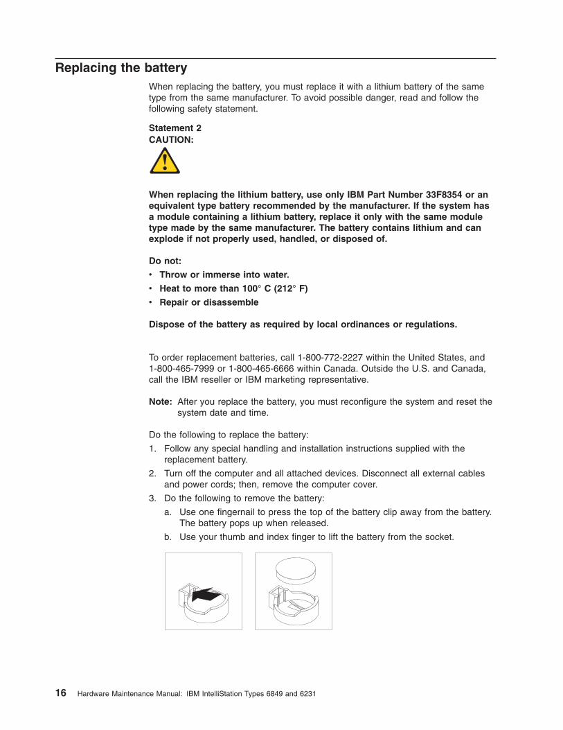
Do the following to replace the battery:
1. Follow any special handling and installation instructions supplied with the
replacement battery.
2. Turn off the computer and all attached devices. Disconnect all external cables
and power cords; then, remove the computer cover.
3. Do the following to remove the battery:
a. Use one fingernail to press the top of the battery clip away from the battery.
The battery pops up when released.
b. Use your thumb and index finger to lift the battery from the socket.
16 Hardware Maintenance Manual: IBM IntelliStation Types 6849 and 6231

4. Do the following to insert the new battery:
a. Tilt the battery so that you can insert it into the socket on the side opposite
the battery clip.
b. Press the battery down into the socket until it clicks into place. Make sure
the battery clip holds the battery securely.
5. Replace the cover and connect the cables.
6. Turn on the system.
7. Start the BIOS Setup Utility program and set configuration parameters.
v Set the system date and time.
v Set passwords if necessary.
v Save the configuration.
Chapter 3. Diagnostics 17

18 Hardware Maintenance Manual: IBM IntelliStation Types 6849 and 6231

Chapter 4. Configuration
The following configuration programs are provided with the computer:
v BIOS Setup Utility program
This program is part of the BIOS code that comes with the computer. This
program enables you to configure parallel port assignments, change the device
startup sequence, set the date and time, and set passwords.
v SCSISelect Utility program (some models)
With the built-in SCSISelect Utility program, you can configure the devices that
are attached to the optional SCSI adapter. See “Using the SCSISelect Utility
program” on page 20 for more information.
Using the BIOS Setup Utility program
This section provides the instructions for starting and using the BIOS Setup Utility
program.
Starting the BIOS Setup Utility program
The prompt, Hit <F2> if you want to run SETUP, might not be displayed when
you start the computer. Do the following to start the BIOS Setup Utility program:
Notes:
1. If the computer is already on when you start this procedure, shut down the
operating system, turn off the computer, and wait a few seconds until all in-use
lights turn off.
2. Turn on the power. Immediately press and hold down the F1 or F2 key until you
see either the BIOS Setup Utility menu or a password prompt.
If you have set neither a supervisor nor a user password, the BIOS Setup Utility
menu opens on the screen. If you have set a password, the BIOS Setup Utility
menu will not open until you type the password and press Enter.
After the BIOS Setup Utility program is started
Once the BIOS Setup Utility is started, help information and instructions for using
the keyboard are displayed on the right side of the screen. You can find more
information about using the BIOS Setup Utility by using Access IBM.
To display the Hit <F2> if you want to run SETUP prompt every time you start
computer, do the following from within the BIOS Setup Utility:
1. Select Boot from the main menu across the top of the screen.
2. Set Quiet Boot to [Disabled].
3. Set Intel« Rapid BIOS Boot to [Disabled].
4. Select Exit from the menu.
5. Select Exit Saving Changes.
The next time you start the computer, Hit <F2> if you want to run SETUP will be
displayed.
© Copyright IBM Corp. 2000, 2001 19

Using the SCSISelect Utility program
SCSISelect is a built-in, menu-driven configuration utility program that you can use
to:
v View the default SCSI IDs
v Locate and correct configuration conflicts
The following sections provide the instructions for starting the SCSISelect Utility
program and descriptions of the menu choices that are available.
Starting the SCSISelect Utility program
Do the following to start the SCSISelect Utility program:
1. Turn on the computer.
2. When the <<< Press <CTRL><A> for SCSISelect¬ Utility! >>> prompt
appears, press Ctrl+A.
3. When the prompt, Would you like to configure the host adapter or run the
SCSI disk utilities?, is displayed, make the selection, and press Enter.
4. Use the arrow keys to make a selection from the menu.
v Press Esc to exit the SCSISelect Utility program.
v Press the F5 key to switch between color and monochrome modes (if the
monitor permits).
5. Follow the instructions on the screen to change the settings of the selected
items; then, press Enter.
Selections available from the SCSISelect menu
The following selections appear on the SCSISelect Utility menu:
v Configure/View Host Adapter Settings
Use this selection to view or change the SCSI controller settings. To reset the
SCSI controller to its default values, press F6; then, follow the on-screen
instructions.
You can view or change the following controller settings:
– Host Adapter SCSI ID
Use this selection to view the SCSI controller identification (ID), which is
usually 7.
– SCSI Parity Checking
Use this selection to view the assigned value of Enabled.
– Host Adapter SCSI Termination
Use this selection to view the assigned value of Automatic.
– Boot Device Options
Use this selection to configure startable-device parameters. To make changes,
you must know the ID of the device you want to configure.
20 Hardware Maintenance Manual: IBM IntelliStation Types 6849 and 6231

– SCSI Device Configuration
Use this selection to configure SCSI-device parameters. To make changes,
you must know the ID of the device you want to configure.
Note: The Maximum Sync Transfer Rate represents the transfer rate for Ultra
SCSI devices.
- The transfer rate for Ultra 160 low voltage differential (LVD) devices
is 160.0 Mbps.
- The transfer rate for Ultra2 SCSI LVD devices is 80.0 Mbps.
- The transfer rate for Fast SCSI devices is 20.0 Mbps.
– Advanced Configuration Options
Use this selection to view or change settings such as enabling support for
large hard disk drives and support for drives with Ultra SCSI speeds.
v SCSI Disk Utilities
Select this choice to view the SCSI IDs that are assigned to each device or to
format a SCSI device.
To use the utility program, select a drive from the list. Read the on-screen
instructions carefully before making a selection.
Note: If you press Ctrl+A before the selected drives are ready, an Unexpected
SCSI Command Failure screen might appear. Restart the computer and
watch the SCSISelect messages as each drive starts. After the drive that
you want to view or format starts, press Ctrl+A.
Chapter 4. Configuration 21

22 Hardware Maintenance Manual: IBM IntelliStation Types 6849 and 6231
Chapter 5. Installing options
Before you begin
Before you begin to install options in the computer, read the following information:
v Become familiar with the safety and handling guidelines specified under
“Handling static sensitive devices” on page 104, and read the safety statements
in “Safety information” on page 101. These guidelines will help you work safely
with the computer or options.
v Make sure that you have an adequate number of properly grounded electrical
outlets for the computer, monitor, and any other options that you intend to install.
v Back up all important data before you make changes to hard disk drives.
v Have a small, flat-blade screwdriver available.
v For a list of supported options for the computer, refer to
http://www.ibm.com/pc/support on the World Wide Web.
System reliability considerations
To help ensure proper cooling and system reliability, make sure:
v Each of the drive bays either has a drive, or a filler panel and electromagnetic
compatibility (EMC) shield installed.
v There is space around the computer to allow the computer cooling system to
work properly. Leave about 127 mm (5 in.) of space around the front and rear of
the computer.
v Cables for optional adapters are routed according to the instructions that are
provided with the adapters.
v A failed fan is replaced within 1 hour.
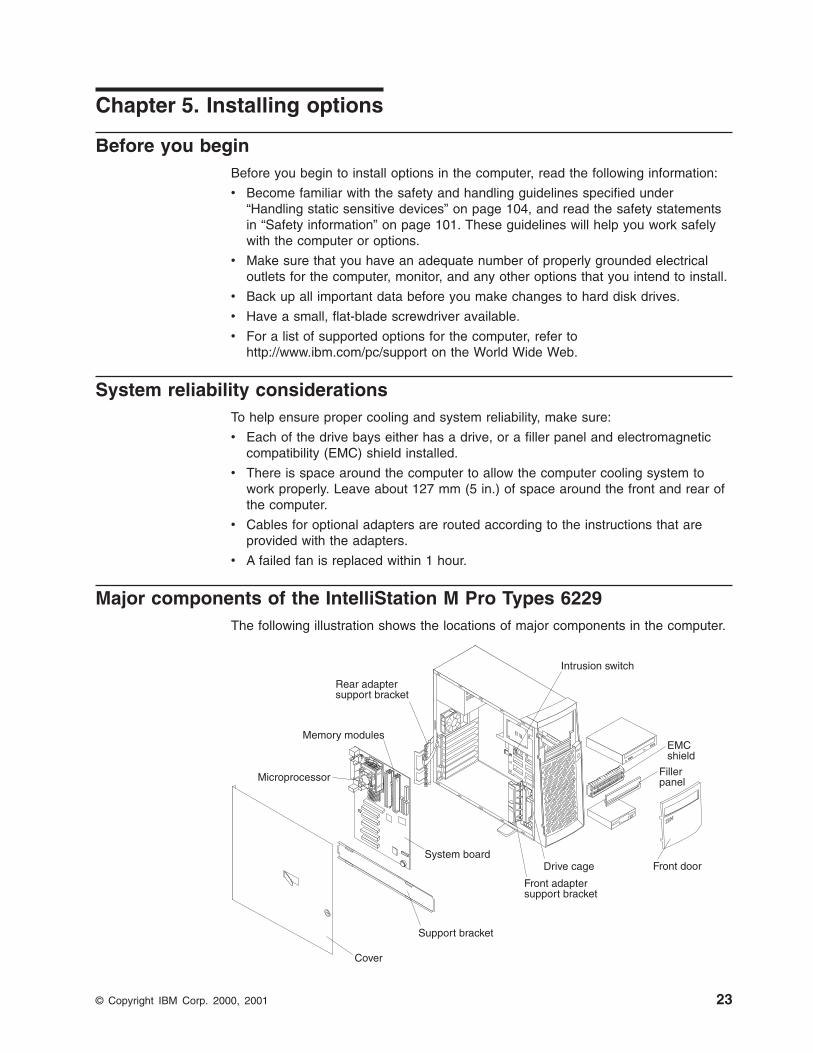
Major components of the IntelliStation M Pro Types 6229
The following illustration shows the locations of major components in the computer.
Rear adaptersupport bracket
Front adaptersupport bracket
Drive cage
Microprocessor
Memory modules
System board
Cover
Support bracket
EMCshield
Fillerpanel
Intrusion switch
Front door
© Copyright IBM Corp. 2000, 2001 23

System board
The illustrations in the following sections highlight various components on the
system board.
This system board illustration identifies parts of the board. Depending on installed
options, your system board might look slightly different.
SCSI LED(J9A1)
PCI 1
PCI 2
PCI 3
PCI 4
PCI 5
Battery
AGP(J5E1)
RIMM 1
Microprocessor(J4K1)
RIMM 2RIMM 3
RIMM 4
24 Hardware Maintenance Manual: IBM IntelliStation Types 6849 and 6231

Internal cable connectors
The following illustration identifies system board connectors for internal cables.
Speaker (J1D2) CD-ROMAudio (J2D1)
Fan 1 I/O bracketfan (J10A2)
Fan 3 Supportbracket assembly
fan (J6L1)Fan 2 Microprocessor
fan sink (J7M2)Fan 4
(J3M1)
Wake on LAN(WOL)
Wake onmodem ring(WOR)
Secondary IDE(SEC IDE)
Primary IDE(PRI IDE)
Diskette drive(Floppy)
Auxiliary power(J9J1)
Main power(J10K1)
Microprocessorpower (J3H1)
Chassisintrusion switch(J10D1)
Front panelpower switchand HDD LED(J9C2)
Chapter 5. Installing options 25

CMOS recovery jumper
The following illustration identifies the CMOS recovery jumper on the system board.
CMOS jumper(J8C2)
The CMOS recovery jumper can be used to clear CMOS memory in the event you
loose your user password. The above illustration shows the location of the CMOS
recovery jumper. See “Erasing a lost or forgotten password (clearing CMOS)” on
page 14 on how to use the CMOS jumper.
This jumper is also used to recover from a BIOS failure. See “Recovering from a
POST/BIOS update failure” on page 15.
26 Hardware Maintenance Manual: IBM IntelliStation Types 6849 and 6231

Moving the stabilizing feet
The two front feet attached to the bottom of the computer rotate outward 90
degrees to provide additional stability when the computer is upright.
To access the inside of the computer, you might find it easier to lay the computer on
its side. Before laying the computer on its side, rotate the feet inward so the weight
of the computer does not break them.
When you are finished and have reinstalled the side cover, turn the two front
stabilizing feet a quarter turn outward and set the computer carefully back on its
feet.
Chapter 5. Installing options 27

Removing the side cover
The following information describes how to remove the side cover.
Note: To remove the cover, you might find it easier to lay the computer on its side.
The illustrations in this document might differ slightly from your hardware.
Do the following to remove the side cover of the computer:
1. Review the information in “Before you begin” on page 23 and “Safety
information” on page 101.
2. Turn off the computer and all attached devices.
3. Disconnect all external cables and power cords.
4. Unlock the computer cover, if necessary.
5. While pressing on the top blue button, pull out the cover-release latch and lock
it into an upright position. This action will slide the cover toward the rear of the
computer about 12.7 mm (0.5 in.). Then, remove the cover from the computer.
Key lock
Cover-releaselatch
To replace the side cover, see “Replacing the cover” on page 41.
Attention
For proper cooling and airflow, replace the cover before turning on the
computer. Operating the computer with the cover removed might damage
computer components.
28 Hardware Maintenance Manual: IBM IntelliStation Types 6849 and 6231

Removing the support bracket
When working with some options, such as hard disk drives, adapters, and memory
modules, you must first remove the support bracket to access the existing option.
Do the following to remove the support bracket:
1. Pull out, about 152.4 mm (6 in.), on the end of the support bracket located at
the rear of the computer.
2. Pull the rear end of the support bracket away from the computer and place the
bracket aside.
To reinstall the support bracket, reverse the previous steps.
Chapter 5. Installing options 29

Working with adapters
The computer comes with adapter connectors or slots. The AGP video adapter is
installed in the AGP slot. You can install up to five PCI adapters in PCI slots 1
through 5. All PCI slots are 32-bit, 33 MHz slots.
Note: Because of its width, the Fire GL4 video adapter requires both the AGP slot
and the adjacent PCI slot. If your model contains a Fire GL4 video adapter,
you can install up to four PCI adapters in PCI slots 2 through 5.
Note: The illustrations in this document might differ slightly from your hardware.
The following illustration shows the location of expansion slots on the system board.
PCI slot 1
PCI slot 2
PCI slot 3
PCI slot 4
PCI slot 5
AGP slot
Adapter considerations
Before you install adapters, review the following:
v Follow the instructions that come with the adapter in addition to the instructions
in this chapter. If you need to change the switch or jumper settings on your
adapter, follow the instructions that come with the adapter.
v You can install full-length adapters in all 5 PCI slots.
v The computer supports 5.0 V and universal PCI adapters; it does not support 3.3
V adapters.
v For a list of supported options for the computer, refer to
http://www.ibm.com/pc/support on the World Wide Web.
30 Hardware Maintenance Manual: IBM IntelliStation Types 6849 and 6231

Installing an adapter
Do the following to install an adapter:
Attention: When you handle static-sensitive devices, take precautions to avoid
damage from static electricity. For details on handling these devices, see “Handling
static sensitive devices” on page 104.
1. Review the information in “Safety information” on page 101.
2. Turn off the computer and attached devices.
3. Disconnect all external cables and power cords; then, remove the side cover.
See “Removing the side cover” on page 28.
4. Determine which PCI slot you will use for the adapter.
Note: Check the instructions that come with the adapter for any requirements,
restrictions, or cabling instructions. It might be easier to route any
cables before you install the adapter.
5. For full-length adapters, rotate the rear adapter support bracket to the open
(unlocked) position and remove it from the computer. Rotate the front adapter
support bracket to the open position. If you are installing a smaller adapter,
remove only the rear support bracket.
6. Remove the expansion-slot cover. From the rear of the computer, press on the
slot cover. Grasp it and pull it out of the expansion slot. Store it in a safe place
for future use.
Attention
Expansion-slot covers must be installed on all vacant slots. This
maintains the electromagnetic emissions standards of the computer and
ensures proper ventilation of computer components.
7. Set any jumpers or switches on the adapter or system board as described by
the adapter manufacturer.
8. When you are ready, remove the adapter from the static-protective package. It
is best to move the adapter directly from the static-protective package to the
adapter slot. If this is not possible, set the adapter down on a non-conductive
surface. Avoid touching the components and gold-edge connectors on the
adapter.
Chapter 5. Installing options 31

9. To install the adapter, carefully grasp the adapter by the top edge or upper
corners, and align it with the expansion slot guides; then, press the adapter
firmly into the expansion slot.
Rearadaptersupportbracket
Expansionslot cover
Frontadaptersupportbracket
Adapter
Attention
Be certain that the adapter is correctly seated in the expansion slot
before you turn on the computer. Incomplete installation of an adapter
might damage the system board or the adapter.
10. Connect required cables to the adapter. Route cables so that they do not block
the flow of air from the fans.
11. If you have another adapter to install, repeat steps 1 - 10. If you have another
option to install, do so at this time. Otherwise, complete the rest of the steps in
this section.
12. If you have installed a full-length adapter, rotate the front adapter support
bracket to the closed (locked) position.
13. Reinstall the rear adapter support bracket; then, rotate the bracket to the
closed (locked) position.
Note: The rear retaining bracket sits against the computer cover. You might
find it easier to lay the computer on its side to replace the cover.
14. Replace the support bracket.
15. Replace the side cover, see “Replacing the cover” on page 41 for details.
16. Reconnect the external cables and power cords; then, turn on the attached
devices and the computer.
32 Hardware Maintenance Manual: IBM IntelliStation Types 6849 and 6231

Installing an optional SCSI adapter
Some models come without SCSI adapters. Do the following to install an optional
SCSI adapter:
1. If you do not have a preinstalled SCSI adapter, complete steps 1 through 10 of
“Installing an adapter” on page 31. Continue with step 2 of this procedure.
2. Connect the SCSI signal cable to the adapter; then, connect one or more of the
signal cable connectors to the rear of the SCSI devices.
3. Connect the SCSI activity indicator cable to the adapter and to the SCSI LED
connector (JA91) on the system board. See “System board” on page 24 for the
location of the SCSI LED connector.
Rearadaptersupportbracket
Frontadaptersupportbracket
SCSIAdapter SCSI
activityindicatorcable
SCSILED(JA91)
SCSI signalcable connector
SCSI activityindicator cableconnector
SCSIsignalcable
4. If you have other adapters or options to install or remove, do so now.
5. Rotate the front adapter support bracket to the closed (locked) position.
6. Reinstall the rear adapter support bracket; then, rotate it to the closed (locked)
position.
7. Replace the support bracket.
8. Replace the cover. See “Replacing the cover” on page 41 for details.
9. Reconnect the external cables and power cords; then, turn on the attached
devices and the computer.
Chapter 5. Installing options 33

Installing internal drives
Depending on the computer model, you might have one or more of the following
drives installed.
v Diskette
v Hard disk
v CD- or DVD-ROM
v Jaz or Zip
v Tape
Internal drive bays
The IntelliStation M Pro computer comes with an IDE CD-ROM or DVD-ROM drive
in bay 1, a 3.5-in., 1.44 MB diskette drive in bay 3, and a hard disk drive installed in
bay 5.
Bay 1
Bay 2
Bay 3
Bay 4
Bay 5
Bay 6
Bay 7
Notes:
1. Diskette drives, tape drives, and CD-ROM and DVD-ROM drives are examples
of removable media drives. You can install removable-media drives in bays 1, 2,
3, and 4 only.
2. You can install a 3.5-in, slim-high, or a 5.25-in., half-high, removable-media
drive, such as a tape backup drive, in bay 2.
3. You can only install a 3.5-in., slim-high, removable-media drive in bay 4.
4. The IntelliStation M Pro computer supports only one diskette drive, which uses
1.44 MB diskettes.
5. To install a 3.5-in. drive in a 5.25-in. bay, you must use a 5.25-in. conversion kit,
supplied with the option.
34 Hardware Maintenance Manual: IBM IntelliStation Types 6849 and 6231

6. The electromagnetic interference (EMI) integrity and cooling of the computer are
protected by having all bays and PCI slots covered or occupied. When you
install a drive or PCI adapter, save the EMC shield and filler panel from the bay
or the PCI adapter slot cover in the event you later remove the option.
7. For a complete list of supported options for the computer, refer to
http://www.ibm.com/pc/support on the World Wide Web.
Preinstallation steps (all bays)
Before you install a drive in the computer, verify that you have all the cables and
other equipment specified in the documentation that comes with the drive. You
might also need to perform certain preinstallation activities. Some of the steps are
required only during the initial installation of an option.
1. Read “Safety information” on page 101, “Handling static sensitive devices” on
page 104 and the documentation that comes with the drive.
2. Choose the bay in which you want to install the drive.
3. Check the instructions that come with the drive to see if you need to set any
switches or jumpers on the drive. If you are installing a SCSI device, be sure to
set the SCSI ID for that device.
Installing a drive in bay 2 or 4
Do the following to install a drive in bay 2 or 4:
Attention
When handling static-sensitive devices, take precautions to avoid damage
from static electricity.
1. Read the information in “Preinstallation steps (all bays)” on page 35.
2. Turn off the computer and attached devices and disconnect the external cables
and power cords.
3. Remove the side cover. See “Removing the side cover” on page 28 for details.
4. Remove the support bracket (see “Removing the support bracket” on page 29).
Chapter 5. Installing options 35

EMC shield
Filler panel
5. Use a screwdriver to pry the filler panel and EMC shield away from the
computer.
Note: If you are installing a drive that contains a laser, observe the following
safety precaution.
Statement 3
CAUTION:
When laser products (such as CD-ROMs, DVD drives, fiber optic devices, or
transmitters) are installed, note the following:
v Do not remove the covers. Removing the covers of the laser product could
result in exposure to hazardous laser radiation. There are no serviceable
parts inside the device.
v Use of controls or adjustments or performance of procedures other than
those specified herein might result in hazardous radiation exposure.
Danger
Some laser products contain an embedded Class 3A or Class 3B laser diode. Note
the following. Laser radiation when open. Do not stare into the beam, do not view
directly with optical instruments, and avoid direct exposure to the beam.
36 Hardware Maintenance Manual: IBM IntelliStation Types 6849 and 6231

6. Touch the static-protective package containing the drive to any unpainted metal
surface on the computer; then, remove the drive from the bag and place it on
a static-protective surface.
7. Set any jumpers or switches on the drive according to the documentation that
comes with the drive.
8. You might find it easier to install the new drive into the appropriate opening on
the machine front, then attach the cables.
9. If you are installing a 5.25-in. drive in bay 2, push the drive into the bay; then,
use the two screws to attach the drive to the drive cage.
10. If you are installing a 3.5-in. drive in bay 2, you must attach the 5.25-in
conversion kit, supplied with the option, to the 3.5-in. drive.
Note: You can install only a 3.5-in. device in bay 4.
11. If the drive is an IDE device, connect one end of the IDE signal cable into the
back of the drive and the other end of the cable into the IDE connector on the
system board. For the location of the IDE connectors, see “Internal cable
connectors” on page 25. If the drive is a SCSI device, connect one end of the
SCSI signal cable into the back of the drive and the other end of the cable into
the SCSI adapter.
Note: Make sure to route the SCSI signal cable so that it does not block the
air flow to the rear of the drives or over the microprocessor.
12. Connect a power cable to the back of the drive. The connectors are keyed and
can be inserted only one way.
13. If you have other options to install or remove, do so now.
14. Replace the support bracket.
15. Replace the side cover. See “Replacing the cover” on page 41 for details.
16. Reconnect the external cables and power cords; then, turn on the attached
devices and the computer.
Installing a hard disk drive in bay 5, 6, or 7
You might find it useful to work with the computer laying on its side. Bays 5, 6, and
7 are in the drive cage. The drive cage is located just above the front adapter
support bracket. Refer to the following illustration as you work with the drive cage.
1. Read the information in “Preinstallation steps (all bays)” on page 35.
2. Turn off the computer and all attached devices. Disconnect all external cables
and power cords; then, remove the cover. See “Removing the side cover” on
page 28 for details.
Chapter 5. Installing options 37

3. Remove the support bracket.
4. Access the drive cage.
a. If the computer has hard disk drives preinstalled in the drive cage,
disconnect the power and signal cables from the rear of the drives.
b. Grasp the drive cage and rotate the cage out (middle view above) of the
computer until it locks into place with the drive cage retention tab. The
open ends of the drive slots and installed drives will face you.
Note: Ensure that the drive cage locks into place over the drive cage
retention tab by pressing the drive cage all the way up.
5. Attach the guide rails to the side of the drive using the screws provided. If you
obtained the optional drive from IBM, the guide rails are blue plastic.
6. Slide the drive into the drive cage until the plastic tabs on the drive guide rails
lock into place in the drive cage.
7. Lift the drive cage up, and press in on the drive cage release tab; then, rotate
the cage back into the computer (right view above).
Note: Clear any cables that might impede the replacement of the drive cage.
8. Connect the power and signal cables to the rear of each drive and to the
system board if necessary.
Note: Route the signal cable so that it does not block the air flow to the rear
of the drives or over the microprocessor.
9. If you have other options to install or remove, do so now.
10. Replace the support bracket.
11. Replace the side cover, see “Replacing the cover” on page 41 for details.
12. Reconnect the external cables and power cords; then, turn on the attached
devices and the computer.
Installing memory modules
Adding memory to the computer is an easy way to make programs run faster. You
can increase the amount of memory in the computer by installing memory modules.
The IntelliStation M Pro computer uses industry-standard, RAMBUS in-line memory
modules (RIMMs).
Notes:
1. Any connector that does not have a RIMM installed must have a continuity
RIMM (C-RIMM), a module that looks like a RIMM but has no memory on it. A
C-RIMM is used to continue the connection on a RIMM connector that does not
have memory installed.
2. Install only ECC RIMMs to enable ECC. If you use ECC and non-ECC memory
together, it will function as non-ECC memory.
3. RIMM connectors do not support dual inline memory modules (DIMMs).
4. Use only PC600 or PC800 RIMMs.
Note: If you use PC600 and PC800 RIMMs together, all memory will function at
the speed of the slowest RIMM.
5. The IntelliStation M Pro computer supports 128 MB, 256 MB, and 512 MB
RIMMs. The computer supports a minimum of 128 MB and a maximum of 2.0
GB of system memory. Go to http://www.ibm.com/pc/support for a list of memory
modules to use with the computer.
38 Hardware Maintenance Manual: IBM IntelliStation Types 6849 and 6231

6. RIMMs must be installed in matched pairs (same type and capacity). RIMM 1
and 2 are a pair; RIMM 3 and 4 are a pair.
Note: The illustrations in this document might differ slightly from your hardware.
RIMM connector 1
RIMM connector 2
RIMM connector 3
RIMM connector 4
Retaining clip
Do the following to install a RIMM or C-RIMM:
Attention: When handling static-sensitive devices, take precautions to avoid
damage from static electricity. For details on handling these devices, see “Handling
static sensitive devices” on page 104.
1. Review the safety precautions listed in the “Safety information” on page 101.
2. Turn off the computer and all attached devices. Disconnect all external cables
and power cords; then, remove the cover. See “Removing the side cover” on
page 28 for details.
3. Remove the support bracket.
4. Touch the static-protective package containing the RIMM to any unpainted
metal surface on the computer. Then, remove the new RIMM from the
package.
5. Open the retaining clips and, if necessary, remove any existing RIMM or
C-RIMM.
6. Gently open the retaining clip on each end of the RIMM slot. Turn the RIMM
so that the pins align correctly with the connector.
Chapter 5. Installing options 39

7. Insert the RIMM into the connector by aligning the RIMM edges with the slots
at each end of the RIMM connector. Firmly press the RIMM straight down into
the connector by applying pressure on both ends of the RIMM simultaneously.
The retaining clips snap into the locked position when the RIMM is firmly
seated in the connector.
8. If a gap exists between the RIMM and the retaining clips, the RIMM has not
been correctly installed. Open the retaining clips, remove the RIMM, then
reinsert it.
9. If you have other options to install or remove, do so now. Otherwise, finish the
installation with the steps below.
10. Replace the support bracket.
11. Replace the side cover. See “Replacing the cover” on page 41.
12. Reconnect the external cables and power cords. Turn on the attached devices,
then the computer.
Installing a security U-bolt
To help prevent theft, you can add a security U-bolt and cable to the computer. This
section discusses how to install a security U-bolt.
Do the following to install the U-bolt:
1. Review the safety precautions listed in “Safety information” on page 101.
2. Turn off the computer and all attached devices. Disconnect all external cables
and power cords; then, remove the cover. See “Removing the side cover” on
page 28 for details.
3. Use a screwdriver to remove the two metal knockouts.
4. Insert the U-bolt through the rear panel; then, attach and tighten the nuts.
40 Hardware Maintenance Manual: IBM IntelliStation Types 6849 and 6231

Note: Your computer might look different slightly different than the one shown.
5. Thread the cable through the U-bolt and around an object that is not part of or
permanently secured to the building structure or foundation, and from which the
cable cannot be removed. Fasten the cable ends together with a lock. After you
add the security cable, be certain it does not interfere with other cables
connected to the computer.
6. Reconnect the external cables and power cords, and turn on the attached
devices and the computer.
Replacing the cover
The following information describes replacing the cover.
Notes:
1. Because of the placement of the adapter support brackets, you might find it
easier to lay the computer on it side with the cover lock facing you.
2. If you removed the support bracket, reinstall it before you replace the cover.
See “Removing the support bracket” on page 29 for details.
Do the following to replace the computer cover:
1. Clear any cables that might impede the replacement of the cover.
2. Install the side cover by placing it into position on the computer. Be certain the
notches on the underside of the cover match up to the holes along the sides of
the computer. Press down on the cover release latch button as you close the
cover release latch to lock the cover.
Chapter 5. Installing options 41

3. If you have not done so already, make sure that the two front stabilizing feet are
rotated outward so that they properly support the computer. Rotate each
individual foot outward 90 degrees.
4. Reconnect the external cables and power cords to the computer; then, connect
the power cords to electrical outlets.
5. Turn on the attached devices; then, turn on the computer.
Connecting external devices
You can attach several external devices to the computer. To attach an external
device:
1. Be sure the computer and all attached devices are turned off.
2. Read “Before you begin” on page 23 and the documentation that comes with
the options.
3. Follow the instructions that come with the option to prepare it for installation and
to connect it to the computer.
42 Hardware Maintenance Manual: IBM IntelliStation Types 6849 and 6231

Input/Output connector descriptions
This section provides pin and other information about the I/O connectors on the rear
of the computer. Refer to “Input/Output connector locations.” These connectors
include the following:
v One mouse
v One keyboard
v One parallel
v Two serial
v One Ethernet
v Two USB
v Line in
v Line out
v Microphone
v One video (Optional multiple connectors on some models)
v One Ultra 3/160 SCSI (some models)
Input/Output connector locations
The following illustration shows the input/output connectors and the expansion slots
on the rear of the computer. For pin assignments and more details about these
connectors, see the individual descriptions that follow.
Power cordconnectorMouse
Keyboard
ParallelSerial 1Serial 2
USB 2USB 1
Mic (pink)
Line in (blue)Line out (green)
Ethernet
Video
SCSI (optional)
11
22
Mouse connector
The computer has one mouse connector that supports a mouse or other pointing
device. The mouse connector is located on the rear of the computer. See
“Input/Output connector locations.”
6
4
2 1
3
5
Chapter 5. Installing options 43

Keyboard connector
The computer has one keyboard connector. See “Input/Output connector locations”
on page 43 for its location.
Note: If you attach a standard (non-USB) keyboard to the keyboard connector, the
USB ports and devices are disabled during the power-on self-test (POST).
6
4
2 1
3
5
Parallel connector
The computer has one parallel connector. This connector supports three standard
Institute of Electrical and Electronics Engineers (IEEE) 1284 modes of operation:
standard parallel port (SPP), enhanced parallel port (EPP), and extended capability
port (ECP).
Viewing or changing the connector assignments
Use the BIOS Setup Utility program to configure the parallel connector as
bi-directional. With this configuration, data can be read from and written to a device.
In bidirectional mode, the computer supports the ECP and EPP modes.
Do the following to view or change the parallel-connector assignment:
1. Restart the computer.
2. Press and hold the F2 key to launch the BIOS Setup Utility.
3. On the BIOS Setup Utility menu, use the cursor keys on the keyboard to select
Advanced”Peripheral Configuration”Parallel Port.
Note: When you configure the parallel connector as bi-directional, use an IEEE
1284-compliant cable. The cable must not exceed 3 meters (9.8 ft.).
4. Follow the instructions on the screen to save the changes and exit from the
BIOS Setup Utility menu.
Parallel connector
There is a 25-pin, female D-shell parallel connector on the rear of the computer.
See “Input/Output connector locations” on page 43 for the location of this connector.
13 1
25 14
Serial connectors
The computer has two standard 9-pin D-shell serial connectors: Serial connector 1
and Serial connector 2. See “Input/Output connector locations” on page 43 for their
location.
1 5
6 9
44 Hardware Maintenance Manual: IBM IntelliStation Types 6849 and 6231

Ethernet connector
The computer comes with an integrated Ethernet controller. This controller provides
an interface for connecting to 10-Mbps or 100-Mbps networks and provides
full-duplex capability, which enables simultaneous transmission and reception of
data on an Ethernet LAN.
To access the Ethernet connector, attach a Category 3, 4, or 5 unshielded
twisted-pair (UTP) cable to the RJ-45 connector on the rear of the computer. See
“Input/Output connector locations” on page 43.
Important
To operate the computer within FCC Class A or Class B limits, use a category
5 Ethernet cable.
Universal Serial Bus connectors
The computer has two Universal Serial Bus (USB) connectors, which configure
automatically when you use any USB device. USB is a serial interface standard for
telephony and multimedia devices. It uses Plug and Play technology to determine
the type of device attached to the connector.
Notes:
1. If you attach a standard (non-USB) keyboard to the keyboard connector, the
USB connectors and devices will be disabled during the power-on self-test.
2. If you install a USB keyboard that has a mouse connector, the USB keyboard
emulates a mouse, and you will not be able to disable the mouse settings in the
BIOS Setup Utility program.
USB cables
Use a 4-pin USB cable to connect external devices to USB connectors.
USB technology transfers data at up to 12 megabits-per-second (Mbps) with a
maximum of 127 external devices and a maximum signal distance of five meters
(16 ft) per segment.
USB connectors
See “Input/Output connector locations” on page 43 for the location of the USB
connectors.
1 4
Chapter 5. Installing options 45

Audio connectors
The audio connectors are used to connect external audio equipment to the
computer. See “Input/Output connector locations” on page 43 for the location of
these connectors.
Line out (green)
Line in (blue)
Mic (pink)
Line out
This connector is used to send audio signals from the computer to external devices,
such as powered speakers with built-in amplifiers, headphones, multimedia
keyboards, or the audio Line in connector on a stereo system.
Note: The internal speaker in your computer is disabled when any device is
attached to this connector.
Line in
This connector is used to accept audio signals from external devices, such as line
output from a stereo, television, or musical instrument into the computer sound
system.
Microphone
This connector is used to connect a microphone to your computer when you want
to record voice or other sounds on the hard-disk drive. It can also be used by
speech recognition software.
Video connector
The computer uses an AGP adapter located in the AGP slot on the system board.
The video connector is on the adapter and is located on the rear of the computer.
See “Input/Output connector locations” on page 43 for the location of this connector.
Analog video connector:
15
1115
Digital (DVI-I) video connector:
1 C1 C2
C3C5
C4
Models with the Fire GL4 video adapter come with a digital-to-analog converter for
each DVI-I connector.
Some models come with an AGP adapter that has dual video connectors.
Attention: On the Fire GL4 video adapter, the first or only monitor must be
connected to the bottom connector (connector number 1).
46 Hardware Maintenance Manual: IBM IntelliStation Types 6849 and 6231

Ultra 3/160 SCSI connector
Some computer models come with a SCSI adapter, which supports an Ultra
3/160/MB SCSI internal channel in a full-featured PCI 2.1-/2.2-compliant bus master
package. This configuration supports zero wait state, 32-bit memory transfers at
160 Mbytes/second, when low voltage differential (LVD) SCSI peripherals are
attached. This channel supports up to 15 SCSI devices. In addition, this adapter
uses:
v Double-transition clocking to achieve high transfer rates
v Domain name validation to negotiate compatible data transfer speeds with each
device
v Cyclic-redundancy checking, instead of the usual parity checking, to significantly
improve data reliability
SCSI cabling requirements
You can install five internal SCSI devices using the SCSI signal cable that comes
with your computer. If you plan to attach external SCSI devices, you must order an
additional SCSI cable. To select and order the correct cables for use with external
devices, contact your IBM reseller or IBM marketing representative. To receive an
indication of SCSI hard-disk drive activity, you must also connect the SCSI adapter
to the SCSI LED (JA91) connector on the system board. See “System board” on
page 24 for the location of the SCSI connector.
Setting SCSI IDs
Each SCSI device connected to a SCSI controller must have a unique SCSI ID.
This ID enables the SCSI controller to identify the device and ensure that different
devices on the same SCSI channel do not attempt to transfer data simultaneously.
SCSI devices that are connected to different SCSI channels can have duplicate
SCSI IDs. Refer to the information that is provided with the device for instructions to
set its SCSI ID. With a SCSI adapter installed in your computer, you can use its
68-pin SCSI connector to connect different types of SCSI devices.
34 1
68 35
To install external SCSI devices, you must have an optional SCSI PCI adapter
installed. Refer to the information that is provided with the device for instructions to
set its SCSI ID.
Chapter 5. Installing options 47

48 Hardware Maintenance Manual: IBM IntelliStation Types 6849 and 6231

Chapter 6. FRU information (service only)
This section covers the service removals for Type 6849 and 6231 computers.
Note: This section is for trained servicers
Type 6849 and 6231 removals
System board layout
SpeakerCDAudio
Fan 1
Fan 3
Fan 2
Fan 4
Alerton LAN
Wakeon LAN
SC
SIL
ED
PCI PCI PCI PCI PCI
BackupBattery
RecoveryJumper
CPU
AGPConnector
Your computermay not have all
connectors shown.
Secondary IDE
RIMM 1
FDD Connector
Primary IDE
RIMM 2
RIMM 3
RIMM 4
Power
Power
Power
FrontPanel
USBTamper Alert
System board jumper settings
The following table contains the jumper setting information. (D) indicates the default
setting.
Configuration/Flash Boot Block Recovery: Use the recovery jumper setting to
configure CMOS or to Flash Boot Block Recover.
Jumper Setting Description
CMOS Reset Remove Flash recovery
1-2 (D) Normal Mode
© Copyright IBM Corp. 2000, 2001 49
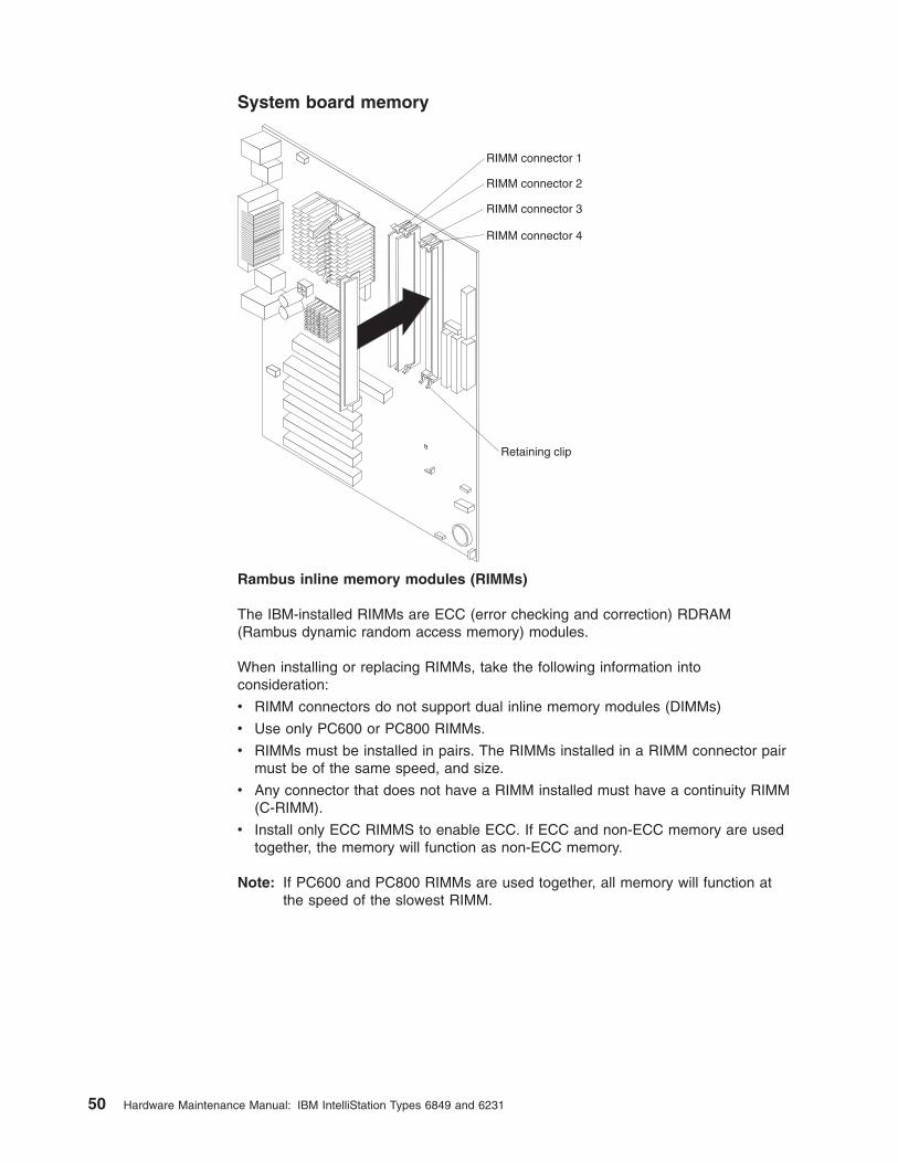
System board memory
RIMM connector 1
RIMM connector 2
RIMM connector 3
RIMM connector 4
Retaining clip
Rambus inline memory modules (RIMMs)
The IBM-installed RIMMs are ECC (error checking and correction) RDRAM
(Rambus dynamic random access memory) modules.
When installing or replacing RIMMs, take the following information into
consideration:
v RIMM connectors do not support dual inline memory modules (DIMMs)
v Use only PC600 or PC800 RIMMs.
v RIMMs must be installed in pairs. The RIMMs installed in a RIMM connector pair
must be of the same speed, and size.
v Any connector that does not have a RIMM installed must have a continuity RIMM
(C-RIMM).
v Install only ECC RIMMS to enable ECC. If ECC and non-ECC memory are used
together, the memory will function as non-ECC memory.
Note: If PC600 and PC800 RIMMs are used together, all memory will function at
the speed of the slowest RIMM.
50 Hardware Maintenance Manual: IBM IntelliStation Types 6849 and 6231

Memory placement for 4-RIMM Memory Card
Number of RIMMs
Pair 1 Pair 2
1 2 3 4
2 RIMMs RIMM RIMM C-RIMM C-RIMM
4 RIMMs RIMM RIMM RIMM RIMM
Note: Memory must be installed in matched pairs.
The following matrix cross-references the name of the computer (printed on the
logo) and the size, speed, and type of memory modules supported in the computer.
Note: RAMBUS inline memory module (RIMM) is used in the type 6849 and 6231
computers. RIMM modules are not compatible with SIMM or DIMM memory
modules. Refer to the information below regarding RIMM memory for type
6849 and 6231.
Computer Name
RIMM Memory Module
Size Memory Type
IntelliStation Type 6849 and 6231 64 MB 128MB PC600 RDRAM
256 MB 512 MB; PC800 ECC/Non-ECC
2 GB Maximum
Supported RIMM memory configuration
Type 6849 and 6231 has two memory channels with two memory sockets for each
channel making a total of four RIMM memory sockets. RIMM sockets must have a
RIMM memory module or a C-RIMM (RIMM Continuity module) installed. There can
be no empty RIMM sockets. RIMM sockets must contain either a RIMM or a
CRIMM. At least one socket, from each memory channel, must have a RIMM
memory module installed.
Note: Both memory channels must be populated the same.
v RIMM sockets 1 and 3 are on memory channel A.
v RIMM sockets 2 and 4 are on memory channel B.
Each RIMM socket supports a maximum of 512 MB of memory.
v If new memory is to be added in a memory channel, remove a C-RIMM and
install the new RIMM. (You must also do the same with the other memory
Channel).
v If memory is to be removed from a memory channel, remove the RIMM and
install a C-RIMM. (You must also do the same with the other memory Channel).
RIMM sizes of 64 MB, 128 MB, 256 MB, and 512 MB are acceptable. RIMM
sockets, within each memory channel, can be filled in any order. However, both
memory channels must be populated the same. ECC or non-ECC, RAMBUS
dynamic random access memory (RDRAM) are supported. If ECC and non-ECC
are installed together, all memory will function as non-ECC.
Note: Mixed RIMM speeds will run at the lower speed.
Chapter 6. FRU information (service only) 51

Procedures to determine memory errors:
1. If a memory error occurs, and the system is operational, run memory
diagnostics.
2. If a memory error occurs, and the system is not operational:
a. Replace one RIMM module at a time until the system comes up.
Note: All unused RIMM sockets must have a C-RIMM installed.
b. Run memory diagnostics.
c. Install the other RIMM and run diagnostics again to identify the failing RIMM.
RIMM diagnostic approach
Identify any Beep or POST codes. See Chapter 7, “Symptom-to-FRU index,” on
page 61.
Use the IBM PC Enhanced Diagnostics program to run memory tests. See “IBM
Enhanced Diagnostics” on page 6.
Procedures to determine memory errors
1. If a memory error occurs, and the system is operational, run memory
diagnostics.
2. If a memory error occurs, and the system is not operational:
a. Replace one RIMM module at a time until the system comes up.
Note: All unused RIMM sockets must have a C-RIMM installed. Both memory channels
must be populated the same.
b. Run memory diagnostics.
c. Replace the other RIMMs and run diagnostics again to identify the failing
RIMM.
Replacing a system board
Notes:
1. The BIOS and Vital Product Data (VPD) for the computer you are servicing must be
installed on the new system board (FRU) after it is installed in the computer. To do this,
you must run the Flash Update program using the Flash Update diskette. See
“BIOS levels” on page 89, “Vital product data” on page 87, and “Flash (BIOS/VPD)
update procedure” on page 89.
2. Always ensure the latest level of BIOS is installed on the computer. A down level BIOS
may cause false errors and unnecessary replacement of the system board.
3. The processor is a separate FRU from the system board and is not included with the
system board FRU.
4. If the new system board does not correct the problem, reinstall the options on the old
system board, reinstall the old system board, then replace the processor.
52 Hardware Maintenance Manual: IBM IntelliStation Types 6849 and 6231

To replace the system board, do the following:
1. Remove any components and dsisconnect any cables that impede access to
the system board and processor/heatsink (see the section for each component
for more information).
2. Remove the heatsink, processor and mounting brackets from the old system
board and install them on the new system board (see “Replacing a processor”
on page 54).
3. Remove the 10 screws that attach the system board to the chassis.
4. Remove the board from the chassis.
5. Remove any of the following installed options on the old system board, and
install them on the new system board.
v Memory modules
6. Ensure that the new system board jumper settings match the old system board
jumper settings.
Chapter 6. FRU information (service only) 53

Replacing a processor
To replace the processor, do the following:
1. Remove any components and dsisconnect any cables that impede access to
the fansink/heatsink and processor (see the section for each component for
more information).
2. Remove the fansink/heatsink from the processor.
a. Unplug the fansink cable.
Retention tabs
b. Remove one retention clip by using a small flat-blade screwdriver to
carefully pry one end of the clip off of the retention tab; then, slide the clip
off of the remaining two tabs and lift it out of the machine.
c. Use the same procedure to remove the second retention clip.
d. Lift the fansink up and out of the machine.
54 Hardware Maintenance Manual: IBM IntelliStation Types 6849 and 6231

3. Rotate the processor socket release lever upward to the maximum vertical
position.
Release lever
Orientation marks
Important: Note the location of the orientation marks (triangles) on the processor and
socket to ensure proper orientation of the processor during installation.
4. Lift the processor up and out of the machine.
5. To install the processor and fansink, reverse the previous steps.
Note: During installation, make sure that the processor is fully seated in its socket and that
the goal post latches are engaged.
Impotant:
1. Make sure the fansink and air baffle (if any) are installed to prevent processor
overheating.
2. If the processor is not installed correctly, the system board and the processor can be
damaged.
Chapter 6. FRU information (service only) 55

Speaker removal
1. Remove the cover (see “Removing the side cover” on page 28).
2. The speaker is secured by one tab on either side and two at the bottom. Firmly
push the speaker up from the bottom until it comes out from the tabs.
Power supply
If the power-on indicator is not on, the power supply fan is not running, or the
computer will not power-off, use the following procedures.
Check/Verify FRU/Action
Check the following for proper installation.
v Power Cord
v On/Off Switch connector
v On/Off Switch Power Supply connector
v System Board Power Supply connectors
v Microprocessor(s) connection
Reseat
Check the power-on switch for continuity. Power Cord
Check the power-on switch for continuity. Power-on Switch
56 Hardware Maintenance Manual: IBM IntelliStation Types 6849 and 6231

20-pin main power supply connection
See “System board layout” on page 49 for connector locations.
Attention: These voltages must be checked with the power supply cables connected to
the system board.
1 10
11 20
Pin Signal Function
1 3.3 V +3.3 V dc
2 3.3 V +3.3 V dc
3 COM Ground
4 5 V +5 V dc
5 COM Ground
6 5 V +5 V dc
7 COM Ground
8 POK Power Good
9 5VSB Standby Voltage
10 12 V +12 V dc
11 3.3 V +3.3 V dc
12 -12 V -12 V dc
13 COM Ground
14 PS-ON DC Remote Enable
15 COM Ground
16 COM Ground
17 COM Ground
18 No Voltage Not Used
19 5 V +5 Vdc
20 5 V +5 Vdc
If the voltages are not correct, and the power cord is good, replace the power
supply.
Chapter 6. FRU information (service only) 57

6-pin power supply connection
1 6
Pin Signal Function
1 COM Ground
2 COM Ground
3 COM Ground
4 3.3 V +3.3 V DC
5 3.3 V +3.3 V DC
6 5 V +5 V DC
4-pin power supply connection
21
3 4
Pin Signal Function
1 COM Ground
2 COM Ground
3 12 V +12 V DC
4 12 V +12 V DC
58 Hardware Maintenance Manual: IBM IntelliStation Types 6849 and 6231

Power supply removal
1. Remove the power cable.
2. Remove the cover (see “Removing the side cover” on page 28).
3. Remove the four screws that secure the power supply to the back of the
chassis.
4. Remove the power supply.
Chapter 6. FRU information (service only) 59

60 Hardware Maintenance Manual: IBM IntelliStation Types 6849 and 6231

Chapter 7. Symptom-to-FRU index
The Symptom-to-FRU index lists error symptoms and possible causes. The most
likely cause is listed first. Always begin with Chapter 1, “General checkout,” on page
1. This index can also be used to help you decide which FRUs to have available
when servicing a computer. If you are unable to correct the problem using this
index, go to “Undetermined problems” on page 86.
Notes:
v If you have both an error message and an incorrect audio response, diagnose the error
message first.
v If you cannot run the diagnostic tests or you get a diagnostic error code when running a
test, but did receive a POST error message, diagnose the POST error message first.
v If you did not receive any error message, look for a description of the error symptoms in
the first part of this index.
v Check all power supply voltages before you replace the system board (see “Power
supply” on page 56
Important:
Some errors are indicated with a series of beep codes (see “Beep symptoms” on page 62).
Type 6849 and 6231 computers default to come up quiet (no beep and no memory count
and checkpoint code display) when no errors are detected by POST. To enable beep and
memory count and checkpoint code display when a successful POST occurs, do the
following:
1. Select Start Options in the BIOS Setup Utility program (see “Using the BIOS Setup
Utility program” on page 19).
2. Set Power-On Self-Test to Enhanced.
The processor is a separate FRU from the system board; the processor is not included with
the system board FRU.
In the following indexes, X can represent any number.
RIMM memory errors
The following RIMM error messages are issued by the diagnostic programs.
Error FRU/Action
Corrupt BIOS
Information in BIOS is not as expected.
Not able to find expected DMI information
from BIOS.
Memory controller chipset vendor ID does
not match expected value.
Reflash the BIOS.
Perform boot block recovery.
Replace the system board.
Test aborted by user Restart test.
© Copyright IBM Corp. 2000, 2001 61

Hard disk drive boot error
A hard disk drive boot error can have the following causes.
Error FRU/Action
The start-up drive is not in the boot
sequence in configuration.
Check the configuration and ensure the
start-up drive is in the boot sequence.
No operating system installed on the boot
drive.
Install an operating system on the boot drive.
The boot sector on the start-up drive is
corrupted.
The drive must be formatted, do the
following:
1. Attempt to access and recover (back-up)
the failing hard disk drive.
2. Using the operating systems programs,
format the hard disk drive.
3. Install operating system, and restore files.
The drive is defective. Replace the hard disk drive.
Beep symptoms
Beep symptoms are short tones or a series of short tones separated by pauses
(intervals without sound).
Note: One beep after successfully completing POST indicates the system is
functioning properly.
Use the following table to diagnose beep symptoms.
Beeps FRU/Action
1 Refresh failure. 1. Verify all RIMM slots are occupied correctly. See
“Installing memory modules” on page 38
2. Reseat memory.
3. Test with known good memory. Replace memory if bad.
4. Replace system board.
2 Parity cannot be reset 1. Verify all RIMM slots are occupied correctly. See
“Installing memory modules” on page 38
2. Reseat memory.
3. Test with known good memory. Replace memory if bad.
4. Replace system board.
3 First 64 KB memory
failure.
1. Verify all RIMM slots are occupied correctly. See
“Installing memory modules” on page 38
2. Reseat memory.
3. Test with known good memory. Replace memory if bad.
4. Replace system board.
4 Timer not operational. Change system board.
5 Not used. Not used.
6 8042 GateA20 cannot
be toggled.
Change system board.
62 Hardware Maintenance Manual: IBM IntelliStation Types 6849 and 6231

Beeps FRU/Action
7 Exception interrupt
error.
Change system board.
8 Display memory R/W
error.
1. Verify all RIMM slots are occupied correctly. See
“Installing memory modules” on page 38
2. Reseat memory.
3. Test with known good memory. Replace memory if bad.
4. Replace system board.
9 Not used. Not used.
10 CMOS shutdown
register test error.
Change system board.
11 Invalid BIOS (e.g.
POST module not
found, etc.).
Reflash BIOS.
Chapter 7. Symptom-to-FRU index 63

Diagnostic error codes
Refer to the following diagnostic error codes when using the diagnostic tests. See
Chapter 3, “Diagnostics,” on page 5 for the specific type for information about the
diagnostic programs.
In the following index, X can represent any number.
Diagnostic Error Code FRU/Action
000-000-XXX
BIOS Test Passed
1. No action
000-002-XXX
BIOS Timeout
1. Flash the system
2. System board
000-024-XXX
BIOS Addressing test failure
1. Flash the system
2. System board
000-025-XXX
BIOS Checksum Value error
1. Flash the system
2. Boot block
3. System board
000-026-XXX
FLASH data error
1. Flash the system
2. Boot block
3. System board
000-027-XXX
BIOS Configuration/Setup error
1. Run Setup
2. Flash the system
3. Boot block
4. System board
000-034-XXX
BIOS Buffer Allocation failure
1. Reboot the system
2. Flash the system
3. Run memory test
4. System board
000-035-XXX
BIOS Reset Condition detected
1. Flash the system
2. System board
000-036-XXX
BIOS Register error
1. Flash the system
2. Boot block
3. System board
000-038-XXX
BIOS Extension failure
1. Flash the system
2. Adapter card
3. System board
000-039-XXX
BIOS DMI data error
1. Flash the system
2. System board
000-195-XXX
BIOS Test aborted by user
1. Information
2. Re-start the test, if necessary
000-196-XXX
BIOS test halt, error threshold exceeded
1. Press F3 to review the log file
2. Re-start the test to reset the log file
64 Hardware Maintenance Manual: IBM IntelliStation Types 6849 and 6231

Diagnostic Error Code FRU/Action
000-197-XXX
BIOS test warning
1. Make sure the component that is
called out is connected and/or enabled
2. Re-run test
3. Component that is called out in warning
statement
4. Component under test
000-198-XXX
BIOS test aborted
1. If a component is called out, make
sure it is connected and/or enabled
2. Flash the system and re-test
3. Go to the ″Undetermined problems″
section
000-199-XXX
BIOS test failed, cause unknown
1. Go to the ″Undetermined problems″
section
2. Flash the system and re-test
3. Replace component under function test
000-250-XXX
BIOS APM failure
1. Flash the system
2. System board
000-270-XXX
BIOS ACPI failure
1. Flash the system
2. System board
001-000-XXX
System Test Passed
1. No action
001-00X-XXX
System Error
1. System board
001-01X-XXX
System Error
1. System board
001-024-XXX
System Addressing test failure
1. System board
001-025-XXX
System Checksum Value error
1. Flash the system
2. System board
001-026-XXX
System FLASH data error
1. Flash the system
2. System board
001-027-XXX
System Configuration/Setup error
1. Run Setup
2. Flash the system
3. System board
001-032-XXX
System Device Controller failure
1. System board
001-034-XXX
System Device Buffer Allocation failure
1. Reboot the system
2. Flash the system
3. Run memory test
4. System board
001-035-XXX
System Device Reset condition detected
1. System board
001-036-XXX
System Register error
1. System board
Chapter 7. Symptom-to-FRU index 65

Diagnostic Error Code FRU/Action
001-038-XXX
System Extension failure
1. Adapter card
2. System board
001-039-XXX
System DMI data structure error
1. Flash the system
2. System board
001-040-XXX
System IRQ failure
1. Power-off/on system and re-test
2. System board
001-041-XXX
System DMA failure
1. Power-off/on system and re-test
2. System board
001-195-XXX
System Test aborted by user
1. Information
2. Re-start the test, if necessary
001-196-XXX
System test halt, error threshold exceeded
1. Press F3 to review the log file
2. Re-start the test to reset the log file
001-197-XXX
System test warning
1. Make sure the component that is
called out is connected and/or enabled
2. Re-run test
3. Component that is called out in warning
statement
4. Component under test
001-198-XXX
System test aborted
1. If a component is called out, make
sure it is connected and/or enabled
2. Flash the system and re-test
3. Go to the ″Undetermined problems″
section
001-199-XXX
System test failed, cause unknown
1. Go to the ″Undetermined problems″
section
2. Flash the system and re-test
3. Replace component under function test
001-250-XXX
System ECC error
1. System board
001-254-XXX
001-255-XXX
001-256-XXX
001-257-XXX
System DMA error
1. System board
001-260-XXX
001-264-XXX
System IRQ error
1. System board
001-268-XXX
System IRQ1 failure
1. Device on IRQ1
2. System board
001-269-XXX
System IRQ2 failure
1. Device on IRQ2
2. System board
001-270-XXX
System IRQ3 failure
1. Device on IRQ3
2. System board
66 Hardware Maintenance Manual: IBM IntelliStation Types 6849 and 6231

Diagnostic Error Code FRU/Action
001-271-XXX
System IRQ4 failure
1. Device on IRQ4
2. System board
001-272-XXX
System IRQ5 failure
1. Device on IRQ5
2. System board
001-273-XXX
System IRQ6
(diskette drive) failure
1. Diskette Cable
2. Diskette drive
3. System board
001-274-XXX
System IRQ7 failure
1. Device on IRQ7
2. System board
001-275-XXX
System IRQ8 failure
1. Device on IRQ8
2. System board
001-276-XXX
System IRQ9 failure
1. Device on IRQ9
2. System board
001-277-XXX
System IRQ10 failure
1. Device on IRQ10
2. System board
001-278-XXX
System IRQ11 failure
1. Device on IRQ11
2. System board
001-279-XXX
System IRQ12 failure
1. Device on IRQ12
2. System board
001-280-XXX
System IRQ13 failure
1. Device on IRQ13
2. System board
001-281-XXX
System IRQ14
(hard disk drive) failure
1. Hard disk drive cable
2. Hard disk drive
3. System board
001-282-XXX
System IRQ15 failure
1. Device on IRQ15
2. System board
001-286-XXX
001-287-XXX
001-288-XXX
System Timer failure
1. System board
001-292-XXX
System CMOS
RAM error
1. Run Setup and re-test
2. System board
001-293-XXX
System CMOS Battery
1. Battery
2. System board
001-298-XXX
System RTC date/time update failure
1. Flash the system
2. System board
001-299-XXX
System RTC periodic interrupt failure
1. System board
001-300-XXX
System RTC Alarm failure
1. System board
Chapter 7. Symptom-to-FRU index 67

Diagnostic Error Code FRU/Action
001-301-XXX
System RTC Century byte error
1. Flash the system
2. System board
005-000-XXX
Video Test Passed
1. No action
005-00X-XXX
Video error
1. Video card, if installed
2. System board
005-010-XXX
005-011-XXX
005-012-XXX
005-013-XXX
Video Signal failure
1. Video card, if installed
2. System board
005-016-XXX
Video Simple Pattern
test failure
1. Video Ram
2. Video card, if installed
3. System board
005-024-XXX
Video Addressing test failure
1. Video card, if installed
2. System board
005-025-XXX
Video Checksum Value error
1. Video card, if installed
2. System board
005-027-XXX
Video Configuration/Setup error
1. Run Setup
2. Video drivers update
3. Video card, if installed
4. System board
005-031-XXX
Video Device Cable failure
1. Video cable
2. Monitor
3. Video card, if installed
4. System board
005-032-XXX
Video Device Controller failure
1. Video card, if installed
2. System board
005-036-XXX
Video Register error
1. Video card, if installed
2. System board
005-038-XXX
System BIOS extension failure
1. Video card, if installed
2. System board
005-040-XXX
Video IRQ failure
1. Video card, if installed
2. System board
005-195-XXX
Video Test aborted by user
1. Information
2. Re-start the test, if necessary
005-196-XXX
Video test halt, error threshold exceeded
1. Press F3 to review the log file
2. Re-start the test to reset the log file
68 Hardware Maintenance Manual: IBM IntelliStation Types 6849 and 6231

Diagnostic Error Code FRU/Action
005-197-XXX
Video test warning
1. Make sure the component that is
called out is connected and/or enabled
2. Re-run test
3. Component that is called out in warning
statement
4. Component under test
005-198-XXX
Video test aborted
1. If a component is called out, make
sure it is connected and/or enabled
2. Flash the system and re-test
3. Go to the ″Undetermined problems″
section
005-199-XXX
Video test failed, cause unknown
1. Go to the ″Undetermined problems″
section
2. Flash the system and re-test
3. Replace component under function test
005-2XX-XXX
005-3XX-XXX
Video subsystem error
1. Video card, if installed
2. System board
006-000-XXX
Diskette interface Test Passed
1. No action
006-0XX-XXX
Diskette interface error
1. Diskette drive Cable
2. Diskette drive
3. System board
006-195-XXX
Diskette interface Test aborted by user
1. Information
2. Re-start the test, if necessary
006-196-XXX
Diskette interface test halt, error threshold
exceeded
1. Press F3 to review the log file
2. Re-start the test to reset the log file
006-197-XXX
Diskette interface test warning
1. If a component is called out, make
sure it is connected and/or enabled
2. Re-run test
3. Component that is called out in warning
statement
4. Component under test
006-198-XXX
Diskette interface test aborted
1. If a component is called out, make
sure it is connected and/or enabled
2. Flash the system and re-test
3. Go to the ″Undetermined problems″
section
006-199-XXX
Diskette interface test failed, cause unknown
1. Go to the ″Undetermined problems″
section
2. Flash the system and re-test
3. Replace component under function test
006-25X-XXX
Diskette interface Error
1. Diskette drive cable
2. Diskette drive
3. System board
Chapter 7. Symptom-to-FRU index 69

Diagnostic Error Code FRU/Action
011-000-XXX
Serial port Interface Test Passed
1. No action
011-001-XXX
Serial port Presence
1. Remove external serial device, if
present
2. Run setup, enable port
3. System board
011-002-XXX
011-003-XXX
Serial port Timeout/Parity error
1. System board
011-013-XXX
011-014-XXX
Serial port Control Signal/Loopback test
failure
1. System board
011-015-XXX
Serial port External Loopback failure
1. Wrap plug
2. System board
011-027-XXX
Serial port Configuration/Setup error
1. Run Setup, enable port
2. Flash the system
3. System board
011-03X-XXX
011-04X-XXX
Serial port failure
1. System board
011-195-XXX
Serial port Test aborted by user
1. Information
2. Re-start the test, if necessary
011-196-XXX
Serial port test halt, error threshold exceeded
1. Press F3 to review the log file
2. Re-start the test to reset the log file
011-197-XXX
Serial port test warning
1. Make sure the component that is
called out is connected and/or enabled
2. Re-run test
3. Component that is called out in warning
statement
4. Component under test
011-198-XXX
Serial port test aborted
1. If a component is called out, make
sure it is connected and/or enabled
2. Flash the system and re-test
3. Go to the ″Undetermined problems″
section
011-199-XXX
Serial port test failed, cause unknown
1. Go to the ″Undetermined problems″
section
2. Flash the system and re-test
3. Replace component under function test
011-2XX-XXX
Serial port signal failure
1. External serial device
2. System board
014-000-XXX
Parallel port Interface Test Passed
1. No action
70 Hardware Maintenance Manual: IBM IntelliStation Types 6849 and 6231

Diagnostic Error Code FRU/Action
014-001-XXX
Parallel port Presence
1. Remove external parallel device, if
present
2. Run setup, enable port
3. System board
014-002-XXX
014-003-XXX
Parallel port Timeout/Parity error
1. System board
014-013-XXX
014-014-XXX
Parallel port Control Signal/Loopback test
failure
1. System board
014-015-XXX
Parallel port External Loopback failure
1. Wrap plug
2. System board
014-027-XXX
Parallel port Configuration/Setup error
1. Run Setup, enable port
2. Flash the system
3. System board
014-03X-XXX
014-04X-XXX
Parallel port failure
1. System board
014-195-XXX
Parallel port Test aborted by user
1. Information
2. Re-start the test, if necessary
014-196-XXX
Parallel port test halt, error threshold
exceeded
1. Press F3 to review the log file
2. Re-start the test to reset the log file
014-197-XXX
Parallel port test warning
1. Make sure the component that is
called out is connected and/or enabled
2. Re-run test
3. Component that is called out in warning
statement
4. Component under test
014-198-XXX
Parallel port test aborted
1. If a component is called out, make
sure it is connected and/or enabled
2. Flash the system and re-test
3. Go to the ″Undetermined problems″
section
014-199-XXX
Parallel port test failed, cause unknown
1. Go to the ″Undetermined problems″
section
2. Flash the system and re-test
3. Replace component under function test
014-2XX-XXX
014-3XX-XXX
Parallel port failure
1. External parallel device
2. System board
015-000-XXX
USB port Interface Test Passed
1. No action
015-001-XXX
USB port Presence
1. Remove USB device(s) and re-test
2. System board
Chapter 7. Symptom-to-FRU index 71

Diagnostic Error Code FRU/Action
015-002-XXX
USB port Timeout
1. Remove USB device(s) and re-test
2. System board
015-015-XXX
USB port External Loopback failure
1. Remove USB device(s) and re-test
2. System board
015-027-XXX
USB port Configuration/Setup error
1. Flash the system
2. System board
015-032-XXX
USB port Device Controller failure
1. System board
015-034-XXX
USB port buffer allocation failure
1. Reboot the system
2. Flash the system
3. Run memory test
4. System board
015-035-XXX
USB port Reset condition detected
1. Remove USB device(s) and re-test
2. System board
015-036-XXX
USB port Register error
1. System board
015-040-XXX
USB port IRQ failure
1. Run setup and check for conflicts
2. Flash the system
3. System board
015-195-XXX
USB port Test aborted by user
1. Information
2. Re-start the test, if necessary
015-196-XXX
USB port test halt, error threshold exceeded
1. Press F3 to review the log file
2. Re-start the test to reset the log file
015-197-XXX
USB port test warning
1. Make sure the component that is
called out is connected and/or enabled
2. Re-run test
3. Component that is called out in warning
statement
4. Component under test
015-198-XXX
USB port test aborted
1. If a component is called out, make
sure it is connected and/or enabled
2. Flash the system and re-test
3. Go to the ″Undetermined problems″
section
015-199-XXX
USB port test failed, cause unknown
1. Go to the ″Undetermined problems″
section
2. Flash the system and re-test
3. Replace component under function test
018-000-XXX
PCI Card Test Passed
1. No action
018-0XX-XXX
PCI Card Failure
1. Riser card, if installed
2. System board
72 Hardware Maintenance Manual: IBM IntelliStation Types 6849 and 6231

Diagnostic Error Code FRU/Action
018-195-XXX
PCI Card Test aborted by user
1. PCI card
2. Information
3. Re-start the test, if necessary
018-196-XXX
PCI Card test halt, error threshold exceeded
1. Press F3 to review the log file
2. Re-start the test to reset the log file
018-197-XXX
PCI Card test warning
1. Make sure the component that is
called out is connected and/or enabled
2. Re-run test
3. Component that is called out in warning
statement
4. Component under test
018-198-XXX
PCI Card test aborted
1. Make sure the component that is
called out is connected and/or enabled
2. Flash the system and re-test
3. Go to the ″Undetermined problems″
section
018-199-XXX
PCI Card test failed, cause unknown
1. Go to the ″Undetermined problems″
section
2. Flash the system and re-test
3. Replace component under function test
018-250-XXX
PCI Card Services error
1. PCI card
2. Riser card, if installed
3. System board
020-000-XXX
PCI Interface Test Passed
1. No action
020-0XX-XXX
PCI Interface error
1. PCI card
2. Riser card, if installed
3. System board
020-195-XXX
PCI Test aborted by user
1. Information
2. Re-start the test, if necessary
020-196-XXX
PCI test halt, error threshold exceeded
1. Press F3 to review the log file
2. Re-start the test to reset the log file
020-197-XXX
PCI test warning
1. Make sure the component that is
called out is connected and/or enabled
2. Re-run test
3. Component that is called out in warning
statement
4. Component under test
020-198-XXX
PCI test aborted
1. If a component is called out, make
sure it is connected and/or enabled
2. Flash the system and re-test
3. Go to the ″Undetermined problems″
section
Chapter 7. Symptom-to-FRU index 73

Diagnostic Error Code FRU/Action
020-199-XXX
PCI test failed, cause unknown
1. Go to the ″Undetermined problems″
section
2. Flash the system and re-test
3. Replace component under function test
020-262-XXX PCI system error 1. PCI card
2. Riser card, if installed
3. System board
025-000-XXX IDE interface Test Passed 1. No action
025-00X-XXX
025-01X-XXX
IDE interface failure
1. IDE signal cable
2. Check power supply
3. IDE device
4. System board
025-027-XXX
IDE interface Configuration/Setup error
1. IDE signal cable
2. Flash the system
3. IDE device
4. System board
025-02X-XXX
025-03X-XXX
025-04X-XXX
IDE Interface failure
1. IDE signal cable
2. Check power supply
3. IDE device
4. System board
025-195-XXX
IDE interface Test aborted by user
1. Information
2. Re-start the test, if necessary
025-196-XXX
IDE interface test halt, error threshold
exceeded
1. Press F3 to review the log file
2. Re-start the test to reset the log file
025-197-XXX
IDE interface test warning
1. Make sure the component that is
called out is connected and/or enabled
2. Re-run test
3. Component that is called out in warning
statement
4. Component under test
025-198-XXX
IDE interface test aborted
1. If a component is called out, make
sure it is connected and/or enabled
2. Flash the system and re-test
3. Go to the ″Undetermined problems″
section
025-199-XXX
IDE interface test failed, cause unknown
1. Go to the ″Undetermined problems″
section
2. Flash the system and re-test
3. Replace component under function test
030-000-XXX
SCSI interface Test Passed
1. No action
74 Hardware Maintenance Manual: IBM IntelliStation Types 6849 and 6231
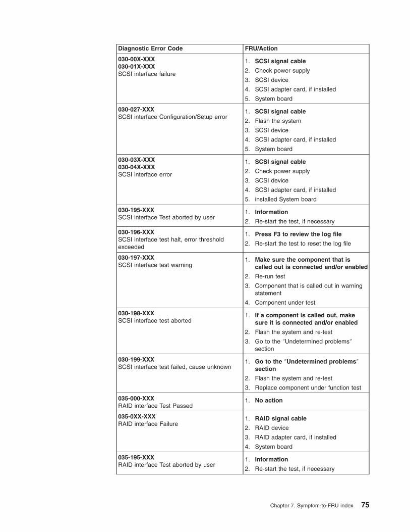
Diagnostic Error Code FRU/Action
030-00X-XXX
030-01X-XXX
SCSI interface failure
1. SCSI signal cable
2. Check power supply
3. SCSI device
4. SCSI adapter card, if installed
5. System board
030-027-XXX
SCSI interface Configuration/Setup error
1. SCSI signal cable
2. Flash the system
3. SCSI device
4. SCSI adapter card, if installed
5. System board
030-03X-XXX
030-04X-XXX
SCSI interface error
1. SCSI signal cable
2. Check power supply
3. SCSI device
4. SCSI adapter card, if installed
5. installed System board
030-195-XXX
SCSI interface Test aborted by user
1. Information
2. Re-start the test, if necessary
030-196-XXX
SCSI interface test halt, error threshold
exceeded
1. Press F3 to review the log file
2. Re-start the test to reset the log file
030-197-XXX
SCSI interface test warning
1. Make sure the component that is
called out is connected and/or enabled
2. Re-run test
3. Component that is called out in warning
statement
4. Component under test
030-198-XXX
SCSI interface test aborted
1. If a component is called out, make
sure it is connected and/or enabled
2. Flash the system and re-test
3. Go to the ″Undetermined problems″
section
030-199-XXX
SCSI interface test failed, cause unknown
1. Go to the ″Undetermined problems″
section
2. Flash the system and re-test
3. Replace component under function test
035-000-XXX
RAID interface Test Passed
1. No action
035-0XX-XXX
RAID interface Failure
1. RAID signal cable
2. RAID device
3. RAID adapter card, if installed
4. System board
035-195-XXX
RAID interface Test aborted by user
1. Information
2. Re-start the test, if necessary
Chapter 7. Symptom-to-FRU index 75

Diagnostic Error Code FRU/Action
035-196-XXX
RAID interface test halt, error threshold
exceeded
1. Press F3 to review the log file
2. Re-start the test to reset the log file
035-197-XXX
RAID interface test warning
1. Make sure the component that is
called out is connected and/or enabled
2. Re-run test
3. Component that is called out in warning
statement
4. Component under test
035-198-XXX
RAID interface test aborted
1. If a component is called out, make
sure it is connected and/or enabled
2. Flash the system and re-test
3. Go to the ″Undetermined problems″
section
035-199-XXX
RAID interface test failed, cause unknown
1. Go to the ″Undetermined problems″
section
2. Flash the system and re-test
3. Replace component under function test
071-000-XXX
Audio port Interface Test Passed
1. No action
071-00X-XXX
071-01X-XXX
071-02X-XXX Audio port error
1. Run Setup
2. Flash the system
3. System board
071-03X-XXX
Audio port failure
1. Speakers
2. Microphone
3. Audio card, if installed
4. System board
071-04X-XXX
Audio port failure
1. Run Setup
2. Audio card, if installed
3. System board
071-195-XXX
Audio port Test aborted by user
1. Information
2. Re-start the test, if necessary
071-196-XXX
Audio port test halt, error threshold exceeded
1. Press F3 to review the log file
2. Re-start the test to reset the log file
071-197-XXX
Audio port test warning
1. Make sure the component that is
called out is connected and/or enabled
2. Re-run test
3. Component that is called out in warning
statement
4. Component under test
071-198-XXX
Audio port test aborted
1. If a component is called out, make
sure it is connected and/or enabled
2. Flash the system and re-test
3. Go to the ″Undetermined problems″
section
76 Hardware Maintenance Manual: IBM IntelliStation Types 6849 and 6231

Diagnostic Error Code FRU/Action
071-199-XXX
Audio port test failed, cause unknown
1. Go to the ″Undetermined problems″
section
2. Flash the system and re-test
3. Replace component under function test
071-25X-XXX
Audio port failure
1. Speakers
2. Audio card, if installed
3. System board
080-000-XXX
Game Port interface Test Passed
1. No action
080-XXX-XXX
Game Port interface Error
1. Remove the game port device and
re-test the system
080-195-XXX
Game Port interface Test aborted by user
1. Information
2. Re-start the test, if necessary
080-196-XXX
Game Port interface test halt, error threshold
exceeded
1. Press F3 to review the log file
2. Re-start the test to reset the log file
080-197-XXX
Game Port interface test warning
1. Make sure the component that is
called out is connected and/or enabled
2. Re-run test
3. Component that is called out in warning
statement
4. Component under test
080-198-XXX
Game Port interface test aborted
1. If a component is called out, make
sure it is connected and/or enabled
2. Flash the system and re-test
3. Go to the ″Undetermined problems″
section
080-199-XXX
Game Port interface test failed, cause
unknown
1. Go to the ″Undetermined problems″
section
2. Flash the system and re-test
3. Replace component under function test
086-000-XXX
Mouse Port interface Test Passed
1. No action
086-001-XXX
Mouse Port interface Presence
1. Mouse
2. System board
086-032-XXX
Mouse Port interface Device controller failure
1. Mouse
2. System board
086-035-XXX
Mouse Port interface Reset
1. Mouse
2. System board
086-040-XXX
Mouse Port interface IRQ failure
1. Run Setup
2. Mouse
3. System board
086-195-XXX
Mouse Port interface Test aborted by user
1. Information
2. Re-start the test, if necessary
Chapter 7. Symptom-to-FRU index 77

Diagnostic Error Code FRU/Action
086-196-XXX
Mouse Port interface test halt, error threshold
exceeded
1. Press F3 to review the log file
2. Re-start the test to reset the log file
086-197-XXX
Mouse Port interface test warning
1. Make sure the component that is called
out is connected and/or enabled
2. Re-run test
3. Component that is called out in warning
statement
4. Component under test
086-198-XXX
Mouse Port interface test aborted
1. If a component is called out, make sure it
is connected and/or enabled
2. Flash the system and re-test
3. Go to the ″Undetermined problems″
section
086-199-XXX
Mouse Port interface test failed, cause
unknown
1. Go to the ″Undetermined problems″
section
2. Flash the system and re-test
3. Replace component under function test
089-000-XXX
Microprocessor Test Passed
1. No action
089-XXX-XXX
Microprocessor failure
1. Microprocessor(s)
2. System board
089-195-XXX
Microprocessor Test aborted by user
1. Information
2. Re-start the test, if necessary
089-196-XXX
Microprocessor test halt, error threshold
exceeded
1. Press F3 to review the log file
2. Re-start the test to reset the log file
089-197-XXX
Microprocessor test warning
1. Make sure the component that is
called out is connected and/or enabled
2. Re-run test
3. Component that is called out in warning
statement
4. Component under test
089-198-XXX
Microprocessor test aborted
1. Flash the system and re-test
2. Go to the ″Undetermined problems″
section
089-199-XXX
Microprocessor test failed, cause unknown
1. If a component is called out, make
sure it is connected and/or enabled
2. Go to the ″Undetermined problems″
section
3. Flash the system and re-test
4. Replace component under function test
170-000-XXX
Voltage Sensor(s) Test Passed
1. No action
170-0XX-XXX
Voltage Sensor(s) failure
1. Flash system
2. System board
78 Hardware Maintenance Manual: IBM IntelliStation Types 6849 and 6231

Diagnostic Error Code FRU/Action
170-195-XXX
Voltage Sensor(s) Test aborted by user
1. Information
2. Re-start the test, if necessary
170-196-XXX
Voltage Sensor(s) test halt, error threshold
exceeded
1. Press F3 to review the log file
2. Re-start the test to reset the log file
170-197-XXX
Voltage Sensor(s) test warning
1. Make sure the component that is
called out is connected and/or enabled
2. Re-run test
3. Component that is called out in warning
statement
4. Component under test
170-198-XXX
Voltage Sensor(s) test aborted
1. If a component is called out, make
sure it is connected and/or enabled
2. Flash the system and re-test
3. Go to the ″Undetermined problems″
section
170-199-XXX
Voltage Sensor(s) test failed, cause unknown
1. Go to the ″Undetermined problems″
section
2. Flash the system and re-test
3. Replace component under function test
170-250-XXX
170-251-XXX
Voltage Sensor(s) Voltage limit error
1. Power supply
2. System board
170-254-XXX
Voltage Sensor(s) Voltage Regulator Module
error
1. Voltage Regulator Module (VRM)
2. Microprocessor
3. System board
175-000-XXX
Thermal Sensor(s) Test Passed
1. No action
175-0XX-XXX
Thermal Sensor(s) failure
1. Flash system
2. System board
175-195-XXX
Thermal Sensor(s) Test aborted by user
1. Information
2. Re-start the test, if necessary
175-196-XXX
Thermal Sensor(s) test halt, error threshold
exceeded
1. Press F3 to review the log file
2. Re-start the test to reset the log file
175-197-XXX
Thermal Sensor(s) test warning
1. Make sure the component that is
called out is connected and/or enabled
2. Re-run test
3. Component that is called out in warning
statement
4. Component under test
175-198-XXX
Thermal Sensor(s) test aborted
1. If a component is called out, make
sure it is connected and/or enabled
2. Flash the system and re-test
3. Go to ″Undetermined problems″ section
Chapter 7. Symptom-to-FRU index 79

Diagnostic Error Code FRU/Action
175-199-XXX
Thermal Sensor(s) test failed, cause
unknown
1. Go to the ″Undetermined problems″
section
2. Flash the system and re-test
3. Replace component under function test
175-250-XXX
175-251-XXX
Thermal Sensor(s) limit error
1. Check fans
2. Check Power supply
3. Microprocessor
4. System board
185-000-XXX
Asset Security Test Passed
1. No action
185-XXX-XXX
Asset Security failure
1. Flash system
2. System board
185-278-XXX
Asset Security Chassis Intrusion
1. Assure Asset Security Enabled
2. C2 Cover Switch
3. System board
201-000-XXX
System Memory Test Passed
1. No action
201-XXX-XXX
System Memory error
1. Replace the memory module called
out by the test
2. System board
202-000-XXX
System Cache Test Passed
1. No action
202-XXX-XXX
System Cache error
1. Cache, if removable
2. System board
3. Microprocessor
206-000-XXX
Diskette Drive Test Passed
1. No action
206-XXX-XXX
Diskette Drive error
1. Diskette Drive Cable
2. Check power supply voltages
3. Diskette drive
4. System board
215-000-XXX
CD-ROM Drive Test Passed
1. No action
215-XXX-XXX
CD-ROM Drive error
1. CD-ROM Drive Cable
2. Check power supply voltages
3. CD-ROM drive
4. System board
217-000-XXX
Hard Disk Drive Test Passed
1. No action
217-25X-XXX
217-26X-XXX
Hard Disk Drive (IDE) error
1. Hard Disk Drive Cable
2. Check power supply voltages
3. Hard Disk drive (IDE)
4. System board
80 Hardware Maintenance Manual: IBM IntelliStation Types 6849 and 6231

Diagnostic Error Code FRU/Action
217-28X-XXX
217-29X-XXX
Hard Disk Drive (SCSI) error
1. Hard Disk Drive Cable
2. Check power supply voltages
3. Hard Disk drive (SCSI)
4. SCSI adapter card
5. System board
220-000-XXX
Hi-Capacity Cartridge Drive Test Passed
1. No action
220-XXX-XXX
Hi-Capacity Cartridge Drive error
1. Remove the Hi-Capacity Cartridge
Drive and re-test the system
301-XXX-XXX
Keyboard error
1. Keyboard
2. Check and test mouse
3. System board
301-000-XXX
Keyboard Test Passed
1. No action
302-000-XXX
Mouse Test Passed
1. No action
302-XXX-XXX
Mouse error
1. Mouse
2. Check and test Keyboard
3. System board
303-000-XXX
Joystick Test Passed
1. No action
303-XXX-XXX
Joystick error
1. Remove the Joystick and re-test the
system
305-000-XXX
Monitor DDC Test Passed
1. No action
305-250-XXX
Monitor DDC self test failure
1. Run Setup to enable DDC
2. Cable
3. Monitor
4. Video card
5. System board
415-000-XXXModem Test Passed
1. No action
415-XXX-XXX
Modem error
1. Remove the Modem and re-test the
system
POST error codes
Each time you power-on the system, it performs a series of tests that check the
operation of the system and some options. This series of tests is called the
Power-On Self-Test, or POST. POST does the following operations.
v Checks some basic system-board operations
v Checks the memory operation
v Starts the video operation
v Verifies that the diskette drive is working
v Verifies that the hard disk drive is working
Chapter 7. Symptom-to-FRU index 81

If the POST finishes without detecting any problems, a single beep sounds and the
first screen of the operating system or application program appears.
Note:
Type 6849 and 6231 computers default to come up quiet (no beep and no memory count
and checkpoint code display) when no errors are detected by POST.
To enable beep and memory count and checkpoint code display when a successful POST
occurs, do the following:
1. Select Start Options in the BIOS Setup Utility program (see “Using the BIOS Setup
Utility program” on page 19).
2. Set Power-On Self-Test to Enhanced.
If the POST detects a problem, an error message appears on the screen. A single
problem can cause several error messages to appear. When you correct the cause
of the first error message, the other error messages probably will not appear on the
screen the next time you turn on the system.
During the POST, the BIOS generates diagnostic progress codes (POST codes) to
I/O port 80h. If the POST fails, execution stops and the last POST code generated
is left at port 80h. This code is useful for determining the point where an error
occurred.
Displaying the POST codes requires an add-in card, often called a POST card (PCI,
not ISA). The POST card can decode the port and display the contents on a
medium such as a seven-segment display.
The table below offers descriptions of the POST codes generated by the BIOS.
Error Message FRU / Action
GA20 Error 1. Replace system board.
Pri Master HDD Error Pri Slave HDD
Error Sec Master HDD Error Sec Slave
HDD Error
1. Check/replace cables
2. Replace drive.
3. Replace system board.
Pri Master Drive -ATAPI Incompatible
Pri Slave Drive - ATAPI Incompatible
Sec Master Drive - ATAPI Incompatible
Sec Slave Drive - ATAPI Incompatible
1. Run setup to make sure drive is selected
correctly.
2. Replace drive.
A: Drive Error 1. Check/replace cables.
2. Replace drive.
3. Replace system board.
Cache Memory Bad 1. Replace CPU.
CMOS Battery Low 1. Replace battery.
2. Replace system board.
CMOS Display Type Wrong 1. Run setup and save.
2. Replace system board.
CMOS Checksum Bad 1. Check/change battery.
2. Run setup to reset value.
3. Replace system board.
82 Hardware Maintenance Manual: IBM IntelliStation Types 6849 and 6231

Error Message FRU / Action
CMOS Settings Wrong 1. Check battery.
2. Run setup.
3. Replace system board.
CMOS Date/Time Not Set 1. Check battery.
2. Run setup/set date and time.
3. Replace system board.
DMA Error 1. Check cables.
2. Run setup.
3. Replace system board.
FDC Failure 1. Check cables.
2. Run setup.
3. Replace system board.
HDC Failure 1. Check cables.
2. Run setup.
3. Replace system board.
Checking NVRAM... No action.
Update OK! No action.
Updated Failed 1. Check battery.
2. Replace system board.
Keyboard Error 1. Check keyboard connection.
2. Replace keyboard.
3. Replace system board.
KB/Interface Error 1. Run diagnostics.
2. Check keyboard.
3. Check mouse.
4. Replace keyboard.
5. Replace mouse.
6. Replace system board.
Memory Size Decreased/Changed 1. Reseat memory.
2. Run memory diagnostics.
3. Replace bad memory.
Memory Size Increased 1. Reseat memory.
2. Run memory diagnostics.
3. Replace bad memory, if any.
No Boot Device Available 1. Run setup and check boot sequence.
2. Cables.
3. Boot devices.
Off Board Parity Error 1. Run diagnostics.
2. Replace bad cards.
On Board Parity Error 1. Run diagnostics.
2. Replace system board.
Chapter 7. Symptom-to-FRU index 83
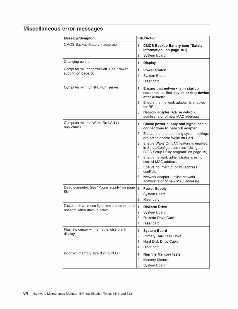
Miscellaneous error messages
Message/Symptom FRU/Action
CMOS Backup Battery inaccurate 1. CMOS Backup Battery (see “Safety
information” on page 101)
2. System Board
Changing colors 1. Display
Computer will not power-off. See “Power
supply” on page 56
1. Power Switch
2. System Board
3. Riser card
Computer will not RPL from server 1. Ensure that network is in startup
sequence as first device or first device
after diskette
2. Ensure that network adapter is enabled
for RPL
3. Network adapter (Advise network
administrator of new MAC address)
Computer will not Wake On LAN (if
applicable)
1. Check power supply and signal cable
connections to network adapter
2. Ensure that the operating system settings
are set to enable Wake on LAN
3. Ensure Wake On LAN feature is enabled
in Setup/Configuration (see “Using the
BIOS Setup Utility program” on page 19)
4. Ensure network administrator is using
correct MAC address
5. Ensure no interrupt or I/O address
conflicts
6. Network adapter (advise network
administrator of new MAC address)
Dead computer. See “Power supply” on page
56
1. Power Supply
2. System Board
3. Riser card
Diskette drive in-use light remains on or does
not light when drive is active.
1. Diskette Drive
2. System Board
3. Diskette Drive Cable
4. Riser card
Flashing cursor with an otherwise blank
display.
1. System Board
2. Primary Hard Disk Drive
3. Hard Disk Drive Cable
4. Riser card
Incorrect memory size during POST 1. Run the Memory tests
2. Memory Module
3. System Board
84 Hardware Maintenance Manual: IBM IntelliStation Types 6849 and 6231
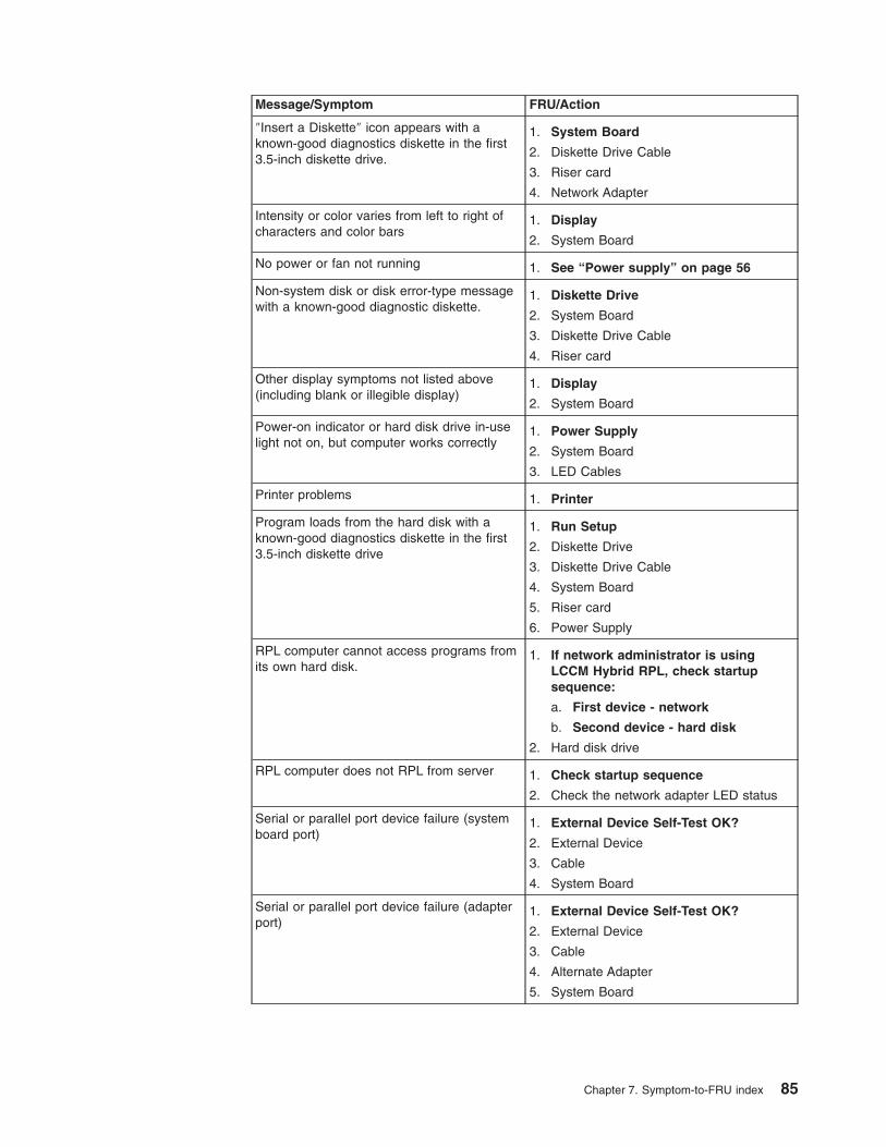
Message/Symptom FRU/Action
″Insert a Diskette″ icon appears with a
known-good diagnostics diskette in the first
3.5-inch diskette drive.
1. System Board
2. Diskette Drive Cable
3. Riser card
4. Network Adapter
Intensity or color varies from left to right of
characters and color bars
1. Display
2. System Board
No power or fan not running 1. See “Power supply” on page 56
Non-system disk or disk error-type message
with a known-good diagnostic diskette.
1. Diskette Drive
2. System Board
3. Diskette Drive Cable
4. Riser card
Other display symptoms not listed above
(including blank or illegible display)
1. Display
2. System Board
Power-on indicator or hard disk drive in-use
light not on, but computer works correctly
1. Power Supply
2. System Board
3. LED Cables
Printer problems 1. Printer
Program loads from the hard disk with a
known-good diagnostics diskette in the first
3.5-inch diskette drive
1. Run Setup
2. Diskette Drive
3. Diskette Drive Cable
4. System Board
5. Riser card
6. Power Supply
RPL computer cannot access programs from
its own hard disk.
1. If network administrator is using
LCCM Hybrid RPL, check startup
sequence:
a. First device - network
b. Second device - hard disk
2. Hard disk drive
RPL computer does not RPL from server 1. Check startup sequence
2. Check the network adapter LED status
Serial or parallel port device failure (system
board port)
1. External Device Self-Test OK?
2. External Device
3. Cable
4. System Board
Serial or parallel port device failure (adapter
port)
1. External Device Self-Test OK?
2. External Device
3. Cable
4. Alternate Adapter
5. System Board
Chapter 7. Symptom-to-FRU index 85

Message/Symptom FRU/Action
Some or all keys on the keyboard do not
work
1. Keyboard
2. Keyboard Cable
3. System Board
Undetermined problems
Damaged data in CMOS memory or damaged BIOS code can cause undetermined
problems. To reset the CMOS data, use the CMOS jumper to override the power-on
password and clear the CMOS memory; see “Erasing a lost or forgotten password
(clearing CMOS)” on page 14. If you suspect that the BIOS code is damaged, see
“Recovering from a POST/BIOS update failure” on page 15.
Check the power supply voltages (see “Power supply” on page 56). If the voltages
are correct, return here and continue with the following steps.
1. Power-off the computer.
2. Remove or disconnect the following components (if installed) one at a time.
a. Non-IBM devices
b. External devices (modem, printer, or mouse)
c. Any adapters
d. Memory modules. Before removing or replacing memory modules, see
“Installing memory modules” on page 38.
e. Extended video memory
f. External Cache
g. External Cache RAM
h. Hard disk drive
i. Diskette drive
3. Power-on the computer to re-test the system.
4. Repeat steps 1 through 3 until you find the failing device or adapter.
If all devices and adapters have been removed, and the problem continues, replace
the system board (see “Replacing a system board” on page 52).
Security features
Security features in this section include the following:
v Passwords
v Vital Product Data
v Management Information Format (MIF)
v Alert on LAN
Passwords
The following section provides information about computer hardware and
softwarerelated passwords.
v Power-on Password
v Administrator Password
v Operating System Password
86 Hardware Maintenance Manual: IBM IntelliStation Types 6849 and 6231

Power-on and Administrator passwords are set in the Setup Utility program. See
“Using the BIOS Setup Utility program” on page 19 for information about running
the Setup Utility.
Power-on password
A power-on password denies access to the computer by an unauthorized user when
the computer is powered on. When a power-on password is active, the password
prompt appears on the screen each time the computer is powered on. The
computer starts after the proper password is entered.
Removing a power-on password
To service a computer with an active and unknown power-on password, power-off
the computer and use the following procedure.
Note: On some models, this procedure will also remove the administrator password.
1. Unplug the power cord and remove the top cover.
2. Refer to “System board layout” on page 49 to find the recovery jumper.
3. Move the recovery jumper from normal to clear.
4. Power-on the computer. The system senses the change in the position and
erases the password. It is necessary to move the jumper back to the previous
position.
5. Remind the user to enter a new password when service is complete.
Administrator password
The administrator password is used to restrict access to the BIOS Setup Utility
program. If the administrator password is activated, and you do not enter the
administrator password, the configuration can be viewed but not changed.
Note: Type 6849 and 6231 computers have Enhanced Security Mode. If Enhanced
Security mode is enabled and there is no password given, the computer will act as if
Enhanced Security is disabled.
If Enhanced Security is Enabled and an administrator password is given, the administrator
password must be entered to use the computer. If the administrator password is lost or
forgotten, the system board in the computer must be replaced in order to regain access to
the BIOS Setup Utility program.
Administrator password control
The Administrator password is set in the Setup Configuration. Refer to “Using the
BIOS Setup Utility program” on page 19.
Operating system password
An operating system password is very similar to a power-on password and denies
access to the computer by an unauthorized user when the password is activated.
The computer is unusable until the password is entered and recognized by the
computer.
Vital product data
Each computer has a unique Vital Product Data (VPD) code stored in the
nonvolatile memory on the system board. After you replace the system board, the
VPD must be updated. To update the VPD, see “Flash (BIOS/VPD) update
procedure” on page 89.
Chapter 7. Symptom-to-FRU index 87

Management Information Format (MIF)
Management Information Format (MIF) is a file used to maintain a list of the system
unit serial number along with all serialized components (for example, system board,
riser card, memory, and processor).
At the time of computer manufacture, the EPROM will be loaded with the serial
numbers of the system and all major components. The customer will have access
to the MIF file via the DMI MIF Browser that is installed with the preload and is also
available on the SSCD that is provided with the system.
A company called Retain-a-Group is a central data warehouse offering serial
number data management. Retain-a-Group acts as a focal point to law
enforcement. The customer has the option to purchase serial number information
and services from Retain-a-Group. It is the customer’s responsibility to maintain the
MIF file and to inform Retain-a-Group of any changes to the file.
Some customers may request their servicers to assist them in maintaining the MIF
file when serialized components are replaced during hardware service. This
assistance is between the customer and the servicer. The servicer can use the DMI
MIF Browser to update the MIF information in the EPROM. It is anticipated that
some servicers might charge for this service.
To update the EPROM using the DMI MIF Browser, use the following procedure.
1. Click Start from the desktop, then Programs.
2. Select IBM SystemView Agent.
3. Select the Serial Number Information icon.
4. Click the plus sign to expand.
5. Select the component you want to view or edit.
6. Double click on the component you want to change.
7. Enter new data in the Value field, then click Apply.
Alert on LAN
Alert on LAN provides notification of changes in the computer, even when the
computer power is turned off. Working with DMI and Wake on LAN« technologies,
Alert on LAN helps to manage and monitor the hardware and software features of
the computer. Alert on LAN generates notifications to the server of these
occurrences:
v Computer disconnected from the network
v Computer unplugged from the power outlet
v All POST errors
v Operating system or POST hang condition
Alert on LAN events are configured to be Enabled or Disabled from the LAN server
only, and not from the computer. See the LAN administrator for configuration status
information.
88 Hardware Maintenance Manual: IBM IntelliStation Types 6849 and 6231

BIOS levels
An incorrect level of BIOS can cause false error and unnecessary FRU
replacement. Use the following information to determine the current level of BIOS
installed in the computer, the latest BIOS available for the computer, and where to
obtain the latest level of BIOS.
v Current Level BIOS information
– Run the Configuration Utility to determine the level of BIOS installed.
v Sources for determining the latest level BIOS available
1. IBM PC Company Home Page http://www.ibm.com/pc/us/
2. PC PartnerInfo-Technical Database (CTSTIPS.NSF)
3. HelpCenter®
4. Levels 1 and 2 Support
5. RETAIN®
v Sources for obtaining the latest level BIOS available
1. IBM PC Company Home Page http://www.ibm.com/pc/us/
2. PC PartnerInfo-Technical Database (CTSTIPS.NSF)
3. HelpCenter
4. Levels 1 and 2 Support
To update (flash) the BIOS, see “Flash (BIOS/VPD) update procedure.”
Flash (BIOS/VPD) update procedure
Attention: Refer to the information label located inside the system unit cover for any
model-specific information.
1. Power-off the computer.
2. Insert the flash update diskette into drive A.
3. Power-on the computer.
4. When the Update Utility appears; select the country/keyboard, then press Enter.
5. If the computer serial number was previously recorded, the number is displayed
with an option to update it. Press Y to update the serial number.
6. Type the 7-digit serial number of the computer you are servicing, then press
Enter.
7. Follow the instructions on the screen to complete the flash (BIOS/VPD) update
procedure.
Flash recovery boot block jumper
Attention: If an interruption occurs during a Flash/BIOS upgrade, the BIOS might be left
in an unusable state. The Boot Block jumper enables you to restart the system and recover
the BIOS.
To perform a Flash/BIOS recovery using the recovery jumper, use the following
procedure.
1. Power-off the computer and remove the cover.
2. Move the system board recovery jumper to the clear position. Refer to “System
board layout” on page 49 or the label inside the computer for more information.
Chapter 7. Symptom-to-FRU index 89

3. Insert the upgrade diskette into the diskette drive.
4. Power-on the computer. The IBM Logo will appear.
5. When the Flash Update Utility appears, select the country/keyboard, then press
Enter.
6. If the computer serial number was previously recorded, the number is displayed
with an option to update it. Press Y to update the serial number.
7. Type the 7-digit serial number of the computer you are servicing, then press
Enter.
8. Follow the instructions on the screen to complete the flash (BIOS/VPD) update
procedure.
9. When you are instructed to reboot the computer, power-off the computer and
move the recovery jumper to the normal position. Then replace the cover and
power-on the computer.
Power management
Power management reduces the power consumption of certain components of the
computer such as the system power supply, processor, hard disk drives, and some
monitors. Advanced Power Management and Rapid Resume™ Manager are
features of some personal computers.
Automatic configuration and power interface (ACPI) BIOS
Being an ACPI BIOS system, the operating system is allowed to control the power
management features of the computer and the setting for Advanced Power
Management (APM) BIOS mode are ignored. Not all operating systems support
ACPI BIOS mode.
Advanced Power Management
Energy-saving settings can be viewed and changed by using the Advanced Power
Management menu in the BIOS Setup Utility program.
Attention: If a device, such as a monitor, does not have power-management capabilities,
it can be damaged when exposed to a reduced-power state. Before making energy-saving
selections for the monitor, check the documentation supplied with the monitor to see if it
supports Display Power Management Signaling (DPMS).
Automatic Hardware Power Management features
Automatic Hardware Power Management can reduce the power states of the
computer, processor, and monitor (if the monitor supports DPMS) if they are
inactive for a predetermined length of time.
There are three levels of specified time that the computer must be inactive before
the power management options that are selected take effect. Select the amount of
time that is offered within each level.
Level 1 Set time from 5 minutes to 4 hours.
Level 2 Set time from 10 minutes to 5 hours.
Level 3 Set time from 15 minutes to 6 hours.
90 Hardware Maintenance Manual: IBM IntelliStation Types 6849 and 6231

At each level, you can define the amount of energy savings by specifying values for
the following options.
v System Power
– Select On for the computer to remain on.
– Select Off for the computer to shut down.
v Processor Speed
Set the microprocessor to be disabled, or to run at 1, 10, 25, or 50 percent of its
internal clock speed.
v Display
Set display to be disabled or to be reduced at these power states:
– Standby: Screen is blank, but can be restored immediately when any activity
is detected.
– Suspend: Monitor uses less power than in Standby mode. Screen image is
restored after a few seconds when any activity is detected.
– Off: Monitor power is off. Press Monitor power button to restore power. On
some monitors, you might have to depress the power button twice.
Setting Automatic Hardware Power Management features
1. Start the BIOS Setup Utility program (see “Using the BIOS Setup Utility
program” on page 19).
2. Select Advanced Power Management from the BIOS Setup Utility program
menu.
3. Select the APM BIOS Mode and be sure it is set to Enabled. If it is not, press
Left Arrow (<--) or Right Arrow ( -->) to change the setting.
4. Select Automatic Hardware Power Management.
5. Set Automatic Hardware Power Management to Enabled.
6. Select values for the three categories of power management (system power,
processor speed, and display), as necessary.
7. Set Hard Disk to Enabled or Disabled.
Note: This does not apply to SCSI drives.
8. Press Esc twice to return to the BIOS Setup Utility program menu.
9. Before you exit from the program, select Save Settings from the BIOS Setup
Utility program menu.
10. To exit from the BIOS Setup Utility program, press Esc and follow the
instructions on the screen.
Automatic Power-On features
The Automatic Power-On features within the Power Management menu allow you to
enable and disable features that turn on the computer automatically.
v Serial Port A Ring Detect: With this feature set to Enabled and an external
modem connected to serial port (COM1), the computer will turn on automatically
when a ring is detected on the modem.
v PCI Modem Ring Detect: With this feature set to Enabled , the computer will
turn on automatically when a ring is detected on the internal modem.
v PCI Wake Up: This feature allow PCI cards that support this capability to wake
the system.
Chapter 7. Symptom-to-FRU index 91

v Wake Up on Alarm: You can specify a date and time at which the computer will
be turned on automatically. This can be either a single event or a daily event.
v Wake on LAN: If the computer has a properly configured token-ring or Ethernet
LAN adapter card that is Wake on LAN-enabled and there is remote network
management software, you can use the IBM-developed Wake on LAN feature.
When you set Wake on LAN to Enabled, the computer will turn on when it
receives a specific signal from another computer on the local area network
(LAN). For further information, see “Wake on LAN” on page 93.
Network settings
This section applies only to computers that are linked to a network.
The BIOS Setup Utility program includes settings that can be enabled and disabled
to configure the network interface in the computer. These settings are the following:
v Flash over LAN (Update POST/BIOS over Network)
v Wake on LAN
Flash over LAN (update POST/BIOS over network)
Note: For local Flash (BIOS/VPD) update, see “Flash (BIOS/VPD) update
procedure” on page 89.
This setting is used to enable or disable the Flash over LAN feature. When the
feature is enabled, the system programs, in the computer, can be updated remotely
from a network server. If the administrator password is set in the computer, it does
not have to be entered by the server.
To access the Flash over LAN setting, use the following procedure.
1. Start the BIOS Setup Utility program. See “Using the BIOS Setup Utility
program” on page 19.
2. Select System Security.
3. Select POST/BIOS Update from the Configuration/Setup Utility program menu.
4. To enable Flash over LAN, select Enabled. To disable Flash over LAN, select
Disabled.
5. Press Esc twice to return to the BIOS Setup Utility program menu.
6. Before you exit from the program, select Save Settings from the BIOS Setup
Utility program menu.
7. To exit from the BIOS Setup Utility program, press Esc and follow the
instructions on the screen.
92 Hardware Maintenance Manual: IBM IntelliStation Types 6849 and 6231

Wake on LAN
This setting is used to enable or disable the IBM-developed Wake on LAN feature.
This feature makes it possible for the computer to be turned on remotely by a
network server. Remote network management software must be used in conjunction
with this feature.
To access the Wake on LAN setting, use the following procedure.
1. Start the BIOS Setup Utility program. See “Using the BIOS Setup Utility
program” on page 19.
2. Select Advanced Power Management.
3. Select Automatic Power On from the program menu.
4. Select Wake on LAN from the Automatic Power On menu.
5. To enable Wake on LAN, select Enabled. To disable Wake on LAN, select
Disabled.
6. Press Esc until you return to the BIOS Setup Utility program menu.
7. Before you exit from the program, select Save Settings from the BIOS Setup
Utility program menu.
8. To exit from the BIOS Setup Utility program, press Esc and follow the
instructions on the screen.
Chapter 7. Symptom-to-FRU index 93

94 Hardware Maintenance Manual: IBM IntelliStation Types 6849 and 6231
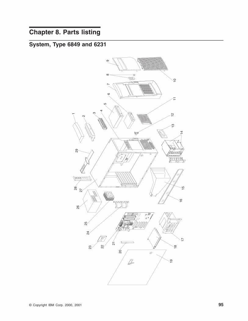
Chapter 8. Parts listing
System, Type 6849 and 6231
14
1
2
3
45
67
89
1011
1213
1516
17
1819
20
21
222324
25
2627
2829
© Copyright IBM Corp. 2000, 2001 95

This parts listing supports models10X, 12X, 13X, 15X, 16X, 20X, 22X, 23X, 25X,
26X, A0G, A2G, A3G, A5G, A6G, B0G, B2G, B3G, B5G, B6G, 1PU, 2PU.
Index System (IntelliStation – Type 6849 and 6231) FRU No.
1 Handle caps kit (All models) 19K4934
2 Support handle (All models) 19K4936
3 EMC shield for 5.25″ bay (All models) 19K5548
4 Chassis assembly (All models) 25P5111
5 48x CD-ROM (Primary) (All models) 33P3211
5 48x CD-ROM (Alternate) (All models) 06P5271
5 48x CD-ROM (Alternate) (All models) 19K1531
5 48x CD-ROM (Alternate) (All models) 19K1535
5 48x CD-ROM (Alternate) (All models) 24P3605
5 48x CD-ROM (Alternate) (All models) 33P3203
5 48x CD-ROM (Alternate) (All models) 33P3207
5 48x CD-ROM (Alternate) (All models) 33P3215
6 3.5″ 1.44MB floppy disk drive (Primary) (All models) 76H4091
6 3.5″ 1.44MB floppy disk drive (Alternate) (All models) 06P5227
6 3.5″ 1.44MB 3-mode floppy disk drive (Alternate) (All models) 06P5144
7 Front bezel assembly (All models) 25P5147
8 Power button kit (All models) 19K4940
9 Bezel door assembly (All models) 25P0543
10 Panel with icon (All models) 19K4942
11 EMC shield for 3.5″ bay (All models) 19K4943
12 Control panel assembly (All models) 19K4935
13 Speaker assembly (All models) 19K4929
14 I/O card edge retainer (All models) 19K4945
15 Fan duct assembly 25P4939
16 Support/Cam bracket assembly (All models) 19K4963
17 DASD rotating cage assembly (All models) 19K4931
18 18.2GB SCSI Hard disk drive (Primary) (Models 13X, 15X, 16X, 23X, 25X,
26X, A3G, A5G, A6G, B3G, B5G, B6G)
06P5365
18 18.2GB SCSI Hard disk drive (Alternate) (Models 13X, 15X, 16X, 23X, 25X,
26X, A3G, A5G, A6G, B3G, B5G, B6G)
19K1485
18 40.0GB Hard disk drive (Models 10X, 12X, 20X, 22X, A0G, A2G, B0G, B2G) 19K1568
19 Sliding door w/lock assembly (All models) 24P1752
20 128MB ECC RIMM (Models 10X, 12X, 20X, 22X, A0G, A2G, B0G, B2G) 33L3351
20 256MB ECC RIMM (Models 13X, 15X, 16X, 23X, 25X, 26X, 1PU, 2PU, A3G,
A5G, A6G, B3G, B5G, B6G)
33L3353
21 System board (All models) 33P2876
22 Processor fansink (All models) 32P4004
23 Processor 2.0 GHz with 512K-level cache (Models 10X, 12X, 13X, 15X, 16X,
1PU, A0G, A2G, A3G, A5G, A6G)
48P7205
23 Processor 2.2 GHz with 512K-level cache (Models 20X, 22X, 23X, 25X, 26X,
2PU, B0G, B2G, B3G, B5G, B6G)
48P7206
24 Card guide assembly (All models) 19K4947
25 Fan ASM 80mm ball bearing (Primary) (All models) 49P0286
25 Fan ASM 80mm ball bearing (Alternate) (All models) 22P4447
26 340 W Power supply (All models) 24P6898
27 Cover assembly, side & top (All models) 19K4957
28 EMC planar shield (All models) 49P1918
29 Bezel release bar (All models) 19K4946
Heatsink retainer module (All models) 24P4811
Retention clip (All models) 25P0867
Fan duct extension (All models) 32P0674
Service label (All models) 49P1925
96 Hardware Maintenance Manual: IBM IntelliStation Types 6849 and 6231

Index System (IntelliStation – Type 6849 and 6231) FRU No.
CD Audio cable (All models) 75H9219
Bezel blanks kit (All models) 00N7082
C2 switch assembly (All models) 09K9827
DASD Hard disk drive rail kit (All models) 23P1328
Dual USB cable (All models) 19K4964
FDD cable (All models) 76H4228
5-Drop SCSI cable (Models 13X, 15X, 16X, 23X, 25X, 26X, A3G, A5G, A6G,
B3G, B5G, B6G)
01K1549
DVI Dual VGA cable (Models 10X, 20X, 1PU, 2PU, A0G, B0G) 48P7583
VGA Pigtail cable (Models 12X, 13X, 22X, 23X, A2G, A3G, B2G, B3G) 48P7586
LED-Hard disk drive cable (Models 13X, 15X, 16X, 23X, 25X, 26X, A3G,
A5G, A6G, B3G, B5G, B6G)
76H7344
Foot kit (All models) 12J4506
Foot, snap-in (All models) 01N2196
Hardfile - ATA (2 drop) cable (Models 10X, 12X, 20X, 22X, A0G, A2G, B0G,
B2G)
37L5098
3V Lithium battery (All models) 33F8354
Lock assembly (All models) 24P1751
Memory continuity card (All models) 00N5223
Misc. hardware kit (includes: 7 M3.5 screws, 1 EMC gasket, 1 I/O blank
bracket, 1 power support bracket, 4 isolator brackets, 1 key holder bracket, 1
thumbcrew, 4 M3.5 slotted screws, 1 RFID clip, 4 planar spacers, 1 SCSI
cable clamp, 6 M3.5 slotted screws) (All models)
09N5764
Mouse, 3-button (All models) 76H6620
Power Cord (All models) 93F2364
Side panel with nameplate (All models) 19K4954
Dongle (Models 15X, 16X, 25X, 26X, A5G, A6G, B3G, B5G, B6G 09N3435
Ultra 160 SCSI adapter (Models 13X, 15X, 16X, 23X, 25X, 26X, A3G, A5G,
A6G, B3G, B5G, B6G)
06P2215
Video adapter, ATI Fire GL8800 (Models 15X, 25X, A5G, B5G) 25P6680
Video adapter, 3Dlabs Wildcat III 6110 (Models 16X, 26X, A6G, B6G) 25P6591
Video adapter, NVIDIAQuadro4 200NVS (Models 12X, 13X, 22X, 23X, A2G,
A3G, B2G, B3G)
25P6684
Video adapter, Matrox Millenium G450 (Models 10X, 20X, 1PU, 2PU, A0G,
B0G)
25P6691
Win 2000/NT Recovery CDs FRU No.
US English (All ″U″ models) 32P0536
UK English (All ″G″ models) 32P0537
AP English (All ″A″ models) 32P0538
French Canadian (All ″F″ models) 32P0539
French (All ″G″ models) 32P0540
German (All ″G″ models) 32P0541
Italian (All ″G″ models) 32P0542
Spanish (All ″G″ models) 32P0543
Dutch (All ″G″ models) 32P0544
Danish (All ″G″ models) 32P0545
Swedish (All ″G″ models) 32P0546
Norwegian (All ″G″ models) 32P0547
Finnish (All ″G″ models) 32P0548
Japan (All ″A″ models) 59P2812
China (All ″A″ models) 59P2813
Hong Kong (All ″A″ models) 59P2814
Taiwan (All ″A″ models) 59P2815
Chapter 8. Parts listing 97

Keyboards
Keyboard FRU No.
Arabic 37L2555
Belgium/French 37L2556
Belgium/UK 37L2557
Bulgarian 37L2558
Czech 37L2559
Chinese/US 37L2585
Danish 37L2560
Dutch 37L2561
French 37L2562
French Canadian 37L0913
French Canadian 37L2552
German 37L2563
Greek 37L2564
Hebrew 37L2565
Hungarian 37L2566
Korean 02K0901
LA Spanish 37L2553
Iceland 37L2567
Italy 37L2568
Norwegian 37L2569
Polish 37L2570
Portuguese 37L2571
Romanian 37L2572
Russian 37L2573
Serbian/Cyrillic 37L2574
Slavic 37L2575
Spanish 37L2576
Swedish/Finn 37L2577
Swiss, F/G 37L2578
Thailand 37L2587
Turkish 37L2579
Turkish 37L2580
UK English 37L2581
US English 37L2551
US English-EMEA 37L2583
Yugosl/Lat 37L2582
Power cords
Power cord FRU No.
China (PRC) 01K9851
Japan 01K9853
Thailand 12J5120
Israel 12J5122
Bangladesh, Burma, India, Pakistan, South Africa, Sri Lanka 12J5124
Chile, Ethiopia, Italy, Libya, Somalia 12J5126
Argentina, Australia, New Zealand, Papua New Guinea, Paraguay, Uruguay, Western
Samoa
12J5128
Antigua, Bahrain, Brunei, Channel Islands, Cyprus, Dubai, Fiji, Ghana, Hong Kong,
Iraq, Ireland, Kenya, Kuwait, Malawi, Malaysia, Malta, Nepal, Nigeria, Polynesia,
Qatar, Sierra Leone, Singapore, Tanzania, Uganda, United Kingdom, Yemen, Zambia
12J5987
98 Hardware Maintenance Manual: IBM IntelliStation Types 6849 and 6231

Power cord FRU No.
Afghanistan, Algeria, Andorra, Angola, Austria, Belgium, Benin, Bulgaria, Burkina Faso,
Burundi, Cameroon, Central African Rep., Chad, Czech Republic, Egypt, Finland,
France, French Guiana, Germany, Greece, Guinea, Hungary, Iceland, Indonesia, Iran,
Ivory Coast, Jordan, Lebanon, Luxembourg, Macau, Malagasy, Mali, Martinique,
Mauritania, Mauritius, Monaco, Morocco, Mozambique, Netherlands, New Caledonia,
Niger, Norway, Poland, Portugal, Romania, Senegal, Slovakia, Spain, Sudan, Sweden,
Syria, Togo, Tunisia, Turkey, former USSR, Vietnam, former Yugoslavia, Zaire,
Zimbabwe
55H6643
Denmark, Switzerland, Liechtenstein 55H6646
Bahamas, Barbados, Bermuda, Bolivia, Brazil, Canada, Cayman Islands, Colombia,
Costa Rica, Dominican Republic, Ecuador, El Salvador, Guatemala, Guyana, Haiti,
Honduras, Jamaica, Korea (South), Liberia, Mexico, Netherlands Antilles, Nicaragua,
Panama, Peru, Philippines, Saudi Arabia, Suriname, Taiwan, Trinidad (West Indies),
Venezuela
76H4865
United States of America 6952301 (110) 1838574 (220)
36L8886 (220V/15A)
Chapter 8. Parts listing 99

100 Hardware Maintenance Manual: IBM IntelliStation Types 6849 and 6231

Chapter 9. Related service information
Note: The service procedures are designed to help you isolate problems. They are
written with the assumption that you have model-specific training on all
computers, or that are familiar with the computers, functions, terminology,
and service information provided in this manual.
Safety information
The following section contains the safety information that you need to be familiar
with before servicing an IBM computer.
General safety
Follow these rules to ensure general safety:
v Observe good housekeeping in the area of the machines during and after
maintenance.
v When lifting any heavy object:
1. Ensure you can stand safely without slipping.
2. Distribute the weight of the object equally between your feet.
3. Use a slow lifting force. Never move suddenly or twist when you attempt to
lift.
4. Lift by standing or by pushing up with your leg muscles; this action removes
the strain from the muscles in your back. Do not attempt to lift any objects
that weigh more than 16 kg (35 lb) or objects that you think are too heavy for
you.
v Do not perform any action that causes hazards to the customer, or that makes
the equipment unsafe.
v Before you start the machine, ensure that other service representatives and the
customer’s personnel are not in a hazardous position.
v Place removed covers and other parts in a safe place, away from all personnel,
while you are servicing the machine.
v Keep your tool case away from walk areas so that other people will not trip over
it.
v Do not wear loose clothing that can be trapped in the moving parts of a machine.
Ensure that your sleeves are fastened or rolled up above your elbows. If your
hair is long, fasten it.
v Insert the ends of your necktie or scarf inside clothing or fasten it with a
nonconductive clip, approximately 8 centimeters (3 inches) from the end.
v Do not wear jewelry, chains, metal-frame eyeglasses, or metal fasteners for your
clothing.
Remember: Metal objects are good electrical conductors.
v Wear safety glasses when you are: hammering, drilling soldering, cutting wire,
attaching springs, using solvents, or working in any other conditions that might be
hazardous to your eyes.
v After service, reinstall all safety shields, guards, labels, and ground wires.
Replace any safety device that is worn or defective.
v Reinstall all covers correctly before returning the machine to the customer.
© Copyright IBM Corp. 2000, 2001 101

Electrical safety
CAUTION:
Electrical current from power, telephone, and communication cables can be
hazardous. To avoid personal injury or equipment damage, disconnect the
attached power cords, telecommunication systems, networks, and modems
before you open the computer covers, unless instructed otherwise in the
installation and configuration procedures.
Observe the following rules when working on electrical equipment.
Important: Use only approved tools and test equipment. Some hand tools have
handles covered with a soft material that does not insulate you when
working with live electrical currents.
Many customers have, near their equipment, rubber floor mats that
contain small conductive fibers to decrease electrostatic discharges. Do
not use this type of mat to protect yourself from electrical shock.
v Find the room emergency power-off (EPO) switch, disconnecting switch, or
electrical outlet. If an electrical accident occurs, you can then operate the switch
or unplug the power cord quickly.
v Do not work alone under hazardous conditions or near equipment that has
hazardous voltages.
v Disconnect all power before:
– Performing a mechanical inspection
– Working near power supplies
– Removing or installing main units
v Before you start to work on the machine, unplug the power cord. If you cannot
unplug it, ask the customer to power-off the wall box that supplies power to the
machine and to lock the wall box in the off position.
v If you need to work on a machine that has exposed electrical circuits, observe
the following precautions:
– Ensure that another person, familiar with the power-off controls, is near you.
Remember: Another person must be there to switch off the power, if
necessary.
– Use only one hand when working with powered-on electrical equipment; keep
the other hand in your pocket or behind your back.
Remember: There must be a complete circuit to cause electrical shock. By
observing the above rule, you may prevent a current from passing through
your body.
– When using testers, set the controls correctly and use the approved probe
leads and accessories for that tester.
– Stand on suitable rubber mats (obtained locally, if necessary) to insulate you
from grounds such as metal floor strips and machine frames.
Observe the special safety precautions when you work with very high voltages;
these instructions are in the safety sections of maintenance information. Use
extreme care when measuring high voltages.
v Regularly inspect and maintain your electrical hand tools for safe operational
condition.
102 Hardware Maintenance Manual: IBM IntelliStation Types 6849 and 6231

v Do not use worn or broken tools and testers.
v Never assume that power has been disconnected from a circuit. First, check that
it has been powered-off.
v Always look carefully for possible hazards in your work area. Examples of these
hazards are moist floors, nongrounded power extension cables, power surges,
and missing safety grounds.
v Do not touch live electrical circuits with the reflective surface of a plastic dental
mirror. The surface is conductive; such touching can cause personal injury and
machine damage.
v Do not service the following parts with the power on when they are removed from
their normal operating places in a machine:
– Power supply units
– Pumps
– Blowers and fans
– Motor generators and similar units. (This practice ensures correct grounding of
the units.)
v If an electrical accident occurs:
– Use caution; do not become a victim yourself.
– Switch off power.
– Send another person to get medical aid.
Safety inspection guide
The intent of this inspection guide is to assist you in identifying potentially unsafe
conditions on these products. Each machine, as it was designed and built, had
required safety items installed to protect users and service personnel from injury.
This guide addresses only those items. However, good judgment should be used to
identify potential safety hazards due to attachment of non-IBM features or options
not covered by this inspection guide.
If any unsafe conditions are present, you must determine how serious the apparent
hazard could be and whether you can continue without first correcting the problem.
Consider these conditions and the safety hazards they present:
v Electrical hazards, especially primary power (primary voltage on the frame can
cause serious or fatal electrical shock).
v Explosive hazards, such as a damaged CRT face or bulging capacitor
v Mechanical hazards, such as loose or missing hardware
The guide consists of a series of steps presented in a checklist. Begin the checks
with the power off, and the power cord disconnected.
Checklist:
1. Check exterior covers for damage (loose, broken, or sharp edges).
2. Power-off the computer. Disconnect the power cord.
Chapter 9. Related service information 103

3. Check the power cord for:
a. A third-wire ground connector in good condition. Use a meter to measure
third-wire ground continuity for 0.1 ohm or less between the external ground
pin and frame ground.
b. The power cord should be the appropriate type as specified in the parts
listings.
c. Insulation must not be frayed or worn.
4. Remove the cover.
5. Check for any obvious non-IBM alterations. Use good judgment as to the safety
of any non-IBM alterations.
6. Check inside the unit for any obvious unsafe conditions, such as metal filings,
contamination, water or other liquids, or signs of fire or smoke damage.
7. Check for worn, frayed, or pinched cables.
8. Check that the power-supply cover fasteners (screws or rivets) have not been
removed or tampered with.
Handling static sensitive devices
Any computer part containing transistors or integrated circuits (ICs) should be
considered sensitive to electrostatic discharge (ESD). ESD damage can occur when
there is a difference in charge between objects. Protect against ESD damage by
equalizing the charge so that the machine, the part, the work mat, and the person
handling the part are all at the same charge.
Notes:
1. Use product-specific ESD procedures when they exceed the requirements
noted here.
2. Make sure that the ESD protective devices you use have been certified (ISO
9000) as fully effective.
When handling ESD-sensitive parts:
v Keep the parts in protective packages until they are inserted into the product.
v Avoid contact with other people.
v Wear a grounded wrist strap against your skin to eliminate static on your body.
v Prevent the part from touching your clothing. Most clothing is insulative and
retains a charge even when you are wearing a wrist strap.
v Use the black side of a grounded work mat to provide a static-free work surface.
The mat is especially useful when handling ESD-sensitive devices.
v Select a grounding system, such as those listed below, to provide protection that
meets the specific service requirement.
Note: The use of a grounding system is desirable but not required to protect
against ESD damage.
– Attach the ESD ground clip to any frame ground, ground braid, or green-wire
ground.
– Use an ESD common ground or reference point when working on a
double-insulated or battery-operated system. You can use coax or
connector-outside shells on these systems.
– Use the round ground-prong of the ac plug on ac-operated computers.
104 Hardware Maintenance Manual: IBM IntelliStation Types 6849 and 6231

Grounding requirements
Electrical grounding of the computer is required for operator safety and correct
system function. Proper grounding of the electrical outlet can be verified by a
certified electrician.
Safety notices (multi-lingual translations)
The caution and danger safety notices in this section are provided in the following
languages:
v English
v Brazilian/Portuguese
v Chinese
v French
v German
v Italian
v Korean
v Spanish
Important: All caution and danger statements in this section begin with a number.
This number is used to cross reference an English caution or danger
statement with translated versions of the caution or danger statement in
this section.
For example, if a caution statement begins with a number 1,
translations for that caution statement appear in this section under
statement 1.
Be sure to read all caution and danger statements before performing
any of the instructions.
v Statement 1
DANGER
Electrical current from power, telephone and communication cables is hazardous.
To avoid a shock hazard:
v Do not connect or disconnect any cables or perform installation,
maintenance, or reconfiguration of this product during an electrical storm.
v Connect all power cords to a properly wired and grounded electrical outlet.
v Connect to properly wired outlets any equipment that will be attached to
this product.
v When possible, use one hand only to connect or disconnect signal cables.
v Never turn on any equipment when there is evidence of fire, water, or
structural damage.
v Disconnect the attached power cords, telecommunications systems,
networks, and modems before you open the device covers, unless
instructed otherwise in the installation and configuration procedures.
Chapter 9. Related service information 105

v Connect and disconnect cables as described in the following table when
installing, moving, or opening covers on this product or attached devices.
To Connect To Disconnect
1. Turn everything OFF.
2. First, attach all cables to devices.
3. Attach signal cables to connectors.
4. Attach power cords to outlet.
5. Turn device ON.
1. Turn everything OFF.
2. First, remove power cords from outlet.
3. Remove signal cables from connectors.
4. Remove all cables from devices.
v Statement 2
CAUTION:
When replacing the lithium battery, use only IBM Part Number 33F8354 or an
equivalent type battery recommended by the manufacturer. If your system has
a module containing a lithium battery, replace it only with the same module
type made by the same manufacturer. The battery contains lithium and can
explode if not properly used, handled, or disposed of.
Do not:
v Throw or immerse into water
v Heat to more than 100°C (212°F)
v Repair or disassemble
Dispose of the battery as required by local ordinances or regulations.
v Statement 3
CAUTION:
When laser products (such as CD-ROMs, DVD-ROM drives, fiber optic
devices, or transmitters) are installed, note the following:
v Do not remove the covers. Removing the covers of the laser product could
result in exposure to hazardous laser radiation. There are no serviceable
parts inside the device.
v Use of controls or adjustments or performance of procedures other than
those specified herein might result in hazardous radiation exposure.
106 Hardware Maintenance Manual: IBM IntelliStation Types 6849 and 6231

DANGER
Some laser products contain an embedded Class 3A or Class 3B laser
diode. Note the following.
Laser radiation when open. Do not stare into the beam, do not view directly
with optical instruments, and avoid direct exposure to the beam.
Some laser products contain an embedded Class 3A or Class 3B laser diode.
Note the following:
Laser radiation when open. Do not stare into the beam, do not view directly
with optical instruments, and avoid direct exposure to the beam.
v Statement 4
≥18 kg (37 lbs) ≥32 kg (70.5 lbs) ≥55 kg (121.2 lbs)
CAUTION:
Use safe practices when lifting.
v Statement 5
CAUTION:
The power control button on the device and the power switch on the power
supply do not turn off the electrical current supplied to the device. The device
also might have more than one power cord. To remove all electrical current
from the device, ensure that all power cords are disconnected from the power
source.
1
2
Chapter 9. Related service information 107
v Statement 10
CAUTION:
Do not place any object weighing more than 82 kg (180 lbs.) on top of
rack-mounted devices.
Importante:
Todas as instruções de cuidado e perigo da Netfinity Server Library começam com
um número. Este número é utilizado para fazer referência cruzada de uma
instrução de cuidado ou perigo no idioma inglês com as versões traduzidas das
instruções de cuidado ou perigo encontradas nesta seção.
Por exemplo, se uma instrução de cuidado é iniciada com o número 1, as
traduções para aquela instrução de cuidado aparecem nesta seção sob a instrução
1.
Certifique-se de ler todas as instruções de cuidado e perigo antes de executar
qualquer operação.
Instrução 1
PERIGO
A corrente elétrica proveniente de cabos de alimentação, de telefone e de
comunicações é perigosa.
Para evitar risco de choque:
v Não conecte ou desconecte cabos e não realize instalação, manutenção ou
reconfiguração deste produto durante uma tempestade com raios.
v Conecte todos os cabos de alimentação a tomadas elétricas corretamente
instaladas e aterradas.
v Conecte todos os equipamentos ao qual esse produto será conectado a tomadas
corretamente instaladas.
v Sempre que possível, utilize apenas uma das mãos para conectar ou
desconectar cabos de sinal.
v Nunca ligue qualquer equipamento quando existir evidência de danos por fogo,
água ou na estrutura.
v Desconecte cabos de alimentação, sistemas de telecomunicação, redes e
modems antes de abrir as tampas dos dispositivos, a menos que especificado
de maneira diferente nos procedimentos de instalação e configuração.
v Conecte e desconecte cabos conforme descrito na seguinte tabela, ao instalar
ou movimentar este produto ou os dispositivos conectados, ou ao abrir suas
tampas.
108 Hardware Maintenance Manual: IBM IntelliStation Types 6849 and 6231

Para Conectar: Para Desconectar:
1. DESLIGUE Tudo.
2. Primeiramente, conecte todos os cabos
aos dispositivos.
3. Conecte os cabos de sinal aos
conectores.
4. Conecte os cabos de alimentação às
tomadas.
5. LIGUE os dispositivos.
1. DESLIGUE Tudo.
2. Primeiramente, remova os cabos de
alimentação das tomadas.
3. Remova os cabos de sinal dos
conectores.
4. Remova todos os cabos dos dispositivos.
Instrução 2
CUIDADO:
Ao substituir a bateria de lítio, utilize apenas uma bateria IBM, Número de Peça
33F8354 ou uma bateria de tipo equivalente, recomendada pelo fabricante. Se o
seu sistema possui um móídulo com uma bateria de lítio, substitua-o apenas pelo
mesmo tipo de mídulo, do mesmo fabricante. A bateria contém lítio e pode explodir
se não for utilizada, manuseada e descartada de maneira correta.
Não:
v Jogue ou coloque na água
v Aqueça a mais de 100° C (212° F)
v Conserte nem desmonte
Para descartar a bateria, entre em contato com a área de atendimento a clientes
IBM, pelo telefone (011) 889-8986, para obter informações sobre como enviar a
bateria pelo correio para a IBM.
Instrução 3
PRECAUCIÓN:
Quando produtos a laser (unidades de CD-ROM, unidades de DVD, dispositivos de
fibra ítica, transmissores, etc.) estiverem instalados, observe o seguinte:
v Não remova as tampas. A remoção das tampas de um produto a laser pode
resultar em exposição prejudicial à radiação de laser. Nenhuma peça localizada
no interior do dispositivo pode ser consertada.
v A utilização de controles ou ajustes ou a execução de procedimentos diferentes
dos especificados aqui pode resultar em exposição prejudicial à radiação.
PERIGO
Alguns produtos a laser contêm um diodo laser da Classe 3A ou Classe 3B
embutido. Observe o seguinte:
Chapter 9. Related service information 109
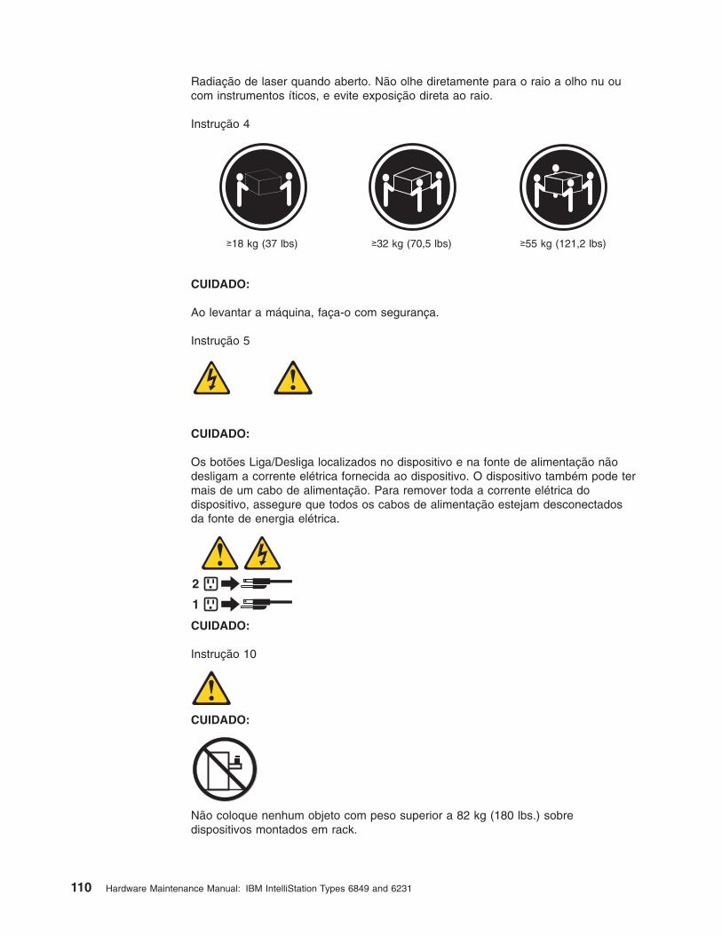
Radiação de laser quando aberto. Não olhe diretamente para o raio a olho nu ou
com instrumentos íticos, e evite exposição direta ao raio.
Instrução 4
≥18 kg (37 lbs) ≥32 kg (70,5 lbs) ≥55 kg (121,2 lbs)
CUIDADO:
Ao levantar a máquina, faça-o com segurança.
Instrução 5
CUIDADO:
Os botões Liga/Desliga localizados no dispositivo e na fonte de alimentação não
desligam a corrente elétrica fornecida ao dispositivo. O dispositivo também pode ter
mais de um cabo de alimentação. Para remover toda a corrente elétrica do
dispositivo, assegure que todos os cabos de alimentação estejam desconectados
da fonte de energia elétrica.
1
2
CUIDADO:
Instrução 10
CUIDADO:
Não coloque nenhum objeto com peso superior a 82 kg (180 lbs.) sobre
dispositivos montados em rack.
110 Hardware Maintenance Manual: IBM IntelliStation Types 6849 and 6231

Chapter 9. Related service information 111

112 Hardware Maintenance Manual: IBM IntelliStation Types 6849 and 6231

Chapter 9. Related service information 113

114 Hardware Maintenance Manual: IBM IntelliStation Types 6849 and 6231

Chapter 9. Related service information 115

116 Hardware Maintenance Manual: IBM IntelliStation Types 6849 and 6231

Important:
Toutes les consignes Attention et Danger indiquées dans la bibliothèque Netfinity
Server sont précédées d’un numéro. Ce dernier permet de mettre en
correspondance la consigne en anglais avec ses versions traduites dans la
présente section.
Par exemple, si une consigne de type Attention est précédée du chiffre 1, ses
traductions sont également précédées du chiffre 1 dans la présente section.
Prenez connaissance de toutes les consignes de type Attention et Danger avant de
procéder aux opérations décrites par les instructions.
Notice n° 1
DANGER
Le courant électrique passant dans les câbles de communication, ou les cordons
téléphoniques et d’alimentation peut être dangereux.
Pour éviter tout risque de choc électrique:
v Ne manipulez aucun câble et n’effectuez aucune opération d’installation,
d’entretien ou de reconfiguration de ce produit au cours d’un orage.
Chapter 9. Related service information 117
v Branchez tous les cordons d’alimentation sur un socle de prise de courant
correctement câblé et mis à la terre.
v Branchez sur des socles de prise de courant correctement câblés tout
équipement connecté à ce produit.
v Lorsque cela est possible, n’utilisez qu’une seule main pour connecter ou
déconnecter les câbles d’interface.
v Ne mettez jamais un équipement sous tension en cas d’incendie ou d’inondation,
ou en présence de dommages matériels.
v Avant de retirer les carters de l’unité, mettez celle-ci hors tension et déconnectez
ses cordons d’alimentation, ainsi que les câbles qui la relient aux réseaux, aux
systèmes de télécommunication et aux modems (sauf instruction contraire
mentionnée dans les procédures d’installation et de configuration).
v Lorsque vous installez ou que vous déplacez le présent produit ou des
périphériques qui lui sont raccordés, reportez-vous aux instructions ci-dessous
pour connecter et déconnecter les différents cordons.
Connexion Déconnexion
1. Mettez les unités hors tension.
2. Commencez par brancher tous les
cordons sur les unités.
3. Branchez les câbles d’interface sur des
connecteurs.
4. Branchez les cordons d’alimentation sur
des prises.
5. Mettez les unités sous tension.
1. Mettez les unités hors tension.
2. Débranchez les cordons d’alimentation
des prises.
3. Débranchez les câbles d’interface des
connecteurs.
4. Débranchez tous les câbles des unités.
Notice n° 2
ATTENTION:
Remplacez la pile au lithium usagée par une pile de référence identique
exclusivement - voir la référence IBM - ou par une pile équivalente
recommandée par le fabricant. Si votre système est doté d’un module
contenant une pile au lithium, vous devez le remplacer uniquement par un
module identique, produit par le même fabricant. La pile contient du lithium et
présente donc un risque d’explosion en cas de mauvaise manipulation ou
utilisation.
v Ne la jetez pas à l’eau.
v Ne l’exposez pas à une température supérieure à 100 °C.
v Ne cherchez pas à la réparer ou à la démonter.
Pour la mise au rebut, reportez-vous à la réglementation en vigueur.
Notice n° 3
ATTENTION:
118 Hardware Maintenance Manual: IBM IntelliStation Types 6849 and 6231

Si des produits laser sont installés (tels que des unités de CD-ROM ou de
DVD, des périphériques contenant des fibres optiques ou des
émetteurs-récepteurs), prenez connaissance des informations suivantes:
v N’ouvrez pas ces produits pour éviter une exposition directe au rayon
laser. Vous ne pouvez effectuer aucune opération de maintenance à
l’intérieur.
v Pour éviter tout risque d’exposition au rayon laser, respectez les consignes
de réglage et d’utilisation des commandes, ainsi que les procédures
décrites dans le présent document.
DANGER
Certains produits laser contiennent une diode laser de classe 3A ou 3B.
Prenez connaissance des informations suivantes:
Rayonnement laser lorsque le carter est ouvert. évitez de regarder fixement le
faisceau ou de l’observer à l’aide d’instruments optiques. évitez une
exposition directe au rayon.
Notice n° 4
≥18 kg ≥32 kg ≥55 kg
ATTENTION:
Faites-vous aider pour soulever ce produit.
Notice n° 5
ATTENTION:
Le bouton de mise sous tension/hors tension de l’unité et l’interrupteur
d’alimentation du bloc d’alimentation ne coupent pas l’arrivée de courant
électrique à l’intérieur de la machine. Il se peut que votre unité dispose de
plusieurs cordons d’alimentation. Pour isoler totalement l’unité du réseau
électrique, débranchez tous les cordons d’alimentation des socles de prise de
courant.
Chapter 9. Related service information 119

1
2
Notice n° 10
ATTENTION:
Ne posez pas d’objet dont le poids dépasse 82 kg sur les unités montées en
armoire.
Wichtig:
Alle Sicherheitshinweise in dieser Netfinity Server-Bibliothek beginnen mit einer
Nummer. Diese Nummer verweist auf einen englischen Sicherheitshinweis mit den
übersetzten Versionen dieses Hinweises in diesem Abschnitt.
Wenn z. B. ein Sicherheitshinweis mit der Nummer 1 beginnt, so erscheint die
übersetzung für diesen Sicherheitshinweis in diesem Abschnitt unter dem Hinweis
1.
Lesen Sie alle Sicherheitshinweise, bevor Sie eine Anweisung ausführen.
Hinweis 1
VORSICHT
Elektrische Spannungen von Netz-, Telefon- und Datenübertragungsleitungen sind
gefährlich.
Aus Sicherheitsgründen:
v Bei Gewitter an diesem Gerät keine Kabel anschließen oder lösen. Ferner keine
Installations-, Wartungs- oder Rekonfigurationsarbeiten durchführen.
v Gerät nur an eine Schutzkontaktsteckdose mit ordnungsgemäß geerdetem
Schutzkontakt anschließen.
v Alle angeschlossenen Geräte ebenfalls an Schutzkontaktsteckdosen mit
ordnungsgemäß geerdetem Schutzkontakt anschließen.
v Signalkabel möglichst einhändig anschließen oder lösen.
120 Hardware Maintenance Manual: IBM IntelliStation Types 6849 and 6231

v Keine Geräte einschalten, wenn die Gefahr einer Beschädigung durch Feuer,
Wasser oder andere Einflüsse besteht.
v Die Verbindung zu den angeschlossenen Netzkabeln,
Telekommunikationssystemen, Netzwerken und Modems ist vor dem öffnen des
Gehäuses zu unterbrechen. Es sei denn, dies ist in den zugehörigen
Installations- und Konfigurationsprozeduren anders angegeben.
v Nur nach den nachfolgend aufgeführten Anweisungen arbeiten, die für
Installation, Transport oder öffnen von Gehäusen von Personal Computern oder
angeschlossenen Einheiten gelten.
Kabel anschlieβen: Kabel lösen:
1. Alle Geräte ausschalten und
Netzstecker ziehen.
2. Zuerst alle Kabel an Einheiten
anschließen.
3. Signalkabel an Anschlußbuchsen
anschließen.
4. Netzstecker an Steckdose anschließen.
5. Gerät einschalten.
1. Alle Geräte ausschalten.
2. Zuerst Netzstecker von Steckdose lösen.
3. Signalkabel von Anschlußbuchsen lösen.
4. Alle Kabel von Einheiten lösen.
Hinweis 2
ACHTUNG:
Eine verbrauchte Batterie nur durch eine Batterie mit der IBM Teilenummer
33F8354 oder durch eine vom Hersteller empfohlene Batterie ersetzen. Wenn Ihr
System ein Modul mit einer Lithium-Batterie enthält, ersetzen Sie es immer mit dem
selben Modultyp vom selben Hersteller. Die Batterie enthält Lithium und kann bei
unsachgemäßer Verwendung, Handhabung oder Entsorgung explodieren.
Die Batterie nicht:
v mit Wasser in Berührung bringen.
v über 100 C erhitzen.
v reparieren oder zerlegen.
Die örtlichen Bestimmungen für die Entsorgung von Sondermüll beachten.
Hinweis 3
ACHTUNG:
Wenn ein Laserprodukt (z. B. CD-ROM-Laufwerke, DVD-Laufwerke, Einheiten mit
Glasfaserkabeln oder Transmitter) installiert ist, beachten Sie folgendes.
v Das Entfernen der Abdeckungen des CD-ROM-Laufwerks kann zu gefährlicher
Laserstrahlung führen. Es befinden sich keine Teile innerhalb des
CD-ROM-Laufwerks, die vom Benutzer gewartet werden müssen. Die
Verkleidung des CD-ROM-Laufwerks nicht öffnen.
Chapter 9. Related service information 121

v Steuer- und Einstellelemente sowie Verfahren nur entsprechend den
Anweisungen im vorliegenden Handbuch einsetzen. Andernfalls kann gefährliche
Laserstrahlung auftreten.
VORSICHT
Manche CD-ROM-Laufwerke enthalten eine eingebaute Laserdiode der Klasse 3A
oder 3B. Die nachfolgend aufgeführten Punkte beachten.
Laserstrahlung bei geöffneter Tür. Niemals direkt in den Laserstrahl sehen, nicht
direkt mit optischen Instrumenten betrachten und den Strahlungsbereich meiden.
Hinweis 4
≥18 kg ≥32 kg ≥55 kg
ACHTUNG:
Beim Anheben der Maschine die vorgeschriebenen Sicherheitsbestimmungen
beachten.
Hinweis 5
ACHTUNG:
Mit dem Betriebsspannungsschalter an der Vorderseite des Servers und dem
Betriebsspannungsschalter am Netzteil wird die Stromversorgung für den Server
nicht unterbrochen. Der Server könnte auch mehr als ein Netzkabel aufweisen. Um
die gesamte Stromversorgung des Servers auszuschalten, muß sichergestellt
werden, daß alle Netzkabel aus den Netzsteckdosen herausgezogen wurden.
1
2
Hinweis 10
122 Hardware Maintenance Manual: IBM IntelliStation Types 6849 and 6231

ACHTUNG:
Keine Gegenstände, die mehr als 82 kg wiegen, auf Rack-Einheiten ablegen.
Importante:
Tutti gli avvisi di attenzione e di pericolo riportati nella pubblicazione Netfinity Server
Library iniziano con un numero. Questo numero viene utilizzato per confrontare
avvisi di attenzione o di pericolo in inglese con le versioni tradotte riportate in
questa sezione.
Ad esempio, se un avviso di attenzione inizia con il numero 1, la relativa versione
tradotta è presente in questa sezione con la stessa numerazione.
Prima di eseguire una qualsiasi istruzione, accertarsi di leggere tutti gli avvisi di
attenzione e di pericolo.
Avviso 1
PERICOLO
La corrente elettrica circolante nei cavi di alimentazione, del telefono e di segnale è
pericolosa.
Per evitare il pericolo di scosse elettriche:
v Non collegare o scollegare i cavi, non effettuare l’installazione, la manutenzione
o la riconfigurazione di questo prodotto durante i temporali.
v Collegare tutti i cavi di alimentazione ad una presa elettrica correttamente
cablata e munita di terra di sicurezza.
v Collegare qualsiasi apparecchiatura collegata a questo prodotto ad una presa
elettrica correttamente cablata e munita di terra di sicurezza.
v Quando possibile, collegare o scollegare i cavi di segnale con una sola mano.
v Non accendere qualsiasi apparecchiatura in presenza di fuoco, acqua o se sono
presenti danni all’apparecchiatura stessa.
v Scollegare i cavi di alimentazione, i sistemi di telecomunicazioni, le reti e i
modem prima di aprire i coperchi delle unità, se non diversamente indicato nelle
procedure di installazione e configurazione.
v Collegare e scollegare i cavi come descritto nella seguente tabella quando si
effettuano l’installazione, la rimozione o l’apertura dei coperchi di questo prodotto
o delle unità collegate.
Chapter 9. Related service information 123

Per collegare: Per scollegare:
1. SPEGNERE tutti i dispositivi.
2. Collegare prima tutti i cavi alle unità.
3. Collegare i cavi di segnale ai connettori.
4. Collegare i cavi di alimentazione alle
prese elettriche.
5. ACCENDERE le unità.
1. SPEGNERE tutti i dispositivi.
2. Rimuovere prima i cavi di alimentazione
dalle prese elettriche.
3. Rimuovere i cavi di segnale dai connettori.
4. Rimuovere tutti i cavi dalle unità.
Avviso 2
ATTENZIONE:
Quando si sostituisce la batteria al litio, utilizzare solo una batteria IBM con numero
parte 33F8354 o batterie dello stesso tipo o di tipo equivalente consigliate dal
produttore. Se il sistema di cui si dispone è provvisto di un modulo contenente una
batteria al litio, sostituire tale batteria solo con un tipo di modulo uguale a quello
fornito dal produttore. La batteria contiene litio e può esplodere se utilizzata,
maneggiata o smaltita impropriamente.
Evitare di:
v Gettarla o immergerla in acqua
v Riscaldarla ad una temperatura superiore ai 100° C
v Cercare di ripararla o smontarla
Smaltire secondo la normativa in vigore (D.Lgs 22 del 5/2/9) e successive
disposizioni nazionali e locali.
Avviso 3
ATTENZIONE:
Quando si installano prodotti laser come, ad esempio, le unità DVD, CD-ROM, a
fibre ottiche o trasmettitori, prestare attenzione a quanto segue:
v Non rimuovere i coperchi. L’apertura dei coperchi di prodotti laser può
determinare l’esposizione a radiazioni laser pericolose. All’interno delle unità non
vi sono parti su cui effettuare l’assistenza tecnica.
v L’utilizzo di controlli, regolazioni o l’esecuzione di procedure non descritti nel
presente manuale possono provocare l’esposizione a radiazioni pericolose.
PERICOLO
Alcuni prodotti laser contengono all’interno un diodo laser di Classe 3A o Classe
3B. Prestare attenzione a quanto segue:
124 Hardware Maintenance Manual: IBM IntelliStation Types 6849 and 6231

Aprendo l’unità vengono emesse radiazioni laser. Non fissare il fascio, non
guardarlo direttamente con strumenti ottici ed evitare l’esposizione diretta al fascio.
Avviso 4
≥18 kg ≥32 kg ≥55 kg
ATTENZIONE:
Durante il sollevamento della macchina seguire delle norme di sicurezza.
Avviso 5
ATTENZIONE:
Il pulsante del controllo dell’alimentazione situato sull’unità e l’interruttore di
alimentazione posto sull’alimentatore non disattiva la corrente elettrica fornita
all’unità. L’unità potrebbe disporre di più di un cavo di alimentazione. Per disattivare
la corrente elettrica dall’unità, accertarsi che tutti i cavi di alimentazione siano
scollegati dalla sorgente di alimentazione.
1
2
Avviso 10
ATTENZIONE:
Non poggiare oggetti che pesano più di 82 kg sulla parte superiore delle unità
montate in rack.
Chapter 9. Related service information 125

126 Hardware Maintenance Manual: IBM IntelliStation Types 6849 and 6231

Chapter 9. Related service information 127

Importante:
Todas las declaraciones de precauciín de esta Biblioteca del servidor Netfinity
empiezan con un número. Dicho número se emplea para establecer una referencia
cruzada de una declaraciín de precauciín o peligro en inglés con las versiones
traducidas que de dichas declaraciones pueden encontrarse en esta secciín.
Por ejemplo, si una declaraciín de peligro empieza con el número 1, las
traducciones de esta declaraciín de precauciín aparecen en esta secciín bajo
Declaraciín 1.
Lea atentamente todas las declaraciones de precauciín y peligro antes de llevar a
cabo cualquier operaciín.
Declaración 1
PELIGRO
La corriente eléctrica de los cables telefínicos, de alimentaciín y de comunicaciones
es perjudicial.
Para evitar una descarga eléctrica:
v No conecte ni desconecte ningún cable ni realice las operaciones de instalaciín,
mantenimiento o reconfiguraciín de este producto durante una tormenta.
v Conecte cada cable de alimentaciín a una toma de alimentaciín eléctrica con
conexiín a tierra y cableado correctos.
v Conecte a tomas de alimentaciín con un cableado correcto cualquier equipo que
vaya a estar conectado a este producto.
v Si es posible, utilice una sola mano cuando conecte o desconecte los cables de
sent.al.
v No encienda nunca un equipo cuando haya riesgos de incendio, de inundaciín o
de daños estructurales.
v Desconecte los cables de alimentaciín, sistemas de telecomunicaciones, redes y
mídems conectados antes de abrir las cubiertas del dispositivo a menos que se
indique lo contrario en los procedimientos de instalaciín y configuraciín.
128 Hardware Maintenance Manual: IBM IntelliStation Types 6849 and 6231

v Conecte y desconecte los cables tal como se describe en la tabla siguiente
cuando desee realizar una operaciín de instalaciín, de traslado o de apertura de
las cubiertas para este producto o para los dispositivos conectados.
Para la conexin Para la desconexiín
1. APÁGUELO todo.
2. En primer lugar, conecte los cables a
los dispositivos.
3. Conecte los cables de señal a los
conectores.
4. Conecte cada cable de alimentaciín a la
toma de alimentaciín.
5. ENCIENDA el dispositivo.
1. APÁGUELO todo.
2. En primer lugar, retire cada cable de
alimentaciín de la toma de alimentaciín.
3. Retire los cables de señal de los
conectores.
4. Retire los cables de los dispositivos.
Declaración 2
PRECAUCIÓN:
Cuando desee sustituir la batería de litio, utilice únicamente el número de pieza
33F8354 de IBM o cualquier tipo de batería equivalente que recomiende el
fabricante. Si el sistema tiene un mídulo que contiene una batería de litio,
sustitúyalo únicamente por el mismo tipo de mídulo, que ha de estar creado por el
mismo fabricante. La batería contiene litio y puede explotar si el usuario no la
utiliza ni la maneja de forma adecuada o si no se desprende de la misma como
corresponde.
No realice las acciones siguientes:
v Arrojarla al agua o sumergirla
v Calentarla a una temperatura que supere los 100°C (212°F)
v Repararla o desmontarla
Despréndase de la batería siguiendo los requisitos que exija el reglamento o la
legislaciín local.
Declaración 3
PRECAUCIÓN:
Cuando instale productos láser (como, por ejemplo, CD-ROM, unidades DVD,
dispositivos de fibra íptica o transmisores), tenga en cuenta las advertencias
siguientes:
v No retire las cubiertas. Si retira las cubiertas del producto láser, puede quedar
expuesto a radiaciín láser perjudicial. Dentro del dispositivo no existe ninguna
pieza que requiera mantenimiento.
v El uso de controles o ajustes o la realizaciín de procedimientos que no sean los
que se han especificado aquí pueden dar como resultado una exposiciín
perjudicial a las radiaciones.
Chapter 9. Related service information 129
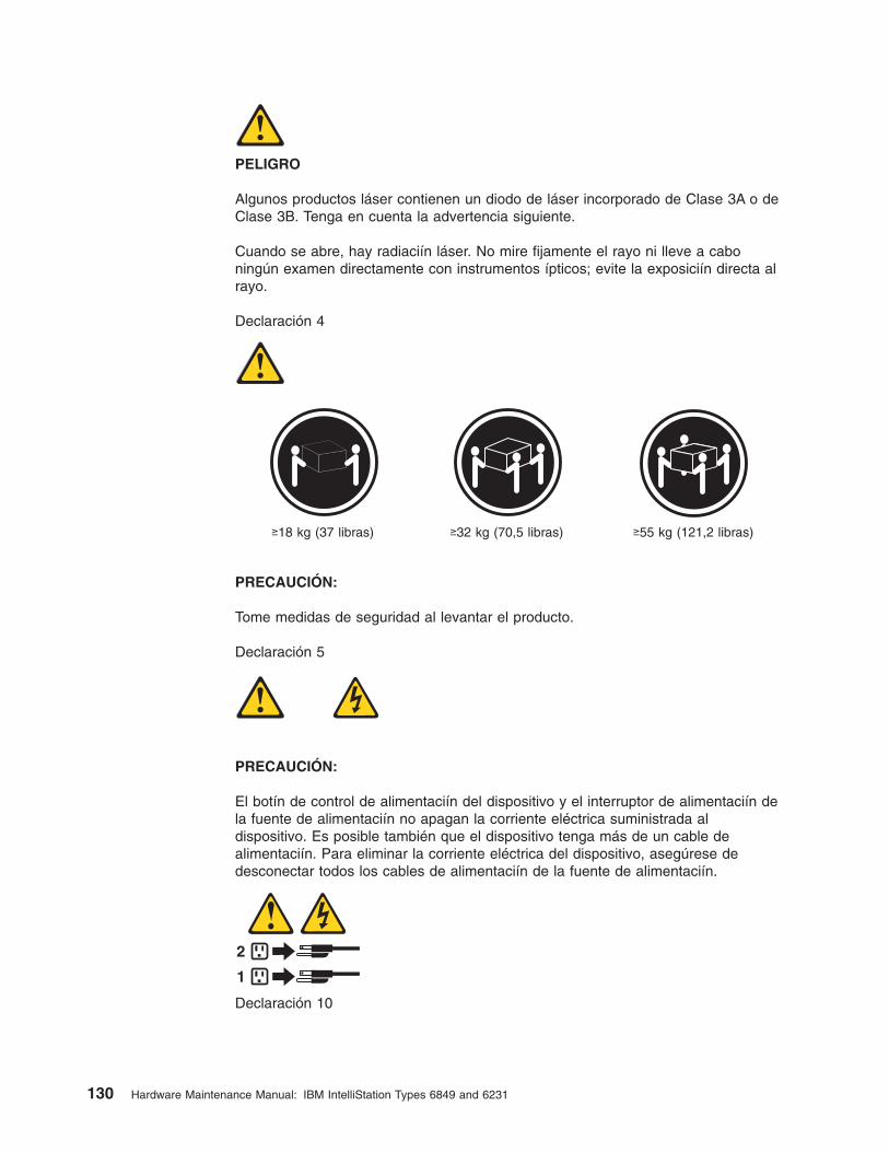
PELIGRO
Algunos productos láser contienen un diodo de láser incorporado de Clase 3A o de
Clase 3B. Tenga en cuenta la advertencia siguiente.
Cuando se abre, hay radiaciín láser. No mire fijamente el rayo ni lleve a cabo
ningún examen directamente con instrumentos ípticos; evite la exposiciín directa al
rayo.
Declaración 4
≥18 kg (37 libras) ≥32 kg (70,5 libras) ≥55 kg (121,2 libras)
PRECAUCIÓN:
Tome medidas de seguridad al levantar el producto.
Declaración 5
PRECAUCIÓN:
El botín de control de alimentaciín del dispositivo y el interruptor de alimentaciín de
la fuente de alimentaciín no apagan la corriente eléctrica suministrada al
dispositivo. Es posible también que el dispositivo tenga más de un cable de
alimentaciín. Para eliminar la corriente eléctrica del dispositivo, asegúrese de
desconectar todos los cables de alimentaciín de la fuente de alimentaciín.
1
2
Declaración 10
130 Hardware Maintenance Manual: IBM IntelliStation Types 6849 and 6231
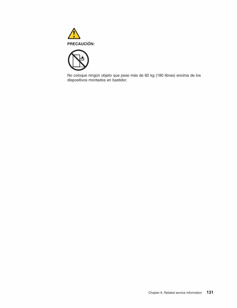
PRECAUCIÓN:
No coloque ningún objeto que pese más de 82 kg (180 libras) encima de los
dispositivos montados en bastidor.
Chapter 9. Related service information 131

Send us your comments!
We want to know your opinion about this manual (part number 22p3034). Your input
will help us to improve our publications.
Please photocopy this survey, complete it, and then fax it to IBM HMM Survey at
919-543-8167 (USA).
Name: _________________________________________
Phone number: __________________________________
1. Do you like this manual?
h Yes h No
_________________________________________
_________________________________________
2. What would you like to see added, changed, or deleted in this manual?
_________________________________________
_________________________________________
3. What is your service experience level?
h Less than five years
h More than five years
4. Which Servers do you service most?
_________________________________________
_________________________________________
_________________________________________
_________________________________________
Thank you for your response!
132 Hardware Maintenance Manual: IBM IntelliStation Types 6849 and 6231

Problem determination tips
Due to the variety of hardware and software combinations that can be encountered,
use the following information to assist you in problem determination. If possible,
have this information available when requesting assistance from Service Support
and Engineering functions.
v Machine type and model
v Processor or hard disk upgrades
v Failure symptom
– Do diagnostics fail?
– What, when, where, single, or multiple systems?
– Is the failure repeatable?
– Has this configuration ever worked?
– If it has been working, what changes were made prior to it failing?
– Is this the original reported failure?
v Reference/Diagnostics version
– Type and version level
v Hardware configuration
– Print (print screen) configuration currently in use
– BIOS level
v Operating system software
– Type and version level
Note: To eliminate confusion, identical systems are considered identical only if
they:
1. Are the exact machine type and models
2. Have the same BIOS level
3. Have the same adapters/attachments in the same locations
4. Have the same address jumpers/terminators/cabling
5. Have the same software versions and levels
6. Have the same Reference/Diagnostics Diskette (version)
7. Have the same configuration options set in the system
8. Have the same setup for the operation system control files
Comparing the configuration and software set-up between ″working and
non-working″ systems will often lead to problem resolution.
Notices
References in this publication to IBM products, programs, or services do not imply
that IBM intends to make these available in all countries in which IBM operates. Any
reference to an IBM product, program, or service is not intended to state or imply
that only that IBM product, program, or service may be used. Subject to IBM’s valid
intellectual property or other legally protectable rights, any functionally equivalent
product, program, or service may be used instead of the IBM product, program, or
service. The evaluation and verification of operation in conjunction with other
products, except those expressly designated by IBM, are the responsibility of the
user.
Chapter 9. Related service information 133

Trademarks
The following items are trademarks of the IBM Corporation in the United States or
other countries or both:
Alert on LAN Etherjet
Ethernet HelpCenter
HelpWare IBM
IntelliStation RETAIN
ScrollPoint ValuePoint
Wake on LAN
The following terms are trademarks of other companies:
Notes Lotus Development Corporation
Lotus and Domino are trademarks of Lotus Development Corporation in the United
States, other countries, or both.
Tivoli and NetView are trademarks of Tivoli Systems Inc. in the United States, other
countries, or both.
Intel, MMX, LANDesk, Pentium, Pentium II Xeon, and Pentium III Xeon, and
Pentium 4 are trademarks or registered trademarks of Intel Corporation in the
United States, other countries, or both.
Microsoft, Windows, and Windows NT are trademarks or registered trademarks of
Microsoft Corporation.
Other company, product, and service names may be trademarks or service marks
of others.
134 Hardware Maintenance Manual: IBM IntelliStation Types 6849 and 6231


����
Part Number: 22P3034
Printed in USA
(1P) P/N: 22P3034