redpaper 04, 2003 · draft document for review september 4, 2003 7:41 pm redp-3690-00...
TRANSCRIPT
Draft Document for Review September 4, 2003 7:41 pm REDP-3690-00
ibm.com/redbooks Redpaper
Front cover
IBM TotalStorage: FAStT Best Practices Guide
Bertrand DufrasneBernd Baeuml
Carlos De NobregaAles Leskosek
Stephen ManthorpeJonathan Wright
FAStT Concepts and Planning
Implementation and Tuning Tips
Advanced Topics


International Technical Support Organization
IBM TotalStorage: FAStT Best Practices Guide
September 2003
Draft Document for Review September 4, 2003 7:41 pm 3690edno.fm

3690edno.fm Draft Document for Review September 4, 2003 7:41 pm
First Edition (September 2003)
This document created or updated on September 4, 2003.
Note: Before using this information and the product it supports, read the information in “Notices” on page vii.
© Copyright International Business Machines Corporation 2003. All rights reserved.Note to U.S. Government Users Restricted Rights -- Use, duplication or disclosure restricted by GSA ADP ScheduleContract with IBM Corp.

Draft Document for Review September 4, 2003 7:41 pm 3690edno.fm
iii

3690edno.fm Draft Document for Review September 4, 2003 7:41 pm
iv IBM TotalStorage: FAStT Best Practices Guide

Draft Document for Review September 4, 2003 7:41 pm 3690TOC.fm
Contents
Notices . . . . . . . . . . . . . . . . . . . . . . . . . . . . . . . . . . . . . . . . . . . . . . . . . . . . . . . . . . . . . . . . . viiTrademarks . . . . . . . . . . . . . . . . . . . . . . . . . . . . . . . . . . . . . . . . . . . . . . . . . . . . . . . . . . . . . viii
Preface . . . . . . . . . . . . . . . . . . . . . . . . . . . . . . . . . . . . . . . . . . . . . . . . . . . . . . . . . . . . . . . . . ixThe team that wrote this Redpaper . . . . . . . . . . . . . . . . . . . . . . . . . . . . . . . . . . . . . . . . . . . . ixBecome a published author . . . . . . . . . . . . . . . . . . . . . . . . . . . . . . . . . . . . . . . . . . . . . . . . . . xiComments welcome. . . . . . . . . . . . . . . . . . . . . . . . . . . . . . . . . . . . . . . . . . . . . . . . . . . . . . . . xi
Chapter 1. Introduction to FAStT . . . . . . . . . . . . . . . . . . . . . . . . . . . . . . . . . . . . . . . . . . . . 11.1 FAStT models . . . . . . . . . . . . . . . . . . . . . . . . . . . . . . . . . . . . . . . . . . . . . . . . . . . . . . . . . 21.2 Storage Manager . . . . . . . . . . . . . . . . . . . . . . . . . . . . . . . . . . . . . . . . . . . . . . . . . . . . . . 4
1.2.1 FAStT Storage Manager components. . . . . . . . . . . . . . . . . . . . . . . . . . . . . . . . . . . 41.2.2 New Features of Storage Manager version 8.4 . . . . . . . . . . . . . . . . . . . . . . . . . . . 5
Chapter 2. FAStT and Storage Area Network . . . . . . . . . . . . . . . . . . . . . . . . . . . . . . . . . . 92.1 Introduction to SAN . . . . . . . . . . . . . . . . . . . . . . . . . . . . . . . . . . . . . . . . . . . . . . . . . . . . 10
2.1.1 SAN components . . . . . . . . . . . . . . . . . . . . . . . . . . . . . . . . . . . . . . . . . . . . . . . . . 102.1.2 Planning your SAN . . . . . . . . . . . . . . . . . . . . . . . . . . . . . . . . . . . . . . . . . . . . . . . . 12
2.2 Zoning . . . . . . . . . . . . . . . . . . . . . . . . . . . . . . . . . . . . . . . . . . . . . . . . . . . . . . . . . . . . . . 142.2.1 Zone types . . . . . . . . . . . . . . . . . . . . . . . . . . . . . . . . . . . . . . . . . . . . . . . . . . . . . . 15
2.3 FAStT physical installation considerations . . . . . . . . . . . . . . . . . . . . . . . . . . . . . . . . . . 162.3.1 Rack considerations . . . . . . . . . . . . . . . . . . . . . . . . . . . . . . . . . . . . . . . . . . . . . . . 162.3.2 Cable management and labeling . . . . . . . . . . . . . . . . . . . . . . . . . . . . . . . . . . . . . 18
2.4 FAStT Cabling . . . . . . . . . . . . . . . . . . . . . . . . . . . . . . . . . . . . . . . . . . . . . . . . . . . . . . . . 202.4.1 FAStT600 Cabling Configuration . . . . . . . . . . . . . . . . . . . . . . . . . . . . . . . . . . . . . 202.4.2 FAStT900 Cabling Configuration . . . . . . . . . . . . . . . . . . . . . . . . . . . . . . . . . . . . . 23
2.5 Hot-scaling the IBM TotalStorage FAStT Series. . . . . . . . . . . . . . . . . . . . . . . . . . . . . . 262.5.1 Adding capacity. . . . . . . . . . . . . . . . . . . . . . . . . . . . . . . . . . . . . . . . . . . . . . . . . . . 262.5.2 Increasing bandwidth . . . . . . . . . . . . . . . . . . . . . . . . . . . . . . . . . . . . . . . . . . . . . . 27
Chapter 3. FAStT Planning Tasks . . . . . . . . . . . . . . . . . . . . . . . . . . . . . . . . . . . . . . . . . . 293.1 General considerations . . . . . . . . . . . . . . . . . . . . . . . . . . . . . . . . . . . . . . . . . . . . . . . . . 303.2 Physical components and characteristics . . . . . . . . . . . . . . . . . . . . . . . . . . . . . . . . . . . 31
3.2.1 Cabling . . . . . . . . . . . . . . . . . . . . . . . . . . . . . . . . . . . . . . . . . . . . . . . . . . . . . . . . . 313.2.2 Fibre Channel adapters . . . . . . . . . . . . . . . . . . . . . . . . . . . . . . . . . . . . . . . . . . . . 323.2.3 Planing your Storage Structure and Performance . . . . . . . . . . . . . . . . . . . . . . . . 343.2.4 Logical drives and controller ownership . . . . . . . . . . . . . . . . . . . . . . . . . . . . . . . . 393.2.5 Segment Size . . . . . . . . . . . . . . . . . . . . . . . . . . . . . . . . . . . . . . . . . . . . . . . . . . . . 423.2.6 Storage Partitioning . . . . . . . . . . . . . . . . . . . . . . . . . . . . . . . . . . . . . . . . . . . . . . . 423.2.7 Cache parameters . . . . . . . . . . . . . . . . . . . . . . . . . . . . . . . . . . . . . . . . . . . . . . . . 433.2.8 Hot-spare drive . . . . . . . . . . . . . . . . . . . . . . . . . . . . . . . . . . . . . . . . . . . . . . . . . . . 473.2.9 Remote Volume Mirroring . . . . . . . . . . . . . . . . . . . . . . . . . . . . . . . . . . . . . . . . . . . 48
3.3 Logical layer . . . . . . . . . . . . . . . . . . . . . . . . . . . . . . . . . . . . . . . . . . . . . . . . . . . . . . . . . 503.3.1 Planning for systems with LVM - AIX example . . . . . . . . . . . . . . . . . . . . . . . . . . . 503.3.2 Planning for systems without LVM - Windows example . . . . . . . . . . . . . . . . . . . . 52
3.4 Other considerations for multi-pathing and redundancy . . . . . . . . . . . . . . . . . . . . . . . . 543.4.1 The Function of ADT and a multipath driver . . . . . . . . . . . . . . . . . . . . . . . . . . . . . 543.4.2 ADT alert notification. . . . . . . . . . . . . . . . . . . . . . . . . . . . . . . . . . . . . . . . . . . . . . . 56
© Copyright IBM Corp. 2003. All rights reserved. v

3690TOC.fm Draft Document for Review September 4, 2003 7:41 pm
Chapter 4. FAStT Implementation Tasks . . . . . . . . . . . . . . . . . . . . . . . . . . . . . . . . . . . . . 614.1 Preparing the FAStT Storage Server . . . . . . . . . . . . . . . . . . . . . . . . . . . . . . . . . . . . . . 62
4.1.1 Network setup of the controllers . . . . . . . . . . . . . . . . . . . . . . . . . . . . . . . . . . . . . . 624.1.2 Installing and Starting the FAStT Storage Manager Client . . . . . . . . . . . . . . . . . . 634.1.3 Updating the controller microcode . . . . . . . . . . . . . . . . . . . . . . . . . . . . . . . . . . . . 65
4.2 Configuring the IBM TotalStorage FAStT Storage Server . . . . . . . . . . . . . . . . . . . . . . 664.2.1 Defining hot-spare drives . . . . . . . . . . . . . . . . . . . . . . . . . . . . . . . . . . . . . . . . . . . 664.2.2 Creating arrays and logical drives. . . . . . . . . . . . . . . . . . . . . . . . . . . . . . . . . . . . . 674.2.3 Configuring storage partitioning . . . . . . . . . . . . . . . . . . . . . . . . . . . . . . . . . . . . . . 68
Chapter 5. FAStT Maintenance. . . . . . . . . . . . . . . . . . . . . . . . . . . . . . . . . . . . . . . . . . . . . 715.1 Performance monitoring and tuning . . . . . . . . . . . . . . . . . . . . . . . . . . . . . . . . . . . . . . . 72
5.1.1 The performance monitor . . . . . . . . . . . . . . . . . . . . . . . . . . . . . . . . . . . . . . . . . . . 725.1.2 Tuning cache parameters . . . . . . . . . . . . . . . . . . . . . . . . . . . . . . . . . . . . . . . . . . . 74
5.2 Controlling the performance impact of maintenance tasks . . . . . . . . . . . . . . . . . . . . . . 745.2.1 Modification operations . . . . . . . . . . . . . . . . . . . . . . . . . . . . . . . . . . . . . . . . . . . . . 745.2.2 Remote Volume Mirroring Operations. . . . . . . . . . . . . . . . . . . . . . . . . . . . . . . . . . 765.2.3 VolumeCopy priority rates. . . . . . . . . . . . . . . . . . . . . . . . . . . . . . . . . . . . . . . . . . . 765.2.4 FlashCopy operations . . . . . . . . . . . . . . . . . . . . . . . . . . . . . . . . . . . . . . . . . . . . . . 76
5.3 Event monitoring and alerts . . . . . . . . . . . . . . . . . . . . . . . . . . . . . . . . . . . . . . . . . . . . . 775.3.1 IBM FASt Service Alert . . . . . . . . . . . . . . . . . . . . . . . . . . . . . . . . . . . . . . . . . . . . . 77
5.4 Saving the subsystem profile . . . . . . . . . . . . . . . . . . . . . . . . . . . . . . . . . . . . . . . . . . . . 825.5 Upgrades and Maintenance . . . . . . . . . . . . . . . . . . . . . . . . . . . . . . . . . . . . . . . . . . . . . 82
5.5.1 Prerequisites for upgrades . . . . . . . . . . . . . . . . . . . . . . . . . . . . . . . . . . . . . . . . . . 825.5.2 Updating FAStT host software . . . . . . . . . . . . . . . . . . . . . . . . . . . . . . . . . . . . . . . 835.5.3 Updating microcode . . . . . . . . . . . . . . . . . . . . . . . . . . . . . . . . . . . . . . . . . . . . . . . 83
Chapter 6. FAStT and HACMP . . . . . . . . . . . . . . . . . . . . . . . . . . . . . . . . . . . . . . . . . . . . . 856.1 HACMP introduction . . . . . . . . . . . . . . . . . . . . . . . . . . . . . . . . . . . . . . . . . . . . . . . . . . . 866.2 Supported environment . . . . . . . . . . . . . . . . . . . . . . . . . . . . . . . . . . . . . . . . . . . . . . . . . 87
6.2.1 General rules . . . . . . . . . . . . . . . . . . . . . . . . . . . . . . . . . . . . . . . . . . . . . . . . . . . . 886.2.2 Configuration limitations . . . . . . . . . . . . . . . . . . . . . . . . . . . . . . . . . . . . . . . . . . . . 89
Chapter 7. FAStT and GPFS for AIX . . . . . . . . . . . . . . . . . . . . . . . . . . . . . . . . . . . . . . . . 917.1 GPFS Introduction. . . . . . . . . . . . . . . . . . . . . . . . . . . . . . . . . . . . . . . . . . . . . . . . . . . . . 927.2 Supported Configurations . . . . . . . . . . . . . . . . . . . . . . . . . . . . . . . . . . . . . . . . . . . . . . . 93
Related publications . . . . . . . . . . . . . . . . . . . . . . . . . . . . . . . . . . . . . . . . . . . . . . . . . . . . . 99IBM Redbooks . . . . . . . . . . . . . . . . . . . . . . . . . . . . . . . . . . . . . . . . . . . . . . . . . . . . . . . . . . . 99Online resources . . . . . . . . . . . . . . . . . . . . . . . . . . . . . . . . . . . . . . . . . . . . . . . . . . . . . . . . . 99How to get IBM Redbooks . . . . . . . . . . . . . . . . . . . . . . . . . . . . . . . . . . . . . . . . . . . . . . . . . . 99Help from IBM . . . . . . . . . . . . . . . . . . . . . . . . . . . . . . . . . . . . . . . . . . . . . . . . . . . . . . . . . . . 99
Index . . . . . . . . . . . . . . . . . . . . . . . . . . . . . . . . . . . . . . . . . . . . . . . . . . . . . . . . . . . . . . . . . 101
vi IBM TotalStorage: FAStT Best Practices Guide

Draft Document for Review September 4, 2003 7:41 pm 3690spec.fm
Notices
This information was developed for products and services offered in the U.S.A.
IBM may not offer the products, services, or features discussed in this document in other countries. Consult your local IBM representative for information on the products and services currently available in your area. Any reference to an IBM product, program, or service is not intended to state or imply that only that IBM product, program, or service may be used. Any functionally equivalent product, program, or service that does not infringe any IBM intellectual property right may be used instead. However, it is the user's responsibility to evaluate and verify the operation of any non-IBM product, program, or service.
IBM may have patents or pending patent applications covering subject matter described in this document. The furnishing of this document does not give you any license to these patents. You can send license inquiries, in writing, to: IBM Director of Licensing, IBM Corporation, North Castle Drive Armonk, NY 10504-1785 U.S.A.
The following paragraph does not apply to the United Kingdom or any other country where such provisions are inconsistent with local law: INTERNATIONAL BUSINESS MACHINES CORPORATION PROVIDES THIS PUBLICATION "AS IS" WITHOUT WARRANTY OF ANY KIND, EITHER EXPRESS OR IMPLIED, INCLUDING, BUT NOT LIMITED TO, THE IMPLIED WARRANTIES OF NON-INFRINGEMENT, MERCHANTABILITY OR FITNESS FOR A PARTICULAR PURPOSE. Some states do not allow disclaimer of express or implied warranties in certain transactions, therefore, this statement may not apply to you.
This information could include technical inaccuracies or typographical errors. Changes are periodically made to the information herein; these changes will be incorporated in new editions of the publication. IBM may make improvements and/or changes in the product(s) and/or the program(s) described in this publication at any time without notice.
Any references in this information to non-IBM Web sites are provided for convenience only and do not in any manner serve as an endorsement of those Web sites. The materials at those Web sites are not part of the materials for this IBM product and use of those Web sites is at your own risk.
IBM may use or distribute any of the information you supply in any way it believes appropriate without incurring any obligation to you.
Information concerning non-IBM products was obtained from the suppliers of those products, their published announcements or other publicly available sources. IBM has not tested those products and cannot confirm the accuracy of performance, compatibility or any other claims related to non-IBM products. Questions on the capabilities of non-IBM products should be addressed to the suppliers of those products.
This information contains examples of data and reports used in daily business operations. To illustrate them as completely as possible, the examples include the names of individuals, companies, brands, and products. All of these names are fictitious and any similarity to the names and addresses used by an actual business enterprise is entirely coincidental.
COPYRIGHT LICENSE: This information contains sample application programs in source language, which illustrates programming techniques on various operating platforms. You may copy, modify, and distribute these sample programs in any form without payment to IBM, for the purposes of developing, using, marketing or distributing application programs conforming to the application programming interface for the operating platform for which the sample programs are written. These examples have not been thoroughly tested under all conditions. IBM, therefore, cannot guarantee or imply reliability, serviceability, or function of these programs. You may copy, modify, and distribute these sample programs in any form without payment to IBM for the purposes of developing, using, marketing, or distributing application programs conforming to IBM's application programming interfaces.
© Copyright IBM Corp. 2003. All rights reserved. vii
3690spec.fm Draft Document for Review September 4, 2003 7:41 pm
TrademarksThe following terms are trademarks of the International Business Machines Corporation in the United States, other countries, or both:
AIX 5L™AIX®DFS™FICON™FlashCopy®ibm.com®IBM®
Netfinity®Notes®Perform™pSeries™Redbooks(logo) ™Redbooks™RS/6000®
S/390®Sequent®TotalStorage®
™xSeries®z/OS®
The following terms are trademarks of other companies:
Intel, Intel Inside (logos), MMX, and Pentium are trademarks of Intel Corporation in the United States, other countries, or both.
Microsoft, Windows, Windows NT, and the Windows logo are trademarks of Microsoft Corporation in the United States, other countries, or both.
Java and all Java-based trademarks and logos are trademarks or registered trademarks of Sun Microsystems, Inc. in the United States, other countries, or both.
UNIX is a registered trademark of The Open Group in the United States and other countries.
SET, SET Secure Electronic Transaction, and the SET Logo are trademarks owned by SET Secure Electronic Transaction LLC.
Other company, product, and service names may be trademarks or service marks of others.
viii IBM TotalStorage: FAStT Best Practices Guide
Draft Document for Review September 4, 2003 7:41 pm 3690pref.fm
Preface
This Redpaper is a best practices document for FAStT. It is aimed at giving the basics on how to configure your installation. It is a compilation of recommendations for planning, designing, implementing and maintainig FAStT storage solutions.
Setting up a FAStT Storage Server can be a complex task. There is no single configuration that will be satisfactory for every application or situation. This Redpaper provides a starting point on how to configure your installation to make it reliable, performant and easier to manage.
The Redpaper provides the conceptual framework for understanding FAStT in a Storage Area Network and includes recommendations, hints and tips for the physical installation, cabling and zoning. Although no performance figures are included, the document discusses performance and tuning of various components and features to guide you when working with FAStT.
The last two chapters of the book present and discuss HACMP and GPFS as they relate to FAStT.
The team that wrote this RedpaperThis Redpaper was produced by a team of specialists from around the world working at the International Technical Support Organization, San Jose Center.
Bertrand Dufrasne is a Certified Consulting I/T Specialist and Project Leader for Disk Storage Systems at the International Technical Support Organization, San Jose Center. He has worked at IBM for 21 years in many I/T areas. Before joining the ITSO he worked for IBM Global Services in the US as an I/T Architect. He holds a degree in Electrical Engineering.
Bernd Baeuml is a Senior Technical Support Specialist for IBM Storage Division Back Office based in Greenock, Scotland. He has seven years of experience with IBM hardware and software. His areas of expertise include FAStT Storage Server, Windows and Unix based operating systems. He is a co-author of two redbooks about Netfinitiy server management. He holds a Masters of Engineering degree from the Hochschule fuer Technik and Wirtschaft Dresden. He is PSE and CNE.
Carlos De Nobrega is a xSeries and FAStT Product Manager working in Field Support Group in IBM Global Services in South Africa ,performing level 2 support and product management for xSeries and FAStT Storage Products . He has 5 years of experience in the High Volume Intel platform / storage field. He has worked at IBM for 8 years. He is qualified as an Electrical Engineer and his main focus of interest and expertise is in the Intel Server market and FAStT / Storage Area Networks .
Ales Leskosek is an I/T Specialist with IBM Slovenia and has nearly 4 years of experience as Field Technical Support Specialist for the CEMA region. His activities include pre-sales and post-sales support, from designing end-to-end storage solutions and competitive positioning to implementation and problem determination across the entire range of IBM TotalStorage products. Ales has taught storage classes and has spoken as a subject matter expert at industry events.
© Copyright IBM Corp. 2003. All rights reserved. ix

3690pref.fm Draft Document for Review September 4, 2003 7:41 pm
Stephen Manthorpe is a country Enterprise Systems Disk Specialist, based in Canberra, Australia. He joined IBM in 1988 and has 15 years of experience in S/390 systems, storage products and laser printing systems. He has for 3 years provided technical support for ESS and SAN to Australia, New Zealand and the ASEAN region.
Jonathan Wright is a technical specialist in New Zealand. He has 10 years of experience in the Intel server and storage field. His areas of expertise include xSeries hardware, Linux, clustering and FAStT Storage
Thanks to the following people for their contributions to this project:
Barry MellishInternational Technical Support Organization, San Jose Center
Travis WilliamsIBM Dallas - HACMP Storage
Gordon McPheetersIBM Poughkeepsie - GPFS Test Team
Jay SmithGeorge ThomasShawn BramblettIBM SSG Tucson
Dolores ButcherIBM Tucson
Bruce AllworthGene CullumJames GoodwinTodd VirnocheDan BradenIBM Advanced Technical Support, Americas
Michael QuillenIBM Beaverton
Arwed TschoekeIBM Germany
Mic WatkinsIBM Raleigh
Chuck GrimmIBM Technical Support Marketing Lead
Harold PikeIBM Raleigh -
John MurtaghIBM SSG FAStT Product Manager
Tai ChangIBM San Jose FAStT Program Manager
x TotalStorage: FAStT Best Practices Guide
Draft Document for Review September 4, 2003 7:41 pm 3690pref.fm
Dave WorleyJohn BishLSI Logic
Become a published authorJoin us for a two- to six-week residency program! Help write an IBM Redbook dealing with specific products or solutions, while getting hands-on experience with leading-edge technologies. You'll team with IBM technical professionals, Business Partners and/or customers.
Your efforts will help increase product acceptance and customer satisfaction. As a bonus, you'll develop a network of contacts in IBM development labs, and increase your productivity and marketability.
Find out more about the residency program, browse the residency index, and apply online at:
ibm.com/redbooks/residencies.html
Comments welcomeYour comments are important to us!
We want our papers to be as helpful as possible. Send us your comments about this Redpaper or other Redbooks in one of the following ways:
� Use the online Contact us review redbook form found at:
ibm.com/redbooks
� Send your comments in an Internet note to:
� Mail your comments to:
IBM Corporation, International Technical Support OrganizationDept. QXXE Building 80-E2650 Harry RoadSan Jose, California 95120-6099
Preface xi

3690pref.fm Draft Document for Review September 4, 2003 7:41 pm
xii TotalStorage: FAStT Best Practices Guide
Draft Document for Review September 4, 2003 7:41 pm 3690Intro.fm
Chapter 1. Introduction to FAStT
This chapter introduces the IBM TotalStorage FAStT Storage Server products with a brief description of the different models, their features and where they fit in terms of storage solution.
The remaining of this chapter summarizes the functions of the FAStT Storage Manager software, and emphasizes features of Storage Manager 8.4 including the new VolumeCopy premium feature.
1
© Copyright IBM Corp. 2003. All rights reserved. 1

3690Intro.fm Draft Document for Review September 4, 2003 7:41 pm
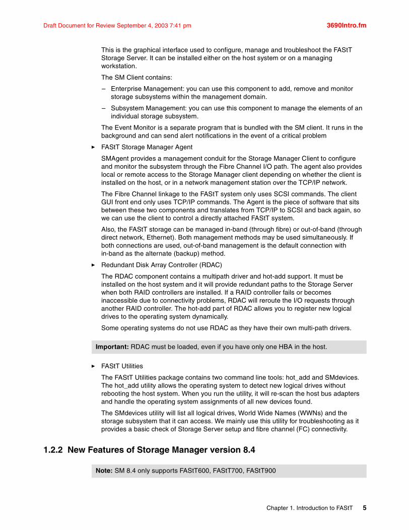
1.1 FAStT modelsThe IBM TotalStorage FAStT Storage Server is a RAID storage subsystem that contains the Fibre Channel (FC) interfaces to connect both the host systems and the disk drive enclosures. The Storage Server provides high system availability through the use of hot-swappable and redundant components. This is crucial as the Storage Server is placed in high end customer environments such as server consolidation on Storage Area Networks (SAN).
Figure 1-1, shows the characteristics and the evolution of the IBM TotalStorage FAStT series.
Figure 1-1 The IBM TotalSTorage FAStT series
� FAStT200 Storage Server
The FAStT200 is designed for workgroup and departmental servers that require an external storage solution. The single controller model provides a cost-effective solution, while the FAStT200 High Availability (HA) model features a fully redundant configuration with dual-active controllers. As your storage requirements grow, you can easily expand storage capacity by adding IBM FAStT EXP500 (50 drives) or EXP700 (56 drives). Expansion units scale from 18Gb to 1.47TB in a compact 3U size with a maximum system capacity of 9.6TB. FlashCopy is supported and provides fast data duplication capability, reducing or eliminating the need for long shutdowns during backups and restores.
� FAStT600 and FAStT600 Turbo Storage Servers
The FAStT600 and FAStT600 Turbo are among the latest additions to the FAStT family of products.
The FAStT600 is an entry level, highly scalable 2Gb Fibre Channel Storage Server.
Performance, Availability, Scalability, Redundancy
3U, Single or Dual 1Gb ControllersRAID Cache - 128MB single controller
- 256MB dual controllerMax Drives- 60 SL/HH2 Host FC ports
Dual 2Gb ControllersRAID Cache- 512MBMax Drives- 56 4 Host FC Ports
FAStT 600
FAStT 200
Dual 2Gb ControllersRAID Cache - 2GB Max Drives - 112 4 Host FC PortsCopy Services Options30-100%+ Performance boost over the base FAStT600
*FAStT 600w/ Turbo Option
Dual 2Gb ControllersRAID Cache - 2GBMax Drives- 224 4 Host Mini Hubs Copy Services Options
FAStT 700
Dual 2Gb ControllersRAID Cache - 2GB Max drives - 224 4 Host Mini HubsCopy Services OptionsHighest Performance
FAStT 900
2 TotalStorage: FAStT Best Practices Guide
Draft Document for Review September 4, 2003 7:41 pm 3690Intro.fm
It is designed to a be cost -effective, scalable storage server for consolidation and clustering applications. Its modular architecture can support on demand business models by enabling an entry configuration that can easily grow as storage demands increase (up to 8.2TB of capacity). Supporting up to 56 drives (using three EXP700 Expansion units), it is designed to deliver high performance of up to 400MB/sec. Dynamic capacity addition provides the ability to add an EXP700 enclosure to an existing FAStT600 without stopping operations. The FAStT600 can provide capacity on demand, allowing unused storage to be brought online for a new host group or an existing volume.
The FAStT600 Turbo is a mid-level storage server that can scale to over sixteen terabytes, facilitating storage consolidation for medium-sized customers. It uses the latest in storage networking technology to provide an end-to-end 2 Gbps Fibre Channel solution ( the host interface on base FAStT600 is 2Gb, while Turbo auto senses to connect to 1Gb or 2Gb) and offers up to 70% performance improvement (with new Storage Manager v8.4 that ships with Turbo). It has higher scalability over the base FAStT600, up to 16.4TB for a total of 112 disks - using a maximum of 7 EXP700s. The FAStT600 Turbo supports up to 64 storage partitions. The cache has increased from 256MB per controler on base FAStT600 to 1GB per controller on Turbo ; finally it offfers autonomic functions such as Dynamic Volume Expansion and Dynamic Capacity Addition, allowing unused storage to be brought on-line without stopping operations, and FAStT Service Alert, which is capable of automatically alerting IBM if a problem occurs.
� FAStT500 Storage Server
This Storage Server can support medium to high-end configurations with greater storage capability as well as supporting heterogeneous host systems.Offers a higher level of availability, performance and expandability than the FAStT200. The TotalStorage FAStT500 solution is designed to provide security against component failures. Dual Hot swap RAID controllers helps provide throughput and redundancy, and each controller supports up to 512MB of batter backed cache. Redundant fans, power supplies and dynamic storage management further contribute to availability. Capacity scalable from 18Gb to greater than 32TB supporting up 224 drives using either 22 EXP500 or 16 EXP700.
� FAStT700 Storage Server
Offers 2Gbps technology for faster response time. Scales from 36GB to greater than 32TB of storage using 16 EXP700 expansion enclosures. Each expansion enclosure supports up to fourteen 2Gbps Fibre channel disk drives. Moreover, you can select the appropriate RAID level (from RAID 0,1,3,5 and 10) to match an application or suit particular needs. The FAStT700 also supports all premium features such as FlashCopy, VolumeCopy, Remote Volume Mirroring and Storage Partitioning.
This storage server supports high-end configurations with up to 64 heterogeneous host systems. High availability is critical in today’s knowledge-based economy: the TotalStorage FASTT700 Storage Server is designed to support high availability, providing protection against component failures. Dual hot swap RAID controllers help provide high throughput and redundancy; each controller supports 1Gb of battery backed cache. Redundant fans, power supplies and dynamic storage management further support high availability and help reduce the risk of costly downtime or the loss of valuable data.
� FAStT900 Storage Server
IBM FAStT900 Storage Server delivers breakthrough disk performance and outstanding reliability for demanding applications in compute intensive environments. The FAStT900 is designed to offer investment protection with advanced functions and flexible features. Designed for today’s on-demand business needs, the FAStT900 easily scales from 36GB
Note: the FAStT500 has been withdrawn from marketing.
Chapter 1. Introduction to FAStT 3
3690Intro.fm Draft Document for Review September 4, 2003 7:41 pm
to over 32TB to support growing storage requirements. The FAStT900 offers advanced replication services to support business continuance and disaster recovery. The FAStT900 is an effective storage server for any enterprise seeking performance without borders.
The FAStT900 uses 2Gb Fibre Channel connectivity to support high performance (772 MB/sec throughput from disk) for faster, more responsive access to data. It provides flexibility for multiplatform storage environments by supporting a wide variety of servers, operating systems and cluster technologies (certified for Microsoft Cluster Server, Novell clustering, HACMP, Veritas Cluster for Solaris). This storage server is well suited for high performance applications such as online transaction processing (OLTP), data mining and digital media.
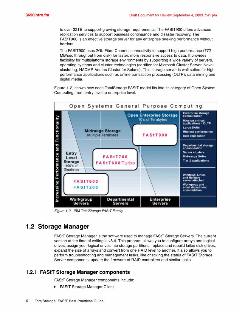
Figure 1-2, shows how each TotalStorage FAStT model fits into its category of Open System Computing, from entry level to enterprise level.
Figure 1-2 IBM TotalStorage FAStT Family
1.2 Storage ManagerFAStT Storage Manager is the software used to manage FAStT Storage Servers. The current version at the time of writing is v8.4. This program allows you to configure arrays and logical drives, assign your logical drives into storage partitions, replace and rebuild failed disk drives, expand the size of arrays and convert from one RAID level to another. It also allows you to perform troubleshooting and management tasks, like checking the status of FAStT Storage Server components, update the firmware of RAID controllers and similar tasks.
1.2.1 FAStT Storage Manager componentsFAStT Storage Manager components include:
� FAStT Storage Manager Client
4 TotalStorage: FAStT Best Practices Guide
Draft Document for Review September 4, 2003 7:41 pm 3690Intro.fm
This is the graphical interface used to configure, manage and troubleshoot the FAStT Storage Server. It can be installed either on the host system or on a managing workstation.
The SM Client contains:
– Enterprise Management: you can use this component to add, remove and monitor storage subsystems within the management domain.
– Subsystem Management: you can use this component to manage the elements of an individual storage subsystem.
The Event Monitor is a separate program that is bundled with the SM client. It runs in the background and can send alert notifications in the event of a critical problem
� FAStT Storage Manager Agent
SMAgent provides a management conduit for the Storage Manager Client to configure and monitor the subsystem through the Fibre Channel I/O path. The agent also provides local or remote access to the Storage Manager client depending on whether the client is installed on the host, or in a network management station over the TCP/IP network.
The Fibre Channel linkage to the FAStT system only uses SCSI commands. The client GUI front end only uses TCP/IP commands. The Agent is the piece of software that sits between these two components and translates from TCP/IP to SCSI and back again, so we can use the client to control a directly attached FAStT system.
Also, the FAStT storage can be managed in-band (through fibre) or out-of-band (through direct network, Ethernet). Both management methods may be used simultaneously. If both connections are used, out-of-band management is the default connection with in-band as the alternate (backup) method.
� Redundant Disk Array Controller (RDAC)
The RDAC component contains a multipath driver and hot-add support. It must be installed on the host system and it will provide redundant paths to the Storage Server when both RAID controllers are installed. If a RAID controller fails or becomes inaccessible due to connectivity problems, RDAC will reroute the I/O requests through another RAID controller. The hot-add part of RDAC allows you to register new logical drives to the operating system dynamically.
Some operating systems do not use RDAC as they have their own multi-path drivers.
� FAStT Utilities
The FAStT Utilities package contains two command line tools: hot_add and SMdevices. The hot_add utility allows the operating system to detect new logical drives without rebooting the host system. When you run the utility, it will re-scan the host bus adapters and handle the operating system assignments of all new devices found.
The SMdevices utility will list all logical drives, World Wide Names (WWNs) and the storage subsystem that it can access. We mainly use this utility for troubleshooting as it provides a basic check of Storage Server setup and fibre channel (FC) connectivity.
1.2.2 New Features of Storage Manager version 8.4
Important: RDAC must be loaded, even if you have only one HBA in the host.
Note: SM 8.4 only supports FAStT600, FAStT700, FAStT900
Chapter 1. Introduction to FAStT 5
3690Intro.fm Draft Document for Review September 4, 2003 7:41 pm
The major new features introduced into Storage Manager 8.4 are:
Persistent reservations:
‘Persistent reservations’ is a SCSI-3 feature for restricting access to storage media, based on the concept of reservations which the host can establish and manipulate. Earlier versions of SCSI provide a simple reservation capability through the RESERVE and RELEASE commands; SCSI-3 persistent reservations provide a significant super-set of the earlier capability. Improvements that come with persistent reservations include:
� Well-defined model for reserving across multiple host and target ports,� Levels of access control, e.g., shared reads, exclusive writes, exclusive reads and writes, � Ability to query the storage system about registered ports and reservations, and � Provisions for persistence of reservations through power loss at the storage system.
Persistent reservations, which are configured and managed through the cluster server software, preserve logical drive reservations and registrations and prevent other hosts from accessing the logical drive.
Persistent reservations are allowed on a primary logical drive in a Remote Mirror, but are not allowed on a secondary logical drive. If a logical drive has any type of reservation when designated as a secondary logical drive, the primary logical drive detects a reservation conflict at its first write request to the secondary logical drive and clears the reservation automatically. Subsequent requests to place a reservation on the secondary logical drive are rejected.
VolumeCopy:
The VolumeCopy feature is a firmware-based mechanism for replicating array data within a controller module (FAStT). This feature is designed as a system management tool for tasks such as relocating data to other drives for hardware upgrades or performance management, data backup, and restoring FlashCopy logical drive data. This premium feature includes a Create Copy Wizard, to assist in creating a logical drive (volume) copy, and a Copy Manager, to monitor logical drive copies after they have been created.
The VolumeCopy premium feature must be enabled by purchasing a feature key file from IBM.
The following sections briefly describe some applications for the VolumeCopy:
Copying data for greater access
As your storage requirements for a logical drive change, the VolumeCopy feature can be used to copy data to a logical drive in an array that utilizes larger capacity disk drives within the same storage subsystem. This provides an opportunity to move data to larger drives (for example, 73 GB to 146 GB), change to drives with a higher data transfer rate (for example, 1 Gb/s to 2 Gb/s), or to change to drives using new technologies for higher performance.
Backing up data
The VolumeCopy feature allows you to create a backup of a logical drive by copying data from one logical drive to another logical drive in the same storage subsystem. The target logical drive can be used as a backup for the source logical drive, for system testing, or to back up to another device, such as a tape drive.
Restoring FlashCopy logical drive data to the base logical drive
If you need to restore data to the base logical drive from its associated FlashCopy logical drive, the VolumeCopy premium feature can be used to copy the data from the
6 TotalStorage: FAStT Best Practices Guide

Draft Document for Review September 4, 2003 7:41 pm 3690Intro.fm
FlashCopy logical drive to the base logical drive. You can create a logical drive copy of the data on the FlashCopy logical drive, then copy the data to the base logical drive.
Increase to 256 LUNs (logical drives) per storage partition (from 32):
256 LUN support allows the storage array to present up to 256 host-addressable LUNs (numbered 0 - 255) to a given host port, providing greater connectivity and storage capacity for SAN environments. This capability is a fundamental attribute of the IBM TotalStorage FAStT product and will be present on any array executing a firmware revision level that supports this feature.
– Increased command queue depth.The term ‘queue depth’ refers to how many outstanding I/O requests will be sent a given drive. Between 2048 and 4096.
– Increase number of Fibre Channel logins (now host ports - 512).
Array size increase
Array size is increased to 22TB of raw disk space.
Other Features include the following:
Supporting Veritas DMP for Solaris
This give the ability to have a multipathing solution on Solaris using Sun fibre channel host adapters, extend DMP support to OEM storage arrays and the ability to work with DMP without using Sun T3 emulation.
Increased large I/O size
If the transfer length specified for a host read or write operation exceeds a pre-determined size, the controller may break the I/O operation down into smaller, more manageable, steps. This pre-determined size is referred to as the large I/O size. In this release, the large I/O size is 2MB for all logical drives. The large I/O size is controller platform independent.
ADT (Auto logical Drive Transfer) alert notification
Previous code did not provide alert notification on ADT-induced logical drive ownership changes. This enhancement is intended to remedy that situation.The logical drive transfer alert notification is issued for any instance of a logical drive owned by a non-preferred controller, whether ADT is enabled or not, and is in addition to any informational or critical event already logged within the ADT or RDAC context. Note that whenever a logical drive-not-on-preferred-path condition occurs, a needs attention condition will be raised immediately; only the alert notification is delayed.
User control of network parameters
Users are able to modify certain network parameter settings for each storage controller in the array. The modifiable parameters are controller IP address, gateway IP address, network submask address, bootp enabled or disabled. Changes made to these parameters go into effect immediately, without any need for a controller reboot or reset to make them take effect. They are persistent; they are saved in both NVSRAM and DACstore, and will remain in effect across controller reboots and resets, until subsequently modified by the user. They are automatically propagated to a replacement controller.
Note: Most hosts will be able to have 256 LUNs mapped per storage partition. Windows NT, Solaris with RDAC, NetWare 5.1, and HP-UX 11.0 are restricted to 32 LUNs. If you try to map a logical drive to a LUN that is greater than 32 on these operating systems, the host will be unable to access it.Solaris will require use of Veritas DMP for failover for 256 LUNs.
Chapter 1. Introduction to FAStT 7
3690Intro.fm Draft Document for Review September 4, 2003 7:41 pm
Recovery from intermittent drive path errors
This feature improves data availability by having the storage array controller preemptively switch drive I/O operations from the preferred drive channel to the alternate drive channel when intermittent errors occur that prevent an I/O operation to a drive from being successfully completed.
Host software improvements
Major event log GUI enhancements, dialog box for deleting multiple volumes and windows installation enhancements (version numbers for Add/Remove and automatic deletion and installation).
Selected enhancements
Recovery Profile: an append-only file that can be used by IBM technical support for troubleshooting FAStT issues.
Additional warnings/states:
– Added new battery status (charging or not present)
– Warning - out of sync clocks (mechanisms to synchronize, display date and time also provided)
– Critical events for loss of drive path redundancy.
Automatic save of the RLS (Read Link Status Diagnostic) data.
8 TotalStorage: FAStT Best Practices Guide

Draft Document for Review September 4, 2003 7:41 pm 3690SAN.fm
Chapter 2. FAStT and Storage Area Network
In this chapter, the following topics are discussed:
� Storage Area Networks (SAN) concepts, components and topologies
� Considerations for setting up the FAStT rack and cables
� Zoning
� Other considerations for redundancy and multipathing, including RDAC driver, ADT, controller ownership, preferred path
2
© Copyright IBM Corp. 2003. All rights reserved. 9
3690SAN.fm Draft Document for Review September 4, 2003 7:41 pm
2.1 Introduction to SANWith the evolution of Information Technology (IT) and the Internet, there has been a huge demand for Data Management as well as a rapid increase of data capacity requirements.
For businesses, data access is critical and requires performance, availability and flexibility. In other words, there is a need for a data access network that is fast, redundant (multipath), easy to manage, and always available. That network is a Storage Area Network (SAN).
A SAN is a high-speed network that allows the establishment of direct connections between storage devices and hosts (servers) within the distance supported by Fibre Channel.
The SAN can be viewed as an extension of the storage bus concept, which enables storage devices to be interconnected using similar concepts that of the local are networks (LAN) and wide area networks (WAN). A SAN can be shared between servers and/or dedicated to one server. It can be local, or can be extended over geographical distances.
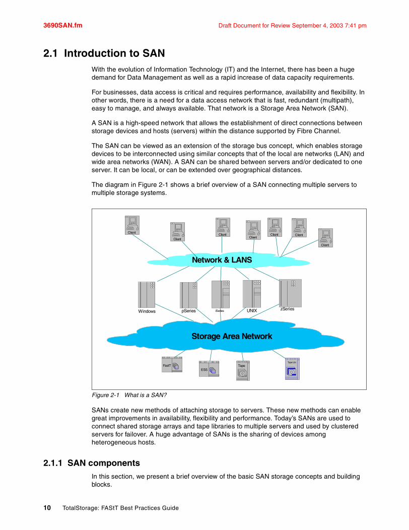
The diagram in Figure 2-1 shows a brief overview of a SAN connecting multiple servers to multiple storage systems.
Figure 2-1 What is a SAN?
SANs create new methods of attaching storage to servers. These new methods can enable great improvements in availability, flexibility and performance. Today’s SANs are used to connect shared storage arrays and tape libraries to multiple servers and used by clustered servers for failover. A huge advantage of SANs is the sharing of devices among heterogeneous hosts.
2.1.1 SAN componentsIn this section, we present a brief overview of the basic SAN storage concepts and building blocks.
Network & LANS
Storage Area Network
zSeriesiSeries UNIXpSeriesWindows
TapeESS
Client
FastT
Client ClientClient Client
Client
Tape Libr.
Client
10 TotalStorage: FAStT Best Practices Guide

Draft Document for Review September 4, 2003 7:41 pm 3690SAN.fm
Figure 2-2 SAN components
SAN serversThe server infrastructure is the underlying reason for all SAN solutions. This infrastructure includes a mix of server platforms such as Windows, UNIX (and its various flavors) and z/OS
SAN storageThe storage infrastructure is the foundation on which information relies, and therefore must support a company’s business objectives and business model. In this environment simply deploying more and faster storage devices is not enough. A SAN infrastructure provides enhanced network availability, data accessibility, and system manageability. It is important to remember that a good SAN begins with a good design. The SAN liberates the storage device so it is not on a particular server bus, and attaches it directly to the network. In other words, storage is externalized and can be functionally distributed across the organization. The SAN also enables the centralization of storage devices and the clustering of servers, which has the potential to make for easier and less expensive, centralized administration that lowers the total cost of ownership (TCO).
Fibre Channel Today, Fibre Channel is the architecture on which most SAN implementations are built. Fibre Channel is a technology standard that allows data to be transferred from one network node to another at very high speeds. Current implementations transfer data at 1 Gb/s or 2 Gb/s (10 Gb/s data rates have already been tested).
Fibre Channel was completely developed through industry cooperation, unlike SCSI, which was developed by a vendor, and submitted for standardization after the fact.
Some people refer to Fibre Channel architecture as the Fibre version of SCSI. Fibre Channel is an architecture used to carry IPI traffic, IP traffic, FICON traffic, FCP (SCSI) traffic, and
Shared Storage Devices
SAN Components
Heterogeneous Servers
Bridge
Hub
SwitchDirector
zSeries
Windows
iSeries
UNIX
LINUX
pSeries
Tape
ESS
FastT SSA
JBOD
Chapter 2. FAStT and Storage Area Network 11
3690SAN.fm Draft Document for Review September 4, 2003 7:41 pm
possibly traffic using other protocols, all on the standard FC transport. An analogy could be Ethernet, where IP, NETBIOS, and SNA are all used simultaneously over a single Ethernet adapter, since these are all protocols with mappings to Ethernet. Similarly, there are many protocols mapped onto FC.
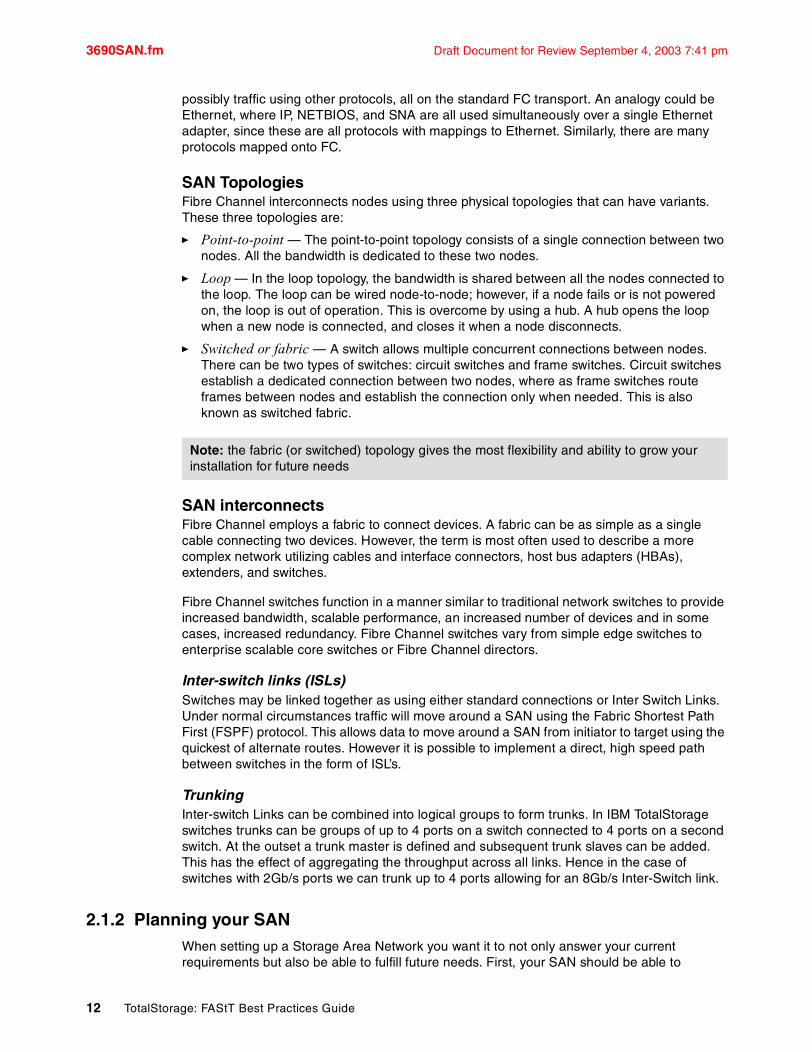
SAN TopologiesFibre Channel interconnects nodes using three physical topologies that can have variants. These three topologies are:
� Point-to-point — The point-to-point topology consists of a single connection between two nodes. All the bandwidth is dedicated to these two nodes.
� Loop — In the loop topology, the bandwidth is shared between all the nodes connected to the loop. The loop can be wired node-to-node; however, if a node fails or is not powered on, the loop is out of operation. This is overcome by using a hub. A hub opens the loop when a new node is connected, and closes it when a node disconnects.
� Switched or fabric — A switch allows multiple concurrent connections between nodes. There can be two types of switches: circuit switches and frame switches. Circuit switches establish a dedicated connection between two nodes, where as frame switches route frames between nodes and establish the connection only when needed. This is also known as switched fabric.
SAN interconnectsFibre Channel employs a fabric to connect devices. A fabric can be as simple as a single cable connecting two devices. However, the term is most often used to describe a more complex network utilizing cables and interface connectors, host bus adapters (HBAs), extenders, and switches.
Fibre Channel switches function in a manner similar to traditional network switches to provide increased bandwidth, scalable performance, an increased number of devices and in some cases, increased redundancy. Fibre Channel switches vary from simple edge switches to enterprise scalable core switches or Fibre Channel directors.
Inter-switch links (ISLs)Switches may be linked together as using either standard connections or Inter Switch Links. Under normal circumstances traffic will move around a SAN using the Fabric Shortest Path First (FSPF) protocol. This allows data to move around a SAN from initiator to target using the quickest of alternate routes. However it is possible to implement a direct, high speed path between switches in the form of ISL’s.
TrunkingInter-switch Links can be combined into logical groups to form trunks. In IBM TotalStorage switches trunks can be groups of up to 4 ports on a switch connected to 4 ports on a second switch. At the outset a trunk master is defined and subsequent trunk slaves can be added. This has the effect of aggregating the throughput across all links. Hence in the case of switches with 2Gb/s ports we can trunk up to 4 ports allowing for an 8Gb/s Inter-Switch link.
2.1.2 Planning your SANWhen setting up a Storage Area Network you want it to not only answer your current requirements but also be able to fulfill future needs. First, your SAN should be able to
Note: the fabric (or switched) topology gives the most flexibility and ability to grow your installation for future needs
12 TotalStorage: FAStT Best Practices Guide

Draft Document for Review September 4, 2003 7:41 pm 3690SAN.fm
accommodate a growing demand in storage (it is estimated that it doubles every 2 years). Secondly, your SAN must be able to keep up with the constant evolution of technology and resulting hardware upgrades and improvements. It is estimated that you will have to upgrade your storage installation every 2- 3 years.
Compatibility among different pieces of equipment is crucial when planning your installation; the important question is what device works with what, but also who has tested and certified (desirable) what equipment.
When designing a SAN storage solution, it is good practice to complete the following steps:
1. Produce a statement that outlines the solution requirements that can be used to determine the type of configuration you need. It should also be used to cross-check that the solution design delivers the basic requirements. The statement should have easily defined bullet points covering the requirements, for example:
– Required capacity– Required redundancy levels– Backup and restore windows– Type of data protection needed– Network backups– LAN free backups– Serverless backups– FlashCopy– Remote Volume Mirroring– Host and operating system types to be connected to SAN– Number of host connections required
2. Produce a hardware checklist. It should cover such items that you require you to:
– Ensure that the minimum hardware requirements are met. – Make a complete list of the hardware requirements including the required premium
options.– Ensure your primary and secondary storage subsystems are properly configured. – Ensure that your Fibre Channel switches and cables are properly configured. The
remote mirroring links must be in a separate zone.
3. Produce a software checklist to cover all the required items that need to be certified and checked. It should include such items that require you to:
– Ensure that data on the primary and secondary storage subsystems participating in remote volume mirroring is backed up.
– Ensure that the correct version of firmware and storage-management software are installed.
– Ensure that the Remote Volume Mirror option is enabled on both the primary and secondary storage subsystems.
– Ensure that the Remote Volume Mirror option is activated and that a mirror repository logical drive is created for each controller all participating storage subsystem.
– Ensure that the required primary and secondary logical drives are created on the primary and remote storage subsystems.
For more complete information regarding Storage Area Networks, please refer to the following Redbook:
– IBM SAN Survival Guide,SG24-6143-01 – IBM SAN Survival Guide featuring the IBM 2109, SG24-6127-00
Chapter 2. FAStT and Storage Area Network 13

3690SAN.fm Draft Document for Review September 4, 2003 7:41 pm
2.2 ZoningA zone is a group of fabric-connected devices arranged into a specified grouping. Zones can vary in size depending on the number of fabric connected devices, and devices can belong to more than one zone.
Typically, you can use zones to do the following:
� Administer security: you can use zones to provide controlled access to fabric segments and to establish barriers between operating environments. For example, isolate systems with different uses or protect systems in a heterogeneous environment.
� Customize environments: you can use zones to create logical subnets of the fabric to accommodate closed user groups or to create functional areas within the fabric. For example, include selected devices within a zone for the exclusive use of zone members, or create separate test or maintenance areas within the fabric.
� Optimize IT resources: you can use zones to consolidate equipment, logically, for IT efficiency, or to facilitate time-sensitive functions. For example create a temporary zone to back up non-member devices.
Figure 2-3 shows four zones which allow traffic between two fibre channel devices each.
Without zoning, failing devices that are no longer following the defined rules of fabric behavior might attempt to interact with other devices in the fabric. This type of event would be similar to an ethernet device causing broadcast storms or collisions on the whole network instead of being restricted to one single segment or switch port. With zoning, these failing devices cannot affect devices outside of their zone.
Figure 2-3 IBM SAN switch zoning
14 TotalStorage: FAStT Best Practices Guide
Draft Document for Review September 4, 2003 7:41 pm 3690SAN.fm
2.2.1 Zone typesA zone member may be specified using one of the following notations:
– Node World Wide Name
– Port World Wide Name
– Physical Fabric port number
The following describes the zones types:
� Port Level Zone: A zone containing members specified by switch ports (domain ID, port number) only. Port level zoning is enforced by hardware in the switch
� WWN Zone: A zone containing members specified by device World Wide Name (WWNs) only. WWN zones are hardware enforced in the switch.
� Mixed Zone: A zone containing some members specified by WWN and some members specified by switch port. Mixed zones are software enforced through the fabric name server.
Zones can be hard (hardware enforced), soft (advisory), or broadcast zone. In a hardware enforced zone, zone members can be specified by physical port number, or through WWN, but not within the same zone. A software enforced zone is created when a port member and WWN members are in the same zone.
Hardware enforced zonesIn a hardware enforced zone, all zone members can be specified as switch ports or WWN; any number of ports or WWN’s in the fabric can be configured to the zone. When a zone member is specified by port number or WWN, the individual device port or WWN is included in the zone. Hard zones are not necessarily position independent anymore. If WWN’s are used exclusively in a zone, new devices can be attached without regard to physical location. In hard zones; the switch hardware ensures that there is no data transferred between unauthorized zone members. However, devices can transfer data between ports within the same zone. Consequently, hard zoning provides security.
Software enforced zonesIn a software enforced zone, at least one zone member is specified by WWN and one member is specified as a port. In this way, you have a mixed zone that is software enforced. When a device logs in, it queries the name server for devices within the fabric. If zoning is in effect, only the devices in the same zone(s) are returned. Other devices are hidden from the name server query reply. When a mixed zone of WWNs and ports are specified all ports on the specified device are included in the zone. Software enforced zones are created when a combination of WWNs and ports are used. When using software enforced zones, the switch does not control the data transfer and there is no guarantee of data being transferred from unauthorized zone members. Use Software zoning where flexibility is required, and security is ensured by the co-operating hosts.
Tip: It is often debated whether one should share HBAs for disk storage and tape connectivity. A rule of thumb is separate the tape backup from the rest of your storage by zoning and move the tape traffic to a separate HBA and create an separate zone. That will avoid LIPa resets from other loop devices to reset the tape device and potentially interrupt a running backup.
a. LIP stands for Loop Initialization Process and indicates the initialization process that is usedwhen the operating system initiates a bus reset routine
Chapter 2. FAStT and Storage Area Network 15
3690SAN.fm Draft Document for Review September 4, 2003 7:41 pm
Broadcast zoneOnly one broadcast zone can exist within a fabric. It is named “broadcast” and it is used to specify those nodes that are to receive broadcast traffic. This type is hardware enforced; the switch controls data transfer to a port.
2.3 FAStT physical installation considerations In this section we review some topics of importance when planning for the physical installation of a FAStT system
2.3.1 Rack considerationsThe FAStT and possible expansions are mounted in rack enclosures.
Preparing the physical siteBefore you install a rack enclosure, be sure you:
� Understand the rack specifications and requirements� Prepare a layout for the racks� Prepare the physical site
General planning� Determine:
– The size of the floor area required by the equipment (see “Product Specifications”)
• Floor-load capacity• Space needed for expansion• Location of columns
– The power and environmental requirements.
� Create a floor plan to check for clearance problems.
� Make a full-scale template (if necessary) of the rack and carry it along the access route to check for potential clearance problems through doorways and passage ways, around corners, and in elevators.
� Provide space for storage cabinets, card files, desks, communication facilities, daily storage of tapes, and other supplies.
� Store all spare materials that can burn in properly designed and protected areas.
Rack LayoutTo be sure you have enough space for the racks, create a floor plan before installing the racks. You might need to prepare and analyze several layouts before choosing the final plan.
If you are installing the racks in two or more stages, prepare a separate layout for each stage.
Consider the following when you make a layout:
� The flow of work and personnel within the area.� Operator access to units, as required.
Note: You do not explicitly specify a type of enforcement for a zone. The type of zone enforcement (hardware or software) depends on the type of member it contains (WWNs or ports).
16 TotalStorage: FAStT Best Practices Guide

Draft Document for Review September 4, 2003 7:41 pm 3690SAN.fm
� If the rack is on a raised floor, position it over a cooling register. The bottom of the rack is open to facilitate cooling.
� If the rack is not on a raised floor:– The maximum cable lengths– The need for such things as cable guards and ramps to protect equipment and
personnel� Location of any planned safety equipment.� Expansion.
Begin with an accurate drawing of the installation area (blueprints and floor plans are appropriate).
Be sure to include the following on the layout:
� Service clearances required for each rack or suite of racks.� If the equipment is on a raised floor:
– Things that might obstruct cable routing– The height of the raised floor
� If the equipment is not on a raised floor:– The placement of cables to minimize obstruction– If the cable routing is indirectly between racks (such as along walls or suspended), the
amount of additional cable� Location of:
– Power receptacles– Air conditioning equipment and controls– File cabinets, desks, and other office equipment– Room emergency power-off controls– All entrances, exits, windows, columns, and pillars
Review the final layout to ensure that cable lengths are not too long and that the racks have enough clearance
You need at least 152 cm. (60 in.) of space between 42-U rack suites. This space is necessary for opening the front and rear doors, and for installing and servicing the rack. It also allows air circulation for cooling the equipment in the rack. All vertical rack measurements are given in rack units (U). One U is equal to 4.45 cm. (1.75 in.). The U levels are marked on labels on one front mounting rail and one rear mounting rail. Figure 2-4 shows an example of the required service clearances for a 9306-900 42U rack.
Chapter 2. FAStT and Storage Area Network 17

3690SAN.fm Draft Document for Review September 4, 2003 7:41 pm
Figure 2-4 Example of Service Clearances for 9306-900 Rack
2.3.2 Cable management and labeling Cable management and labeling for solutions utilizing racks, n-node clustering and fibre channel is increasingly important in Intel-processor solutions. Cable management and labeling needs have expanded from the traditional labeling of network connections to management and labeling of most cable connections between your servers, disk subsystems, multiple network connections, power and video subsystems. Examples of solutions include fibre channel configurations, n-node cluster solutions, multiple unique solutions located in the same rack or across multiple racks and solutions where components may not be physically located in the same room, building or site.
Why is more detailed cable management required?The necessity for detailed cable management and labeling is due to the complexity of today's configurations, potential distances between solution components and the increased number of cable connections required to attach additional value-add computer components. Benefits from more detailed cable management and labeling include: ease of installation, ongoing solutions/systems management and increased serviceability.
Solutions installation and ongoing management is easier to achieve when your solution is correctly and consistently labeled. Labeling helps make it possible to know what system you are installing or managing. For example, when it is necessary to access the CD-ROM of a particular system and you are working from a centralized management console. It is also helpful to be able to visualize where each server is when completing custom configuration tasks such as node naming and assigning IP addresses.
18 TotalStorage: FAStT Best Practices Guide

Draft Document for Review September 4, 2003 7:41 pm 3690SAN.fm
Cable management and labeling improve service and support by reducing problem determination time ensuring the correct cable is disconnected when necessary. Labels will assist in quickly identifying which cable needs to be removed when connected to a device such as a hub which may have multiple connections of the same cable type. Labels also help identify which cable to remove from a component. This is especially important when a cable connects two components which are not in the same rack, room, or even the same site.
Cable planningSuccessful cable management planning includes 3 basic activities: site planning (before your solution is installed), cable routing and cable labeling.
Site planningAdequate site planning completed before your solution is installed will result in a reduced chance of installation problems. Significant attributes covered by site planning are location specifications, electrical considerations, raised/non-raised floor determinations, and determination of cable lengths. Consult the documentation of your solution for special site planning considerations. IBM Netfinity Racks document site planning information in the IBM Netfinity Rack Planning & Installation Guide (part number 24L8055).
Cable routingEffective cable routing will allow you to keep your solution's cables organized, reduce the risk of damaging cables and allow for affective service & support. To assist with cable routing, IBM recommends the following:
When installing cables to devices mounted on sliding rails:
– Run the cables neatly along equipment cable-management arms and tie the cables to the arms. (Obtain the cable ties locally.)
– Take particular care when attaching fiber optic cables to the rack. Refer to the instructions included with your fiber optic cables for guidance on minimum radius, handling, and care of fiber optic cables.
– Run the cables neatly along the rack rear corner posts.
– Use cable ties to secure the cables to the corner posts.
– Make sure the cables cannot be pinched or cut by the rack rear door
– Run internal cables that connect devices in adjoining racks through the open rack sides.
– Run external cables through the open rack bottom.
– Leave enough slack so the device can be fully extended without putting a strain on the cables.
– Tie the cables so the device can be retracted without pinching or cutting the cables.
To avoid damage to your fiber-optic cables, follow these guidelines:
– Do not route the cable along a folding cable-management arm.
– When attaching to a device on slides, leave enough slack in the cable so that it does not bend to a radius smaller than 76 mm. (3 in.) when extended or become pinched when retracted.
Note: Do not use cable-management arms for Fibre cables.
Chapter 2. FAStT and Storage Area Network 19
3690SAN.fm Draft Document for Review September 4, 2003 7:41 pm
– Route the cable away from places where it can be snagged by other devices in the rack.
– Do not overtighten the cable straps or bend the cables to a radius smaller than 76 mm (3 in.).
– Do not put excess weight on the cable at the connection point and be sure that it is well supported.
Additional information for routing cables with IBM Netfinity Rack products can be found in the IBM Netfinity Rack Planning & Installation Guide (part number 24L8055). This publication includes pictures providing more detail on recommended cable routing.
Cable labelingWhen labeling your solution, follow the below tips:
– As you install cables in the rack, label each cable with appropriate identification.
– Remember to attach labels to any cables you replace.
– Document deviations from the label scheme you use. Keep a copy with your Change Control Log book.
Whether using a simple or complex scheme, the label should always implement a format including these attributes:
– Function (optional) – Location information should be broad to specific (e.g. site/building to specific port on a
server or hub). – The optional Function row helps identify the purpose of the cable (i.e. Ethernet vs.
Token Ring or between multiple networks).
Other cabling mistakesSome of the most common mistakes include:
� Leaving cables hanging from connections with no support � Not using dust caps � Not keeping connectors clean � Leaving them dragging on the floor for people to kick and trip over
2.4 FAStT CablingIn the sections that follow, we explain the typical recommended cabling configuration for the FAStT600 and FAStT900 respectively.
2.4.1 FAStT600 Cabling Configuration The basic design point of a FAStT Storage Server is to have hosts directly attach it.
The best practice for attaching host systems to your FAStT storage is to use fabric attach, with fibre switches as explained in the second part of this section. For simple installation it is however possible and acceptable to direct attach the FAStT600 to a single host with two HBAs.
20 TotalStorage: FAStT Best Practices Guide

Draft Document for Review September 4, 2003 7:41 pm 3690SAN.fm
FAStT600 direct attachThe FAStT600 offers fault tolerance on both HBAs and FAStT controllers. At the same time, you can get higher performance, since the dual controller allow for distribution of the load. See the left hand side of Figure 2-5 on page 21.
Figure 2-5 FAStT600 cabling configuration
FAStT600 supports a dual node cluster without using a switch. This is shown on the right hand side of Figure 2-5 and in Figure 2-6. This provides the lowest priced solution for 2-node clusters due to four Fibre Channel host ports
.
Figure 2-6 FAStT600 cluster setup configuration without fibre switches
FAStT600 Fibre switch attached The recommended configuration is to connect the FAStT600 to Fibre switches to expand its connection for multi-servers, as shown in Figure 2-7.
As seen in the diagram multiple hosts can access a single FAStT system but also have the capability of accessing data on any FAStT subsystem within the SAN. This configuration allows more flexibility and growth capability within the SAN: attachment of new systems is made easier when adopting such structured cabling techniques.
Host system with 2 HBAs
Host system with 2 HBAs
Host system with 2 HBAs
FAStT600FAStT600
controller A controller B controller A controller B
Chapter 2. FAStT and Storage Area Network 21
3690SAN.fm Draft Document for Review September 4, 2003 7:41 pm
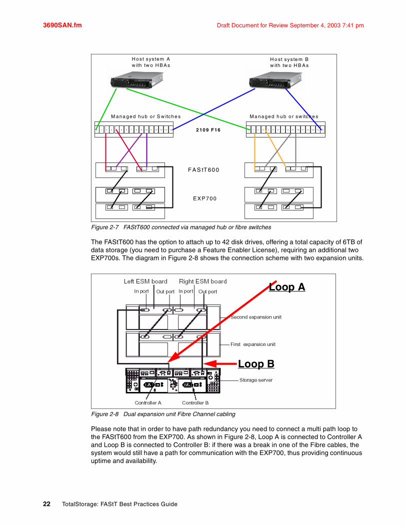
Figure 2-7 FAStT600 connected via managed hub or fibre switches
The FAStT600 has the option to attach up to 42 disk drives, offering a total capacity of 6TB of data storage (you need to purchase a Feature Enabler License), requiring an additional two EXP700s. The diagram in Figure 2-8 shows the connection scheme with two expansion units.
Figure 2-8 Dual expansion unit Fibre Channel cabling
Please note that in order to have path redundancy you need to connect a multi path loop to the FAStT600 from the EXP700. As shown in Figure 2-8, Loop A is connected to Controller A and Loop B is connected to Controller B: if there was a break in one of the Fibre cables, the system would still have a path for communication with the EXP700, thus providing continuous uptime and availability.
1 20 3 4 5 6 7 9 108 11 12 13 14 1 5 1 20 3 4 5 6 7 9 108 1 1 1 2 1 3 1 4 15
E X P 700
2 10 9 F16
H os t sys tem A w ith tw o H B A s
H o st sys te m B w ith tw o H B A s
F A S tT 60 0
M ana ged hub o r S w itche s M a naged h ub o r sw itche s
Loop A
Loop B
22 TotalStorage: FAStT Best Practices Guide

Draft Document for Review September 4, 2003 7:41 pm 3690SAN.fm
2.4.2 FAStT900 Cabling Configuration Figure 2-9 illustrates the rear view of a FAStT900. There are up to four host mini-hubs (two are standard). The mini-hubs numbered 1 and 3 correspond to the top controller (controller A), and mini-hubs 2 and 4 correspond to the bottom controller (controller B).
Figure 2-9 Rear View of the FAStT900 Storage server
To ensure redundancy, you must connect each host to both RAID controllers (A and B).
Figure 2-10 illustrates a direct connection of hosts (each host must be equipped with two Host Adapters)
Figure 2-10 Connecting hosts directly to the controller
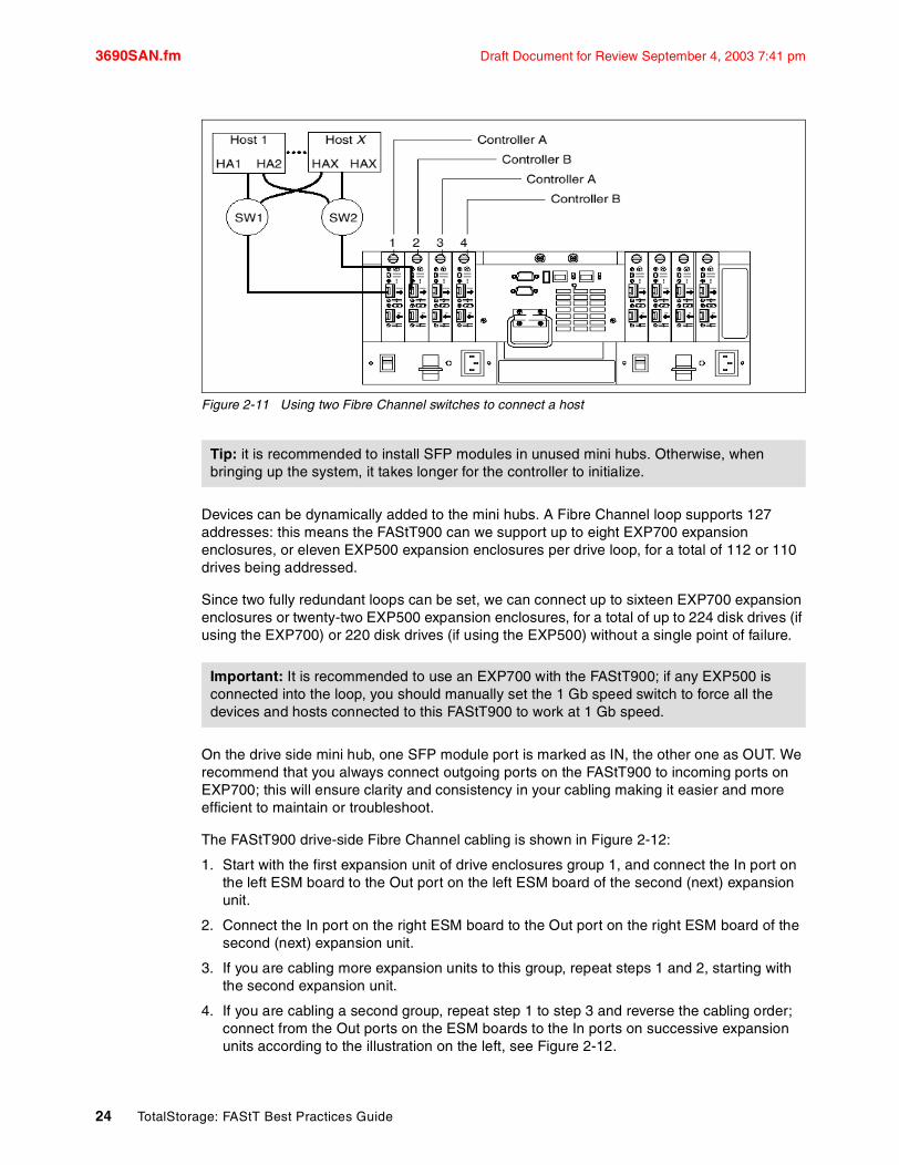
Figure 2-11 illustrates the recommended dual path configuration using a fibre channel switches (rather than direct attachment). Host 1 contains two HBAs that are connected to host mini hubs. To configure a host with dual path redundancy, connect the first host bus adapter (HA1) to SW1 and HA2 to SW2. Then connect SW1 to host mini hub 1 and SW2 to host mini hub 2.
Note: Please note that although storage remains accessible, Storage Manager will report a path failure and request you to check for a faulty cable connection to the FAStT.
Chapter 2. FAStT and Storage Area Network 23
3690SAN.fm Draft Document for Review September 4, 2003 7:41 pm
Figure 2-11 Using two Fibre Channel switches to connect a host
Devices can be dynamically added to the mini hubs. A Fibre Channel loop supports 127 addresses: this means the FAStT900 can we support up to eight EXP700 expansion enclosures, or eleven EXP500 expansion enclosures per drive loop, for a total of 112 or 110 drives being addressed.
Since two fully redundant loops can be set, we can connect up to sixteen EXP700 expansion enclosures or twenty-two EXP500 expansion enclosures, for a total of up to 224 disk drives (if using the EXP700) or 220 disk drives (if using the EXP500) without a single point of failure.
On the drive side mini hub, one SFP module port is marked as IN, the other one as OUT. We recommend that you always connect outgoing ports on the FAStT900 to incoming ports on EXP700; this will ensure clarity and consistency in your cabling making it easier and more efficient to maintain or troubleshoot.
The FAStT900 drive-side Fibre Channel cabling is shown in Figure 2-12:
1. Start with the first expansion unit of drive enclosures group 1, and connect the In port on the left ESM board to the Out port on the left ESM board of the second (next) expansion unit.
2. Connect the In port on the right ESM board to the Out port on the right ESM board of the second (next) expansion unit.
3. If you are cabling more expansion units to this group, repeat steps 1 and 2, starting with the second expansion unit.
4. If you are cabling a second group, repeat step 1 to step 3 and reverse the cabling order; connect from the Out ports on the ESM boards to the In ports on successive expansion units according to the illustration on the left, see Figure 2-12.
Tip: it is recommended to install SFP modules in unused mini hubs. Otherwise, when bringing up the system, it takes longer for the controller to initialize.
Important: It is recommended to use an EXP700 with the FAStT900; if any EXP500 is connected into the loop, you should manually set the 1 Gb speed switch to force all the devices and hosts connected to this FAStT900 to work at 1 Gb speed.
24 TotalStorage: FAStT Best Practices Guide

Draft Document for Review September 4, 2003 7:41 pm 3690SAN.fm
5. Connect the Out port of drive side mini-hub 4 (left most drive side) to the In port on the left ESM board of the last expansion unit in the drive enclosures group 1.
6. Connect the In port of drive-side mini-hub 3 to the Out port on the right ESM board of the first expansion unit in the drive enclosures group 1.
7. If you are cabling a second group, connect the Out port of the drive-side mini-hub 2 to the In port on the left ESM board of the first expansion unit in drive enclosures group 2; then, connect the In port of the drive-side Mini-Hub 1 (rightmost drive side) to the Out port on the right ESM board of the last expansion unit in Drive enclosures group 2.
8. Ensure that each expansion unit has a unique ID (switch setting) and that the left and right ESM board switch settings on each expansion unit are identical.
Figure 2-12 FAStT900 Drive-side Fibre Channel cabling
Tip: Figure 2-12 on page 25 shows that there are four drive loops (A,B,C and D). The best practice is to distribute the storage (the EXP units) configuration among all of the four available drive mini hubs for redundancy and better performance.
When you have multiple expansion enclosures, it is always best to create RAID arrays across the expansion enclosures for channel protection and redundancy.
Chapter 2. FAStT and Storage Area Network 25

3690SAN.fm Draft Document for Review September 4, 2003 7:41 pm
2.5 Hot-scaling the IBM TotalStorage FAStT Series Hot-scaling is the ability to dynamically reconfigure drive modules to meet changing system requirements. For example, when capacity requirements on a FAStT900 system increase, new drive modules can be added to the existing mini hub pair or added to the new or unused mini hub pair with no disruption to data availability or interruption of I/O.
Figure 2-13 shows the back of a FAStT900 and how it is connected to two EXP700 expansion enclosures (DM1 and DM2 in the picture).
Figure 2-13 Hot-scale technology
2.5.1 Adding capacityLet’s step through the process of adding an expansion enclosure (DM3). Keep in mind that the equipment has been mounted and the each tray has been given a unique identifier. The drive bays are empty and drives will be added after the loop is completed.
First, add drive module (DM) DM3 on drive loop A by connecting a new cable (colored red in Figure 2-14).
Next, move the cable on loop B from DM2 to DM3, as indicated by the yellow cable in the diagram.
Finally, add a cable from DM2 to DM3 (as indicated by the Blue cable in the diagram) to complete loop B.
DM 1
DM 2
DM 3
Drive Loop A Drive Loop B
FASt T900
Tip: when adding drives to an expansion unit, do not add more than two drives at a time.
26 TotalStorage: FAStT Best Practices Guide

Draft Document for Review September 4, 2003 7:41 pm 3690SAN.fm
Figure 2-14 Capacity Scaling
Because drive loops A and B are redundant, there is no interruption to I/O throughout this re-configuration. Once the new drive module installation is complete, additional volumes may be configured on the new drives while the system is online or Dynamic Capacity Expansion may be used to stripe the existing volumes across the new drives.
2.5.2 Increasing bandwidthYou can increase bandwidth by moving expansion enclosures to a new or unused mini hub pair (this doubles the drive side bandwidth).
This re-configuration may also be accomplished with no disruption to data availability or interruption of I/O.
Let’s assume that the initial configuration is the one depicted in Figure 2-15 on page 28.
We are going to move DM 2 to the unused mini-hub pair on the FAStT900. Refer to Figure 2-16 on page 28.
DM 1
DM 2
DM 3
Drive Loop A Drive Loop B
FASt T900
Yellow
BlueRed
Chapter 2. FAStT and Storage Area Network 27
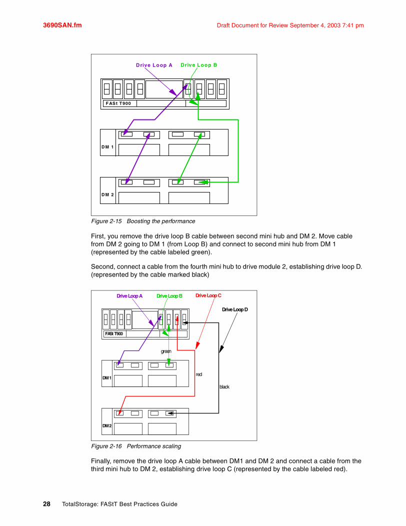
3690SAN.fm Draft Document for Review September 4, 2003 7:41 pm
Figure 2-15 Boosting the performance
First, you remove the drive loop B cable between second mini hub and DM 2. Move cable from DM 2 going to DM 1 (from Loop B) and connect to second mini hub from DM 1 (represented by the cable labeled green).
Second, connect a cable from the fourth mini hub to drive module 2, establishing drive loop D. (represented by the cable marked black)
Figure 2-16 Performance scaling
Finally, remove the drive loop A cable between DM1 and DM 2 and connect a cable from the third mini hub to DM 2, establishing drive loop C (represented by the cable labeled red).
D M 1
D M 2
Drive Loop A
F ASt T900
Driv e Loop B
FASt T900
DM 1
DM 2
Drive Loop A Drive Loop B
Drive Loop D
Drive Loop C
green
red
black
28 TotalStorage: FAStT Best Practices Guide
Draft Document for Review September 4, 2003 7:41 pm 3690Planning.fm
Chapter 3. FAStT Planning Tasks
Careful planning is essential to any new storage installation.
Choosing the right equipment and software, and also knowing what the right settings are for your installation can be challenging: every installation has to answer and accommodate specific requirements and there can be numerous variations in the solution.
Well-thought design and planning before jumping into implementation will get you most of your investment for the present and protect it for the future.
This chapter of the book is aimed at providing guidelines to help you in the planning process. Some recommendations in this chapter come directly from the authors experience with various FAStT installations at customer sites.
© Copyright IBM Corp. 2003. All rights reserved. 29

3690Planning.fm Draft Document for Review September 4, 2003 7:41 pm
3.1 General considerationsDuring the planning process, you will need to answer numerous questions about your environment:
� What Operating system am I going to use (existing or new installation)?� What applications will access the storage subsystem?� What are these applications hardware and software requirements?� What will be the physical layout of the installation? Only local site or remote sites as well?� What performance do I need?� What redundancy do I need? (e.g. do I need off-site mirroring?)� What compatibility issues do I need to address� How much does it cost� What are my SAN requirements?� What hardware will I need to buy?
The list of questions is not exhaustive, and as you can see some go beyond simply configuring the FAStT Storage Server.
An important question and primary concern for most users is how to configure their storage subsystem for the best performance. There is no simple answer, no golden rule of thumb for storage performance optimization that is valid in every environment and for every particular situation.Furthermore, it is crucial to keep in mind that storage is just a piece of the overall solution. Other components of the solution, as represented in Figure 3-1 can be responsible for bad performance. Tuning the whole system is an iterative process: every time you make a change to one of the components, you must reevaluate all of the other components.
Figure 3-1 Iterative steps for system performance tuning
Here, we will only cover the disk I/O subsystem.
30 TotalStorage: FAStT Best Practices Guide

Draft Document for Review September 4, 2003 7:41 pm 3690Planning.fm
3.2 Physical components and characteristicsIn this section, we review elements related to physical characteristics of an installation like fiber cables, fiber channel adapters, and other elements related to the structure of the storage system and disks, such as arrays. controller ownership, segment size, storage partitioning, caching, hot spare drives and remote volume mirroring.
3.2.1 CablingIn Section 2.3, “FAStT physical installation considerations” on page 16 we have discussed the importance of adequate cable management and labeling. In this section, with review some essential characteristics or specifications of fibre cables.
Cable typesFibre cables are basically available in multi-mode fiber (MMF) or single mode fiber (SMF). Both types can support shortwave as well as longwave.
Multi-mode fiber (MMF) allows light to disperse in the fiber so that it takes many different paths, bouncing of the edge of the fiber repeatedly to finally get to the other end (multi-mode means multiple paths for the light). The light taking these different paths gets to the other end of the cable at slightly different times (different path - different distance - different time). The receiver has to figure which signals go together as they all come flowing in: the maximum distance is limited by how “blurry” the original signal has become. The thinner the glass the less the signals “spread out” and the further you can go and still figure out what is what on the receiving end. This dispersion (called modal dispersion) is the critical factor in determining the maximum distance a high speed signal can go; it is more relevant than the attenuation of the signal (from an engineering standpoint it is easy enough to increase the power level of the transmitter and/or the sensitivity of your receiver, but too much dispersion cannot be decoded no matter how strong the incoming signals are).
Single mode fiber (SMF) is so thin (9 microns) that the light “can barely squeeze through” and basically tunnels through the center of the fiber using only one path (or mode). This behavior can be explained (although not simply) through the laws of optics and physics. The result is that since there is only one path that the light takes to the receiver, there is no “dispersion confusion” at the receiver. However, the concern with single mode fiber is attenuation of the signal
.
Table 3-1 Cable type overview
Fiber type Speed Maximum Distance
9 micron SMF (longwave) 1Gb 10km
9 micron SMF (longwave) 2Gb 2km
50 micron MMF (shortwave) 1Gb 500m
50 micron MMF (shortwave) 2Gb 300m
62.5 micron MMF (shortwave)
1Gb 175m/300m
62.5 micron MMF (shortwave)
2Gb 90m/150m
Chapter 3. FAStT Planning Tasks 31

3690Planning.fm Draft Document for Review September 4, 2003 7:41 pm
Interoperability of 1Gb and 2Gb devicesThe Fibre Channel standard specifies a procedure for speed auto-detection. Thus, if a 2Gb port on a switch or device is connected to a 1Gb port it will negotiate down and run the link at 1Gb. If there are two 2Gb ports on either end of a link then the negotiation will end up running the link at 2Gb if the link is up to spec. A link that is too long, or “dirty” could end up running at 1Gb even with 2Gb ports at either end so watch your distances and make sure your fiber is good
3.2.2 Fibre Channel adaptersWe review here two topics related to Fibre Channel adapters:
� Placement on the host system bus� Distributing the load among several adapters
Host system busToday, there is a choice of high-speed adapters for connecting disk drives; obviously, fast adapters can provide better performance, but you must be careful not to put all the high-speed adapters on a single system bus; otherwise the computer bus becomes the performance bottleneck.
It is recommended to distribute high-speed adapters across several busses. When you use PCI adapters, make sure you first review your system specifications: some systems include a PCI adapter placement guide.
The number of adapters you can install depends obviously on the number of PCI slots available on your server but also depends on what traffic volume to expect on your SAN.
Do you want only failover capabilities on the storage side (one HBA, two paths) or do you want to share the workload and have fully redundant path failover with multiple adapters and over multiple paths. In general all operating systems support two paths to the FAStT Storage Server. Windows 2000 and Windows 2003 support up to four paths to the storage controller.
As illustrated in Figure 3-2, AIX can also support four paths to the controller, provided there are two partitions accessed within the FAStT subsystem.
Figure 3-2 AIX - four paths to FAStT
32 TotalStorage: FAStT Best Practices Guide
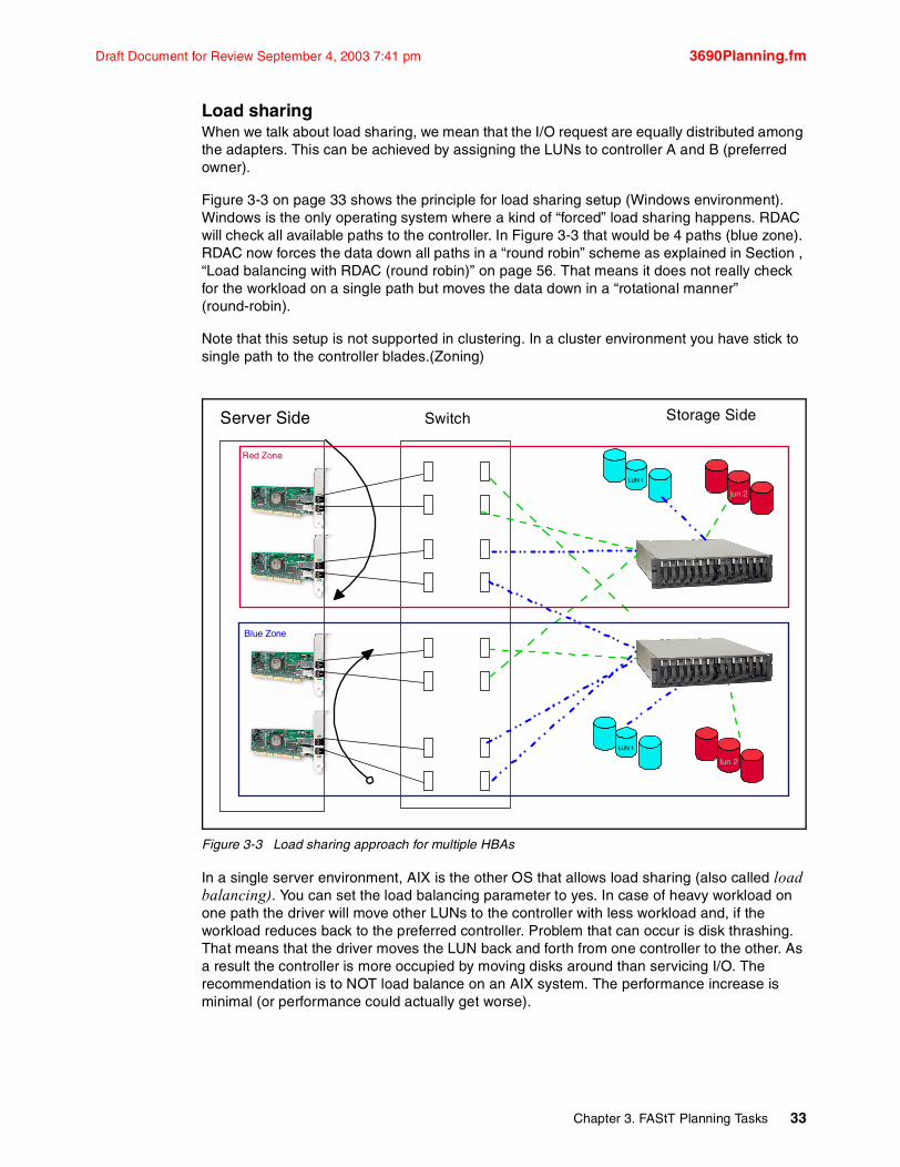
Draft Document for Review September 4, 2003 7:41 pm 3690Planning.fm
Load sharingWhen we talk about load sharing, we mean that the I/O request are equally distributed among the adapters. This can be achieved by assigning the LUNs to controller A and B (preferred owner).
Figure 3-3 on page 33 shows the principle for load sharing setup (Windows environment). Windows is the only operating system where a kind of “forced” load sharing happens. RDAC will check all available paths to the controller. In Figure 3-3 that would be 4 paths (blue zone). RDAC now forces the data down all paths in a “round robin” scheme as explained in Section , “Load balancing with RDAC (round robin)” on page 56. That means it does not really check for the workload on a single path but moves the data down in a “rotational manner” (round-robin).
Note that this setup is not supported in clustering. In a cluster environment you have stick to single path to the controller blades.(Zoning)
Figure 3-3 Load sharing approach for multiple HBAs
In a single server environment, AIX is the other OS that allows load sharing (also called load balancing). You can set the load balancing parameter to yes. In case of heavy workload on one path the driver will move other LUNs to the controller with less workload and, if the workload reduces back to the preferred controller. Problem that can occur is disk thrashing. That means that the driver moves the LUN back and forth from one controller to the other. As a result the controller is more occupied by moving disks around than servicing I/O. The recommendation is to NOT load balance on an AIX system. The performance increase is minimal (or performance could actually get worse).
Server Side Switch Storage Side
LUN 1
lun 2
LUN 1
lun 2
Red Zone
Blue Zone
Chapter 3. FAStT Planning Tasks 33

3690Planning.fm Draft Document for Review September 4, 2003 7:41 pm
3.2.3 Planing your Storage Structure and PerformanceWe review and discuss successively the RAID levels, array size, array configuration and channel protection.
An array is a set of drive that the system logically groups together to provide one or more logical drives to an application host or cluster.
When defining arrays, you often have to compromise among capacity, performance, and redundancy.
\We will go through the different RAID level and explain why we would chose this particular setting in this particular situation and the reader can hopefully draw he or her own conclusion.
RAID LevelsPerformance varies based on the RAID level that is set. Use the Performance Monitor to obtain logical drive application read and write percentages.
RAID 0 - For Performance: RAID 0 is also known as data striping. It is well-suited for program libraries requiring rapid loading of large tables, or more generally, applications requiring fast access to read-only data, or fast writing. RAID 0 is only designed to increase performance; there is no redundancy, so any disk failures require reloading from backups. Select RAID Level 0 for applications that would benefit from the increased performance capabilities of this RAID Level. Never use this level for critical applications that require high availability.
RAID 1 - For Availability/Good Read Response Time: RAID 1 is also known as disk mirroring. It is most suited to applications that require high data availability, good read response times, and where cost is a secondary issue. The response time for writes can be somewhat slower than for a single disk, depending on the write policy; the writes can either be executed in parallel for speed or serially for safety. Select RAID Level 1 for applications with a high percentage of read operations and where the cost is not the major concern.
Because the data is mirrored, the capacity of the logical drive when assigned RAID level-1 is 50% of the array capacity.
Some recommendation in using RAID-1 are:
– Use RAID-1 for the disks that contain our operating system. It is a good choice because the operating system can usually fit on one disk.
– Use RAID-1 for transaction logs. Typically, the database server transaction log can fit on one disk drive. In addition, the transaction log performs mostly sequential writes. Only rollback operations cause reads from the transaction logs. Thus, we can achieve a high rate of performance by isolating the transaction log on its own RAID-1 array.
– Use write caching on RAID-1 arrays. Because a RAID-1 write will not complete until both writes have been done (two disks), performance of writes can be improved through the use of a write cache. When using a write cache, be sure it is battery-backed up.
Tip: Unless you have unique requirements, it is highly recommended to let the system automatically create arrays. This usually ensures the most optimal balance between capacity, performance and redundancy. A manual configuration will typically not have the most optimal settings
34 TotalStorage: FAStT Best Practices Guide
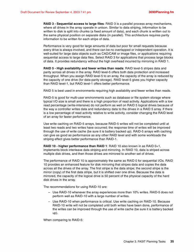
Draft Document for Review September 4, 2003 7:41 pm 3690Planning.fm
RAID 3 - Sequential access to large files: RAID 3 is a parallel process array mechanisms, where all drives in the array operate in unison. Similar to data striping, information to be written to disk is split into chunks (a fixed amount of data), and each chunk is written out to the same physical position on separate disks (in parallel). This architecture requires parity information to be written for each stripe of data.
Performance is very good for large amounts of data but poor for small requests because every drive is always involved, and there can be no overlapped or independent operation. It is well-suited for large data objects such as CAD/CAM or image files, or applications requiring sequential access to large data files. Select RAID 3 for applications that process large blocks of data. It provides redundancy without the high overhead incurred by mirroring in RAID 1.
RAID 5 - High availability and fewer writes than reads: RAID level-5 stripes data and parity across all drives in the array. RAID level-5 offers both data protection and increased throughput. When you assign RAID level-5 to an array, the capacity of the array is reduced by the capacity of one drive (for data-parity storage). RAID level-5 gives you higher capacity than RAID level-1, but RAID level-1 offers better performance.
RAID 5 is best used in environments requiring high availability and fewer writes than reads.
RAID-5 is good for multi-user environments such as database or file system storage where typical I/O size is small and there is a high proportion of read activity. Applications with a low read percentage (write-intensive) do not perform as well on RAID 5 logical drives because of the way a controller writes data and redundancy data to the drives in a RAID 5 array. If there is a low percentage of read activity relative to write activity, consider changing the RAID level of an array for faster performance.
Use write caching on RAID-5 arrays, because RAID-5 writes will not be completed until at least two reads and two writes have occurred; the response time of writes will be improved through the use of write cache (be sure it is battery backed up). RAID-5 arrays with caching can give as good as performance as any other RAID level and with some workloads the striping effect gives better performance than RAID-1.
RAID 10 - higher performance than RAID 1: RAID 10 also known in as RAID 0+1, implements block interleave data striping and mirroring. In RAID 10, data is striped across multiple disk drives, and then those drives are mirrored to another set of drives.
The performance of RAID 10 is approximately the same as RAID 0 for sequential I/Os. RAID 10 provides an enhanced feature for disk mirroring that stripes data and copies the data across all the drives of the array. The first stripe is the data stripe; the second stripe is the mirror (copy) of the first data stripe, but it is shifted over one drive. Because the data is mirrored, the capacity of the logical drive is 50 percent of the physical capacity of the hard disk drives in the array.
The recommendations for using RAID-10 are:
– Use RAID-10 whenever the array experiences more than 10% writes. RAID-5 does not perform well as RAID-10 with a large number of writes.
– Use RAID-10 when performance is critical. Use write caching on RAID-10. Because RAID-10 write will not be completed until both writes have been done, performance of the writes can be improved through the use of write cache (be sure it is battery backed up).
When comparing to RAID-5:
Chapter 3. FAStT Planning Tasks 35

3690Planning.fm Draft Document for Review September 4, 2003 7:41 pm
– RAID-10 writes a single block through two writes, RAID-5 requires two reads (read original data and parity) and two writes. Random writes are significantly faster on RAID-10.
– RAID-10 rebuild takes less time than RAID-5 rebuild. If a real disk fails, RAID-10 rebuilds it by copying all the data on the mirrored disk to a spare. RAID-5 rebuilds a failed disk by merging the contents of the surviving disks in an array and writing the result to a spare.
RAID-10 is the best fault tolerant solution in terms of protection and performance, but it comes at a cost: you must purchase twice the number of disks that are necessary with RAID-0.
To Summarize:
Table 3-2 RAID levels comparison
Note: Based on the respective level, RAID offers the following performance results:
– RAID 0 offers high performance, but does not provide any data redundancy. – RAID 1 offers high performance for write-intensive applications. – RAID 3 is good for large data transfers in applications, such as multimedia or
medical imaging, that write and read large sequential chunks of data. – RAID 5 is good for multi-user environments, such as database or file system
storage, where the typical I/O size is small and there is a high proportion of read activity.
– RAID 10 offers higher performance than RAID 1
RAID Description APP Advantage Disadvantage
0 Stripes data across multiple drives
IOPS MB/s
Performance due to parallel operation of the access
No redundancy. One drive fails, data is lost
1 Disk's data is mirrored to another drive
IOPS Performance as multiple requests can be fulfilled simultaneously
Storage costs are doubled
10 Data is striped across multiple drives and mirrored to same number of disks
IOPS Performance as multiple requests can be fulfilled simultaneously
Storage costs are doubled
3 Drives operated independently with data and parity blocks distributed across all drives in the group
MB/s High performance for large, sequentially access files (image, video, graphical)
Degraded performance with 8-9 I/O threads, random IOPS, smaller more numerous IOPS
5 Drives operated independently with data and parity blocks distributed across all drives in the group
IOPSMB/s
Good for reads, small IOPS, many concurrent IOPS and random I/Os
Writes are particularly demanding
36 TotalStorage: FAStT Best Practices Guide

Draft Document for Review September 4, 2003 7:41 pm 3690Planning.fm
Array SizeDepending on the firmware level of your FAStT Storage Server you can have
� In SM 8.3 an array size of up to 2TB raw space
� In SM 8.4 an array size up to 22 TB raw space.
Raw space means the total space available on your disk. Depending on your RAID level the usable space will be between 50% for Raid 1 and (N- 1)*drive capacity where N is the number of drives for RAID 5
Table 3-3 RAID level and performance
Note that there is a limit of 30 disks per array and disks in an array can span expansion units.
Array ConfigurationBefore you can start using the physical disk space, you must configure it. That is, you divide your disk drives into arrays and create one or more logical drives inside each array.
In simple configurations, you can use all of your drive capacity with just one array and create all of your logical drives in that unique array. However, this presents the following drawbacks:
� If you experience a drive failure, the rebuild process will affect all logical drives and the overall system performance will go down.
� Read/ write operations of different logical drive still being made to the same physical hard drives.
Number of drivesThe more physical drives you have per array the shorter the access time for read and write I/O operations.
Tip: The first rule for the successful building of good performing storage solutions is to have enough physical space to create arrays and logical drives according to your needs
RAID Levels Data capacity1
Sequential IO performance2 Random IO performance2
Read Write Read Write
Single Disk n 6 6 4 4
RAID-0 n 10 10 10 10
RAID-1 n/2 7 5 6 3
RAID-5 n-1 7 73 7 4
RAID-10 n/2 10 9 7 6
Notes:1 In the data capacity, n refers to the number of equally sized disks in the array.2 10 = best, 1 = worst. We should only compare values within each column. Comparisons between column is not valid for this table.3 With the write back setting enabled
Note: If you have a FAStT Storage Server 600 you will need to purchase a Feature Enabler Licence to expand your storage to the maximum of 42 drives.
Chapter 3. FAStT Planning Tasks 37

3690Planning.fm Draft Document for Review September 4, 2003 7:41 pm
You can determine how many physical drives should be associated with a RAID controller by looking at disk transfer rates (rather than at the megabytes per second). For example, if a hard disk drive is capable of 75 nonsequential (random) I/Os per second, then about 26 hard disk drives working together could -theoretically- produce 2,000 nonsequential I/Os per second, or enough to hit the maximum I/O handling capacity of a single RAID controller. If the hard disk drive can sustain 150 sequential I/Os per second, it then takes only about 13 hard disk drives working together to produce the same 2,000 sequential I/Os per second and keep the RAID controller running at maximum throughput.
RAID controllersAs explained before, under heavy load I/O, bottlenecks can occur at different levels; hard disk drive I/O is the most common one but possible RAID controllers and PCI bus bottlenecks must also be taken into account.
You can get an indication of how many RAID controllers can be installed on a PCI bus by dividing the I/O processing capacity of the PCI bus by the I/O processing capacity of the RAID controller. For example if the drives associated with a RAID controller average a throughput of 40MB/sec and the PCI bus can sustain 133MB/sec, then you can attach three (133 divided by 40) RAID controllers to the PCI bus
Note that most large servers come with more than one PCI bus, which increases the number of RAID controllers that can be installed in a single server.
Channel Protection PlaningChannel protection is a good way to make your system more resilient against hardware failures. Channel Protection means you spread your arrays across multiple enclosures rather than in one enclosure so that a failure of a single enclosure does not takes a whole array offline. Further benefit is a performance increase since the I/O request are processed by multiple ESM boards along multiple paths (loop side)
Figure 3-4 Channel no channel protection vs. channel protection
Tip: More physical disks for the same overall capacity gives you:
� performance: by doubling the number of the physical drives, you can expect up to 50% increase in throughput performance.
� flexibility: using more physical drives gives you more flexibility to build arrays and logical drives according to your needs
� data capacity: when using RAID-5 logical drives more data space is available with smaller physical drives because less space (capacity of on drive) is used for parity.
38 TotalStorage: FAStT Best Practices Guide

Draft Document for Review September 4, 2003 7:41 pm 3690Planning.fm
When using automatic configuration feature as mentioned in Chapter 3.2.3, “Planing your Storage Structure and Performance” on page 34 the tool will always choose channel protection across all available enclosures. See Figure 3-5
Figure 3-5 Automatic configuration feature
3.2.4 Logical drives and controller ownershipLogical drives, sometimes simply referred to as volumes or LUNs (LUN is in fact Logical Unit Number and represents the number a hosts uses to access the logical drive), are the logical segmentation of arrays. A logical drive is a logical structure you create on a storage subsystem for data storage. A logical drive is defined over a set of drives called an array, and has a defined RAID level and capacity (see Section , “RAID Levels” on page 34). The drive boundaries of the array are hidden to the host computer.
The IBM TotalStorage FAStT Storage Server provides great flexibility in terms of configuring arrays and logical drives. However, when assigning logical volumes to the systems it is very important to remember that the FAStT Storage Server uses a preferred controller ownership approach for communicating with LUNs: this means that every LUN is owned by only one controller. It is thus important at the system level to make sure that traffic is correctly balanced among controllers. This is a fundamental principle for a correct setting of the storage system.
Balancing traffic is unfortunately not always a trivial task. For example if an application requires large disk space to be located and accessed in one chunk, it becomes harder to balance traffic by spreading the smaller volumes among controllers.
Also, typically the load across controllers and logical drives are constantly changing. The logical drives and data accessed at any given time depend on which applications and users are active during that time period. Hence the importance of monitoring the system (see Section 5.2, “Controlling the performance impact of maintenance tasks” on page 74)
Chapter 3. FAStT Planning Tasks 39
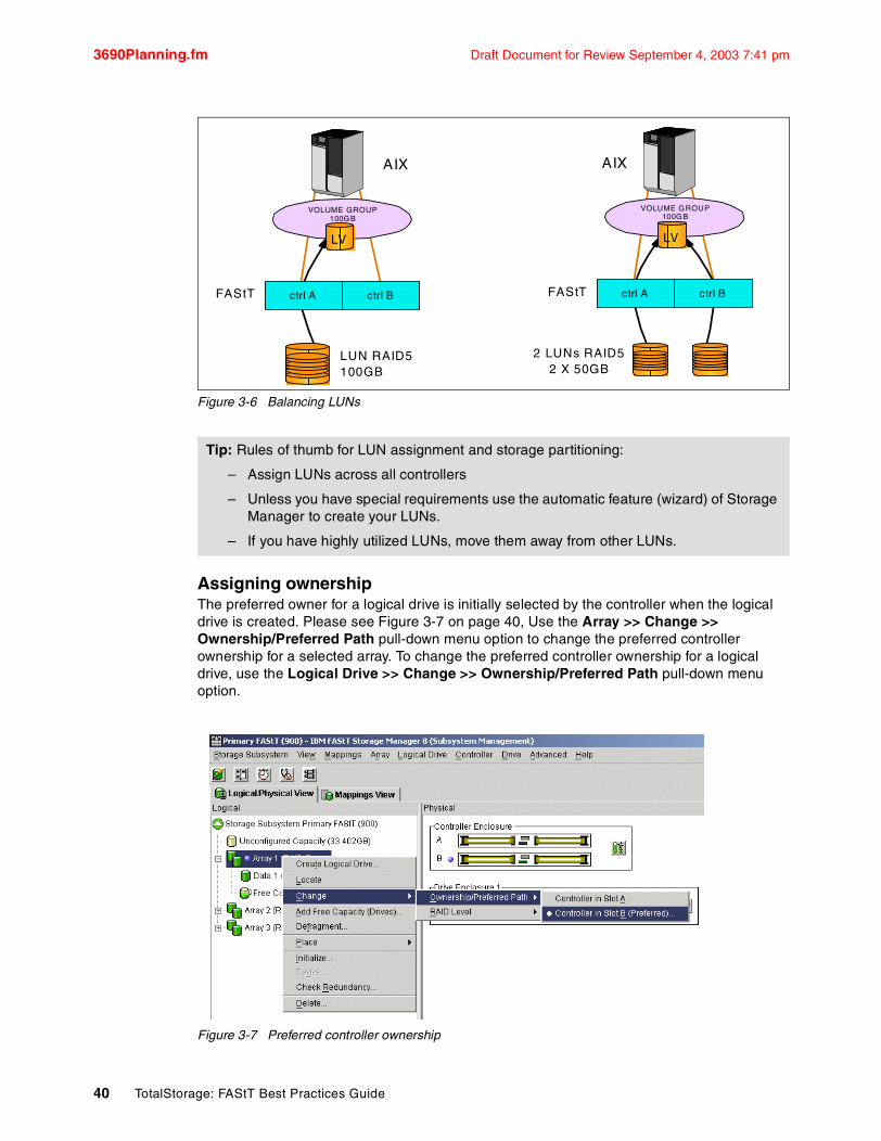
3690Planning.fm Draft Document for Review September 4, 2003 7:41 pm
Figure 3-6 Balancing LUNs
Assigning ownershipThe preferred owner for a logical drive is initially selected by the controller when the logical drive is created. Please see Figure 3-7 on page 40, Use the Array >> Change >> Ownership/Preferred Path pull-down menu option to change the preferred controller ownership for a selected array. To change the preferred controller ownership for a logical drive, use the Logical Drive >> Change >> Ownership/Preferred Path pull-down menu option.
Figure 3-7 Preferred controller ownership
Tip: Rules of thumb for LUN assignment and storage partitioning:
– Assign LUNs across all controllers
– Unless you have special requirements use the automatic feature (wizard) of Storage Manager to create your LUNs.
– If you have highly utilized LUNs, move them away from other LUNs.
ctrl A ctrl BFAStT
VOLUME GROUP 100GB
LUN RAID5100GB
ctrl A ctrl BFAStT
2 LUNs RAID52 X 50GB
AIX AIX
VOLUME GROUP 100GB
LV LV
40 TotalStorage: FAStT Best Practices Guide
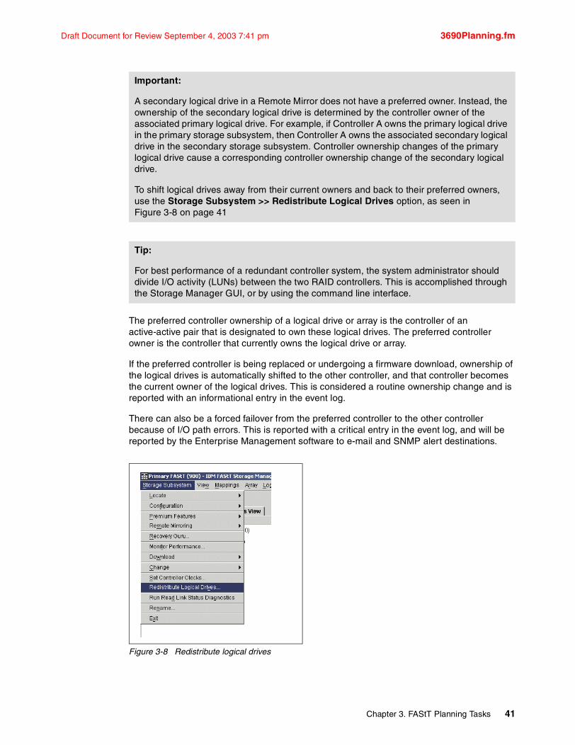
Draft Document for Review September 4, 2003 7:41 pm 3690Planning.fm
The preferred controller ownership of a logical drive or array is the controller of an active-active pair that is designated to own these logical drives. The preferred controller owner is the controller that currently owns the logical drive or array.
If the preferred controller is being replaced or undergoing a firmware download, ownership of the logical drives is automatically shifted to the other controller, and that controller becomes the current owner of the logical drives. This is considered a routine ownership change and is reported with an informational entry in the event log.
There can also be a forced failover from the preferred controller to the other controller because of I/O path errors. This is reported with a critical entry in the event log, and will be reported by the Enterprise Management software to e-mail and SNMP alert destinations.
Figure 3-8 Redistribute logical drives
Important:
A secondary logical drive in a Remote Mirror does not have a preferred owner. Instead, the ownership of the secondary logical drive is determined by the controller owner of the associated primary logical drive. For example, if Controller A owns the primary logical drive in the primary storage subsystem, then Controller A owns the associated secondary logical drive in the secondary storage subsystem. Controller ownership changes of the primary logical drive cause a corresponding controller ownership change of the secondary logical drive.
To shift logical drives away from their current owners and back to their preferred owners, use the Storage Subsystem >> Redistribute Logical Drives option, as seen in Figure 3-8 on page 41
Tip:
For best performance of a redundant controller system, the system administrator should divide I/O activity (LUNs) between the two RAID controllers. This is accomplished through the Storage Manager GUI, or by using the command line interface.
Chapter 3. FAStT Planning Tasks 41

3690Planning.fm Draft Document for Review September 4, 2003 7:41 pm
3.2.5 Segment SizeThe choice of a segment size can have major influence on performance in both IOPS and throughput. Large segment sizes increase the request rate (IOPS) by allowing multiple disk drives to respond to multiple requests. Small segment size increases the data transfer rate (MB/s) by allowing multiple disk drives to participate in one I/O request. Use a small segment size relative to the I/O size to increase sequential performance.
You can use the performance monitor (see Section 5.1, “Performance monitoring and tuning” on page 72) to evaluate how a given segment size affects the workload. Use the following guidelines:
� If the typical I/O size is larger than the segment size, increase the segment size in order to minimize the number of drives needed to satisfy an I/O request. This is especially true in a multi-user, database, or file system storage environment. Using a single drive for a single request leaves other drives available to simultaneously service other requests.
� If we are using the logical drive in a single-user, large I/O environment (such as for multimedia application storage), performance is optimized when a single I/O request can be serviced with a single data stripe (the segment size multiplied by the number of drives in the array that are used for I/O). In this case, multiple disks are used for the same request, but each disk is only accessed once.
� Normally, a small segment size is used for databases, normal sizes for file server and large segment sizes for multimedia applications.
� If we increase the segment size we gain more throughput.
3.2.6 Storage PartitioningStorage partitioning adds a high level of flexibility to the FAStT Storage Server. It allows you to connect to the same storage server multiple and heterogeneous host systems, either in standalone or clustered mode. Storage partitioning was introduced in SM 7.10
Without storage partitioning, the logical drives configured on a FAStT Storage Server can only be accessed by a single host system or by a single cluster. This can surely lead to inefficient use of the storage server hardware.
Storage partitioning, on the other hand, allows you to create sets, containing the hosts with their host bus adapters and the logical drives. We call these sets storage partitions. Now the host systems can only access their assigned logical drives, just as if these logical drives were locally attached to them.
Tips: The possible segment size available are 8k,16k,32k,64k,128k,256k.
– Storage Manager sets a default block size of 64 KB.– For database application block size between 4 - 16 Kb have shown to be more
effective.– In large file environment like on media streaming or CAD 128k above are
recommended.– For web server, file and print server the range should be between 16-64 kb.
Note: You should do performance testing in you environment before you go in production with a given segment size: segment size can be dynamically changed, but only by rewriting the data - which consumes bandwidth and impacts performance. Plan this carefully to avoid the redo.
42 TotalStorage: FAStT Best Practices Guide

Draft Document for Review September 4, 2003 7:41 pm 3690Planning.fm
Storage partitioning lets you map and mask LUNs (that’s why it’s also referred to as LUN masking). That means once you have assigned that LUN to a host it is hidden to all other hosts connected to the same Storage Server. Therefore, the access to that LUN is exclusively reserved for that host. It is a good practice to do your storage partitioning prior to connecting to multiple hosts: operating systems such as AIX or Windows 2000 like to write their signatures to any device they can access.
Heterogeneous host support means that the host systems can run different operating systems. But be aware that all the host systems within a particular storage partition must run the same operating system, as all host systems within a particular storage partition have unlimited access to all logical drives in this partition. Thus, file systems on these logical drives must be compatible with host systems. To ensure this, the best way is running the same operating system on all hosts within the same partition. Some operating systems may be able to mount foreign file systems.
Storage partition topology is a collection of topological elements (default group, host groups, hosts, and host ports) shown as nodes in the topology view of the mappings view. You must define the various topological elements if you want to define specific logical drive-to-LUN mappings for host groups and/or hosts.
In order to do the storage partitioning correctly you need the WWN of your HBS. Mapping is done on a WWN basis. Depending on your HBA you can obtain the WWN either from the BIOS or FAStT MSJ tool if you have Qlogic cards. IBM 6228 and 6392 have a sticker on the back of the card and so have JNIC adapter for Solaris.
If you are connected to a HUB or switch check the Name Server Table of the HUB or switch to identify the HBS’s WWN.
When planning your partitioning, keep in mind that:
� in a cluster environment, you need to use host groups
� partitions are purchasable option
See Section 4.2.3, “Configuring storage partitioning” on page 68 for details on how to define your storage partitioning
3.2.7 Cache parametersCache memory is an area of temporary volatile storage (RAM) on the controller that has a faster access time than the drive media. This cache memory is shared for read and write operations.
Efficient use of the RAID controller cache is essential for good performance of the FAStT storage server.
The diagram shown in Figure 3-9 on page 44 on is a schematic model of the major elements of a disk storage system - elements through which data moves (as opposed to other elements
Note: The are limitations as to how many logical drives you can map per host. FAStT allows up to 32 LUNs per partition (including the access LUN) and a maximum of two partitions per host. Keep these limitations in mind when planning your installation.
Note: Not you will need backup software which takes care of masking the LUNs so that only one host at the time can write to that LUN
Chapter 3. FAStT Planning Tasks 43

3690Planning.fm Draft Document for Review September 4, 2003 7:41 pm
such as power supplies). In the model, these elements are organized into eight vertical layers: four layers of electronic components shown inside the dotted ovals and four layers of paths (i.e., wires) connecting adjacent layers of components to each other. Starting at the top in this model, there are some number of host computers (not shown) that connect (over some number of paths) to host adapters. The host adapters connect to cache components. The cache components in turn connect to disk adapters that in turn connect to disk drives.
Here is how a read I/O request is handled in this model. A host issues a read I/O request that is sent over a path (such as a Fibre Channel) to the disk system. The request is received by a disk system host adapter. The host adapter checks whether the requested data is already in cache in which case it is immediately sent back to the host. If the data is not in cache, the request is forwarded to a disk adapter that reads the data from the appropriate disk and copies the data into cache. The host adapter sends the data from cache to the requesting host.
Figure 3-9 Conceptual model of disk caching
Most (hardware) RAID controllers have some form of read and/or write caching. You should obviously plan to take advantage of this caching capabilities as they enhance the effective I/O capacity of the disk subsystem. The principle of these controller-based caching mechanisms is to gather smaller and potentially nonsequential I/O requests coming in from the host server (e.g. SQL Server) and try to batch them with other I/O requests; consequently, the I/O requests are sent as larger (32 KB to 128 KB) and possibly sequential requests to the hard disk drives. The RAID controller cache arranges incoming I/O requests by making the best use of the hard disks underlying I/O processing ability. This increases the disk I/O throughput.
There are many different settings (related to caching) that come into play. When implementing a FAStT Storage Sever as part of a whole solution you should plan at least one week of performance testing and monitoring to adjust the settings.
The FAStT Storage Manager utility enables you to configure various cache settings:
� Read caching� Cache block size� Cache read-ahead multiplier� Write caching� Write-back and write-through mode
. . .
. . .
. . .
. . .
. . .
. . .
. . .
. . .
paths to hosts 1...n
1...n
1...n
1...n
1...n
1...n
1...n
1...n
paths to cache
paths to adapters
paths to disks
host adapters
cache
disk adapters
disk drives
44 TotalStorage: FAStT Best Practices Guide
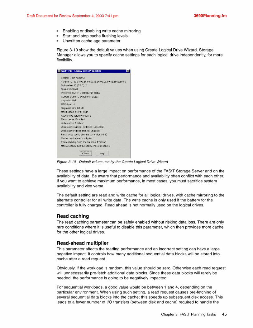
Draft Document for Review September 4, 2003 7:41 pm 3690Planning.fm
� Enabling or disabling write cache mirroring � Start and stop cache flushing levels� Unwritten cache age parameter.
Figure 3-10 show the default values when using Create Logical Drive Wizard. Storage Manager allows you to specify cache settings for each logical drive independently, for more flexibility.
Figure 3-10 Default values use by the Create Logical Drive Wizard
These settings have a large impact on performance of the FAStT Storage Server and on the availability of data. Be aware that performance and availability often conflict with each other. If you want to achieve maximum performance, in most cases, you must sacrifice system availability and vice versa.
The default setting are read and write cache for all logical drives, with cache mirroring to the alternate controller for all write data. The write cache is only used if the battery for the controller is fully charged. Read ahead is not normally used on the logical drives.
Read cachingThe read caching parameter can be safely enabled without risking data loss. There are only rare conditions where it is useful to disable this parameter, which then provides more cache for the other logical drives.
Read-ahead multiplierThis parameter affects the reading performance and an incorrect setting can have a large negative impact. It controls how many additional sequential data blocks will be stored into cache after a read request.
Obviously, if the workload is random, this value should be zero. Otherwise each read request will unnecessarily pre-fetch additional data blocks. Since these data blocks will rarely be needed, the performance is going to be negatively impacted.
For sequential workloads, a good value would be between 1 and 4, depending on the particular environment. When using such setting, a read request causes pre-fetching of several sequential data blocks into the cache; this speeds up subsequent disk access. This leads to a fewer number of I/O transfers (between disk and cache) required to handle the
Chapter 3. FAStT Planning Tasks 45
3690Planning.fm Draft Document for Review September 4, 2003 7:41 pm
same amount of data, which is good for performance in sequential environment. A value that is too high can cause an overall performance decrease because the cache is filled with read ahead data that is never used.
Use the performance monitor to watch the cache hit rate for a logical drive to find a proper value.
Write cachingThe write caching parameter allows the storage subsystem to cache write data instead of writing it directly to the disks. This can improve performance significantly especially for environments with random writes such as databases. For sequential writes, the performance gain varies with the size of the data written. If the logical drive is only used for read access, it may improve overall performance to disable the write cache for this logical drive. Then no cache memory is reserved for this logical drive.
Write cache mirroringFAStT write cache mirroring provides the integrity of cached data if a RAID controller fails. This is excellent from a high availability perspective, but it decreases performance. The data is mirrored between controllers across the drive-side FC loop. This competes with normal data transfers on the loop. It is recommended to keep controller write cache mirroring enabled for data integrity reason in case of a controller failure
By default, a write cache is always mirrored to the other controller to ensure proper contents, even if the logical drive moves to the other controller. Otherwise the data of the logical drive can be corrupted if the logical drive is shifted to the other controller and the cache still contains unwritten data. If you turn off this parameter, you risk data loss in the case of a controller failover, which may also be caused by a path failure in your fabric.
The cache of the FAStT Storage Server is protected, by a battery, against power loss. If the batteries are not fully charged, for example, just after powering on, the controllers automatically disable the write cache. If you enable the parameter, the write cache is used, even if no battery backup is available, resulting in a higher risk of data loss.
Write-back caching and write-throughIf you configure write-through, it means that writing operations do not use cache at all. The data is always going to be written directly to the disk drives. Setting this parameter frees up cache for reading (since the cache is shared for read and write operations).
Write-back caching can also increase performance of write operations. The data is not written straight to the disk drives; it is only written to the cache. From the application perspective, this is much faster than waiting for the disk write operation to complete. Therefore, you can expect a significant gain in application writing performance. It is the responsibility of the cache controller to eventually flush the unwritten cache entries to the disk drives.
Write-back mode appears to be faster than write-through mode, since it increases performance of both reads and writes. But is not always true because it depends on the disk access pattern and workload.
A lightly loaded disk subsystem usually works faster in write-back mode, but when the workload is high, the write cache may become inefficient. As soon as the data is written to the cache, it has to be flushed to the disks in order to make room for new data arriving into cache. The controller would actually perform faster if the data went directly to the disks. In this case, writing the data to the cache is an unnecessary step that actually decreases throughput.
46 TotalStorage: FAStT Best Practices Guide

Draft Document for Review September 4, 2003 7:41 pm 3690Planning.fm
Starting and stopping cache flushing levelsThese two settings affect the way the cache controller handles unwritten cache entries. They are obviously only effective when you configure the write-back cache policy. Writing the unwritten cache entries to the disk drives is called flushing. You can configure the start and stop flushing level values. They are expressed as percentages of the entire cache capacity. When the number of unwritten cache entries reaches the start flushing value, the controller begins to flush the cache (write the entries to the disk drives). The flushing stops when the number of unwritten entries drops below the stop flush value. The controller always flushes the oldest cache entries first. Unwritten cache entries older than 20 seconds are flushed automatically.
A typical start flushing level is 80%. Very often the stop flushing level is set to 80%, too. This means the cache controller will not allow more than 80% of the entire cache size for write-back cache, but it will also try to keep as much of it as possible for this purpose. If you use such settings, you can expect a high amount of unwritten entries in the cache. This is good for writing performance, but be aware that it offers less data protection.
If you are concerned for data protection, you might want to use lower start and stop values. With these two parameters, you can actually tune your cache for either reading or writing performance.
Performance tests have shown that it is a good idea to use similar values for start and stop flushing levels. If the stop level value is significantly lower than the start value, this causes a high amount of disk traffic when flushing the cache. If the values are similar, then the controller only flushes the amount needed to stay within limits.
Cache block sizeThis is the size of the cache memory allocation unit and can be either 4K or 16K. By selecting the proper value for your particular situation, you can significantly improve the caching efficiency and performance. For example, if applications mostly access the data in small blocks up to 8K, but you use 16K for cache block size then each cache entry block is only partially populated. You will always occupy 16K in cache to store 8K (or less) of data. This means only up to 50% of cache capacity is effectively used to store the data. You can obviously expect lower performance. For random workloads and small data transfer sizes, 4K is better.
On the other hand, if the workload is sequential and you use large segment size, it is a good idea to use larger cache block size 16K. A larger block size means a lower number of cache blocks and reduces cache overhead delays. In addition, a larger cache block size requires fewer cache data transfers to handle the same amount of data.
3.2.8 Hot-spare drive A hot-spare drive is like a replacement drive installed in advance. Hot-spare disk drives provide additional protection that might prove to be essential in case of a disk drive failure in a fault tolerant array.
Note: There is no definitive recommendation as to how many hot-spares you should install but it is common practice to use a ratio of one hot-spare for two to three fully populated expansion enclosures (this proves to be sufficient because disk reliability has really improved nowadays).
Chapter 3. FAStT Planning Tasks 47

3690Planning.fm Draft Document for Review September 4, 2003 7:41 pm
When assigning disks as hot-spares, make sure they have enough storage capacity. If the failed disk drive is larger than the hot-spare, reconstruction is obviously not possible. You can find more information in Section 4.2.1, “Defining hot-spare drives” on page 66
3.2.9 Remote Volume MirroringThe Remote Volume Mirror option is a premium feature that comes with the IBM FAStT Storage Manager 8.4 software and is enabled by purchasing a premium feature key. The Remote Volume Mirror option is used for online, real-time replication of data between storage subsystems over a remote distance. Figure 3-11 on page 48.
Figure 3-11 Remote Volume Mirroring
The mirroring is managed by the storage subsystem controllers and is transparent to host machines and applications. You create one or more mirrored logical drive pairs that consist of a primary logical drive at the primary site and a secondary logical drive at a remote site. After you create the mirror relationship between the two logical drives, the controller owner of the primary logical drive copies all of the data from the primary logical drive to the secondary logical drive. This is called a full synchronization.
In the event of a disaster or unrecoverable error at one storage subsystem, the Remote Volume Mirror option enables you to promote a secondary storage subsystem to take over responsibility for normal input/output (I/O) operations.
A mirroring relationship is on a logical drive basis:
� Associates two logical drives (primary and secondary) using Storage Manager software.� Data is copied to secondary logical drive in background.
The mirroring is synchronous. The write must be completed to both volumes before the host receives an I/O complete.
A minimum of two storage subsystems is required. One storage subsystem can have primary volumes being mirrored to arrays on other storage subsystems and hold secondary volumes from other storage subsystems. Also note that since replication is managed on a per-logical
FCFabric
Primary Data Center Backup Data Center
Network Network
V3mV2V1 V3V2mV1m
StorageArray
SANSAN
StorageArray
48 TotalStorage: FAStT Best Practices Guide

Draft Document for Review September 4, 2003 7:41 pm 3690Planning.fm
drive basis, you can mirror individual logical drives in a primary storage subsystem to appropriate secondary logical drives in several different remote storage subsystems
Intersite with FlashCopy drives and tape backupThe highest availability configuration is fully redundant and includes two storage subsystems and four Fibre Channel switches connected with Inter Switch Links (ISLs) forming Fibre Channel fabrics, as shown in Figure 3-12. The primary storage subsystem and remote storage subsystem have a maximum connection distance of up to 10 km. (6.25 mi.).
Figure 3-12 Intersite High Availability Solution
Apart from the greater redundancy of dual switch fabric in each site, a greater number of host ports are now available, allowing greater flexibility in the use and connectivity.
Note: RVM requires one (and only one) link per controller. To RVM volumes on both controllers requires two host side ports (one per controller). I
RVM use dedicated host ports for the copying operations (there is no sharing of mini-hubs). For redundancy of the RVM link you actually need to account for two mini hubs.
Also a switch is required on each end of the fabric connecting the primary and secondary sites
FAStT 900
EXP 700
Primary Remote
Local Area Network/Wide Area Network
Host 1
HBA 1 HBA 2 HBA 1 HBA 2
RemoteSite
PrimarySite
ISL
Host 2
HBA 1 HBA 2
B-Mirror Link Zone
A-Mirror Link ZoneCtl B & Host ZoneCtl A & Host Zone
FabricZoning
ISL
Host 4
HBA 1 HBA 2
Host 3
FAStT 900
EXP 700
Chapter 3. FAStT Planning Tasks 49

3690Planning.fm Draft Document for Review September 4, 2003 7:41 pm
With this type of configuration, consider putting the primary drives on the remote site. This offers several advantages. The first is if the primary site fails, the standby servers in the secondary site can be attached to the original primary disk with a simple procedure.
With the primary drives on the remote site and the secondary drive in the local site give an up-to-date copy at all times, it is still possible through programming or human error to corrupt data and the data corruption to be mirrored to the secondary drives. You now have several different options. You can:
� Make a FlashCopy of the data on the primary drive.
� Make a tape backup of the data from the primary drive.
� Combine both where a FlashCopy is performed and then perform a tape backup of the copied drive.
3.3 Logical layerThe logical layer defines how the actual physical disk is seen by applications.
3.3.1 Planning for systems with LVM - AIX exampleMany modern UNIX operating systems implement the concept of a Logical Volume Manager (LVM) that can be used to manage the distribution of data on physical disk devices.
The LVM for AIX is a set of operating system commands, library subroutines, and other tools used to control physical disk resources by providing a simplified logical view of the available storage space. Some of the vendors offers LVM as a special product. The AIX LVM is an integral part of the base AIX operating system and is provided at no additional cost.
In this section we discuss the advantages of having the LVM in the system.
With the UNIX operating system which has LVM, the handling of disk-related I/O is based upon different functional levels, as shown in Figure.
Figure 3-13
The lowest level is the physical level and consists of device drivers accessing the physical disks and using the corresponding adapters. The next level is the logical level, managed by the Logical Volume Manager (LVM), which controls the physical disk resources. The LVM provides a logical mapping of disk resources to the application level. The application level can consist of either the journaled file system (JFS) or raw access (for example, used by relational database systems).
50 TotalStorage: FAStT Best Practices Guide
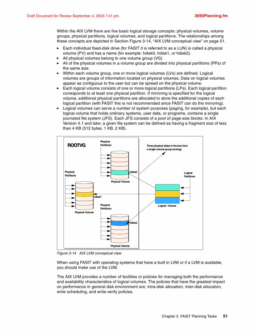
Draft Document for Review September 4, 2003 7:41 pm 3690Planning.fm
Within the AIX LVM there are five basic logical storage concepts: physical volumes, volume groups, physical partitions, logical volumes, and logical partitions. The relationships among these concepts are depicted in Section Figure 3-14, “AIX LVM conceptual view” on page 51.
� Each individual fixed-disk drive (for FAStT it is referred to as a LUN) is called a physical volume (PV) and has a name (for example: hdisk0, hdisk1, or hdisk2).
� All physical volumes belong to one volume group (VG)� All of the physical volumes in a volume group are divided into physical partitions (PPs) of
the same size.� Within each volume group, one or more logical volumes (LVs) are defined. Logical
volumes are groups of information located on physical volumes. Data on logical volumes appear as contiguous to the user but can be spread on the physical volume.
� Each logical volume consists of one or more logical partitions (LPs). Each logical partition corresponds to at least one physical partition. If mirroring is specified for the logical volume, additional physical partitions are allocated to store the additional copies of each logical partition (with FAStT this is not recommended since FAStT can do the mirroring).
� Logical volumes can serve a number of system purposes (paging, for example), but each logical volume that holds ordinary systems, user data, or programs, contains a single journaled file system (JFS). Each JFS consists of a pool of page-size blocks. In AIX Version 4.1 and later, a given file system can be defined as having a fragment size of less than 4 KB (512 bytes, 1 KB, 2 KB).
Figure 3-14 AIX LVM conceptual view
When using FAStT with operating systems that have a built in LVM or if a LVM is available, you should make use of the LVM.
The AIX LVM provides a number of facilities or policies for managing both the performance and availability characteristics of logical volumes. The policies that have the greatest impact on performance in general disk environment are; intra-disk allocation, inter-disk allocation, write scheduling, and write-verify policies.
PhysicalPartitions
PhysicalPartitions
PhysicalPartitions
Physical Volume
Physical Volume
Physical Volume
ROOTVGROOTVG
LogicalPartitions
Logical Volume
hdisk1
hdisk2
hdisk0
Three physical disks in the box forma single volume group (rootvg).
Chapter 3. FAStT Planning Tasks 51
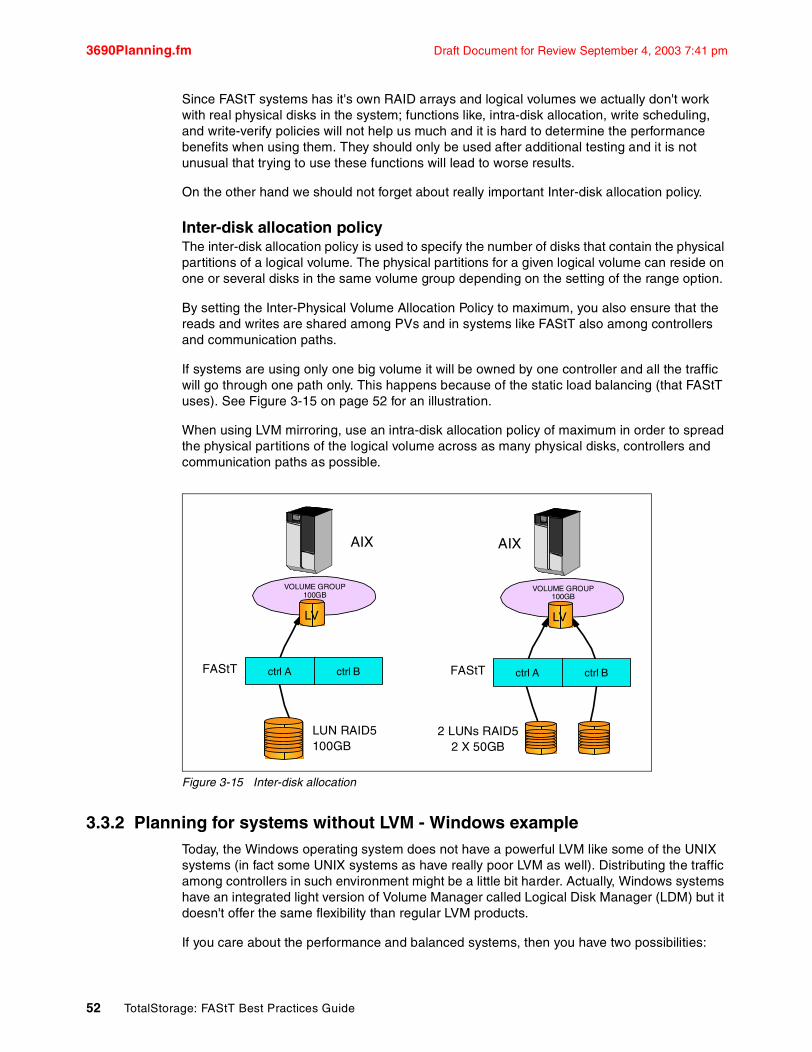
3690Planning.fm Draft Document for Review September 4, 2003 7:41 pm
Since FAStT systems has it's own RAID arrays and logical volumes we actually don't work with real physical disks in the system; functions like, intra-disk allocation, write scheduling, and write-verify policies will not help us much and it is hard to determine the performance benefits when using them. They should only be used after additional testing and it is not unusual that trying to use these functions will lead to worse results.
On the other hand we should not forget about really important Inter-disk allocation policy.
Inter-disk allocation policyThe inter-disk allocation policy is used to specify the number of disks that contain the physical partitions of a logical volume. The physical partitions for a given logical volume can reside on one or several disks in the same volume group depending on the setting of the range option.
By setting the Inter-Physical Volume Allocation Policy to maximum, you also ensure that the reads and writes are shared among PVs and in systems like FAStT also among controllers and communication paths.
If systems are using only one big volume it will be owned by one controller and all the traffic will go through one path only. This happens because of the static load balancing (that FAStT uses). See Figure 3-15 on page 52 for an illustration.
When using LVM mirroring, use an intra-disk allocation policy of maximum in order to spread the physical partitions of the logical volume across as many physical disks, controllers and communication paths as possible.
Figure 3-15 Inter-disk allocation
3.3.2 Planning for systems without LVM - Windows exampleToday, the Windows operating system does not have a powerful LVM like some of the UNIX systems (in fact some UNIX systems as have really poor LVM as well). Distributing the traffic among controllers in such environment might be a little bit harder. Actually, Windows systems have an integrated light version of Volume Manager called Logical Disk Manager (LDM) but it doesn't offer the same flexibility than regular LVM products.
If you care about the performance and balanced systems, then you have two possibilities:
ctrl A ctrl BFAStT
VOLUME GROUP 100GB
LUN RAID5100GB
ctrl A ctrl BFAStT
2 LUNs RAID52 X 50GB
AIX AIX
VOLUME GROUP 100GB
LV LV
52 TotalStorage: FAStT Best Practices Guide

Draft Document for Review September 4, 2003 7:41 pm 3690Planning.fm
� If you want UNIX-like capabilities, you can use Veritas Volume Manager which is the LVM tool for Windows. With this product you get several features that go beyond LDM. Volume Manager doesn't just replace the MMC snap-in, it adds a much more sophisticated set of storage services to Windows 2000. Once Windows 2000 is upgraded with Volume Manager, you are able to better manage multi-disk direct server-attached (DAS) storage, JBODs (just a bunch of disks), Storage Area Networks (SAN), or RAID.
The main feature that you get are sub-disks and disk groups. You can divide a dynamic disk into one or more sub-disks. A sub-disk is a set of contiguous disk blocks that represent a specific portion of a dynamic disk, which is mapped to a specific region of a physical disk. A sub-disk is a sub-section of a dynamic disk's public region. A sub-disk is the smallest unit of storage in Volume Manager. Therefore, sub-disks are the building blocks for Volume Manager arrays. A sub-disk can be compared to a physical partition.
Disk groups enable you to organize disks into logical collections. You assign disks to disk groups for management purposes, such as to hold the data for a specific application or set of applications. A disk group can be compared to a volume group. By using these concepts you can make a disk group with more LUNs that are spread among the controllers.
� Another possibility is to look at the application layer and try to spread databases or application data in smaller chunks that reside on LUNs owned by different controllers. So for example instead of one database defined as a 200GB file (on one 200GB LUN), define two database files of 100GB that side on different LUNs (owned by different controllers).
Tuning the applications and databases vary from product to product so we don't describe it here more in details.
Using Veritas Volume Manager and tuning the databases and applications go beyond the scope of this guide. You should look for more info on the application vendor sites or refer to the vendor documentation.
For Veritas Volume Manager (VxVM) you can look at:
http://www.veritas.com/products/category/ProductDetail.jhtml?productId=volumemanagerwin
Please note that Veritas offers VxVM also for other platforms and not just Windows.
Operating systems and applicationsThere are big differences among operating systems when it comes to tuning. While Windows 2000 or 2003 does not give any possibility to tune the operating system itself, the different flavors of Unix such as AIX or Linux give the user a greater variety of parameters than can be set. These details are beyond the scope of this book; consult the specific operating system vendor Web site for further information.
The same is true for tuning specific applications or database systems: there is a large variety of systems and vendors and you should refer to the documentation provided by those vendors for how to best configure your FAStT Storage Server.
Note: At the time of writing the only OS tested and supported by IBM with Veritas Volume Manager is Solaris. Windows2000 and 2003 have not been tested. If you use Volume Manager for Solaris you can only use RDAC or DMP driver. You can not use both at the same time.
Chapter 3. FAStT Planning Tasks 53

3690Planning.fm Draft Document for Review September 4, 2003 7:41 pm
3.4 Other considerations for multi-pathing and redundancyIn this section, we review additional topics that need to be considered at the time you plan your cabling as they influence your design.
We successively review the function of the RDAC driver and the Auto Logical Drive Transfer (ADT) feature and further discuss concepts of round-robin, failover protection and controller ownership
3.4.1 The Function of ADT and a multipath driverIn a FAStT Storage Server equipped with two controllers, you can provide redundant I/O paths with the host systems. There are two different components that provide this redundancy: the Auto Logical Drive Transfer (ADT) and a multipath driver, like the Redundant Disk Array Controller (RDAC).
ADT is a built-in feature of the controller firmware that allows logical drive-level failover rather than controller-level failover. ADT is disabled by default and will automatically be enabled based on the failover options supported by the host type you have specified.
A pair of active controllers are located in a storage subsystem. When you create a logical drive, you assign a controller to own the logical drive (called preferred controller ownership) and to control the I/O between the logical drive and the application host along the I/O path.
The preferred controller normally receives the I/O requests to the logical drive. If a problem along the data path (such as a component failure) causes an I/O to fail, the multi-path driver will issue the I/O to the alternate controller.
� When ADT is enabled (ADT mode) and used in conjunction with a host multi-path driver, it helps ensure an I/O data path is available for the storage subsystem logical drives. The ADT feature changes the ownership of the logical drive receiving the I/O to the alternate controller
Once the I/O data path problem is corrected, and depending on the multi-path driver’s ability to detect that the path is normal again (as is the case with RDAC), the preferred controller will automatically reestablish ownership of the logical drive.)
� When ADT is disabled (non-ADT mode), you must use a multi-path driver to protect the I/O data path.
The RDAC multi-path driverThe Redundant Disk Array Controller (RDAC) is an example of a multi-path device driver that provides controller failover support when a component on the Fibre Channel I/O path fails.
RDAC must be installed on the host system; when two RAID controllers are installed, and if a RAID controller fails or becomes inaccessible due to connectivity problems, RDAC reroutes the I/O requests to the RAID controller. When you have two HBAs (- or you could have only one RAID controller installed and connected through a switch to host equipped with two HBAs), and one of the HBAs fails, RDAC switches over the other I/O path (that is failover at the host level).
Note: starting with Storage Manager 8.2, ADT is set by the host type and on a per LUN basis. This means heterogeneous support is now extended across all operating system types. (With FAStT Storage Manager 7.10, ADT had to be disabled on a controller basis if an operating system that didn’t support ADT, such as AIX, was used. This restricted heterogeneous support).
54 TotalStorage: FAStT Best Practices Guide

Draft Document for Review September 4, 2003 7:41 pm 3690Planning.fm
RDAC (for most platforms) supports the two modes or methods of transferring LUN ownership between controllers as explained before for multi-path drivers in general:
� non-ADT mode,
non-ADT mode is the method whereby RDAC will issue a vendor unique SCSI Mode Select command to move the LUNs. In non-ADT mode all LUNs within the same Storage Partition will move from one controller to the other.
� ADT mode
is the method whereby LUN ownership id handled through I/O. LUNs are switched between controllers on a LUN by LUN basis.
In non-ADT mode the user is required to manually issue a redistribution command to get the LUNs balanced across the controllers.
In ADT mode RDAC will automatically redistribute the LUNs to their preferred path once the failed path is again operational. In most situations with an RDAC driver we recommend using ADT mode even though RDAC can operate, and does so automatically, in either ADT or non-ADT mode.
ADT and non-ADT modes can be set on a storage partition basis. In other words, the same storage subsystem can operate in both modes. For example, if we have a Linux and Windows hosts, both attached to a FAStT900, the FAStT900 can present ADT mode to the Linux server for its LUNs and it can present RDAC mode to the LUNs mapped to the Windows host.
Is there an RDAC for Linux?RDAC is not available for Linux (at the time of writing this book). This means that Linux hosts using storage on the FAStT have volume transfers within the FAStT managed by the FAStT itself. When using the IBM FAStT FC-2 HBA, multipathing is done using the appropriate driver for that HBA and additional software called FAStT Management Suite Java (MSJ). MSJ is used to configure and manage the paths with the host bus adapters.
When you do host agent (in-band) management of the FAStT, the Storage Manager is using an Access Logical Drive (access LUN) to address the FAStT storage controller. Because there is no host agent for a Linux host, Linux does not use the access LUN and it can be removed.
Notes:
� A multi-path device driver like RDAC is not required when the host operating system - like HP-UX, for example - has its own mechanism to handle multiple I/O paths.
� Veritas Logical Drive Manager with Dynamic Multi-Pathing (DMP) is another example of a multi-path driver. This multi-path driver requires ASL (Array Support Library) software, which provides information to the Veritas Logical Drive manager for setting up the path associations for the driver.
Note: ADT mode then is used for those environments where an RDAC does not exist such as Linux, Netware, and HP-UX or in environments where the user has opted to use a different multi-path driver than RDAC, such as Veritas DMP.
Attention: For AIX, Solaris and Windows 2000, ADT is disabled.
Chapter 3. FAStT Planning Tasks 55

3690Planning.fm Draft Document for Review September 4, 2003 7:41 pm
NetWare does not use an RDAC either, but its multi-path driver is compatible with the access LUN.
Load balancing with RDAC (round robin)Round-robin (load-distribution or load balancing) comes into play when the RDAC driver discovers that there are multiple data paths from the host to an individual controller. In such a configuration, it is assumed that no penalty is incurred for path switches that do not result in a controller ownership change, thereby enabling the multi-path driver to exploit redundant I/O path bandwidth by distributing (in a round-robin fashion) I/O requests across paths to an individual controller.
The RDAC drivers for Windows and AIX support round-robin load-balancing.
Failover and FailbackWe have just seen that in an operating system environment like Windows, the RDAC can access a storage subsystem over multiple I/O paths; we also know it can recover from a path failure by using remaining operational paths; this is known as failover.
Controllers do not move LUNs (from one controller to another) on their own account. The controllers will only move LUNs when requested by the host (or more precisely, by the multi-path driver installed on the host)
We have seen that in ADT mode and when using the RDAC driver, a vendor unique SCSI mode select is issued when a controller becomes inaccessible, moving all LUNs in the Storage Partition from the inaccessible controller to the accessible controller. In ADT mode each LUN will failover individually as I/O for that LUN is issued down the alternate path.
Failback is really a concept that is used with ADT. In ADT mode, when the multi-path driver detects that a failed path becomes operational again, each LUN can be automatically ‘failed back’ to the preferred owner. The term ‘fail’ (failback) is used because the I/O is specifically being altered from one path to another and there is some potential disruption in performance.
Non-ADT mode does not failback a LUN once it has moved. The user must issue a manual redistribute LUNs command from the GUI or SMcli. The idea being that if there is a failure the user will need to manually look and correct it first.
3.4.2 ADT alert notificationWith Storage Manager 8.4, an ADT alert notification is provided. It accomplishes three things:
� It provides notifications for persistent ”Volume not on preferred controller” conditions that resulted from ADT.
� It guards against spurious alerts by giving the host a ‘delay period’ after a preferred controller change, so it can get re-oriented to the new preferred controller, and
� It minimizes the potential for the user / Administrator to receive a flood of alerts when many logical drives failover at nearly the same point in time due to a single upstream event, such as an HBA failure.
Upon an ADT event or an induced volume ownership change, the FAStT controller firmware waits for a configurable time interval, called the Alert Delay Period, after which it re-assesses the logical drives distribution among the arrays.
If, after the delay period, some logical drives are not on their preferred controllers, the controller that owns the not-on-preferred-logical drive logs a critical MEL event; this event triggers an alert notification, called the logical drive transfer alert. The critical event logged
56 TotalStorage: FAStT Best Practices Guide
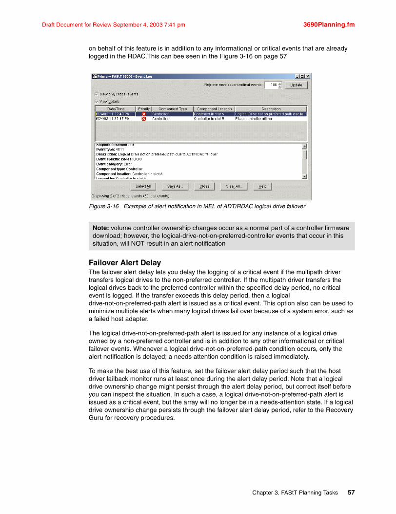
Draft Document for Review September 4, 2003 7:41 pm 3690Planning.fm
on behalf of this feature is in addition to any informational or critical events that are already logged in the RDAC.This can bee seen in the Figure 3-16 on page 57
Figure 3-16 Example of alert notification in MEL of ADT/RDAC logical drive failover
Failover Alert DelayThe failover alert delay lets you delay the logging of a critical event if the multipath driver transfers logical drives to the non-preferred controller. If the multipath driver transfers the logical drives back to the preferred controller within the specified delay period, no critical event is logged. If the transfer exceeds this delay period, then a logical drive-not-on-preferred-path alert is issued as a critical event. This option also can be used to minimize multiple alerts when many logical drives fail over because of a system error, such as a failed host adapter.
The logical drive-not-on-preferred-path alert is issued for any instance of a logical drive owned by a non-preferred controller and is in addition to any other informational or critical failover events. Whenever a logical drive-not-on-preferred-path condition occurs, only the alert notification is delayed; a needs attention condition is raised immediately.
To make the best use of this feature, set the failover alert delay period such that the host driver failback monitor runs at least once during the alert delay period. Note that a logical drive ownership change might persist through the alert delay period, but correct itself before you can inspect the situation. In such a case, a logical drive-not-on-preferred-path alert is issued as a critical event, but the array will no longer be in a needs-attention state. If a logical drive ownership change persists through the failover alert delay period, refer to the Recovery Guru for recovery procedures.
Note: volume controller ownership changes occur as a normal part of a controller firmware download; however, the logical-drive-not-on-preferred-controller events that occur in this situation, will NOT result in an alert notification
Chapter 3. FAStT Planning Tasks 57
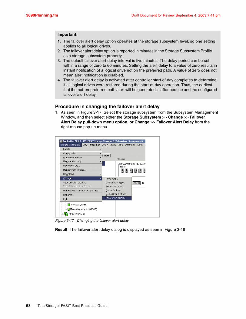
3690Planning.fm Draft Document for Review September 4, 2003 7:41 pm
Procedure in changing the failover alert delay1. As seen in Figure 3-17, Select the storage subsystem from the Subsystem Management
Window, and then select either the Storage Subsystem >> Change >> Failover Alert Delay pull-down menu option, or Change >> Failover Alert Delay from the right-mouse pop-up menu.
Figure 3-17 Changing the failover alert delay
Result: The failover alert delay dialog is displayed as seen in Figure 3-18
Important:
1. The failover alert delay option operates at the storage subsystem level, so one setting applies to all logical drives.
2. The failover alert delay option is reported in minutes in the Storage Subsystem Profile as a storage subsystem property.
3. The default failover alert delay interval is five minutes. The delay period can be set within a range of zero to 60 minutes. Setting the alert delay to a value of zero results in instant notification of a logical drive not on the preferred path. A value of zero does not mean alert notification is disabled.
4. The failover alert delay is activated after controller start-of-day completes to determine if all logical drives were restored during the start-of-day operation. Thus, the earliest that the not-on-preferred path alert will be generated is after boot up and the configured failover alert delay.
58 TotalStorage: FAStT Best Practices Guide

Draft Document for Review September 4, 2003 7:41 pm 3690Planning.fm
Figure 3-18 Changing the failover alert delay
2. Enter the desired delay interval in minutes and select OK.
Result: You are returned to the Subsystem Management Window.
Chapter 3. FAStT Planning Tasks 59

3690Planning.fm Draft Document for Review September 4, 2003 7:41 pm
60 TotalStorage: FAStT Best Practices Guide

Draft Document for Review September 4, 2003 7:41 pm 3690Implement.fm
Chapter 4. FAStT Implementation Tasks
This chapter recommends a sequence of tasks to setup, install and configure an IBM FAStT Storage Server. These include the following
1. Setting up the IP addresses on the IBM Storage Server2. Installing The FAStT Storage Manager Client3. Updating the BIOS and Firmware of the IBM Storage Server4. Initial setup of the IBM FAStT Storage Server5. Defining Logical Drives and hot-spares6. Setting up Storage Partitioning
4
© Copyright IBM Corp. 2003. All rights reserved. 61
3690Implement.fm Draft Document for Review September 4, 2003 7:41 pm
4.1 Preparing the FAStT Storage ServerThis chapter assumes that you have installed the operating system on the host server, and have all the nessessary device drivers and host software installed, and that you have a good understanding and working knowledge of the IBM FAStT Storage Server product. If you require detailed information on how to preform the installation and setup/configuration of this product, please refer to IBM TotalStorage FAStT600/900 and Storage Manager 8.4, SG24-7010-00 or consult the documentation for your operating system and host software.
4.1.1 Network setup of the controllersWith version 8.4 of the FAStT Storage Manager and the assigned firmware version of 5.2xxx for the controllers, the default behavior is to change an IP address.
By default, FAStT tries to use the bootstrap protocol (BOOTP) to request an IP address. If no BOOTP server can be contacted, the controllers fall back to the fixed IP addresses. These fixed addresses, by default, are:
� Controller A: 192.168.128.101� Controller B: 192.168.128.102
To use the network ports of the controllers, you need to attach both controllers to an Ethernet switch or hub. The built-in Ethernet controller supports either 100 Mbps or 10 Mbps.
To manage storage subsystems through a firewall, configure the firewall to open port 2463 for TCP data.
To change the default network setting (BOOTP with fallback to a fixed IP address), you need a serial connection to the controllers in the FAStT Storage Server.
1. Connect to the FAStT Storage Server with a null modem cable to the serial port of your system. For the serial connection, choose the correct port and the following settings:
– 19200 Baud– 8 Data Bits– 1 Stop Bit– No Parity– Xon/Xoff Flow Control
2. Send a break signal to the controller. This varies depending on the terminal emulation. For most terminal emulations, as HyperTerm, which is included in the Microsoft Windows products, press Ctrl+Break.
3. If you only receive unreadable characters, press Ctrl+Break again, until the following message appears:
Press <SPACE> for baud rate within 5 seconds.
4. Press the Space bar to ensure the correct baud rate setting. If the baud rate was set, a confirmation appears.
5. Press Ctrl+Break to log on to the controller. The following message appears:
Press within 5 seconds: <ESC> for SHELL, <BREAK> for baud rate.
Attention: Follow the procedure outlined here exactly as it is presented, because some commands that can be issued from the serial console can have destructive effects (causing loss of data or even affecting the functionality of your FAStT).
62 TotalStorage: FAStT Best Practices Guide
Draft Document for Review September 4, 2003 7:41 pm 3690Implement.fm
6. Press the Esc key to access the controller shell. The password you are prompted for is infiniti.
7. Run the netCfgShow command to see the current network configuration.
8. To change these values, enter the netCfgSet command. You are asked for each entry to keep, clear, or change the value. After you assign a fixed IP address to Controller A, disconnect from Controller A and repeat the procedure for Controller B. Remember to assign a different IP address.
9. Because the configuration changed, the network driver is reset and uses the new network configuration.
4.1.2 Installing and Starting the FAStT Storage Manager ClientYou can install the IBM FAStT Storage Manager Client (SMclient)for either in-band management, or out-of-band management. It is possible to use both on the same machine if you have a TCP/IP connection and also a Fibre Channel connection to the FAStT Storage Server
In-band management uses the Fibre Channel to communicate with the IBM FAStT Storage Server, while out-of-band management uses the TCPIP network to communicate with the IBM FAStT Storage Server. In our example we will use out-of-band management and install the Storage Manager Client on a machine that only has a TCP/IP connection to the FAStT Storage Server.
If you are unable to use a seperate network, ensure that you have an adequate password set on your FAStT Storage Server.
The are some advantages for doing this. First, it makes the storage more secure and limits the number of people that have access to the Storage Management functions. Second, it provides more flexibility as it eliminates the need for the storage administrator to access the server console for administration tasks. In addition, the Storage Manager agents and software do not take up resource on the host server.
Installing the SMclientTo install SMclient on Windows operating systems, perform the following steps:
1. Insert the IBM FAStT Storage Manager Version 8.4 CD into the CD-ROM drive.2. Click Start > Browse > %source_path%\displayed.exe to Run. The Run window opens.3. Follow the instructions presented through the install
Starting SMclientWhen you start the FAStT Storage Manager client, it launches the Enterprise Management window. The first time you start the client you are prompted to select whether you want an initial discovery of available storage subsystems (see Figure 4-1 on page 64).
Tip: For ease of management and security we recommend to install a management workstation on a seperate network.
Note: When you install FAStT SM client on a stand-alone host and manage storage subsystems through the Fibre Channel I/O path, rather than through the network, you must install the TCP/IP software on the host and assign an IP address to the host.
Chapter 4. FAStT Implementation Tasks 63

3690Implement.fm Draft Document for Review September 4, 2003 7:41 pm
Figure 4-1 Initial Automatic Discovery
The client software sends out broadcasts via Fibre Channel and the subnet of your IP network, if it finds directly attached storage subsystems or other hosts running the FAStT Storage Manager host agent with an attached storage subsystem.
You have to invoke the Automatic Discovery every time you add a new FAStT Storage Server in your network or install new host agents on already attached systems. To have them detected in your Enterprise Management window, click Tools > Rescan. Afterward all FAStT Storage Servers are listed in the Enterprise Management window as shown in Figure 4-2.
If you are connected via FC and TCP/IP you will see the same FAStT Storage Server twice.
Figure 4-2 The Enterprise Management window
The FAStT Storage Server may be connected via Ethernet, or you may want to manage through the host agent of another host, which is not in the same broadcast segment as your management station. In either case, you have to add the devices manually. Click Edit > Add device to enter the host name or the IP address you want to attach. If you add a FAStT Storage Server that is directly managed, be sure to enter both IP addresses – one per controller. Storage Manager will give you a warning message if you only assign an IP address to one controller.
By choosing the storage subsystem you want to manage, right-click and select Manage Device for the attached storage subsystem. This launches the Subsystem Management window (Figure 4-3).
Figure 4-3 First launch of the Subsystem Management window
64 TotalStorage: FAStT Best Practices Guide

Draft Document for Review September 4, 2003 7:41 pm 3690Implement.fm
Verify that the enclosures in the right half of the window reflect your actual physical layout. If the enclosures are listed in an incorrect order, select Storage Subsystem > Change > Enclosure Order and sort the enclosures according to your site setup
4.1.3 Updating the controller microcodeThe microcode of the FAStT Storage Server consists of two packages:
� The actual firmware.� The NVSRAM package, including the settings for booting the FAStT Storage Server
The NVSRAM is similar to the settings in the BIOS of a host system. The firmware and the NVSRAM are not independent. Be sure to install the correct combination of the two packages.
1. The upgrade procedure needs two independent connections to the FAStT Storage Server, one for each controller. It is not possible to perform a microcode update with only one controller connected. Therefore, both controllers must be accessible either via Fibre Channel or Ethernet. Both controllers must also be in the active state.
If you plan to upgrade via Fibre Channel, make sure that you have a multipath I/O driver installed on your management host, for example the FAStT RDAC package. This is necessary since the access logical drive moves from one controller to the other during this procedure and the FAStT Storage Server must be manageable during the entire time.
2. Open the Subsystem Management window for the FAStT Storage Server you want to upgrade. To download the firmware, follow these steps:
� Highlight the storage subsystem. From the Storage Subsystem menu, click Download > Firmware
You may also be asked to synchronize the clocks on the FAStT Storage Server with the host that you are using.
3. After you upgrade the firmware, you must also upgrade NVSRAM:
� Highlight the storage subsystem again and click Storage Subsystem > Download > NVSRAM
Since the NVSRAM is much smaller than the firmware package, it doesn’t take as long as the firmware download.
Important:
� Ensure that all hosts attached to FAStT have a multipath I/O driver installed.
� Any power or network/SAN interruption during the update process may lead to configuration corruption. Therefore, do not turn off the power to the FAStT Storage Server or the management station during the update. If you are using in-band management and have Fibre Channel hubs or managed hubs, then make sure any SAN connected devices are not powered up during the update. Otherwise, this can cause a loop initialization process (LIP) and interrupt the update process.
Note: If you applied any changes to the NVSRAM settings, for example running a script, you must re-apply them after the download of the new NVSRAM completes. The NVSRAM update resets all settings stored in the NVSRAM to their defaults.
Chapter 4. FAStT Implementation Tasks 65
3690Implement.fm Draft Document for Review September 4, 2003 7:41 pm
After the upgrade procedure, it is not necessary to power cycle FAStT. After the download, the controllers are rebooted automatically one by one and the FAStT Storage Server is online again.
If the FAStT Storage Server is not recognized or unresponsive after the upgrade in the Enterprise Management windows, remove the device from the Enterprise Management window and initiate a new discovery. If the FAStT Storage Server is still unresponsive, reboot the host system and initiate a discovery when the system is up again. This can be caused by the host agent not recognizing properly the updated FAStT.
4.2 Configuring the IBM TotalStorage FAStT Storage ServerBefore defining arrays or logical drives, you must perform some basic configuration steps. This also applies when you reset the configuration of your FAStT Storage Server.
1. If you install more than one FAStT Storage Server, it is important to give them a literal name. To name or rename the FAStT Storage Server, open the Subsystem Management window. Right-click the subsystem, and click Storage Subsystem > Rename
2. Since the FAStT Storage Server stores its own event log, synchronize the controller clocks with the time of the host system. If you have not already set the clocks on the Storage Servers, set them now. Be sure that your local system is working using the correct time. Then click Storage Subsystem > Set Controller Clock
3. For security reasons, especially if the FAStT Storage Server is directly attached to the network, you should set a password. This password is required for all actions on the FAStT Storage Server that change or update the configuration in any way.
To set a password, highlight the storage subsystem, right-click, and click Change > Password. This password is then stored on the FAStT Storage Server. It is used if you connect through another FAStT Client or the FAStT Field Tool. It does not matter whether you are using in-band or out-of-band management.
4.2.1 Defining hot-spare drivesHot-spare drives are special reserved drives that are normally not used to store data. But if a drive in a RAID array with redundancy, such as 1, 5 or 10, fails, the hot-spare drive takes on the function of the failed drive and the data is recovered on the hot-spare drives, which become part of the array. After this procedure, your data is again fully protected. Even if another drive fails, this cannot affect your data.
If the failed drive is replaced with a new drive, the data stored on the hot-spare drive is copied back to the replaced drive, and the original hot-spare drive that is now in use becomes a free hot-spare drive again. The location of a hot-spare drive is fixed and does not wander if it is used.
A hot-spare drive defined on the FAStT Storage Server is always used as a so-called global hot-spare. That is, a hot spare drive can always be used for a failed drive; it is not important in which array or storage enclosure it is situated.
Note: Make sure the time of the controllers and the attached systems are synchronized. This simplifies error determination when you start comparing the different event logs.
66 TotalStorage: FAStT Best Practices Guide

Draft Document for Review September 4, 2003 7:41 pm 3690Implement.fm
A hot-spare drive must be at least of the capacity of the configured space on the failed drive. the FAStT Storage Server can use a larger drive to recover a smaller failed drive to it. Then the remaining capacity is blocked.
If you plan to use several hot-spare drives, the FAStT Storage Server uses a certain algorithm to define which hot-spare drive is used. The controller first attempts to find a hot-spare drive on the same channel as the failed drive. The drive must be at least as large as the configured capacity of the failed drive. If a hot-spare drive does not exist on the same channel, or if it is already in use, the controller checks the remaining hot-spare drives, beginning with the last hot-spare configured. For example, the drive in enclosure 1, slot 4, may fail and the hot-spare drives may be configured in the following order:
� HSP 1: enclosure 0, slot 12� HSP 2: enclosure 2, slot 14� HSP 3: enclosure 4, slot 1� HSP 4: enclosure 3, slot 14
In this case, the controller checks the hot-spare drives in the following order:3:14 -> 4:1 -> 2:14 -> 0:12
The controller uses a free hot-spare drive as soon as it finds one, even if there is another one that may be closer to the failed drive.
To define a hot-spare drive, highlight the drive you want to use. From the Subsystem Management window click Drive > Hot Spare > Assign.
If there are larger drives defined in any array on the FAStT Storage Server than the drive you have chosen, a warning message appears and notifies you that not all arrays are protected by the hot-spare drive.
The new defined hot-spare drive then has a small red cross in the lower part of the drive icon.
Especially in large configurations with arrays containing numerous drives, we recommend the definition of multiple hot spare drives since the reconstruction of a failed drive to a hot spare drive can take a long time. See also Section 3.2.8, “Hot-spare drive” on page 47.
To unassign a hot-spare drive and have it available again as a free drive, highlight the hot-spare drive and select Drive > Hot Spare > Unassign
4.2.2 Creating arrays and logical drivesAt this stage, the storage subsystem has been installed and upgraded to the newest microcode level. Now, the arrays and logical drives can be configured. (If you are not sure how to divide the available drives into arrays or logical drives, and which restrictions apply, to avoid improper or inefficient configurations of the FAStT Storage Server, see IBM TotalStorage FAStT600/900 and Storage Manager 8.4, SG24-7010-00)
In the Subsystem Management window, right-click the unconfigured capacity and select Create Logical Drive.
� The Current default host type initally should be set, but will stick to the last type used from here on.
� You can select the check box to disable this dialog now. If you want to change Default Host Type later, click Storage Subsystem > Change > Default Host Type in the Subsystem Management window to access the window later.
4. The Create Logical Drive Wizard appears. It leads you through the creation of your logical drives. Choose the RAID level and number of drives that are used in the array, either by
Chapter 4. FAStT Implementation Tasks 67

3690Implement.fm Draft Document for Review September 4, 2003 7:41 pm
the manual option, or the automatic drive selection option. Unless you have specific needs to specifying the drives that are being used, choose automatic.
5. Define the logical drive. By default, all available space in the array is configured as one logical drive.
� Assign a name to the logical drive� If you want to change advanced logical drive settings as segment size or cache settings,
select the Customize settings option.
The newly created logical drive is not mapped automatically and remains unmapped. Otherwise, the drive is immediately seen by the attached hosts. If you change the mapping later, the logical drive, which appears as a physical drive to the operating system, is removed without notifying the hosts. This can cause severe problems.
6. On the Specify Advanced Logical Drive Parameters panel, you define the logical drive exactly to suit your needs:
� For Logical Drive I/O characteristics, you can specify file system, database, or multimedia base. Or you can manually set the parameters for the logical drive by choosing Custom.
� The segment size is chosen according to the usage pattern. For custom settings, you can directly define the segment size.
� You can also define the cache read-ahead multiplier. Begin by choosing only small values. Otherwise large parts of the cache are filled by read ahead data that may never be used.
� The preferred controller handles the logical drive normally if both controllers and I/O paths are online. You can load balance your logical drives throughout both controllers. The default is to alternate the logical drives on the two controllers.
� You can choose to set the Logical Drive to LUN mapping parameter to run automatically or to be delayed by mapping it later with storage partitioning. If you choose to map later to the default host group, keep in mind that the logical drive becomes visible immediately after the creation. The recommendation is to never leave LUNs in the default group.
If the logical drive is smaller than the total capacity of the array, a window opens and asks whether you want to define another logical drive on the array. The alternative is to leave the space as unconfigured capacity. After you define all logical drives on the array, the array is now initialized and immediately accessible.
If you left unconfigured capacity inside the array, you can define another logical drive later in this array. Simply highlight this capacity, right-click, and choose Create Logical Drive. Simply follow the steps that we outlined in this section, except for the selection of drives and RAID level. Since you now already defined arrays that contain free capacity, you can choose where to store the new logical drive – on an existing array or on a new one.
4.2.3 Configuring storage partitioningWith storage partitioning, heterogeneous hosts can be attached to the FAStT Storage Server; you then need to configure storage partitioning for two reasons:
� Each host operating system requires slightly different settings on the FAStT Storage Server, so you need to tell the storage subsystem the host type that is attached.
� There is interference between the hosts if every host has access to every logical drive. By using storage partitioning and LUN masking, you ensure that each host or host group only has access to its assigned logical drives.
To configure storage partitioning, follow these steps:
1. Choose the Mappings View in the Subsystem Management window.
68 TotalStorage: FAStT Best Practices Guide

Draft Document for Review September 4, 2003 7:41 pm 3690Implement.fm
2. All information, such as host ports and logical drive mappings, are shown and configured here. The right side of the window lists all mappings that are owned by the object you choose in the left side. If you highlight the storage subsystem, you see a list of all defined mappings. If you highlight a specific host group or host only, its mappings are listed.
3. Define the host groups. Highlight the Default Group, right-click, and choose Define Host Group.
4. The hosts groups are defined and the hosts in these groups can now be defined. Highlight the group for which you want to add a new host. Right-click and choose Define Host and enter your desired host name. It is a good idea to make the host name something that is descriptive to the host that it represents.
If you accidentally assigned a host to the wrong host group, you can move the host to another group. Simply right-click the host name and select Move. A pop-up window opens and asks you to specify the host group name.
5. Because storage partitioning of the FAStT Storage Server is based on the world-wide names of the host ports, the definitions for the host groups and the hosts only represent a view of the physical and logical setup of your fabric. When this structure is available, it is much easier to identify which host ports are allowed to see the same logical drives and which are in different storage partitions.
Storage partitioning is not the only function of the storage server that uses the definition of the host port. When you define the host ports, the operating system of the attached host is defined as well. Through this information, FAStT can adapt the RDAC or ADT settings for the hosts.
It is important to choose the correct operating system from the list of available operating systems, because this is the part of the configuration where you configure the heterogeneous host support. Each operating system expects slightly different settings and handles SCSI commands a little differently. Therefore, it is important to select the correct value. If you don’t, your operating system may not boot anymore or path failover cannot be used if connected to the storage subsystem.
The host port is identified by the world-wide name of the host bus adapter. Highlight the host, right-click, and choose Define Host Port. In the Define Host Port dialog enter the port name for this adapter and choose the correct operating system. The host port identifier corresponds to the world-wide name of the adapter port. In the drop-down box, you only see the world-wide names that are currently active. If you want to enter a host port that is not currently active, type the world-wide name in the field. Be sure to check for typing errors.
6. Define the mapping for each logical drives that have been created. All the information entered on the Define Host Port dialog is needed to ensure a proper operation in a heterogeneous environment with multiple servers attached to the FAStT Storage Server.
Highlight the host group to which you want to map a new logical drive. Right-click and choose Define Additional Mapping.
7. In the Define Additional Mapping dialog, select the logical drive you want to map to this host group and assign the correct LUN number.
Note: If only one server will access the logical disks in a storage partition, then it is not necessary to define a host group because you could use the default host group. However, as requirements are constantly changing, we recommend that you define a host group anyway. Otherwise the addition of new systems is not possible without disrupting the mappings already defined in the default host group.
Chapter 4. FAStT Implementation Tasks 69

3690Implement.fm Draft Document for Review September 4, 2003 7:41 pm
a. In the top drop-down list, you can choose the host group or host to which you want to map the logical drive.
b. With the logical unit number, you can influence the order in which the mapped logical drives appear. Starting with LUN 0, the logical drive appears in the operating system.
c. In the list box that follows, you see all unmapped drives. Choose the logical drive you want to map.
If you entered all the information, click Add to finish defining this mapping. The first mapping is now defined. In the Subsystem Management window, you see that the number of used storage partitions changed from 0/64 to 1/64.
You can define all other mappings by repeating these steps. You receive an error message after the last logical drive is mapped to a host group or host.
If you have a single server in a host group that has one or more LUN assigned to it, it is recommended to assign the mapping to the host and not the host group. All servers having the same host type, for example all Windows NT servers, can be in the same group if you want, but, by mapping at the host level you can define what specific server accesses what specific LUN.
If you have a cluster, it is good practice to assign the LUNS to the host group, so that all of the servers in the host group have access to the LUNs.
Now all logical drives and their mappings are defined and are now accessible by their mapped host systems.
To make the logical drives available to the host systems without rebooting, the FAStT Utilities package provides the hot_add command line tool for some operating systems. You simply run hot_add, and all host bus adapters are re-scanned for new devices and the devices are assigned within the operating system. Linux now requires a new configuration done with the FAStT MSJ. Refer to IBM TotalStorage FAStT600/900 and Storage Manager 8.4, SG24-7010-00 for step by step instructions for this procedure.
You may have to take appropriate steps to enable the use of the storage inside the operating system, such as formatting the disks with a file system and mount them.
If you attached a Linux or AIX system to the FAStT Storage Server, you need to delete the mapping of the access LUN. Highlight the host or host group containing the Linux or AIX system in the Mappings View. In the right part of the window, you see the list of all logical drives mapped to this host or host group. To delete the mapping of the access logical drive, right-click it and choose Delete. The mapping of the access logical drive is deleted immediately.
Note: If you create a new mapping or change an existing mapping of a logical drive, the change happens immediately. Therefore, make sure that this logical drive is not in use or even assigned by any of the machines attached to the storage subsystem.
70 TotalStorage: FAStT Best Practices Guide

Draft Document for Review September 4, 2003 7:41 pm 3690Maint.fm
Chapter 5. FAStT Maintenance
This chapter describes various maintenance functions of the FASt, such as performance monitoring, error reporting and alerts. It also covers how to use performance monitor data to make decisions regarding the tuning of the storage subsystem
5
© Copyright IBM Corp. 2003. All rights reserved. 71
3690Maint.fm Draft Document for Review September 4, 2003 7:41 pm
5.1 Performance monitoring and tuningThis section describes the performance monitor and how the data it provides can be used to tune various parameters. It also looks at what settings can be adjusted and what results to expect.
5.1.1 The performance monitorUse the performance monitor option to select logical drives and controllers to monitor or to change the polling interval.
To change the polling interval, choose a number of seconds in the spin box. Each time the polling interval elapses, the performance monitor re-queries the storage subsystem and updates the statistics in the table.
If you are monitoring the storage subsystem in real time, update the statistics frequently by selecting a short polling interval, for example, five seconds.
If you are saving results to a file to look at later, choose a slightly longer interval, for example, 30 to 60 seconds, to decrease the system overhead and the performance impact.
The performance monitor will not dynamically update its display if any configuration changes (for example, creation of new logical drives, change in logical drive ownership, and so on) occur while the monitor window is open. The Performance Monitor window MUST be closed and then reopened for the changes to appear.
Using the performance monitor to collect performance data can affect the normal storage subsystem performance depending on the polling interval that you set.
If the storage subsystem you are monitoring begins in or transitions to an unresponsive state, an informational dialog is displayed, stating that the performance monitor cannot poll the storage subsystem for performance data.
Use the performance monitor data to make storage subsystem tuning decisions as described below:
Total I/OsThis data is useful for monitoring the I/O activity of a specific controller and a specific logical drive, which can help identify possible high-traffic I/O areas.
If I/O rate is slow on a logical drive, try increasing the array size.
You might notice a disparity in the Total I/Os (workload) of controllers, for example, the workload of one controller is heavy or is increasing over time while that of the other controller is lighter or more stable. In this case, consider changing the controller ownership of one or more logical drives to the controller with the lighter workload. Use the logical drive Total I/O statistics to determine which logical drives to move.
If you notice the workload across the storage subsystem (Storage Subsystem Totals Total I/O statistic) continues to increase over time while application performance decreases, this might
Tip: There is no golden rule of thumb for storage performance optimization that is valid in every environment and for every specific situation. The best way to understand disk I/O and throughput requirements is to monitor an existing system.
72 TotalStorage: FAStT Best Practices Guide

Draft Document for Review September 4, 2003 7:41 pm 3690Maint.fm
indicate the need to add additional storage subsystems to your installation so that you can continue to meet application needs at an acceptable performance level.
Read percentageUse the read percentage for a logical drive to determine actual application behavior. If there is a low percentage of read activity relative to write activity, consider changing the RAID level of an array from RAID 5 to RAID 1 for faster performance.
Cache hit percentageA higher percentage is desirable for optimal application performance. There is a positive correlation between the cache hit percentage and I/O rates.
The cache hit percentage of all of the logical drives may be low or trending downward. This may indicate inherent randomness in access patterns, or, at the storage subsystem or controller level, this can indicate the need to install more controller cache memory if you do not have the maximum amount of memory installed.
If an individual logical drive is experiencing a low cache hit percentage, consider enabling cache read ahead for that logical drive. Cache read ahead can increase the cache hit percentage for a sequential I/O workload.
Determining the effectiveness of a logical drive cache read ahead multiplierTo determine if your I/O has sequential characteristics, try enabling a conservative cache read-ahead multiplier (four, for example). Then, examine the logical drive cache hit percentage to see if it has improved. If it has, indicating that your I/O has a sequential pattern, enable a more aggressive cache read-ahead multiplier (eight, for example). Continue to customize logical drive cache read-ahead to arrive at the optimal multiplier (in the case of a random I/O pattern, the optimal multiplier is zero).
Current KB/sec and maximum KB/secThe transfer rates of the controller are determined by the application I/O size and the I/O rate. Generally, small application I/O requests result in a lower transfer rate but provide a faster I/O rate and shorter response time. With larger application I/O requests, higher throughput rates are possible. Understanding your typical application I/O patterns can help you determine the maximum I/O transfer rates for a given storage subsystem.
Consider a storage subsystem, equipped with Fibre Channel controllers, that supports a maximum transfer rate of 100 MB/second (100,000 KB per second). Your storage subsystem typically achieves an average transfer rate of 20,000 KB/second. (The typical I/O size for your applications is 4K, with 5,000 I/Os transferred per second for an average rate of 20,000 KB/second). In this case, I/O size is small. Because there is system overhead associated with each I/O, the transfer rates will not approach 100,000 KB per second. However, if your typical I/O size is large, a transfer rate within a range of 80,000 to 90,000 KB per second might be achieved.
Current I/O per sec and maximum I/O per secFactors that affect I/Os per second include access pattern (random or sequential), I/O size, RAID level, segment size, and number of drives in the arrays or storage subsystem. The higher the cache hit rate, the higher I/O rates will be.
Performance improvements caused by changing the segment size can be seen in the I/Os per second statistics for a logical drive. Experiment to determine the optimal segment size, or use the file system or database block size.
Chapter 5. FAStT Maintenance 73
3690Maint.fm Draft Document for Review September 4, 2003 7:41 pm
Higher write I/O rates are experienced with write caching enabled compared to disabled. In deciding whether to enable write caching for an individual logical drive, consider the current and maximum I/Os per second. You should expect to see higher rates for sequential I/O patterns than for random I/O patterns. Regardless of your I/O pattern, it is recommended that write caching be enabled to maximize I/O rate and shorten application response time.
5.1.2 Tuning cache parametersPlease refer to Section 3.2.7, “Cache parameters” on page 43
5.2 Controlling the performance impact of maintenance tasksFrom time to time you need to run maintenance or performance tuning operations or you may have a requirement to run VolumeCopy or Remote Volume Mirroring operations.
All of these operations are considered business as usual, but will however affect the system performance. They run as background tasks, controlled by the storage subsystem firmware. The storage subsystem controls the sharing of resources between the background task and host systems I/O activity.
To help you control the impact of background tasks, the system allows you to set the priority of the background tasks. This setting effectively adjusts the ratio of resources that are allocated between the host system I/O and the background operations.
This becomes a trade-off between having the background operation complete in the fastest possible time and potentially impact host system performance or having minimal impact on the host system performance but taking more time to complete the background task.
These background tasks can be categorized as follows:
5.2.1 Modification operationsA modification operation is a controller-based operation, where the controller is required to write and, in some cases, rewrite data to arrays, logical drives, and disk drives.
The modification priority defines how much processing time is allocated for logical drive modification operations relative to system performance. To learn more about setting the modification priority, refer to the IBM TotalStorage FAStT600/900 and Storage Manager 8.4, SG24-7010-00
Modification operations include:
• Defragment an array
A fragmented array can result from logical drive deletion or from not using all available free capacity in a Free Capacity node during logical drive creation.
Because new logical drives cannot spread across several free space nodes, the logical drive size is limited to the greatest free space node available, even if there is more free space in the logical drive. The array needs to be defragmented first to consolidate all free space nodes to one free space node for the array. Then a new logical drives can use the whole available free space.
Use the defragment option to consolidate all free capacity on a selected array. The defragmentation runs concurrently with normal I/O; it impacts performance because data of the logical drives must be moved within the array. Depending on the array configuration, this process continues to run for a long period of time. Once the
74 TotalStorage: FAStT Best Practices Guide

Draft Document for Review September 4, 2003 7:41 pm 3690Maint.fm
procedure is started, it cannot be stopped again. During this time, no configuration changes can be performed on the array.
The defragmentation done on the FAStT Storage Server only applies to the free space nodes on the array. It is not connected to a defragmentation of the file system used by the host operating systems in any way.
• Copyback
Copyback refers to the process of copying data from a hot-spare drive ((used as a standby, in case of possible drive failure) to a replacement drive. When you have physically replaced the failed drive, a copyback operation automatically occurs from the hot-spare drive to the replacement drive.
• Initialization
The deletion of all data on a drive, logical drive, or array. In previous versions of the storage management software, this was called format.
• Dynamic Segment Sizing (DSS)
Dynamic Segment Sizing (DSS) describes a modification operation where the segment size for a select logical drive is changed to increase or decrease the number of data blocks that the segment size contains. A segment is the amount of data that the controller writes on a single drive in a logical drive before writing data on the next drive.
• Dynamic Reconstruction Rate (DRR)
Dynamic Reconstruction Rate (DRR) is a modification operation where data and parity within an array are used to regenerate the data to a replacement drive or a hot spare drive. Only data on a RAID 1, 3, or 5 logical drive can be reconstructed.
• Dynamic RAID Level Migration (DRM)
Dynamic RAID Level Migration (DRM) describes a modification operation used to change the RAID level on a selected array. The RAID level selected determines the level of performance and parity of an array.
• Dynamic Capacity Expansion (DCE)
Dynamic Capacity Expansion (DCE) describes a modification operation used to increase the available free capacity on an array. The increase in capacity is achieved by selecting unassigned drives to be added to the array. Once the capacity expansion is completed, additional free capacity is available on the array for creation of other logical drives. The additional free capacity can then be used to perform a Dynamic Logical Drive Expansion (DVE) on a standard or FlashCopy repository logical drive.
• Dynamic Logical Drive Expansion (DVE)
Dynamic Logical Drive Expansion (DVE) is a modification operation used to increase the capacity of a standard logical drive or a FlashCopy repository logical drive. The increase in capacity is achieved by using the free capacity available on the array of the standard or FlashCopy repository logical drive.
The modification priority rates are lowest, low, medium, high, highest.
Note: The lowest priority rate favors system performance, but the modification operation takes longer. The highest priority rate favors the modification operation, but system performance may be compromised.
Chapter 5. FAStT Maintenance 75

3690Maint.fm Draft Document for Review September 4, 2003 7:41 pm
5.2.2 Remote Volume Mirroring OperationsWhen a storage subsystem logical drive is a primary logical drive and a full synchronization is necessary, the controller owner performs the full synchronization in the background while processing local I/O writes to the primary logical drive and associated remote writes to the secondary logical drive. Because the full synchronization diverts controller processing resources from I/O activity, it can impact performance on the host application. The synchronization priority defines how much processing time is allocated for synchronization activities relative to system performance.
The synchronization priority rates are lowest, low, medium, high, highest.
The following guidelines roughly approximate the differences between the five priorities. Logical drive size and host I/O rate loads affect the synchronization time comparisons:
� A full synchronization at the lowest synchronization priority rate takes approximately eight times as long as a full synchronization at the highest synchronization priority rate.
� A full synchronization at the low synchronization priority rate takes approximately six times as long as a full synchronization at the highest synchronization priority rate.
� A full synchronization at the medium synchronization priority rate takes approximately three and a half times as long as a full synchronization at the highest synchronization priority rate.
� A full synchronization at the high synchronization priority rate takes approximately twice as long as a full synchronization at the highest synchronization priority rate.
� The synchronization progress bar at the bottom of the Mirroring tab of the Logical Drive Properties dialog displays the progress of a full synchronization.
5.2.3 VolumeCopy priority ratesSeveral factors contribute to system performance, including I/O activity, logical drive RAID level, logical drive configuration (number of drives in the array or cache parameters), and logical drive type (FlashCopy logical drives may take more time to copy than standard logical drives).
You can select the copy priority while you are creating a new logical drive copy, or you can change it later using the Copy Manager. The copy priority rates are lowest, low, medium, high, highest.
5.2.4 FlashCopy operationsIf you no longer need a FlashCopy logical drive, you may want to disable it. As long as a FlashCopy logical drive is enabled, your storage subsystem performance is impacted by the copy-on-write activity to the associated FlashCopy repository logical drive. When you disable a FlashCopy logical drive, the copy-on-write activity stops.
Note: The lowest priority rate favors system performance, but the full synchronization takes longer. The highest priority rate favors full synchronization, but system performance may be compromised.
Note: The Lowest priority rate supports I/O activity, but the logical drive copy will take longer. The Highest priority rate supports the logical drive copy, but I/O activity may be affected.
76 TotalStorage: FAStT Best Practices Guide
Draft Document for Review September 4, 2003 7:41 pm 3690Maint.fm
If you disable the FlashCopy logical drive instead of deleting it, you can retain it and its associated repository. Then, when you need to create a different FlashCopy of the same base logical drive, you can use the re-create option to reuse a disabled FlashCopy. This takes less time.
5.3 Event monitoring and alertsIncluded in the FAStT Client package is the Event Monitor service. It enables the host running this monitor to send out alerts via e-mail (SMTP) or traps (SNMP). The Event Monitor can be used to alert problems with any of the FAStT Storage Servers in your environment.
Depending on the setup you choose, different storage subsystems are monitored by the Event Monitor. If you right-click your local system in the Enterprise Management window (at the top of the tree) and choose Alert Destinations, this applies to all storage subsystems listed in the Enterprise Management window. Also if you see the same storage subsystem through different paths, directly attached and through different hosts running the host agent, you receive multiple alerts. If you right-click a specific storage subsystem, you only define the alerting for this particular FAStT Storage Server.
An icon in the lower left corner of the Enterprise Management window indicates that the Event Monitor is running on this host.
If you want to send e-mail alerts, you have to define an SMTP server first. Click Edit > Configure Mail Server. Enter the IP address or the name of your mail server and the sender address.
If you open the Alert Destination dialog, you define the e-mail addresses to which alerts are sent. If you do not define an address, no SMTP alerts are sent. You also can validate the e-mail addresses to ensure a correct delivery and test your setup.
If you choose the SNMP tab, you can define the settings for SNMP alerts: the IP address of your SNMP console and the community name. As with the e-mail addresses, you can define several trap destinations.
You need an SNMP console for receiving and handling the traps sent by the service. There is an MIB file included in the Storage Manager software, which should be compiled into the SNMP console to allow proper display of the traps. Refer to the documentation of the SNMP console you are using to learn how to compile a new MIB.
5.3.1 IBM FASt Service AlertFAStT Service Alert is a feature of the IBM TotalStorage FAStT Storage Manager that monitors system health and automatically notifies the IBM Support Center when problems occur. Service Alert sends an e-mail to a call management center that identifies your system and captures any error information that can identify the problem. The IBM support center analyzes the contents of the e-mail alert and contacts you with the appropriate service action.
Service offering contractFollowing is an overview of the process for obtaining a service offering contract:
Tip: The Event Monitor service should be installed and configured on at least two systems that are attached to the storage subsystem and allow in-band management, running 24 hours a day. This practice ensures proper alerting, even if one server is down.
Chapter 5. FAStT Maintenance 77
3690Maint.fm Draft Document for Review September 4, 2003 7:41 pm
� The account team submits an RPQ requesting Service Alert, using the designated country process.
� The TotalStorage Hub receives the request and ensures that the following prerequisites are met: – The machine type, model, and serial number are provided. – The FAStT Storage Server management station is running Storage Manager client
version 8.3. – The FAStT Storage Server firmware level is at 05.3x.xx.xx or 04.01.xx.xx. – The FAStT Storage Server management station has Internet access and e-mail
capability. – Willingness to sign the contract with the annual fee.
� After the prerequisites are confirmed, the service offering contract is sent. � When the contract has been signed, the approval is sent from the TotalStorage Hub, with
the support team copied. � Billing is sent at the start of the contract.
Activating FAStT Service AlertTo activate Service Alert, you must do the following tasks:
� Create a user profile (userdata.txt) � Rename each storage subsystem and synchronize the controller clock � Configure the e-mail server � Configure the alert destination � Validate the installation � Test the system
PrerequisitesBefore you use Service Alert, you must install Storage Manager Client version 8.3 in the FAStT Storage Server management station. In addition, the FAStT Storage Server firmware levels must be at 05.3x.xx.xx or 04.01.xx.xx.
� If your FAStT Storage Server is running with firmware versions 05.0, 05.20, or 05.21, you must download Storage Manager Client 8.3 and firmware version 05.3x.xx.xx. This storage manager client and firmware upgrade is provided at no charge. For upgrading Storage manager firmware refer to Section 4.1.3, “Updating the controller microcode” on page 65
Creating a user profileThe user profile (userdata.txt) is a text file that contains your individual contact information. It is placed at the top of the e-mail that Service Alert generates. A template is provided, which you can download and edit using any text editor.
Perform the following steps to create the user profile:
1. Download the userdata.txt template file from one of the following Web sites:
http://www.ibm.com/storage/fastX00
where X00 represents the appropriate FAStT model (200, 500, 700 0r 900)
The userdata.txt template is named "userdata.txt".
Important: The user profile file name must be userdata.txt. The file content must be in the format as described in step 2. In addition, the file must be placed in the appropriate directory in the FAStT Storage Server management station as indicated in step 4
78 TotalStorage: FAStT Best Practices Guide

Draft Document for Review September 4, 2003 7:41 pm 3690Maint.fm
2. Type in the required information. There should be seven lines of information in the file. The first line should always be "Title: IBM FAStT Product". The other lines contain the company name, company address, contact name, contact phone number, alternate phone number, and machine location information. Do not split the information for a given item; for example, do not put the company address on multiple lines. Use only one line for each item.
The Title field of the userdata.txt file must always be "IBM FAStT Product". The rest of the fields should be completed for your specific FAStT Storage Server installation.
Following is an example of a completed userdata.txt user profile:
Example 5-1 Sample userdata.txt
Title: IBM FAStT Product Company name: IBM (73HA Department) Address: 3039 Cornwallis Road, RTP, NC 27709 Contact name: John Doe Contact phone number: 919-254-0000 Alternate phone number: 919-254-0001 Machine location: Building 205 Lab, 1300
3. Save the userdata.txt file in ASCII format.
4. Store the userdata.txt file in the appropriate subdirectory of the FAStT Storage Server management station, depending on the operating system that is installed in the management station:
� For Microsoft Windows 2000 and Windows NT4, store the userdata.txt file in the %SystemRoot%\java\ directory if Event Monitor is installed, or, if Event Monitor is not installed, in the Installed_Windows_driveletter:\Documents and Settings\Current_login_user_folder directory.
� If your Windows 2000 or Windows NT4 installation uses the default installation settings, and the current login user ID is Administrator, the directories are c:\WINNT\java or c:\Documents and Settings\Administrator respectively.
� For AIX, store the userdata.txt file in the / directory.
� For Red Hat Advanced Server, store the userdata.txt file in the default login directory of the root user. In normal installation, this directory is /root.
� For SuSE 8, store the userdata.txt file in the default login directory of the root user. In normal installation, this directory is /root.
� For Novell NetWare, store the userdata.txt file in the sys:/ directory.
� For Solaris, store the userdata.txt file in the / directory.
� For HP-UX, store the userdata.txt file in the / directory.
� VMware ESX servers that are connected to a FAStT Storage Server will require a separate workstation for FAStT Storage Server management. Service Alert is only
Note: When you type in the text for the userdata.txt file, the colon (:) is the only legal separator between the required label and the data. No extraneous data is allowed (blanks, commas, and so on) in the label unless specified. Labels are not case sensitive.
Note: You must have a Storage Manager client session running to monitor failures of the FAStT Storage Server.
Chapter 5. FAStT Maintenance 79

3690Maint.fm Draft Document for Review September 4, 2003 7:41 pm
supported in a VMware ESX and FAStT environment by way of the remote management station.
Renaming the FAStT subsystem and synchronizing the controller clockWhen you register for Service Alert, you must change the existing node ID of each FAStT Storage Server. Service Alert uses this new name to identify which FAStT Storage Server has generated the problem e-mail. To rename the Storage Server refer to Section 4.1.2, “Installing and Starting the FAStT Storage Manager Client” on page 63. Before you rename the storage subsystem, record the FAStT Storage Server machine type, model, and serial number.
Type the new name for the subsystem. You must use the following naming convention for the new name; any errors in the format of the new name can result in delays or denial of IBM service support. The new name cannot contain more than 30 characters. The format for the new name is:
ttttmmm/sssssss#cust_nodeid_reference
Where:
– tttt is the 4-digit IBM machine type of the product– mmm is the 3-digit IBM model number for the product– / is the required separator– sssssss is the 7-digit IBM serial number for the machine– # is the required separator– cust_nodeid_reference is the node ID as referenced by the customer
Use the information provided in Table 5-1i as reference list of FAStT machine types and model numbers.
Table 5-1 FAStT Storage Server Machine and Model Numbers
Following are some examples of a storage subsystem names:
1742900/23A1234#IBM_Eng 1742000/23A1235#IBM_Acctg 3552000/23A1236#IBM_Mktg 3542000/23A1237#IBM_Mfg
5. Click OK to save the new name.
6. To synchronize the controller clock with the time in the FAStT Storage Server management station that monitors the alerts, refer to Section 4.1.2, “Installing and Starting the FAStT Storage Manager Client” on page 63
Important: No extra characters are allowed before the "#" separator.
Product Machine Type Model Number Model Number in your name
FAStT900 1742 90U, 90X 900
FAStT700 1742 1RU, 1RX 000
FAStT500 3552 1RU, 1RX 000
FAStT200 3542 1RU, 1RX2RU, 2RX
000
80 TotalStorage: FAStT Best Practices Guide

Draft Document for Review September 4, 2003 7:41 pm 3690Maint.fm
This step is optional. If performed, it facilitates the trouble- shooting session because the time that the alert e-mail is sent is about the same as the time that the errors occurred in the FAStT Storage Server.
Steps 1 - 6 must be performed for each of the FAStT Storage Servers that support Service Alert.
Configuring the e-mail serverYou must configure your e-mail server to enable it to send alerts. Refer to Section 5.3, “Event monitoring and alerts” on page 77 for instructions on how to do this
The email address you enter will be used to send every alert that is sent
Configuring the alert destinationRefer to Section 5.3, “Event monitoring and alerts” on page 77 for instructions on how to do this
In the E-mail address: text box, type either one of the following e-mail addresses, depending on your geographic location:
� For EMEA and A/P locations: [email protected]� For North America locations: [email protected]� For South and Central America, and Caribbean Island locations: [email protected]
Validating the Service Alert installationMake sure that the IBM FAStT Event Monitor service is installed in the management station. If it is not installed, you must uninstall the FAStT Storage Manager client and reinstall it with the Event Monitor service enabled.
Testing the Service Alert installationAfter all previous tasks have been completed, you are ready to test your system for Service Alert.
Call your IBM Support Center. Tell the representative that you are ready to test the Service Alert process. The IBM representative will work with you to test your system setup and ensure that FAStT Service Alert is working properly.
A test that you will perform, with the help of the Support Center, is to manually fail a non-configured drive in the FAStT Storage Server using the FAStT Storage Manager client. If all of the drives are configured, you can turn off a redundant power supply in the FAStT Storage Server or FAStT expansion enclosure. When the drive fails or the power supply is turned off, a Service Alert is sent to the IBM e-mail address that you specified in “Configuring the e-mail server” on page 81
Note: FAStT Event Monitor service is not supported on Novell Netware 6. You must use a management station with other operating systems installed, such as Windows 2000
Note: Do not turn off the power supply if this is the only one that is powered on in your storage server or expansion enclosure. Turning off the power supply is the preferred test because it allows the testing of the FAStT Storage Server Event Monitor service. This service monitors the FAStT Storage Server for alerts without needing to have the FAStT Storage Manager client running in the root user session
Chapter 5. FAStT Maintenance 81

3690Maint.fm Draft Document for Review September 4, 2003 7:41 pm
5.4 Saving the subsystem profileConfiguring a FAStT Storage Server is a complex task. Therefore, the so-called subsystem profile is a single location where all the information on the configuration is stored. The profile includes information on the controllers, attached drives and enclosures, their microcode levels, arrays, logical drives, and storage partitioning.
To obtain the profile, open the Subsystem Management window and click View > Storage Subsystem Profile.
5.5 Upgrades and MaintenanceEvery so often IBM will release new firmware (it is posted on the support the website), that will need to be installed.
This section reviews the required steps to upgrade your IBM TotalStorage FAStT Storage Server when firmware updates and/or fixes become available. Upgrades must be preformed completely, which means if you upgrade the FAStT Storage Server firmware, you must also upgrade the device drivers, RDAC and utilities and SM Client to the same version.
It is possible to manage a FAStT Storage Server running downlevel firmware with the latest SMclient but not to manage a Storage Server running the latest version of firmware with a down level client.
5.5.1 Prerequisites for upgradesUpgrading the firmware and management software for the FAStT Storage Server is a relatively simple procedure. Before you start you should make sure that you have an adequate maintenance window to do the procedure as on large configurations it can be a little time consuming. The times for upgrading All the associated firmware and software are in Table 5-2. These times are only an approximate time and may vary from system to system.
Table 5-2 Upgrade Times
It is critical that if you update one part of the firmware/software, you update all the firmware/software to the same level. You must NOT run a miss-matched set.
All the nessessary files for doing this upgrade can be found at the following URL
http://www-3.ibm.com/pc/support/site.wss/document.do?lndocid=MIGR-4JTS2T
Tip: You should save a new profile each time you change the configuration of the FAStT storage subsystem even for minor changes. This applies to all changes regardless of how minor they may be. The profile should be stored in a location where it is available even after a complete configuration loss, for example after a site loss.
Element being upgraded Approximate time of upgrade
Storage Manager Software and associated drivers and software
35 Minutes
FAStT Storage Server Firmware 5 Minutes
FAStT ESM Firmware 5 Minutes
Hard Drives 3 Minutes per drive
82 TotalStorage: FAStT Best Practices Guide

Draft Document for Review September 4, 2003 7:41 pm 3690Maint.fm
5.5.2 Updating FAStT host software
Updating for the Windows environment1. Uninstall the storage management components in the following order:
a. SMagentb. SMutilc. RDACd. SMclient
2. Verify that the IBM host adapter device driver versions are current. If they are not current, refer to the readme file located with the device driver and then upgrade the device drivers
3. Install the storage manager components in the following order
a. RDACb. SMagentc. SMutild. SMclient
Updating for the Linux environment1. Uninstall the storage manager components in the following order
� FAStT Runtime environment� SMutil� SMclient
2. Verify that the IBM host adapter device driver versions are current. If they are not current refer to the readme file located with the device driver and then upgrade the device drivers.
3. Install the storage manager components in the following order
a. FAStT Runtime environmentb. SMutilc. SMclient
5.5.3 Updating microcodeUpdating the firmware of your FAStT Storage server will be required from time to time to keep up with the latest fixes and enhancements. For full instructions on how this is done you should refer to the documentation that is supplied with the firmware.
You should update the microcode in the following order
1. Controller firmware/NVSRAM2. ESM firmware3. Hard Drive firmware
Chapter 5. FAStT Maintenance 83

3690Maint.fm Draft Document for Review September 4, 2003 7:41 pm
84 TotalStorage: FAStT Best Practices Guide
Draft Document for Review September 4, 2003 7:41 pm 3690HACMP.fm
Chapter 6. FAStT and HACMP
In this chapter we present and discuss configuration information relevant to the FAStT Storage Server attached to IBM pSeries with High Availability Cluster Multi Processing (HACMP) installed under AIX.
HACMP is IBM’s software for building highly available clusters on IBM Scalable POWER (SP) Parallel systems and/or a combination of pSeries systems. It is supported by a wide range of IBM pSeries systems, with the new storage systems, and network types and it is one of the highest-rated UNIX-based clustering solutions in the industry.
6
© Copyright IBM Corp. 2003. All rights reserved. 85
3690HACMP.fm Draft Document for Review September 4, 2003 7:41 pm
6.1 HACMP introductionClustering (of servers) is the linking of two or more computers or nodes into a single, unified resource. High availability clusters are designed to provide continuous access to business-critical data and applications through component redundancy and application failover. HACMP links IBM pSeries servers or logical partitions (LPARs) of pSeries servers into high availability clusters. These servers or LPARs can also be part of an IBM Cluster 1600, which can simplify multisystem management and help reduce the cost of ownership.
HACMP provides concurrent access to IT resources and the fault resilience required for business-critical applications. It is designed to automatically detect system or network failures and eliminate a single point-of-failure by managing failover to a recovery processor with a minimal loss of end-user time.
The current release of HACMP can detect and react to software failures severe enough to cause a system crash and network or adapter failures. The Enhanced Scalability capabilities of HACMP offer additional availability benefits through the use of the Reliable Scalable Cluster Technology (RSCT) function of AIX. The Concurrent Resource Manager of HACMP provides concurrent access to shared disks in a highly available cluster, allowing tailored actions to be taken during takeover to suit business needs. HACMP can also detect software problems that are not severe enough to interrupt proper operation of the system, such as process failure or exhaustion of system resources. HACMP monitors, detects and reacts to such failure events, allowing the system to stay available during random, unexpected software problems. HACMP can be configured to react to hundreds of system events.
HACMP makes use of redundant hardware configured in the cluster to keep an application running, restarting it on a backup processor if necessary. This minimizes expensive downtime for both planned and unplanned outages and provides flexibility to accommodate changing business needs. Up to 32 pSeries or IBM RS/6000® servers can participate in an HACMP cluster –ideal for an environment requiring horizontal growth with rock-solid reliability.
Using HACMP can virtually eliminate planned outages, since users, applications and data can be moved to backup systems during scheduled system maintenance. Such advanced features as Cluster Single Point of Control and Dynamic Reconfiguration allow the automatic addition of users, files, hardware and security functions without stopping mission-critical jobs.
HACMP clusters can be configured to meet complex and varied application availability and recovery needs. Configurations can include mutual takeover or idle standby recovery processes. With an HACMP mutual takeover configuration, applications and their workloads are assigned to specific servers, thus maximizing application throughput and leveraging investments in hardware and software. In an idle standby configuration, an extra node is added to the cluster to back up any of the other nodes in the cluster.
In an HACMP environment, each server in a cluster is a node. Each node has access to shared disk resources that are accessed by other nodes. When there is a failure, HACMP transfers ownership of shared disks and other resources based on how you define the relationship among nodes in a cluster. This process is known as node failover or node failback. HACMP supports two modes of operation:
1. HACMP classic
– High Availability Subsystem (HAS)– Concurrent Resource Manager (CRM)– High Availability Network File System (HANFS); this is included in HACMP and
HACMP/ES since Version 4.4.0
2. HACMP/ES (from version 5.2 only HACMP/ES is on the market)
86 TotalStorage: FAStT Best Practices Guide
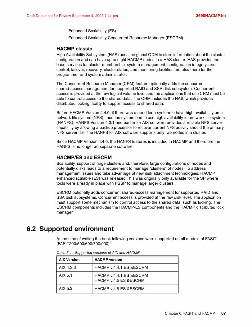
Draft Document for Review September 4, 2003 7:41 pm 3690HACMP.fm
– Enhanced Scalability (ES)
– Enhanced Scalability Concurrent Resource Manager (ESCRM)
HACMP classicHigh Availability Subsystem (HAS) uses the global ODM to store information about the cluster configuration and can have up to eight HACMP nodes in a HAS cluster. HAS provides the base services for cluster membership, system management, configuration integrity, and control, failover, recovery, cluster status, and monitoring facilities are also there for the programmer and system administrator.
The Concurrent Resource Manager (CRM) feature optionally adds the concurrent shared-access management for supported RAID and SSA disk subsystem. Concurrent access is provided at the raw logical volume level and the applications that use CRM must be able to control access to the shared data. The CRM includes the HAS, which provides distributed locking facility to support access to shared data.
Before HACMP Version 4.4.0, if there was a need for a system to have high availability on a network file system (NFS), then the system had to use high availability for network file system (HANFS). HANFS Version 4.3.1 and earlier for AIX software provides a reliable NFS server capability by allowing a backup processor to recover current NFS activity should the primary NFS server fail. The HANFS for AIX software supports only two nodes in a cluster.
Since HACMP Version 4.4.0, the HANFS features is included in HACMP and therefore the HANFS is no longer an separate software.
HACMP/ES and ESCRMScalability, support of large clusters and, therefore, large configurations of nodes and potentially disks leads to a requirement to manage “clusters” of nodes. To address management issues and take advantage of new disk attachment technologies, HACMP enhanced scalable (ES) was released.This was originally only available for the SP where tools were already in place with PSSP to manage larger clusters.
ESCRM optionally adds concurrent shared-access management for supported RAID and SSA disk subsystems. Concurrent access is provided at the raw disk level. The application must support some mechanism to control access to the shared data, such as locking. The ESCRM components includes the HACMP/ES components and the HACMP distributed lock manager.
6.2 Supported environmentAt the time of writing the book following versions were supported on all models of FAStT (FAStT200/500/600/700/900):
Table 6-1 Supported versions of AIX and HACMP
AIX Version HACMP version
AIX 4.3.3 HACMP v.4.4.1 ES &ESCRM
AIX 5.1 HACMP v.4.4.1 ES &ESCRMHACMP v.4.5 ES &ESCRM
AIX 5.2 HACMP v.4.5 ES &ESCRM
Chapter 6. FAStT and HACMP 87

3690HACMP.fm Draft Document for Review September 4, 2003 7:41 pm
The latest documents can be downloaded from:
– http://ssddom02.storage.ibm.com/techsup/webnav.nsf/support/fasttX00downloads
where X00 stands for 200, 500, 500, 700 or 900 depending upon your FAStT model.
6.2.1 General rulesThe primary goal of an HACMP environment is to eliminate single points of failure. In Figure 6-1 there is a diagram of a two-node HACMP cluster (this is not a limitation; you can have more nodes) attached to FAStT Storage Server through a fully redundant Storage Area Network. This type of configuration eliminates a fibre channel adapter, switch, or cable from being a single point of failure (HACMP itself protects against a node failure).
Using only one single FC switch would be possible (with additional zoning) but would be considered a single point of failure. If the FC switch fails, then you cannot access the FAStT volumes from either HACMP cluster node. So, with only a single FC switch, HACMP would be useless in the event of a switch failure. The example would be the recommended configuration for a fully redundant production environment. Each HACMP cluster node should also contain two fibre channel host adapters to eliminate the adapter as a single point of failure. Notice also that each adapter in a particular cluster node goes to a separate switch (cross cabling).
FAStT models can be ordered with more hosts ports. In the example mentioned above only two host attachments are needed. Buying additional mini hubs is not necessary but can be done for performance or security reasons. Zoning on the FC switch must be done as detailed in Figure 6-1 on page 88. Every adapter in the AIX system can see only one controller (these are AIX specific zoning restrictions, not HACMP specific).
Figure 6-1 HACMP cluster with attachment to FAStT
Important: Before installing FAStT in HACMP environment always read AIX readme file, FAStT readme for specific Storage Manager version and model and HACMP configuration info.
FAStT 900
AIX1 AIX2
A B A B
Host SideDrive Side
FC Switch FC Switch
Zone1Zone2
rs232
Heartbeats
IP Network
Controller
88 TotalStorage: FAStT Best Practices Guide
Draft Document for Review September 4, 2003 7:41 pm 3690HACMP.fm
6.2.2 Configuration limitationsWhen installing FAStT in HACMP environment there are some restrictions and guidelines to take into account. They are listed below. It does not mean that any other configuration will fail, but it could lead to unpredictable results, making it hard to manage and troubleshoot.
Applicable pSeries/AIX limitations (not HACMP specific)
The following AIX /pSeries restrictions which are relevant in a HACMP environment apply to FAStT200, FAStT500, FAStT600, FAStT700, and FAStT900 Storage Servers:
� Each AIX host can support two or four host bus adapters and up to two FAStT storage partitions, each requiring two HBA connections per FAStT storage server. Additional HBA pairs can be added to support additional FAStT Storage Servers.
� All volumes that are configured for AIX must be mapped to an AIX host group. Connecting and configuring to volumes in the default host group is not allowed.
� Other storage devices, such as tape devices or other disk storage, must be connected through separate HBAs and SAN zones.
� Each AIX host attaches to FAStT Storage Servers using pairs of Fibre Channel adapters (HBAs).
– For each adapter pair, one HBA must be configured to connect to controller A, and the other to controller B.
– Each HBA pair must be configured to connect to a single partition in a FAStT storage server or multiple FAStT Storage servers (fanout).
– To attach an AIX host to a single or multiple FAStTs with two partitions, 2 HBA pairs must be used.
� The maximum number of FAStT partitions (host groups) per AIX host per FAStT storage subsystem is two.
� Zoning must be implemented. If zoning is not implemented in a proper way, devices might appear on the hosts incorrectly. Follow these rules when implementing the zoning:
– Single-switch configurations are allowed, but each HBA and FAStT controller combination must be in a separate SAN zone.
– Each HBA within a host must be configured in a separate zone from other HBAs within that same host, when connected to the same FAStT controller port. In other words, only 1 HBA within a host can be configured with a given FAStT controller port in the same zone.
– Hosts within a cluster can share zones with each other.
– For highest availability, distributing the HBA and FAStT connections across separate FC switches will minimize the effects of a SAN fabric failure.
General limitations and restrictions for HACMP� Switched fabric connections only, no direct-attach connections allowed between host
node and FAStT.
� HACMP C-SPOC cannot be used to add a FAStT disk to AIX via the 'Add a Disk to the Cluster' facility.
� Single Node Quorum is not supported in a two node GPFS cluster with FAStT disks in the configuration.
� Concurrent and Non-Concurrent modes are supported with HACMP v4.4.1 & v4.5 and FAStT running SM v8.21 or v8.3, including Hot Standby and Mutual Take-over.
Chapter 6. FAStT and HACMP 89

3690HACMP.fm Draft Document for Review September 4, 2003 7:41 pm
� HACMP v4.4.1 & v4.5 is supported on p-690 (Regatta) LPAR clustered configurations.
� HACMP clusters can support 2 - 32 servers per FAStT partition. In this environment, be sure to read and understand the AIX device drivers queue depth settings as documented in the IBM FAStT Storage Manager v8.21(or v8.30) Installation and Support Guide for UNIX and AIX environments publication.
� Non-clustered AIX hosts can be connected to the same FAStT that is attached to an HACMP cluster, but must be configured on separate FAStT host partitions.
90 TotalStorage: FAStT Best Practices Guide

Draft Document for Review September 4, 2003 7:41 pm 3690GPFS.fm
Chapter 7. FAStT and GPFS for AIX
General Parallel File System (GPFS) is a cluster file system providing normal application interfaces and has been available on AIX operating system-based clusters since 1998. GPFS distinguishes itself from other cluster file systems by providing concurrent very high-speed file access to applications executing on multiple nodes of an AIX cluster.
In this chapter we describe configuration information for FAStT with GPFS in an AIX environment.
7
© Copyright IBM Corp. 2003. All rights reserved. 91

3690GPFS.fm Draft Document for Review September 4, 2003 7:41 pm
7.1 GPFS IntroductionGPFS for AIX is a high performance, shared-disk file system that can provide fast data access to all nodes in a cluster of IBM UNIX servers, such as IBM Cluster 1600, and IBM pSeries and IBM RS/6000® SP systems. Parallel and serial applications can easily access files using standard UNIX file system interfaces, such as those in AIX. GPFS allows the creation of a subset of the nodes which make up an AIX cluster called a nodeset which is defined as those members of the cluster which are to share GPFS data. This nodeset may include all the members of the cluster.
GPFS is designed to provide high performance by ‘striping’ I/O across multiple disks (on multiple servers); high availability through logging, replication and both server and disk failover; and high scalability. Most UNIX file systems are designed for a single-server environment. Adding additional file servers typically does not improve the file access performance. GPFS complies with UNIX file system standards and is designed to deliver scalable performance and failure recovery across multiple file system nodes. GPFS is currently available as Versions 1.5 and 2.1, and is available in a number of environments:
� IBM UNIX clusters managed by the Parallel System Support Programs (PSSP) for AIX licensed program.
� An existing RSCT peer domain managed by the Reliable Scalable Cluster Technology (RSCT) component of the AIX 5L operating system, beginning with GPFS 2.1.
� An existing HACMP cluster managed by the High Availability Multiprocessing (HACMP) licensed program.
GPFS provides file data access from all nodes in the nodeset by providing a global name space for files. Applications can efficiently access files using standard UNIX file system interfaces and GPFS supplies the data to any location in the cluster. A simple GPFS model is shown in Figure 7-1.
Figure 7-1 Simple GPFS model
In addition to existing AIX administrative file system commands, GPFS has functions that simplify multinode administration. A single GPFS multinode command can perform file
Application
GPFS
SSA/FCdriver
Application
GPFS
SSA/FCdriver
Application
GPFS
SSA/FCdriver
FC Switch/SSA Loops/.....FC Switch/SSA Loops/.....
ComputeNodes
IP Network
DiskCollection
92 TotalStorage: FAStT Best Practices Guide
Draft Document for Review September 4, 2003 7:41 pm 3690GPFS.fm
system functions across the entire GPFS cluster and can be executed from any node in the cluster.
GPFS supports the file system standards of X/Open 4.0 with minor exceptions. As a result, most AIX and UNIX applications can use GPFS data without modification, and most existing UNIX utilities will run unchanged.
High performance and scalabilityBy delivering file performance across multiple nodes and disks, GPFS is designed to scale beyond single-node and single-disk performance limits. This higher performance is achieved by sharing access to the set of disks which make up the file system. Additional performance gains can be realized through client-side data caching, large file block support, and the ability to perform readahead and write-behind functions. As a result, GPFS can outperform Network File System (NFS), Distributed File System (DFS) and Journaled File System (JFS). Unlike these other file systems, GPFS file performance scales as additional file server nodes and disks are added to the cluster.
Availability and recoveryGPFS can survive many system and I/O failures. It is designed to transparently failover locked servers and other GPFS central services. GPFS can be configured to automatically recover from node, disk connection, disk adapter, and communication network failures:
� In a IBM Parallel System Support Programs (PSSP) cluster environment, this is achieved through the use of the clustering technology capabilities of PSSP in combination with the PSSP Recoverable Virtual Shared Disk (RVSD) function or disk specific recovery capabilities.
� In an AIX cluster environment, this is achieved through the use of the cluster technology capabilities of either an RSCT peer domain or an HACMP cluster, in combination with the Logical Volume Manager (LVM) component or disk specific recovery capabilities.
GPFS supports data and metadata replication, to further reduce the chances of losing data if storage media fail. GPFS is a logging file system that allows the re-creation of consistent structures for quicker recovery after node failures. GPFS also provides the capability to mount multiple file systems. Each file system can have its own recovery scope in the event of component failures.
All application compute nodes are directly connected to all storage possibly via a SAN switch. GPFS allows all compute nodes in the node set to have coherent and concurrent access to all storage. GPFS provides a capability to use IBM’s SP™ Switch and SP Switch2 technology instead of a SAN. GPFS uses the Recoverable Virtual Shared Disk (RVSD) capability currently available on IBM’s RS/6000® SP and IBM Cluster 1600 platforms. GPFS uses RVSD to access storage attached to other nodes in support of applications running on compute nodes. The RVSD provides a software simulation of a storage area network over the SP Switch or SP Switch2.
7.2 Supported ConfigurationsGPFS runs on an IBM Cluster 1600 or a cluster of IBM pSeries nodes, the building blocks of the Cluster 1600. Within each cluster, your network connectivity and disk connectivity varies depending upon your GPFS cluster type.
Table 7-1 on page 94 summarizes network and disk connectivity per cluster type
Chapter 7. FAStT and GPFS for AIX 93

3690GPFS.fm Draft Document for Review September 4, 2003 7:41 pm
Table 7-1 GPFS clusters: network and disk connectivity
What is an SP cluster type and supported configurationsThe GPFS cluster type SP is based on the IBM Parallel System Support Programs (PSSP) licensed product and the shared disk concept of the IBM Virtual Shared Disk component of PSSP. In the GPFS cluster type SP (a PSSP environment), the nodes which are members of the GPFS cluster depend on the network switch type being used. In a system with an SP switch, the GPFS cluster is equal to all of the nodes in the corresponding SP partition which have GPFS installed. In a system with an SP switch2, the GPFS cluster is equal to all of the nodes in the system which have GPFS installed. That is, the cluster definition is implicit and there is no need to run the GPFS cluster commands. Within the GPFS cluster, you define one or more nodesets within which your file systems operate.
In an SP cluster type, GPFS requires the Parallel System Support Programs (PSSP) licensed product and its IBM Virtual Shared Disk and IBM Recoverable Virtual Shared disk components (RVSD) for uniform disk access and recovery.
Disk and software requirements within your GPFS are:
Table 7-2
GPFS Cluster type Network Connectivity Disk Connectivity
SP - PSSP SP Switch or SP Switch2 virtual shared disk server
RPD - RSCT Peer Domain An IP network of sufficient network bandwidth (minimum of 100Mb per second)
storage area network (SAN)-attached to all nodes in the GPFS cluster
HACMP An IP network of sufficient network bandwidth (minimum of 100Mb per second)
SAN-attached to all nodes in the GPFS cluster
Important: Before installing FAStT in GPFS environment always read AIX readme file and FAStT readme for specific Storage Manager version and model. Latest documents can be downloaded from:
� http://ssddom02.storage.ibm.com/techsup/webnav.nsf/support/fastt500downloads� http://ssddom02.storage.ibm.com/techsup/webnav.nsf/support/fastt600downloads� http://ssddom02.storage.ibm.com/techsup/webnav.nsf/support/fastt700downloads� http://ssddom02.storage.ibm.com/techsup/webnav.nsf/support/fastt900downloads
GPFS 2.1 and PSSP v3.5 running AIX 5L v 5.1
Supported FAStT model Storage Manager
FAStT 500 SM8.21, SM8.3, SM8.4
FAStT 600 SM8.33, SM8.4
FAStT 700 SM8.21, SM8.3, SM8.4
FAStT 900 SM8.3, SM8.4
GPFS 1.5 and PSSP v3.4 running AIX 5L v 5.1
Supported FAStT model Storage Manager
94 TotalStorage: FAStT Best Practices Guide

Draft Document for Review September 4, 2003 7:41 pm 3690GPFS.fm
What is an RPD cluster type and supported configurationsThe GPFS cluster type rpd is based on the Reliable Scalable Cluster Technology (RSCT) subsystem of AIX 5L. The GPFS cluster is defined over an existing RSCT peer domain. The nodes which are members of the GPFS cluster are defined via the mmcrcluster, mmaddcluster, and mmdelcluster commands. With an RSCT peer domain, all nodes in the GPFS cluster have the same view of the domain and share the resources within the domain. Within the GPFS cluster, you define one or more nodesets within which your file systems operate.
In an rpd cluster type, GPFS requires the RSCT component of AIX. The GPFS cluster is defined on an existing RSCT peer domain via the mmcrcluster command.
Disk and software requirements within the GPFS rpd cluster are:
Table 7-3
What is an HACMP cluster type and supported configurationsThe GPFS cluster type HACMP is based on IBM’s High Availability Cluster Multi-Processing/Enhanced Scalability for AIX (HACMP/ES) licensed product. The GPFS cluster is defined over an existing HACMP cluster. The nodes which are members of the GPFS cluster are defined via the mmcrcluster, mmaddcluster, and mmdelcluster commands. Within the GPFS cluster, you define one or more nodesets within which your file systems operate.
In an HACMP cluster type, GPFS requires IBM’s HACMP/ES licensed product over which the GPFS cluster is defined via the mmcrcluster command.
Disk and software requirements within a GPFS HACMP cluster are:
Table 7-4 I
FAStT 500 SM8.21, SM8.3, SM8.4
FAStT 600 SM8.33, SM8.4
FAStT 700 SM8.21, SM8.3, SM8.4
FAStT 900 SM8.3, SM8.4
GPFS 2.1 running AIX 5L v 5.1
Supported FAStT model Storage Manager
FAStT 500 SM8.21, SM8.3, SM8.4
FAStT 600 SM8.33, SM8.4
FAStT 700 SM8.21, SM8.3, SM8.4
FAStT 900 SM8.3, SM8.4
GPFS 2.1 and HACMP 4.5 or 4.4.1 running AIX 5L v 5.1
Supported FAStT model Storage Manager
FAStT 500 SM 7.1, SM8.21, SM8.3, SM8.4
GPFS 2.1 and PSSP v3.5 running AIX 5L v 5.1
Supported FAStT model Storage Manager
Chapter 7. FAStT and GPFS for AIX 95
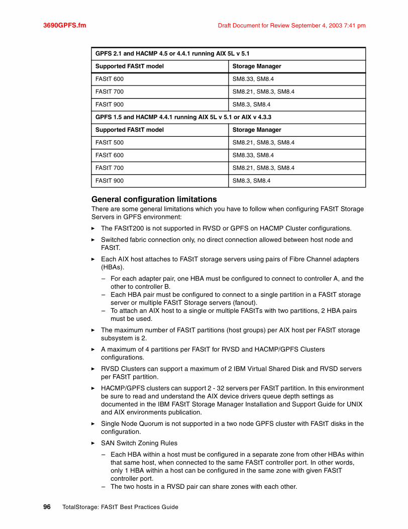
3690GPFS.fm Draft Document for Review September 4, 2003 7:41 pm
General configuration limitationsThere are some general limitations which you have to follow when configuring FAStT Storage Servers in GPFS environment:
� The FAStT200 is not supported in RVSD or GPFS on HACMP Cluster configurations.
� Switched fabric connection only, no direct connection allowed between host node and FAStT.
� Each AIX host attaches to FAStT storage servers using pairs of Fibre Channel adapters (HBAs).
– For each adapter pair, one HBA must be configured to connect to controller A, and the other to controller B.
– Each HBA pair must be configured to connect to a single partition in a FAStT storage server or multiple FAStT Storage servers (fanout).
– To attach an AIX host to a single or multiple FAStTs with two partitions, 2 HBA pairs must be used.
� The maximum number of FAStT partitions (host groups) per AIX host per FAStT storage subsystem is 2.
� A maximum of 4 partitions per FAStT for RVSD and HACMP/GPFS Clusters configurations.
� RVSD Clusters can support a maximum of 2 IBM Virtual Shared Disk and RVSD servers per FAStT partition.
� HACMP/GPFS clusters can support 2 - 32 servers per FAStT partition. In this environment be sure to read and understand the AIX device drivers queue depth settings as documented in the IBM FAStT Storage Manager Installation and Support Guide for UNIX and AIX environments publication.
� Single Node Quorum is not supported in a two node GPFS cluster with FAStT disks in the configuration.
� SAN Switch Zoning Rules
– Each HBA within a host must be configured in a separate zone from other HBAs within that same host, when connected to the same FAStT controller port. In other words, only 1 HBA within a host can be configured in the same zone with given FAStT controller port.
– The two hosts in a RVSD pair can share zones with each other.
FAStT 600 SM8.33, SM8.4
FAStT 700 SM8.21, SM8.3, SM8.4
FAStT 900 SM8.3, SM8.4
GPFS 1.5 and HACMP 4.4.1 running AIX 5L v 5.1 or AIX v 4.3.3
Supported FAStT model Storage Manager
FAStT 500 SM8.21, SM8.3, SM8.4
FAStT 600 SM8.33, SM8.4
FAStT 700 SM8.21, SM8.3, SM8.4
FAStT 900 SM8.3, SM8.4
GPFS 2.1 and HACMP 4.5 or 4.4.1 running AIX 5L v 5.1
Supported FAStT model Storage Manager
96 TotalStorage: FAStT Best Practices Guide

Draft Document for Review September 4, 2003 7:41 pm 3690GPFS.fm
� For highest availability, distributing the HBA and FAStT connections across separate FC switches will minimize the effects of a SAN fabric failure.
� No disk (LUN on FAStT) can be larger than 1 TB.
� You cannot protect your file system against disk failure by mirroring data at the LVM level. You must use GPFS replication or RAID devices to protect your data. (FAStT RAID levels)
Chapter 7. FAStT and GPFS for AIX 97

3690GPFS.fm Draft Document for Review September 4, 2003 7:41 pm
98 TotalStorage: FAStT Best Practices Guide

Draft Document for Review September 4, 2003 7:41 pm 3690bibl.fm
Related publications
The publications listed in this section are considered particularly suitable for a more detailed discussion of the topics covered in this Redpaper.
IBM RedbooksFor information on ordering these publications, see “How to get IBM Redbooks” on page 99. Note that some of the documents referenced here may be available in softcopy only.
� Fibre Array Storage Technology: A FAStT Introduction, SG24-6246
� IBM TotalStorage FAStT700 and Copy Services, SG24-6808
� IBM TotalStorage FAStT900/600 and Storage Manager 8.4, SG24-7010
� IBM TotalStorage Solutions for xSeries, SG24-6874
� IBM SAN Survival GUide, SG24-6143-01
� Introduction to Storage Area Networks, SG24-6900
Online resourcesThese Web sites and URLs are also relevant as further information sources:
� IBM Redbooks website
http://wwww.redbooks.ibm.com/
� IBM TotalStorage FAStT website
http://www.storage.ibm.com/disk/fastt/index.html
How to get IBM RedbooksYou can search for, view, or download Redbooks, Redpapers, Hints and Tips, draft publications and Additional materials, as well as order hardcopy Redbooks or CD-ROMs, at this Web site:
ibm.com/redbooks
Help from IBMIBM Support and downloads
ibm.com/support
IBM Global Services
ibm.com/services
© Copyright IBM Corp. 2003. All rights reserved. 99

3690bibl.fm Draft Document for Review September 4, 2003 7:41 pm
100 TotalStorage: FAStT Best Practices Guide

Draft Document for Review September 4, 2003 7:41 pm 3690IX.fm
Index
Aaccess logical drive 65, 70access LUN 55ADT 7, 54, 56alert 5, 77Alert Delay Period 56alert notification 7, 56array configuration 37array size 37attenuation 31Automatic Discovery 64
Bbattery 3, 8, 34–35, 45–46block size 42bootp 7, 62
Ccable
labeling 18–19management 18–19types 31
cabling 31FAStT cabling configuration 20
cache 35, 43–44block size 44, 47flushing 45, 47memory 73mirroring 45–46read ahead 73read-ahead multiplier 73settings 45
cache hit percentage 73channel protection 38cluster 70, 86, 88
Microsoft Cluster Server 4Novell cluster 4Veritas Cluster 4
Concurrent Resource Manager (CRM) 87controller ownership 39–41, 54, 56, 72copy
FlashCopy 6Remote Volume Mirroring 13, 31, 48VolumeCopy 6
copyback 75
Ddata striping 34–35Default Group 69default group 43, 68defragment 74disk mirroring 34–35
© Copyright IBM Corp. 2003. All rights reserved.
DMP 55Dynamic Capacity Expansion (DCE) 75Dynamic Logical Drive Expansion (DVE) 75Dynamic RAID Level Migration (DRM) 75Dynamic Reconstruction Rate (DRR) 75Dynamic Segment Sizing (DSS) 75
EEvent Monitor 5, 77EXP500 2EXP700 3
Ffabric 12failover 7, 10, 32, 41, 46, 54, 56–57failover alert delay 57–58FAStT
evolution 2MSJ 43utilities 5
FAStT200 2FAStT600 2FAStT600 Turbo 3FAStT700 3FAStT900 3feature key 48Fibre Channel 11firmware 65, 82–83FlashCopy 6, 50, 75–76
logical drive 6flushing 45, 47frame switch 12free space node 74
GGPFS 92
HHACMP 4, 85–86heterogeneous host 42, 68High Availability Subsystem (HAS) 87host agent 55, 64, 66, 77host group 69–70host port 69host type 67hot_add 70hot-scaling 26hot-spare 66–67, 75
global 66hot-spare drive 47hub 12
101

3690IX.fm Draft Document for Review September 4, 2003 7:41 pm
Iin-band 5, 63, 65–66inter-disk allocation 52Inter-switch links 12IOPS 42IP address 63ISL 12, 49
JJFS 50–51
Llabeling 18large I/O size 7LDM 52Linux 55, 70, 83LIP 15, 65load balancing 33, 56load sharing 33logical drive 39
base 7Flashcopy 6primary 6, 41, 48, 76secondary 6, 41, 48, 76
logical drive transfer alert 56Logical Volume Manager (LVM) 93Logical Volume Manager. See LVMlongwave 31loop 12LUN
assignment 40masking 43
LVM 50–51
Mmapping 69–70microcode 65, 67modal dispersion 31modification operation 74modification priority 74MSJ 43, 55multi-mode fiber (MMF) 31multipath driver 54
NNetWare 56network parameters 7node failover 86nodeset 92node-to-node 12NVSRAM 7, 65
Oout-of-band 5, 63, 66
PParallel System Support Programs (PSSP) 93password 66PCI bus 38PCI slots 32performance 30, 34, 37, 41, 45–46performance monitor 42, 46, 72Persistent reservations 6planning 30point-to-point 12preferred controller 39–41, 54, 57premium features 3, 48
Rrack 16RAID
controller 3level 4, 34, 36–37, 67
RAID level 73RDAC 5, 7, 33, 54, 56, 65read caching 45Read Link Status Diagnostic. See RLSread percentage 73read-ahead multiplier 44–45, 68Recovery Guru 57Recovery Profile 8Redbooks Web site 99
Contact us xiRedundant Disk Array Controller See RDACReliable Scalable Cluster Technology (RSCT) 86Remote Volume Mirroring 13, 31, 48, 74RLS 8round-robin 56rpd 95RVM.See Remote Vlume Mirroring
SSAN 10–11SCSI 11segment size 42, 68serial connection 62serial port 62Service Alert 77, 80shortwave 31single mode fiber (SMF) 31SMclient 63SMdevices 5SMTP 77SNMP 77Storage Area Network<$nopage. 10storage bus 10Storage Manager 4
Agent 5Client 4
storage partition 4storage partitioning 3, 40, 42–43, 68sub-disk 53switch 12synchronization 48, 76
102 IBM TotalStorage: FAStT Best Practices Guide

Draft Document for Review September 4, 2003 7:41 pm 3690IX.fm
Tthroughput 42, 44, 46Total I/O 72transfer rate 38tuning 30
Uuser profile 78userdata.txt 78–79utilities 5
VVeritas Volume Manager 53volume 39VolumeCopy 6, 74VxVM 53
WWizard
Create Copy 6world-wide name 69write caching 46write-back 44, 46write-through 44, 46WWN 43
Zzone 14–15
broadcast 16hardware enforced 15software enforced 15types 15
zoning 14
Index 103

3690IX.fm Draft Document for Review September 4, 2003 7:41 pm
104 IBM TotalStorage: FAStT Best Practices Guide


®Draft Document for Review September 4, 2003 7:41 pm
INTERNATIONAL TECHNICALSUPPORTORGANIZATION
BUILDING TECHNICAL INFORMATION BASED ON PRACTICAL EXPERIENCE
IBM Redbooks are developed by the IBM International Technical Support Organization. Experts from IBM, Customers and Partners from around the world create timely technical information based on realistic scenarios. Specific recommendations are provided to help you implement IT solutions more effectively in your environment.
For more information:ibm.com/redbooks
Redpaper
IBM TotalStorage: FAStT Best Practices Guide
FAStT Concepts and Planning
Implementation and Tuning Tips
Advanced Topics
This Redpaper is a best practices document for FAStT. It is aimed at giving the basics on how to configure your installation. It is a compilation of recommendations for planning, designing, implementing and maintaining FAStT storage solutions.
Setting up a FAStT Storage Server can be a complex task. There is no single configuration that will be satisfactory for every application or situation. This Redpaper provides a starting point on how to plan and configure your installation to make it reliable, performant and easier to manage.
The Redpaper provides the conceptual framework for understanding FAStT in a Storage Area Network and includes recommendations, hints and tips for the physical installation, cabling and zoning. Although no performance figures are included, the document discusses performance and tuning of various components and features to guide you when working with FAStT.
The last two chapters of the book present and discuss HACMP and GPFS as they relate to FAStT.
Back cover