recovery performance in redundant campus network290003/fulltext01.pdf · set up and configured in a...
TRANSCRIPT

Technical report, IDE0960, December 2009
Recovery Performance in Redundant
Campus Network
Master’s Thesis in Computer Systems Engineering
Sergo Mchedlishvili
Master’s Thesis in Computer Networks Engineering
Girinandan B. Srinivasa
School of Information Science, Computer and Electrical Engineering Halmstad University
Recovery Performance in Redundant Campus Network
2
Recovery Performance in Redundant Campus Network
Master’s Thesis in Computer Systems Engineering
Master’s Thesis in Computer Networks Engineering
School of Information Science, Computer and Electrical Engineering
Halmstad University
Box 823, S-301 18 Halmstad, Sweden
December 2009
3
Preface
“Truth is what stands the test of experience.” "Anyone who has never made a mistake has never tried anything new."
- Albert Einstein
This thesis is a part of the Master programme in Computer & Electrical Engineering which is
carried out in Halmstad University, Sweden for spring semester 2009.
We thank wholeheartedly the University, and our supervisors Olga Torstensson and Tony
Larsson for their support, help and guidance that was very valuable in different stages of the
work. Also we would like to thank our family and friends for their support and strength they
provided us during the programme.
Sergo Mchedlishvili (Master’s Programme in Computer System Engineering)
Girinandan B. Srinivasa (Master’s Programme in Computer Network Engineering)
Halmstad University, December 2009

Recovery Performance in Redundant Campus Network
4
Abstract Over years, there have been tremendous changes in internetworking technologies and there are a number of real time applications that are flooded into the market. Most real-time applications are sensitive to traffic loss because of their nature of exchanging data without acknowledgement. In any type of data network, redundancy is important to backup and recover the connectivity without human intervention in case of device or link failure. However, it is very crucial to design an optimal redundant network, particularly for real-time applications providing minimal losses during fail-over. Configuration of redundancy in different networks varies and depends on the equipment and network design itself. This thesis focuses on the redundancy needed in campus network design which is quite popular nowadays in most of medium and large enterprises, universities or government agencies. Two major designs of redundancy are studied: default gateway redundancy and routed access. In the first option, the one logical segment of network uses common L2 switches while in the other – the same segment is constructed with more expensive advanced multilayer switches. The network is built in the lab environment. As an example of real-time communication the VoIP call is simulated in the network. The failures on different areas of nodes or links are caused manually. Results of packet loss during fail-over are recorded. The baseline of recovery performance is constructed using these results which are derived from different scenarios using different configurations and equipment. The baseline data is evaluated and conclusion is made on the trade-offs, limitations, advantages and disadvantages of the redundancy options in the campus network design. The work done in this thesis is supportive for network architects and designers to take into consideration the equipment and configuration to be used when implementing redundancy for real-time communications. The results and conclusion will support them in choosing the options for constructing the redundant network, or taking into account the trade-offs when migrating from one option to another.

5
Keywords:
Campus Network
Routed Access
Default Gateway Redundancy
First Hop Redundancy
Hot Standby Routing Protocol (HSRP)
Enhanced Interior Gateway Routing Protocol (EIGRP)
Open Shortest Path First (OSPF)
Voice over IP (VoIP)

Recovery Performance in Redundant Campus Network
6
List of Acronyms ABR Area Border Router ARP Address Resolution Protocol AS Autonomous System ASBR Autonomous System Boundary Router AVF Active Virtual Forwarder AVG Active Virtual Gateway BDR Backup Designated Router BIA Burnt-In Address CAM Content Addressable Memory CEF Cisco Express Forwarding CME Cisco Call Manager CPU Central Processing Unit DR Designated Router EIGRP Enhanced Interior Gateway Routing Protocol GLBP Gateway Load Balancing Protocol HSRP Hot Standby Router Protocol ICMP Internet Control Message Protocol IGP Interior Gateway Protocol IP Internet Protocol L2 Layer 2 L3 Layer 3 LAN Local Area Network LSA Link State Advertisement MAC Media Access Control MOS Mean Opinion Score NBMA Non-Broadcast Multiple Access NSSA Not-So-Stubby Area OSPF Open Shortest Path First PAgP Port Aggregation Protocol QoS Quality of Service RID Router ID RIP Routing Information Protocol SIP Session Initiation Protocol SPF Shortest Path First SVI Switch Virtual Interface ToS Type of Service UDLD UniDirectional Link Detection VAD Voice Activation Detection WAN Wide Area Network VLAN Virtual Local Area Network VLSM Variable Length Subnet Masking VoIP Voice over IP VRRP Virtual Router Redundancy Protocol

7
Contents Preface ___________________________________________________________________ 3
Abstract ___________________________________________________________________ 4
Keywords __________________________________________________________________ 5
Contents __________________________________________________________________ 7
1.0 Introduction ____________________________________________________________ 8
1.1 Motivation _________________________________________________________________ 8
1.2 Goal _______________________________________________________________________ 9
1.3 Methodology ________________________________________________________________ 9
2.0 Campus Network Design _________________________________________________ 10 Figure 2.01 Redundant Campus Network __________________________________________________ 10
2.1 Gateway Redundancy in Campus Network _____________________________________ 11 2.1.1 Hot Standby Router Protocol (HSRP) ______________________________________________ 11 2.1.2 HSRP Process __________________________________________________________________ 12
2.1.3 Gateway Load Balancing Protocol (GLBP) ____________________________________ 13
2.1.4 Design Recommendations __________________________________________________ 15
2.2 Routing In Campus Network ______________________________________________ 16 Figure 2.2.1: Layer 2 switches at Access Layer _____________________________________________ 17
2.2.1 Enhanced Interior Gateway Routing Protocol (EIGRP) _________________________ 20
2.2.2 Open Shortest Path First (OSPF) ____________________________________________ 21 Table 2.1.1: OSPF LSA Types _________________________________________________________ 24
3.0 Implementation and Tests ________________________________________________ 27 Table 3.1: Hardware used to build network ________________________________________________ 27 Table 3.2: Applications running on network _______________________________________________ 27 Table 3.3: Network configuration of hosts ________________________________________________ 28
3.1 Routed Access Layer Design Implementation _________________________________ 29 Figure 3.1: Routed access Network design _________________________________________________ 29 Table 3.1.1: Routed access Ports Configuration _____________________________________________ 30 Table 3.1.2: TRACERT command output showing route from Host2 to Host1 _____________________ 30 Table 3.1.3: Test results for packet loss ___________________________________________________ 31 Figure 3.2.1: Gateway Redundancy Network design _________________________________________ 33 Table 3.2.1: Gateway Redundancy port design _____________________________________________ 33 Figure 3.2.3: Broken link between Dist21 and Acc22 nodes ___________________________________ 34 Table 3.2.2: Test results _______________________________________________________________ 35
4.0 Result_________________________________________________________________ 36 Figure 4.1: Examples of results obtained from VQ Manager from different scenarios. _______________ 36 Figure 4.2: Comparison of packet loss in different scenarios ___________________________________ 37
5.0 Conclusion ____________________________________________________________ 39
6.0 References _____________________________________________________________ 40
7.0 Appendix ______________________________________________________________ 42

Recovery Performance in Redundant Campus Network
8
1.0 Introduction
During past decades, internetworking has rapidly evolved and grown in both size and capacity. The emerging trends and business requirements have formulated new challenges in the field. The network technologies and equipment have been developed, advanced to provide robust and reliable computer networks. High-availability of the network has always been important in the internetworking world. Redundancy can help to create high-availability and is important to have traffic rerouted in case of failure in network without human intervention. Wise planning and configuration of redundancy can thus provide high-available networks. However, because use of modern equipment is not the guarantee of 100% availability, the various redundancy techniques have been designed to achieve the high recovery performance of network in case of failure. Costs of various issues such as equipment, transmission medium, management and administration for designing redundant and high-available networks vary. Depending on the combination of device and configuration, the various convergence performances will be achieved for various scenarios. One of the main challenges of any network design is the cost effectiveness when deploying it. Wise implementation and tuning of high-available redundant networks can provide low cost network whilst achieving high performance in recovery after failure.
1.1 Motivation
The majority of real-time applications use connectionless protocol sessions for two main reasons i.e. firstly, there is no point to use techniques of received data acknowledgement and retransmission of lost data, as data transmitted only has meaning at the given time and its significance is thus lost when retransmitted later; secondly, connectionless protocols have much less overhead than connection-oriented ones. For example, voice over IP call session packets are not acknowledged because of its real-time nature. It is meaningless that the speech lost during network failure is repeated after that the recovery process is finished. Therefore, packets lost during the convergence period cannot be retransmitted and they are lost eventually. These factors make convergence time very crucial in computer networks, especially when real-time applications are implemented. Campus network design is one of the popular high-available network architectures generally consisting of blocks of multiple, local area networks building one enterprise network. Design and topology of campus network provides, among other benefits, fast convergence in case of failure of node or link. In most cases of failure, the convergence of network is not dependent on routing protocol updates because of using equal-cost, redundant links where the traffic restoration actually depends on physical detection of link absence. In this case, if one of the links is down, the traffic is rerouted to another redundant one without having the routing table updated. Implementation of this kind of redundancy requires advanced, multilayer switching devices. However in some cheaper alternatives of network designs, where major parts of the network is constructed using ordinal L2 switches, there exist some points in the network where convergence time is not so deterministic and relies on timer-based redundancy protocols. In such parts of a network, fine

9
tunings are necessary to increase the recovery performance of network in case of failure. The results of such tunings must be evaluated to be able to achieve high performance of convergence, similar to the deterministic, non-timer based one. It is important to understand the pros and cons of the above described network redundancy scenarios. By performing the tests regarding failures and switchovers in these redundant networks, the baseline can be built for convergence performance which will help to realize the trade-offs to be done while constructing one or the other high-available network design.
1.2 Goal
The goal of this thesis is to study convergence performance in two different options of redundancy in campus network design: Routed Access and Default Gateway Redundancy. By evaluating the results of the tests, it will be possible to define the advantages or disadvantages of one or the other of these redundancy options possible to use in campus network design. The study of these scenarios will help to build baseline for convergence performance and conclude what kind of trade-offs have to be taken into account while building redundancy using Routed Access and Default Gateway Redundancy. The thesis also explains the reasons for differences in convergence performance and describes best-practices for setting up and configuring optimal redundant campus network.
1.3 Methodology
The major options of campus network design using EIGRP and OSPF routing protocols are set up and configured in a lab environment; the same topology is also used for gateway redundancy HSRP and GLBP. Campus network with two distribution block networks is constructed using Cisco multilayer switches in all of the three hierarchal layers of network and Cisco router used as Call Manager Express (CME) for supporting VoIP call setup for test purposes. Failures on different points of network in various scenarios are caused manually during VoIP call session between two hosts located in two different distribution blocks of network. The results of packet loss during network convergence are recorded by use of a Quality of Service (QoS) measurement software called VQ Manager. VQ Manager only provides results in percentage and does not show the exact number of packets lost during failure of link or node. Therefore another software, called “Simple Network Tester” is also used which simulates VoIP call traffic and, at the same time, records the exact number of lost packets. The tunings of redundancy protocols are done in one scenario and then the results and consequences are evaluated and compared to those derived from other scenarios to provide a conclusion.

Recovery Performance in Redundant Campus Network
10
2.0 Campus Network Design
There are many types of campus network designs which provide high-availability, flexibility, scalability and manageability. The design of each option depends on functionality available in the network nodes and also it can be varied by the network designer or architect to achieve the optimal performance in a given network, or sometimes to reduce design costs. The major design for all kind of campus networks is the same. In this design the physical network consists of three main hierarchical layers which are core layer, distribution layer and access layer [1]. They are often referred as backbone, workgroup and local-access layer respectively [1]. Each part of the network has its own definition and function.
Each hierarchical layer of the network may contain different kind of devices but, in most designs, the core layer and distribution layer consist of multilayer switches. Multilayer switches are capable of providing routing, as well as wire-speed packet switching and tuneable load-balancing, using Cisco express forward technology. The core layer of the network typically consists of two, multilayer redundant switches and provides high-speed transmission between distribution blocks. Distribution blocks consist of two, multilayer redundant switches and several access layer switches. Two redundant distribution switches are aggregating traffic flow from distribution block out to other ones or to the WAN. In addition QoS policies and access-lists are usually implemented on distribution switches. Hosts are connected to access layer switches and the number of access layer switches in the distribution block varies and depends on the number of hosts (end-user stations or servers) as shown in figure 2.01.
Figure 2.01 Redundant Campus Network
The multilayer switches of core and distribution layer are usually interconnected with 10Gig fiber-optic cables to provide high throughput of aggregated traffic between distribution blocks. Connections between distribution and access layer switches are usually provided by 1Gig fiber-optic cables [1].

11
2.1 Gateway Redundancy in Campus Network
The most popular, and time-tested, option for redundancy in campus network design is gateway redundancy, also known as first hop redundancy [2]. In this design, the L2/L3 border resides at the distribution layer. The distribution multilayer switches are connected to core multilayer switches with equal-cost links using routed interfaces that run routing protocols. Access layer devices are L2 switches and the equal-cost links connecting to distribution multilayer switches are L2 links. From the host‘s perspective, the redundancy is provided by one of the redundancy protocols running on Distribution switches: Hot Standby Router Protocol (HSRP), Virtual Router Redundancy Protocol (VRRP) and Gateway Load Balancing Protocol (GLBP). HSRP and GLBP are Cisco-proprietary protocols while VRRP is industry standard one.
Figure 2.1.1: Layer 2 switches at Access Layer
2.1.1 Hot Standby Router Protocol (HSRP)
HSRP has, over the years, been well-known as a time tested way of obtaining 100% uptime and redundancy for networks that run IP; also it recovers from first hop failures in devices. HSRP shares a common IP and MAC address, i.e., it creates a single virtual router out of a group that is running HSRP protocol. This group exchange status messages with each other, hence sharing responsibilities. The host sends packets to a virtual IP and MAC address, therefore being transparent from the change over mechanism. This protocol was developed by Cisco and, therefore, is used proprietarily. HSRP was created as network resilience as it is not feasible with every host running because most of the hosts support a single, default gateway.

Recovery Performance in Redundant Campus Network
12
2.1.2 HSRP Process
HSRP was designed for hosts that are not capable of discovering, dynamically, the default gateway or a default router. Running a dynamic router discovery on hosts is not feasible as it will cause administrative overhead and security issues. HSRP represents a rather agile solution for redundancy. By using HSRP, a set of hosts on a virtual LAN has an illusion that they are serving a single router; this set is known as HSRP group [2]. A single router is elected as to forward packets to this group. This router is known as an active router. In case of failure, a standby router resumes the work of forwarding packets. Even though many routers may run HSRP, only the active router is responsible for the forwarding of packets. In order to minimize the traffic between routers, only the active and standby routers exchange updates periodically once the election for active and standby is completed. Each group has a well-known IP and MAC address. When a fail-over occurs, the new active router uses gratuitous ARP request on itself to flood the switch CAM table in order to associate the virtual MAC address with the physical port to which it is connected.
Features
Pre-emption: This feature in HSRP is designed for enabling routers with greater priority to become the active router. By default, HSRP priority is 100 and can be configured manually. In case of a tie, the highest active IP takes over to become active router. Once the active router is up and running, which was down due to failover, it will make other routers to resume back to standby state by sending a coupe message. This feature has to be configured carefully as it may lead to network outages [2].
Interface Tracking: This is a feature used by HSRP for tracking interface status. If an interface is down, then the priority is reduced. This allows the router with greater priority to become the active router. If multiple interfaces are down, then it is reduced in a cumulative way, set usually by a value of 10 per interface [2].
BIA: This is an HSRP feature that enables the use of a burnt-in interface MAC address, instead of HSRP MAC. This feature was enabled for token ring implementations. The major drawback of using BIA is that, when a router becomes active, this will send a gratuitous ARP which cannot be handled by many hosts [2].
Authentication: This contains a shared key which is clear text shared between HSRP peers within the packet. This prevents other routers from learning about HSRP timers and priority values [2].
HSRP also supports other features, like multiprotocol label switching, virtual private networks, ICMP redirects, and token ring implementations.

13
HSRP Timers
Hello timer: Hello time is the approximate time that routers send in a hello packet to indicate
that the peer router is active [2].
Hold timer: Hold time is the approximate time that standby router will declare that the peer is dead and becomes active [2].
These timers are tuneable and are tuned in a campus network design to obtain minimum convergence and therefore making a network high available.
2.1.3 Gateway Load Balancing Protocol (GLBP)
GLBP gateway load balancing protocol is a Cisco proprietary; this protocol was designed in 2005 [3] for first hop redundancy. It differs from other first hop routing protocols in a way that it has the ability to load balance over multiple gateways. It is similar to other first hop routing protocols in a manner that it has an election for the active router. GLBP elects an Active Virtual Gateway [3]. The Active Virtual Gateway assigns virtual MAC to each of the other GLBP running routers. Also, it assigns each network host to one of the GLBP routers. The router that receives MAC address assignment is known as active virtual forwarders. GLBP operates almost in a similar way to HSRP; here there is a virtual gateway that forwards packets, even in standby mode, which is an improvement over HSRP.
Components of GLBP
Active Virtual Gateway (AVF): This feature is the one that makes GLBP a unique gateway redundant protocol and is also responsible for its operation. Active Virtual Gateway is a group elected which will answer all the ARP requests for the virtual router’s IP address and MAC address that is assigned, depending on the load balancing algorithm configured and in use [3].
Virtual Gateway Redundancy: Virtual gateway redundancy works in similar fashion as it works in HSRP. Active and standby gateway is defined. If the active gateway fails then the standby will resume responsibilities of forwarding packets, meanwhile a new standby is elected from the group of listening gateways [3].
Active Virtual Gateway Election: An active virtual gateway is elected primarily by GLBP priority, which is configurable. In case of a tie, then the highest active IP address will be elected as the active virtual gateway; likewise in HSRP active router election [3].
Active Virtual Forwarder (AVF): Within the group of GLBP of virtual forwarder, one is elected as the active virtual forwarder for a given MAC address and, hence, it is responsible for all the forwarding of the packets sent to that MAC address [3].

Recovery Performance in Redundant Campus Network
14
Virtual Forwarder Redundancy: Virtual forwarder redundancy is similar to virtual gateway redundancy, i.e. one of the gateways will take over for virtual MAC if active virtual forwarder fails [3].
GLBP States
GLBP states for the virtual forwarder can be one of the following states:
Disabled: Indicates that a virtual IP is not yet configured or learnt yet also other GLBP configurations exist [4].
Initial: The virtual IP is configured or learnt but the virtual gateway configuration is not yet complete, indicating an interface is not up [4].
Listen: This indicates that GLBP hello packets are received via the virtual gateway and is ready to change to the next state [4].
Speak: Virtual gateway is attempting to take over as the active or standby [4].
Standby: Indicates that it is ready to go to active state if the active virtual router fails [4].
Active: Indicates that here is an active virtual gateway responding to ARP requests for the virtual IP configured [4].
GLBP Timers
Hello: This is the time taken for GLBP hello packets to be exchanged between AVG and AVF; this is tuneable [4].
Hold: This is the time taken for a GLBP standby gateway to wait to become active. When this timer expires, it declares that AVF is dead and AVF is replaced [4].
Redirect: This is time for the secondary virtual forwarder to remain valid after the primary forwarder becomes unavailable. It can be tuned as well [4].
Load Balancing
GLBP provides flexibility for routers in implementing load balancing, although some trade-off for the CPU in operation occurs. The ways in which GLBP load balancing can be configured are as follows:

15
None: When no load balancing occurs on a GLBP router, this protocol operates in a similar fashion to HSRP. The active virtual gateway will only respond to ARP request with its own MAC address and virtual forwarder. All traffic will be, henceforth, forwarded with no occurrence of load balancing. This means that load balancing is not configured and GLBP works like HSRP [4].
Weighted: This is a GLBP load balance feature that will place weights on every device while calculating the amount of load sharing through MAC assignments based on the values of GLBP groups. The AVG will perform load balancing [4].
Host dependent: This is where the MAC address of the host is used to determine which virtual forwarder will be used as a gateway. As long as the number of virtual forwarders is constant, the host will use the same virtual forwarder’s MAC address for traffic forwarding [4].
Round Robin: With round robin, each virtual forwarder MAC is used sequentially in ARP replies of virtual IP address [4].
GLBP Advantages
This makes good use of network resources as none of the routers are idle. It also offers network traffic which is shared among hosts based on the load balancing algorithm used. It lowers administration costs as it uses the common default gateway, administration of groups and gateway is not required [4].
2.1.4 Design Recommendations
Access Layer Tuning
UDLD (Unidirectional Link Detection) is used for protection against one way up/up connection. In fiber-optic topologies, physical misconnections will cause problems. To mitigate such issues, the use of UDLD is necessary. UDLD will automatically disable those ports which are misconfigured [5].
If VLAN trunking protocol is used, then use of transparent mode also prunes all unused VLAN with trunks set on/on with no negotiate [5].

Recovery Performance in Redundant Campus Network
16
PAgP settings should be matched [5].
Redundancy should be kept simple. Complex redundancy does not always make a network resilient. Sometimes, higher redundancy makes management of network very complicated. HSRP/GLBP should be used for First Hop Redundancy and asymmetric routing and unicast flooding should be avoided [5].
Distribution Layer Tuning
Using equal cost redundant connections to core avoids black holes in the network. Also, to implement faster convergence on routing protocols, summarization should be used. For the distribution/access layer, HSRP/GLBP is used as a redundancy mechanism and delays are tuned for optimum convergence [5].
Core Layer Tuning
Building core layer triangles for the redundant path is the best way of implementing convergence. For point-to-point link, core topology building square for redundancy is not a good idea; change in up/down link will be propagated immediately for other layers. Load sharing equal cost links are the best way to implement core layer links and also tune the timers for millisecond convergence [5].
2.2 Routing In Campus Network
Over the years in the field of internetworking, redundancy issues are finding new dimensions. Implementing routing protocols at the access layer design is the idea of Routed Access or routing in campus. Routing in campus network provides many advantages; it makes the campus network design high-available, i.e. it reduces convergence time making it a redundant with equal cost load balancing. Spanning tree loops will be completely eliminated, since all links connecting multilayer switches are routed links. It is also easy to manage layer 3 routing protocols because the whole campus design is a single process domain.
One of the alternatives of campus network design where multilayer switches are used in access layer is a newly emerged one. These multilayer switches run routing protocols and are connected with distribution layer switches using routed interfaces. The layer 2 interfaces are used for connection to hosts. In other words, the L2/L3 border has been relocated from distribution figure 2.2.1 to access layer switches, as shown in the figure 2.2.2. This design is called Routed Access Layer design.

17
Figure 2.2.1: Layer 2 switches at Access Layer
Figure 2.2.2: routed access layer design
Migrating from layer 2 to layer 3 routed access, the default gateway is shifted from the distribution layer to the access layer, so it is not necessary to configure HSRP or GLBP for the redundancy, as redundancy is taken care of by routing protocols. This is a noticeable change in the design with the implementation of layer 3 design. There is an enhancement in QoS and

Recovery Performance in Redundant Campus Network
18
security. There are many more added features of making routing at the access layer: tools for troubleshooting, like ping and trace route, are available; improved convergence, simplicity for multicast traffic and also load balancing. However the primary interest is the improvement in the convergence of the network
Redundant Links
To make a campus network high-available for faster convergence, the basic requirements are to have redundant links with redundant switches. The use of redundant switches with equal cost redundant links, having two entries in the CEF (Cisco Express Forwarding) table, one as primary and other as the backup, enhances the network stability. Under normal conditions, packets are forwarded on both links. After the failure of a link or a switch, there is an entry of the change which has occurred. At this point, there is no need for looking up a new route and wait for response. The time taken for the switch to route packets on the backup path is minimal. It is forwarded, normally, on the other link and, this time, is equal to the time taken for detecting link failure. This failure detection is dependent on parameters called debounce time and carrier delay. The recommended design for high available network is to use 10Gbit Ethernet or fiber- optic. For optical fiber cables, there is a separate detection mechanism by enabling a protocol called UDLD. In the 10Gbit Ethernet cables, we have a mechanism for fault tolerance. Protocols like 803.z [5] detect and update the hardware and software failure. This mechanism is a huge advantage in the layer 3 access design which adds on to the convergence [5].
Load Sharing and Cisco Express Forwarding
Load sharing is a mechanism of balancing load on multiple links to a particular destination. Load sharing can happen in two ways, i.e. on a per-destination, or per-packet, basis. Per-destination load sharing is a method whereby load is shared according to destination address. If there are two paths to the same network, all packets to one destination could be travelling through one path and, for second destination, the second path could be used. Also, for the third destination, the first path may be used. This is the default method used on all Cisco switches [5].
Per-packet load sharing is another method available for a user with express forwarding. The main motivation of this method is that one packet is sent out on one exit interface while the other packet is sent over the other one, even though the packet is destined for the same destination. This can be configured for unequal cost sharing meaning lower links can get lesser packets to handle. The flaws of this kind of implementation are that packets destined for the same destination can arrive in different order as they are using different links. This is not suitable for voice applications as the packets might arrive out of order [5].
These load sharing mechanisms are available with the Cisco express forwarding technique. This technique is an advanced and highly efficient switching process. It has a forwarding

19
information base which is a mirror image of the route table. This also maintains an adjacency table which contains the Layer 2 information of the neighbour. Both these tables are created when the device boots for the first time, and is stable; thereafter, all the packets are forwarded from looking up from these tables and this is a very efficient method.
Route Convergence Hot Fix
The important task of the network convergence is to handle the single point of failure on the link from distribution to access node. This is the weakest part of the network in terms of redundancy. The recovery time after failure depends on time for retrieving new routes and updating the routing tables. Even though the link failure depends on the above mentioned parameters, it is recommended routing protocol hello, and dead timers, are tuned for effective detection and recovery of the routes. Also, for protection from flapping links, it is recommended to use the mechanism of IP dampening [5].
IP Event Dampening
If the interface state change occurs, i.e. an interface is administratively down/up or flaps, the routing protocol has to recalculate the best path to reach the destination each time. This is overcome by the feature known as IP event dampening. This introduces an exponential delay mechanism to improve convergence. This feature improves overall network stability [5].
Summarization in Campus Network
Summarization is an important parameter in making campus network high-available. In case of a failure of link or flapping links in the network, the routing protocols should not send updates everywhere in the network as it will generate an update that leads to recalculation of the routes over and over, leading to a devastating effect in building tables again and again. If the link is a flapping, it is a drastic scenario where it will affect the convergence time badly; hence it should carefully send updates at logical boundaries. The logical boundary is best set to be the one leading to the core as, if there are any changes in the distribution or the access block, they are calculated on the edge and the core is unaware of all these changes and sends the traffic only to the summary routes [5].
Having redundant L3 equal-cost path links between distribution and core switches the traffic restoration in case of link or device failure on these areas of network does not depend on routing protocol convergence. The only case when convergence time after failure depends on routing information exchange is for return path traffic on the down link from distribution to access.

Recovery Performance in Redundant Campus Network
20
2.2.1 Enhanced Interior Gateway Routing Protocol (EIGRP)
Routed Access EIGRP Stub and Summarization Advantages
EIGRP is a Cisco proprietary advanced distance vector routing protocol. It is a hybrid protocol comprising link state and distance vector routing protocol. It has a maximum hop count of 255, having triggered updates once the network is stable. It uses bandwidth, load, reliability and delay to calculate a cumulative value called “metric”. EIGRP supports both equal cost and unequal cost load balancing. It is a protocol dependent module, i.e. it is responsible for exchanging information of EIGRP with other EIGRP running router. It uses reliable transport protocol layer 4, providing guaranteed delivery of message/packets to its neighbours.
EIGRP Packet Types
Hello Packets: These are multicast and unicast packets which are used for neighbour discovery and recovery [7].
Acknowledgments: These are hello packets with no data in them and are usually unicast packets [7].
Updates: These are packets exchanged by EIGRP peers. If there is a change in network, they are unicasted to the required peer [7].
Queries: These are EIGRP reliable packets to manage diffusion computation. They are always multicast packets [7].
EIGRP Process
EIGRP uses the above mentioned packet types in its processes. As it has non-periodic updates, it is necessary to have a mechanism to identify and track neighbours on one data link. Hello multicast is sent every five seconds, with some delay in between to eliminate synchronization. The hello packet received from a neighbour includes a hold timer field which specifies how long the router must wait to determine if that peer is dead. These timers are tuneable. EIGRP runs a Bellman-Ford algorithm to compute the path to the destination network. This protocol also maintains a topology table that consists of a feasible successor i.e. a back-up path if the primary fails. Each peer running this protocol will have an identical database and the best path is added in the route table. If a link fails, then EIGRP will send query messages to its neighbours to make sure it has a better route. These queries are acknowledged with a reply messages. Based on the replies, it runs an algorithm, called DUAL, and calculates the best path to reach the destination.

21
EIGRP Design Recommendations
The network design for making routed access with EIGRP has equal cost links from all the switches implemented with the goal to achieve quicker convergence. The convergence time depends on time for finding the failure of link, time to calculate the new best route to the destination and to update the hardware and the forwarding tables. When there is no feasible successor in an EIGRP topology table, it then generates and sends query messages that are propagated all over the network until a new path is found. This time depends on the reply message to this query. This will slow down the process and the network gradually takes a longer time to converge. This can be handled with proper route summarization and by configuring stub network. In the implementation that is being designed, the weak point in the network is the downlink from distribution to access node. When this link is down, the queries are sent all over. Making an access switch EIGRP stub, the queries are eliminated from being sent to the access layer. Queries are sent only to the peer distribution switch and the core switches. A reply with valid cost is expected from the distribution switch only. The reason for this is due to a fact that queries sent to the core are suppressed as the routes are summarized. The core replies that it has no route as it has only summary routes; the reply obtained from distribution peer is valid. The whole process speeds up the process of convergence [7].
The hello packet is exchanged between every peer router. Each peer responds to each other, with hello informing the other that it is still up and running. If the hello packet is not received for some defined time, the peer is declared as dead. This is hold timer, or dead timer, in EIGRP. The default value for the hello timer is 5 seconds, and for the dead timer it is 15 seconds. For high-available, it is recommended to tune hello time for 1 second and dead time for 3 seconds. Although in production, where fiber-optic topologies are used, the protocols 803.z will detect and update link or hardware failure which gives an added advantage to using hello and dead times for quicker convergence.
2.2.2 Open Shortest Path First (OSPF)
OSPF (Open Shortest Path First) is a protocol developed by Internet Engineering Task Force (IETF). It is intended to replace RIP (Routing Information Protocol); also it is the recommended Interior Gateway Protocol (IGP). OSPF is a link state protocol and, as the name implies, it uses Dijkstra’s Shortest Path First (SPF) algorithm to calculate the shortest path to the destination. Being an open protocol, i.e. open meaning that it is not a proprietary protocol; it can be used by any vendor or any organization. OSPF has evolved through many RFCs. Version 1 was specified in RFC1131 [8] which was never proposed beyond the experimental process. OSPF version 2 described in RFC1247 [9] is used in production for IPv4.
The advantage of OSPF, like all link state protocols, is that it has faster convergence over distance vector protocols. Also, it has the features which reduce CPU and memory impact and make it agile to use it in hierarchical network topologies. It eliminates the behaviour of classful problems, such as discontinued subnets, as it is a classless protocol. Features like VLSM, and super netting, are used for efficient address management. OSPF uses a
Recovery Performance in Redundant Campus Network
22
dimensionless and arbitrary metric which supports equal-cost load balancing with authentication for a secure routing. The multicast address of 224.0.0.5 is used for communication with its peers. Also, OSPF has a capacity for supporting the ToS (Type of Service) routing, although normally it is not used. All these features have made OSPF a scalable protocol for use in a high available campus network design.
Operation of OSPF
When a router is configured for OSPF routing, it sends hello packets on all OSPF interfaces and the neighbours will respond with a hello in turn and become peers. This process forms OSPF adjacencies which can also be considered as virtual point-to-point connection. Each OSPF enabled router sends a link state advertisement (LSA) over all adjacencies. LSA consists of information of router links/interfaces and also the associated neighbour links. Once LSA is received from a peer, it is recorded in the link state database and a copy is sent to all other peers, by flooding these updates all the OSPF running routers in a particular area build and identical database, hence they all have an identical database. Each router will run an SPF algorithm and calculate the shortest path required to the destination. This will be placed in route table and can be viewed as SPF tree. OSPF is a quiet protocol as it will just propagate the changes to neighbours and they are exchanged via keepalives. The LSA retransmission occurs every 30 minutes and, if a network is built stable enough, no activity will ever occur [9].
Tracking of OSPF Neighbours
Tracking OSPF neighbours from other routers requires that they must have an identity called “Router ID” (RID). RID is an IP address which is unique within an OSPF domain. Router Id can be manually configured from router-id command. If there are no manually configured RIDs, then highest IP address on any of the loopback interfaces becomes the RID. If no loopback interface is present, then the highest active IP address on active interface becomes the Router ID.
DR and BDR
Formation of OSPF neighbours will generate unnecessary LSAs. If there are n number of routers, it will be n(n-1)/2 adjacencies. Each router will send n-1 LSAs for its neighbours and this will result in flooding of LSA, creating chaotic and excessive copies of same LSA on the same network. The solution to this is creating one master, called designated router, and others the slaves called DROTHER. On the Designated Router failure, there has to be a re-election of Designated Router. In order to minimize this time, a Backup Designated Router is also defined, which will take over and become Master/ Designated Router. The election of DR and

23
BDR is as follows after the neighbours are formed: if DR and BDR already exist, the router simply accepts them as the DR and BDR and, if there is none, they examine the priority value, i.e. an 8-bit field in the hello packet. The interface with the highest priority will be elected as DR. In case of a tie in priority, the link with the highest RID will be the DR/BDR. If there is an existing DR/BDR, then it will not be overridden by other routers even with a much higher priority.
Neighbour State Machine
These are the states for OSPF transition which occur during forming neighbourhood:
Down: This is the initial state of an OSPF neighbour’s conversation, where no hellos have been heard from the neighbour in the router interval [9].
Attempt: This is the state of only NBMA OSPF networks, where the neighbours are manually configured [9].
Init: This state indicates that there is a hello packet seen from a neighbour in the last router interval leading to a 2-way state [9].
2-Way: This state indicates that the router has seen its own RID with the HELLO received from neighbour [9].
EX Start: This is the state where the neighbour establishes DR/BDR relationship [9].
Exchange: This is the state where neighbour sends LSAs regarding all connected links [9].
Loading: This neighbour sends a request for any more information that has not been received yet [9].
Full: This state shows that the neighbour state is fully adjacent and the adjacencies appear in the router [9].
OSPF Areas
As OSPF maintains many database tables and complex algorithms, it has a greater demand for processor and memory of router than other protocols. When the network grows, these criteria become more significant or even crippling. Even though flooding of LSA is more efficient than other protocol methods, the maintenance causes a burden on the processor. To reduce these effects, they are grouped into logical groups, called “OSPF Areas”. Areas are identified by 32-bit values, expressed in decimal or dotted decimal formats.
An OSPF router will share all the data links and link state database within an area to reduce the impact on the routers memory. A small database means less LSA to process and, therefore, less impact on the CPU. As the database is maintained within an area, most of the flooding is limited to within this area. There are three types of traffic that may be defined into areas:

Recovery Performance in Redundant Campus Network
24
Intra-area traffic: These are packets that will be passed within a single area.
Inter-area traffic: These are packets that will be passed between routers in different areas.
External-area traffic: These are packets that will be passed between routers in OSPF domain and other routing domain [9].
Router Types
Internal Routers: These are routers whose interfaces belong to a same area and they have identical link state database [9].
Area Border Routers (ABR): These connect one or more areas to the backbone areas and act as gateway for those areas. ABRs maintain separate link state databases for all connected areas [9].
Backbone Routers: These are routers which have at least one interface connected to the backbone area. A backbone router can be ABR as well [9].
Autonomous System Boundary Router (ASBR): These are gateways for external traffic. They will inject routes from other domains to the OSPF domain and vice versa [9].
OSPF area design comes into consideration while designing high-available campus network as well. The default property of OSPF is that all areas must be connected to backbone area i.e. area 0. Hence, it is mandatory to make the core nodes as area 0 and distribution nodes as area border routers (ABRs).
Type Code Description
1 Router LSA (Generated by DROTHER) 2 Network LSA (Generated by DR) 3 Network Summary LSA (Generated at ABR) 4 ASBR Summary LSA (Generated at ABR) 5 AS External LSA (Generated at ABR) 6 Group Membership LSA 7 NSSA External LSA 8 External Attribute LSA 9 Opaque LSA (Link-Local Scope) 10 Opaque LSA (Area-Local Scope) 11 Opaque LSA (AS Scope)
Table 2.1.1: OSPF LSA Types

25
Stub in OSPF
The goal of configuring stub in OSPF is to minimize LSA flooding from different areas. ABRs will advertise all destinations by flooding External LSA throughout the OSPF autonomous system which will be dominating the LSAs in the network. By making stub, we can save up to 40% of databases that are filled up by external LSA. Stub area is an area into which AS external LSA are not flooded. If type 5 LSA are not known these LSA are unnecessary and are blocked. They are advertised by a single default route into the area as the default route is carried in type 3 LSA that will not be advertised outside area. There are a few limitations for creating stub: virtual links cannot be configured within a stub area, no router can be an ASBR within a stub area, and stub area can have more then be an ABR.
Design Recommendations for OSPF
Making OSPF stub reduces the routing table entries; keeping routing table small improves convergence time as the forwarding tables will be maintaining smaller number of routes. The property of CEF that process the entries in a linear fashion is the main reason behind it. As the number of entries are reduced the forwarding gets faster. Also Cisco recommends totally stub area design as it eliminates all routes and it replaces with a default route. This means that it is blocking inter area routes to access node which is received from distribution one. All these makes the network high available.
LSA Timer Tuning
OSPF calculates routes using the Dijkstra algorithm that makes a network diagram of OSPF running peers. This is created from the updates obtained from the peers in form of LSA, and then SPF is calculated. By tuning LSA and SPF timers, faster convergence can be achieved. SPF calculation depends on two factors, i.e. the number of LSAs received and the number of nodes connected. The SPF calculation should have some limitation. It should not be calculated every time an LSA update is received. OSPF has a built-in mechanism called throttle timers for tuneable control of the SPF calculation. Tuning these throttles has an impact on a convergence time [9].
By setting SPF timer to 0, it is possible to achieve sub-second convergence, but this is a bad practice as there is a chance of an LSA arriving at an instant when the SPF was already calculated. The LSA has to wait till the SPF calculation is finished and the hold timer has expired. A solution was proposed to make the hold timer 0, but this also proved to be a bad solution as it removed all the protection against network. So the best way is to tune the SPF start timer for 1 second and hold the timer for 5 seconds.
However, with the new SPF throttle mechanism, which is implemented with an exponential back-off algorithm, it is possible to calculate SPF efficiently using SPF-Start, SPF-Hold, and SPF-Max Wait. SPF is calculated faster after the change occurs. The implementation

Recovery Performance in Redundant Campus Network
26
recommended for the design is LSA-START = 10 msec, LSA-HOLD = 10 msec, LSA-MAX-WAIT = 5 sec [9].
Interface Timers Tuning
By reducing the hello and dead timer values, convergence time is decreased in case the link failure detection mechanism fails and so it is recommended to tune these timers. Hello time is the time interval in which the hello packet is sent out. Dead timer is the time to wait until the declaration of the neighbour node as a dead. The network designed in implementation uses the recommended hello time of 250 msec, and has an interval value of 1 second as a dead timer [9].

27
3.0 Implementation and Tests Default Gateway Redundancy and Routed Access Layer scenarios using EIGRP and OSPF routing protocols are set up and configured in a lab environment. Campus network, with two distribution block network, is constructed using Cisco Catalyst 3560 multilayer switches in all of the three hierarchal layers, and Cisco 2801 router is used as Call Manager Express for supporting Voice over IP for test purposes. Failures on different points of network are caused manually during Voice over IP call session between two hosts located in two different distribution blocks of network. The results of packet loss during network convergence are recorded by Quality of Service (QoS) measurement software VQ Manager. VQ Manager only provides results in percentage and does not show the exact number of packets lost during failure of link or node. Therefore, the other software, called Simple Network Tester is used which simulates VoIP call and, at the same time, records the exact number of lost packets. The tunings are done in Default Gateway Redundancy design to achieve lower convergence time and then the results and consequences are analyzed and compared to those derived from other scenarios. Below is a list of devices and software used for the tests:
Device Device Type/Description Quantity
Cisco Catalyst 3560 Multilayer switch 10
Cisco 2801 Router 1
Laptop Acting as hosts 2 Table 3.1: Hardware used to build network
Software Description
Cisco IP Communicator Voice communication software replacing hardware phone
VQ Manager QoS measurement tool
Simple Network Tester QoS measurement tool
Table 3.2: Applications running on network
In production, more robust and powerful multilayer switches, such as Cisco 6500 series, are used in campus network design, especially in distribution and core layers of network, but designed network in the lab environment was limited to certain models of switches due to the lack of equipment. In tests, HSRP is used as default gateway redundancy protocol as the equipment is not GLBP-supported. Although, for comparison purposes, these models are good enough as the main goal is to point out the differences between two scenarios using the same equipment. Also copper twisted-pair Cat-5 type Ethernet cables are used for physical connections in lab design environment unlike fiber-optic ones used in production. Congestion does not occur in lab network design and therefore, this will not affect the measurement

Recovery Performance in Redundant Campus Network
28
results as main interest is not the bandwidth measurement, but packet loss during outage as a convergence performance.
Common Configuration for Two Scenarios
Before outlining the procedures of building, configuring and testing of each scenario Default Gateway Redundancy and Routed Access, there is a description of the common configurations of the two designs. In both scenarios, Router 2801 is acting as a Cisco Call Manager Express (CME) to provide VoIP services to voice client software Cisco IP Communicator, installed on two hosts. One host is located in one distribution block and another host in another block. Both are connected to the appropriate access switch. CME provides the dial numbers and names for IP Communicator clients, and is used for voice call setup. As a voice signalling protocol Session Initiation Protocol (SIP) [10] is used and codec is G.711ulaw, Voice Activation Detection [10] is not activated. After calling from one host to another, and setting up the voice connection, traffic will not flow through Router 2801 and voice will be transmitted even if this router is removed from the network. Hence, having CME router for setting up a VoIP connection will not affect results of measurements made during voice call.
The default CEF load balancing is enabled on all switches having routed ports, and the traffic will flow only through the particular hops for the particular IP assigned to the destination host. This is because the algorithm of selecting one of two equal-cost links/interfaces for traffic are based on the Layer 3 parameters by default i.e. IP addresses of source and destination hosts. The per-packet loading balance is not recommended for real-time communication as packets might arrive out of order because of delays, and reordering them will not be possible.
Host1 Host2 VLAN 15 110 IP address 10.0.15.150 10.0.110.110 Subnet mask 255.255.255.0 255.255.255.0 Default gateway 10.0.15.1 10.0.110.1
Table 3.3: Network configuration of hosts
Measurement Software and Methods
After making the call from Host2 to Host1, the cable is disconnected, i.e. cable of the specific interest and, at the same tame QoS measurements are recorded by VQ Manager. The results from VQ Manager are shown as a percentage and cannot be used for precise analysis. They are dependent on the call duration and could be useful for judgment of voice quality in some time period, and for showing MOS or R-Factor values. Because of this, there is measurement software, Simple Network Tester, which has the capability to measure the number of lost

29
packets and, moreover, it does not need to have a real ongoing VoIP call as it can simulate voice call between two hosts and, at the same time, take measurements. VQ Manager acts as sniffer for voice packets in the network, while Simple Network Tester is the client/server software and one host listens to another while receiving simulated voice packets.
3.1 Routed Access Layer Design Implementation
The first scenario built up in the lab environment is campus network with Routed Access design.
Figure 3.1: Routed access Network design
In this scenario, all switches are acting as multilayer switches and routing protocols are enabled for traffic routing within the network. All ports of switches are set to routed/L3 ports except the ones to which the hosts are connected to. It means that theL2/L3 boundary is located on the Access Layer switches. The call is setup from Host2 to Host1.
On each Access switch there are two VLANs configured, and for each there is an SVI port configured on the same switch, with the following addresses acting as default gateways for particular VLAN hosts:

Recovery Performance in Redundant Campus Network
30
VLAN Switch SVI
10 Acc11
10.0.10.1
15 10.0.15.1
100 Acc12
10.0.100.1
150 10.0.150.1
200 Acc21
10.0.200.1
250 10.0.250.1
110 Acc22
10.0.110.1
120 10.0.120.1 Table 3.1.1: Routed access Ports Configuration
First, the route is traced using TRACERT command from Host2 to find the points where traffic flows to cause failures on those particular ones. The result shows that traffic flows through the following hops:
Tracing route to Host1 [10.0.15.150] Over a maximum of 30 hops: 1 1 ms 1 ms 1 ms 10.10.110.1 2 1 ms 1 ms 1 ms 10.10.2.0 3 1 ms 1 ms 1 ms 10.2.1.7 4 1 ms 1 ms 1 ms 10.1.1.4 5 1 ms 1 ms 1 ms 10.0.2.3 6 1 ms 1 ms 1 ms Host1 [10.0.15.150] Trace complete.
Table 3.1.2: TRACERT command output showing route from Host2 to Host1

31
Figure 3.1.1: Routed access Network design with trace route for hosts
Traffic flows through the following route and areas of interest to cause manual failure are
links between switches / switches (nodes) themselves:
Uplink from switch Acc22 to Dist22 / Switch Dist22
Uplink from switch Dist22 to Core2 / Switch Core2
Downlink from switch Core2 to Dist12 / Switch Dist12
Downlink from Dist12 switch to Acc11
Failures, along with measurements using Simple Network Tester, were caused ten times for each area to increase measurement precision in terms of finding the minimum and the maximum number of lost packets during the network outage. Tests are performed in two different cases, running EIGRP in the first and OSPF in the second case. The test results were the same in both cases, and are shown in Table 3.1.3 and as a chart in Figure 3.1.2.
Protocol Failed Link Failed Node Packet Loss (Min)
Packet Loss (Max)
EIGRP/OSPF Acc22 - Dist22 Dist22 2 5 EIGRP/OSPF Dist22 - Core2 Core2 2 5 EIGRP/OSPF Core2 - Dist12 Dist12 2 5 EIGRP/OSPF Dist12 - Acc11 N/A 7 8
Table 3.1.3: Test results for packet loss

Recovery Performance in Redundant Campus Network
32
Figure 3.1.2: Graphical representation of packet loss
In the first three cases, the results are the same because of having equal-cost paths to the same destination networks. It means that switch has two routes associated with CEF entries and, when one of them fails, it is removed and traffic immediately begins using the other valid route without waiting for the routing protocol to converge. The packet loss only occurs until failure of physical link is no longer detected and software and associated CEF hardware entries are not updated.
In the fourth case, the equal-cost redundant links from Dist12 to Acc11 do not exist and, therefore, traffic reroute time depends on convergence of routing protocol as well and the packet loss is correspondingly higher. More specifically, for example, in case of EIGRP routing protocol, query messages were sent to Core1, Core2 and Dist11 switches. Core1 and Core2 replied with infinite cost, since the required route for destination address is included in summarized address of Dist12. Dist11 replied with valid route and the routing table was updated. Traffic was rerouted via Dist12 node. Dist11 did not send any queries to Acc11 switch since the latter is configured as EIGRP stub.
3.2 Gateway Redundancy Design Implementation
In this scenario, routing is disabled on Access switches and they are acting L2 switches. L2/L3 boundary is located on Distribution Layer switches and these switches are acting as redundant default gateways for specific VLAN hosts connected to Access Layer switches. Connection between Access and Distribution switches are L2.

33
Figure 3.2.1: Gateway Redundancy Network design
For each VLAN, there is a redundant default gateway configured on both Distribution switches, and one of them is acting as an HSRP active router for specific VLAN, while another switch for that particular VLAN is in standby state.
Each distribution switch has four HSRP standby groups, configured for appropriate VLANs. VLANs on the same switch have their active default gateways configured on different distribution switches for load balancing purposes:
VLAN Access Switches Active Gateway Standby Gateway
10 Acc11
Dist11 Dist12
15 Dist12 Dist11
100 Acc12
Dist11 Dist12
150 Dist12 Dist11
200 Acc21
Dist22 Dist21
250 Dsit21 Dist22
110 Acc22
Dist21 Dist22
120 Dist22 Dist21 Table 3.2.1: Gateway Redundancy port design

Recovery Performance in Redundant Campus Network
34
In this scenario, traffic flow recovery in case of link failure from Access to Distribution switches or Distribution node failure itself relies on timer based HSRP, whereas in a Routed Access scenario, it is defined in a more deterministic way by having two equal-cost route entries associated with CEF. The remaining parts of the network provide redundancy in the same fashion for the both scenarios. Again, call is setup from Host2 to Host1. The route is traced and, after that, normal procedure is started to cause failure and measurements are recorded.
Figure 3.2.2 Default Gateway Redundancy design with trace routes for host
Tune HSRP hello and hold timers and after each tuning manually fail the link between Access and Distribution switches or Distribution node itself while measuring the packet loss.
Figure 3.2.3: Broken link between Dist21 and Acc22 nodes

35
The failures along measurements are done ten times for each HSRP timer’s tuning. Tests are performed in two different cases, running EIGRP in the first and OSPF in the second case. The results are the same for both the cases and are given in Table 3.2.2:
Protocol Hello/Hold Timers (ms) Failed Link Failed Node Packet Loss
(Min) Packet Loss
(Max) HSRP 250/750 Acc22 - Dist21 Dist21 31 36 HSRP 100/350 Acc22 - Dist21 Dist21 15 19 HSRP 60/200 Acc22 - Dist21 Dist21 9 12 HSRP 30/100 Acc22 - Dist21 Dist21 5 8 HSRP 15/55 Acc22 - Dist21 Dist21 5 6
Table 3.2.2: Test results
Figure 3.2.4: Graphical representation of packet loss
Measurement results show that the same minimum packet loss for this area that had occurred in routed access scenario should not be achieved here, even when the minimum allowed HSRP timers were set (Hello = 15ms, Hold = 55ms). The only overlapping values are the maximum number of lost packets in Routed Access and the minimum one in HSRP, and that is 5 packets.
Convergence performance in HSRP is defined by timers, and the hello timer is the period when hello packets are generated. Therefore, decreasing the hello timer will increase the CPU load of the switch. Besides, hello packets are generated for each standby group. In this way, CPU time is added as the number of standby groups are increased on the switch. Another factor is the increase of network load itself as the number of exchanging hello packets increase.
Recovery Performance in Redundant Campus Network
36
4.0 Result
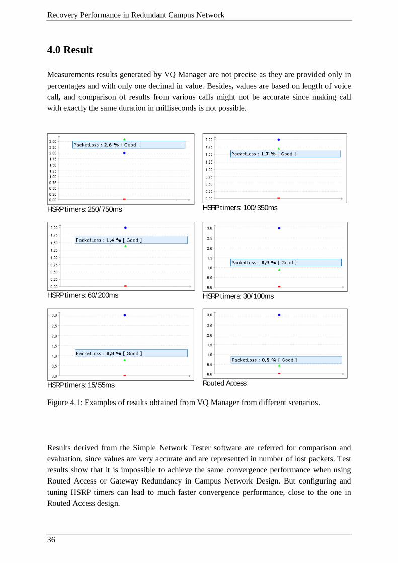
Measurements results generated by VQ Manager are not precise as they are provided only in percentages and with only one decimal in value. Besides, values are based on length of voice call, and comparison of results from various calls might not be accurate since making call with exactly the same duration in milliseconds is not possible.
HSRP timers: 250/750ms
HSRP timers: 100/350ms
HSRP timers: 60/200ms
HSRP timers: 30/100ms
HSRP timers: 15/55ms
Routed Access
Figure 4.1: Examples of results obtained from VQ Manager from different scenarios.
Results derived from the Simple Network Tester software are referred for comparison and evaluation, since values are very accurate and are represented in number of lost packets. Test results show that it is impossible to achieve the same convergence performance when using Routed Access or Gateway Redundancy in Campus Network Design. But configuring and tuning HSRP timers can lead to much faster convergence performance, close to the one in Routed Access design.

37
Protocol Hello/Hold Timers (ms) Failed Link Failed Node
Packet Loss Packet Loss (Min) (Max)
HSRP 250/750 Acc22 - Dist21 Dist21 31 36 HSRP 100/350 Acc22 - Dist21 Dist21 15 19 HSRP 60/200 Acc22 - Dist21 Dist21 9 12 HSRP 30/100 Acc22 - Dist21 Dist21 5 8 HSRP 15/55 Acc22 - Dist21 Dist21 5 6
EIGRP/OSPF Acc22 - Dist22 Dist22 2 5 Table 4.1: Comparison of packet loss in different scenarios
Figure 4.2: Comparison of packet loss in different scenarios
However, the factors such as hello packet generation affecting CPU load of the switch and the bandwidth consumption by these packets must be taken into consideration when implementing this design. In different companies, the bandwidth, recovery performance importance, number of VLANs on each distribution block, budget for network design and other issues vary and the choice of redundancy design will depend on these factors. For example, from tests, even though it is clear that exactly the same convergence performance is not achieved, there is still a possibility of keeping the minimum packet loss in the Default Gateway Redundancy scenario the same as the maximum packet loss in Routed Access one. It means that in some cases the approximate performance can be achieved by providing some configuration tunings. If this convergence performance differences are not crucial in production commercial costs can be saved by using Gateway Redundancy design as the Access switches do not need to be the expensive, advanced ones, such as multilayer switches, to provide routing as well. The general advantages and disadvantages of both scenarios are described in Table 4.2.

Recovery Performance in Redundant Campus Network
38
Default Gateway Redundancy Routed Access
Disadvantage: - non-deterministic, timer based convergence - extra CPU load as hello packets are generated Advantage - traditional non-expensive L2 switches
Advantage: - deterministic, non-timer based convergence - no extra CPU load as redundancy is provided by equal cost routes Disadvantage - advanced expensive multilayer switches
Table 4.2: Advantages and disadvantages of default gateway and routed access redundancy

39
5.0 Conclusion
The main goal of the thesis was to study the recovery performance of two redundancy scenarios in campus network design. By evaluating the test results from Default Gateway Redundancy and Routed Access scenarios, it can be concluded that both have their advantages and disadvantages which have to be taken into consideration while designing and configuring redundant campus network, or migrating from one design to another. Tests show that it is not possible to achieve the same deterministic convergence performance in Default Gateway design as it is provided by Routed Access, but fine tuning of timers will result in high fail-over recovery performance. Tuning the timers in Default Gateway Redundancy design has the disadvantage of increasing load on switch CPU as the frequency of hello packet generation is increased. Extra load on CPU does not occur in multilayer switches used in Routed Access design since redundancy is provided by equal cost routes, and is not timer-based. However, the big disadvantage of the Routed Access option is the requirement for expensive, advanced multilayer switches to support the routing functionality as well. And more are the switches that are needed in Access Layer segment of campus network, the greater is the expense of commercial costs.
The measurement results come from the tests performed in the lab environment. The network designed in the lab can be different from the one built in production. Hence, there will be other factors, such as load of the network and number of nodes to be taken into account while building the production network. However, to gain a general idea and for the purpose of comparison, the baseline of test results from the lab can be referred.
All these facts, trade-offs, advantages and disadvantages, must be considered by the network architect to make an optimal decision for implementing one or the other redundancy option in campus network.

Recovery Performance in Redundant Campus Network
40
6.0 References [1] Priscilla Oppenheimer. “Top-down Network Design, 2nd Edition”. Cisco Press. May
2004. [2] Cisco Systems, Inc. “Campus Network for High Availability Design Guide”. 2008. http://www.cisco.com/application/pdf/en/us/guest/netsol/ns431/c649/ccmigration_091
86a008093b876.pdf [3] Douglas Alger. “Build the Best Data Center Facility for Your Business”. Cisco Press.
June 2005. [4] Jeff Doyle, Jennifer Carroll.“Routing TCP/IP , Volume 1, 2nd Edition”. Cisco Press.
October 2005. [5] Cisco Systems, Inc. “Campus Network for High Availability Design Guide – Routed
Access Layer using OSPF”. 2007. http://www.cisco.com/application/pdf/en/us/guest/netsol/ns432/c649/ccmigration_091
86a0080811468.pdf [6] Sam Halabi, Bill Cormier. “Enterprise Network Design Patterns: High Availability”.
Sun BluePrints™ OnLine. December 2003. www.sun.com/blueprints/1203/817-4683.pdf [7] Cisco Systems, Inc. Campus Network for High Availability Design Guide – Routed
Access Layer using EIGRP”. 2005 http://www.cisco.com/application/pdf/en/us/guest/netsol/ns432/c649/ccmigration_091
86a00805fccbf.pdf [8] J. Moy, “The OSPF Specification”, RFC1131. 1989. http://www.ietf.org/rfc/rfc1131 [9] J. Moy, “OSPF Version 2”. RFC2328. 1998. http://www.ietf.org/rfc/rfc2328 [10] J. Rosenberg. “SIP: Session Initiation Protocol”. RFC3261. 2002. http://www.ietf.org/rfc/rfc3261 [11] Cisco Systems, Inc. “What is VRRP?”. Document ID: 7210. 2006. http://www.cisco.com/en/US/products/hw/vpndevc/ps2284/products_tech_note09186a
0080094490.shtml [12] R. Hinden, Ed. “Virtual Router Redundancy Protocol (VRRP)”. RFC3768. 2004. http://www.ietf.org/rfc/rfc3768 [13] Cisco Systems, Inc. “Troubleshooting hissing and static”. Document ID 22388. 2006.
http://www.cisco.com/en/US/tech/tk652/tk698/technologies_tech_note09186a00800a9982.shtml
[14] T. Li, B. Cole, P. Morton, D. Li, “Hot Standby Router Protocol (HSRP)”, RFC2281.
http://www.ietf.org/rfc/rfc2281 .

41
[15] Cisco Systems, Inc. “Cisco GLBP Load Balancing Options (Data sheet)”. 2005. http://www.cisco.com/en/US/prod/collateral/iosswrel/ps6537/ps6554/ps6600/product_data_sheet0900aecd803a546c.html.
[16] D. Thaler. “Multi-Link Subnet Issues”. RFC4903. 2007. http://www.ietf.org/rfc/rfc4903
Recovery Performance in Redundant Campus Network
42
7.0 Appendix 7.1 Default Gateway Redundancy Scenario - Switch Configurations 7.1.1 Switch - Acc11 ! version 12.2 no service pad service timestamps debug uptime service timestamps log uptime no service password-encryption ! hostname acc11 ! ! no aaa new-model ip subnet-zero ! ! ! ! no file verify auto ! spanning-tree mode rapid-pvst spanning-tree loopguard default spanning-tree portfast default spanning-tree extend system-id ! vlan internal allocation policy ascending ! ! interface FastEthernet0/1 ! interface FastEthernet0/2 ! interface FastEthernet0/3 ! interface FastEthernet0/4 ! interface FastEthernet0/5 ! interface FastEthernet0/6 ! interface FastEthernet0/7 ! interface FastEthernet0/8 ! interface FastEthernet0/9 ! interface FastEthernet0/10 description Uplink to Dist11 switchport trunk encapsulation dot1q switchport mode trunk switchport nonegotiate mls qos trust dscp ! interface FastEthernet0/11 description Uplink to Dist12 switchport trunk encapsulation dot1q switchport mode trunk

43
switchport nonegotiate mls qos trust dscp ! interface FastEthernet0/12 ! interface FastEthernet0/13 ! interface FastEthernet0/14 ! interface FastEthernet0/15 switchport access vlan 15 switchport mode access ! interface FastEthernet0/16 ! interface FastEthernet0/17 ! interface FastEthernet0/18 ! interface FastEthernet0/19 ! interface FastEthernet0/20 ! interface FastEthernet0/21 ! interface FastEthernet0/22 ! interface FastEthernet0/23 ! interface FastEthernet0/24 ! interface GigabitEthernet0/1 ! interface GigabitEthernet0/2 ! interface Vlan1 no ip address no ip route-cache shutdown ! ip classless no ip http server ! ! ! control-plane ! ! line con 0 line vty 5 15 ! end 7.1.2 Switch - Acc12 ! version 12.2 no service pad service timestamps debug uptime service timestamps log uptime no service password-encryption !
Recovery Performance in Redundant Campus Network
44
hostname acc12 ! ! no aaa new-model ip subnet-zero ! ! ! ! no file verify auto ! spanning-tree mode rapid-pvst spanning-tree loopguard default spanning-tree portfast default spanning-tree extend system-id ! vlan internal allocation policy ascending ! ! interface FastEthernet0/1 ! interface FastEthernet0/2 ! interface FastEthernet0/3 ! interface FastEthernet0/4 ! interface FastEthernet0/5 ! interface FastEthernet0/6 ! interface FastEthernet0/7 ! interface FastEthernet0/8 ! interface FastEthernet0/9 ! interface FastEthernet0/10 description Uplink to Dist12 switchport trunk encapsulation dot1q switchport mode trunk switchport nonegotiate mls qos trust dscp ! interface FastEthernet0/11 description Uplink to Dist11 switchport trunk encapsulation dot1q switchport mode trunk switchport nonegotiate mls qos trust dscp ! interface FastEthernet0/12 ! interface FastEthernet0/13 ! interface FastEthernet0/14 ! interface FastEthernet0/15 switchport access vlan 100 switchport mode access ! interface FastEthernet0/16 ! interface FastEthernet0/17
45
! interface FastEthernet0/18 ! interface FastEthernet0/19 ! interface FastEthernet0/20 ! interface FastEthernet0/21 ! interface FastEthernet0/22 ! interface FastEthernet0/23 ! interface FastEthernet0/24 ! interface GigabitEthernet0/1 ! interface GigabitEthernet0/2 ! interface Vlan1 no ip address no ip route-cache no ip mroute-cache shutdown ! ip classless no ip http server ! ! ! control-plane ! ! line con 0 line vty 0 4 no login line vty 5 15 no login ! end 7.1.3 Switch - Dist11 ! version 12.2 no service pad service timestamps debug uptime service timestamps log uptime no service password-encryption ! hostname dist11 ! ! no aaa new-model ip subnet-zero ip routing ! ! ! ! ! !

Recovery Performance in Redundant Campus Network
46
no file verify auto ! spanning-tree mode rapid-pvst spanning-tree loopguard default spanning-tree extend system-id ! vlan internal allocation policy ascending ! ! interface FastEthernet0/1 description Link to Dist12 no switchport ip address 10.0.3.0 255.255.255.254 ip ospf dead-interval minimal hello-multiplier 4 carrier-delay msec 0 mls qos trust dscp ! interface FastEthernet0/2 description Uplink to Core1 no switchport ip address 10.1.1.0 255.255.255.254 ip ospf dead-interval minimal hello-multiplier 4 carrier-delay msec 0 mls qos trust dscp ! interface FastEthernet0/3 description Uplink to Core2 no switchport ip address 10.1.1.2 255.255.255.254 ip ospf dead-interval minimal hello-multiplier 4 carrier-delay msec 0 mls qos trust dscp ! interface FastEthernet0/4 ! interface FastEthernet0/5 ! interface FastEthernet0/6 ! interface FastEthernet0/7 ! interface FastEthernet0/8 ! interface FastEthernet0/9 ! interace FastEthernet0/10 description Downlink to Acc11 Switch switchport trunk encapsulation dot1q switchport mode trunk switchport nonegotiate mls qos trust dscp ! interface FastEthernet0/11 description Downlink to Acc12 Switch switchport trunk encapsulation dot1q switchport mode trunk switchport nonegotiate mls qos trust dscp ! interface FastEthernet0/12 ! interface FastEthernet0/13 ! interface FastEthernet0/14

47
! interface FastEthernet0/15 ! interface FastEthernet0/16 ! interface FastEthernet0/17 ! interface FastEthernet0/18 ! interface FastEthernet0/19 ! interface FastEthernet0/20 ! interface FastEthernet0/21 ! interface FastEthernet0/22 ! interface FastEthernet0/23 ! interface FastEthernet0/24 ! interface GigabitEthernet0/1 ! interface GigabitEthernet0/2 ! interface Vlan1 no ip address shutdown ! interface Vlan10 ip address 10.0.10.5 255.255.255.0 standby 1 ip 10.0.10.1 standby 1 timers msec 50 msec 200 standby 1 priority 150 standby 1 preempt delay minimum 180 ! interface Vlan15 ip address 10.0.15.5 255.255.255.0 standby 15 ip 10.0.15.1 standby 15 timers msec 50 msec 200 ! interface Vlan100 ip address 10.0.100.5 255.255.255.0 standby 100 ip 10.0.100.1 standby 100 timers msec 50 msec 200 standby 100 priority 150 standby 100 preempt delay minimum 180 ! interface Vlan150 ip address 10.0.150.5 255.255.255.0 standby 15 timers msec 50 msec 200 standby 150 ip 10.0.150.1 standby 150 timers msec 50 msec 200 ! router ospf 10 ispf log-adjacency-changes area 1 stub area 1 range 10.0.0.0 255.255.0.0 cost 10 timers throttle spf 10 300 5000 timers throttle lsa all 10 300 5000 timers lsa arrival 100 network 10.0.0.0 0.0.255.255 area 1 network 10.1.0.0 0.0.255.255 area 0

Recovery Performance in Redundant Campus Network
48
! ip classless no ip http server ip http secure-server ! ! ! control-plane ! ! line con 0 line vty 5 15 ! end 7.1.4 Switch - Dist12 ! version 12.2 no service pad service timestamps debug uptime service timestamps log uptime no service password-encryption ! hostname dist12 ! ! no aaa new-model ip subnet-zero ip routing ! ! ! ! ! ! no file verify auto ! spanning-tree mode rapid-pvst spanning-tree loopguard default spanning-tree extend system-id ! vlan internal allocation policy ascending ! ! interface FastEthernet0/1 description Link to Dist11 no switchport ip address 10.0.3.1 255.255.255.254 ip ospf dead-interval minimal hello-multiplier 4 carrier-delay msec 0 mls qos trust dscp ! interface FastEthernet0/2 description Uplink to Core2 no switchport ip address 10.1.1.4 255.255.255.254 ip ospf dead-interval minimal hello-multiplier 4 carrier-delay msec 0 mls qos trust dscp ! interface FastEthernet0/3

49
description Uplink to Core1 no switchport ip address 10.1.1.6 255.255.255.254 ip ospf dead-interval minimal hello-multiplier 4 carrier-delay msec 0 mls qos trust dscp ! interface FastEthernet0/4 ! interface FastEthernet0/5 ! interface FastEthernet0/6 ! interface FastEthernet0/7 ! interface FastEthernet0/8 ! interface FastEthernet0/9 ! interface FastEthernet0/10 description Downlink to Acc12 Switch switchport trunk encapsulation dot1q switchport mode trunk switchport nonegotiate mls qos trust dscp ! interface FastEthernet0/11 description Downlink to Acc11 Switch switchport trunk encapsulation dot1q switchport mode trunk switchport nonegotiate mls qos trust dscp ! interface FastEthernet0/12 ! interface FastEthernet0/13 ! interface FastEthernet0/14 ! interface FastEthernet0/15 ! interface FastEthernet0/16 ! interface FastEthernet0/17 ! interface FastEthernet0/18 ! interface FastEthernet0/19 ! interface FastEthernet0/20 ! interface FastEthernet0/21 ! interface FastEthernet0/22 ! interface FastEthernet0/23 ! interface FastEthernet0/24 ! interface GigabitEthernet0/1 ! interface GigabitEthernet0/2 ! interface Vlan1

Recovery Performance in Redundant Campus Network
50
no ip address shutdown ! interface Vlan10 ip address 10.0.10.10 255.255.255.0 standby 1 ip 10.0.10.1 standby 1 timers msec 50 msec 200 ! interface Vlan15 ip address 10.0.15.10 255.255.255.0 standby 15 ip 10.0.15.1 standby 15 timers msec 50 msec 200 standby 15 priority 150 standby 15 preempt delay minimum 180 ! interface Vlan100 ip address 10.0.100.10 255.255.255.0 standby 100 ip 10.0.100.1 standby 100 timers msec 50 msec 200 ! interface Vlan150 ip address 10.0.150.10 255.255.255.0 standby 150 ip 10.0.150.1 standby 150 timers msec 50 msec 200 standby 150 priority 150 standby 150 preempt delay minimum 180 ! router ospf 10 ispf log-adjacency-changes area 1 stub area 1 range 10.0.0.0 255.255.0.0 cost 10 timers throttle spf 10 300 5000 timers throttle lsa all 10 300 5000 timers lsa arrival 100 network 10.0.0.0 0.0.255.255 area 1 network 10.1.0.0 0.0.255.255 area 0 ! ip classless no ip http server ip http secure-server ! ! ! control-plane ! ! line con 0 line vty 5 15 ! 7.1.5 Switch - Core1 ! version 12.2 no service pad service timestamps debug uptime service timestamps log uptime no service password-encryption ! hostname core1 !

51
boot-start-marker boot-end-marker ! ! no aaa new-model system mtu routing 1500 ip subnet-zero ip routing ! ! ! spanning-tree mode rapid-pvst spanning-tree etherchannel guard misconfig spanning-tree extend system-id ! vlan internal allocation policy ascending ! ! ! interface FastEthernet0/1 description Link to Core2 no switchport ip address 10.3.0.0 255.255.255.254 ip ospf dead-interval minimal hello-multiplier 4 carrier-delay msec 0 mls qos trust dscp ! interface FastEthernet0/2 description Downlink to Dist11 no switchport ip address 10.1.1.1 255.255.255.254 ip ospf dead-interval minimal hello-multiplier 4 carrier-delay msec 0 mls qos trust dscp ! interface FastEthernet0/3 description Downlink to Dist12 no switchport ip address 10.1.1.7 255.255.255.254 ip ospf dead-interval minimal hello-multiplier 4 carrier-delay msec 0 mls qos trust dscp ! interface FastEthernet0/4 description Downlink to Dist21 no switchport ip address 10.2.1.3 255.255.255.254 ip ospf dead-interval minimal hello-multiplier 4 carrier-delay msec 0 mls qos trust dscp ! interface FastEthernet0/5 description Downlink to Dist22 no switchport ip address 10.2.1.5 255.255.255.254 ip ospf dead-interval minimal hello-multiplier 4 carrier-delay msec 0 mls qos trust dscp ! interface FastEthernet0/6 switchport mode dynamic desirable ! interface FastEthernet0/7 switchport mode dynamic desirable

Recovery Performance in Redundant Campus Network
52
! interface FastEthernet0/8 switchport mode dynamic desirable ! interface FastEthernet0/9 switchport mode dynamic desirable ! interface FastEthernet0/10 no switchport ip address 10.4.0.1 255.255.255.254 ip ospf dead-interval minimal hello-multiplier 4 carrier-delay msec 0 mls qos trust dscp ! interface FastEthernet0/11 switchport mode dynamic desirable ! interface FastEthernet0/12 switchport mode dynamic desirable ! interface FastEthernet0/13 switchport mode dynamic desirable ! interface FastEthernet0/14 switchport mode dynamic desirable ! interface FastEthernet0/15 switchport mode dynamic desirable ! interface FastEthernet0/16 switchport mode dynamic desirable ! interface FastEthernet0/17 switchport mode dynamic desirable ! interface FastEthernet0/18 switchport mode dynamic desirable ! interface FastEthernet0/19 switchport mode dynamic desirable ! interface FastEthernet0/20 switchport mode dynamic desirable ! interface FastEthernet0/21 switchport mode dynamic desirable ! interface FastEthernet0/22 switchport mode dynamic desirable ! interface FastEthernet0/23 switchport mode dynamic desirable ! interface FastEthernet0/24 switchport mode dynamic desirable ! interface GigabitEthernet0/1 switchport mode dynamic desirable ! interface GigabitEthernet0/2 switchport mode dynamic desirable ! interface Vlan1 no ip address
53
shutdown ! router ospf 10 log-adjacency-changes timers throttle spf 10 300 5000 timers throttle lsa all 10 300 5000 network 10.0.0.0 0.255.255.255 area 0 ! ip classless ip http server ip http secure-server ! ! ! control-plane ! ! line con 0 line vty 5 15 ! end 7.1.6 Switch – Acc21 ! version 12.2 no service pad service timestamps debug uptime service timestamps log uptime no service password-encryption ! hostname acc21 ! ! no aaa new-model system mtu routing 1500 vtp mode transparent ip subnet-zero ! ! ! ! no file verify auto ! spanning-tree mode rapid-pvst spanning-tree loopguard default spanning-tree portfast default spanning-tree extend system-id ! vlan internal allocation policy ascending ! vlan 200 name vlan200 ! vlan 250 name vlan250 ! ! interface FastEthernet0/1 ! interface FastEthernet0/2 !

Recovery Performance in Redundant Campus Network
54
interface FastEthernet0/3 ! interface FastEthernet0/4 ! interface FastEthernet0/5 ! interface FastEthernet0/6 ! interface FastEthernet0/7 ! interface FastEthernet0/8 ! interface FastEthernet0/9 ! interface FastEthernet0/10 description Uplink to Dist21 switchport trunk encapsulation dot1q switchport mode trunk switchport nonegotiate mls qos trust dscp ! interface FastEthernet0/11 description Uplink to Dist22 switchport trunk encapsulation dot1q switchport mode trunk switchport nonegotiate mls qos trust dscp ! interface FastEthernet0/12 ! interface FastEthernet0/13 ! interface FastEthernet0/14 ! interface FastEthernet0/15 ! interface FastEthernet0/16 ! interface FastEthernet0/17 ! interface FastEthernet0/18 ! interface FastEthernet0/19 ! interface FastEthernet0/20 ! interface FastEthernet0/21 switchport mode access ! interface FastEthernet0/22 ! interface FastEthernet0/23 ! interface FastEthernet0/24 ! interface GigabitEthernet0/1 ! interface GigabitEthernet0/2 ! interface Vlan1 no ip address no ip route-cache shutdown !

55
ip classless ip http server ! ! ! control-plane ! ! line con 0 line vty 5 15 ! end 7.1.7 Switch – Acc22 ! version 12.2 no service pad service timestamps debug uptime service timestamps log uptime no service password-encryption ! hostname acc22 ! ! no aaa new-model vtp mode transparent ip subnet-zero ! ! ! no file verify auto ! spanning-tree mode rapid-pvst spanning-tree loopguard default spanning-tree portfast default spanning-tree extend system-id ! vlan internal allocation policy ascending ! vlan 110 name vlan110 ! vlan 120 name vlan120 ! ! interface FastEthernet0/1 switchport access vlan 110 switchport mode access ! interface FastEthernet0/2 ! interface FastEthernet0/3 ! interface FastEthernet0/4 ! interface FastEthernet0/5 ! interface FastEthernet0/6 !

Recovery Performance in Redundant Campus Network
56
interface FastEthernet0/7 ! interface FastEthernet0/8 ! interface FastEthernet0/9 ! interface FastEthernet0/10 description Uplink to Dist22 switchport trunk encapsulation dot1q switchport mode trunk switchport nonegotiate mls qos trust dscp ! interface FastEthernet0/11 description Uplink to Dist21 switchport trunk encapsulation dot1q switchport mode trunk switchport nonegotiate mls qos trust dscp ! interface FastEthernet0/12 ! interface FastEthernet0/13 ! interface FastEthernet0/14 ! interface FastEthernet0/15 ! interface FastEthernet0/16 ! interface FastEthernet0/17 ! interface FastEthernet0/18 ! interface FastEthernet0/19 ! interface FastEthernet0/20 ! interface FastEthernet0/21 ! interface FastEthernet0/22 ! interface FastEthernet0/23 ! interface FastEthernet0/24 ! interface GigabitEthernet0/1 ! interface GigabitEthernet0/2 ! interface Vlan1 no ip address no ip route-cache ! ip classless ip http server ! ! control-plane ! ! line con 0 line vty 5 15 !

57
end 7.1.8 Switch – Dist21 ! version 12.2 no service pad service timestamps debug uptime service timestamps log uptime no service password-encryption ! hostname dist21 ! ! no aaa new-model ip subnet-zero ip routing ! ! ! ! no file verify auto ! spanning-tree mode rapid-pvst spanning-tree loopguard default spanning-tree extend system-id ! vlan internal allocation policy ascending ! ! interface FastEthernet0/1 description Link to Dist22 no switchport ip address 10.10.3.0 255.255.255.254 ip ospf dead-interval minimal hello-multiplier 4 carrier-delay msec 0 mls qos trust dscp ! interface FastEthernet0/2 ! interface FastEthernet0/3 ! interface FastEthernet0/4 description Uplink to Core1 no switchport ip address 10.2.1.2 255.255.255.254 ip ospf dead-interval minimal hello-multiplier 4 carrier-delay msec 0 mls qos trust dscp ! interface FastEthernet0/5 description Uplink to Core2 no switchport ip address 10.2.1.0 255.255.255.254 ip ospf dead-interval minimal hello-multiplier 4 carrier-delay msec 0 mls qos trust dscp ! interface FastEthernet0/6 ! interface FastEthernet0/7 ! interface FastEthernet0/8

Recovery Performance in Redundant Campus Network
58
! interface FastEthernet0/9 ! interface FastEthernet0/10 description Downlink to Acc21 Switch switchport trunk encapsulation dot1q switchport mode trunk switchport nonegotiate mls qos trust dscp ! interface FastEthernet0/11 description Downlink to Acc22 Switch switchport trunk encapsulation dot1q switchport mode trunk switchport nonegotiate mls qos trust dscp ! interface FastEthernet0/12 ! interface FastEthernet0/13 ! interface FastEthernet0/14 ! interface FastEthernet0/15 ! interface FastEthernet0/16 ! interface FastEthernet0/17 ! interface FastEthernet0/18 ! interface FastEthernet0/19 ! interface FastEthernet0/20 ! interface FastEthernet0/21 ! interface FastEthernet0/22 ! interface FastEthernet0/23 ! interface FastEthernet0/24 ! interface GigabitEthernet0/1 ! interface GigabitEthernet0/2 ! interface Vlan1 no ip address shutdown ! interface Vlan110 ip address 10.10.110.5 255.255.255.0 standby version 2 standby 110 ip 10.10.110.1 standby 110 timers msec 100 msec 350 standby 110 priority 150 standby 110 preempt delay minimum 180 ! interface Vlan120 ip address 10.10.120.5 255.255.255.0 standby version 2 standby 120 ip 10.10.120.1 standby 120 timers msec 100 msec 350

59
! interface Vlan200 ip address 10.10.200.5 255.255.255.0 standby version 2 standby 200 ip 10.10.200.1 standby 200 timers msec 100 msec 350 ! interface Vlan250 ip address 10.10.250.5 255.255.255.0 standby version 2 standby 250 ip 10.10.250.1 standby 250 timers msec 100 msec 350 standby 250 priority 150 standby 250 preempt delay minimum 180 ! router ospf 10 ispf log-adjacency-changes area 2 stub area 2 range 10.10.0.0 255.255.0.0 cost 10 timers throttle spf 10 300 5000 timers throttle lsa all 10 300 5000 timers lsa arrival 100 network 10.2.0.0 0.0.255.255 area 0 network 10.10.0.0 0.0.255.255 area 2 ! ip classless ip http server ! ! ! control-plane ! ! line con 0 line vty 0 4 no login line vty 5 15 no login ! end 7.1.9 Switch – Dist22 ! version 12.2 no service pad service timestamps debug uptime service timestamps log uptime no service password-encryption ! hostname dist22 ! ! no aaa new-model system mtu routing 1500 ip subnet-zero ip routing ! ! ! !

Recovery Performance in Redundant Campus Network
60
no file verify auto ! spanning-tree mode rapid-pvst spanning-tree loopguard default spanning-tree extend system-id ! vlan internal allocation policy ascending ! ! interface FastEthernet0/1 description Link to Dist21 no switchport ip address 10.10.3.1 255.255.255.254 ip ospf dead-interval minimal hello-multiplier 4 carrier-delay msec 0 mls qos trust dscp ! interface FastEthernet0/2 ! interface FastEthernet0/3 ! interface FastEthernet0/4 description Uplink to Core2 no switchport ip address 10.2.1.6 255.255.255.254 ip ospf dead-interval minimal hello-multiplier 4 carrier-delay msec 0 mls qos trust dscp ! interface FastEthernet0/5 description Uplink to Core1 no switchport ip address 10.2.1.4 255.255.255.254 ip ospf dead-interval minimal hello-multiplier 4 carrier-delay msec 0 mls qos trust dStandby -> Activescp ! interface FastEthernet0/6 ! interface FastEthernet0/7 ! interface FastEthernet0/8 ! interface FastEthernet0/9 ! interface FastEthernet0/10 description Downlink to Acc22 Switch switchport trunk encapsulation dot1q switchport mode trunk switchport nonegotiate mls qos trust dscp ! interface FastEthernet0/11 description Downlink to Acc21 Switch switchport trunk encapsulation dot1q switchport mode trunk switchport nonegotiate mls qos trust dscp ! interface FastEthernet0/12 ! interface FastEthernet0/13 ! interface FastEthernet0/14

61
! interface FastEthernet0/15 ! interface FastEthernet0/16 ! interface FastEthernet0/17 ! interface FastEthernet0/18 ! interface FastEthernet0/19 ! interface FastEthernet0/20 ! interface FastEthernet0/21 ! interface FastEthernet0/22 ! interface FastEthernet0/23 ! interface FastEthernet0/24 ! interface GigabitEthernet0/1 ! interface GigabitEthernet0/2 ! interface Vlan1 no ip address shutdown ! interface Vlan110 ip address 10.10.110.10 255.255.255.0 standby 110 ip 10.10.110.1 standby 110 timers msec 100 msec 350 ! interface Vlan120 ip address 10.10.120.10 255.255.255.0 standby 120 ip 10.10.120.1 standby 120 timers msec 100 msec 350 standby 120 priority 150 standby 120 preempt delay minimum 180 ! interface Vlan200 ip address 10.10.200.10 255.255.255.0 standby 200 ip 10.10.200.1 standby 200 timers msec 100 msec 350 standby 200 priority 150 standby 200 preempt delay minimum 180 ! interface Vlan250 ip address 10.10.250.10 255.255.255.0 standby 250 ip 10.10.250.1 standby 250 timers msec 100 msec 350 ! router ospf 10 ispf log-adjacency-changes area 2 stub area 2 range 10.10.0.0 255.255.0.0 cost 10 timers throttle spf 10 300 5000 timers throttle lsa all 10 300 5000 timers lsa arrival 100 network 10.2.0.0 0.0.255.255 area 0 network 10.10.0.0 0.0.255.255 area 2 !

Recovery Performance in Redundant Campus Network
62
ip classless ip http server ! ! control-plane ! ! line con 0 line vty 0 4 login line vty 5 15 login ! end 7.1.10 Switch – Core2 ! version 12.2 no service pad service timestamps debug uptime service timestamps log uptime no service password-encryption ! hostname core2 ! ! no aaa new-model vtp mode transparent ip subnet-zero ip routing ! ! ! ! ! ! no file verify auto ! spanning-tree mode rapid-pvst spanning-tree extend system-id ! vlan internal allocation policy ascending ! ! interface FastEthernet0/1 description Link to Core1 no switchport ip address 10.3.0.1 255.255.255.254 ip ospf dead-interval minimal hello-multiplier 4 carrier-delay msec 0 mls qos trust dscp ! interface FastEthernet0/2 description Downlink to Dist12 no switchport ip address 10.1.1.5 255.255.255.254 ip ospf dead-interval minimal hello-multiplier 4 carrier-delay msec 0 mls qos trust dscp ! interface FastEthernet0/3

63
description Downlink to Dist11 no switchport ip address 10.1.1.3 255.255.255.254 ip ospf dead-interval minimal hello-multiplier 4 carrier-delay msec 0 mls qos trust dscp ! interface FastEthernet0/4 description Downlink to Dist22 no switchport ip address 10.2.1.7 255.255.255.254 ip ospf dead-interval minimal hello-multiplier 4 carrier-delay msec 0 mls qos trust dscp ! interface FastEthernet0/5 description Downlink to Dist21 no switchport ip address 10.2.1.1 255.255.255.254 ip ospf dead-interval minimal hello-multiplier 4 carrier-delay msec 0 mls qos trust dscp ! interface FastEthernet0/6 switchport mode dynamic desirable ! interface FastEthernet0/7 switchport mode dynamic desirable ! interface FastEthernet0/8 switchport mode dynamic desirable ! interface FastEthernet0/9 switchport mode dynamic desirable ! interface FastEthernet0/10 switchport mode dynamic desirable ! interface FastEthernet0/11 switchport mode dynamic desirable ! interface FastEthernet0/12 switchport mode dynamic desirable ! interface FastEthernet0/13 switchport mode dynamic desirable ! interface FastEthernet0/14 switchport mode dynamic desirable ! interface FastEthernet0/15 switchport mode dynamic desirable ! interface FastEthernet0/16 switchport mode dynamic desirable ! interface FastEthernet0/17 switchport mode dynamic desirable ! interface FastEthernet0/18 switchport mode dynamic desirable ! interface FastEthernet0/19 switchport mode dynamic desirable
Recovery Performance in Redundant Campus Network
64
! interface FastEthernet0/20 switchport mode dynamic desirable ! interface FastEthernet0/21 switchport mode dynamic desirable ! interface FastEthernet0/22 switchport mode dynamic desirable ! interface FastEthernet0/23 switchport mode dynamic desirable ! interface FastEthernet0/24 switchport mode dynamic desirable ! interface GigabitEthernet0/1 switchport mode dynamic desirable ! interface GigabitEthernet0/2 switchport mode dynamic desirable ! interface Vlan1 no ip address shutdown ! router ospf 10 log-adjacency-changes timers throttle spf 10 300 5000 timers throttle lsa all 10 300 5000 network 10.0.0.0 0.255.255.255 area 0 ! ip classless ip http server ip http secure-server ! ! ! control-plane ! ! line con 0 line vty 5 15 ! end 7.2 Routed Access Scenario (OSPF) - Switch Configurations 7.2.1 Switch – Acc11 ! version 12.2 no service pad service timestamps debug uptime service timestamps log uptime no service password-encryption ! hostname acc11 ! !

65
no aaa new-model system mtu routing 1500 ip subnet-zero ip routing ! ! ! ! no file verify auto ! spanning-tree mode rapid-pvst spanning-tree loopguard default spanning-tree portfast default spanning-tree extend system-id ! vlan internal allocation policy ascending ! ! interface FastEthernet0/1 ! interface FastEthernet0/2 ! interface FastEthernet0/3 ! interface FastEthernet0/4 ! interface FastEthernet0/5 ! interface FastEthernet0/6 ! interface FastEthernet0/7 ! interface FastEthernet0/8 ! interface FastEthernet0/9 ! interface FastEthernet0/10 description Uplink to Dist11 no switchport ip address 10.0.1.1 255.255.255.254 ip ospf dead-interval minimal hello-multiplier 4 carrier-delay msec 0 mls qos trust dscp ! interface FastEthernet0/11 description Uplink to Dist12 no switchport ip address 10.0.2.3 255.255.255.254 ip ospf dead-interval minimal hello-multiplier 4 carrier-delay msec 0 mls qos trust dscp ! interface FastEthernet0/12 ! interface FastEthernet0/13 ! interface FastEthernet0/14 ! interface FastEthernet0/15 switchport access vlan 15 switchport mode access ! interface FastEthernet0/16 !

Recovery Performance in Redundant Campus Network
66
interface FastEthernet0/17 ! interface FastEthernet0/18 ! interface FastEthernet0/19 ! interface FastEthernet0/20 ! interface FastEthernet0/21 ! interface FastEthernet0/22 ! interface FastEthernet0/23 ! interface FastEthernet0/24 ! interface GigabitEthernet0/1 ! interface GigabitEthernet0/2 ! interface Vlan1 no ip address shutdown ! interface Vlan10 ip address 10.0.10.1 255.255.255.0 ! interface Vlan15 ip address 10.0.15.1 255.255.255.0 ! router ospf 10 ispf log-adjacency-changes area 1 stub no-summary timers throttle spf 10 300 5000 timers throttle lsa all 10 300 5000 timers lsa arrival 100 network 10.0.0.0 0.0.255.255 area 1 ! ip classless no ip http server ! ! ! control-plane ! ! line con 0 logging synchronous line vty 0 4 login line vty 5 15 login ! end 7.2.2 Switch – Acc12 ! version 12.2 no service pad service timestamps debug uptime

67
service timestamps log uptime no service password-encryption ! hostname acc12 ! ! no aaa new-model system mtu routing 1500 ip subnet-zero ip routing ! ! ! no file verify auto ! spanning-tree mode rapid-pvst spanning-tree loopguard default spanning-tree portfast default spanning-tree extend system-id ! vlan internal allocation policy ascending ! ! interface FastEthernet0/1 ! interface FastEthernet0/2 ! interface FastEthernet0/3 ! interface FastEthernet0/4 ! interface FastEthernet0/5 ! interface FastEthernet0/6 ! interface FastEthernet0/7 ! interface FastEthernet0/8 ! interface FastEthernet0/9 ! interface FastEthernet0/10 description Uplink to Dist12 no switchport ip address 10.0.2.1 255.255.255.254 ip ospf dead-interval minimal hello-multiplier 4 carrier-delay msec 0 mls qos trust dscp ! interface FastEthernet0/11 description Uplink to Dist11 no switchport ip address 10.0.1.3 255.255.255.254 ip ospf dead-interval minimal hello-multiplier 4 carrier-delay msec 0 mls qos trust dscp ! interface FastEthernet0/12 ! interface FastEthernet0/13 ! interface FastEthernet0/14 ! interface FastEthernet0/15

Recovery Performance in Redundant Campus Network
68
! interface FastEthernet0/16 ! interface FastEthernet0/17 ! interface FastEthernet0/18 ! interface FastEthernet0/19 ! interface FastEthernet0/20 ! interface FastEthernet0/21 ! interface FastEthernet0/22 ! interface FastEthernet0/23 ! interface FastEthernet0/24 ! interface GigabitEthernet0/1 ! interface GigabitEthernet0/2 ! interface Vlan1 no ip address shutdown ! interface Vlan100 ip address 10.0.100.1 255.255.255.0 ! interface Vlan150 ip address 10.0.150.1 255.255.255.0 ! router ospf 10 ispf log-adjacency-changes area 1 stub timers throttle spf 10 300 5000 timers throttle lsa all 10 300 5000 timers lsa arrival 100 network 10.0.0.0 0.0.255.255 area 1 ! ip classless no ip http server ! ! ! control-plane ! ! ! line con 0 logging synchronous line vty 0 4 login line vty 5 15 login ! end
69
7.2.3 Switch – Dist11 ! version 12.2 no service pad service timestamps debug uptime service timestamps log uptime no service password-encryption ! hostname dist11 ! ! no aaa new-model ip subnet-zero ip routing ! ! ! no file verify auto ! spanning-tree mode rapid-pvst spanning-tree loopguard default spanning-tree extend system-id ! vlan internal allocation policy ascending ! ! interface FastEthernet0/1 description Link to Dist12 no switchport ip address 10.0.3.0 255.255.255.254 ip ospf dead-interval minimal hello-multiplier 4 carrier-delay msec 0 mls qos trust dscp ! interface FastEthernet0/2 description Uplink to Core1 no switchport ip address 10.1.1.0 255.255.255.254 ip ospf dead-interval minimal hello-multiplier 4 carrier-delay msec 0 mls qos trust dscp ! interface FastEthernet0/3 description Uplink to Core2 no switchport ip address 10.1.1.2 255.255.255.254 ip ospf dead-interval minimal hello-multiplier 4 carrier-delay msec 0 mls qos trust dscp ! interface FastEthernet0/4 ! interface FastEthernet0/5 ! interface FastEthernet0/6 ! interface FastEthernet0/7 ! interface FastEthernet0/8 ! interface FastEthernet0/9 !

Recovery Performance in Redundant Campus Network
70
interface FastEthernet0/10 description Downlink to Acc11 Switch no switchport ip address 10.0.1.0 255.255.255.254 ip ospf dead-interval minimal hello-multiplier 4 ip ospf priority 255 carrier-delay msec 0 mls qos trust dscp ! interface FastEthernet0/11 description Downlink to Acc12 Switch no switchport ip address 10.0.1.2 255.255.255.254 ip ospf dead-interval minimal hello-multiplier 4 ip ospf priority 255 carrier-delay msec 0 mls qos trust dscp ! interface FastEthernet0/12 ! interface FastEthernet0/13 ! interface FastEthernet0/14 ! interface FastEthernet0/15 ! interface FastEthernet0/16 ! interface FastEthernet0/17 ! interface FastEthernet0/18 ! interface FastEthernet0/19 ! interface FastEthernet0/20 ! interface FastEthernet0/21 ! interface FastEthernet0/22 ! interface FastEthernet0/23 ! interface FastEthernet0/24 ! interface GigabitEthernet0/1 ! interface GigabitEthernet0/2 ! interface Vlan1 no ip address shutdown ! router ospf 10 ispf log-adjacency-changes area 1 stub area 1 range 10.0.0.0 255.255.0.0 cost 10 timers throttle spf 10 300 5000 timers throttle lsa all 10 300 5000 timers lsa arrival 100 network 10.0.0.0 0.0.255.255 area 1 network 10.1.0.0 0.0.255.255 area 0 ! ip classless

71
no ip http server ! ! ! control-plane ! ! line con 0 line vty 5 15 ! end 7.2.4 Switch – Dist12 ! version 12.2 no service pad service timestamps debug uptime service timestamps log uptime no service password-encryption ! hostname dist12 ! ! no aaa new-model ip subnet-zero ip routing ! ! ! ! no file verify auto ! spanning-tree mode rapid-pvst spanning-tree loopguard default spanning-tree extend system-id ! vlan internal allocation policy ascending ! ! interface FastEthernet0/1 description Link to Dist11 no switchport ip address 10.0.3.1 255.255.255.254 ip ospf dead-interval minimal hello-multiplier 4 carrier-delay msec 0 mls qos trust dscp ! interface FastEthernet0/2 description Uplink to Core2 no switchport ip address 10.1.1.4 255.255.255.254 ip ospf dead-interval minimal hello-multiplier 4 carrier-delay msec 0 mls qos trust dscp ! interface FastEthernet0/3 description Uplink to Core1 no switchport ip address 10.1.1.6 255.255.255.254 ip ospf dead-interval minimal hello-multiplier 4 carrier-delay msec 0

Recovery Performance in Redundant Campus Network
72
mls qos trust dscp ! interface FastEthernet0/4 ! interface FastEthernet0/5 ! interface FastEthernet0/6 ! interface FastEthernet0/7 ! interface FastEthernet0/8 ! interface FastEthernet0/9 ! interface FastEthernet0/10 description Downlink to Acc12 Switch no switchport ip address 10.0.2.0 255.255.255.254 ip ospf dead-interval minimal hello-multiplier 4 ip ospf priority 255 carrier-delay msec 0 mls qos trust dscp ! interface FastEthernet0/11 description Downlink to Acc11 Switch no switchport ip address 10.0.2.2 255.255.255.254 ip ospf dead-interval minimal hello-multiplier 4 ip ospf priority 255 carrier-delay msec 0 mls qos trust dscp ! interface FastEthernet0/12 ! interface FastEthernet0/13 ! interface FastEthernet0/14 ! interface FastEthernet0/15 ! interface FastEthernet0/16 ! interface FastEthernet0/17 ! interface FastEthernet0/18 ! interface FastEthernet0/19 ! interface FastEthernet0/20 ! interface FastEthernet0/21 ! interface FastEthernet0/22 ! interface FastEthernet0/23 ! interface FastEthernet0/24 ! interface GigabitEthernet0/1 ! interface GigabitEthernet0/2 ! interface Vlan1 no ip address

73
shutdown ! router ospf 10 ispf log-adjacency-changes area 1 stub area 1 range 10.0.0.0 255.255.0.0 cost 10 timers throttle spf 10 300 5000 timers throttle lsa all 10 300 5000 timers lsa arrival 100 network 10.0.0.0 0.0.255.255 area 1 network 10.1.0.0 0.0.255.255 area 0 ! ip classless no ip http server ! ! ! control-plane ! ! line con 0 line vty 5 15 ! end 7.2.5 Switch – Core1 ! version 12.2 no service pad service timestamps debug uptime service timestamps log uptime no service password-encryption ! hostname core1 ! ! no aaa new-model ip subnet-zero ip routing ! ! ! ! no file verify auto ! spanning-tree mode rapid-pvst spanning-tree extend system-id ! vlan internal allocation policy ascending ! ! interface FastEthernet0/1 description Link to Core2 no switchport ip address 10.3.0.0 255.255.255.254 ip ospf dead-interval minimal hello-multiplier 4 carrier-delay msec 0 mls qos trust dscp ! interface FastEthernet0/2

Recovery Performance in Redundant Campus Network
74
description Downlink to Dist11 no switchport ip address 10.1.1.1 255.255.255.254 ip ospf dead-interval minimal hello-multiplier 4 carrier-delay msec 0 mls qos trust dscp ! interface FastEthernet0/3 description Downlink to Dist12 no switchport ip address 10.1.1.7 255.255.255.254 ip ospf dead-interval minimal hello-multiplier 4 carrier-delay msec 0 mls qos trust dscp ! interface FastEthernet0/4 description Downlink to Dist21 no switchport ip address 10.2.1.3 255.255.255.254 ip ospf dead-interval minimal hello-multiplier 4 carrier-delay msec 0 mls qos trust dscp ! interface FastEthernet0/5 description Downlink to Dist22 no switchport ip address 10.2.1.5 255.255.255.254 ip ospf dead-interval minimal hello-multiplier 4 carrier-delay msec 0 mls qos trust dscp ! interface FastEthernet0/6 switchport mode dynamic desirable ! interface FastEthernet0/7 switchport mode dynamic desirable ! interface FastEthernet0/8 switchport mode dynamic desirable ! interface FastEthernet0/9 switchport mode dynamic desirable ! interface FastEthernet0/10 no switchport ip address 10.4.0.1 255.255.255.254 ip ospf dead-interval minimal hello-multiplier 4 carrier-delay msec 0 mls qos trust dscp ! interface FastEthernet0/11 switchport mode dynamic desirable ! interface FastEthernet0/12 switchport mode dynamic desirable ! interface FastEthernet0/13 switchport mode dynamic desirable ! interface FastEthernet0/14 switchport mode dynamic desirable ! interface FastEthernet0/15 switchport mode dynamic desirable
75
! interface FastEthernet0/16 switchport mode dynamic desirable ! interface FastEthernet0/17 switchport mode dynamic desirable ! interface FastEthernet0/18 switchport mode dynamic desirable ! interface FastEthernet0/19 switchport mode dynamic desirable ! interface FastEthernet0/20 switchport mode dynamic desirable ! interface FastEthernet0/21 switchport mode dynamic desirable ! interface FastEthernet0/22 switchport mode dynamic desirable ! interface FastEthernet0/23 switchport mode dynamic desirable ! interface FastEthernet0/24 switchport mode dynamic desirable ! interface GigabitEthernet0/1 switchport mode dynamic desirable ! interface GigabitEthernet0/2 switchport mode dynamic desirable ! interface Vlan1 no ip address shutdown ! router ospf 10 log-adjacency-changes timers throttle spf 10 300 5000 timers throttle lsa all 10 300 5000 network 10.0.0.0 0.255.255.255 area 0 ! ip classless ip http server ! ! ! control-plane ! ! line con 0 line vty 5 15 ! end 7.2.6 Switch – Acc21 ! hostname acc21 !

Recovery Performance in Redundant Campus Network
76
! no aaa new-model vtp mode transparent ip subnet-zero ip routing ! ! ! ! ! ! no file verify auto ! spanning-tree mode rapid-pvst spanning-tree loopguard default spanning-tree portfast default spanning-tree extend system-id ! vlan internal allocation policy ascending ! vlan 200 name Data200 ! vlan 250 name Voice250 ! ! interface FastEthernet0/1 ! interface FastEthernet0/2 ! interface FastEthernet0/3 ! interface FastEthernet0/4 ! interface FastEthernet0/5 ! interface FastEthernet0/6 ! interface FastEthernet0/7 ! interface FastEthernet0/8 ! interface FastEthernet0/9 ! interface FastEthernet0/10 description Uplink to Dist21 no switchport ip address 10.10.1.1 255.255.255.254 ip ospf dead-interval minimal hello-multiplier 4 carrier-delay msec 0 mls qos trust dscp ! interface FastEthernet0/11 description Uplink to Dist22 no switchport ip address 10.10.2.3 255.255.255.254 ip ospf dead-interval minimal hello-multiplier 4 carrier-delay msec 0 mls qos trust dscp ! interface FastEthernet0/12 ! interface FastEthernet0/13

77
! interface FastEthernet0/14 ! interface FastEthernet0/15 ! interface FastEthernet0/16 ! interface FastEthernet0/17 ! interface FastEthernet0/18 ! interface FastEthernet0/19 ! interface FastEthernet0/20 ! interface FastEthernet0/21 ! interface FastEthernet0/22 ! interface FastEthernet0/23 ! interface FastEthernet0/24 ! interface GigabitEthernet0/1 ! interface GigabitEthernet0/2 ! interface Vlan1 no ip address shutdown ! interface Vlan200 ip address 10.10.200.1 255.255.255.0 ! interface Vlan250 ip address 10.10.250.1 255.255.255.0 ! router ospf 10 ispf log-adjacency-changes area 2 stub timers throttle spf 10 300 5000 timers throttle lsa all 10 300 5000 timers lsa arrival 100 network 10.10.0.0 0.0.255.255 area 2 ! ip classless no ip http server ip http secure-server ! ! ! control-plane ! ! line con 0 line vty 0 4 no login line vty 5 15 no login ! end

Recovery Performance in Redundant Campus Network
78
7.2.7 Switch – Acc22 ! hostname acc22 ! ! no aaa new-model vtp mode transparent ip subnet-zero ip routing ! ! ! ! ! ! no file verify auto ! spanning-tree mode rapid-pvst spanning-tree loopguard default spanning-tree portfast default spanning-tree extend system-id ! vlan internal allocation policy ascending ! vlan 110 name Data110 ! vlan 120 name Voice120 ! ! interface FastEthernet0/1 switchport access vlan 110 switchport mode access ! interface FastEthernet0/2 ! interface FastEthernet0/3 ! interface FastEthernet0/4 ! interface FastEthernet0/5 ! interface FastEthernet0/6 ! interface FastEthernet0/7 ! interface FastEthernet0/8 ! interface FastEthernet0/9 ! interface FastEthernet0/10 description Uplink to Dist22 no switchport ip address 10.10.2.1 255.255.255.254 ip ospf dead-interval minimal hello-multiplier 4 carrier-delay msec 0 mls qos trust dscp ! interface FastEthernet0/11 description Uplink to Dist21 no switchport

79
ip address 10.10.1.3 255.255.255.254 ip ospf dead-interval minimal hello-multiplier 4 carrier-delay msec 0 mls qos trust dscp ! interface FastEthernet0/12 ! interface FastEthernet0/13 ! interface FastEthernet0/14 ! interface FastEthernet0/15 ! interface FastEthernet0/16 ! interface FastEthernet0/17 ! interface FastEthernet0/18 ! interface FastEthernet0/19 ! interface FastEthernet0/20 ! interface FastEthernet0/21 ! interface FastEthernet0/22 ! interface FastEthernet0/23 ! interface FastEthernet0/24 ! interface GigabitEthernet0/1 ! interface GigabitEthernet0/2 ! interface Vlan1 no ip address shutdown ! interface Vlan110 ip address 10.10.110.1 255.255.255.0 ! interface Vlan120 ip address 10.10.120.1 255.255.255.0 ! router ospf 10 ispf log-adjacency-changes area 2 stub timers throttle spf 10 300 5000 timers throttle lsa all 10 300 5000 timers lsa arrival 100 network 10.10.0.0 0.0.255.255 area 2 ! ip classless no ip http server ip http secure-server ! ! ! control-plane ! ! line con 0

Recovery Performance in Redundant Campus Network
80
logging synchronous line vty 0 4 no login line vty 5 15 no login ! end 7.2.8 Switch – Dist21 ! hostname dist21 ! ! no aaa new-model ip subnet-zero ip routing ! ! ! ! ! ! no file verify auto ! spanning-tree mode rapid-pvst spanning-tree loopguard default spanning-tree extend system-id ! vlan internal allocation policy ascending ! ! interface FastEthernet0/1 description Link to Dist22 no switchport ip address 10.10.3.0 255.255.255.254 ip ospf dead-interval minimal hello-multiplier 4 carrier-delay msec 0 mls qos trust dscp ! interface FastEthernet0/2 ! interface FastEthernet0/3 ! interface FastEthernet0/4 description Uplink to Core1 no switchport ip address 10.2.1.2 255.255.255.254 ip ospf dead-interval minimal hello-multiplier 4 carrier-delay msec 0 mls qos trust dscp ! interface FastEthernet0/5 description Uplink to Core2 no switchport ip address 10.2.1.0 255.255.255.254 ip ospf dead-interval minimal hello-multiplier 4 carrier-delay msec 0 mls qos trust dscp ! interface FastEthernet0/6 !

81
interface FastEthernet0/7 ! interface FastEthernet0/8 ! interface FastEthernet0/9 ! interface FastEthernet0/10 description Downlink to Acc21 Switch no switchport ip address 10.10.1.0 255.255.255.254 ip ospf dead-interval minimal hello-multiplier 4 ip ospf priority 255 carrier-delay msec 0 mls qos trust dscp ! interface FastEthernet0/11 description Downlink to Acc22 Switch no switchport ip address 10.10.1.2 255.255.255.254 ip ospf dead-interval minimal hello-multiplier 4 ip ospf priority 255 carrier-delay msec 0 mls qos trust dscp ! interface FastEthernet0/12 ! interface FastEthernet0/13 ! interface FastEthernet0/14 ! interface FastEthernet0/15 ! interface FastEthernet0/16 ! interface FastEthernet0/17 ! interface FastEthernet0/18 ! interface FastEthernet0/19 ! interface FastEthernet0/20 ! interface FastEthernet0/21 ! interface FastEthernet0/22 ! interface FastEthernet0/23 ! interface FastEthernet0/24 ! interface GigabitEthernet0/1 ! interface GigabitEthernet0/2 ! interface Vlan1 no ip address shutdown ! router ospf 10 ispf log-adjacency-changes area 2 stub area 2 range 10.10.0.0 255.255.0.0 cost 10 timers throttle spf 10 300 5000
Recovery Performance in Redundant Campus Network
82
timers throttle lsa all 10 300 5000 timers lsa arrival 100 network 10.2.0.0 0.0.255.255 area 0 network 10.10.0.0 0.0.255.255 area 2 ! ip classless no ip http server ip http secure-server ! ! ! control-plane ! ! line con 0 logging synchronous line vty 0 4 no login line vty 5 15 no login ! end 7.2.9 Switch – Dist22 ! hostname dist22 ! ! no aaa new-model ip subnet-zero ip routing ! ! ! ! ! ! no file verify auto ! spanning-tree mode rapid-pvst spanning-tree loopguard default spanning-tree extend system-id ! vlan internal allocation policy ascending ! ! interface FastEthernet0/1 description Link to Dist21 no switchport ip address 10.10.3.1 255.255.255.254 ip ospf dead-interval minimal hello-multiplier 4 carrier-delay msec 0 mls qos trust dscp ! interface FastEthernet0/2 ! interface FastEthernet0/3 ! interface FastEthernet0/4 description Uplink to Core2 no switchport
83
ip address 10.2.1.6 255.255.255.254 ip ospf dead-interval minimal hello-multiplier 4 carrier-delay msec 0 mls qos trust dscp ! interface FastEthernet0/5 description Uplink to Core1 no switchport ip address 10.2.1.4 255.255.255.254 ip ospf dead-interval minimal hello-multiplier 4 carrier-delay msec 0 mls qos trust dscp ! interface FastEthernet0/6 ! interface FastEthernet0/7 ! interface FastEthernet0/8 ! interface FastEthernet0/9 ! interface FastEthernet0/10 description Downlink to Acc22 Switch no switchport ip address 10.10.2.0 255.255.255.254 ip ospf dead-interval minimal hello-multiplier 4 ip ospf priority 255 carrier-delay msec 0 mls qos trust dscp ! interface FastEthernet0/11 description Downlink to Acc21 Switch no switchport ip address 10.10.2.2 255.255.255.254 ip ospf dead-interval minimal hello-multiplier 4 ip ospf priority 255 carrier-delay msec 0 mls qos trust dscp ! interface FastEthernet0/12 ! interface FastEthernet0/13 ! interface FastEthernet0/14 ! interface FastEthernet0/15 ! interface FastEthernet0/16 ! interface FastEthernet0/17 ! interface FastEthernet0/18 ! interface FastEthernet0/19 ! interface FastEthernet0/20 ! interface FastEthernet0/21 ! interface FastEthernet0/22 ! interface FastEthernet0/23 ! interface FastEthernet0/24
Recovery Performance in Redundant Campus Network
84
! interface GigabitEthernet0/1 ! interface GigabitEthernet0/2 ! interface Vlan1 no ip address shutdown ! router ospf 10 ispf log-adjacency-changes area 2 stub area 2 range 10.10.0.0 255.255.0.0 cost 10 timers throttle spf 10 300 5000 timers throttle lsa all 10 300 5000 timers lsa arrival 100 network 10.2.0.0 0.0.255.255 area 0 network 10.10.0.0 0.0.255.255 area 2 ! ip classless ip http server ip http secure-server ! ! ! control-plane ! ! line con 0 line vty 5 15 ! end 7.2.10 Switch – Core2 ! hostname core2 ! ! no aaa new-model ip subnet-zero ip routing ! ! ! ! no file verify auto ! spanning-tree mode rapid-pvst spanning-tree extend system-id ! vlan internal allocation policy ascending ! ! interface FastEthernet0/1 description Link to Core1 no switchport ip address 10.3.0.1 255.255.255.254 ip ospf dead-interval minimal hello-multiplier 4 carrier-delay msec 0 mls qos trust dscp

85
! interface FastEthernet0/2 description Downlink to Dist12 no switchport ip address 10.1.1.5 255.255.255.254 ip ospf dead-interval minimal hello-multiplier 4 carrier-delay msec 0 mls qos trust dscp ! interface FastEthernet0/3 description Downlink to Dist11 no switchport ip address 10.1.1.3 255.255.255.254 ip ospf dead-interval minimal hello-multiplier 4 carrier-delay msec 0 mls qos trust dscp ! interface FastEthernet0/4 description Downlink to Dist22 no switchport ip address 10.2.1.7 255.255.255.254 ip ospf dead-interval minimal hello-multiplier 4 carrier-delay msec 0 mls qos trust dscp ! interface FastEthernet0/5 description Downlink to Dist21 no switchport ip address 10.2.1.1 255.255.255.254 ip ospf dead-interval minimal hello-multiplier 4 carrier-delay msec 0 mls qos trust dscp ! interface FastEthernet0/6 switchport mode dynamic desirable ! interface FastEthernet0/7 switchport mode dynamic desirable ! interface FastEthernet0/8 switchport mode dynamic desirable ! interface FastEthernet0/9 switchport mode dynamic desirable ! interface FastEthernet0/10 switchport mode dynamic desirable ! interface FastEthernet0/11 switchport mode dynamic desirable ! interface FastEthernet0/12 switchport mode dynamic desirable ! interface FastEthernet0/13 switchport mode dynamic desirable ! interface FastEthernet0/14 switchport mode dynamic desirable ! interface FastEthernet0/15 switchport mode dynamic desirable ! interface FastEthernet0/16

Recovery Performance in Redundant Campus Network
86
switchport mode dynamic desirable ! interface FastEthernet0/17 switchport mode dynamic desirable ! interface FastEthernet0/18 switchport mode dynamic desirable ! interface FastEthernet0/19 switchport mode dynamic desirable ! interface FastEthernet0/20 switchport mode dynamic desirable ! interface FastEthernet0/21 switchport mode dynamic desirable ! interface FastEthernet0/22 switchport mode dynamic desirable ! interface FastEthernet0/23 switchport mode dynamic desirable ! interface FastEthernet0/24 switchport mode dynamic desirable ! interface GigabitEthernet0/1 switchport mode dynamic desirable ! interface GigabitEthernet0/2 switchport mode dynamic desirable ! interface Vlan1 no ip address shutdown ! router ospf 10 log-adjacency-changes timers throttle spf 10 300 5000 timers throttle lsa all 10 300 5000 network 10.0.0.0 0.255.255.255 area 0 ! ip classless ip http server ! ! ! control-plane ! ! line con 0 line vty 5 15 ! end 7.3 Routed Access Scenario (EIGRP) - Switch Configurations 7.3.1 Switch – Acc11 ! version 12.2 no service pad
87
service timestamps debug uptime service timestamps log uptime no service password-encryption ! hostname acc11 ! ! no aaa new-model system mtu routing 1500 ip subnet-zero ip routing ! ! ! ! no file verify auto ! spanning-tree mode rapid-pvst spanning-tree loopguard default spanning-tree portfast default spanning-tree extend system-id ! vlan internal allocation policy ascending ! ! interface FastEthernet0/1 ! interface FastEthernet0/2 ! interface FastEthernet0/3 ! interface FastEthernet0/4 ! interface FastEthernet0/5 ! interface FastEthernet0/6 ! interface FastEthernet0/7 ! interface FastEthernet0/8 ! interface FastEthernet0/9 ! interface FastEthernet0/10 description Uplink to Dist11 no switchport ip address 10.0.1.1 255.255.255.254 ip hello-interval eigrp 10 1 ip hold-time eigrp 10 3 carrier-delay msec 0 mls qos trust dscp ! interface FastEthernet0/11 description Uplink to Dist12 no switchport ip address 10.0.2.3 255.255.255.254 ip hello-interval eigrp 10 1 ip hold-time eigrp 10 3 carrier-delay msec 0 mls qos trust dscp ! interface FastEthernet0/12 ! interface FastEthernet0/13

Recovery Performance in Redundant Campus Network
88
! interface FastEthernet0/14 ! interface FastEthernet0/15 switchport access vlan 15 switchport mode access ! interface FastEthernet0/16 ! interface FastEthernet0/17 ! interface FastEthernet0/18 ! interface FastEthernet0/19 ! interface FastEthernet0/20 ! interface FastEthernet0/21 ! interface FastEthernet0/22 ! interface FastEthernet0/23 ! interface FastEthernet0/24 ! interface GigabitEthernet0/1 ! interface GigabitEthernet0/2 ! interface Vlan1 no ip address shutdown ! interface Vlan10 ip address 10.0.10.1 255.255.255.0 ! interface Vlan15 ip address 10.0.15.1 255.255.255.0 ! router eigrp 10 network 10.0.0.0 0.0.255.255 no auto-summary eigrp stub connected ! ip classless no ip http server ! ! ! control-plane ! ! line con 0 logging synchronous line vty 0 4 login line vty 5 15 login ! end

89
7.3.2 Switch – Acc12 ! version 12.2 no service pad service timestamps debug uptime service timestamps log uptime no service password-encryption ! hostname acc12 ! ! no aaa new-model system mtu routing 1500 ip subnet-zero ip routing ! ! ! ! no file verify auto ! spanning-tree mode rapid-pvst spanning-tree loopguard default spanning-tree portfast default spanning-tree extend system-id ! vlan internal allocation policy ascending ! ! interface FastEthernet0/1 ! interface FastEthernet0/2 ! interface FastEthernet0/3 ! interface FastEthernet0/4 ! interface FastEthernet0/5 ! interface FastEthernet0/6 ! interface FastEthernet0/7 ! interface FastEthernet0/8 ! interface FastEthernet0/9 ! interface FastEthernet0/10 description Uplink to Dist12 no switchport ip address 10.0.2.1 255.255.255.254 ip hello-interval eigrp 10 1 ip hold-time eigrp 10 3 carrier-delay msec 0 mls qos trust dscp ! interface FastEthernet0/11 description Uplink to Dist11 no switchport ip address 10.0.1.3 255.255.255.254 ip hello-interval eigrp 10 1 ip hold-time eigrp 10 3

Recovery Performance in Redundant Campus Network
90
carrier-delay msec 0 mls qos trust dscp ! interface FastEthernet0/12 ! interface FastEthernet0/13 ! interface FastEthernet0/14 ! interface FastEthernet0/15 ! interface FastEthernet0/16 ! interface FastEthernet0/17 ! interface FastEthernet0/18 ! interface FastEthernet0/19 ! interface FastEthernet0/20 ! interface FastEthernet0/21 ! interface FastEthernet0/22 ! interface FastEthernet0/23 ! interface FastEthernet0/24 ! interface GigabitEthernet0/1 ! interface GigabitEthernet0/2 ! interface Vlan1 no ip address shutdown ! interface Vlan100 ip address 10.0.100.1 255.255.255.0 ! interface Vlan150 ip address 10.0.150.1 255.255.255.0 ! router eigrp 10 network 10.0.0.0 0.0.255.255 no auto-summary eigrp stub connected ! ip classless no ip http server ! ! ! control-plane ! ! line con 0 logging synchronous line vty 0 4 login line vty 5 15 login ! end

91
7.3.3 Switch – Dist11 ! version 12.2 no service pad service timestamps debug uptime service timestamps log uptime no service password-encryption ! hostname dist11 ! ! no aaa new-model ip subnet-zero ip routing ! ! ! ! no file verify auto ! spanning-tree mode rapid-pvst spanning-tree loopguard default spanning-tree extend system-id ! vlan internal allocation policy ascending ! ! interface FastEthernet0/1 description Link to Dist12 no switchport ip address 10.0.3.0 255.255.255.254 ip hello-interval eigrp 10 1 ip hold-time eigrp 10 3 carrier-delay msec 0 mls qos trust dscp ! interface FastEthernet0/2 description Uplink to Core1 no switchport ip address 10.1.1.0 255.255.255.254 ip hello-interval eigrp 10 1 ip hold-time eigrp 10 3 ip summary-address eigrp 10 10.0.0.0 255.255.0.0 5 carrier-delay msec 0 mls qos trust dscp ! interface FastEthernet0/3 description Uplink to Core2 no switchport ip address 10.1.1.2 255.255.255.254 ip hello-interval eigrp 10 1 ip hold-time eigrp 10 3 ip summary-address eigrp 10 10.0.0.0 255.255.0.0 5 carrier-delay msec 0 mls qos trust dscp ! interface FastEthernet0/4 ! interface FastEthernet0/5 ! interface FastEthernet0/6 !

Recovery Performance in Redundant Campus Network
92
interface FastEthernet0/7 ! interface FastEthernet0/8 ! interface FastEthernet0/9 ! interface FastEthernet0/10 description Downlink to Acc11 Switch no switchport ip address 10.0.1.0 255.255.255.254 ip hello-interval eigrp 10 1 ip hold-time eigrp 10 3 carrier-delay msec 0 mls qos trust dscp ! interface FastEthernet0/11 description Downlink to Acc12 Switch no switchport ip address 10.0.1.2 255.255.255.254 ip hello-interval eigrp 10 1 ip hold-time eigrp 10 3 carrier-delay msec 0 mls qos trust dscp ! interface FastEthernet0/12 ! interface FastEthernet0/13 ! interface FastEthernet0/14 ! interface FastEthernet0/15 ! interface FastEthernet0/16 ! interface FastEthernet0/17 ! interface FastEthernet0/18 ! interface FastEthernet0/19 ! interface FastEthernet0/20 ! interface FastEthernet0/21 ! interface FastEthernet0/22 ! interface FastEthernet0/23 ! interface FastEthernet0/24 ! interface GigabitEthernet0/1 ! interface GigabitEthernet0/2 ! interface Vlan1 no ip address shutdown ! router eigrp 10 network 10.0.0.0 0.0.255.255 network 10.1.1.0 0.0.0.255 no auto-summary ! ip classless

93
no ip http server ! ! ! control-plane ! ! line con 0 logging synchronous line vty 0 4 no login line vty 5 15 no login ! end 7.3.4 Switch – Dist12 ! version 12.2 no service pad service timestamps debug uptime service timestamps log uptime no service password-encryption ! hostname dist12 ! ! no aaa new-model ip subnet-zero ip routing ! ! ! ! no file verify auto ! spanning-tree mode rapid-pvst spanning-tree loopguard default spanning-tree extend system-id ! vlan internal allocation policy ascending ! ! interface FastEthernet0/1 description Link to Dist11 no switchport ip address 10.0.3.1 255.255.255.254 ip hello-interval eigrp 10 1 ip hold-time eigrp 10 3 carrier-delay msec 0 mls qos trust dscp ! interface FastEthernet0/2 description Uplink to Core2 no switchport ip address 10.1.1.4 255.255.255.254 ip hello-interval eigrp 10 1 ip hold-time eigrp 10 3 ip summary-address eigrp 10 10.0.0.0 255.255.0.0 5 carrier-delay msec 0 mls qos trust dscp

Recovery Performance in Redundant Campus Network
94
! interface FastEthernet0/3 description Uplink to Core1 no switchport ip address 10.1.1.6 255.255.255.254 ip hello-interval eigrp 10 1 ip hold-time eigrp 10 3 ip summary-address eigrp 10 10.0.0.0 255.255.0.0 5 carrier-delay msec 0 mls qos trust dscp ! interface FastEthernet0/4 ! interface FastEthernet0/5 ! interface FastEthernet0/6 ! interface FastEthernet0/7 ! interface FastEthernet0/8 ! interface FastEthernet0/9 ! interface FastEthernet0/10 description Downlink to Acc12 Switch no switchport ip address 10.0.2.0 255.255.255.254 ip hello-interval eigrp 10 1 ip hold-time eigrp 10 3 carrier-delay msec 0 mls qos trust dscp ! interface FastEthernet0/11 description Downlink to Acc11 Switch no switchport ip address 10.0.2.2 255.255.255.254 ip hello-interval eigrp 10 1 ip hold-time eigrp 10 3 carrier-delay msec 0 mls qos trust dscp ! interface FastEthernet0/12 ! interface FastEthernet0/13 ! interface FastEthernet0/14 ! interface FastEthernet0/15 ! interface FastEthernet0/16 ! interface FastEthernet0/17 ! interface FastEthernet0/18 ! interface FastEthernet0/19 ! interface FastEthernet0/20 ! interface FastEthernet0/21 ! interface FastEthernet0/22 ! interface FastEthernet0/23

95
! interface FastEthernet0/24 ! interface GigabitEthernet0/1 ! interface GigabitEthernet0/2 ! interface Vlan1 no ip address ! router eigrp 10 network 10.0.0.0 0.0.255.255 network 10.1.1.0 0.0.0.255 no auto-summary ! ip classless no ip http server ! ! ! control-plane ! ! line con 0 logging synchronous line vty 0 4 no login line vty 5 15 no login ! end 7.3.5 Switch – Core1 ! version 12.1 no service pad service timestamps debug uptime service timestamps log uptime no service password-encryption ! hostname core1 ! ! ip subnet-zero ip routing ! ! ! spanning-tree mode rapid-pvst spanning-tree extend system-id ! ! ! interface FastEthernet0/1 description Link to Core2 no switchport ip address 10.3.0.0 255.255.255.254 ip hello-interval eigrp 10 1 ip hold-time eigrp 10 3 carrier-delay msec 0 mls qos trust dscp

Recovery Performance in Redundant Campus Network
96
! interface FastEthernet0/2 description Downlink to Dist11 no switchport ip address 10.1.1.1 255.255.255.254 ip hello-interval eigrp 10 1 ip hold-time eigrp 10 3 carrier-delay msec 0 mls qos trust dscp ! interface FastEthernet0/3 description Downlink to Dist12 no switchport ip address 10.1.1.7 255.255.255.254 ip hello-interval eigrp 10 1 ip hold-time eigrp 10 3 carrier-delay msec 0 mls qos trust dscp ! interface FastEthernet0/4 description Downlink to Dist21 no switchport ip address 10.2.1.3 255.255.255.254 ip hello-interval eigrp 10 1 ip hold-time eigrp 10 3 carrier-delay msec 0 mls qos trust dscp ! interface FastEthernet0/5 description Downlink to Dist22 no switchport ip address 10.2.1.5 255.255.255.254 ip hello-interval eigrp 10 1 ip hold-time eigrp 10 3 carrier-delay msec 0 mls qos trust dscp ! interface FastEthernet0/6 switchport mode dynamic desirable no ip address ! interface FastEthernet0/7 switchport mode dynamic desirable no ip address ! interface FastEthernet0/8 switchport mode dynamic desirable no ip address ! interface FastEthernet0/9 switchport mode dynamic desirable no ip address ! interface FastEthernet0/10 no switchport ip address 10.4.0.1 255.255.255.254 ! interface FastEthernet0/11 switchport mode dynamic desirable no ip address ! interface FastEthernet0/12 switchport mode dynamic desirable no ip address

97
! interface FastEthernet0/13 switchport mode dynamic desirable no ip address ! interface FastEthernet0/14 switchport mode dynamic desirable no ip address ! interface FastEthernet0/15 switchport mode dynamic desirable no ip address ! interface FastEthernet0/16 switchport mode dynamic desirable no ip address ! interface FastEthernet0/17 switchport mode dynamic desirable no ip address ! interface FastEthernet0/18 switchport mode dynamic desirable no ip address ! interface FastEthernet0/19 switchport mode dynamic desirable no ip address ! interface FastEthernet0/20 switchport mode dynamic desirable no ip address ! interface FastEthernet0/21 switchport mode dynamic desirable no ip address ! interface FastEthernet0/22 switchport mode dynamic desirable no ip address ! interface FastEthernet0/23 switchport mode dynamic desirable no ip address ! interface FastEthernet0/24 switchport mode dynamic desirable no ip address ! interface GigabitEthernet0/1 switchport mode dynamic desirable no ip address ! interface GigabitEthernet0/2 switchport mode dynamic desirable no ip address ! interface Vlan1 no ip address shutdown ! router eigrp 10 network 10.0.0.0 no auto-summary

Recovery Performance in Redundant Campus Network
98
no eigrp log-neighbor-changes ! ip classless ip http server ! ! ! line con 0 logging synchronous line vty 0 4 login line vty 5 15 login ! end 7.3.6 Switch – Acc21 ! version 12.2 no service pad service timestamps debug uptime service timestamps log uptime no service password-encryption ! hostname acc21 ! ! no aaa new-model vtp mode transparent ip subnet-zero ip routing ! ! ! ! ! ! no file verify auto ! spanning-tree mode rapid-pvst spanning-tree loopguard default spanning-tree portfast default spanning-tree extend system-id ! vlan internal allocation policy ascending ! vlan 200 name Data200 ! vlan 250 name Voice250 ! ! interface FastEthernet0/1 ! interface FastEthernet0/2 ! interface FastEthernet0/3 ! interface FastEthernet0/4 !

99
interface FastEthernet0/5 ! interface FastEthernet0/6 ! interface FastEthernet0/7 ! interface FastEthernet0/8 ! interface FastEthernet0/9 ! interface FastEthernet0/10 description Uplink to Dist21 no switchport ip address 10.10.1.1 255.255.255.254 ip hello-interval eigrp 10 1 ip hold-time eigrp 10 3 carrier-delay msec 0 mls qos trust dscp ! interface FastEthernet0/11 description Uplink to Dist22 no switchport ip address 10.10.2.3 255.255.255.254 ip hello-interval eigrp 10 1 ip hold-time eigrp 10 3 carrier-delay msec 0 mls qos trust dscp ! interface FastEthernet0/12 ! interface FastEthernet0/13 ! interface FastEthernet0/14 ! interface FastEthernet0/15 ! interface FastEthernet0/16 ! interface FastEthernet0/17 ! interface FastEthernet0/18 ! interface FastEthernet0/19 ! interface FastEthernet0/20 ! interface FastEthernet0/21 ! interface FastEthernet0/22 ! interface FastEthernet0/23 ! interface FastEthernet0/24 ! interface GigabitEthernet0/1 ! interface GigabitEthernet0/2 ! interface Vlan1 no ip address shutdown ! interface Vlan200 ip address 10.10.200.1 255.255.255.0

Recovery Performance in Redundant Campus Network
100
! interface Vlan250 ip address 10.10.250.1 255.255.255.0 ! router eigrp 10 network 10.10.0.0 0.0.255.255 no auto-summary eigrp stub connected ! ip classless no ip http server ip http secure-server ! ! ! control-plane ! ! line con 0 line vty 5 15 ! end 7.3.7 Switch – Acc22 ! version 12.2 no service pad service timestamps debug uptime service timestamps log uptime no service password-encryption ! hostname acc22 ! ! no aaa new-model vtp mode transparent ip subnet-zero ip routing ! ! ! ! ! ! no file verify auto ! spanning-tree mode rapid-pvst spanning-tree loopguard default spanning-tree portfast default spanning-tree extend system-id ! vlan internal allocation policy ascending ! vlan 110 name Data110 ! vlan 120 name Voice120 ! !

101
interface FastEthernet0/1 ! interface FastEthernet0/2 ! interface FastEthernet0/3 ! interface FastEthernet0/4 ! interface FastEthernet0/5 ! interface FastEthernet0/6 ! interface FastEthernet0/7 ! interface FastEthernet0/8 ! interface FastEthernet0/9 ! interface FastEthernet0/10 description Uplink to Dist22 no switchport ip address 10.10.2.1 255.255.255.254 ip hello-interval eigrp 10 1 ip hold-time eigrp 10 3 carrier-delay msec 0 mls qos trust dscp ! interface FastEthernet0/11 description Uplink to Dist21 no switchport ip address 10.10.1.3 255.255.255.254 ip hello-interval eigrp 10 1 ip hold-time eigrp 10 3 carrier-delay msec 0 mls qos trust dscp ! interface FastEthernet0/12 ! interface FastEthernet0/13 ! interface FastEthernet0/14 ! interface FastEthernet0/15 ! interface FastEthernet0/16 ! interface FastEthernet0/17 ! interface FastEthernet0/18 ! interface FastEthernet0/19 ! interface FastEthernet0/20 ! interface FastEthernet0/21 ! interface FastEthernet0/22 ! interface FastEthernet0/23 ! interface FastEthernet0/24 ! interface GigabitEthernet0/1 !

Recovery Performance in Redundant Campus Network
102
interface GigabitEthernet0/2 ! interface Vlan1 no ip address shutdown ! interface Vlan110 ip address 10.10.110.1 255.255.255.0 ! interface Vlan120 ip address 10.10.120.1 255.255.255.0 ! router eigrp 10 network 10.10.0.0 0.0.255.255 no auto-summary eigrp stub connected ! ip classless no ip http server ip http secure-server ! ! ! control-plane ! ! line con 0 logging synchronous line vty 0 4 no login line vty 5 15 no login ! end 7.3.8 Switch – Dist21 ! version 12.2 no service pad service timestamps debug uptime service timestamps log uptime no service password-encryption ! hostname dist21 ! ! no aaa new-model ip subnet-zero ip routing ! ! ! ! ! ! no file verify auto ! spanning-tree mode rapid-pvst spanning-tree loopguard default spanning-tree extend system-id !

103
vlan internal allocation policy ascending ! ! interface FastEthernet0/1 description Link to Dist22 no switchport ip address 10.10.3.0 255.255.255.254 ip hello-interval eigrp 10 1 ip hold-time eigrp 10 3 carrier-delay msec 0 mls qos trust dscp ! interface FastEthernet0/2 ! interface FastEthernet0/3 ! interface FastEthernet0/4 description Uplink to Core1 no switchport ip address 10.2.1.2 255.255.255.254 ip hello-interval eigrp 10 1 ip hold-time eigrp 10 3 ip summary-address eigrp 10 10.10.0.0 255.255.0.0 5 carrier-delay msec 0 mls qos trust dscp ! interface FastEthernet0/5 description Uplink to Core2 no switchport ip address 10.2.1.0 255.255.255.254 ip hello-interval eigrp 10 1 ip hold-time eigrp 10 3 ip summary-address eigrp 10 10.10.0.0 255.255.0.0 5 carrier-delay msec 0 mls qos trust dscp ! interface FastEthernet0/6 ! interface FastEthernet0/7 ! interface FastEthernet0/8 ! interface FastEthernet0/9 ! interface FastEthernet0/10 description Downlink to Acc21 Switch no switchport ip address 10.10.1.0 255.255.255.254 ip hello-interval eigrp 10 1 ip hold-time eigrp 10 3 carrier-delay msec 0 mls qos trust dscp ! interface FastEthernet0/11 description Downlink to Acc22 Switch no switchport ip address 10.10.1.2 255.255.255.254 ip hello-interval eigrp 10 1 ip hold-time eigrp 10 3 carrier-delay msec 0 mls qos trust dscp ! interface FastEthernet0/12 !

Recovery Performance in Redundant Campus Network
104
interface FastEthernet0/13 ! interface FastEthernet0/14 ! interface FastEthernet0/15 ! interface FastEthernet0/16 ! interface FastEthernet0/17 ! interface FastEthernet0/18 ! interface FastEthernet0/19 ! interface FastEthernet0/20 ! interface FastEthernet0/21 ! interface FastEthernet0/22 ! interface FastEthernet0/23 ! interface FastEthernet0/24 ! interface GigabitEthernet0/1 ! interface GigabitEthernet0/2 ! interface Vlan1 no ip address shutdown ! router eigrp 10 network 10.2.1.0 0.0.0.255 network 10.10.0.0 0.0.255.255 no auto-summary ! ip classless no ip http server ip http secure-server ! ! ! control-plane ! ! line con 0 logging synchronous line vty 0 4 no login line vty 5 15 no login ! end 7.3.9 Switch – Dist22 ! version 12.2 no service pad service timestamps debug uptime service timestamps log uptime
105
no service password-encryption ! hostname dist22 ! ! no aaa new-model ip subnet-zero ip routing ! ! ! ! ! ! no file verify auto ! spanning-tree mode rapid-pvst spanning-tree loopguard default spanning-tree extend system-id ! vlan internal allocation policy ascending ! ! interface FastEthernet0/1 description Link to Dist21 no switchport ip address 10.10.3.1 255.255.255.254 ip hello-interval eigrp 10 1 ip hold-time eigrp 10 3 carrier-delay msec 0 mls qos trust dscp ! interface FastEthernet0/2 ! interface FastEthernet0/3 ! interface FastEthernet0/4 description Uplink to Core2 no switchport ip address 10.2.1.6 255.255.255.254 ip hello-interval eigrp 10 1 ip hold-time eigrp 10 3 ip summary-address eigrp 10 10.10.0.0 255.255.0.0 5 carrier-delay msec 0 mls qos trust dscp ! interface FastEthernet0/5 description Uplink to Core1 no switchport ip address 10.2.1.4 255.255.255.254 ip hello-interval eigrp 10 1 ip hold-time eigrp 10 3 ip summary-address eigrp 10 10.10.0.0 255.255.0.0 5 carrier-delay msec 0 mls qos trust dscp ! interface FastEthernet0/6 ! interface FastEthernet0/7 ! interface FastEthernet0/8 ! interface FastEthernet0/9 !

Recovery Performance in Redundant Campus Network
106
interface FastEthernet0/10 description Downlink to Acc22 Switch no switchport ip address 10.10.2.0 255.255.255.254 ip hello-interval eigrp 10 1 ip hold-time eigrp 10 3 carrier-delay msec 0 mls qos trust dscp ! interface FastEthernet0/11 description Downlink to Acc21 Switch no switchport ip address 10.10.2.2 255.255.255.254 ip hello-interval eigrp 10 1 ip hold-time eigrp 10 3 carrier-delay msec 0 mls qos trust dscp ! interface FastEthernet0/12 ! interface FastEthernet0/13 ! interface FastEthernet0/14 ! interface FastEthernet0/15 ! interface FastEthernet0/16 ! interface FastEthernet0/17 ! interface FastEthernet0/18 ! interface FastEthernet0/19 ! interface FastEthernet0/20 ! interface FastEthernet0/21 ! interface FastEthernet0/22 ! interface FastEthernet0/23 ! interface FastEthernet0/24 ! interface GigabitEthernet0/1 ! interface GigabitEthernet0/2 ! interface Vlan1 no ip address shutdown ! router eigrp 10 network 10.2.1.0 0.0.0.255 network 10.10.0.0 0.0.255.255 no auto-summary ! ip classless no ip http server ip http secure-server ! ! ! control-plane

107
! ! line con 0 logging synchronous line vty 0 4 no login line vty 5 15 no login ! end 7.3.10 Switch – Core2 ! version 12.1 no service pad service timestamps debug uptime service timestamps log uptime no service password-encryption ! hostname core2 ! ! ip subnet-zero ip routing ! ! ! spanning-tree mode rapid-pvst spanning-tree extend system-id ! ! ! interface FastEthernet0/1 description Link to Core1 no switchport ip address 10.3.0.1 255.255.255.254 ip hello-interval eigrp 10 1 ip hold-time eigrp 10 3 carrier-delay msec 0 mls qos trust dscp ! interface FastEthernet0/2 description Downlink to Dist12 no switchport ip address 10.1.1.5 255.255.255.254 ip hello-interval eigrp 10 1 ip hold-time eigrp 10 3 carrier-delay msec 0 mls qos trust dscp ! interface FastEthernet0/3 description Downlink to Dist11 no switchport ip address 10.1.1.3 255.255.255.254 ip hello-interval eigrp 10 1 ip hold-time eigrp 10 3 carrier-delay msec 0 mls qos trust dscp ! interface FastEthernet0/4 description Downlink to Dist22

Recovery Performance in Redundant Campus Network
108
no switchport ip address 10.2.1.7 255.255.255.254 ip hello-interval eigrp 10 1 ip hold-time eigrp 10 3 carrier-delay msec 0 mls qos trust dscp ! interface FastEthernet0/5 description Downlink to Dist21 no switchport ip address 10.2.1.1 255.255.255.254 ip hello-interval eigrp 10 1 ip hold-time eigrp 10 3 carrier-delay msec 0 mls qos trust dscp ! interface FastEthernet0/6 switchport mode dynamic desirable no ip address ! interface FastEthernet0/7 switchport mode dynamic desirable no ip address ! interface FastEthernet0/8 switchport mode dynamic desirable no ip address ! interface FastEthernet0/9 switchport mode dynamic desirable no ip address ! interface FastEthernet0/10 switchport mode dynamic desirable no ip address ! interface FastEthernet0/11 switchport mode dynamic desirable no ip address ! interface FastEthernet0/12 switchport mode dynamic desirable no ip address ! interface FastEthernet0/13 switchport mode dynamic desirable no ip address ! interface FastEthernet0/14 switchport mode dynamic desirable no ip address ! interface FastEthernet0/15 switchport mode dynamic desirable no ip address ! interface FastEthernet0/16 switchport mode dynamic desirable no ip address ! interface FastEthernet0/17 switchport mode dynamic desirable no ip address !

109
interface FastEthernet0/18 switchport mode dynamic desirable no ip address ! interface FastEthernet0/19 switchport mode dynamic desirable no ip address ! interface FastEthernet0/20 switchport mode dynamic desirable no ip address ! interface FastEthernet0/21 switchport mode dynamic desirable no ip address ! interface FastEthernet0/22 switchport mode dynamic desirable no ip address ! interface FastEthernet0/23 switchport mode dynamic desirable no ip address ! interface FastEthernet0/24 switchport mode dynamic desirable no ip address ! interface GigabitEthernet0/1 switchport mode dynamic desirable no ip address ! interface GigabitEthernet0/2 switchport mode dynamic desirable no ip address ! interface Vlan1 no ip address shutdown ! router eigrp 10 network 10.0.0.0 no auto-summary no eigrp log-neighbor-changes ! ip classless ip http server ! ! ! line con 0 logging synchronous line vty 0 4 login line vty 5 15 login ! end

Recovery Performance in Redundant Campus Network
110
7.4 Call Manager Express - Router Configuration 7.4.1 Router –CME ! version 12.4 service timestamps debug datetime msec service timestamps log datetime msec no service password-encryption ! hostname CME ! boot-start-marker boot-end-marker ! ! no aaa new-model ! resource policy ! ip cef ! ! ! voice-card 0 ! ! interface FastEthernet0/0 ip address 10.4.0.0 255.255.255.254 ip ospf dead-interval minimal hello-multiplier 4 duplex auto speed auto ! interface FastEthernet0/1 no ip address shutdown duplex auto speed auto ! interface Serial0/1/0 no ip address shutdown no fair-queue clock rate 125000 ! interface Serial0/1/1 no ip address shutdown clock rate 125000 ! router ospf 10 log-adjacency-changes timers throttle spf 10 300 5000 timers throttle lsa all 10 300 5000 network 10.0.0.0 0.255.255.255 area 0 ! ! ip http server no ip http secure-server ! ! control-plane

111
! ! telephony-service max-ephones 2 max-dn 10 ip source-address 10.4.0.0 port 2000 system message Project create cnf-files version-stamp Jan 01 2002 00:00:00 keepalive 15 max-conferences 4 gain -6 ! ! ephone-dn 1 number 4001 name Nandan ! ! ephone-dn 2 number 4002 name Sergo ! ! ephone 1 mac-address 0021.9BF0.4A14 type CIPC button 1:1 ! ! ephone 2 mac-address 001B.388B.2E93 type CIPC button 1:2 ! ! ! line con 0 line aux 0 line vty 0 4 login ! scheduler allocate 20000 1000 end