recent advances in pyroelectric materials and their applications… · · 2014-04-08recent...
TRANSCRIPT
1
Recent advances in pyroelectric materials and their applications:
People Counting, Cooling and Energy Harvesting
Roger WhatmoreTyndall National Institute
University College Cork, Lee Maltings, Cork, Ireland
Visiting Professor, Cranfield University, Cranfield, Beds MK43 0AL, UK

2
Acknowledgements• Engineering and Physical Sciences Research Council
– For funding under various projects• Cranfield University
– Chris Shaw– Jeff Alcock– Qi Zhang– Zhaorong Huang
• Cambridge University– Alex Mischenko– Neil Mathur– Jim Scott
• IRISYS Ltd
3
Talk Synopsis• Background to pyroelectrics• Pyroelectrics – Applications in IR sensor arrays
– Pyroelectrics as movement sensors– Example of an array-based “people sensor” system– Imaging Radiometry
• Pyroelectric ceramic materials for arrays• Structured pyroelectric materials and MEMS devices
– Functionally gradient pyroelectric ceramics– Radiation collection structures using thin films
• Electrocaloric effect in PZT thin films• Pyroelectrics for Energy Harvesting

4
Pyroelectric and Electrocaloric Effects
TTDP
E
ii
,
iT
i EESS
,
Specific HeatDielectric
Permittivity
Pyroelectric Effect
Electrocaloric Effect
T E
S D
Entropy Electric Displacement
Electric Field
Temperature
Electrothermal Effects
Pyroelectric Coefficient (p) ,, TiE
ii E
STDp
5
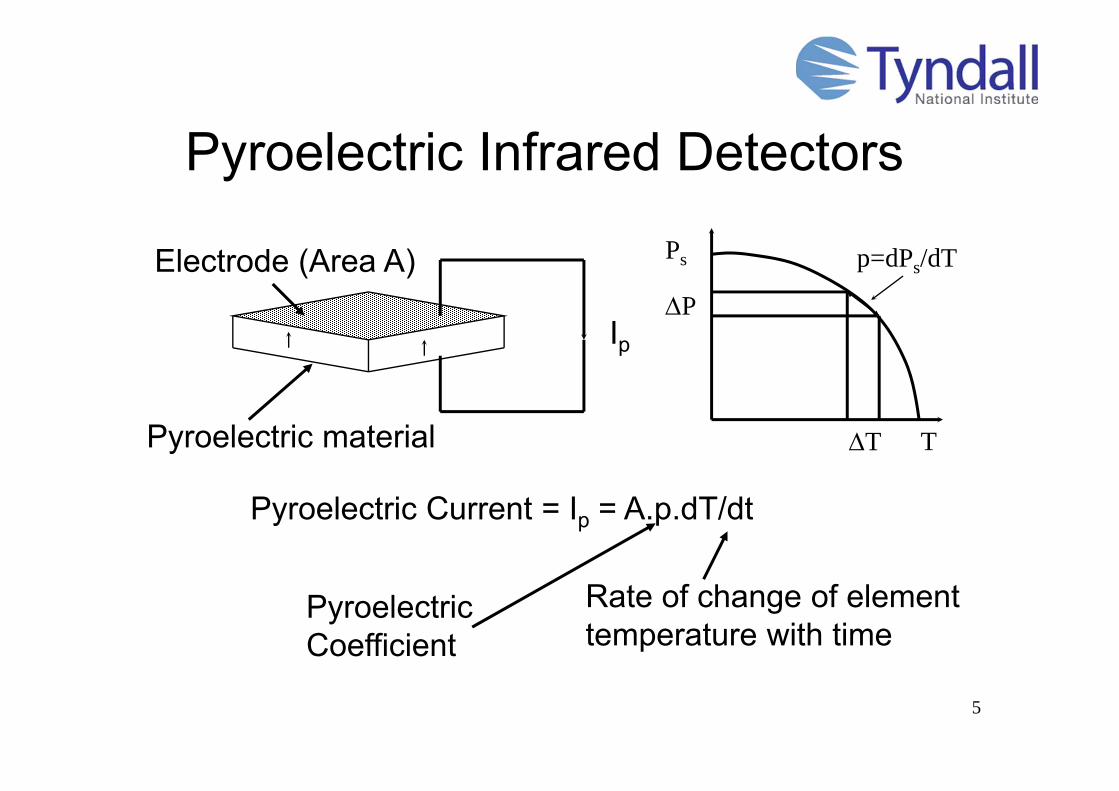
Pyroelectric Infrared Detectors
Electrode (Area A)
Pyroelectric material
Ip
Ps
P
T T
p=dPs/dT
Pyroelectric Coefficient
Rate of change of element temperature with time
Pyroelectric Current = Ip = A.p.dT/dt

6
RGipd
Incident radiation(Power W(t))
Electrode(Area A, Emissivity )
Thermal Conductance
CE
VS
RL
CA
Vo
0V
Polar axis of element
IR Temperaturechange
Pyroelectriccurrent
Voltage Output
Schematic diagram ofpyroelectric infra-red detector
Devices are “AC” coupled to radiation flux
7
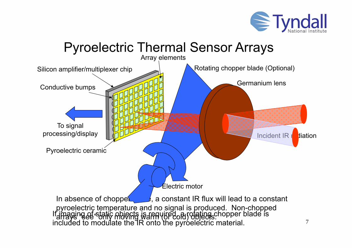
Silicon amplifier/multiplexer chip
Pyroelectric Thermal Sensor Arrays
To signal processing/display
In absence of chopper blade, a constant IR flux will lead to a constant pyroelectric temperature and no signal is produced. Non-chopped arrays “see” only moving warm (or cold) objects.
Conductive bumps
If imaging of static objects is required, a rotating chopper blade is included to modulate the IR onto the pyroelectric material.
Array elements
Pyroelectric ceramic
Rotating chopper blade (Optional)
Electric motor
Germanium lens
Incident IR radiation

8
Packaged Pyroelectric Array
www.irisys.org

9
People Sensing
What the Array ‘Sees’Field of View
10cm
www.irisys.org
10
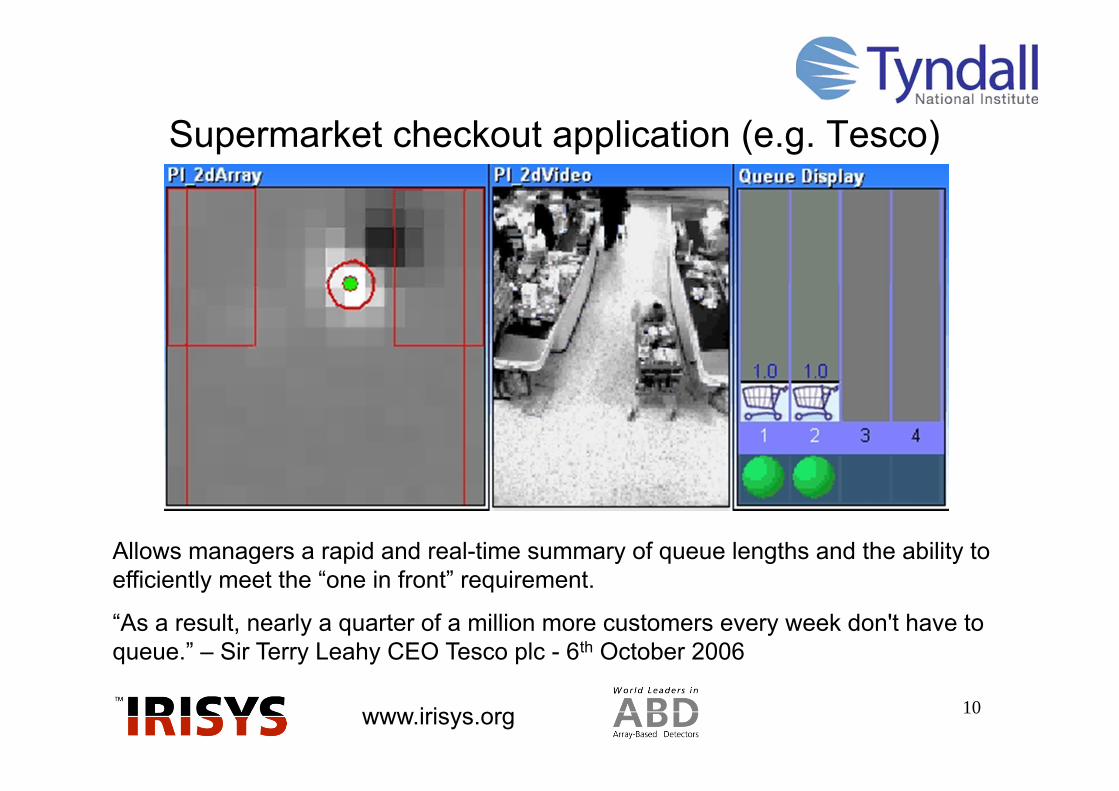
Supermarket checkout application (e.g. Tesco)
Allows managers a rapid and real-time summary of queue lengths and the ability to efficiently meet the “one in front” requirement.
“As a result, nearly a quarter of a million more customers every week don't have to queue.” – Sir Terry Leahy CEO Tesco plc - 6th October 2006
www.irisys.org

11
• Chopped operation• Gives thermal reading• Low cost• Applications to machine
monitoring and process control
Imaging Radiometer
www.irisys.org
16x16
16x16 Interpolated to 128x128

12
Pyroelectric Ceramics

13
We also require:• Good mechanical & chemical
characteristics• For focal plane preparation
• Lapping/polishing• Metallisation• Photolithography• Reticulation• Hybridization technology
• Thin film devices• Require determination of
properties in thin films
Important Properties Relevant to Pyroelectric Arrays
• Pyroelectric coefficient• Dielectric properties
• Dielectric constant• Dielectric loss
• Thermal properties• Specific heat• Density• Thermal conductivity
• Electrical Resistivity• Piezoelectric properties
• Determines microphonic noise, secondary & tertiary pyro effects
14
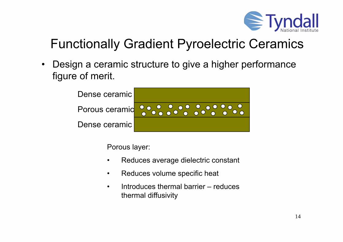
Functionally Gradient Pyroelectric Ceramics• Design a ceramic structure to give a higher performance
figure of merit.
Dense ceramic
Porous ceramic
Dense ceramic
Porous layer:
• Reduces average dielectric constant
• Reduces volume specific heat
• Introduces thermal barrier – reduces thermal diffusivity

15
Functionally Gradient Pyroelectric Ceramics -Manufacture
Roll of celluloseacetate sheetas carrier tape
Flat glass support
Slip Hopper
Ceramic Slip
Doctor Blade
Infra-red lamps
Drying zoneMotion ofcarrier tape
Tape cast with latex binder
PZT plus 50 micron starch granules
Standard Tape (55% solids)
Laminate
1:1:1 1:2:1
Sinter
A. Navarro, R.W. Whatmore and J.R. Alcock (2004) “Preparation of functionally gradient PZT ceramics using tape casting” J. Electroceramics 13 (1-3) 413-416
16
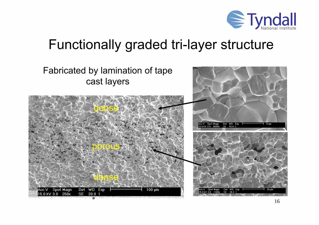
dense
porous
dense
Functionally graded tri-layer structure
Fabricated by lamination of tape cast layers

17
Theoretical Analysis
)231( LDL P
Permittivity:Bruggeman Model1:
100
120
140
160
180
200
220
240
260
280
0 5 10 15 20 25 30 35Porosity of Layer (%)
Perm
ittiv
ity
2.50
2.60
2.70
2.80
2.90
3.00
3.10
3.20
0 5 10 15Average Porosity (%)
Aver
age
Pyro
elec
tric
Coe
ffici
ent
(10-4
Cm
-2K-1
)
Pyroelectric effect:Assume pyroelectric effect is proportional to the volume of pyroelectric material between the electrodes
pA=pD(1-PA)
1. Bruggeman D.A.G. Ann. Phys. Lpz, (1935) 24, 636
D, pD = permittivity, pyro coefficient of fully-dense ceramic
18
0.04000.04200.0440
0.04600.04800.05000.05200.0540
0.05600.05800.0600
0 2 4 6 8 10 12 14Average Porosity (%)
Volta
ge F
igur
e of
Mer
it (V
m2 J-1
)
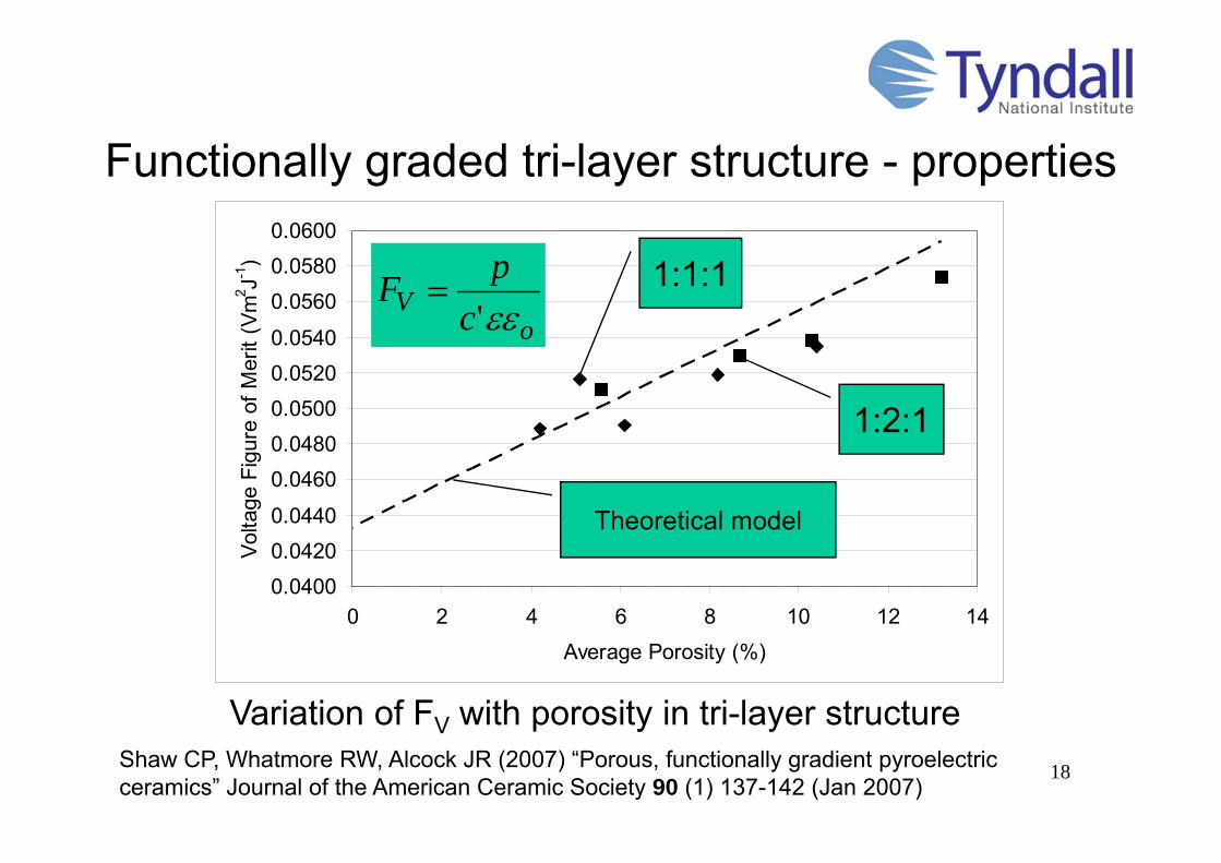
Functionally graded tri-layer structure - properties
Variation of FV with porosity in tri-layer structure
oV c
pF'
Theoretical model
1:1:1
1:2:1
Shaw CP, Whatmore RW, Alcock JR (2007) “Porous, functionally gradient pyroelectric ceramics” Journal of the American Ceramic Society 90 (1) 137-142 (Jan 2007)

19
Pyroelectric Thin Films & MEMS Structures

20
Integrated Arrays using Ferroelectric Thin Films
Top electrode
Electrical connection
Contact 'foot'
Ferroelectriclayer
Silicon substrateVacuum gap
Bridge 'leg'
Requires high quality ferroelectric thin films at low deposition temperatures (<550ºC for survival of Al/Si metallisation)
• Low cost
• Thin films (low thermal mass)
• Excellent isolation
• High performance
IR absorption in element
21
20 30 40 50
2Theta(Deg)
Inte
nsity
(a.u
)
[111][Pt]
[100][200]
PMZT
PZT
PtSi
100nm
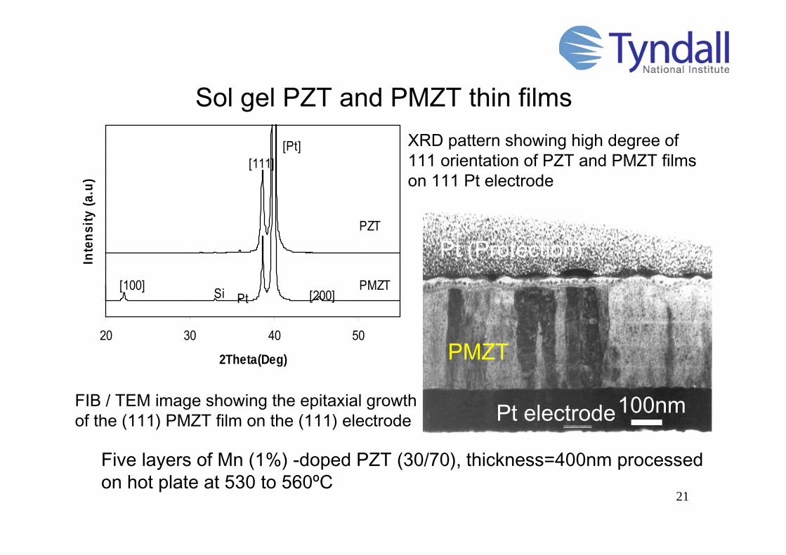
Five layers of Mn (1%) -doped PZT (30/70), thickness=400nm processed on hot plate at 530 to 560ºC
Pt (Protection)
PMZT
Pt electrode
XRD pattern showing high degree of 111 orientation of PZT and PMZT films on 111 Pt electrode
FIB / TEM image showing the epitaxial growth of the (111) PMZT film on the (111) electrode
Sol gel PZT and PMZT thin films

22
Dielectric (33Hz) and Pyroelectric Properties of PZT and PMZT (M=1%Mn)Films
Pyroelectric coefficient 2.11 3.52 x10⁻⁴ (C/m2K)
Figure of Merit FD (33Hz) 1.15 3.85 x10⁻⁵ (Pa-0.5)
PZT3070 PMZT3070
tan' oD c
pF
33-100Hz
Mn doping leads to a significant reduction in dielectric constant and loss and hence a large improvement in the pyroelectric FD. Best FD is equivalent to bulk pyroelectric ceramics
PZT3070 PMZT3070
Dielectric Constant 375 260Dielectric Loss (%) 1.61 0.06
NB: All dielectric properties measured at low frequencies
Q. Zhang and R.W. Whatmore (2003) “Improved ferroelectric and pyroelectric properties in Mn-doped lead zirconate titanate thin films” J. Appl. Phys. 94 (8) 5228-5233

23
Pyro IR Detectors with Integrated Radiation Collectors• It is not possible for the active area of the thermal detector to fill the
available space in the pixel because of the need for good thermal isolation (long legs)
• Exploit the principle of the non-imaging radiation collector in order to collect the radiation from an area close to that of the full pixel down onto the active area of the detector.
• Smaller active areas will give higher specific detectivity, if the radiation is collected from a larger area into a detector with small thermal mass
Conductive Bump
Pyroelectric element
HARM micromachined silicon wafer
Radiation collector cavities
Si Readout IC
Incident IR
Schematic of Concept

24
CPC Cavity Device Structures
Optical micrographs
SEM cross section of detector structure with isotropically-etched cavity
Optical micrographs showing the detector structures and contact areas. Note the thermal isolation structure defined for the sensitive area
Contact
Sensitive area
100m
a
b100m
Collector cavity
c
R.W. Whatmore, S. Landi, C.P. Shaw and P.B. Kirby “Pyroelectric Arrays using Ceramics and Thin Films Integrated Radiation Collectors: Design Fabrication and Testing” Ferroelectrics 31811-22 (2005)
Collection efficiency of x2 demonstrated
25
Giant Electrocaloric Effects in Ferroelectric Thin Films
26
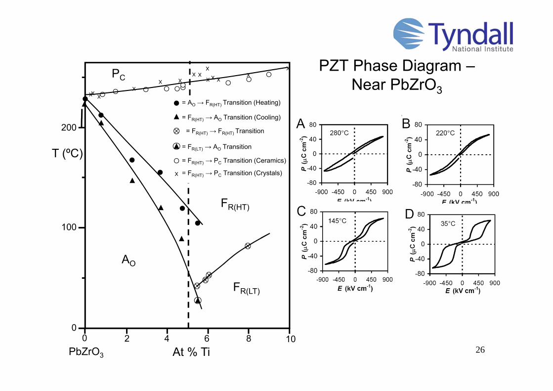
PZT Phase Diagram –Near PbZrO3
100
200
00 2 4 6 8 10
AO
FR(LT)
FR(HT)
= FR(HT) → FR(HT) Transition
T (ºC)
At % Ti
PC
= AO → FR(HT) Transition (Heating)
= FR(HT) → AO Transition (Cooling)
= FR(HT) → PC Transition (Ceramics)
= FR(LT) → AO Transition
= FR(HT) → PC Transition (Crystals)
PbZrO3

27
Electro-caloric Effects in PZT95/5 Films
dETPT
cT
E
E
E ,
2
1'
1
T(ºC)
Temperature change can be calculated from:
Previous highest T=2.5K in
Pb0.99Nb0.02(Zr0.75Sn0.20Ti0.05)O3
ceramics at 750V (30kVcm-1)

28
Why is Effect so big?• Electric fields that can be applied to a thin film
are much greater than can be obtained in the bulk (480kV/cm cf 30kV/cm)
• PZT95/05 sits at a very interesting point in the phase diagram– Tricritical behaviour in the FR(HT) to PC Transition1
– Change from AO to FR(LT) phase at room temperature
1. R.W.Whatmore, R. Clarke, A.M. Glazer: "Tricritical Behaviour of PbZrxTi1-xO3 Solid Solutions", J. Phys. C.: Solid State Physics 11 3089-3102 (1978)
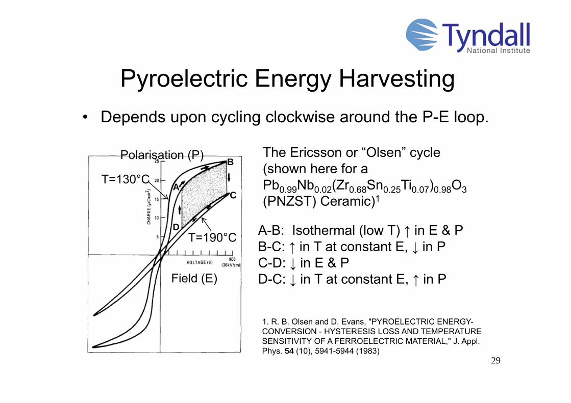
Pyroelectric Energy Harvesting• Depends upon cycling clockwise around the P-E loop.
29
The Ericsson or “Olsen” cycle (shown here for a Pb0.99Nb0.02(Zr0.68Sn0.25Ti0.07)0.98O3(PNZST) Ceramic)1
1. R. B. Olsen and D. Evans, "PYROELECTRIC ENERGY-CONVERSION - HYSTERESIS LOSS AND TEMPERATURE SENSITIVITY OF A FERROELECTRIC MATERIAL," J. Appl. Phys. 54 (10), 5941-5944 (1983)
A-B: Isothermal (low T) ↑ in E & PB-C: ↑ in T at constant E, ↓ in PC-D: ↓ in E & PD-C: ↓ in T at constant E, ↑ in P
T=130°C
T=190°C
A
B
C
D
Field (E)
Polarisation (P)

Pyroelectric Energy Harvesting
• Other cycle types
30
Dis
plac
emen
t (D
)Electric Field (E)
Stirling cycle
Dis
plac
emen
t (D
)
Electric Field (E)
CoolIsotherm
HotIsotherm
OpenCircuit
OpenCircuit
A
B C
D
Resistive cycle
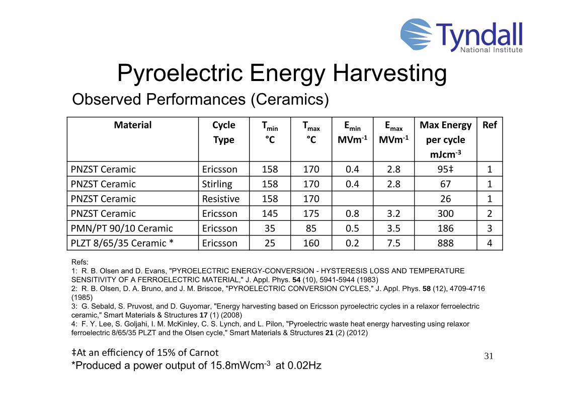
Pyroelectric Energy Harvesting
31
Observed Performances (Ceramics)Material Cycle
TypeTmin
°CTmax
°CEmin
MVm‐1
Emax
MVm‐1
Max Energy per cyclemJcm‐3
Ref
PNZST Ceramic Ericsson 158 170 0.4 2.8 95‡ 1PNZST Ceramic Stirling 158 170 0.4 2.8 67 1PNZST Ceramic Resistive 158 170 26 1PNZST Ceramic Ericsson 145 175 0.8 3.2 300 2PMN/PT 90/10 Ceramic Ericsson 35 85 0.5 3.5 186 3PLZT 8/65/35 Ceramic * Ericsson 25 160 0.2 7.5 888 4
Refs:1: R. B. Olsen and D. Evans, "PYROELECTRIC ENERGY-CONVERSION - HYSTERESIS LOSS AND TEMPERATURE SENSITIVITY OF A FERROELECTRIC MATERIAL," J. Appl. Phys. 54 (10), 5941-5944 (1983)2: R. B. Olsen, D. A. Bruno, and J. M. Briscoe, "PYROELECTRIC CONVERSION CYCLES," J. Appl. Phys. 58 (12), 4709-4716 (1985)3: G. Sebald, S. Pruvost, and D. Guyomar, "Energy harvesting based on Ericsson pyroelectric cycles in a relaxor ferroelectric ceramic," Smart Materials & Structures 17 (1) (2008)4: F. Y. Lee, S. Goljahi, I. M. McKinley, C. S. Lynch, and L. Pilon, "Pyroelectric waste heat energy harvesting using relaxor ferroelectric 8/65/35 PLZT and the Olsen cycle," Smart Materials & Structures 21 (2) (2012)
‡At an efficiency of 15% of Carnot*Produced a power output of 15.8mWcm-3 at 0.02Hz

Pyroelectric Energy Harvesting
32
Predicted Performances (Thin Films)
Material Cycle Type T°C
EMVm‐1
Max Energy per cyclemJcm‐3
η /ηCarnot
PMN/PT 90/10 Ericsson 75 90 432 34PZT95/05 Ericsson 220 78 596 54
G. Sebald, S. Pruvost, and D. Guyomar, "Energy harvesting based on Ericsson pyroelectric cycles in a relaxor ferroelectric ceramic," Smart Materials & Structures 17 (1) (2008)A. S. Mischenko, Q. Zhang, R. W. Whatmore, J. F. Scott, and N. D. Mathur, "Giant electrocaloric effect in the thin film relaxor ferroelectric 0.9 PbMg(1/3)Nb(2/3)O(3)-0.1 PbTiO(3) near room temperature," Appl. Phys. Lett. 89 (24) (2006)A. Mischenko, Q. Zhang, J.F. Scott, R.W. Whatmore and N.D. Mathur “Giant electrocaloric effect in thin film PbZr0.95Ti0.05O3” Science 311 1270-1271 (3rd March 2006)
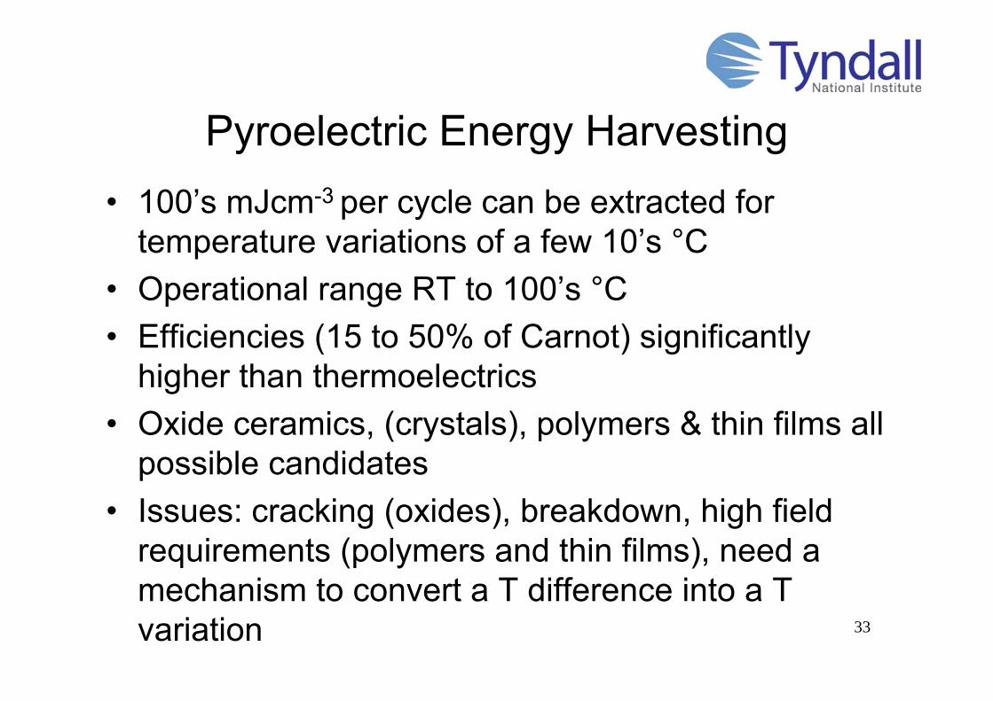
Pyroelectric Energy Harvesting• 100’s mJcm-3 per cycle can be extracted for
temperature variations of a few 10’s °C• Operational range RT to 100’s °C• Efficiencies (15 to 50% of Carnot) significantly
higher than thermoelectrics• Oxide ceramics, (crystals), polymers & thin films all
possible candidates• Issues: cracking (oxides), breakdown, high field
requirements (polymers and thin films), need a mechanism to convert a T difference into a T variation 33
34
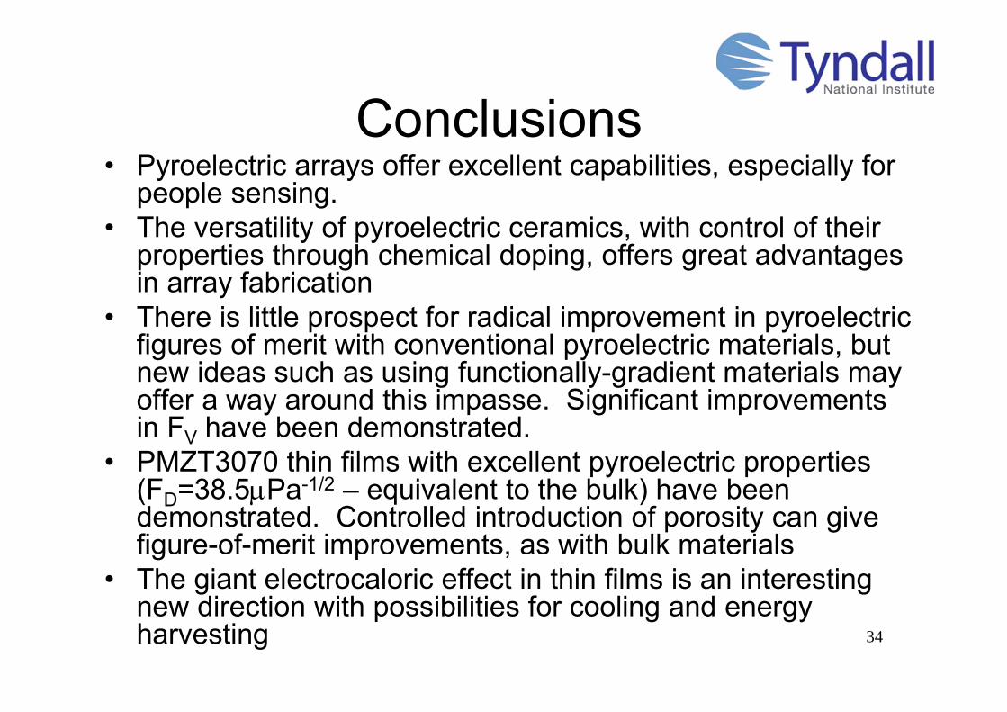
Conclusions• Pyroelectric arrays offer excellent capabilities, especially for
people sensing.• The versatility of pyroelectric ceramics, with control of their
properties through chemical doping, offers great advantages in array fabrication
• There is little prospect for radical improvement in pyroelectric figures of merit with conventional pyroelectric materials, but new ideas such as using functionally-gradient materials may offer a way around this impasse. Significant improvements in FV have been demonstrated.
• PMZT3070 thin films with excellent pyroelectric properties (FD=38.5Pa-1/2 – equivalent to the bulk) have been demonstrated. Controlled introduction of porosity can give figure-of-merit improvements, as with bulk materials
• The giant electrocaloric effect in thin films is an interesting new direction with possibilities for cooling and energy harvesting