read.pudn.comread.pudn.com/downloads67/ebook/243807/java3dguide.pdf · iii contents preface . . . ....
TRANSCRIPT

i
Java™ 3D APISpecification
Version 1.0, August 1, 1997
2550 Garcia AvenueMountain View, CA 94043 USA415 960-1300 fax 415 969-9131
A Sun Microsystems, Inc. BusinessJavaSoft

ii
1997 Sun Microsystems, Inc.2550 Garcia Avenue, Mountain View, California 94043-1100 U.S.A.All rights reserved.
RESTRICTED RIGHTS LEGEND: Use, duplication, or disclosure by the United StatesGovernment is subject to the restrictions set forth in DFARS 252.227-7013 (c)(1)(ii) and FAR52.227-19.ed
The release described in this document may be protected by one or more U.S. patents, foreignpatents, or pending applications.
Sun Microsystems, Inc. (SUN) hereby grants to you a fully paid, nonexclusive, nontransferable,perpetual, worldwide limited license (without the right to sublicense) under SUN's intellectualproperty rights that are essential to practice this specification. This license allows and is limited tothe creation and distribution of clean-room implementations of this specification that (i) arecomplete implementations of this specification, (ii) pass all test suites relating to this specificationthat are available from SUN, (iii) do not derive from SUN source code or binary materials, and (iv)do not include any SUN binary materials without an appropriate and separate license from SUN.
Java and JavaScript are trademarks of Sun Microsystems, Inc. Sun, Sun Microsystems, the Sunlogo, Java and HotJava are trademarks or registered trademarks of Sun Microsystems, Inc. UNIX®
is a registered trademark in the United States and other countries, exclusively licensed through X/Open Company, Ltd. All other product names mentioned herein are the trademarks of theirrespective owners.
THIS PUBLICATION IS PROVIDED “AS IS” WITHOUT WARRANTY OF ANY KIND,EITHER EXPRESS OR IMPLIED, INCLUDING, BUT NOT LIMITED TO, THE IMPLIEDWARRANTIES OF MERCHANTABILITY, FITNESS FOR A PARTICULAR PURPOSE, ORNON-INFRINGEMENT.
THIS PUBLICATION COULD INCLUDE TECHNICAL INACCURACIES ORTYPOGRAPHICAL ERRORS. CHANGES ARE PERIODICALLY ADDED TO THEINFORMATION HEREIN; THESE CHANGES WILL BE INCORPORATED IN NEWEDITIONS OF THE PUBLICATION. SUN MICROSYSTEMS, INC. MAY MAKEIMPROVEMENTS AND/OR CHANGES IN THE PRODUCT(S) AND/OR THE PROGRAM(S)DESCRIBED IN THIS PUBLICATION AT ANY TIME

. xv
1. . .1 . .2 .2. .2.3 . .4 .4 .4 .5. .5. .5. .6 . .6 .6. .9 .9
15. .16.16.16.17. .17.19.22. .23323 .23.24.24242525
Contents
Preface . . . . . . . . . . . . . . . . . . . . . . . . . . . . . . . . . . . . . . . . . . . . . . . . .
1 Introduction to Java 3D . . . . . . . . . . . . . . . . . . . . . . . . . . . . . . . . . .1.1 Goals . . . . . . . . . . . . . . . . . . . . . . . . . . . . . . . . . . . . . . . . . . . . . . . . . 1.2 Programming Paradigm. . . . . . . . . . . . . . . . . . . . . . . . . . . . . . . . . . . .
1.2.1 The Scene Graph Programming Model . . . . . . . . . . . . . .1.2.2 Rendering Modes . . . . . . . . . . . . . . . . . . . . . . . . . . . . . . 1.2.3 Extensibility . . . . . . . . . . . . . . . . . . . . . . . . . . . . . . . . . . .
1.3 High Performance . . . . . . . . . . . . . . . . . . . . . . . . . . . . . . . . . . . . . . . .1.3.1 Layered Implementation. . . . . . . . . . . . . . . . . . . . . . . . . .1.3.2 Target Hardware Platforms . . . . . . . . . . . . . . . . . . . . . . .
1.4 Support for Building Applications and Applets . . . . . . . . . . . . . . . . . .1.4.1 Browsers . . . . . . . . . . . . . . . . . . . . . . . . . . . . . . . . . . . . . 1.4.2 Games . . . . . . . . . . . . . . . . . . . . . . . . . . . . . . . . . . . . . . .
1.5 Overview of Java 3D Object Hierarchy. . . . . . . . . . . . . . . . . . . . . . . . 1.6 Structuring the Java 3D Program. . . . . . . . . . . . . . . . . . . . . . . . . . . . .
1.6.1 Java 3D Application Scene Graph . . . . . . . . . . . . . . . . . .1.6.2 Recipe for Java 3D Program. . . . . . . . . . . . . . . . . . . . . . 1.6.3 HelloUniverse: A Sample Java 3D Program . . . . . . . . . .
2 Scene Graph Overview. . . . . . . . . . . . . . . . . . . . . . . . . . . . . . . . . .2.1 Scene Graph Structure . . . . . . . . . . . . . . . . . . . . . . . . . . . . . . . . . . . .
2.1.1 Spatial Separation. . . . . . . . . . . . . . . . . . . . . . . . . . . . . . 2.1.2 State Inheritance . . . . . . . . . . . . . . . . . . . . . . . . . . . . . . . 2.1.3 Rendering . . . . . . . . . . . . . . . . . . . . . . . . . . . . . . . . . . . .
2.2 Scene Graph Objects . . . . . . . . . . . . . . . . . . . . . . . . . . . . . . . . . . . . . 2.2.1 Node Objects . . . . . . . . . . . . . . . . . . . . . . . . . . . . . . . . . 2.2.2 NodeComponent Objects . . . . . . . . . . . . . . . . . . . . . . . .
2.3 Scene Graph Superstructure Objects . . . . . . . . . . . . . . . . . . . . . . . . . 2.3.1 VirtualUniverse Object. . . . . . . . . . . . . . . . . . . . . . . . . . .22.3.2 Locale Object . . . . . . . . . . . . . . . . . . . . . . . . . . . . . . . . . .
2.4 Scene Graph Viewing Objects. . . . . . . . . . . . . . . . . . . . . . . . . . . . . . .2.4.1 Canvas3D Object . . . . . . . . . . . . . . . . . . . . . . . . . . . . . . 2.4.2 Screen3D Object. . . . . . . . . . . . . . . . . . . . . . . . . . . . . . . 2.4.3 View Object . . . . . . . . . . . . . . . . . . . . . . . . . . . . . . . . . . .2.4.4 PhysicalBody Object . . . . . . . . . . . . . . . . . . . . . . . . . . . .2.4.5 PhysicalEnvironment Object . . . . . . . . . . . . . . . . . . . . . .
iii

Java 3D API Specification—Version 1.0 August 1, 1997
iv
27. 27. . 28
29 . 29. 29293030. 32323233
37 . 37 . 39. 41 . 43 . 43. 43 . 45
47 . 47 . 48. 50 . 51. 53 . 545656
. 5759596061 . 636767
. 71. . 77. 79 . 80 . 80. 82
3 Scene Graph Superstructure . . . . . . . . . . . . . . . . . . . . . . . . . . . . .3.1 The Virtual Universe . . . . . . . . . . . . . . . . . . . . . . . . . . . . . . . . . . . . . 3.2 Establishing a Scene. . . . . . . . . . . . . . . . . . . . . . . . . . . . . . . . . . . . . 3.3 Loading a Virtual Universe . . . . . . . . . . . . . . . . . . . . . . . . . . . . . . . . .3.4 Coordinate Systems . . . . . . . . . . . . . . . . . . . . . . . . . . . . . . . . . . . . . .3.5 High Resolution Coordinates . . . . . . . . . . . . . . . . . . . . . . . . . . . . . . .
3.5.1 Java 3D High-resolution Coordinates . . . . . . . . . . . . . . .3.5.2 Java 3D Virtual World Coordinates . . . . . . . . . . . . . . . .3.5.3 Details of High-resolution Coordinates. . . . . . . . . . . . . .
3.6 API for Superstructure Objects . . . . . . . . . . . . . . . . . . . . . . . . . . . . . 3.6.1 VirtualUniverse Object . . . . . . . . . . . . . . . . . . . . . . . . . .3.6.2 Locale Object . . . . . . . . . . . . . . . . . . . . . . . . . . . . . . . . .3.6.3 HiResCoord Object . . . . . . . . . . . . . . . . . . . . . . . . . . . . .
4 Group Node Objects . . . . . . . . . . . . . . . . . . . . . . . . . . . . . . . . . . . .4.1 Group Node . . . . . . . . . . . . . . . . . . . . . . . . . . . . . . . . . . . . . . . . . . . .4.2 BranchGroup Node. . . . . . . . . . . . . . . . . . . . . . . . . . . . . . . . . . . . . . .4.3 TransformGroup Node . . . . . . . . . . . . . . . . . . . . . . . . . . . . . . . . . . . . 4.4 OrderedGroup Node . . . . . . . . . . . . . . . . . . . . . . . . . . . . . . . . . . . . . .4.5 DecalGroup Node. . . . . . . . . . . . . . . . . . . . . . . . . . . . . . . . . . . . . . . .4.6 Switch Node . . . . . . . . . . . . . . . . . . . . . . . . . . . . . . . . . . . . . . . . . . . . 4.7 SharedGroup Node . . . . . . . . . . . . . . . . . . . . . . . . . . . . . . . . . . . . . . .
5 Leaf Node Objects . . . . . . . . . . . . . . . . . . . . . . . . . . . . . . . . . . . . . .5.1 Leaf Node . . . . . . . . . . . . . . . . . . . . . . . . . . . . . . . . . . . . . . . . . . . . . .5.2 Shape3D Node . . . . . . . . . . . . . . . . . . . . . . . . . . . . . . . . . . . . . . . . . .5.3 BoundingLeaf Node . . . . . . . . . . . . . . . . . . . . . . . . . . . . . . . . . . . . . . 5.4 Background Node. . . . . . . . . . . . . . . . . . . . . . . . . . . . . . . . . . . . . . . .5.5 Clip Node . . . . . . . . . . . . . . . . . . . . . . . . . . . . . . . . . . . . . . . . . . . . . . 5.6 Fog Node . . . . . . . . . . . . . . . . . . . . . . . . . . . . . . . . . . . . . . . . . . . . . .
5.6.1 ExponentialFog Node . . . . . . . . . . . . . . . . . . . . . . . . . . .5.6.2 LinearFog Node. . . . . . . . . . . . . . . . . . . . . . . . . . . . . . . .
5.7 Light Node . . . . . . . . . . . . . . . . . . . . . . . . . . . . . . . . . . . . . . . . . . . . . 5.7.1 AmbientLight Node. . . . . . . . . . . . . . . . . . . . . . . . . . . . .5.7.2 DirectionalLight Node. . . . . . . . . . . . . . . . . . . . . . . . . . .5.7.3 PointLight Node . . . . . . . . . . . . . . . . . . . . . . . . . . . . . . .5.7.4 SpotLight Node . . . . . . . . . . . . . . . . . . . . . . . . . . . . . . . .
5.8 Sound Node . . . . . . . . . . . . . . . . . . . . . . . . . . . . . . . . . . . . . . . . . . . .5.8.1 BackgroundSound Node . . . . . . . . . . . . . . . . . . . . . . . . .5.8.2 PointSound Node. . . . . . . . . . . . . . . . . . . . . . . . . . . . . . .5.8.3 ConeSound Node. . . . . . . . . . . . . . . . . . . . . . . . . . . . . .
5.9 Soundscape Node . . . . . . . . . . . . . . . . . . . . . . . . . . . . . . . . . . . . . . . 5.10 ViewPlatform Node . . . . . . . . . . . . . . . . . . . . . . . . . . . . . . . . . . . . . . 5.11 Behavior Node . . . . . . . . . . . . . . . . . . . . . . . . . . . . . . . . . . . . . . . . . .5.12 Morph Node . . . . . . . . . . . . . . . . . . . . . . . . . . . . . . . . . . . . . . . . . . . .5.13 Link Node. . . . . . . . . . . . . . . . . . . . . . . . . . . . . . . . . . . . . . . . . . . . . .

. 83 . .83 .8385. .86 .87. .88.90 .91.92.92
95 .95.9699000202030506070912131316
17122232424252526
126271283032
.142424848484849
6 Reusing Scene Graphs . . . . . . . . . . . . . . . . . . . . . . . . . . . . . . . . . 6.1 Sharing Subgraphs. . . . . . . . . . . . . . . . . . . . . . . . . . . . . . . . . . . . . . .
6.1.1 SharedGroup Node . . . . . . . . . . . . . . . . . . . . . . . . . . . . .6.1.2 Link Leaf Node. . . . . . . . . . . . . . . . . . . . . . . . . . . . . . . . .
6.2 Cloning Subgraphs. . . . . . . . . . . . . . . . . . . . . . . . . . . . . . . . . . . . . . . 6.2.1 References To Node Component Objects . . . . . . . . . . .6.2.2 References to Other Scene Graph Nodes . . . . . . . . . . . 6.2.3 Dangling References. . . . . . . . . . . . . . . . . . . . . . . . . . . . 6.2.4 Subclassing Nodes . . . . . . . . . . . . . . . . . . . . . . . . . . . . .6.2.5 NodeReferenceTable Object. . . . . . . . . . . . . . . . . . . . . . 6.2.6 Example User Behavior Node . . . . . . . . . . . . . . . . . . . .
7 Node Component Objects. . . . . . . . . . . . . . . . . . . . . . . . . . . . . . . .7.1 Node Component Objects—Attributes . . . . . . . . . . . . . . . . . . . . . . . .
7.1.1 Appearance Object . . . . . . . . . . . . . . . . . . . . . . . . . . . . . 7.1.2 ColoringAttributes Object . . . . . . . . . . . . . . . . . . . . . . . .7.1.3 LineAttributes Object . . . . . . . . . . . . . . . . . . . . . . . . . . .17.1.4 PointAttributes Object . . . . . . . . . . . . . . . . . . . . . . . . . .17.1.5 PolygonAttributes Object . . . . . . . . . . . . . . . . . . . . . . . .17.1.6 RenderingAttributes Object . . . . . . . . . . . . . . . . . . . . . .17.1.7 TextureAttributes Object . . . . . . . . . . . . . . . . . . . . . . . .17.1.8 TransparencyAttributes Object. . . . . . . . . . . . . . . . . . . .17.1.9 Material Object . . . . . . . . . . . . . . . . . . . . . . . . . . . . . . . .17.1.10 Texture Object . . . . . . . . . . . . . . . . . . . . . . . . . . . . . . . .17.1.11 Texture2D Object . . . . . . . . . . . . . . . . . . . . . . . . . . . . . .17.1.12 Texture3D Object . . . . . . . . . . . . . . . . . . . . . . . . . . . . . .17.1.13 TexCoordGeneration Object. . . . . . . . . . . . . . . . . . . . . .17.1.14 MediaContainer Object. . . . . . . . . . . . . . . . . . . . . . . . . .17.1.15 AuralAttributes Object . . . . . . . . . . . . . . . . . . . . . . . . . .17.1.16 ImageComponent Object . . . . . . . . . . . . . . . . . . . . . . . .7.1.17 ImageComponent2D Object . . . . . . . . . . . . . . . . . . . . . .17.1.18 ImageComponent3D Object . . . . . . . . . . . . . . . . . . . . . .17.1.19 DepthComponent Object . . . . . . . . . . . . . . . . . . . . . . . .17.1.20 DepthComponentFloat Object . . . . . . . . . . . . . . . . . . . .17.1.21 DepthComponentInt Object . . . . . . . . . . . . . . . . . . . . . .17.1.22 DepthComponentNative Object . . . . . . . . . . . . . . . . . . .17.1.23 Bounds Object . . . . . . . . . . . . . . . . . . . . . . . . . . . . . . . .7.1.24 BoundingBox Object . . . . . . . . . . . . . . . . . . . . . . . . . . .17.1.25 BoundingSphere Object . . . . . . . . . . . . . . . . . . . . . . . . .7.1.26 BoundingPolytope Object. . . . . . . . . . . . . . . . . . . . . . . .17.1.27 Transform3D Object. . . . . . . . . . . . . . . . . . . . . . . . . . . .1
7.2 Node Component Objects—Geometry . . . . . . . . . . . . . . . . . . . . . . . 7.2.1 GeometryArray Object . . . . . . . . . . . . . . . . . . . . . . . . . .17.2.2 PointArray Object. . . . . . . . . . . . . . . . . . . . . . . . . . . . . .17.2.3 LineArray Object . . . . . . . . . . . . . . . . . . . . . . . . . . . . . .17.2.4 TriangleArray Object . . . . . . . . . . . . . . . . . . . . . . . . . . .17.2.5 QuadArray Object. . . . . . . . . . . . . . . . . . . . . . . . . . . . . .17.2.6 GeometryStripArray Object . . . . . . . . . . . . . . . . . . . . . .1
v

Java 3D API Specification—Version 1.0 August 1, 1997
vi
4950505153535354545555561561571586061621646566
671686816969691701273
7351756
77781788081
18283838318418485
7.2.7 LineStripArray Object. . . . . . . . . . . . . . . . . . . . . . . . . . 17.2.8 TriangleStripArray Object. . . . . . . . . . . . . . . . . . . . . . . 17.2.9 TriangleFanArray Object . . . . . . . . . . . . . . . . . . . . . . . 17.2.10 IndexedGeometryArray Object . . . . . . . . . . . . . . . . . . . 17.2.11 IndexedPointArray Object. . . . . . . . . . . . . . . . . . . . . . . 17.2.12 IndexedLineArray Object . . . . . . . . . . . . . . . . . . . . . . . 17.2.13 IndexedTriangleArray Object . . . . . . . . . . . . . . . . . . . . 17.2.14 IndexedQuadArray Object . . . . . . . . . . . . . . . . . . . . . . 17.2.15 IndexedGeometryStripArray Object . . . . . . . . . . . . . . . 17.2.16 IndexedLineStripArray Object . . . . . . . . . . . . . . . . . . . 17.2.17 IndexedTriangleStripArray Object . . . . . . . . . . . . . . . . 17.2.18 IndexedTriangleFanArray Object . . . . . . . . . . . . . . . . . 17.2.19 CompressedGeometry Object . . . . . . . . . . . . . . . . . . . .7.2.20 CompressedGeometryHeader Object . . . . . . . . . . . . . .7.2.21 Raster Object . . . . . . . . . . . . . . . . . . . . . . . . . . . . . . . . .7.2.22 Font3D Object . . . . . . . . . . . . . . . . . . . . . . . . . . . . . . . . 17.2.23 FontExtrusion Object . . . . . . . . . . . . . . . . . . . . . . . . . . 17.2.24 Text3D Geometry Object . . . . . . . . . . . . . . . . . . . . . . . 1
7.3 Math Component Objects. . . . . . . . . . . . . . . . . . . . . . . . . . . . . . . . . .7.3.1 Tuple Objects . . . . . . . . . . . . . . . . . . . . . . . . . . . . . . . . 17.3.2 Matrix Objects. . . . . . . . . . . . . . . . . . . . . . . . . . . . . . . . 1
8 The Java 3D View Model . . . . . . . . . . . . . . . . . . . . . . . . . . . . . . . 18.1 Why a New Model? . . . . . . . . . . . . . . . . . . . . . . . . . . . . . . . . . . . . . .
8.1.1 The Physical Environment Influences the View . . . . . . 18.2 Separation of Physical and Virtual . . . . . . . . . . . . . . . . . . . . . . . . . . .
8.2.1 The Virtual World . . . . . . . . . . . . . . . . . . . . . . . . . . . . . 18.2.2 The Physical World . . . . . . . . . . . . . . . . . . . . . . . . . . . . 1
8.3 The Objects That Define the View. . . . . . . . . . . . . . . . . . . . . . . . . . .8.4 ViewPlatform—A Place In the Virtual World . . . . . . . . . . . . . . . . . . 17
8.4.1 Moving Through the Virtual World . . . . . . . . . . . . . . . 178.4.2 Dropping In On a Favorite Place. . . . . . . . . . . . . . . . . . 18.4.3 View Attach Policy . . . . . . . . . . . . . . . . . . . . . . . . . . . . 18.4.4 Associating Geometry With a ViewPlatform . . . . . . . . 17
8.5 Generating a View . . . . . . . . . . . . . . . . . . . . . . . . . . . . . . . . . . . . . . .8.5.1 Composing Model and Viewing Transformations . . . . 178.5.2 Multiple Locales . . . . . . . . . . . . . . . . . . . . . . . . . . . . . . 1
8.6 A Minimal Environment. . . . . . . . . . . . . . . . . . . . . . . . . . . . . . . . . . . 18.7 The View Object. . . . . . . . . . . . . . . . . . . . . . . . . . . . . . . . . . . . . . . . .
8.7.1 Projection Policy . . . . . . . . . . . . . . . . . . . . . . . . . . . . . . 18.7.2 Clip Policies . . . . . . . . . . . . . . . . . . . . . . . . . . . . . . . . . 18.7.3 Projection and Clip Parameters . . . . . . . . . . . . . . . . . . .8.7.4 Frame Start Time and Duration. . . . . . . . . . . . . . . . . . . 18.7.5 Scene Antialiasing. . . . . . . . . . . . . . . . . . . . . . . . . . . . . 18.7.6 Depth Buffer . . . . . . . . . . . . . . . . . . . . . . . . . . . . . . . . . 1
8.8 The Screen3D Object . . . . . . . . . . . . . . . . . . . . . . . . . . . . . . . . . . . . .8.9 The Canvas3D Object. . . . . . . . . . . . . . . . . . . . . . . . . . . . . . . . . . . . .
8.9.1 Window System Provided Parameters . . . . . . . . . . . . . 1

185.186186
189189901
.191191192192194
7.197198999900.200.200201202020303
.212121621721920212222
232425
22622728
2292930231.232233
8.9.2 Other Canvas3D Parameters. . . . . . . . . . . . . . . . . . . . . .8.10 The PhysicalBody Object . . . . . . . . . . . . . . . . . . . . . . . . . . . . . . . . . 8.11 The PhysicalEnvironment Object . . . . . . . . . . . . . . . . . . . . . . . . . . . .
9 Input Devices . . . . . . . . . . . . . . . . . . . . . . . . . . . . . . . . . . . . . . . . .9.1 InputDevice Interface . . . . . . . . . . . . . . . . . . . . . . . . . . . . . . . . . . . . .
9.1.1 The Abstract Interface . . . . . . . . . . . . . . . . . . . . . . . . . .19.1.2 Instantiating And Registering A New Device . . . . . . . .19
9.2 Sensors. . . . . . . . . . . . . . . . . . . . . . . . . . . . . . . . . . . . . . . . . . . . . . . .9.2.1 Using and Assigning Sensors . . . . . . . . . . . . . . . . . . . . .9.2.2 Behind the (Sensor) Scenes . . . . . . . . . . . . . . . . . . . . . .9.2.3 The Sensor Object . . . . . . . . . . . . . . . . . . . . . . . . . . . . .9.2.4 The SensorRead Object . . . . . . . . . . . . . . . . . . . . . . . . .
10 Behaviors, Interpolators, and Picking . . . . . . . . . . . . . . . . . . . . 1910.1 Behavior Object . . . . . . . . . . . . . . . . . . . . . . . . . . . . . . . . . . . . . . . . .
10.1.1 Code Structure . . . . . . . . . . . . . . . . . . . . . . . . . . . . . . . .10.1.2 WakeupCondition Object . . . . . . . . . . . . . . . . . . . . . . . .110.1.3 WakeupCriterion Object. . . . . . . . . . . . . . . . . . . . . . . . .110.1.4 Composing WakeupCriterion Objects . . . . . . . . . . . . . .2
10.2 Composing Behaviors . . . . . . . . . . . . . . . . . . . . . . . . . . . . . . . . . . . . 10.3 Scheduling . . . . . . . . . . . . . . . . . . . . . . . . . . . . . . . . . . . . . . . . . . . . . 10.4 How Java 3D Performs Execution Culling . . . . . . . . . . . . . . . . . . . . .10.5 The Behavior API . . . . . . . . . . . . . . . . . . . . . . . . . . . . . . . . . . . . . . . .
10.5.1 The Behavior Node. . . . . . . . . . . . . . . . . . . . . . . . . . . . .210.5.2 WakeupCondition Object . . . . . . . . . . . . . . . . . . . . . . . .210.5.3 The WakeupCriterion Objects . . . . . . . . . . . . . . . . . . . .2
10.6 Interpolator Behaviors . . . . . . . . . . . . . . . . . . . . . . . . . . . . . . . . . . . . 10.6.1 Mapping Time to Alpha . . . . . . . . . . . . . . . . . . . . . . . . .210.6.2 Acceleration of Alpha. . . . . . . . . . . . . . . . . . . . . . . . . . .210.6.3 The Alpha Class . . . . . . . . . . . . . . . . . . . . . . . . . . . . . . .10.6.4 The Interpolator Base Class . . . . . . . . . . . . . . . . . . . . . .10.6.5 PositionInterpolator Object. . . . . . . . . . . . . . . . . . . . . . .210.6.6 RotationInterpolator Object . . . . . . . . . . . . . . . . . . . . . .210.6.7 ColorInterpolator Object. . . . . . . . . . . . . . . . . . . . . . . . .210.6.8 ScaleInterpolator Object . . . . . . . . . . . . . . . . . . . . . . . . .210.6.9 SwitchValueInterpolator Object . . . . . . . . . . . . . . . . . . .210.6.10 TransparencyInterpolator Object . . . . . . . . . . . . . . . . . .210.6.11 PositionPathInterpolator Object . . . . . . . . . . . . . . . . . . .210.6.12 RotPosPathInterpolator Object . . . . . . . . . . . . . . . . . . . .10.6.13 RotPosScalePathInterpolator Object . . . . . . . . . . . . . . .10.6.14 RotationPathInterpolator Object. . . . . . . . . . . . . . . . . . .2
10.7 Level-of-Detail Behaviors . . . . . . . . . . . . . . . . . . . . . . . . . . . . . . . . . .10.7.1 LOD Object . . . . . . . . . . . . . . . . . . . . . . . . . . . . . . . . . .210.7.2 DistanceLOD Object . . . . . . . . . . . . . . . . . . . . . . . . . . .2
10.8 Billboard Behavior. . . . . . . . . . . . . . . . . . . . . . . . . . . . . . . . . . . . . . . .10.9 Picking . . . . . . . . . . . . . . . . . . . . . . . . . . . . . . . . . . . . . . . . . . . . . . . .
10.9.1 SceneGraphPath Object . . . . . . . . . . . . . . . . . . . . . . . . .
vii

Java 3D API Specification—Version 1.0 August 1, 1997
viii
35352363636
237
239239404141242
324343
24444245
4545
472474749250
25151
5725858636569747682899192
295960107
10.9.2 BranchGroup Node Pick Methods . . . . . . . . . . . . . . . . 210.9.3 Locale Node Pick Methods . . . . . . . . . . . . . . . . . . . . . . 210.9.4 PickShape Objects. . . . . . . . . . . . . . . . . . . . . . . . . . . . .10.9.5 PickPoint Object . . . . . . . . . . . . . . . . . . . . . . . . . . . . . . 210.9.6 PickRay Object . . . . . . . . . . . . . . . . . . . . . . . . . . . . . . . 210.9.7 PickSegment Object . . . . . . . . . . . . . . . . . . . . . . . . . . .
11 Audio Devices. . . . . . . . . . . . . . . . . . . . . . . . . . . . . . . . . . . . . . . . .11.1 AudioDevice Interface . . . . . . . . . . . . . . . . . . . . . . . . . . . . . . . . . . . .
11.1.1 Initialization. . . . . . . . . . . . . . . . . . . . . . . . . . . . . . . . . . 211.1.2 Audio Playback . . . . . . . . . . . . . . . . . . . . . . . . . . . . . . . 211.1.3 Device Driver Specific Data . . . . . . . . . . . . . . . . . . . . . 2
11.2 Instantiating and Registering a New Device . . . . . . . . . . . . . . . . . . .
12 The Java 3D Execution and Rendering Model . . . . . . . . . . . . . . 2412.1 Three Major Rendering Models . . . . . . . . . . . . . . . . . . . . . . . . . . . . .
12.1.1 Immediate Mode . . . . . . . . . . . . . . . . . . . . . . . . . . . . . . 212.1.2 Retained Mode . . . . . . . . . . . . . . . . . . . . . . . . . . . . . . .12.1.3 Compiled-retained Mode. . . . . . . . . . . . . . . . . . . . . . . . 2
12.2 Instantiating the Render Loop . . . . . . . . . . . . . . . . . . . . . . . . . . . . . .12.2.1 An Application-level Perspective . . . . . . . . . . . . . . . . . 212.2.2 Retained and Compiled-retained Rendering Modes . . . 2
13 Immediate Mode Rendering. . . . . . . . . . . . . . . . . . . . . . . . . . . . . 213.1 Two Styles of Immediate Mode . . . . . . . . . . . . . . . . . . . . . . . . . . . . .
13.1.1 Pure Immediate Mode Rendering . . . . . . . . . . . . . . . . . 213.1.2 Mixed Mode Rendering. . . . . . . . . . . . . . . . . . . . . . . . . 2
13.2 Canvas3D Methods . . . . . . . . . . . . . . . . . . . . . . . . . . . . . . . . . . . . . .13.3 API for Immediate Mode . . . . . . . . . . . . . . . . . . . . . . . . . . . . . . . . . .
13.3.1 GraphicsContext3D. . . . . . . . . . . . . . . . . . . . . . . . . . . . 2
A Math Objects . . . . . . . . . . . . . . . . . . . . . . . . . . . . . . . . . . . . . . . . . 2A.1 Tuple Objects . . . . . . . . . . . . . . . . . . . . . . . . . . . . . . . . . . . . . . . . . . .
A.1.1 Tuple2f Class. . . . . . . . . . . . . . . . . . . . . . . . . . . . . . . . . 2A.1.2 Tuple3b Class . . . . . . . . . . . . . . . . . . . . . . . . . . . . . . . . 2A.1.3 Tuple3d Class . . . . . . . . . . . . . . . . . . . . . . . . . . . . . . . . 2A.1.4 Tuple3f Class. . . . . . . . . . . . . . . . . . . . . . . . . . . . . . . . . 2A.1.5 Tuple4b Class . . . . . . . . . . . . . . . . . . . . . . . . . . . . . . . . 2A.1.6 Tuple4d Class . . . . . . . . . . . . . . . . . . . . . . . . . . . . . . . . 2A.1.7 Tuple4f Class. . . . . . . . . . . . . . . . . . . . . . . . . . . . . . . . . 2A.1.8 AxisAngle4d Class . . . . . . . . . . . . . . . . . . . . . . . . . . . . 2A.1.9 AxisAngle4f Class. . . . . . . . . . . . . . . . . . . . . . . . . . . . . 2A.1.10 GVector Class . . . . . . . . . . . . . . . . . . . . . . . . . . . . . . . . 2
A.2 Matrix Objects . . . . . . . . . . . . . . . . . . . . . . . . . . . . . . . . . . . . . . . . . .A.2.1 Matrix3f Class . . . . . . . . . . . . . . . . . . . . . . . . . . . . . . . . 2A.2.2 Matrix3d Class . . . . . . . . . . . . . . . . . . . . . . . . . . . . . . . 3A.2.3 Matrix4f Class . . . . . . . . . . . . . . . . . . . . . . . . . . . . . . . . 3

1421
27.327.328.328328
.330.333.333.334353638.3393403423423423423443444546
34848
349.349495151515152.352525354.355355555556
357575757
A.2.4 Matrix4d Class . . . . . . . . . . . . . . . . . . . . . . . . . . . . . . . .3A.2.5 GMatrix Class. . . . . . . . . . . . . . . . . . . . . . . . . . . . . . . . .3
B 3D Geometry Compression . . . . . . . . . . . . . . . . . . . . . . . . . . . . . 3B.1 Compression . . . . . . . . . . . . . . . . . . . . . . . . . . . . . . . . . . . . . . . . . . . B.2 Decompression . . . . . . . . . . . . . . . . . . . . . . . . . . . . . . . . . . . . . . . . . B.3 Chapter Organization. . . . . . . . . . . . . . . . . . . . . . . . . . . . . . . . . . . . . B.4 Generalized Triangle Strip. . . . . . . . . . . . . . . . . . . . . . . . . . . . . . . . . .B.5 Generalized Triangle Mesh . . . . . . . . . . . . . . . . . . . . . . . . . . . . . . . . B.6 Position Representation and Quantization. . . . . . . . . . . . . . . . . . . . . B.7 Color Representation and Quantization. . . . . . . . . . . . . . . . . . . . . . . B.8 Normal Representation and Quantization . . . . . . . . . . . . . . . . . . . . .
B.8.1 Normal as Indices . . . . . . . . . . . . . . . . . . . . . . . . . . . . . .3B.8.2 Normal Encoding Parameterization . . . . . . . . . . . . . . . .3
B.9 Modified Huffman Encoding. . . . . . . . . . . . . . . . . . . . . . . . . . . . . . . .3B.10 Geometry Compression Commands . . . . . . . . . . . . . . . . . . . . . . . . . B.11 Bit Layout of Geometry Decompression Commands . . . . . . . . . . . . .B.12 Geometry Decompression Command Bit Details . . . . . . . . . . . . . . . .
B.12.1 NOP . . . . . . . . . . . . . . . . . . . . . . . . . . . . . . . . . . . . . . . .B.12.2 setState . . . . . . . . . . . . . . . . . . . . . . . . . . . . . . . . . . . . . .B.12.3 setTable. . . . . . . . . . . . . . . . . . . . . . . . . . . . . . . . . . . . . .B.12.4 meshBufferReference . . . . . . . . . . . . . . . . . . . . . . . . . . .B.12.5 Position Sub-command. . . . . . . . . . . . . . . . . . . . . . . . . .B.12.6 Color Sub-command. . . . . . . . . . . . . . . . . . . . . . . . . . . .3B.12.7 Normal Sub-command . . . . . . . . . . . . . . . . . . . . . . . . . .3B.12.8 vertex . . . . . . . . . . . . . . . . . . . . . . . . . . . . . . . . . . . . . . .B.12.9 normal. . . . . . . . . . . . . . . . . . . . . . . . . . . . . . . . . . . . . . .3B.12.10 color . . . . . . . . . . . . . . . . . . . . . . . . . . . . . . . . . . . . . . . .
B.13 Semantics of Geometry Decompression Commands . . . . . . . . . . . . B.13.1 Header, Body to Variable Length Command . . . . . . . . .3B.13.2 Variable Length Command to Command. . . . . . . . . . . .3B.13.3 Delta Position to Position . . . . . . . . . . . . . . . . . . . . . . . .3B.13.4 Delta Color to Color . . . . . . . . . . . . . . . . . . . . . . . . . . . .3B.13.5 Encoded Delta Normal to Encoded Normal . . . . . . . . . .3B.13.6 Encoded Normal to Rectilinear Normal . . . . . . . . . . . . .3
B.14 Semantics of Vertices . . . . . . . . . . . . . . . . . . . . . . . . . . . . . . . . . . . . B.14.1 Command to Vertex . . . . . . . . . . . . . . . . . . . . . . . . . . . .3B.14.2 Vertex to Intermediate Triangle . . . . . . . . . . . . . . . . . . .3B.14.3 Intermediate Triangle to Final Triangle . . . . . . . . . . . . .3
B.15 Outline of Geometry Process. . . . . . . . . . . . . . . . . . . . . . . . . . . . . . . B.15.1 Compressing Geometry Data . . . . . . . . . . . . . . . . . . . . .B.15.2 Convert to Generalized Mesh Format . . . . . . . . . . . . . .3B.15.3 Position . . . . . . . . . . . . . . . . . . . . . . . . . . . . . . . . . . . . . .3B.15.4 Normals . . . . . . . . . . . . . . . . . . . . . . . . . . . . . . . . . . . . .3B.15.5 Colors . . . . . . . . . . . . . . . . . . . . . . . . . . . . . . . . . . . . . . .B.15.6 Collect Delta Code Statistics . . . . . . . . . . . . . . . . . . . . .3B.15.7 Position Delta Code Statistics. . . . . . . . . . . . . . . . . . . . .3B.15.8 Color Delta Code Statistics. . . . . . . . . . . . . . . . . . . . . . .3
ix

Java 3D API Specification—Version 1.0 August 1, 1997
x
5758359
1613626262
62363
3633653663666736768699370
37237337374
7475375376379
79793808081
38738738838838838938939090
B.15.9 Normal Delta Code Statistics . . . . . . . . . . . . . . . . . . . . 3B.15.10 Assign Huffman Tags . . . . . . . . . . . . . . . . . . . . . . . . . . 3B.15.11 Assemble the Pieces Into a Bitstream . . . . . . . . . . . . . .
C View Model Implementation Details . . . . . . . . . . . . . . . . . . . . . . 36C.1 An Overview of the Java 3D View Model . . . . . . . . . . . . . . . . . . . . . 3C.2 Physical Environments and Their Effects . . . . . . . . . . . . . . . . . . . . .
C.2.1 A Head-mounted Example . . . . . . . . . . . . . . . . . . . . . . 3C.2.2 A Room-mounted Example. . . . . . . . . . . . . . . . . . . . . . 3C.2.3 Impact of Head Position and Orientation On the
Camera. . . . . . . . . . . . . . . . . . . . . . . . . . . . . . . . . . . . . . 3C.3 The Coordinate Systems. . . . . . . . . . . . . . . . . . . . . . . . . . . . . . . . . . .
C.3.1 Room-mounted Coordinate Systems. . . . . . . . . . . . . . .C.3.2 Head-Mounted Coordinate Systems . . . . . . . . . . . . . . .
C.4 The ViewPlatform Object. . . . . . . . . . . . . . . . . . . . . . . . . . . . . . . . . .C.5 The View Object. . . . . . . . . . . . . . . . . . . . . . . . . . . . . . . . . . . . . . . . .
C.5.1 View Policy . . . . . . . . . . . . . . . . . . . . . . . . . . . . . . . . . . 3C.5.2 Screen Scale Policy . . . . . . . . . . . . . . . . . . . . . . . . . . . .C.5.3 Window Eyepoint Policy. . . . . . . . . . . . . . . . . . . . . . . . 3C.5.4 Monoscopic View Policy . . . . . . . . . . . . . . . . . . . . . . . 3C.5.5 Sensors and Their Location In the Virtual World . . . . . 36
C.6 The Screen3D Object . . . . . . . . . . . . . . . . . . . . . . . . . . . . . . . . . . . . .C.6.1 Screen3D Calibration Parameters . . . . . . . . . . . . . . . . .C.6.2 Accessing and Changing Head Tracker Coordinates . .
C.7 The Canvas3D Object. . . . . . . . . . . . . . . . . . . . . . . . . . . . . . . . . . . . .C.7.1 Scene Antialiasing. . . . . . . . . . . . . . . . . . . . . . . . . . . . . 3C.7.2 Accessing and Modifying An Eye’s Image-plate
Position . . . . . . . . . . . . . . . . . . . . . . . . . . . . . . . . . . . . . 3C.7.3 Canvas Width and Height . . . . . . . . . . . . . . . . . . . . . . . 3
C.8 The PhysicalBody Object . . . . . . . . . . . . . . . . . . . . . . . . . . . . . . . . . .C.9 The PhysicalEnvironment Object. . . . . . . . . . . . . . . . . . . . . . . . . . . .C.10 Viewing in Head Tracked Environments . . . . . . . . . . . . . . . . . . . . . .
C.10.1 A Room-mounted Display (Computer Monitor) WithHead-Tracking. . . . . . . . . . . . . . . . . . . . . . . . . . . . . . . . 3
C.10.2 A Head-Mounted Display, Head-Tracking . . . . . . . . . . 3C.11 Compatibility Mode . . . . . . . . . . . . . . . . . . . . . . . . . . . . . . . . . . . . . .
C.11.1 Overview of the Camera-based View Model . . . . . . . . 3C.11.2 Using the Camera-based View Model. . . . . . . . . . . . . . 3
D Exceptions . . . . . . . . . . . . . . . . . . . . . . . . . . . . . . . . . . . . . . . . . . .D.1 BadTransformException. . . . . . . . . . . . . . . . . . . . . . . . . . . . . . . . . . .D.2 CapabilityNotSetException . . . . . . . . . . . . . . . . . . . . . . . . . . . . . . . .D.3 DanglingReferenceException. . . . . . . . . . . . . . . . . . . . . . . . . . . . . . .D.4 IllegalSharingException . . . . . . . . . . . . . . . . . . . . . . . . . . . . . . . . . . .D.5 MultipleParentException . . . . . . . . . . . . . . . . . . . . . . . . . . . . . . . . . .D.6 RestrictedAccessException . . . . . . . . . . . . . . . . . . . . . . . . . . . . . . . .D.7 SceneGraphCycleException . . . . . . . . . . . . . . . . . . . . . . . . . . . . . . . .D.8 SingularMatrixException . . . . . . . . . . . . . . . . . . . . . . . . . . . . . . . . . . 3

.390
393.393393.395395404405
074078
84080909100
411
415
D.9 SoundException. . . . . . . . . . . . . . . . . . . . . . . . . . . . . . . . . . . . . . . . .
E Equations . . . . . . . . . . . . . . . . . . . . . . . . . . . . . . . . . . . . . . . . . . . .E.1 Fog Equations . . . . . . . . . . . . . . . . . . . . . . . . . . . . . . . . . . . . . . . . . . E.2 Lighting Equations. . . . . . . . . . . . . . . . . . . . . . . . . . . . . . . . . . . . . . . .E.3 Sound Equations . . . . . . . . . . . . . . . . . . . . . . . . . . . . . . . . . . . . . . . .
E.3.1 Headphone Playback Equations . . . . . . . . . . . . . . . . . . .E.3.2 Speaker Playback Equations. . . . . . . . . . . . . . . . . . . . . .
E.4 Texture Mapping Equations . . . . . . . . . . . . . . . . . . . . . . . . . . . . . . . .
F VRML Support . . . . . . . . . . . . . . . . . . . . . . . . . . . . . . . . . . . . . . . 4F.1 VRML 1.0 . . . . . . . . . . . . . . . . . . . . . . . . . . . . . . . . . . . . . . . . . . . . . .
F.1.1 Mapping VRML 1.0 Files Onto Java 3D Objects . . . . .40F.1.2 A VRML 1.0 Browsing Environment . . . . . . . . . . . . . .40
F.2 VRML 2.0 . . . . . . . . . . . . . . . . . . . . . . . . . . . . . . . . . . . . . . . . . . . . . .F.2.1 A Fundamental Mismatch . . . . . . . . . . . . . . . . . . . . . . .4F.2.2 An Approach. . . . . . . . . . . . . . . . . . . . . . . . . . . . . . . . . .4F.2.3 A Browser. . . . . . . . . . . . . . . . . . . . . . . . . . . . . . . . . . . .4F.2.4 Optimizing For Viewing Versus Editing . . . . . . . . . . . .41
Glossary . . . . . . . . . . . . . . . . . . . . . . . . . . . . . . . . . . . . . . . . . . . . . . . .
Index. . . . . . . . . . . . . . . . . . . . . . . . . . . . . . . . . . . . . . . . . . . . . . . . . . .
xi

Java 3D API Specification—Version 1.0 August 1, 1997
xii

. . .6
. . .7.16. .25 .28. .37. .41. .48. .69 . .71 .75.75 .78 . .84 . .87. . .88 . .89. .90 .96. .117.142.164170172173177213able
ble
Figures
Figure 1-1 Java 3D Object Hierarchy . . . . . . . . . . . . . . . . . . . . . . . . . . . . . . . . . . . Figure 1-2 Application Scene Graph . . . . . . . . . . . . . . . . . . . . . . . . . . . . . . . . . . . . Figure 2-1 A Java 3D Scene Graph is a DAG (Directed Acyclic Graph) . . . . . . . . . Figure 2-2 Viewing a Scene Graph . . . . . . . . . . . . . . . . . . . . . . . . . . . . . . . . . . . . . Figure 3-1 The Virtual Universe . . . . . . . . . . . . . . . . . . . . . . . . . . . . . . . . . . . . . . . .Figure 4-1 Group Node Hierarchy . . . . . . . . . . . . . . . . . . . . . . . . . . . . . . . . . . . . . . Figure 4-2 Altering the Scene Graph at Runtime. . . . . . . . . . . . . . . . . . . . . . . . . . . Figure 5-1 Leaf Node Hierarchy . . . . . . . . . . . . . . . . . . . . . . . . . . . . . . . . . . . . . . . Figure 5-2 PointSound Distance Gain Attenuation . . . . . . . . . . . . . . . . . . . . . . . . . Figure 5-3 ConeSound . . . . . . . . . . . . . . . . . . . . . . . . . . . . . . . . . . . . . . . . . . . . . . .Figure 5-4 ConeSound with a Single Distance Gain Attenuation Array . . . . . . . . . .Figure 5-5 ConeSound with Two Distance Gain Attenuation Arrays . . . . . . . . . . . . Figure 5-6 Multiple Soundscape Application Regions . . . . . . . . . . . . . . . . . . . . . . .Figure 6-1 Sharing a Subgraph. . . . . . . . . . . . . . . . . . . . . . . . . . . . . . . . . . . . . . . . .Figure 6-2 Referenced and Duplicated NodeComponent Objects . . . . . . . . . . . . . .Figure 6-3 References to Other Scene Graph Nodes . . . . . . . . . . . . . . . . . . . . . . . Figure 6-4 Updated Subgraph After updateNodeReferences Call . . . . . . . . . . . . . .Figure 6-5 Dangling Reference: Bold Nodes are Being Cloned . . . . . . . . . . . . . . . Figure 7-1 Attribute Component Object Hierarchy . . . . . . . . . . . . . . . . . . . . . . . . . .Figure 7-2 Sound Reverberation Parameters . . . . . . . . . . . . . . . . . . . . . . . . . . . . . Figure 7-3 Geometry Component Object Hierarchy . . . . . . . . . . . . . . . . . . . . . . . . Figure 7-4 Various Text Alignments and Paths . . . . . . . . . . . . . . . . . . . . . . . . . . . . Figure 8-1 View Object, its Component Objects, and their Interconnection. . . . . . .Figure 8-2 A Portion of a Scene Graph Containing a ViewPlatform Object . . . . . . .Figure 8-3 A Simple Scene Graph with View Control . . . . . . . . . . . . . . . . . . . . . . .Figure 8-4 Object and ViewPlatform Transformations . . . . . . . . . . . . . . . . . . . . . . .Figure 10-1 An Interpolator’s Generic Time to Alpha Mapping Sequence. . . . . . . . .Figure 10-2 An Interpolator Set To a Loop Count of One and Mode Flags Set to En
Only theα Increasing andα At One Portion of the Waveform . . . . . . .213Figure 10-3 An Interpolator Set to a Loop Count of One and Mode Flags Set to Ena
Only theα Decreasing andα At Zero Portion Of The Waveform . . . . .214
xiii

Java 3D API Specification—Version 1.0 August 1, 1997
xiv
ble
214 the5 the5 the
216
217248258329331
. 337341. 358363366370371
. 372372
. 381382383384. 396. 397. 397399400
Figure 10-4 An Interpolator Set to a Loop Count of One and Mode Flags Set to EnaBoth theα Increasing andα at One, and theα Decreasing andα At ZeroPortion of the Waveform. . . . . . . . . . . . . . . . . . . . . . . . . . . . . . . . . . . . .
Figure 10-5 An Interpolator Set to Loop Infinitely and Mode Flags Set to Enable Onlyα Increasing andα at One Portion of the Waveform . . . . . . . . . . . . . . . 21
Figure 10-6 An Interpolator Set to Loop Infinitely and Mode Flags Set to Enable Onlyα Decreasing andα At Zero Portion of the Waveform . . . . . . . . . . . . . 21
Figure 10-7 An Interpolator Set to Loop Infinitely and Mode Flags Set to Enable Bothα Increasing andα At One, and theα Decreasing andα At Zero Portion ofthe Waveform . . . . . . . . . . . . . . . . . . . . . . . . . . . . . . . . . . . . . . . . . . . . .
Figure 10-8 How anα Increasing Waveform Changes with Various Values ofincreasingAlphaRampDuration. . . . . . . . . . . . . . . . . . . . . . . . . . . . . . . .
Figure 13-1 Minimal Immediate Mode Structure . . . . . . . . . . . . . . . . . . . . . . . . . . . .Figure A-1 Math Object Hierarchy . . . . . . . . . . . . . . . . . . . . . . . . . . . . . . . . . . . . . .Figure B-1 A Generalized Triangle Strip . . . . . . . . . . . . . . . . . . . . . . . . . . . . . . . . .Figure B-2 A Generalized Triangle Mesh . . . . . . . . . . . . . . . . . . . . . . . . . . . . . . . . .Figure B-3 Encoding of the Six Sextants of Each Octant of a Sphere . . . . . . . . . . Figure B-4 Bit Layout of Geometry Compression Commands . . . . . . . . . . . . . . . . .Figure B-5 Encoding the Six Sextants of Each Octant of a Sphere. . . . . . . . . . . . . Figure C-1 Display Rigidly Attached to Tracker Base . . . . . . . . . . . . . . . . . . . . . . .Figure C-2 Display Rigidly Attached to the Head Tracker (Sensor). . . . . . . . . . . . .Figure C-3 A Portion of a Scene Graph Containing a Single Screen3D Object . . . .Figure C-4 A Single Screen Display Environment . . . . . . . . . . . . . . . . . . . . . . . . . .Figure C-5 A Portion of a Scene Graph Containing Three Screen3D Objects . . . . Figure C-6 A Three Screen Display Environment . . . . . . . . . . . . . . . . . . . . . . . . . .Figure C-7 The Camera-based View Model . . . . . . . . . . . . . . . . . . . . . . . . . . . . . . Figure C-8 A Perspective Viewing Frustum . . . . . . . . . . . . . . . . . . . . . . . . . . . . . . .Figure C-9 Perspective View Model Arguments. . . . . . . . . . . . . . . . . . . . . . . . . . . .Figure C-10 Orthographic View Model . . . . . . . . . . . . . . . . . . . . . . . . . . . . . . . . . . .Figure E-1 Distance Source Nearly Parallel Sound Incidence . . . . . . . . . . . . . . . . Figure E-2 Source Near Head – Signal to One Ear is Indirect . . . . . . . . . . . . . . . . Figure E-3 Source Very Close to Head – Signals to Both Ears are Indirect . . . . . . Figure E-4 ConeSound with a Single Distance Gain Attenuation Array . . . . . . . . .Figure E-5 ConeSound with Two Distance Attenuation Arrays . . . . . . . . . . . . . . . .

n ther’s
n
umes.well
ence
was
Preface
THIS document describes the Java™ 3D API and presents some details oimplementation of the API. This specification is not intended as a programmeguide. The programmer’s guide will be written after the specification has beefinalized.
This specification is written for 3D graphics application programmers. We assthat the reader has at least a rudimentary understanding of computer graphicThis means familiarity with the essentials of computer graphics algorithms as as familiarity with basic graphics hardware and associated terminology.
Related DocumentationThis specification is intended to be used in conjunction with the Java 3D referguide, an on-line, browser-accessible, javadoc-generated API reference.
Style ConventionsThe following style conventions are used in this specification:
• Courier type is used to represent computer code and the names of files anddirectories.
• Bold type is used to represent variables.
• Bold courier type is used for the Java 3D APIs.
• Italics type is used for emphasis and for equations.
The AuthorsThis specification was written by Henry Sowizral, Kevin Rushforth, MichaelDeering, Warren Dale and Daniel Petersen. Editing and formatting assistanceprovided by Bruce Bartlett.
xv

Java 3D API Specification—Version 1.0 August 1, 1997
xvi
s,
AcknowledgmentsThe authors of this specification thank the Java 3D partners for their help indefining the Java 3D API. The Java 3D partner companies include SiliconGraphics, Inc., Intel Corporation, Apple Computer, Inc., and Sun MicrosystemInc.

C H A P T E R 1
ng highting
3D
3Dg itetccess
eas.
ralonly
3D’sr.
igh
nd
Introduction to Java 3D
THE Java™ 3D API is an application programming interface used for writithree-dimensional graphics applications and 3D applets. It gives developerslevel constructs for creating and manipulating 3D geometry and for constructhe structures used in rendering that geometry. Application developers candescribe very large virtual worlds using these constructs, which provide Javawith enough information to render these worlds efficiently.
Java 3D delivers Java’s “write once, run anywhere” benefit to developers of graphics applications. Java 3D is part of the JavaMedia suite of APIs, makinavailable on a wide range of platforms. It also integrates well with the Internbecause applications and applets written using the Java 3D API also have ato the entire set of Java™ classes.
The Java 3D API draws its ideas from existing graphics APIs and from newtechnologies. Java 3D’s low-level graphics constructs synthesize the best idfound in low-level APIs such as Direct3D, OpenGL, QuickDraw3D, and XGL™Similarly, it’s higher-level constructs synthesize the best ideas found in sevescene-graph-based systems. Java 3D introduces some concepts not commconsidered part of the graphics environment, such as 3D spatial sound. Javasound capabilities help to provide a more immersive experience for the use
1.1 GoalsJava 3D was designed with several goals in mind. Chief among them was hperformance. Several design decisions were made so that Java 3Dimplementations could deliver the highest level of performance to applicatiousers. In particular, when trade-offs were made, the alternative that benefiteruntime execution was chosen.
1

Java 3D API Specification—Version 1.0 August 1, 1997
2
by be
s
e ange
sucture
leins ahed to
ing
of
e the
dionore
willtained
Other important Java 3D goals:
• Provide a rich set of features for creating interesting 3D worlds, temperedthe need to avoid non-essential or obscure features. Features that couldlayered on top of Java 3D were not included.
• Provide a high-level, object-oriented, programming paradigm that enabledevelopers to rapidly deploy sophisticated applications and applets.
• Provide support for runtime loaders. This allows Java 3D to accommodatwide variety of file formats, such as vendor-specific CAD formats, interchaformats, VRML 1.0, and VRML 2.0.
1.2 Programming ParadigmJava 3D is an object-oriented API. Applications construct individual graphicelements as separate objects and connect them together into a tree-like strcalled ascene graph. The application manipulates these objects using theirpredefined accessor, mutator, and node-linking methods.
1.2.1 The Scene Graph Programming Model
Java 3D’sscene graph-based programming model provides a simple and flexibmechanism for representing and rendering scenes. The scene graph contacomplete description of the entire scene, or virtual universe. This includes tgeometric data, the attribute information, and the viewing information neederender the scene from a particular point of view. Chapter 2, “Scene GraphOverview,” provides more information on the Java 3D scene graph programmmodel.
The Java 3D API improves on previous graphics APIs by eliminating many the bookkeeping and programming chores that those APIs impose. Java 3Dallows the programmer to think about geometric objects rather than abouttriangles—about the scene and its composition rather than about how to writrendering code for efficiently displaying the scene.
1.2.2 Rendering Modes
Java 3D includes three different rendering modes: immediate mode, retainemode, and compiled-retained mode (see Chapter 12, “The Java 3D Executand Rendering Model”). Each successive rendering mode allows Java 3D mfreedom in optimizing an application’s execution. Most Java 3D applications want to take advantage of the convenience and performance benefits that reand compiled-retained modes provide.

Introduction to Java 3D
hratede aaren can
cifynee
ay all,theseaph
ethods
final.
ever,theer
e itsin
1.2.2.1 Immediate Mode
Immediate mode leaves little room for global optimization at the scene graplevel. Even so, Java 3D has raised the level of abstraction and does acceleimmediate mode rendering on a per-object basis. An application must proviJava 3D draw method with a complete set of points, lines, or triangles that then rendered by the high-speed Java 3D renderer. Of course, the applicatiobuild these lists of points, lines, or triangles in any manner it chooses.
1.2.2.2 Retained Mode
Retained mode requires an application to construct a scene graph and spewhich elements of that scene graph may change during rendering. The scegraph describes the objects in the virtual universe, the arrangement of thosobjects, and how the application animates those objects.
1.2.2.3 Compiled-Retained Mode
Compiled-retained mode, like retained mode, requires the application toconstruct a scene graph and specify which elements of the scene graph mchange during rendering. Additionally, the application can compile some, orof the subgraphs that make up a complete scene graph. Java 3D compiles graphs into an internal format. The compiled representation of the scene grmay bear little resemblance to the original tree structure provided by theapplication. However, it is functionally equivalent. Compiled-retained modeprovides the highest performance.
1.2.3 Extensibility
Most Java 3D classes expose only accessor and mutator methods. Those moperate only on that object’s internal state, making it meaningless for anapplication to override them. Therefore, Java 3D declares most methods as
Applications can extend Java 3D’s classes and add their own methods. Howthey may not override Java 3D’s scene graph traversal semantics because nodes do not contain explicit traversal and draw methods. Java 3D’s renderretains those semantics internally.
Java 3Ddoes provide hooks for mixing Java 3D-controlled scene graphrendering and user-controlled rendering using Java 3D’s immediate modeconstructs (see Section 13.1.2, “Mixed Mode Rendering”). Alternatively, theapplication can stop Java 3D’s renderer and do all its drawing in immediatemode (see Section 13.1.1, “Pure Immediate Mode Rendering”).
Behaviors require applications to extend the Behavior object and to overridmethods with user-written Java code. These extended objects should contareferences to those scene graph objects that it will manipulate at runtime.
3

Java 3D API Specification—Version 1.0 August 1, 1997
4
sks,eby
e’stly,
tion.r-
ring
tsentinal
ctorsef the
these
end,
tes On
Chapter 10, “Behaviors, Interpolators, and Picking,” describes Java 3D’sbehavior model.
1.3 High PerformanceJava 3D’s programming model allows the Java 3D API to do the mundane tasuch as scene graph traversal, managing attribute state changes, etc., thersimplifying the application’s job. Java 3D does this without sacrificingperformance. At first glance, it might appear that this approach would creatmore work for the API. However, it actually has the opposite effect. Java 3Dhigher level of abstraction not only changes the amount, but more importanthe kind of work the API must perform. This means that Java 3D need notimpose the same type of constraints as do APIs with a lower level of abstracThis allows Java 3D to introduce optimizations not possible with these lowelevel APIs.
Additionally, leaving the details of rendering to Java 3D allows it to tune therendering to the underlying hardware. For example, relaxing the strict rendeorder imposed by other APIs allows parallel traversal as well as parallelrendering. Knowing which portions of the scene graph cannot be modified aruntime allows Java 3D to flatten the tree, pre-transform geometry, or reprethe geometry in a native hardware format without the need to keep the origdata.
1.3.1 Layered Implementation
Besides optimizations at the scene graph level, one of the more important fathat determines the performance of Java 3D is the time it takes to render thvisible geometry. Java 3D implementations are layered to take advantage onative, low-level API that is available on a given system. In particular, weanticipate that Java 3D implementations that use Direct3D, OpenGL, andQuickDraw3D will be available. This means that Java 3D rendering will beaccelerated across the same wide range of systems that are supported by lower-level APIs.
1.3.2 Target Hardware Platforms
Java 3D is aimed at a wide range of 3D-capable hardware and softwareplatforms, from low cost PC game cards and software renderers at the low through mid-range workstations, all the way up to very high-performance,specialized, 3D image generators.
It is expected that Java 3D implementations will provide useful rendering raon most modern PCs, especially those with 3D graphics accelerator cards.

Introduction to Java 3D
arly
sportgo.
stead
tionngxportt
ng
he
n 3Dhe In 3D
last
tor, therators
r’sld. One
mid-range workstations, Java 3D is expected to provide applications with nefull-speed hardware performance.
Finally, Java 3D was designed to scale as the underlying hardware platformincrease in speed over time. Tomorrow’s 3D PC game accelerators will supmore complex virtual worlds than high-priced workstations of a few years aJava 3D is prepared to meet this increase in hardware performance.
1.4 Support for Building Applications and AppletsJava 3D neither anticipates nor directly supports every possible 3D need. Init provides support to add those features through Java code.
Objects defined using a Computer Aided Design (CAD) system or an animasystem may be included in a Java 3D-based application. Most such modelipackages have a (sometimes proprietary) external format. Designers can eto a file geometry designed using an external modeler. Java 3D can use thageometric information, but only if an application provides a means for readiand translating the modeler’s file format into Java 3D primitives.
Similarly, VRML loaders will parse and translate VRML files and generate tappropriate Java 3D objects and Java code necessary to support the file’scontents. For more information, see Appendix F, “VRML Support.”
1.4.1 Browsers
Today’s Internet browsers support 3D content by passing such data to plug-iviewers that render into their own window. It is anticipated that, over time, tdisplay of 3D content will become integrated into the main browser display.fact, some of today’s 3D browsers display 2D content as 2D objects within aworld.
1.4.2 Games
Developers of 3D game software have typically attempted to wring out everyounce of performance from the hardware. Historically they have been quitewilling to use hardware-specific, non-portable optimizations to get the bestperformance possible. As such, in the past, game developers have tended program below the level of easy-to-use software such as Java 3D. Howevetrend in 3D games today is to leverage general purpose 3D hardware acceleand to use fewer “tricks” in rendering.
So, while Java 3D was not explicitly designed to match the game developeevery expectation, Java 3D’s sophisticated implementation techniques shouprovide more than enough performance to support many game applications
5

Java 3D API Specification—Version 1.0 August 1, 1997
6
ave
ulate aerallil for
3Dwaph
might argue that applications written using a general API like Java 3D may ha slight performance penalty over those employing special non-portabletechniques. However, other factors such as portability, time to market, anddevelopment cost must be weighed against absolute peak performance.
1.5 Overview of Java 3D Object HierarchyJava 3D defines several basic classes that are used to construct and manipscene graph and to control viewing and rendering. Figure 1-1 shows the ovobject hierarchy used by Java 3D. Subsequent chapters provide more detaspecific portions of the hierarchy.
Figure 1-1 Java 3D Object Hierarchy
1.6 Structuring the Java 3D Program
1.6.1 Java 3D Application Scene Graph
The following simple example shows how a developer might structure a Javaapplication. This simple application draws an object in the center of a windoand rotates the object about its center point. Figure 1-2 shows the scene grfor such an application.
javax.media.j3dVirtualUniverseLocaleViewPhysicalBodyPhysicalEnvironmentScreen3DCanvas3D (extends awt.Canvas)SceneGraphObject
NodeGroupLeaf
NodeComponentVarious component objects
Transform3D
java.vecmathMatrix classesTuple classes

Introduction to Java 3D
h is a
ew.”
ationjust
ayed.
es
a
,lled
to
odes.s of ato
Figure 1-2 Application Scene Graph
The scene graph consists of superstructure components—a VirtualUniverseobject and a Locale object—and a set of branch graphs. Each branch grapsubgraph that is rooted by a BranchGroup node that is attached to thesuperstructure. For more information, see Chapter 2, “Scene Graph Overvi
A VirtualUniverse object defines a named universe. Java 3D permits the creof more than one universe, though the vast majority of applications will use one. The VirtualUniverse object provides a grounding for scene graphs. AllJava 3D scene graphs must connect to a Virtual Universe object to be displFor more information, see Chapter 3, “Scene Graph Superstructure.”
Below the VirtualUniverse object is a Locale object. The Locale object definthe origin, in high-resolution coordinates, of its attached branch graphs. AVirtual Universe may contain as many Locales as needed. In this example,single Locale object is defined with its origin at (0.0, 0.0, 0.0).
The scene graph itself starts with the BranchGroup nodes (see Section 4.2“BranchGroup Node”). A BranchGroup serves as the root of a subgraph, caa branch graph, of the scene graph—only BranchGroup objects can attachLocale objects.
In this example there are two branch graphs and, thus, two BranchGroup nAttached to the left BranchGroup are two subgraphs. One subgraph consistuser-extended Behavior leaf node. The Behavior node contains Java code manipulate the transform matrix associated with the object’s geometry.
BG
Virtual Universe
Locale Object
BranchGroup Nodes
BBehavior Node TT TransformGroup Nodes
SShape3D Node
Appearance Geometry
ViewPlatform Object
VPUser Code and Data
BG
View
Other Objects
7

Java 3D API Specification—Version 1.0 August 1, 1997
8
thatf thee,ject.
in our
roupitionhisal
the
tainn that
The other subgraph in this BranchGroup consists of a TransformGroup nodespecifies the position (relative to the Locale), the orientation and the scale ogeometric object in the virtual universe. A single child, a Shape3D leaf nodrefers to two component objects: a Geometry object and an Appearance obThe Geometry object describes the geometric shape of a 3D object (a cube simple example). The Appearance object describes the appearance of thegeometry (color, texture, material reflection characteristics, etc.).
The right BranchGroup has a single subgraph that consists of a TransformGnode and a ViewPlatform leaf node. The TransformGroup specifies the pos(relative to the Locale), the orientation and the scale of the ViewPlatform. Ttransformed ViewPlatform object defines the end user’s view within the virtuuniverse.
Finally, the ViewPlatform is referenced by a View object that specifies all of parameters needed to render the scene from the point of view of theViewPlatform. Also referenced by the View object are other objects that coninformation such as the drawing canvas that Java 3D renders into, the screecontains the canvas, and information about the physical environment.

Introduction to Java 3D
graphand
e
h.
of
1.6.2 Recipe for Java 3D Program
The following steps are taken by the example program to create the scene elements and link them together. Java 3D will then render the scene graph display the graphics in a window on the screen:
1. Create a Canvas3D object and add it to the Applet panel.
2. Create a BranchGroup as the root of the scene branch graph.
3. Construct a shape node with a transform above it.
4. Attach a RotationInterpolator behavior to the transform.
5. Call the universe builder utility function to do the following:
a. Establish a virtual universe with a single high-resolution Locale (seChapter 2, “Scene Graph Overview”).
b. Create the PhysicalBody, PhysicalEnvironment, View andViewPlatform objects.
c. Create a BranchGroup as the root of the view platform branch grap
d. Insert the view platform branch graph into the Locale.
6. Insert the scene branch graph into the universe builder’s Locale.
The Java 3D renderer then starts running in an infinite loop. The rendererconceptually performs the following operations:
while(true) {Process inputIf (request to exit) breakPerform BehaviorsTraverse the scene graph and render visible objects
}Cleanup and exit
1.6.3 HelloUniverse: A Sample Java 3D Program
Here is a code fragment from a simple program,HelloUniverse.java , thatcreates a cube and behavior object that rotates the cube at a constant rateπ/2radians per second.
9

Java 3D API Specification—Version 1.0 August 1, 1997
10
public class HelloUniverse extends Applet {public BranchGroup createSceneGraph() {
// Create the root of the branch graphBranchGroup objRoot = new BranchGroup();
// Create the transform group node and initialize it to the// identity. Enable the TRANSFORM_WRITE capability so that// our behavior code can modify it at runtime. Add it to the// root of the subgraph.TransformGroup objTrans = new TransformGroup();objTrans.setCapability(
TransformGroup.ALLOW_TRANSFORM_WRITE);objRoot.addChild(objTrans);// Create a simple shape leaf node, add it to the scene graph.objTrans.addChild(new ColorCube().getShape());
// Create a new Behavior object that will perform the desired// operation on the specified transform object and add it into// the scene graph.Transform3D yAxis = new Transform3D();Alpha rotationAlpha = new Alpha(
-1, Alpha.INCREASING_ENABLE,0, 0, 4000, 0, 0, 0, 0, 0);
RotationInterpolator rotator = new RotationInterpolator(rotationAlpha, objTrans, yAxis,0.0f, (float) Math.PI*2.0f);
BoundingSphere bounds =new BoundingSphere(new Point3d(0.0,0.0,0.0), 100.0);
rotator.setSchedulingBounds(bounds);objTrans.addChild(rotator);
return objRoot;}
public HelloUniverse() {setLayout(new BorderLayout());Canvas3D c = new Canvas3D(graphicsConfig);add("Center", c);// Create a simple scene and attach it to the virtual universeBranchGroup scene = createSceneGraph();UniverseBuilder u = new UniverseBuilder(c);u.addBranchGraph(scene);
}}

Introduction to Java 3D
public class UniverseBuilder extends Object {// User-specified canvasCanvas3D canvas;
// Scene graph elements that the user may want access toVirtualUniverse universe;Locale locale;TransformGroup vpTrans;View view;
public UniverseBuilder(Canvas3D c) {this.canvas = c;
// Establish a virtual universe, with a single hi-res Localeuniverse = new VirtualUniverse();locale = new Locale(universe);
// Create a PhysicalBody and Physical Environment objectPhysicalBody body = new PhysicalBody();PhysicalEnvironment environment =
new PhysicalEnvironment();
// Create a View and attach the Canvas3D and the physical// body and environment to the view.view = new View();view.addCanvas3D(c);view.setPhysicalBody(body);view.setPhysicalEnvironment(environment);
// Create a branch group node for the view platformBranchGroup vpRoot = new BranchGroup();
// Create a ViewPlatform object, and its associated// TransformGroup object, and attach it to the root of the// subgraph. Attach the view to the view platform.Transform3D t = new Transform3D();t.set(new Vector3f(0.0f, 0.0f, 2.0f));ViewPlatform vp = new ViewPlatform();TransformGroup vpTrans = new TransformGroup(t);
vpTrans.addChild(vp);vpRoot.addChild(vpTrans);
view.attachViewPlatform(vp);
// Attach the branch graph to the universe, via the Locale.// The scene graph is now live!locale.addBranchGraph(vpRoot);
11

Java 3D API Specification—Version 1.0 August 1, 1997
12
}
public void addBranchGraph(BranchGroup bg) {locale.addBranchGraph(bg);
}}
public class ColorCube extends Object {private static final float[] verts = {// front face
1.0f, -1.0f, 1.0f, 1.0f, 1.0f, 1.0f,-1.0f, 1.0f, 1.0f, -1.0f, -1.0f, 1.0f,
// back face-1.0f, -1.0f, -1.0f, -1.0f, 1.0f, -1.0f, 1.0f, 1.0f, -1.0f, 1.0f, -1.0f, -1.0f,
// right face 1.0f, -1.0f, -1.0f, 1.0f, 1.0f, -1.0f, 1.0f, 1.0f, 1.0f, 1.0f, -1.0f, 1.0f,
// left face-1.0f, -1.0f, 1.0f, -1.0f, 1.0f, 1.0f,-1.0f, 1.0f, -1.0f, -1.0f, -1.0f, -1.0f,
// top face 1.0f, 1.0f, 1.0f, 1.0f, 1.0f, -1.0f,-1.0f, 1.0f, -1.0f, -1.0f, 1.0f, 1.0f,
// bottom face-1.0f, -1.0f, 1.0f, -1.0f, -1.0f, -1.0f, 1.0f, -1.0f, -1.0f, 1.0f, -1.0f, 1.0f,
};private static final float[] colors = {// front face (red)
1.0f, 0.0f, 0.0f, 1.0f, 0.0f, 0.0f,1.0f, 0.0f, 0.0f, 1.0f, 0.0f, 0.0f,
// back face (green)0.0f, 1.0f, 0.0f, 0.0f, 1.0f, 0.0f,0.0f, 1.0f, 0.0f, 0.0f, 1.0f, 0.0f,
// right face (blue)0.0f, 0.0f, 1.0f, 0.0f, 0.0f, 1.0f,0.0f, 0.0f, 1.0f, 0.0f, 0.0f, 1.0f,
// left face (yellow)1.0f, 1.0f, 0.0f, 1.0f, 1.0f, 0.0f,1.0f, 1.0f, 0.0f, 1.0f, 1.0f, 0.0f,
// top face (magenta)1.0f, 0.0f, 1.0f, 1.0f, 0.0f, 1.0f,1.0f, 0.0f, 1.0f, 1.0f, 0.0f, 1.0f,
// bottom face (cyan)0.0f, 1.0f, 1.0f, 0.0f, 1.0f, 1.0f,0.0f, 1.0f, 1.0f, 0.0f, 1.0f, 1.0f,
};

Introduction to Java 3D
private Shape3D shape;
public ColorCube() {QuadArray cube = new QuadArray(24,
QuadArray.COORDINATES | QuadArray.COLOR_3);
cube.setCoordinates(0, verts);cube.setColors(0, colors);
shape = new Shape3D(cube, new Appearance());}
public Shape3D getShape() {return shape;
}}
13

Java 3D API Specification—Version 1.0 August 1, 1997
14

C H A P T E R 2
eem to ays aajor
a
node
ode onerentster 6,
fog,ter 5,
Scene Graph Overview
A scene graph consists of Java 3D objects, called nodes, arranged in a trstructure. The user creates one or more scene subgraphs and attaches thevirtual universe. The individual connections between Java 3D nodes are alwadirected relationship: parent to child. Java 3D restricts scene graphs in one mway: scene graphs may not contain cycles. Thus, a Java 3D scene graph isdirected acyclic graph (DAG). See Figure 2-1.
Java 3D refines the Node object class into two subclasses: Group and Leafobjects. Group node objects group together one or more child nodes. Thesemantics of the various Group nodes are described in Chapter 4, “Group NObjects.” A group node can point to zero or more children but can have onlyparent. The SharedGroup and Definition group nodes may not have any pa(although both allow sharing portions of a scene graph as described in Chap“Reusing Scene Graphs”).
Leaf node objects contain the actual definitions of shapes (geometry), lights,sounds, etc. The semantics of the various Leaf nodes are described in Chap“Leaf Node Objects.” A leaf node has no children and only one parent.
15

Java 3D API Specification—Version 1.0 August 1, 1997
16
ts. fortherave a
theoupns allntn,
neinear
Figure 2-1 A Java 3D Scene Graph is a DAG (Directed Acyclic Graph)
2.1 Scene Graph StructureA scene graph organizes and controls the rendering of its constituent objecThe Java 3D renderer draws a scene graph in a consistent way that allowsconcurrence. The Java 3D renderer can draw one object independently of oobjects. Java 3D can allow such independence because its scene graphs hparticular form and cannot share state among branches of a tree.
2.1.1 Spatial Separation
The hierarchy of the scene graph encourages a natural spatial grouping ongeometric objects found at the leaves of the graph. Internal nodes act to grtheir children together. Group nodes also define a spatial bound that contaithe geometry defined by its descendants. Spatial grouping allows for efficieimplementation of operations such as proximity detection, collision detectioview frustum culling, and occlusion culling.
2.1.2 State Inheritance
A leaf node’s state is defined by the nodes in a direct path between the scegraph’s root and the leaf. Because a leaf’s graphics context only relies on a l
BG BG BG
Virtual Universe
Hi-Res Locales
BranchGroup Nodes
Leaf Nodes

Scene Graph Overview
averse fromel. fog.
ing
below
troupw it.
lso
l
rectect.des.
aph
iredthods.objects
path between the root and that node, the Java 3D renderer can decide to trthe scene graph in whatever order it wishes. It can traverse the scene graphleft to right and top to bottom, level order from right to left, or even in parallThe only exception to this is spatially bounded attributes such as lights and
This is in marked contrast with many older scene graph-based APIs (includPHIGS and SGI’s Inventor) where if a node above or to the left of a nodechanges the graphic state, the change affects the graphic state of all nodesit or to its right.
The most common node object, along the path from the root to the leaf, thachanges the graphics state is the TransformGroup object. The TransformGobject can change the position, orientation, and/or scale of the objects belo
Most graphics state is set by a Shape3D leaf node through its constituentAppearance object. This allows for parallel rendering. The Shape3D node ahas a constituent geometry object that specifies its geometry—this permitsdifferent shape objects to share common geometry without sharing materiaattributes (or vice-versa).
2.1.3 Rendering
The Java 3D renderer incorporates all graphics state changes made in a dipath from a scene graph root to a leaf object in the drawing of that leaf objJava 3D provides this semantic for both retained and compiled-retained mo
2.2 Scene Graph ObjectsA Java 3D scene graph consists of a collection of Java 3D node objectsconnected in a tree structure. These node objects reference other scene grobjects callednode component objects. All scene graph node and componentobjects are subclasses of a common SceneGraphObject class. TheSceneGraphObject class is an abstract class that defines methods that arecommon among nodes and component objects.
Scene graph objects are constructed by creating a new instance of the desclass and are accessed and manipulated using the object’s set and get meOnce a scene graph object is created and connected to other scene graph to form a subgraph, the entire subgraph can be attached to a virtualuniverse—via a high-resolution Locale object—making the objectlive (seeSection 3.6.2, “Locale Object”). Prior to attaching a subgraph to a virtualuniverse, the entire subgraph can becompiled into an optimized, internal format(see Section 4.2, “BranchGroup Node”).
17

Java 3D API Specification—Version 1.0 August 1, 1997
18
be
rt ofcene
le
cene byat to a
esis.. An
y
An important characteristic of all scene graph objects is that they can only accessed or modified during the creation of a scene graph, except whereexplicitly allowed. Access to most set and get methods of objects that are paa live or compiled scene graph is restricted. Such restrictions provide the sgraph compiler with usage information it can use in optimally compiling orrendering a scene graph. Each object has a set of capability bits that enabcertain functionality when the object is live or compiled. By default, allcapability bits are disabled (cleared). Only those set and get methodscorresponding to capability bits that are explicitly enabled (set)—prior to theobject being compiled or made live—are legal. The methods for setting andgetting capability bits are described below.
Constructors
The SceneGraphObject specifies one constructor.
public SceneGraphObject()
Constructs a new SceneGraphObject.
Methods
The following methods are available on all scene graph objects.
public final boolean isCompiled()public final boolean isLive()
The first method returns a flag that indicates whether the node is part of a sgraph that has been compiled. If so, only those capabilities explicitly allowedthe object's capability bits are allowed. The second method returns a flag thindicates whether the node is part of a scene graph that has been attachedvirtual universe—via a high-resolution Locale object.
public final boolean getCapability(int bit)public final void setCapability(int bit)public final void clearCapability(int bit)
These three methods provide applications with the means of accessing andmodifying the capability bits of a scene graph object. The bit positions of thcapability bits are defined as public static final constants on a per-object baEvery instance of every scene graph object has its own set of capability bitsexample of a capability bit is theALLOW_BOUNDS_WRITE bit in Node objects. Onlythose methods corresponding to capabilities that are enabledbefore the object isfirst compiled or made live are subsequently allowed for that object. ARestrictedAccessException is thrown if an application callssetCapability
or clearCapability on live or compiled objects. Note that only a single bit mabe set or cleared per method invocation—bits maynot be ORed together.

Scene Graph Overview
eneay be—it ispied
odese’sering;
f a
d.
t not
public void setUserData(Object userData)public Object getUserData()
These methods access or modify the userData field associated with this scgraph object. The userData field is a reference to an arbitrary object and mused to store any user-specific data associated with this scene graph objectnot used by the Java 3D API. If this object is cloned, the userData field is coto the newly cloned object.
public void duplicateNode(Node originalNode,boolean forceDuplicate)
public void duplicateNodeComponent(NodeComponentoriginalNodeComponent)
The first method duplicates any SceneGraphObject-specific data here. Thesecond method copies all node information fromoriginalNode into the currentnode. This method is called from thecloneNodeComponent method, which is inturn called by thecloneNode method.
2.2.1 Node Objects
Node objects divide into group node objects and leaf node objects. Group nserve to group their child node objects together according to the group nodsemantics. Leaf nodes specify the actual elements that Java 3D uses in rendspecifically geometric objects, lights, and sounds. These node objects aredescribed in Chapter 4, “Group Node Objects” and Chapter 5, “Leaf NodeObjects.”
Constants
Node object constants allow an application to individually enable runtimecapabilities. These capability bits are enforced only when the node is part olive or compiled scene graph.
public static final int ALLOW_PICK
This bit enables picking for a particular Node. By default, picking is disable
public static final int ALLOW_BOUNDS_READpublic static final int ALLOW_BOUNDS_WRITE
These bits, when set using thesetCapability method, specify that the Nodewill permit an application to invoke thegetBounds andsetBounds methods,respectively. An application can choose to enable a particular set method buthe associated get method, or vice versa. The application can choose to enableboth methods or, by default, leave the method(s) disabled.
public static final int ALLOW_AUTO_COMPUTE_BOUNDS_READpublic static final int ALLOW_AUTO_COMPUTE_BOUNDS_WRITE
These bits, when set using thesetCapability method, specify that the Nodewill permit an application to invoke thegetAutoComputeBounds and
19

Java 3D API Specification—Version 1.0 August 1, 1997
20
ersae
fault
to
mon
lities
thodt of
.
setBoundsAutoCompute methods, respectively. An application can choose toenable a particular set method but not the associated get method, or vice v.The application can choose to enable both methods or, by default, leave thmethod(s) disabled.
public static final int ENABLE_PICK_REPORTING
This flag specifies that this Node will be reported in a SceneGraphPath. Deis disabled.
public static final int ALLOW_PICKABLE_READpublic static final int ALLOW_PICKABLE_WRITE
These flags specify that this BranchGroup can have its pickability read orchanged.
public static final int ALLOW_LOCAL_TO_VWORLD_READ
This flag specifies that this Node allows read access to its local coordinatesvirtual world (Vworld) coordinates transform.
Constructors
The Node object specifies the following constructor.
public Node()
This constructor constructs and initializes a Node object. The Node classprovides an abstract class for all Group and Leaf Nodes. It provides a comframework for constructing a Java 3D scene graph, specifically boundingvolumes.
Methods
The following methods are available on Node objects, subject to the capabithat are enabled for live or compiled nodes.
public final Node getParent()
Retrieves the parent of this Node, or null if this node has no parent. This meis only valid during the construction of the scene graph. If this object is parlive or compiled scene graph, aRestrictedAccessException will be thrown.
public final Bounds getBounds()public final void setBounds(Bounds bounds)
These methods access or modify this Node’s geometric bounds.
public final void getLocalToVworld(Transform3D t)public final void getLocalToVworld(SceneGraphPath path,
Transform3D t)
These methods access the local coordinates to virtual world coordinatestransform for this node and place the result into the specified Transform3Dargument. The first form is used for nodes that arenot part of a shared subgraph

Scene Graph Overview
lmsdes,raph.the
o the thenan
inphs,”
etricnly,sed.
e
oes
each
st aan be
The second form is used for nodes thatare part of a shared subgraph. The locacoordinates to Vworld coordinates transform is the composite of all transforin the scene graph from the root down to this node (via the specified Link noin the second case). It is only valid for nodes that are part of a live scene gAn exception will be thrown if the node is not part of a live scene graph or if appropriate capability is not set. Additionally, the first form will throw anexception if the node is part of a shared subgraph.
public Node cloneTree()public Node cloneTree(boolean forceDuplicate)
These methods clone the entire tree structure of a subgraph. A reference tnew graph is returned. For Group Nodes, the group node is duplicated andcloneTree is called for each child node. For Leaf Nodes, component data ceither be duplicated or be made a reference to the original data. Leaf NodecloneTree behavior is determined by the duplicateOnCloneTree flag found every Leaf Node's component data class. See Section 6.2, “Cloning Subgrafor details.
public final void setBoundsAutoCompute(boolean autoCompute)public final boolean getBoundsAutoCompute()
These methods set and get the value which determines if the node’s geombounds is computed automatically, in which case the bounds will be read-oor is set manually in which case the value specified by setBounds will be uThe default is automatic
public void setPickable(boolean pickable)public boolean getPickable()
These methods set and retrieve the flag indicating whether this Node can bpicked. A setting of false means that this Node and its children are all notpickable.
public Node cloneNode(boolean forceDuplicate)
This method duplicates the node as if it were a single entity. This method dnot duplicate children or the parent.
public void duplicateNode(Node originalNode,boolean forceDuplicate)
This method copies all the node information from theoriginalNode into thecurrent node. This method is called from thecloneNode method, which is in turncalled by thecloneTree method.
For any NodeComponent objects contained by the object being duplicated, NodeComponent object'sduplicateOnCloneTree value is used to determinewhether the NodeComponent should be duplicated in the new node or if jureference to the current node should be placed in the new node. This flag c
21

Java 3D API Specification—Version 1.0 August 1, 1997
22
butes
.
ated
od is
overridden by setting theforceDuplicate parameter in thecloneTree methodto true.
2.2.2 NodeComponent Objects
Node component objects include the actual geometry and appearance attriused to render the geometry. These component objects are described inChapter 7, “Node Component Objects.”
Constructors
The NodeComponent object specifies the following constructor.
public NodeComponent()
This constructor constructs and initializes a NodeComponent object. TheNodeComponent class provides an abstract class for all component objects
Methods
The following methods are available on NodeComponent objects.
public void setDuplicateOnCloneTree(boolean duplicate)public boolean getGetDuplicateOnCloneTree()
These methods access or modify the duplicateOnCloneTree value of theNodeComponent object. The duplicateOnCloneTree value is used by thecloneTree method to determine if NodeComponent objects should be duplicor just referenced in the cloned leaf object.
public NodeComponent cloneComponent()
This method creates a new instance of a NodeComponent object. This methcalled by thecloneNode method to dusplicate the current node. ThecloneNodeComponent should be overridden by any user subclassedNodeComponent objects. All subclasses must have theircloneNodeComponent
method consist of the following lines:
public NodeComponent cloneNodeComponent() {UserNodeComponent unc = new UserNodeComponent();unc.duplicateNodeComponent(this);return unc;
}
public void duplicateNodeComponent(NodeComponentoriginalNodeComponent)
This method copies all node information fromoriginalNodeComponent into thecurrent node. This method is called from thecloneNodeComponent method,which is in turn called by thecloneNode method.

Scene Graph Overview
dene
cenetion
oh
rtualr of
f the or
eneoks
in
2.3 Scene Graph Superstructure ObjectsJava 3D defines two scene graph superstructure objects, VirtualUniverse anLocale, which are used to contain collections of subgraphs that comprise thscene graph. These objects are described in more detail in Chapter 3, “SceGraph Superstructure”.
2.3.1 VirtualUniverse Object
A VirtualUniverse object consists of a list of Locale objects that contain acollection of scene graph nodes that exist in the universe. Typically, anapplication will need only one VirtualUniverse, even for very large virtualdatabases. Operations on a VirtualUniverse include enumerating the Localeobjects contained within the universe. See Section 3.6.1, “VirtualUniverseObject,” for more information.
2.3.2 Locale Object
The Locale object acts as a container for a collection of subgraphs of the sgraph that are rooted by a BranchGroup node. A Locale also defines a locawithin the virtual universe using high resolution coordinates (HiResCoord) tspecify its position. This HiResCoord serves as the origin for all scene grapobjects contained within the Locale.
A Locale has no parent in the scene graph, but is implicitly attached to a viuniverse when it is constructed. A Locale may reference an arbitrary numbeBranchGroup nodes, but has no explicit children.
The coordinates of all scene graph objects are relative to the HiResCoord oLocale in which they are contained. Operations on a Locale include settinggetting the HiResCoord of the Locale, adding a subgraph, and removing asubgraph (see Section 3.6.2, “Locale Object,” for more information).
2.4 Scene Graph Viewing ObjectsJava 3D defines five scene graph viewing objects that are not part of the scgraph per se, but serve to define the viewing parameters and to provide hointo the physical world. These objects are: Canvas3D, Screen3D, View,PhysicalBody, and PhysicalEnvironment. They are described in more detailChapter 8, “The Java 3D View Model,” and Appendix C, “View ModelImplementation Details.”
23

Java 3D API Specification—Version 1.0 August 1, 1997
24
een as theame
ecreention
g the
f
se
2.4.1 Canvas3D Object
The Canvas3D object encapsulates all of the parameters associated with thwindow being rendered into (see Section 8.9, “The Canvas3D Object”). WhCanvas3D object is attached to a View object, the Java 3D traverser renderspecified view onto the canvas. Multiple Canvas3D objects can point to the sView object.
2.4.2 Screen3D Object
The Screen3D object encapsulates all of the parameters associated with thphysical screen containing the canvas such as: the width and height of the sin pixels, the physical dimensions of the screen, and various physical calibravalues (see Section 8.8, “The Screen3D Object”).
2.4.3 View Object
The View object specifies information needed to render the scene graph.Figure 2-2 shows a View object attached to a simple scene graph for viewinscene.
The View object is the central Java 3D object for coordinating all aspects oviewing (see Section 8.7, “The View Object”). All viewing parameters inJava 3D are either directly contained within the View object or within objectpointed to by a View object. Java 3D supports multiple simultaneously activView objects, each of which can render to one or more canvases.
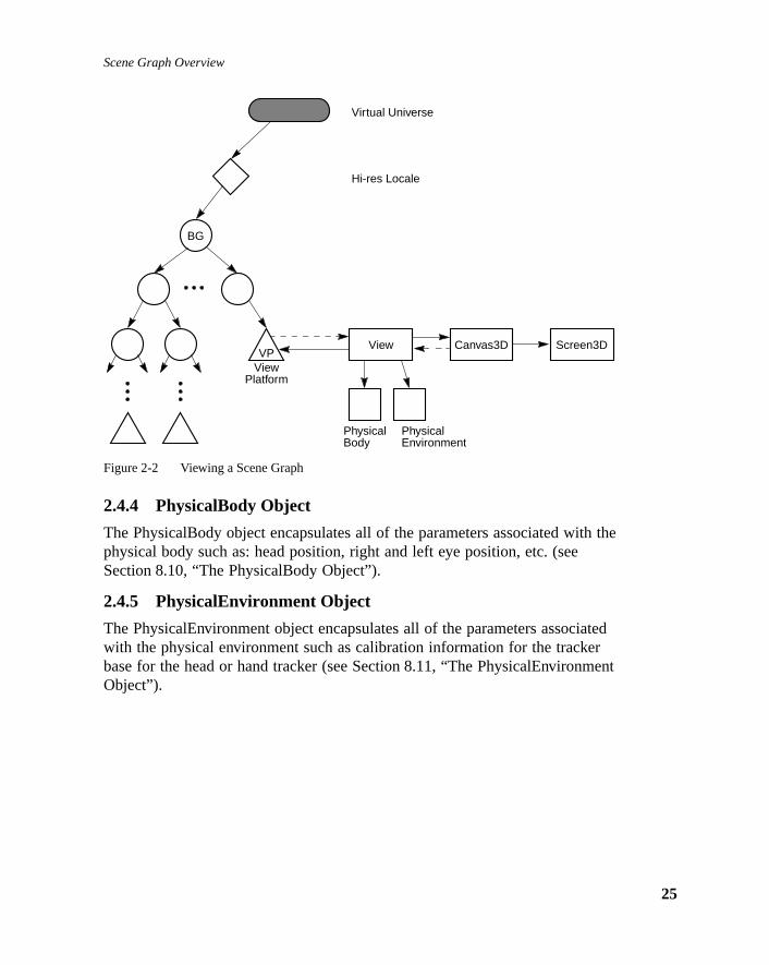
Scene Graph Overview
h the
tedr
ent
Figure 2-2 Viewing a Scene Graph
2.4.4 PhysicalBody Object
The PhysicalBody object encapsulates all of the parameters associated witphysical body such as: head position, right and left eye position, etc. (seeSection 8.10, “The PhysicalBody Object”).
2.4.5 PhysicalEnvironment Object
The PhysicalEnvironment object encapsulates all of the parameters associawith the physical environment such as calibration information for the trackebase for the head or hand tracker (see Section 8.11, “The PhysicalEnvironmObject”).
BG
VPView
Platform
Virtual Universe
Hi-res Locale
View Canvas3D Screen3D
PhysicalBody
PhysicalEnvironment
25

Java 3D API Specification—Version 1.0 August 1, 1997
26

C H A P T E R 3
reach
cene
of
deed,ds.
orelual
that
e of
Scene Graph Superstructu
JAVA 3D’s superstructure consists of one or more VirtualUniverse objects, eof which contains a set of one or more high-resolution Locale objects. TheLocale objects, in turn, contain collections of subgraphs that comprise the sgraph.
3.1 The Virtual UniverseJava 3D defines the concept of avirtual universe as a three-dimensional spacewith an associated set of objects. Virtual universes serve as the largest unitaggregate representation, and can also be thought of as databases. Virtualuniverses can be very large, both in physical space units and in contents. Inin most cases a single virtual universe will serve an application’s entire nee
Virtual universes are separate entities in that no node object may exist in mthan one virtual universe at any one time. Likewise, the objects in one virtuauniverse are not visible in, nor do they interact with objects in, any other virtuniverse.
To support large virtual universes, Java 3D introduces the concept of localeshavehigh-resolution coordinates as an origin. Think of high-resolutioncoordinates as “tie-downs” that precisely anchor the locations of objectsspecified using less-precise floating point coordinates that are within the ranginfluence of the high-resolution coordinates.
27

Java 3D API Specification—Version 1.0 August 1, 1997
28
levelrsess are
igh-
pt
inate
va 3Dttachg withnd isthe
Figure 3-1 The Virtual Universe
A locale, with its associated high-resolution coordinates, serves as the nextof representation down from a virtual universe. For example, all virtual univecontain one or more high-resolution coordinate locales, and all other objectattached to a locale. High-resolution coordinates act as an upper leveltranslation-only transform node. For example, the coordinates of all objectsattached to a particular locale are all relative to the location of that locale’s hresolution coordinate.
While a virtual universe is similar to the traditional computer graphics conceof a scene graph, a given virtual universe can become so large that it is oftenbetter to think of a scene graph as the descendent of a high-resolution coordlocale.
3.2 Establishing a SceneTo construct a three-dimensional scene, the programmer must execute a Japrogram. The Java 3D application must first create a virtual universe and aat least one locale to it. Then the desired scene graph is constructed, startina BranchGroup node and also including at least one ViewPlatform object, aattached to the locale. Finally, a View object is constructed that references
BG BG BG
Virtual Universe
Hi-res Locales
BranchGroup Nodes
Leaf Nodes
Group Nodes

Scene Graph Superstructure
s
pear
at.tual
to or
nand
-esent
0)
more
near
r-
e 1.0
ViewPlatform object (see Section 1.6, “Structuring the Java 3D Program”). Asoon as a scene graph containing a VIewPlatform is attached to theVirtualUniverse, Java 3D’s rendering loop is engaged, and the scene will apon the drawing canvas(es) associated with the View object.
3.3 Loading a Virtual UniverseJava 3D is a run-time API (application programmers interface), not a file formAs an API, Java 3D provides no direct mechanism for loading or storing a viruniverse. Constructing a scene graph involves the execution of a Java 3Dprogram. However, loaders to convert a number of standard 3D file formats from Java 3D virtual universes are expected to be generally available.
3.4 Coordinate SystemsBy default, Java 3D coordinate systems are right handed, with the orientatiosemantics that +Y is the local gravitational up, +X is horizontal to the right, +Z is directly toward the viewer.
By default, Java 3D coordinate systems are in units of meters.
3.5 High Resolution CoordinatesDouble precision floating point, single precision floating point, or even fixedpoint representations of three-dimensional coordinates are sufficient to reprand display rich 3D scenes. Unfortunately, scenes are not worlds, let aloneuniverses. If one ventures even a hundred miles away from the (0.0, 0.0, 0.origin using only single-precision floating-point coordinates, representablepoints become quite quantized, to at very best a third of an inch (and much coarsely than that in practice).
To “shrink” down to a small size (say the size of an IC transistor), even very (0.0, 0.0, 0.0) the same problem arises.
If a large contiguous virtual universe is to be supported, some form of higheresolution addressing is required. Thus the choice of 256-bit positionalcomponents for “high resolution” positions.
3.5.1 Java 3D High-resolution Coordinates
A Java 3D high-resolution coordinate consists of three 256-bit fixed-pointnumbers, one each for x, y, and z. The fixed point is at bit 128 and the valuis defined to be exactly one meter. This coordinate system is sufficient to
29

Java 3D API Specification—Version 1.0 August 1, 1997
30
yet
to
ly
onal. In can
hreethis
xed
ound asary. A
describe a universe in excess of several hundred billion light years across, still define objects smaller than a proton (down to below the planck length).Table 3-1 shows how many bits are needed above or below the fixed point represent the range of interesting physical dimensions.
A 256-bit fixed-point number also has the advantage of being able to directrepresent nearly any reasonable single-precision floating point valueexactly.
High-resolution coordinates in Java 3D are only used to embed more traditifloating point coordinate systems within a much higher resolution substratethis way a visually seamless virtual universe of any conceivable size or scalebe created, without worry about numerical accuracy.
3.5.2 Java 3D Virtual World Coordinates
Within a given virtual world coordinate system, positions are expressed by tfloating point numbers. The virtual world coordinate scale is in meters, but can be affected by scale changes in the object hierarchy.
3.5.3 Details of High-resolution Coordinates
High-resolution coordinates are represented as signed, two's-complement fipoint numbers consisting of 256 bits. Although Java 3D keeps the internalrepresentation of high-resolution coordinates opaque, users specify suchcoordinates using eight-element integer arrays. Java 3D treats the integer fat index 0 as containing the most-significant bits and those found at index 7containing the least-significant bits of the high-resolution coordinate. The binpoint is located at bit position 128 or between the integers at index 3 and 4high-resolution coordinate of 1.0 is 1 meter.
Table 3-1 Java 3D High-resolution Coordinates
2n meters Units
87.29 Universe (20 billion light years)
69.68 Galaxy (100,000 light years)
53.07 Light year
43.43 Solar system diameter
23.60 Earth diameter
10.65 Mile
9.97 Kilometer
0.00 Meter
–19.93 Micron
–33.22 Angstrom
–115.57 Planck length

Scene Graph Superstructure
p togce is
ootally
ed
theode)
, andiveelf the
tsD
ering
angesriatests,
its
The semantics of how file loaders deal with high-resolution coordinates is uthe individual file loader, as Java 3D does not directly define any file loadinsemantics. However, some general advice can be given (note that this advinot officially part of the Java 3D specification).
For “small” virtual universes (order of hundreds of meters across in relativescale), a single high-resolution coordinate at location (0.0, 0.0, 0.0) as the rnode (below the virtual universe object) is sufficient; a loader can automaticconstruct this node during the loading process, and the high-resolutioncoordinate does not need any direct representation in the external file.
For larger virtual universes, it is expected that they will usually be constructlike computer directory hierarchies, e.g. a “root” virtual universe containingmostly external file references to embedded virtual universes. In this case, file reference object (user-specific data hung off a Java 3D group or hi-res ndefines the location for the data to be read into the current virtual universe.
When reading the file, its contents should be parented to the file object nodethus inherit the high-resolution coordinate of the file object as the new relatvirtual universe origin of the embedded scene graph. If this scene graph itscontains high-resolution coordinates, it will need to be offset (translated) byamount in the file object’s high-resolution coordinate, and then added to thelarger virtual universe as new high-resolution coordinates, with their contenhung off below them. Once again, the above is not part of the official Java 3specification, but some more details on the care and use of high-resolutioncoordinates in external file formats will probably be available as a Java 3Dapplication note.
Note for authoring tools directly supporting high-resolution coordinate:authoring tools should create additional high-resolution coordinates as a uscreates new geometry “sufficiently” far away (or of different scale) from existhigh-resolution coordinates.
Semantics of “widely” moving objects. Most fixed and near-fixed objects stayattached to the same high-resolution coordinate. Objects that make wide chin position or scale may need to be periodically re-parented to more approphigh-resolution coordinates. If no appropriate high-resolution coordinate exithe application may need to create a new one.
Semantics of viewing. The view platform object and the associated nodes inhierarchy are very often widely moving objects. Applications will typicallyattach the view platform to the most appropriate high-resolution locale. Fordisplay, all objects will first have their positions translated by the differencebetween the location of their high-resolution locale, and the view platform's
31

Java 3D API Specification—Version 1.0 August 1, 1997
32
no
be
atified
high-resolution locale. (In the common case of the locales being the same,translation is necessary.)
3.6 API for Superstructure Objects
3.6.1 VirtualUniverse Object
The VirtualUniverse object consists of a set of Locale objects.
Constructors
The VirtualUniverse object has the following constructors.
public VirtualUniverse()
This constructs a new VirtualUniverse object. This VirtualUniverse can thenused to create Locale objects.
Methods
The VirtualUniverse object has the following methods.
public Locale getLocale(int index)
Returns the locale specified by the index.
public int numLocales()
Returns the number of locales.
3.6.2 Locale Object
The Locale object consists of a high-resolution coordinate and a set ofsubgraphs, rooted by BranchGroup node objects.
Constructors
The Locale object has the following constructors.
public Locale(VirtualUniverse universe)public Locale(VirtualUniverse universe, int[] x, int[] y,
int[] z)public Locale(VirtualUniverse universe, HiResCoord hiRes)
These three constructors create a new high-resolution Locale object in thespecified VirtualUniverse. The first form constructs a Locale object located (0.0, 0.0, 0.0). The other two forms construct a Locale object using the spechigh-resolution coordinate. In the second form, the parametersx, y, andz arearrays of eight 32-bit integers that specify the high-resolution coordinate.

Scene Graph Superstructure
cale.est
ryact a ascant
eger
-
0).
Methods
public VirtualUniverse getVirtualUniverse()
This method retrieves the virtual universe within which this Locale object iscontained.
public void setHiRes(int[] x, int[] y, int[] z)public void setHiRes(HiResCoord hiRes)public void getHiRes(HiResCoord hiRes)
These methods set or get the high-resolution coordinate of this Locale.
public void addBranchGraph(BranchGroup branchGroup)public void removeBranchGraph(BranchGroup branchGroup)public void replaceBranchGraph(BranchGroup oldGroup,
BranchGroup newGroup)public int numBranchGraphs()public Enumeration getAllBranchGraphs()
The first three methods add, remove, and replace a branch graph in this LoAdding a branch graph has the effect of making the branch graph “live.” Thfourth method retrieves the number of branch graphs in this Locale. The lamethod retrieves an Enumeration object of all branch graphs.
3.6.3 HiResCoord Object
A high-resolution coordinate consists of three two’s-complement fixed-pointnumbers. Each high-resolution number consists of 256 total bits with a binapoint at bit 128. Java 3D uses integer arrays of length eight to define or extrsingle 256-bit coordinate value. Java 3D interprets the integer at index zerothe 32 most-significant bits and the integer at index 7 as the 32 least-signifibits.
Constructors
The HiResCoord object has the following constructors.
public HiResCoord(int[] x, int[] y, int[] z)public HiResCoord(HiResCoord hc)public HiResCoord()
The first constructor generates the high-resolution coordinate from three intarrays of length eight. The integer arrays specify the coordinate valuescorresponding with their name. The second constructor creates a new highresolution coordinate by cloning the high resolution coordinatehc . The thirdconstructor creates a new high-resolution coordinate with value (0.0, 0.0, 0.
33

Java 3D API Specification—Version 1.0 August 1, 1997
34
the
thatgth high-
pdate
gates
Methods
public void setHiResCoord(int[] x, int[] y, int[] z)public void setHiResCoord(HiResCoord hiRes)public void setHiResCoordX(int[] x)public void setHiResCoordY(int[] y)public void setHiResCoordZ(int[] z)
These five methods modify the value of high-resolution coordinatethis . Thefirst method resets all three coordinate values with the values specified by three integer arrays. The second method sets the value ofthis to that of high-resolution coordinatehiRes . The third, fourth, and fifth methods reset thecorresponding coordinate ofthis .
public void getHiResCoord(int[] x, int[] y, int[] z)public void getHiResCoord(HiResCoord hc)public void getHiResCoordX(int[] x)public void getHiResCoordY(int[] y)public void getHiResCoordZ(int[] z)
These five methods retrieve the value of the high-resolution coordinatethis .The first method retrieves the high-resolution coordinate’s value and placesvalue into the three integer arrays specified. All three arrays must have lengreater than or equal to eight. The second method updates the value of theresolution coordinatehc to match the value ofthis . The third, fourth, and fifthmethods retrieve the coordinate value that corresponds to their name and uthe integer array specified, which must be of length eight or greater.
public void add(HiResCoord h1, HiResCoord h2)public void sub(HiResCoord h1, HiResCoord h2)
These two methods perform arithmetic operations on high-resolutioncoordinates. The first method addsh1 to h2 and stores the result inthis . Thesecond method subtractsh2 from h1 and stores the result inthis .
public void scale(int scale, HiResCoord h1)public void scale(int scale)
These methods scale a high resolution coordinate. The first method scalesh1 bythe scalar valuescale and places the scaled coordinate intothis . The secondmethod scalesthis by the scalar valuescale and places the scaled coordinateback intothis .
public void negate(HiResCoord h1)public void negate()
These two methods negate a high resolution coordinate. The first method neh1 and stores the result inthis . The second method negatesthis and stores itsnegated value back intothis .

Scene Graph Superstructure
n
cision
a
tesh the
public void difference(HiResCoord h1, Vector3d v)
This method subtractsh1 from this and stores the resulting difference vector ithe double-precision floating-point vectorv. Note that although the individualhigh-resolution coordinates cannot be represented accurately by double prenumbers, this difference vector between themcan be accurately represented bydoubles for many practical purposes, such as viewing.
public boolean equals(HiResCoord h1)
This method performs an arithmetic comparison betweenthis andh1. It returnsa true if the two high-resolution coordinates are equal, otherwise it returns false.
public double distance(HiResCoord h1)
This method computes the linear distance between high-resolution coordinathis andh1, and returns this value expressed as a double. Note that althougindividual high-resolution coordinates cannot be represented accurately bydouble precision numbers, this distance between themcan be accuratelyrepresented by a double for many practical purposes.
35

Java 3D API Specification—Version 1.0 August 1, 1997
36

C H A P T E R 4
s. Theoupoupindexhender a
ave an:
Group Node Object
GROUP nodes are the glue elements used in constructing a scene graphfollowing subsections list the seven group nodes and their definitions. All grnodes can have a variable number of child node objects—including other grnodes as well as leaf nodes. These children have associated with them an that allows operations to specify a particular child. However, unless one of tspecial ordered group nodes is used, the Java 3D renderer can choose to regroup node’s children in whatever order it wishes (including rendering thechildren in parallel).
Figure 4-1 Group Node Hierarchy
4.1 Group NodeThe Group node object is a general purpose grouping node. Group nodes hexactly one parent and an arbitrary number of children that are rendered inunspecified order (or in parallel). Operations on Group node objects includeadding, removing, and enumerating the children of the Group node. Thesubclasses of Group node add additional semantics.
SceneGraphObjectNode
GroupBranchGroupOrderedGroup
DecalGroupSharedGroupSwitchTransformGroup
37

Java 3D API Specification—Version 1.0 August 1, 1997
38
thod
Thehe
py be
set.
Constants
public static final int ALLOW_CHILDREN_READpublic static final int ALLOW_CHILDREN_WRITEpublic static final int ALLOW_CHILDREN_EXTEND
These flags, when enabled using the setCapability method, specify that thisgroup node will allow the following methods, respectively:
• numChildren, getChild, getAllChildren
• setChild, insertChild, and removeChild
• addChild, moveTo
These capability bits are enforced only when the node is part of a live orcompiled scene graph.
public static final int ALLOW_COLLISION_BOUNDS_READpublic static final int ALLOW_COLLISION_BOUNDS_WRITE
These flags, when enabled using the setCapability method, specify that thisgroup node will allow reading and writing its collision bounds.
Constructors
public Group()
Constructs and initializes a Group node object.
Methods
The Group node class defines the following methods.
public final int numChildren()public final Node getChild(int index)
The first method returns a count of the number of children. The second mereturns the child at the specified index.
public final void setChild(Node child, int index)public final void insertChild(Node child, int index)public final void removeChild(int index)
The first method replaces the child at the specified index with a new child. second method inserts a new child before the child at the specified index. Tthird method removes the child at the specified index. Note that if this grounode is part of a live or compiled scene graph, only BranchGroup nodes maadded to or removed from it—and only if the appropriate capability bits are
public final Enumeration getAllChildren()
This method returns an Enumeration object of all children.

Group Node Objects
sdes
oes
each
theis
des.
as a
ght of
public final void addChild(Node child)
This method adds a new child as the last child in the group. Note that if thigroup node is part of a live or compiled scene graph, only BranchGroup nomay be added to it—and only if the appropriate capability bits are set.
public Node cloneNode(boolean forceDuplicate)
This method duplicates the node as if it were a single entity. This method dnot duplicate children or the parent.
public void duplicateNode(Node originalNode,boolean forceDuplicate)
This method copies all the node information from theoriginalNode into thecurrent node. This method is called from thecloneNode method, which is in turncalled by thecloneTree method.
For any NodeComponent objects contained by the object being duplicated, NodeComponent object'sduplicateOnCloneTree flag is used to determinewhether the NodeComponent should be duplicated in the new node or areference to the current node is placed in the new node. This flag can beoverridden by setting theforceDuplicate parameter in thecloneTree methodto true.
public final void moveTo(BranchGroup branchGroup)
This method moves the specified BranchGroup node from its old location inscene graph to the end of this group, in an atomic manner. Functionally, thmethod is equivalent to:
branchGroup.detach();this.addChild(branchGroup);
If either this group or the specified BranchGroup is part of a live or compilescene graph, the appropriate capability bits must be set in the affected nod
public final Bounds setCollisionBounds(Bounds bounds)public final Bounds getCollisionBounds()
These methods set and retrieve the collision bounding object for a node.
4.2 BranchGroup NodeA BranchGroup is the root of a subgraph of a scene that may be compiled unit, attached to a virtual universe, or included as a child of a group node inanother subgraph. A subgraph, rooted by a BranchGroup node, can be thouas a compile unit. The following things may be done with BranchGroup.
39

Java 3D API Specification—Version 1.0 August 1, 1997
40
sesinednts).
nted4-2.
ome
lityh.
ates
• A BranchGroup may be compiled by calling its compile method. This cauthe entire subgraph to be compiled. If any BranchGroup nodes are contawithin the subgraph, they are compiled as well (along with their descenda
• A BranchGroup may be inserted into a virtual universe by attaching it to aLocale. The entire subgraph is then said to belive.
• A BranchGroup that is contained within another subgraph may be repareor detached at runtime if the appropriate capabilities are set. See Figure
Note that if a BranchGroup is included in another subgraph, as a child of sother group node, it may not be attached to a Locale.
Constants
The BranchGroup class adds the following new constant.
public static final int ALLOW_DETACH
This flag, when enabled using thesetCapability method, allows thisBranchGroup node to be detached from its parent group node. This capabiflag is enforced only when the node is part of a live or compiled scene grap
Methods
The BranchGroup class defines the following methods.
public final void compile()
This method compiles the scene graph rooted at this BranchGroup and creand caches a newly compiled scene graph.
public final void detach()
This method detaches the BranchGroup node from its parent.

Group Node Objects
en itwed
Figure 4-2 Altering the Scene Graph at Runtime
4.3 TransformGroup NodeThe TransformGroup node specifies a single spatial transformation—via aTransform3D object (see Section 7.1.27, “Transform3D Object”)—that canposition, orient, and/or scale all of its children.
The specified transformation must be affine. Further, if the TransformGroupnode is used as an ancestor of a ViewPlatform node in the scene graph, thmust be congruent—only rotations, translations and uniform scales are alloin a direct path from a Locale to a ViewPlatform node. ABadTransformException (see Section D.1, “BadTransformException”) isthrown if an attempt is made to specify an illegal transform.
Note: Even though arbitrary affine transformations are allowed, betterperformance will result if all matrices within a branch graph arecongruent—containing only rotations, translation anduniform scale.
BG
Virtual Universe
Hi-Res Locale
BGCan be reparented orremoved at runtime
BranchGroup Node
41
Java 3D API Specification—Version 1.0 August 1, 1997
42
th
s isointspose of a
dclose
’srt of
es the
by noded
The effects of transformations in the scene graph are cumulative. Theconcatenation of the transformations of each TransformGroup in a direct pafrom the Locale to a Leaf node defines a composite model transformation(CMT) that takes points in that Leaf node’s local coordinates and transformthem into Virtual World (Vworld) coordinates. This composite transformationused to transform points, normals and distances into Vworld coordinates. Pare transformed by the CMT. Normals are transformed by the inverse-transof the CMT. Distances are transformed by the scale of the CMT. In the casetransformation containing a non-uniform scale or shear, the maximum scalevalue in any direction is used. This ensures, for example, that a transformebounding sphere, which is specified as a point and a radius, continues to enall objects that are also transformed by a transformation containing a non-uniform scale.
Constants
The TransformGroup class adds the following new flags.
public static final int ALLOW_TRANSFORM_READpublic static final int ALLOW_TRANSFORM_WRITE
These flags, when enabled using the setCapability method, allow this nodeTransform3D to be read or written. They are only used when the node is paa live or compiled scene graph.
Constructors
public TransformGroup()public TransformGroup(Transform3D t1)
These construct and initialize a new TransformGroup. The first form initializthe node’s Transform3D to the identity transform, the second form initializesnode’s Transform3D to a copy of the specified Transform.
Methods
The TransformGroup class defines the following methods.
public final void setTransform(Transform3D t1)public final void getTransform(Transform3D t1)
These methods retrieve or set this node’s attached Transform3D object bycopying the transform to/from the specified object.
public Node cloneNode(boolean forceDuplicate)public void duplicateNode(Node originalNode, boolean
forceDuplicate)
The first method creates a new instance of the node. This method is calledcloneTree to duplicate the current node. The second method copies all theinformation from theoriginalNode into the current node. This method is callefrom thecloneNode method, which is in turn called by thecloneTree method.

Group Node Objects
each
an be
theirse of
roupothered inde:e, etc.
ren,h of
rstase,
therce
ions
f
For any NodeComponent objects contained by the object being duplicated, NodeComponent object’sduplicateOnCloneTree flag is used to determinewhether the NodeComponent should be duplicated in the new node or areference to the current node should be placed in the new node. This flag coverridden by setting theforceDuplicate parameter in thecloneTree methodto true.
4.4 OrderedGroup NodeThe OrderedGroup node guarantees that Java 3D will render its children in index order. Only the OrderedGroup node (and its subclasses) makes any uthe order of their children during rendering.
4.5 DecalGroup NodeThe DecalGroup node is a subclass of the OrderedGroup node. The DecalGnode is an ordered group node used for defining decal geometry on top of geometry. The DecalGroup node specifies that its children should be renderindex order and that they generate coplanar objects. Examples of this inclupainted decals or text on surfaces, a checkerboard layered on top of a tabl
The first child, at index 0, defines the surface on top of which all other childare rendered. The geometry of this child must encompass all other childrenotherwise incorrect rendering may result. The polygons contained within eacthe children must be facing the same way. If the polygons defined by the fichild are front facing, then all other surfaces should be front facing. In this cthe polygons are rendered in order. The renderer can use knowledge of thecoplanar nature of the surfaces to avoid Z-buffer collisions (e.g., if theunderlying implementation supports stenciling or polygon offset then thesetechniques may be employed). If the main surface is back-facing then all osurfaces should be back facing, and need not be rendered (even if back faculling is disabled).
Note that using the DecalGroup node does not guarantee that Z-buffer collisare avoided. An implementation of Java 3D may fall back to treatingDecalGroup node as an OrderedGroup node.
4.6 Switch NodeThe Switch group node allows a Java 3D application to choose dynamicallyamong a number of subgraphs. The Switch node contains an ordered list o
43
Java 3D API Specification—Version 1.0 August 1, 1997
44
en
.
ndd
icate
L
the
ters.
ctild,
theis
children and a switch value. The switch value determines which child/childrJava 3D will render. Note that the index order of children is only used forselecting the appropriate child/children—it does not specify rendering order
Constants
public static final int ALLOW_SWITCH_READpublic static final int ALLOW_SWITCH_WRITE
These flags, when enabled using the setCapability method, allow reading awriting the values that specify the child selection criteria. They are only usewhen the node is part of a live or compiled scene graph.
public static final int CHILD_NONEpublic static final int CHILD_ALLpublic static final int CHILD_MASK
These values, when used in place of a non-negative integer index value, indwhich children of the Switch node are selected for rendering. A value ofCHILD_NONE indicates that no children are rendered. A value of CHILD_ALindicates that all children are rendered, effectively making this switch nodeoperate as an ordinary group node. A value of CHILD_MASK indicates thatchildMask BitSet is used to select the children that are rendered.
Constructors
public Switch()public Switch(int whichChild)public Switch(int whichChild, BitSet childMask)
These constructors initialize a new switch node using the specified parameThe default values for those parameters not specified are as follows:
whichChild: CHILD_NONEchildMask: empty
Methods
The Switch node class defines the following methods.
public final void setWhichChild(int whichChild)public final int getWhichChild()
These methods access or modify the index of the child that the Switch objewill draw. The value may be a non-negative integer, indicating a specific chor it may be one of the following constants: CHILD_NONE, CHILD_ALL, orCHILD_MASK. If the specified value is out of range then no children aredrawn.
public final void setChildMask(BitSet childMask)public final BitSet getChildMask()
These methods access or modify the mask used to select the children thatSwitch object will draw when the whichChild parameter is CHILD_MASK. Th

Group Node Objects
e
e,
h in
parameter is ignored during rendering if the whichChild parameter is a valuother than CHILD_MASK.
public final Node currentChild()
This method returns the currently selected child. If whichChild is out of rangor is set to CHILD_MASK, CHILD_ALL, or CHILD_NONE, thennull isreturned.
4.7 SharedGroup NodeA SharedGroup node provides a mechanism for sharing the same subgrapdifferent parts of the tree via a Link node. See Section 6.1.1, “SharedGroupNode,” for a description of this node.
45

Java 3D API Specification—Version 1.0 August 1, 1997
46

C H A P T E R 5
The
iew
naft the
Leaf Node Objects
L EAF nodes define atomic entities such as geometry, lights, and sounds. leaf nodes and their associated meaning follow.
5.1 Leaf NodeThe Leaf node is an abstract class for all scene graph nodes which have nochildren. Leaf nodes specify lights, geometry and sounds as well as providespecial linking and instancing capabilities for sharing scene graphs, and a vplatform for positioning and orienting a view in the virtual world. Figure 5-1shows the leaf node object hierarchy.
Constructors
public Leaf()
Constructs and initializes a new Leaf object.
Methods
The Leaf node object defines the following methods.
public void updateNodeReferences(NodeReferenceTablereferenceTable)
This method is called by thecloneTree method (see Section 6.2, “CloningSubgraphs”) after all nodes in the subgraph have been cloned. The user caquery the NodeReferenceTable object to determine if any nodes that the Lenode references have been duplicated by the cloneTree call and, if so, whacorresponding Node is in the new subgraph. If a user extends a predefinedJava 3D object and adds a reference to another node, this method must bedefined in order to ensure proper operation of thecloneTree method. The firststatement in the user’supdateNodeReferences method must besuper.updateNodeReferences(referenceTable) . For predefined Java 3Dnodes, this method will be implemented automatically.
47

Java 3D API Specification—Version 1.0 August 1, 1997
48
tole
des,
oonent.
The NodeReferenceTable object is passed to theupdateNodeReferences
method and allows for references from the old subgraph to be translated inreferences in the cloned subgraph. See Section 6.2.5, “NodeReferenceTabObject,” for more details.
Figure 5-1 Leaf Node Hierarchy
public Node cloneTree(boolean forceDuplicate)
This method duplicates all nodes of the specified sub-graph. For Group Nothe group node is first duplicated via a call tocloneNode and thencloneTree iscalled for each child node. For Leaf Nodes, component data can either beduplicated or be made a reference to the original data. Leaf NodecloneTree
behavior is determined by theduplicateOnCloneTree flag found in every LeafNode’s component data class and by theforceDuplicate parameter.
5.2 Shape3D NodeThe Shape3D leaf node object specifies all geometric objects. It contains twcomponents: a reference to the shape’s geometry and its appearance comp
SceneGraphObjectNode
LeafBackgroundBehavior
Pre-defined behaviorsBoundingLeafClipFog
ExponentialFogLinearFog
LightAmbientLightDirectionalLightPointLight
SpotLightLinkMorphShape3DSound
BackgroundSoundPointSound
ConeSoundSoundscapeViewPlatform

Leaf Node Objects
objectre,
de is
ifieddry
ed
iated
The Geometry object defines the shape’s geometric data. The Appearance specifies that object’s appearance attributes, including color, material, textuand so on.
Constants
The Shape3D node object defines the following flags.
public static final int ALLOW_GEOMETRY_READpublic static final int ALLOW_GEOMETRY_WRITEpublic static final int ALLOW_APPEARANCE_READpublic static final int ALLOW_APPEARANCE_WRITEpublic static final int ALLOW_COLLISION_BOUNDS_WRITEpublic static final int ALLOW_COLLISION_BOUNDS_READ
These flags, when enabled using thesetCapability method, allow reading andwriting the Geometry and Appearance component objects and the collisionbounds, respectively. These capability flags are enforced only when the nopart of a live or compiled scene graph.
Constructors
The Shape3D node object defines the following constructors.
public Shape3D(Geometry geometry, Appearance appearance)public Shape3D(Geometry geometry)public Shape3D()
The first form constructs and initializes a new Shape3D object with the specgeometry and appearance components. The second form uses the specifiegeometry and a default appearance. The third form specifies a null geometcomponent and a default appearance.
Methods
The Shape3D node object defines the following methods.
public final void setGeometry(Geometry geometry)public final Geometry getGeometry()
These methods access or modify the Geometry component object associatwith this Shape3D node.
public final void setAppearance(Appearance appearance)public final Appearance getAppearance()
These methods access or modify the Appearance component object assocwith this Shape3D node.
public final void setCollisionBounds(Bounds bounds)public final Bounds getCollisionBounds()
These methods set and retrieve the collision bounds for this node.
49

Java 3D API Specification—Version 1.0 August 1, 1997
50
icate
each
st aan be
naft the
tole
ncednnglocalaf
public Node cloneNode(boolean forceDuplicate)
This method duplicates the node as if it were a single entity. It does not duplthe children or parent information.
public void duplicateNode(Node originalNode,boolean forceDuplicate)
This method copies all the node information from theoriginalNode into thecurrent node. This method is called from thecloneNode method, which is in turncalled by thecloneTree method.
For any NodeComponent objects contained by the object being duplicated, NodeComponent object'sduplicateOnCloneTree flag is used to determinewhether the NodeComponent should be duplicated in the new node or if jureference to the current node should be placed in the new node. This flag coverridden by setting theforceDuplicate parameter in thecloneTree methodto true.
public void updateNodeReferences(NodeReferenceTablereferenceTable)
This method is called by thecloneTree method (see Section 6.2, “CloningSubgraphs”) after all nodes in the subgraph have been cloned. The user caquery the NodeReferenceTable object to determine if any nodes that the Lenode references have been duplicated by the cloneTree call and, if so, whacorresponding Node is in the new subgraph. If a user extends a predefinedJava 3D object and adds a reference to another node, this method must bedefined in order to ensure proper operation of thecloneTree method. The firststatement in the user’supdateNodeReferences method must besuper.updateNodeReferences(referenceTable) . For predefined Java 3Dnodes, this method will be implemented automatically.
The NodeReferenceTable object is passed to theupdateNodeReferences
method and allows for references from the old subgraph to be translated inreferences in the cloned subgraph. See Section 6.2.5, “NodeReferenceTabObject,” for more details.
5.3 BoundingLeaf NodeThe BoundingLeaf node defines a bounding region object that can be refereby other leaf nodes to define a region of influence (Fog and Light nodes), aactivation region (Background, Clip, and Soundscape nodes), or a scheduliregion (Sound and Behavior nodes). The bounding region is defined in the coordinate system of the BoundingLeaf node. A reference to a BoundingLenode can be used in place of a locally defined bounds object for any of theaforementioned regions.

Leaf Node Objects
temlf how
lightlocalthe
them of
ject.ing
ew is
hethe
This allows an application to specify a bounding region in one coordinate sys(the local coordinate system of the BoundingLeaf node) other than the locacoordinate system of the node that references the bounds. For an example othis might be used, consider a closed room with a number track lights. Eachcan move independently from the other lights and, as such, needs its own coordinate system. However, the bounding volume used by all the lights in boundary of the room, which doesn’t move when the lights move. In thisexample, the BoundingLeaf node allows the bounding region to be defined inlocal coordinate system of the room, rather than in the local coordinate systea particular light. All lights can then share this single bounding volume.
Constants
The BoundingLeaf node object defines the following flags.
public static final int ALLOW_REGION_READpublic static final int ALLOW_REGION_WRITE
These flags, when enabled using thesetCapability method, allow anapplication to invoke methods that respectively read and write the boundingregion object.
Constructors
The BoundingLeaf node object defines the following constructors.
public BoundingLeaf()Public BoundingLeaf(Bounds region)
The first form constructs a BoundingLeaf node with a unit sphere region obThe second form constructs a BoundingLeaf node with the specified boundregion.
Methods
public final void setRegion(Bounds region)public final Bounds getRegion()
These methods set and retrieve the BoundingLeaf node’s bounding region.
5.4 Background NodeThe Background leaf node defines either a solid background color or abackground image that is used to fill the window at the beginning of each nframe. It also specifies an application region in which this Background nodeactive. A Background node is active when its application region intersects tViewPlatform’s activation volume. If multiple Background nodes are active, Background node that is “closest” to the eye will be used. If no Backgroundnodes are active, then the window is cleared to black.
51

Java 3D API Specification—Version 1.0 August 1, 1997
52
netry.
ck
s not
the
Constants
The Background node object defines the following flags.
public static final int ALLOW_APPLICATION_BOUNDS_READpublic static final int ALLOW_APPLICATION_BOUNDS_WRITEpublic static final int ALLOW_IMAGE_READpublic static final int ALLOW_IMAGE_WRITEpublic static final int ALLOW_COLOR_READpublic static final int ALLOW_COLOR_WRITEpublic static final int ALLOW_GEOMETRY_READpublic static final int ALLOW_GEOMETRY_WRITE
These flags, when enabled using thesetCapability method, allow anapplication to invoke methods that respectively read and write the applicatioregion, the image, and write the image, the color, and the background geomThese capability flags are enforced only when the node is part of a live orcompiled scene graph.
Constructors
The Background node object defines the following constructors.
public Background()public Background(Color3f color)public Background(float r, float g, float b)public Background(PixelArray2D image)
The first form constructs a Background leaf node with a default color of bla(0.0,0.0,0.0). The next two forms construct a Background leaf node with thespecified color. The final form constructs a Background leaf node with thespecified 2D image.
Methods
The Background node object defines the following methods.
public final void getColor(Color3f color)public final void setColor(Color3f color)public final void setColor(float r, float g, float b)
These three methods access or modify the background color.
public final ImageComponent2D getImage()public final void setImage(ImageComponent2D image)
These two methods access or modify the background image. If the image inull then it is used in place of the color.
public final void setGeometry(BranchGroup branch)public final BranchGroup getGeometry()
These two methods access or modify the Background geometry. ThesetGeometry method sets the background geometry to the specifiedBranchGroup node. If non-null, this background geometry is drawn on top of

Leaf Node Objects
eere.
gion.bject.
unds.
e is
ified
hed.
de.m of
background color or image using a projection matrix that essentially puts thgeometry at infinity. The geometry should be pre-tessellated onto a unit sph
public final void setApplicationBoundingLeaf(BoundingLeaf region)public final BoundingLeaf getApplicationBoundingLeaf()
These two methods access or modify the Background node’s application reWhen set to a value other than null, this overrides the application bounds o
public final void setApplicationBounds(Bounds region)public final Bounds getApplicationBounds()
These two methods access or modify the Background nodes application boThis is used when the application bounding leaf is set to null. ThegetApplicationBounds method returns a new Bounds object.
5.5 Clip NodeThe Clip leaf node defines the far clipping plane used to clip objects in thevirtual universe. It also specifies an application region in which this Clip nodactive. A Clip node is active when its application region intersects theViewPlatform’s activation volume. If multiple Clip nodes are active, the Clipnode that is “closest” to the eye will be used. The back distance value specby this Clip node overrides the value specified in the View object. If no Clipnodes are active, then the back clip distance is used from the View object.
Constructors
The Clip node object defines the following constructor.
public Clip(float backDistance)public Clip()
The first constructor constructs a Clip leaf node with the rear clip plane at tspecified distance, in the local coordinate system, from the eye. The seconconstructor constructs a Clip leaf node with a default back clipping distance
Methods
The Clip node object defines the following methods.
public final void setBackDistance(double backDistance)public final double getBackDistance()
These methods access or modify the back clipping distances in the Clip noThis distance specifies the back clipping plane in the local coordinate systethe node.
53

Java 3D API Specification—Version 1.0 August 1, 1997
54
Clip
n set
s thatter
veFogpe of
n of
m
,gs
public final void setApplicationBounds(Bounds region)public final Bounds getApplicationBounds()
These methods access and modify the Clip node’s application bounds. Thenode is active when its application region intersects the ViewPlatform’sactivation volume. ThegetApplicationBounds method returns a new Boundsobject.
public final void setApplicationBoundingLeaf(BoundingLeaf region)public final BoundingLeaf getApplicationBoundingLeaf()
These methods access and modify the Clip node’s application region. Wheto a value other than null, this overrides the application bounds object.
5.6 Fog NodeThe Fog leaf node is an abstract class that defines a common set of attributecontrol fog, or depth cueing, in the scene. The Fog node includes a paramethat specifies the fog color and a Bounds object that specifies the region ofinfluence for the Fog node.
Objects whose bounding volume intersects the Fog’s region of influence hafog applied to their color after lighting and texturing have been applied. The node also contains a list of Group nodes that indicates the hierarchical scothis fog. If the list of scoping nodes is empty, the fog hasuniverse scope and willapply to all nodes in the virtual universe that are within the Fog node’s regioinfluence.
If the regions of influence of multiple Fog nodes overlap, the Java 3D systewill choose a single set of fog parameters for those objects that lie in theintersection. This is done in an implementation-dependent manner, but ingeneral, the Fog node that is “closest” to the object is chosen.
Constants
The Fog node object defines the following flags.
public static final int ALLOW_INFLUENCING_BOUNDS_READpublic static final int ALLOW_INFLUENCING_BOUNDS_WRITEpublic static final int ALLOW_COLOR_READpublic static final int ALLOW_COLOR_WRITE
These flags, when enabled using thesetCapability method, allow anapplication to invoke methods that respectively read the region of influencewrite the region of influence, read color, and write color. These capability flaare enforced only when the node is part of a live or compiled scene graph.
Constructors
The Fog node object defines the following constructors.

Leaf Node Objects
sesfiedlues
will
ged
et to
fault,o beof a
public Fog()public Fog(float r, float g, float b)public Fog(Color3f color)
These constructors each construct a new Fog node. The first constructor udefault values for all parameters. The remaining constructors use the speciparameters and use defaults for those parameters not specified. Default vaare as follows:
color: black (0,0,0)list of scoping nodes: emptyinfluencingRegion: empty
Methods
The Fog node object defines the following methods.
public final void setColor(float r, float g, float b)public final void setColor(Color3f color)public final void getColor(Color3f color)
These three methods access or modify the Fog node’s color. An applicationtypically set this to the same value as the background color.
public final setInfluencingBounds(Bounds region)public final Bounds getInfluencingBounds()
These methods access or modify the Fog node’s influencing region. The Fonode operates on all objects that intersect the specified Bounds. This is uswhen the influencing bounding leaf is set to null. ThegetInfluencingBounds
method returns a new Bounds object.
public final setInfluencingBoundingLeaf(BoundingLeaf region)public final getInfluencingBoundingLeaf()
These methods access or modify the Fog node’s influencing region. When sa value other than null, this overrides the influencing bounds object.
public final void setScope(Group scope)public final Group getScope()public final void addScope(Group scope)public final void insertScope(Group scope, int index)public final void removeScope(int index)public final int numScopes()public final Enumeration getAllScopes()
These methods access or modify the Fog node’s hierarchical scope. By deFog nodes are scoped only by their regions of influence. This allows them tfurther scoped by a Group node in the hierarchy. The hierarchical scoping Fog node may not be accessed or modified if the node is part of a live orcompiled scene graph.
55

Java 3D API Specification—Version 1.0 August 1, 1997
56
nsity
ctual
lues.
orscified.
ject.
anceally
oftes.
5.6.1 ExponentialFog Node
The ExponentialFog leaf node extends the Fog leaf node by adding a fog dethat is used as the exponent of the fog equation.
The density is defined in the local coordinate system of the node, but the afog equation will ideally take place in eye coordinates.
Constants
The ExponentialFog node object defines the following flags.
public static final int ALLOW_DENSITY_READpublic static final int ALLOW_DENSITY_WRITE
These flags, when enabled using thesetCapability method, allow anapplication to invoke methods that respectively read and write the density vaThese capability flags are enforced only when the node is part of a live orcompiled scene graph.
Constructors
The ExponentialFog node object defines the following constructors.
public ExponentialFog()public ExponentialFog(float r, float g, float b)public ExponentialFog(Color3f color)public ExponentialFog(float r, float g, float b, float density)public ExponentialFog(Color3f color, float density)
Each of these constructors create a new ExponentialFog node. The firstconstructor uses default values for all parameters. The remaining constructuse the specified parameters and use defaults for those parameters not speDefault values are as follows:
density: 1.0
Methods
The ExponentialFog node object defines the following methods.
public final void setDensity(float density)public final float getDensity()
These two methods access or modify the density in the ExponentialFog ob
5.6.2 LinearFog Node
The LinearFog leaf node extends the Fog leaf node by adding a pair of distvalues, in Z, at which fog should start obscuring the scene and should maximobscure the scene.
The front and back fog distances are defined in the local coordinate systemthe node, but the actual fog equation will ideally take place in eye coordina

Leaf Node Objects
ve or
ctor
efault
to allor
Constants
The LinearFog node object defines the following flags.
public static final int ALLOW_DISTANCE_READpublic static final int ALLOW_DISTANCE_WRITE
These flags, when enabled using thesetCapability method, allow anapplication to invoke methods that respectively read and write the distancevalues. These capability flags are enforced only when the node is part of a licompiled scene graph.
Constructors
The LinearFog node object defines the following constructors.
public LinearFog()public LinearFog(float r, float g, float b)public LinearFog(Color3f color)public LinearFog(float r, float g, float b, double frontDistance,
double backDistance)public LinearFog(Color3f color, double frontDistance,
double backDistance)
These constructors each construct a new LinearFog node. The first construuses default values for all parameters. The remaining constructors use thespecified parameters and use defaults for those parameters not specified. Dvalues are as follows:
front distance: 0.1back distance: 1.0
Methods
The LinearFog node object defines the following methods.
public final void setFrontDistance(float frontDistance)public final float getFrontDistance()public final void setBackDistance(float backDistance)public final float getBackDistance()
These four methods access or modify the front and back distances in theLinearFog object. The front distance is the distance at which the fog startsobscuring objects. The back distance is the distance at which the fog fullyobscures objects. Objects drawn closer than the front fog distance are notaffected by fog. Objects drawn farther than the back fog distance are drawnentirely in the fog color.
5.7 Light NodeThe Light leaf node is an abstract class that defines the properties commonLight nodes. A light has associated with it a color, a state (whether it is on
57

Java 3D API Specification—Version 1.0 August 1, 1997
58
nce the
hasthe
odel.
d
ht is
ighted
off), and a Bounds object that specifies the region of influence for the light.Objects whose bounding volume intersects the Light node’s region of influeare lit by this light. The Light node also contains a Group node that indicateshierarchical scope of this light. If no scoping node is specified, then the lightuniverse scope and applies to all nodes in the virtual universe that are within light’s region of influence.
The Java 3D lighting model is based on a subset of the OpenGL lighting m
Constants
The Light node object defines the following flags.
public static final int ALLOW_INFLUENCING_BOUNDS_READpublic static final int ALLOW_INFLUENCING_BOUNDS_WRITEpublic static final int ALLOW_STATE_READpublic static final int ALLOW_STATE_WRITEpublic static final int ALLOW_COLOR_READpublic static final int ALLOW_COLOR_WRITE
These flags, when enabled using thesetCapability method, allow reading andwriting the region of influence, the state, and the color, respectively. Thesecapability flags are enforced only when the node is part of a live or compilescene graph.
Constructors
The Light node object defines the following constructors.
public Light()public Light(Color3f color)public Light(boolean lightOn, Color3f color)
These three constructors construct and initialize a light.
Methods
The Light node object defines the following methods.
public final void setEnable(boolean state)public final boolean getEnable()
These methods access or modify the state of this light (i.e., whether the ligenabled).
public final void setColor(Color3f color)public final void getColor(Color3f color)
These methods access or modify the current color of this light.
public final setInfluencingBounds(Bounds region)public final Bounds getInfluencingBounds()
These methods access or modify the Light node’s influencing region. The Lnode operates on all objects that intersect the specified Bounds. This is us

Leaf Node Objects
set
fault,ws
utes
ng
as
when the influencing bounding leaf is set to null. ThegetInfluencingBounds
method returns a new Bounds object.
public final setInfluencingBoundingLeaf(BoundingLeaf region)public final getInfluencingBoundingLeaf()
These methods access or modify the Light node’s influencing region. Whento a value other than null, this overrides the influencing bounds object.
public final void setScope(Group scope)public final Group getScope()public final void addScope(Group scope)public final void insertScope(Group scope, int index)public final void removeScope(int index)public final int numScopes()public final Enumeration getAllScopes()
These methods access or modify the Light node’s hierarchical scope. By deLight nodes are scoped only by their regions of influence bounds. This allothem to be further scoped by a node in the hierarchy.
5.7.1 AmbientLight Node
An AmbientLight node defines an ambient light source. It has the same attribas the abstract Light node.
Constructors
The AmbientLight node defines the following constructors.
public AmbientLight()public AmbientLight(Color3f color)public AmbientLight(boolean lightOn, Color3f color)
The first constructor constructs and initializes a new AmbientLight node usidefault parameters. The next two constructors construct and initialize a newAmbientLight node using the specified parameters. Thecolor parameter is thecolor of the light source. ThelightOn flag indicates whether this light is on oroff.
5.7.2 DirectionalLight Node
A DirectionalLight node defines an oriented light with an origin at infinity. It hthe same attributes as a Light node with the addition of a direction vector tospecify the direction in which it shines.
Constants
The DirectionalLight node object defines the following flags.
59

Java 3D API Specification—Version 1.0 August 1, 1997
60
live
em
t is
ters
and
de.
public static final int ALLOW_DIRECTION_READpublic static final int ALLOW_DIRECTION_WRITE
These flags, when enabled using thesetCapability method, allow anapplication to invoke methods that respectively read or write the associateddirection. These capability flags are enforced only when the node is part of aor compiled scene graph.
The DirectionalLight’s direction vector is defined in the local coordinate systof the node.
Constructors
The DirectionalLight node object defines the following constructors.
public DirectionalLight()
Constructs and initializes a directional light. The default direction of the lightoward the screen, along the negative z axis.
public DirectionalLight(Color3f color, Vector3f direction)public DirectionalLight(boolean LightOn, Color3f color,
Vector3f direction)
These constructors construct and initialize a directional light with the parameprovided.
Methods
The DirectionalLight node object defines the following methods.
public final void setDirection(Vector3f direction)public final void setDirection(float x, float y, float z)public final void getDirection(Vector3f direction)
These methods access or modify the light’s current direction.
5.7.3 PointLight Node
A PointLight node defines a point light source located at some point in spaceradiating light in all directions (also known as apositional light). It has the sameattributes as a Light node with the addition of a location and attenuationparameters.
The PointLight’s position is defined in the local coordinate system of the no
Constants
The PointLight node object defines the following flags.

Leaf Node Objects
read flags
luesial
andodeits,
public static final int ALLOW_POSITION_READpublic static final int ALLOW_POSITION_WRITEpublic static final int ALLOW_ATTENUATION_READpublic static final int ALLOW_ATTENUATION_WRITE
These flags, when enabled using thesetCapability method, allow anapplication to invoke methods that respectively read position, write position, attenuation parameters, and write attenuation parameters. These capabilityare enforced only when the node is part of a live or compiled scene graph.
Constructors
The PointLight Node defines the following constructors.
public PointLight()
Constructs and initializes a point light source with the default position at0.0, 0.0, 0.0.
public PointLight(Color3f color, Point3f position, Point3fattenuation)
public PointLight(boolean lightOn, Color3f color, Point3fposition, Point3f attenuation)
These methods construct and initialize a point light with the specifiedparameters.
Methods
The PointLight node object defines the following methods.
public final void setPosition(Point3f position)public final void setPosition(float x, float y, float z)public final void getPosition(Point3f position)
These methods access or modify the point light’s current position.
public final void setAttenuation(Point3f attenuation)public final void setAttenuation(float constant, float linear,
float quadratic)public final void getAttenuation(Point3f attenuation)
These methods access or modify the point light’s current attenuation. The vapresented to the methods specify the coefficients of the attenuation polynomwith constant providing the constant term,linear providing the linearcoefficient, andquadratic providing the quadratic coefficient.
5.7.4 SpotLight Node
A SpotLight node defines a point light source located at some point in spaceradiating in a specific direction. It has the same attributes as a PointLight nwith the addition of a direction of radiation, a spread angle to specify its limand a concentration factor that specifies how quickly the light intensity
61

Java 3D API Specification—Version 1.0 August 1, 1997
62
ction
read are
ight.
attenuates as a function of the angle of radiation as measured from the direof radiation.
Constants
The SpotLight node object defines the following flags.
public static final int ALLOW_SPREAD_ANGLE_READpublic static final int ALLOW_SPREAD_ANGLE_WRITEpublic static final int ALLOW_CONCENTRATION_READpublic static final int ALLOW_CONCENTRATION_WRITEpublic static final int ALLOW_DIRECTION_READpublic static final int ALLOW_DIRECTION_WRITE
These flags, when enabled using thesetCapability method, allow anapplication to invoke methods that respectively read and write spread angle,and write concentration, and read and write direction. These capability flagsenforced only when the node is part of a live or compiled scene graph.
The SpotLight’s direction vector and spread angle are defined in the localcoordinate system of the node.
Constructors
The SpotLight node object defines the following constructors.
public SpotLight()
Constructs and initializes a new spot light with the default values.
public SpotLight(Color3f color, Point3f position,Point3f attenuation, Vector3f direction,float spreadAngle, float concentration)
public SpotLight(boolean lightOn, Color3f color,Point3f position, Point3f attenuation,Vector3f direction, float spreadAngle,float concentration)
Constructs and initializes a new spot light with the parameters specified.
Methods
The SpotLight node object defines the following methods.
public final void setSpreadAngle(float spreadAngle)public final float getSpreadAngle()
These methods access or modify the spread angle, in radians, of this spotl
public final void setConcentration(float concentration)public final float getConcentration()
These methods access or modify the concentration of this spotlight.

Leaf Node Objects
alleacheasewhenether is to
.
ta,ous theags
public final void setDirection(float x, float y, float z)public final void setDirection(Vector3f direction)public final void getDirection(Vector3f direction)
These methods access or modify the direction of this spotlight.
5.8 Sound NodeThe Sound node is an abstract class that defines the properties common tosound nodes. A scene graph can contain multiple sounds. Associated with sound source are: reference to sound data, an amplitude scale factor, a relflag denoting that the sound associated with this node is to play to the end it is disabled, the number of times the sound is to be repeated, a state (whthe sound is on or off), a scheduling region, and a flag denoting if the soundcontinue playing “silently” even while it is inactive. Whenever the listener iswithin the sound node’s scheduling bounds, the sound is potentially audible
Constants
The Sound object contains the following flags.
public static final int ALLOW_SOUND_DATA_READpublic static final int ALLOW_SOUND_DATA_WRITEpublic static final int ALLOW_INITIAL_GAIN_READpublic static final int ALLOW_INITIAL_GAIN_WRITEpublic static final int ALLOW_LOOP_READpublic static final int ALLOW_LOOP_WRITEpublic static final int ALLOW_RELEASE_READpublic static final int ALLOW_RELEASE_WRITEpublic static final int ALLOW_CONT_PLAY_READpublic static final int ALLOW_CONT_PLAY_WRITEpublic static final int ALLOW_ENABLE_READpublic static final int ALLOW_ENABLE_WRITEpublic static final int ALLOW_SCHEDULING_BOUNDS_READpublic static final int ALLOW_SCHEDULING_BOUNDS_WRITEpublic static final int ALLOW_PRIORITY_READpublic static final int ALLOW_PRIORITY_WRITEpublic static final int ALLOW_DURATION_READpublic static final int ALLOW_IS_PLAYING_READ
These flags, when enabled using thesetCapability method, allow anapplication to invoke methods that respectively read and write the sound dathe initial gain information, the loop information, the release flag, the continuplay flag, the sound on/off switch, the scheduling region, prioritization value,duration information, and the sound playing information. These capability flare enforced only when the node is part of a live or compiled scene graph.
Constructors
The Sound node object defines the following constructors.
63

Java 3D API Specification—Version 1.0 August 1, 1997
64
ing
and
ion
eter
ayers
licitly
be
this
public Sound()
Constructs and initializes a new Sound node object that includes the followdefaults for its fields:
sound data: nullinitial gain: 1.0loop: 0release flag: falsecontinuous flag: falseon switch: falsescheduling region: null (cannot be scheduled)priority: 1.0
public Sound(MediaContainer soundData, float initialGain)
Constructs and initializes a new Sound node object using the provided datagain parameter values, and defaults for all other fields. This constructorimplicitly loads the sound data associated with this node if the implementatuses sound caching.
public Sound(MediaContainer soundData, float initialGain,int loopCount, boolean release, boolean continuous,boolean enable, Bounds region, float priority)
Constructs and initializes a new Sound node object using the provided paramvalues.
Methods
The Sound node object defines the following methods.
public final void setSoundData(MediaContainer soundData)public final MediaContainer getSoundData()
These methods provide a way to associate different types of Java Media Plcontaining audio data with a SoundNode. This data can be cached or non-cached, and the non-cached data can be streaming or not. This method exploads a sound if the implementation uses sound data caching, or it makesstreaming data audible. While all supported types of MediaContainers can associated with a non-spatialized Sound node, only specific types can bespatialized.
public final void setInitialGain(float amplitude)public final float getInitialGain()
This gain is a scale factor that is applied to the sound data associated withsound source to increase or decrease its overall amplitude.
Leaf Node Objects
opof
e
not thehethese
re itunds–1
he
dataing.
ecksnds theing
on. A
ng
public final void setLoop(int loopCount)public final int getLoop()
Data for non-streaming sound (such as a sound sample) can contain two lopoints marking a section of the data that is to be looped a specific number times. Thus sound data can be divided into three segments: theattack (before thebegin loop point), thesustain (between the begin and end loop points), and threlease (after the end loop point). If there are no loop begin and end pointsdefined as part of the sound data (say for Java Media Player types that do contain sound samples) then the begin loop point is set at the beginning ofsound data, and the end loop point at the end of the sound data. If this is tcase, looping the sound would mean repeating the whole sound. However, begin and end loop points can be placed anywhere within the sound data,allowing a portion in the middle of the sound to be looped.
A sound can be looped a specified number of times after it is activated befois completed. The loop count value explicitly sets the number of times the sois looped. Any non-negative number is a valid value. A value of zero denotethat the looped section is not repeated, but is played only once. A value of denotes that the loop is repeated indefinitely.
public final void setReleaseEnable(boolean state)public final boolean getReleaseEnable()
When a sound is disabled, its playback would normally stop immediately nomatter what part of the sound data was currently being played. By setting tRelease flag to true for nodes with non-streaming sound data, the sound isallowed to play from its current position in the sound data to the end of the (without repeats) thus playing the release portion of the sound before stopp
public final void setContinuousEnable(boolean state)public final boolean getContinuousEnable()
For some applications, it’s useful to turn a sound source “off” but to continu“silently” playing the sound so that when it is turned back “on” the sound piup playing in the same location (over time) as it would have been if the souhad never been disabled (turned off). Setting the Continuous flag true causesound renderer to keep track of where (over time) the sound would be playeven when the sound is disabled.
public final setSchedulingBounds(Bounds region)public final Bounds getSchedulingBounds()
These methods access or modify the Sound node’s scheduling bounds regiSound is scheduled for activation when its scheduling region intersects theViewPlatform’s activation volume. This is used when the scheduling boundileaf is set to null. ThegetSchedulingBounds method returns a new Boundsobject.
65

Java 3D API Specification—Version 1.0 August 1, 1997
66
af.bject.
rankorendle,
whennd
dently
gain
starts istiong or
le the
ng, thend
oting
itss
public final void setSchedulingBoundingLeaf(BoundingLeaf region)public final BoundingLeaf getSchedulingBoundingLeaf()
These methods access or modify the Sound node’s scheduling bounding leWhen set to a value other than null, this overrides the scheduling bounds o
public final void setPriority(float ranking)public final float getPriority()
These methods access or modify the Sound node’s priority. This is used toconcurrently playing sounds in order of importance during playback. When msounds are started than the device driver or physical playback device can hathe sound node with the lowest priority ranking is deactivated. If a sound isdeactivated (due to a sound with a higher priority being started) it isautomatically re-activated when output resources becomes available (e.g., a sound with a higher priority finishes playing), or when the ordering of sounodes are changed due to a change in a sound nodes priority. A method todetermine what audio output resources are required for playback of a Sounnode on a particular AudioDevice, as well as a method to determine the curravailable audio output resources can be queried with AudioDevice methodsdescribed in Chapter 11, “Audio Devices.”
public final void setEnable(boolean state)public final boolean getEnable()
These two methods access or modify the playing state of this sound (i.e.,whether the sound is enabled). When enabled, the sound source is startedplaying and thus can potentially be heard, depending on its activation state,control parameters, continuation state, and spatiallization parameters. If thecontinuous state is true, even if the sound is not active, enabling the sound the sound silently “playing,” so that when the sound is activated, the sound(potentially) heard from somewhere in the middle of the sound data. Activastate can change from active to inactive any number of times without stoppinstarting the sound. To re-start a sound at the beginning of its data, re-enabsound by callingsetEnable with true.
public final boolean isPlaying()
A sound source will not be heard unless it is both enabled (turned on) andactivated. After a sound source has been enabled and thus has begun playiend of the sound could be reached before the sound is disabled, or the soucould be deactivated without being stopped. This method returns a flag denif the sound is actually playing and thus is potentially audible.
public final long getDuration()
This method returns the length of time in millisecond the sound mediaassociated with the sound source could run (including the number of times loop section is repeated) if it plays to completion. If the sound media type i

Leaf Node Objects
ource. This
dd
tes asce-
.
tenerf.
l
ndde is
streaming, or if the sound is looped indefinitely, then a value of –1 (implyinginfinite length) is returned.
5.8.1 BackgroundSound Node
A BackgroundSound node defines an unattenuated, non-spatialized sound sthat has no position or direction. It has the same attributes as a Sound nodetype of sound is simply added to the sound mix without modification and isuseful for playing a mono or stereo music track, or playing an ambient souneffect. Unlike a Background (visual) node, more than one BackgroundSounnode can be simultaneously enabled and active.
Constructors
The BackgroundSound node specifies the following constructor.
public BackgroundSound()
This constructs and initializes a new BackgroundSound node.
5.8.2 PointSound Node
The PointSound node defines a spatially-located sound whose waves radiauniformly in all directions from some point in space. It has the same attributea Sound object with the addition of a location and the specification of distanbased gain attenuation for listener positions between an array of distances
The sound’s amplitude is attenuated based on the distance between the lisand the sound source position. A piecewise linear curve (defined in terms opairs of distance and gain scale factor) specifies the gain scale factor slope
The PointSound’s location and attenuation distances are defined in the locacoordinate system of the node.
Constants
The PointSound object contains the following flags:
public static final int ALLOW_POSITION_READpublic static final int ALLOW_POSITION_WRITEpublic static final int ALLOW_DISTANCE_GAIN_READpublic static final int ALLOW_DISTANCE_GAIN_WRITE
These flags, when enabled using thesetCapability method, allow anapplication to invoke methods that respectively read and write the position athe distance gain array. These capability flags are enforced only when the nopart of a live or compiled scene graph.
Constructors
The PointSound node object defines the following constructors.
67

Java 3D API Specification—Version 1.0 August 1, 1997
68
he
rs ashe
idedition.ts ofr the and a
e
public PointSound()
Constructs a PointSound node object that includes the defaults for a Soundobject plus the following defaults for its own fields:
position vector: (0.0, 0.0, 0.0)Back attenuation: nulldistance gain attenuation: null (no attenuation performed)
public PointSound(MediaContainer soundData, float initialGain,Point3f position)
public PointSound(MediaContainer soundData, float initialGain,float posX, float posY, float posZ)
Both of these constructors construct a PointSound node object using only tprovided parameter values for sound data, sample gain, and position. Theremaining fields are set to the above default values. The first form uses vectoinput for its position. The second form uses individual float parameters for telements of the position vector.
public PointSound(MediaContainer soundData, float initialGain,int loopCount, boolean release, boolean continuous,boolean enable, Bounds region, float priority,Point3f position, Point2f[] distanceGain)
public PointSound(MediaContainer soundData, float initialGain,int loopCount, boolean release, boolean continuous,boolean enable, Bounds region, float priority,float posX, float posY, float posZ,Point2f[] distanceGain)
public PointSound(MediaContainer soundData, float initialGain,int loopCount, boolean release, boolean continuous,boolean enable, Bounds region, float priority,Point3f position, float[] attenuationDistance,float[] attenuationGain)
public PointSound(MediaContainer soundData, float initialGain,int loopCount, boolean release, boolean continuous,boolean enable, Bounds region, float priority,float posX, float posY, float posZ,float[] attenuationDistance, float[] attenuationGain)
These four constructors construct a PointSound node object using the provparameter values. The first and third forms use vectors as input for the posThe second and fourth forms use individual float parameters for the elementhe position vector. The first and second forms accept an array of Point2f fodistance attenuation values where each pair in the array contains a distancegain scale factor. The third and fourth forms accept separate arrays for thedistance and gain scale factors components of distance attenuation. See thdescription for thesetDistanceGain method, below, for details on how theseparate arrays are interpreted.

Leaf Node Objects
und
ot set,in of
hain-linearurrent
Methods
The PointSound node object defines the following methods.
public final void setPosition(Point3f position)public final void setPosition(float x, float y, float z)public final void getPosition(Point3f position)
These methods set and retrieve the position in 3D space from which the soradiates.
public final void setDistanceGain(Point2f[] attenuation)public final void setDistanceGain(float[] distance, float[] gain)public final int getDistanceGainLength()public final void getDistanceGain(Point2f[] attenuation)public final void getDistanceGain(float[] distance, float[] gain)
These methods set and retrieve the sound’s distance attenuation. If this is nno distance gain attenuation is performed (equivalent to using a distance ga1.0 for all distances). See Figure 5-2. Gain scale factors are associated witdistances from the listener to the sound source via an array of (distance, gscale-factor) pairs. The gain scale factor applied to the sound source is the interpolated gain value between the distance value range that includes the cdistance from the listener to the sound source.
Figure 5-2 PointSound Distance Gain Attenuation
1.0
0.5
0.0
10 20 300Distance (from listenerto sound source)
Scale Factor
69

Java 3D API Specification—Version 1.0 August 1, 1997
70
tanceeatesly
ce.
e
ofin
lly
in
scalecef 1.0
enere
be at
If the distance from the listener to the sound source is less than the first disin the array, the first gain scale factor is applied to the sound source. This cra spherical region around the listener within which all sound gain is uniformscaled by the first gain in the array.
If the distance from the listener to the sound source is greater than the lastdistance in the array, the last gain scale factor is applied to the sound sour
The first form ofsetDistanceGain takes these pairs of values as an array ofPoint2f. The second form accepts two separate arrays for these values. Thdistance andgainScale arrays should be of the same length. If thegainScale
array length is greater than thedistance array length, thegainScale arrayelements beyond the length of the distance array are ignored. If thegainScale
array is shorter than thedistance array, the lastgainScale array value isrepeated to fill an array of length equal todistance array.
There are two methods forgetDistanceGain , one returning an array of points,the other returning separate arrays for each attenuation component.
Distance elements in this array of Point2f is a monotonically-increasing set floating point numbers measured from the location of the sound source. Gascale factors elements in this list of pairs can be any positive floating pointnumbers. While for most applications this list of gain scale factors will usuabe monotonically-decreasing, they do not have to be.
Figure 5-2 shows a graphical representation of an example of a distance gaattenuation list. The values given for distance-gain pairs would be:
( (10.0, 1.0), (12.0, 0.9), (16.0, 0.5), (17.0, 0.3), (20.0, 0.16), (24.0, 0.12), (28.0, 0.05), (30.0, 0.0) )
So if the current distance from the listener to the sound source is 22 units, afactor of 0.14 would be applied to the sound amplitude. If the current distanfrom the listener to the sound source is less than 10 units, the scale factor owould be applied to the sound amplitude. If the current distance from the listto the sound source is greater than 30 units, the scale factor of 0.0 would bapplied to the sound amplitude.
getDistanceGainLength method returns the length of the distance gainattenuation arrays. Arrays passed into getDistanceGain methods should allleast this size.
public final void setSoundData(MediaContainer soundData)
This method sets fields that define the sound source data of this node. Thismethod differs from the Sound node method, in that it calls thePointSoundRetained version of this method.

Leaf Node Objects
d.
rce isd bye
on isund
lnt
of a
lter
e
ance
public final void setEnable(boolean state)
This method enables or disables sound. This method differs from the Sounnode method, in that it calls the PointSoundRetained version of this method
5.8.3 ConeSound Node
The ConeSound node object defines a PointSound node whose sound soudirected along a specific vector in space. A ConeSound source is attenuategain scale factors and filters based on the angle between the vector from thsource to the listener, and the ConeSound’s direction vector. This attenuatieither a single spherical distance gain attenuation (as for a general PointSosource) or dual front and back distance gain attenuations (defining ellipticaattenuation areas. The angular filter and the active AuralAttribute componefilter define what filtering is applied to the sound source (see Section 5.8.2,“PointSound Node”).
This node has the same attributes as a PointSound node with the addition direction vector and an array of points each containing: angular distance (inradians), gain scale factor, and filter (which for now consists of a lowpass ficutoff frequency). Similar to the definition of the distance gain array forPointSounds, a piece-wise linear curve (defined in terms of radians from thaxis) specifies the slope of these additional attenuation values.
Figure 5-3 shows an approximation of angular attenuation (disregarding distattenuation).
Figure 5-3 ConeSound
DistanceGain[1]
angularAttenuation[3]
angularAttenuation[0]
Sound direction (axis)
Attenuated values
Distance gain[0]
71

Java 3D API Specification—Version 1.0 August 1, 1997
72
and node
ound
heion.sal
ion,
Constants
The ConeSound object contains the following flags:
public static final int ALLOW_DIRECTION_READpublic static final int ALLOW_DIRECTION_WRITEpublic static final int ALLOW_ANGULAR_ATTENUATION_READpublic static final int ALLOW_ANGULAR_ATTENUATION_WRITE
These flags, when enabled using thesetCapability method, allow anapplication to invoke methods that respectively read and write the directionangular attenuation array. These capability flags are enforced only when theis part of a live or compiled scene graph.
Constructors
The ConeSound node object defines the following constructors.
public ConeSound()
Constructs a ConeSound node object that includes the defaults for a PointSobject plus the following defaults for its own fields:
Direction vector: (0.0, 0.0, 1.0)Angular attenuation:
((0.0, 1.0), Sound.NO_FILTER,(π/2, 0.0, Sound.NO_FILTER))
public ConeSound(MediaContainer soundData, float initialGain,Point3f position, Vector3f direction)
public ConeSound(MediaContainer soundData, float initialGain,float posX, float posY, float posZ, float dirX,float dirY, float dirZ)
Both of these constructors construct a ConeSound node object using only tprovided parameter values for sound, overall initial gain, position, and directThe remaining fields are set to the default values above. The first form usepoints as input for its position and direction. The second form uses individufloat parameters for the elements of the position and direction vectors.
public ConeSound(MediaContainer soundData, float initialGain,int loopCount, boolean release, boolean continuous,boolean enable, Bounds region, float priority,Point3f position, Point2f[] frontDistanceAttenuation,Point2f[] backDistanceAttenuation, Vector3f direction)
public ConeSound(MediaContainer soundData, float initialGain,int loopCount, boolean release, boolean continuous,boolean enable, Bounds region, float priority,float posX, float posY, float posZ,float[] frontDistance, float[] frontDistanceGain,float[] backDistance, float[] backDistanceGain,float dirX, float dirY, float dirZ)
These constructors construct a ConeSound node object using the providedparameter values. The first form uses points or vectors as input for its posit

Leaf Node Objects
o
ne
on
ain
in the
ay.lend
tion,
ular
y
actorstance,
ce
direction, and front/back distance attenuation arrays. The second form usesindividual float parameters for the elements of the position, direction and twdistance attenuation arrays.
Unlike the single distance gain attenuation array for PointSounds which defispherical areas about the sound source between which gains are linearlyinterpolated, this directed ConeSound can have two distance gain attenuatiarrays that define ellipsoidal attenuation areas. See thesetDistanceGain
PointSound method for details on how the separate distance and distanceGarrays are interpreted.
The ConeSound’s direction vector and angular measurements are defined local coordinate system of the node.
public ConeSound(MediaContainer soundData, float initialGain,int loopCount, boolean release, boolean continuous,boolean enable, Bounds region, float priority,Point3f position, Point2f[] distanceAttenuation,Vector3f direction, Point3f[] angularAttenuation)
public ConeSound(MediaContainer soundData, float initialGain,int loopCount, boolean release, boolean continuous,boolean enable, Bounds region, float priority,float posX, float posY, float posZ, float[] distance,float[] distanceGain, float dirX, float dirY, float dirZ,float innerConeAngle, float outerConeAngle, float angle,float angularGain, float[] frequencyCutoff)
These constructors construct a ConeSound node object using the providedparameter values, which include a single spherical distance attenuation arrThe first form uses point and vectors as input for its position, direction, singspherical distanceAttenuation array, and angularAttenuation array. The secoform uses individual float parameters for the elements of the position, direcdistanceAttenuation array, and angularAttenuation array.
The first form accepts arrays of points for the distance attenuation and angvalues. Each Point2f in thedistanceAttenuation array contains a distance anda gain scale factor. Each Point3f in theangularAttenuation array contains anangular distance, a gain scale factor, and a filtering value (which is currentldefined as a simple cutoff frequency).
The second form accepts separate arrays for the distance and gain scale fcomponents of distance attenuation, and separate arrays for the angular disangular gain, and filtering components of angular attenuation. See thesetDistanceGain ConeSound method for details on how the separate distanand distanceGain arrays are interpreted. See thesetAngularAttenuation
ConeSound method for details on how the separate angularDistance,angularGain, and filter arrays are interpreted.
73

Java 3D API Specification—Version 1.0 August 1, 1997
74
s ass
of
ce
If this
isk
public ConeSound(MediaContainer soundData, float initialGain,int loopCount, boolean release, boolean continuous,boolean enable, Bounds region, float priority,Point3f position, Point2f[] frontDistanceAttenuation,Point2f[] backDistanceAttenuation, Vector3f direction,Point3f[] angularAttenuation)
public ConeSound(MediaContainer soundData, float initialGain,int loopCount, boolean release, float priority,boolean continuous, boolean enable, Bounds region,float posX, float posY, float posZ,float[] frontDistance, float[] frontDistanceGain,float[] backDistance, float[] backDistanceGain,float dirX, float dirY, float dirZ, float angle,float angularGain, float[] frequencyCutoff)
These constructors construct a ConeSound node object using the providedparameter values, which include two distance attenuation arrays definingelliptical distance attenuation regions. The first form uses points and vectorinput for its position, direction, and attenuation arrays. The second form useindividual float parameters for these same elements.
These two methods differ from the above two methods only in the definitionthe two distinct front and back distance attenuation arrays. See thesetDistanceGain ConeSound method for details on how the separate distanand distanceGain arrays are interpreted. See thesetAngularAttenuation
ConeSound method for details on how the separate angularDistance,angularGain, and filter arrays are interpreted.
Methods
The ConeSound node object defines the following methods.
public final void setDistanceGain(Point2f[] frontAttenuation,Point2f[] backAttenuation)
public final void setDistanceGain(float[] frontDistance,float[] frontGain, float[] backDistance,float[] backGain)
public final void setBackDistanceGain(Point2f[] attenuation)public final void setBackDistanceGain(float[] distance,
float[] gain)public final void getDistanceGain(Point2f[] frontAttenuation,
Point2f[] backAttenuation)public final void getDistanceGain(float[] frontDistance,
float[] frontGain, float[] backDistance,float[] backGain)
These methods set and retrieve the cone sound’s two distance attenuation. is not set, no distance gain attenuation is performed (equivalent to using adistance gain of 1.0 for all distances). If only one distance attenuation arrayset, sphere attenuation is assumed (see Figure 5-4). If both a front and bacdistance attenuation are set, elliptical attenuation regions are defined (see

Leaf Node Objects
ance
snce
thest beual to
undhevaluee
Figure 5-5). Use PointSound setDistanceGain() method to set the front distattenuation array separate from the back distance attenuation array.
Figure 5-4 ConeSound with a Single Distance Gain Attenuation Array
Figure 5-5 ConeSound with Two Distance Gain Attenuation Arrays
A front distance attenuation array defines monotonically increasing distancefrom the sound source origin along the position direction vector. A back distaattenuation array (if given) defines monotonically increasing distances fromsound source origin along the negative direction vector. The two arrays muof the same length. The backDistance[i] gain values must be less than or eqfrontDistance[i] gain values.
Gain scale factors are associated with distances from the listener to the sosource via an array of (distance, gain-scale-factor) pairs - see Figure 5-2. Tgain scale factor applied to the sound source is the linear interpolated gain between the distance value range that includes the current distance from thlistener to the sound source.
Listener
DistancesSoundsource
Angular distances
Listener
Back distances Front distances
75

Java 3D API Specification—Version 1.0 August 1, 1997
76
f the. size.
ion. Ifnt to
of anglee
pliedce
d'sel the
tionr and
f
hilelly-
are
getDistanceGainLength method defined for PointSound returns the length oall distance gain attenuation arrays, including the back distance gain arraysArrays passed into getBackDistanceGain methods should all be at least this
public final void setDirection(Vector3f direction)public final void setDirection(float x, float y, float z)public final void getDirection(Vector3f direction)
This value is the sound source’s direction vector. It is the axis from whichangular distance is measured.
public final void setAngularAttenuation(Point2f[] attenuation)public final void setAngularAttenuation(Point3f[] attenuation)public final void setAngularAttenuation(float[] angle,
float[] angularGain, float[] frequency Cutoff)public final int getAngularAttenuationLength()public final void getAngularAttenuation(Point3f[] attenuation)public final void getAngularAttenuation(float[] angle,
float[] angularGain, float[] frequency Cutoff)
These methods set and retrieve the sound’s angular gain and filter attenuatthis is not set, no angular gain attenuation or filtering is performed (equivaleusing an angular gain scale factor of 1.0 and an angular filter ofSound.NO_FILTER for all distances). This attenuation is defined as a triple(angular distance, gain-scale-factor, filter). The distance is measured as thein radians between the ConeSound's direction vector and the vector from thsound source position to the listener. Both the gain scale factor and filter apto the sound source is the linear interpolation of values between the distanvalue range that includes the angular distance from the sound source axis.
If the angular distance from the listener-sound-position vector and the soundirection vector is less than the first distance in the array, the first gain scalfactor and first filter are applied to the sound source. This creates a conicaregion around the listener within which the sound is uniformly attenuated byfirst gain and the first filter in the array.
If the distance from the listener-sound-position vector and the sound's direcvector is greater than the last distance in the array, the last gain scale factolast filter are applied to the sound source.
Distance elements in this array of points is a monotonically-increasing set ofloating point numbers measured from 0 toπ radians. Gain scale factorselements in this list of points can be any positive floating point numbers. Wfor most applications this list of gain scale factors will usually be monotonicadecreasing, they do not have to be. The filter (for now) is a single simplefrequency cutoff value.
In the first form ofsetAngularAttenuation , only the angular distances andangular gain scale factors pairs are given. The filter values for these tuples
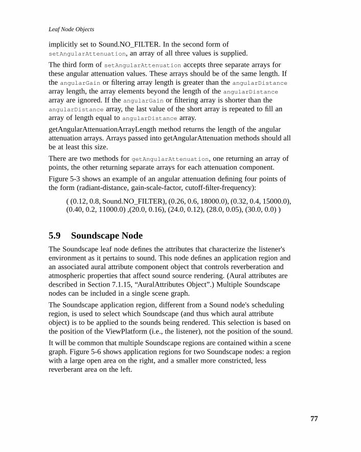
Leaf Node Objects
th. If
rld all
.
of
.0),)
er's andnd are
ing
ed onund.
ceneegion
implicitly set to Sound.NO_FILTER. In the second form ofsetAngularAttenuation , an array of all three values is supplied.
The third form ofsetAngularAttenuation accepts three separate arrays forthese angular attenuation values. These arrays should be of the same lengthe angularGain or filtering array length is greater than theangularDistance
array length, the array elements beyond the length of theangularDistance
array are ignored. If theangularGain or filtering array is shorter than theangularDistance array, the last value of the short array is repeated to fill anarray of length equal toangularDistance array.
getAngularAttenuationArrayLength method returns the length of the angulaattenuation arrays. Arrays passed into getAngularAttenuation methods shoube at least this size.
There are two methods forgetAngularAttenuation , one returning an array ofpoints, the other returning separate arrays for each attenuation component
Figure 5-3 shows an example of an angular attenuation defining four pointsthe form (radiant-distance, gain-scale-factor, cutoff-filter-frequency):
( (0.12, 0.8, Sound.NO_FILTER), (0.26, 0.6, 18000.0), (0.32, 0.4, 15000(0.40, 0.2, 11000.0) ,(20.0, 0.16), (24.0, 0.12), (28.0, 0.05), (30.0, 0.0)
5.9 Soundscape NodeThe Soundscape leaf node defines the attributes that characterize the listenenvironment as it pertains to sound. This node defines an application regionan associated aural attribute component object that controls reverberation aatmospheric properties that affect sound source rendering. (Aural attributesdescribed in Section 7.1.15, “AuralAttributes Object”.) Multiple Soundscapenodes can be included in a single scene graph.
The Soundscape application region, different from a Sound node's schedulregion, is used to select which Soundscape (and thus which aural attributeobject) is to be applied to the sounds being rendered. This selection is basthe position of the ViewPlatform (i.e., the listener), not the position of the so
It will be common that multiple Soundscape regions are contained within a sgraph. Figure 5-6 shows application regions for two Soundscape nodes: a rwith a large open area on the right, and a smaller more constricted, lessreverberant area on the left.
77

Java 3D API Specification—Version 1.0 August 1, 1997
78
theirg on
nn the
r its
cation
Figure 5-6 Multiple Soundscape Application Regions
The reverberation attributes for these two regions could be set to representphysical differences so that active sounds are rendered differently dependinwhich region the listener is in.
Constants
The Soundscape node object defines the following flags.
public static final int ALLOW_APPLICATION_BOUNDS_READpublic static final int ALLOW_APPLICATION_BOUNDS_WRITEpublic static final int ALLOW_ATTRIBUTES_READpublic static final int ALLOW_ATTRIBUTES_WRITE
These flags, when enabled using thesetCapability method, allow anapplication to invoke methods that respectively read and write the applicatioregion and the aural attributes. These capability flags are enforced only whenode is part of a live or compiled scene graph.
Constructors
The Soundscape node object defines the following constructors.
public Soundscape()
Constructs a Soundscape node object that includes the following defaults foelements:
application region: null (no active region)aural attributes: null (uses default aural attributes)
public Soundscape(Bounds region, AuralAttributes attributes)
This method constructs a Soundscape node object using the specified appliregion and aural attributes.
Application Region 2Application Region 1

Leaf Node Objects
regionesn this
ndingn
e.
by as inointenetes
che or
Methods
The Soundscape node object defines the following methods.
public final void setApplicationBounds(Bounds region)public final Bounds getApplicationBounds()
These two methods access or modify the Soundscape's application bounds specified in the local coordinate system of this leaf node. The aural attributassociated with this Soundscape are used to render the active sounds wheapplication region intersects the ViewPlatform’s activation volume. ThegetApplicationBounds method returns a new Bounds object.
public final void setApplicationBoundingLeaf(BoundingLeaf region)public final BoundingLeaf getApplicationBoundingLeaf()
These methods access and modify the Soundscape node’s application bouleaf region. When set to a value other than null, this overrides the applicatiobounds object.
public final void setAuralAttributes(AuralAttributes attributes)public final AuralAttributes getAuralAttributes()
These two methods access or modify the aural attributes of this Soundscap
5.10 ViewPlatform NodeThe ViewPlatform node object defines a viewing platform that is referenced View object. The location, orientation, and scale of the composite transformthe scene graph from the root to the ViewPlatform specifies where the viewpis located and which direction it is pointing. Changing the transform in the scgraph hierarchy above the ViewPlatform is the way in which a viewer navigathrough the Virtual Universe.
Constants
The ViewPlatform node object defines the following flags.
public static final int ALLOW_POLICY_READpublic static final int ALLOW_POLICY_WRITE
These flags, when enabled using thesetCapability method, allow anapplication to invoke methods that respectively read and write the view attapolicy. These capability flags are enforced only when the node is part of a livcompiled scene graph.
Methods
The ViewPlatform node object defines the following methods:
79

Java 3D API Specification—Version 1.0 August 1, 1997
80
f theonsse
a set. Ifs the
ulingbe
e
ee
e for
atlred byand
arrayph
public final void setActivationRadius(float activationRadius)public final float getActivationRadius()
The activation radius defines an activation volume surrounding the center oViewPlatform. This activation volume is intersected with the scheduling regiand application regions of other leaf node objects to determine which of thoobjects may affect rendering.
Different leaf objects interact with the ViewPlatform’s activation volumedifferently. The Background, Clip, and Soundscape leaf objects each defineof attributes and an application region in which those attributes are appliedmore than one node of a given type (Background, Clip, or Sound) intersectViewPlatform’s activation volume, the “most appropriate” node is selected.
Sound leaf objects begin playing their associated sounds when their Schedvolume intersects a ViewPlatform’s activation volume. Multiple sounds may active at the same time.
Behavior objects act somewhat differently. Those behavior objects withscheduling regions that intersect a ViewPlatform’s activation volume becomcandidates for scheduling. Effectively, a ViewPlatform’s activation volumebecomes an additional qualifier on the scheduling of all Behavior objects. SChapter 10, “Behaviors, Interpolators, and Picking,” for more details.
public final void setViewAttachPolicy(int policy)public final int getViewAttachPolicy()
The view attach policy determines how Java 3D places the user’s virtual eypoint as a function of head position. See Section 8.4.3, “View Attach Policy,”details.
5.11 Behavior NodeThe Behavior leaf node allows an application to manipulate a scene graph runtime. Behavior is an abstract class that defines properties common to albehavior objects in Java 3D. There are several predefined behaviors that asubclasses of Behavior. Additionally, a Behavior leaf node may be subclassethe user. Behaviors are described in Chapter 10, “Behaviors, Interpolators, Picking.”
5.12 Morph NodeThe Morph leaf node permits an application to morph between multipleGeometryArrays. The morph node contains a single Appearance node, an of GeometryArray objects, and an array of corresponding weights. The mor

Leaf Node Objects
achfy
ph
ode.t,
by
node combines these GeometryArrays into an aggregate shape based on eGeometryArray’s corresponding weight. Typically, Behavior nodes will modithe weights to achieve various morphing effects.
Constants
The Morph node specifies the following flags:
public static final int ALLOW_GEOMETRY_ARRAY_READpublic static final int ALLOW_GEOMETRY_ARRAY_WRITEpublic static final int ALLOW_APPEARANCE_READpublic static final int ALLOW_APPEARANCE_WRITEpublic static final int ALLOW_WEIGHTS_READpublic static final int ALLOW_WEIGHTS_WRITEpublic static final int ALLOW_COLLISION_BOUNDS_READpublic static final int ALLOW_COLLISION_BOUNDS_WRITE
These flags, when enabled using thesetCapability method, allow anapplication to invoke methods that respectively read and write theGeometryArrays, appearance, weights, and collision Bounds components.
Constructors
The Morph node specifies the following constructors.
public Morph(GeometryArray geometryArrays[])public Morph(GeometryArray geometryArrays[],
Appearance appearance)
Construct and initialize a Morph leaf node.
Methods
The Morph node specifies the following methods.
public final void setGeometryArrays(GeometryArraygeometryArrays[])
public final GeometryArray getGeometryArray()
These methods set and retrieve the geometryArrays component of the Mornode. The GeometryArray component specifies colors, normals, and texturecoordinates.
public final void setAppearance(Appearance appearance)public final Appearance getAppearance()
These methods set and retrieve the appearance component of this Morph nThe appearance component specifies material, texture, texture environmentransparency or other rendering parameters.
public void setWeights(double weights[])public double[] getWeights()
These methods set and retrieve the morph weight vector component of thisMorph node. The Morph node “weights” the corresponding GeometryArray the amount specified.
81

Java 3D API Specification—Version 1.0 August 1, 1997
82
otedber
“Link
public final void setCollisionBounds(Bounds bounds)public final Bounds getCollisionBounds()
These methods set and retrieve the collision bounding object of this node.
5.13 Link NodeThe Link leaf node allows an application to reference a shared subgroup, roby a SharedGroup node, from within a branch of the scene graph. Any numof Link nodes can refer to the same SharedGroup node. See Section 6.1.2, Leaf Node,” for a description of this node.
C H A P T E R 6
sgraph.ille firsthen one
ene
d
(see
affect
ing
ode
Reusing Scene Graph
JAVA 3D provides application programmers with two different means forreusing scene graphs. First, multiple scene graphs can share a common subSecond, the node hierarchy of a common subgraph can be cloned, while stsharing large component objects such as geometry and texture objects. In thcase, changes in the shared subgraph affect all scene graphs that refer to tshared subgraph. In the second case, each instance is unique—a change iinstance does not affect any other instance.
6.1 Sharing SubgraphsAn application that wishes to share a subgraph from multiple places in a scgraph must do so through the use of the Link leaf node and an associatedSharedGroup node. The SharedGroup node serves as the root of the sharesubgraph. The Link leaf node refers to the SharedGroup node. It does notincorporate the shared scene graph directly into its scene graph.
6.1.1 SharedGroup Node
A SharedGroup node allows multiple Link leaf nodes to share its subgraph Figure 6-1) according to the following semantics:
• A SharedGroup may be referenced by one or more Link leaf nodes. Anyruntime changes to a node or component object in this shared subgraph all graphs that refer to this subgraph.
• A SharedGroup may be compiled by calling its compile method prior to bereferenced by any Link leaf nodes.
• Only Link leaf nodes may refer to SharedGroup nodes. A SharedGroup nmay not have parents nor may it be attached to a Locale.
83

Java 3D API Specification—Version 1.0 August 1, 1997
84
only
ar
Figure 6-1 Sharing a Subgraph
A shared subgraph may contain any group node, except an embeddedSharedGroup node (SharedGroup nodes may not have parents). However, the following Leaf nodes may appear in a shared subgraph:
• Light
• Link
• Morph
• Shape
• Sound
An IllegalSharingException is thrown if any of the following Leaf nodes appein a shared subgraph:
BG
Virtual Universe
Hi-Res Locale
BG
L
SG
Link Nodes
SharedGroup Node
BranchGroup Nodes
L

Reusing Scene Graphs
and
d by Seenode.
ation
the
nts to
• Background
• Behavior
• Clip
• Fog
• Soundscape
• ViewPlatform
Methods
The SharedGroup node defines the following method.
public final void compile()
This method compiles the source SharedGroup associated with this object creates and caches a newly compiled scene graph.
6.1.2 Link Leaf Node
The Link leaf node allows an application to reference a shared graph, rootea SharedGroup node, from within a branch graph or another shared graph.Figure 6-1. Any number of Link nodes can refer to the same SharedGroup
Constants
The Link node object defines two flags.
public static final int ALLOW_SHARED_GROUP_READpublic static final int ALLOW_SHARED_GROUP_WRITE
These flags, when enabled using the setCapability method, allow an applicto invoke methods that respectively read and write the SharedGroup nodepointed to by this Link node. These capability flags are enforced only whennode is part of a live or compiled scene graph.
Constructors
The Link node object defines two constructors.
public Link()public Link(SharedGroup sharedGroup)
The first form constructs a Link node object that does not yet point to aSharedGroup node. The second form constructs a Link node object that poithe specified SharedGroup node.
Methods
The Link node object defines two methods.
85

Java 3D API Specification—Version 1.0 August 1, 1997
86
this
reatehe
, and typeush
te
.1,
a.
ee,
ng
public final void setSharedGroup(SharedGroup sharedGroup)public final SharedGroup getSharedGroup()
These methods access and modify the SharedGroup node associated withLink leaf node.
6.2 Cloning SubgraphsAn application developer may wish to reuse a common subgraph withoutcompletely sharing that subgraph. For example, the developer may wish to ca parking lot scene consisting of multiple cars, each with a different color. Tdeveloper might define three basic types of cars, such as convertible, trucksedan. To create the parking lot scene, the application will instantiate eachof car several times. Then the application can change the color of the varioinstances to create more variety in the scene. Unlike shared subgraphs eacinstance is a separate copy of the scene graph definition—changes to oneinstance do not affect any other instance.
Java 3D provides thecloneTree method for this purpose. ThecloneTree
method allows the programmer to change some attributes (NodeComponenobjects) in a scene graph, while at the same time, sharing the majority of thscene graph data—the geometry.
Methods
public Node cloneTree()public Node cloneTree(boolean forceDuplicate)public Node cloneTree(boolean forceDuplicate,
boolean allowDanglingReferences)
These methods start the cloning of the subgraph. The optionalforceDuplicate
parameter, when set totrue , causes Leaf NodeComponent objects to ignoretheir duplicateOnCloneTree value and always be duplicated (see Section 6.2“References To Node Component Objects”). TheallowDanglingReferences
parameter, when set totrue , will permit the cloning of a subgraph even when dangling reference is generated (see Section 6.2.3, “Dangling References”)SettingforceDuplicate andallowDanglingReferences to false is theequivalent of callingcloneTree without any parameters. This will result in NodComponent objects being either duplicated or referenced in the cloned nodbased on theirduplicateOnCloneTree value and aDanglingReferenceException to be thrown if a dangling reference isencountered.
When thecloneTree method is called on a node, that node is duplicated alowith all of its internal state. Then, if the node is a Group node,cloneTree iscalled on each of the node’s children.

Reusing Scene Graphs
re,
.ginalange at
theta
aredh.
The cloneTree method cannot be called on a live or compiled scene graph.
6.2.1 References To Node Component Objects
WhencloneTree reaches a Leaf node, there are two possible actions forhandling the Leaf node's NodeComponent objects (such as Material, Textuetc.). First, the cloned Leaf node can reference the original Leaf node’sNodeComponent object—the NodeComponent object itself is not duplicatedSince the cloned Leaf node shares the NodeComponent object with the oriLeaf node, changing the data in the NodeComponent object will effect a chin both nodes. This mode would also be used for objects that are read-onlyruntime.
Alternatively, the NodeComponent object can be duplicated, in which case new Leaf node would reference the duplicated object. This mode allows dareferenced by the newly-created leaf node to be modified without thatmodification affecting the original leaf node.
In Figure 6-2, for example, two instances of NodeComponent objects are shwhile one NodeComponent element was duplicated for the cloned subgrap
Figure 6-2 Referenced and Duplicated NodeComponent Objects
G
Leaf Nodes
Group Nodes
LfLfLf
NodeComponents
CloneTree
G
LfLfLf
87

Java 3D API Specification—Version 1.0 August 1, 1997
88
s
t be
s
nce a
still
by a
ncedtheir
Methods
public final void setDuplicateOnCloneTree(boolean)public final void getDuplicateOnCloneTree()
These methods set a flag that controls whether a NodeComponent object iduplicated or referenced on a call tocloneTree .
By default this flag is false, meaning that the NodeComponent object will noduplicated on a call tocloneTree —newly created leaf nodes will refer to theoriginal NodeComponent object.
If the cloneTree method is called with theforceDuplicate parameter set totrue , theduplicateOnCloneTree flag is ignored and the entire scene graph iduplicated.
6.2.2 References to Other Scene Graph Nodes
Leaf nodes that contain references to other nodes (e.g., Light nodes refereGroup node) can create a problem for thecloneTree method. After thecloneTree operation is performed the reference in the cloned Leaf node willrefer to the node in the original subgraph – a situation that is most likelyincorrect (Figure 6-3).
Figure 6-3 References to Other Scene Graph Nodes
To handle these ambiguities, a callback mechanism is provided.
A Leaf node that needs to update referenced nodes upon being duplicatedcall to cloneTree must implement theupdateNodeReferences method. Byusing this method, the cloned Leaf node can determine if any nodes refereby it have been duplicated and, if so, update the appropriate references to cloned counterparts.
G
Lf1LfLf
G
Lf2LfLf
cloneTreeN1 N2

Reusing Scene Graphs
e
ce
objectsnd, if aod
Suppose, for instance, that the Leaf node Lf1 in Figure 6-3 implemented thupdateNodeReferences method. Once all nodes had been duplicated, thecloneTree method would then call each cloned Leaf’s nodeupdateNodeReferences method. When cloned Leaf node Lf2’s method wascalled, Lf2 could ask if the Node N1 had been duplicated during thecloneTree
operation. If the node had been duplicated, Leaf Lf2 could then update itsinternal state with the cloned Node, N2 (see Figure 6-4).
Figure 6-4 Updated Subgraph After updateNodeReferences Call
All predefined Java 3D nodes will automatically have theirupdateNodeReferences method defined. Only subclassed nodes that referenother nodes need to have this method overridden by the user.
Methods
public void updateNodeReferences(NodeReferenceTablereferenceTable)
This Leaf node method is called by thecloneTree method after all nodes in thesubgraph have been cloned. The user can query the NodeReferenceTable (see Section 6.2.5, “NodeReferenceTable Object”) to determine if any Nodethat the Leaf node references have been duplicated by the cloneTree call aso, what the corresponding Node is in the new subgraph. If a user extendspredefined Java 3D object and adds a reference to another node, this methmust be defined in order to ensure proper operation of thecloneTree method.The first statement in the user’supdateNodeReferences method must besuper.updateNodeReferences(referenceTable) . For predefined Java 3Dnodes, this method will be implemented automatically.
G
Lf1LfLf
G
Lf2LfLf
cloneTreeN1 N2
89

Java 3D API Specification—Version 1.0 August 1, 1997
90
to
put
er an
e is a
sxists;ngling
The NodeReferenceTable object is passed to theupdateNodeReferences
method and allows for references from the old subgraph to be translated inreferences in the cloned subgraph. The translation is performed by thegetNewNodeReference method.
public final Node getNewNodeReference(Node oldReference)
This method takes a reference to the node in the original subgraph as an inparameter and returns a reference to the equivalent node in the just-clonedsubgraph. If the equivalent node in the cloned subgraph does not exist, eithexception is thrown or a reference to the original node is returned (seeSection 6.2.3, “Dangling References”).
6.2.3 Dangling References
Because cloneTree is able to start the cloning operation from any node, therpotential for creatingdangling references. A dangling reference can occur onlywhen a Leaf node that contains a reference to another scene graph node icloned. If the referenced node is not cloned, a dangling reference situation ethere are now two Leaf nodes that access the same node (Figure 6-5). A dareference is discovered when a Leaf node’supdateNodeReferences methodcalls thegetNewNodeReference method and the cloned subgraph does notcontain a counterpart to the node being looked up.
Figure 6-5 Dangling Reference: Bold Nodes are Being Cloned
When a dangling reference is discovered,cloneTree can handle it two ways. IfcloneTree is called without theallowDanglingReferences parameter set totrue , a dangling reference will result in aDanglingReferenceException beingthrown. The user can catch this exception if desired. IfcloneTree is called withthe allowDanglingReferences parameter set totrue , the
G
Lf
cloneTree

Reusing Scene Graphs
odeally.
r, the
ssary.
ecific
as
updateNodeReferences method will return a reference to the same objectpassed into thegetNewNodeReference method. This will result in thecloneTree
operation completing with dangling references as in Figure 6-5.
6.2.4 Subclassing Nodes
All Java 3D predefined nodes (i.e. Interpolators and LOD nodes), have all nreference operations and all node duplication operations handled automaticWhen a user subclasses a Leaf or NodeComponent node, there are certainmethods that must be provided in order to ensure the proper operation ofcloneTree.
For Leaf node subclasses (i.e., Behaviors), if the subclass contains any usenode-specific data that needs to be duplicated during a cloneTree operationfollowing two methods must be defined:
Node cloneNode(boolean forceDuplicate);void duplicateNode(Node n, boolean forceDuplicate)
The cloneNode method consists of three lines:
UserLeafNode un = new UserLeafNode();un.duplicateNode(this, forceDuplicate);return un;
The duplicateNode method must first callsuper.duplicateNode beforeduplicating any user-specific data or setting any user-specific state as nece
For NodeComponent subclasses, if the subclass contains any user node spdata, the following two methods must be defined:
NodeComponent cloneNodeComponent();void duplicateNodeComponent(NodeComponent nc);
The cloneNodeComponent method consists of three lines:
UserNodeComponent un = new UserNodeComponent();un.duplicateNodeComponent(this);return un;
TheduplicateNodeComponent must first callsuper.duplicateNodeComponent
and then can duplicate any user-specific data or set any user-specific statenecessary.
91

Java 3D API Specification—Version 1.0 August 1, 1997
92
es ined
e can
put
er an
to
6.2.5 NodeReferenceTable Object
The NodeReferenceTable object is used by a Leaf node’supdateNodeReferences method called by the cloneTree operation. TheNodeReferenceTable maps nodes from the original subgraph to the new nodthe cloned subgraph. This information can than be used to update any clonLeaf node references to reference nodes in the cloned subgraph. This nodonly be created by Java 3D.
Methods
public final Node getNewNodeReference(Node oldReference)
This method takes a reference to the node in the original subgraph as an inparameter and returns a reference to the equivalent node in the just-clonedsubgraph. If the equivalent node in the cloned subgraph does not exist, eithexception is thrown or a reference to the original node is returned (seeSection 6.2.3, “Dangling References”).
6.2.6 Example User Behavior Node
The following is an example of a user-defined Behavior object to show howproperly define a node to be compatible with thecloneTree operation.
class RotationBehavior extends Behavior {TransformGroup objectTransform;WakeupOnElapsedFrames w;
Matrix4d rotMat = new Matrix4d();Matrix4d objectMat = new Matrix4d();Transform3D t = new Transform();
// Override Behavior's initialize method to setup wakeup// criteriapublic void initialize() {
// Establish initial wakeup criteriawakeupOn(w);
}
// Override Behavior's stimulus method to handle the eventpublic void processStimulus(Enumeration criteria) {
// Rotate by another PI/120.0 radiansobjectMat.mul(objectMat, rotMat);t.set(objectMat);objectTransform.setTransform(t);
// Set wakeup criteria for next timewakeupOn(w);

Reusing Scene Graphs
}
// Constructor for rotation behavior.public RotationBehavior(TransformGroup tg, int numFrames) {
w = new WakeupOnElapsedFrames(numFrames);objectTransform = tg;objectMat.setIdentity();
// Create a rotation matrix that rotates PI/120.0// radians per framerotMat.rotX(Math.PI/120.0);
// Note: When this object is duplicated via cloneTree,// the cloned RotationBehavior node needs to point to// the TransformGroup in the just cloned tree.
}
// sets a new TransformGroup.public void setTransformGroup(TransformGroup tg) {
objectTransform = tg;}
// the next two methods are needed for cloneTree to operate// correctly.
// cloneNode is needed to provide a new instance of the user// derived subclass.public Node cloneNode(boolean forceDuplicate) {
// get all data from current node needed for//the constructorint numFrames = w.getElapsedFrameCount();
RotationBehavior r =new RotationBehavior(objectTransform, w);
r.duplicateNode(this, forceDuplicate);return r;
}
// duplicateNode is needed to duplicate all super class// data as well as all user data.public void duplicateNode(Node n, boolean forceDuplicate) {
super.duplicateNode(n, forceDuplicate);// nothing to do here - all unique data was handled// in the constructor in the cloneNode routine.
}
// callback for when this leaf is cloned. For this object// we want to find the cloned TransformGroup node that this// clone Leaf node should reference.
93

Java 3D API Specification—Version 1.0 August 1, 1997
94
public void updateNodeReferences(NodeReferenceTable t) {super.updateNodeReferences(t);
// update node's TransformGroup to proper referenceTransformGroup newTg = (TransformGroup)t.getNewNodeReference(objectTransform);setTransformGroup(newTg);
}
}

C H A P T E R 7
tsegerore
Node Component Objec
NODE component objects include the actual geometry and appearanceattributes used to render the geometry.
7.1 Node Component Objects—AttributesNode objects by themselves do not fully specify their exact semantics. Theycontain information that further refines their exact meaning. Some of thatinformation is specified as an attribute and an associated floating-point or intvalue. However, in many cases, that information consists of references to mcomplex entities callednode component objects. Node component objectsencapsulate related state information in a single entity. See Figure 7-1.
95

Java 3D API Specification—Version 1.0 August 1, 1997
96
es all node
Figure 7-1 Attribute Component Object Hierarchy
7.1.1 Appearance Object
The Appearance object is a component object of a Shape3D node that definrendering state for that shape node. If the Appearance object in a Shape3Dis null, default values will be used for all rendering state attributes.
Constants
The Appearance component object defines the following flags.
SceneGraphObjectNodeComponent
AppearanceAuralAttributesColoringAttributesLineAttributesPointAttributesPolygonAttributesRenderingAttributesTextureAttributesTransparencyAttributesMaterialMediaContainerTexCoordGenerationTexture
Texture2DTexture3D
ImageComponentImageComponent2DImageComponent3D
DepthComponentDepthComponentFloatDepthComponentIntDepthComponentNative
BoundsBoundingBoxBoundingPolytopeBoundingSphere
Transform3D

Node Component Objects
ationGenbilityraph.
re
public static final int ALLOW_MATERIAL_READpublic static final int ALLOW_MATERIAL_WRITEpublic static final int ALLOW_TEXTURE_READpublic static final int ALLOW_TEXTURE_WRITEpublic static final int ALLOW_TEXGEN_READpublic static final int ALLOW_TEXGEN_WRITEpublic static final int ALLOW_TEXTURE_ATTRIBUTES_READpublic static final int ALLOW_TEXTURE_ATTRIBUTES_WRITEpublic static final int ALLOW_COLORING_ATTRIBUTES_READpublic static final int ALLOW_COLORING_ATTRIBUTES_WRITEpublic static final int ALLOW_TRANSPARENCY_ATTRIBUTES_READpublic static final int ALLOW_TRANSPARENCY_ATTRIBUTES_WRITEpublic static final int ALLOW_RENDERING_ATTRIBUTES_READpublic static final int ALLOW_RENDERING_ATTRIBUTES_WRITEpublic static final int ALLOW_POLYGON_ATTRIBUTES_READpublic static final int ALLOW_POLYGON_ATTRIBUTES_WRITEpublic static final int ALLOW_LINE_ATTRIBUTES_READpublic static final int ALLOW_LINE_ATTRIBUTES_WRITEpublic static final int ALLOW_POINT_ATTRIBUTES_READpublic static final int ALLOW_POINT_ATTRIBUTES_WRITE
These flags, when enabled using the setCapability method, allow an applicto invoke methods that respectively read and write its Material, Texture, Textexture attributes, transparency or other rendering parameters. These capaflags are enforced only when the object is part of a live or compiled scene g
Constructors
The Appearance object has the following constructor:
public Appearance()
Construct and initialize a material object. All component object references ainitialized to null.
The default values are as follows:
color: white (1,1,1)texture environment mode: TEXENV_REPLACEtexture environment color: white (1,1,1,1)depth test enable: trueshade model: SHADE_SMOOTHpolygon mode: POLYGON_FILLtransparency enable: falsetransparency mode: FASTESTcull face: CULL_BACKpoint size: 1.0line width: 1.0line pattern: PATTERN_SOLIDpoint antialiasing enable: falseline antialiasing enable: false
97

Java 3D API Specification—Version 1.0 August 1, 1997
98
g.
s.
tting
ttingt
ct.e
ettingt
ttingt
Methods
The Appearance object has the following methods.
public final void setMaterial(Material material)public final Material getMaterial()
The Material object specifies the desired material properties used for lightinSetting it to null disables lighting.
public final void setTexture(Texture texture)public final Texture getTexture()
The texture object specifies the desired texture map and texture parameterSetting it to null disables texture mapping.
public final void setTextureAttributes(TextureAttributestextureAttributes)
public final TextureAttributes getTextureAttributes()
The set method sets the textureAttributes object to the specified object. Sethe texture attributes to null results in default attribute use. The get methodretrieves the current textureAttributes object.
public final void setColoringAttributes(ColoringAttributescoloringAttributes)
public final ColoringAttributes getColoringAttributes()
The set method sets the coloringAttributes object to the specified object. Seit to null results in default attribute use. The get method retrieves the currencoloringAttributes object.
public final voidsetTransparencyAttributes(TransparencyAttributestransparencyAttributes)
public final TransparencyAttributes getTransparencyAttributes()
The set method sets the transparencyAttributes object to the specified objeSetting it to null results in default attribute use. The get method retrieves thcurrent transparencyAttributes object.
public final void setRenderingAttributes(RenderingAttributesrenderingAttributes)
public final RenderingAttributes getRenderingAttributes()
The set method sets the renderingAttributes object to the specified object. Sit to null results in default attribute use. The get method retrieves the currenrenderingAttributes object.
public final void setPolygonAttributes(PolygonAttributespolygonAttributes)
public final PolygonAttributes getPolygonAttributes()
The set method sets the polygonAttributes object to the specified object. Seit to null results in default attribute use. The get method retrieves the currenpolygonAttributes object.
Node Component Objects
it to
g it
.
ation
public final void setLineAttributes(LineAttributeslineAttributes)
public final LineAttributes getLineAttributes()
The set method sets the lineAttributes object to the specified object. Settingnull results in default attribute use. The get method retrieves the currentlineAttributes object.
public final void setPointAttributes(PointAttributespointAttributes)
public final PointAttributes getPointAttributes()
The set method sets the pointAttributes object to the specified object. Settinto null results in default attribute use. The get method retrieves the currentpointAttributes object.
public final void setTexCoordGeneration(TexCoordGenerationtexCoordGeneration)
public final TexCoordGeneration getTexCoordGeneration()
The set method sets the texCoordGeneration object to the specified object.Setting it to null disables the texture coordinate generation. The get methodretrieves the current texCoordGeneration object.
public NodeComponent cloneNodeComponent()
This method creates a new Appearance object. Called from a Leaf node’sduplicateNode method.
public void duplicateNodeComponent(Node originalNode)
This method copies the information found inoriginalNode to the current node.This routine is called as part of thecloneTree operation.
7.1.2 ColoringAttributes Object
The ColoringAttributes object defines attributes that apply to color mapping
Constants
public static final int ALLOW_COLOR_READpublic static final int ALLOW_COLOR_WRITEpublic static final int ALLOW_SHADE_MODEL_READpublic static final int ALLOW_SHADE_MODEL_WRITE
These flags, when enabled using the setCapability method, allow an applicto invoke methods that respectively read and write its color component andshade model component information.
99

Java 3D API Specification—Version 1.0 August 1, 1997
100
ues.
ss
rom
s:
Constructors
public ColoringAttributes()public ColoringAttributes(Color3f color, int shadeModel)public ColoringAttributes(float red, float green, float blue,
int shadeModel)
These constructors create a ColoringAttributes object with the specified val
Methods
public final void setColor(Color3f color)public final void setColor(float r, float g, float b)public final void getColor(Color3f color)
These methods set and retrieve the intrinsic color of this ColoringAttributescomponent object. This color is used when lighting is disabled or when thematerial is null.
public final void setShadeModel(int shadeModel)public final int getShadeModel()
These methods set and retrieve the shade mode for this ColoringAttributescomponent object. The shade mode is one of the following:
• FASTEST – Use the fastest available method for shading.
• NICEST – Use the nicest available method for shading.
• SHADE_FLAT – Do not interpolate color across the primitive.
• SHADE_GOURAUD – Smoothly interpolate the color at each vertex acrothe primitive.
public NodeComponent cloneNodeComponent()
This method creates a new ColoringAttributes object. This method is called fa Leaf node’sduplicateNode method.
public void duplicateNodeComponent(Node originalNode)
This method copies the information found inoriginalNode to the current node.This method is called as part of thecloneTree operation.
7.1.3 LineAttributes Object
The LineAttributes object defines all rendering state that can be set as acomponent object of a Shape3D node.
Constants
public static final int PATTERN_SOLIDpublic static final int PATTERN_DASHpublic static final int PATTERN_DOTpublic static final int PATTERN_DASH_DOT
These flags define the line type. The definitions of these flags are as follow

Node Component Objects
l on,
line
s
flag.led.
rom
s
• PATTERN_SOLID – Draw a solid line with no pattern.
• PATTERN_DASH – Draw a dashed line. Ideally, this will be drawn with arepeating pattern of eight pixels on and eight pixels off.
• PATTERN_DOT – Draw a dotted line. Ideally, this will be drawn with arepeating pattern of one pixel on and seven pixels off.
• PATTERN_DASH_DOT – Draw a dashed-dotted line. Ideally, this will bedrawn with a repeating pattern of seven pixels on, four pixels off, one pixeand four pixels off.
Constructors
public LineAttributes()public LineAttributes(float lineWidth, int linePattern,
boolean lineAntialiasing)
The first constructor creates a LineAttributes object with default values. Thesecond constructor creates a LineAttributes object with specified values of width, pattern, and whether antialiasing is enabled or disabled.
Methods
public final void setLineWidth(float lineWidth)public final float getLineWidth()
These methods respectively set and retrieve the line width, in pixels, for thiLineAttributes component object.
public final void setLinePattern(int linePattern)public final int getLinePattern()
These methods respectively set and retrieve the line pattern for thisLineAttributes component object. ThelinePattern value describes the linepatters to be used, and is one of: PATTERN_SOLID, PATTERN_DASH,PATTERN_DOT, or PATTERN_DASH_DOT.
public final void setLineAntialiasingEnable(boolean state)public final boolean getLineAntialiasingEnable()
The set method enables or disables line antialiasing for this LineAttributescomponent object. The get method retrieves the state of the line antialiasingThe flag is true if line antialiasing is enabled, false if line antialiasing is disab
public NodeComponent cloneNodeComponent()public void duplicateNodeComponent(NodeComponent originalNode)
The first method creates a new LineAttributes object; this method is called fa Leaf node’sduplicateNode method. The second method copies theinformation found inoriginalNode to the current node; this method is called apart of thecloneTree operation.
101
Java 3D API Specification—Version 1.0 August 1, 1997
102
e
ised,
from
s
a
tes
7.1.4 PointAttributes Object
The PointAttributes object defines all rendering state that can be set as acomponent object of a Shape3D node.
Constructors
public PointAttributes()public PointAttributes(float pointSize,
boolean pointAntialiasing)
These constructors create a new PointAttributes object.
Methods
public final void setPointSize(float pointSize)public final float getPointSize()
These methods set and retrieve the point size, in pixels, for this Appearanccomponent object.
public final void setPointAntialiasingEnable(boolean state)public final boolean getPointAntialiasingEnable()
These methods set and retrieve the state of the point antialiasing flag for thAppearance component object. The flag is true if point antialiasing is enablfalse if point antialiasing is disabled.
public NodeComponent cloneNodeComponent()public void duplicateNodeComponent(NodeComponent originalNode)
The first method creates a new PointAttributes object; this method is called a Leaf node’sduplicateNode method. The second method copies theinformation found inoriginalNode to the current node; this method is called apart of thecloneTree operation.
7.1.5 PolygonAttributes Object
The PolygonAttributes object defines all rendering state that can be set as component object of a Shape3D node.
Constructors
public PolygonAttributes()public PolygonAttributes(int polygonMode, int cullFace,
float polygonOffset)
These constructors create a new PolygonAttributes object.
Methods
public final void setCullFace(int cullFace)public final int getCullFace()
These methods set and retrieve the face culling flag for this PolygonAttribucomponent object. The face culling flag is one of the following:
Node Component Objects
e
e
t is
led
s
s a
ationnd
• CULL_NONE – Don't perform any face culling.
• CULL_FRONT – Cull all front-facing polygons.
• CULL_BACK – Cull all back-facing polygons.
public final void setPolygonMode(int polygonMode)public final int getPolygonMode()
These methods set and retrieve the polygon rasterization mode for thisAppearance component object. The polygon rasterization mode is one of thfollowing:
• POLYGON_POINT – Render polygonal primitives as points drawn at thevertices of the polygon.
• POLYGON_LINE – Render polygonal primitives as lines drawn betweenconsecutive vertices of the polygon.
• POLYGON_FILL – Render polygonal primitives by filling the interior of thpolygon.
public final void setPolygonOffset(float polygonOffset)public final float getPolygonOffset()
These methods set and retrieve the polygon offset. This screen space offseadded to the final, device coordinate Z value of polygon primitives.
public NodeComponent cloneNodeComponent()public void duplicateNodeComponent(NodeComponent originalNode)
The first method creates a new PolygonAttributes object; this method is calfrom a Leaf node’sduplicateNode method. The second method copies theinformation found inoriginalNode to the current node; this method is called apart of thecloneTree operation.
7.1.6 RenderingAttributes Object
The RenderingAttributes object defines all rendering state that can be set acomponent object of a Shape3D node.
Constants
public static final int ALLOW_ALPHA_TEST_VALUE_READpublic static final int ALLOW_ALPHA_TEST_VALUE_WRITEpublic static final int ALLOW_ALPHA_TEST_FUNCTION_READpublic static final int ALLOW_ALPHA_TEST_FUNCTION_WRITE
These flags, when enabled using the setCapability method, allow an applicto invoke methods that respectively read and write its individual test value afunction information.
103

Java 3D API Specification—Version 1.0 August 1, 1997
104
e is
e is
ction.
tion is
lue.
.
e
ual
lpha
less
than
Constructors
public RenderingAttributes()public RenderingAttributes(boolean depthBufferEnable,
boolean depthBufferWriteEnable, float alphaTestValue,int alphaTestFunction)
These constructors create a new RenderingAttributes object.
Methods
public final void setDepthBufferEnable(boolean state)public final boolean getDepthBufferEnable()
These methods set and retrieve the depth buffer enable flag for thisRenderAttributes component object. The flag is true if the depth buffer modenabled, false if disabled.
public final void setDepthBufferWriteEnable(boolean state)public final boolean getDepthBufferWriteEnable()
These methods set and retrieve the depth buffer write enable flag for thisRenderAttributes component object. The flag is true if the depth buffer modwritable, false if the depth buffer is read-only.
public final void setAlphaTestValue(float value)public final float getAlphaTestValue()
These methods set and retrieve the alpha test value used by alpha test funThis value is compared to the alpha value of each rendered pixel.
public final void setAlphaTestFunction(int function)public final int getAlphaTestFunction()
These methods set and retrieve the alpha test function. The alpha test funcone of the following:
• ALWAYS – Indicates pixels are always drawn irrespective of the alpha vaThis effectively disables alpha testing.
• NEVER – Indicates pixels are never drawn irrespective of the alpha value
• EQUAL – Indicates pixels are drawn if the pixel alpha value is equal to thalpha test value.
• NOT_EQUAL – Indicates pixels are drawn if the pixel alpha value is not eqto the alpha test value.
• LESS – Indicates pixels are drawn if the pixel alpha value is less than the atest value.
• LESS_OR_EQUAL – Indicates pixels are drawn if the pixel alpha value is than or equal to the alpha test value.
• GREATER – Indicates pixels are drawn if the pixel alpha value is greater the alpha test value.

Node Component Objects
lue
alled
s
.
ationfield
g:
• GREATER_OR_EQUAL – Indicates pixels are drawn if the pixel alpha vais less than or equal to the alpha test value.
public NodeComponent cloneNodeComponent()public void duplicateNodeComponent(NodeComponent originalNode)
The first method creates a new RenderingAttributes object; this method is cfrom a Leaf node’sduplicateNode method. The second method copies theinformation found inoriginalNode to the current node; this method is called apart of thecloneTree operation.
7.1.7 TextureAttributes Object
The TextureAttributes object defines attributes that apply to texture mapping
Constants
public static final int ALLOW_MODE_READpublic static final int ALLOW_MODE_WRITEpublic static final int ALLOW_BLEND_COLOR_READpublic static final int ALLOW_BLEND_COLOR_WRITEpublic static final int ALLOW_TRANSFORM_READpublic static final int ALLOW_TRANSFORM_WRITE
These flags, when enabled using the setCapability method, allow an applicto invoke methods that respectively read and write its individual component information.
Constructors
public TextureAttributes()public TextureAttributes(int textureMode, Transform3D transform,
Color4f textureBlendColor, int perspCorrectionMode)
These constructors create a new TextureAttributes object.
Methods
public final void setTextureMode(int textureMode)public final int getTextureMode()
These methods set and retrieve the texture mode parameter for thisTextureAttributes component object. The texture mode is one of the followin
• MODULATE – Modulate the object color with the texture color.
• DECAL – Apply the texture color to the object as a decal.
• BLEND – Blend the texture blend color with the object color.
• REPLACE – Replace the object color with the texture color.
105

Java 3D API Specification—Version 1.0 August 1, 1997
106
utes
rm this
d for is
ctive
ed
s
cy of
ationfield
public final void setTextureBlendColor(Color4f textureBlendColor)public final void setTextureBlendColor(float r, float g, float b,
float a)public final void getTextureBlendColor(Color4f textureBlendColor)
These methods set and retrieve the texture blend color for this TextureAttribcomponent object. The texture blend color is used when the texture modeparameter is BLEND.
public final void setTextureTransform(Transform3D transform)public final void getTextureTransform(Transform3D transform)
These methods set and retrieve the texture transform object used to transfotexture coordinates. A copy of the specified Transform3D object is stored inTextureAttributes object.
public final void setPerspectiveCorrectionMode(int mode)public final int getPerspectiveCorrectionMode()
These methods set and retrieve the perspective correction mode to be usecolor and texture coordinate interpolation. The perspective correction modeone of the following:
• NICEST – Use the nicest (highest quality) available method for texturemapping perspective correction.
• FASTEST – Use the fastest available method for texture mapping perspecorrection.
public NodeComponent cloneNodeComponent()public void duplicateNodeComponent(NodeComponent originalNode)
The first method creates a new TextureAttributes object; this method is callfrom a Leaf node’sduplicateNode method. The second method copies theinformation found inoriginalNode to the current node; this method is called apart of thecloneTree operation.
7.1.8 TransparencyAttributes Object
The TransparencyAttributes object defines all attributes affecting transparenthe object.
Constants
public static final int ALLOW_MODE_READpublic static final int ALLOW_MODE_WRITEpublic static final int ALLOW_VALUE_READpublic static final int ALLOW_VALUE_WRITE
These flags, when enabled using the setCapability method, allow an applicto invoke methods that respectively read and write its individual component information.

Node Component Objects
n/offly
*src
. The 1.0
is
finesn an
Constructors
public TransparencyAttributes()public TransparencyAttributes(int tMode, float tVal)
These constructors create a new TransparencyAttributes object.
Methods
public final void setTransparencyMode(int transparencyMode)public final int getTransparencyMode()
These methods set and retrieve the transparency mode for this Appearancecomponent object. The transparency mode is one of the following:
• FASTEST – Use the fastest available method for transparency.
• NICEST – Use the nicest available method for transparency.
• SCREEN_DOOR – Use screen-door transparency. This is done using an ostipple pattern where the percentage of transparent pixels is approximateequal to the value specified by the transparency parameter.
• BLENDED – Use alpha blended transparency. A blend equation of alpha+ (1 – alpha)*dst is used where alpha is 1 – transparency.
• NONE – No transparency; opaque object.
public final void setTransparency(float transparency)public final float getTransparency()
These methods set and retrieve this Appearance object’s transparency valuetransparency value is in the range [0.0, 1.0] with 0.0 being fully opaque andbeing fully transparent.
public NodeComponent cloneNodeComponent()public void duplicateNodeComponent(NodeComponent originalNode)
The first method creates a new TransparencyAttributes object; this method called from a Leaf node’sduplicateNode method. The second method copiesthe information found inoriginalNode to the current node; this method iscalled as part of thecloneTree operation.
7.1.9 Material Object
The Material object is a component object of an Appearance object that dethe material properties used when lighting is enabled. If the Material object iAppearance object is null, lighting is disabled for all nodes that use thatAppearance object.
Constants
The Material object defines two flags.
107

Java 3D API Specification—Version 1.0 August 1, 1997
108
ationfield
s.
s.ss
light
is
public static final int ALLOW_COMPONENT_READpublic static final int ALLOW_COMPONENT_WRITE
These flags, when enabled using the setCapability method, allow an applicto invoke methods that respectively read and write its individual component information.
Constructors
The Material object has the following constructors:
public Material()
Construct and initialize a material object using default values for all attributeThe default values are as follows:
ambient color: 0.2, 0.2, 0.2emissive color: black (0,0,0)diffuse color: white (1,1,1)specular color: white (1,1,1)shininess: 0.0
public Material(Color3f ambientColor, Color3f emmissiveColor,Color3f diffuseColor, Color3f specularColor,float shininess)
Construct and initialize a new material object using the specified parameterThe ambient color, emissive color, diffuse color, specular color, and shinineparameters are specified.
Methods
The Material object has the following methods.
public final void setAmbientColor(Color3f color)public final void setAmbientColor(float r, float g, float b)public final void getAmbientColor(Color3f color)
This parameter specifies this material’s ambient color – how much ambient is reflected by the material’s surface.
public final void setEmissiveColor(Color3f color)public final void setEmissiveColor(float r, float g, float b)public final void getEmissiveColor(Color3f color)
This parameter specifies the color of light, if any, that the material emits. Thcolor is added to the color produced by applying the lighting equation.

Node Component Objects
te is
ss. Itiny
(true
Leaf
he
cene.
nes
allss. As
public final void setDiffuseColor(Color3f color)public final void setDiffuseColor(float r, float g, float b)public final void setDiffuseColor(float r, float g, float b,
float a)public final void getDiffuseColor(Color3f color)
This parameter specifies the color of the material when illuminated by a lighsource. In addition to the diffuse color (red, green, and blue), the alpha valuused to specify transparency such that transparency = (1 – alpha).
public final void setSpecularColor(Color3f color)public final void setSpecularColor(float r, float g, float b)public final void getSpecularColor(Color3f color)
This parameter specifies the specular highlight color of the material.
public final void setShininess(float shininess)public final float getShininess()
This parameter specifies a material specular scattering exponent, or shininetakes a floating point number in the range [0.0, 128.0] with 0.0 being not shand 128.0 being very shiny.
public final void setLightingEnable(boolean state)public final boolean getLightingEnable()
These methods set and retrieve the current state of the lighting enable flagor false) for this Appearance component object.
public NodeComponent cloneNodeComponent()public void duplicateNodeComponent(NodeComponent originalNode)
The first method creates a new Material object; this method is called from a node’sduplicateNode method. The second method copies the informationfound inoriginalNode to the current node; this method is called as part of tcloneTree operation.
public String toString()
This method returns a String representation of this Material’s values. If the sgraph is live, only those values with their Capability bit set will be displayed
7.1.10 Texture Object
The Texture object is a component object of an Appearance object that defithe texture properties used when texture mapping is enabled. If the Textureobject in an Appearance object is null, then texture mapping is disabled fornodes that use that Appearance object. The Texture object is an abstract clasuch, all texture objects must be created as either a Texture2D object or aTexture3D object.
Constructors
The Texture object has the following constructor.
109

Java 3D API Specification—Version 1.0 August 1, 1997
110
ge.
a
d
n this
public Texture()
Constructs a Texture object using default values. The default values are asfollows:
boundaryModeS: WRAPboundaryModeT: WRAPminification filter : BASE_LEVEL_POINTmagnification filter : BASE_LEVEL_POINTboundary color: black (0,0,0,0)texture image: null
public Texture(int mipmapMode, int format, int width, int height)
Constructs an empty Texture object with specifiedmipmapMode format, width,and height. Image at level 0 must be set by the application using thesetImage
method. ThemipmapMode can be one of the following:
• BASE_LEVEL –Indicates that this texture object only has a base-level imaIf multiple levels are needed, they will be implicitly computed.
• MULTI_LEVEL_MIPMAP –Indicates that this texture object has multipleimages – one for each mipmap level (i.e., log2(max(W,H)) + 1 separateimages). IfmipmapMode is set to MULTI_LEVEL_MIPMAP, images foralllevels must be set.
The format is the data of Textures saved in this object. Theformat can be oneof the following:
• INTENSITY – Specifies Texture contains only intensity values.
• LUMINANCE – Specifies Texture contains only luminance values.
• ALPHA – Specifies Texture contains only alpha values.
• LUMINANCE_ALPHA – Specifies Texture contains luminance and alphvalues.
• RGB – Specifies Texture contains red, green, and blue color values.
• RGBA – Specifies Texture contains red, green, and blue color values, analpha value.
Methods
The Texture object has the following methods.
public final void setBoundaryModeS(int boundaryModeS)public final int getBoundaryModeS()public final void setBoundaryModeT(int boundaryModeT)public final int getBoundaryModeT()
These parameters specify the boundary mode for the S and T coordinates itexture object. The boundary mode is as follows:

Node Component Objects
t
tsideed;
ap.
p.
edexel.
se
• CLAMP – Clamp texture coordinates to be in the range [0, 1]. A constanboundary color is used for U,V values that fall outside this range.
• WRAP – Repeats the texture by wrapping texture coordinates that are outhe range [0,1]. Only the fractional portion of the texture coordinates is usthe integer portion is discarded.
public final void setMinFilter(int minFilter)public final int getMinFilter()
This parameter specifies the minification filter function. This function is usedwhen the pixel being rendered maps to an area greater than one texel. Theminification filter is one of the following:
• FASTEST – Use the fastest available method for processing geometry.
• NICEST – Use the nicest available method for processing geometry.
• BASE_LEVEL_POINT – Select the nearest texel in the level 0 texture m
• BASE_LEVEL_LINEAR – Perform a bilinear interpolation on the fournearest texels in the level 0 texture map.
• MULTI_LEVEL_POINT – Select the nearest texel in the nearest mipma
• MULTI_LEVEL_LINEAR – Performs tri-linear interpolation of texelsbetween four texels each from the two nearest mipmap levels.
public final void setMagFilter(int magFilter)public final int getMagFilter()
This parameter specifies the magnification filter function. This function is uswhen the pixel being rendered maps to an area less than or equal to one tValues are one of the following:
• FASTEST – Use the fastest available method for processing geometry.
• NICEST – Use the nicest available method for processing geometry.
• BASE_LEVEL_POINT – Select the nearest texel in level 0 texture map.
• BASE_LEVEL_LINEAR – Perform a bilinear interpolation on the fournearest texels in the level 0 texture map.
public final void setImage(int level, ImageComponent image)public final ImageComponent getImage(int level)
These methods set and retrieve a specified mipmap level. Level 0 is the balevel.
111

Java 3D API Specification—Version 1.0 August 1, 1997
112
The set
e that
this
ture
for
aonhe
public final void setBoundaryColor(Color4f boundaryColor)public final void setBoundaryColor(float r, float g, float b,
float a)public final void getBoundaryColor(Color4f boundaryColor)
This parameter specifies the texture boundary color for this texture object. texture boundary color is used when boundaryModeS or boundaryModeT isto CLAMP.
public final void setEnable(boolean state)public final boolean getEnable()
These methods set and retrieve the state of texture mapping for this Texturobject. A value of true means that texture mapping is enabled, false meanstexture mapping is disabled.
public final void setMipMapMode(int mipmapMode)public final int getMipMapMode()
These methods set and retrieve the mipmap mode for texture mapping for Texture object. The mipmap mode is one of the following: BASE_LEVEL orMULTI_LEVEL_MIPMAP.
7.1.11 Texture2D Object
The Texture2D object is a subclass of the Texture class. It extends the Texclass by adding a constructor for setting a 2D texture image.
Constructors
The Texture2D object has the following constructors.
public Texture2D()public Texture2D(int mipmapMode, int format, int width,
int height)
Construct and initialize a Texture2D object. The first form uses default valuesall attributes. The second form uses the specified attributes. ThemipmapMode
parameter is one of BASE_LEVEL or MULTI_LEVEL_MIPMAP. Theformat
parameter is one of INTENSITY, LUMINANCE, ALPHA,LUMINANCE_ALPHA, RGB, or RGBA.
Methods
public NodeComponent cloneNodeComponent()public void duplicateNodeComponent(NodeComponent originalNode)
The first method creates a new Texture2D object; this method is called fromLeaf node’sduplicateNode method. The second method copies the informatifound inoriginalNode to the current node; this method is called as part of tcloneTree operation.

Node Component Objects
turetting
for
xture
t
tsideed;
aonhe
bjectabled.
7.1.12 Texture3D Object
The Texture3D object is a subclass of the Texture class. It extends the Texclass by adding a third texture coordinate and by adding a constructor for sea 3D texture image.
Constructors
The Texture3D object has the following constructors.
public Texture3D()public Texture3D(int mipmapMode, int format, int width,
int height, int depth)
Construct and initialize a Texture3D object. The first form uses default valuesall attributes. The second form uses the specified attributes. ThemipmapMode
parameter is one of BASE_LEVEL or MULTI_LEVEL_MIPMAP. Theformat
parameter is one of INTENSITY, LUMINANCE, ALPHA,LUMINANCE_ALPHA, RGB, or RGBA. The default values for a Texture3Dobject are as follows:
• boundaryModeR: WRAP
Methods
The Texture3D object has the following methods.
public final void setBoundaryModeR(int boundaryModeR)public final int getBoundaryModeR()
This parameter specifies the boundary mode for the R coordinates in this teobject. The boundary mode is as follows:
• CLAMP – Clamp texture coordinates to be in the range [0, 1]. A constanboundary color is used for R values that fall outside this range.
• WRAP – Repeats the texture by wrapping texture coordinates that are outhe range [0,1]. Only the fractional portion of the texture coordinates is usthe integer portion is discarded.
public NodeComponent cloneNodeComponent()public void duplicateNodeComponent(NodeComponent originalNode)
The first method creates a new Texture3D object; this method is called fromLeaf node’sduplicateNode method. The second method copies the informatifound inoriginalNode to the current node; this method is called as part of tcloneTree operation.
7.1.13 TexCoordGeneration Object
The TexCoordGeneration object is a component object of an Appearance othat defines the parameters used when texture coordinate generation is en
113

Java 3D API Specification—Version 1.0 August 1, 1997
114
e
ified
r
If the TexGen object in an Appearance object is null, then texture coordinatgeneration is disabled for all nodes that use that Appearance object.
Constants
The TexGen object specifies the following variables:
public final static int OBJECT_LINEAR
Generates texture coordinates as a linear function in object coordinates.
public final static int EYE_LINEAR
Generates texture coordinates as a linear function in eye coordinates.
public final static int SPHERE_MAP
Generates texture coordinates using a spherical reflection mapping in eyecoordinates.
public final static int TEXTURE_COORDINATE_2
Generates 2D texture coordinates (S and T).
public final static int TEXTURE_COORDINATE_3
Generates 3D texture coordinates (S, T, and R).
Constructors
The TexGen object has the following constructors:
public TexCoordGeneration()public TexCoordGeneration(int genMode, int format)public TexCoordGeneration(int genMode, int format,
Vector4f planeS)public TexCoordGeneration(int genMode, int format,
Vector4f planeS, Vector4f planeT)public TexCoordGeneration(int genMode, int format,
Vector4f planeS, Vector4f planeT, Vector4f planeR)
The first form constructs a TexGen object using default values for all statevariables. The other forms construct a TexGen object by initializing the specfields. Default values are used for those state variables not specified in theconstructor. The parameters are as follows:
• genMode – Texture generation mode. One of OBJECT_LINEAR,EYE_LINEAR, or SPHERE_MAP
• format – Texture format (2D or 3D). One of TEXTURE_COORDINATE_2 oTEXTURE_COORDINATE_3.
• planeS – Plane equation for the S coordinate.
• planeT – Plane equation for the T coordinate.
• planeR – Plane equation for the R coordinate.
Default values for parameters that are not specified are as follows:

Node Component Objects
ation
e one
ion is
ion is
ion is
genMode: OBJECT_LINEARformat : TEXTURE_COORDINATE_2planeS: (1, 0, 0, 0)planeT: (0, 1, 0, 0)planeR: (0, 0, 0, 0)
Methods
The TexGen object has the following methods.
public final void setEnable(boolean state)public final boolean getEnable()
This parameter enables or disables texture coordinate generation for thisAppearance component object. The value is true if texture coordinate generis enabled, false if texture coordinate generation is disabled.
public final void setFormat(int format)public final int getFormat()
This parameter specifies the format, or dimension of the generated texturecoordinates. The format values are one of TEXTURE_COORDINATE_2 orTEXTURE_COORDINATE_3.
public final void setGenMode(int genMode)public final int getGenMode()
This parameter specifies the texture coordinate generation mode. Values arof OBJECT_LINEAR, EYE_LINEAR, or SPHERE_MAP.
public final void setPlaneS(Vector4f planeS)public final void getPlaneS(Vector4f planeS)
This parameter specifies the S coordinate plane equation. This plane equatused to generate the S coordinate in OBJECT_LINEAR and EYE_LINEARtexture generation modes.
public final void setPlaneT(Vector4f planeT)public final void getPlaneT(Vector4f planeT)
This parameter specifies the T coordinate plane equation. This plane equatused to generate the T coordinate in OBJECT_LINEAR and EYE_LINEARtexture generation modes.
public final void setPlaneR(Vector4f planeR)public final void getPlaneR(Vector4f planeR)
This parameter specifies the R coordinate plane equation. This plane equatused to generate the R coordinate in OBJECT_LINEAR and EYE_LINEARtexture generation modes.
115

Java 3D API Specification—Version 1.0 August 1, 1997
116
alled
s
finesldsJavae aposedhen
e,
ation
RL
public NodeComponent cloneNodeComponent()public void duplicateNodeComponent(NodeComponent originalNode)
The first method creates a new TexCoordGeneration object; this method is cfrom a Leaf node’sduplicateNode method. The second method copies theinformation found inoriginalNode to the current node; this method is called apart of thecloneTree operation.
7.1.14 MediaContainer Object
The MediaContainer object is a component object of a Sound node that dethe sound data associated with a Sound node. This component object’s fiereferences a Java Media Framework Player (which contains audio data), a Media Sound data container, or explicit sound sample data. Its fields includcache flag and a URL path to sound data recognized by JavaSound (a proJava Media API) as a valid container that includes audio data. Eventually, wthe JavaSound API is completed, the application can use JavaSound querymethods to determine the format, precision, encoding and compression typdata length, and number of channels required for playback for a particularMediaContainer at the given URL path.
Constants
The MediaContainer object has the following flags.
public static final int ALLOW_CACHE_READpublic static final int ALLOW_CACHE_WRITEpublic static final int ALLOW_URL_READpublic static final int ALLOW_URL_WRITE
These flags, when enabled using the setCapability method, allow an applicto invoke methods that read or write its cached flag and its URL string.
Constructors
The MediaContainer object has the following constructors:
public MediaContainer()
Constructs and initializes a new MediaContainer object using the followingdefault values:
cache data: falseURL: null
public MediaContainer(String URL)
Constructs and initializes a new MediaContainer object using the specified Upath parameter and forcing the cache data flag to true.
Methods
The Sound object has the following methods.

Node Component Objects
with
at
to
es
lln
ted
the
es innd’s
public final void setCacheEnable(boolean flag)public final boolean getCacheEnable()
This parameter specifies whether this component contains a non-cached,reference to the sound data, or explicit cached sound data.
public final void setURL(String path)public final String getURL()
This parameter specifies the String path (URL) of the sound data associatedthis component.
7.1.15 AuralAttributes Object
The AuralAttributes object is a component object of a Soundscape node thdefines environmental audio parameters that affect sound rendering. Theseattributes include gain scale factor, atmospheric rolloff, and parameterscontrolling reverberation, distance frequency filtering, and velocity-activatedDoppler effect.
7.1.15.1 Reverberation
Within Java 3D's simple model for auralization, there are three componentssound reverberation for a particular listening space:
• Delay time – Approximates the time from the start of a sound until it reachthe listener after reflecting once off the surfaces in the region.
• Reflection coefficient – Attenuates the reverberated sound uniformly (for afrequencies) as it bounces off surfaces (with potentially different reflectiocharacteristics).
• Feedback loop – Controls the maximum number of times a sound is reflecoff the surfaces.
None of these parameters are affected by sound position. Figure 7-2 showsinteraction of these parameters.
Figure 7-2 Sound Reverberation Parameters
The reflection coefficient for reverberation is a single scale factor used toapproximate the overall reflective or absorptive characteristics of the surfaca reverberation region the listener is in. This scale factor is applied to the sou
SoundSource Delay Coefficient
Feedback Loop
117

Java 3D API Specification—Version 1.0 August 1, 1997
118
pleteion
be same
p
n thattion
dency of the
erm) must not.
amplitude regardless of the sound’s position. A value of 1.0 represents com(unattenuated) sound reflection, while a value of 0.0 represents full absorpt(reverberation is disabled).
The reverberation delay time is set either explicitly (in milliseconds), orimplicitly by supplying an additional bounds volume (so the delay time can calculated). The bounds of the reverberation space does not have to be theas the application region of the Soundscape node using this object.
The reverberation order defines the number of reverberation (feedback) looiterations to be executed while a sound is played. As long as the reflectioncoefficient is small enough, the reverberated sound decreases (as it wouldnaturally) each successive iteration. A value of 0 creates a single echo (givethe reverb delay is long enough), while a value of –1 signifies that reverberais to loop until it reaches an amplitude ofeffective zero (>60 dB or 1/1000 ofsound amplitude). All other positive values are used as the number of loopiteration.
7.1.15.2 Doppler Effect
Doppler effect can be used to create a greater sense of movement of sounsources, and can help unambiguate front-back localization errors. The frequof sound waves emanating from the source are lowered based on the speedsource in relation to the listener, and the sound wave length.
The Doppler scale factor can be used to increase or reduce the change offrequency associated with normal Doppler calculation. To create this Doppleffect, the relative velocity (change in distance in the local coordinate systebetween the sound source and the listener over time, in meters per secondbe specified. This is non-zero even if the listener is moving but the sound is
Default values are assigned to all these audio rendering state attributes.
Constants
The AuralAttributes object has the following flags.

Node Component Objects
ation
public static final int ALLOW_ATTRIBUTE_GAIN_READpublic static final int ALLOW_ATTRIBUTE_GAIN_WRITEpublic static final int ALLOW_ROLLOFF_READpublic static final int ALLOW_ROLLOFF_WRITEpublic static final int ALLOW_REFLECTION_COEFFICIENT_READpublic static final int ALLOW_REFLECTION_COEFFICIENT_WRITEpublic static final int ALLOW_REVERB_DELAY_READpublic static final int ALLOW_REVERB_DELAY_WRITEpublic static final int ALLOW_REVERB_ORDER_READpublic static final int ALLOW_REVERB_ORDER_WRITEpublic static final int ALLOW_DISTANCE_FILTER_READpublic static final int ALLOW_DISTANCE_FILTER_WRITEpublic static final int ALLOW_DOPPLER_SCALE_FACTOR_READpublic static final int ALLOW_DOPPLER_SCALE_FACTOR_WRITEpublic static final int ALLOW_DOPPLER_VELOCITY_READpublic static final int ALLOW_DOPPLER_VELOCITY_WRITE
These flags, when enabled using the setCapability method, allow an applicto invoke methods that read or write its parameters.
Constructors
The AuralAttribute object has the following constructors:
public AuralAttributes()
Constructs and initializes a new AuralAttributes object using the followingdefault values:
attribute gain: 1.0rolloff: 1.0reflection coeff: 0.0reverb delay: 0.0reverb order: 0distance filtering: null (no filtering performed)doppler scale factor: 1.0doppler velocity: 0.0
public AuralAttributes(float gain, float rolloff,float reflectionCoefficient, float reverbDelay,int reverbOrder, Point2f[] distanceFilter,float dopplerScaleFactor, float dopplerVelocity)
public AuralAttributes(float gain, float rolloff,float reflectionCoefficient, float reverbDelay,int reverbOrder, float distance[], float frequencyCutoff,float dopplerScaleFactor, float dopplerVelocity)
Construct and initialize a new AuralAttribute object using the specifiedparameters.
Methods
The AuralAttribute object has the following methods.
119

Java 3D API Specification—Version 1.0 August 1, 1997
120
lid
t the localale
speed.
all the of
a
hile
ndserb
er of
noter offf
public final void setAttributeGain(float gain)public final float getAttributeGain()
This parameter specifies an amplitude scale factor applied to the sound. Vavalues are≥ 0.0.
public final void setRolloff(float rolloff)public final float getRolloff()
This scale factor is used to model simple atmospheric conditions that affecspeed of sound. Normal gain attenuation based on distance (specified in thecoordinate system) of the sound to listener is scaled by this single rolloff scfactor, thus increasing or decreasing the usual attenuation. Valid values are≥ 0.0.Values > 1.0 increase the speed of sound, while values < 1.0 decrease its
public final void setReflectionCoefficient(float reflectionCoeff)public final float getReflectionCoefficient()
This parameter specifies an average (cumulative) amplitude scale factor forsound waves (independent of their frequencies) reflecting off surfaces withinactivation region the listener is in. The range of values is 0.0 to 1.0. A value0.0 represents a fully-absorptive surface (no sound waves reflect off), whilevalue of 1.0 represents a fully-reflective surface (amplitude of sound wavesreflecting off surfaces are not decreased).
public final void setReverbDelay(float reverbDelay)public final void setReverbDelay(Bounds reverbVolume)public final float getReverbDelay()
This parameter specifies the delay time between each order of reflection wreverberation is being rendered. In the first form ofsetReverbDelay , an explicitdelay time is given in milliseconds. In the second form, a reverberation bouvolume is specified, then the delay time is calculated becoming the new revtime delay. A value for delay time of 0.0 disables reverberation.
public final void setReverbOrder(int reverbOrder)public final int getReverbOrder()
This parameter specifies the number of times reflections are added toreverberation being calculated. A value of –1 specifies an unbounded numbreverberations.
public final void setDistanceFilter(Point2f[] attenuation)public final void setDistanceFilter(float[] distance,
float[] frequencyCutoff)public final int getDistanceFilterLength()public final void getDistanceFilter(Point2f[] attenuation)public final void getDistanceFilter(float distance[],
float frequencyCutoff[])
This parameter specifies a (distance, filter) attenuation pairs array. If this isset then no distance filtering is performed (equivalent to using a distance filtSound.NO_FILTER for all distances). Currently, this filter is a low-pass cuto

Node Component Objects
ering
.
tanceericalhesund
ofe
st
ys.e.
.
for,
hlues
pler
frequency. This array of pairs defines a piece-wise linear slope for range ofvalues. This attenuation array is similar to the PointSound node'sdistanceAttenuation pair array, except paired with distances in this list arefrequency values. Using these pairs, distance-based low-pass frequency filtcan be applied during sound rendering. Distances, specified in the localcoordinate system in meters, must be > 0. Frequencies (in Hz) must be > 0
If the distance from the listener to the sound source is less than the first disin the array, the first filter is applied to the sound source. This creates a sphregion around the listener within which a sound is uniformly attenuated by tfirst filter in the array. If the distance from the listener to the sound source igreater than the last distance in the array, the last filter is applied to the sosource.
The first form ofsetDistanceFilter takes these pairs of values as an array Point2f. The second form accepts two separate arrays for these values. Thdistance andfrequencyCutoff arrays should be of the same length. If thefrequencyCutoff array length is greater than thedistance array length, thefrequencyCutoff array elements beyond the length of thedistance array areignored. If thefrequencyCutoff array is shorter than the distance array, the lafrequencyCutoff array value is repeated to fill an array of length equal todistance array.
getDistanceFilterLength method returns the length of the distance filter arraArrays passed intogetDistanceFilter methods should all be at least this siz
There are two methods forgetDistanceFilter , one returning an array ofpoints, the other returning separate arrays for each attenuation component
Distance elements in this array of pairs is a monotonically-increasing set offloating point numbers measured from the location of the sound source.FrequencyCutoff elements in this list of pairs can be any positive float. Whilemost applications this list of values will usually be monotonically-decreasingthey do not have to be.
public final void setDopplerScaleFactor(float dopplerScaleFactor)public final float getDopplerScaleFactor()
This parameter specifies a scale factor applied to the velocity or wavelengtportion of the Doppler-effect equation used during sound rendering. Valid vaare≥ 0.0.
public final void setDopplerVelocity(float dopplerVelocity)public final float getDopplerVelocity()
This parameter specifies thevelocity of sound relative to the listener’s positionand velocity, which is used in the velocity and wavelength portion of the Dopeffect equation used during sound rendering.
121

Java 3D API Specification—Version 1.0 August 1, 1997
122
. The
e 2Dpixel
een,
en,
een,
en,
een,
een,
een,
en,
e and
7.1.16 ImageComponent Object
The ImageComponent classes are used for texture and background imagesImageComponent object is an abstract class that is used to define 2D or 3DImageComponent classes.
Constants
The ImageComponent object specifies the following variables, used to definor 3D ImageComponent classes. These variables specify the format of the data.
public final static int FORMAT_RGB
Specifies that each pixel contains three 8-bit channels, one each for red, grand blue. This is the same as FORMAT_RGB8.
public final static int FORMAT_RGBA
Specifies that each pixel contains four 8-bit channels, one each for red, greblue, and alpha. This is the same as FORMAT_RGBA8.
public final static int FORMAT_RGB8
Specifies that each pixel contains three 8-bit channels, one each for red, grand blue. This is the same as FORMAT_RGB.
public final static int FORMAT_RGBA8
Specifies that each pixel contains four 8-bit channels, one each for red, greblue, and alpha. This is the same as FORMAT_RGBA.
public final static int FORMAT_RGB5
Specifies that each pixel contains three 5-bit channels, one each for red, grand blue.
public final static int FORMAT_RGB5_A1
Specifies that each pixel contains three 5-bit channels, one each for red, grand blue and a 1-bit channel for alpha.
public final static int FORMAT_RGB4
Specifies that each pixel contains three 4-bit channels, one each for red, grand blue.
public final static int FORMAT_RGBA4
Specifies that each pixel contains four 4-bit channels, one each for red, greblue, and alpha.
public final static int FORMAT_LUM4_ALPHA4
Specifies that each pixel contains two 4-bit channels, one each for luminancalpha.

Node Component Objects
e and
reen,
ed for
ent
and
tructs
public final static int FORMAT_LUM8_ALPHA8
Specifies that each pixel contains two 8-bit channels, one each for luminancalpha.
public static final int FORMAT_R3_G3_B2
Specifies that each pixel contains two 3-bit channels, one each for red and gand a 2-bit channel for blue.
public static final int FORMAT_CHANNEL8
Specifies that each pixel contains one 8-bit channel. The channel can be usonly luminance, alpha, or intensity.
Constructors
The ImageComponent object defines the following constructor.
public ImageComponent(int format, int width, int height)
This constructor constructs and initializes a new ImageComponent object.
Methods
The ImageComponent object defines the following methods.
public final int getWidth()public final int getHeight()public final int getFormat()
These methods retrieve the width, height, and format of this image componobject.
7.1.17 ImageComponent2D Object
The ImageComponent2D class defines a 2D array of pixels, used for texturebackground images.
Constructors
The ImageComponent2D object defines the following constructor.
public ImageComponent2D(int format, int width, int height)public ImageComponent2D(int format, Image image)
The first constructor constructs and initializes a 2D image component objecusing the specified format, width, and height. The second constructor constand initializes a 2D image component object using the specified format andbuffered image. A copy of the image is made.
Methods
The ImageComponent2D object defines the following method.
123

Java 3D API Specification—Version 1.0 August 1, 1997
124
nt
ct.
e
tr
3D
dex.
ray of
public void set(Image image)
This method copies the specified buffered image to this 2D image componeobject.
Note: The image must be completely loaded before calling this function.
public final Image getImage()
This method retrieves a copy of the image in this ImageComponent2D obje
7.1.18 ImageComponent3D Object
The ImageComponent3D class defines a 3D array of pixels, used for texturimages.
Constructors
The ImageComponent3D object defines the following constructor.
public ImageComponent3D(int format, int width, int height,int depth)
public ImageComponent3D(int format, Image image[])
The first constructor constructs and initializes a 3D image component objecusing the specified format, width, height, and depth. The second constructoconstructs and initializes a 3D image component object using the specifiedformat and the buffered image array.
Methods
The ImageComponent3D object defines the following methods.
public final int getDepth()
This method retrieves the depth of this 2D image component object.
public final Image[] getImage()public final Image getImage(int index)
These methods retrieve a copy of the images in this ImageComponenet3Dobject.
public final void set(Image images[])public final void set(int index, Image images)
The first method copies the specified array of BufferedImage objects to thisimage component object. The second method copies the specifiedBufferedImage object to this 3D image component object at the specified in
7.1.19 DepthComponent Object
The DepthComponent object is an abstract base class that defines a 2D ardepth (Z) values.

Node Component Objects
ond
,1].
fines(2
ed
Constructors
The DepthComponent object defines the following constructors.
public DepthComponent()public DepthComponentFloat(int width, int height)
Constructs a new floating-point depth (z-buffer) component object. The secform constructs it using the specified width and height.
Methods
int getWidth()int getHeight()
These methods get the width and height for this object.
7.1.20 DepthComponentFloat Object
The DepthComponentFloat object extends the DepthComponent object anddefines a 2D array of depth (Z) values in floating point format in the range [0A value of 0.0 indicates the closest Z value to the user while a value of 1.0indicates the farthest Z value.
Constructors
The DepthComponentFloat object defines the following constructor.
public DepthComponentFloat(int width, int height)
Constructs a new floating-point depth (z-buffer) component object with thespecified width and height.
Methods
public void setDepthData(float[] depthData)public void getDepthData(float[] depthData)
These methods set and retrieve the specified depth data for this object.
7.1.21 DepthComponentInt Object
The DepthComponentInt object extends the DepthComponent object and dea 2D array of depth (Z) values in integer format. Values are in the range [0,N)– 1], where N is the Z buffer pixel depth.
Constructors
The DepthComponentInt object defines the following constructor.
public DepthComponentInt(int width, int height)
Constructs a new integer depth (z-buffer) component object with the specifiwidth and height.
125

Java 3D API Specification—Version 1.0 August 1, 1997
126
dr aed to
d
theseds
oint,
public void setDepthData(int[] depthData)public void getDepthData(int[] depthData)
These methods set and retrieve the specified depth data for this object.
7.1.22 DepthComponentNative Object
The DepthComponentNative object extends the DepthComponent object andefines a 2D array of depth (Z) values stored in the most efficient format foparticular device. Values are not accessible by the user and may only be usread the Z values and subsequently write them back.
Constructors
The DepthComponentNative object defines the following constructor.
public DepthComponentNative(int width, int height)
Constructs a new native depth (z-buffer) component object with the specifiewidth and height.
7.1.23 Bounds Object
Bounds objects define three varieties of containing volumes. Java 3D uses containing volumes to support various culling operations. The types of bouninclude an axis-aligned-box volume, a spherical volume, and a boundingpolytope.
Methods
The Bounds object defines the following methods.
public abstract Object clone()
Clone this object.
public abstract void set(Bounds boundsObject)
This method sets the value of this Bounds object to enclose the specifiedbounding object.
public abstract boolean intersect(Point3d origin,Point3d direction)
public abstract boolean intersect(Point3d point)public abstract boolean intersect(Bounds boundsObject)public abstract boolean intersect(Bounds boundsObjects[])
These methods test for the intersection of this Bounds object with a ray, a panother bounds object, or an array of bounds objects, respectively.

Node Component Objects
y of
h is.
t
ing
public abstract void combine(Bounds boundsObject)public abstract void combine(Bounds boundsObjects[])public abstract void combine(Point3d pointpublic abstract void combine(Point3d points[])
These methods combine this Bounds object with a bounding object, an arrabounding objects, a point, or an array of points, respectively.
public abstract void transform(Bounds bounds, Transform3D trans)public abstract void transform(Transform3D trans)
The first method tranforms a Bounds object so that it bounds a volume whicthe result of transforming the given bounding object with the given transformThe second method transforms the Bounds object by the givenmatrix .
public abstract boolean isEmpty()
This method tests if any objects are in a Bounds.
7.1.24 BoundingBox Object
BoundingBox objects are axis-aligned bounding box volumes.
Constructors
The BoundingBox object defines the following constructors.
public BoundingBox()public BoundingBox(Point3d lower, Point3d upper)public BoundingBox(Bounds boundsObject)public BoundingBox(Bounds bounds[])
The first constructor constructs and initializes a 2X unity BoundingBox abouthe origin. The second constructor constructs and initializes a BoundingBoxfrom the given minimum and maximum in x, y, and z. The third constructorconstructs and initializes a BoundingBox from a bounding object. The fourthconstructor constructs and initializes a BoundingBox from an array of boundobjects.
Methods
The BoundingBox object defines the following methods.
public void getLower(Point3d p1)public void setLower(Point3d p1)public void setLower(double xmin, double ymin, double zmin)
This parameter specifies the lower corner of this bounding box.
public void getUpper(Point3d p1)public void setUpper(Point3d p1)public void setUpper(double xmax, double ymax, double zmax)
This parameter specifies the upper corner of this bounding box.
127

Java 3D API Specification—Version 1.0 August 1, 1997
128
ject.
y of
h is.
oint,nd an
atedy of
o
public void set(Bounds boundsObject)
Sets the value of this bounding region to enclose the specified bounding ob
public Object clone()
Creates a copy of this bounding box.
public void combine(Bounds boundsObject)public void combine(Bounds[] boundsObjects)public void combine(Point3d point)public void combine(Point3d[] points)
These methods combine this bounding box with a bounding object, an arrabounding objects, a point, or an array of points, respectively.
public void transform(Bounds boundsObject, Transform3D matrix)public void transform(Transform3D matrix)
The first method transforms a bounding box so that it bounds a volume whicthe result of transforming the given bounding object with the given transformThe second method transforms the bounding box by the givenmatrix .
public boolean intersect(Point3d origin, Vector3d direction)public boolean intersect(Point3d point)public boolean intersect(Bounds boundsObject)public boolean intersect(Bounds[] boundsObjects)
These methods test for the intersection of this bounding box with a ray, a panother bounds object, an array of bounds objects, another bounding box, aarray of bounds objects, respectively.
public boolean intersect(Bounds boundsObject,BoundingBox newBoundBox)
public boolean intersect(Bounds[] boundsObjects,BoundingBox newBoundBox)
These methods compute a new BoundingBox which bounds the volume creby the intersection of this BoundingBox with another bounds object, or arrabounds objects.
public abstract boolean isEmpty()
This method tests if any objects are in a bounding box.
7.1.25 BoundingSphere Object
The BoundingSphere object defines a spherical bounding volume. It has twassociated values, the center point and the radius of the sphere.
Constructors
The BoundingSphere object defines the following constructors.

Node Component Objects
dius
rurth
the
rray
enay of
public BoundingSphere()public BoundingSphere(Point3D center, double radius)public BoundingSphere(Bounds boundsObject)public BoundingSphere(Bounds[] boundsObjects)
The first constructor constructs and initializes a BoundingSphere to unity(ra= 1.0 and center at 0.0, 0.0, 0.0). The second constructor constructs andinitializes a BoundingSphere from a center and radius. The third constructoconstructs and initializes a BoundingSphere from a bounding object. The foconstructor constructs and initializes a BoundingSphere from an array ofbounding objects.
Methods
The BoundingSphere object defines the following methods.
public double getRadius()public void setRadius(double r)
This parameter specifies the bounding sphere radius.
public void getCenter(Point3d center)public void setCenter(Point3d center)
This parameter defines the position of the bounding sphere.
public void set(Bounds boundsObject)
Sets the value of this bounding sphere to enclose the volume specified by bounds object.
public Object clone()
Clone this object.
public void combine(Bounds boundsObject)public void combine(Bounds[] boundsObjects)public void combine(Point3d point)public void combine(Point3d[] points)
These methods combine this bounding sphere with a bounding object, an aof bounding objects, a point, or an array of points, respectively.
public boolean intersect(Point3d origin, Vector3d direction)public boolean intersect(Point3d point)public boolean intersect(Bounds boundsObject)public boolean intersect(Bounds[] boundsObjects)
These methods test for the intersection of this bounding sphere with the givbounding sphere, bounding box, ray, point, another bounds object, or an arrbounds objects.
129

Java 3D API Specification—Version 1.0 August 1, 1997
130
ject,
hichrm.otenings
s itesral
public boolean intersect(Bounds boundsObject,BoundingSphere newBoundSphere)
public boolean intersect(Bounds[] boundsObjects,BoundingSphere newBoundSphere)
These methods compute a new BoundingSphere which bounds the volumecreated by the intersection of this BoundingSphere with another bounds obor array of bounds objects.
public void transform(Bounds bounds, Transform3D trans)public void transform(Transform3D matrix)
The first method tranforms a bounding sphere so that it bounds a volume wis the result of transforming the given bounding object with the given transfoThe second method transforms the bounding sphere by the given matrix. Nthat when transforming a bounding sphere by a transformation matrix contaia non-uniform scale or a shear, the result is a bounding sphere with a radiuequal to the maximal scale in any direction—the bounding sphere does nottransform into an ellipsoid.
public String toString()
This method returns a string representation of this class.
public abstract boolean isEmpty()
This method tests if any objects are in a bounding sphere.
7.1.26 BoundingPolytope Object
A BoundingPolytope object defines a set of planes that prescribe a convex,closed polygonal bounding region.
Constructors
The BoundingPolytope object defines the following constructors.
public BoundingPolytope()public BoundingPolytope(Vector4d[] planes)public BoundingPolytope(Bounds boundsObject)public BoundingPolytope(Bounds[] boundsObjects)
The first constructor constructs a new BoundingPolytope object and initializeto a cube where –1 = x,y,x≤ 1. The second constructor constructs and initializa BoundingPolytope from an array of bounding planes. The third constructoconstructs and initializes a BoundingPolytope from a bounds object. The finconstructor constructs and initializes a BoundingPolytope from an array ofbounds objects.
Methods
The BoundingPolytope object defines the following methods.

Node Component Objects
tope
nt
rray
n
iven
eject,
public void setPlanes(Vector4d[] planes)public void getPlanes(Vector4d[] planes)
These methods set and retrieve the bounding planes for this BoundingPolyobject.
public void set(Bounds boundsObject)
This method sets the planes for this BoundingPolytope by keeping its currenumber and direction of the planes and computing new plane positions toenclose the given bounds object.
public Object clone()
This method creates a copy of the BoundingPolytope object.
public void combine(Bounds boundsObject)public void combine(Bounds[] boundsObjects)public void combine(Point3d point)public void combine(Point3d[] points)
These methods combine this BoundingPolytope with a bounding object, an aof bounding objects, a point, or an array of points, respectively.
public void transform(Bounds bounds, Transform3D trans)public void transform(Transform3D matrix)
The first method tranforms a bounding polytope so that it bounds a volumewhich is the result of transforming the given bounding object with the giventransform. The second method transforms the bounding sphere by the givematrix.
public boolean intersect(Point3d origin, Vector3d direction)public boolean intersect(Point3d point)public boolean intersect(Bounds boundsObject)public boolean intersect(Bounds[] boundsObjects)
These methods test for the intersection of this BoundingPolytope with the gray, point, another bounds object, or array of bounds objects, respectively.
public boolean intersect(Bounds boundsObject,BoundingPolytope newBoundPolytope)
public boolean intersect(Bounds[] boundsObjects,BoundingPolytope newBoundPolytope)
These methods compute a new BoundingPolytope which bounds the volumcreated by the intersection of this BoundingPolytope with another bounds obor array of bounds objects.
public abstract boolean isEmpty()
This method tests if any objects are in a bounding polytope.
131
Java 3D API Specification—Version 1.0 August 1, 1997
132
ics.
e
tity
theral
r
is
ix and
on
thatthat is any
7.1.27 Transform3D Object
Transformations are represented by matrix multiplication and include suchoperations as rotation, scaling, and translation. The Transform3D object isrepresented internally as a 4× 4 double-precision floating point matrix. Themathematical representation is row major, as in traditional matrix mathemat
Constants
public static final int ZEROpublic static final int IDENTITYpublic static final int SCALEpublic static final int TRANSLATIONpublic static final int ORTHOGONALpublic static final int RIGIDpublic static final int CONGRUENTpublic static final int AFFINEpublic static final int NEGATIVE_DETERMINANT
A Transform3D has an associated type that is internally computed when thtransform is constructed and updated any time it is modified. A matrix willtypically have multiple types. For example, the type associated with an idenmatrix is the result of ORing all of the types, except forZERO (andNEGATIVE_DETERMINANT), together. There are public methods available to get ORed type of the transform, the sign of the determinant, and the least genematrix type. The matrix type flags are defined as follows:
• ZERO – Zero matrix.
• IDENTITY – Identity matrix.
• SCALE – This matrix is a uniform scale matrix—there are no rotational otranslation components.
• TRANSLATION – This matrix has translation components only—the scaleunity and there are no rotational components.
• ORTHOGONAL – The four row vectors that make up an orthogonal matrform a basis, meaning that they are mutually orthogonal—the scale is unitythere are no translation components.
• RIGID – The upper 3× 3 of the matrix is orthogonal, and there is a translaticomponent—the scale is unity.
• CONGRUENT – This is an angle and length preserving matrix, meaning it can translate, rotate, and reflect about an axis, and scale by an amount uniform in all directions. These operations preserve the distance betweentwo points and the angle between any two intersecting lines.

Node Component Objects
lly,e
n
n
of
• AFFINE – An affine matrix can translate, rotate, reflect, scale anisotropicaand shear. Lines remain straight, and parallel lines remain parallel, but thangle between intersecting lines can change.
A matrix is also classified by the sign of its determinant:
• NEGATIVE_DETERMINANT – This matrix has a negative determinant. Aorthogonal matrix with a positive determinant is a rotation matrix. Anorthogonal matrix with a negative determinant is a reflection and rotationmatrix.
The Java 3D model for 4× 4 transforms is:
x' = m00⋅ x + m01⋅ y + m02⋅ z + m03⋅ wy' = m10⋅ x + m11⋅ y + m12⋅ z + m13⋅ wz' = m20⋅ x + m21⋅ y + m22⋅ z + m23⋅ ww' = m30⋅ x + m31⋅ y + m32⋅ z + m33⋅ w
Note: When transforming a Point3f or a Point3d, the input w is set to 1. Whetransforming a Vector3f or Vector3d, the input w is set to 0.
Constructors
The Transform3D object defines the following constructors.
public Transform3D()
Constructs and initializes a new transform to identity.
public Transform3D(Transform3D t1)
Construct and initializes a new transform from the Transform3D object.
public Transform3D(Matrix3f m1, Vector3d t1, double s)public Transform3D(Matrix3d m1, Vector3d t1, double s)public Transform3D(Matrix3f m1, Vector3f t1, float s)
These construct and initialize a new transform from the rotation matrix,translation, and scale values. The scale is applied only to the rotationalcomponent of the matrix (upper 3× 3) and not to the translational components the matrix.
m00 m01 m02 m03
m10 m11 m12 m13
m20 m21 m22 m23
m30 m31 m32 m33
x
y
z
w
⋅
x '
y '
z '
w'
=
133

Java 3D API Specification—Version 1.0 August 1, 1997
134
The so
4
f all
nvalue
e ofative a
public Transform3D(Matrix4f m1)public Transform3D(Matrix4d m1)
These construct and initialize a new transform from the 4× 4 matrix. The type ofthe constructed transform is classified automatically.
public Transform3D(float matrix[])public Transform3D(double matrix[])
These construct and initialize a new transform from the array of length 16. top row of the matrix is initialized to the first four elements of the array, andon. The type of the constructed transform is classified internally.
public Transform3D(Quat4d q1, Vector3d t1, double s)public Transform3D(Quat4f q1, Vector3d t1, double s)public Transform3D(Quat4f q1, Vector3f t1, float s)
These construct and initialize a new transform from the quaternionq1, thetranslationt1 , and the scales. The scale is applied only to the rotationalcomponents of the matrix (the upper 3× 3) and not to the translationalcomponents of the matrix.
public Transform3D(GMatrix m1)
This constructs and initializes a new transform and initializes it to the upper×4 of the GMatrix argument. If the parameter matrix is smaller than 4× 4, theremaining elements in the transform matrix are assigned to zero.
Methods
The Transform3D object defines the following methods.
public final int getType()
This method retrieves the type of this matrix. The type is an ORed bitmask oof the type classifications to which it belongs.
public final int getBestType()
This method retrieves the least-general type of this matrix.
public final void setAutoNormalize(boolean autoNormalize)public final boolean getAutoNormalize()
These methods set and retrieve the state of auto-normalization. Autonormalization performs an automatic SVD normalization of the rotationalcomponents (upper 3× 3) of this matrix after every subsequent matrix operatioon this object, unless the boolean is subsequently set to false. The default for this parameter is false.
public final boolean getDeterminantSign()
This method returns the sign of the determinant of this matrix. A return valutrue indicates a positive determinant. A return value of false indicates a negdeterminant. In general, an orthogonal matrix with a positive determinant is

Node Component Objects
th a
s ofed
erand
this
3 and
this
and
out
pure rotation matrix; an orthogonal matrix with a negative determinant is borotation and a reflection matrix.
public final void setIdentity()
This method sets this transform to the identity matrix.
public final void setZero()
This method sets this transform to all zeros.
public final void setEuler(Vector3d euler)
This method sets the rotational component (upper 3× 3) of this transform to therotation matrix converted from the Euler angles provided. Theeuler parameteris a Vector3d consisting of roll, pitch, and yaw.
public final void setRotation(Matrix3d m1)public final void setRotation(Matrix3f m1)
These methods set the rotational component (upper 3× 3) of this matrix to thematrix values in the double precision Matrix3d argument; the other elementthis matrix are unchanged. A singular value decomposition (SVD) is performon this object’s upper 3× 3 matrix to factor out the scale, then this object's upp3 × 3 matrix components are replaced by the passed rotation components, then the scale is reapplied to the rotational components.
public final void setRotation(Quat4f q1)public final void setRotation(Quat4d q1)
These methods set the rotational component (upper 3× 3) of this matrix to thematrix equivalent values of the quaternion argument; the other elements of matrix are unchanged. A singular value decomposition is performed on thisobject’s upper 3× 3 matrix to factor out the scale, then this object's upper 3xmatrix components are replaced by the matrix equivalent of the quaternion,then the scale is reapplied to the rotational components.
public final void setRotation(AxisAngle4d a1)public final void setRotation(AxisAngle4f a1)
These methods set the rotational component (upper 3× 3) of this matrix to thematrix equivalent values of the axis-angle argument; the other elements of matrix are unchanged. A singular value decomposition is performed on thisobject's upper 3× 3 matrix to factor out the scale, then this object's upper 3× 3matrix components are replaced by the matrix equivalent of the axis-angle,then the scale is reapplied to the rotational components.
public final void setScale(double scale)public final double getScale()
The set method sets the scale component of the current matrix by factoringthe current scale from the rotational component and multiplying by the new
135

Java 3D API Specification—Version 1.0 August 1, 1997
136
ctor
orm.
3
osest
the
scale. The get method performs an SVD normalization of this transform tocalculate and return the scale factor; this transform is not modified.
public final void scaleAdd(double s, Transform3D t1,Transform3D t2)
public final void scaleAdd(double s, Transform3D t1)
The first method scales transform t1 by a uniform scale matrix with scale fas then adds transform t2 (this = S*t1 + t2). The second method scales thistransform by a uniform scale matrix with scale factors then adds transform t1(this = S*this + t1).
public final void setNonUniformScale(double xScale,double yScale, double zScale)
This method replaces the current transform with a non-uniform scale transfAll values of the existing transform are replaced.
public final void setRotationScale(Matrix3f m1)public final void setRotationScale(Matrix3d m1)public final void getRotationScale(Matrix3f m1)public final void getRotationScale(Matrix3d m1)
The set methods replace and retrieve the upper 3× 3 matrix values of thistransform with the values in the matrixm1. The get methods retrieve the upper × 3 matrix values of this transform and place them in the matrixm1.
public String toString()
This method returns the matrix elements of this transform as a string.
public final void add(Transform3D t1)public final void add(Transform3D t1, Transform3D t2)public final void sub(Transform3D t1)public final void sub(Transform3D t1, Transform3D t2)
The first add method adds this transform to the transformt1 and places theresult back intothis . The second add method adds the transformst1 andt2and places the result intothis . The first sub method subtracts transformt1from this transform and places the result back intothis . The second submethod subtracts transformt2 from t1 and places the result intothis .
public final void transpose()public final void transpose(Transform3D t1)
The first method transposes this matrix in place. The second method transptransformt1 and places the value into this transform. The transform t1 is nomodified.
public void rotX(double angle)public void rotY(double angle)public void rotZ(double angle)
These three methods set the value of this matrix to a rotation matrix about specified axis. The angle to rotate is specified in radians.

Node Component Objects
.
he
the
orform
atrix;
type,
eformnd all
public final void setTranslation(Vector3f trans)public final void setTranslation(Vector3d trans)
This method modifies the translational components of this transform to thevalues of the argument. The other values of this transform are not modified
public final void set(Quat4f q1)public final void set(Quat4d q1)
These methods set the value of this transform to the matrix conversion of tquaternion argument.
public final void set(Quat4d q1, Vector3d t1, double s)public final void set(Quat4f q1, Vector3d t1, double s)public final void set(Quat4f q1, Vector3f t1, float s)
These methods set the value of this matrix from the rotation expressed by quaternionq1, the translationt1 , and the scales.
public final void set(Vector3d trans)public final void set(Vector3f trans)
These methods set the translational value of this matrix to the passed vectparameter values and set the other components of the matrix as if this transwere an identity matrix.
public final void set(Vector3d v1, double scale)public final void set(Vector3f v1, float scale)
These methods set the value of this transform to a scale and translation mthe translation is scaled by the scale factor and all of the matrix values aremodified.
public final void set(Transform3D t1)
This method sets the matrix, type, and state of this transform to the matrix, and state of the transform t1.
public final void set(double matrix[])public final void set(float matrix[])
These methods set the matrix values of this transform to the passed matrixvalues.
public final void set(double scale)public final void set(double scale, Vector3d v1)public final void set(float scale, Vector3f v1)
The first method sets the value of this transform to a uniform scale; all of thmatrix values are modified. The next two methods set the value of this transto a scale and translation matrix; the scale is not applied to the translation aof the matrix values are modified.
137
Java 3D API Specification—Version 1.0 August 1, 1997
138
n the
the
n the
he
e
public final void set(Matrix4d m1)public final void set(Matrix4f m1)
These methods set the matrix values of this transform to the matrix values ipassed argument.
public final void set(Matrix3f m1)public final void set(Matrix3d m1)
These methods set the rotational component (upper 3× 3) of this transform tothe matrix values in the passed argument.
public final void set(Matrix3f m1, Vector3f t1, float s)public final void set(Matrix3f m1, Vector3d t1, double s)public final void set(Matrix3d m1, Vector3d t1, double s)
These methods set the value of this matrix from the rotation expressed by rotation matrixm1, the translationt1 , and the scales. The scale is only appliedto the rotational component of the matrix (upper 3× 3) and not to thetranslational component of the matrix.
public final void set(GMatrix matrix)
These methods set the matrix values of this transform to the matrix values ipassed argument. The GMatrix object must specify a 4× 4, 3× 4, or 3× 3matrix.
public final void set(AxisAngle4f a1)public final void set(AxisAngle4d a1)
These methods set the value of this transform to the matrix conversion of tdouble precision axis-angle argument; only the upper 3× 3 of this transform ismodified.
public final void get(double matrix[])public final void get(float matrix[])public final void get(Matrix3d) m1)public final void get(Matrix3f m1)public final void get(Matrix4d matrix)public final void get(Matrix4f matrix)
These methods place the values of this transform into the specified matrix.
public final double get(Matrix3d m1, Vector3d t1)public final float get(Matrix3f m1, Vector3f t1)public final double get(Matrix3f m1, Vector3d t1)
These methods perform an SVD normalization of this matrix to calculate throtation as a 3× 3 matrix, the translation, and the scale. None of the matrixvalues are modified.

Node Component Objects
ealues
e Both for
self
dinto
public final void get(Quat4d q1)public final void get(Quat4f q1)
These methods perform an SVD normalization of this matrix to acquire thenormalized rotational component. The values are placed into the quaternionq1
parameter.
public final double get((Quat4d q1, Vector3d t1)public final float get(Quat4f q1, Vector3f t1)public final double get(Quat4f q1, Vector3d t1)
These methods perform an SVD normalization of this matrix to calculate throtation as a quaternion, the translation, and the scale. None of the matrix vare modified.
public final void get(Vector3d trans)public final void get(Vector3f trans)
These methods retrieve the translational components of this transform.
public final void invert()public final void invert(Transform3D t1)
The first method inverts this transform in place. The second method sets thvalue of this transform to the inverse of the passed Transform3D parameter.of these methods use the transform type to determine the optimal algorithminverting the transform.
public final double determinant()
This method calculates and returns the determinant of this transform.
public final void mul(Transform3D t1)public final void mul(Transform3D t1, Transform3D t2)
The first method sets the value of this transform to the result of multiplying itwith transformt1 (this = this * t1). The second method sets the value of thistransform to the result of multiplying transformt1 by transformt2 (this =t1*t2).
public final void mul(double scalar)public final void mul(double scalar, Transform3D t1)
The first method multiplies this transform by the scalar constant. The seconmethod multiplies transform t1 by the scalar constant and places the value this transform.
public final void mulInverse(Transform3D t1)public final void mulInverse(Transform3D t1, Transform3D t2)
The first method multiplies this transform by the inverse of transformt1 andplaces the result intothis matrix (this = this * t1–1). The second methodmultiplies transformt1 by the inverse of transformt2 and places the result intothis matrix (this = t1 * t2–1).
139

Java 3D API Specification—Version 1.0 August 1, 1997
140
ents
trixhe L-
. Twor
,
public final void mulTransposeRight(Transform3D t1,Transform3D t2)
public final void mulTransposeLeft(Transform3D t1,Transform3D t2)
public final void mulTransposeBoth(Transform3D t1,Transform3D t2)
The first method multiplies the transformt1 by the transpose of transformt2and places the result into this transform (this = t1⋅ transpose(t2)). The secondmethod multiplies the transpose of transformt1 by transformt2 and places theresult into this matrix (this = transpose(t1)⋅ t2). The third method multiplies thetranspose of transformt1 by the transpose oft2 and places the result into thistransform (this = transpose(t1)⋅ trasnspose(t2)).
public final void normalize()public final void normalize(Transform3D t1)
Both of these methods use a Singular Value Decomposition (SVD)normalization. The first normalize method normalizes the rotational compon(upper 3× 3) of matrixthis and places the results back intothis . The secondnormalize method normalizes the rotational components (upper 3× 3) oftransformt1 and places the result inthis .
public final void normalizeCP()public final void normalizeCP(Transform3D t1)
Both of these methods use a cross product (CP) normalization. The firstnormalizeCP method normalizes the rotational components (upper 3× 3) of thistransform and places the result into this transform. The secondnormalizeCP
method normalizes the rotational components (upper 3× 3) of transformt1 andplaces the result into this transform.
public boolean equals(Transform3D t1)
This method returns true if all of the data members of transformt1 are equal tothe corresponding data members in this Transform3D.
public boolean epsilonEquals(Transform3D t1, double epsilon)
This method returns true if the L-infinite distance between this matrix and mam1 is less than or equal to the epsilon parameter, otherwise returns false. Tinfinite distance is equal to MAX[i=0,1,2,3 ; j=0,1,2,3 ; abs[(this.m(i,j) –m1.m(i,j)].
public int hashCode()
This method returns a hash number based on the data values in this objectdifferent Transform3D objects with identical data values (i.e., returns true fotrans.equals(Transform3D) ) will return the same hash number. TwoTransform3Ds with different data members may return the same hash valuealthough this is not likely.

Node Component Objects
ses,
nd
g
hin
ed
be
el,”
public final void transform(Vector4d vec, vector4d vecOut)public final void transform(Vector4f vec, Vector4f vecOut)public final void transform(Vector4d vec)public final void transform(Vector4f vec)
The first two methods transform the vectorvec using this transform and placethe result intovecOut . The last two methods transform the vectorvec using thistransform and place the result back intovec .
public final void transform(Point3d point, Point3d pointOut)public final void transform(Point3f point, point3f pointOut)public final void transform(Point3d point)public final void transform(Point3f point)
The first two methods transform the point parameter with this transform andplace the result into pointOut. The last two methods transform the pointparameter with this transform and place the result back into point. In both cathe fourth element of the point input parameter is assumed to be one.
public final void transform(Vector3d normal, Vector3d normalOut)public final void transform(Vector3f normal, Vector3f normalOut)public final void transform(Vector3d normal)public final void transform(Vector3f normal)
The first two methods transforms the normal parameter by this transform aplace the value intonormalOut . The third and fourth methods transform thenormal parameter by this transform and place the value back intonormal .
7.1.27.1 View Model Compatibility Mode Methods—Viewing Matrix
public void lookAt(Point3d eye, Point3d center, Vector3d up)
This is a utility method that specifies the position and orientation of a viewintransform. It works very similarly to the similar function in OpenGL. Theinverse of this transform can be used to control the ViewPlatform object witthe scene graph. Alternatively, this transform can be passed directly to theView’s VpcToEc transform via the compatibility mode viewing functions definin Section C.11.2, “Using the Camera-based View Model.”
7.1.27.2 View Model Compatibility Mode Methods—Projection Matrix
public void frustum(double left, double right, double bottom,double top, double near, double far)
public void perspective(double fovy, double aspect, double zNear,double zFar)
public void ortho(double left, double right, double bottom,double top, double near, double far)
These three utility methods allow an application to create a perspective orparallel (orthographic) projection matrix. These three methods work verysimilarly to the similar functions in OpenGL. The resulting Transform3D canused to directly set the View’s left and right projection transforms when incompatibility mode. See Section C.11.2, “Using the Camera-based View Mod
141

Java 3D API Specification—Version 1.0 August 1, 1997
142
entthetry
abject
mals
for details. Thefovy parameter specifies the field of view in the y direction inradians.
7.2 Node Component Objects—GeometryA Geometry object is an abstract class that specifies the geometry componinformation required by a Shape3D node. Geometry objects describe both geometry and topology of the Shape3D nodes that reference them. Geomeobjects consist of four generic geometric types: CompressedGeometry,GeometryArray, Raster, and Text3D. Each of these geometric types define visible object or set of objects. A Geometry object is used as a component oof a Shape3D leaf node.
Figure 7-3 Geometry Component Object Hierarchy
7.2.1 GeometryArray Object
A GeometryArray object is an abstract class from which several classes arederived to specify a set of geometric primitives. A GeometryArray containsseparate arrays of the following vertex components: coordinates, colors, nor
SceneGraphObjectNodeComponent
GeometryCompressedGeometryRasterText3DGeometryArray
GeometryStripArrayLineStripArrayTriangleStripArrayTriangleFanArray
LineArrayPointArrayQuadArrayTriangleArrayIndexedGeometryArray
IndexedGeometryStripArrayIndexedLineStripArrayIndexedTriangleStripArrayIndexedTriangleFanArray
IndexedLineArrayIndexedPointArrayIndexedQuadArrayIndexedTriangleArray

Node Component Objects
ts are
matxs;
.
of
the
the
of
f
per-
his
and texture coordinates, and a bitmask indicating which of these componenpresent.
A single GeometryArray contains a predefined collection of per-vertexinformation; all of the vertices in a GeometryArray object have the same forand primitive type. Different GeometryArrays can contain different per-verteinformation. One GeometryArray might contain only three-space coordinateanother might contain per-vertex coordinates, normals, colors, and texturecoordinates; yet, another might contain any subset of the previous example
Constants
The GeometryArray object defines the following flags.
public static final int ALLOW_COORDINATE_READpublic static final int ALLOW_COORDINATE_WRITE
These flags specify that the GeometryArray object allows reading or writingthe array of coordinates.
public static final int ALLOW_COLOR_READpublic static final int ALLOW_COLOR_WRITE
These flags specify that the GeometryArray object allows reading or writingarray of colors.
public static final int ALLOW_NORMAL_READpublic static final int ALLOW_NORMAL_WRITE
These flags specify that the GeometryArray object allows reading or writingarray of normals.
public static final int ALLOW_TEXCOORD_READpublic final static int ALLOW_TEXCOORD_WRITE
These flags specify that the GeometryArray object allows reading or writingthe array of texture coordinates.
Constructors
The GeometryArray object has the following constructor.
public GeometryArray(int vertexCount, int vertexFormat)
Constructs an empty GeometryArray object with the specified number ofvertices, and vertex format. ThevertexCount parameter specifies the number overtex elements in this array. ThevertexFormat parameter is a mask indicatingwhich vertex components are present in each vertex. The vertex format isspecified as a set of flags which are bitwise OR-ed together to describe thevertex data. The following vertex formats are supported:
• COORDINATES : Specifies that this vertex array contains coordinates. Tbit must be set.
143

Java 3D API Specification—Version 1.0 August 1, 1997
144
ors
D
D
ys of
ndex.
ndex.
g
• NORMALS : Specifies that this vertex array contains normals.
• COLOR_3: Specifies that this vertex array contains colors without alpha.Colors are specified as floating point values in the range [0.0, 1.0].
• COLOR_4: Specifies that this vertex array contains colors with alpha. Colare specified as floating point values in the range [0.0, 1.0]. This takesprecedence over COLOR_3.
• TEXTURE_COORDINATE_2 : Specifies that this vertex array contains 2texture coordinates (S and T).
• TEXTURE_COORDINATE_3 : Specifies that this vertex array contains 3texture coordinates (S, T, and R). This takes precedence overTEXTURE_COORDINATE_2.
Methods
GeometryArray methods provide access (gets and sets) to individual vertexcomponent arrays in two different modes: as individual elements or as arramultiple elements.
public final int getVertexCount()
Retrieves the number of vertices in the GeometryArray.
public final int getVertexFormat()
Retrieves the vertexFormat in the GeometryArray.
public final void setCoordinate(int index, float coordinate[])public final void getCoordinate(int index, float coordinate[])public final void setCoordinate(int index, double coordinate[])public final void getCoordinate(int index, double coordinate[])
Sets or retrieves the coordinate associated with the vertex at the specified iThe coordinate parameter is an array of three values containing the newcoordinate.
public final void setCoordinate(int index, Point3f coordinate)public final void getCoordinate(int index, Point3f coordinate)public final void setCoordinate(int index, Point3d coordinate)public final void getCoordinate(int index, Point3d coordinate)
Sets or retrieves the coordinate associated with the vertex at the specified iThe coordinate parameter is a point containing the new coordinate.
public final void setCoordinates(int index, float coordinates[])public final void getCoordinates(int index, float coordinates[])public final void setCoordinates(int index, double coordinates[])public final void getCoordinates(int index, double coordinates[])
Sets or retrieves the coordinates associated with the vertices starting at thespecified index. Thecoordinates parameter is an array of 3*n values containinn new coordinates.

Node Component Objects
theex
Ther.
The
ifiedw
public final void setCoordinates(int index,Point3f coordinates[])
public final void getCoordinates(int index,Point3f coordinates[])
public final void setCoordinates(int index,Point3d coordinates[])
public final void getCoordinates(int index,Point3d coordinates[])
Sets or retrieves the coordinates associated with the vertices starting at thespecified index. Thecoordinates parameter is an array of points containingnew coordinates.
public final void setCoordinates(int index,Point3d coordinates[], int start, int length)
public final void setCoordinates(int index,Point3f coordinates[], int start, int length)
public final void setCoordinates(int index, float coordinates[],int start, int length)
public final void setCoordinates(int index, double coordinates[],int start, int length)
These methods set the coordinates associated with the vertices starting at specified index for this object using coordinate data starting from vertex indstart for length vertices.
public final void setColor(int index, float color[])public final void getColor(int index, float color[])public final void setColor(int index, byte color[])public final void getColor(int index, byte color[])
Sets or retrieves the color associated with the vertex at the specified index.color parameter is an array of three or four values containing the new colo
public final void setColor(int index, Color3f color)public final void getColor(int index, Color3f color)public final void setColor(int index, Color4f color)public final void getColor(int index, Color4f color)public final void setColor(int index, Color3b color)public final void getColor(int index, Color3b color)public final void setColor(int index, Color4b color)public final void getColor(int index, Color4b color)
Sets or retrieves the color associated with the vertex at the specified index.color parameter is a array containing the new color.
public final void setColors(int index, float colors[])public final void getColors(int index, float colors[])public final void setColors(int index, byte colors[])public final void getColors(int index, byte colors[])
Sets or retrieves the colors associated with the vertices starting at the specindex. Thecolors parameter is an array of 3*n or 4*n values containing n necolors.
145

Java 3D API Specification—Version 1.0 August 1, 1997
146
ified
cified
. The
. The
cified
cified.
public final void setColors(int index, Color3f colors[])public final void getColors(int index, Color3f colors[])public final void setColors(int index, Color4f colors[])public final void getColors(int index, Color4f colors[])public final void setColors(int index, Color3b colors[])public final void getColors(int index, Color3b colors[])public final void setColors(int index, Color4b colors[])public final void getColors(int index, Color4b colors[])
Sets or retrieves the colors associated with the vertices starting at the specindex. Thecolors parameter is an array containing the new colors.
public final void setColors(int index, float colors[], int start,int length)
public final void setColors(int index, byte colors[], int start,int length)
public final void setColors(int index, Color3f colors[],int start, int length)
public final void setColors(int index, Color4f colors[],int start, int length)
public final void setColors(int index, Color3b colors[],int start, int length)
public final void setColors(int index, Color4b colors[],int start, int length)
These methods set the colors associated with the vertices starting at the speindex for this object using data incolors starting at indexstart for length
colors.
public final void setNormal(int index, float normal[])public final void getNormal(int index, float normal[])
Sets or retrieves the normal associated with the vertex at the specified indexnormal parameter is an array of three values containing the new normal.
public final void setNormal(int index, Vector3f normal)public final void getNormal(int index, Vector3f normal)
Sets or retrieves the normal associated with the vertex at the specified indexnormal parameter is a vector containing the new normal.
public final void setNormals(int index, float normals[])public final void getNormals(int index, float normals[])
Sets or retrieves the normals associated with the vertices starting at the speindex. Thenormals parameter is an array of 3*n values containing n newnormals.
public final void setNormals(int index, Vector3f normals[])public final void getNormals(int index, Vector3f normals[])
Sets or retrieves the normals associated with the vertices starting at the speindex. Thenormals parameter is an array of vectors containing new normals

Node Component Objects
cifiedthe
cifiedate.
g at
g at
public final void setNormals(int index, float normals[],int start, int length)
public final void setNormals(int index, Vector3f normals[],int start, int length)
These methods set the normals associated with the vertices starting at thespecified index for this object using data innormals starting at indexstart andending at indexstart+length .
public final void setTextureCoordinate(int index,float texCoord[])
public final void getTextureCoordinate(int index,float texCoord[])
Sets or retrieves the texture coordinate associated with the vertex at the speindex. ThetexCoord parameter is an array of two or three values containing new texture coordinate.
public final void setTextureCoordinate(int index,Point2f texCoord)
public final void getTextureCoordinate(int index,Point2f texCoord)
public final void setTextureCoordinate(int index,Point3f texCoord)
public final void getTextureCoordinate(int index,Point3f texCoord)
Sets or retrieves the texture coordinate associated with the vertex at the speindex. ThetexCoord parameter is a point containing the new texture coordin
public final void setTextureCoordinates(int index,float texCoords[])
public final void getTextureCoordinates(int index,float texCoords[])
Sets or retrieves the texture coordinates associated with the vertices startinthe specified index. ThetexCoords parameter is an array of 2*n or 3*n valuescontaining n new texture coordinates.
public final void setTextureCoordinates(int index,Point2f texCoords[])
public final void getTextureCoordinates(int index,Point2f texCoords[])
public final void setTextureCoordinates(int index,Point3f texCoords[])
public final void getTextureCoordinates(int index,Point3f texCoords[])
Sets or retrieves the texture coordinates associated with the vertices startinthe specified index. ThetexCoords parameter is an array of points containingthe new texture coordinate.
147

Java 3D API Specification—Version 1.0 August 1, 1997
148
ting at
s.
and
and
lles.
ices
public final void setTextureCoordinates(int index,float texCoords[], int start, int length)
public final void setTextureCoordinates(int index,Point2f texCoords[], int start, int length)
public final void setTextureCoordinates(int index,Point3f texCoords[], int start, int length)
These methods set the texture coordinates associated with the vertices starthe specified index for this object using data intexCoords starting at indexstart and ending at indexstart+length .
7.2.2 PointArray Object
The PointArray object extends GeometryArray and provides no additionalmethods. Objects of this class draw the array of vertices as individual point
Constructors
public PointArray(int vertexCount, int vertexFormat)
Constructs an empty PointArray object with the specified number of verticesvertex format.
7.2.3 LineArray Object
The LineArray object extends GeometryArray and provides no additionalmethods. Objects of this class draw the array of vertices as individual linesegments. Each pair of vertices defines a line segment to be drawn.
Constructors
public LineArray(int vertexCount, int vertexFormat)
Constructs an empty LineArray object with the specified number of vertices vertex format.
7.2.4 TriangleArray Object
The TriangleArray object extends GeometryArray and provides no additionamethods. Objects of this class draw the array of vertices as individual triangEach group of three vertices defines a triangle to be drawn.
Constructors
public TriangleArray(int vertexCount, int vertexFormat)
Constructs an empty TriangleArray object with the specified number of vertand vertex format.
7.2.5 QuadArray Object
The QuadArray object extends GeometryArray and provides no additionalmethods. Objects of this class draw the array of vertices as individual

Node Component Objects
n. Ateralsen
and
striparray.
of
s thecified
d line
quadrilaterals. Each group of four vertices defines a quadrilateral to be drawquadrilateral must be planar and convex or results are undefined. A quadrilamay be rendered as a pair of triangles with either diagonal line arbitrarily choto split the quad.
Constructors
public QuadArray(int vertexCount, int vertexFormat)
Constructs an empty QuadArray object with the specified number of verticesvertex format.
7.2.6 GeometryStripArray Object
GeometryStripArray is an abstract class from which all strip primitives (linestrip, triangle strip and triangle fan) are derived. In addition to specifying thearray of vertex elements, which is inherited from GeometryArray, theGeometryStripArray class specifies a number of strips and an array of per-vertex counts that specifies where the separate strips appear in the vertex
Constructors
The GeometryStripArray object has the following constructor.
public GeometryStripArray(int vertexCount, int vertexFormat,int[] stripVertexCounts)
Constructs an empty GeometryStripArray object with the specified number vertices, vertex format, and an array of vertex counts per strip. ThevertexCount
parameter specifies the number of vertex elements in this array.
The stripVertexCounts parameter is an array that specifies the count of thenumber of vertices for each separate strip. The length of this array specifienumber of separate strips. The sum of the vertex counts for all strips, as speby thestripVertexCounts array, must equal the total count of all vertices asspecified by thevertexCount parameter.
Methods
The GeometryStripArray object has the following methods.
public final int getNumStrips()
This method returns the number of strips in the GeometryStripArray.
public final void getStripVertexCounts(int stripVertexCounts)
This method gets a list of vertexCounts for each strip.
7.2.7 LineStripArray Object
The LineStripArray extends GeometryStripArray and provides no additionalmethods. Objects of this class draw an array of vertices as a set of connecte
149

Java 3D API Specification—Version 1.0 August 1, 1997
150
s with
naltedatenningrrent
naltedtex,
singht of
strips. An array of per-strip vertex counts specifies where the separate stripappear in the vertex array. For every strip in the set, each vertex, beginningthe second vertex in the array, defines a line segment to be drawn from theprevious vertex to the current vertex.
Constructors
public LineStripArray(int vertexCount, int vertexFormat,int[] stripVertexCounts)
Constructs an empty LineStripArray object with the specified number ofvertices, vertex format, and array of vertex counts per strip.
7.2.8 TriangleStripArray Object
The TriangleStripArray extends GeometryStripArray and provides no additiomethods. Objects of this class draw an array of vertices as a set of connectriangle strips. An array of per-strip vertex counts specifies where the separstrips appear in the vertex array. For every strip in the set, each vertex, begiwith the third vertex in the array, defines a triangle to be drawn using the cuvertex and the two previous vertices.
Constructors
public TriangleStripArray(int vertexCount, int vertexFormat,int[] stripVertexCounts)
Constructs an empty TriangleStripArray object with the specified number ofvertices, vertex format, and array of vertex counts per strip.
7.2.9 TriangleFanArray Object
The TriangleFanArray extends GeometryStripArray and provides no additiomethods. Objects of this class draw an array of vertices as a set of connectriangle fans. An array of per-strip vertex counts specifies where the separastrips (fans) appear in the vertex array. For every strip in the set, each vertebeginning with the third vertex in the array, defines a triangle to be drawn uthe current vertex, the previous vertex and the first vertex. This can be thougas a collection of convex polygons.
Constructors
public TriangleFanArray(int vertexCount, int vertexFormat,int[] stripVertexCounts)
Constructs an empty TriangleFanArray object with the specified number ofvertices, vertex format, and array of vertex counts per strip.

Node Component Objects
. In
jectes,
r
or
or
or
me
er of
idual. This
7.2.10 IndexedGeometryArray Object
An IndexedGeometryArray object is an abstract class that extendsGeometryArray to allow vertex data to be accessed via a level of indirectionaddition to the separate arrays of coordinates, colors, normals, and texturecoordinates—inherited from GeometryArray—an IndexedGeometryArray obadds corresponding arrays of coordinate indices, color indices, normal indicand texture coordinate indices.
Constants
The IndexedGeometryArray object defines the following flags.
public final static int ALLOW_COORDINATE_INDEX_READpublic final static int ALLOW_COORDINATE_INDEX_WRITE
These flags specify that the IndexedGeometryArray object allows reading owriting of the array of coordinate indices.
public static final int ALLOW_COLOR_INDEX_READpublic static final int ALLOW_COLOR_INDEX_WRITE
These flags specify that the IndexedGeometryArray objects allows reading writing of the array of color indices.
public static final int ALLOW_NORMAL_INDEX_READpublic static final int ALLOW_NORMAL_INDEX_WRITE
These flags specify that the IndexedGeometryArray objects allows reading writing of the array of normal indices.
public static final int ALLOW_TEXCOORD_INDEX_READpublic static final int ALLOW_TEXCOORD_INDEX_WRITE
These flags specify that the IndexedGeometryArray objects allows reading writing of the array of texture coordinate indices.
Constructors
The IndexedGeometryArray object has one constructor that accepts the saparameters as GeometryArray.
public IndexedGeometryArray(int vertexCount, int vertexFormat,int indexCount)
Constructs an empty IndexedGeometryArray object with the specified numbvertices, vertex format, and indices.
Methods
IndexedGeometryArray methods provide access (gets and sets) to the indivvertex component index arrays that are used when rendering the Geometryaccess is allowed in two different modes: as individual index elements or asarrays of multiple index elements.
151
Java 3D API Specification—Version 1.0 August 1, 1997
152
cified
at the
index.
e
d
the
the
public final void setCoordinateIndex(int index,int coordinateIndex)
public final int getCoordinateIndex(int index)
Sets or retrieves the coordinate index associated with the vertex at the speindex.
public final void setCoordinateIndices(int index,int coordinateIndices[])
public final void getCoordinateIndices(int index,int coordinateIndices[])
Sets or retrieves the coordinate indices associated with the vertices starting specified index.
public final void setColorIndex(int index, int colorIndex)public final int getColorIndex(int index)
Sets or retrieves the color index associated with the vertex at the specified
public final void setColorIndices(int index, int colorIndices[])public final void getColorIndices(int index, int colorIndices[])
Sets or retrieves the color indices associated with the vertices starting at thspecified index.
public final void setNormalIndex(int index, int normalIndex)public final int getNormalIndex(int index)
Sets or retrieves the normal index associated with the vertex at the specifieindex.
public final void setnormalIndices(int index,int normalIndices[])
public final void getNormalIndices(int index,int normalIndices[])
Sets or retrieves the normal indices associated with the vertices starting at specified index.
public final void setTextureCoordinateIndex(int index,int texCoordIndex)
public final int getTextureCoordinateIndex(int index)
Sets or retrieves the texture coordinate index associated with the vertex at specified index.
public final void setTextureCoordinateIndices(int index,int texCoordIndices[])
public final void getTextureCoordinateIndices(int index,int texCoordIndices[])
Sets or retrieves the texture coordinate indices associated with the verticesstarting at the specified index.
public final int getIndexCount()
Retrieves the number of indices for this IndexedGeometryArray.

Node Component Objects
nodual
f
his
nodual
rmat
tex
des
awn.
r ofrmat
7.2.11 IndexedPointArray Object
The IndexedPointArray object extends IndexedGeometryArray and providesadditional methods. Objects of this class draw the array of vertices as indivipoints.
Constructors
The IndexedPointArray object has the following constructor.
public IndexedPointArray(int vertexCount, int vertexFormat,int indexCount)
Constructs an empty IndexedPointArray object with the specified number overtices, vertex format (see Section 7.2.1, “GeometryArray Object” for adescription of the supported vertex formats), and the number of indices in tarray.
7.2.12 IndexedLineArray Object
The IndexedLineArray object extends IndexedGeometryArray and provides additional methods. Objects of this class draw the array of vertices as indiviline segments. Each pair of vertices defines a line segment to be drawn.
Constructors
The IndexedLineArray object has the following constructor.
public IndexedLineArray(int vertexCount, int vertexFormat,int indexCount)
Constructs an empty IndexedLineArray object with the specified number ofvertices, vertex format, and the number of indices in this array. The vertexFois a mask indicating which components are present in each vertex (seeSection 7.2.1, “GeometryArray Object” for a description of the supported verformats).
7.2.13 IndexedTriangleArray Object
The IndexedTriangleArray object extends IndexedGeometryArray and provino additional methods. Objects of this class draw the array of vertices asindividual triangles. Each group of three vertices defines a triangle to be dr
Constructors
The IndexedTriangleArray object has the following constructor.
public IndexedTriangleArray(int vertexCount, int vertexFormat,int indexCount)
Constructs an empty IndexedTriangleArray object with the specified numbevertices, vertex format, and the number of indices in this array. The vertexFois a mask indicating which components are present in each vertex (see
153

Java 3D API Specification—Version 1.0 August 1, 1997
154
tex
s nodualn. Ateralsen
f
his
esg the ofe
y of
ratem of
Section 7.2.1, “GeometryArray Object” for a description of the supported verformats).
7.2.14 IndexedQuadArray Object
The IndexedQuadArray object extends IndexedGeometryArray and provideadditional methods. Objects of this class draw the array of vertices as indiviquadrilaterals. Each group of four vertices defines a quadrilateral to be drawquadrilateral must be planar and convex or results are undefined. A quadrilamay be rendered as a pair of triangles with either diagonal line arbitrarily choto split the quad.
Constructors
The IndexedQuadArray object has the following constructor.
public IndexedQuadArray(int vertexCount, int vertexFormat,int indexCount)
Constructs an empty IndexedQuadArray object with the specified number overtices, vertex format (see Section 7.2.1, “GeometryArray Objectf” for adescription of the supported vertex formats), and the number of indices in tarray.
7.2.15 IndexedGeometryStripArray Object
IndexedGeometryStripArray is an abstract class from which all strip primitiv(line strip, triangle strip and triangle fan) are derived. In addition to specifyinthe array of vertex elements, which is inherited from IndexedGeometryArray,IndexedGeometryArrayStrip class specifies a number of strips and an arrayper-strip vertex counts that specifies where the separate strips appear in thvertex array.
Constructors
The IndexedGeometryStripArray object has the following constructor.
public IndexedGeometryStripArray(int vertexCount,int vertexFormat, int indexCount,int stripVertexCounts[])
Constructs an empty IndexedGeometryStripArray object with the specifiednumber of vertices, vertex format, number of indices in the array, and an arravertex counts per strip. ThevertexCount parameter specifies the number ofvertex elements in this array. ThevertexFormat parameter is a mask indicatingwhich vertex components are present in each vertex. TheindexCount parameterspecifies the number of indices in this array. ThestripVertexCounts parameteris an array that specifies the count of the number of vertices for each sepastrip. The length of this array specifies the number of separate strips. The su

Node Component Objects
mustter.
eset of
eertex,rawn
ifiedthe of
es aseset,
o be
the vertex counts for all strips, as specified by the stripVertexCounts array, equal the total count of all vertices as specified by the vertexCount parame
Methods
The IndexedGeometryArrayStrip object has the following methods.
public final int getNumStrips()
Gets the number of strips in the IndexedGeometryStripArray.
public final void getStripIndexCounts(int stripIndexCounts[])
Gets a list of the indexCounts for each strip.
7.2.16 IndexedLineStripArray Object
The IndexedLineStripArray extends IndexedGeometryStripArray and providno additional methods. Objects of this class draw an array of vertices as a sconnected line strips. An array of per-strip vertex counts specifies where thseparate strips appear in the vertex array. For every strip in the set, each vbeginning with the second vertex in the array, defines a line segment to be dfrom the previous vertex to the current vertex.
Constructors
The IndexedLineStripArray object has the following constructor.
public IndexedLineStripArray(int vertexCount, int vertexFormat,int indexCount, int stripIndexCounts[])
Constructs an empty IndexedLineStrip object with the specified number ofvertices, vertex format, number of indices in this array, and an array thatspecifies number of vertices for each strip. ThevertexFormat parameter is amask indicating which components are present in each vertex. This is specas one or more individual flags that are bitwise ORed together to describe per-vertex data (see Section 7.2.1, “GeometryArray Object” for a descriptionthe supported vertex formats).
7.2.17 IndexedTriangleStripArray Object
The IndexedTriangleStripArray extends IndexedGeometryStripArray andprovides no additional methods. Objects of this class draw an array of vertica set of connected triangle strips. An array of per-strip vertex counts specifiwhere the separate strips appear in the vertex array. For every strip in the seach vertex, beginning with the third vertex in the array, defines a triangle tdrawn using the current vertex and the two previous vertices.
Constructors
The IndexedTriangleStripArray object has the following constructor.
155

Java 3D API Specification—Version 1.0 August 1, 1997
156
rray
oreta
ed
no of theeachawne
berrtex
taed
tricgh
ace
public IndexedTriangleStripArray(int vertexCount,int vertexFormat, int indexCount, int stripIndexCounts[])
Constructs an empty IndexedTriangleStripArray object with the specifiednumber of vertices, vertex format, number of vertices in this array, and an aof vertex counts per strip. ThevertexFormat parameter is a mask indicatingwhich components are present in each vertex. This is specified as one or mindividual flags that are bitwise ORed together to describe the per-vertex da(see Section 7.2.1, “GeometryArray Object” for a description of the supportvertex formats).
7.2.18 IndexedTriangleFanArray Object
The IndexedTriangleFanArray extends IndexedGeoStripArray and provides additional methods. Objects of this class draw an array of vertices as a setconnected triangle fans. An array of per-strip vertex counts specifies whereseparate strips (fans) appear in the vertex array. For every strip in the set, vertex, beginning with the third vertex in the array, defines a triangle to be drusing the current vertex, the previous vertex and the first vertex. This can bthought of as a collection of convex polygons.
Constructors
The IndexedTriangleFanArray object has the following constructor.
public IndexedTriangleFanArray(int vertexCount, int vertexFormat,int indexCount, int stripIndexCounts[])
Constructs an empty IndexedTriangleFanArray object with the specified numof vertices, vertex format, number of indices in this array, and an array of vecounts per strip. ThevertexFormat parameter is a mask indicating whichcomponents are present in each vertex. This is specified as one or moreindividual flags that are bitwise ORed together to describe the per-vertex da(see Section 7.2.1, “GeometryArray Object” for a description of the supportvertex formats).
7.2.19 CompressedGeometry Object
CompressedGeometry objects use a special format for representing geomeinformation in one order of magnitude less space. The representation, thoulossy, preserves significant object quality during compression. There will beparameters to allow the user to specify the degree of lossy-ness (e.g., a spversus quality knob).
For more information, see Appendix B, “3D Geometry Compression.”
Node Component Objects
opied
etryde
s
essedsed
all
idual
Constructors
public CompressedGeometry(CompressedGeometryHeader hdr,byte geometry[])
Constructs a CompressedGeometry node component. Thehdr field is copied intothe CompressedGeometry object. Thegeometry parameter must conform to thecompressed geometry format as described in Appendix B, “3D GeometryCompression.”
Methods
public final int getByteCount()
Retrieves the size in bytes of the compressed geometry buffer.
public final voidgetCompressedGeometryHeader(CompressedGeometryHeader hdr)
Retrieves the header for this compressed geometry object. The header is cinto the CompressedGeometryHeader object provided.
public final void getCompressedGeometry(byte compGeom[])
Retrieves the compressed geometry associated with the compressed geomnode. Copies the compressed geometry from the CompressedGeometry nointo the given array.
public final Shape3D[] decompress()
Decompresses the compressed geometry. Returns an array of Shape nodecontaining the decompressed geometry objects.
7.2.20 CompressedGeometryHeader Object
The CompressedGeometryHeader node contains a description of the comprgeometry data. This header is used to aid in the processing of the compresgeometry by decompression routines. All members in theCompressedGeometryHeader node are public so no get or set routines areprovided. The CompressedGeometryHeader object should be created and values set by the geometry compression utility.
Constants
public static final int POINT_BUFFERpublic static final int LINE_BUFFERpublic static final int TRIANGLE_BUFFER
These flags indicate whether the compressed geometry is made up of indivpoints, line segments, or triangles.
157

Java 3D API Specification—Version 1.0 August 1, 1997
158
the
one
etry this
pliedo its
f ad
sointhat
d anionrfrom
public static final int COLOR_IN_BUFFERpublic static final int COLOR_ALPHA_IN_BUFFER
These flags indicate whether RGB or Alpha color information is initialized in compressed geometry buffer.
public int majorVersionNumberpublic int minorVersionNumberpublic int minorMinorVersionNumber
These indicate the major, minor, and minor-minor version numbers for thecompressed geometry format that was used to compress the geometry.
public int bufferType
This flag describes the type of data in the compressed geometry buffer. Onlytype may be present in any given compressed geometry buffer.
public int bufferDataPresent
This flag notifies that the given data type is present in the compressed geombuffer before any geometric data. If this data is not present (i.e., color) theninformation will be inherited from the Appearance node.
public double scalepublic int sizepublic double xOffsetpublic double yOffsetpublic double zOffset
These flags indicate the scale, size, and x, y, and z offsets needed to be apto every point in the compressed geometry buffer to restore the geometry toriginal (uncompressed) position.
Constructors
public CompressedGeometryHeader()
Creates a new CompressedGeometryHeader object used for the creation oCompressedGeometry NodeComponent object. All instance data is declarepublic and no get or set methods are provided.
7.2.21 Raster Object
The Raster object extends Geometry to allow drawing a raster image that iattached to a 3D location in the virtual world. The Raster object contains a pthat is defined in the local object coordinate system of the Shape3D node treferences the Raster. The Raster object also contains a type specifier, areference to a ImageComponent2D object or a DepthComponent object, aninteger x,y offset and a size (width, height) to allow reading or writing a portof the referenced image. In addition to being used as a type of geometry fodrawing, a Raster may be used to readback pixel data (color and z-buffer) the frame buffer in immediate mode.

Node Component Objects
nt
ode,ect,
lues.
ster.r-left
h to
Constants
The Raster object defines the following flags.
public static final int RASTER_COLOR
Specifies a Raster object with color data. In this mode, the ImageComponereference must point to a valid ImageComponent object.
public static final int RASTER_DEPTH
Specifies a Raster object with depth (z-buffer) data. In this mode, thedepthComponent reference must point to a valid DepthComponent object.
public static final int RASTER_COLOR_DEPTH
Specifies a Raster object with both color and depth (z-buffer) data. In this mthe ImageComponent reference must point to a valid ImageComponent objand the depthComponent reference must point to a valid DepthComponentobject.
Constructors
public Raster()public Raster(Pointf pos, int type, int xOffset, int yOffset,
int width, int height, ImageComponent2D imageComponent,DepthComponent depthComponent)
public Raster(Point3f pos, int type, Point offset,Dimension size, ImageComponent2D imageComponent,DepthComponent DepthComponent)
Constructs and initializes a new Raster object. The first form uses default vaThe next two forms construct a new raster image with the specified values.
Methods
public void setPosition(Point3f pos)public void getPosition(Point3f pos)
These methods set and retrieve the position in object coordinates of this raThis position is transformed into device coordinates and is used as the uppecorner of the raster.
public void setType(int type)public int getType()
These methods set and retrieve the type of this raster object. Thetype is one ofthe following: RASTER_COLOR, RASTER_DEPTH, orRASTER_COLOR_DEPTH.
public void setOffset(int xOffset, int yOffset)public void setOffset(Point offset)public void getOffset(Point offset)
These methods set and retrieve the offset within the array of pixels at whicstart copying.
159

Java 3D API Specification—Version 1.0 August 1, 1997
160
pixel
/from
o or
hesebjectD 2D
e
athesede
e.one.
ssed
yph.reate
public void setSize(int width, int height)public void setSize(Dimension size)public void getSize(Dimension size)
These methods set and retrieve the number of pixels to be copied from thearray.
public void setImageComponent(ImageComponent2D image)public ImageComponent2D getImageComponent()
These methods set and retrieve the ImageComponent used to copy pixels toa Canvas3D. This is used when the type is RASTER_COLOR orRASTER_COLOR_DEPTH.
public void setDepthComponent(DepthComponent depthComponent)public DepthComponent getDepthComponent()
These methods set and retrieve the DepthComponent used to copy pixels tfrom a Canvas3D. This is used when the type is RASTER_DEPTH orRASTER_COLOR_DEPTH.
7.2.22 Font3D Object
The Font3D object is used to contain 3D glyphs used in rendering 3D text. T3D glyphs are constructed from a Java 2D font object and a FontExtrusion o(Section 7.2.23, “FontExtrusion Object”). To ensure correct rendering, the 2font object should be created with the default transform. The point size of thefont will be used as a rough measure of how fine a tesselation to use whencreating the Font3D object; the larger the point size, in general, the finer thtesselation.
Constructors
public Font3D(Font font, FontExtrusion extrusionPath)
Creates a Font3D object from the specified Font object. The FontExtrusionobject (see Section 7.2.23, “FontExtrusion Object”) contains the extrusion pto use on the 2D Font glyphs. To ensure correct rendering, the font must bcreated with the default AffineTransform. The point size of a Font object is uas a rough measure of how finely to tessellate the glyphs. A larger point sizwill, in general, have finer detail than the same font with a smaller point sizPassing null for the FontExtrusion parameter results in no extrusion being d
Custom 3D fonts as well as methods to save 3D fonts to disk will be addreafter the 1.0 release of this specification.
Methods
public GeometryStripArray[] getAsTriangles(int glyphCode)
This method returns an array of GeometryStripArrays representing the 3D glThe amount of tesselation is roughly determined by the point size used to c

Node Component Objects
the
lyphausee of
jectt see
D
our hasph.
torraight
shape
usion glyphthe
the 2D Font object. A larger point size will, in general, have finer detail thansame font with a smaller point size.
A 3D glyph is always defined in a normalized space where the base of the gis 0.0 on the y-axis and the left side of the glyph is at 0.0 on the x-axis. Becof descenders, the glyph's coordinates can be negative. The maximum valuthis space is the maximum glyph width and height (obtained fromFontDesignMetrics::getBounds()).
public Bounds getBounds(int glyphCode)
This method returns the 3D bounding box of the specified glyph code.
public Font getFont()
This method returns the Java 2D Font used to create this Font3D object.
public void getFontExtrusion(FontExtrusion extrudePath)
This method returns the FontExtrusion object used to create this Font3D obinto the specified parameter. For information about the FontExtrusion objecSection 7.2.23, “FontExtrusion Object.”
7.2.23 FontExtrusion Object
The FontExtrusion object is used to describe the extrusion path for a Font3object (see Section 7.2.22, “Font3D Object”). The extrusion path is used inconjunction with a Font2D object. The extrusion path defines the edge contof 3D text. This contour is perpendicular to the face of the text. The contourit’s origin at the edge of the glyph with 1.0 being the height of the tallest gly
Constructors
public FontExtrusion()public FontExtrusion(Shape extrusionShape)
Both of these constructors create a FontExtrusion object. The first construccreates the object with the default extrusion shape. The default shape is a stline from 0.0 to 0.2 (straight bevel). The second constructor creates aFontExtrusion object with the specified extrusion shape. TheextrusionShape
parameter is used to construct the edge contour of a Font3D object. Each begins with an implicit point at 0.0.
Methods
public final void setExtrusionShape(Shape extrusionShape)public final void getExtrusionShape(Shape extrusionShape)
These methods get and set the Shape object associated with this FontExtrobject. The Shape object describes the extrusion path used to create a 3Dfrom a 2D glyph. For the get routine, the shape is copied from the node to
161

Java 3D API Specification—Version 1.0 August 1, 1997
162
eanceon –laced
forand
with
ed-in
bject.
given parameter. For the set routine, the given shape is copied into theFontExtrusion node.
7.2.24 Text3D Geometry Object
A Text3D object is a text string that has been converted to 3D geometry. ThFont3D object (see Section 7.2.22, “Font3D Object”) determines the appearof the Text3D NodeComponent object. Each Text3D object has a text positia point in three space where the text should be placed. The 3D text can be paround this position using different alignments and paths.
Constants
The Text3D object defines the following flags.
public static final int ALLOW_FONT3D_READpublic static final int ALLOW_FONT3D_WRITEpublic static final int ALLOW_STRING_READpublic static final int ALLOW_STRING_WRITEpublic static final int ALLOW_POSITION_READpublic static final int ALLOW_POSITION_WRITEpublic static final int ALLOW_ALIGNMENT_READpublic static final int ALLOW_ALIGNMENT_WRITEpublic static final int ALLOW_PATH_READpublic static final int ALLOW_PATH_WRITE
These flags control reading and writing the Font3D component information Font3D, the String object, the text position value, the text alignment value, the text path value.
Constructors
public Text3D()public Text3D(Font3D font3D)public Text3D(Font3D font3D, String string)public Text3D(Font3D font3D, String string, Point3f position)public Text3D(Font3D font3D, String string, Point3f position,
int alignment, int path)
Create a new Text3D object. The first constructor creates the Text3D objectno Font3D object associated with it, a null string, and all default values: aposition of (0.0, 0.0, 0.0), an alignment of ALIGN_FIRST, and a path ofPATH_RIGHT. The other constructors set the appropriate values to the passparameters.
Methods
public final Font3D getFont3D()public final void setFont3D(Font3D font3d)
These methods get and set the Font3D object associated with this Text3D o

Node Component Objects
Thee
ineith
ult
e:
.
int.
int.
how Theultwithlid
the
n)
rrent
e
public final String getString()public final void setString(String string)
These method get and set the character string associated with this object. Text3D string is copied into the string provided in the get and, for the set, thgiven string is copied into the Text3D object.
public final void getPosition(Point3f position)public final void setPosition(Point3f position)
These methods get and set the text position. The position is used to determthe initial placement of the string. The text position is used in conjunction wthe alignment and path to determine how the glyphs are to be placed in thescene. These values are copied into and out of the Text3D object. The defavalue is (0.0, 0.0, 0.0).
public final void setAlignment(int alignment)public final int getAlignment()
These methods set and get the text alignment policy for this Text3DNodeComponent object. The alignment is used to specify how glyphs in thestring are placed in relation to the position field. Valid values for this field ar
• ALIGN_CENTER - the center of the string is placed on the position point
• ALIGN_FIRST - the first character of the string is placed on the position po
• ALIGN_LAST - the last character of the string is placed on the position po
The default value of this field isALIGN_FIRST.
public final void setPath(int path)public final int getPath()
These methods set and get the node’s path field. This field is used to specifysucceeding glyphs in the string are placed in relation to the previous glyph.path is relative to the local coordinate system of the Text3D node. The defacoordinate system (see Section 3.4, “Coordinate Systems”) is right handed +Y being up, +X horizontal to the right and +Z directed toward the viewer. Vavalues for this field are:
• PATH_LEFT - succeeding glyphs are placed to the left (the -X direction) ofcurrent glyph.
• PATH_RIGHT - succeeding glyphs are placed to the right (the +X directioof the current glyph.
• PATH_UP - succeeding glyphs are placed above (the +Y direction) the cuglyph.
• PATH_DOWN - succeeding glyphs are placed below (the -Y direction) thcurrent glyph.
The default value of this field is PATH_RIGHT.
163

Java 3D API Specification—Version 1.0 August 1, 1997
164
t.
xt3D
idth
ction
, and
areesehese
Figure 7-4 Various Text Alignments and Paths
public final void getBoundingBox(BoundingBox bounds)
This method retrieves the 3D bounding box that encloses this Text3D objec
public final void setCharacterSpacing(float characterSpacing)public final float getCharacterSpacing()
These methods set and get the character spacing used to construct the Testring. This spacing is in addition to the regular spacing between glyphs asdefined in the Font object. A value of 1.0 in this space is measured as the wof the largest glyph in the 2D Font. The default value is 0.0.
7.3 Math Component ObjectsJava 3D defines a number of additional objects that are used in the construand manipulation of other Java 3D objects. These objects provide low-levelstorage and manipulation control for users. They provide methods forrepresenting vertex components (e.g., color and position), volumes, vectorsmatrices.
The tuple and matrix math classes are not part of Java 3D per se, but theyneeded by Java 3D and are defined here for convenience. Java 3D uses thclasses internally and also makes them available for use by applications. Tclasses will be delivered in a separatejava.vecmath package. The tuple andmatrix math classes are described in detail in Appendix A, “Math Objects.”
TFEL HTAP.
.PATH RIGHT
= Text Position Point.
ALIGN_FIRST
PU
DOWN
..
ALIGN_CENTER
TFEL HTAP
PATH RIGHT
PU
DOWN
.
.
.
.
ALIGN_LAST
PATH RIGHT.
.TFEL HTAP
PU
.
DOWN.

Node Component Objects
four.s,
ctor,ionrt
s class
int
s, and the
lass is
stored
7.3.1 Tuple Objects
The tuple objects, listed in Table 7-1, store tuples of length two, three, and Java 3D tuples are used to store various kinds of information such as colornormals, texture coordinates, vertices, etc.
The tuple classes are further subdivided by storage type, such as point, vecolor, etc., and class, whether the vector consists of single or double precisfloating point numbers or bytes. Only the floating-point tuple classes suppomath operations.
Table 7-1 Tuple Objects
Class Description
Tuple2f Used to represent two-component coordinates in single-precision floating pointformat. This class is further divided into the following:
Point2f: Represents x,y point coordinates.TexCoord2f: Represents x,y texture coordinates.Vector2f: Represents x,y vector coordinates.
Tuple3b Used to represent three-component color information stored as three bytes. Thiis further divided into the following:
Color3b: Represents RGB color values.
Tuple3d Used to represent point and vector coordinates, in double-precision floating poformat. This class is further divided into the following:
Point3d: Represents x,y,z point coordinates.Vector3d: Represents x,y,z vector coordinates.
Tuple3f Used to represent three-component colors, point coordinates, texture coordinatevectors, in single-precision floating point format. This class is further divided intofollowing:
Color3f: Represents RGB color values.Point3f: Represents x,y,z point coordinates.TexCoord3f: Represents x,y,z texture coordinates.Vector3f: Represents x,y,z vector coordinates.
Tuple4b Used to represent four-component color information stored as four bytes. This cfurther divided into the following:
Color4b: Represents RGBα color values.
Tuple4d Used to represent four-component color information, quaternions, and vectors, in double-precision floating point format. This class is further divided into thefollowing:
Point4d: Represents x,y,z,w point coordinates.Quat4d: Represents x,y,z,w quaternion coordinates.Vector4d: Represents x,y,z,w vector coordinates.
165

Java 3D API Specification—Version 1.0 August 1, 1997
166
trix
ions,into
cision
ision
ss.
These are described in more detail in Section A.1, “Tuple Objects.”
7.3.2 Matrix Objects
The matrix objects, listed in Table 7-2, define a complete 3× 3 or 4× 4 floating-point transform matrix. All the vector subclasses operate using this one matype.
These are described in more detail in Section A.2, “Matrix Objects.”
Tuple4f Used to represent four-component color information, point coordinates, quaternand vectors, in single-precision floating point format. This class is further divided the following:
Color4f: Represents RGBα color values.Point4f: Represents x,y,z,w point coordinates.Quat4f: Represents x,y,z,w quaternion coordinates.Vector4f: Represents x,y,z,w vector coordinates.
AxisAngle4d Used to represent four-component axis-angle rotations consisting of double-prefloating point x, y, and z coordinates and a rotation angle in radians.
AxisAngle4f Used to represent four-component axis-angle rotations consisting of single-precfloating point x, y, and z coordinates and a rotation angle in radians.
GVector Used to represent a general, dynamically-resizeable, one-dimension vector cla
Table 7-2 Matrix Objects
Class Description
Matrix3d Used to represent a double-precision floating point 3× 3 matrix.
Matrix3f Used to represent a single-precision floating point 3× 3 matrix.
Matrix4d Used to represent a double-precision floating point 4× 4 matrix.
Matrix4f Used to represent a single-precision floating point 4× 4 matrix.
GMatrix A double-precision, general, dynamically-resizeable N× M matrix class.
Table 7-1 Tuple Objects (Continued)
Class Description

C H A P T E R 8
le,of-
let
input
aln
’shist,
meatese
The Java 3D View Mode
JAVA 3D introduces a new view model that takes Java’s vision of “write oncrun anywhere” and generalizes it to include display devices and six-degree-freedom input peripherals such as headtrackers. This “write once, vieweverywhere” nature of the new view model means that an application or appwritten using the Java 3D view model can render, without modification of thescene graph, images to a broad range of display devices including standardcomputer displays, multiple-projection display rooms, and head-mounteddisplays. It also means that the same application, once again withoutmodification, can render stereoscopic views and can take advantage of the from a head-tracker to control the rendered view.
Java 3D’s view model achieves this versatility by cleanly separating the virtuand the physical world. This model distinguishes between how an applicatiopositions, orients and scales a ViewPlatform object (a viewpoint) within thevirtual world and how Java 3D’s renderer constructs the final view from thatviewpoint’s position and orientation. The application controls the ViewPlatformposition and orientation; the renderer computes what view to render using tposition and orientation, a description of the end-user’s physical environmenand the user’s position and orientation within the physical environment.
This chapter first explains why Java 3D chose a different view model and soof the philosophy behind that choice. It next describes how that model operin the simple case of a standard computer screen without head tracking—thmost common case. Finally, it presents the relevant parts of the API from adeveloper’s perspective. Appendix C, “View Model Implementation Details,”describes the Java 3D view model from an advanced developer and Java 3Dimplementor’s perspective.
167

Java 3D API Specification—Version 1.0 August 1, 1997
168
trol
erolelay,
manlate
non
t andera-
ly
ters.
thenr
vary
as ad aer’snentors,
s oflludeeadend
8.1 Why a New Model?Camera-based view models as found in low-level APIs give developers conover all rendering parameters. This makes sense when dealing with customapplications, less sense when dealing with systems that wish to have broadapplicability: systems such as viewers or browsers that load and display whworlds as a single unit or systems where the end users view, navigate, dispand even interact with the virtual world.
Camera-based view models emulate a camera in the virtual world, not a huin a virtual world. Developers must continuously reposition a camera to emu“a human in the virtual world.”
The Java 3D view model incorporates head tracking directly, if present, withadditional effort from the developer, thus providing end-users with the illusiothat they actually exist inside a virtual world.
The Java 3D view model, when operating in a non head-tracked environmenrendering to a single, standard display, acts very much like a traditional cambased view model, with the added functionality of being able to transparentgenerate stereo views.
8.1.1 The Physical Environment Influences the View
Letting the application control all viewing parameters is not reasonable insystems where the physical environment dictates some of the view parame
One example of this is a head-mounted display (HMD), where the optics ofhead-mounted display directly determine the field-of-view that the applicatioshould use. Different HMDs have different optics, making it unreasonable foapplication developers to hard-wire such parameters or allow end-users to that parameter at will.
Another example is a system that automatically computes view parametersfunction of the user’s current head position. The specification of a world anpredefined flight path through that world may not exactly specify an end-usview. HMD users would expect to look and thus see to their left or right evewhen following a fixed path through the environment—imagine an amusempark ride with vehicles that follow fixed paths to present content to their visitbut visitors can continue to move their heads while on those rides.
Depending on the physical details of the end-user’s environment, the valuethe viewing parameters, particularly the viewing and projection matrices, wivary widely. The factors that influence the view and projection matrices inclthe size of the physical display, how the display is mounted (on the user’s hor on a table), whether the computer knows the user’s head location in threspace, the head-mount’s actual field-of-view, the display’s pixels per inch, a
The Java 3D View Model
l
the
ysicallction
alocal
ne
in. Thisnd in
tme,
ewn
other such parameters. For more information, see Appendix C, “View ModeImplementation Details.”
8.2 Separation of Physical and VirtualThe Java 3D view model separates the virtual environment, where theapplication programmer has placed objects in relation to one another, fromphysical environment, where the user exists, sees computer displays, andmanipulates input devices.
Java 3D also defines a fundamental correspondence between the user’s phworld and the virtual world of the graphic application. This physical to virtuaworld correspondence defines a single common space, a space where an ataken by an end-user affects objects within the virtual world and where anyactivity by objects in the virtual world affect the end-user’s view.
8.2.1 The Virtual World
The virtual world is a common space in which virtual objects exist. The virtuworld coordinate system exists relative to a high-resolution Locale—each Lobject defines the origin of virtual world coordinates for all of the objectsattached to that Locale. The Locale that contains the currently activeViewPlatform object defines the virtual world coordinates that are used forrendering. Java3D eventually transforms all coordinates associated with scegraph elements into this common virtual world space.
8.2.2 The Physical World
The Physical World is just that—the real, physical world. This is the space which the physical user exists, and moves his or her head and hands withinis the space in which any physical trackers define their local coordinates, awhich several calibration coordinate systems are described.
The Physical World is a space, not a common coordinate system betweendifferent execution instances of Java 3D. So while two different computers atwo different physical locations on the globe may be running at the same tithere is no mechanism directly within Java 3D to relate their local PhysicalWorld coordinate systems with each other. Because of calibration issues, thlocal tracker (if any) defines the local Physical World coordinate system knoto a particular instance of Java 3D.
169

Java 3D API Specification—Version 1.0 August 1, 1997
170
callyject,
bject.
Fortualrd are
he,
8.3 The Objects That Define the ViewJava 3D distributes its view model parameters across several objects; specifithe View object and its associated component objects, the PhysicalBody obthe PhysicalEnvironment object, the Canvas3D object, and the Screen3D oFigure 8-1 shows graphically the central role of the View object and thesubsidiary role of its component objects.
Figure 8-1 View Object, its Component Objects, and their Interconnection
The view-related objects shown in Figure 8-1 and their roles are as follows.each of these objects, the portion of the API that relates to modifying the virworld and the portion of the API that is relevant to non-head-tracked standadisplay configurations is derived in this chapter. The remainder of the detailsdescribed in Appendix C, “View Model Implementation Details.”
• ViewPlatform – a leaf node that locates a view within a scene graph. TheViewPlatform’s parents specify its location, orientation, and scale within tvirtual universe. See Section 5.10, “ViewPlatform Node,” and Section 8.4“ViewPlatform—A Place In the Virtual World,” for more information.
• View – the main view object. It contains many pieces of view state. SeeSection 8.7, “The View Object,” for more information.
BG
VPView
Platform
Virtual Universe
Hi-Res Locale
View Canvas3D Screen3D
PhysicalBody
PhysicalEnvironment

The Java 3D View Model
owbjectn
n’srate3Dject,”
heore
itly
ehee for
e
ctlyrm
.
• Canvas3D – the 3D version of the AWT Canvas object. It represents a windwhere Java 3D will draw images. It contains a reference to a Screen3D oand information describing the Canvas3D’s size, its shape, and its locatiowithin the Screen3D object. See Section 8.9, “The Canvas3D Object,” formore information.
• Screen3D – an object that contains information describing the display screephysical properties. Java 3D places display-screen information in a sepaobject to prevent the duplication of screen information within every Canvasobject that shares a common screen. See Section 8.8, “The Screen3D Obfor more information.
• PhysicalBody – an object that contains calibration information describing tuser’s physical body. See Section 8.10, “The PhysicalBody Object,” for minformation.
• PhysicalEnvironment – an object that contains calibration informationdescribing the physical world, mainly information that describes theenvironment’s six-degree-of freedom tracking hardware, if present. SeeSection 8.11, “The PhysicalEnvironment Object,” for more information.
Together, these objects describe the geometry of viewing rather than explicproviding a viewing or projection matrix. Java 3D’s renderer uses thisinformation to construct the appropriate view and projection matrices. Thegeometric focus of these view objects provides more flexibility in generatingviews—a flexibility needed to support alternative display configurations.
8.4 ViewPlatform—A Place In the Virtual WorldA ViewPlatform leaf node defines a coordinate system, and thus a referencframe with its associated origin or reference point, within the virtual world. TViewPlatform serves as a point of attachment for View objects and as a basdetermining a renderer’s view.
Figure 8-2 shows a portion of a scene graph containing a ViewPlatform. Thnodes directly above a ViewPlatform determine where that ViewPlatform islocated and how it is oriented within the virtual world. By modifying theTransform3D object associated with a TransformGroup node, anywhere direabove a ViewPlatform, an application or behavior can move that ViewPlatfoanywhere within the virtual world. A simple application might define oneTransformGroup node directly above a ViewPlatform as shown in Figure 8-2
171

Java 3D API Specification—Version 1.0 August 1, 1997
172
wonto
’sm’s
ven
lscene and
tralde
A VirtualUniverse may have many different ViewPlatforms but a particular Vieobject can only attach itself to a single ViewPlatform. Thus, each rendering a Canvas3D is done from the point of view of a single ViewPlatform.
Figure 8-2 A Portion of a Scene Graph Containing a ViewPlatform Object
8.4.1 Moving Through the Virtual World
An application navigates within the virtual world by modifying a ViewPlatformparent TransformGroup. Examples of applications that modify a ViewPlatforlocation and orientation include browsers, object viewers that providenavigational controls, applications that do architectural walkthroughs, and esearch-and-destroy games.
Controlling the ViewPlatform object can produce very interesting and usefuresults. Our first simple scene graph (see Chapter 1, Figure 1-2) defines a graph for a simple application that draws an object in the center of a windowrotates that object about its center point. In that figure, the behavior objectmodifies the TransformGroup directly above the Shape3D node.
An alternative application scene graph, shown in Figure 8-3, leaves the cenobject alone and moves the ViewPlatform around the world. If the shape no
BG
VP
Virtual Universe
Hi-Res Locale
View Canvas3D Screen3D
PhysicalBody
PhysicalEnvironment
TG
BranchGroup
TransformGroup
ViewPlatform
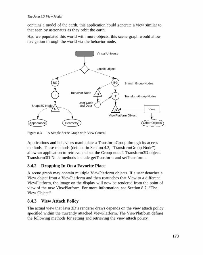
The Java 3D View Model
r to
w
s
ct.
s at of
olicyes
contains a model of the earth, this application could generate a view similathat seen by astronauts as they orbit the earth.
Had we populated this world with more objects, this scene graph would allonavigation through the world via the behavior node.
Figure 8-3 A Simple Scene Graph with View Control
Applications and behaviors manipulate a TransformGroup through its accesmethods. These methods (defined in Section 4.3, “TransformGroup Node”)allow an application to retrieve and set the Group node’s Transform3D objeTransform3D Node methods include getTransform and setTransform.
8.4.2 Dropping In On a Favorite Place
A scene graph may contain multiple ViewPlatform objects. If a user detacheView object from a ViewPlatform and then reattaches that View to a differenViewPlatform, the image on the display will now be rendered from the pointview of the new ViewPlatform. For more information, see Section 8.7, “TheView Object.”
8.4.3 View Attach Policy
The actual view that Java 3D’s renderer draws depends on the view attach pspecified within the currently attached ViewPlatform. The ViewPlatform definthe following methods for setting and retrieving the view attach policy.
BG
Virtual Universe
Locale Object
Branch Group Nodes
BBehavior NodeTT TransformGroup Nodes
SShape3D Node
Appearance Geometry
ViewPlatform Object
VP
User Codeand Data
BG
View
Other Objects
173

Java 3D API Specification—Version 1.0 August 1, 1997
174
y. as a
al
the
tnt is
tion
s that
ical
o
ble”
t by
Methods
public final void setViewAttachPolicy(int policy)public final int getViewAttachPolicy()
These methods set and retrieve the coexistence center in virtual world policThe view attach policy determines how Java 3D places the user’s eye pointfunction of head position. The variable can contain one of:NOMINAL_SCREEN, NOMINAL_SCREEN_SCALED, NOMINAL_HEAD,or NOMINAL_FEET.
A ViewPlatform’sView Attach Policy determines how Java 3D places the virtueyepoint within the ViewPlatform. The policy can have one of the followingvalues:
• NOMINAL_HEAD – Setting ViewAttachPolicy toNOMINAL_HEADensures thatthe end-user’s nominal eye-position in the physical world corresponds tovirtual eye’s nominal eye-position in the virtual world (the ViewPlatform’sorigin). In essence, this policy tells Java 3D to position the virtual eyepoinrelative to the ViewPlatform origin in the same way as the physical eyepoipositioned relative to its nominal physical-world origin. Deviations in thephysical eye’s position and orientation from nominal in the physical worldgenerate corresponding deviations of the virtual eye’s position and orientain the virtual world.
• NOMINAL_FEET – Setting ViewAttachPolicy toNOMINAL_FEET ensures thatthe end-user’s virtual feet always touch the virtual ground. This policy tellJava 3D to compute the physical to virtual world correspondence in a wayensures that Java 3D enforces this constraint. Java 3D does that byappropriately offsetting the physical eye’s position by the end-user’s physheight. Java 3D uses thenominalEyeHeightFromGround parameter found inthe PhysicalBody object (see Section 8.10, “The PhysicalBody Object”) tperform this computation.
• NOMINAL_SCREEN – Setting ViewAttachPolicy toNOMINAL_SCREEN allowsan application to always have the virtual eyepoint appear at some “viewadistance from a point-of-interest. This policy tells Java 3D to compute thephysical-to-virtual-world correspondence in a way that ensures that therenderer moves the nominal virtual-eyepoint away from the point of interesthe amount specified by thenominalEyeDistanceFromNominalScreen
parameter found in the PhysicalBody object (see Section 8.10, “ThePhysicalBody Object”). This is the default mode.
• NOMINAL_SCREEN_SCALED – Setting ViewAttachPolicy toNOMINAL_SCREEN_SCALED specifies that Java 3D should locate the user’svirtual head at a point offset bynominalEyeDistanceFromNominalScreen
The Java 3D View Model
n).m an
is in a
D
roupeeould
(if a
g on
ribesd
alionrerction
from the user’s physical head (as determined by the current head positioThis offset, in effect, creates a viewpoint where the user sees an object frooptimal viewpoint. Additionally, the view platform to physical coexistancetransform is scaled by a value specified in the view. By default, this scalederived from the screen size. This allows an application to define a worldnormalized [–1,1] space and view it on a screen of any size.
8.4.4 Associating Geometry With a ViewPlatform
Java 3D does not have any built-in semantics for displaying a visiblemanifestation of a ViewPlatform within the virtual world (anavatar). However,a developer can construct and manipulate an avatar using standard Java 3constructs.
A developer can construct a small scene graph consisting of a TransformGnode, a behavior leaf node, and a shape node and insert it directly under thBranchGroup node associated with the ViewPlatform object. The shape nodwould contain a geometric model of the avatar’s head. The behavior node wchange the TransformGroup’s transform periodically to the value stored in aView object’sUserHeadToVworld parameter, (see Section C.5, “The ViewObject”). The avatar’s virtual head, represented by the shape node, will nowmove around in lock-step with the ViewPlatform’s TransformGroup andanyrelative position and orientation changes of the user’s actual physical head system has a head tracker).
8.5 Generating a ViewJava 3D generates viewing matrices in one of a few different ways, dependinwhether the end-user has a head-mounted or a room-mounted displayenvironment and whether or not head tracking is enabled. This section descthe computation for a non-head-tracked, room-mounted display—a standarcomputer display. Other environments are described in Appendix C, “ViewModel Implementation Details.”
In the absence of head-tracking, the ViewPlatform’s origin specifies the virtueye’s location and orientation within the virtual world. However, the eye locatprovides only part of the information needed to render an image. The rendealso needs a projection matrix. In the default mode, Java 3D uses the projepolicy, the specified field-of-view information and the front and back clipdistances to construct a viewing frustum.
175
Java 3D API Specification—Version 1.0 August 1, 1997
176
a 3Dontedey
t
’s
not
del
themleform of
w’s
ystemtemour
-user
8.5.1 Composing Model and Viewing Transformations
Figure 8-4 shows a simple scene graph. To draw the object labeled “S,” Javinternally constructs the appropriate model, view platform, eye, and projectimatrices. Conceptually, the model transform for a particular object is compuby concatenating all the matrices in a direct path between the object and thVirtualUniverse. The view matrix is then computed—again, conceptually—bconcatenating all the matrices between the VirtualUniverse object and theViewPlatform attached to the current View object. The eye and projectionmatrices are constructed from the View object and its associated componenobjects.
In our scene graph, what we would normally consider the model transformwould consist of the three transforms: LT1T2. By multiplying LT1T2 by a vertexin the shape object, we would transform that vertex into the VirtualUniversecoordinate system. What we would normally consider the view platformtransform would be (LTv1)–1 or Tv1
–1L–1. This presents a problem sincecoordinates in the virtual universe are 256-bit fixed point values, which canbe used to efficiently represent transformed points.
Fortunately, however, there is a solution to this problem. Composing the moand view platform transforms gives us Tv1
–1L–1LT1T2 = Tv1–1IT1T2 = Tv1
–1T1T2, thematrix that takes vertices in an object’s local coordinate system and places in the ViewPlatform’s coordinate system. Note that the high-resolution Locatransforms cancel each other out which removes the need to actually transpoints into high-resolution VirtualUniverse coordinates. The general formulathe matrix that transforms object coordinates to ViewPlatform coordinates isTvn
–1...Tv2–1Tv1
–1T1T2...Tm.
As was mentioned above, the View object contains the remainder of the vieinformation, specifically the eye matrix E that takes points in the ViewPlatformlocal coordinate system and translates them into the user’s eye coordinate sand the projection matrix P that projects objects in the eye’s coordinate sysinto clipping coordinates. The final concatenation of matrices for rendering shape object “S” on the specified Canvas3D is PETv1
–1T1T2. In general this isPETvn
–1...Tv2–1Tv1
–1T1T2...Tm.
The details of how Java 3D constructs the matrices E and P in different endconfigurations is described in Appendix C, “View Model ImplementationDetails.”

The Java 3D View Model
calesate
dles
ed tothe
ormerse
is
Figure 8-4 Object and ViewPlatform Transformations
8.5.2 Multiple Locales
Java 3D supports multiple high-resolution Locales. In some cases, these Loare close enough to each other that they can “see” each other, meaning thobjects can be rendered even though they are not in the same Locale as thViewPlatform object that is attached to the View. Java 3D automatically hanthis case without the application having to do anything. As in the previousexample, where the ViewPlatform and the object being rendered are attachthe same Locale, Java 3D internally constructs the appropriate matrices in case where the ViewPlatform and the object being rendered arenot attached tothe same Locale.
Let’s take two Locales, L1 and L2, with the View attached to a ViewPlatform inL1. If we remember our general formula, the modeling transform—the transfthat takes points in object coordinates and transforms them into VirtualUnivcoordinates—is: LT1T2...Tm. In our specific example, a point in Locale L2 wouldbe transformed into VirtualUniverse coordinates by: L2T1T2...Tm. The viewplatform transform would be (L1Tv1Tv1...Tvn)–1 or Tvn
–1...Tv2–1Tv1
–1L1–1. Composing
these two matrices gives us Tvn–1...Tv2
–1Tv1–1L1
–1L2T1T2...Tm. Thus, to renderobjects in another Locale, it is sufficient to compute L1
–1L2 and use that as thestarting matrix when composing the model transforms. Given that a Locale represented by a single high-resolution coordinate position, the transform L1
–1L2
BG
VP
Virtual Universe
Hi-Res Locale
View Canvas3D Screen3D
PhysicalBody
PhysicalEnvironment
T1
T2
S
Tv1
L
177

Java 3D API Specification—Version 1.0 August 1, 1997
178
igh-niteing
can
s allrmine. Itiew.
w
is a simple translation by L2 – L1. Again, it is not necessary to actually transformpoints into high-resolution VirtualUniverse coordinates.
In general, Locales that are close enough such that the difference in their hresolution coordinates can be represented in double precision by a non-infivalue are close enough to be rendered. In practice, more sophisticated culltechniques can be used to only render those Locales that really are “closeenough.”
8.6 A Minimal EnvironmentAn application must create a minimal set of Java 3D objects before Java 3Drender to a display device. In addition to a Canvas3D object, the applicationmust create a View object, with its associated PhysicalBody andPhysicalEnvironment objects, and the following scene graph elements:
• A VirtualUniverse object
• A High-resolution Locale object
• A BranchGroup node object
• A TransformGroup node object with associated transform
• A ViewPlatform leaf node object that defines the position and orientationwithin the virtual universe for generating views
8.7 The View ObjectThe View object coordinates all aspects of the rendering process. It containthe parameters or references to objects containing the parameters that detehow to render images to the windows represented by its Canvas3D objectsalso contains the set of canvases that represent various “windows” onto a v
Java 3D allows applications to specify multiple simultaneously-active Viewobjects, each controlling its own set of canvases. For more details on a Vieobject’s internals, see Section C.5, “The View Object.”
Constructors
The View object specifies the following constructor.
public View()
Constructs and initializes a new View object.
Methods
The View object specifies the following methods.

The Java 3D View Model
ee
is
—the
e,”
bjectithinion
entsee
public final void setPhysicalBody(PhysicalBody physicalBody)public final PhysicalBody getPhysicalBody()
These methods set and retrieve the View’s PhysicalBody object. SeeSection 8.10, “The PhysicalBody Object,” for more information on thePhysicalBody object.
public final void setPhysicalEnvironment(PhysicalEnvironmentphysicalEnvironment)
public final PhysicalEnvironment getPhysicalEnvironment()
These methods set and retrieve the View’s PhysicalEnvironment object. SeSection 8.11, “The PhysicalEnvironment Object,” for more information on thPhysicalEnvironment object.
public final void attachViewPlatform(ViewPlatform vp)
This method attaches a ViewPlatform leaf node to this View, replacing theexisting ViewPlatform. If the ViewPlatform is part of a live scene graph, or issubsequently made live, the scene graph is rendered into all canvases in thView object’s list of Canvas3D objects. To remove a ViewPlatform withoutattaching a new one—causing the View to no longer be rendered—a nullreference may be passed to this method. In this case, the behavior is as ifrendering were simultaneously stopped on all canvases attached to the viewlast frame that was rendered in each remains visible until the View is againattached to a live ViewPlatform object. See Section 5.10, “ViewPlatform Nodfor more information on ViewPlatform objects.
public final ViewPlatform getViewPlatform()
This method retrieves the currently attached ViewPlatform object.
public final Canvas3D getCanvas3D(int index)public final void setCanvas3D(Canvas3D canvas3D, int index)public final void addCanvas3D(Canvas3D canvas3D)public final void insertCanvas3D(Canvas3D canvas3D, int index)public final void removeCanvas3D(int index)public final void removeCanvas3D(Canvas3D canvas3D)
These methods set, retrieve, add to, insert after, and remove a Canvas3D ofrom this View. The index specifies the reference to the Canvas3D object wthe View object. See Section 8.9, “The Canvas3D Object” for more informaton Canvas3D objects.
public final Enumeration getAllCanvas3Ds()
This method gets the enumeration object of all the canvas3Ds.
public final void addInputDevice(InputDevice device)public final Enumeration allInputDevices()
These methods allow introducing new input devices into a Java 3D environmand retrieving all the input devices available within a Java 3D environment, Section 9.1, “InputDevice Interface” for more information on InputDevices.
179

Java 3D API Specification—Version 1.0 August 1, 1997
180
ent(sees).
w.
et tohed
dow
e
icy
orld.
public final void addAudioDevice(AudioDevice device)public final Enumeration allAudioDevices()
These methods allow introducing new audio devices into a Java 3D environmand retrieving all the audio devices available within a Java 3D environment Section 11.1, “AudioDevice Interface,” for more information on AudioDevice
8.7.1 Projection Policy
The projection policy informs Java 3D whether it should generate a parallelprojection or a perspective projection. This policy is attached to the Java 3DView object.
Methods
public final void setProjectionPolicy(int policy)public final int getProjectionPolicy()
These two methods set and retrieve the current projection policy for this vieThe projection policy is as follows:
• PARALLEL_PROJECTION specifies that Java 3D should compute aparallel projection.
• PERSPECTIVE_PROJECTION specifies that Java 3D should compute aperspective projection. This is the default setting.
public final void setLocalEyeLightingEnable(boolean flag)public final boolean getLocalEyeLightingEnable()
These methods set and retrieve the local eye lighting flag, which indicateswhether the local eye point is used in lighting calculations for perspectiveprojections. If this flag is set to true, the view vector is calculated per-vertexbased on the direction from the actual eye point to the vertex. If this flag is sfalse, a single view vector is computed from the eye point to the center of tview frustum. This is called infinite eye lighting. Local eye lighting is disableby default, and is ignored for parallel projections.
8.7.1.1 Window Sizing and Movement
When users resize or move windows, Java 3D can choose to think of the winas attached either to the physical world or to the virtual world. The windowresize policy allows an application to specify how the view model will handlresize requests. The window resize policies are specified by two constants.
Constants
public static final int PHYSICAL_WORLD
This variable specifies the policy for resizing and moving windows. This polis used in specifying windowResizePolicy and windowMovementPolicy. Thisvariable specifies that the specified action takes place only in the physical w

The Java 3D View Model
ual
aedg
w
n thelargere is
onwithinoal
va 3Dom
eyinge
public static final int VIRTUAL_WORLD
This variable specifies that Java 3D applies the associated policy in the virtworld.
Methods
public final void setWindowResizePolicy(int policy)public final int getWindowResizePolicy()
This variable specifies how Java 3D modifies the view when a user resizeswindow. A value ofPHYSICAL_WORLD states that Java 3D will treat window resizoperations asonly happening in the physical world. This implies that rendereobjects continue to fill the same percentage of the newly sized window, usinmore or less pixels to draw those objects, depending on whether the windogrew or shrank in size. A value ofVIRTUAL_WORLD states that Java 3D will treatwindow resize operations as also happening in the virtual world whenever aresize occurs in the physical world. This implies that rendered objects remaisame size (use the same number of pixels), but since the window becomes or smaller, the user sees more or less of the virtual world. The default valuPHYSICAL_WORLD.
public final void setWindowMovementPolicy(int policy)public final int getWindowMovementPolicy()
This variable specifies what part of the virtual world Java 3D will draw as afunction of the window location on the display screen. A value ofPHYSICAL_WORLD states that the window acts as if it movesonly on the physicalscreen. As the user moves the window on the screen, the window’s positionthe screen changes but Java 3D continues to draw exactly the same image that window. A value ofVIRTUAL_WORLD states that the window acts as if it alsmoves within the virtual world. As the user moves the window on the physicscreen, the window’s position on the screen changes and the image that Jadraws changes as well to match what would be visible in the virtual world fra window in that new position. The default value isPHYSICAL_WORLD.
8.7.2 Clip Policies
The clip policies determine how Java 3D interprets clip distances to both thnear and far clip planes. The policies can contain one of four values specifwhether a distance measurement should be interpreted in the physical or thvirtual world and whether that distance measurement should be interpretedrelative to the physical eyepoint or the physical screen.
181

Java 3D API Specification—Version 1.0 August 1, 1997
182
ne.
ne.
een
en
and
l is
ront.wn.
Methods
public final void setFrontClipPolicy(int policy)public final int getFrontClipPolicy()public final void setBackClipPolicy(int policy)public final int getBackClipPolicy()
The front clip policy determines where Java 3D places the front clipping-plaValues are one of:PHYSICAL_EYE, PHYSICAL_SCREEN, VIRTUAL_EYE, orVIRTUAL_SCREEN. The default value isPHYSICAL_EYE.
Theback clip policy determines where Java 3D places the back clipping-plaValues are one of:PHYSICAL_EYE, PHYSICAL_SCREEN, VIRTUAL_EYE, orVIRTUAL_SCREEN. The default value isPHYSICAL_EYE.
These policies are defined as follows.
• PHYSICAL_EYE specifies that the plane is located relative to the eye’sposition as measured in the physical space (in meters). Note that this isdifferent from eye coordinates.
• PHYSICAL_SCREEN specifies that the plane is located relative to the scr(i.e., the image plate) as measured in physical space (in meters).
• VIRTUAL_EYE specifies that the plane is located relative to the virtualeyepoint as measured in virtual world coordinates.
• VIRTUAL_SCREEN specifies that the plane is located relative to the scre(i.e., the image plate) as measured in virtual world coordinates.
8.7.3 Projection and Clip Parameters
The projection and clip parameters determine the view model’s field of view the front and back clip distances.
public final void setFieldOfView(double fieldOfView)public final double getFieldOfView()
In the default non-head-tracked mode, this value specifies the view model’shorizontal field-of-view in radians. This value is ignored when the view modeoperating in head-tracked mode, or when the Canvas3D’s window eyepointpolicy is set to a value other than the default setting ofRELATIVE_TO_FIELD_OF_VIEW (see Section C.5.3, “Window Eyepoint Policy”).
public void setFrontClipDistance(double distance)public double getFrontClipDistance()
This value specifies the distance away from the clip-origin, specified by the fclip policy variable, in the direction of gaze where objects stop disappearingObjects closer than the clip-origin offset by the front-clip distance are not dra

The Java 3D View Model
by
ackg.
notd by
ce is.5,
ed. ItMT. is
to this starttiplethef a.
ing is
foredled
Measurements are done in the space—physical or virtual—that is specifiedthe associated front clip policy parameter.
public void setBackClipDistance(double distance)public double getBackClipDistance()
This value specifies the distance away from the clip-origin (specified by the bclip policy variable) in the direction of gaze where objects begin disappearinObjects farther away from the clip-origin offset by the back-clip distance aredrawn. Measurements are done in the space (physical or virtual) as specifiethe associated back clip policy parameter. The View object’s back clip distanignored if the scene graph contains an active Clip leaf node (see Section 5“Clip Node”).
8.7.4 Frame Start Time and Durationpublic long getCurrentFrameStartTime()
This method returns the time at which the most recent rendering frame startis defined as the number of milliseconds since January 1, 1970 00:00:00 GSince multiple canvases might be attached to this View, the start of a framedefined as the point just prior to clearing any canvas attached to this view.
public long getLastFrameDuration()
This method returns the duration, in milliseconds, of the most recentlycompleted rendering frame. The time taken to render all canvases attached view is measured. This duration is computed as the difference between theof the most recently-completed frame and the end of that frame. Since mulcanvases might be attached to this View, the start of a frame is defined as point just prior to clearing any canvas attached to this view, while the end oframe is defined as the point just after swapping the buffer for all canvases
8.7.5 Scene Antialiasingpublic final void setSceneAntialiasingEnable(boolean flag)public final boolean getSceneAntialiasingEnable()
These methods set and retrieve the scene antialiasing flag. Scene antialiaseither enabled or disabled for this view. If enabled, the entire scene will beantialiased on each canvas in which scene antialiasing is available. Sceneantialiasing is disabled by default.
8.7.6 Depth Bufferpublic final void setDepthBufferFreezeTransparent(boolean flag)public final boolean getDepthBufferFreezeTransparent()
The set method enables or disables automatic freezing of the depth buffer objects rendered during the transparent rendering pass (i.e., objects renderusing alpha blending) for this view. If enabled, depth buffer writes are disab
183

Java 3D API Specification—Version 1.0 August 1, 1997
184
bufferis
e
e
tem.the x
jectas by
ingers.
s.
ht in
n,s
during the transparent rendering pass regardless of the value of the depth write enable flag in the RenderingAttributes object for a particular node. Thflag is enabled by default. The get method retrieves this flag.
8.8 The Screen3D ObjectThe Screen3D object provides a 3D version of the AWT screen object. Itcontains the screen’s physical properties. Java 3D will support multiple activScreen3D objects as soon as AWT support is available. Of course, multiplescreens are only available if the machine configuration has multiple outputscreens. Java 3D needs to primarily know the physical size (in meters) of thScreen3D’s visible, addressable raster (theimage plate) and, in head-trackingmode, the position and orientation of this raster relative to a well-definedphysical world coordinate system, specifically the trackerbase coordinate sysJava 3D also needs to know how many pixels the raster can display in both and y dimensions. This information allows Java 3D to calculate a pixel’sphysical dimension.
Calibration utilities can change a Screen3D’s physical characteristics orcalibration transforms, see Section C.6, “The Screen3D Object.”
The Screen3D object has no public constructors. Instead, the Screen3D obassociated with a particular Canvas3D object can be obtained from the canvcalling thegetScreen3D method. See Section 8.9.2, “Other Canvas3DParameters.”
Methods
These methods provide applications with information concerning the underlydisplay hardware, such as the screen’s width and height in pixels or in met
public Dimension getSize()
This method retrieves the screen’s (image plate’s) width and height in pixel
public final double getPhysicalScreenWidth()public final double getPhysicalScreenHeight()
These methods retrieve the screen’s (image plate’s) physical width and heigmeters.
8.9 The Canvas3D ObjectThe Canvas3D object extends the AWT Canvas object to include 3D-relatedinformation such as the size of the Canvas in pixels, the Canvas3D’s locatioalso in pixels, within a Screen3D object, and whether or not the Canvas ha

The Java 3D View Model
een3Dunits,ters.
al
t.
on
s3D’s
ntial
sthe
s
stereo enabled. Because all Canvas3D objects contain a reference to a Scrobject and because Screen3D objects define the size of a pixel in physical Java 3D can convert a Canvas3D size in pixels to a physical world size in meIt can also determine the Canvas3D’s position and orientation in the physicworld.
Constructors
The Canvas3D object specifies one constructor.
public Canvas3D(GraphicsConfiguration graphicsConfiguration)
This constructs and initializes a new Canvas3D object given a validGraphicsConfiguration object. Java 3D can render into this Canvas3D objec
For more information on the GraphicsConfiguration object see the Java 2Dspecification, which will be part of AWT in JDK 1.2
8.9.1 Window System Provided Parameters
Java 3D specifies the size of a Canvas3D in pixels. It extracts this informatidirectly from the AWT’s window system. Java 3D only allows applications toaccess these values, not change them.
public Dimension getLocationOnScreen()public Dimension getSize()
These methods, inherited from the parent Canvas class, retrieve the Canvascreen position and size in pixels.
8.9.2 Other Canvas3D Parameterspublic final boolean getStereoAvailable()
This method specifies whether the underlying hardware supports field-sequestereo on this canvas.
public final boolean getStereoEnable()public final void setStereoEnable(boolean flag)
These methods set or retrieve the flag indicating whether this Canvas3D hastereo enabled. If enabled, Java 3D generates left and right eye images. If Canvas3D’s StereoAvailable flag is false, Java 3D displays only theleft eye’sview even if an application sets StereoEnable to true. This parameter allowapplications to enable or disable stereo on a canvas-by-canvas basis.
public final void getDoubleBufferAvailable()
This method specifies whether the underlying hardware supports doublebuffering on this canvas.
185

Java 3D API Specification—Version 1.0 August 1, 1997
186
sog
el
theers tod theils.ead-
d in
n in
public final boolean getDoubleBufferEnable()public final void setDoubleBufferEnable(boolean flag)
These methods set or retrieve the flag indicating whether this Canvas3D hadouble buffering enabled. If disabled, all drawing is to the front buffer and nbuffer swap will be done between frames. It should be stressed that runninJava 3D with double buffering disabled is not recommended.
public final boolean getSceneAntialiasingAvailable()
This method specifies whether the underlying hardware supports scene levantialaising.
public final View getView()
Retrieves the view object that points to this Canvas3D.
public final Screen3D getScreen3D()
Retrieves the Screen3D object that this Canvas3D is attached to.
public void processEvent(AWTEvent evt)
This method overrides the AWT’s handleEvent class.
public void paint(Graphics g)
This method overrides the AWT’s paint class.
8.10 The PhysicalBody ObjectJava 3D defines a PhysicalBody object that contains information concerningend-user’s body physical characteristics. The head parameters allow end-usspecify their own head’s characteristics, such as the location of the eyes aninterpupilary distance. See Section C.8, “The PhysicalBody Object,” for detaThe default values are sufficient for applications that are running in a non-htracked environment and that do not manually set the eye-point.
Constructors
public PhysicalBody()
This constructor constructs and initializes a default PhysicalBody object.
8.11 The PhysicalEnvironment ObjectThe PhysicalEnvironment object defines several methods that are describeSection C.9, “The PhysicalEnvironment Object.” The default values aresufficient for applications that do not use continuous input devices that are rua non-head-tracked display environment.

The Java 3D View Model
Constructors
public PhysicalEnvironment()
Constructs and initializes a default PhysicalEnvironment object.
187

Java 3D API Specification—Version 1.0 August 1, 1997
188

C H A P T E R 9
I for
d
d
lueswith
ains
r cannsut
icese-
r
e-to-
serve
Input Devices
JAVA 3D provides access to keyboards and mice using Java’s standard APkeyboard and mouse support. Additionally, it provides access to a variety ofcontinuous input devices such as six-degree-of-freedom (6DOF) trackers anjoysticks.
Continuous input devices like 6DOF trackers and joysticks have well definecontinuous inputs. Trackers produce a position and orientation that Java 3Dstores internally as a transform matrix. Joysticks produce two continuous vain the range (-1.0, 1.0) that Java 3D stores internally as a transform matrix an identity rotation (no rotation) and one of the Joystick values as the xtranslation and the other as the y translation component.
Unfortunately, continuous input devices do not have the same level ofconsistency when it comes to their associated switches or buttons. Still thenumber of buttons or switches attached to a particular sensing element remconstant across all sensing elements associated with a single device.
9.1 InputDevice InterfaceThe InputDevice interface specifies an abstract input device that a developeuse in implementing a device driver for a particular device. All implementatioof an InputDevice interface must implement all of its methods. Java 3D’s inpdevice scheduler uses these methods to interact with specific devices andincorporates their input. In addition to the generic methods that all InputDevmust provide, implementations of an InputDevice will contain whatever devicspecific information and methods necessary to maintain that device’s propefunctioning.
All input devices consist of a number of Sensor objects that have a direct onone relationship with that device’s physical detectors. Sensor objects servedouble duty. They not only represent actual physical detectors but they also
189

Java 3D API Specification—Version 1.0 August 1, 1997
190
n can
n,ver
lse
ice.
sthe
alues
as abstract six-degree-of-freedom transformations that a Java 3D applicatioaccess. The Sensor class is described in more detail in the next section.
9.1.1 The Abstract Interface
All input devices implement a consistent interface that allows the initializatioprocessing of input, and finalization of a particular input device. A device-driprogrammer would implement the following methods in whatever device-specific manner is necessary to perform the specified operations.
Constants
public static final int POLLEDpublic static final int STREAMING
These flags specify whether the associated device works in polled mode orstreaming mode.
Methods
public abstract boolean initialize()
This method initializes the device. It returns true if initialization succeeded, faotherwise.
public abstract void setProcessingMode(int mode)public abstract int getProcessingMode()
These methods set and retrieve this device’s processing mode.
public abstract int getSensorCount()
This method returns the number of Sensor objects associated with this dev
public abstract Sensor getSensor(int sensorIndex)
This method returns the specified Sensor associated with this device.
public abstract void setNominalPositionAndOrientation()
This method sets the device’s current position and orientation as the devicenominal position and orientation (establishes its reference frame relative to “Tracker base” reference frame). This method is most useful in defining anominal pose in immersive head-tracked situations.
public abstract void pollAndProcessInput()
This method first polls the device for data values and then processes the vreceived from the device.
public abstract void processStreamInput()
This method processes the device’s streaming input.
public abstract void close()
This method closes the device.

Input Devices
ificble
r-
jectce
the in
nceptnd the. Anate
from6DOF
ernsors.raph
e
d
9.1.2 Instantiating and Registering A New Device
A browser or applications developer must instantiate whatever system specinput devices that he or she needs and that exist on the system. This availadevice information typically exists in a site configuration file. The browser oapplication will instantiate the viewing environment as requested by the enduser.
The API for instantiating devices is site specific, but it consists of a device obwith a constructor and at least all of the methods specified in the InputDeviinterface.
Once instantiated, the browser or application must register the device with Java 3D input device scheduler. The API for registering devices is specifiedSection 8.7, “The View Object.” TheaddInputDevice method introduces newdevices to the Java 3D environment and theallInputDevices method producesan enumeration that allows examining all available devices within a Java 3Denvironment.
9.2 SensorsThe Java 3D API provides only an abstract concept of a device. Rather itabstracts away issues of devices and device models, defining instead the coof a sensor. A sensor consists of a time-stamped sequence of input values astate of the buttons or switches at the time that Java 3D sampled the valueSensor also contains a hotspot offset specified in that sensor’s local coordisystem. If not specified, the hotspot is (0.0, 0.0, 0.0).
Since a typical hardware environment contains multiple sensing elements,Java 3D maintains an array of sensors. Users can access a sensor directlytheir Java code or they can assign a sensor to one of Java 3D’s predefined entities such as the UserHead.
9.2.1 Using and Assigning Sensors
Using a sensor is as easy as accessing an object. The application developwrites Java code to extract the associated sensor value from the array of seThe developer can then directly apply that value to an element in a scene gor process the sensor values in whatever way necessary.
Java 3D includes three special six-degree-of-freedom (6DOF) entities. Thesinclude UserHead, DominantHand, and NondominantHand. An applicationdeveloper can assign or change which sensor drives one of these predefine6DOFs. Java 3D uses the specified sensor to drive the 6DOF entity—most
191

Java 3D API Specification—Version 1.0 August 1, 1997
192
. At ationayation
en a
nsorateds.
th the
e no
t the
ucted,
visibly the View. Application developers should use this facility carefully. It isquite easy to get the effect of a WristCam—very disconcerting as well.
9.2.2 Behind the (Sensor) Scenes
Java 3D does not provide raw tracker or joystick-generated data in a sensorminimum, Java 3D normalizes the raw data using the registration and calibraparameters either provided by or provided for the end user. It additionally mfilter and process the data to remove noise and improve latency. The applicprogrammer can suppress this latter effect on a sensor-by-sensor basis.
Unfortunately, tracker or sensor hardware may not always be available or boperational. Thus, Java 3D provides both an available and an enable flag oper-sensor basis.
9.2.3 The Sensor Object
Java 3D stores its sensor array in the PhysicalEnvironment object. Each Sein the array consists of a fixed number of SensorRead objects. Also associwith each SensorRead is its timestamp and the state of that sensor’s button
Constants
The Sensor object specifies the following constants.
public static final int PREDICT_NONEpublic static final int PREDICT_NEXT_FRAME_TIME
These flags define the Sensor’s predictor type. The first flag defines noprediction. The second flag specifies to generate the value to correspond winext frame time.
public static final int NO_PREDICTORpublic static final int HEAD_PREDICTORpublic static final int HAND_PREDICTOR
These flags define the Sensor’s predictor policy. The first flag specifies to usprediction policy. The second flag specifies to assume that the sensor ispredicting head position or orientation. The third flag specifies to assume thasensor is predicting hand position or orientation.
public static final int DEFAULT_SENSOR_READ_COUNT
These constant specifies the default number of SensorRead objects constrwhen no SensorRead count is specifies.
Constructors
The Sensor object specifies the following constructors.

Input Devices
d
n theo.
df
ocal
thisber of
e
ns
public Sensor(InputDevice device)public Sensor(InputDevice device, int sensorReadCount)public Sensor(InputDevice device, int sensorReadCount,
int sensorButtonCount)
These methods construct a new Sensor object associated with the specifiedevice and consisting of either a either default number of SensorReads orsensorReadCount SensorReads and a hot spot at (0.0, 0.0, 0.0) specified iSensor’s local coordinate system. The default for sensorButtonCount is zer
public Sensor(InputDevice device, Point3d hotspot)public Sensor(InputDevice device, int sensorReadCount,
Point3d hotspot)public Sensor(InputDevice device, int sensorReadCount,
int sensorButtonCount, Point3d hotspot)
These methods construct a new Sensor object associated with the specifiedevice and consisting ofsensorReadCount SensorReads or a default number oSensorReads and an offset defining the Sensor’s hot spot in the Sensor’s lcoordinate system. The default for sensorButtonCount is zero.
Methods
public int getSensorReadCount()public int getSensorButtonCount()
These methods retrieve the number of SensorRead objects associated withsensor and the number of buttons associated with this sensor. Both the numSensor Read objects and the number of buttons are determined at Sensorconstruction time.
public void getHotspot(Point3d hotspot)public void setHotspot(Point3d hotspot)
These methods set and retrieve the sensor’s hotspot offset. The hotspot isspecified in the Sensor’s local coordinate system.
public void lastRead(Transform3D read)public void lastRead(Transform3D read, int k)
These methods extract the most recent sensor reading and thekth most recentsensor reading from the sensor object. In both cases, the methods copy thsensor value into the specified argument.
public void getRead(Transform3D read)public void getRead(Transform3D read, long deltaT)
The first method computes the sensor reading consistent with the predictiopolicy and copies that value into theread matrix. The second method computethe sensor reading consistent as of timedeltaT in the future and copies thatvalue into theread matrix. All times are in milliseconds.
193
Java 3D API Specification—Version 1.0 August 1, 1997
194
ding
ent
pe is
dingray.
gle
public long lastTime()public long lastTime(int k)
These methods return the time associated with the most-recent sensor reaand with thekth most-recent sensor reading, respectively.
public int[] lastButtons()public int[] lastButtons(int k)
These methods return the state of the buttons associated with the most-recsensor reading and thekth most-recent sensor reading, respectively.
public void setPredictor(int predictor)public int getPredictor()
These methods set and retrieve the Sensor’s predictor type. The predictor tyone of: NO_PREDICTOR, HEAD_PREDICTOR, or HAND_PREDICTOR.
public void setPredictionPolicy(int policy)public int getPredictionPolicy()
These methods set and retrieve the Sensor’s predictor policy. The predictorpolicy is one of: PREDICT_NONE, PREDICT_NEXT_FRAME_TIME.
public void setDevice(InputDevice device)public InputDevice getDevice()
These methods set and retrieve the Sensor’s input device.
public SensorRead getCurrentSensorRead()
This method returns the current number of sensor read objects per sensor.
public void setNextSensorRead(long time, Transform3D transform,int buttons[])
This method sets the next sensor read objects to the specified values, incluthe next SensorRead’s associated time, transformation, and button state ar
9.2.4 The SensorRead Object
A SensorRead object encapsulates all the information associated with a sinreading of a sensor.
Constructors
The SensorRead object specifies the following constructor.
public SensorRead())
Creates a new SensorRead object.

Input Devices
e toa
tof that
ice to and a
Methods
public final void set(Transform3D t1)public final void get(Transform3D result)
These methods set and retrieve the read’s transform3D. They allow a devicstore a new rotation and orientation value into the SensorRead object and consumer of that value to access it.
public final void setTime(long time)public final long getTime()
These methods set and retrieve the read’s timestamp. They allow a device store a new timestamp value into the SensorRead object and a consumer ovalue to access it.
public final void setButtons(int values)public final int getButtons(int values)
These methods set and retrieve the read’s button values. They allow a devstore an integer that encodes the button values into the SensorRead objectconsumer of those values to access the state of the buttons.
195

Java 3D API Specification—Version 1.0 August 1, 1997
196

C H A P T E R 10
dssingvior’s3D
Forivelyate.
anaiory its
e
Behaviors, Interpolators, anPicking
BEHAVIOR nodes provide the means for animating objects, processingkeyboard and mouse inputs, reacting to movement, and enabling and procepick events. Behavior nodes contain Java code and state variables. A BehaJava code can interact with Java objects, change node values within a Javascene graph, change the behavior’s internal state; in general perform anycomputation it wishes.
Simple behaviors can add surprisingly interesting effects to a scene graph. example, one can animate a rigid object by using a behavior node to repetitmodify the TransformGroup node that points to the object one wish to animAlternatively, a behavior node can track the current position of a mouse andmodify portions of the scene graph in response.
10.1 Behavior ObjectA Behavior leaf node object contains a scheduling region and two methods:initialization method called once when the behavior becomes “live” and processStimulus method called whenever appropriate by the Java 3D behavscheduler. The behavior object also contains the state information needed binitilization andprocessStimulus methods.
Thescheduling region defines a spatial volume that serves to enable thescheduling of Behavior nodes. A Behavior node isactive (can receive stimuli)whenever a ViewPlatform’s activation volume intersects a Behavior object’sscheduling region. Only active behaviors can receive stimuli.
The initialization method allows a behavior object to initialize its internal statand specify its initial wakeup condition(s). Java 3D invokes a behavior’s
197

Java 3D API Specification—Version 1.0 August 1, 1997
198
d toew
ott be
a aresusetion,
es.ns.viory the
cene
to theess
lwaysc
ration
.
er).
initialization code when the behavior’s containing BranchGroup node is addethe virtual universe. Java 3D does not invoke the initialization method in a nthread. Thus, for Java 3D to regain control, the initialization method must nexecute an infinite loop. It must return. Furthermore, a wakeup condition musset or else the behavior’sprocessStimulus method is never executed.
TheprocessStimulus method receives and processes a behaviors’ ongoingmessages. The Java 3D behavior scheduler invokes a behavior node’sprocessStimulus method when a ViewPlatform’s activation volume intersectsbehavior object’s scheduling region and all of that behavior’s wakeup criteriasatisfied. TheprocessStimulus method performs its computations and action(possibly including the registration of state change information that could caJava 3D to wake other behavior objects), establishes its next wakeup condiand finally exits.
10.1.1 Code Structure
When the Java 3D behavior scheduler invokes a Behavior object’sprocessStimulus method, that method may perform any computation it wishUsually, it will change its internal state and specify its new wakeup conditioMost probably, it will manipulate scene graph elements. However, the behacode can only change those aspects of a scene graph element permitted bcapabilities associated with that scene graph element. A scene graph’scapabilities restrict behavioral manipulation to those manipulations explicitlyallowed.
The application must provide the Behavior object with references to those sgraph elements that the Behavior object will manipulate. The applicationprovides those references when it creates the Behavior object as argumentsbehavior’s constructor. Alternatively, the Behavior object itself can obtain accto the relevant scene graph elements either when Java 3D invokes itsinitialization behavior or each time Java 3D invokes its processStimulusbehavior.
Behavior methods have a very rigid structure. Java 3D assumes that they arun to completion (if needed, they can spawn threads). Each method’s basistructure consists of:
• Code to decode and extract references from the WakeupCondition enumethat caused the object’s awakening.
• Code to perform the manipulations associated with the WakeupCondition
• Code to establish this behavior’s new WakeupCondition.
• A path to Exit (so that execution returns to the Java 3D behavior schedul

Behaviors, Interpolators, and Picking
ent
o the
e in
t and
t and
ther
riatets
10.1.2 WakeupCondition Object
A WakeupCondition object is an abstract class specialized to fourteen differWakeupCriterion objects and to four combining objects containing multipleWakeupCriterion objects.
A Behavior node provides the Java 3D behavior scheduler with aWakeupCondition object. When that object’s WakeupCondition has beensatisfied, the behavior scheduler hands that same WakeupCondition back tBehavior via an enumeration.
10.1.3 WakeupCriterion Object
Java 3D provides a rich set of wakeup criteria that Behavior objects can usspecifying a complex WakeupCondition. These wakeup criterion can causeJava 3D’s behavior scheduler to invoke a behavior’sprocessStimulus methodwhenever:
• The center of a ViewPlatform enters a specified region
• The center of a ViewPlatform exits a specified region
• A behavior is activated
• A behavior is deactivated
• A specified TransformGroup node’s transform changes
• Collision is detected between a specified Shape3D node’s Geometry objecand any other object
• Movement occurs between a specified Shape3D node’s Geometry objecany other object it collides with
• A specified Shape3D node’s Geometry object no longer collides with any oobject
• A specified Behavior object posts a specific event
• A specified AWT event occurs
• A specified time interval elapses
• A specified number of frames have been drawn
• The center of a specified Sensor enters a specified region
• The center of a specified Sensor exits a specified region
A Behavior object constructs a WakeupCriterion by constructing the appropcriterion object. The Behavior object must provide the appropriate argumen(usually a reference to some scene graph object and possibly a region ofinterest). Thus, to specify a WakeupOnViewPlatformEntry, a behavior would
199

Java 3D API Specification—Version 1.0 August 1, 1997
200
reosite
re
t
ys as
ents
eiroornd the
rces0 or
iated
specify the region that will cause the behavior to execute if a viewplatformenters.
10.1.4 Composing WakeupCriterion Objects
A Behavior object can combine multiple WakeupCriterion objects into a mopowerful, composite WakeupCondition. Java 3D behaviors construct a compWakeupCondition in one of the following ways:
• WakeupAnd: an array of WakeupCriterion ANDed together.
WakeupCriterion && WakeupCriterion && ...
• WakeupOr: an array of WakeupCriterion ORed together.
WakeupCriterion || WakeupCriterion || ...
• WakeupAndOfOrs: an array of WakeupOr WakeupCondition objects that athen ANDed together.
WakeupOr && WakeupOr && ...
• WakeupOrOfAnds: an array of WakeupAnd WakeupCondition objects thaare then ORed together.
WakeupAnd || WakeupAnd || ...
10.2 Composing BehaviorsBehavior objects can condition themselves to awaken only when signaled banother behavior node. The WakeupOnBehaviorPost WakeupCriterion takearguments a reference to a Behavior node and an integer. These two argumallow a behavior to limit its wakeup criterion to a specific post by a specificbehavior.
The WakeupOnBehaviorPost WakeupCriterion permits behaviors to chain thcomputations allowing parenthetical computations—one behavior opens a dand the second closes the same door or one behavior highlights an object asecond unhighlights the same object.
10.3 SchedulingAs a virtual universe grows large, Java 3D must carefully husband its resouto ensure adequate performance. In a 10,000-object virtual universe with 40so behavior nodes, a naive implementation of Java 3D could easily end upconsuming the majority of its compute cycles executing the behaviors assoc

Behaviors, Interpolators, and Picking
he
l,000-uld
ivelyted.
gh-ke
iningheto
aeup
at
en
with the 400 behavior objects before it draws a frame. In such a situation, tframe rate could easily drop to unacceptable levels.
Behavior objects are usually associated with geometric objects in the virtuauniverse. In our example of 400 Behavior objects scattered throughout a 10object virtual universe, only a few of these associated geometric objects wobe visible at a given time. A sizeable fraction of the Behavior nodes—thoseassociated with non-visible objects—need not be executed. Only those relatfew Behavior objects that are associated with visible objects must be execu
Java 3D mitigates the problem of a large number of Behavior nodes in a hipopulation virtual universe through execution culling—choosing only to invothose behaviors that have high relevance.
Java 3D requires each behavior to have ascheduling region and to post a wakeupcondition. Together a behavior’s scheduling region and wakeup condition,provide Java 3D’s behavior scheduler with sufficient domain knowledge toselectively prune behavior invocations and only invoke those behaviors thatabsolutely need to execute.
10.4 How Java 3D Performs Execution CullingJava 3D finds all scheduling regions associated with Behavior nodes andconstructs a scheduling-volume tree. It also creates an AND-OR tree contaall the Behavior node wakeup criterion. These two data structures provide tdomain knowledge Java 3D needs to prune unneeded behavior execution (perform “execution triage”).
Java 3D must track a behavior’s wakeup conditions only if a ViewPlatformobject’s activation volume intersects with that Behavior object’s schedulingregion. If the ViewPlatform object’s activation volume does not intersect withbehavior’s scheduling region, Java 3D can safely ignore that behavior’s wakcriterion.
In essence, the Java 3D scheduler performs the following checks:
• Find all Behavior objects with scheduling regions that intersect theViewPlatform object’s activation volume.
• For each Behavior object within the ViewPlatform’s activation volume, if thbehavior’s WakeupCondition is true, schedule that Behavior object forexecution.
Java 3D’s behavior scheduler executes those Behavior objects that have bescheduled by calling the behavior’sprocessStimulus method.
201

Java 3D API Specification—Version 1.0 August 1, 1997
202
e
the that
duler
n set
up
heve
10.5 The Behavior APIThe Java 3D behavior API spreads its functionality across three objects: theBehavior Leaf node, the WakeupCondition object and its subclasses, and thWakeupCriterion objects.
10.5.1 The Behavior Node
The Behavior object is an abstract class that contains the framework for allbehavioral components in Java 3D.
Methods
The Behavior Leaf node class defines the following methods.
public abstract void initialize()
This method, invoked by Java 3D’s behavior scheduler, is used to initialize behavior’s state variables and to establishes its WakeupConditions. Classesextend Behavior must provide their own initialize method.
public abstract void processStimulus(Enumeration criteria)
This method processes stimuli destined for this behavior. The behavior scheinvokes this method if its WakeupCondition is satisfied. Classes that extendBehavior must provide their own processStimulus method.
public final void setSchedulingBounds(Bounds region)public final Bounds getSchedulingBounds()
These methods allow the user both to specify and retrieve this behavior’sscheduling bounds. ThegetSchedulingBounds method returns a newlyconstructed Bounds object.
public final void setSchedulingBoundingLeaf(BoundingLeaf region)public final BoundingLeaf getSchedulingBoundingLeaf()
These methods set and retrieve the Behavior node’s scheduling region. Wheto a value other than null, this overrides the scheduling bounds object.
public void wakeupOn(WakeupCondition criteria)
This method, invoked by the behavior, informs Java 3D’s scheduler to wakethis Behavior object whenever the specified WakeupCondition is satisfied.
public void postId(int postId)
This method, when invoked by a behavior, informs Java 3D’s scheduler of tidentified event. The scheduler will schedule other behavior objects that haregistered interest in this posting.

Behaviors, Interpolators, and Picking
adects.the
thattesve
class (if
r
ing
ior
public void duplicateNode(Node originalNode,boolean forceDuplicate)
This method copies all the node information fromoriginalNode into the currentnode. This method is called from thecloneTree method.
10.5.2 WakeupCondition Object
A WakeupCondition object is a superclass, and thus a container for aWakeupCriterion object or some combination of WakeupCriterion objects musing WakeupOr, WakeupAnd, WakeupOrOfAnds, or WakeupAndOfOr objeA Behavior node hands a WakeupCondition to the behavior scheduler and behavior scheduler hands back an enumeration of that WakeupCondition.
Methods
The Java 3D API provides two methods for constructing WakeupConditionenumerations:
public Enumeration allElements()public Enumeration triggeredElements()
These two methods create enumerators that sequentially access thisWakeupCondition’s WakeupCriteria. The first method creates an enumeratorsequentially provides a call to the WakeupCriteria. The second method creaan enumerator that sequentially presents only those WakeupCriteria that habeen satisfied.
10.5.3 The WakeupCriterion Objects
The WakeupCriterion object class consists of several subclasses. Each subspecifies one particular wakeup criteria, that criteria’s associated argumentsany), and either a flag that indicates whether this criteria caused a behavioobject to awaken or a return field containing the information that caused theBehavior object to awaken.
Methods
public boolean hasTriggered()
This predicate method returns true if this WakeupCriterion contributed to waka Behavior object.
10.5.3.1 WakeupOnAWTEvent
This WakeupCriterion object specifies that Java 3D should awaken a behavwhen the specified AWT event occurs.
203

Java 3D API Specification—Version 1.0 August 1, 1997
204
AWT
eK
n.ted.
avior
or
the
Constructors
public WakeupOnAWTEvent(int AWTId)public WakeupOnAWTEvent(long eventMask)
The first constructor creates a WakeupOnAWTEvent object that informsJava 3D’s scheduler to wake up the specified Behavior object whenever the event specified byAWTId occurs. The second constructor creates aWakeupOnAWTEvent object that informs Java 3D’s scheduler to wake up thspecified Behavior object whenever any of the specified AWT EVENT_MASevents occur. TheeventMask consists of an ORed collection of EVENT_MASKvalues.
Methods
public AWTEvent[] getAWTEvent()
This method returns the array of consecutive AWT events that triggered thisWakeupCriterion to awaken the Behavior object. The Behavior object canretrieve the AWTEvent array and process it in any way it wishes.
10.5.3.2 WakeupOnActivation
The WakeupOnActivation object specifies a wakeup the first time theViewPlatform’s activation region intersects with this objects scheduling regioThis give the behavior an explicit means of executing code when it is activa
Constructors
public WakeupOnActivation()
This constructor creates a WakeupOnActivation criterion.
10.5.3.3 WakeupOnBehaviorPost
This WakeupCriterion object specifies that Java 3D should awaken this behwhen the specified behavior posts the specified Id.
Constructors
public WakeupOnBehaviorPost(Behavior behavior, int postId)
This constructor creates a WakeupOnBehaviorPost object that informsJava 3D’s scheduler to wake up this Behavior object whenever the specifiedbehavior posts the specified postId. A PostId of 0 specifies that this behavishould awaken on any post from the specified behavior. Specifying a nullbehavior implies this behavior should awaken whenever any behavior postsspecified PostID.
Methods
public int getPostId()
This method returns the postId used in creating this WakeupCriterion.

Behaviors, Interpolators, and Picking
of a
de
avior that
awn
.
avior
ified
lly be
10.5.3.4 WakeupOnDeactivation
The WakeupOnDeactivation object specifies a wakeup on the first detectionViewPlatform’s activation region no longer intersecting with this object’sscheduling region. This give the behavior an explicit means of executing cowhen it is deactivated.
Constructors
public WakeupOnDeactivation(Bounds region)
This constructor creates a new WakeupOnDeactivation criterion.
10.5.3.5 WakeupOnElapsedFrames
This WakeupCriterion object specifies that Java 3D should awaken this behafter it has rendered the specified number of frames. A value of zero impliesJava 3D will awaken this behavior at the next frame.
Constructors
public WakeupOnElapsedFrames(int frameCount)
This constructor creates a WakeupOnElapsedFrames object that informsJava 3D’s scheduler to wake up the specified Behavior object after it has drframeCount frames. AframeCount value of zero means wake up at the nextframe.
Methods
public int getElapsedFrameCount()
This method returns the frame count used in creating this WakeupCriterion
10.5.3.6 WakeupOnElapsedTime
This WakeupCriterion object specifies that Java 3D should awaken this behafter an elapsed number of milliseconds.
Constructors
public WakeupOnElapsedTime(long milliseconds)
This constructor creates a WakeupOnElapsedTime object that informsJava 3D’s scheduler to wake up the specified Behavior object after the specnumber of milliseconds.
Note: The scheduler will schedule the object after the specified number ofmilliseconds have elapsed, not before; however, the elapsed time may actuaslightly greater than the time specified.
205

Java 3D API Specification—Version 1.0 August 1, 1997
206
ds.
avior
med
tects
n.
avior
hat a
n.
Methods
public long getElapsedFrameTime()
This method returns the WakeupCriterion’s elapsed time value in millisecon
10.5.3.7 WakeupOnSensorEntry
This WakeupCriterion object specifies that Java 3D should awaken this behwhen any sensor enters the specified region.
Note: There can be situations where a Sensor may enter and then exit an arregion so rapidly that neither the Entry nor Exit conditions get engaged.
Constructors
public WakeupOnSensorEntry(Bounds region)
This constructor creates a WakeupOnSensorEntry object that informsJava 3D’s scheduler to wake up the specified Behavior object whenever it dea sensor within the specifiedregion for the first time.
Methods
public Bounds getBounds()
This method returns the Bounds object used in creating this WakeupCriterio
10.5.3.8 WakeupOnSensorExit
This WakeupCriterion object specifies that Java 3D should awaken this behwhen any sensor, already marked as within the region, is no longer in thatregion.
Note: This semantic guarantees that an Exit condition gets engaged if itscorresponding Entry condition was engaged.
Constructors
public WakeupOnSensorExit(Bounds region)
This constructor creates a WakeupOnSensorExit object that informs Java 3D’sscheduler to wake up the specified Behavior object the first time it detects tsensor has left the specifiedregion .
Methods
public Bounds getBounds()
This method returns the Bounds object used in creating this WakeupCriterio

Behaviors, Interpolators, and Picking
ny
node as an
d
ying
s
10.5.3.9 WakeupOnCollisionEntry
This WakeupCriterion object specifies that Java 3D should awaken theWakeupOnCollisionEntry behavior when the specified object collides with aother object in the scene graph.
Constants
public static final int USE_GEOMETRYpublic static final int USE_BOUNDS
These constants specify whether collision against a Group, Shape or Morphis done using the actual geometry or whether the geometric bounds is usedapproximation.
Constructors
public WakeupOnCollisionEntry(SceneGraphPath armingPath)public WakeupOnCollisionEntry(SceneGraphPath armingPath,
int speedHint)public WakeupOnCollisionEntry(Node armingNode)public WakeupOnCollisionEntry(Node armingNode, int speedHint)public WakeupOnCollisionEntry(Bounds armingBounds)
These constructors create a WakeupOnCollisionEntry object that informsJava 3D’s scheduler to wake up the specified Behavior object if the specifie“armed” node’s geometry or the specified “armed” bounds collides with anyother object in the scene graph. The speedHint flag is one of:USE_GEOMETRY orUSE_BOUNDS.
Methods
public SceneGraphPath getArmingPath()public Bounds getArmingBounds()
These methods return the “collideable” path or bounds object used in specifthe collision detection.
public SceneGraphPath getTriggeringPath()public Bounds getTriggeringBounds()
These methods return the path or bounds object that caused the collision.
10.5.3.10WakeupOnCollisionExit
This WakeupCriterion object specifies that Java 3D should awaken theWakeupOnCollisionExit behavior when the specified object no longer collidewith any other object in the scene graph.
207
Java 3D API Specification—Version 1.0 August 1, 1997
208
node as an
ds
fying
hile
node as an
Constants
public static final int USE_GEOMETRYpublic static final int USE_BOUNDS
These constants specify whether collision against a Group, Shape or Morphis done using the actual geometry or whether the geometric bounds is usedapproximation.
Constructors
public WakeupOnCollisionExit(SceneGraphPath armingPath)public WakeupOnCollisionExit(SceneGraphPath armingPath,
int speedHint)public WakeupOnCollisionExit(Node armingNode)public WakeupOnCollisionExit(Node armingNode, int speedHint)public WakeupOnCollisionExit(Bounds armingBounds)
These constructors create a WakeupOnCollisionExit object that informsJava 3D’s scheduler to wake up the specified Behavior object if the specifie“armed” node’s geometry or the specified “armed” bounds no longer collidewith any other object in the scene graph. The speedHint flag is one of:USE_GEOMETRY or USE_BOUNDS.
Methods
public SceneGraphPath getArmingPath()public Bounds getArmingBounds()
These methods return the “collideable” path or bounds object used in specithe collision detection.
public SceneGraphPath getTriggeringPath()public Bounds getTriggeringBounds()
These methods return the path or bounds object that caused the collision.
10.5.3.11WakeupOnCollisionMovement
This WakeupCriterion object specifies that Java 3D should awaken theWakeupOnCollisionMovement behavior when the specified object moves win a state of collision with any other object in the scene graph.
Constants
public static final int USE_GEOMETRYpublic static final int USE_BOUNDS
These constants specify whether collision against a Group, Shape or Morphis done using the actual geometry or whether the geometric bounds is usedapproximation.

Behaviors, Interpolators, and Picking
de
ying
and.
tects
n.
Constructors
public WakeupOnCollisionMovement(SceneGraphPath armingPath)public WakeupOnCollisionMovement(SceneGraphPath armingPath,
int speedHint)public WakeupOnCollisionMovement(Node armingNode)public WakeupOnCollisionMovement(Node armingNode, int speedHint)public WakeupOnCollisionMovement(Bounds armingBounds)
These constructors create a WakeupOnCollisionMovement object that informsJava 3D’s scheduler to wake up the specified Behavior object if the specifienode’s geometry or the specified bounds collides with any other object in thscene graph. The speedHint flag is one of:USE_GEOMETRY or USE_BOUNDS.
Methods
public SceneGraphPath getArmingPath()public Bounds getArmingBounds()
These methods return the “collideable” path or bounds object used in specifthe collision detection.
public SceneGraphPath getTriggeringPath()public Bounds getTriggeringBounds()
These methods return the path or bounds object that caused the collision.
10.5.3.12WakeupOnViewPlatformEntry
This WakeupCriterion object specifies that Java 3D should awaken theWakeupOnViewPlatformEntry behavior when any ViewPlatform enters thespecified region.
Note: There can be situations where a ViewPlatform may enter and then exitarmed region so rapidly that neither the Entry nor Exit conditions get engage
Constructors
public WakeupOnViewPlatformEntry(Bounds region)
This constructor creates a WakeupOnViewPlatformEntry object that informsJava 3D’s scheduler to wake up the specified Behavior object whenever it dea ViewPlatform center within the specifiedregion for the first time.
Methods
public Bounds getBounds()
This method returns the Bounds object used in creating this WakeupCriterio
209

Java 3D API Specification—Version 1.0 August 1, 1997
210
ed
it
n.
form
this
10.5.3.13WakeupOnViewPlatformExit
This WakeupCriterion object specifies that Java 3D should awaken theWakeupOnViewPlatformExit behavior when any ViewPlatform, already markas within the region, is no longer in that region.
Note: This semantic guarantees that an Exit condition gets engaged if itscorresponding Entry condition was engaged.
Constructors
public WakeupOnViewPlatformExit(Bounds region)
This constructor creates a WakeupOnViewPlatformExit object that informsJava 3D’s scheduler to wake up the specified Behavior object the first time detects a ViewPlatform has left the specifiedregion .
Methods
public Bounds getBounds()
This method returns the Bounds object used in creating this WakeupCriterio
10.5.3.14WakeupOnTransformChange
The WakeupOnTransformChange object specifies a wakeup when the transwithin a specified TransformGroup changes.
Constructors
public WakeupOnTransformChange(TransformGroup node)
This constructor creates a new WakeupOnTransformChange criterion.
Methods
public TransformGroup getTransformGroup()
This method returns the TransformGroup node used in creating thisWakeupCriterion.
10.5.3.15WakeupAnd
The WakeupAnd class specifies any number of wakeup conditions ANDedtogether. This WakeupCondition object specifies that Java 3D should awakenBehavior when all of the WakeupCondition’s constituent WakeupCriterionbecome valid.

Behaviors, Interpolators, and Picking
y of
ther.
sldpOr
ions
ns
Constructors
public WakeupAnd(WakeupCriterion conditions[])
This constructor creates a WakeupAnd object that informs Java 3D’s schedulerto wake up this Behavior object when all the conditions specified in the arraWakeupCriterion have become valid.
10.5.3.16WakeupOr
The WakeupOr class specifies any number of wakeup conditions ORed togeThis WakeupCondition object specifies that Java 3D should awaken thisBehavior when any of the WakeupCondition’s constituent WakeupCriterionbecome valid.
Constructors
public WakeupOr(WakeupCriterion conditions[])
This constructor creates a WakeupOr object that informs Java 3D’s scheduler towake up this Behavior object when any condition specified in the array ofWakeupCriterion become valid.
10.5.3.17WakeupAndOfOrs
The WakeupAndOfOrs class specifies any number of OR wakeup conditionANDed together. This WakeupCondition object specifies that Java 3D shouawaken this Behavior when all of the WakeupCondition’s constituent Wakeuconditions become valid.
Constructors
public WakeupAndOfOrs(WakeupOr conditions[])
This constructor creates a WakeupAndOfOrs object that informs Java 3D’sscheduler to wake up this Behavior object when all of the WakeupOr conditspecified in the array of WakeupOrs become valid.
10.5.3.18WakeupOrOfAnds
The WakeupOrOfAnds class specifies any number of AND wakeup conditioORed together. This WakeupCondition object specifies that Java 3D shouldawaken this Behavior when any of the WakeupCondition’s constituentWakeupAnd conditions become valid.
Constructors
public WakeupOrOfAnds(WakeupAnd conditions[])
This constructor creates a WakeupOrOfAnds object that informs Java 3D’sscheduler to wake up this Behavior object when any of the WakeupAndconditions specified in the array of WakeupAnds become valid.
211

Java 3D API Specification—Version 1.0 August 1, 1997
212
eeioral
f a
ey
0,eputs. Anhile
oha note in have
ng.tical 1.0,
10.6 Interpolator BehaviorsThis section describes Java 3D’s predefined Interpolator behaviors. They arcalled interpolators because they smoothly interpolate among the two extremvalues that an interpolator can produce. Interpolators perform simple behavacts yet they provide broad functionality.
The Java 3D API provides interpolators for a number of functions: formanipulating transforms within a TransformGroup, for modifying the values oSwitch node, and for modifying Material attributes such as color andtransparency.
These predefined Interpolator behaviors share the same mechanism forspecifying and later for converting a temporal value into an alpha value. Thconsist of two portions: a generic portion that all Interpolators share and adomain-specific portion.
The generic portion maps time in milliseconds onto a value in the range [0.1.0] inclusive. The domain-specific portions map an alpha value in the rang[0.0, 1.0] onto a value appropriate to the predefined behavior’s range of outAn alpha value of 0.0 results in generating an interpolator’s minimum value.alpha value of 1.0 results in generating an interpolator’s maximum value. Wan alpha value somewhere in between, generates a value proportionally inbetween the minimum and maximum values.
10.6.1 Mapping Time to Alpha
Several parameters control the mapping of time onto an alpha value. Thatmapping is deterministic as long as its parameters do not change. Thus twdifferent interpolators with the same parameters will generate the same alpvalue given the same time value. This means that two interpolators that docommunicate can still precisely coordinate their activities, even if they residdifferent threads or even different processors—as long as those processorsconsistent clocks.
Figure 10-1 shows the components of an Interpolator’s time-to-alpha mappiTime is represented on the horizontal axis. Alpha is represented on the veraxis. As we move from left to right, we see alpha’s value start at 0.0, rise toand then decline back to 0.0 on the right hand side.

Behaviors, Interpolators, and Picking
eduring
.rs
s to
the
ling
ly the
lus
o the
Figure 10-1 An Interpolator’s Generic Time to Alpha Mapping Sequence
On the left hand side, Trigger time defines when this Interpolator’s waveformbegins in milliseconds. The region directly to the right of Trigger time, labelPhase delay, defines a time period where the waveform does not change. DPhase delaysα is either zero or one, depending on which region it proceedsPhase delays provide an important means for offsetting multiple interpolatofrom one another, especially where the interpolators have all the sameparameters. The next four regions, labeledα increasing,α at one,α decreasing,andα at zero, all specify duration for the corresponding values of alpha.
Additionally, interpolators have a loop count that determines how many timerepeat theα increasing,α at one,α decreasing, andα at zero sequence; they alsohave associated mode flags that enable one, the other, or both portions of waveform.
Developers can use the loop count in conjunction with the mode flags togenerate various kinds of actions. Specifying a loop count of one and enabthe mode flag that enables only theα increasing andα at one portion of thewaveform, we would get the waveform shown in Figure 10-2.
Figure 10-2 An Interpolator Set To a Loop Count of One and Mode Flags Set to Enable Onα Increasing andα At One Portion of the Waveform
In Figure 10-2, alpha’s value is zero before the combination of trigger time pthe phase delay duration. Alpha’s value changes from zero to one over aspecified interval of time and thereafter alpha’s value remains one (subject treprogramming of the Interpolator’s parameters). A possible use of a singleα-
Trigger
Phasedelay
αincreasing
αat 1
αdecreasing
αat 0
α
0
1
time
213

Java 3D API Specification—Version 1.0 August 1, 1997
214
m a
nly
y the
lus
m a
one
h the
lus
e, it
increasing value might be to combine it with a rotation interpolator to progradoor opening.
Similarly, by specifying a loop count of one and a mode flag that enables otheα decreasing andα at zero portion of the waveform, we would get thewaveform shown in Figure 10-3.
Figure 10-3 An Interpolator Set to a Loop Count of One and Mode Flags Set to Enable Onlα Decreasing andα At Zero Portion Of The Waveform
In Figure 10-3, alpha’s value is one before the combination of trigger time pthe phase delay duration. Alpha’s value changes from one to zero over aspecified interval and thereafter alpha’s value remains zero (subject to thereprogramming of the Interpolator’s parameters). A possible use of a singleα-decreasing value might be to combine it with a rotation interpolator to progradoor closing.
We can combine both of the above waveforms by specifying a loop count ofand setting the mode flag to enable both theα-increasing andα-at-one portion ofthe waveform as well as theα-decreasing andα-at-zero portion of the waveform.This combination would result in the waveform shown in Figure 10-4.
Figure 10-4 An Interpolator Set to a Loop Count of One and Mode Flags Set to Enable Botα Increasing andα at One, and theα Decreasing andα At Zero Portion of the Waveform
In Figure 10-4, alpha’s value is zero before the combination of trigger time pthe phase delay duration. Alpha’s value changes from zero to one over aspecified period of time, it remains at one for another specified period of timthen changes from one to zero over a third specified period of time, andthereafter alpha’s value remains zero (subject to the reprogramming of theinterpolator’s parameters). A possible use of anα-increasing followed by anα-
1
0
time
0 0
1
time

Behaviors, Interpolators, and Picking
m a
recify
ble
d
decreasing value might be to combine it with a rotation interpolator to progradoor swinging open and then closing.
By increasing the loop count, we can get repetitive behavior, such as a dooswinging open and closed some number of times. At the extreme, we can spa loop count of -1 (representing infinity).
We can construct looped versions of the waveforms shown in Figure 10-2,Figure 10-3, and Figure 10-4. Figure 10-5 shows a looping interpolator withmode flags set to enable only theα-increasing andα-at-one portion of thewaveform.
Figure 10-5 An Interpolator Set to Loop Infinitely and Mode Flags Set to Enable Only theαIncreasing andα at One Portion of the Waveform
In Figure 10-5, Alpha goes from zero to one over a fixed duration of time, itstays at one for another fixed duration of time, and then repeats.
Similarly, Figure 10-6 shows a looping interpolator with mode flags set to enaonly theα-decreasing andα-at-zero portion of the waveform.
Figure 10-6 An Interpolator Set to Loop Infinitely and Mode Flags Set to Enable Only theαDecreasing andα At Zero Portion of the Waveform
Lastly, Figure 10-7 shows a looping interpolator with both the increasing andecreasing portions of the waveform enabled.
10
10
10
10
10
10
10
time
1
0
1
0
1
0
1
0
1
0
1
0
1
0
time
215

Java 3D API Specification—Version 1.0 August 1, 1997
216
an
re state
until
y at two
n the
ed to
half
on n
Figure 10-7 An Interpolator Set to Loop Infinitely and Mode Flags Set to Enable Both theαIncreasing andα At One, and theα Decreasing andα At Zero Portion of the Waveform
In all three cases shown by Figure 10-5, Figure 10-6, and Figure 10-7, we ccompute the exact value of alpha at any point in time.
Java 3D’s preprogrammed behaviors permit other behaviors to change theiparameters. When such a change occurs, alpha’s value changes to match thof the newly parameterized interpolator.
10.6.2 Acceleration of Alpha
Commonly, developers want alpha to change slowly at first and to speed upthe change in alpha reaches some appropriate rate. This is analogous toaccelerating your car up to the speed limit—it does not start off immediatelthe speed limit. Developers specify this “ease-in, ease-out” behavior throughadditional parameters, theincreasingAlphaRampDuration and thedecreasingAlphaRampDuration.
These each of these parameters specify a period, within the increasing ordecreasing alpha duration region, during which the “change in alpha” isaccellerated (until it reaches its maximum per-unit-of-time step size)and thesymetrically decellerated. Figure 10-8 shows three general examples of howincreasingAlphaRampDuration method can be used to modify the alphawaveform. A value of zero for the increasing ramp duration implies thatα is notaccellerated; it changes at a constant rate. A value of 0.5 or greater (clamp0.5) for this increasing ramp duration implies that the change inα is accelleratedduring the first half of the period and then deccellerated during the second of the period. A value of n which is less than 0.5, alpha is accellerated forduration n, held constant for duration (1.0 - 2n), then decellerated for duratiof the period.
1
0 0
1
0
1
0
1
0
time

Behaviors, Interpolators, and Picking
lpha
asing
Figure 10-8 How anα Increasing Waveform Changes with Various Values ofincreasingAlphaRampDuration
10.6.3 The Alpha Class
The Alpha class provides common methods to convert a time value into an avalue (a value in the range 0 to 1).
All time parameters and fields are specified in milliseconds
Constants
public static final int INCREASING_ENABLEpublic static final int DECREASING_ENABLE
These flags specify that this alpha’s mode is to use the increasing or decrecomponent of the alpha.
α Acceleration
α Velocity
α Value0
1
Ramp = 0 Ramp ≥ 1/2 Duration Ramp < 1/2 Duration
Alpha Ramp Examples
0 0
1 1
α increasing α increasing α increasing
•
•
217

Java 3D API Specification—Version 1.0 August 1, 1997
218
the
d onturn
lue is
ive
e
,ode
llion.
Constructors
public Alpha(int loopCount, int mode, long triggerTime,long phaseDelayDuration, long increasingAlphaDuration,long increasingAlphaRampDuration,long alphaAtOneDuration, long decreasingAlphaDuration,long decreasingAlphaRampDuration,long alphaAtZeroDuration)
Constructs a new Alpha object using the specified parameters to define all alpha phases of the class.
Methods
public float value()public float value(long atTime)
These methods return the alpha value (between 0.0 and 1.0 inclusive) basetime-to-alpha parameters established for this interpolator. The first method rethe alpha for the current time. The second method returns the alpha for aarbitrary given time. If the alpha mapping has not started, the starting alphavalue is returned. If the alpha mapping has completed, the ending alpha vareturned.
public void setStartTime(long startTime)public long getStartTime()
These methods set and retrieve this alpha’s startTime, the base for all relattime specifications.
public void setLoopCount(int loopCount)public int getLoopCount()
These methods set and retrieve this alpha’s loopCount.
public void setMode(int mode)public int getMode()
These methods set and retrieve this alpha’s modewhich defines which of thalpha regions are active. The mode is one of the following values:INCREASING_ENABLE, DECREASING_ENABLE, or both (when both ofthese modes are ORed together).
If the mode is INCREASING_ENABLE the regions increasingAlphaDurationincreasingAlphaRampDuration, and alphaAtOneDuration are active. If the mis DECREASING_ENABLE the decreasing alpha parameters aredecreasingAlphaDuration, decreasingAlphaRampDuration, andalphaAtZeroDuration are active. If the mode is both constants ORed then aregions are active. Active regions are all preceeded by the phase delay reg

Behaviors, Interpolators, and Picking
atter
.
.
time
lue in
public void setTriggerTime(long triggerTime)public long getTriggerTime()
These methods set and retrieve this alpha’s triggerTime. This is value no mwhat alpha mode is set.
public void setPhaseDelayDuration(long phaseDelayDuration)public long getPhaseDelayDuration()
These methods set and retrieve this alpha’s phaseDelayDuration.
public void setIncreasingAlphaDuration(longincreasingAlphaDuration)
public long getIncreasingAlphaDuration()
These methods set and retrieve this alpha’s increasingAlphaDuration.
public void setIncreasingAlphaRampDuration(longincreasingAlphaRampDuration)
public long getIncreasingAlphaRampDuration()
These methods set and retrieve this alpha’s increasingAlphaRampDuration
public void setAlphAtOneDuration(long alphaAtOneDuration)public long getAlphaAtOneDuration()
These methods set and retrieve this alpha’s alphaAtOneDuration.
public void setDecreasingAlphaDuration(longdecreasingAlphaDuration)
public long getDecreasingAlphaDuration()
These methods set and retrieve this alpha’s decreasingAlphaDuration.
public void setDecreasingAlphaRampDuration(longdecreasingAlphaRampDuration)
public long getDecreasingAlphaRampDuration()
These methods set and retrieve this alpha’s decreasingAlphaRampDuration
public void setAlphAtZeroDuration(long alphaAtZeroDuration)public long getAlphaAtZeroDuration()
These methods set and retrieve this alpha’s alphaAtZeroDuration.
public boolean finished()
This method tests if this alpha object is past its activity window – if it hasfinished all its looping activity.
10.6.4 The Interpolator Base Class
The Interpolator is a behavior class that provides the means for converting avalue (in milliseconds) into an alpha value (a value in the range [0.0, 1.0]inclusive). Its subclasses use these methods to further map time to some vatheir range.
219

Java 3D API Specification—Version 1.0 August 1, 1997
220
ns
aken
te
of
Constructors
The Interpolator behavior class has the following constructor.
public Interpolator(Alpha alpha)
This constructor provides the common initialization code for all specializatioof Interpolator.
Methods
public void setAlpha(Alpha alpha)public Alpha getAlpha()
These methods set and retrieve this interpolator’s alpha object.
public long initialize()
This is the generic predefined Interpolator initialization behavior. It sets theInterpolator start time to the current time and schedules the behavior to awat the next frame.
10.6.5 PositionInterpolator Object
The PositionInterpolator object controls the translation component of itsTransform3D Group.
PositionInterpolator start and end positions are defined in the local coordinasystem of this object.
Constructors
The PositionInterpolator object specifies the following constructors.
public PositionInterpolator(Alpha alpha, TransformGroup target)
Constructs a trivial position interpolator with a specified target, anaxisOfTranslation set to Identity transform, a startPosition of 0.0f, and anendPosition of 1.0f along the Z axis.
public PositionInterpolator(Alpha alpha, TransformGroup target,Transform3D axisOfTranslation, float startPosition,float endPosition)
Constructs and initializes a new PositionInterpolator that varies the targettransform node’s translation component (startPosition andendPosition ).TheaxisOfTranslation parameter specifies the transform that takes the axistranslation and makes it coincide with the Z axis.
Methods
The PositionInterpolator object specifies the following methods.
public void setStartPosition(float position)public float getStartPosition()
These two methods set and get the Interpolator’s start position.

Behaviors, Interpolators, and Picking
de.
and
on
p’s
n
public void setEndPosition(float position)public float getEndPosition()
These two methods set and get the Interpolator’s end position.
public void setTarget(TransformGroup target)public TransformGroup getTarget()
These two methods set and get the Interpolator’s target TransformGroup no
public void setAxisOfTranslation(Transform3D axis)public Transform3D getAxisOfTranslation()
These two methods set and get the Interpolator’s axis of translation.
public void processStimulus(Enumeration criteria)
The PositionInterpolator behavior. The Translator Behavior responds to twostimuli: activate, which resets the Translator, caching the start time, etc., andupdate, which computes the elapsed time indexes into the spline informationcomputes a transformation component.
10.6.6 RotationInterpolator Object
The RotationInterpolator class extends the Interpolator class. TheRotationInterpolator object varies the rotation component of its targetTransformGroup.
Constructors
public RotationInterpolator(Alpha alpha, TransformGroup target)
Constructs a trivial rotation interpolator with a specified target, axisOfRotatiset to Identify, a minimum angle of 0.0f radians, and a maximum angle of6.283185308f radians.
public RotationInterpolator(Alpha alpha, TransformGroup target,Transform3D axisOfRotation, float minimumAngle,float maximumAngle)
Constructs a new rotation interpolator that varies the target TransformGrourotation component. TheminimumAngle parameter is the starting angle inradians,maximumAngle is the ending angle in radians.
Methods
public void setMinimumAngle(float angle)public float getMinimumAngle()
These two methods set and get the Interpolator’s minimum rotation angle inradians.
public void setMaximumAngle(float angle)public float getMaximumAngle()
These two methods set and get the Interpolator’s maximum rotation angle iradians.
221

Java 3D API Specification—Version 1.0 August 1, 1997
222
de.
ctty
ong
t
lator
public void setAxisOfRotation(Transform3D axis)public Transform3D getAxisOfRotation()
These two methods set and get the Interpolator’s axis of rotation.
public void setTarget(TransformGroup target)public TransformGroup getTarget()
These two methods set and get the Interpolator’s target TransformGroup no
public void processStimulus(Enumeration criteria)
The RotationInterpolator behavior.
10.6.7 ColorInterpolator Object
The ColorInterpolator class extends Interpolator. The ColorInterpolator objeinterpolates between the two colors specified, changing the material properspecified.
Constructors
public ColorInterpolator(Alpha alpha, Material target)
Constructs a trivial color interpolator with a specified target, a start color ofblack, and an end color of white.
public ColorInterpolator(Alpha alpha, Material target, Color3fstartColor, color3f endColor)
Constructs a new ColorInterpolator object that varies the target material amtwo color values (startColor andendColor ).
Methods
public void setStartColor(Color3f color)public void getStartColor(Color3f color)
These two methods set and get the Interpolator’s start color.
public void setEndColor(Color3f color)public void getEndColor(Color3f color)
These two methods set and get the Interpolator’s end color.
public void setTarget(Material target)public Material getTarget()
These two methods set and get the Interpolator’s target Material componenobject.
public void processStimulus(Enumeration criteria)
The ColorInterpolator behavior.
10.6.8 ScaleInterpolator Object
The ScaleInterpolator class extends the Interpolator class. The ScaleInterpoobject varies the scale component of its target TransformGroup.

Behaviors, Interpolators, and Picking
e
de.
h
Constructors
public ScaleInterpolator(Alpha alpha, TransformGroup target)
Constructs a trivial scale interpolator that varies its target transform using thspecified alpha, using an identity matrix, a minimum scale = 0.1f), and amaximum scale = 1.0f node among the two scale values.
public ScaleInterpolator(Alpha alpha, TransformGroup target,Transform3D axisOfScale, float minimumScale,float maximumScale)
Constructs a new ScaleInterpolator object that varies the targetTransformGroup’s transform node, along the given axis of scale, two scalevalues (minimumScale , the starting scale andmaximumScale , the ending scale).
Methods
public void setMinimumScale(float scale)public float getMinimumScale()
These two methods set and get the Interpolator’s minimum scale.
public void setMaximumScale(float scale)public float getMaximumScale()
These two methods set and get the Interpolator’s maximum scale.
public void setAxisOfScale(Transform3D axis)public Transform3D getAxisOfScale()
These two methods set and get the Interpolator’s axis of scale.
public void setTarget(TransformGroup target)public TransformGroup getTarget()
These two methods set and get the Interpolator’s target TransformGroup no
public void processStimulus(Enumeration criteria)
The ScaleInterpolator behavior.
10.6.9 SwitchValueInterpolator Object
The SwitchValueInterpolator class extends Interpolator. TheSwitchValueInterpolator object cycles the Switch child selector of a Switchnode.
Constructors
public SwitchValueInterpolator(Alpha alpha, Switch target)public SwitchValueInterpolator(Alpha alpha, Switch target,
int firstChildIndex, int lastChildIndex)
Constructs a new SwitchValueInterpolator object that varies the target Switcnode’s child index between the two values provided (firstChildIndex , theindex of the first children in the Switch node to select andlastChildIndex , theindex of the last children in the Switch node to select).
223

Java 3D API Specification—Version 1.0 August 1, 1997
224
s
um
rial’s
Methods
public void setFirstChildIndex(int firstIndex)public int getFirstChildIndex()
These two methods set and get the Interpolator’s first child index.
public void setLastChildIndex(int lastIndex)public int getLastChildIndex()
These two methods set and get the Interpolator’s last child index.
public void setTarget(Switch target)public Switch getTarget()
These two methods set and get the Interpolator’s target Switch node.
public void processStimulus(Enumeration criteria)
The SwitchValueInterpolator behavior.
10.6.10 TransparencyInterpolator Object
The TransparencyInterpolator class extends Interpolator. TheTransparencyInterpolator object interpolates between the two transparenciespecified and changes the material property specified.
Constructors
public TransparencyInterpolator(Alpha alpha,TransparencyAttributes target)
Constructs a trivial transparency interpolator with a specified target, a minimtransparency of 0.0f, and a maximum transparency of 1.0f.
public TransparencyInterpolator(Alpha alpha,TransparencyAttributes target,float minimumTransparency, float maximumTransparency)
Constructs a new TransparencyInterpolator object that varies the target matetransparency between the two transparency values (minimumTransparency , thestarting transparency andmaximumTransparency , the ending transparency).
Methods
public void setMinimumTransparency(float transparency)public float getMinimumTransparency()
These two methods set and get the Interpolator’s minimum transparency.
public void setMaximumTransparency(float transparency)public float getMaximumTransparency()
These two methods set and get the Interpolator’s end transparency.
Behaviors, Interpolators, and Picking
utes
et
1.0.y
of
arget
xis. The
public void setTarget(TransparencyAttributes target)public TransparencyAttributes getTarget()
These two methods set and get the Interpolator’s target TransparencyAttribcomponent object.
public void processStimulus(Enumeration criteria)
The TransparencyInterpolator behavior.
10.6.11 PositionPathInterpolator Object
The PositionPathInterpolator class extends Interpolator. ThePositionPathInterpolator object varies the translational component of its targTransformGroup by interpolating among a series of predefined knot-positionpairs.
The first knot must have a value of 0.0. The last knot must have a value ofAn intermediate knot with index k must have a value strictly greater than anknot with index less than k.
PositionPathInterpolator positions are defined in the local coordinate systemthis object.
Constructors
public PositionPathInterpolator(Alpha alpha,TransformGroup target, Transform3D axisOfTranslation,float[] knots, Point3f[] positions)
Constructs a new PositionPathInterpolator that varies the translation of the tTransformGroup’s transform. TheaxisOfTranslation parameter specifies thetransform that take the axis of translation and makes it coincide with the Z aTheknots parameter specifies an array of knot values that specify a spline.positions parameter specifies an array of position values at the knots.
Methods
public int getArrayLengths()
This method retrieves the length of the PositionPathInterpolator’s knots andpositions arrays.
public void setPosition(int index, Point3f position)public void getPosition(int index, Point3f position)
These two methods set and get the Interpolator’s indexed position.
public void setKnot(int index, float knot)public float getKnot(int index)
These two methods set and get the Interpolator’s indexed knot value.
225

Java 3D API Specification—Version 1.0 August 1, 1997
226
ject.
nentknot-
1.0.y
of
ation
tionf
public void setAxisOfTranslation(Transform3D axis)public Transform3D getAxisOfTranslation()
These two methods set and get the Interpolator’s axis of translation.
public void setTarget(TransformGroup target)public TransformGroup getTarget()
These two methods set and get the Interpolator’s target TransformGroup ob
public void processStimulus(Enumeration criteria)
The PositionPathInterpolator behavior.
10.6.12 RotPosPathInterpolator Object
The RotPosPathInterpolator class extends Interpolator. TheRotPosPathInterpolator object varies the rotational and translational compoof its target TransformGroup by interpolating among a series of predefined position pairs.
The first knot must have a value of 0.0. The last knot must have a value ofAn intermediate knot with index k must have a value strictly greater than anknot with index less than k.
RotPosPathInterpolator positions are defined in the local coordinate systemthis object.
Constructors
public RotPosPathInterpolator(Alpha alpha, TransformGroup target,Transform3D axisOfRotPos, float knots[], Quat4f quats[],Point3f positions[])
This constructor constructs a new RotPosPathInterpolator that varies the rotand translation of the target Transform3D Group’s transform. TheaxisOfRotation parameter specifies the transform that take the axis of rotaand makes it coincide with the Z axis. Theknots parameter specifies an array oknot values that specify a spline. Thequats parameter specifies an array ofquaternion values at the knots. Thepositions parameter specifies an array ofposition values at the knots.
Methods
public int getArrayLengths()
This method retrieves the length of the RotPosPathInterpolator’s knots,positions, and quats arrays.
public void setQuat(int index, Quat4f quat)public void getQuat(int index, Quat4f quat)
These two methods set and get the Interpolator’s indexed quat.

Behaviors, Interpolators, and Picking
ject.
scale
1.0.y
stem
thee
fnt
public void setPosition(int index, Point3f position)public void getPosition(int index, Point3f position)
These two methods set and get the Interpolator’s indexed position.
public void setKnot(int index, float knot)public float getKnot(int index)
These two methods set and get the Interpolator’s indexed knot value.
public void setAxisOfRotPos(Transform3D axis)public Transform3D getAxisOfRotPos()
These two methods set and get the Interpolator’s axis.
public void setTarget(TransformGroup target)public TransformGroup getTarget()
These two methods set and get the Interpolator’s target TransformGroup ob
public void processStimulus(Enumeration criteria)
The RotPosPathInterpolator behavior.
10.6.13 RotPosScalePathInterpolator Object
The RotPosPathScaleInterpolator class extends Interpolator. TheRotPosPathScaleInterpolator object varies the rotational, translational, and component of its target TransformGroup by interpolating among a series ofpredefined knot-position pairs.
The first knot must have a value of 0.0. The last knot must have a value ofAn intermediate knot with index k must have a value strictly greater than anknot with index less than k.
RotPosScalePathInterpolator positions are defined in the local coordinate syof this object.
Constructors
public RotPosScalePathInterpolator(Alpha alpha,TransformGroup target, Transform3D axisOfRotPosScale,float knots[], Quat4f quats[], Point3f positions[],float scales[])
This constructor constructs a new RotPosScalePathInterpolator that varies rotation, translation, and scale of the target TransformGroup’s transform. ThaxisOfRotPosScale parameter specifies the transform that take the axis ofrotation and makes it coincide with the Z axis. Theknots parameter specifies anarray of knot values that specify a spline. Thequats parameter specifies an arrayof quaternion values at the knots. Thepositions parameter specifies an array oposition values at the knots. Thescale parameter specifies the scale componevalue.
227

Java 3D API Specification—Version 1.0 August 1, 1997
228
and
ject.
tion
1.0.y
Methods
public int getArrayLengths()
This method retrieves the length of the RotPosPathScaleInterpolator’s knotspositions arrays.
public void setScale(int index, float scale)public float getScale(int index)
These two methods set and get the Interpolator’s indexed scale value.
public void setQuat(int index, Quat4f quat)public void getQuat(int index, Quat4f quat)
These two methods set and get the Interpolator’s indexed quat.
public void setPosition(int index, Point3f position)public void getPosition(int index, Point3f position)
These two methods set and get the Interpolator’s indexed position.
public void setKnot(int index, float knot)public float getKnot(int index)
These two methods set and get the Interpolator’s indexed knot value.
public void setAxisOfRotPosScale(Transform3D axis)public Transform3D getAxisOfRotPosScale()
These two methods set and get the Interpolator’s axis.
public void setTarget(TransformGroup target)public TransformGroup getTarget()
These two methods set and get the Interpolator’s target TransformGroup ob
public void processStimulus(Enumeration criteria)
The RotPosScalePathInterpolator behavior.
10.6.14 RotationPathInterpolator Object
The RotationPathInterpolator class extends the Interpolator class. TheRotationPathInterpolator object varies the rotation component of its targetTransformGroup by interpolating among a series of predefined knot-orientapairs.
The first knot must have a value of 0.0. The last knot must have a value ofAn intermediate knot with index k must have a value strictly greater than anknot with index less than k.
Behaviors, Interpolators, and Picking
s the
withy anots.
ject.
atesdes.of-
Constructors
public RotationPathInterpolator(Alpha alpha,TransformGroup target, Transform3D axisOfRotation,float knots[], Quat4f quats[])
This constructor constructs a new RotationPathInterpolator object that varietarget TransformGroup node transform. TheaxisOfRotation parameterspecifies the transform that take the axis of rotation and makes it coincide the Z axis. Theknots parameter specifies an array of knot values that specifspline. Thequats parameter specifies an array of quaternion values at the k
Methods
public int getArrayLengths()
This method retrieves the length of the RotationPathInterpolator’s knots andpositions arrays.
public void setQuat(int index, Quat4f quat)public void getQuat(int index, Quat4f quat)
These two methods set and get the Interpolator’s indexed quat.
public void setKnot(int index, float knot)public float getKnot(int index)
These two methods set and get the Interpolator’s indexed knot value.
public void setAxisOfRotation(Transform3D axis)public Transform3D getAxisOfRotScale()
These two methods set and get the Interpolator’s axis.
public void setTarget(TransformGroup target)public TransformGroup getTarget()
These two methods set and get the Interpolator’s target TransformGroup ob
public void processStimulus(Enumeration criteria)
The RotationPathInterpolator behavior.
10.7 Level-of-Detail BehaviorsThe LOD (Level Of Detail) leaf node is an abstract behavior class that operon a list of Switch group nodes to select one of the children of the Switch noSpecializations of the LOD abstract behavior node implement various level-detail policies.
10.7.1 LOD Object
The DistanceLOD behavior node implements a distance-based LODpolicy.Constructors
229

Java 3D API Specification—Version 1.0 August 1, 1997
230
of
y
The
ost
public abstract LOD()
Constructs and initializes a new LOD node.
Methods
The LOD node class defines the following methods.
public final void addSwitch(Switch switchNode)public final void setSwitch(Switch switchNode, int index)public final void insertSwitch(Switch switchNode, int index)public final void removeSwitch(int index)public final Switch getSwitch(int index)public final int numSwitches()
The addSwitch method appends the specified switch node to this LOD's listswitches. ThesetSwitch method replaces the specified switch node with theswitch node provided. TheinsertSwitch method inserts the specified switchnode at the specified index. TheremoveSwitch method removes the switch nodeat specified index. ThegetSwitch method returns the switch node specified bthe index. ThenumSwitches method returns a count of this LOD's switches.
public final Enumeration getAllSwitches()
This method returns the enumeration object of all switches.
10.7.2 DistanceLOD Object
The DistanceLOD behavior node implements a distance-based LOD policy.DistanceLOD behavior selects one of the Switch node’s children based ondistance from the viewer. For distances 0 through n—where distance[0] is mdetail, n is least—the DistanceLOD selects child n when the viewer is >distance[n+1] and≤ distance[n] from the center of the Bounds of theDistanceLOD node. The LOD distances are defined in the local coordinatesystem of this node.
Constructors
public DistanceLOD()public DistanceLOD(float[] distances)
Construct and initialize a new DistanceLOD node. Thedistances parameterspecifies a vector of doubles representing LOD cutoff distances.

Behaviors, Interpolators, and Picking
ut-
y aate
bove
of a
ren’s
Methods
public final int numDistances()public final double getDistance(int whichLOD)public final void setDistance(int whichLOD, double distance)
The numDistances method returns a count of the number of LOD distance coff parameters. ThegetDistance method returns a particular LOD cut-offdistance. ThesetDistance method sets a particular LOD cut-off distance.
public void initialize()
This method sets up the initial wakeup criteria.
public void processStimulus(Enumeration criteria)
This method computes the appropriate level of detail.
10.8 Billboard BehaviorThe Billboard behavior node operates on a TransformGroup node to speciftransform that always aligns itself perpendicular to a specified world-coordinaxis or to a viewer’s view vector—regardless, in either case, of transforms athe specified transform node in the scene graph.
Billboard nodes provide the most benefit for complex, roughly-symmetricobjects. A typical use might consist of a quadrilateral that contains a texturetree.
Constants
The Billboard class adds the following new constants.
public static final int ROTATE_ABOUT_AXIS
Specifies that rotation should be about the specified axis.
public static final int ROTATE_ABOUT_POINT
Specifies that rotation should be about the specified point and that the childY-axis should match the ViewPlatform’s Y-axis.
Constructors
The Billboard class specifies the following constructors.
public Billboard()
Constructs a Billboard behavior node withROTATE_ABOUT_AXIS rotation with anaxis pointing along the Y axis.
231

Java 3D API Specification—Version 1.0 August 1, 1997
232
ult
axis
ither
et or
sing
ct
hen
public Billboard(TransformGroup tg)public Billboard(TransformGroup tg, int mode, Vector3f axis)
The first constructor constructs a Billboard behavior node with defaultparameters that operates on the specified TransformGroup node. The defaalignment mode isROTATE_ABOUT_AXIS with the axis along the Y axis. Thesecond constructor constructs a Billboard behavior node with the specified and mode that operates on the specified TransformGroup node. Theaxis
parameter specifies the ray about which the billboard rotates. Themode
parameter is the alignment mode and is one ofROTATE_ABOUT_AXIS,ROTATE_ABOUT_POINT.
Methods
The Billboard class defines the following methods.
public final void setAlignmentMode(int mode)public final int getAlignmentMode()
These methods, if enabled by the appropriate flag, permit an application to eretrieve or set the Billboard node’s alignment mode, one ofROTATE_ABOUT_AXIS
or ROTATE_ABOUT_POINT.
public final void setAlignmentAxis(Vector3f axis)public final void setAlignmentAxis(float x, float y, float z)public final void getAlignmentAxis(Vector3f axis)public final void getAlignmentAxis(float x, float y, float z)
These methods, if enabled by the appropriate flag, permit an application to sretrieve the Billboard node’s alignment axis.
public void initialize()
This method sets up the initial wakeup criteria.
public void processStimulus(Enumeration criteria)
This method computes the appropriate level of detail.
10.9 PickingBehavior nodes provide the means for building developer-specific pickingsemantics. An application developer can define custom picking semantics uJava 3D’s behavior mechanism. The developer might wish to define picksemantics that use a mouse to shoot a ray into the virtual universe from thecurrent viewpoint, find the first object along that ray, and highlight that objewhen the end-user releases the mouse button. A typical scenario follows:
1. The application constructs a behavior node that arms itself to awaken wAWT detects a left-mouse-button-down event.
Behaviors, Interpolators, and Picking
of the
the
s.
the
s.
the
he
o
c
at thatce
tion
roupbtreerched
2. Upon awakening from a left-mouse-button-down event, the behavior:
a. Updates a switch node to draw a ray that emanates from the center screen.
b. Changes that ray’s TransformGroup node so that the ray points in direction of the current mouse position.
c. Declares its interest in mouse-move or left-mouse-button-up event
3. Upon awakening from a mouse-move event, the behavior:
a. Changes that ray’s TransformGroup node so that the ray points in direction of the current mouse position.
b. Declares its interest in mouse-move or left-mouse-button-up event
4. Upon awakening from a left-mouse-button-up event, the behavior:
a. Changes that ray’s TransformGroup node so that the ray points in direction of the current mouse position.
b. Intersects the ray with all the objects in the virtual universe to find tfirst object that the ray intersects.
c. Changes the appearance component of that object’s shape node thighlight the selected object.
d. Declares its interest in left-mouse-button-down events.
Java 3D includes helping functions that aid in intersecting various geometriobjects with objects in the virtual universe:
• Intersecting an oriented ray with all the objects in the virtual universe. Thfunction can return the first object intersected along that ray, all the objectsintersect that ray, or a list of all the objects along that ray sorted by distanfrom the ray’s origin.
• Intersecting a volume with all the objects in the virtual universe. That funcreturns a list of all the objects contained in that volume.
• Discovering which vertex within an object is closest to a specified ray.
10.9.1 SceneGraphPath Object
The SceneGraphPath object represents a path from an object to a BranchGor Locale object. During picking and intersect tests, the user specifies the suof the scene graph that should be tested. The whole tree for a locale is seaby providing the locale to the pick or intersect tests.
233

Java 3D API Specification—Version 1.0 August 1, 1997
234
,otitly
usesbjecthe
e a, an
iorher a
thod
ath's
The SceneGraphPath object represents all the components in the subgraphwhich have the capability ENABLE_PICK_REPORTING set between the roof the subtree and the picked or intersected object. All Link nodes are implicenabled for picking.
Constructors
public SceneGraphPath()public SceneGraphPath(Locale root, Node object)public SceneGraphPath(Locale root, Node nodes[], Node object)
These construct and initialize a new SceneGraphPath object. The first formdefault values. The second form specifies the path's Locale object and the oin question. The third form includes an array of Nodes that fall in between tLocale and the object in question, and which Nodes that have theirENABLE_PICK_REPORTING capability bit set. The object parameter may bGroup, Shape3D or Morph node. If any other type of Leaf node is specifiedIllegalArgumentException is thrown.
Methods
public final void set(SceneGraphPath newPath)public final void setLocale(Locale newLocale)public final void setObject(Node object)public final void setNode(int index, Node newNode)public final void setNodes(Node nodes[])
These methods set the path’s values. The first method sets the path’s intervalues. The second method sets the path’s locale to the specified locale. Tthird method sets the path’s object to the specified object (a Group node, oShape3D or Morph leaf node). The fourth method replaces the link nodeassociated with the specified index with the specified newLink. The last mereplaces all of the link nodes with the new list of link nodes.
public final Locale getLocale()public final Node getObject()
The first method returns the path’s Locale. The second method returns the pobject.
public final int nodeCount()public final Node getNode(int index)
The first method returns the number of intermediate nodes in this path. Thesecond method returns the node associated with the specified index.
public boolean equals(SceneGraphPath testPath)
This method returns true if all of the data members of pathtestPath are equalto the corresponding data members in this SceneGraphPath.

Behaviors, Interpolators, and Picking
. Twoe fors
is not
s the
leh fromthat in
heingler the
leh fromthat ineingler the
public int hashCode()
This method returns a hash number based on the data values in this objectdifferent SceneGraphPath objects with identical data values (i.e., returns trutrans.equals(SceneGraphPath) ) will return the same hash number. Two pathwith different data members may return the same hash value, although this likely.
public String toString()
This method returns a string representation of this object. The string containclass names of all Nodes in the SceneGraphPath.
10.9.2 BranchGroup Node Pick Methods
The following methods are in the BranchGroup node class:
public final SceneGraphPath[] pickAll(PickShape pickShape)public final SceneGraphPath[] pickAllSorted(PickShape pickShape)public final SceneGraphPath pickClosest(PickShape pickShape)public final SceneGraphPath pickAny(PickShape pickShape)
These methods return either an array of SceneGraphPath objects or a singSceneGraphPath object. A SceneGraphPath object describes the entire pata Locale to an object that intersect the specified PickShape. The methods return an array either return all the “picked” objects or all the “picked” objectssorted order starting with the objects “closest”to the eyepoint, ending with tobjects furthest from the eyepoint. In the case of the methods that return a sSceneGraphPath, they return either a single path object that specifies eitheobject closest to the eyepoint or any picked object (this later method alsoimplements the fast pick operation possible). All ties in testing for closestobjects intersected result in an indeterminate order.
10.9.3 Locale Node Pick Methods
The following methods are in the Locale node class:
public final SceneGraphPath[] pickAll(PickShape pickShape)public final SceneGraphPath[] pickAllSorted(PickShape pickShape)public final SceneGraphPath pickClosest(PickShape pickShape)public final SceneGraphPath pickAny(PickShape pickShape)
These methods return either an array of SceneGraphPath objects or a singSceneGraphPath object. A SceneGraphPath object describes the entire pata Locale to an object that intersect the specified PickShape. The methods return an array either return all the “picked” objects or all the “picked” objectssorted order starting with the objects closest to the eyepoint, ending with thobjects furthest from the eyepoint. In the case of the methods that return a sSceneGraphPath, they return either a single path object that specifies eitheobject closest to the eyepoint or any picked object (this later method also
235

Java 3D API Specification—Version 1.0 August 1, 1997
236
h canbject
cale and
ds ink
ofrigin
implements the fast pick operation possible). All ties in testing for closestobjects intersected result in an indeterminate order.
10.9.4 PickShape Objects
The PickShape object is an abstract class for describing a pick shape whicbe used with the BranchGroup and Locale pick methods. The pickShape ois extended by PickPoint, PickRay, and PickSegment objects.
10.9.5 PickPoint Object
The PickPoint object provides a point to supply to the BranchGroup and Lopick methods. See also Section 10.9.2, “BranchGroup Node Pick Methods,”Section 10.9.3, “Locale Node Pick Methods.”
Constructors
public PickPoint()public PickPoint(Point3d location)
The first constructor creates a PickPoint initialized to (0,0,0). The secondconstructor creates a PickPoint at the specified location.
Methods
public void set(Point3d location)public void get(Point3d location)
These methods set and retrieve the position of this PickPoint.
10.9.6 PickRay Object
The PickRay object is an encapsulation of ray for passing to the pick methoBranchGroup and Locale. See also Section 10.9.2, “BranchGroup Node PicMethods,” and Section 10.9.3, “Locale Node Pick Methods.”
Constructors
public PickRay()public PickRay(Point3d origin, Vector3d direction)
The first constructor creates a PickRay initialized with an origin and direction(0,0,0). The second constructor creates a PickRay cast from the specified oand direction.
Methods
public void set(Point3d origin, Vector3d direction)public void get(Point3d origin, Vector3d direction)
These methods set and retrieve the ray to point fromorigin in direction .

Behaviors, Interpolators, and Picking
pickup
f thent
10.9.7 PickSegment Object
The PickSegment object is an encapsulation of segment for passing to the methods in BranchGroup and Locale. See also Section 10.9.2, “BranchGroNode Pick Methods,” and Section 10.9.3, “Locale Node Pick Methods.”
Constructors
public PickSegment()public PickSegment(Point3d start, Point3d end)
The first constructor creates a PickSegment object with the start and end osegment initialized to (0,0,0). The second constructor creates a PickSegmeobject from the specified start and end points.
Methods
public void set(Point3d start, Point3d end)public void get(Point3d start, Point3d end)
These methods set and return the line segment fromstart to end point.
237

Java 3D API Specification—Version 1.0 August 1, 1997
238

C H A P T E R 11
undsoundrateddiocrivers
is tonallyutputd to
Foruery
dioisly a
torsses
f
Audio Devices
A Java 3D application running on a particular machine could have one ofseveral options available to it for playing the audio image created by the sorenderer. Perhaps the machine Java 3D is executing on has more than one card (e.g., one that is a Wave Table Synthesis card and the other with accelesound spatialization hardware). Furthermore, suppose there are Java 3D audevice drivers that execute Java 3D audio methods on each of these specificards. In such a case the application would have at least two audio device dthrough which the audio could be produced. For such a case the Java 3Dapplication must choose the audio device driver with which sound rendering be performed. Once this audio device is chosen, the application can additioselect the type of audio playback type the rendered sound image is to be oon. The playback device (headphones or speaker(s)) is physically connectethe port the selected device driver outputs to.
11.1 AudioDevice InterfaceThe selection of this device driver is done through methods in thePhysicalEnvironment object - see Section C.9, “The PhysicalEnvironmentObject.” The application would query how many audio devices are available.each device, the user can get the AudioDevice object that describes it and qits characteristics. Once a decision is made about which of the available audevices to use for a PhysicalEnvironment, the particular device is set into thPhysicalEnvironment’s fields. Each PhysicalEnvironment object may use onsingle audio device.
The AudioDevice object interface specifies an abstract input device that creaof Java3D class libraries would implement for a particular device. Java 3D’s useveral methods to interact with specific devices. Since all audio devicesimplement this consistent interface, the user could have a portable means o
239

Java 3D API Specification—Version 1.0 August 1, 1997
240
stics
tance
tance
:
d be
ver
r
initialize, set particular audio device elements and query generic characterifor any audio device.
Constants
public final static int HEADPHONES
Specifies that the audio playback will be through stereo headphones.
public final static int MONO_SPEAKER
Specifies that the audio playback will be through a single speaker some disaway from the listener.
public final static int STEREO_SPEAKERS
Specifies that the audio playback will be through stereo speakers some disaway from, and at some angle to the listener.
Constructors
The AudioDevice object (part of an implementation of the AudioDeviceinterface) specifies the following constructor.
public AudioDevice()
Constructs and initializes a new AudioDevice object with the following fields
Audio playback type: HEADPHONESDistance from listener to speaker(s): 0.0Angle offset of speaker(s): 0.0
11.1.1 Initialization
Each audio device driver must be initialized. The chosen device driver shoulinitialized before any Java 3D Sound methods are executed because theimplementation of the Sound methods, in general, are potentially device dridependent.
Methods
public abstract boolean initialize()
Initialize the audio device. Exactly what occurs during initialization isimplementation dependent. This method provides explicit control by the useover when this initialization occurs.
public abstract boolean close()
Closes the audio device, releasing resources associated with this device
Audio Devices
will
rom the
k is
a 3D
(thener’senerplaced
m theter ear
and
ther
11.1.2 Audio Playback
Methods to set and retrieve the audio playback parameters are part of theAudioDevice object. The audio playback information specifies that playback be through:
• Stereo headphones.
• A monaural speaker.
• A pair of speakers, equally distant from the listener, both at some angle fthe head coordinate system Z axis. It’s assumed that the speakers are atsame elevation and oriented symmetrically about the listener.
The type of playback chosen affects the sound image generated. Cross-talcancellation is applied to the audio image if playback over stereo speakersselected.
Methods
The following methods affect the audio playback of sound processed by Javsound renderer.
public abstract void setAudioPlaybackType(int type)public abstract int getAudioPlaybackType()
These methods set and retrieve the type of audio playback device(HEADPHONES, MONO_SPEAKER, or STEREO_SPEAKERS) used tooutput the analog audio from rendering Java 3D Sound nodes.
public abstract void setCenterEarToSpeaker(float distance)public abstract float getCenterEarToSpeaker()
These methods set and retrieve the distance in meters from the center earmidpoint between the left and right ears) and one of the speakers in the listeenvironment. For monaural speaker playback, a typical distance from the listto the speaker in a workstation cabinet is 0.76 meters. For stereo speakers at the sides of the display, this might be 0.82 meters.
public abstract void setAngleOffsetToSpeaker(float angle)public abstract float getAngleOffsetToSpeaker()
These methods set and retrieve the angle in radians between the vectors frocenter ear to each of the speaker transducers and the vectors from the cenparallel to the head coordinate’s Z axis. Speakers placed at the sides of thecomputer display typically range between 0.28 to 0.35 radians (between 1020 degrees).
11.1.3 Device Driver Specific Data
While the sound image created for final output to the playback system is eionly mono or stereo (for this version of Java 3D) most device driver
241
Java 3D API Specification—Version 1.0 August 1, 1997
242
und
ing).ed
hen
ter if
ificce
d-
theent.
implementations will mix the left and right image signals generated for eachrendered sound source before outputting the final playback image. Each sosource will use N input channels of this internal mixer. Each implementedJava 3D audio device driver will have its own limitations and driver-specificcharacteristics. These include channel availability and usage (during renderMethods for querying these device-driver specific characteristics are providbelow.
Methods
public abstract int getTotalChannels()
Maximum number of channels available for Java 3D sound rendering for allsound sources.
public abstract int getChannelsAvailable()
During rendering, when sound nodes are playing, this method returns thenumber of channels still available to Java 3D for rendering additional soundnodes.
public abstract int getChannelsUsedForSound(Sound node)
Each particular Sound node will require use of some number of channels wrendered. This method returns the number of channels needed to render aparticular Sound node. The return value of this method is the same no matthe Sound node is currently active and enabled (being rendered) or if it isinactive.
11.2 Instantiating and Registering a New DeviceA browser or applications developer must instantiate whatever system-specaudio devices that he or she needs and that exist on the system. This deviinformation typically exists in a site configuration file. The browser orapplication will instantiate the physical environment as requested by the enuser.
The API for instantiating devices is site-specific, but it consists of a deviceobject with a constructor and at least all of the methods specified in theAudioDevice interface.
Once instantiated, the browser or application must register the device with Java 3D sound scheduler by associating this device with a PhysicalEnvironmThe setAudioDevice method introduces new devices to the Java 3Denvironment and theallAudioDevices method produces an enumeration thatallows examining all available devices within a Java 3D environment SeeSection C.9, “The PhysicalEnvironment Object,” for more details,

C H A P T E R 12
dl
be
ringt, andork.
de,portn-the-
.turey
de
The Java 3D Execution anRendering Mode
JAVA 3D’s execution and rendering model assumes the existence of aVirtualUniverse object and an attached scene graph. This scene graph can minimal and not noticeable from an application’s perspective when usingimmediate-mode rendering, but it must exist.
Java 3D’s execution model intertwines with its rendering modes and withbehaviors and their scheduling. This chapter first describes the three rendemodes, then it describes how an application starts up a Java 3D environmenlastly, it discusses how the various rendering modes work within this framew
12.1 Three Major Rendering ModelsJava 3D supports three different modes for rendering scenes: immediate moretained mode, and compiled-retained mode. These three levels of API suprepresent a potentially large variation in graphics processing speed and in ofly restructuring.
12.1.1 Immediate Mode
Immediate mode allows maximum flexibility at some cost in rendering speedThe application programmer can either use or ignore the scene graph strucinherent in Java 3D’s design. The programmer can choose to draw geometrdirectly or to define a scene graph. Immediate mode can either be usedindependently or it can be mixed with retained and/or compiled-retained morendering. The immediate mode API is described in Chapter 13, “ImmediateMode Rendering.”
243

Java 3D API Specification—Version 1.0 August 1, 1997
244
ode
h itself
s.ck
jects
,jects
sormnempeedere
ing. with
ed inct or
ss toa
at
ts
12.1.2 Retained Mode
Retained mode allows a great deal of the flexibility provided by immediate mwhile also providing a substantial increase in rendering speed. All objectsdefined in the scene graph are accessible and manipulable. The scene grapis fully manipulable. The application programmer can rapidly construct thescene graph, create and delete nodes, and instantly “see” the effect of editRetained mode also allows maximal access to objects through a general picapability.
Java 3D’s retained mode allows a programmer to construct objects, insert obinto a database, compose objects, and add behaviors to objects.
In retained mode, Java 3D knows that the programmer has defined objectsknows how the programmer has combined those objects into compound obor scene graphs, and knows what behaviors or actions the programmer haattached to objects in the database. This knowledge allows Java 3D to perfmany optimizations. It can construct specialized data structures that hold aobject’s geometry in a manner that enhances how quickly the Java 3D systcan render it. It can compile object behaviors so that they run at maximum swhen invoked. It can flatten transform manipulations and state changes whpossible in the scene graph.
12.1.3 Compiled-retained Mode
Compiled-retained mode allows the Java 3D API to perform an arbitrarily-complex series of optimizations including, but not restricted to, geometrycompression, scene graph flattening, geometry grouping, and state changeclustering.
Compiled-retained mode provides hooks for end-user manipulation and pickPick operations return the closest object (in scene graph space) associatedthe picked geometry.
Java 3D’s compiled-retained mode ensures effective graphics rendering speyet one more way. A programmer can request that Java 3D compile an objea scene graph. Once compiled, the programmer has minimal access to theinternal structure of the object or scene graph. Capability flags provide accespecified components that the application program may need to modify on continuing basis.
A compiled object or scene graph consists of whatever internal structuresJava 3D wishes to create that ensures that objects or scene graphs rendermaximal rates. Because Java 3D knows that the majority of the compiledobject’s or scene graph’s components will not change, it can perform anextraordinary number of optimizations including the fusing of multiple objec

The Java 3D Execution and Rendering Model
evenkind
ne
Theess
cting treesence
edpile thetione of a
h to
des.-
rse.
into one conceptual object, turning an object into compressed geometry, or breaking an object up into like-kind components and reassembling the like-components into new “conceptual objects.”
12.2 Instantiating the Render LoopFrom an application’s perspective, Java 3D’s render loop runs continuously.Whenever an application adds a scene branch to the virtual world, that scebranch is instantly visible. This high-level view of the render loop permitsconcurrent implementations of Java 3D, as well as serial implementations. remainder of this section describes the Java 3D render loop bootstrap procfrom a serialized perspective. Differences that would appear in concurrentimplementations are noted as well.
12.2.1 An Application-level Perspective
First, the application must construct its scene graphs. It does this by construscene graph nodes, component objects and linking them into self-containedwith a BranchGroup node as a root. The application next must obtain a referto any constituent nodes or objects within that branch that it may wish tomanipulate. It sets the capabilities of all the objects to match their anticipatuse and only then does it compile the branch using the BranchGroup’s commethod. Whether or not it compiles the branch, the application can add it tovirtual universe by adding the BranchGroup to a Locale object. The applicarepeats this process for each branch it wishes to create. Note that in the casconcurrent Java 3D implementation, whenever an application adds a brancthe active virtual universe, that branch becomes visible.
12.2.2 Retained and Compiled-retained Rendering Modes
This initialization process is identical for retained and compiled-retained moIn both cases, the application builds a scene graph. In the case of compiledretained mode, the application then compiles the scene graph. Then theapplication inserts the (possibly compiled) scene graph into the virtual unive
245

Java 3D API Specification—Version 1.0 August 1, 1997
246

C H A P T E R 13
gs inring.
hom,,
dee
thath
state
jectsate acts,
Immediate Mode Renderin
JAVA 3D is fundamentally a scene-graph-based API. Most of the constructthe API are biased toward retained mode and compiled-retained mode rendeHowever, there are some applications that want both the control and theflexibility that immediate-mode rendering offers.
Immediate mode applications can either use or ignore Java 3D’s scene grapstructure. By using immediate mode, end-user applications have more freedbut this freedom comes at the expense of performance. In immediate modeJava 3D has no high-level information concerning graphical objects or theircomposition. Because it has minimal global knowledge, Java 3D can onlyperform localized optimizations on behalf of the application programmer.
13.1 Two Styles of Immediate ModeUse of Java 3D’s immediate mode falls into one of two categories: pureimmediate-mode rendering and mixed-mode rendering where immediate moand retained or compiled-retained mode inter-operate and render to the samcanvas. The Java 3D renderer does not run in pure immediate mode,distinguishing it from mixed-mode rendering.
13.1.1 Pure Immediate Mode Rendering
Pure immediate-mode rendering provides for those applications and appletsdo not want Java 3D to do any automatic rendering of the scene graph. Sucapplications may not even wish to build a scene graph to represent theirgraphical data. However, they use Java 3D’s attribute objects to set graphicsand Java 3D’s geometric objects to render geometry.
A pure immediate mode application must create a minimal set of Java 3D obbefore rendering. In addition to a Canvas3D object, the application must creView object, with its associated PhysicalBody and PhysicalEnvironment obje
247

Java 3D API Specification—Version 1.0 August 1, 1997
248
dectrates
lf of
userally,
e3Drm
and the following scene graph elements: a VirtualUniverse object, a high-resolution Locale object, a BranchGroup node object, a TransformGroup noobject with associated transform and, finally, a ViewPlatform leaf node objethat defines the position and orientation within the virtual universe that genethe view (see Figure 13-1).
Figure 13-1 Minimal Immediate Mode Structure
Java 3D provides utility functions that create much of this structure on behaa pure immediate mode application, making it less noticeable from theapplication’s perspective—but the structure must exist.
All rendering is done completely under user control. It is necessary for the to clear the 3D canvas, render all geometry, and swap the buffers. Additionrendering the right and left eye for stereo viewing becomes the soleresponsibility of the application.
In pure immediate mode, the user should stop the Java 3D renderer, via thstopRenderer() method of the Canvas3D object, prior to adding the Canvasobject to an active View object (i.e., one that is attached to a live ViewPlatfoobject).
BG
VP
Virtual Universe
Hi-Res Locale
View Canvas3D
Screen3D
PhysicalBody
PhysicalEnvironment
TG
BranchGroup
TransformGroup
ViewPlatform

Immediate Mode Rendering
ore is
g
fiedds by
13.1.2 Mixed Mode Rendering
Mixing immediate mode and retained or compiled-retained mode requires mstructure than pure immediate mode. In mixed mode, the Java 3D rendererrunning continuously, rendering the scene graph into the canvas. The basicJava 3Dstereo rendering loop, executed for each Canvas3D, is as follows:
clear canvas (both eyes)call preRender() /* user-supplied method */set left eye viewrender opaque scene graph objectscall renderField(FIELD_LEFT) /* user-supplied method */render transparent scene graph objectsset right eye viewrender opaque scene graph objects againcall renderField(FIELD_RIGHT) /* user-supplied method */render transparent scene graph objects againcall postRender() /* user-supplied method */synchronize and swap bufferscall postSwap() /* user-supplied method */
The basic Java 3Dmono rendering loop is as follows:
clear canvascall preRender() /* user-supplied method */set viewrender opaque scene graph objectscall renderField(FIELD_ALL) /* user-supplied method */render transparent scene graph objectscall postRender() /* user-supplied method */synchronize and swap bufferscall postSwap() /* user-supplied method */
In both cases, the entire loop, beginning with clearing the canvas and endinwith swapping the buffers, defines a frame. The application is given theopportunity to render immediate-mode geometry at any of the clearly-identispots in the rendering loop. A user specifies his or her own rendering methoextending the Canvas3D class and overriding thepreRender() , postRender() ,postSwap() , and/orrenderField() methods.
249
Java 3D API Specification—Version 1.0 August 1, 1997
250
eansringe
is
withist. It
nyokesne for
pme
gthodted
13.2 Canvas3D MethodsThe Canvas3D methods that directly affect immediate mode rendering aredescribed here.
When a Canvas3D is created, it is initially marked as being started. This mthat as soon as the Canvas3D is added to an active View object, the rendeloop will render the scene graph to the canvas. In pure immediate mode threnderer must be stopped (via a call tostopRenderer() ) prior to adding thecanvas to an active View object.
Constants
public static final int FIELD_LEFTpublic static final int FIELD_RIGHTpublic static final int FIELD_ALL
These constants specify the field that the rendering loop for this Canvas3Drendering. TheFIELD_LEFT andFIELD_RIGHT values indicate the left and rightfields of a field-sequential stereo rendering loop, respectively. TheFIELD_ALL
value indicates a monoscopic or single pass stereo rendering loop.
Methods
public final GraphicsContext3D getGraphicsContext3D()
This method retrieves the immediate mode 3D graphics context associatedthis Canvas3D. It creates a new graphics context if one does not already exreturns a GraphicsContext3D object that can be used for immediate moderendering to this Canvas3D.
public void preRender()
Applications that wish to perform operations in the rendering loop, prior to aactual rendering, must override this method. The Java 3D rendering loop invthis method after clearing the canvas and before any rendering has been dothis frame.
public void postRender()
Applications that wish to perform operations in the rendering loop, followingany actual rendering, must override this method. The Java 3D rendering looinvokes this method after completing all rendering to the canvas for this fraand before the buffer swap.
public void postSwap()
Applications that wish to perform operations at the very end of the renderinloop must override this method. The Java 3D rendering loop invokes this meafter completing all rendering to this canvas, and all other canvases associawith the current view, for this frame following the buffer swap.

Immediate Mode Rendering
tiblyono
reoefore
mix
In thenge to
ngore
forrere
dne
o the
3D
public void renderField(int fieldDesc)
Applications that wish to perform operations during the rendering loop musoverride this function. The Java 3D rendering loop invokes this method, posstwice, during the loop. It is called once for each field (once per frame on a msystem or once each for the right eye and left eye on a field-sequential stesystem). This method is called after all opaque objects are rendered and bany transparent objects are rendered (subject to restrictions imposed byOrderedGroup nodes). This is intended for use by applications that want toretained/compiled-retained mode rendering with some immediate moderendering. ThefieldDesc parameter is the field description, one of:FIELD_LEFT, FIELD_RIGHT, or FIELD_ALL . Applications that wish to workcorrectly in stereo mode should render the same image for bothFIELD_LEFT andFIELD_RIGHT calls. If Java 3D calls the renderer withFIELD_ALL , the immediatemode rendering only needs to be done once.
public final void startRenderer()public final void stopRenderer()
These methods start or stop the Java 3D renderer for this Canvas3D object. case ofstopRenderer , if the Java 3D renderer is currently running the renderiwill be synchronized before being stopped. No further rendering will be donthis canvas by Java 3D until the renderer is started again. In the case ofstartRenderer , if the Java 3D renderer is not currently running, any renderito other Canvas3D objects sharing the same View will be synchronized befthis Canvas3D's renderer is (re)started.
public final void swap()
This method synchronizes and swaps buffers on a double-buffered canvas this Canvas3D object. This method may only be called if the Java 3D rendehas been stopped. In the normal case, the renderer automatically swaps thbuffer. If the application invokes this method and the canvas has a runningJava 3D renderer, aRestrictedAccessException exception is thrown.
13.3 API for Immediate ModeJava 3D’s immediate mode allows an application to directly set attributes andraw three-dimensional geometry using the same objects as in Java 3D scegraphs. An immediate-mode application renders by passing these objects tset and draw methods of a GraphicsContext3D object.
13.3.1 GraphicsContext3D
The GraphicsContext3D object is used for immediate-mode rendering into acanvas. It is created by, and associated with, a specific Canvas3D object. A
251

Java 3D API Specification—Version 1.0 August 1, 1997
252
e and
that
t used
ceently
alle
used
eound
GraphicsContext3D class defines methods that manipulate 3D graphics statdraw 3D geometric primitives.
Constructors
There are no publicly-accessible constructors of GraphicsContext3D. Anapplication obtains a 3D graphics context object from the Canvas3D objectthe application wishes to render into by using thegetGraphicsContext3D
method.
The Canvas3D object creates a new GraphicsContext3D the first time anapplication invokesgetGraphicsContext3D . A new GraphicsContext3Dinitializes its state variables to the following defaults:
Background object: nullFog object: nullAppearance object: nullList of Light objects: emptyhigh-res coordinate: (0, 0, 0)modelTransform: identityAuralAttributes object : nullList of Sound objects: empty
Methods
public final Canvas3D getCanvas3D()
This method gets the Canvas3D that created this GraphicsContext3D.
public final void setAppearance(Appearance appearance)public final Appearance getAppearance()
These methods access or modify the current Appearance component objecby this 3D graphics context. The graphics context stores a reference to thespecified Appearance object. This means that the application may modifyindividual appearance attributes by using the appropriate methods on theAppearance object (see Section 7.1.1, “Appearance Object”). The Appearancomponent object must not be part of a live scene graph, nor may it subseqube made part of a live scene graph - anIllegalSharingException is thrown insuch cases. If the Appearance object is null, default values will be used forappearance attributes—it is as if an Appearance node was created using thdefault constructor.
public final void setBackground(Background background)public final Background getBackground()
These methods access or modify the current Background leaf node object by this 3D graphics context. The graphics context stores a reference to thespecified Background node. This means that the application may modify thbackground color or image by using the appropriate methods on the Backgr

Immediate Mode Rendering
usta live
beode’s
thisd Fog the
. Thee
ncee
.
st.
hts.e
bee
red
node object (see Section 5.4, “Background Node”). The Background node mnot be part of a live scene graph, nor may it subsequently be made part of scene graph - anIllegalSharingException is thrown in such cases. If theBackground object is null, the default background color of black (0,0,0) will used to clear the canvas prior to rendering a new frame. The Background napplication region is ignored for immediate-mode rendering.
public final void setFog(Fog fog)public final Fog getFog()
These methods access or modify the current Fog leaf node object used by3D graphics context. The graphics context stores a reference to the specifienode. This means that the application may modify the fog attributes by usingappropriate methods on the Fog node object (see Section 5.6, “Fog Node”)Fog node must not be part of a live scene graph, nor may it subsequently bmade part of a live scene graph - anIllegalSharingException is thrown insuch cases. If the Fog object is null, fog is disabled. Both the region of influeand the hierarchical scope of the Fog node are ignored for immediate modrendering.
public final void addLight(Light light)public final void insertLight(Light light, int index)public final void setLight(Light light, int index)public final Light getLight(int index)public final void removeLight(int index)public final int numLights()public final Enumeration getAllLights()
These methods access or modify the list of lights used by this 3D graphicscontext. TheaddLight method adds a new light to the end of the list of lightsThe insertLight method inserts a new light before the light at the specifiedindex. ThesetLight method replaces the light at the specified index with thelight provided. TheremoveLight method removes the light at the specifiedindex. ThenumLights method returns a count of the number of lights in the liThegetLight method returns the light at the specified index. ThegetAllLights
method retrieves the enumeration object of all lights.
The graphics context stores a reference to each light object in the list of ligThis means that the application may modify the light attributes for any of thlights by using the appropriate methods on that Light node object (seeSection 5.7, “Light Node”). None of the Light nodes in the list of lights may part of a live scene graph, nor may they subsequently be made part of a livscene graph - anIllegalSharingException is thrown in such cases. Adding anull Light object to the list will result in aNullPointerException . Both theregion of influence and the hierarchical scope of all lights in the list are ignofor immediate mode rendering.
253

Java 3D API Specification—Version 1.0 August 1, 1997
254
hicshod,
eorm.
o
jectto they
r
n
ified
rede,
t
public void setHiResCoord(int x[], int y[], int z[])public void setHiResCoord(HiResCoord hiRes)public void getHiResCoord(HiResCoord hiRes)
These methods access or modify the high-resolution coordinate of this grapcontext to the location specified by the parameters provided. In the first metthe parametersx, y, andz are arrays of eight 32-bit integers that specify thehigh-resolution coordinate.
public void setModelTransform(Transform3D t)public void multiplyModelTransform(Transform3D t)public void getModelTransform(Transform3D t)
These methods access or modify the current model transform. ThemultiplyModelTransform method multiplies the current model transform by thspecified transform and stores the result back into the current model transfThe specified transformation must be affine. ABadTransformException isthrown (see Section D.1, “BadTransformException”) if an attempt is made tspecify an illegal Transform3D.
public final void setAuralAttributes(AuralAttributes attributes)public final AuralAttributes getAuralAttributes()
These methods access or modify the current AuralAttributes component obused by this 3D graphics context. The graphics context stores a reference specified AuralAttributes object. This means that the application may modifindividual audio attributes by using the appropriate methods in theAuralAttributes object (see Section 7.1.15, “AuralAttributes Object”). TheAuralAttributes component object must not be part of a live scene graph, nomay it subsequently be made part of a live scene graph - anIllegalSharingException is thrown in such cases. If the AuralAttributesobject is null, default values will be used for all audio attributes—it is as if aAuralAttributes object was created using the default constructor.
public final void readRaster(Raster raster)
This method reads an image from the frame buffer and copies it into theImageComponent and/or DepthComponent objects referenced by the specRaster object. All parameters of the Raster object and the componentImageComponent and/or DepthComponent objects must be set to the desivalues prior to calling this method. These values determine the location, sizand format of the pixel data that is read.
public final void clear()
This method clears the canvas to the color or image specified by the currenBackground leaf node object.

Immediate Mode Rendering
the
s
td
f
.
unds.the
may live
o the
public final void draw(Geometry geometry)public final void draw(Shape3D shape)
The firstdraw method draws the specified Geometry component object usingcurrent state in the graphics context. The second draw method draws thespecified Shape3D leaf node object. This is a convenience method that isidentical to calling thesetAppearance(Appearance) anddraw(Geometry)
methods passing the Appearance and Geometry component objects of thespecified Shape3D nodes as arguments.
public final void addSound(Sound sound)public final void insertSound(Sound sound, int index)public final void setSound(Sound sound, int index)public final Sound getSound(int index)public final void removeSound(int index)public final int numSounds()public final boolean isSoundPlaying(int index)public final Enumeration getAllSounds()
These methods access or modify the list of sounds used by this 3D graphiccontext. TheaddSound method appends the specified sound to this graphicscontext's list of sounds. TheinsertSound method inserts the specified sound athe specified index location. ThesetSound method replaces the specified sounwith the sound provided. TheremoveSound method removes the sound at thespecified index location. ThenumSounds method retrieves the current number osounds in this graphics context. ThegetSound method retrieves the index-selected sound. TheisSoundPlaying method retrieves the sound-playing flag.The getAllSounds method retrieves the enumeration object of all the sounds
The graphics context stores a reference to each sound object in the list of soThis means that the application may modify the sound attributes for any of sounds by using the appropriate methods on that Sound node object (seeSection 5.8, “Sound Node”). None of the Sound nodes in the list of sounds be part of a live scene graph, nor may they subsequently be made part of ascene graph - anIllegalSharingException is thrown in such cases. Adding anull Light object to the list will result in aNullPointerException . If the list ofsounds is empty, sound rendering is disabled. Adding or inserting a sound tlist of sounds implicitly starts the sound playing. Once a sound is finishedplaying, it can be restarted by setting the sounds enable flag to true. Thescheduling region of all sounds in the list is ignored for immediate moderendering.
255

Java 3D API Specification—Version 1.0 August 1, 1997
256

A P P E N D I X A
tetsriate
y andots willarate
Math Objects
M ATHEMATICAL objects allow Java 3D users to represent and manipulalow-level mathematical constructs such as vectors and matrices. Math objecalso define specific operations that allow users to manipulate them in appropways.
Java 3D needs these vector and matrix math classes. It uses them internallalso makes them available to applications for their use. However, they are npart of Java 3D. Rather, they are defined here for convenience. These classebecome more widely distributed. That is why Java 3D defines them as a sepjava.vecmath package. Figure A-1 shows the math object hierarchy.
257

Java 3D API Specification—Version 1.0 August 1, 1997
258
ur-
tors
Figure A-1 Math Object Hierarchy
A.1 Tuple ObjectsJava 3D uses tuple objects to represent and manipulate two-, three-, and foelement values.
A.1.1 Tuple2f Class
The Tuple2f class is mostly used for specifying two-element points and vecmade up of single-precision floating point x,y coordinates.
Tuple ObjectsTuple2f
Point2fTexCoord2fVector2f
Tuple3bColor3b
Tuple3dPoint3dVector3d
Tuple3fColor3fPoint3fTexCoord3fVector3f
Tuple4bColor4b
Tuple4dPoint4dQuat4dVector4d
Tuple4fColor4fPoint4fQuat4fVector4f
AxisAngle4dAxisAngle4fGVector
Matrix ObjectsMatrix3fMatrix3dMatrix4fMatrix4dGMatrix

Math Objects
lic
Variables
The component values of a Tuple2f are directly accessible through the pubvariablesx andy. To access the x component of a Tuple2f calledupperLeftCorner, a programmer would writeupperLeftCorner.x . Theprogrammer would access the y component similarly.
public float xpublic float y
The x and y coordinates, respectively.
Constructors
public Tuple2f(float x, float y)public Tuple2f(float[] t)public Tuple2f(Tuple2f t1)public Tuple2f()
These four constructors each return a new Tuple2f. The first constructorgenerates a Tuple2f from two floating point numbersx andy. The secondconstructor generates a Tuple2f from the first two elements of arrayt . The thirdconstructor generates a Tuple2f from the tuplet1 . The final constructorgenerates a Tuple2f with the value of (0.0, 0.0).
Methods
public final void set(float x, float y)public final void set(float[] t)public final void set(Tuple2f t1)public final void get(float[] t)
The set methods set the value of tuplethis to the values provided. Theget
method copies the values of the elements of this tuple into the arrayt .
public final void add(Tuple2f t1, Tuple2f t2)public final void add(Tuple2f t1)public final void sub(Tuple2f t1, Tuple2f t2)public final void sub(Tuple2f t1)
The firstadd method computes the element-by-element sum of tuplest1 andt2
placing the result inthis . The secondadd method computes the element-by-element sum of this tuple and tuplet1 placing the result inthis . The firstsub
method performs an element-by-element subtraction of tuplet2 from tuplet1
and places the result inthis (this = t1 – t2). The secondsub method performsan element-by-element subtraction oft1 from this and places the result inthis
(this = this – t1).
259

Java 3D API Specification—Version 1.0 August 1, 1997
260
lues
ple
ter
d
le.
of
public final void negate(Tuple2f t1)public final void negate()
The firstnegate method sets the values of this tuple to the negative of the vafrom tuplet1 . The secondnegate method negates the tuplethis and places theresulting tuple back intothis .
public final void scale(float s, Tuple2f t1)public final void scale(float s)public final void scaleAdd(float s, Tuple2f t1)public final void scaleAdd(float s, Tuple2f t1, Tuple2f t2)
The firstscale method multiplies each element of the tuplet1 by the scalefactor s and places the resulting scaled tuple intothis . The secondscale
method multiplies each element of this tuple by the scale factors and places theresulting scaled tuple intothis . The firstscaleAdd method scales this tuple bythe scale factors, adds the result to tuple t1, and places the result into the tuthis (this = s*this + t1). The secondscaleAdd method scales tuplet1 by thescale factors, adds the result to tuplet2 , then places the result into the tuplethis (this = s*t1 + t2)
public final void absolute()public final void absolute(Tuple2f t)
The firstabsolute method sets each component of this tuple to its absolutevalue. The secondabsolute method sets each component of the tuple parameto its absolute value and places the modified values into this tuple.
public final void clamp(float min, float max)public final void clamp(float min, float max, Tuple2f t)public final void clampMin(float min)public final void clampMin(float min, Tuple2f t)public final void clampMax(float max)public final void clampMax(float max, Tuple2f t)
The firstclamp method clamps this tuple to the range (low, high). The seconclamp method clamps the values from tuplet to the range (low, high) andassigns these clamped values to this tuple. The firstclampMin method clampseach value of this tuple to themin parameter. The secondclampMin methodclamps each value of the tuplet and assigns these clamped values to this tupThe firstclampMax method clamps each value of this tuple to themax parameter.The secondclampMax method clamps each value of tuplet to themax parameterand assigns these clamped values to this tuple. In each method the valuestuple t remain unchanged.
public final void interpolate(Tuple2f t1, Tuple2f t2,float alpha)
public final void interpolate(Tuple2f t1, float alpha)
The first method linearly interpolates between tuplest1 andt2 and places theresult into this tuple (this = alpha⋅ t1 + (1–alpha)⋅ t2). The second method

Math Objects
ens
is
nt.
this
linearly interpolates between this tuple and tuplet1 and places the result intothis tuple (this = alpha⋅ this + (1–alpha)⋅ t1).
public boolean equals(Tuple2f t1)
This method returns true if all of the data members of tuplet1 are equal to thecorresponding data members in this tuple.
public boolean epsilonEquals(Tuple2f t1, float epsilon)
This method returns true if the L-infinite distance between this tuple and tuplt1
is less than or equal to the epsilon parameter. Otherwise, this method returfalse. The L-infinite distance is equal to MAX[abs(x1 – x2), abs(y1 – y2)].
public int hashCode()
The hashCode method returns a hash number based on the data values in thobject. Two Tuple2f objects with identical data values (i.e., returns true forequals(Tuple2f) ) will return the same hash number. Two objects with differedata members may return the same hash number, although this is not likely
public String toString()
This method returns a string that contains the values of this Tuple2f.
A.1.1.1 Point2f Class
The Point2f class extends Tuple2f. The Point2f is a two-element pointrepresented by single-precision floating x,y coordinates.
Constructors
public Point2f(float x, float y)public Point2f(float[] p)public Point2f(Point2f p1)public Point2f()
These four constructors each return a new Point2f. The first constructorgenerates a Point2f from two floating point numbersx andy. The secondconstructor generates a Point2f from the first two elements of arrayp. The thirdconstructor generates a Point2f from the pointp1. The final constructor generatesa Point2f with the value of (0.0, 0.0).
Methods
public final float distanceSquared(Point2f v1)public final float distance(Point2f v1)
ThedistanceSquared method computes the square of the distance between point and pointv1 and returns the result. Thedistance method computes thedistance between this point and pointv1 and returns the result.
261

Java 3D API Specification—Version 1.0 August 1, 1997
262
this y2).int1 –
r
public final float distanceL1(Point2f p1)public final float distanceLinf(Point2f p1)
ThedistanceL1 method computes the L – 1 (Manhattan) distance between point and point p1. The L – 1 distance is equal to: abs(x1 – x2) + abs(y1 –ThedistanceLinf method computes the L – infinite distance between this poand point p1. The L – infinite distance is equal to: MAX[abs(x1 – x2), abs(yy2)].
A.1.1.2 Vector2f Class
The Vector2f class extends Tuple2f. The Vector2f is a two-element vectorrepresented by single-precision floating x,y coordinates.
Constructors
public Vector2f(float x, float y)public Vector2f(float[] v)public Vector2f(Vector2f v1)public Vector2f()
These four constructors each return a new Vector2f. The first constructorgenerates a Vector2f from two floating point numbersx andy. The secondconstructor generates a Vector2f from the first two elements of arrayv. The thirdconstructor generates a Vector2f from the vectorv1 . The final constructorgenerates a Vector2f with the value of (0.0, 0.0).
Methods
public final float dot(Vector2f v1)
Thedot method computes the dot product between this vector and vectorv1 andreturns the resulting value.
public final float lengthSquared()public final float length()
The lengthSquared method computes the square of the length of the vectorthis and returns its length as a single-precision floating-point number. Thelength method computes the length of the vectorthis and returns its length asa single-precision floating-point number.
public final void normalize(Vector2f v1)public final void normalize()
The firstnormalize method normalizes the vectorv1 to unit length and placesthe result inthis . The secondnormalize method normalizes the vectorthis
and places the resulting unit vector back intothis .
public final float angle(Vector2f v1)
This method returns the angle in radians between this vector and the vectoparameter. The return value is constrained to the range [0,PI].

Math Objects
ent
r
ctor.
lic
ver,D, treats
A.1.1.3 TexCoord2f Class
The TexCoord2f class is a subset of Tuple2f. The TexCoord2f is a two-elemvector represented by single-precision floating x,y coordinates.
Constructors
public TexCoord2f(float x, float y)public TexCoord2f(float[] v)public TexCoord2f(TexCoord2f v1)public TexCoord2f()
These four constructors each return a new TexCoord2f. The first constructogenerates a TexCoord2f from two floating point numbersx andy. The secondconstructor generates a TexCoord2f from the first two elements of arrayv. Thethird constructor generates a TexCoord2f from the TexCoord2fv1 . The finalconstructor generates a TexCoord2f with the value of (0.0, 0.0).
A.1.2 Tuple3b Class
The Tuple3b class is used for colors. This class represents a three-byte ve
Variables
The component values of a Tuple3b are directly accessible through the pubvariablesx, y, andz. To access thex (red) component of a Tuple3b calledmyColor, a programmer would writemyColor.x . The programmer would accessthe y (green) andz (blue) components similarly.
Note: Java defines a byte as a signed integer in the range -128 to 127. Howecolors are more typically represented by values in the range 0 to 255. Java 3recognizes this and, in those cases where Color3b is used to represent colorthe bytes as if the range were 0 to 255.
public byte xpublic byte ypublic byte z
The red, green, and blue values, respectively.
Constructors
public Tuple3b(byte b1, byte b2, byte b3)public Tuple3b(byte[] t)public Tuple3b(Tuple3b t1)public Tuple3b()
These four constructors each return a new Tuple3b. The first constructorgenerates a Tuple3b from three bytesb1, b2, andb3. The second constructorgenerates a Tuple3b from the first three elements of arrayt . The third
263

Java 3D API Specification—Version 1.0 August 1, 1997
264
he
o the
. Two
nt
.
constructor generates a Tuple3b from the byte-precision Tuple3bt1 . The finalconstructor generates a Tuple3b with the value of (0.0, 0.0, 0.0).
Methods
public String toString()
This method returns a string that contains the values of this Tuple3b.
public final void set(byte[] t)public final void set(Tuple3b t1)public final void get(byte[] t)public final void get(Tuple3b t1)
The firstset method sets the value of the x, y, and z data members of thisTuple3b to the values in the arrayt of length three. The secondset method setsthe value of the x, y, and z data members of this Tuple3b to the values in targument tuplet1 . The firstget method places the values of the x, y, and zcomponents of this Tuple3b into the arrayt of length three. The secondget
method places the values of the x, y, and z components of this Tuple3b inttuple t1 .
public boolean equals(Tuple3b t1)
This method returns true if all of the data members of Tuple3bv1 are equal tothe corresponding data members in this tuple.
public int hashCode()
This method returns a hash number based on the data values in this objectdifferent Tuple3b objects with identical data values (i.e., returns true forequals(Tuple3b) ) will return the same hash number. Two tuples with differedata members may return the same hash value, although this is not likely.
A.1.2.1 Color3b Class
The Color3b class extends Tuple3b and represents three-byte color values
Constructors
public Color3b(byte c1, byte c2, byte c3)public Color3b(byte[] c)public Color3b(Color3b c1)public Color3b()
These four constructors each return a new Color3b. The first constructorgenerates a Color3b from three bytesc1 , c2 , andc3 . The second constructorgenerates a Color3b from the first three elements of arrayc. The thirdconstructor generates a Color3b from the byte-precision Color3bc1 . The finalconstructor generates a Color3b with the value of (0.0, 0.0, 0.0).

Math Objects
uble-
lic
-
A.1.3 Tuple3d Class
The Tuple3d class serves to represent three-vector points and vectors in doprecision floating point x, y, and z coordinates.
Variables
The component values of a Tuple3d are directly accessible through the pubvariablesx, y, andz. To access the x component of a Tuple3d calledupperLeftCorner, a programmer would writeupperLeftCorner.x . Theprogrammer would access the y and z components similarly.
public double xpublic double ypublic double z
The x, y, and z coordinates, respectively.
Constructors
public Tuple3d(double x, double y, double z)public Tuple3d(double[] t)public Tuple3d(Tuple3d t1)public Tuple3d(Tuple3f t1)public Tuple3d()
These five constructors each return a new Tuple3d. The first constructorgenerates a Tuple3d from three floating-point numbersx, y, andz. The secondconstructor generates a Tuple3d from the first three elements of arrayt . Thethird constructor generates a Tuple3d from the double-precision Tuple3dt1 . Thefourth constructor generates a Tuple3d from the single-precision Tuple3ft1 . Thefinal constructor generates a Tuple3d with the value of (0.0, 0.0, 0.0).
Methods
public final void set(double x, double y, double z)public final void set(double[] t)public final void set(Tuple3d t1)public final void set(Tuple3f t1)public final void get(double[] t)public final void get(Tuple3d t)
The fourset methods set the value of tuplethis to the values specified or to thevalues of the specified vectors. The twoget methods copy thex, y, andz valuesinto the arrayt of length three.
public final void add(Tuple3d t1, Tuple3d t2)public final void add(Tuple3d t1)public final void sub(Tuple3d t1, Tuple3d t2)public final void sub(Tuple3d t1)
The firstadd method computes the element-by-element sum of tuplest1 andt2
and places the result inthis . The secondadd method computes the element-byelement sum of this tuple and tuplet1 and places the result intothis . The first
265

Java 3D API Specification—Version 1.0 August 1, 1997
266
lues
to
rm is
. Two
nt
ens(z1
sub method performs an element-by-element subtraction of tuplet2 from tuplev1 and places the result inthis (this = t1 – t2). The secondsub methodperforms an element-by-element subtraction of tuplet1 from this tuple andplaces the result inthis (this = this – t1).
public final void negate(Tuple3d t1)public final void negate()
The firstnegate method sets the values of this tuple to the negative of the vafrom tuplet1 . The secondnegate method negates the tuplethis and places theresulting tuple back intothis .
public final void scale(double s, Tuple3d t1)public final void scale(double s)public final void scaleAdd(double s, Tuple3f t1)public final void scaleAdd(double s, Tuple3d t1, Tuple3d t2)
The firstscale method multiplies each element of the tuplet1 by the scalefactor s and places the resulting scaled tuple intothis . The secondscale
method multiplies each element ofthis tuple by the scale factors and placesthe resulting scaled tuple back intothis . The firstscaleAdd method scales thistuple by the scale factors, adds the result to tuple t1, and places the result intuple this (this = s*this + t1). The secondscaleAdd method scales the tuplet1
by the scale factors, adds the result to the tuplet2 , and places the result into thetuple this (this = s*t1 + t2).
public String toString()
This method returns a string that contains the values of this Tuple3d. The fo(x,y,z).
public int hashCode()
This method returns a hash number based on the data values in this objectdifferent Tuple3d objects with identical data values (i.e., returns true forequals(Tuple3d) ) will return the same hash number. Two tuples with differedata members may return the same hash value, although this is not likely.
public boolean equals(Tuple3d v1)
This method returns true if all of the data members of Tuple3dv1 are equal tothe corresponding data members in this Tuple3d.
public boolean epsilonEquals(Tuple3d t1, double epsilon)
This method returns true if the L-infinite distance between this tuple and tuplt1
is less than or equal to the epsilon parameter. Otherwise, this method returfalse. The L-infinite distance is equal to MAX[abs(x1 – x2), abs(y1 – y2), abs– z2)].

Math Objects
ter
d
le.
of
public final void absolute()public final void absolute(Tuple3d t)
The firstabsolute method sets each component of this tuple to its absolutevalue. The secondabsolute method sets each component of the tuple parameto its absolute value and places the modified values into this tuple.
public final void clamp(float min, float max)public final void clamp(float min, float max, Tuple3d t)public final void clampMin(float min)public final void clampMin(float min, Tuple3d t)public final void clampMax(float max)public final void clampMax(float max, Tuple3dt)
The firstclamp method clamps this tuple to the range (low, high). The seconclamp method clamps the values from tuplet to the range (low, high) andassigns these clamped values to this tuple. The firstclampMin method clampseach value of this tuple to themin parameter. The secondclampMin methodclamps each value of the tuplet and assigns these clamped values to this tupThe firstclampMax method clamps each value of this tuple to themax parameter.The secondclampMax method clamps each value of tuplet to themax parameterand assigns these clamped values to this tuple. In each method, the valuestuple t remains unchanged.
public final void interpolate(Tuple3d t1, Tuple3d t2,float alpha)
public final void interpolate(Tuple3d t1, float alpha)
The first interpolate method linearly interpolates between tuplest1 andt2 andplaces the result into this tuple (this = alpha⋅ t1 + (1–alpha)⋅ t2). The secondinterpolate method linearly interpolates between this tuple and tuplet1 andplaces the result into this tuple (this = alpha⋅ this + (1–alpha)⋅ t1).
A.1.3.1 Point3d Class
The Point3d class extends Tuple3d. The Point3d is a three-element pointrepresented by double-precision floating x, y, and z coordinates.
Constructors
public Point3d(double x, double y, double z)public Point3d(double[] p)public Point3d(Point3d p1)public Point3d(Point3f p1)public Point3d()
These five constructors each return a new Point3d. The first constructorgenerates a Point3d from three floating-point numbersx, y, andz. The secondconstructor generates a Point3d from the first three elements of arrayp. The thirdconstructor generates a Point3d from the double-precision Point3dp1. The
267

Java 3D API Specification—Version 1.0 August 1, 1997
268
this
this2) +
r
fourth constructor generates a Point3d from the single-precision Point3fp1. Thefinal constructor generates a Point3d with the value of (0.0, 0.0, 0.0).
Methods
public final double distanceSquared(Point3d p1)public final double distance(Point3d p1)
ThedistanceSquared method computes the square of the distance between Point3d and the Point3dp1 and returns the result. Thedistance methodcomputes the distance between this Point3d and the Point3dp1 and returns theresult.
public final float distanceL1(Point3d p1)public final float distanceLinf(Point3d p1)
ThedistanceL1 method computes the L – 1 (Manhattan) distance between point and point p1. The L – 1 distance is equal to: abs(x1 – x2) + abs(y1 – yabs(z1 – z2). ThedistanceLinf method computes the L – infinite distancebetween this point and point p1. The L – infinite distance is equal to:MAX[abs(x1 – x2), abs(y1 – y2), abs(z1 – z2)].
public final void project(Point4d p1)
This method multiplies each of the x, y, and z components of the Point4dparameterp1 by 1/w and places the projected values into this point.
A.1.3.2 Vector3d Class
The Vector3d class extends Tuple3d. The Vector3d is a three-element vectorepresented by double-precision floating x, y, and z coordinates.
Constructors
public Vector3d(double x, double y, double z)public Vector3d(double[] v)public Vector3d(Vector3d v1)public Vector3d(Vector3f v1)public Vector3d()
These five constructors each return a new Vector3d. The first constructorgenerates a Vector3d from three floating-point numbersx, y, andz. The secondconstructor generates a Vector3d from the first three elements of arrayv. Thethird constructor generates a Vector3d from the double-precision vectorv1 . Thefourth constructor generates a Vector3d from the single-precision vectorv1 . Thefinal constructor generates a Vector3d with the value of (0.0, 0.0, 0.0).
Methods
public final void cross(Vector3d v1, Vector3d v2)
The cross method computes the vector cross-product of vectorsv1 andv2 andplaces the result inthis .

Math Objects
r
:
lic
arrayhree-
public final void normalize(Vector3d v1)public final void normalize()
The firstnormalize method normalizes the vectorv1 to unit length and placesthe result inthis . The secondnormalize method normalizes the vectorthis
and places the resulting unit vector back intothis .
public final double dot(Vector3d v1)
The dot method returns the dot product of this vector and vectorv1 .
public final double lengthSquared()public final double length()
The lengthSquared method returns the squared length of this vector. Thelength method returns the length of this vector.
public final double angle(Vector3d v1)
This method returns the angle in radians between this vector and the vectov1
parameter. The return value is constrained to the range [0,PI].
A.1.4 Tuple3f Class
The Tuple3f class serves to represent many different types of three-vectorscoordinates, normals, and three-component colors.
Variables
The component values of a Tuple3f are directly accessible through the pubvariablesx, y, andz. To access the x component of a Tuple3f calledupperLeftCorner, a programmer would writeupperLeftCorner.x . Theprogrammer would access the y and z components similarly.
public float xpublic float ypublic float z
The x, y, and z coordinates, respectively.
Constructors
public Tuple3f(float x, float y, float z)public Tuple3f(float[] t)public Tuple3f(Tuple3d t1)public Tuple3f(Tuple3f t1)public Tuple3f()
These five constructors each return a new Tuple3f. The first constructorgenerates a three-vector from three floating point numbersx, y, andz. Thesecond constructor generates a three-vector from the first three elements oft . The third constructor generates a three-vector from the double-precision tvector t1 . The fourth constructor generates a three-vector from the single-
269
Java 3D API Specification—Version 1.0 August 1, 1997
270
he
ansult
lues
or
precision three vectort1 . The final constructor generates a three-vector with tvalue of (0.0, 0.0, 0.0).
Methods
public String toString()
This method returns a string that contains the values of this Tuple3f.
public final void set(float x, float y, float z)public final void set(float[] t)public final void set(Tuple3f t1)public final void set(Tuple3d t1)public final void get(float[] t)public final void get(Tuple3f t)
The fourset methods set the value of vectorthis to the coordinates provided orto the values of the vectors provided. The firstget method gets the value of thisvector and copies the values into the arrayt . The secondget method gets thevalue of this vector and copies the values into tuplet .
public final void add(Tuple3f t1, Tuple3f t2)public final void add(Tuple3f t1)public final void sub(Tuple3f t1, Tuple3f t2)public final void sub(Tuple3f t1)
The firstadd method computes the element-by-element sum of tuplest1 andt2
placing the result inthis . The secondadd method computes the element-by-element sum ofthis and tuplet1 and places the result inthis . The firstsub
method performs an element-by-element subtraction of tuplet2 from tuplet1
and places the result inthis (this = t1 – t2). The second sub method performs element-by-element subtraction of tuple t1 from this tuple and places the reinto this (this = this – t1).
public final void negate(Tuple3f t1)public final void negate()
The firstnegate method sets the values of this tuple to the negative of the vafrom tuplet1 . The secondnegate method negates the vectorthis and placesthe resulting tuple back intothis .
public final void scale(float s, Tuple3f t1)public final void scale(float s)public final void scaleAdd(float s, Tuple3f t1)public final void scaleAdd(float s, Tuple3f t1, Tuple3f t2)
The firstscale method multiplies each element of the vectort1 by the scalefactor s and places the resulting scaled vector intothis . The secondscale
method multiples the vectorthis by the scale factors and replacesthis withthe scaled value. The firstscaleAdd method scales this tuple by the scale facts, adds the result to tuple t1, and places the result into tuplethis (this = s*this+ t1). The secondscaleAdd method scales the tuplet1 by the scale factors,

Math Objects
ens(z1
ter
d
le.
of
he
this
. Two
adds the result to the tuplet2 , and places the result into the tuplethis (this =s*t1 + t2).
public boolean equals(Tuple3f t1)
This method returns true if all of the data members of tuplet1 are equal to thecorresponding data members in this Tuple3f.
public boolean epsilonEquals(Tuple3f t1, float epsilon)
This method returns true if the L-infinite distance between this tuple and tuplt1
is less than or equal to the epsilon parameter. Otherwise, this method returfalse. The L-infinite distance is equal to MAX[abs(x1 – x2), abs(y1 – y2), abs– z2)].
public final void absolute()public final void absolute(Tuple3f t)
The firstabsolute method sets each component of this tuple to its absolutevalue. The secondabsolute method sets each component of the tuple parameto its absolute value and places the modified values into this tuple.
public final void clamp(float min, float max)public final void clamp(float min, float max, Tuple3f t)public final void clampMin(float min)public final void clampMin(float min, Tuple3f t)public final void clampMax(float max)public final void clampMax(float max, Tuple3f t)
The firstclamp method clamps this tuple to the range (low, high). The seconclamp method clamps the values from tuplet to the range (low, high) andassigns these clamped values to this tuple. The firstclampMin method clampseach value of this tuple to themin parameter. The secondclampMin methodclamps each value of the tuplet and assigns these clamped values to this tupThe firstclampMax method clamps each value of this tuple to themax parameter.The secondclampMax method clamps each value of tuplet to themax parameterand assigns these clamped values to this tuple. In each method the valuestuple t remains unchanged.
public final void interpolate(Tuple3f t1, Tuple3f t2,float alpha)
public final void interpolate(Tuple3f t1, float alpha)
The first method linearly interpolates between tuples t1 and t2 and places tresult into this tuple (this = alpha⋅ t1 + (1–alpha)⋅ t2). The second methodlinearly interpolates between this tuple and tuple t1 and places the result intotuple (this = alpha⋅ this + (1–alpha)⋅ t1).
int hashCode()
This method returns a hash number based on the data values in this objectdifferent Tuple3f objects with identical data values (i.e., returns true for
271

Java 3D API Specification—Version 1.0 August 1, 1997
272
nt
rates
aynthe
te
this2) +
equals(Tuple3f) ) will return the same hash number. Two tuples with differedata members may return the same hash value, although this is not likely.
A.1.4.1 Point3f Class
The Point3f class extends Tuple3f. The Point3f is a three-element pointrepresented by single-precision floating x, y, and z coordinates.
Constructors
public Point3f(float x, float y, float z)public Point3f(float[] p)public Point3f(Point3d p1)public Point3f(Point3f p1)public Point3f()
These five constructors each return a new Point3f. The first constructor genea point coordinate from three floating point numbersx, y, andz. The secondconstructor generates a point coordinate from the first three elements of arrp.The third constructor generates a point coordinate from the double-precisiopoint coordinatep1. The fourth constructor generates a point coordinate from single-precision point coordinatep1. The final constructor generates a pointcoordinate with the value of (0.0, 0.0, 0.0).
Methods
public final float distance(Point3f p1)public final float distanceSquared(Point3f p1)
Thedistance method computes the distance between this point and the poinp1
and returns the result. ThedistanceSquared method computes the square of thdistance between this point and the pointp1 and returns the result.
public final float distanceL1(Point3f p1)public final float distanceLinf(Point3f p1)
ThedistanceL1 method computes the L – 1 (Manhattan) distance between point and point p1. The L – 1 distance is equal to: abs(x1 – x2) + abs(y1 – yabs(z1 – z2). ThedistanceLinf method computes the L – infinite distancebetween this point and point p1. The L – infinite distance is equal to:MAX[abs(x1 – x2), abs(y1 – y2), abs(z1 – z2)].
public final void project(Point4f p1)
This method multiplies each of the x, y, and z components of the Point4fparameterp1 by 1/w and places the projected values into this point.
A.1.4.2 Vector3f Class
The Vector3f class extends Tuple3f. The Vector3f is a three-element vectorrepresented by single-precision floating x, y, and z coordinates.

Math Objects
arrayhree-
he
r
r
Constructors
public Vector3f(float x, float y, float z)public Vector3f(float[] v)public Vector3f(Vector3d v1)public Vector3f(Vector3f v1)public Vector3f()
These five constructors each return a new Vector3f. The first constructorgenerates a three-vector from three floating point numbersx, y, andz. Thesecond constructor generates a three-vector from the first three elements ofv. The third constructor generates a three-vector from the double-precision tvectorv1 . The fourth constructor generates a three-vector from the single-precision three vectorv1 . The final constructor generates a three-vector with tvalue of (0.0, 0.0, 0.0).
Methods
public final float length()public final float lengthSquared()
The length method computes the length of the vectorthis and returns itslength as a single-precision floating-point number. ThelengthSquared methodcomputes the square of the length of the vectorthis and returns its length as asingle-precision floating-point number.
public final void cross(Vector3f v1, Vector3f v2)
The cross method computes the vector cross-product ofv1 andv2 and placesthe result inthis .
public final float dot(Vector3f v1)
Thedot method computes the dot product between this vector and the vectov1
and returns the resulting value.
public final void normalize(Vector3f v1)public final void normalize()
The firstnormalize method normalizes the vectorv1 to unit length and placesthe result inthis . The secondnormalize method normalizes the vectorthis
and places the resulting unit vector back intothis .
public final float angle(Vector3f v1)
This method returns the angle in radians between this vector and the vectoparameter. The return value is constrained to the range [0,PI].
A.1.4.3 TexCoord3f Class
The TexCoord3f class extends Tuple3f. The TexCoord3f is a three-elementcoordinate represented by single-precision floating x, y, and z coordinates.
273

Java 3D API Specification—Version 1.0 August 1, 1997
274
r
nts of-
luealues
lic,4b-
ts
ver,D
Constructors
public TexCoord3f(float x, float y, float z)public TexCoord3f(float[] v)public TexCoord3f(TexCoord3f v1)public TexCoord3f()
These four constructors each return a new TexCoord3f. The first constructogenerates a texture coordinate from three floating point numbersx, y, andz. Thesecond constructor generates a texture coordinate from the first three elemearrayv. The third constructor generates a texture coordinate from the singleprecision three-vectorv1 . The final constructor generates a texture coordinatewith the value of (0.0, 0.0, 0.0).
A.1.4.4 Color3f Class
The Color3f class extends Tuple3f. The Color3f is a three-element color varepresented by single-precision floating x, y, and z values. The x, y, and z vrepresent the red, blue, and green color values, respectively.
Constructors
public Color3f(float x, float y, float z)public Color3f(float[] v)public Color3f(Color3f v1)public Color3f()
These four constructors each return a new Color3f. The first constructorgenerates a Color3f from three floating point numbersx, y, andz. The secondconstructor generates a Color3f from the first three elements of arrayv. The thirdconstructor generates a Color3f from the single-precision colorv1 . The finalconstructor generates a Color3f with the value of (0.0, 0.0, 0.0).
A.1.5 Tuple4b Class
The Tuple4b class represents four bytes, used for colors with alpha.
Variables
The component values of a Tuple4b are directly accessible through the pubvariablesx, y, z, andw. Thex, y, z, andw values represent the red, green, blueand alpha values, respectively. To access the x (red) component of a Tuplecalled backgroundColor, a programmer would writebackgroundColor.x . Theprogrammer would access the y (green), z (blue), and w (alpha) componensimilarly.
Note: Java defines a byte as a signed integer in the range -128 to 127. Howecolors are more typically represented by values in the range 0 to 255. Java 3

Math Objects
, treats
thers
. Two
ithot
recognizes this and, in those cases where Color4b is used to represent colorthe bytes as if the range were 0 to 255.
public byte xpublic byte ypublic byte zpublic byte w
The red, green, blue, and alpha values, respectively.
Constructors
public Tuple4b(byte b1, byte b2, byte b3, byte b4)public Tuple4b(byte[] t)public Tuple4b(Tuple4b t1)public Tuple4b()
These four constructors each return a new Tuple4b. The first constructorgenerates a Tuple4b from four bytesb1, b2, b3, andb4. The second constructorgenerates a Tuple4b from the first four elements of arrayt . The third constructorgenerates a Tuple4b from the byte-precision Tuple4bt1 . The final constructorgenerates a Tuple4b with the value of (0.0, 0.0, 0.0, 0.0).
Methods
public String toString()
This method returns a string that contains the values of this Tuple4b.
public final void set(byte[] b)public final void set(Tuple4b t1)public final void get(byte[] b)public final void get(Tuple4b t1)
The firstset method sets the value of the data members of this Tuple4b to value of the arrayb. The secondset method sets the value of the data membeof this Tuple4b to the value of the argument tuplet1 . The firstget methodplaces the value of thex, y, z, andw components of this Tuple4b into the bytearrayb. The secondget method places the value of thex, y, z, andw componentsof this Tuple4b into the Tuple4bt1 .
public boolean equals(Tuple4b t1)
This method returns true if all of the data members of Tuple4bv1 are equal tothe corresponding data members in this Tuple4b.
public int hashCode()
This method returns a hash number based on the data values in this objectdifferent Tuple4b objects with identical data values (i.e., returns true forequals(Tuple4b) ) will return the same hash number. Two Tuple4b objects wdifferent data members may return the same hash value, although this is nlikely.
275

Java 3D API Specification—Version 1.0 August 1, 1997
276
(rgb
.
lic
A.1.5.1 Color4b Class
The Color4b class extends Tuple4b. The Color4b is a four-byte color value and alpha).
Constructors
public Color4b(byte b1, byte b2, byte b3, byte b4)public Color4b(byte[] c)public Color4b(Color4b c1)public Color4b()
These four constructors each return a new Color4b. The first constructorgenerates a Color4b from four bytesb1, b2, b3, andb4. The second constructorgenerates a Color4b from the first four elements of byte arrayc. The thirdconstructor generates a Color4b from the byte-precision Color4bc1 . The finalconstructor generates a Color4b with the value of (0.0, 0.0, 0.0, 0.0).
A.1.6 Tuple4d Class
The Tuple4d class represents a four-element point, quaternion, or vectorconsisting of double precision floating point x, y, z, and w coordinates. TheTuple4d class is used for rows and columns for 4× 4 matrices, and quaternions
Variables
The component values of a Tuple4d are directly accessible through the pubvariablesx, y, z, andw. To access the x component of a Tuple4d calledupperLeftCorner, a programmer would writeupperLeftCorner.x . Theprogrammer would access they, z, andw components similarly.
public double xpublic double ypublic double zpublic double w
The x, y, z, and w coordinates, respectively.
Constructors
public Tuple4d(double x, double y, double z, double w)public Tuple4d(double[] t)public Tuple4d(Tuple4d t1)public Tuple4d(Tuple4f t1)public Tuple4d()
These five constructors each return a new Tuple4d. The first constructorgenerates a Tuple4d from four floating point numbersx, y, z, andw. The secondconstructor generates a Tuple4d from the first four elements of arrayt . The thirdconstructor generates a Tuple4d from the double-precision tuplet1 . The fourthconstructor generates a Tuple4d from the single-precision tuplet1 . The finalconstructor generates a Tuple4d with the value of (0.0, 0.0, 0.0, 0.0).

Math Objects
d
ple
lues
Methods
public final void set(double x, double y, double z, double w)public final void set(double[] t)public final void set(Tuple4d t1)public final void set(Tuple4f t1)public final void get(double[] t)public final void get(Tuple4d t)
These methods set the value of the tuplethis to the values specified or to thevalues of the specified tuples. The firstget method retrieves the value of thistuple and places it into the arrayt of length four, in x, y, z, w order. The seconget method retrieves the value of this tuple and places into tuplet .
public final void add(Tuple4d t1, Tuple4d t2)public final void add(Tuple4d t1)public final void sub(Tuple4d t1, Tuple4d t2)public final void sub(Tuple4d t1)
The firstadd method computes the element-by-element sum of the tuplet1 andthe tuplet2 placing the result inthis . The secondadd method computes theelement-by-element sum of this tuple and the tuplet1 and places the result inthis . The firstsub method performs an element-by-element subtraction of tut2 from tuplet1 and places the result inthis . The secondsub method performsan element-by-element subtraction of tuplet1 from this tuple and places theresult inthis .
public final void negate(Tuple4d t1)public final void negate()
The firstnegate method sets the values of this tuple to the negative of the vafrom tuplet1 . The secondnegate method negates the tuplethis and places theresulting tuple back intothis .
public final void scale(double s, Tuple4d t1)public final void scale(double s)public final void scaleAdd(double s, Tuple4d t1)public final void scaleAdd(double s, Tuple4d t1, Tuple4d t2)
The firstscale method multiplies each element of the tuplev1 by the scalefactors and places the resulting scaled tuple intothis . The second scale methodmultiples the tuplethis by the scale factors and replacesthis with the scaledvalue. The firstscaleAdd method scales this tuple by the scale factors, adds theresult to tuple t1, and places the result into tuplethis (this = s*this + t1). ThesecondscaleAdd method scales the tuplet1 by the scale factors, adds the resultto the tuplet2 , and places the result into the tuplethis (this = s*t1 + t2).
public void interpolate(Tuple4d t1, Tuple4d t2, float alpha)public void interpolate(Tuple4d t1, float alpha)
The first interpolate method linearly interpolates between tuplest1 andt2 andplaces the result into this tuple (this = alpha⋅ t1 + (1–alpha)⋅ t2). The second
277

Java 3D API Specification—Version 1.0 August 1, 1997
278
is (x,
thod
ter
dese
. Two
ithot
interpolate method linearly interpolates between this tuple and tuplet1 andplaces the result into this tuple (this = alpha⋅ this + (1–alpha)⋅ t1).
public String toString()
This method returns a string that contains the values of this tuple. The form y, z, w).
public boolean equals(Tuple4d v1)
This method returns true if all of the data members of tuplev1 are equal to thecorresponding data members in this tuple.
public boolean epsilonEquals(Tuple4d t1, double epsilon)
This method returns true if the L-infinite distance between this Tuple4d andTuple4d t1 is less than or equal to the epsilon parameter. Otherwise, this mereturns false. The L-infinite distance is equal to MAX[abs(x1 – x2), abs(y1 –y2), abs(z1 - z2), abs(w1 – w2)].
public final void absolute()public final void absolute(Tuple4d t)
The firstabsolute method sets each component of this tuple to its absolutevalue. The secondabsolute method sets each component of the tuple parameto its absolute value and places the modified values into this tuple.
public final void clamp(float min, float max)public final void clamp(float min, float max, Tuple4d t)public final void clampMin(float min)public final void clampMin(float min, Tuple4d t)public final void clampMax(float max)public final void clampMax(float max, Tuple4d t)
The firstclamp method clamps this tuple to the range (low, high). The seconclamp method clamps this tuple to the range (low, high) and places the valuinto tuplet . The firstclampMin method clamps the minimum value of this tuplto themin parameter. The secondclampMin method clamps the minimum valueof this tuple to themin parameter and places the values into the tuplet . The firstclampMax method clamps the maximum value of this tuple to themax parameter.The secondclampMax method clamps the maximum value of this tuple to themax parameter and places the values into the tuplet .
public int hashCode()
This method returns a hash number based on the data values in this objectdifferent Tuple4d objects with identical data values (i.e, returns true forequals(Tuple4d) ) will return the same hash number. Two Tuple4d objects wdifferent data members may return the same hash value, although this is nlikely.

Math Objects
te
this2) +
A.1.6.1 Point4d Class
The Point4d class extends Tuple4d. The Point4d is a four-element pointrepresented by double-precision floating x, y, z, and w coordinates.
Constructors
public Point4d(double x, double y, double z, double w)public Point4d(double[] p)public Point4d(Point4d p1)public Point4d(Point4f p1)public Point4d()
These five constructors each return a new Point4d. The first constructorgenerates a Point4d from four floating point numbersx, y, z, andw. The secondconstructor generates a Point4d from the first four elements of arrayp. The thirdconstructor generates a Point4d from the double-precision pointp1. The fourthconstructor generates a Point4d from the single-precision pointp1. The finalconstructor generates a Point4d with the value of (0.0, 0.0, 0.0, 0.0).
Methods
public final double distance(Point4d p1)public final double distanceSquared(Point4d p1)
Thedistance method computes the distance between this point and the poinp1
and returns the result. ThedistanceSquared method computes the square of thdistance between this point and the pointp1 and returns the result.
public final float distanceL1(Point4d p1)public final float distanceLinf(Point4d p1)
ThedistanceL1 method computes the L – 1 (Manhattan) distance between point and point p1. The L – 1 distance is equal to: abs(x1 – x2) + abs(y1 – yabs(z1 – z2 + aabs(w1 -w2). ThedistanceLinf method computes the L –infinite distance between this point and point p1. The L – infinite distance isequal to: MAX[abs(x1 – x2), abs(y1 – y2), abs(z1 – z2), abs(w1-w2)].
public final void project(Point4d p1)
This method multiplies each of the x, y, and z components of the pointp1 by1/w, places the projected values into this point, and places a 1 into the wparameter of this point.
A.1.6.2 Vector4d Class
The Vector4d class extends Tuple4d. The Vector4d is a four-element vectorrepresented by double-precision floating x, y, z, and w coordinates.
279

Java 3D API Specification—Version 1.0 August 1, 1997
280
rayr-
e
d the
n
Constructors
public Vector4d(double x, double y, double z, double w)public Vector4d(double[] v)public Vector4d(Vector4d v1)public Vector4d(Vector4f v1)public Vector4d()
These five constructors each return a new Vector4d. The first constructorgenerates a four-vector from four floating point numbersx, y, z, andw. Thesecond constructor generates a four-vector from the first four elements of arv.The third constructor generates a four-vector from the double-precision fouvectorv1 . The fourth constructor generates a four-vector from the single-precision four-vectorv1 . The final constructor generates a four-vector with thvalue of (0.0, 0.0, 0.0, 0.0).
Methods
public final double length()public final double lengthSquared()
The length method computes the length of the vectorthis and returns itslength as a double-precision floating-point number. ThelengthSquared methodcomputes the square of the length of the vectorthis and returns its length as adouble-precision floating-point number.
public final void dot(Vector4d v1)
This method returns the dot product of this vector and vectorv1 .
public final void normalize(Vector4d v1)public final void normalize()
The firstnormalize method normalizes the vectorv1 to unit length and placesthe result inthis . The secondnormalize method normalizes the vectorthis
and places the resulting unit vector back intothis .
public final double angle(Vector4d v1)
This method returns the (four-space) angle in radians between this vector anvectorv1 parameter. The return value is constrained to the range [0,PI].
A.1.6.3 Quat4d Class
The Quat4d class extends Tuple4d. The Quat4d is a four-element quaterniorepresented by double-precision floating point x, y, z, and w values.

Math Objects
erates
heith
f
uct.,to
ed
Constructors
public Quat4d(double x, double y, double z, double w)public Quat4d(double[] q)public Quat4d(Quat4d q1)public Quat4d(Quat4f q1)public Quat4d()
These five constructors each return a new Quat4d. The first constructor gena quaternion from four floating point numbersx, y, z, andw. The secondconstructor generates a quaternion from the first four elements of arrayq oflength four. The third constructor generates a quaternion from the double-precision quaternionq1. The fourth constructor generates a quaternion from tsingle-precision quaternionq1. The final constructor generates a quaternion wthe value of (0.0, 0.0, 0.0, 0.0).
Methods
public final void conjugate(Quat4d q1)public final void conjugate()
The firstconjugate method sets the values of the this quaternion to theconjugate of quaternionq1. The secondconjugate method negates the value oeach of this quaternion’s x, y, and z coordinates in place.
public final void mul(Quat4d q1, Quat4d q2)public final void mul(Quat4d q1)
The firstmul method sets the value of this quaternion to the quaternion prodof quaternionsq1 andq2 (this = q1⋅ q2). Note that this is safe for aliasing (e.gthis can be q1 or q2). The secondmul method sets the value of this quaternion the quaternion products of itself andq1 (this = this⋅ q1).
public final void mulInverse(Quat4d q1, Quat4d q2)public final void mulInverse(Quat4d q1)
The firstmulInverse method multiplies quaternionq1 by the inverse ofquaternionq2 and places the value into this quaternion. The value of bothargument quaternions is preserved (this = q1⋅ q2–1). The secondmulInverse
method multiplies this quaternion by the inverse of quaternionq1 and places thevalue into this quaternion. The value of the argument quaternion is preserv(this = this⋅ q–1).
public final void inverse(Quat4d q1)public final void inverse()
The firstinverse method sets the value of this quaternion to the quaternioninverse of quaternionq1. The secondinverse method sets the value of thisquaternion to the quaternion inverse of itself.
281

Java 3D API Specification—Version 1.0 August 1, 1997
282
ed
ent
one
isionplus
lic
public final void normalize(Quat4d q1)public final void normalize()
The firstnormalize method sets the value of this quaternion to the normalizvalue of quaternionq1. The secondnormalize method normalizes the value ofthis quaternion in place.
public final void set(Matrix4f m1)public final void set(Matrix4d m1)public final void set(Matrix3f m1)public final void set(Matrix3d m1)public final void set(AxisAngle4f a)public final void set(AxisAngle4d a)
Theseset methods set the value of this quaternion to the rotational componof the passed matrix.
public final void interpolate(Quat4d q1, double alpha)public final void interpolate(Quat4d q1, Quat4d q2, double alpha)
The first method performs a great circle interpolation between this quaterniand the quaternion parameter and places the result into this quaternion. Thsecond method performs a great circle interpolation between quaternionq1 andquaternionq2 and places the result into this quaternion.
A.1.7 Tuple4f Class
The Tuple4f class represents a four-element value consisting of single-precfloating point x, y, z, and w values. The Tuple4f class is used for colors (rgb alpha), points, rows and columns for 4× 4 matrices, and quaternions
Variables
The component values of a Tuple4f are directly accessible through the pubvariablesx, y, z, andw. To access the x component of a Tuple4f calledupperLeftCorner, a programmer would writeupperLeftCorner.x . Theprogrammer would access they, z, andw components similarly.
public double xpublic double ypublic double zpublic double w
The x, y, z, and w values, respectively.

Math Objects
-
lues
Constructors
public Tuple4f(float x, float y, float z, float w)public Tuple4f(float[] t)public Tuple4f(Tuple4d t1)public Tuple4f(Tuple4f t1)public Tuple4f()
These five constructors each return a new Tuple4f. The first constructorgenerates a Tuple4f from four floating point numbersx, y, z, andw. The secondconstructor generates a Tuple4f from the first four elements of arrayt . The thirdconstructor generates a Tuple4f from the double-precision tuplet1 . The fourthconstructor generates a Tuple4f from the single-precision tuplet1 . The finalconstructor generates a four-vector with the value of (0.0, 0.0, 0.0, 0.0).
Methods
public final void set(float x, float y, float z, float w)public final void set(float[] t)public final void set(Tuple4f t1)public final void set(Tuple4d t1)public final void get(float[] t)public final void get(Tuple4f t)
The firstset method sets the value of this tuple to the specifiedx, y, z, andw
values. The secondset method sets the value of this tuple to the specifiedcoordinates in the array. The next two methods set the value of tuplethis to thevalue of tuplet1 . Theget methods copy the value of this tuple into the tuplet .
public final void add(Tuple4f t1, Tuple4f t2)public final void add(Tuple4f t1)public final void sub(Tuple4f t1, Tuple4f t2)public final void sub(Tuple4f t1)
The firstadd method computes the element-by-element sum of tuplest1 andt2
and places the result inthis . The secondadd method computes the element-byelement sum of this tuple and tuplet1 and places the result inthis . The firstsub method performs the element-by-element subtraction of tuplet2 from tuplet1 and places the result inthis (this = t1 – t2). The secondsub methodperforms the element-by-element subtraction of tuplet1 from this tuple andplaces the result inthis (this = this – t1).
public final void negate(Tuple4f t1)public final void negate()
The firstnegate method sets the values of this tuple to the negative of the vafrom tuplet1 . The secondnegate method negates the tuplethis and places theresulting tuple back intothis .
283

Java 3D API Specification—Version 1.0 August 1, 1997
284
m is
thod
ter
dese
public final void scale(float s, Tuple4f t1)public final void scale(float s)public final void scaleAdd(float s, Tuple4f t1)public final void scaleAdd(float s, Tuple4f t1, Tuple4f t2)
The firstscale method multiplies each element of the tuplet1 by the scalefactor s and places the resulting scaled tuple intothis . The secondscale
method multiples the tuplethis by the scale factors, replacingthis with thescaled value. The firstscaleAdd method scales this tuple by the scale factors,adds the result to tuple t1, and places the result into tuplethis (this = s*this +t1). The secondscaleAdd method scales the tuplet1 by the scale factors, addsthe result to the tuplet2 , and places the result into the tuplethis (this = s*t1 +t2).
public String toString()
This method returns a string that contains the values of this Tuple4f. The for(x, y, z, w).
public boolean equals(Tuple4f t1)
This method returns true if all of the data members of Tuple4ft1 are equal to thecorresponding data members in this Tuple4f.
public boolean epsilonEquals(Tuple4f t1, float epsilon)
This method returns true if the L-infinite distance between this Tuple4f andTuple4f t1 is less than or equal to the epsilon parameter. Otherwise, this mereturns false. The L-infinite distance is equal to MAX[abs(x1 – x2), abs(y1 –y2), abs(z1 – z2), abs(w1 – w2)].
public final void absolute()public final void absolute(Tuple4f t)
The firstabsolute method sets each component of this tuple to its absolutevalue. The secondabsolute method sets each component of the tuple parameto its absolute value and places the modified values into this tuple.
public final void clamp(float min, float max)public final void clamp(float min, float max, Tuple4f t)public final void clampMin(float min)public final void clampMin(float min, Tuple4f t)public final void clampMax(float max)public final void clampMax(float max, Tuple4f t)
The firstclamp method clamps this tuple to the range (low, high). The seconclamp method clamps this tuple to the range (low, high) and places the valuinto tuplet . The firstclampMin method clamps the minimum value of this tuplto themin parameter. The secondclampMin method clamps the minimum valueof this tuple to themin parameter and places the values into the tuplet . The firstclampMax method clamps the maximum value of this tuple to themax parameter.

Math Objects
. Two
ithot
rates
this
this2) +
The secondclampMax method clamps the maximum value of this tuple to themax parameter and places the values into the tuplet .
public void interpolate(Tuple4f t1, Tuple4f t2, float alpha)public void interpolate(Tuple4f t1, float alpha)
The first interpolate method linearly interpolates between tuplest1 andt2 andplaces the result into this tuple (this = alpha⋅ t1 + (1–alpha)⋅ t2). The secondinterpolate method linearly interpolates between this tuple and tuplet1 andplaces the result into this tuple (this = alpha⋅ this + (1–alpha)⋅ t1).
public int hashCode()
This method returns a hash number based on the data values in this objectdifferent Tuple4f objects with identical data values (i.e., returns true forequals(Tuple4f) ) will return the same hash number. Two Tuple4f objects wdifferent data members may return the same hash value, although this is nlikely.
A.1.7.1 Point4f Class
The Point4f class extends Tuple4f. The Point4f is a four-element pointrepresented by single-precision floating x, y, z, and w coordinates.
Constructors
public Point4f(float x, float y, float z, float w)public Point4f(float[] p)public Point4f(Point4d p1)public Point4f(Point4f p1)public Point4f()
These five constructors each return a new Point4f. The first constructor genea Point4f from four floating point numbersx, y, z, andw. The second constructorgenerates a Point4f from the first four elements of arrayp. The third constructorgenerates a Point4f from the double-precision pointp1. The fourth constructorgenerates a four-vector from the single-precision pointp1. The final constructorgenerates a Point4f with the value of (0.0, 0.0, 0.0, 0.0).
Methods
public final float distanceSquared(Point4f p1)public final float distance(Point4f p1)
ThedistanceSquared method computes the square of the distance between point and the pointp1 and returns the result. Thedistance method computes thedistance between this point and the pointp1 and returns the result.
public final float distanceL1(Point4f p1)public final float distanceLinf(Point4f p1)
ThedistanceL1 method computes the L – 1 (Manhattan) distance between point and point p1. The L – 1 distance is equal to: abs(x1 – x2) + abs(y1 – y
285

Java 3D API Specification—Version 1.0 August 1, 1997
286
ed w
rayr-
e
abs(z1 – z2) + abs(w1 -w2). ThedistanceLinf method computes the L –infinite distance between this point and point p1. The L – infinite distance isequal to: MAX[abs(x1 – x2), abs(y1 – y2), abs(z1 – z2), abs(w1 - w2)].
public final void project(Point4f p1)
This method multiplies each of the x, y, and z components of the pointp1 by1/w, places the projected values into this point, and places a 1 into the wparameter of this point.
A.1.7.2 Color4f Class
The Color4f class extends Tuple4f. The Color4f is a four-element color valurepresented by single-precision floating x, y, z, and w values. The x, y, z, anvalues represent the red, blue, green, and alpha color values, respectively.
Constructors
public Color4f(float x, float y, float z, float w)public Color4f(float[] v)public Color4f(Color4d v1)public Color4f(Color4f v1)public Color4f()
These four constructors each return a new Color4f. The first constructorgenerates a Color4f from four floating point numbersx, y, z, andw. The secondconstructor generates a Color4f from the first four elements of arrayv. The thirdconstructor generates a Color4f from the single-precision colorv1 . The fourthconstructor generates a Color4f from the double-precision colorv1 .The finalconstructor generates a Color4f with the value of (0.0, 0.0, 0.0, 0.0).
A.1.7.3 Vector4f Class
The Vector4f class extends Tuple4f. The Vector4f is a four-element vectorrepresented by single-precision floating x, y, z, and w coordinates.
Constructors
public Vector4f(float x, float y, float z, float w)public Vector4f(float[] v)public Vector4f(Vector4d v1)public Vector4f(Vector4f v1)public Vector4f()
These five constructors each return a new Vector4f. The first constructorgenerates a four-vector from four floating point numbersx, y, z, andw. Thesecond constructor generates a four-vector from the first four elements of arv.The third constructor generates a four-vector from the double-precision fouvectorv1 . The fourth constructor generates a four-vector from the single-precision four-vectorv1 . The final constructor generates a four-vector with thvalue of (0.0, 0.0, 0.0, 0.0).

Math Objects
r
of
d the
rates
rrayle-heith
ofs
Methods
public final float length()public final float lengthSquared()
The length method computes the length of the vectorthis and returns itslength as a single-precision floating-point number. ThelengthSquared methodcomputes the square of the length of the vectorthis and returns its length as asingle-precision floating-point number.
public final float dot(Vector4f v1)
Thedot method computes the dot product between this vector and the vectov1
and returns the resulting value.
public final void normalize(Vector4f v1)public final void normalize()
The firstnormalize method sets the value of this vector to the normalizationvectorv1 . The secondnormalize method normalizes this vector in place.
public final float angle(Vector4f v1)
This method returns the (four-space) angle in radians between this vector anvectorv1 parameter. The return value is constrained to the range [0,PI].
A.1.7.4 Quat4f Class
The Quat4f class extends Tuple4f. The Quat4f is a four-element quaternionrepresented by single-precision floating point x, y, z, and w values.
Constructors
public Quat4f(float x, float y, float z, float w)public Quat4f(float[] q)public Quat4f(Quat4d q1)public Quat4f(Quat4f q1)public Quat4f()
These five constructors each return a new Quat4f. The first constructor genea quaternion from four floating-point numbersx, y, z, andw. The secondconstructor generates a quaternion from the four floating-point numbers of aq of length four. The third constructor generates a quaternion from the doubprecision quaternionv1 . The fourth constructor generates a quaternion from tsingle-precision quaternionv1 . The final constructor generates a quaternion wthe value of (0.0, 0.0, 0.0, 0.0).
Methods
public final void conjugate(Quat4f q1)public final void conjugate()
The firstconjugate method sets the value of this quaternion to the conjugatequaternionq1. The secondconjugate method negates the value of each of thiquaternion’s x, y, and z coordinates in place.
287

Java 3D API Specification—Version 1.0 August 1, 1997
288
uct.,to
ed
ed
ent
one
public final void mul(Quat4f q1, Quat4f q2)public final void mul(Quat4f q1)
The firstmul method sets the value of this quaternion to the quaternion prodof quaternionsq1 andq2 (this = q1⋅ q2). Note that this is safe for aliasing (e.gthis can be q1 or q2). The secondmul method sets the value of this quaternion the quaternion product of itself andq1 (this = this⋅ q1).
public final void mulInverse(Quat4f q1, Quat4f q2)public final void mulInverse(Quat4f q1)
The firstmulInverse method multiplies quaternionq1 by the inverse ofquaternionq2 and places the value into this quaternion. The value of bothargument quaternions is preserved (this = q1⋅ q2–1). The secondmulInverse
method multiplies this quaternion by the inverse of quaternionq1 and places thevalue into this quaternion. The value of the argument quaternion is preserv(this = this⋅ q1–1).
public final void inverse(Quat4f q1)public final void inverse()
The firstinverse method sets the value of this quaternion to the quaternioninverse of quaternionq1. The secondinverse method sets the value of thisquaternion to the quaternion inverse of itself.
public final void normalize(Quat4f q1)public final void normalize()
The firstnormalize method sets the value of this quaternion to the normalizvalue of quaternionq1. The secondnormalize method normalizes the value ofthis quaternion in place.
public final void set(Matrix4f m1)public final void set(Matrix4d m1)public final void set(Matrix3f m1)public final void set(Matrix3d m1)public final void set(AxisAngle4f a)public final void set(AxisAngle4d a)
Theseset methods set the value of this quaternion to the rotational componof the passed matrix.
public final void interpolate(Quat4f q1, float alpha)public final void interpolate(Quat4f q1, Quat4f q2, float alpha)
The first method performs a great circle interpolation between this quaterniand the quaternion parameter and places the result into this quaternion. Thsecond method performs a great circle interpolation between quaternionq1 andquaternionq2 and places the result into this quaternion.

Math Objects
e-
e
ion
or
arrayaxis-
e
A.1.8 AxisAngle4d Class
The AxisAngle4d class represents a four-element value consisting of doublprecision floating point x, y, and z coordinates and an angle of rotation inradians. The AxisAngle4d class is used for axis-angle representation.
Variables
The component values of an AxisAngle4d are directly accessible through thpublic variablesx, y, z, andangle . To access the x component of anAxisAngle4d called upperLeftCorner, a programmer would writeupperLeftCorner.x . The programmer would access they, z, andangle
components similarly.
public double xpublic double ypublic double zpublic double angle
The x, y, and z coordinates and the rotational angle, respectively. The rotatangle is expressed in radians.
Constructors
public AxisAngle4d(double x, double y, double z, double angle)public AxisAngle4d(double[] a)public AxisAngle4d(AxisAngle4d a1)public AxisAngle4d(AxisAngle4f a1)public AxisAngle4d()
These five constructors each return a new AxisAngle4d. The first constructgenerates an axis-angle from four floating point numbersx, y, z, andangle . Thesecond constructor generates an axis-angle from the first four elements of a. The third constructor generates an axis-angle from the double-precision anglea1. The fourth constructor generates an axis-angle from the single-precision axis-anglea1. The final constructor generates an axis-angle with thvalue of (0.0, 0.0, 0.0, 0.0).
289

Java 3D API Specification—Version 1.0 August 1, 1997
290
is
s it
he
nd
. Twor
ugh
Methods
public final void set(double x, double y, double z,double angle)
public final void set(double[] a)public final void set(Matrix4f m1)public final void set(Matrix4d m1)public final void set(Matrix3f m1)public final void set(Matrix3d m1)public final void set(AxisAngle4f a1)public final void set(AxisAngle4d a1)public final void set(Quat4f q1)public final void set(Quat4d q1)public final void get(double[] a)
The firstset method sets the value of this axis angle to the specifiedx, y, z, andangle coordinates. The secondset method sets the value of this axis angle tothe specified x,y,z angle. The next four set methods set the value of this axangle to the rotational component of the passed matrixm1. The next twoset
methods set the value of this axis angle to the value of axis anglea1. The lasttwo set methods set the value of this axis angle to the value of the passedquaternionq1. Theget method retrieves the value of this axis angle and placeinto the arraya of length four in x,y,z,angle order.
public String toString()
This method returns a string that contains the values of this AxisAngle4d. Tform is (x,y,z,angle).
public boolean equals(AxisAngle4d v1)
This method returns true if all of the data members of AxisAngle4dv1 are equalto the corresponding data members in this axis angle.
public boolean epsilonEquals(AxisAngle4d a1, double epsilon)
This method returns true if the L-infinite distance between this axis-angle aaxis-anglea1 is less than or equal to the epsilon parameter. Otherwise, thismethod returns false. The L-infinite distance is equal to MAX[abs(x1 – x2),abs(y1 – y2), abs(z1 – z2), abs(angle1 – angle2)].
public int hashCode()
This method returns a hash number based on the data values in this objectdifferent AxisAngle4d objects with identical data values (i.e., returns true foequals(AxisAngle4d) ) will return the same hash number. Two AxisAngle4dobjects with different data members may return the same hash value, althothis is not likely.

Math Objects
f
ion
r
arrayxis-
e
A.1.9 AxisAngle4f Class
The AxisAngle4f class represents a four-element value consisting of single-precision floating point x, y, and z coordinates and an angle of rotation inradians. The AxisAngle4f class is used for axis-angle representation.
Variables
The component values of a AxisAngle4f are directly accessible through thepublic variablesx, y, z, andangle . To access the x component of a AxisAngle4called upperLeftCorner, a programmer would writeupperLeftCorner.x . Theprogrammer would access they, z, andangle components similarly.
public float xpublic float ypublic float zpublic float angle
The x, y, and z coordinates and the rotational angle, respectively. The rotatangle is expressed in radians.
Constructors
public AxisAngle4f(float x, float y, float z, float angle)public AxisAngle4f(float[] a)public AxisAngle4f(AxisAngle4f a1)public AxisAngle4f(AxisAngle4d a1)public AxisAngle4f()
These five constructors each return a new AxisAngle4f. The first constructogenerates an axis-angle from four floating point numbersx, y, z, andangle . Thesecond constructor generates an axis-angle from the first four elements of a. The third constructor generates an axis-angle from the single-precision aanglea1. The fourth constructor generates an axis-angle from the double-precision axis-anglea1. The final constructor generates an axis-angle with thvalue of (0.0, 0.0, 0.0, 0.0).
Methods
public final void set(float x, float y, float z, float angle)public final void set(float[] a)public final void set(Matrix4f m1)public final void set(Matrix4d m1)public final void set(Matrix3f m1)public final void set(Matrix3d m1)public final void set(AxisAngle4f a1)public final void set(AxisAngle4d a1)public final void set(Quat4f q1)public final void set(Quat4d q1)public final void get(float[] a)
The firstset method sets the value of this axis angle to the specifiedx, y, z, andangle coordinates. The secondset method sets the value of this axis angle to
291

Java 3D API Specification—Version 1.0 August 1, 1997
292
e
d
form
nd
. Two
ugh
sion
l
the specified coordinates in the arraya. The next four set methods set the valuof this axis angle to the rotational component of the passed matrixm1. The nexttwo set methods set the value of this axis angle to the value of axis anglea1.The last twoset methods set the value of this axis angle to the value of thepassed quaternionq1. Theget method retrieves the value of this axis angle anplaces it into the arraya of length four in x,y,z,angle order.
public String toString()
This method returns a string that contains the values of this axis angle. Theis (x,y,z,angle).
public boolean equals(AxisAngle4f a1)
This method returns true if all of the data members of axis anglea1 are equal tothe corresponding data members in this axis angle.
public boolean epsilonEquals(AxisAngle4f a1, float epsilon)
This method returns true if the L-infinite distance between this axis-angle aaxis-anglea1 is less than or equal to the epsilon parameter. Otherwise, thismethod returns false. The L-infinite distance is equal to MAX[abs(x1 – x2),abs(y1 – y2), abs(z1 – z2), abs(angle1 – angle2)].
public int hashCode()
This method returns a hash number based on the data values in this objectdifferent AxisAngle4f objects with identical data values (i.e., returns true forequals(AxisAngle4f) ) will return the same hash number. Two AxisAngle4fobjects with different data members may return the same hash value, althothis is not likely.
A.1.10 GVector Class
The GVector class represents a general, dynamically-resizeable, one-dimenvector class. Index numbering begins with zero.
Constructors
public GVector(int length)public GVector(double[] vector)public GVector(GVector vector)public GVector(Tuple2f tuple)public GVector(Tuple3f tuple)public GVector(Tuple3d tuple)public GVector(Tuple4f tuple)public GVector(Tuple4d tuple)
These eight constructors each return a new GVector. The first constructorgenerates a generalized mathematical vector with zero elements –length
represents the number of elements in the vector. The second and thirdconstructors generate a generalized mathematical vector and copy the initia

Math Objects
and
ult
ut
sed,ose
rrayents
value from the parametervector . The last four constructors generate ageneralized mathematical vector and copy the initial value from the tuple.
Methods
public final void add(GVector vector)public final void add(GVector vector1, GVector vector2)public final void sub(GVector vector)public final void sub(GVector vector1, GVector vector2)
The firstadd method computes the element-by-element sum of this GVector GVectorv1 and places the result inthis . The secondadd method computes theelement-by-element sum of GVectorsv1 andv2 and places the result inthis .The firstsub method performs the element-by-element subtraction of GVectorv1
from this GVector and places the result inthis (this = this – v1). The secondsub method performs the element-by-element subtraction of GVectorv2 fromGVectorv1 and places the result inthis (this = v1 – v2).
public final void mul(GMatrix m1, GVector v1)public final void mul(GVector v1, GMatrix m1)
The firstmul method multiplies matrix m1 times vector v1 and places the resinto this vector (this = m1⋅ v1). The secondmul method multiplies the transposeof vectorv1 (i.e., v1 becomes a row vector with respect to the multiplication)times matrixm1 and places the result into this vector (this = transpose(v1)⋅ m1).The result is technically a row vector, but the GVector class only knows abocolumn vectors, so the result is stored as a column vector.
public final void negate()
This method negates the vectorthis and places the resulting vector back intothis .
public final void zero()
This method sets all the values in this vector to zero.
public final void setSize(int length)public final void int getSize()
This method changes the size of this vector dynamically. If the size is increano data values are lost. If the size is decreased, only those data values whvector positions were eliminated are lost.
public final void set(double[] vector)public final void set(GVector vector)public final void set(Tuple2f tuple)public final void set(Tuple3f tuple)public final void set(Tuple3d tuple)public final void set(Tuple4f tuple)public final void set(Tuple4d tuple)
The firstset method sets the value of this vector to the values found in the avector – the array should be at least equal in length to the number of elem
293
Java 3D API Specification—Version 1.0 August 1, 1997
294
ses
ctor
of
n
. Two
nt
ctorturns].
in the vector. The secondset method sets the value of this vector to the valuein the vector. The last fiveset methods set the value of this vector to the valuin tuple .
public final double getElement(int index)public final void setElement(int index, double value)
These methods set and retrieve the specified index value of this vector.
public final double norm()public final double normSquared()
Thenorm method returns the square root of the sum of the squares of this ve(its length in n-dimensional space). ThenormSquared method returns the sum ofthe squares of this vector (its length in n-dimensional space).
public final void normalize(GVector v1)public final void normalize()
The firstnormalize method sets the value of this vector to the normalizationvectorv1 . The secondnormalize method normalizes this vector in place.
public final void scale(double s, GVector v1)public final void scale(double s)public final void scaleAdd(double s, GVector v1, GVector v2)
The firstscale method sets the value of this vector to the scalar multiplicatioof the scale factors with the vectorv1 . The secondscale method scales thisvector by the scale factors.
public String toString()
This method returns a string that contains the values of this vector.
public int hashCode()
This method returns a hash number based on the data values in this objectdifferent GVector objects with identical data values (i.e., returns true forequals(GVector) ) will return the same hash number. Two objects with differedata members may return the same hash value, although this is not likely.
public boolean equals(GVector vector1)
This method returns true if all of the data members of GVectorvector1 areequal to the corresponding data members in this GVector.
public boolean epsilonEquals(GVector v1, double epsilon)
This method returns true if the L-infinite distance between this vector and vev1 is less than or equal to the epsilon parameter. Otherwise, this method refalse. The L-infinite distance is equal to MAX[abs(x1 – x2), abs(y1 – y2), ...
public final double dot(GVector v1)
This method returns the dot product of this vector and vectorv1 .

Math Objects
n,
y the
the
s.)nd
ing-
er
public final void SVDBackSolve(GMatrix U, GMatrix W, GMatrix V,GVector b)
public final void LUDBackSolve(GMatrix LU, GVector b,GVector permutation)
The first method solves for x in Ax = b, where x is this vector (nx1), A is mxb is mx1, and A = U⋅ W ⋅ transpose(V);U, W, andV must be precomputed andcan be found by taking the singular value decomposition (SVD) of A. Thesecond method takes the LU matrix and the permutation vector produced bGMatrix method LUD and solves the equation (LU)⋅ x = b by placing thesolution to the set of linear equations into this vector.
public final double angle(GVector v1)
This method returns the (n-space) angle in radians between this vector andvectorv1 parameter and the return value is constrained to the range [0,PI].
public final void interpolate(GVector v1, GVector v2,float alpha)
public final void interpolate(GVector v1, float alpha)
The first method linearly interpolates between vectorsv1 andv2 and places theresult into this tuple: this = alpha⋅ v1 + (1–alpha)⋅ v2. The second methodlinearly interpolates between this vector and vectorv1 and places the result intothis tuple: this = alpha⋅ this + (1–alpha)⋅ v1.
A.2 Matrix ObjectsJava 3D uses the matrix objects to represent rotations and full 3D transformThe matrix classes (as well as the associated Tuple and AxisAngle classesinclude code for accessing, manipulating, and updating the matrix, vector, aAxisAngle classes. Java 3D further subdivides the matrix classes into 3× 3matrices (mainly to store rotations) and 4× 4 matrices (mainly to store morecomplex 3D transforms). These two classes in turn provide support for bothsingle-precision floating-point representations and for double-precision floatpoint representations.
Matrix operations try to minimize gratuitous allocation of memory, thus allmatrix operations update an existing object. To multiply two matrices togethand store the result in a third, a Java 3D application or applet would writematrix3.mul(matrix1, matrix2) . Herematrix3 receives the results ofmultiplying matrix1 with matrix2 .
295
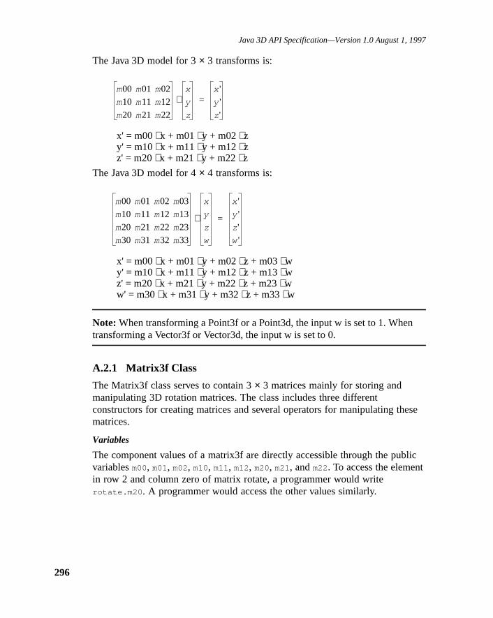
Java 3D API Specification—Version 1.0 August 1, 1997
296
n
ese
lic
The Java 3D model for 3× 3 transforms is:
x' = m00⋅ x + m01⋅ y + m02⋅ zy' = m10⋅ x + m11⋅ y + m12⋅ zz' = m20⋅ x + m21⋅ y + m22⋅ z
The Java 3D model for 4× 4 transforms is:
x' = m00⋅ x + m01⋅ y + m02⋅ z + m03⋅ wy' = m10⋅ x + m11⋅ y + m12⋅ z + m13⋅ wz' = m20⋅ x + m21⋅ y + m22⋅ z + m23⋅ ww' = m30⋅ x + m31⋅ y + m32⋅ z + m33⋅ w
Note: When transforming a Point3f or a Point3d, the input w is set to 1. Whetransforming a Vector3f or Vector3d, the input w is set to 0.
A.2.1 Matrix3f Class
The Matrix3f class serves to contain 3× 3 matrices mainly for storing andmanipulating 3D rotation matrices. The class includes three differentconstructors for creating matrices and several operators for manipulating thmatrices.
Variables
The component values of a matrix3f are directly accessible through the pubvariablesm00, m01, m02, m10, m11, m12, m20, m21, andm22. To access the elementin row 2 and column zero of matrix rotate, a programmer would writerotate.m20 . A programmer would access the other values similarly.
m00 m01 m02
m10 m11 m12
m20 m21 m22
x
y
z
⋅x '
y '
z '
=
m00 m01 m02 m03
m10 m11 m12 m13
m20 m21 m22 m23
m30 m31 m32 m33
x
y
z
w
⋅
x '
y '
z '
w'
=

Math Objects
tor
sed
sedajor first
public float m00public float m01public float m02public float m10public float m11public float m12public float m20public float m21public float m22
The matrix element that maps z into z'.
Constructors
public Matrix3f(float m00, float m01, float m02, float m10,float m11, float m12, float m20, float m21, float m22)
public Matrix3f(float[] v)public Matrix3f(Matrix3d m1)public Matrix3f(Matrix3f m1)public Matrix3f()
These three constructors each return a new Matrix3f. The first constructorgenerates a 3× 3 matrix from the nine values provided. The second construcgenerates a 3× 3 matrix from the first nine values in the arrayv. The third andfourth constructors generate a new matrix with the same values as the pasmatrix m1. The final constructor generates a 3× 3 matrix with all values equal to0.0.
Methods
public final void set(Quat4d q1)public final void set(Quat4f q1)
These twoset methods set the value of the matrixthis to the matrix conversionof the quaternion argumentq1.
public final void set(AxisAngle4d a1)public final void set(AxisAngle4f a1)
These twoset methods set the value of the matrixthis to the matrix conversionof the axis and angle argumenta1.
public final void set(float scale)public final void set(float[] m)
The first method sets the value of this matrix to a scale matrix with the passcale amount. The second method sets the values of this matrix to the row-marray parameter (i.e., the first three elements of the array are copied into therow of this matrix, etc.).
public final void setElement(int row, int column, float value)public final float getElement(int row, int column)
The setElement andgetElement methods provide a means for accessing asingle element within a 3× 3 matrix using indices. This is not a preferred
297

Java 3D API Specification—Version 1.0 August 1, 1997
298
mn 2t in
s
de of
method of accessing but Java 3D provides these functions for functionalcompleteness. ThesetElement method takes a row indexrow (where a value of0 represents the first row and a value of 2 represents the third row), a coluindex column (where a value of 0 represents the first column and a value ofrepresents the third column), and a value. It sets the corresponding elemenmatrix this to the specified value. ThegetElement method also takes a rowindex row and, a column indexcolumn . It returns the element at thecorresponding locations as a floating-point value.
public final void setRow(int row, float x, float y, float z)public final void setRow(int row, Vector3f v)public final void setRow(int row, float v[])
These threesetRow methods provide a means for constructing a 3× 3 matrix ona row basis. The row parameterrow determines which row the methodinvocation affects. A row value of 0 represents the first row and a value of 2represents the third row. The firstsetRow method specifies the three new valueas independent floating-point values. The secondsetRow method uses the valuesin the Vector3fv to update the matrix. The thirdsetRow method uses the firstthree values in the arrayv to update the matrix. In all three cases the matrixaffected is the matrixthis .
public final void setColumn(int column, float x, float y,float z)
public final void setColumn(int column, Vector3f v)public final void setColumn(int column, float v[])
These threesetColumn methods provide a means for constructing a 3× 3 matrixon a column basis. Thecolumn parameter determines which column the methoinvocation affects. A column value of 0 represents the first column and a valu2 represents the third column. The firstsetColumn method specifies the threenew values as independent floating-point values. The secondsetColumn methoduses the values in the Vector3fv to update the matrix. The thirdsetColumn
method uses the first three values in the arrayv to update the matrix. In all threecases the matrix affected is the matrixthis .
public final void setZero()
This method sets this matrix to all zeros.
public final void setIdentity()
This method sets this Matrix3f to identity.
public final void add(Matrix3f m1, Matrix3f m2)public final void add(Matrix3f m1)public final void sub(Matrix3f m1, Matrix3f m2)public final void sub(Matrix3f m1)
The firstadd method adds the matrixm1 to the matrixm2 and places the resultinto the matrixthis . The secondadd method adds the matrixthis to the matrix

Math Objects
ple
he
m1 and places the result into the matrixthis . The firstsub method performs anelement-by-element subtraction of matrixm2 from matrixm1 and places theresult into the matrixthis . The secondsub method performs an element-by-element subtraction of the matrixm1 from the matrixthis and places the resultinto the matrixthis .
public final void transform(Tuple3f t)public final void transform(Tuple3f t, Tuple3f result)
The first method multiplies this matrix by the tuplet and places the result backinto the tuple (t = this*t). The second method multiplies this matrix by the tut and places the result into the tupleresult (result = this*t).
public final void transpose(Matrix3f m1)public final void transpose()
The firsttranspose method transposes the matrixm1 and places the result intothe matrixthis . The secondtranspose method transposes the matrixthis andplaces the transpose back into the matrixthis .
public final void invert()public final void invert(Matrix3f m1)
The invert methods have two forms. In the first form, without an argument,they invert the matrixthis and replacethis with the inverted value. In thesecond form, with an argument, the methods invert the matrixm1 and replace thematrix this with the inverted value. These methods perform a full inversioncomputation.
public final float determinant()
The determinant method computes the determinant of the matrixthis andreturns the computed value.
public final void rotX(float angle)public final void rotY(float angle)public final void rotZ(float angle)
The threerot methods construct rotation matrices that rotate in a clockwisedirection around the axis specified as the last letter of the method name. Tconstructed matrix replaces the value of the matrixthis . The rotation angle isexpressed in radians.
public final void mul(Matrix3f m1, Matrix3f m2)public final void mul(Matrix3f m1)
The firstmul method multiplies matrixm1 with matrix m2 and places the resultinto the matrixthis . The secondmul method multiplies the matrixthis with thematrix m1 and places the result into matrixthis .
299

Java 3D API Specification—Version 1.0 August 1, 1997
300
this
the
j =
rix3f
public final void mulNormalize(Matrix3f m1)public final void mulNormalize(Matrix3f m1, Matrix3f m2)
The firstmulNormalize method multiplies this matrix by matrixm1, performs anSVD normalization of the result, and places the result back into this matrix (= SVDnorm(this⋅ m1)). The secondmulNormalize method multiplies matrixm1 by matrix m2, performs an SVD normalization of the result, and places result into this matrix (this = SVDnorm(m1⋅ m2)).
public final void mulTransposeBoth(Matrix3f m1, Matrix3f m2)public final void mulTransposeRight(Matrix3f m1, Matrix3f m2)public final void mulTransposeLeft(Matrix3f m1, Matrix3f m2)
ThemulTransposeBoth method multiplies the transpose of matrixm1 (left) timesthe transpose of matrixm2 (right) and places the result into this matrix. ThemulTransposeRight method multiplies matrixm1 times the transpose of matrixm2 and places the result back into this matrix. ThemulTransposeLeft methodmultiplies the transpose of matrixm1 times matrixm2 and places the result intothis matrix.
public final void normalize()public final void normalize(Matrix3f m1)
The firstnormalize method performs a singular value decompositionnormalization of this matrix. The secondnormalize method performs a singularvalue decomposition normalization of matrixm1 and places the normalizedvalues intothis .
public final void normalizeCP()public final void normalizeCP(Matrix3f m1)
The firstnormalizeCP method performs a cross product normalization of thismatrix. The secondnormalizeCP method performs a cross productnormalization of matrixm1 and places the normalized values intothis .
public boolean equals(Matrix3f m1)
The equals method returns true if all of the data members of Matrix3fm1 areequal to the corresponding data members in this Matrix3f.
public boolean epsilonEquals(Matrix3f m1, float epsilon)
This method returns true if the L-infinite distance between this Matrix3f andMatrix3f m1 is less than or equal to the epsilon parameter. Otherwise, thismethod returns false. The L-infinite distance is equal to MAX[i = 0,1,2, ... n; 0,1,2,... n; abs(this.m(i,j) – m1.m(i,j)].
public final void negate()public final void negate(Matrix3f m1)
The first method negates the value of this matrix (this = –this). The secondnegate method sets the value of this matrix equal to the negation of the Matparameter.

Math Objects
t the
the
aces
ackple
is
ugh
3f.
ese
public final float getScale()
This method performs an SVD normalization of this matrix to calculate andreturn the uniform scale factor.
public final void setScale(float scale)
This method Sets the scale component of the current matrix by factoring oucurrent scale (by doing an SVD) and multiplying by the new scale.
public final void add(float scalar)
This method adds a scalar to each component of this matrix.
public final void add(float scalar, Matrix3f m1)
This method adds a scalar to each component of the matrix m1 and placesresult into this. Matrix m1 is not modified.
public final void mul(float scalar, Matrix3f m1)
This method multiplies each component of the matrix m1 by a scalar and plthe result into this. Matrix m1 is not modified.
public final void mul(float scalar)
This method multiplies each element of this matrix by a scalar.
public final void transform(Tuple3f t)public final void transform(Tuple3f t, Tuple3f result)
The first method multiplies this matrix by the tuple t and places the result binto the tuple (t = this*t). The second method multiplies this matrix by the tut and places the result into the tupleresult (result = this*t).
public int hashCode()
The hashCode method returns a hash number based on the data values in thobject. Two different Matrix3f objects with identical data values (i.e., returnstrue forequals(Matrix3f) ) will return the same hash number. Two Matrix3fobjects with different data members may return the same hash value, althothis is not likely.
public String toString()
The toString method returns a string that contains the values of this Matrix
A.2.2 Matrix3d Class
The Matrix3d class serves to contain 3× 3 matrices mainly for storing andmanipulating 3D rotation matrices. The class includes three differentconstructors for creating matrices and several operators for manipulating thmatrices.
301

Java 3D API Specification—Version 1.0 August 1, 1997
302
blic
ld
tes ates a
Variables
The component values of a matrix3d are directly accessible through the puvariablesm00, m01, m02, m10, m11, m12, m20, m21, andm22. To access the elementin row two and column zero of the matrix named rotate, a programmer wouwrite rotate.m20 . Other matrix values are accessed similarly.
public double m00public double m01public double m02public double m10public double m11public double m12public double m20public double m21public double m22
Constructors
public Matrix3d(double m00, double m01, double m02, double m10,double m11, double m12, double m20, double m21,double m22)
public Matrix3d(double[] v)public Matrix3d()public Matrix3d(Matrix3d m1)public Matrix3d(Matrix3f m1)
These constructors each return a new Matrix3d. The first constructor genera3 × 3 matrix from the nine values provided. The second constructor genera3 × 3 matrix from the first nine values in the arrayv. The third constructorgenerates a 3× 3 matrix with all values equal to 0.0. The fourth and fifthconstructors generate a 3× 3 matrix with the same values as the matrixm1
parameter.
Methods
public final void set(Matrix3f m1)
This method sets the value of the matrixthis to the float value of the rotationalcomponents of the passed matrixm1.
public final void set(double scale)public final void set(double[] m)
These methods set the value of the matrixthis to a scale matrix with the passedscale amount.
public final void set(AxisAngle4d a1)public final void set(AxisAngle4f a1)
These twoset methods set the value of the matrixthis to the matrix conversionof the axis and angle argumenta1.

Math Objects
mn 2t in
s theentdetrix
de of
public final void set(Quat4d q1)public final void set(Quat4f q1)
These twoset methods set the value of the matrixthis to the matrix conversionof the quaternion argumentq1.
public final void setElement(int row, int column, double value)public final double getElement(int row, int column)
The setElement andgetElement methods provide a means for accessing asingle element within a 3× 3 matrix using indices. This is not a preferredmethod of accessing but Java 3D provides these functions for functionalcompleteness. ThesetElement method takes a row indexrow (where a value of0 represents the first row and a value of 2 represents the third row), a coluindex column (where a value of 0 represents the first column and a value ofrepresents the third column), and a value. It sets the corresponding elemenmatrix this to the specified value. ThegetElement method also takes a rowindex row and, a column indexcolumn and returns the element at thecorresponding locations as a floating-point value.
public final void setRow(int row, double x, double y, double z)public final void setRow(int row, Vector3d v)public final void setRow(int row, double v[])
These threesetRow methods provide a means for constructing a 3× 3 matrix ona row basis. Therow parameter determines which row the method invocationaffects. A row value of 0 represents the first row and a value of 2 representthird row. The firstsetRow method specifies the three new values as independfloating-point values. The secondsetRow method uses the values in the Vector3v to update the matrix. The thirdsetRow method uses the first three values in tharrayv to update the matrix. In all three cases the matrix affected is the mathis .
public final void setColumn(int column, double x, double y,double z)
public final void setColumn(int column, Vector3d v)public final void setColumn(int column, double v[])
These threesetColumn methods provide a means for constructing a 3× 3 matrixon a column basis. Thecolumn parameter determines which column the methoinvocation affects. A column value of 0 represents the first column and a valu2 represents the third column. The firstsetColumn method specifies the threenew values as independent floating-point values. The secondsetColumn methoduses the values in the Vector3dv to update the matrix. The thirdsetColumn
method uses the first three values in the arrayv to update the matrix. In all threecases the matrix affected is the matrixthis .
303

Java 3D API Specification—Version 1.0 August 1, 1997
304
ple
he
public final void add(Matrix3d m1, Matrix3d m2)public final void add(Matrix3d m1)public final void sub(Matrix3d m1, Matrix3d m2)public final void sub(Matrix3d m1)
The firstadd method adds the matrixm1 to the matrixm2 and places the resultinto the matrixthis . The secondadd method adds the matrixthis to the matrixm1 and places the result into the matrixthis . The firstsub method performs anelement-by-element subtraction of matrixm2 from matrixm1 and places theresult into the matrixthis . The secondsub method performs an element-by-element subtraction of the matrixm1 from the matrixthis and places the resultinto the matrixthis .
public final void transform(Tuple3d t)public final void transform(Tuple3d t, Tuple3d result)
The first method multiplies this matrix by the tuplet and places the result backinto the tuple (t = this*t). The second method multiplies this matrix by the tut and places the result into the tupleresult (result = this*t).
public final void transpose(Matrix3d m1)public final void transpose()
The firsttranspose method transposes the matrixm1 and places the result intothe matrixthis . The secondtranspose method transposes the matrixthis andplaces the transpose back into the matrixthis .
public final void invert()public final void invert(Matrix3d m1)
The invert methods have two forms. In the first form, without an argument,they invert the matrixthis and replacethis with the inverted value. In thesecond form, with an argument, the methods invert the matrixm1 and replace thematrix this with the inverted value.
public final double determinant()
The determinant method computes the determinant of the matrixthis andreturns the computed value.
public final void rotX(double angle)public final void rotY(double angle)public final void rotZ(double angle)
The threerot methods construct rotation matrices that rotate in a clockwisedirection around the axis specified by the final letter of the method name. Tconstructed matrix replaces the value of the matrixthis . The rotation angle isexpressed in radians.
Math Objects
this
the
public final void mul(Matrix3d m1, Matrix3d m2)public final void mul(Matrix3d m1)
The firstmul method multiplies matrixm1 with matrix m2 and places the resultinto the matrixthis . The secondmul method multiplies matrixthis with matrixm1 and places the result into the matrixthis .
public final void mulNormalize(Matrix3d m1)public final void mulNormalize(Matrix3d m1, Matrix3d m2)
The firstmulNormalize method multiplies this matrix by matrixm1, performs anSVD normalization of the result, and places the result back into this matrix (= SVDnorm(this⋅ m1)). The secondmulNormalize method multiplies matrixm1 by matrix m2, performs an SVD normalization of the result, and places result into this matrix (this = SVDnorm(m1⋅ m2)).
public final void mulTransposeBoth(Matrix3d m1, Matrix3d m2)public final void mulTransposeRight(Matrix3d m1, Matrix3d m2)public final void mulTransposeLeft(Matrix3d m1, Matrix3d m2)
ThemulTransposeBoth method multiplies the transpose of matrixm1 (left) timesthe transpose of matrixm2 (right) and places the result into this matrix. ThemulTransposeRight method multiplies matrixm1 times the transpose of matrixm2 and places the result back into this matrix. ThemulTransposeLeft methodmultiplies the transpose of matrixm1 times matrixm2 and places the result intothis matrix.
public final void normalize()public final void normalize(Matrix3d m1)
The firstnormalize method performs a singular value decompositionnormalization of this matrix. The secondnormalize method performs a singularvalue decomposition normalization of matrixm1 and places the normalizedvalues intothis .
public final void normalizeCP()public final void normalizeCP(Matrix3d m1)
The firstnormalizeCP method performs a cross product normalization of thismatrix. The secondnormalizeCP method performs a cross productnormalization of matrixm1 and places the normalized values intothis .
public boolean equals(Matrix3d m1)
The equals method returns true if all of the data members of Matrix3dm1 areequal to the corresponding data members in this Matrix3d.
public boolean epsilonEquals(Matrix3d m1, double epsilon)
This method returns true if the L-infinite distance between this Matrix3d andMatrix3d m1 is less than or equal to the epsilon parameter. Otherwise, thismethod returns false. The L-infinite distance is equal to MAX[i = 0,1,2,; j =0,1,2,; abs(this.m(i,j) – m1.m(i,j)].
305

Java 3D API Specification—Version 1.0 August 1, 1997
306
rix3d
t the
the
aces
ackple
iss
ugh
public final void negate()public final void negate(Matrix3d m1)
The first method negates the value of this matrix (this = –this). The secondnegate method sets the value of this matrix equal to the negation of the Matparameter.
public final double getScale()
This method performs an SVD normalization of this matrix to calculate andreturn the uniform scale factor.
public final void setScale(double scale)
This method Sets the scale component of the current matrix by factoring oucurrent scale (by doing an SVD) and multiplying by the new scale.
public final void add(double scalar)
This method adds a scalar to each component of this matrix.
public final void add(double scalar, Matrix3d m1)
This method adds a scalar to each component of the matrix m1 and placesresult into this. Matrix m1 is not modified.
public final void mul(double scalar, Matrix3d m1)
This method multiplies each component of the matrix m1 by a scalar and plthe result into this. Matrix m1 is not modified.
public final void mul(double scalar)
This method multiplies each element of this matrix by a scalar.
public final void transform(Tuple3d t)public final void transform(Tuple3d t, Tuple3d result)
The first method multiplies this matrix by the tuple t and places the result binto the tuple (t = this*t). The second method multiplies this matrix by the tut and places the result into the tupleresult (result = this*t).
public final void setZero()
This method sets this matrix to all zeros.
public final void setIdentity()
This method sets this Matrix3d to identity.
public int hashCode()
The hashCode method returns a hash number based on the data values in thobject. Two different Matrix3d objects with identical data values (i.e., returntrue forequals(Matrix3d) ) will return the same hash number. Two Matrix3dobjects with different data members may return the same hash value, althothis is not likely.

Math Objects
3d.
ese
lic
te,er
r
e
public String toString()
The toString method returns a string that contains the values of this Matrix
A.2.3 Matrix4f Class
The Matrix4f class serves to contain 4× 4 matrices mainly for storing andmanipulating 3D transform matrices. The class includes three differentconstructors for creating matrices and several operators for manipulating thmatrices.
Variables
The component values of a matrix4f are directly accessible through the pubvariablesm00, m01, m02, m03, m10, m11, m12, m13, m20, m21, m22, m23, m30, m31,m32, andm33. To access the element in row 2 and column zero of matrix rotaa programmer would write rotate.m20. A programmer would access the othvalues similarly.
public float m00public float m01public float m02public float m03public float m10public float m11public float m12public float m13public float m20public float m21public float m22public float m23public float m30public float m31public float m32public float m33
Constructors
public Matrix4f(float m00, float m01, float m02, float m03,float m10, float m11, float m12, float m13, float m20,float m21, float m22, float m23, float m30, float m31,float m32, float m33)
public Matrix4f(float[] v)public Matrix4f(Quat4f q1, Vector3f t1, float s)public Matrix4f(Matrix4d m1)public Matrix4f(Matrix4f m1)public Matrix4f(Matrix3f m1, Vector3f t1, float s)public Matrix4f()
These three constructors each return a new Matrix4f. The first constructorgenerates a 4× 4 matrix from the 16 values provided. The second constructogenerates a 4× 4 matrix from the first 16 values in the arrayv. The thirdconstructor generates a 4× 4 matrix from the quaternion, translation, and scal
307

Java 3D API Specification—Version 1.0 August 1, 1997
308
ix
ts
of
fthe
sedajor
first
ed
values. The scale is applied only to the rotational components of the matrix(upper 3x3) and not to the translational components. The fourth and fifthconstructors generate a 4× 4 matrix with the same values as the passed matrm1. The sixth constructor generates a 4× 4 matrix from the rotation matrix,translation, and scale values. The scale is applied only to the rotationalcomponents of the matrix (upper 3× 3) and not to the translational componenof the matrix. The final constructor generates a 4× 4 matrix with all values equalto 0.0.
Methods
public final void set(Quat4f q1)public final void set(Quat4d q1)public final void set(Quat4f q1, Vector3f t1, float s)public final void set(Quat4d q1, Vector3d t1, double s)public final void set(Matrix4d m1)public final void set(Matrix4f m1)public final void set(AxisAngle4f a1)public final void set(AxisAngle4d a1)
The first twoset methods set the value of this matrix to the matrix conversionthe quaternion argumentq1. The next twoset methods set the value of thismatrix from the rotation expressed by the quaternionq1, the translationt1 , andthe scales. The next twoset methods set the value of this matrix to a copy othe passed matrixm1. The last two set methods set the value of this matrix to matrix conversion of the axis and angle argumenta1.
public final void set(Matrix3f m1)public final void set(Matrix3d m1)
These methods set the rotational component (upper 3× 3) of this matrix to thematrix values in them1 argument. The other elements of this matrix areinitialized as if this were an identity matrix (i.e., affine matrix with notranslational component).
public final void set(float scale)public final void set(float[] m)
The first method sets the value of this matrix to a scale matrix with the passcale amount. The second method sets the value of this matrix to the row-marray parameter (i.e., the first four elements of the array are copied into therow of this matrix, etc.).
public final void set(Vector3f v1)
This method sets the value of this matrix to a translate matrix with the passtranslation value.

Math Objects
atrix.atrixscale
by not
toe
.DThe
for
row),
ding
o
public final void set(float scale, Vector3f t1)public final void set(Vector3f t1, float scale)
These methods set the value of this transform to a scale and translation mIn the first method, the scale is not applied to the translation and all of the mvalues are modified. In the second method the translation is scaled by the factor and all of the matrix values are modified.
public final void set(Matrix3f m1, Vector3f t1, float scale)public final void set(Matrix3d m1, Vector3d t1, double scale)
These two methods set the value of this matrix from the rotation expressedthe rotation matrix m1, the translation t1, and the scale s. The translation ismodified by the scale.
public final void get(Matrix3d m1)public final void get(Matrix3f m1)public final float get(Matrix3f m1, Vector3f t1)public final void get(Quat4f q1)public final void get(Vector3f trans)
The first two methods perform an SVD normalization of this matrix in orderacquire the normalized rotational component. The values are placed into thmatrix parameterm1. The third method performs an SVD normalization of thismatrix to calculate the rotation as a 3× 3 matrix, the translation, and the scaleNone of the matrix values are modified. The fourth method performs an SVnormalization of this matrix to acquire the normalized rotational component. values are placed into the Quat4f parameter. The final method retrieves thetranslational components of this matrix.
public final void setElement(int row, int column, float value)public final float getElement(int row, int column)
The setElement andgetElement methods provide a means for accessing asingle element within a 4× 4 matrix using indices. This is not a preferredmethod of accessing matrix elements but Java 3D provides these functionsfunctional completeness. ThesetElement method takes a row indexrow (wherea value of 0 represents the first row and a value of 3 represents the fourth a column indexcolumn (where a value of 0 represents the first column and avalue of 3 represents the fourth column), and a value. It sets the corresponelement in matrixthis to the specified value. ThegetElement method alsotakes a row indexrow and, a column indexcolumn and returns the element at thecorresponding locations as a floating-point value.
public final void getRotationScale(Matrix3f m1)
This method retrieves the upper 3× 3 values of this matrix and places them intthe matrixm1.
309

Java 3D API Specification—Version 1.0 August 1, 1997
310
t the
the
aces
s
de of
nd
public final float getScale()
This method performs an SVD normalization of this matrix to calculate andreturn the uniform scale factor.
public final void setScale(float scale)
This method Sets the scale component of the current matrix by factoring oucurrent scale (by doing an SVD) and multiplying by the new scale.
public final void add(float scalar)
This method adds a scalar to each component of this matrix.
public final void add(float scalar, Matrix4f m1)
This method adds a scalar to each component of the matrix m1 and placesresult into this. Matrix m1 is not modified.
public final void mul(float scalar, Matrix4f m1)
This method multiplies each component of the matrix m1 by a scalar and plthe result into this. Matrix m1 is not modified.
public final void mul(float scalar)
This method multiplies each element of this matrix by a scalar.
public final void setRow(int row, float x, float y, float z,float w)
public final void setRow(int row, Vector4f v)public final void setRow(int row, float v[])
These threesetRow methods provide a means for constructing a 4× 4 matrix ona row basis. The row parameterrow determines which row the methodinvocation affects. A row value of 0 represents the first row and a value of 3represents the fourth row. The firstsetRow method specifies the four new valueas independent floating-point values. The secondsetRow method uses the valuesin the Vector4fv to update the matrix. The thirdsetRow method uses the firstfour values in the arrayv to update the matrix. In all three cases the matrixaffected is the matrixthis .
public final void setColumn(int column, float x, float y,float z, float w)
public final void setColumn(int column, Vector4f v)public final void setColumn(int column, float v[])
These threesetColumn methods provide a means for constructing a 4× 4 matrixon a column basis. Thecolumn parameter determines which column the methoinvocation affects. A column value of 0 represents the first column and a valu3 represents the fourth column. The firstsetColumn method specifies the fournew values as independent double-precision floating-point values. The secosetColumn method uses the values in the Vector4fv to update the matrix. The

Math Objects
e
In thect's
n thelar
e
s of
third setColumn method uses the first four values in the arrayv to update thematrix. In all three cases the matrix affected is the matrixthis .
public final void setRotation(Matrix3d m1)public final void setRotation(Matrix3f m1)public final void setRotation(Quat4f q1)public final void setRotation(Quat4d q1)public final void setRotation(AxisAngle4f a1)
These methods set the rotational component (upper 3× 3) of this matrix to thematrix values in the passed argument. The other elements of this matrix arunchanged. In the first two methods, a singular value decomposition isperformed on this object's upper 3× 3 matrix to factor out the scale, then thisobject's upper 3× 3 matrix components are replaced by the passed rotationcomponents, and then the scale is reapplied to the rotational components. next two methods, a singular value decomposition is performed on this objeupper 3× 3 matrix to factor out the scale, then this object's upper 3× 3 matrixcomponents are replaced by the matrix equivalent of the quaternion, and thescale is reapplied to the rotational components. In the last method, a singuvalue decomposition is performed on this object's upper 3× 3 matrix to factorout the scale, then this object's upper 3× 3 matrix components are replaced bythe matrix equivalent of the axis-angle, and then the scale is reapplied to throtational components.
public final void setRotationScale(Matrix3f m1)
This method replaces the upper 3× 3 matrix values of this matrix with the valuesin the matrix m1.
public final void setTranslation(Vector3f trans)
This method modifies the translational components of this matrix to the valuethe Vector3f argument. The other values of this matrix are not modified.
public final void setIdentity()
This method sets this Matrix4f to identity.
public final void setZero()
This method sets this matrix to all zeros.
public final void add(Matrix4f m1, Matrix4f m2)public final void add(Matrix4f m1)public final void sub(Matrix4f m1, Matrix4f m2)public final void sub(Matrix4f m1)
The firstadd method adds the matrixm1 to the matrixm2 and places the resultinto the matrixthis . The secondadd method adds the matrixthis to the matrixm1 and places the result into the matrixthis . The firstsub method performs anelement-by-element subtraction of matrixm2 from matrixm1 and places theresult into the matrixthis . The secondsub method performs an element-by-
311

Java 3D API Specification—Version 1.0 August 1, 1997
312
element subtraction of the matrixm1 from the matrixthis and places the resultinto the matrixthis .
public final void transpose(Matrix4f m1)public final void transpose()
The firsttranspose method transposes the matrixm1 and places the result intothe matrixthis . The secondtranspose method transposes the matrixthis andplaces the result back into the matrixthis .
public final void transform(Point3f point)public final void transform(Point3f point, Point3f pointOut)
The firsttransform method postmultiplies this Matrix4d by thepoint value andplaces the result back intopoint . The multiply treats the three-vectorpoint as ifits fourth element were one. The secondtransform method transforms thisMatrix4d by thepoint argument and places the value intopointOut .
public final void transform(Vector3f normal)public final void transform(Vector3f normal, Vector3f normalOut)
The firsttransform method transforms this matrix by thenormal argument andplaces the value back intonormal . The multiply treats the three-vectornormal asif its fourth element were zero. The secondtransform method postmultipliesthis matrix by the vectornormal and places the value intonormalOut .
public final void transform(Tuple4f vec)public final void transform(Tuple4f vec, Tuple4f vecOut)
The firsttransform method transforms this matrix by the tuplevec and placesthe value back intovec . The secondtransform method postmultiplies thismatrix by the tuplevec and places the value intovecOut .
public final void negate()public final void negate(Matrix4f m1)
The first method negates the value of this matrix (this = –this). The secondmethod sets the value of this matrix equal to the negation of the Matrix4fparameter.
public final void invert()public final void invert(Matrix4f m1)
The first method inverts the matrixthis and replacesthis with the invertedvalue. The second method inverts the matrixm1 and replaces the matrixthis
with the inverted value.
public final float determinant()
The determinant method computes the determinant of the matrixthis andreturns the computed value.

Math Objects
he
is
ugh
4f.
public final void rotX(float angle)public final void rotY(float angle)public final void rotZ(float angle)
The threerot methods construct rotation matrices that rotate in a clockwisedirection around the axis specified as the last letter of the method name. Tconstructed matrix replaces the value of the matrixthis . The rotation angle isexpressed in radians.
public final void mul(Matrix4f m1, Matrix4f m2)public final void mul(Matrix4f m1)
The firstmul method multiplies matrixm1 with matrix m2 and places the resultinto the matrixthis . The secondmul method multiplies the matrixthis withmatrix m1 and places the result in matrixthis .
public final void mulTransposeBoth(Matrix4f m1, Matrix4f m2)public final void mulTransposeRight(Matrix4f m1, Matrix4f m2)public final void mulTransposeLeft(Matrix4f m1, Matrix4f m2)
ThemulTransposeBoth method multiplies the transpose of matrixm1 (left) timesthe transpose of matrixm2 (right) and places the result into this matrix. ThemulTransposeRight method multiplies matrixm1 times the transpose of matrixm2 and places the result back into this matrix. ThemulTransposeLeft methodmultiplies the transpose of matrixm1 times matrixm2 and places the result intothis matrix.
public boolean equals(Matrix4f m1)
The equals method returns true if all of the data members of Matrix4fm1 areequal to the corresponding data members in this Matrix4f.
public boolean epsilonEquals(Matrix4f m1, float epsilon)
This method returns true if the L-infinite distance between this Matrix4f andMatrix4f m1 is less than or equal to theepsilon parameter. Otherwise, thismethod returns false. The L-infinite distance is equal to MAX[i = 0,1,2,3; j =0,1,2,3; abs(this.m(i,j) – m1.m(i,j)].
public int hashCode()
The hashCode method returns a hash number based on the data values in thobject. Two different Matrix4f objects with identical data values (i.e., returnstrue forequals(Matrix4f) ) will return the same hash number. Two Matrix4fobjects with different data members may return the same hash value, althothis is not likely.
public String toString()
The toString method returns a string that contains the values of this Matrix
313

Java 3D API Specification—Version 1.0 August 1, 1997
314
ese
blic
ate,r
r
datrix
A.2.4 Matrix4d Class
The Matrix4d class serves to contain 4× 4 matrices mainly for storing andmanipulating 3D transform matrices. The class includes three differentconstructors for creating matrices and several operators for manipulating thmatrices.
Variables
The component values of a matrix4d are directly accessible through the puvariablesm00, m01, m02, m03, m10, m11, m12, m13, m20, m21, m22, m23, m30, m31,m32, andm33. To access the element in row 2 and column zero of matrix rota programmer would writerotate.m20 . A programmer would access the othevalues similarly.
public double m00public double m01public double m02public double m03public double m10public double m11public double m12public double m13public double m20public double m21public double m22public double m23public double m30public double m31public double m32public double m33
Constructors
public Matrix4d(double m00, double m01, double m02, double m03,double m10, double m11, double m12, double m13,double m20, double m21, double m22, double m23,double m30, double m31, double m32, double m33)
public Matrix4d(double[] v)public Matrix4d(Quat4d q1, Vector3d t1, double s)public Matrix4d(Quat4f q1, Vector3d t1, double s)public Matrix4d(Matrix3f m1, Vector3d t1, double s)public Matrix4d(Matrix3d m1, Vector3d t1, double s)public Matrix4d(Matrix4d m1)public Matrix4d(Matrix4f m1)public Matrix4d()
These three constructors each return a new Matrix4d. The first constructorgenerates a 4× 4 matrix from the 16 values provided. The second constructogenerates a 4× 4 matrix from the first 16 values in the arrayv. The third throughsixth constructors generates a 4× 4 matrix from the quaternion, translation, anscale values. The scale is applied only to the rotational components of the m

Math Objects
thix.
toe this.VD
The
for
row),
ding
s theentdetrix
(upper 3× 3) and not to the translational components. The seventh and eighconstructors generate a 4× 4 matrix with the same values as the passed matrThe final constructor generates a 4× 4 matrix with all values equal to 0.0.
Methods
public final void get(Matrix3d m1)public final void get(Matrix3f m1)public final double get(Matrix3d m1, Vector3d t1)public final double get(Matrix3f m1, Vector3d t1)public final void get(Quat4f q1)public final void get(Quat4d q1)public final void get(Vector3d trans)
The first two methods perform an SVD normalization of this matrix in orderacquire the normalized rotational component. The values are placed into thpassed parameter. The next two methods perform an SVD normalization ofmatrix to calculate the rotation as a 3× 3 matrix, the translation, and the scaleNone of the matrix values are modified. The next two methods perform an Snormalization of this matrix to acquire the normalized rotational component. last two methods retrieve the translational components of this matrix.
public final void setElement(int row, int column, double value)public final double getElement(int row, int column)
The setElement andgetElement methods provide a means for accessing asingle element within a 4× 4 matrix using indices. This is not a preferredmethod of accessing matrix elements but Java 3D provides these functionsfunctional completeness. ThesetElement method takes a row indexrow (wherea value of 0 represents the first row and a value of 3 represents the fourth a column indexcolumn (where a value of 0 represents the first column and avalue of 3 represents the fourth column), and a value. It sets the corresponelement in matrixthis to the specified value. ThegetElement method alsotakes a row indexrow and a column indexcolumn and returns the element at thecorresponding locations as a floating-point value.
public final void setRow(int row, double x, double y, double z,double w)
public final void setRow(int row, Vector4d v)public final void setRow(int row, double v[])
These threesetRow methods provide a means for constructing a 4× 4 matrix ona row basis. Therow parameter determines which row the method invocationaffects. A row value of 0 represents the first row and a value of 3 representfourth row. The firstsetRow method specifies the four new values as independfloating-point values. The secondsetRow method uses the values in the Vector4v to update the matrix. The thirdsetRow method uses the first four values in tharrayv to update the matrix. In all three cases the matrix affected is the mathis .
315

Java 3D API Specification—Version 1.0 August 1, 1997
316
de of
nd
eper 3
scale
eper 3
n the
x areper 3
n the
public final void setColumn(int column, double x, double y,double z, double w)
public final void setColumn(int column, Vector4d v)public final void setColumn(int column, double v[])
These threesetColumn methods provide a means for constructing a 4× 4 matrixon a column basis. Thecolumn parameter determines which column the methoinvocation affects. A column value of 0 represents the first column and a valu3 represents the fourth column. The firstsetColumn method specifies the fournew values as independent double-precision floating-point values. The secosetColumn method uses the values in the Vector4dv to update the matrix. Thethird setColumn method uses the first four values in the arrayv to update thematrix. In all three cases the matrix affected is the matrixthis .
public final void setRotation(Matrix3f m1)public final void setRotation(Matrix3d m1)
These methods set the rotational component (upper 3× 3) of this matrix to thematrix values in the passed argument. The other elements of this matrix arunchanged. A singular value decomposition is performed on this object's up× 3 matrix to factor out the scale, then this object’s upper 3× 3 matrixcomponents are replaced by the passed rotation components, and then theis reapplied to the rotational components.
public final void setRotation(Quat4f q1)public final void setRotation(Quat4d q1)
These methods set the rotational component (upper 3× 3) of this matrix to thematrix values in the passed argument. The other elements of this matrix arunchanged. A singular value decomposition is performed on this object's up× 3 matrix to factor out the scale, then this object’s upper 3× 3 matrixcomponents are replaced by the matrix equivalent of the quaternion, and thescale is reapplied to the rotational components.
public final void setRotation(AxisAngle4d a1)
This method sets the rotational component (upper 3× 3) of this matrix to theequivalent values in the passed argument. The other elements of this matriunchanged. A singular value decomposition is performed on this object's up× 3 matrix to factor out the scale, then this object’s upper 3× 3 matrixcomponents are replaced by the matrix equivalent of the axis-angle, and thescale is reapplied to the rotational components.

Math Objects
s of
t the
the
aces
public final void getRotationScale(Matrix3f m1)public final void getRotationScale(Matrix3d m1)public final void setRotationScale(Matrix3d m1)public final void setRotationScale(Matrix3f m1)
The two get methods retrieve the upper 3× 3 values of this matrix and placethem into the matrixm1. The two set methods replace the upper 3× 3 matrixvalues of this matrix with the values in the matrixm1.
public final void setTranslation(Vector3d trans)
This method modifies the translational components of this matrix to the valuethe Vector3d argument. The other values of this matrix are not modified.
public final double getScale()
This method performs an SVD normalization of this matrix to calculate andreturn the uniform scale factor.
public final void setScale(double scale)
This method Sets the scale component of the current matrix by factoring oucurrent scale (by doing an SVD) and multiplying by the new scale.
public final void add(double scalar)
This method adds a scalar to each component of this matrix.
public final void add(double scalar, Matrix4d m1)
This method adds a scalar to each component of the matrix m1 and placesresult into this. Matrix m1 is not modified.
public final void mul(double scalar, Matrix4d m1)
This method multiplies each component of the matrix m1 by a scalar and plthe result into this. Matrix m1 is not modified.
public final void mul(double scalar)
This method multiplies each element of this matrix by a scalar.
public final void add(Matrix4d m1, Matrix4d m2)public final void add(Matrix4d m1)public final void sub(Matrix4d m1, Matrix4d m2)public final void sub(Matrix4d m1)
The firstadd method adds the matrixm1 to the matrixm2 and places the resultinto the matrixthis . The secondadd method adds the matrixthis to the matrixm1 and places the result into the matrixthis . The firstsub method performs anelement-by-element subtraction of matrixm2 from matrixm1 and places theresult into the matrixthis . The secondsub method performs an element-by-element subtraction of the matrixm1 from the matrixthis and places the resultinto the matrixthis .
317

Java 3D API Specification—Version 1.0 August 1, 1997
318
(i.e.,rix,
ix
xis
d
the
scale
ix.
public final void set(double[] m)
This method sets the value of this matrix to the row-major array parameter the first four elements of the array will be copied into the first row of this matetc.).
public final void set(Matrix3f m1)public final void set(Matrix3d m1)
These methods set the rotational component (upper 3× 3) of this matrix to thematrix values in the matrix argument. The other elements of this matrix areinitialized as if this were an identity matrix (i.e., affine matrix with notranslational component).
public final void set(Matrix4f m1)public final void set(Matrix4d m1)
These methods set the value of this matrix to the value of the passed matrm1.
public final void set(Quat4d q1)public final void set(Quat4f q1)
These methods set the value of this matrix to the matrix conversion of thequaternion argument.
public final void set(AxisAngle4d a1)public final void set(AxisAngle4f a1)
These methods set the value of this matrix to the matrix conversion of the aand angle argument.
public final void set(Vector3d v1)
This method sets the value of this matrix to a translate matrix by the passetranslation value.
public final void set(Quat4d q1, Vector3d t1, double s)public final void set(Quat4f q1, Vector3d t1, double s)public final void set(Quat4f q1, Vector3f t1, float s)
These methods set the value of this matrix from the rotation expressed by quaternionq1, the translationt1 , and the scales.
public final void set(double scale)
This method sets the value of this matrix to a scale matrix with the passed amount.
public final void set(double scale, Vector3d v1)
This method sets the value of this transform to a scale and translation matrThe scale is not applied to the translation and all of the matrix values aremodified.

Math Objects
ix.
the
–
public final void set(Vector3d v1, double scale)
This method sets the value of this transform to a scale and translation matrThe translation is scaled by the scale factor and all of the matrix values aremodified.
public final void set(Matrix3f m1, Vector3f t1, float scale)public final void set(Matrix3d m1, Vector3d t1, double scale)
These methods set the value of this matrix from the rotation expressed by rotation matrixm1, the translationt1 , and the scales.
public final void negate(Matrix4d m1)public final void negate()
The firstnegate method sets the value of this matrix to the negation of them1
parameter. The secondnegate method negates the value of this matrix (this =this).
public final void transpose(Matrix4d m)public final void transpose()
The firsttranspose method transposes the matrixm and places the result into thematrix this . The secondtranspose method transposes the matrixthis andplaces the result back into the matrixthis .
public final void transform(Tuple4d vec)public final void transform(Tuple4f vec)public final void transform(Tuple4d vec, Tuple4d vecOut)public final void transform(Tuple4f vec, Tuple4f vecOut)
The first twotransform methods postmultiply the matrixthis by the tuplevec
and place the result back intovec . The second twotransform methodspostmultiply the matrixthis by the tuplevec and place the result intovecOut .
public final void transform(Point3d point)public final void transform(Point3f point)public final void transform(Point3d point, Point3d pointOut)public final void transform(Point3f point, Point3f pointOut)
The first twotransform methods postmultiply this Matrix4d by thepoint andplace the result back intopoint . The multiply treats the three-vectorpoint as ifits fourth element were one. The second twotransform methods transform thisMatrix4d by thepoint argument and place the value intopointOut .
public final void transform(Vector3d normal)public final void transform(Vector3f normal)public final void transform(Vector3d normal, Vector3d normalOut)public final void transform(Vector3f normal, Vector3f normalOut)
The first twotransform methods transform this matrix by thenormal argumentand place the value back intonormal . The multiply treats the three-vectornormal as if its fourth element were zero. The last twotransform methods
319

Java 3D API Specification—Version 1.0 August 1, 1997
320
tionucted
postmultiply this matrix by the vectornormal and place the value intonormalOut .
public final void invert()public final void invert(Matrix4d m1)
The firstinvert method inverts the matrixthis and replacesthis with theinverted value. The secondinvert method inverts the matrixm1 and replaces thematrix this with the inverted value.
public final double determinant()
The determinant method computes the determinant of the matrixthis andreturns the computed value.
public final void rotX(double angle)public final void rotY(double angle)public final void rotZ(double angle)
The rot methods construct rotation matrices that rotate in a clockwise direcaround the axis specified as the last letter of the method name. The constrmatrix replaces the value of the matrixthis . The rotation angle is expressed inradians.
public final void mul(Matrix4d m1, Matrix4d m2)public final void mul(Matrix 4d m1)
The firstmul method multiplies matrixm1 with matrix m2 and places the resultinto the matrixthis . The secondmul method multiplies matrixthis with matrixm1 and places the result into the matrixthis .
public final void mulTransposeBoth(Matrix4d m1, Matrix4d m2)public final void mulTransposeRight(Matrix4d m1, Matrix4d m2)public final void mulTransposeLeft(Matrix4d m1, Matrix4d m2)
ThemulTransposeBoth method multiplies the transpose of matrixm1 (left) timesthe transpose of matrixm2 (right) and places the result into this matrix. ThemulTransposeRight method multiplies matrixm1 times the transpose of matrixm2 and places the result back into this matrix. ThemulTransposeLeft methodmultiplies the transpose of matrixm1 times matrixm2 and places the result intothis matrix.
public final void setZero()
This method sets this matrix to all zeros.
public final void setIdentity()
This method sets this Matrix4d to identity.
public boolean equals(Matrix4d m1)
The equals method returns true if all of the data members of Matrix4dm1 areequal to the corresponding data members in this Matrix4d.

Math Objects
nd
=
iss
ugh
4d.
oflic
es an
public boolean epsilonEquals(Matrix4d m1, float epsilon)
This method returns true if the L – infinite distance between this Matrix4d aMatrix4d m1 is less than or equal to theepsilon parameter. Otherwise, thismethod returns false. The L –infinite distance is equal to MAX[i = 0,1,2,3; j 0,1,2,3; abs(this.m(i,j) – m1.m(i,j)].
public int hashCode()
The hashCode method returns a hash number based on the data values in thobject. Two different Matrix4d objects with identical data values (i.e., returntrue forequals(Matrix4d) ) will return the same hash number. Two Matrix4dobjects with different data members may return the same hash value, althothis is not likely.
public String toString()
The toString method returns a string that contains the values of this Matrix
A.2.5 GMatrix Class
The GMatrix class serves to contain a double-precision, general, anddynamically resizeable M× N matrix. Row and column numbering begins withzero. The representation is row major.
The GMatrix data members are not public to allow efficient implementationssparse matrices. However, the data members can be modified through pubaccessors.
Constructors
public GMatrix(int nRow, int nCol)public GMatrix(int nRow, int nCol, double[] matrix)public GMatrix(GMatrix matrix)
These constructors each return a new GMatrix. The first constructor generatnRow by nCol identity matrix. The second constructor generates annRow by nCol
matrix initialized to the values in the arraymatrix . The last constructorgenerates a new GMatrix and copies the initial values from the parametermatrix argument.
Methods
public final void mul(GMatrix m1, GMatrix m2)public final void mul(GMatrix m1)
The firstmul method multiplies matrixm1 with matrix m2 and places the resultinto this . The secondmul method multiplies this matrix with matrixm1 andplaces the result intothis .
321
Java 3D API Specification—Version 1.0 August 1, 1997
322
ter.
trix
es
trix.
sed,hose
public final void add(GMatrix m1)public final void add(GMatrix m1, GMatrix m2)public final void sub(GMatrix m1)public final void sub(GMatrix m1, GMatrix m2)
The firstadd method adds this matrix to matrixm1 and places the result back intothis . The secondadd method adds matricesm1 andm2 and places the result intothis . The firstsub method subtracts matrixm1 from the matrixthis and placesthe result intothis . The secondsub method subtracts matrixm2 from matrixm1
and places the result into the matrixthis .
public final void negate()public final void negate(GMatrix m1)
The first method negates the value of this matrix (this = –this). The secondmethod sets the value of this matrix to the negation of the GMatrix parame
public final void invert()public final void invert(GMatrix m1)
The first method inverts this matrix in place. The second method inverts mam1 and places the new values into this matrix. Matrixm1 is not modified.
public final void setIdentity()
This method sets this GMatrix to the identity matrix.
public final void setZero()
This method sets all the values in this matrix to zero.
public final void identityMinus()
This method subtracts this matrix from the identity matrix and puts the valuback intothis (this = I – this).
public final void copySubMatrix(int rowSource, int colSource,int numRow, int numCol, int rowDest, int colDest,GMatrix target)
This method copies a sub-matrix derived from this matrix into the target maThe rowSource andcolSource parameters define the upper left of the sub-matrix. ThenumRow andnumCol parameters define the number of rows andcolumns in the sub-matrix. The sub-matrix is copied into the target matrixstarting at (rowDest , colDest ). The target parameter is the matrix into whichthe sub-matrix will be copied.
public final void setSize(int nRow, int nCol)
This method changes the size of this matrix dynamically. If the size is increano data values will be lost. If the size is decreased, only those data values wmatrix positions were eliminated will be lost.

Math Objects
rix
thisray
public final void set(double[] matrix)public final void set(GMatrix m1)public final void set(Matrix3f m1)public final void set(Matrix3d m1)public final void set(Matrix4f m1)public final void set(Matrix4d m1)
The firstset method sets the value of this matrix to the values found in thematrix parameter. The values are copied in one row at a time, in row majofashion. The array should be at least equal in length to the number of matrrows times the number of matrix columns in this matrix. The secondset methodsets the value of this matrix to the values found in matrixm1. The last fourset
methods set the value of this matrix to the values found in matrixm1.
public final void get(Matrix3d m1)public final void get(Matrix3f m1)public final void get(Matrix4d m1)public final void get(Matrix4f m1)public final void get(GMatrix m1)
The first two methods place the values in the upper 3× 3 of this GMatrix intothe matrix m1. The next two methods place the values in the upper 4× 4 of thisGMatrix into the matrix m1. The final method places the values in the thisGMatrix into the matrix m1. m1 should be at least as large as this GMatrix.
public final int getNumRow()public final int getNumCol()
The getNumRow method returns the number of rows in this matrix. ThegetNumCol method returns the number of columns in this matrix.
public final void setElement(int row, int column, double value)public final double getElement(int row, int column)
These methods set and retrieve the value at the specifiedrow andcolumn of thismatrix.
public final void setRow(int row, double[] array)public final void setRow(int row, GVector vector)public final void getRow(int row, double[] array)public final void getRow(int row, GVector vector)public final void setColumn(int col, double[] array)public final void setColumn(int col, GVector vector)public final void getColumn(int col, double[] array)public final void getColumn(int col, GVector vector)
ThesetRow methods copy the values from the array into the specified row of matrix. ThegetRow methods place the values of the specified row into the aror vertex. ThesetColumn methods copy the values from the array into thespecified column of this matrix or vector. ThegetColumn methods place thevalues of the specified column into the array or vector.
323

Java 3D API Specification—Version 1.0 August 1, 1997
324
are
. Two
nt
d
j =
public final void setScale(double scale)
This method sets this matrix to a uniform scale matrix and all of the valuesreset.
public final void setIdentity()
This method sets this GMatrix to identity.
public final void setZero()
Sets all the values in this matrix to zero.
public final void mulTransposeBoth(GMatrix m1, GMatrix m2)public final void mulTransposeRight(GMatrix m1, GMatrix m2)public final void mulTransposeLeft(GMatrix m1, GMatrix m2)
ThemulTransposeBoth method multiplies the transpose of matrixm1 (left) timesthe transpose of matrixm2 (right) and places the result into this matrix. ThemulTransposeRight method multiplies matrixm1 times the transpose of matrixm2 and places the result back into this matrix. ThemulTransposeLeft methodmultiplies the transpose of matrixm1 times matrixm2 and places the result intothis matrix.
public final void transpose()public final void transpose(GMatrix m1)
The firsttranspose method transposes this matrix in place. The secondtranspose method places the matrix values of the transpose of matrixm1 intothis matrix.
public String toString()
This method returns a string that contains the values of this GMatrix.
public int hashCode()
This method returns a hash number based on the data values in this objectdifferent GMatrix objects with identical data values (i.e., returns true forequals(GMatrix) ) will return the same hash number. Two objects with differedata members may return the same hash value, although this is not likely.
public boolean equals(GMatrix m1)
This method returns true if all of the data members of GMatrixm1 are equal tothe corresponding data members in this GMatrix.
public boolean epsilonEquals(GMatrix m1, float epsilon)
This method returns true if the L – infinite distance between this GMatrix anGMatrix m1 is less than or equal to the epsilon parameter. Otherwise, thismethod returns false. The L-infinite distance is equal to MAX[i = 0,1,2, ... n; 0,1,2,... n; abs(this.m(i,j) – m1.m(i,j)].
public final double trace()
This method returns the trace of this matrix.

Math Objects
ix
is
nts
areonal
r to
as
public final int SVD(GMatrix U, GMatrix W, GMatrix V)
The SVD method finds the singular value decomposition (SVD) of this matrsuch that this = U⋅ W ⋅ transpose(V) and returns the rank of this matrix. Thevalues ofU, W, andV are all overwritten. Note that the matrixV is output as V andnot transpose(V). If this matrix is m× n, thenU is m× m, W is a diagonal matrixthat is m× n, andV is n× n. Using the notation W = diag(w), the inverse of thmatrix is: inverse(this) = V⋅ diag(1/w)⋅ transpose(U), where diag(1/w) is thesame matrix asW except that the reciprocal of each of the diagonal componeis used.
public final int LUD(GMatrix LU, GVector permutation)
The LUD method performs an LU decomposition. This matrix must be a squmatrix and theLU parameter must be the same size as this matrix. The diagelements of L (unity) are not stored. Thepermutation parameter records therow permutation affected by the partial pivoting, and is used as a parametethe GVectorLUDBackSolve method to solve sets of linear equations. Thismethod returns±1 depending on whether the number of row interchanges weven or odd, respectively.
325

Java 3D API Specification—Version 1.0 August 1, 1997
326

A P P E N D I X B
njustng
illd as
e
form,
e few
the
eight
3D Geometry Compressio
JAVA 3D allows programmers to specify geometry using a binary geometrycompression format. This compression format is used with APIs other than Java 3D, and can be used both as a run-time in-memory format for describigeometry, as well as a storage and network format. Eventually the fullspecification of the geometry compression format described in this section wbe part of its own stand-alone specification, but for completeness it is includean appendix to the early specification of the Java 3D API.
Java 3D uses a geometry compression format that allows 3D geometry to brepresented in an order of magnitude less space than most traditional 3Drepresentations, with very little loss in object quality. The compression isachieved through several layer techniques.
B.1 CompressionFirst, the geometry to be compressed is converted into a generalized mesh which allows a triangle to be, on average, specified by 0.80 vertices.
Next the data for each vertex component of the geometry is converted to thmost efficient representation format for its type, and then is quantized to asbits as possible.
Now these quantized bits are differenced between successive vertices, andresults are modified-Huffman encoded into self describing variable bit lengthdata elements.
Finally, these variable length elements are strung together using Java 3D’s geometry commands into a final compressed geometry block.
327

Java 3D API Specification—Version 1.0 August 1, 1997
328
l
ceptsare an
ics
t
t
and
odeformation
B.2 DecompressionUpon receipt, compressed geometry blocks are decompressed into the locahost’s preferred geometry format by reversing the above process.
B.3 Chapter OrganizationBefore the bit details of the compression can be specified, several of the conused in geometry compression need elaboration. The first several sections expansion of the SIGGRAPH ‘95 paper on geometry compression.
• Generalized Triangle Strip. This section is a refresher on the concept andsemantics of a generalized triangle strip.
• Generalized Triangle Mesh. This section introduces the concept and semantof a generalized triangle mesh.
• Color Representation and Quantization. This section describes the fixed poinformat used for 3D positional representation.
• Color Representation and Quantization. This section describes the fixed poinformat used for color representation.
• Normal Representation and Quantization. This section describes a novelfolded table-based representation of surface normals, and the fixed pointformat of the resultant normals.
• Modified Huffman Encoding. This section describes the variant of Huffmandelta encoding used for geometry compression.
• Geometry Compression Commands. This section gives an overview of theeight geometry compression commands.
B.4 Generalized Triangle StripA generalized triangle strip is a generalization of the concept of a “zig-zag” “star” triangle strip. A generalized triangle strip is a sequence of vertices inwhich each vertex contains a two-bit replacement code. This replacement cdefines how the present vertex is to be combined with previous vertices to the next triangle. The replacement bits can also be thought of as a generalizof the “move/draw” bit used for lines.

3D Geometry Compression
ddle. This
,s the
ndlways
Figure B-1 A Generalized Triangle Strip
A stack of the last three vertices used to form a triangle is kept. The threevertices are labeled oldest, middle, and newest. An incoming vertex of typereplace_oldestcauses the oldest vertex to be replaced by the middle, the mito be replaced by the newest, and the incoming vertex becomes the newestcorresponds to a PHIGS PLUS triangle strip (sometimes called a “zig-zag”strip). The replacement typereplace_middle leaves the oldest vertex unchangedreplaces the middle vertex by the newest, and the incoming vertex becomenewest. This corresponds to a triangle star or fan.
The replacement typerestart marks the oldest and middle vertices as invalid, athe incoming vertex becomes the newest. Generalized triangle strips must a
1
2
3
4
5
6
78
9 10
11
1213
14
15
16
17
18
19
20
22
23
24
25
26
27
28
29
3031
32
33
21
1 Restart 2 RO 3 RO 4 RO 5 RO 6 RO 7 Restart 8 RO 9 RO10 RM11 RM12 RM13 RM14 RM15 Restart16 RO17 RO18 Restart19 RO20 RO21 RO22 Restart23 RO24 RO25 RO26 RO27 RO28 RO29 RM30 RM31 RM32 RM33 RO
Triangle Strip
Triangle Star
IndependentTriangle
IndependentQuad
Mixed Strip
Vertex Codes
RO = Replace OldestRM = Replace Middle
329

Java 3D API Specification—Version 1.0 August 1, 1997
330
tion
anglefuires
vors
pact, the data
datag is
attry in
start with this code. A triangle will be output only when a replacement operaresults in three valid vertices.
Restartcorresponds to a “move” operation in polylines, and allows multipleunconnected variable-length triangle strips to be described by a single datastructure passed in by the user, reducing the overhead. The generalized tristrip’s ability to effectively change from “strip” to “star” mode in the middle oa strip allows more complex geometry to be represented compactly, and reqless input data bandwidth. The restart capability allows several pieces ofdisconnected geometry to be passed as one data block. Figure B-1 shows asinglegeneralized triangle strip, and the associated replacement codes.
Triangles are normalized such that the front face is always defined by aclockwise vertex order after transformation. To support this, there are two flaof restart:restart_clockwise andrestart_counterclockwise. The vertex order isreversed after everyreplace_oldest, but remains the same after everyreplace_middle.
B.5 Generalized Triangle MeshThe first stage of geometry compression is to convert triangle data into anefficient linear strip form: thegeneralized triangle mesh. This is a near-optimalrepresentation of triangle data, given fixed storage.
The existing concept of a generalized triangle strip structure allows for comrepresentation of geometry while maintaining a linear data structure. That isgeometry can be extracted by a single monotonic scan over the vertex arraystructure. This is very important for pipelined hardware implementations, a format that requires random access back to main memory during processinvery problematic.
However, by confining itself to linear strips, the generalized triangle strip formleaves a potential factor of two (in space) on the table. Consider the geomeFigure B-2.

3D Geometry Compression
es
sh
ular
this
trol
16,
rred
Figure B-2 A Generalized Triangle Mesh
While it can be represented by one triangle strip, many of the interior verticappear twice in the strip. This is inherent in any approach wishing to avoidreferences to old data. Some systems have tried using a simple regular mebuffer to support re-use of old vertices, but there is a problem with this inpractice: in general, geometry does not come in a perfectly regular rectangmesh structure.
The generalized technique employed by geometry compression addresses problem. Old vertices areexplicitly pushed into a queue, and then explicitlyreferenced in the future when the old vertex is desired again. This fine consupports irregular meshes of nearly any shape. Any viable technique mustrecognize that storage is finite; thus the maximum queue length is fixed at requiring a 4-bit index. We refer to this queue as themesh buffer. Thecombination of generalized triangle strips and mesh buffer references is refeto as ageneralized triangle mesh.
12 3
4 5
67
89 10 11
12
1314 15 16
17
18 19 2021
2223 24
25 2627 28
2930
Generalized Triangle Strip:R6, O1, O7, O2, O3, M4, M8, O5, O9, O10, M11,M17, M16, M9, O15, O8, O7, M14, O13, M6,
Start
O12, M18, M19, M20, M14, O21, O15, O22, O16,O23, O17, O24, M30, M29, M28, M22, O21, M20,M27, O26, M19, O25, O18
Generalized Triangle Mesh:R6p, O1, O7p, O2, O3, M4, M8p, O5, O9p, O10, M11,M17p, M16p, M-3, O15p, O-5, O6, M14p, O13p, M-9,O12, M18p, M19p, M20p, M-5, O21p, O-7, O22p, O-9,O23, O-10, O-7, M30, M29, M28, M-1, O-2, M-3,M27, O26, M-4, O25, O-5
Legend:First letter: R = Restart, O = Replace Oldest, M = Replace MiddleTrailing “p” = push into mesh bufferNumber is vertex number, -number is mesh buffer referencewhere -1 is most recent pushed vertex.
331

Java 3D API Specification—Version 1.0 August 1, 1997
332
ssedmetryatherction.eing
n of
nt
exot.
e.
ntainal
m,the
al, this
tantd isse,ationed for
The fixed mesh buffer size requires all tessellators or re-strippers for compregeometry to break up any runs longer than 16 unique references. Since geocompression is not meant to be programmed directly at the user level, but rby sophisticated tessellators or re-formatters, this is not too onerous a restriSixteen-old vertices allows up to 94% of the redundant geometry to avoid bre-specified.
Figure B-2 also contains an example of a general mesh buffer representatiothe surface geometry.
The language of geometry compression supports the four vertex replacemecodes of generalized triangle strips (replace oldest, replace middle, restartclockwise, and restart counterclockwise), and adds another bit in each vertheader to indicate if this vertex should be pushed into the mesh buffer or nThe mesh buffer reference command has a 4-bit field to indicate which oldvertex should be re-referenced, along with the 2-bit vertex replacement codMesh buffer reference commands donot contain a mesh buffer push bit; oldvertices can only be recycled once.
Geometry rarely is comprised purely of positional data; generally a normaland/or color are also specified per vertex. Therefore, mesh buffer entries costorage for all associated per-vertex information (specifically including normand color).
For maximum space efficiency, when a vertex is specified in the data strea(per vertex) normal and/or color information should be directly bundled with position information. This bundling is controlled by two state bits:bundlenormals with vertices (bnv), andbundle colors with vertices (bcv). When avertex is pushed into the mesh buffer, these bits control if its bundled normand/or color are pushed as well. During a mesh buffer reference commandprocess is reversed; the two bits specify if a normal and/or color should beinherited from the mesh buffer storage, or inherited from thecurrent normal orcurrent color.
There are explicit commands for setting these two current values. An imporexception to this rule occurs when an explicit “set current normal” commanfollowed by a mesh buffer reference, with the bnv state bit active. In this cathe former overrides the mesh buffer normal. This allows compact representof hard edges in surface geometry. The analogous semantics are also defincolors, allowing compact representation of hard edges in textures.

3D Geometry Compression
dtrix;
withre
ber
e
ether
chlizedeedf
ilar
until
gbero
than
ge;
B.6 Position Representation and QuantizationThe 8-bit exponent of 32-bit IEEE floating-point numbers allows positionsliterally to span the known universe: from a scale of 100 billion light years,down to the radius of sub-atomic particles. However for any given tessellateobject, the exponent is really specified just once by the current modeling mawithin a given modeling space, the object geometry is effectively described only the 24-bit fixed-point mantissa. Visually, in many cases far fewer bits aneeded; thus the language of geometry compression supports variablequantization of position data down to as little a one bit. The maximum numof bits supported is at most 16 bits of precision per component of position.
We still assume that the position and scale of the local modeling spaces arspecified by full 32-bit or 64-bit floating-point coordinates. If sufficientnumerical care is taken, multiple such modeling spaces can be stitched togwithout cracks, forming seamless geometry coordinate systems with muchgreater than 16-bit positional precision.
Most geometry is local, so within the 16-bit (or less) modeling space (of eaobject), the delta difference between one vertex and the next in the generamesh buffer stream is very likely to be less than 16 bits in significance. Indone can histogram the bit length of neighboring position deltas in a batch ogeometry and, based on this histogram, assign a variable length code tocompactly represent the vertices. The typical coding used in many other simsituations is customized Huffman code; this is the case for geometrycompression. The details of the coding of position deltas will be postponed later, where they can be discussed in the context of color and normal deltacoding as well.
B.7 Color Representation and QuantizationWe treat colors similar to positions, but without using negitive values. Thus rαcolor data is first quantized to 15-bit unsigned fraction components, and a zsign bit added to form a 16-bit signed number. These are absolute linearreflectivity values, with 1.0 representing 100% reflectivity. An additionalparameter allows color data effectively to be quantized to any amount less 16 bits, i.e. the colors can all be within a 5-5-5 rgb color space. (Theα field isoptional, controlled by thecolor alpha present (cap) state bit.) Note that thisdecision doesnot necessarily cause mach banding on the final rendered imaindividual pixel colors are still interpolated between these quantized vertexcolors, and vertices also are subject to lighting.
333

Java 3D API Specification—Version 1.0 August 1, 1997
334
s.age
lor
ular
ship
eyes
colornsity)
lit upf thisteightnt
ionals
e
d ofE
ut
the
The same delta coding is used for color components as is used for positionCompression of color data is where geometry compression and traditional imcompression face the most similar problem. However, many of the moreadvanced techniques for image compression were rejected for geometry cocompression because of the difference in focus.
Image compression makes several assumptions about the viewing of thedecompressed data thatcannot be made for geometry compression. In imagecompression, it is known a priori that the pixels appear in a perfectly rectangarray, and that when viewed, each pixel subtends a narrow range of visualangles. In geometry compression, one has almost no idea what the relationbetween the viewer and the rasterized geometry will be.
In image compression, it is known that the spatial frequency on the viewer’s of the displayed pixels is likely higher than the human visual system’s coloracuity. This is why colors are usually converted to yuv space, so that the uv components can be represented at a lower spatial frequency than the y (intecomponent.
Usually the digital bits representing the sub-sampled uv components are spamong two or more pixels. Geometry compression cannot take advantage obecause the display scale of the geometry relative to the viewer’s eye is nofixed. Also, given that compressed triangle vertices are connected to four to or more other vertices in the generalized triangle mesh, there is no consisteway of sharing “half” the color information across vertices.
Similar arguments apply for the more sophisticated transforms used in traditimage compression, such as the discrete cosine transform. These transformassume a regular (rectangular) sampling of pixel values, and require a largamount of random access during decompression.
B.8 Normal Representation and QuantizationProbably the most innovative concept in geometry compression is the methocompressing surface normals. Traditionally 96-bit normals (three 32-bit IEEfloating-point numbers) are used in calculations to determine 8-bit colorintensities. 96 bits of information theoretically could be used to represent 296
different normals, spread evenly over the surface of a unit sphere. This is anormal every 2–46 radians in any direction. Such angles are so exact thatspreading out angles evenly in every direction from earth you could point oany rock on Mars with sub-centimeter accuracy.
But for normalized normals, the exponent bits are effectively unused. Givenconstraint , at least one of , , or ,must be in the range of 0.5 toN 1= Nx Ny Nz

3D Geometry Compression
ling
. Ifationpre-
elyTheing
it
anned
ereout
it
stedy of of
l on is
thers ofsent
s, byix
1.0. During rendering, this normal will be transformed by a composite modeorientation matrix T: .
Assuming the typical implementation in which lighting is performed in worldcoordinates, the view transform is not involved in the processing of normalsthe normals have been pre-normalized, then to avoid redundant re-normalizof the normals, the composite modeling transformation matrix T is typically normalized to divide out any scale changes, and thus:
, etc.
During the normal transformation, floating-point arithmetic hardware effectivtruncates all additive arguments to the accuracy of the largest component. result is that for a normalized normal, being transformed by a scale-preservmodeling orientation matrix, in all but a few special cases, the numericalaccuracy of the transformed normal value is reduced to no more than 24-bfixed-point accuracy.
Even 24-bit normal components are still much higher in angular accuracy ththe (repaired) Hubble space telescope. After empirical tests, it was determithat an angular density of 0.01 radians between normals gave results that wnot visually distinguishable from finer representations. This works out to ab100,000 normals distributed over the unit sphere. In rectilinear space, thesenormals still require high accuracy of representation; we chose to use 16-bcomponents including one sign and one guard bit.
This still requires 48 bits to represent a normal. But since we are only interein 100,000 specific normals, in theory a single 17-bit index could denote anthese normals. The next section shows how it is possible to take advantagethis observation.
B.8.1 Normal as Indices
The most obvious hardware implementation to convert an index of a normathe unit sphere back into a value, is by table look-up. The problemthe size of the table. Fortunately, several symmetry tricks can be applied togreatly reduce the size of the table (by a factor of 48).
First, the unit sphere is symmetrical in the eight quadrants by sign bits. In owords, if we let three of the normal representation bits be the three sign bitthe xyz components of the normal, then we only need to find a way to repreone eighth of the unit sphere.
Second, each octant of the unit sphere can be split up into six identical piecefolding about the planes , , and . (See Figure B-3.) The spossible sextants are encoded with another three bits. Now only 1/48 of thesphere remains to be represented.
N' N T⋅=
T0 0,2
T1 0,2
T2 0,2+ + 1=
Nx Ny Nz
x y= x z= y z=
335

Java 3D API Specification—Version 1.0 August 1, 1997
336
iringble.o 3-ts.
n
ns
ver,
reen for
ere.
etric
t tood.
e
Justen can
seen,d for
usingnglenates
This reduces the 100,000 entry look-up table in size by a factor of 48, requonly about 2,000 entries, small enough to fit into an on-chip ROM look-up taThis table needs 11 address bits to index into it, so including our previous twbit fields, the result is a grand total of 17 bits for all three normal componen
Representing a finite set of unit normals is equivalent to positioning points othe surface of the unit sphere. While no perfectly equal angular densitydistribution exists for large numbers of points, many near-optimal distributioexist. Thus in theory one of these with the same sort of 48-way symmetrydescribed above could be used for the decompression look-up table. Howeseveral additional constraints mandate a different choice of encoding:
• We desire a scalable density distribution. This is one in which zeroing moand more of the low order address bits to the table still results in fairly evdensity of normals on the unit sphere. Otherwise a different look-up tableevery encoding density would be required.
• We desire a delta-encodable distribution. Statistically, adjacent vertices ingeometry will have normals that are nearby on the surface of the unit sphNearby locations on the 2D space of the unit-sphere surface are mostsuccinctly encoded by a 2D offset. We desire a distribution where such a mexists.
• Finally, while the computational cost of the normal encoding process is noimportant, in general, distributions with lower encoding costs are preferre
For all these reasons, we decided to use a regular grid in the angular spacwithin one sextant as our distribution. Thus rather than a monolithic 11-bitindex, all normals within a sextant aremuch more conveniently represented astwo 6-bit orthogonal angular addresses, revising our grand total to 18-bits. as for positions and colors, if more quantization of normals is acceptable, ththese 6-bit indices can be reduced to fewer bits, and thus absolute normalsbe represented using anywhere from 18 to as few as 6 bits. But as will be we can delta-encode this space, further reducing the number of bits requirehigh quality representation of normals.
B.8.2 Normal Encoding Parameterization
Points on a unit radius sphere are parameterized by two angles, and , spherical coordinates. is the angle about the y axis; is the longitudinal afrom the y=0 plane. The mapping between rectangular and spherical coordiis:
(1)
θ φθ φ
x θcos φcos⋅= y φsin= z θsin φcos⋅=

3D Geometry Compression
intot, in
is in and
r
e
llt
of N.
ostn-bitthe
t the). By
Points on the sphere are folded first by octant, and then by sort order of xyzone of six sextants. All the table encoding takes place in the positive octanthe region bounded by the half spaces:
This triangular-shaped patch runs from 0 toπ/4 radians in , and from 0 to asmuch as 0.615479709 radians in : .
Quantized angles are represented by two n-bit integers and , where nthe range of 0 to 6. For a given n, the relationship between these indices
is:
(2)
These two equations show how values of and can be converted tospherical coordinates and , which in turn can be converted to rectilineanormal coordinate components via equation 1.
To reverse the process, e.g. to encode a given normal N into and , oncannot just invert equation 2. Instead, the N must be first folded into thecanonical octant and sextant, resulting in N’. Then N’ must be dotted with aquantized normals in the sextant. For a fixed n, the values of and tharesult in the largest (nearest unity) dot product define the proper encoding
Now the complete bit format of absolute normals can be given. The uppermthree bits specify the octant, the next three bits the sextant, and finally two fields specify and . The 3-bit sextant field takes on one of six values, binary codes for which are shown in Figure B-3.
Figure B-3 Encoding of the Six Sextants of Each Octant of a Sphere
This discussion has ignored some details. In particular, the three normals acorners of the canonical patch are multiply represented (6, 8, and 12 times
x z≥ z y≥ y 0≥θ
φ φmax
θ̂n φ̂n
θφ
θ θ̂n( ) φmax n θ̂n–( ) 2n⁄⋅( )tanasin=
φ φ̂n( ) φmax φ̂n 2n⁄⋅=
θ̂n φ̂n
θ φ
θ̂n φ̂n
θ̂n φ̂n
θ̂n φ̂n
001
000
010
011
100
101
x < y
x = y
x > y
x > zx = zx < z
y < z
y = z
y > z
X
Y
Z
337

Java 3D API Specification—Version 1.0 August 1, 1997
338
theals).
in asharence
bit
nted,.at
bits,
gs to is
ofed
nt
uter bits,
label,
er
. is n, for
queings
employing the two unused values of the sextant field, these normals can beuniquely encoded as special normals. The normal sub-command describesspecial encoding used for two of these corner cases (14 total special norm
This representation of normals is amenable to delta encoding, at least withsextant. (With some additional work, this can be extended to sextants that a common edge.) The delta code between two normals is simply the differein and : and .
B.9 Modified Huffman EncodingThere are many techniques known for minimally representing variable-lengthfields. For geometry compression, we have chosen a variation of theconventional Huffman technique.
The Huffman compression algorithm takes in a set of symbols to be represealong with frequency of occurrence statistics (histograms) of those symbolsFrom this, variable length, uniquely identifiable bit patterns are generated thallow these symbols to be represented with a near-minimum total number ofassuming that symbols do occur at the frequencies specified.
Many compression techniques, including JPEG, create unique symbols as taindicate the length of a variable-length data-field that follows. This data fieldtypically a specific-length delta value. Thus the final binary stream consists(self-describing length) variable length tag symbols, each immediately followby a data field whose length is associated with that unique tag symbol.
The binary format for geometry compression uses this technique to represeposition, normal, and color data fields. For geometry compression, these<tag, data> fields are immediately preceded by (a more conventional compinstruction set) op-code field. These fields, plus potential additional operandare referred to asgeometry instructions (see Figure B-4).
Traditionally, each value to be compressed is assigned its own associated e.g., an xyz delta position would be represented by three tag-value pairs.However, the delta xyz values arenot uncorrelated, and we can get both a densand simpler representation by taking advantage of this fact.
In general, the xyz deltas statistically point equally in all directions in spaceThis means that if the number of bits to represent the largest of these deltasthen statistically the other two delta values require an average of n–1.4 bitstheir representation. Thus we made the decision to use asingle field-length tag toindicate the bit length of∆x, ∆y, and∆z.
This also means that we cannot take advantage of another Huffman technithat saves somewhat less than one more bit per component, but our bit sav
θ̂n φ̂n ∆θ̂n ∆φ̂n

3D Geometry Compression
d-
(n),
lue
nelors.
a
up
tion
ed in
il of
eand
rs:
by not having to specify two additional tag fields (for∆y and∆z) outweigh this.A single tag field also means that a hardware decompression engine candecompress all three fields in parallel, if desired.
Similar arguments hold for deltas of rgbα values, and so here also a single fiellength tag indicates the bit-length of the∆r, ∆g, ∆b, and∆α (if present) fields.
Both absolute and delta normals are also parameterized by a single value which can be specified by a single tag.
We chose to limit the length of the Huffman tag field to the relatively small vaof six bits. This was done to facilitate high-speed low-cost hardwareimplementations. (A 64-entry tag look-up table allows decoding of tags in oclock cycle.) Three such tables exist: one each for positions, normals, and coThe tables contain the length of the tag field, the length of the data field(s),data normalization coefficient, and an absolute/relative bit.
One additional complication was required to enable reasonable hardwareimplementations. As will be seen in a later section, all instruction are brokeninto an eight-bit header, and a variable length body. Sufficient information ispresent in the header to determine the length of the body. But, to give thehardware time to process the header information, the header of one instrucmust be placed in the streambefore the body of the previous instruction. Thusthe sequence ... B0 H1B1 H2B2 H3 ... has to be encoded:
... H1 B0 H2 B1 H3 B2 ... .
B.10 Geometry Compression CommandsJava 3D’s geometry compression protocol defines eight commands to be usspecifying 3D geometry and certain affiliated attributes. This section gives abrief overview of these commands and some of their semantics. More detathese commands, including their bit lay-out, is given in the next sections.
vertex
The primary command isvertex. A vertex command always specifies a 3Dposition, two generalized triangle strip replacement bits (rep), a mesh bufferpush (mbp) bit, and may optionally specify a normal and/or a color (or texturmap coordinate). The presence of normal or color data within a vertex commis controlled by two state bits known as the bundling bits:bnv andbcv,respectively.
normal, color
There are also two stand-alone commands for specifying normals and colonormal andcolor. These commands may be freely interspersed with vertex
339

Java 3D API Specification—Version 1.0 August 1, 1997
340
olors
rtex
ntlor
bits.
and
n
ssion
m tosion
leentsy
commands, and semantically have (nearly) the same effect as normals or cbundled directly with a normal.
Once a color or normal value is specified, either directly or bundled with a vecommand, that color or normal will remain in effect as the current color ornormal until a new value is specified. In this fashion, for example, a constamaterial color may be specified to apply to forthcoming sequence of non-cobundled vertices.
setState
Theset state command updates the value of the three state bits. Two of theseare the normal and color bundling bits, the other one will be described later
meshBufferReference
Themesh buffer reference command allows any of the sixteen vertices mostrecently pushed into the mesh buffer to be re-used in place of a vertex commat this point. Two vertex replacement bits are also present.
setTable
Theset tablecommand allows a range of entries in one of the three Huffmadecompression tables all to be set to the same new value.
passhrough
The passthrough command allows other data to be embedded in the comprestream.
NOP
The variable length no-operation command allows the compression bit-streabe padded by a specified number of bits. This allows portions of the compresdata to be 32-bit aligned when desired.
B.11 Bit Layout of Geometry Decompression CommandsFigure B-4 shows the bit level lay-out of the eight geometry decompressioncommands. Each command has a unique op-code, and then some (possibvariable) number of arguments. The actual bit-length of many of the componmay vary, and if so, a unique (dynamic) Huffman tag at the very start of anvariable length argument delimits the size of the argument.
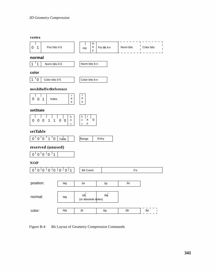
3D Geometry Compression
Figure B-4 Bit Layout of Geometry Compression Commands
vertex
normal
0 1
1 1
rep
mbp
color
1 0
Pos bits 0-5 Pos bits 6-n Norm bits Color bits
Norm bits 0-5 Norm bits 6-n
Color bits 0-5 Color bits 6-n
meshBufferReference
0 0 Index1rep
rep
setState
0 0 0 1 1
setTable
0 0 0 1 0
reserved (unused)
0 0 0 0 1
NOP
0 0 0 0 0 Bit Count 0’s0 0 1
tag ∆x ∆y ∆zposition:
tag ∆θt ∆φtnormal:
tag ∆r ∆g ∆bcolor: ∆α
(or absolute index)
bnv
bcv
cap
Table Range Entry
^ ^
0 0 0
341

Java 3D API Specification—Version 1.0 August 1, 1997
342
y
bit
and
tryl if
t, and if
Thee
bit ae
B.12 Geometry Decompression Command Bit DetailsThe following subsections describe the bit details of several of the geometrdecompression commands, and much of their associated semantics.
B.12.1 NOP
The variable length no-operation command has an eight bit op code, a fivecount field, and a 0 to 31 bit field of zeros.
The total length of the variable length no-operation command is between 1344 bits.
The variable length no-operation command’s primary use is to align geomedecompression commands to word boundaries, when desired. This is usefuone wishes to “patch” a decompression instruction in the middle of a streamwithout having to bit-align the patch.
B.12.2 setState
The setState command has a seven bit op-code, three bits of state to be sea spare, for a total length of 11 bits. The first and second state bits indicatenormals and/or colors will be bundled with vertex commands, respectively. third state bit indicates if colors will contain an alpha value, in addition to thstandard rgb. The final state bit is unused, and reserved for future use.
B.12.3 setTable
The setTable command has a five bit op code, a two bit table field, a sevenaddress/range field, a four bit data length field, an absolute/relative bit, andfour bit up-shift field. The total instruction length is fixed at 23 bits. The tabl
NOP
0 0 0 0 0 Bit Count 0-31 0’s0 0 1
setState
0 0 0 1 1bnv
bcv
cap
0 0
setTable
0 0 0 1 0 Table Data LengthAddress/Range A/R Up-shift

3D Geometry Compression
e; the
ate is
le are
riesrgth of
ny)
is tagns off the
ion.read-th
sitions
ugh
and address/range field specify which decompression table entries to updatremaining fields comprise the value to update the table entries to.
The two-bit table specifies which of the three decompression tables this updtargeted for:
The seven-bit address/range field specifies which entries in the specified tabto be set to the values in the following fields.
The idea is that table settings are made in aligned power of two ranges; theposition of the first ‘1’ bit in the address/range field indicates how many entare to be consecutively set; the remaining bits after the first ‘1’ are the uppeaddress bits of the base of the table entries to be set. This also sets the lenthe “tag” that this entry defines as equal to the number of address bits (if aafter the first ‘1’ bit.
The data length specifies how large the delta values to be associated with thare; a data length of 12 implies that the upper 4 bits are to be sign extensiothe incoming delta value. Note that the data length describes not the length odelta value coming in, but the final position of the delta value for reconstructIn other words, the data length field is the sum of the actual delta bits to be in plus the up-shift amount. For the position and color tables, the data lengvalue of 1–15 correspond to length of 1–15,but the data length value of 0encodes an actual length of 16, as a length of zero makes no sense for poand colors. For normals, a length of zero is sometimes appropriate, and themaximum length needed is only 7. Thus for normals, the value 0–7 map thro0–7, and 8–15 are not used.
00 Position
01 Color
10 Normal
11 Unused – reserved for future use
Address/range Semantics Implicit taglength
1a5a4a3a2a1a0 set table entry a5a4a3a2a1a0 6
01a5a4a3a2a1 set table entry a5a4a3a2a10 through a5a4a3a2a11 5
001a5a4a3a2 set table entry a5a4a3a200 through a5a4a3a211 4
0001a5a4a3 set table entry a5a4a3000 through a5a4a3111 3
00001a5a4 set table entry a5a40000 through a5a41111 2
000001a5 set table entry a500000 through a511111 1
0000001 set table entry 000000 through 111111 0
343

Java 3D API Specification—Version 1.0 August 1, 1997
344
ese
re tomals,
shf
finehatses are
does
edstill
ioneave
The up-shift value is the number of bit that the delta values described by thtags will be shifted up before being added to the current value.
The absolute/relative flag indicates if this table entry describes values that abe interpreted as an absolute reference or a relative delta. Note that for norabsolute references will have an additional six leading bits describing theabsolute octant and sextant.
B.12.4 meshBufferReference
The meshBufferReference command has a three bit op-code, a four bit mebuffer index field, and a two bit vertex replacement field, for a total length onine bits.
The index specifies which element of the mesh buffer should be used to dethe current vertex. A value of zero indicates to use the most recent vertex thas been pushed into the mesh buffer (before this command). Larger valueindicate successively less recent pushes. Only the most recent sixteen pushaddressable.
The two-bit vertex replacement field has the same triangle semantics as it within the Vertex command:
There is no mesh buffer re-push bit; mesh buffer contents may be referencmultiple times until sixteen newer vertices have been pushed; if a vertex is needed it must be re-sent.
B.12.5 Position Sub-command
The position sub-command can only appear within a geometry decompressvertex command, and always as the first sub-command. The tag field can bbetween zero and six bits in length; all three delta (or absolute) fields will h
0 0 Restart clockwise
0 1 Restart counter-clockwise
1 0 Replace middle
1 1 Replace oldest
meshBufferReference
0 0 Index1rep
rep
tag ∆x ∆y ∆zposition:0-6 1-16 1-16 1-16

3D Geometry Compression
three bits
d of first
any
it-
thatases
n six
54 (or has
d of first
any
are
it in the
n no
the same length, between one and 16 bits, for a range of lengths between and 54 bits. As usual, any sub-command with a total length of less than sixhas trailing zeros added to pad the length to a minimum of six bits.
As usual, the first six bits of the sub-command are actually forwarded aheathe rest of the command. Depending on the length of tag and delta fields, thesix bits might only contain the tag, or the tag and some of the x field bits, orsubset up to the entire sub-command if short enough.
For clarity, because it is by far the most typical case, the three coordinate bfields are labeled∆x ∆y ∆z, though more properly they are x, y, and z fields;their actual interpretation is absolute or relative depending on the setting ofbit in the decompression table entry corresponding to the tag field. In both cthe fields are signed 2’s-complement numbers.
B.12.6 Color Sub-command
The color sub-command can appear within either a geometry decompressiovertex command or color command. The tag field can be between zero andbits in length; all three (or four) delta (or absolute) fields will have the samelength, between one and 16 bits, for a range of lengths between three and 70) bits. As usual, any sub-command with a total length of less than six bitstrailing zeros added to pad the length to a minimum of six bits.
As usual, the first six bits of the sub-command are actually forwarded aheathe rest of the command. Depending on the length of tag and delta fields, thesix bits might only contain the tag, or the tag and some of the r field bits, orsubset up to the entire sub-command if short enough.
For clarity, because it is by far the most typical case, the coordinate bit-fieldslabeled∆r ∆g ∆b (∆α), though more properly they are r, g, and b fields; theiractual interpretation is absolute or relative depending on the setting of that bthe decompression table entry corresponding to the tag field. In both casesfields are signed 2’s-complement numbers.
If the most recent setting of the cap bit by a set state command is zero, theforth (alpha) field will be expected, and mustnot be present. If the cap bit wasset, then the alpha field will be processed andmust be present.
0-6 1-16 1-16 1-16tag ∆r ∆g ∆bcolor: ∆α
1-16
345

Java 3D API Specification—Version 1.0 August 1, 1997
346
itsire is are
siond six
th,
andith ao a
d of first
s, or
the theof a
The rest of the graphics pipeline and frame buffer following the geometrydecompression stage may choose not to use all (up to) 16 bits of colorcomponent information; in this case it is acceptable to truncate the trailing bduring decompression. What the geometry decompression format does requthat color setting of any size up to 16 bits are supported, even if all the bitsnot used.
B.12.7 Normal Sub-command
The normal sub-command can appear within either a geometry decompresvertex command or normal command. The tag field can be between zero anbits in length; the last two delta (or absolute) fields will have the same lengbetween one and seven bits. Six more bits are always present for absolutenormals. The range of sizes for a relative normal can be from six to 20 bits,absolute normal can be from six to 24 bits. (As usual, any sub-command wtotal length of less than six bits has trailing zeros added to pad the length tminimum of six bits.)
As usual, the first six bits of the sub-command are actually forwarded aheathe rest of the command. Depending on the length of tag and delta fields, thesix bits might only contain the tag, or the tag and some of the other field bitany subset up to the entire sub-command if short enough.
A normal sub-command is interpreted as relative or absolute depending oncurrent setting of that bit in the decompression table entry corresponding totag field. Unlike the position and color sub-commands, the number of fields normal command differ between the absolute and relative types.
When relative, after the tag field there are two delta angle fields, both of thesame length, up to seven bits. These two fields are signed 2’s-complement
0-6 0-7 0-7
tag ∆θt ∆φtnormal: (relative) ^ ^
0-6 0-6 0-6
tag θt φtnormal: (absolute) ^ ^sextant octant
3 3
0-6
tagnormal: (special) 1 1 special
4

3D Geometry Compression
xtant
f the, and
bers,
withine ag a
itsire is even
numbers. If after delta addition, the resulting angle is outside the current seor octant, the sextant/octant wrapping rules (described elsewhere) apply.
When absolute, four bit-fields follow the tag. The first is a three-bit (fixedlength) absolute sextant field, indicating which of six sextants of an octant ounit sphere this normal resides in. The second field is also fixed at three bitsindicates which octant of the unit sphere the normal resides in. The last twofields are absolute angles within the sextant, and are unsigned positive numup to six bits in length.
Fourteen special absolute normals are encoded by the unused two settings the three sextant bits. This is indicated by specifying the angle fields to havlength of zero (not present), the first two bits of the sextant field both havinvalue of 1, and the trailing bit after the octant field having a value of 0. Thefourteen special normals are:
The rest of the graphics pipeline and frame buffer following the geometrydecompression stage may choose not to use all (up to) 16 bits of normalcomponent information; in this case it is acceptable to truncate the trailing bduring decompression. What the geometry decompression format does requthat normal setting of any size up to 18-bit absolute normals are supported,if all the decompressed bits are not used.
special nx ny nz comment
0000 1.0 0.0 0.0 +x axis
0010 –1.0 0.0 0.0 –x axis
0100 0.0 1.0 0.0 +y axis
0110 0.0 –1.0 0.0 –y axis
1000 0.0 0.0 1.0 +z axis
1010 0.0 0.0 –1.0 –z axis
0001 +x +y +z
0011 +x +y -z
0101 +x –y +z
0111 +x –y -z
1001 –x +y +z
1011 –x +y -z
1101 –x –y +z
1111 –x –y –z
1 3⁄ 1 3⁄ 1 3⁄1 3⁄ 1 3⁄ 1 3⁄1 3⁄ 1 3⁄ 1 3⁄1 3⁄ 1 3⁄ 1 3⁄1 3⁄ 1 3⁄ 1 3⁄1 3⁄ 1 3⁄ 1 3⁄1 3⁄ 1 3⁄ 1 3⁄1 3⁄ 1 3⁄ 1 3⁄
347

Java 3D API Specification—Version 1.0 August 1, 1997
348
s), a
ettinge
esh
12.7,
e the
B.12.8 vertex
The vertex command has a two-bit op-code, a position sub-command (alwaytwo-bit vertex replacement field, a mesh buffer push bit, and, optionally, anormal sub-command and/or a color command, depending on the current sof the state bundling bits. The two bit vertex replacement field has the samtriangle semantics as it does within the mesh buffer reference command:
The mesh buffer push bit indicates if this vertex should be pushed into the mbuffer so as to be eligible for later re-reference.
The position, normal, and color sub-commands have the semantics asdocumented in their individual sections.
B.12.9 normal
The normal command has a two-bit op-code, and a normal sub-command.
The normal sub-command has the semantics as documented in Section B.“Normal Sub-command.”
If a normal command is present immediately before a mesh buffer referenccommand, then the new normal value overrides the normal data present inmesh buffer for that particular mesh buffer reference.
0 0 Restart clockwise
0 1 Restart counter-clockwise
1 0 Replace middle
1 1 Replace oldest
vertex
0 1 rep
mbp
Pos bits 0-5 Pos bits 6-n Norm bits Color bits
normal
1 1 Norm bits 0-5 Norm bits 6-n
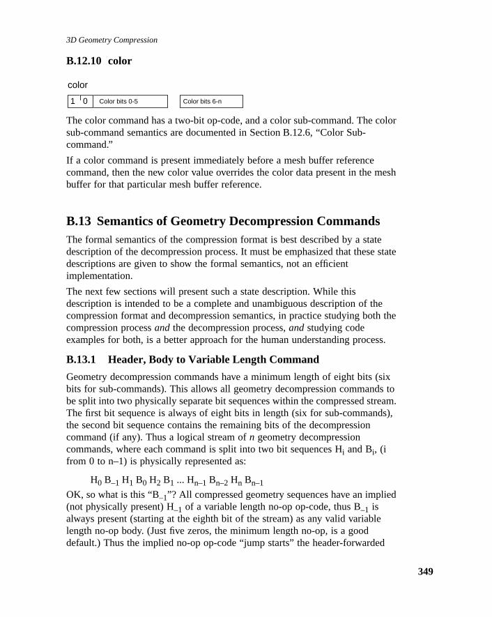
3D Geometry Compression
color
mesh
tee state
eh the
ss.
sixs toeam.s),
ied
e
d
B.12.10 color
The color command has a two-bit op-code, and a color sub-command. The sub-command semantics are documented in Section B.12.6, “Color Sub-command.”
If a color command is present immediately before a mesh buffer referencecommand, then the new color value overrides the color data present in the buffer for that particular mesh buffer reference.
B.13 Semantics of Geometry Decompression CommandsThe formal semantics of the compression format is best described by a stadescription of the decompression process. It must be emphasized that thesdescriptions are given to show the formal semantics, not an efficientimplementation.
The next few sections will present such a state description. While thisdescription is intended to be a complete and unambiguous description of thcompression format and decompression semantics, in practice studying botcompression processand the decompression process,and studying codeexamples for both, is a better approach for the human understanding proce
B.13.1 Header, Body to Variable Length Command
Geometry decompression commands have a minimum length of eight bits (bits for sub-commands). This allows all geometry decompression commandbe split into two physically separate bit sequences within the compressed strThe first bit sequence is always of eight bits in length (six for sub-commandthe second bit sequence contains the remaining bits of the decompressioncommand (if any). Thus a logical stream ofn geometry decompressioncommands, where each command is split into two bit sequences Hi and Bi, (ifrom 0 to n–1) is physically represented as:
H0 B–1 H1 B0 H2 B1 ... Hn–1 Bn–2 Hn Bn–1
OK, so what is this “B–1”? All compressed geometry sequences have an impl(not physically present) H–1 of a variable length no-op op-code, thus B–1 isalways present (starting at the eighth bit of the stream) as any valid variabllength no-op body. (Just five zeros, the minimum length no-op, is a gooddefault.) Thus the implied no-op op-code “jump starts” the header-forwarde
color
1 0 Color bits 0-5 Color bits 6-n
349

Java 3D API Specification—Version 1.0 August 1, 1997
350
H
g withded.f
leate
n-
e bits thelf
essed
he
andngth
decompression process. This process is reversed at the end of the stream; n is avariable length no-op op-code, but no body is present, as Bn–1 is the last bits ofthe stream.
This is viable because all compressed geometry streams are presented alona total bit length of their contents, so no explicit end-of-stream marker is neeStreamsmust be rounded up to the nearest full 64-bit word multiple by use oadditional variable length no-ops (within the body of the stream, e.g. theirheaders appear before Hn).
This “header-forwarding” shuffled representation is necessary for hardwaredecompressors to operate efficiently. While this is not an issue for purelysoftware-based decompressor implementations, in order to have one canticformat for both hard and soft decompressors, all decompressors must operonly on the header-forwarded representation; this is the only “official”compression bit-format specified. For a software decompressor, the extra ushuffling adds only slightly to the overall overhead of decompression; forhardware, it is essential.
Thus the first stage in the decompression process is to put the two separatsequences for each command back together. The next paragraph describeflavor of this process, going around the loop approximately one and one-hatimes. The actual process is more accurately described in state machinesemantics.
First the fixed length 8 (or 6) bit header for thenext full command (or sub-command) to be processed is detached from the current head of the comprstream. Next, the variable length body bits for theprevious command (or sub-command) are detached from the compressed stream and combined with talready extracted header forprevious command; theprevious command is nowcomplete and can be processed. Now the fixed length header for the commafter the next is detached from the bit stream, and then finally the variable lebody for the next full command can be detached; thenext command is nowcomplete and can be processed.
/* pseudo code for converting bit-stream into sequences of/* commands */decompress(stream){ previous_header <- no-op while (not_empty(stream)) { current_header <- get_8_bits(stream) previous_body <- gen_n_bits(stream,body_length(previous_header)) process_command(previous_header, previous_body)

3D Geometry Compression
bits
tagshift
isven
previous_header <- current_header }}
One slight complexity: the get_8_bits() only extracts 6 bits of header for thecolor or normal sub-command of a vertex command. It extracts a full eight of header in all other cases.
B.13.2 Variable Length Command to Command
The three decompression tables contain entries for each different numeric describing if the value in the stream is absolute or relative, and length and constants describing how to convert the variable length bit field back into afixed-length value. The fixed-length value for position and color components16 bits in length (sign, unit, 14 fraction), the fields for normal angles are sebits (signed), and three each for sextant and octant (if present).
B.13.3 Delta Position to Positionabsolute_position(x, y, z):
cur_x ← x, cur_y ← y, cur_z ← z
relative_position( ∆x, ∆y, ∆z):cur_x ← cur_x + ∆x, cur_y ← cur_y + ∆y, cur_z ← cur_z + ∆z
B.13.4 Delta Color to Colorabsolute_color(r, g, b {, α}):
cur_r ← r, cur_g ← g, cur_b ← b, {cur_ α ← α }
relative_color( ∆r, ∆g, ∆g {, ∆α}):cur_r ← cur_r + ∆r, cur_g ← cur_g + ∆g, cur_b ← cur_b + ∆b,{cur_ α ← cur_ α + ∆α }
B.13.5 Encoded Delta Normal to Encoded Normal
State: cur_oct, cur_sex, cur_u, cur_v
absolute_normal(oct, sex, u, v):cur_oct ← oct, cur_sex ← sex, cur_u ← u, cur_v ← v,
relative_normal( ∆u, ∆v):
cur_u ← cur_u + ∆u, cur_v ← cur_v + ∆v,if (cur_u < 0)
cur_u ← -cur_u, cur_sex ← flip_u[cur_sex]else if (cur_v < 0)
cur_v ← -cur_v, cur_oct ← cur_oct <xor> flip_v[cur_sex]else if (cur_u + cur_v > 64)
cur_u ← 64 - cur_u, cur_v ← 64 - cur_v,
351

Java 3D API Specification—Version 1.0 August 1, 1997
352
of
d thatcient
nd toal
d the
cur_sex ← flip_uv[cur_sex]
flip_u[6] = { 4, 5, 3, 2, 0, 1 }flip_v[6] = { 2, 4, 1, 1, 2, 4 }flip_uv[6] = { 2, 3, 0, 1, 5, 4 }
B.13.6 Encoded Normal to Rectilinear Normal
nx ← norms[v,u].nx, ny ← norms[v,u].ny, nz ←norms[v,u].nz,if (cur_sex & 4) t ← nx, nx ← nz, nz ← tif (cur_sex & 2) t ← ny, ny ← nz, nz ← tif (cur_sex & 1) t ← nx, nx ← ny, ny ← tif (cur_oct & 1) nz ← -nzif (cur_oct & 2) ny ← -nyif (cur_oct & 4) nx ← -nx
The contents of the norms[] table is exactly specified, and the next revisionthis specification will contain an exact listing of the values.
B.14 Semantics of VerticesThe formal semantics of the vertex processing is best described by a statedescription of the decompression process. Once again it must be emphasizethese state descriptions are given to show the formal semantics, not an effiimplementation.
B.14.1 Command to Vertex
This section describes the state change semantics caused by each commagenerate the next output vertex, prior to assembly into triangles. The internstate consists of the six mode bits, a current normal and current color,normal_overide and color_overide bits, the sixteen mesh buffer vertices, ancurrent mesh index.
normal(n):current_normal ← n, normal_overide ← 1
color(c):current_color ← c, color_overide ← 1
vertex(rep, mbp, p {, n} {, c}):
current_position ← p,

3D Geometry Compression
if (bnv) current_normal ← n,if (bcv) current_color ← c,output_vertex(rep, current_position, current_normal,current_color)if (mbp) mesh_buffer[oldest_mesh_index].position ← pif (mbp && bnv) mesh_buffer[mesh_index].normal ← nif (mbp && bcv) mesh_buffer[mesh_index].color ← cif (mbp) mesh_index ← (mesh_index+1) & 15normal_overide ← 0, color_overide ← 0
mesh buffer reference(rep, i):
current_position ←mesh_buffer[(mesh_index - i - 1) & 15].position
if (bnv && !normal_overide) current_normal ←mesh_buffer[(mesh_index - i - 1) &15].normalif (bcv && !color_overide) current_color ← mesh_buffer[(mesh_index - i - 1) & 15].coloroutput_vertex(rep, current_position, current_normal,current_color)
set state(new_bnv, new_bcv, new_cap, new_tex):
bnv ← new_bnv,bcv ← new_bcv,cap ← new_cap,tex ← new_tex
set table(address, range, entry): ...
passthrough(data): (null)
vnop(length): (null)
B.14.2 Vertex to Intermediate Triangle
This section describes the formal semantics of assembling vertices withreplacement commands into nearly finished triangles: the semantics ofgeneralized triangle strips.
output_vertex(restart clockwise, newv):newest ← newv, number_of_vertices ← 1, ccw = 0
353

Java 3D API Specification—Version 1.0 August 1, 1997
354
ings.nticsles
output_vertex(restart counterclockwise, newv):newest ← newv, number_of_vertices ← 1, ccw = 1
output_vertex(replace_middle, newv):
if (number_of_vertices < 2)midlest ← newest, newest ← newv, number_of_vertices++
else if (number_of_vertices < 3)oldest ← midlest, midlest ← newest, newest ← newv,number_of_vertices++,intermediate_triangle(ccw, oldest, midlest, newest)
else if (number_of_vertices == 3)midlest ← newest, newest ← newv,intermediate_triangle(ccw, oldest, midlest, newest)
output_vertex(replace_oldest, newv):
if (number_of_vertices < 2)midlest ← newest, newest ← newv, number_of_vertices++
else if (number_of_vertices < 3)oldest ← midlest, midlest ← newest, newest ← newv,number_of_vertices++,intermediate_triangle(ccw, oldest, midlest, newest)
else if (number_of_vertices == 3)oldest ← midlest, midlest ← newest, newest ← newv,ccw = 1 - ccw,intermediate_triangle(ccw, oldest, midlest, newest)
B.14.3 Intermediate Triangle to Final Triangle
The final stage is to take into account the current rnt and rct mode bits settThese control the semantics of the normal and color vertex data. The semaof the counterclockwise bit also can be expressed here, thus the final triangcan always be assumed to be front-facing when their vertices appear incounterclockwise order.
intermediate_triangle(ccw, v1, v2, v3):
if (ccw) final_triangle(v1.position, v1.normal, v1.color,
v2.position, v2.normal, v2.color, v3.position, v3.normal, v3.color)
else if (!ccw) final_triangle(v2.position, v2.normal, v2.color,

3D Geometry Compression
etry
ven
h
ical
, theere.
lthentheinging
ox,ox is
v1.position, v1.normal, v1.color, v3.position, v3.normal, v3.color)
B.15 Outline of Geometry ProcessJava 3D only formally defines the geometry compression format and thedecompression semantics. Authoring tools are free to employ whatever geomcompression algorithms they choose, so long as the results adhere to thespecifications described in the previous sections.
However, to further document the semantics of the geometry compressionformat, an overview of one particular geometry compression algorithm is gihere.
B.15.1 Compressing Geometry Data
Group geometry to be compressed into separate rigid objects. Typically sucobjects will be individually culled during rendering, so you should not joinobjects too extensively prior to compression. In optimized systems, thegranularity of object splitting will be computed by an algorithm that takesculling optimization into account.
B.15.2 Convert to Generalized Mesh Format
Once a group of geometry has been identified, it is next converted intogeneralized mesh format. This is a complex step, and a number of topologanalysis based algorithms have been applied to it.
The next step is the quantization of the geometry positions, colors, normalsand/or texture map coordinates. All these quantizations can be varied withingeometry, but for simplicity a single fixed quantization of each is assumed h
B.15.3 Position
Normalize the position data
The containing bounding box for the object is computed. This is the minimabox such that all geometry vertices are contained within it. The vertices are all normalized to be contained within this bounding box by first subtracting xyz location of the bounding box center from the vertex xyz; and then dividall the xyz vertex values by the half length of the longest side of the boundbox. Thus all normalized positions will be within the±1 unit cube. A constantmatrix transform corresponding to an offset to the center of the bounding band an inverse scale by the half length of the longest side of the bounding bcreated as a prolog for the geometry data.
355

Java 3D API Specification—Version 1.0 August 1, 1997
356
n
td
al
malsalduct
Quantize the position data
Assuming that position data is to be quantized to n bits, each vertex positiocomponent should be multiplied by the value of 2n, and then rounded to thenearest integer.
B.15.4 Normals
Normalize the normals
Each normal should be normalized to unit length.
Quantize the xyz components of the normal to 14 bits accuracy
Each normal component should be multiplied by 214, then rounded to the nearesinteger, and then converted back to floating point representation and divideback by 214.
Quantize the xyz components of the normal to 14 bits accuracy
If an xyz component of the normal is negative, invert it, and save the originsign bits as a three-bit octant value:
oct = 0;if(nx < 0.0) oct |= 4, nx = -nxif(ny < 0.0) oct |= 2, ny = -nyif(nz < 0.0) oct |= 1, nz = -nz
Fold the normal to the nx > nz > ny sextant
Check (in exactly the following order):
sex = 0;if (nx < ny) t = nx, nx = ny, ny = t, sex |= 1if (nz < ny) t = ny, ny = nz, nz = t, sex |= 2if (nx < nz) t = nx, nx = nz, nz = t, sex |= 4
Match the nearest quantize normal representation
Take the dot product of the normal with each of the quantized reference norin the table for the specified number of quantized normal bits. That uv normindex for the reference normal that gives the greatest (nearest unity) dot proresult is the new quantized normal representation.
(along with the octant and sextant representation)
Check for special normals
...

3D Geometry Compression
he
. For
de. is
ing
ign
elta
.
ng this
B.15.5 Colors
The colors are assumed to be in a 0.0 to 1.0 representation to begin with.
Quantize the color values
Assuming that color data is to be quantized to n bits, each vertex colorcomponent (r, g, b, and optionallyα) should be multiplied by the value of 2n,and then rounded to the nearest integer.
Texture map coordinates may appear in place of color components within tcompression stream, as controlled by thetex state bit. If 2D texture mapping isdesired, then the uv texture coordinate values take the place of the rg colorcomponents in the compression stream (b is not present).
B.15.6 Collect Delta Code Statistics
Make a pass in generalized mesh order through all vertices in the geometryeach successive pair of vertices, compute the difference between theircomponent values, compute the bit-length of this (signed) difference, andhistogram this bit length. Specifically for each component type:
B.15.7 Position Delta Code Statistics
Compute∆x, ∆y, and∆z. Determine which of these has the greatest magnituCompute the number of bits for this component, including one sign bit. Thisthe length to be histogrammed for positions.
B.15.8 Color Delta Code Statistics
Compute∆r, ∆g, ∆b, and∆α (if present). Determine which of these has thegreatest magnitude. Compute the number of bits for this component, includone sign bit. This is the length to be histogrammed for colors.
B.15.9 Normal Delta Code Statistics
For a given pair of normals, check to see if they have the same octant andsextant. If so, compute∆u and∆v. Determine which of these has the greatestmagnitude. Compute the number of bits for this component, including one sbit. This is the length to be histogrammed for this pair of normals.
If the normals have different sextants and/or octants, check to see if theirsextants share an edge. Depending on what type of edge they share, the dincluding the change in edges is encoded in one of three ways: u +∆u < 0, v +∆v < 0, and u +∆u + v +∆v > 64. Each case is discussed in the paragraphbelow. The sextant numbers are from the binary codes shown in Figure B-5
Sextants 0 and 4, 1 and 5, and 2 and 3 share the u = 0 edge. When crossiboundary,∆u becomes ~u - last_u. This will generate a negative cur_u value
357

Java 3D API Specification—Version 1.0 August 1, 1997
358
look
look
ers the
look
)reer this
when
during decompression, which causes the decompressor to invert cur_u andup the new sextant in a table.
Sextants 0 and 2, 1 and 3, and 4 and 5 share the u + v = 64 edge.∆u becomes64 - u - last_u and∆v becomes 64 - v - last_v. When cur_u + cur_v > 64, thedecompressor sets cur_u = 64 - cur_u and cur_v = 64 - cur_v, and a table up determines the new sextant.
Each sextant shares the v = 0 edge with its corresponding sextant in anothoctant. When in sextants 1 or 5, the normal moves across the x-axis, acrosy-axis for sextants 0 or 4, and across the z-axis for sextants 2 or 3.∆v becomes~v - last_v. The decompressor inverts a negative cur_v and performs a tableup for a mask to exclusive-or with the current octant value.
Otherwise the normals cannot be delta-encoded, and so the second (targetnormal must be represented by an absolute reference to its three octant, thsextant, and 2 n-bit u v addresses. This is the length to be histogrammed fopair of normals.
Figure B-5 Encoding the Six Sextants of Each Octant of a Sphere
B.15.10 Assign Huffman Tags
Encode data into variable bit length decompression commands
One can use an algorithm similar to the one used by the JPEG imagecompression standard. The main differences are how codes are reassigned
001
000
010
011
100
101
x < y
x = y
x > y
x > zx = zx < z
y < z
y = z
y > z
X
Y
Z

3D Geometry Compression
coded
. Thein thefman
mustasing
e the
their lengths exceed the maximum code length and how the data bits are enin the compressed data stream.
The frequencies of the data lengths are used as leaf nodes in a binary treealgorithm used to generate the tree places the less frequent codes deeper tree. After the tree is built, the traversal path to a leaf node becomes its Hufcode and the depth in the tree becomes its code length.
Codes generated with a length greater than six, the maximum code length,be shortened. These nodes are merged with more frequent nodes by increthe number of sign bits included with the smaller data length.
B.15.11 Assemble the Pieces Into a Bitstream
Given the sequence of variable bit length decompression commands, shufflfirst eight (six) bits of each command ahead of its predecessor’s body.
359

Java 3D API Specification—Version 1.0 August 1, 1997
360

A P P E N D I X C
onust
aust
model
ove, doodel
ree-anthe
ase,
andter. In
ofse
View Model ImplementationDetails
AN application programmer writing a 3D graphics program that will deploy a variety of platforms must anticipate the likely end-user environments and mcarefully construct the view transforms to match those characteristics usinglow-level API. This appendix addresses many of the issues an application mface and describes the sophisticated features that Java 3D’s advanced view provides.
C.1 An Overview of the Java 3D View ModelBoth camera-based and Java 3D-based view models allow a programmer tospecify the shape of a view frustum and, under program control, to place, mand re-orient that frustum within the virtual environment. However, how theythis varies enormously. Unlike the camera-based system, the Java 3D view mallows slaving the view frustum’s position and orientation to that of a six-degof-freedom tracking device. By slaving the frustum to the tracker, Java 3D cautomatically modify the view frustum so that the generated images match end-user’s viewpoint exactly.
Java 3D must handle two rather different “head tracking” situations. In one cwe rigidly attach a tracker’sbase, and thus its coordinate frame, to the displayenvironment. This corresponds to placing a tracker base in a fixed position orientation relative to a projection screen within a room, relative to a compudisplay on a desk, or relative to the walls of a multiple wall projection displaythe second case “head tracking” situation, we rigidly attach a tracker’ssensor,not its base, to the display device. This corresponds to rigidly attaching onethat tracker’s sensors to a head-mounted display and placing the tracker basomewhere within the physical environment.
361

Java 3D API Specification—Version 1.0 August 1, 1997
362
htoes,
ntly
a
r
e
room’s
ight,’s as ifoom
r
hase
mera
t thet
C.2 Physical Environments and Their EffectsImagine an application where the end-user sits on a magic carpet. Theapplication flies the user through the virtual environment by controlling thecarpet’s location and orientation within the virtual world. At first glance, it migseem that the application also controls what the end-user will see—and it dbut only superficially.
The following two examples show how end-user environments can significaaffect how an application must construct viewing transforms.
C.2.1 A Head-mounted Example
Imagine that the end-user sees the magic carpet and the virtual world with head-mounted display and head tracker. As the application flies the carpetthrough the virtual world, the user may turn to look to the left, right, or eventowards the rear of the carpet. Because the head-tracker keeps the rendereinformed of the user’s gaze direction, it might not need to draw the scenedirectly in front of the magic carpet. The view that the renderer draws on thhead-mount’s display must match what the end-user would see had theexperience occurred in the real world.
C.2.2 A Room-mounted Example
Imagine a slightly different scenario, where the end-user sits in a darkened in front of a large projection screen. The application still controls the carpetflight path; however, the position and orientation of the user’s head barelyinfluences the image drawn on the projection screen. If a user looks left or rthen he or she only sees the darkened room. The screen does not move. Itthe screen represents the magic carpet’s “front window” and the darkened rrepresents the “dark interior” of the carpet.
By adding a left and right screen, we give the magic carpet rider a morecomplete view of the virtual world surrounding the carpet. Now our end-usesees the view to the left or right of the magic carpet by turning left or right.
C.2.3 Impact of Head Position and Orientation On the Camera
In the head-mounted example, the user’s head position and orientationsignificantly impacts a camera model’s camera position and orientation but hardly any affect on the projection matrix. In the room-mounted example, thuser’s head position and orientation contributes little to a camera model’s caposition and orientation; however, it does affect the projection matrix.
From a camera-based perspective, the application developer must construccamera’s position and orientation by combining the virtual-world componen

View Model Implementation Details
ate
g onhead-
temtemsal
stem
thetem
(the position and orientation of the magic carpet) and the physical-worldcomponent (the user’s instantaneous head position and orientation).
Java 3D’s view model incorporates the appropriate abstractions to compensautomatically for such variability in end-user hardware environments.
C.3 The Coordinate SystemsThe basic view model consists of eight or nine coordinate systems, dependinwhether the end-user environment consists of a room-mounted display or a mounted display. First, we define the coordinate systems used in a room-mounted display environment. Next we define the added coordinate systemintroduced when using a head-mounted display system.
C.3.1 Room-mounted Coordinate Systems
The room-mounted coordinate system divides into the virtual coordinate sysand the physical coordinate system. Figure C-1 shows these coordinate sysgraphically. The coordinate systems within the grayed area exist in the virtuworld; those outside exist in the physical world. Note that the coexistencecoordinate system exists in both worlds.
Figure C-1 Display Rigidly Attached to Tracker Base
C.3.1.1 The Virtual Coordinate Systems
The Virtual World Coordinate System
The virtual world coordinate system encapsulates the unified coordinate syfor all scene graph objects in the virtual environment. For a given View, thevirtual world coordinate system is defined by the Locale object that containsViewPlatform object attached to the View. It is a right-handed coordinate syswith x to the right, y up, and z towards the viewer.
head headtracker trackerbase other trackers
imageplate coexistencelcc
rcc
Fishtank Mode
virtual
viewplatform vworld
363

Java 3D API Specification—Version 1.0 August 1, 1997
364
of
tedcal
the
ealrld
heva 3D
rame
te at
XY
fined
The ViewPlatform Coordinate System
The ViewPlatform coordinate system is the local coordinate system of theViewPlatform leaf node that the View is attached to.
The Coexistence Coordinate System
A primary implicit goal of any view model is to map a specified local portionthe Physical World into a specified portion of the Virtual World. Onceestablished, one can legitimately ask where the user’s head or hand is locawithin the Virtual World, or where a virtual object is located in the local PhysiWorld. In this way the physical user can interact with objects inhabiting theVirtual World, and vice-versa. To establish this mapping, Java 3D defines aspecial coordinate system, calledCoexistence coordinates, that isdefined to existin both the Physical World and the Virtual World.
The coexistence coordinate system exists half in the virtual world and half inphysical world. The two transforms that go from the coexistence coordinatesystem to the virtual world coordinate system and back again contain all thinformation needed to grow or shrink the virtual world relative to the physicworld as well as the information needed to position and orient the virtual worelative to the physical world.
Modifying the transform that maps the coexistence-coordinate system into tvirtual world coordinate-system changes what the end user can see. The Jaapplication programmer moves the end-user within the virtual world bymodifying this transform.
C.3.1.2 The Physical Coordinate Systems
The Head Coordinate System
The head coordinate system allows an application to import its user’s headgeometry. The coordinate system provides a simple consistent coordinate ffor specifying such factors as the location of the eyes and ears.
The Image Plate Coordinate System
The image plate coordinate system corresponds with the physical coordinasystem of the image generator. The image plate is defined to have its originthe lower left-hand corner of the display area and to lie in the display area’splane. Note that imageplate is a different coordinate system than eitherleftimageplate or rightimageplate. These last two coordinate systems are dein head-mounted environments only (see Section C.3.2, “Head-MountedCoordinate Systems”).

View Model Implementation Details
mystem
ithtiveld to
msstems
t in bothoom-
ate
theandwer. there
The Headtracker Coordinate System
The headtracker coordinate system corresponds to the six-degree-of-freedotracker’s sensor attached to the user’s head. The headtracker’s coordinate sdescribes the user’s instantaneous head position.
The Trackerbase Coordinate System
The trackerbase coordinate system corresponds to the emitter associated wabsolute position-orientation trackers. For those trackers that generate relaposition-orientation information, this coordinate system is that tracker’s initiaposition and orientation. In general, this coordinate system is rigidly attachethe physical world.
C.3.2 Head-Mounted Coordinate Systems
Head-mounted coordinate systems divide the same virtual coordinate systeand the physical coordinate systems. Figure C-2 shows these coordinate sygraphically. As with the room-mounted coordinate systems, the coordinatesystems within the grayed area exist in the virtual world; those outside existhe physical world. Once again, the coexistence coordinate system exists inworlds. The arrangement of the coordinate system differs from those for a rmounted display environment. The head-mounted version of Java 3D’scoordinate system differs in another way. It includes two imageplate coordinsystems, one for each of an end-user’s eyes.
The Leftimageplate and Rightimageplate Coordinate Systems
The leftimageplate and rightimageplate coordinate systems correspond withphysical coordinate system of the image generator associated with the left right eye respectively. The image plate is defined as having its origin at the loleft-hand corner of the display area and lying in the display area’s XY planeNote that the left image plate’s XY plane does not necessarily lie parallel toright image plate’s XY plane. Note that leftimageplate and rightimageplate adifferent coordinate systems than the room-mounted display environment’simageplate coordinate system.
365

Java 3D API Specification—Version 1.0 August 1, 1997
366
ees
scenetion
f ad in
ainededcts,
ost
of six-
Figure C-2 Display Rigidly Attached to the Head Tracker (Sensor)
C.4 The ViewPlatform ObjectThe ViewPlatform object is a leaf object within the Java 3D scene graph. ThViewPlatform object is the only portion of Java 3D’s viewing model that residas a node within the scene graph. Changes to transform group nodes in thegraph hierarchy above a particular ViewPlatform object move the view’s locaand orientation within the Virtual World (see Section 8.4, “ViewPlatform—APlace In the Virtual World”). The ViewPlatform object also contains aViewAttachPolicy and an ActivationRadius (see Section 5.10, “ViewPlatformNode,” for a complete description of the ViewPlatform API).
C.5 The View ObjectThe View object is the central Java 3D object for coordinating all aspects oviewing situation. All parameters that determine the view transform to be userendering on a collected set of canvases in Java 3D are either directly contwithin the View object, or within objects pointed to by a View object (or pointto by these, etc.). Java 3D supports multiple simultaneously-active View objeeach of which controls its own set of canvases.
The Java 3D View object has several instance variables and methods, but mare calibration variables or user-helping functions.
Methods
public final void setTrackingEnable(boolean flag)public final boolean getTrackingEnable()
These methods set and retrieve a flag specifying whether to enable the usedegree-of-freedom tracking hardware.
lcc
rcc
leftimageplate
rightimageplateheadtracker
head
trackerbase
other trackers
coexistence
viewplatform vworld
virtual
Head-Mounted Display (HMD) Mode

View Model Implementation Details
em. by
atedly
thems.
The
sedion
thents.
thew
ach
public final void getUserHeadToVworld(Transform3D t)
This value stores the transform that takes points in the user-head coordinatsystem and translates them into points in the virtual world coordinate systeThis value is read-only. Java 3D continually generates it, but only if enabledusing thesetUserHeadToVworldEnable method.
public final void setUserHeadToVworldEnable(boolean flag)public final boolean getUserHeadToVworldEnable()
These methods set and retrieve a flag that specifies whether or not to repegenerate the userHeadToVworld transform (initially false).
public String toString()
This method returns a string that contains the values of this View object.
C.5.1 View Policy
The view policy informs Java 3D whether it should generate the view usinghead-tracked system of transforms or the head-mounted system of transforThese policies are attached to the Java 3D View object.
Methods
public final void setViewPolicy(int policy)public final int getViewPolicy()
These two methods set and retrieve the current policy for view computation.policy variable specifies how Java 3D uses its transforms in computing newviewpoints, as follows:
• SCREEN_VIEW specifies that Java 3D should compute new viewpointsusing the sequence of transforms appropriate to non-attached screen-bahead-tracked display environments, such as fishtank VR, multiple projectwalls, and VR-desks. This is the default setting.
• HMD_VIEW specifies that Java 3D should compute new viewpoints usingsequence of transforms appropriate to head-mounted display environmeThis policy is not available in compatibility mode (see Section C.11,“Compatibility Mode”).
C.5.2 Screen Scale Policy
The screen scale policy specifies where the screen scale comes from whenview attach policy is NOMINAL_SCREEN_SCALED (see Section 8.4.3, “VieAttach Policy”). The policy can be one of the following:
• SCALE_EXPLICIT – This flag specifies that the scale used for a view attpolicy of NOMINAL_SCREEN_SCALED is taken from the user-providednominalScreenScale variable.
367

Java 3D API Specification—Version 1.0 August 1, 1997
368
w.
when
ent.ngesyhange
isd
nly.
e3D
that of a
erition
atterd-of-
• SCALE_SCREEN_SIZE – This flag specifies that the scale used for a vieattach policy ofNOMINAL_SCREEN_SCALED is derived from the physical screenThis is the default policy.
public final void setScreenScalePolicy(int policy)public final int getScreenScalePolicy()
These methods set and retrieve the current screen scale policy.
public final void setScreenScale(double scale)public final double getScreenScale()
These methods set and retrieve the screen scale value. This value is used the view attach policy isNOMINAL_SCREEN_SCALED and the screen scale policy isSCALE_EXPLICIT.
C.5.3 Window Eyepoint Policy
The window eyepoint policy comes into effect in a non-head-track environmThe policy tells Java 3D how to construct a new view frustum based on chain the field-of-view and in the Canvas3D’s location on the screen. The policonly comes into effect when the application changes a parameter that can cthe placement of the eyepoint relative to the view frustum.
Constants
public static final int RELATIVE_TO_FIELD_OF_VIEW
This variable tells Java 3D that it should modify the eye-point position so it located at the appropriate place relative to the window to match the specifiefield-of-view. This implies that the view frustum will change whenever theapplication changes the field-of-view. In this mode, the eye position is read-oThis is the default setting.
public static final int RELATIVE_TO_SCREEN
This variable tells Java 3D to interpret the eye’s position relative to the entirscreen. No matter where an end-user moves a window (a Canvas3D), Javacontinues to interpret the eye’s position relative to the screen. This implies the view frustum changes shape whenever an end-user moves the locationwindow on the screen. In this mode, the field-of-view is read-only.
public static final int RELATIVE_TO_WINDOW
This variable specifies that Java 3D should interpret the eye’s positioninformation relative to the window (Canvas3D). No matter where an end-usmoves a window (a Canvas3D), Java 3D continues to interpret the eye’s posrelative to that window. This implies that the frustum remains the same no mwhere the end-user moves the window on the screen. In this mode, the fielview is read-only.

View Model Implementation Details
on-
from
from
fromhis
takes
r’s
Methods
public final int getWindowEyepointPolicy()public final void setWindowEyepointPolicy(int policy)
This variable specifies how Java 3D handles the predefined eye-point in a nhead-tracked application. The variable can contain one of three values:RELATIVE_TO_FIELD_OF_VIEW, RELATIVE_TO_SCREEN, andRELATIVE_TO_WINDOW. The default value isRELATIVE_TO_FIELD_OF_VIEW.
C.5.4 Monoscopic View Policy
This policy specifies how Java 3D generates a monoscopic view.
Constants
public final static int LEFT_EYE_VIEW
Specifies that the monoscopic view generated should be the view as seen the left eye.
public final static int RIGHT_EYE_VIEW
Specifies that the monoscopic view generated should be the view as seen the right eye.
public final static int CYCLOPEAN_EYE_VIEW
Specifies that the monoscopic view generated should be the view as seen the “center eye,” the fictional eye half-way between the left and right eyes. Tis the default setting.
Methods
public final void setMonoscopicViewPolicy(int policy)public final int getMonoscopicViewPolicy()
These methods set and return the monoscopic view policy, respectively.I
C.5.5 Sensors and Their Location In the Virtual Worldpublic final void getSensorToVworld(Sensor sensor, Transform3D t)public final void getSensorHotSpotInVworld(Sensor sensor,
Point3d position)public final void getSensorHotSpotInVworld(Sensor sensor,
Point3f position)
The first method takes the sensor’s last reading and generates a matrix thatpoints in that sensor’s local coordinate system and produces correspondingpoints in virtual space. The next two methods transform the specified sensolast hotspot location in the equivalent location in virtual space.
369

Java 3D API Specification—Version 1.0 August 1, 1997
370
orlay a
C.6 The Screen3D ObjectA Screen3D object represents one independent display device. The mostcommon environment for a Java 3D application is a desktop computer with without a head tracker. Figure C-3 shows a scene graph fragment for a dispenvironment designed for such an end-user environment. Figure C-4 showsdisplay environment that matches the scene graph fragment in Figure C-3.
Figure C-3 A Portion of a Scene Graph Containing a Single Screen3D Object
VPView Canvas3D Screen3D
PhysicalBody
PhysicalEnvironment
TGTransformGroup
ViewPlatform

View Model Implementation Details
ws ae
Figure C-4 A Single Screen Display Environment
A multiple projection wall display presents a more exotic environment. Suchenvironments have multiple screens, typically three or more. Figure C-5 shoscene graph fragment representing such a system and Figure C-6 shows thcorresponding display environment.
371

Java 3D API Specification—Version 1.0 August 1, 1997
372
nd
8.8,ramthodsters.
Figure C-5 A Portion of a Scene Graph Containing Three Screen3D Objects
Figure C-6 A Three Screen Display Environment
A multiple screen environment requires more care during the initialization acalibration phase. Java 3D must know how the Screen3D’s are placed withrespect to one another, the tracking device, and the physical portion of thecoexistence coordinate system.
C.6.1 Screen3D Calibration Parameters
The Screen3D object is the 3D version of AWT’s screen object (see Section“The Screen3D Object”). To use a Java 3D system, someone or some progmust calibrate the Screen3D object with the coexistence volume. These meallow that person or program to inform Java 3D of those calibration parame
VPView Canvas3D Screen3D
PhysicalBody
PhysicalEnvironment
TGTransformGroup
ViewPlatform
Canvas3D Screen3D
Canvas3D Screen3D

View Model Implementation Details
n
t inalueshead-the
nate
used
-plateking
latetion a
ye
Measured Parameters
These calibration parameters are set once, typically by a browser, calibratioprogram, system administrator, or system calibrator; not by an applet.
public final void setPhysicalScreenWidth(double width)public final void setPhysicalScreenHeight(double height)
These methods store the screen’s (image plate’s) physical width and heighmeters. The system administrator or system calibrator must provide these vby measuring the display’s active image width and height. In the case of a mounted display, this should be the display’s apparent width and height at focal plane.
C.6.2 Accessing and Changing Head Tracker Coordinatespublic void setTrackerBaseToImagePlate(Transform3D t)public void getTrackerBaseToImagePlate(Transform3D t)
This value stores the tracker-base coordinate system to image-plate coordisystem transform. If head tracking is enabled, this transform is a calibrationconstant. If head tracking is not enabled, this transform is not used. This is only in SCREEN_VIEW mode. User’s must recalibrate whenever the imageplatemoves relative to the tracker.
public void setHeadTrackerToLeftImagePlate(Transform3D t)public void getHeadTrackerToLeftImagePlate(Transform3D t)public void setHeadTrackerToRightImagePlate(Transform3D t)public void getHeadTrackerToRightImagePlate(Transform3D t)
These method get and set the head-tracker coordinate system to left imageand right image plate coordinate system transform respectively. If head tracis enabled, this transform is a calibration constant. If head tracking is notenabled, this transform is not used. This is used only inHMD_VIEW mode.
C.7 The Canvas3D ObjectJava 3D provides special support for those applications that wish to manipuan eye position even in a non-head-tracked display environment. One situawhere such a facility proves useful is an application that wishes to generatevery high-resolution image composed of lower-resolution tiled images. Theapplication must generate each tiled component of the final image from acommon eye position with respect to the composite image but a different eposition from the perspective of each individual tiled element.
373

Java 3D API Specification—Version 1.0 August 1, 1997
374
ye’sItage
nd the. In
s as a
ge-
es ineadn in
nter Thethree
C.7.1 Scene Antialiasingpublic final boolean getSceneAntialiasingAvailable()
This method returns a status flag indicating whether scene antialiasing isavailable.
C.7.2 Accessing and Modifying An Eye’s Image-plate Position
A Canvas3D object provides sophisticated applications with access to the eposition information in head-tracked, room-mounted runtime environments. also allows applications to manipulate the position of an eye relative to an implate in non-head-tracked runtime environments.
public void setLeftEyeInImagePlate(Point3d position)public void getLeftEyeInImagePlate(Point3d position)public void setRightEyeInImagePlate(Point3d position)public void getRightEyeInImagePlate(Point3d position)
These values determine eye placement when a head tracker is not in use aapplication is directly controlling the eye position in image-plate coordinateshead-tracked mode or when thewindowEyePointPolicy isRELATIVE_TO_FIELD_OF_VIEW, this value is derived from other values and isread-only. In head-tracked mode, Java 3D repetitively generates these valuefunction of the current head-position.
public final void getPixelLocationInImagePlate(int x, int y,Point3d position)
This method computes the position of the specified AWT pixel value in imaplate coordinates and copies that value into the object provided.
public final void setLeftManualEyeInImagePlate(Point3d position)public final void setRightManualEyeInImagePlate(Point3d position)public final void getLeftManualEyeInImagePlate(Point3d position)public final void getRightManualEyeInImagePlate(Point3d position)
These methods set and retrieve the position of the manual left and right eyimage plate coordinates. These values determine eye placement when a htracker is not in use and the application is directly controlling the eye positioimage plane coordinates. In head-tracked mode or when thewindowEyePointPolicy isRELATIVE_TO_FIELD_OF_VIEW, this value is ignored.When the windowEyepointPolicy isRELATIVE_TO_WINDOW only the Z value isused.
public final void getLeftEyeInImagePlate(Point3d position)public final void getRightEyeInImagePlate(Point3d position)public final void getCenterEyeInImagePlate(Point3d position)
These methods retrieve the actual position of the left eye, right eye, and ceeye in image-plate coordinates and copy that value into the object provided.center eye s the fictional eye half-way between the left and right eye. These
View Model Implementation Details
, in
dy’seiro that
tent thus
e
the
and
values are a function of thewindowEyepointPolicy , the tracking enable flag,and the manual left, right, and center eye positions.
public final void getVworldToImagePlate(Transform3D t)
This method retrieves the current virtual world coordinates to ImagePlatecoordinates transform and places it into the specified object.
public final void getImagePlateToVworld(Transform3D t)
This method retrieves the current ImagePlate coordinates to virtual worldcoordinates transform and places it into the specified object.
C.7.3 Canvas Width and Heightpublic final double getPhysicalWidth()public final double getPhysicalHeight()
These methods retrieve the physical width and height of this canvas windowmeters.
C.8 The PhysicalBody ObjectThe PhysicalBody object contains information concerning the end-user’s bophysical characteristics. The head parameters allow end-users to specify thown head’s characteristics and thus to customize any Java 3D application sit conforms to their unique geometry. The PhysicalBody object defines headparameters in the head coordinate system. It provides a simple and consiscoordinate frame for specifying such factors as the location of the eyes andthe interpupilary distance.
The Head Coordinate System
The head coordinate system has its origin on the head’s bilateral plane ofsymmetry, roughly half way between the left and right eyes. The origin of thhead coordinate system is known as thecenter eye. The positive X-axis extendsto the right. The positive Y axis extends up. The positive Z axis extends intoskull. Values are in meters.
Constructors
public PhysicalBody()
Constructs a default user PhysicalBody object with the following default eye ear positions:
Left eye: –0.033, 0.0, 0.0Right eye: 0.033, 0.0, 0.0Left ear: –0.080, -0.030, 0.095Right ear: 0.080, -0.030, 0.095
375

Java 3D API Specification—Version 1.0 August 1, 1997
376
ear
ser’s
nd
from
fault
of thee
bject.
alut
public PhysicalBody(Point3d leftEyePosition,Point3d rightEyePosition)
public PhysicalBody(Point3d leftEyePosition,Point3d rightEyePosition, Point3d leftEarPosition,Point3d rightEarPosition)
These methods construct a PhysicalBody object with the specified eye andpositions.
Methods
public void getLeftEyePosition(Point3d position)public void setLeftEyePosition(Point3d position)public void getRightEyePosition(Point3d position)public void setRightEyePosition(Point3d position)
These methods set and retrieve the position of the center of rotation of a uleft and right eyes in head coordinates.
public void getLeftEarPosition(Point3d position)public void setLeftEarPosition(Point3d position)public void getRightEarPosition(Point3d position)public void setRightEarPosition(Point3d position)
These methods set and retrieve the position of the user head object’s left aright ear positions in head coordinates.
public double getNominalEyeHeightFromGround()public void setNominalEyeHeightFromGround(double height)
These methods set and retrieve the user’s nominal eye height as measuredthe ground to the center eye in the default posture. In a standard computermonitor environment, the default posture would be seated. In a multiple-projection display room environment, or a head-tracked environment, the deposture would be standing.
public void getNominalEyeOffsetFromNominalScreen(double offset)public void setNominalEyeOffsetFromNominalScreen(double offset)
These methods set and retrieve the offset from the center eye to the center display screen. This offset distance allows an “Over the shoulder” view of thscene as seen by the end-user.
public String toString()
This method returns a string that contains the values of this PhysicalBody o
C.9 The PhysicalEnvironment ObjectThe PhysicalEnvironment object contains information about the local PhysicWorld of the end-user’s physical environment. This includes information aboaudio output devices and tracking sensor hardware, if present.

View Model Implementation Details
ct.
or
icestickfors
ene issingandated
to
within
ent
Constructors
public PhysicalEnvironment()public PhysicalEnvironment(int sensorCount)
These constructors construct and initialize a new physical environment objeThe first constructor constructs a new physical environment object with thefollowing default sensor and audio fields, and as array of sensorCount sensobjects.
Audio device count: 1Audio devices: nullInput sensor count: 10Tracking available: falseInput Sensors: null
The sensor information provides real-time access to “continuous” input devsuch as joysticks and trackers. It also contains two-degree-of-freedom joysand six-degree-of-freedom tracker information. See Section 9.2, “Sensors,” more information. Java 3D uses Java AWT’s event model for non-continuouinput devices such as keyboards—see Chapter 9, “Input Devices.”
Audio device information associated with the PhysicalEnvironment allows thapplication a mechanism to choose a particular audio device (if more than oavailable) and explicitly set the type of audio playback for sound rendered uthis device. See Chapter 11, “Audio Devices,” for more details on the fields methods that set and initialize the device driver and output playback associwith the audio device.
Methods
The PhysicalEnvironment object specifies the following methods pertaining audio output devices and input sensors.
public void setAudioDevice(AudioDevice device)
This method selects the specified AudioDevice object as the device throughwhich audio rendering for this PhysicalEnvironment will be performed.
public AudioDevice getAudioDevice()
This retrieves the specified AudioDevice object.
public void setSensorCount(int count)public int getSensorCount()
These methods set and retrieve the count of the number of sensors stored the PhysicalEnvironment object. It defaults to a small number of sensors. Itshould be set to the number of sensors available in the end-user’s environmbefore initializing the Java 3D API.
377

Java 3D API Specification—Version 1.0 August 1, 1997
378
t. Ifh
able.
ed.
hand.
he
tion of
public void setCoexistenceToTrackerBase(Transform3D t)public void getCoexistenceToTrackerBase(Transform3D t)
Sets the coexistence coordinate system to tracker-base coordinate systemtransform. If head tracking is enabled, this transform is a calibration constanhead tracking is not enabled, this transform is not used. This is used in botSCREEN_VIEW andHMD_VIEW modes.
public boolean getTrackingAvailable()
This method returns a status flag indicating whether or not tracking is avail
public void setSensor(int index, Sensor sensor)public Sensor getSensor(int index)
The first method sets the sensor specified by the index to the sensor providThe second method retrieves the specified sensor.
public void setDominantHandIndex(int index)public int getDominantHandIndex()
These methods set and retrieve the index of the dominant hand.
public void setNonDominantHandIndex(int index)public int getNonDominantHandIndex()
These methods set and retrieve the index of the non-dominant hand.
public void setHeadIndex(int index)public int getHeadIndex()public void setRightHandIndex(int index)public int getRightHandIndex()public void setLeftHandIndex(int index)public int getLeftHandIndex()
These methods set and retrieve the index of the head, right hand, and left The index parameter refers to the sensor index.
Physical Coexistence Policy
The setCoexistenceCenterInPworldPolicy andgetCoexistenceCenterInPworldPolicy methods in the PhysicalEnvironmentobject store and retrieve the parameter that specifies how Java 3D places tuser’s eye-point as a function of current head-position during the calibrationprocess. Java 3D permits one of three values:NOMINAL_HEAD, NOMINAL_FEET, orNOMINAL_SCREEN.
public int getCoexistenceCenterInPworldPolicy()public void setCoexistenceCenterInPworldPolicy(int policy)
This variable specifies how Java 3D will place the user’s eye-point as a funcof current head-position during the calibration process. Java 3D permits onethree values:NOMINAL_HEAD, NOMINAL_FEET, or NOMINAL_SCREEN. Note:NOMINAL_SCREEN_SCALED is not allowed for this policy.

View Model Implementation Details
for aibe
kingribe
heiew
ationeye’she
ato
head
lsodn and
otmovens
ire and
e inces
C.10 Viewing in Head Tracked EnvironmentsSection 8.5, “Generating a View,” describes how Java 3D generates a view standard flat screen display with no head tracking. In this section, we descrhow Java 3D generates a view in a room-mounted, head-tracked displayenvironment—either a computer monitor with shutter glasses and head tracor a multiple-wall display with head-tracked shutter glasses. Finally, we deschow Java 3D generates view matrices in a head-mounted and head-trackeddisplay environment.
C.10.1 A Room-mounted Display (Computer Monitor) With Head-Tracking
When head-tracking combines with a room-mounted display environment, tViewPlatform’s origin and orientation serves as a base for constructing the vmatrices. Additionally, Java 3D uses the end-user’s head position and orientto compute where an end-user’s eyes are located in physical space. Each position serves to offset the corresponding virtual eye’s position relative to tViewPlatform’s origin. Each eye’s position also serves to specify that eye’sfrustum since the eye’s position relative to a Screen3D uniquely specifies theye’s view frustum. Note that Java 3D will access the PhysicalBody object tobtain information describing the user’s interpupilary distance and trackinghardware, values it needs to compute the end-user’s eye positions from theposition information.
C.10.2 A Head-Mounted Display, Head-Tracking
In a head-mounted environment, the ViewPlatform’s origin and orientation aserves as a base for constructing view matrices. And, as in the head-trackeroom-mounted environment, Java 3D also uses the end-user’s head positioorientation to further modify the ViewPlatform’s position and orientation. In ahead-tracked, head-mounted display environment, an end-user’s eyes do nmove relative to their respective display screens, rather the display screens relative to the virtual environment. A rotation of the head by an end-user caradically affect the final view’s orientation. In this situation, Java 3D combinethe position and orientation from the ViewPlatform with the position andorientation from the head-tracker to form the view matrix. The view frustumhowever does not change since the user’s eyes do not move relative to therespective display screen so Java 3D can compute the projection matrix onccache the result.
If any of the parameters of a View object are updated, this will effect a changthe implicit viewing transform (and thus image) of any Canvas3D that referenthat view object.
379

Java 3D API Specification—Version 1.0 August 1, 1997
380
the
rs ofns
d,ing
in
by
s
ons.
rtualiew
temtheion,r.
ecifyde
ew
thgs,
C.11 Compatibility ModeA camera-based view model allows application programmers to think aboutimages displayed on the computer screen as if a virtual camera took thoseimages. Such a view model allows application programmers to position andorient a virtual camera within a virtual scene; to manipulate some parametethe virtual camera’s lens (specify its field-of-view); and to specify the locatioof the near and far clip planes.
Java 3D allows applications to enable compatibility mode, for room-mountenon-head-tracked display environments, or to disable compatibility mode usthe following methods. Camera-based viewing functions are only available compatibility mode.
Methods
public final void setCompatibilityModeEnable(boolean flag)public final boolean getCompatabilityModeEnable()
This flag turns on or off compatibility mode. Compatibility mode is disabled default.
Note: Use of these view-compatibility functions will disable some of Java 3D’view model features, and limit the portability of Java 3D programs. Thesemethods are primarily intended to help jump-start porting of existing applicati
C.11.1 Overview of the Camera-based View Model
The traditional camera-based view model, shown in Figure C-7, places a vicamera inside a geometrically-specified world. The camera “captures” the vfrom its current location, orientation, and perspective. The visualization systhen draws that view on the user’s display device. The application controls view by moving the virtual camera to a new location, by changing its orientatby changing its field-of-view, or by controlling some other camera paramete
The various parameters that users control in a camera-based view-model spthe shape of a viewing volume (known as a frustum because of its truncatepyramidal shape) and locate that frustum within the virtual environment. Threndering pipeline uses the frustum to decide which objects to draw on thedisplay screen. The rendering pipeline does not draw objects outside the vifrustum and it clips (partially draws) objects that intersect the frustum’sboundaries.
Though a view-frustum’s specification may have many items in common withose of a physical camera, such as placement, orientation, and lens settin

View Model Implementation Details
tumlanes.
r tohee toeare
ed
istinglins
gd tothuscts
some frustum parameters have no physical analog. Most noticeable, a frushas two parameters not found on a physical camera: the near and far clip p
The location of the near and far clip planes allow the application programmespecify which objects Java 3D should not draw. Objects too far away from tcurrent eye-point usually do not result in interesting images. Those too closthe eye-point might obscure the interesting objects. By carefully specifying nand far clip planes, an application programmer can control which objects threnderer will not be drawing.
Figure C-7 The Camera-based View Model
From the perspective of the display device, the virtual camera’s image-plancorresponds to the display screen. The camera’s placement, orientation, anfield-of-view determine the shape of the view frustum.
C.11.2 Using the Camera-based View Model
The camera-based view model allows Java 3D to bridge the gap between ex3D code and Java 3D’s view model. By using the camera-based view-modefunctions, a programmer retains the familiarity of the older view model but gasome of the flexibility afforded by Java 3D’s new view model.
The traditional camera-based view model is supported in Java 3D by helpinmethods in the Transform3D object. These methods were explicitly designeresemble as closely as possible the view functions of older packages, and should be familiar to most 3D programers. The resulting Transform3D objecan be used to set compatibility mode transforms in the View object.
C.11.2.1 Creating a Viewing Matrix
The Transform3D object provides the following method to create a viewingmatrix.
Near clip plane
Far clip plane
View frustum
381

Java 3D API Specification—Version 1.0 August 1, 1997
382
g
hin
nge and
ye
m (as
:
e
public void lookAt(Point3d eye, Point3d center, Vector3d up)
This is a utility method that specifies the position and orientation of a viewintransform. It works very similarly to the equivalent function in OpenGL. Theinverse of this transform can be used to control the ViewPlatform object witthe scene graph. Alternatively, this transform can be passed directly to theView’s VpcToEc transform via the compatibility mode viewing functions (seeSection C.11.2.3, “Setting the Viewing Transform”).
C.11.2.2 Creating a Projection Matrix
The Transform3D object provides the following three methods to create aprojection matrix. All three map points from Eye Coordinates (EC) to ClippiCoordinates (CC). Eye Coordinates is defined such that (0, 0, 0) is at the eythe projection plane is atz=-1 .
public void frustum(double left, double right, double bottom,double top, double near, double far)
The frustum method establishes a perspective projection with the eye at theapex of a symmetric view frustum. The transform maps coordinates from ECoordinates (EC) to Clipping Coordinates (CC). The clipping coordinatesgenerated by the resulting transform are in a right-handed coordinate systeare all other coordinate systems in Java 3D).
The arguments define the frustum and its associated perspective projection(left , bottom , -near) and(right , top , -near) specify the point on the nearclipping plane that maps onto the lower-left and upper-right corners of thewindow, respectively. The-far parameter specifies the far clipping plane. SeFigure C-8.
Figure C-8 A Perspective Viewing Frustum
near
far
top
bottomright
left
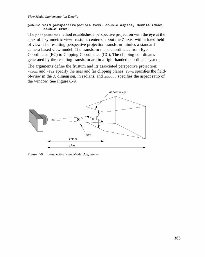
View Model Implementation Details
theeld
m.
:
public void perspective(double fovx, double aspect, double zNear,double zFar)
Theperspective method establishes a perspective projection with the eye atapex of a symmetric view frustum, centered about the Z axis, with a fixed fiof view. The resulting perspective projection transform mimics a standardcamera-based view model. The transform maps coordinates from EyeCoordinates (EC) to Clipping Coordinates (CC). The clipping coordinatesgenerated by the resulting transform are in a right-handed coordinate syste
The arguments define the frustum and its associated perspective projection-near and-far specify the near and far clipping planes;fovx specifies the field-of-view in the X dimension, in radians, andaspect specifies the aspect ratio ofthe window. See Figure C-9.
Figure C-9 Perspective View Model Arguments
zNear
zFar
aspect = x/y
fovx
Θ xy
383

Java 3D API Specification—Version 1.0 August 1, 1997
384
tionps
ded
C)d,
public void ortho(double left, double right, double bottom,double top, double near, double far)
Theortho method establishes a parallel projection. The orthographic projectransform mimics a standard camera-based video model. The transform macoordinates from Eye Coordinates (EC) to Clipping Coordinates (CC). Theclipping coordinates generated by the resulting transform are in a right-hancoordinate system
The arguments define a rectangular box used for projection:(left , bottom ,-near) and(right , top , -near) specify the point on the near clipping planethat maps onto the lower-left and upper-right corners of the window,respectively. The-far parameter specifies the far clipping plane. SeeFigure C-10.
Figure C-10 Orthographic View Model
C.11.2.3 Setting the Viewing Transform
The View object provides the following compatibility-mode methods thatoperate on the viewing transform.
public final void setVpcToEc(Transform3D vpcToEc)public final void getVpcToEc(Transform3D vpcToEc)
This compatibility mode function specifies the ViewPlatform Coordinates (VPto Eye Coordinates (EC) viewing transform. If compatibility mode is disablethis transform is derived from other values and is read-only.
C.11.2.4 Setting the Projection Transform
The View object provides the following compatibility-mode methods thatoperate on the projection transform.
bottom
near far
left
top
rightToward theviewpoint
View volume

View Model Implementation Details
dateswn.
public final void setLeftProjection(Transform3D projection)public final void getLeftProjection(Transform3D projection)public final void setRightProjection(Transform3D projection)public final void getRightProjection(Transform3D projection)
These compatibility mode functions specify a viewing frustum for the left anright eye that transforms points in Eye Coordinates (EC) to Clipping Coordin(CC). If compatibility mode is disabled, a ResrictedAccessException is throIn monoscopic mode, only the left eye projection matrix is used.
385

Java 3D API Specification—Version 1.0 August 1, 1997
386

A P P E N D I X D
rrorsh as
riousf
eionss.
de,
ormnly
tain
a
Exceptions
THE Java 3D API uses the standard Java exception model for handling eor exceptional conditions. In addition to using existing exception classes, sucArrayIndexOutOfBoundsException andIllegalArgumentException , Java 3Ddefines several new runtime exceptions. These exceptions are thrown by vaJava 3D methods or by the Java 3D renderer to indicate an error condition osome kind.
The exceptions defined by Java 3D, as part of thejavax.media.j3d package, aredescribed in the following sections. They all extendRuntimeException and, assuch, need not be declared in thethrows clause of methods that might cause thexception to be thrown. This appendix is not an exhaustive list of all exceptexpected for Java 3D. Additional exceptions will be added as the need arise
D.1 BadTransformExceptionIndicates an attempt to use a Tranform3D object that is inappropriate for theobject in which it is being used. For example:
• Transforms that are used in the scene graph, within a TransformGroup nomust be affine. They may optionally contain a non-uniform scale and/or ashear, subject to other listed restrictions.
• All transforms in the TransformGroup nodes above a ViewPlatform objectmust be congruent. This ensures that the Vworld coordinates to ViewPlatfcoordinates transform is angle and length-preserving with no shear and ouniform scale.
• Most viewing transforms other than those in the scene graph can only contranslation and rotation.
• The projection transform is allowed to be non-affine, but it must either be single point perspective projection or a parallel projection.
387
Java 3D API Specification—Version 1.0 August 1, 1997
388
firstring to
ct
firstring to
s is
his
firstring to
or
Constructors
public BadTransformException()public BadTransformException(String str)
These create the exception object that outputs the exception message. Theform uses the default message. The second form specifies the message stbe output.
D.2 CapabilityNotSetExceptionThis exception indicates an access to a live or compiled Scene Graph objewithout the required capability set.
Constructors
public CapabilityNotSetException()public CapabilityNotSetException(String str)
These create the exception object that outputs the exception message. Theform uses the default message. The second form specifies the message stbe output.
D.3 DanglingReferenceExceptionThis exception indicates that during acloneTree call, an updated reference warequested for a node that did not get cloned. This occurs when a sub-graphduplicated viacloneTree and has at least one Leaf node that contains areference to a Node with no corresponding node in the cloned sub-graph. Tresults in two Leaf nodes wanting to share access to the same Node.
If dangling references are to be allowed during the cloneTree call,cloneTree
should be called with theallowDanglingReferences parameter set to true.
Constructors
public DanglingReferenceException()public DanglingReferenceException(String str)
These create the exception object that outputs the exception message. Theform uses the default message. The second form specifies the message stbe output.
D.4 IllegalSharingExceptionThis exception indicates an illegal attempt to share a scene graph object. Fexample, the following are illegal:

Exceptions
ediate
etry
firstring to
dd a
firstring to
thout that
• referencing a shared subgraph in more than one virtual universe
• using the same component object both in the scene graph and in an immmode graphics context
• including an unsupported type of leaf node within a shared subgraph
• referencing a BranchGroup node in more than one of the following ways:n attaching it to a (single) Locale
n adding it as a child of a Group node within the scene graph
n referencing it from a (single) Background leaf node as background geom
Constructors
public IllegalSharingException()public IllegalSharingException(String str)
These create the exception object that outputs the exception message. Theform uses the default message. The second form specifies the message stbe output.
D.5 MultipleParentExceptionThis exception extends IllegalSharingException and indicates an attempt to anode that is already a child of one group node into another group node.
Constructors
public MultipleParentException()public MultipleParentException(String str)
These create the exception object that outputs the exception message. Theform uses the default message. The second form specifies the message stbe output.
D.6 RestrictedAccessExceptionThis exception indicates an attempt to access or modify a state variable wipermission to do so. For example, invoking a set method for a state variableis currently read-only.
389

Java 3D API Specification—Version 1.0 August 1, 1997
390
firstring to
ablend, as
cycle
firstring to
firstring to
Constructors
public RestrictedAccessException()public RestrictedAccessException(String str)
These create the exception object that outputs the exception message. Theform uses the default message. The second form specifies the message stbe output.
D.7 SceneGraphCycleExceptionThis exception indicates that one of the live scene graphs attached to a viewLocale has a cycle in it. Java 3D scene graphs are directed acyclic graphs asuch, do not permit cycles. This exception is either thrown by the Java 3Drenderer at scene graph traversal time or when a scene graph containing ais made live (added as a descendant of a Locale object).
Constructors
public SceneGraphCycleException()public SceneGraphCycleException(String str)
These create the exception object that outputs the exception message. Theform uses the default message. The second form specifies the message stbe output.
D.8 SingularMatrixExceptionThis exception, in thejava.vecmath package, indicates that the inverse of amatrix cannot be computed.
Constructors
public SingularMatrixException()public SingularMatrixException(String str)
These create the exception object that outputs the exception message. Theform uses the default message. The second form specifies the message stbe output.
D.9 SoundExceptionThis exception indicates a problem in loading or playing a sound sample.

Exceptions
firstring to
Constructors
public SoundException()public SoundException(String str)
These create the exception object that outputs the exception message. Theform uses the default message. The second form specifies the message stbe output.
391

Java 3D API Specification—Version 1.0 August 1, 1997
392

A P P E N D I X E
d
Equations
THIS appendix contains the Java 3D equations for fog, lighting, sound, antexture mapping. Many of the equations use the following symbols:
E.1 Fog EquationsTo be supplied.
E.2 Lighting EquationsThe ideal lighting equation is as follows:
(Eq1)
(Eq2)
(Eq3)
Note: If (L i • N) ≤ 0, then diffi and speci are set to 0.
(Eq4)
⋅ Multiplication
• Function operator for Sound Equations,Dot product for all other Equations
Me Ma+ Lc i( ) atten i spot i dif f i spec i+( )⋅ ⋅( )i
Numlt
∑+i
Numamb
∑⋅
dif f i L i N•( ) Lc i Md⋅ ⋅=
spec i Si N•( )shinLc i Ms⋅ ⋅=
atten i 1 Kci K l i d i Kqi d i2⋅+⋅+( )⁄=
393

Java 3D API Specification—Version 1.0 August 1, 1997
394
e,
s are
ror
Note: For directional lights, atteni is set to 1.
(Eq5)
Note: If the vertex is outside the spotlight cone, as defined by the cutoff anglspoti is set to 0. For directional and point lights, spoti is set to 1.
This is a subset of OpenGL in that the Java 3D ambient and directional lightnot attenuated and only ambient lights contribute to ambient lighting.
The parameters used in the lighting equation are as follows:
The per-light values are as follows:
Fallbacks and Approximations
1. An implementation may approximate the specular function using adifferent power function that produces a similar specular highlight. Foexample, the PHIGS+ lighting model specifies that the reflection vect
E = Eye vector
Ma = Material ambient color
Md = Material diffuse color
Me = Material emissive color
Ms = Material specular color
N = Vertex normal
shin = Material shininess
di = Distance from vertex to light
Di = Spotlight direction
expi = Spotlight exponent
Kci = Constant attenuation
Kli = Linear attenuation
Kqi = Quadratic attenuation
Li = Direction from vertex to light
Lci = Light color
Si = Specular half-vector = || (Li + E) ||
spot i max Li– Di⋅( ) 0,( )ex p i=

Equations
ye
an
r mayolor.e
hones
ignal.
ed)and
ls are. This
byDased
(the light vector reflected about the vertex normal) is dotted with the evector, and that this dot product is raised to the specular power. Animplementation that uses such a model should map the shininess intoexponent that most closely matches the affect produced by the idealequation.
2. Implementations that do not have a separate ambient and diffuse colofall back to using an ambient intensity as a percentage of the diffuse cThis ambient intensity should be calculated using the NTSC luminancequation:
I = 0.30 ⋅ Red + 0.59⋅ Green + 0.11⋅ Blue (Eq6)
E.3 Sound EquationsThere are different sets of sound equations, depending on the use of headpor speakers.
E.3.1 Headphone Playback Equations
For each sound source, Java 3D calculates a separate left and right output sEach left and right sound image is made up of the aninteraural intensity and aninteraural delay. The calculation results are a set of direct and indirect (delaysound signals mixed together when sent to the audio playback system left right transducers.
E.3.1.1 Interaural Time Difference (Delay)
For each point and cone sound source node, the left and right output signadelayed based on the location of the sound and the orientation of the headtime difference between these two signals is called theinteraural time difference(ITD). This time delay of a particular sound reaching the far ear is affected the shadow of the listener's head. Java 3D uses an approximation of the ITusing a spherical head model. The interaural path difference is calculated bon the following cases:
1. For sound source “near” parallel sound incidence (Dh > De/2) – SeeFigure E-1:
Ec = |Vc|Ef = Ec + P
where
P = De ⋅ ((α + sinα)/2)
395

Java 3D API Specification—Version 1.0 August 1, 1997
396
irect
Figure E-1 Distance Source Nearly Parallel Sound Incidence
2. For sources close to the head with the signal reaching one ear by a dpath(sinα > (De/2Dh), and thus–1 ≤ De/2Dh≤ 1 (See Figure E-2):
Ec = |Vc|Ef = Ec + P
where
P = De ⋅ [(m + 1/2) ⋅ cosδ + 1/2(α + δ) –sqrt(ms + m + 1/2 – ((m + 1/2)⋅ (De/2Dh)) ) ]
m = (Dh – (De/2))/De
δ = arcsin(De/2Dh)
De Va
Vl
P
Vh
Vr
α

Equations
th ears
Figure E-2 Source Near Head – Signal to One Ear is Indirect
3. For sound source very close to the head so that the signal reaches boby indirect paths around the head (sinα ≤ De/2Dh) – See Figure E-3:
Ec = α + sqrt(Dh2 – (De/2)2)Ef = Ec + P
where
P = De ⋅ α
Figure E-3 Source Very Close to Head – Signals to Both Ears are Indirect
De Va
Vl
Vr
Dh Vh
α
P
De Va
Vh Vl
Vr
α
Dh
α
P
397

Java 3D API Specification—Version 1.0 August 1, 1997
398
theound.
hichnd to
no
The time from the sound source to the closest ear is Ec/S, and the time fromsound source to the farthest ear is Ef/S, where S is the region’s speed of s
If sound is closest to left ear then:
ITDl = Ec/S, andITDr = Ef/S (Eq7)
If sound is closest to right ear then
ITDl = Ef/S, andITDr = Ec/S (Eq8)
The parameters used in the ITD equations are as follows:
E.3.1.2 Interaural Intensity (Gain) Difference
For each active and playing Point and ConeSound source, s, separatecalculations for the left and right signal (based on which ear is closest and wis farthest to the source) are combined with non-spatialized BackgroundSoucreate a stereo sound image.
(Eq9)
Note: For BackgroundSound sources ITD() is an identity function so there isdelay applied to the sample for these sources.
(Eq10)
α = Angle between Vh and Va in radians
De = Distance between ears (interaural distance)
Dh = Distance from interaural center to sound source
Ec = Distance from sound source to ear closest to sound
Ef = Distance from sound source to ear farthest from sound
P = Difference between Paths to right and left ears from source
Va = Vector from center ear forward parallel to Z axis of head coordinates
Vc = Vector from sound source to ear closest to sound
Vf = Vector from sound source to ear farthest from sound
Vh = Vector from center ear to sound source
I t( ) l r,[ ]
G i( ) l r,[ ] F i( ) l r,[ ] ITD i( ) l r,[ ] Sample t( )•[ ]•( )⋅[ ]i
numS
∑maxNumS
---------------------------------------------------------------------------------------------------------------------------------------------------------=
G l r,[ ] Gi Gd Ec Ef,[ ] Ga α( )⋅ ⋅=

Equations
rces
r
d Fthe.
,y,
,)
Note: For BackgroundSound sources Gd() = Ga() = 1.0. For PointSound souGa() = 1.0.
(Eq11)
Note: For BackgroundSound sources Fd() and Fa() are identity functions. FoPointSound sources Fa() is an identity function.
If the Sound source is on the right side of the head, Ec is used for left G ancalculations and Ef is used for right. Conversely, if the Sound source is on left side of the head, Ef is used for left calculations and Ec is used for right
E.3.1.3 Attenuation
For the vector from the sound source position through the listener’s positionintersection points on the spheres, defined by the distance attenuation arradefine both the index k within the distanceAttenuation arrays from whichdistance gain scale factors are acquired, and the distances, d1 = d[k] and d2 =d[k+1] from the sound position to these intersection points.
Figure E-4 ConeSound with a Single Distance Gain Attenuation Array
For the vector from the sound source position through the listener’s positionintersection points on the two ellipses closest to the listener (points A and Bdefine both the index k within the front and back distanceAttenuation arraysfrom which distance gain scale factors are acquired, and the distances, d1 and d2,from the sound position to these intesection points.
F l r,[ ] Fd Ec Ef,[ ] Fa α( )•=
Listener
Vh
C
D
α
B
A
A = (d[k], Gd[k])B = (d[k+1], Gd[k+1])C = (α[k], Ga[k])D = (α[k+1], Ga[k+1])
399

Java 3D API Specification—Version 1.0 August 1, 1997
400
n for
Figure E-5 ConeSound with Two Distance Attenuation Arrays
The equation for the distance gain is:
(Eq12)
Angular Attenuation for both the spherical and elliptical cone sounds isidentical. The angular distances in the attenuation array closest toα is found anddefine the index k into the angular attenuation array elements. The equatiothe angular gain is:
(Eq13)
Listener
Vh
C
D
frontDistanceAttenuation[]
α
backDistanceAttenuation[]
A
B
A = (d1, Gd[k])B = (d2, Gd[k+1])C = (α[k], Ga[k])D = (α[k+1], Ga[k+1])
Gd Gd k[ ]Gd k 1+[ ] Gd k[ ]–( ) d 2 d 1–( )⋅
L d 1–---------------------------------------------------------------------------------
+=
Ga Ga k[ ] Ga k 1+[ ] Ga k[ ]–( ) α k 1+[ ] α k[ ]–( )⋅α α k[ ]–
------------------------------------------------------------------------------------------------------- +=

Equations
ed onth, as
The parameters used in the IID equations are as follows:
E.3.1.4 Doppler Effect Equations
The frequency of sound waves emanating from the source are lowered basthe speed of the source in relation to the listener, and the sound wave lengfollows:
S(f)' = S(f) - [Ds⋅ (Dv/W(f,Dh)] (Eq14)
A, B = DistanceAttenuation pairs containing linear distance and gainscale factor
C,D = AngularAttenuation pairs containing angular distance andgain scale factor
α = Angle between Vh and Va in radians
d = Distance from sound source to left or right ear (either Ec or Ef)
Ec = Distance from sound source to ear closest to sound from theITD equation
Ef = Distance from sound source to ear farthest from sound sourcefrom the ITD equation
Fa = Angular filter from ConeSound definition
Fd = Distance Filter from aural attribute
Ga = Angular Gain attenuation scale factor
Gd = Distance Gain attenuation scale factor
Gi = Initial Gain scale factor
I = Stereo sound image
L = Listener distance from sound source
maxNumS = Maximum number of sound sources for the audio deviceapplication is using for playback
numS = Number of sound sources
sample = Sound digital sample with a specific sample rate, bit precisionand an optional encoding and/or compression format.
Vh = Vector from center ear to sound source
401

Java 3D API Specification—Version 1.0 August 1, 1997
402
aceund
and
f theuiredy
ime
op
thed as625
The parameters used in the Doppler effect equations are as follows:
E.3.1.5 Reverberation Equations
The overall reverberant sounds, used to give the impression of the aural spthe active/enabled source sources are playing in, is added to the stereo soimage output from equation (Eq9).
(Eq15)
Reverberation for each sound is approximated in the following:
(Eq16)
Note that the reverberation calculation outputs the same image to both left right output signals (thus there is a single mono calculation for each soundreverberated). Correct first-order (early) reflections, based on the location osound source, the listener, and the active AuralAttribute bounds, are not reqfor this version of Java 3D. Approximations based on the reverberation delatime, either suppled by the application or calculated as the average delay twithin the selected AuralAttribute application region, will be used
The feedback loop is repeated until AuralAttribute reverberation feedback locount is reached or Gri ≤ 0.000976 (effective zero amplitude, -60dB, using themeasure of -6dB drop for every doubling of distance).
Fallbacks and Approximations
1. Reducing the number of feedback loop repeated while still maintainingoverall impression of the environment. For example, if -10db were usethe drop in gain for every doubling of distance, a scale factor of 0.015
Dh = Distance from sound source to center ear
Ds = Doppler scale factor (AuralAttribute field)
Dv = Doppler velocity (between the listener and sound source)
f = Frequency
S = Sound source frequency
t = Time
W = Wavelength of sound source based on frequency and distance
I ′ t( ) l r,[ ] I t( ) l r,[ ] R i( )i
numS
∑+=
R i( ) Gri
Sample t( )i⋅( ) D t Tr i⋅( )+( )•[ ]i
fLoop
∑=

Equations
only
ing
lterse
i.e.,) it iswest
two-er
t
could be used as the effective zero amplitude, which can be reached in15loop iterations (rather than the 25 need to reach 0.000976).
2. Using pre-programmed “room” reverberation algorithms that allowselection of a fixed set of “reverberation types” (i.e., large hall, small livroom), which have implied reflection coefficients, delay times, andfeedback loop durations.
The parameters used in the Reverberation equations are as follows:
E.3.1.6 Low-pass Filtering
An N-pole low-pass filter may be used to perform the simple angular anddistance filtering defined in this version of Java 3D. These simple low-pass fiare meant only as an approximation for full, FIR filters (to be added in somfuture version of Java 3D).
Fallbacks and Approximations
1. If more than one low-pass filter is to be applied to the sound source (both an angular and distance filter is applied to a ConeSound sourceonly necessary to use a single filter, specifically the one that has the locutoff frequency.
2. There is no requirement to support anything higher than very simple pole filtering. Any type of multi-pole low-pass filter can be used. If highN-pole or compound filtering are available on the device that soundrendering is being performed on, use of these are encouraged, but norequired.
D = Delay function.
Dr = Reverberation first-order delay.
fLoop = Reverberation feedback loop count.
Gr = Reverberation coefficient acting as a gain scale-factor.
I = Stereo image of unreflected sound sources.
R = Reverberation for each sound sources.
Sample = Sound digital sample with a specific sample rate, bit precision, andan optional encoding and/or compression format.
t = Time.
Tr = Reverberation delay time (approximating first-order delay in theAuralAttribute region).
403

Java 3D API Specification—Version 1.0 August 1, 1997
404
ystem
ingle isnduded
eardnd must
t from
re
ed for
E.3.2 Speaker Playback Equations
Different speaker playback equations are used, depending on whether the suses monaural or stereo speakers.
E.3.2.1 Monaural Speaker Output
The equations for headphone playback need only be modified to output a ssignal, rather than two signals for left and right transducers. Although thereonly one speaker, distance and filter attenuation, Doppler effect, elevation afront and back cues can be distinguished by the listener and should be inclin the sound image generated.
E.3.2.2 Stereo Speaker Output
In a two speaker playback system, the signal from one speaker is actually hby both ears and this affects the spectral balance and interaural intensity atime differences heard by each of the listener’s ears. Cross-talk cancellationbe performed on the right and left signal to compensate for the delayedattenuated signal heard by the ear opposite the speaker. Thus a delayedattenuated signal for each of the stereo signals must be added to the outputhe equations for headphone playback.
The equations for stereo speaker playback assume that the two speakers aplaced symmetrically about the listener (at the same off-axis angle from theviewing axis at an equal distance from the center of the listener’s head).
I(t)l' = I(t) l + [D(t) • [G(P,α) ⋅ I(t)r] ] (Eq17)
I(t)r' = I(t) r + [D(t) • [G(P,α) ⋅ I(t)l] ] (Eq18)
The parameters used in the cross-talk equations, expanding on the terms usthe equations for headphone playback, are as follows:
α = Angle between vectors from speaker to near and far ears
D = Delay function of signal variant over time
G = Gain attenuation scale factors function taking initial, distance andangular gain scale factors into account
I = Sound image for left and right stereo signals calculated as forheadphone output
P = Distance difference between near ear and far ear as defined for ITD,the speaker substituted for the sound source in equation
t = Time

Equations
E.4 Texture Mapping EquationsTo be supplied.
405

Java 3D API Specification—Version 1.0 August 1, 1997
406
A P P E N D I X F
er
o
he
ion
ser
ent
haty, allch
e
VRML Support
THIS appendix is designed to help VRML browser-developers architect aVRML browser and runtime environment using the Java 3D API. Sun hasalready prototyped a VRML 1.0 and VRML 2.0 3D-only browser. This browshas limited browsing functionality but includes the ability to load worlds,navigate, and pick.
VRML files come in one of two formats: VRML 1.0 and VRML 2.0. These twfile formats are sufficiently different that developers will most likely supportthem separately. In general, VRML 1.0 files allow the definition of staticgeometry, predefined “viewpoints,” linking to other worlds, and some simplebrowser-specific semantics (pick to transport, menu to change viewpoint). Tnewer VRML 2.0 file format provides an improved facility for defining staticgeometry and includes support for representing a broader range of informatsuch as active components and sound.
A developer can use Java 3D functionality to build a VRML loader and browmuch as he or she would use C and OpenGL to write a VRML loader andassociated browser. The combination of Java and the Java 3D API – like thcombination of C and the OpenGL API – provide programmers with sufficiefunctionality to write complete applications. The Java-based approachadditionally allows the development of complete applets.
F.1 VRML 1.0VRML 1.0 files describe geometry, the material properties associated with tgeometry, and the placement of that geometry with respect to other geometrwithin a single virtual world. The file format also includes other properties suas lights, attach points (via cameras), and links to other files.
VRML 1.0 files also assume the existence of a browser and, over time, therhave been some default browser semantics that have become ade facto standard.
407

Java 3D API Specification—Version 1.0 August 1, 1997
408
MLints,
andr
s.tructML the
thing a
ene
I to
1.0
r
scriptow
Specifically these include browser-constructed menus, gleaned from the VR1.0 file, that allow an end user to choose among a predefined set of viewpobrowser controls that allow an end user to navigate within the virtual world, mouse-based pick operations that allow an end user to gain access to otheworlds.
F.1.1 Mapping VRML 1.0 Files Onto Java 3D Objects
VRML 1.0 files do not map directly into Java 3D objects. However, Java 3Dobjects support the complete functionality needed to support VRML 1.0 fileThus, a developer can write a simple loader to parse a VRML 1.0 file, consa Java 3D scene graph that represents the information contained in the VRfile, and let Java 3D render the scene. Unfortunately, this does not addressbrowser issue.
F.1.2 A VRML 1.0 Browsing Environment
VRML 1.0 browsers allow end-users to navigate within a VRML world, to“pick” objects by using their mouse, to choose among viewpoints defined withe scene graph via menus, and other housekeeping tasks (such as loadinworld).
By using Java, specifically Java’s AWT package, developers can constructwindows, menus, and buttons that allow end-user access to developer-writtfunctionality. A developer would build a browser that would interface with thVRML 1.0 loader to load a VRML world and retrieve references to relevantscene graph information. The browser would interface with the Java 3D APdraw the world, to change viewpoints, to process pick operations, and tonavigate within the world.
F.2 VRML 2.0The VRML 2.0 file format allows the description of geometry, materialproperties, and object placement but in a more facile manner than the VRMLfile format. In addition, the VRML 2.0 file format includes mechanisms fordescribing sensors, routes and fields, script nodes, interpolators, support focollision detection, and support for picking.
A similar approach to the one used for VRML 1.0 would have worked (aloader/browser combination) had there not been sensors, routes, fields, andnodes. These new features require a different approach since information flwithin a VRML 2.0 file is specified via routes: Java 3D does not include asimilar structure.

VRML Support
3D
of a the
Java.t runva-
2.0
L 2.0back
ingDctseoper
llncethat
orcase,
F.2.1 A Fundamental Mismatch
VRML 2.0 files do not map directly onto Java 3D objects. A developer couldmitigate this by mapping a VRML 2.0 object specification onto a set of Javaobjects that mimicked the object’s functionality. Unfortunately, this does notwork in general. VRML 2.0’s runtime semantics, specifically the ability toretarget routes to other fields and the ability to access all the descendants “referenced” VRML 2.0 object, require that the same structure as specified inVRML 2.0 file exist within the runtime environment.
Another problem area involves script nodes based on languages other thanWe do not anticipate developers defining interpreters for other languages thawithin the Java environment. We expect that developers will support only Jabased script nodes.
This mismatch between VRML 2.0 and Java 3D is bidirectional; there areJava 3D constructs and behaviors that do not map directly onto the VRML file format.
F.2.2 An Approach
Developers can host a VRML 2.0 file within a Java 3D environment byconstructing exactly the same scene graph structure as specified in a VRMfile. They can then use the Java 3D behavior system or its mixed-mode callfeatures to implement field value propagation. The remainder of this sectiondefines one such approach.
F.2.2.1 The Scene Graph Structure
A developer defines a series of Java objects that represent the correspondVRML 2.0 objects. These Java objects also construct an associated Java 3object or set of objects. Actions that occur on the thin-layer VRML 2.0 objereflect those changes in the underlying Java 3D objects. In places where thVRML 2.0 structure cannot reference a VRML 2.0 node or nodes, the develneed not construct the thin-layer VRML 2.0 nodes.
A central object is the Field object. It contains a field value, references to afields that either affect it or it affects, and code to update the Java 3D instavariable associated with the VRML 2.0 field value. It also includes methods allow adding or removing fields at runtime.
F.2.2.2 The Execution Environment
VRML 2.0 activities start with either a user interaction (browser-generated) with a sensor firing. In either case, a field value is changed. In the simplest the act of changing a field’s value causes that field to update its associatedJava 3D instance variable and then propagate the new value to all of its
409

Java 3D API Specification—Version 1.0 August 1, 1997
410
nd a
field if its
e,aviorames
ember
,
raph
y
recipients or mark itself as active (waiting for a future propagation step –possibly because of a timestamp issue or because of lazy evaluation).
This model is, of course, less than optimal in terms of execution efficiency adeveloper can easily think of a number of techniques that will improve themodel’s performance characteristics, such as implementing a pull model (a knows that its source field’s value has changed but only retrieves that valuevalue is needed in a render step).
F.2.2.3 Managing Field Propagation
The VRML 2.0 runtime-environment developer must provide one last featurcontrol over field propagation. The developer can either use a Java 3D behthat performs propagation at each frame by setting a WakeupOnElapsedFrcriteria or by using a mixed immediate-mode render callback function toperform the same activity.
F.2.3 A Browser
A VRML 2.0 browser can use much the same technique as the VRML 1.0browser. It, of course, must know how to interact directly with the VRML 2.0scene graph.
F.2.4 Optimizing For Viewing Versus Editing
A VRML browser need not provide access to the complete VRML 2.0 scengraph and indeed, a developer can take advantage of this to minimize the nuof thin VRML 2.0 objects. If there is no way to reference a VRML 2.0 nodethen its thin object need not exist.
An environment that allows editing must keep the entire thin-object scene gin memory.
In either the view-only or the editing case, a developer can straightforwardlwrite a VRML 2.0 file to disk by traversing the thin-object in-corerepresentation.

e
le
r.
.
n
.
e
s
he,
Glossary
avatar The software representation of a person as thperson appears to others in a shared virtualuniverse. The avatar may or may not resemban actual person.
branch graph A graph rooted to a BranchGroup Node. Seealsoscene graph andshared graph.
CC Clipping coordinates.
center ear Midpoint between left and right ears of listene
center eye Midpoint between left and right eyes of viewerThis is the head coordinate system origin.
compiled A subgraph may be compiled by an applicatiousing the compile method of the root node—aBranchGroup or a SharedGroup—of the graphA compiled object is any object that is part of acompiled graph. An application can compilesome or all of the subgraphs that make up acomplete scene graph. Java 3D compiles thesgraphs into an internal format. Additionally,Java 3D provides restricted access to methodof compiled objects or graphs. See alsolive.
compiled-retained mode One of three modes in which Java 3D objectsare rendered. In this mode, Java 3D renders tscene graph, or a portion of the scene graphthat has been previously compiled into aninternal format. See alsoretained mode,immediate mode.
DAG Directed Acyclic Graph. Ascene graph.
EC Eye coordinates.
frustum Seeview frustum.
411

Java 3D API Specification—Version 1.0 August 1, 1997
412
ts
-
sedrt
er’s
ht
f
a
ysby
group node A node within ascene graph composes,transforms, selects, and in general modifies idescendant nodes. See alsoleaf node, rootnode.
HMD Head-mounted display.
image plate The display area; the viewing screen or headmounted display.
immediate mode One of three modes in which Java 3D objectare rendered. In this mode objects are renderdirectly, under user control, rather than as paof a scene graph traversal. See alsoretainedmode, compiled-retained mode.
IID Interaural intensity difference. The differencebetween the perceived amplitude (gain) of thsignal from a source as it reaches the listeneleft and right ears.
ITD Interaural time difference. The difference intime in the arrival of the signal from a soundsource as it reaches the listener’s left and rigears.
leaf node A node within ascene graph that contains thevisual, auditory, and behavioral components othe scene. See alsogroup node, root node.
live A live graph is any graph that is attached to Locale object, or a shared graph that isreferenced by a live graph. A live object is anobject that is part of a live graph. Live objectare subject to being traversed and rendered the Java 3D renderer. Additionally, Java 3Dprovides restricted access to methods of liveobjects or graphs. See alsocompiled.
LOD Level of detail. A pre-defined Behavior thatoperates on a Switch node to select fromamong multiple versions of an object orcollection of objects.
polytope A bounding volume defined by a closedintersection of half-spaces.

ssare
e
r
retained mode One of three modes in which Java 3D objectare rendered. In this mode, Java 3D traversethe scene graph and renders the objects that in the graph. See alsocompiled-retained mode,immediate mode.
root node A node within ascene graph that establishesthe default environment. See alsogroup node,leaf node.
scene graph A collection of branch graphs rooted to aLocale. A Virtual Universe has one or morescene graphs. See alsobranch graph andshared graph.
shared graph A graph rooted to a SharedGroup Node. Seealsobranch graph andscene graph.
stride The part of an interleaved array that defines thlength of a vertex.
three space Three-dimensional space.
view frustum A truncated pyramidal-shaped viewing areathat defines how much of the world the viewesees. Objects not within the view frustum arenot visible. Objects that intersect theboundaries of the viewing frustum are clipped(partially drawn).
VPC View platform coordinates.
413

Java 3D API Specification—Version 1.0 August 1, 1997
414

Index
2D texture coordinates114, 1443D texture coordinates114, 144
Aabsolute method260, 267, 271, 278, 284acceleration of alpha216accessing an object191activation radius 80activation volume 80add method 34, 136, 259, 265, 270, 277,
283, 293, 298, 304, 311, 322addAudioDevice method180addBranchGraph method33addCanvas3D method179addChild method 39addInputDevice method179addLight method 253addScope method55, 59addSound method255addSwitch method 230AFFINE flag 132ALIGN_CENTER flag 163ALIGN_FIRST flag 163ALIGN_LAST flag 163allAudioDevices method 180allElements method203allInputDevices method179ALLOW_ACTIVATION_BOUNDS_
READ flag 52ALLOW_ACTIVATION_BOUNDS_
WRITE flag 52ALLOW_ALIGNMENT_READ flag
162
ALLOW_ALIGNMENT_WRITE flag162
ALLOW_ALPHA_TEST_FUNCTION_READ flag 103
ALLOW_ALPHA_TEST_FUNCTION_WRITE flag 103
ALLOW_ALPHA_TEST_VALUE_READ flag 103
ALLOW_ALPHA_TEST_VALUE_WRITE flag 103
ALLOW_ANGULAR_ATTENUATION_READ flag 72
ALLOW_ANGULAR_ATTENUATION_WRITE flag 72
ALLOW_APPEARANCE_READ flag49, 81
ALLOW_APPEARANCE_WRITEflag 49, 81
ALLOW_APPLICATION_BOUNDS_READ flag 78
ALLOW_APPLICATION_BOUNDS_WRITE flag 78
ALLOW_ATTENUATION_READflag 61
ALLOW_ATTENUATION_WRITEflag 61
ALLOW_ATTRIBUTE_GAIN_READflag 119
ALLOW_ATTRIBUTE_GAIN_WRITEflag 119
ALLOW_ATTRIBUTES_READ flag78
ALLOW_ATTRIBUTES_WRITE flag78
ALLOW_AUTO_COMPUTE_BOUNDS_READ flag 19
ALLOW_AUTO_COMPUTE_BOUNDS_WRITE flag 19
415

Java 3D API Specification—Version 1.0 August 1, 1997
4
ALLOW_BLEND_COLOR_READflag 105
ALLOW_BLEND_COLOR_WRITEflag 105
ALLOW_BOUNDS_READ flag 19ALLOW_BOUNDS_WRITE flag 19ALLOW_CACHE_READ flag 116ALLOW_CACHE_WRITE flag 116ALLOW_CHILDREN_EXTEND flag
38ALLOW_CHILDREN_READ flag 38ALLOW_CHILDREN_WRITE flag 38ALLOW_COLLISION_BOUNDS_
READ flag 38, 49, 81ALLOW_COLLISION_BOUNDS_
WRITE flag 38, 49, 81ALLOW_COLOR_INDEX_READ flag
151ALLOW_COLOR_INDEX_WRITE
flag 151ALLOW_COLOR_READ flag 52, 54,
58, 99, 143ALLOW_COLOR_WRITE flag 52, 54,
58, 99, 143ALLOW_COLORING_ATTRIBUTES_
READ flag 97ALLOW_COLORING_ATTRIBUTES_
WRITE flag 97ALLOW_COMPONENT_READ flag
108ALLOW_COMPONENT_WRITE flag
108ALLOW_CONCENTRATION_READ
flag 62ALLOW_CONCENTRATION_WRITE
flag 62ALLOW_CONT_PLAY_READ flag 63ALLOW_CONT_PLAY_WRITE flag
63ALLOW_COORDINATE_INDEX_
READ flag 151ALLOW_COORDINATE_INDEX_
WRITE flag 151ALLOW_COORDINATE_READ flag
143ALLOW_COORDINATE_WRITE flag
143
ALLOW_DENSITY_READ flag 56ALLOW_DENSITY_WRITE flag 56ALLOW_DETACH flag 40ALLOW_DIRECTION_READ flag 60,
62, 72ALLOW_DIRECTION_WRITE flag
60, 62, 72ALLOW_DISTANCE_FILTER_READ
flag 119ALLOW_DISTANCE_FILTER_WRITE
flag 119ALLOW_DISTANCE_GAIN_READ
flag 67ALLOW_DISTANCE_GAIN_WRITE
flag 67ALLOW_DISTANCE_READ flag 57ALLOW_DISTANCE_WRITE flag 57ALLOW_DOPPLER_SCALE_
FACTOR_READ flag 119ALLOW_DOPPLER_SCALE_
FACTOR_WRITE flag 119ALLOW_DOPPLER_VELOCITY_
READ flag 119ALLOW_DOPPLER_VELOCITY_
WRITE flag 119ALLOW_DURATION_READ flag 63ALLOW_ENABLE_READ flag 63ALLOW_ENABLE_WRITE flag 63ALLOW_FONT3D_READ flag 162ALLOW_FONT3D_WRITE flag 162ALLOW_GEOMETRY_ARRAY_
READ flag 81ALLOW_GEOMETRY_ARRAY_
WRITE flag 81ALLOW_GEOMETRY_READ flag 49,
52ALLOW_GEOMETRY_WRITE flag
49, 52ALLOW_INFLUENCING_BOUNDS_
READ flag 54, 58ALLOW_INFLUENCING_BOUNDS_
WRITE flag 54, 58ALLOW_INITIAL_GAIN_READ flag
63ALLOW_INITIAL_GAIN_WRITE
flag 63ALLOW_IS_PLAYING_READ flag 63
16

ALLOW_LINE_ATTRIBUTES_READflag 97
ALLOW_LINE_ATTRIBUTES_WRITEflag 97
ALLOW_LOOP_READ flag 63ALLOW_LOOP_WRITE flag 63ALLOW_MATERIAL_READ flag 97ALLOW_MATERIAL_WRITE flag 97ALLOW_MODE_READ flag 105, 106ALLOW_MODE_WRITE flag 105, 106ALLOW_NORMAL_INDEX_READ
flag 151ALLOW_NORMAL_INDEX_WRITE
flag 151ALLOW_NORMAL_READ flag 143ALLOW_NORMAL_WRITE flag 143ALLOW_PATH_READ flag 162ALLOW_PATH_WRITE flag 162ALLOW_PICK flag 19ALLOW_PICKABLE_READ flag 20ALLOW_PICKABLE_WRITE flag 20ALLOW_POINT_ATTRIBUTES_
READ flag 97ALLOW_POINT_ATTRIBUTES_
WRITE flag 97ALLOW_POLICY_READ flag 79ALLOW_POLICY_WRITE flag 79ALLOW_POLYGON_ATTRIBUTES_
READ flag 97ALLOW_POLYGON_ATTRIBUTES_
WRITE flag 97ALLOW_POSITION_READ flag 61,
67, 162ALLOW_POSITION_WRITE flag 61,
67, 162ALLOW_REFLECTION_
COEFFICIENT_READ flag 119ALLOW_REFLECTION_
COEFFICIENT_WRITE flag 119ALLOW_REGION_READ flag 51ALLOW_REGION_WRITE flag 51ALLOW_RELEASE_READ flag 63ALLOW_RELEASE_WRITE flag 63ALLOW_RENDERING_
ATTRIBUTES_READ flag 97
ALLOW_RENDERING_ATTRIBUTES_WRITE flag 97
ALLOW_REVERB_DELAY_READflag 119
ALLOW_REVERB_DELAY_WRITEflag 119
ALLOW_REVERB_ORDER_READflag 119
ALLOW_REVERB_ORDER_WRITEflag 119
ALLOW_ROLLOFF_READ flag 119ALLOW_ROLLOFF_WRITE flag 119ALLOW_SCHEDULING_BOUNDS_
READ flag 63ALLOW_SCHEDULING_BOUNDS_
WRITE flag 63ALLOW_SHADE_MODEL_READ
flag 99ALLOW_SHADE_MODEL_WRITE
flag 99ALLOW_SHARED_GROUP_READ
flag 85ALLOW_SHARED_GROUP_WRITE
flag 85ALLOW_SOUND_DATA_READ flag
63ALLOW_SOUND_DATA_WRITE
flag 63ALLOW_SPREAD_ANGLE_READ
flag 62ALLOW_SPREAD_ANGLE_WRITE
flag 62ALLOW_STATE_READ flag 58ALLOW_STATE_WRITE flag 58ALLOW_STRING_READ flag 162ALLOW_STRING_WRITE flag 162ALLOW_SWITCH_READ flag 44ALLOW_SWITCH_WRITE flag 44ALLOW_TEXCOORD_INDEX_READ
flag 151ALLOW_TEXCOORD_INDEX_
WRITE flag 151ALLOW_TEXCOORD_READ flag 143ALLOW_TEXCOORD_WRITE flag
143ALLOW_TEXGEN_READ flag 97ALLOW_TEXGEN_WRITE flag 97
417

Java 3D API Specification—Version 1.0 August 1, 1997
4
ALLOW_TEXTURE_ATTRIBUTES_READ flag 97
ALLOW_TEXTURE_ATTRIBUTES_WRITE flag 97
ALLOW_TEXTURE_READ flag 97ALLOW_TEXTURE_WRITE flag 97ALLOW_TRANSFORM_READ flag
42, 105ALLOW_TRANSFORM_WRITE flag
42, 105ALLOW_TRANSPARENCY_
ATTRIBUTES_READ flag 97ALLOW_TRANSPARENCY_
ATTRIBUTES_WRITE flag 97ALLOW_URL_READ flag 116ALLOW_URL_WRITE flag 116ALLOW_VALUE_READ flag 106ALLOW_VALUE_WRITE flag 106ALLOW_WEIGHTS_READ flag 81ALLOW_WEIGHTS_WRITE flag 81alpha
acceleration of 216ALPHA flag 110Alpha object 217alpha test function 104alpha test value104ALWAYS flag 104ambient light
color 108source 59
AmbientLight leaf node 59amplitude scale factor63, 120angle method 262, 269, 273, 280, 287, 295angular attenuation71, 77animating rigid objects 197animation 197–237antialiasing 101Appearance object8, 96, 252applets, support for building5application bounds 54application region 53, 54, 79application scene graph6ArrayIndexOutOfBoundsException387atmospheric conditions120atmospheric rolloff 117
attachViewPlatform method179attenuation, pointlight 61audio device driver 239
data 241initialization 240
audio devices 239–242AudioDevice object 239, 241aural attributes 79, 254AuralAttributes node component object
117, 119, 254avatar 175AxisAngle4d class 166, 289AxisAngle4f class 166, 291
Bback clip policy 182, 183background color 252background geometry52Background leaf node51, 252BackgroundSound leaf node67BadTransformException387BASE_LEVEL flag 110BASE_LEVEL_LINEAR flag 111BASE_LEVEL_POINT flag 111Behavior leaf node 80, 197, 202behaviors 197–237Billboard behavior node231BLEND flag 105BLENDED flag 107boundary mode 110, 113BoundingBox node component object
127BoundingLeaf node 50BoundingPolytope node component
object 130BoundingSphere node component
object 128Bounds node component objects126BranchGroup node7, 39, 235browser
VRML 1.0 408VRML 2.0 410
browser support 5
18

bufferDataPresent constant158bufferType constant 158bundle colors with vertices state bit332bundle normals with vertices state bit
332
Ccache data flag116calibration parameters372, 373camera-based view model380, 381
helping methods 381Canvas object 184canvas sizing and movement180Canvas3D object 24, 170, 171, 184, 373CapabilityNotSetException388CC (Clipping Coordinates)385center eye 375CHILD_ALL flag 44CHILD_MASK flag 44CHILD_NONE flag 44clamp method 260, 267, 271, 278, 284CLAMP variable 111, 113clampMax method 260, 267, 271, 278, 284clampMin method 260, 267, 271, 278, 284clear method 254clearCapability method18Clip leaf node 53clip policies 181Clipping Coordinates (CC)385clipping plane 53, 182clone method 126, 128, 129, 131cloneComponent method22cloneNode method21, 39, 50, 91cloneNodeComponent method91, 99,
100, 101, 102, 103, 105, 106, 107, 109,112, 113, 116
cloneTree method21, 48, 86cloning subgraphs86–94close 240close method 190, 240code structure 198coexistence coordinates364
collision detection 16color
alpha present state bit333command 339, 349diffuse 108, 109emissive 108light 108material 109parameter 145specular 108specular highlight 109sub-command 345
color component information99COLOR_3 flag 144COLOR_4 flag 144COLOR_ALPHA_IN_BUFFER flag
158COLOR_IN_BUFFER flag 158Color3b class 264Color3f class 274Color4b class 276Color4f class 286ColoringAttributes object 99ColorInterpolator object 222colors parameter145, 146combine method 127, 128, 129, 131compatability mode 380compile method 40, 85compiled-retained mode3, 244component objects,See node component
objectsCompressedGeometry node component
object 156CompressedGeometry object156CompressedGeometryHeader node
component object 157compression, geometry327–359compression, image334concentration, spotlight62ConeSound leaf node71CONGRUENT flag 132conjugate method281, 287coordinate parameter144
419

Java 3D API Specification—Version 1.0 August 1, 1997
4
coordinate systems29, 363–366head 367, 375high-resolution 33leftimageplate 364, 365physical 364rightimageplate 364, 365trackerbase 365ViewPlatform 364virtual world 367
COORDINATES flag 143coordinates parameter144copySubMatrix method 322cross method 268, 273cross product (CP) normalization140cross product normalization300, 305CULL_BACK flag 103CULL_FRONT flag 103CULL_NONE flag 103currentChild method 45CYCLOPEAN_EYE_VIEW variable
369
Ddangling references90DanglingReferenceException388dashed line 101dashed-dotted line101DECAL flag 105decal geometry 43DecalGroup node 43decompress method157decompression328DECREASING_ENABLE flag 217DEFAULT_SENSOR_READ_COUNT
192depth buffer enable flag104depth buffer freezing 183depth buffer mode 104depth buffer write enable flag104DepthComponent object124DepthComponentFloat object125DepthComponentInt object125
DepthComponentNative object126detach method 40determinant method139, 299, 304, 312,
320difference method 35diffuse color 108, 109direction, spotlight 63directional light 59DirectionalLight leaf node 59discrete cosine transform334distance attenuation71distance frequency filtering117distance method35, 261, 268, 272, 279,
285distanceL1 method262, 268, 272, 279, 285distanceLinf method 262, 268, 272, 279,
285DistanceLOD behavior node229, 230distanceSquared method261, 268, 272,
279, 285Doppler
effect 118, 121effect equations 402, 403scale factor 118, 121velocity 118, 121
dot method 262, 269, 273, 280, 287, 294dotted line 101double buffering enable flag186draw method 255duplicateNode method19, 21, 39, 50, 91,
203duplicateNodeComponent method19, 22,
91, 99, 100, 101, 102, 103, 105, 106,107, 109, 112, 113, 116
EEC (Eye Coordinates)384emissive color 108ENABLE_PICK_REPORTING flag 20environment, sound77epsilonEquals method140, 261, 266, 271,
278, 284, 290, 292, 294, 300, 305, 313,321, 324
20

EQUAL flag 104equals method 35, 140, 234, 261, 264, 266,
271, 275, 278, 284, 290, 292, 294, 300,305, 313, 320, 324
equations 393–405fog 393lighting 393sound 395
error handling 387Euler angles 135exceptions 387–391execution and rendering model243–245execution culling 201ExponentialFog leaf node56extensibility 3Eye Coordinates (EC)384eye position 374eye position manipulation373EYE_LINEAR flag 114eyepoint policy 368
Fface culling flag 102FASTEST flag 100, 106, 107, 111field of view 182FIELD_ALL flag 250FIELD_LEFT flag 250FIELD_RIGHT flag 250finished method 219fog equations 393Fog leaf node 54, 253Font3D object 160FontExtrusion object 161forceDuplicate parameter86FORMAT_CHANNEL8 flag 123FORMAT_LUM4_ALPHA4 flag 122FORMAT_LUM8_ALPHA8 flag 123FORMAT_R3_G3_B2 flag 123FORMAT_RGB flag 122FORMAT_RGB4 flag 122FORMAT_RGB5 flag 122FORMAT_RGB5_A1 flag 122
FORMAT_RGB8 flag 122FORMAT_RGBA flag 122FORMAT_RGBA4 flag 122FORMAT_RGBA8 flag 122front clip policy 182, 182frustum 380frustum method 141, 382
Ggain attenuation 120gain scale factor 69, 75, 117game support 5generalized triangle mesh330generalized triangle strip328geometry
component information 142compressed objects156compression 244, 327–359grouping 244instructions 338types
GeometryArray 142Raster 158
Geometry object 8, 142, 255GeometryArray object 142GeometryStripArray object149get method 138, 139, 195, 236, 237, 259,
264, 265, 270, 275, 277, 283, 290, 291,315, 323
get methods 309getActivationRadius method80getAlignment method 163getAlignmentAxis method 232getAlignmentMode method232getAllBranchGraphs method33getAllCanvas3Ds method179getAllChildren method 38getAllLights method 253getAllScopes method55, 59getAllSounds method255getAllSwitches method 230getAlpha method 220
421

Java 3D API Specification—Version 1.0 August 1, 1997
4
getAlphaAtOneDuration method219getAlphaAtZeroDuration method219getAlphaTestFunction method104getAlphaTestValue flag 104getAmbientColor method108getAngleOffsetToSpeaker method241getAngularAttenuation method76getAppearance method49, 81, 252getApplicationBoundingLeaf method
53, 54, 79getApplicationBounds method53, 54, 79getArmingBounds method207, 208, 209getArmingPath method207, 208, 209getArrayLengths method225, 226, 228,
229getAsTriangles method160getAttenuation method61getAttributeGain method120getAudioDevice method377getAudioPlaybackType method241getAuralAttributes method79, 254getAutoNormalize method134getAWTEvent method 204getAxisOf Rotation method222getAxisOfRotation method229getAxisOfRotPos method227getAxisOfRotPosScale method228getAxisOfScale method223getAxisOfTranslation method221, 226getBackClipDistance method183getBackClipPolicy method182getBackDistance method53, 57getBackground method252getBestType method134getBoundaryColor method112getBoundaryModeR method113getBoundaryModeS method110getBoundaryModeT method110getBoundingBox method164getBounds method20, 161, 206, 209, 210getBoundsAutoCompute method21getButtons method195getByteCount method157getCacheEnable method117
getCanvas3D method179, 252getCapability method 18getCenter method129getCenterEarToSpeaker method241getCenterEyeInImagePlate method374getChannelsAvailable method242getChannelsUsedFor method242getCharacterSpacing method164getChild method 38getChildMask method 44getCoexistenceCenterInPworldPolicy
method 378getCoexistenceToTrackerBase method
378getCollisionBounds method39, 49, 82getColor method 52, 55, 58, 100, 145getColorIndex method152getColorIndices method152getColoringAttributes method98getColors method 145, 146getColumn column 323getCompatabilityModeEnable method
380getCompressedGeometry method157getCompressedGeometryHeader
method 157getConcentration method62getContinuousEnable method65getCoordinate method144getCoordinateIndex method152getCoordinateIndices method152getCoordinates method144, 145getCullFace method102getCurrentFrameStartTime method183getCurrentSensorRead method194getDecreasingAlphaDuration method
219getDecreasingAlphaRampDuration
method 219getDensity method 56getDepth method 124getDepthBufferEnable method104getDepthBufferFreezeTransparent
method 183getDepthBufferWriteEnable flag104
22

getDepthComponent method160getDepthData method125, 126getDeterminantSign method134getDevice method 194getDiffuseColor method 109getDirection method 60, 63, 76getDistance method231getDistanceFilter method120getDistanceGain method69, 74getDominantHandIndex method378getDopplerScaleFactor method121getDopplerVelocity method121getDoubleBufferAvailable method185getDoubleBufferEnable method186getDuplicateOnCloneTree method88getDuration method 66getElapsedFrameCount method205getElapsedFrameTime method206getElement method294, 297, 303, 309,
315, 323getEmissiveColor method108getEnable method58, 66, 112, 115getEndColor method222getEndPosition method221getExtrusionShape method161getFieldOfView method 182getFirstChildIndex method224getFog method 253getFont method 161getFont3D method 162getFontExtrusion method161getFormat method115, 123getFrontClipDistance method182getFrontClipPolicy method182getFrontDistance method57getGenMode method115getGeometry method22, 49, 52getGeometryArray method81getGraphicsContext3D method250getHeadIndex method378getHeadTrackerToLeftImagePlate
method 373getHeadTrackerToRightImagePlate
method 373
getHeight method 123, 125getHiResCoord method33, 34, 254getHiResCoordX method34getHiResCoordY method34getHiResCoordZ method34getHotspot method193getImage method52, 111, 124getImageComponent method160getImagePlateToVworld method375getIncreasingAlphaDuration method219getIncreasingAlphaRampDuration
method 219getIndexCount method152getInfluencingBoundingLeaf method
55, 59getInfluencingBounds method55, 58getInitialGain method 64getKnot method 225, 227, 228, 229getLastChildIndex method224getLastFrameDuration method183getLeftEarPosition method376getLeftEyeInImagePlate method374getLeftEyePosition method376getLeftHandIndex method378getLeftManualEyeInImagePlate
method 374getLeftProjection method385getLight method 253getLightingEnable method109getLineAntialiasingEnable method101getLineAttributes method99getLinePattern method101getLineWidth method 101getLocale method 32, 234getLocalEyeLightingEnable method180getLocalToVworld method 20getLocationOnScreen method185getLoop method 65getLoopCount method218getLower method 127getMagFilter method 111getMaterial method 98getMaximumAngle method221getMaximumScale method223
423

Java 3D API Specification—Version 1.0 August 1, 1997
4
getMaximumTransparency method224getMinFilter method 111getMinimumAngle method 221getMinimumScale method223getMinimumTransparency method224getMipMapMode method 112getMode method 218getModelTransform method254getMonoscopicViewPolicy method369getNewNodeReference method90, 92getNode method 234getNominalEyeHeightFromGround
method 376getNominalEyeOffsetFromNominalScree
n method 376getNonDominantHandIndex method378getNormal method 146getNormalIndex method152getNormalIndices method152getNormals method146getNumCol method 323getNumRow method 323getNumStrips method149, 155getObject method 234getOffset method 159getParent method20getPath method163getPerspectiveCorrectionMode method
106getPhaseDelayDuration method219getPhysicalBody method179getPhysicalEnvironment method179getPhysicalHeight method375getPhysicalScreenHeight method184getPhysicalScreenWidth method184getPhysicalWidth method375getPickable method21getPixelLocationInImagePlate method
374getPlaneR method115getPlaneS method115getPlanes method131getPlaneT method115getPointAntialiasingEnable method102getPointAttributes method99
getPointSize method102getPolygonAttributes method98getPolygonMode method103getPolygonOffset method103getPosition method61, 69, 159, 163, 225,
227, 228getPostId method204getPredictionPolicy method194getPredictor method194getPriority method 66getProcessingMode method190getProjectionPolicy method180getQuat method 226, 228, 229getRadius method129getRead method193getReflectionCoefficient method120getRegion method51getReleaseEnable method65getRenderingAttributes method98getReverbDelay method120getReverbOrder method120getRightEarPosition method376getRightEyeInImagePlate method374getRightEyePosition method376getRightHandIndex method378getRightManualEyeInImagePlate
method 374getRightProjection method385getRolloff method 120getRotationScale method136, 301, 306,
309, 310, 317getRow method 323getScale method228getSceneAntialiasingAvailable flag374getSceneAntialiasingAvailable method
186getSceneAntialiasingEnable method183getSchedulingBoundingLeaf method66,
202getSchedulingBounds method65, 202getScope method55, 59getScreen3D method186getScreenScale method368getScreenScalePolicy method368getSensor method190, 378
24

getSensorButtonCount method193getSensorCount method190, 377getSensorHotSpotInVworld method369getSensorReadCount method193getSensorToVworld method369getShadeModel method100getSharedGroup method86getShininess method109getSize method 160, 184, 185, 293getSound method255getSoundData method64getSpecularColor method109getSpreadAngle method62getStartColor method222getStartPosition method220getStartTime method218getStereoAvailable method185getStereoEnable method185getString method 163getStripIndexCounts method155getStripVertexCounts method149getSwitch method 230getTarget method221, 222, 223, 224, 225,
226, 227, 228, 229getTexCoordGeneration method99getTexture method98getTextureAttributes method98getTextureBlendColor method106getTextureCoordinate method147getTextureCoordinateIndex method152getTextureCoordinateIndices method
152getTextureCoordinates method147getTextureMode method105getTextureTransform method106getTime method 195getTotalChannels method242getTrackerBaseToImagePlate method
373getTrackingAvailable method378getTrackingEnable method366getTransform method42getTransformGroup method210getTransparency method107
getTransparencyAttributes method98getTransparencyMode method107getTriggeringBounds method207, 208,
209getTriggeringPath method207, 208, 209getTriggerTime method219getType method 134, 159getUpper method 127getURL method 117getUserData method19getUserHeadToVworld method367getUserHeadToVworldEnable flag367getVertexCount method144getVertexFormat method144getView method 186getViewAttachPolicy method80, 174getViewPlatform method 179getViewPolicy method 367getVirtualUniverse method33getVpcToEc method 384getVworldToImagePlate method375getWeights method81getWhichChild method 44getWidth method 123, 125getWindowEyepointPolicy method369getWindowMovementPolicy method
181getWindowResizePolicy method181glossary 411–413GMatrix class 166, 321graphics context 255GraphicsContext3D object250, 251great circle interpolation282, 288GREATER flag 104GREATER_OR_EQUAL flag 105Group node object38group nodes 15, 37–45
BranchGroup 39DecalGroup 43OrderedGroup 43SharedGroup 45Switch 43TransformGroup 41
GVector class 166, 292
425

Java 3D API Specification—Version 1.0 August 1, 1997
4
HHAND_PREDICTOR flag 192hardware platforms 4hashCode method140, 235, 261, 266, 271,
275, 278, 285, 290, 292, 294, 301, 306,313, 321, 324
hasTriggered method203head
coordinate system364, 375parameters 186, 375position 362
HEAD_PREDICTOR flag 192head-mounted coordinate system365headphone playback equations395HEADPHONES flag 240headtracker coordinate system365HelloUniverse program 9hierarchical scope55, 59high-resolution coordinates27, 29, 33,
254HiResCoord object 23, 33HMD_VIEW flag 367Huffman
compression algorithm338decompression tables340encoding 327, 333, 338
IIDENTITY flag 132identity method 322identityMinus method 322IllegalArgumentException 387IllegalSharingException 388image compression334image plate coordinate system364ImageComponent node component
object 122ImageComponent2D node component
object 123ImageComponent3D node component
object 124
immediate mode 3, 243API for 251rendering 247–255
INCREASING_ENABLE flag 217indexCount parameter154IndexedGeometryArray object151IndexedGeometryStripArray object154IndexedLineArray object 153IndexedLineStripArray object155IndexedPointArray object153IndexedQuadArray object154IndexedTriangleArray object153IndexedTriangleFanArray object156IndexedTriangleStripArray object155infinite eye lighting 180initialization method 197initialize method 190, 202, 220, 231, 232,
240input devices 189–195InputDevice object 189insertCanvas3D method179insertChild method 38insertLight method 253insertScope method55, 59insertSound method255insertSwitch method 230instantiating and registering a new
device 191, 242INTENSITY flag 110interaural delay 395interaural intensity 395interaural time difference (ITD)395interpolate method 267, 271, 277, 282, 285,
288, 295Interpolator object 220interpupilary distance 186, 375intersect method 126, 128, 129, 131introduction to Java 3D1–13inverse method 281, 288invert method 139, 299, 304, 312, 320, 322isCompiled method 18isEmpty method 127, 128, 130, 131isLive method 18isPlaying method 66
26

isSoundPlaying method255
JJava Media API 116Java Media Framework Player64, 116Java Media Sound data container116JavaSound API 116joystick input processing189
Kkeyboard input processing197
LL – 1 distance 262, 268, 272, 279, 285L – infinite distance 262, 268, 272, 279,
286, 321, 324lastButtons method194lastRead method193lastTime method 194Leaf node 47leaf nodes 15, 47–82
AmbientLight 59Background 51BackgroundSound67Behavior 80, 197, 202BoundingLeaf 50Clip 53ConeSound 71DirectionalLight 59ExponentialFog 56Fog 54, 253Light 57LinearFog 56Link 82, 83, 85Morph 80PointLight 60PointSound 67Shape3D 48
Sound 63, 80Soundscape77SpotLight 61ViewPlatform 79, 171–175, 366
LEFT_EYE_VIEW variable 369leftimageplate coordinate system364,
365length method 262, 269, 273, 280, 287lengthSquared method262, 269, 273, 280,
287LESS flag 104LESS_OR_EQUAL flag 104light
ambient source 59color 108directional 59list of 253spot 61
Light leaf node 57lighting equations 393line antialiasing flag 101line pattern 101line strip primitive 149LINE_BUFFER flag 157LinearFog leaf node56LineArray object 148LineAttributes object 100LineStripArray object 149Link leaf node 82, 83, 85local eye lighting 180Locale object 23, 32, 235locales 27LOD (level of detail) behavior nodes
229lookAt method 141, 382loop points, sound 65low pass filtering 403LU decomposition 325LUD method 325LUDBackSolve method 295LUMINANCE flag 110LUMINANCE_ALPHA flag 110
427

Java 3D API Specification—Version 1.0 August 1, 1997
4
Mmach banding 333magnification filter 111majorVersionNumber constant158Manhattan distance262, 268, 272, 279,
285material
color 109Material object 98, 107math node component objects164, 257–
325matrix multiplication 132matrix objects 166, 295–325Matrix3d class 166, 301Matrix3f class 166, 296Matrix4d class 166, 314Matrix4f class 166, 307MediaContainer node component object
116mesh buffer 331, 332mesh buffer reference command340meshBufferReference command344minification filter function 111minimum environment 178minorMinorVersionNumber constant
158minorVersionNumber constant158mipmap level 111mixed mode rendering249model transform 176, 254MODULATE flag 105MONO_SPEAKER flag 240monoscopic view policy 369Morph leaf node 80mouse input processing197moveTo method 39moving objects semantics31mul method 139, 281, 288, 293, 299, 305,
313, 320, 321mulInverse method 139, 281, 288mulNormalize method 300, 305MULTI_LEVEL_LINEAR flag 111MULTI_LEVEL_MIPMAP flag 110MULTI_LEVEL_POINT flag 111
MultipleParentException 389multiplyModelTransform method254mulTransposeBoth method140, 300, 305,
313, 320, 324mulTransposeLeft method140, 300, 305,
313, 320, 324mulTransposeRight method140, 300,
305, 313, 320, 324
Nnegate method34, 260, 266, 270, 277, 283,
293, 300, 301, 306, 312, 319, 322NEGATIVE_DETERMINANT flag 132NEVER flag 104NICEST flag 100, 106, 107, 111NO_PREDICTOR flag 192node component objects95–166
Appearance 96AuralAttributes 117, 119, 254BoundingBox 127BoundingPolytope 130BoundingSphere 128Bounds 126ColoringAttributes 99CompressedGeometry156CompressedGeometryHeader157DepthComponent 124DepthComponentFloat125DepthComponentInt 125DepthComponentNative126Font3D 160FontExtrusion 161Geometry 142GeometryArray 142GeometryStripArray 149ImageComponent122ImageComponent2D123ImageComponent3D124IndexedGeometryArray151IndexedGeometryStripArray154IndexedLineArray 153IndexedLineStripArray 155IndexedPointArray 153
28

node component objects (Continued)IndexedQuadArray 154IndexedTriangleArray 153IndexedTriangleFanArray156IndexedTriangleStripArray 155LineArray 148LineAttributes 100LineStripArray 149Material 107math 164, 257–325matrix 166MediaContainer 116NodeReferenceTable92PointArray 148PointAttributes 102PolygonAttributes 102QuadArray 148Raster 158references to 87RenderingAttributes 103TexCoordGeneration113Text3D 162Texture 109Texture2D 112Texture3D 113TextureAttributes 105Transform3D 132TransparencyAttributes106TriangleArray 148TriangleFanArray 150TriangleStripArray 150tuple 165
Node object 19, 20node objects,See group nodes, leaf nodesNodeComponent object22nodeCount method234NodeReferenceTable object92NOMINAL_FEET flag 174NOMINAL_HEAD flag 174NOMINAL_SCREEN flag 174NOMINAL_SCREEN_SCALED flag
174NONE flag 107norm method 294
normal command 339, 348normal parameter146normal sub-command346normalize method 140, 262, 269, 273, 280,
282, 287, 288, 294, 300, 305normalizeCP method140, 300, 305NORMALS flag 144normals parameter146normSquared method294NOT_EQUAL flag 104NTSC luminance equation395numBranchGraphs method33numChildren method 38numDistances method231numLights method 253numLocales method32numScopes method55, 59numSounds method255numSwitches method230
Oobject hierarchy 6OBJECT_LINEAR flag 114occlusion culling 16OrderedGroup node43ortho method 141, 384ORTHOGONAL flag 132orthographic projection matrix141
Ppaint method 186parallel projection matrix 141PARALLEL_PROJECTION flag 180passthrough command340PATH_DOWN flag 163PATH_LEFT flag 163PATH_RIGHT flag 163PATH_UP flag 163PATTERN_DASH flag 100PATTERN_DASH_DOT flag 100
429

Java 3D API Specification—Version 1.0 August 1, 1997
4
PATTERN_DOT flag 100PATTERN_SOLID flag 100perspective correction mode106perspective method141, 383perspective projection matrix141PERSPECTIVE_PROJECTION flag180physical
body 25coexistence policy 378coordinate systems364environment 25world 169
PHYSICAL_EYE flag 182PHYSICAL_SCREEN flag 182PHYSICAL_WORLD variable 180PhysicalBody object 25, 170, 171, 186,
247, 375PhysicalEnvironment object25, 170, 171,
186, 247, 376pickAll method 235pickAllSorted method 235pickAny method 235pickClosest method235picking 232PickPoint object 236PickRay object 236PickSegment object237PickShape object236playing state, sound66point antialiasing flag 102point size 102POINT_BUFFER flag 157Point2f class 261Point3d class 267Point3f class 272Point4d class 279Point4f class 285PointArray object 148PointAttributes object 102PointLight leaf node 60PointSound leaf node67
policiesback clip 182clip 181eyepoint 368front clip 182physical coexistance378projection 180view 367view attach 79, 174window resize 180
pollAndProcessInput method190POLLED flag 190polygon offset 103polygon rasterization mode103POLYGON_FILL flag 103POLYGON_LINE flag 103POLYGON_POINT flag 103polygonal bounding region130PolygonAttributes object 102polytope 130position sub-command344position, pointlight 61PositionInterpolator object220PositionPathInterpolator object225postId method 202postRender method250postSwap method250PREDICT_NEXT_FRAME_TIME flag
192PREDICT_NONE flag 192predictor policy 194predictor type 194preRender method250priority 66processEvent method186processing mode190processStimulus method202, 221, 222,
223, 224, 225, 226, 227, 228, 229, 231,232
processStreamInput method190programming paradigm2project method 268, 272, 279, 286projection policy 180proximity detection 16
30

pure immediate mode rendering247
QQuadArray object 148quadrilateral 149, 154quantization of color data333Quat4d class 280Quat4f class 287
RR coordinate plane equation115Raster node component object158RASTER_COLOR flag 159RASTER_COLOR_DEPTH flag 159RASTER_DEPTH flag 159readRaster method254reflection coefficient 117reflection vector 394RELATIVE_TO_FIELD_OF_VIEW
variable 368RELATIVE_TO_SCREEN variable 368RELATIVE_TO_WINDOW variable
368removeBranchGraph method33removeCanvas3D method179removeChild method 38removeLight method 253removeScope method55, 59removeSound method255removeSwitch method230render loop 245renderField method251rendering 17
immediate mode 247–255modes 243
RenderingAttributes object103REPLACE flag 105replace_middle 330replace_oldest 330replaceBranchGraph method33
restart_clockwise 330restart_counterclockwise330RestrictedAccessException389retained mode 3, 244reverberation 77, 117
delay 118, 120order 118, 120
RGB flag 110RGBA flag 110RIGHT_EYE_VIEW variable 369rightimageplate coordinate system364,
365RIGID flag 132rolloff scale factor 120ROTATE_ABOUT_AXIS flag 231ROTATE_ABOUT_POINT flag 231rotation 132rotation matrices 304, 313, 320RotationInterpolator object221RotationPathInterpolator object228RotPosPathInterpolator object226RotPosScalePathInterpolator object227rotX method 136, 299, 304, 313, 320rotY method 136, 299, 304, 313, 320rotZ method 136, 299, 304, 313, 320
SS coordinate plane equation115scale constant158SCALE flag 132scale method 34, 260, 266, 270, 277, 284,
294SCALE_EXPLICIT flag 367SCALE_SCREEN_SIZE flag 368scaleAdd method 136, 260, 266, 270, 277,
284, 294ScaleInterpolator object222scaling 132scene antialiasing183, 374
431
Java 3D API Specification—Version 1.0 August 1, 1997
4
scene graph 15–25flattening 244node component objects95–166objects 17reusing 83–90structure 16superstructure objects23viewing objects 23
SceneGraphCycleException390SceneGraphObject17, 17SceneGraphPath object233scheduling 200
region 65, 66, 197, 201volume tree 201
scheduling bounds202screen scale policy367screen scale value368SCREEN_DOOR flag 107SCREEN_VIEW flag 367Screen3D object 24, 170, 171, 184, 370
calibration parameters372screen-door transparency107Sensor object 192SensorRead object194sensors 191set method 124, 126, 128, 129, 131, 137,
138, 195, 234, 236, 237, 259, 264, 265,270, 275, 277, 282, 283, 288, 290, 291,293, 302, 308, 318, 319, 323
set state command340set table command340setActivationRadius method80setAlignment method 163setAlignmentAxis method 232setAlignmentMode method232setAlpha method 220setAlphaTestFunction method104setAlphaTestValue flag104setAlphAtOneDuration method219setAlphAtZeroDuration method219setAmbientColor method108setAngleOffsetToSpeaker method241setAngularAttenuation method76setAppearance method49, 81, 252
setApplicationBoundingLeaf method53,54, 79
setApplicationBounds method53, 54, 79setAttenuation method61setAttributeGain method120setAudioDevice method377setAudioPlaybackType method241setAuralAttributes method79, 254setAutoNormalize method134setAxisOfRotation method229setAxisOfRotPos method227setAxisOfRotPosScale method228setAxisOfScale method223setAxisOfTranslation method221, 226setAxixOfRotation method 222setBackClipDistance method183setBackClipPolicy method182setBackDistance method53, 57setBackDistanceGain method74setBackground method252setBoundaryColor method112setBoundaryModeR method113setBoundaryModeS method110setBoundaryModeT method110setBounds method20setBoundsAutoCompute method21setButtons method195setCacheEnable method117setCanvas3D method179setCapability method18setCenter method129setCenterEarToSpeaker method241setCharacterSpacing method164setChild method 38setChildMask method44setCoexistenceCenterInPworldPolicy
method 378setCoexistenceToTrackerBase method
378setCollisionBounds method39, 49, 82setColor method 52, 55, 58, 100, 145setColorIndex method152setColorIndices method152setColoringAttributes method98
32

setColors method145, 146setColumn method298, 303, 310, 316, 323setCompatibilityModeEnable method
380setConcentration method62setContinuousEnable method65setCoordinate method144setCoordinateIndex method152setCoordinateIndices method152setCoordinates method144, 145setCullFace method102setDecreasingAlphaDuration method
219setDecreasingAlphaRampDuration
method 219setDensity method56setDepthBufferEnable method104setDepthBufferFreezeTransparent
method 183setDepthBufferWriteEnable method104setDepthComponent method160setDepthData method125, 126setDevice method194setDiffuseColor method109setDirection method 60, 63, 76setDistance method231setDistanceFilter method120setDistanceGain method69, 74setDominantHandIndex method378setDopplerScaleFactor method121setDopplerVelocity method121setDoubleBufferEnable method186setDuplicateOnCloneTree method88setElement method294, 297, 303, 309,
315, 323setEmissiveColor method108setEnable method58, 66, 71, 112, 115setEndColor method222setEndPosition method221setEuler method 135setExtrusionShape method161setFieldOfView method 182setFirstChildIndex method224setFog method 253setFont3D method162
setFormat method115setFrontClipDistance method182setFrontClipPolicy method182setFrontDistance method57setGenMode method115setGeometry method22, 49, 52setGeometryArrays method81setHeadIndex method378setHeadTrackerToLeftImagePlate
method 373setHeadTrackerToRightImagePlate
method 373setHiRes method33setHiResCoord method34, 254setHiResCoordX method34setHiResCoordY method34setHiResCoordZ method34setHotspot method193setIdentity method 135, 298, 306, 311,
320, 324setImage method52, 111setImageComponent method160setIncreasingAlphaDuration method219setIncreasingAlphaRampDuration
method 219setInfluencingBoundingLeaf59setInfluencingBoundingLeaf method55setInfluencingBounds method55, 58setInitialGain method 64setKnot method 225, 227, 228, 229setLastChildIndex method224setLeftEarPosition method376setLeftEyeInImagePlate method374setLeftEyePosition method376setLeftHandIndex method378setLeftManualEyeInImagePlate method
374setLeftProjection method385setLight method 253setLightingEnable method109setLineAntialiasingEnable method101setLineAttributes method99setLinePattern method101setLineWidth method 101setLocale method234
433
Java 3D API Specification—Version 1.0 August 1, 1997
4
setLocalEyeLightingEnable method180setLoop method 65setLoopCount method218setLower method 127setMagFilter method 111setMaterial method 98setMaximumAngle method221setMaximumScale method223setMaximumTransparency method224setMinFilter method 111setMinimumAngle method 221setMinimumScale method223setMinimumTransparency method224setMipMapMode method112setMode method 218setModelTransform method254setMonoscopicViewPolicy method369setNextSensorRead method194setNode method234setNodes method234setNominalEyeHeightFromGround
method 376setNominalEyeOffsetFromNominalScreen
method 376setNominalPositionAndOrientation
method 190setNonDominantHandIndex method378setNonUniformScale method136setNormal method 146setNormalIndex method152setNormalIndices method152setNormals method146, 147setObject method234setOffset method 159setPath method163setPerspectiveCorrectionMode method
106setPhaseDelayDuration method219setPhysicalBody method179setPhysicalEnvironment method179setPhysicalScreenHeight method373setPhysicalScreenWidth method373setPickable method21setPlaneR method115setPlaneS method115
setPlanes method131setPlaneT method115setPointAntialiasingEnable method102setPointAttributes method99setPointSize method102setPolygonAttributes method98setPolygonMode method103setPolygonOffset method103setPosition method61, 69, 159, 163, 225,
227, 228setPredictionPolicy method194setPredictor method194setPriority method 66setProcessingMode method190setProjectionPolicy method180setQuat method226, 228, 229setRadius method129setReflectionCoefficient method120setRegion method51setReleaseEnable method65setRenderingAttributes method98setReverbDelay method120setReverbOrder method120setRightEarPosition method376setRightEyeInImagePlate method374setRightEyePosition method376setRightHandIndex method378setRightManualEyeInImagePlate
method 374setRightProjection method385setRolloff method 120setRotation method135, 311, 316setRotationScale method136, 311, 317setRow method 298, 303, 310, 315, 323setScale method135, 228, 324setSceneAntialiasingEnable method183setSchedulingBoundingLeaf method66,
202setSchedulingBounds method65, 202setScope method55, 59setScreenScale method368setScreenScalePolicy method368setSensor method378setSensorCount method377
34

setShadeModel method100setSharedGroup method86setShininess method109setSize method160, 293, 322setSound method255setSoundData method64, 70setSpecularColor method109setSpreadAngle method62setStartColor method222setStartPosition method220setStartTime method218setState command342setStereoEnable method185setString method 163setSwitch method 230setTable command342setTarget method221, 222, 223, 224, 225,
226, 227, 228, 229setTexCoordGeneration method99setTexture method98setTextureAttributes method98setTextureBlendColor method106setTextureCoordinate method147setTextureCoordinateIndex method152setTextureCoordinateIndices method
152setTextureCoordinates method147, 148setTextureMode method105setTextureTransform method106setTime method 195setTrackerBaseToImagePlate method
373setTrackingEnable method366setTransform method42setTranslation method137, 311, 317setTransparency method107setTransparencyAttributes method98setTransparencyMode method107setTriggerTime method219setType method 159setUpper method127setURL method 117setUserData method19setUserHeadToVworldEnable method
367
setViewAttachPolicy method80, 174setViewPolicy method 367setVpcToEc method384setWeights method81setWhichChild method 44setWindowEyepointPolicy method369setWindowMovementPolicy method181setWindowResizePolicy method181setZero method 135, 298, 306, 311, 320,
324shade model component information99SHADE_FLAT flag 100SHADE_GOURAUD flag 100Shape3D leaf node17, 48, 255shared subgraphs83–86SharedGroup node45, 83shininess 108singular value decomposition300, 316,
325SingularMatrixException 390size constant 158solid line 101sound
caching 64data 116enable 66environment 77equations 395list 255loop points 65playing state 66reflection 120reverberation 117sample 63sample caching 64scheduling region 65, 66speed 120velocity 121
Sound leaf node63, 80SoundException 390Soundscape leaf node77spatial separation16
435

Java 3D API Specification—Version 1.0 August 1, 1997
4
specularcolor 108highlight color 109scattering exponent109
speed of sound120SPHERE_MAP flag 114spherical bounding volume128spot light 61SpotLight leaf node 61spread angle, spotlight62startRenderer method251state change clustering244state inheritance16stereo enabled flag185STEREO_SPEAKERS flag240StereoAvailable 185stimulus method 198stopRenderer method251STREAMING flag 190stripVertexCounts parameter149, 154sub method 34, 136, 259, 265, 270, 277,
283, 293, 298, 304, 311, 317, 322subclassing nodes91subgraphs
cloning 86–94shared 83–86
surface normal compression334SVD method 325SVDBackSolve method295swap method 251Switch group node 43SwitchValueInterpolator object223
TT coordinate plane equation115texCoord parameter147TexCoord2f class 263TexCoord3f class 273TexCoordGeneration node component
object 113texCoords parameter147Text3D object 162
textureboundary color 112coordinate generation mode115map 98, 111mapping 109node component object109object 98
texture blend color 106texture mode 105Texture node componenet object109texture transform object106TEXTURE_COORDINATE_2 flag 114,
144TEXTURE_COORDINATE_3 flag 114,
144Texture2D node component object112Texture3D node component object113TextureAttributes object 105toString method 109, 130, 136, 261, 264,
266, 270, 275, 278, 284, 290, 292, 294,301, 307, 313, 321, 324, 367, 376
toString mtehod 235trace method 324tracker input processing189trackerbase coordinate system365trackers 189transform method 127, 128, 130, 131, 141,
299, 304, 312, 319Transform3D node component object
132TransformGroup node8, 17, 41, 233translation 132, 220TRANSLATION flag 132transparency 106, 109, 224transparency mode107transparency value107TransparencyAttributes object106TransparencyInterpolator object224transpose method136, 299, 304, 312, 319,
324triangle fan primitive 149triangle strip primitive 149TRIANGLE_BUFFER flag 157TriangleArray node component object
148
36

TriangleFanArray node componentobject 150
TriangleStripArray node componentobject 150
triggeredElements method203tuple objects 165Tuple2f class 165, 258Tuple3b class 165, 263Tuple3d class 165, 265Tuple3f class 165, 269Tuple4b class 165, 274Tuple4d class 165, 276Tuple4f class 166, 282
UupdateNodeReferences method47, 50,
89USE_BOUNDS flag 207, 208USE_GEOMETRY flag 207, 208
Vvalue method 218Vector2f class 262Vector3d class 268Vector3f class 272Vector4d class 279Vector4f class 286velocity-activated Doppler effect117vertex command 339, 348vertexCount parameter143, 149, 154vertexFormat parameter143, 154, 155,
156view attach policy 79, 174view frustum 361, 380
culling 16view model 167–187, 361–385View object 24, 170, 178, 178, 247, 366view platform transform 176view policy 367viewing matrices 175viewing semantics 31
ViewPlatform coordinate system364ViewPlatform Coordinates (VPC)384ViewPlatform leaf node 79, 171–175, 366virtual camera 380virtual universe 27–35
loading 29virtual world 169
coordinate system363coordinates 30
VIRTUAL_EYE flag 182VIRTUAL_SCREEN flag 182VIRTUAL_WORLD flag 181VirtualUniverse object 7, 23, 32, 243vnop command 340, 342VPC (ViewPlatform Coordinates)384VRML 1.0 support 407VRML 2.0 support 408
Wwakeup
conditions 198, 201criterion 199
WakeupAnd object 211WakeupAndOfOrs object211WakeupCondition object203WakeupCriterion object 200, 203wakeupOn method202WakeupOnActivation object204WakeupOnAWTEvent object204WakeupOnBehaviorPost object204WakeupOnCollisionEntry object207WakeupOnCollisionExit object208WakeupOnCollisionMovement object
209WakeupOnDeactivation object205WakeupOnElapsedFrames object205WakeupOnElapsedTime object205WakeupOnSensorEntry object206WakeupOnSensorExit object206WakeupOnTransformChange object210WakeupOnViewPlatformEntry object
209
437

Java 3D API Specification—Version 1.0 August 1, 1997
4
WakeupOnViewPlatformExit object210WakeupOr object 211WakeupOrOfAnds object211window
resize policy 180sizing and movement180
window system provided parameters185WRAP variable 111, 113
XxOffset constant 158
YyOffset constant 158
ZZERO flag 132zero method 293, 322zOffset constant 158
38