read.pudn.comread.pudn.com/downloads181/ebook/846323/softx3000... · chapter 1 overview of hardware...
TRANSCRIPT

Chapter 1 Overview of Hardware Installation 1-1...............................................
1.1 Introduction to the Chapter 1-1.....................................................................1.2 Reference Guidance 1-1..............................................................................1.3 SoftX3000 Hardware Composition 1-1.........................................................
1.3.1 Overview of OSTA Frame 1-1..............................................................1.3.2 Features of OSTA Frame 1-2...............................................................1.3.3 Board Allocation of OSTA Frame 1-3...................................................1.3.4 Overall Hardware Structure 1-3...........................................................
1.4 Hardware Installation Procedure 1-4............................................................1.4.1 Overall Hardware Installation Procedure 1-4.......................................1.4.2 Introduction to Installation Preparations 1-5.........................................1.4.3 Introduction to Installing Cabinets 1-6..................................................1.4.4 Introduction to Installing Internal Components 1-6...............................1.4.5 Introduction to Installing Power Cables and ProtectionGrounding Cables 1-6...................................................................................1.4.6 Introduction to Installing Signal Cables 1-6..........................................1.4.7 Introduction to Installing Cabinet Fittings 1-7.......................................1.4.8 Introduction to Installing Peripherals 1-7..............................................1.4.9 Introduction to Hardware Installation Check 1-7..................................
1.5 Installation Notices 1-7.................................................................................
Chapter 2 Installation Preparations 2-1...............................................................
2.1 Introduction to the Chapter 2-1.....................................................................2.2 Pre-Installation Tasks 2-1.............................................................................
2.2.1 Preparing Technical Documents 2-1....................................................2.2.2 Organizing Installation Team 2-1.........................................................2.2.3 Preparing Auxiliary Devices 2-2...........................................................2.2.4 Preparing Tools and Meters 2-3...........................................................
2.3 Checking Conditions of Equipment Room 2-4..............................................2.3.1 Introduction to Checking Procedure 2-4...............................................2.3.2 Checking Building Conditions of Equipment Room 2-4.......................2.3.3 Checking Environment Conditions 2-4.................................................2.3.4 Checking Power Supply Conditions 2-5...............................................2.3.5 Checking Grounding Conditions 2-5....................................................2.3.6 Checking Auxiliary Devices 2-5............................................................2.3.7 Checking Other Facilities 2-6...............................................................
2.4 Unpacking and Accepting the Equipment 2-6..............................................2.4.1 Unpacking Requirements 2-6...............................................................2.4.2 Unpacking Wooden Crate 2-7..............................................................2.4.3 Unpacking Cardboard Box 2-9.............................................................

Chapter 3 Installing Cabinets 3-1.........................................................................
3.1 Introduction to the Chapter 3-1.....................................................................3.2 Introduction to Cabinet 3-1...........................................................................3.3 Installing Cabinets on ESD-Preventive Floor 3-1.........................................
3.3.1 Reference of N800 Support 3-1...........................................................3.3.2 Introduction to Installation Procedure on ESD-Preventive Floor 3-1....3.3.3 Planning Support Positions 3-2............................................................3.3.4 Installing Supports and Slide Rails 3-6................................................3.3.5 Installing Holder Fixing Components 3-10.............................................3.3.6 Leveling Cabinets 3-10..........................................................................3.3.7 Fixing Cabinets 3-12..............................................................................3.3.8 Performing Insulation Test 3-13.............................................................
3.4 Installing Cabinets on Cement Floor 3-14......................................................3.4.1 Introduction to Installation Procedure on Cement Floor 3-14.................3.4.2 Planning Cabinet Positions 3-15............................................................3.4.3 Leveling Cabinets 3-19..........................................................................3.4.4 Fixing Cabinets 3-20..............................................................................3.4.5 Performing Insulation Test 3-21.............................................................
Chapter 4 Installing Internal Components 4-1....................................................
4.1 Introduction to the Chapter 4-1.....................................................................4.2 Introduction to Internal Components and Installation 4-1.............................
4.2.1 Introduction to Internal Components 4-1..............................................4.2.2 Installation Procedure 4-5....................................................................4.2.3 Installation Notices 4-5.........................................................................
4.3 Installing Internal Components 4-6...............................................................4.3.1 Installation Requirements 4-6..............................................................4.3.2 Installing iGWB and BAM Servers 4-6.................................................4.3.3 Installing Hard Disk Array 4-6..............................................................4.3.4 Installing LAN Switch 4-7.....................................................................4.3.5 Installing KVMS 4-7..............................................................................4.3.6 Installing MRS 4-7................................................................................
Chapter 5 Installing Power Cables and Protection Grounding Cables 5-1......
5.1 Introduction to the Chapter 5-1.....................................................................5.2 Introduction to Power Supply System and Protection GroundingSystem 5-1.........................................................................................................
5.2.1 Introduction to Power Supply System 5-1............................................5.2.2 Introduction to Protection Grounding System 5-3................................
5.3 Installing Power Cables and Protection Grounding Cables 5-4....................5.3.1 Installation Procedure 5-4....................................................................

5.3.2 Installation Notices 5-6.........................................................................5.3.3 Installing Power Cables for Internal Components 5-6..........................5.3.4 Installing Protection Grounding Cables for InternalComponents 5-13............................................................................................5.3.5 Installing Protection Grounding Cables Between Cabinets 5-15...........5.3.6 Installing Power Cables and Protection Grounding Cables forCabinets 5-15..................................................................................................
5.4 Installing Power Bus Cables from DC Power Distribution Cabinet toDC Switchboard 5-19...........................................................................................
5.4.1 Introduction to Power Bus Cables from DC Power DistributionCabinet to DC Switchboard 5-19.....................................................................5.4.2 Connecting Power Bus Cables from DC Power DistributionCabinet to DC Switchboard 5-20.....................................................................5.4.3 Making and Fixing OT Terminals 5-21...................................................5.4.4 Requirements for Installing OT Terminals 5-22.....................................5.4.5 Requirements for Laying Cables Inside DC Power DistributionCabinet 5-23....................................................................................................
Chapter 6 Installing Signal Cables 6-1.................................................................
6.1 Introduction to the Chapter 6-1.....................................................................6.2 Introduction to Signal Cables 6-1.................................................................
6.2.1 Types of Signal Cables 6-1..................................................................6.2.2 Connection of Internal Signal Cables 6-1.............................................
6.3 Requirements and Modes of Laying Signal Cables 6-3...............................6.3.1 Requirements for Laying Signal Cables 6-3.........................................6.3.2 Modes of Laying Signal Cables 6-4.....................................................
6.4 Installing Internal Signal Cables 6-6.............................................................6.4.1 Installation Procedure 6-6....................................................................6.4.2 Installing Straight Through Network Cable Between LANSwitches 6-7..................................................................................................6.4.3 Installing Straight Through Network Cable BetweeniGWB/BAM Server and LAN Switch 6-8........................................................6.4.4 Installing Straight Through Network Cable Between LANSwitch and HSCI 6-9.....................................................................................6.4.5 Installing FE Signal Cable Between HSCI and SIUI 6-10......................6.4.6 Installing Serial Port Cable Between iGWB Servers 6-10......................6.4.7 Installing Data Cable Between iGWB Server and Hard DiskArray 6-11.......................................................................................................6.4.8 Installing Server/Switcher Cable 6-11....................................................6.4.9 Installing Serial Port Cable for Monitoring Power DistributionFrame 6-12......................................................................................................6.4.10 Installing Clock Cable Between Frames 6-13......................................
6.5 Installing External Signal Cables 6-15............................................................6.5.1 Installation Procedure 6-15....................................................................

6.5.2 Installing Trunk Cable Between SoftX3000 and DDF 6-15....................6.5.3 Installing Clock Cable Between SoftX3000 and BITS 6-17....................6.5.4 Installing External Network Cables 6-18................................................
Chapter 7 Installing Cabinet Fittings 7-1.............................................................
7.1 Introduction to the Chapter 7-1.....................................................................7.2 Installing ESD-Preventive Floor Holders and Recovering Floor 7-1.............
7.2.1 Installing ESD-Preventive Floor Holders 7-1........................................7.2.2 Adjusting Holder Height 7-2.................................................................7.2.3 Cutting and Recovering ESD-Preventive Floor 7-2..............................
7.3 Installing Door Lintels 7-2.............................................................................7.4 Installing Cabinet Side Panels 7-4................................................................7.5 Installing Front and Back Doors 7-4.............................................................7.6 Installing Protection Grounding Cable for Cabinet Doors 7-6.......................
Chapter 8 Installing Peripherals 8-1.....................................................................
8.1 Introduction to the Chapter 8-1.....................................................................8.2 Connecting to Terminal Equipment 8-1........................................................8.3 Connecting to Alarm Devices 8-2.................................................................8.4 Grounding Requirements of Terminal Equipment 8-3..................................8.5 Laying Cables for Terminal Equipment 8-3..................................................
Chapter 9 Hardware Installation Check 9-1.........................................................
9.1 Introduction to the Chapter 9-1.....................................................................9.2 Checking Appearance of Hardware Components 9-1..................................
9.2.1 Checking Cabinets 9-1.........................................................................9.2.2 Checking Cable Distribution 9-1...........................................................9.2.3 Checking Connectors and Sockets 9-2................................................9.2.4 Checking Labels and Equipment Room Environment 9-3...................
9.3 Checking Electrical Performance 9-3...........................................................9.3.1 Introduction to Electrical Performance Check 9-3................................9.3.2 Introduction to Power Switches in Power Distribution Frame 9-3........9.3.3 Introduction to Power Switches in MRS 9-5.........................................9.3.4 Checking Power Supply of Cabinets 9-5..............................................9.3.5 Checking Power Supply of Frames 9-6................................................9.3.6 Performing Board Power-On Test 9-6..................................................
Appendjx A Installing Cabling Rack A-1..............................................................
A.1 Introduction to the Appendix A-1..................................................................A.2 Introduction to Cabling Rack A-1..................................................................
A.2.1 Functions of Cabling Rack A-1.............................................................A.2.2 Components of Cabling Rack A-1........................................................

A.2.3 Installation Modes A-7..........................................................................A.2.4 Cabling Rack Specifications A-7..........................................................
A.3 Installing Cabling Rack A-7..........................................................................A.3.1 Installation Procedure A-7....................................................................A.3.2 Assembling Cabling Ladder A-8...........................................................A.3.3 Connecting and Installing Cabling Troughs A-9...................................A.3.4 Installing Turning Cabling Rack A-11.....................................................A.3.5 Installing Cabling Rack in Suspension Mounting Mode orGround Supporting Mode A-13........................................................................A.3.6 Installing Triangular Support A-15..........................................................A.3.7 Installing Cabling Rack over Cabinet A-16.............................................A.3.8 Installing Accessories A-18....................................................................
Appendix B Engineering Labels for Cables B-1..................................................
B.1 Introduction to the Appendix B-1..................................................................B.2 Introduction to Labels B-1.............................................................................
B.2.1 Functions of Engineering Labels B-1...................................................B.2.2 Label Material Specifications B-1.........................................................B.2.3 Type and Shape of Labels B-2.............................................................B.2.4 Printing Labels B-3...............................................................................B.2.5 Writing Labels B-5................................................................................B.2.6 Affixing Labels B-6...............................................................................B.2.7 Information Carried on Labels B-9.......................................................B.2.8 Remarks B-9........................................................................................
B.3 Engineering Labels for External Cables of Alarm Box B-10...........................B.4 Engineering Labels for Ethernet Cables B-11................................................
B.4.1 Introduction to the Labels B-11..............................................................B.4.2 Label Information Meanings B-11..........................................................B.4.3 Label Example B-12...............................................................................
B.5 Engineering Labels for Optical Fibers B-13....................................................B.5.1 Introduction to the Labels B-13..............................................................B.5.2 Labels for Fiber that Connects Two Devices B-13.................................B.5.3 Labels for Fiber that Connects the Device and the ODF B-15...............
B.6 Engineering Labels for Trunk Cables B-16.....................................................B.6.1 Introduction to the Labels B-16..............................................................B.6.2 Labels for Trunk Cable that Connects Two Devices B-16.....................B.6.3 Labels for Trunk Cable that Connects the Device and the DDF B-17....
B.7 Engineering Labels for Subscriber Cables B-19.............................................B.7.1 Introduction to the Labels B-19..............................................................B.7.2 Label Information Meanings B-19..........................................................B.7.3 Label Example B-20...............................................................................

B.8 Engineering Labels for Power Cables B-20....................................................B.8.1 Labels for DC Power Cables B-20.........................................................B.8.2 Labels for AC Power Cables B-22.........................................................
Appendix C Assembling Cable Connectors C-1..................................................
C.1 Introduction to the Appendix C-1..................................................................C.2 Assembling Power Cable Connector C-1.....................................................
C.2.1 Introduction to Assembly Procedure C-1.............................................C.2.2 Assembling Power Cable Connector C-2.............................................C.2.3 Application of Crimping Tool C-6.........................................................
C.3 Assembling RJ45 Connector C-8.................................................................C.3.1 Introduction to Assembly Procedure C-8.............................................C.3.2 Assembling RJ45 Connector C-8.........................................................
C.4 Assembling SMB Connector C-13..................................................................C.4.1 Introduction to Assembly Procedure C-13.............................................C.4.2 Assembling SMB Connector C-14.........................................................
Appendix D Requirements for Equipment Operating Environment D-1...........
D.1 Observed Standards D-1..............................................................................D.2 Requirements for Equipment Room D-1......................................................
D.2.1 Site Requirements D-1.........................................................................D.2.2 Equipment Room Composition D-2......................................................D.2.3 Building Requirements D-3..................................................................D.2.4 Humidity and Temperature Requirements D-5....................................D.2.5 Air Cleanness Requirements D-5.........................................................D.2.6 Erosive Gas Condition Requirements D-6...........................................D.2.7 Electromagnetic Requirements D-6.....................................................D.2.8 ESD-Preventive Requirements D-7.....................................................D.2.9 Lightning Protection Requirements D-7...............................................
D.3 Requirements for Power Supply D-10............................................................D.3.1 Requirements for AC Power Supply D-10..............................................D.3.2 Suggestions on AC Power Supply D-11................................................D.3.3 Requirements for DC Power Supply D-11.............................................D.3.4 Suggestions on DC Power Supply D-12................................................
Index .................................................................................................................

Huawei Technologies Proprietary
HUAWEI
U-SYS SoftX3000 SoftSwitch System Hardware Installation Manual
V300R003

Huawei Technologies Proprietary
U-SYS SoftX3000 SoftSwitch System
Hardware Installation Manual
Manual Version T2-010462-20050331-C-3.30
Product Version V300R003
BOM 31041762
Huawei Technologies Co., Ltd. provides customers with comprehensive technical support and service. Please feel free to contact our local office or company headquarters.
Huawei Technologies Co., Ltd.
Address: Administration Building, Huawei Technologies Co., Ltd.,
Bantian, Longgang District, Shenzhen, P. R. China
Postal Code: 518129
Website: http://www.huawei.com
Email: [email protected]

Huawei Technologies Proprietary
Copyright © 2005 Huawei Technologies Co., Ltd.
All Rights Reserved
No part of this manual may be reproduced or transmitted in any form or by any means without prior written consent of Huawei Technologies Co., Ltd.
Trademarks
, HUAWEI, C&C08, EAST8000, HONET, , ViewPoint, INtess, ETS, DMC,
TELLIN, InfoLink, Netkey, Quidway, SYNLOCK, Radium, M900/M1800, TELESIGHT, Quidview, Musa, Airbridge, Tellwin, Inmedia, VRP, DOPRA, iTELLIN, HUAWEI OptiX, C&C08 iNET, NETENGINE, OptiX, iSite, U-SYS, iMUSE, OpenEye, Lansway, SmartAX, infoX, and TopEng are trademarks of Huawei Technologies Co., Ltd.
All other trademarks and trade names mentioned in this manual are the property of their respective holders.
Notice
The information in this manual is subject to change without notice. Every effort has been made in the preparation of this manual to ensure accuracy of the contents, but all statements, information, and recommendations in this manual do not constitute the warranty of any kind, express or implied.

Huawei Technologies Proprietary
About This Manual
Release Notes
This manual applies to U-SYS SoftX3000 SoftSwitch System V300R003 (hereinafter referred to as SoftX3000).
Related Manuals
The related manuals are listed in the following table.
Manual Content
U-SYS SoftX3000 SoftSwitch System Technical Manual-System Description
It provides an overall introduction to the SoftX3000, including product features, applications, and technical specifications.
U-SYS SoftX3000 SoftSwitch System Technical Manual-System Principle
It details on the hardware architecture, component interworking mechanism, and subsystems of alarm, billing, and clock in the SoftX3000.
U-SYS SoftX3000 SoftSwitch System Hardware Description Manual
It details the features and technical specifications of the hardware components of the SoftX3000, including cabinets, frames, boards, cables, and cabinet internal components.
U-SYS SoftX3000 SoftSwitch System Service and Features Manual
It covers various services and functions supported by the SoftX3000, including voice services, supplementary services, IP Centrex services, multi-media services, value added services, dual homing functions, charging functions, IPTN functions, remote network access functions, and so on.
U-SYS SoftX3000 SoftSwitch System Hardware Installation Manual
It details the installation procedure of the SoftX3000 hardware components, and matters needing attention during the installation process.
U-SYS SoftX3000 SoftSwitch System Software Installation Manual
It covers the detailed procedure of installing the SoftX3000 software, including BAM server, emergency workstation, and client, focusing on the key points that might cause installation failure.
U-SYS SoftX3000 SoftSwitch System Routine Maintenance Guide
It guides the maintenance engineers to perform daily maintenance, monthly maintenance, and yearly maintenance tasks on the SoftX3000.

Huawei Technologies Proprietary
Manual Content
U-SYS SoftX3000 SoftSwitch System Emergency Maintenance Manual
It guides the maintenance engineers to perform recovery operations in the case of emergencies, such as congestion of global service, AMG, and TMG, and failure of host and BAM.
U-SYS SoftX3000 SoftSwitch System Part Replacement Guide
It guides the maintenance engineers on how to replace hardware components of the SoftX3000, such as boards, fan frame, LAN Switch, and hard disk.
U-SYS SoftX3000 SoftSwitch System Operation Manual-Configuration Guide
It guides the engineers how to configure various data in the SoftX3000, including configuration steps, preparations, database table referencing relationships, and command parameters.
U-SYS SoftX3000 SoftSwitch System Operation Manual-Configuration Examples
It guides the engineers how to configure various data in the SoftX3000, including networking example, configuration script, key parameters and debugging guidance.
U-SYS SoftX3000 SoftSwitch System Operation Manual-Traffic Measurement
It guides the engineers how to perform traffic measurement operations and how to analyze traffic measurement results.
U-SYS SoftX3000 SoftSwitch System Operation Manual-GUI Guide
It guides the engineers how to use the GUI on various clients of the SoftX3000, including operations on menus and navigation tree. In addition, it introduces the operations on TableBrowse.
U-SYS SoftX3000 SoftSwitch System BAM User Manual
It guides the engineers how to install and use the software related to the BAM, including remote maintenance software, anti-virus software, system customized software, and so on.
U-SYS iGateway Bill User Manual
It elaborates on the functioning principle of the iGateway Bill. Also, it teaches you on how to install, maintain, and operate the product.
Organization
The manual presents the procedures for installing the SoftX3000 hardware components and attentions during installation.
Chapter 1 Overview of Hardware Installation gives an introduction to the procedure for installing the SoftX3000 equipment.
Chapter 2 Installation Preparations lists in detail the preinstallation tasks, including preparing installation technical documents, tools and meters, and checking equipment room conditions.

Huawei Technologies Proprietary
Chapter 3 Installing Cabinets describes in detail how to position, adjust and fix N68-22 cabinet and combine adjacent cabinets.
Chapter 4 Installing Internal Components presents the installation of iGWB server, BAM server, hard disk array, LAN Switch, KVM/LCD switcher, and boards in basic and expansion frames, as well as installation attentions.
Chapter 5 Installing Power Cables and Protection Grounding Cables briefs the laying of power cables and protection grounding cables.
Chapter 6 Installing Signal Cables describes the internal cables and external cables, including category, appearance, connection method and label sticking method.
Chapter 7 Installing Cabinet Fittings presents the installation of door lintel, side panel and front and back doors.
Chapter 8 Installing Peripherals describes the installation of terminal equipment, alarm device and auxiliary cables.
Chapter 9 Hardware Installation Check defines the points to check after hardware installation completes.
Appendix A Installing Cabling Rack introduces the parts of cabling rack and the specific installation method.
Appendix B Engineering Labels for Cables details the specifications of project labels on cables.
Appendix C Assembling Cable Connectors presents the assembly methods for power cable connector, RJ45 connector, and SMB connector.
Appendix D Requirements for Equipment Operating Environment describes the requirements for the operating environment of the equipment..
Intended Audience
The manual is intended for the following readers:
NGN network planning personnel and decision maker NGN network management personnel NGN system engineer
NGN system engineer Conventions
The manual uses the following conventions:
I. General conventions
Convention Description
Arial Normal paragraphs are in Arial.
Boldface Headings are in Boldface.

Huawei Technologies Proprietary
Convention Description
Courier New Terminal Display is in Courier New.
II. Symbols
Eye-catching symbols are also used in the manual to highlight the points worthy of special attention during the operation. They are defined as follows:
Caution, Warning, Danger Means reader be extremely careful during the
operation.
Note, Means a complementary description..
Environmental Protection
This product has been designed to comply with the requirements on environmental protection. For the proper storage, use and disposal of this product, national laws and regulations must be observed.

Hardware Installation Manual U-SYS SoftX3000 SoftSwitch System Table of Contents
Huawei Technologies Proprietary
i
Table of Contents
Chapter 1 Overview of Hardware Installation............................................................................. 1-1 1.1 Introduction to the Chapter ................................................................................................ 1-1 1.2 Reference Guidance.......................................................................................................... 1-1 1.3 SoftX3000 Hardware Composition .................................................................................... 1-1
1.3.1 Overview of OSTA Frame ....................................................................................... 1-1 1.3.2 Features of OSTA Frame........................................................................................ 1-2 1.3.3 Board Allocation of OSTA Frame............................................................................ 1-3 1.3.4 Overall Hardware Structure..................................................................................... 1-3
1.4 Hardware Installation Procedure ....................................................................................... 1-4 1.4.1 Overall Hardware Installation Procedure ................................................................ 1-4 1.4.2 Introduction to Installation Preparations.................................................................. 1-5 1.4.3 Introduction to Installing Cabinets ........................................................................... 1-6 1.4.4 Introduction to Installing Internal Components........................................................ 1-6 1.4.5 Introduction to Installing Power Cables and Protection Grounding Cables ............ 1-6 1.4.6 Introduction to Installing Signal Cables................................................................... 1-6 1.4.7 Introduction to Installing Cabinet Fittings ................................................................ 1-7 1.4.8 Introduction to Installing Peripherals....................................................................... 1-7 1.4.9 Introduction to Hardware Installation Check ........................................................... 1-7
1.5 Installation Notices............................................................................................................. 1-7
Chapter 2 Installation Preparations............................................................................................. 2-1 2.1 Introduction to the Chapter ................................................................................................ 2-1 2.2 Pre-Installation Tasks ........................................................................................................ 2-1
2.2.1 Preparing Technical Documents ............................................................................. 2-1 2.2.2 Organizing Installation Team .................................................................................. 2-1 2.2.3 Preparing Auxiliary Devices .................................................................................... 2-2 2.2.4 Preparing Tools and Meters.................................................................................... 2-3
2.3 Checking Conditions of Equipment Room......................................................................... 2-4 2.3.1 Introduction to Checking Procedure........................................................................ 2-4 2.3.2 Checking Building Conditions of Equipment Room ................................................ 2-4 2.3.3 Checking Environment Conditions.......................................................................... 2-4 2.3.4 Checking Power Supply Conditions........................................................................ 2-5 2.3.5 Checking Grounding Conditions ............................................................................. 2-5 2.3.6 Checking Auxiliary Devices..................................................................................... 2-5 2.3.7 Checking Other Facilities ........................................................................................ 2-6
2.4 Unpacking and Accepting the Equipment.......................................................................... 2-6 2.4.1 Unpacking Requirements........................................................................................ 2-6 2.4.2 Unpacking Wooden Crate ....................................................................................... 2-7

Hardware Installation Manual U-SYS SoftX3000 SoftSwitch System Table of Contents
Huawei Technologies Proprietary
ii
2.4.3 Unpacking Cardboard Box ...................................................................................... 2-9
Chapter 3 Installing Cabinets....................................................................................................... 3-1 3.1 Introduction to the Chapter ................................................................................................ 3-1 3.2 Introduction to Cabinet....................................................................................................... 3-1 3.3 Installing Cabinets on ESD-Preventive Floor .................................................................... 3-1
3.3.1 Reference of N800 Support .................................................................................... 3-1 3.3.2 Introduction to Installation Procedure on ESD-Preventive Floor ............................ 3-1 3.3.3 Planning Support Positions ..................................................................................... 3-2 3.3.4 Installing Supports and Slide Rails.......................................................................... 3-6 3.3.5 Installing Holder Fixing Components .................................................................... 3-10 3.3.6 Leveling Cabinets.................................................................................................. 3-10 3.3.7 Fixing Cabinets...................................................................................................... 3-12 3.3.8 Performing Insulation Test .................................................................................... 3-13
3.4 Installing Cabinets on Cement Floor................................................................................ 3-14 3.4.1 Introduction to Installation Procedure on Cement Floor ....................................... 3-14 3.4.2 Planning Cabinet Positions ................................................................................... 3-15 3.4.3 Leveling Cabinets.................................................................................................. 3-19 3.4.4 Fixing Cabinets...................................................................................................... 3-20 3.4.5 Performing Insulation Test .................................................................................... 3-21
Chapter 4 Installing Internal Components.................................................................................. 4-1 4.1 Introduction to the Chapter ................................................................................................ 4-1 4.2 Introduction to Internal Components and Installation ........................................................ 4-1
4.2.1 Introduction to Internal Components....................................................................... 4-1 4.2.2 Installation Procedure ............................................................................................. 4-5 4.2.3 Installation Notices .................................................................................................. 4-5
4.3 Installing Internal Components .......................................................................................... 4-6 4.3.1 Installation Requirements........................................................................................ 4-6 4.3.2 Installing iGWB and BAM Servers .......................................................................... 4-6 4.3.3 Installing Hard Disk Array........................................................................................ 4-6 4.3.4 Installing LAN Switch .............................................................................................. 4-7 4.3.5 Installing KVMS....................................................................................................... 4-7 4.3.6 Installing MRS ......................................................................................................... 4-7
Chapter 5 Installing Power Cables and Protection Grounding Cables.................................... 5-1 5.1 Introduction to the Chapter ................................................................................................ 5-1 5.2 Introduction to Power Supply System and Protection Grounding System ........................ 5-1
5.2.1 Introduction to Power Supply System ..................................................................... 5-1 5.2.2 Introduction to Protection Grounding System ......................................................... 5-3
5.3 Installing Power Cables and Protection Grounding Cables............................................... 5-4 5.3.1 Installation Procedure ............................................................................................. 5-4 5.3.2 Installation Notices .................................................................................................. 5-6 5.3.3 Installing Power Cables for Internal Components................................................... 5-6

Hardware Installation Manual U-SYS SoftX3000 SoftSwitch System Table of Contents
Huawei Technologies Proprietary
iii
5.3.4 Installing Protection Grounding Cables for Internal Components......................... 5-13 5.3.5 Installing Protection Grounding Cables Between Cabinets .................................. 5-15 5.3.6 Installing Power Cables and Protection Grounding Cables for Cabinets.............. 5-15
5.4 Installing Power Bus Cables from DC Power Distribution Cabinet to DC Switchboard .. 5-19 5.4.1 Introduction to Power Bus Cables from DC Power Distribution Cabinet to DC Switchboard.................................................................................................................... 5-19 5.4.2 Connecting Power Bus Cables from DC Power Distribution Cabinet to DC Switchboard.................................................................................................................... 5-20 5.4.3 Making and Fixing OT Terminals .......................................................................... 5-21 5.4.4 Requirements for Installing OT Terminals ............................................................ 5-22 5.4.5 Requirements for Laying Cables Inside DC Power Distribution Cabinet .............. 5-23
Chapter 6 Installing Signal Cables .............................................................................................. 6-1 6.1 Introduction to the Chapter ................................................................................................ 6-1 6.2 Introduction to Signal Cables............................................................................................. 6-1
6.2.1 Types of Signal Cables ........................................................................................... 6-1 6.2.2 Connection of Internal Signal Cables...................................................................... 6-1
6.3 Requirements and Modes of Laying Signal Cables........................................................... 6-3 6.3.1 Requirements for Laying Signal Cables.................................................................. 6-3 6.3.2 Modes of Laying Signal Cables............................................................................... 6-4
6.4 Installing Internal Signal Cables ........................................................................................ 6-6 6.4.1 Installation Procedure ............................................................................................. 6-6 6.4.2 Installing Straight Through Network Cable Between LAN Switches....................... 6-7 6.4.3 Installing Straight Through Network Cable Between iGWB/BAM Server and LAN Switch............................................................................................................................... 6-8 6.4.4 Installing Straight Through Network Cable Between LAN Switch and HSCI.......... 6-9 6.4.5 Installing FE Signal Cable Between HSCI and SIUI ............................................. 6-10 6.4.6 Installing Serial Port Cable Between iGWB Servers............................................. 6-10 6.4.7 Installing Data Cable Between iGWB Server and Hard Disk Array ...................... 6-11 6.4.8 Installing Server/Switcher Cable ........................................................................... 6-11 6.4.9 Installing Serial Port Cable for Monitoring Power Distribution Frame................... 6-12 6.4.10 Installing Clock Cable Between Frames ............................................................. 6-13
6.5 Installing External Signal Cables ..................................................................................... 6-15 6.5.1 Installation Procedure ........................................................................................... 6-15 6.5.2 Installing Trunk Cable Between SoftX3000 and DDF........................................... 6-15 6.5.3 Installing Clock Cable Between SoftX3000 and BITS........................................... 6-17 6.5.4 Installing External Network Cables ....................................................................... 6-18
Chapter 7 Installing Cabinet Fittings........................................................................................... 7-1 7.1 Introduction to the Chapter ................................................................................................ 7-1 7.2 Installing ESD-Preventive Floor Holders and Recovering Floor........................................ 7-1
7.2.1 Installing ESD-Preventive Floor Holders................................................................. 7-1 7.2.2 Adjusting Holder Height .......................................................................................... 7-2 7.2.3 Cutting and Recovering ESD-Preventive Floor....................................................... 7-2

Hardware Installation Manual U-SYS SoftX3000 SoftSwitch System Table of Contents
Huawei Technologies Proprietary
iv
7.3 Installing Door Lintels ........................................................................................................ 7-2 7.4 Installing Cabinet Side Panels ........................................................................................... 7-4 7.5 Installing Front and Back Doors......................................................................................... 7-4 7.6 Installing Protection Grounding Cable for Cabinet Doors.................................................. 7-6
Chapter 8 Installing Peripherals .................................................................................................. 8-1 8.1 Introduction to the Chapter ................................................................................................ 8-1 8.2 Connecting to Terminal Equipment ................................................................................... 8-1 8.3 Connecting to Alarm Devices ............................................................................................ 8-2 8.4 Grounding Requirements of Terminal Equipment ............................................................. 8-3 8.5 Laying Cables for Terminal Equipment ............................................................................. 8-3
Chapter 9 Hardware Installation Check....................................................................................... 9-1 9.1 Introduction to the Chapter ................................................................................................ 9-1 9.2 Checking Appearance of Hardware Components ............................................................. 9-1
9.2.1 Checking Cabinets .................................................................................................. 9-1 9.2.2 Checking Cable Distribution.................................................................................... 9-1 9.2.3 Checking Connectors and Sockets ......................................................................... 9-2 9.2.4 Checking Labels and Equipment Room Environment ............................................ 9-3
9.3 Checking Electrical Performance....................................................................................... 9-3 9.3.1 Introduction to Electrical Performance Check......................................................... 9-3 9.3.2 Introduction to Power Switches in Power Distribution Frame ................................. 9-3 9.3.3 Introduction to Power Switches in MRS.................................................................. 9-5 9.3.4 Checking Power Supply of Cabinets....................................................................... 9-5 9.3.5 Checking Power Supply of Frames......................................................................... 9-6 9.3.6 Performing Board Power-On Test........................................................................... 9-6
Appendjx A Installing Cabling Rack............................................................................................A-1 A.1 Introduction to the Appendix..............................................................................................A-1 A.2 Introduction to Cabling Rack .............................................................................................A-1
A.2.1 Functions of Cabling Rack......................................................................................A-1 A.2.2 Components of Cabling Rack .................................................................................A-1 A.2.3 Installation Modes...................................................................................................A-7 A.2.4 Cabling Rack Specifications ...................................................................................A-7
A.3 Installing Cabling Rack......................................................................................................A-7 A.3.1 Installation Procedure .............................................................................................A-7 A.3.2 Assembling Cabling Ladder....................................................................................A-8 A.3.3 Connecting and Installing Cabling Troughs............................................................A-9 A.3.4 Installing Turning Cabling Rack ............................................................................A-11 A.3.5 Installing Cabling Rack in Suspension Mounting Mode or Ground Supporting Mode. ........................................................................................................................................A-13 A.3.6 Installing Triangular Support.................................................................................A-15 A.3.7 Installing Cabling Rack over Cabinet....................................................................A-16 A.3.8 Installing Accessories ...........................................................................................A-18
Hardware Installation Manual U-SYS SoftX3000 SoftSwitch System Table of Contents
Huawei Technologies Proprietary
v
Appendix B Engineering Labels for Cables ...............................................................................B-1 B.1 Introduction to the Appendix..............................................................................................B-1 B.2 Introduction to Labels ........................................................................................................B-1
B.2.1 Functions of Engineering Labels ............................................................................B-1 B.2.2 Label Material Specifications ..................................................................................B-1 B.2.3 Type and Shape of Labels......................................................................................B-2 B.2.4 Printing Labels ........................................................................................................B-3 B.2.5 Writing Labels .........................................................................................................B-5 B.2.6 Affixing Labels.........................................................................................................B-6 B.2.7 Information Carried on Labels ................................................................................B-9 B.2.8 Remarks..................................................................................................................B-9
B.3 Engineering Labels for External Cables of Alarm Box ....................................................B-10 B.4 Engineering Labels for Ethernet Cables .........................................................................B-11
B.4.1 Introduction to the Labels .....................................................................................B-11 B.4.2 Label Information Meanings .................................................................................B-11 B.4.3 Label Example ......................................................................................................B-12
B.5 Engineering Labels for Optical Fibers .............................................................................B-13 B.5.1 Introduction to the Labels .....................................................................................B-13 B.5.2 Labels for Fiber that Connects Two Devices........................................................B-13 B.5.3 Labels for Fiber that Connects the Device and the ODF......................................B-15
B.6 Engineering Labels for Trunk Cables..............................................................................B-16 B.6.1 Introduction to the Labels .....................................................................................B-16 B.6.2 Labels for Trunk Cable that Connects Two Devices ............................................B-16 B.6.3 Labels for Trunk Cable that Connects the Device and the DDF ..........................B-17
B.7 Engineering Labels for Subscriber Cables......................................................................B-19 B.7.1 Introduction to the Labels .....................................................................................B-19 B.7.2 Label Information Meanings .................................................................................B-19 B.7.3 Label Example ......................................................................................................B-20
B.8 Engineering Labels for Power Cables.............................................................................B-20 B.8.1 Labels for DC Power Cables ................................................................................B-20 B.8.2 Labels for AC Power Cables.................................................................................B-22
Appendix C Assembling Cable Connectors ...............................................................................C-1 C.1 Introduction to the Appendix .............................................................................................C-1 C.2 Assembling Power Cable Connector ................................................................................C-1
C.2.1 Introduction to Assembly Procedure.......................................................................C-1 C.2.2 Assembling Power Cable Connector......................................................................C-2 C.2.3 Application of Crimping Tool...................................................................................C-6
C.3 Assembling RJ45 Connector.............................................................................................C-8 C.3.1 Introduction to Assembly Procedure.......................................................................C-8 C.3.2 Assembling RJ45 Connector ..................................................................................C-8
C.4 Assembling SMB Connector ...........................................................................................C-13 C.4.1 Introduction to Assembly Procedure.....................................................................C-13

Hardware Installation Manual U-SYS SoftX3000 SoftSwitch System Table of Contents
Huawei Technologies Proprietary
vi
C.4.2 Assembling SMB Connector.................................................................................C-14
Appendix D Requirements for Equipment Operating Environment.........................................D-1 D.1 Observed Standards .........................................................................................................D-1 D.2 Requirements for Equipment Room..................................................................................D-1
D.2.1 Site Requirements ..................................................................................................D-1 D.2.2 Equipment Room Composition...............................................................................D-2 D.2.3 Building Requirements ...........................................................................................D-3 D.2.4 Humidity and Temperature Requirements .............................................................D-5 D.2.5 Air Cleanness Requirements..................................................................................D-5 D.2.6 Erosive Gas Condition Requirements ....................................................................D-6 D.2.7 Electromagnetic Requirements ..............................................................................D-6 D.2.8 ESD-Preventive Requirements...............................................................................D-7 D.2.9 Lightning Protection Requirements ........................................................................D-7
D.3 Requirements for Power Supply .....................................................................................D-10 D.3.1 Requirements for AC Power Supply.....................................................................D-10 D.3.2 Suggestions on AC Power Supply........................................................................D-11 D.3.3 Requirements for DC Power Supply.....................................................................D-11 D.3.4 Suggestions on DC Power Supply .......................................................................D-12
Index ................................................................................................................................................ i-1

Hardware Installation Manual U-SYS SoftX3000 SoftSwitch System Chapter 1 Overview of Hardware Installation
Huawei Technologies Proprietary
1-1
Chapter 1 Overview of Hardware Installation
1.1 Introduction to the Chapter
According to the normal installation sequence, equipment installation can be divided into three major stages:
Hardware installation Software installation Data configuration and system commissioning
This chapter contains the following sections:
SoftX3000 Hardware Composition Hardware Installation Procedure Installation Notices
1.2 Reference Guidance
Before and during hardware installation procedure, you will need referential guidance.
Table 1-1 lists the manuals for reference.
Table 1-1 Manuals used during hardware installation
Manual name Contents
Hardware Description Manual Hardware architecture and components
Software installation manual Software installation procedures
Operation Manual-Configuration Guide
Operation Manual-Configuration Example
Data configuration and software commissioning
1.3 SoftX3000 Hardware Composition
1.3.1 Overview of OSTA Frame
The SoftX3000 adopts open standard telecom architecture (OSTA) platform as its hardware platform. The OSTA platform has shared resource bus and Ethernet bus at

Hardware Installation Manual U-SYS SoftX3000 SoftSwitch System Chapter 1 Overview of Hardware Installation
Huawei Technologies Proprietary
1-2
the same time. It features good versatility and high reliability, and is applicable for switching and transmitting length-variable data of the softswitch.
The standard frame (19 inches wide and 9U high) is used for the OSTA platform, and the internal boards are inserted symmetrically into the backplane, as shown in Figure 1-1.
(4)
(6)
(5)
(7) (8) (7) (9) (1)
(3) (1)(2) (2)
(1) Power boards (2) Interface boards (3) Ethernet communication boards (4) Back boards (5) Backplane (6) Front boards (7) Service boards (8) System management boards (9) Alarm board
Figure 1-1 Overall structure of OSTA frame
In the OSTA frame, the front boards include:
Service boards System management boards Alarm board Power boards
The back boards include:
Interface boards Ethernet communication boards Power boards
1.3.2 Features of OSTA Frame
The board allocation design in the OSTA frame enjoys the following features
Different function design of front boards and back boards Simple board design Same functions of each board Simple hardware Reliable Adaptable frame Flexible configuration

Hardware Installation Manual U-SYS SoftX3000 SoftSwitch System Chapter 1 Overview of Hardware Installation
Huawei Technologies Proprietary
1-3
1.3.3 Board Allocation of OSTA Frame
All OSTA frames share the same hardware architecture. Each frame is designed with 21 standard slots. The following boards are always configured in fixed positions:
System Management Units (SMUIs) System Interface Units (SIUIs) Hot-Swap and Control Units (HSCIs) Alarm Units (ALMIs) Universal Power Modules (UPWRs) (occupying the width of 2 standard board
slots)
These boards occupy 9 slots in total. The remaining 12 slots are used for service boards and interface boards.
1.3.4 Overall Hardware Structure
The SoftX3000 is composed of the following major hardware modules:
OSTA frames Core LAN Switches Back administration module (BAM) iGateway Bill (iGWB)
The OSTA frames compose the host of the SoftX3000, and are responsible for service processing and resource management
The BAM and iGWB compose the background, implementing equipment operation and maintenance, and bill management.
The core LAN Switches connect and provide communication channels between the host and the background.
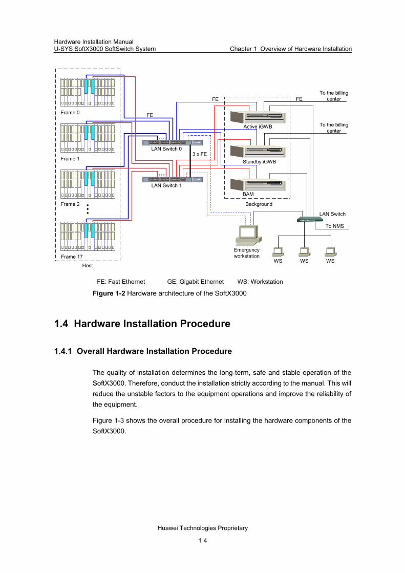
Figure 1-2 shows the hardware architecture of the SoftX3000.
Hardware Installation Manual U-SYS SoftX3000 SoftSwitch System Chapter 1 Overview of Hardware Installation
Huawei Technologies Proprietary
1-4
Frame 0
LAN Switch 0
LAN Switch 1BAM
Active iGWB
FE
3 x FE
FE
Host
Background
To the billingcenter
WS WS WS
LAN Switch
To NMS
FE
Emergencyworkstation
Frame 1
Frame 2
Frame 17
Standby iGWB
To the billingcenter
FE: Fast Ethernet GE: Gigabit Ethernet WS: Workstation
Figure 1-2 Hardware architecture of the SoftX3000
1.4 Hardware Installation Procedure
1.4.1 Overall Hardware Installation Procedure
The quality of installation determines the long-term, safe and stable operation of the SoftX3000. Therefore, conduct the installation strictly according to the manual. This will reduce the unstable factors to the equipment operations and improve the reliability of the equipment.
Figure 1-3 shows the overall procedure for installing the hardware components of the SoftX3000.

Hardware Installation Manual U-SYS SoftX3000 SoftSwitch System Chapter 1 Overview of Hardware Installation
Huawei Technologies Proprietary
1-5
Start
End
Preparations
Installing cabinets
Installing cabinet components
Installing power cables and protectiongrounding cables
Installing signal cables
Installing cabinet fittings
Installing peripherals
Hardware installation check
Figure 1-3 Procedure for installing hardware components of the SoftX3000
1.4.2 Introduction to Installation Preparations
In this step, you must read the related contents in this manual and the following two manuals:
U-SYS SoftX3000 SoftSwitch System Technical Manual U-SYS SoftX3000 SoftSwitch System Hardware Description Manual
Familiarize yourself with the overall hardware architecture and the technical specifications of the equipment, and the prerequisite for equipment installation:
Prepare installation tools.

Hardware Installation Manual U-SYS SoftX3000 SoftSwitch System Chapter 1 Overview of Hardware Installation
Huawei Technologies Proprietary
1-6
Install the auxiliary cabling rack or cabling trough according to the project design documents and the actual conditions of the equipment room.
1.4.3 Introduction to Installing Cabinets
In this step, you will do the following operations:
Install the cabinets Combine the adjacent cabinets according to the project design documents
1.4.4 Introduction to Installing Internal Components
In this step, according to the actual configuration, you will install some or all of the following components:
iGWB server BAM server Hard disk array LAN Switch Keyboard, video, mouse, and switcher (KVMS) Media resource server (MRS) Cabling trough Blank filler panel
Also insert the boards into the frames.
1.4.5 Introduction to Installing Power Cables and Protection Grounding Cables
After the cabinets are installed completely, you will install protection grounding cables.
This step has two purposes:
Ensure that the equipment is correctly grounded Prevent the equipment from electrostatic discharge (ESD) damage during the
subsequent installation
After installing the power cables, do not use them directly to power the system. Instead, Power on the system following the power-on steps after the quality checks and power-on test.
1.4.6 Introduction to Installing Signal Cables
The internal cables include:
Network cables Serial port cables

Hardware Installation Manual U-SYS SoftX3000 SoftSwitch System Chapter 1 Overview of Hardware Installation
Huawei Technologies Proprietary
1-7
Data cables Monitoring cables Internal clock cables
The external cables include:
External clock cables Trunk cables External network cables
1.4.7 Introduction to Installing Cabinet Fittings
This section introduces you to the installation of the cabinet fittings, including:
ESD-preventive floor holder Cabinet door lintel Front doors Back doors Side panels
1.4.8 Introduction to Installing Peripherals
This section introduces you to the installation of the peripherals, including:
Maintenance terminal system Alarm box Other network devices
1.4.9 Introduction to Hardware Installation Check
This step is a prerequisite of starting software installation.
Rectify the unqualified installation items according to the criteria.
For the checklist and criteria, refer to Chapter 9 "Hardware Installation Check" in this manual.
1.5 Installation Notices
This manual helps you install the hardware components and cables of the SoftX3000. However, the provided information might not cover all possible site conditions and optional devices in the actual installation procedure. Therefore, you need use specific methods based on the actual site conditions.
Before installation, carefully read the Site Survey Report to clarify the following contents:
The position and state of the equipment in the network

Hardware Installation Manual U-SYS SoftX3000 SoftSwitch System Chapter 1 Overview of Hardware Installation
Huawei Technologies Proprietary
1-8
Interface types of line transmission device Length of cables Accounting modes of access devices
To facilitate the installation, confirm whether or not the customer’s order for the equipment is changed greatly.

Hardware Installation Manual U-SYS SoftX3000 SoftSwitch System Chapter 2 Installation Preparations
Huawei Technologies Proprietary
2-1
Chapter 2 Installation Preparations
2.1 Introduction to the Chapter
This chapter contains the following sections:
Pre-Installation Tasks Checking Conditions of Equipment Room Unpacking and Accepting the Equipment
2.2 Pre-Installation Tasks
2.2.1 Preparing Technical Documents
You must carefully read the following technical documents before installation to get detailed information about the project.
Network Plan, Equipment Room Design, and Construction Diagram: Prepared by the design company consigned by you. The copies shall be provided to the equipment suppliers before delivery.
Site Survey Report: Filled out on site by the Huawei engineering personnel. Engineering Design Document: Delivered with the equipment. It is made by
Huawei based on the equipment configuration of each site. The documentation package: Delivered with the equipment. It is provided by
Huawei Technologies, Co., Ltd. The package includes Technical Manual, Hardware Description Manual, Installation Manual, Operation Manual and Maintenance Manual.
Other project related documents, including contracts and agreements, configuration table, and package list.
2.2.2 Organizing Installation Team
During the installation of the equipment, it is recommended to arrange your technical personnel to participate in installation training to get to know the system networking, equipment power supply, cable connection, and operation and maintenance, and to take over the equipment after installation.
The following two points must be noted when you are organizing the installation team:
With the project service mode, the installation procedure is conducted by technical personnel from the equipment supplier, and your technical personnel

Hardware Installation Manual U-SYS SoftX3000 SoftSwitch System Chapter 2 Installation Preparations
Huawei Technologies Proprietary
2-2
are for assistance. If the installation project is contracted out to the cooperation party entrusted by the supplier, the technical personnel from the contracted party must be strictly trained and examined by the supplier, to master the system installation and commissioning methods, and they cannot join in the system installation and debugging until obtaining the qualification admission;
With the supervision and debugging mode or supervision and service mode, the installation procedure is conducted by your technical personnel, and the technical personnel from the supplier are responsible for hardware installation check, supervision and technical support as the project supervisor.
2.2.3 Preparing Auxiliary Devices
I. Digital Distribution Frame
If E1 trunk cables are led out of the SoftX3000 cabinet in the networking scheme, the qualified digital distribution frame (DDF) must be configured according to the international requirements. Before the installation, you must complete the installation or expansion for the DDF. According to the capacity of the project and future expansion, the capacity of the DDF must be figured out. For the convenience of soldering the connectors of trunk cables at the DDF side, refer to the contract checklist for the model of the trunk cables used in the SoftX3000, or consult the engineering designer at local office.
II. Optical Transmission Equipment
If there is auxiliary optical transmission equipment, check the following items before the SoftX3000 hardware installation:
The optical transmission equipment has been installed. The optical transmitter and receiver have been installed and debugged. Optical fibers have been laid. The fiber tails from connection box are marked, The connectivity of the optical fibers has been checked. The cabling rack and distribution frame have been installed.
III. Interface to IP network
The SoftX3000 is connected to IP network through 100 Mbit/s standard Ethernet port, and then connected to the devices over the network. In this case, you must install routers and LAN Switches, and lay the network cables to prepare the interfaces to the IP network before installation, thus ensuring that the SoftX3000 can access the IP network normally.

Hardware Installation Manual U-SYS SoftX3000 SoftSwitch System Chapter 2 Installation Preparations
Huawei Technologies Proprietary
2-3
IV. Building Integrated Timing Supply System
The SoftX3000 provides embedded signaling gateway. When it also serves as signaling gateway to get interconnected with SS7 links, it must synchronize the clock of the links at the opposite end. If the building integrated timing supply system (BITS) is provided by you, you must complete installing the BITS and make access preparation before the SoftX3000 hardware installation.
2.2.4 Preparing Tools and Meters
The tools and meters as shown in Table 2-1 must be prepared before installation.
Table 2-1 List of tools and meters
Measuring and marking-off tools
Angle square, long tape, ruler(1 m), powder marker and pencil
Drilling tools
Percussion drill (one), drill bits (φ6, φ8, φ10, φ12, φ14, φ16), vacuum cleaner (one)
Firming tools
Straight screwdriver M3 – M6
Cross screwdriver M3 – M6
Monkey wrench, torque wrench
Socket wrench M10, M13, M16, M18
Double offset ring spanner M10, M13, M16, M18
Locksmith tools
Sharp-nose pliers, diagonal pliers, vice, hand-held electric drill, file, Handsaw, ripping bar, rubber hammer, nail hammer
General-purpose tools
Auxiliary tools
Brush, nippers, paper knife, bellows, electric iron, soldering tin wire, forklift, ladder
Special tools
Industrial horizontal ruler, ground resistance tester (optional), ESD-preventive wrist strap, cable winding gun, cable peeler (optional), pressing pincers (optional), pressing pincers with crystal head, wire punchdown tool (optional), SMB coaxial trunk self-ring cable
Meters Multimeter, 500 V megohm meter (used to measure the insulation impedance)

Hardware Installation Manual U-SYS SoftX3000 SoftSwitch System Chapter 2 Installation Preparations
Huawei Technologies Proprietary
2-4
Note:
The equipment supplier provides the list of tools and instruments, and you decide the suppliers of tools and meters.
All the meters must be qualified through the measurement calibration before use.
2.3 Checking Conditions of Equipment Room
2.3.1 Introduction to Checking Procedure
Upon arrival on site, the project supervisor must check the construction conditions according to Project Technical Specifications and Inspection Specifications for the Lightning Protection and Grounding of Communications Equipment, and fill out the Installation Environment Checklist based on the check results. After confirming that all conditions are ready, sign Kickoff Agreement with the customer and formulate the Project Installation Plan. In case the project preparation made by the customer is not sufficient to meet the kickoff requirement, fill up the “Onsite Work Liaison Form” to state the reasons to the customer. If the customer insists on kicking off the installation, the customer should commit the completion time for project preparation and sign it. For a project in which the rework is impossible or the rework still fails to meet the project requirement, a memo is required to be signed between the parties.
2.3.2 Checking Building Conditions of Equipment Room
Check the area, height, load bearing capacity, and groove distribution of the equipment room. If any item does not meet the requirements, suggest the customer to reconstruct.
2.3.3 Checking Environment Conditions
The check items include:
The illumination conditions must satisfy the requirements for equipment maintenance. There must be normal illumination, standby illumination, and emergency illumination systems.
The air-conditioning and ventilation systems can ensure the temperature and humidity requirements.
Effective ESD-preventive measures are taken. The equipment room has sufficient fire-fighting facilities. The equipment room meets the quake-proof requirements. The floor in the
equipment room is solid enough to install and fasten the equipment.

Hardware Installation Manual U-SYS SoftX3000 SoftSwitch System Chapter 2 Installation Preparations
Huawei Technologies Proprietary
2-5
Safe lightning-proof measures are taken for the equipment room.
2.3.4 Checking Power Supply Conditions
The check items include:
The AC power supply facilities are complete, and the power meets the requirement. Besides the mains power supply, there must be standby power supply by diesel generator.
The DC power distribution devices can provide stable power supply, and the output voltage is within the specified range.
There are enough available storage batteries to ensure the equipment able to run in case of power supply accident.
The AC power distribution system has independent AC protection ground.
2.3.5 Checking Grounding Conditions
Good grounding is the basis ensuring the stable running of the equipment, and preventing the equipment from lightning and interference. In this case, it is required to carefully check the grounding conditions of the site, and take correct grounding measures.
The grounding impedance for the equipment building must be not more than 1Ω.
The grounding impedance of the equipment must meet the relative stipulation of the country if it is stricter than the specifications shown in Table 2-2.
Table 2-2 Grounding impedance requirements for switching equipment
Capacity of equipment Grounding impedance
Less than 2000 local subscribers ≤5Ω
Not more than 10000 local subscribers
Not more than 2000 toll calls ≤3Ω
More than 10000 local subscribers
More than 2000 toll calls ≤ 1Ω
2.3.6 Checking Auxiliary Devices
The SoftX3000 is running over the network. Before installing the SoftX3000, it is required to check whether the auxiliary transmission devices are installed, for example, whether the optical terminator is installed and commissioned, whether optical fibers are laid, and whether cabling rack and cable distribution rack are installed.

Hardware Installation Manual U-SYS SoftX3000 SoftSwitch System Chapter 2 Installation Preparations
Huawei Technologies Proprietary
2-6
2.3.7 Checking Other Facilities
There must be a workbench in compliance with ESD-preventive requirements in the control room, used to install maintenance terminal, network management workstation and printer.
Desk, chair, power socket for computer, and phone set are necessary during installation. It is required to prepare for any possibilities according to the site conditions.
2.4 Unpacking and Accepting the Equipment
2.4.1 Unpacking Requirements
After the project begins, the project supervisor should check the goods together with the customer.
First check whether the total number of goods against the packing list attached to the packing box, whether the destination address of goods is consistent with the actual installation site, whether the physical appearance of the packing case is good and whether the chassis is placed correctly.
If such things as serious damage to the outer package, water on the outside packaging box, or rust/water on the equipment is identified, stop unpacking immediately and find the cause. Then, feed back the situation to the local representative office.
Caution:
To protect the equipment and find out the cause, place the unpacked equipment indoor for proper storage and shot the site storage environment, the rusted or corroded equipment/packing boxes/packaging materials. Then, properly keep these photos and store the unpacked packing boxes as well as packaging materials.
Now, open the case marked with the label indicating “Packing list inside”, take out the packing list, and check the goods against the list. In case any good is wrong or missing, please fill out Goods Error Feedback Form. In case any good is damaged, please fill out Goods Replacement Application Form, and finally fill out the Packing List together with the customer.

Hardware Installation Manual U-SYS SoftX3000 SoftSwitch System Chapter 2 Installation Preparations
Huawei Technologies Proprietary
2-7
Caution:
During the transportation and handling of products, spare parts or components, make sure to avoid the collision of such things against doors, walls or shelves.
When transporting, handling and installing the equipment, it is forbidden to reach the uncoated metal surface of equipment parts or components with sweaty or dirty gloves.
2.4.2 Unpacking Wooden Crate
I. Overview of Unpacking Wooden Crate
Caution:
The wooden case is direction-oriented and should not be placed upside down. Otherwise, fatal damages would be caused to the product.
Wooden crate is used to package cabinets and batteries. A packaged cabinet is composed of wooden board, angle steel, tongue, and foam corner protector. Before unpacking the wooden crate, move the packing crate to the equipment room or nearby (if there is sufficient space), to avoid damage to the cabinet when moving the cabinet.
II. Operation Procedures of Unpacking Wooden Crate
The unpacking steps are as follows.
1) Insert the spanner into the tongue holes in the cover, and turn the spanner to straighten the tongues, as shown in Figure 2-1. You can also use screwdriver or hammer to straighten the tongues.

Hardware Installation Manual U-SYS SoftX3000 SoftSwitch System Chapter 2 Installation Preparations
Huawei Technologies Proprietary
2-8
(1)(2)
(3)
(4)
(1) Angle steel (2) Wooden board (3) Tongue (4) Spanner
Figure 2-1 Straightening the tongue
2) Lift and remove the covers, as shown in Figure 2-2.
Figure 2-2 Removing the cover
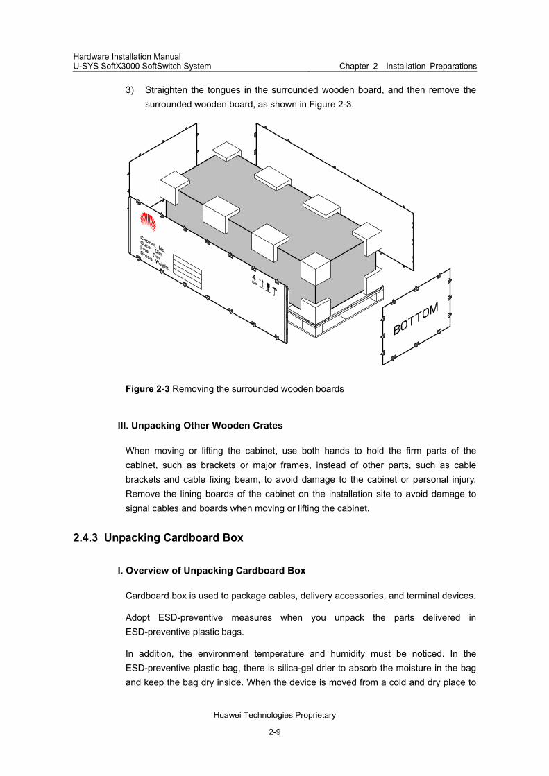
Hardware Installation Manual U-SYS SoftX3000 SoftSwitch System Chapter 2 Installation Preparations
Huawei Technologies Proprietary
2-9
3) Straighten the tongues in the surrounded wooden board, and then remove the surrounded wooden board, as shown in Figure 2-3.
Figure 2-3 Removing the surrounded wooden boards
III. Unpacking Other Wooden Crates
When moving or lifting the cabinet, use both hands to hold the firm parts of the cabinet, such as brackets or major frames, instead of other parts, such as cable brackets and cable fixing beam, to avoid damage to the cabinet or personal injury. Remove the lining boards of the cabinet on the installation site to avoid damage to signal cables and boards when moving or lifting the cabinet.
2.4.3 Unpacking Cardboard Box
I. Overview of Unpacking Cardboard Box
Cardboard box is used to package cables, delivery accessories, and terminal devices.
Adopt ESD-preventive measures when you unpack the parts delivered in ESD-preventive plastic bags.
In addition, the environment temperature and humidity must be noticed. In the ESD-preventive plastic bag, there is silica-gel drier to absorb the moisture in the bag and keep the bag dry inside. When the device is moved from a cold and dry place to

Hardware Installation Manual U-SYS SoftX3000 SoftSwitch System Chapter 2 Installation Preparations
Huawei Technologies Proprietary
2-10
a warmer and wetter place, do no unpack until 30 minutes later. Otherwise, the moisture will condense on the surface of the device, and damage it.
II. Operation Procedures of Unpacking Cardboard Box
The unpacking steps are as follows:
1) Check the label on the cardboard box to get information about the type and quantity of the components in the box.
2) Use tilted-nose pliers to cut the packaging straps. 3) Use paper knife to cut the tapes along the seam of box cover.
Do not insert the knife too deep, or you will scratch the internal device.
4) Open the cardboard box. 5) Check the components in the boxes based on the packing checklist. 6) Sign the acceptance document.
Do NOT discard cardboard box with components left inside to avoid troubles to the installation. It is recommended that one person is responsible for one cardboard box. Before unpacking next cardboard box, be sure to check the current cardboard box to see if it is empty.

Hardware Installation Manual U-SYS SoftX3000 SoftSwitch System Chapter 3 Installing Cabinets
Huawei Technologies Proprietary
3-1
Chapter 3 Installing Cabinets
3.1 Introduction to the Chapter
This chapter contains the following sections:
Introduction to Cabinet Installing Cabinets on ESD-Preventive Floor Installing Cabinets on Cement Floor
3.2 Introduction to Cabinet
The SoftX3000 adopts standard 19-inch N68-22 cabinet, made of sheet metal and featuring simple structure and universal usability. Three cabinets can satisfy the requirement for full configuration of the SoftX3000.
According to different equipment rooms, a cabinet can be installed on cement floor or ESD-preventive floor. If two or more cabinets are placed in the same row, they must be connected and fixed.
Note:
Wear clean gloves when touching the surfaces of cabinets or frames.
3.3 Installing Cabinets on ESD-Preventive Floor
3.3.1 Reference of N800 Support
If N68-22 cabinets are installed in the equipment room with ESD-preventive floor, N800 series supports are used. Refer to chapter 1 “Cabinet and Internal Components” of U-SYS SoftX3000 SoftSwitch System Hardware Description Manual for the introduction of N800 support.
3.3.2 Introduction to Installation Procedure on ESD-Preventive Floor
Figure 3-1 shows the procedure for installing cabinets on ESD-preventive floor.

Hardware Installation Manual U-SYS SoftX3000 SoftSwitch System Chapter 3 Installing Cabinets
Huawei Technologies Proprietary
3-2
Plan support positions
Install supports and slide rails
Install ESD-preventive floorholder fixing components
Position cabinets
Level cabinets
Combine cabinets
Fix cabinets
Pass theinsulation test?
Y
N
Start
End
Figure 3-1 Procedure for installing cabinets on ESD-preventive floor
When two or more cabinets are placed in the same row, they must be connected and fixed. Generally, internal components and cables are installed before the floor holder installation, floor recovering, door lintel installation and door installation are implemented. For detailed information, see Chapter 7 "Installing Cabinet Fittings" in this manual.
3.3.3 Planning Support Positions
I. Determining cabinet positions
Before installing cabinets, plan available space of the equipment room. Keep sufficient space around cabinets for maintenance and operation purposes, as shown in Figure 3-2 and Figure 3-3.

Hardware Installation Manual U-SYS SoftX3000 SoftSwitch System Chapter 3 Installing Cabinets
Huawei Technologies Proprietary
3-3
II. Marking installation hole positions
To mark installation hole positions, do as follows:
1) Specify installation positions for the supports with reference to the benchmark dimensions and the support dimensions specified in the construction plan.
2) Mark a few points for line drawing with a long tape, and draw two straight lines parallel to the benchmark with a distance of 690 mm between them.
3) According to the design requirements, specify the installation holes for the first support on the two lines.
4) With these holes as reference, mark the installation holes for other supports one by one.
5) To avoid faults, measure all location lines again after marking the holes to ensure correct dimensions.
Figure 3-2 shows the holes for installing supports for a single cabinet. Figure 3-3 shows the holes for installing supports for multiple cabinets in a row.
800
690 800
800
800
800
354
600
4- 16∅
Figure 3-2 Hole positions for installing support for a single cabinet

Hardware Installation Manual U-SYS SoftX3000 SoftSwitch System Chapter 3 Installing Cabinets
Huawei Technologies Proprietary
3-4
800
800
800
600
800
800
4- 16
600 600
354
690
354 354
∅
Figure 3-3 Hole positions for installing supports for multiple cabinets in a row
It is also available to use line drawing template to mark the positions of the expansion bolt holes. Based on the cabinet layout, place the line drawing template on the floor, as shown in Figure 3-4. To mark the hole positions for all expansion bolts on the floor, use the template (each cabinet has four expansion bolts). The half-circle gap on the template indicates the front direction of the cabinet.

Hardware Installation Manual U-SYS SoftX3000 SoftSwitch System Chapter 3 Installing Cabinets
Huawei Technologies Proprietary
3-5
Front
Back
RightLeft
800
354
600
690
Figure 3-4 Line drawing template (used for installation on ESD-preventive floor)
Note:
Be sure to use the template in correct direction.
III. Drilling holes
To fix supports onto ground with M12 expansion bolts, it is required to drill holes for the expansion bolts using a percussion drill with bit φ16.
To drill a hole, do as follows:
1) Keep the drilling bit vertical to the ground and hold tight the drillstock to make holes 52 mm to 60 mm deep. The depth of the holes must be within 52 mm to 60 mm. Otherwise the expansion bolts cannot be fastened. Make sure that the depths of all holes are the same.
2) Clean the dust inside the holes with a vacuum cleaner. 3) Measure the depth to make sure that the depths of all holes are the same.
If the ground is too hard or smooth to settle the drill bit, punch a sample pit first for easy drilling.

Hardware Installation Manual U-SYS SoftX3000 SoftSwitch System Chapter 3 Installing Cabinets
Huawei Technologies Proprietary
3-6
Drawing lines and drilling holes are the fundamental work for hardware installation. Good quality is the prerequisite to guarantee the quality of the overall installation. If the accuracy is not high enough, the future work will be greatly affected.
Note:
The depth of drilled hole must be 52 mm to 60 mm. A depth less than 52 mm or more than 60 mm will cause the expansion bolt unable to be installed or fastened.
3.3.4 Installing Supports and Slide Rails
I. Installing expansion bolts
Before fixing expansion bolts, clean up the dust inside and around the holes with a vacuum cleaner. Measure the distance between the holes, and place the supports to check whether the supports and holes match exactly. For the holes with big deviation, plan and drill new holes before installing expansion bolts in them.
To install an expansion bolt, do as follows:
1) Take expansion tube and nut off the expansion bolt, and put them vertically into a hole after guiding rib on expansion nut has been inserted in to guiding slot of the expansion tube.
2) Strike directly on expansion tube with a rubber hammer until it is completely driven into the ground.
Figure 3-5 shows the installation of expansion tube and expansion nut.
(1)
(2)
(3)
(4)
(1) Expansion tube (2) Guiding slot of expansion tube (3) Expansion nut (4) Guiding rib of expansion nut
Figure 3-5 Installation of expansion tube and expansion nut

Hardware Installation Manual U-SYS SoftX3000 SoftSwitch System Chapter 3 Installing Cabinets
Huawei Technologies Proprietary
3-7
Note:
The guiding rib on expansion nut must be inserted into the guiding slot on expansion tube before the tube is driven into the ground. Otherwise, the expansion bolt could not be installed and fastened normally.
II. Adjusting support height
To ensure that the upper surface of slide rails and the upper surface of ESD-preventive floor are on the same level after the supports and sidle rails are assembled, it is required to adjust all the supports to the preset height before installation.
To adjust the support height, do as follows:
1) Measure the height of the upper surface of the ESD-preventive floor. 2) Make the value minus the height of the slide rail (50 mm) to get the preset height of
the supports. 3) According to the ESD-preventive floor height mark on the supports, adjust all the
supports to the preset height and tighten the height-locking bolts to 45 Nm with a torque spanner.
4) Tighten the bolts in the middle and then those at both sides, as shown in Figure 3-6.
(1)
(2) (1) Height-locking bolt (middle) (2) Height-locking bolt (side)
Figure 3-6 Connection of support and floor
III. Assembling supports and slide rails
To assemble the supports and slide rails, do as follows:

Hardware Installation Manual U-SYS SoftX3000 SoftSwitch System Chapter 3 Installing Cabinets
Huawei Technologies Proprietary
3-8
1) Assemble the supports and slide rails together with M12x30 bolts, spring washers and flat washers, as shown in Figure 3-7.
2) Correct the support positions before fastening all bolts to make the diagonal lines (A and B shown in Figure 3-7) of the two slide rails are equal in length.
B
A
Figure 3-7 Assembly of support and slide rails
IV. Fixing supports
To fix the supports, do as follows:
1) Align the support installation holes with the corresponding expansion bolt holes. 2) Fit the spring and flat washers on M12x60 bolts, and insert the bolts vertically into
the expansion bolt holes through the support installation holes. 3) Correct the support positions and screw M12x60 bolts to 45 Nm, as shown in
Figure 3-8.

Hardware Installation Manual U-SYS SoftX3000 SoftSwitch System Chapter 3 Installing Cabinets
Huawei Technologies Proprietary
3-9
(1)(2)(3)
(1) Bolt M12x60 (2) Spring washer 12 (3) Flat washer 12
Figure 3-8 Assembly of supports and slide rails
When installing supports for a row of cabinets, align all supports by front side and keep the spacing between adjacent supports as 128 mm for convenience of connecting cabinets, as shown in Figure 3-9.
128
Figure 3-9 Relative positions of supports

Hardware Installation Manual U-SYS SoftX3000 SoftSwitch System Chapter 3 Installing Cabinets
Huawei Technologies Proprietary
3-10
3.3.5 Installing Holder Fixing Components
Floor holder fixing components are used to fix front floor holder and back floor holder. Before the cabinets are positioned, the floor holder fixing components must be fixed under the slide rails, as shown in Figure 3-10.
(1)
(1) Holder fixing
Figure 3-10 Installation of floor holder fixing components
3.3.6 Leveling Cabinets
I. Positioning cabinets
To position a cabinet, do as follows:
1) Determine the front view of a cabinet. 2) Lift it onto slide rails. 3) Align the four fixing holes in the cabinet with the four holes in the slide rails.
II. Installing insulation plates
Put the installation plates on the slide rails under the cabinet, as shown in Figure 3-11. Each cabinet requires two insulation plates.

Hardware Installation Manual U-SYS SoftX3000 SoftSwitch System Chapter 3 Installing Cabinets
Huawei Technologies Proprietary
3-11
(3)
(1)(2)
(4)(5)
(6)
(1) Bolt M12x45 (2) Spring washer 12 (3) Insulating plate (4) Washer (5) Flat washer 12, nut 12 (6) Slide rail
Figure 3-11 Leveling and fixing a cabinet
III. Leveling cabinets
To level the cabinets, do as follows:
1) Place horizontal rulers in both longitudinal and latitudinal directions on the top surface of the cabinet to check the levelness.
2) Use washers to adjust the cabinet height to keep the cabinet horizontal, as shown in Figure 3-11.
Note:
The washers for leveling must be installed between the insulation plates and slide rails. Otherwise, insulation will not work.

Hardware Installation Manual U-SYS SoftX3000 SoftSwitch System Chapter 3 Installing Cabinets
Huawei Technologies Proprietary
3-12
3.3.7 Fixing Cabinets
I. Fixing bottom of cabinet
To fix the cabinet bottom, do as follows:
1) Fit the spring washers on M12x45 bolts (the big flat washers and insulation coverings have been installed in the cabinet).
2) Insert the bolts vertically into the connection holes in the slide rails through the lower enclosure frame of the cabinet.
3) Fit the flat washers and nuts and screw M12x45 bolts to 45 Nm, as shown in Figure 3-11. Be sure to fasten the bolts in cross way to reduce the stress between bolts and cabinet.
II. Fixing top of combined cabinets
When two or more cabinets are installed, they must be combined. The cabinets are combined and fixed by connecting plates.
The connecting plates for combining cabinets are installed on the top of cabinets and they are delivered with cabinets, as shown in Figure 3-12.
To connect two adjacent cabinets, do as follows:
1) Disassemble the connecting plates of the two adjacent cabinets. 2) Reassemble them according to Figure 3-12

Hardware Installation Manual U-SYS SoftX3000 SoftSwitch System Chapter 3 Installing Cabinets
Huawei Technologies Proprietary
3-13
1 2 3
4 5 6 7
Figure 3-12 Installation of connecting plate for combining cabinets
3.3.8 Performing Insulation Test
To test the insulation effect of the cabinets, do as follows:
1) Set the multimeter to megohm range. 2) Measure the impedance between the supports and cabinets.
If the impedance measured is more than 5 megohm, it indicates that the cabinets are insulated from the supports. In this case, you can end the installation.
Otherwise, do as follows:
1) Disassemble all installed components. 2) Check whether the insulation parts have been installed or whether the insulation
parts have been damaged.

Hardware Installation Manual U-SYS SoftX3000 SoftSwitch System Chapter 3 Installing Cabinets
Huawei Technologies Proprietary
3-14
3.4 Installing Cabinets on Cement Floor
3.4.1 Introduction to Installation Procedure on Cement Floor
If N68-22 cabinet is installed on cement floor, it can be fixed by expansion bolts directly.
Caution:
During installation, the insulation plates between each cabinet and floor, as well as the insulation coverings for expansion bolts must be correctly installed, to make the whole set of equipment insulated from the ground before protection grounding cables are connected, and to meet the insulation requirements.
Figure 3-13 shows the procedure of installing cabinet on cement floor.
Start
Plan cabinet positions
Install expansion bolts
Position cabinets
Level cabinets
Combine cabinets
Fix cabinets
Pass theinsulation test?
End
Y
N
Figure 3-13 Procedure for installing cabinets on cement floor

Hardware Installation Manual U-SYS SoftX3000 SoftSwitch System Chapter 3 Installing Cabinets
Huawei Technologies Proprietary
3-15
When two or more cabinets are placed in the same row, they must be combined and fixed.
3.4.2 Planning Cabinet Positions
I. Determining cabinet positions
Before installing cabinets, plan the available space of the equipment room. Keep sufficient space around the cabinets for maintenance and operation purposes, as shown in Figure 3-14 and Figure 3-15.
II. Marking installation hole positions
To mark installation hole positions, do as follows:
1) Specify the positions for the expansion bolts with reference to the dimensions of planned positions and the dimensions of the holes for installing cabinet specified in the construction plan.
2) Mark a few points for line drawing with a long tape and draw two straight lines parallel to the benchmark with a distance of 687 mm between them.
3) According to the design requirements, specify the expansion bolt holes for the first cabinet.
4) With these holes as reference, mark the expansion bolt holes for other cabinets one by one.
5) To avoid faults, measure all location lines again after marking the holes, to ensure correct dimensions.
Figure 3-14 shows the layout of expansion bolt holes for a single cabinet. Figure 3-15 shows the layout of expansion bolt holes for multiple cabinets in a row.

Hardware Installation Manual U-SYS SoftX3000 SoftSwitch System Chapter 3 Installing Cabinets
Huawei Technologies Proprietary
3-16
800
687 800
800
800
800
413
600
4- 16∅
Figure 3-14 Hole positions for expansion bolts used for a single cabinet

Hardware Installation Manual U-SYS SoftX3000 SoftSwitch System Chapter 3 Installing Cabinets
Huawei Technologies Proprietary
3-17
800
800
800
600
800
800
4- 16
600 600
413
687
413 413
∅
Figure 3-15 Hole positions for expansion bolts used for multiple cabinets in a row
It is also available to use line drawing template to mark the positions of the expansion bolt holes. Based on the cabinet layout, place the line drawing template on the floor, as shown in Figure 3-16. To mark the hole positions for all expansion bolts on the floor, use the template (each cabinet has four expansion bolts). The half-circle gap on the template indicates the front direction of the cabinet.

Hardware Installation Manual U-SYS SoftX3000 SoftSwitch System Chapter 3 Installing Cabinets
Huawei Technologies Proprietary
3-18
Front
Back
RightLeft
800
600
687
413
Figure 3-16 Line drawing template (used for installation on cement floor)
Note:
Be sure to use the template in correct direction.
III. Drilling holes
To fix cabinets onto ground with M12 expansion bolts, it is required to drill holes for expansion bolts using a percussion drill with bit φ16.
To drill a hole, do as follows:
1) Keep the drilling bit vertical to the ground and hold tight the drillstock to make holes 52 mm to 60 mm deep. The depth of the holes must be within 52 mm to 60 mm. Otherwise the expansion bolts cannot be fastened. Make sure that the depths of all holes are the same.
2) Clean the dust inside the holes with a vacuum cleaner. 3) Measure the depth to make sure that the depths of all holes are the same.
If the ground is too hard or smooth to settle the drill bit, punch a sample pit first for easy drilling.

Hardware Installation Manual U-SYS SoftX3000 SoftSwitch System Chapter 3 Installing Cabinets
Huawei Technologies Proprietary
3-19
Drawing lines and drilling holes are the fundamental work for hardware installation. Good quality is the prerequisite to guarantee the quality of the overall installation. If the accuracy is not high enough, the future work will be greatly affected.
Note:
The depth of the drilled hole must be 52 mm to 60 mm. A depth less than 52 mm or more than 60 mm will cause the expansion bolt unable to be installed or fastened.
IV. Installing expansion bolts
Before fixing expansion bolts, clean up the dust inside and around the holes using a vacuum cleaner. Measure the distance between the holes. For the holes with big deviation, plan and drill new holes before installing expansion bolts in them.
To install an expansion bolt into a hole, do as follows:
1) Take the expansion tube and nut off the expansion bolt. 2) Put them vertically into the hole after guiding rib on expansion nut has been
inserted into the guiding slot of the expansion tube. 3) Strike directly on expansion tube with a rubber hammer until it is completely driven
into the ground.
Figure 3-5 shows the installation of expansion tube and expansion nut.
3.4.3 Leveling Cabinets
I. Positioning cabinets
To position a cabinet as shown in Figure 3-17, do as follows:
1) Lay insulation plates on the floor (two plates for each cabinet). 2) Place a cabinet at the planned position. 3) Align the installation holes in the cabinet with the corresponding expansion bolt
holes.
II. Leveling cabinet
To level the cabinets, do as follows:
1) Place horizontal rulers in both longitudinal and latitudinal directions on the top surface of cabinets to check the levelness of the cabinets.
2) Use washers under the insulation plates to adjust the cabinet height to keep the cabinets horizontal, as shown in Figure 3-17.

Hardware Installation Manual U-SYS SoftX3000 SoftSwitch System Chapter 3 Installing Cabinets
Huawei Technologies Proprietary
3-20
3) Align all cabinets.
(1)
(2)
(3)
(4)
(1) Bolt M12x70 (2)Spring washer 12 (3) Insulating plate (4) Washer
Figure 3-17 Placing and securing the cabinet
Note:
The washers for leveling must be installed between insulation plates and floor. Otherwise, insulation will not work.
3.4.4 Fixing Cabinets
I. Fixing bottom of cabinet
To fix the cabinet bottom, do as follows:
1) Fit the spring washers on M12x70 bolts (the big flat washers and insulation coverings have been installed in the cabinet).
2) Insert the bolts vertically into the expansion bolt holes in the slide rails through the lower enclosure frame of the cabinet.
3) Screw M12x70 bolts to 45 Nm, as shown in Figure 3-17.

Hardware Installation Manual U-SYS SoftX3000 SoftSwitch System Chapter 3 Installing Cabinets
Huawei Technologies Proprietary
3-21
II. Fixing top of combined cabinets
When two or more cabinets are installed, they must be combined and fixed by connecting plates.
The connecting plates for combining two cabinets are installed on the top of cabinets and they are delivered with cabinets, as shown in Figure 3-18.
To combine two adjacent cabinets, do as follows:
1) Disassemble the connecting plates of the two adjacent cabinets.
Reassemble them according to Figure 3-18.
1 2 3
4 5 6 7
Figure 3-18 Installation of connecting plate for combining cabinets
3.4.5 Performing Insulation Test
To test the insulation effect of the cabinets, do as follows:

Hardware Installation Manual U-SYS SoftX3000 SoftSwitch System Chapter 3 Installing Cabinets
Huawei Technologies Proprietary
3-22
1) Set the multimeter to megohm range. 2) Measure the impedance between expansion bolts M12x70 and cabinets.
If the impedance measured is more than 5 megohm, it indicates that the cabinets are insulated from the expansion bolts. In this case, you can end the installation.
Otherwise, do as follows:
1) Disassemble all installed components. 2) Check whether the insulation parts have been installed or whether the insulation
parts have been damaged.
Hardware Installation Manual U-SYS SoftX3000 SoftSwitch System Chapter 4 Installing Internal Components
Huawei Technologies Proprietary
4-1
Chapter 4 Installing Internal Components
4.1 Introduction to the Chapter
This chapter contains the following sections:
Introduction to Internal Components and Installation Installing Internal Components
4.2 Introduction to Internal Components and Installation
4.2.1 Introduction to Internal Components
Based on different internal components configured, the N68-22 cabinets can be divided into integrated configuration cabinet, service processing cabinet, media resource service (MRS) cabinet.
The internal components in the integrated configuration cabinet include iGWB server, BAM server, hard disk array, LAN Switch, KVMS, and basic and expansion frames. Figure 4-1 shows the full configuration of an integrated configuration cabinet.

Hardware Installation Manual U-SYS SoftX3000 SoftSwitch System Chapter 4 Installing Internal Components
Huawei Technologies Proprietary
4-2
Power distribution frame(2U)
Expansion frame/Mediaresource frame/MRS6100
(9U)
Air deflector (2U)
Basic frame (9U)
Air deflector (2U)
Blank filler panel (1U)KVMS(1U)
LAN Switch 3 (1U)Cabling trough (1U)LAN Switch 2 (1U)Cabling trough (1U)
Blank filler panel (3U)
BAM(2U)
Standby iGWB (2U)
Active iGWB (2U)
LAN Switch 1 (1U)Cabling trough (1U)LAN Switch 0 (1U)
Blank filler panel (2U)
Blank filler panel (2U)
Figure 4-1 Full configuration of integrated configuration cabinet

Hardware Installation Manual U-SYS SoftX3000 SoftSwitch System Chapter 4 Installing Internal Components
Huawei Technologies Proprietary
4-3
Note:
The active iGWB server is labeled as iGWB (M), and the standby iGWB server as iGWB (S).
The number of service processing cabinets configured is determined based on the system capacity. Figure 4-2 shows the full configuration of four service processing cabinets. The frames are installed from bottom to top according to the specific system capacity.
Basic frame (9U)
Media resource frame/expansion frame (9U)
Power distribution frame (2U)
Air deflector (2U)
Expansion frame (9U)
Blank filler panel (2U)
Service processing cabinet 1 Service processing cabinet 2 Service processing cabinet 3 Service processing cabinet 4
Power distribution frame (2U) Power distribution frame (2U) Power distribution frame (2U)
Media resource frame/expansion frame (9U)
Media resource frame/expansion frame (9U)
Media resource frame(9U)
Air deflector (2U) Air deflector (2U) Air deflector (2U)
Expansion frame (9U) Expansion frame (9U) Expansion frame (9U)
Expansion frame (9U)Expansion frame (9U)Expansion frame (9U)Expansion frame (9U)
Expansion frame (9U) Expansion frame (9U) Expansion frame (9U)
Air deflector (2U) Air deflector (2U) Air deflector (2U) Air deflector (2U)
Air deflector (2U)Air deflector (2U) Air deflector (2U) Air deflector (2U)
Blank filler panel (2U) Blank filler panel (2U) Blank filler panel (2U)
Figure 4-2 Full configuration of service processing cabinets
Three service processing cabinets can meet the requirements for the full configuration of the system. When there are more than one service processing cabinets, the second service processing cabinet must be configured with a basic frame in the first frame position.
If the SoftX3000 system has no independent MRS, media resource frames must be configured in the service processing cabinet, and media resource boards are installed

Hardware Installation Manual U-SYS SoftX3000 SoftSwitch System Chapter 4 Installing Internal Components
Huawei Technologies Proprietary
4-4
in the frames. If the SoftX3000 system has independent MRS, it is not required to configure media resource frames in the service processing cabinet. In the MRS cabinet, only MRS is configured, as shown in Figure 4-3.
MRS (13U)
Power distribution frame (2U)
Blank filler panel (3U)
Blank filler panel (3U)
Blank filler panel (3U)
Blank filler panel (2U)
Blank filler panel (2U)
Blank filler panel (2U)
Blank filler panel (2U)
Blank filler panel (2U)
Blank filler panel (3U)
Blank filler panel (3U)
Blank filler panel (3U)
Blank filler panel (3U)
Figure 4-3 Configuration of MRS cabinet

Hardware Installation Manual U-SYS SoftX3000 SoftSwitch System Chapter 4 Installing Internal Components
Huawei Technologies Proprietary
4-5
4.2.2 Installation Procedure
Figure 4-4 shows the procedure for installing internal components.
Cabinet installation completed
Component installation completed
Installing iGWB server
Installing MRS
Installing BAM
Installing KVMS
Installing LAN Switch
Installing hard disk array
Figure 4-4 Installation process of intra-cabinet components
4.2.3 Installation Notices
When installing internal components, it is required to place each component with care into corresponding guide rails in the cabinet, and then insert it slightly into the cabinet. The component installation sequence inside the cabinet is from bottom upward for the sake of cabinet stability and convenience in operation.
When fixing internal components and blank filler panels, it is required to put the bolts into the installation holes on the mount angles of each component, and then fix the component on the mount angles at both sides of the cabinet. If there are more than two bolts for a component, it is required to first fix the four bolts at the four corners in diagonal direction, and then fasten other bolts in sequence.
Blank filler panel is fixed on the mount angles at both sides of the cabinet by lockers. To pull out blank filler panel, you must first press down the lockers and then loose them.

Hardware Installation Manual U-SYS SoftX3000 SoftSwitch System Chapter 4 Installing Internal Components
Huawei Technologies Proprietary
4-6
During installation, you must ensure the mount angles in correct order, to keep even space between components, between blank filler panels, and between component and blank filler panel.
4.3 Installing Internal Components
4.3.1 Installation Requirements
The iGWB server, BAM server, hard disk array, LAN Switch and KVMS must be installed in corresponding frames in the integrated configuration cabinet and service processing cabinet in the sequence from bottom to top. The MRS is configured in a separate cabinet.After the above components have been installed, refer to the methods introduced in Chapter 5 "Installing Power Cables and Protection Grounding Cables" in this manual to connect protection grounding cables of the cabinets, and of basic and expansion frames, and then insert the boards into basic and expansion frames.
4.3.2 Installing iGWB and BAM Servers
Note:
The guide rails delivered with the servers cannot be used in the SoftX3000 cabinet. The guide rails for the internal components of the cabinet have been assembled before delivery.
The installation steps are as follows:
1) Put the iGWB server and BAM server on the corresponding positions. 2) Fix the mount angles of the servers to the mount angles on the lateral columns in
front of the cabinet with the captive screws delivered with the servers.
4.3.3 Installing Hard Disk Array
This step is available only when iGWB uses IBM server.
The installation steps are as follows:
1) Place the hard disk array into the corresponding position in the integrated configuration cabinet.
2) Fix the mount angles on both sides of the hard disk array onto the mount angles on the lateral columns in front of the cabinet with panel fasteners.

Hardware Installation Manual U-SYS SoftX3000 SoftSwitch System Chapter 4 Installing Internal Components
Huawei Technologies Proprietary
4-7
4.3.4 Installing LAN Switch
Caution:
Do not use the mount angle delivered with the LAN Switch. Use the one delivered with the SoftX3000 cabinet.
The mount angle is Huawei purple-gray, which is consistent with the color of the cabinet.
The installation steps are as follows:
1) Install the mount angles of LAN Switch. 2) Place the LAN Switch onto corresponding guide rails and insert it. 3) Fix the LAN Switch with captive fasteners.
4.3.5 Installing KVMS
The installation steps are as follows:
1) Place the KVMS into corresponding position in the integrated configuration cabinet.
2) Fix the mount angles on both sides of the KVMS onto the mount angles on the lateral columns in front of the cabinet with captive fasteners delivered with the iGWB server and BAM server.
3) Install anti-tilt angles on the two rear sides of the KVMS to avoid tilt of the rear part when the LCD/keyboard is pulled out of the cabinet.
4) Fix the anti-tilt angles to the mount angles on the lateral columns at the back of the cabinet with screws.
4.3.6 Installing MRS
The installation steps are as follows:
1) Place the MRS onto the guide rails in corresponding frame.Insert it into the cabinet on an even level.Fix the mount angles on both sides of the MRS onto the mount angles on the lateral columns in front of the cabinet with panel fasteners.

Hardware Installation Manual U-SYS SoftX3000 SoftSwitch System Chapter 4 Installing Internal Components
Huawei Technologies Proprietary
4-8
Note:
The MRS is an optional device of the system. If the system adopts the media resource frame (configured with MRCA/MRIA boards) as the embedded MRS, this step can be omitted.

Hardware Installation Manual U-SYS SoftX3000 SoftSwitch System
Chapter 5 Installing Power Cables and Protection Grounding Cables
Huawei Technologies Proprietary
5-1
Chapter 5 Installing Power Cables and Protection Grounding Cables
5.1 Introduction to the Chapter
This chapter contains the following sections:
Introduction to Power Supply System and Protection Grounding System Installing Power Cables and Protection Grounding Cables Installing Power Bus Cables from DC Power Distribution Cabinet to DC
Switchboard
5.2 Introduction to Power Supply System and Protection Grounding System
5.2.1 Introduction to Power Supply System
I. Power Supply Path of PDF
All SoftX3000 cabinets are N68-22 cabinets. Generally, an N68-22 cabinet is powered by two independent –48V DC power. The power of the components in the cabinet is controlled by the power distribution frame (PDF). Figure 5-1 shows the power supply path in a PDF.
-48V1
-48V2
Power distribution frame
SW1 SW2 SW3 SW4 SW5 SW6
Figure 5-1 Power supply path of a PDF
To enhance the reliability of the power supply to internal components of the cabinet, the PDF combines two input power into one using a large-power diode, and exports to the six power switches (SW1–SW6) on its panel through a power bus cable. Each of the six

Hardware Installation Manual U-SYS SoftX3000 SoftSwitch System
Chapter 5 Installing Power Cables and Protection Grounding Cables
Huawei Technologies Proprietary
5-2
switches power some of the components in the cabinet. When one of the input power fails, the other can still power the internal components of the cabinet.
II. Power Supply Path in the Cabinets
There are three types of SoftX3000 cabinet—integrated configuration cabinet, service processing cabinet, and media resource server (MRS) cabinet. The components configured in these cabinets are different from one another, and so does their (primary) power supply system. Figure 5-2 shows the details of the (primary) power supply system in the cabinets.
Integrated configuration cabinet
Basic frame 0
1 2 3 4 5 6
KVMSLAN Switch 1LAN Switch 0
BAMStandby iGWBActive iGWB
Service processing cabinet
4
3
5
4
3
5
6
(2,4)(2,3)
(3,4)
21
2
3
1
2
SW1 SW2
6
5
Expansion frame1/Media resource
frame
SW3 SW4 SW5 SW6
1 2 3 4 5 6
PDFSW1 SW2 SW3 SW4 SW5 SW6
Expansion frame 4
MRS cabinet
MRS frame2
1
1 2 5 6
PDFSW1 SW2 SW3 SW4 SW5 SW6
3 4
Blank filler panel
Blank filler panel
Blank filler panelBlank filler panel
Expansion frame5/Media resource
frame
Expansion frame 3
Expansion frame 2
Figure 5-2 Primary power supply system in SoftX3000 cabinets
As shown in Figure 5-2, except for the LAN Switch 0, LAN Switch 1, and KVM/LCD switcher (KVMS), all other components are controlled by two power switches. Table 5-1 details the mapping between components and control switches.

Hardware Installation Manual U-SYS SoftX3000 SoftSwitch System
Chapter 5 Installing Power Cables and Protection Grounding Cables
Huawei Technologies Proprietary
5-3
Table 5-1 Mapping between components and control switches
Cabinet Component Control switch
Active iGWB SW2, SW4
Standby iGWB SW1, SW3
BAM SW3, SW4
Hard disk array(only when iGWB uses IBM server)
SW1, SW6
LAN Switch 0 SW3
LAN Switch 1 SW2
KVMS SW4
Basic frame (frame 0) SW4, SW5
Integrated configuration cabinet
Expansion frame 1 SW5, SW6
Expansion frame 2 SW5, SW6
Expansion frame 3 SW3, SW4
Expansion frame 4 SW2, SW3 Service processing cabinet
Expansion frame 5 SW1, SW2
MRS cabinet MRS6000 frame SW1, SW2
In actual deployment, the configurations of the service processing cabinet and the MRS cabinet might vary from Figure 5-2. Therefore, always carefully examine the mapping between the PDF and all components before power on.
5.2.2 Introduction to Protection Grounding System
The SoftX3000 equipment adopts joint grounding mode. The protection grounding cables for each cabinet are connected to DC power distribution cabinet that conducts grounding, and all cabinets are connected by protection grounding cables as an equipotential system.
The input terminals of backhaul ground (BGND) and protection ground (PGND) of the cabinet have been connected before delivery to ensure they are equipotential. The protection grounding cables of the internal components of a cabinet are interconnected through the grounding bars on the side columns of cabinets. Through the protection grounding cables of the cabinet, the grounding bars are connected to the protection ground of the DC power distribution cabinet, which is connected with the protection grounding bus in equipment room.
Hardware Installation Manual U-SYS SoftX3000 SoftSwitch System
Chapter 5 Installing Power Cables and Protection Grounding Cables
Huawei Technologies Proprietary
5-4
The protection grounding cables of a cabinet include:
Protection grounding cables for service frames, Protection grounding cables for iGWB and BAM, Protection grounding cable for KVMS, Protection grounding cable for LAN Switch, Protection grounding cable for MRS, Protection grounding cables for cabinet doors, and Protection grounding cables for connecting grounding bars of adjacent cabinets.
Refer to Refer to chapter 4 “Cables” of U-SYS SoftX3000 SoftSwitch System Hardware Description Manual for the appearances, models, and specifications of protection grounding cables.
5.3 Installing Power Cables and Protection Grounding Cables
5.3.1 Installation Procedure
The process for installing power cables and grounding cables is shown in Figure 5-3

Hardware Installation Manual U-SYS SoftX3000 SoftSwitch System
Chapter 5 Installing Power Cables and Protection Grounding Cables
Huawei Technologies Proprietary
5-5
Installing cabinets andinternal components
complete
Install protection grounding cables forconnecting grounding bars of adjacent
cabinets
Is DC power distributioncabinet provided together
with SoftX3000cabinets?
Install power cables for internalcomponents
Install DC power distribution cabinet
Install protection grounding cables fromDC power distribution cabinet to
protection grounding bus in equipmentroom
Install power and protectiongrounding cables from DC
distribution cabinet provided by thecustomer to SoftX3000 cabinets
Installing power cables andprotection grounding cables
complete
Yes No
Install power and protection groundingcables from DC distribution cabinet to
SoftX3000 cabinets
Install power bus cables from DC powerdistribution cabinet to power room (DC
switchboard)
Figure 5-3 Procedure for installing power cables and protection grounding cables

Hardware Installation Manual U-SYS SoftX3000 SoftSwitch System
Chapter 5 Installing Power Cables and Protection Grounding Cables
Huawei Technologies Proprietary
5-6
5.3.2 Installation Notices
Generally, DC power distribution cabinet is provided by the customer. If DC power distribution cabinet is provided together with the SoftX3000 equipment, refer to its delivery-attached manuals.
The protection grounding bar of DC power distribution cabinet must be correctly connected to the nearest protection grounding bar offered by the customer through PGND grounding bus cable. The protection grounding cable uses green and yellow plastic insulation copper core wires whose core area is the same as that of power cable.
The internal power cables of N68-22 cabinets have been connected to the corresponding connecting terminals of power distribution frames before delivery. After the internal components have been installed completely, connect the other ends of the power cables to the components.
Before installation, mark or stick labels on both ends of each power cable and protection grounding cable to identify the device that the cable is connected to, and to ensure correct connection. For information about filling in and sticking engineering labels, refer to Appendix B "Engineering Labels for Cables" in this manual.
Only trained professionals can hot-line work on devices with –48V power terminals like the PDF and service frames.
5.3.3 Installing Power Cables for Internal Components
I. Installing power cable for service frame
Service frames include basic frame and expansion frame. Each service frame has one input power cable when single power supply is adopted, and has two input power cables when dual power supplies are adopted. The power cables that are connected to the frames in different locations have different lengths. Figure 5-4 shows the appearance of the power cable.
Figure 5-4 Appearance of power cable for service frame

Hardware Installation Manual U-SYS SoftX3000 SoftSwitch System
Chapter 5 Installing Power Cables and Protection Grounding Cables
Huawei Technologies Proprietary
5-7
The model of power cable for service frame is UL1015, and its core area is 10AWG (about 5.3 mm2). The end connecting to power distribution frame has two cord end terminals (X2, X4), and the other end connecting to service frame has two OT terminals (X1, X3). The blue cable corresponds to –48 VDC, and the black one corresponds to BGND.
To install the power cable, do as follows:
2) Insert cord end terminals into the output connection holes marked –48V and BGND on the power distribution frame according to corresponding colors, and fasten the fastening screws.
3) Connect OT terminals to the filter on the back cover plate of service frame, and fasten the screws on the filter.
4) Lay out cables along outside of the right cabling trough and bind them.
II. Installing power cable for iGWB or BAM
The power cables for iGWB and BAM are made of 16AWG UL1015 wires (with cross section about 1.3mm2). One end of the power distribution frame is cord end terminal, and the power input end is UT terminal. The blue cable corresponds to –48V, and the black one corresponds to GND. Figure 5-5 shows the appearance of the cable.
Figure 5-5 Appearance of server power cable
The SoftX3000 adopts 2U server, the power input part of which is shown in Figure 5-6. The DC input power socket is located in the rightmost at the back of the server, with two power modules which enable implementation of dual power supplies.
(1) DC input power socket (2) Monitor port (3) 10M/100M autosensing network port (4) Mouse/keyboard integrated port (5) Serial port (6) 10M/100M autosensing port of network card (7) Grounding bolt
Figure 5-6 Rear panel of BAM Server
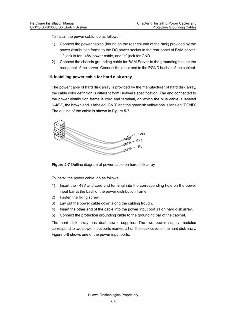
Hardware Installation Manual U-SYS SoftX3000 SoftSwitch System
Chapter 5 Installing Power Cables and Protection Grounding Cables
Huawei Technologies Proprietary
5-8
To install the power cable, do as follows:
1) Connect the power cables (bound on the rear column of the rack) provided by the power distribution frame to the DC power socket in the rear panel of BAM server. “–” jack is for –48V power cable, and “+” jack for GND.
2) Connect the chassis grounding cable for BAM Server to the grounding bolt on the rear panel of the server. Connect the other end to the PGND busbar of the cabinet.
III. Installing power cable for hard disk array
The power cable of hard disk array is provided by the manufacturer of hard disk array, the cable color definition is different from Huawei’s specification. The end connected to the power distribution frame is cord end terminal, on which the blue cable is labeled “–48V”, the brown end is labeled “GND” and the greenish yellow one is labeled “PGND”. The outline of the cable is shown in Figure 5-7.
Figure 5-7 Outline diagram of power cable on hard disk array
To install the power cable, do as follows:
1) Insert the –48V and cord end terminal into the corresponding hole on the power input bar at the back of the power distribution frame.
2) Fasten the fixing screw. 3) Lay out the power cable down along the cabling trough. 4) Insert the other end of the cable into the power input port J1 on hard disk array. 5) Connect the protection grounding cable to the grounding bar of the cabinet.
The hard disk array has dual power supplies. The two power supply modules correspond to two power input ports marked J1 on the back cover of the hard disk array. Figure 5-8 shows one of the power input ports.

Hardware Installation Manual U-SYS SoftX3000 SoftSwitch System
Chapter 5 Installing Power Cables and Protection Grounding Cables
Huawei Technologies Proprietary
5-9
Figure 5-8 Power Input interface on hard disk array
IV. Installing power cable for KVMS
The power cable for KVMS is made of 16 AWG UL1015 wires (with the core area about 1.3 mm2). One end to the power distribution frame has two cord end terminals and the other end has two OT terminals. The blue cable corresponds to –48V, and the black one corresponds to GND. Figure 5-9 shows its appearance.
Figure 5-9 Appearance of power cable for KVMS
To install the power cable, do as follows:
1) Insert the cord end terminals into the output connection holes marked “–48V” and “BGND” on the power distribution frame according to corresponding colors, and fasten the fastening screws.
2) Lay out the power cable downward along the cabling trough at the left side. 3) Insert the OT terminals into the wire post of the switcher according to the principle
“blue for –48V, black for RTN”, and fasten the cruciform screws, as shown in Figure 5-10.

Hardware Installation Manual U-SYS SoftX3000 SoftSwitch System
Chapter 5 Installing Power Cables and Protection Grounding Cables
Huawei Technologies Proprietary
5-10
Figure 5-10 Connection of power cable and protection grounding cable of KVMS
V. Installing power cable for LAN Switch
The power cable for LAN Switch is made of 16AWG UL1015 wires, both ends of which are cord end terminals. Figure 5-11 shows its appearance.
Figure 5-11 Appearance of LAN Switch power cable
The power input module of LAN Switch is located at the left-back and there is a plastic socket, which is similar to the output connection holes on power distribution frame. Besides, there is a power switch at the leftmost, as shown in Figure 5-12:
(1)
BGN
D-4
8--6
0
(2)
(1) Power switch (2) DC power input
Figure 5-12 Power switch on LAN Switch
To install the power cable, do as follows:
1) Insert one end into the output connection holes on the power distribution frame according to the cable labels, and fasten the fastening screws.

Hardware Installation Manual U-SYS SoftX3000 SoftSwitch System
Chapter 5 Installing Power Cables and Protection Grounding Cables
Huawei Technologies Proprietary
5-11
2) Insert the other end into the plastic socket at the back of the LAN Switch, and fasten the captive screws.
3) Lay out the cable along the inside of the mount angle on the left column. 4) Bind the redundant at the bundling bar nearby.
VI. Installing power cable for MRS
The MRS is configured in the MRS cabinet independently with dual power supplies. Figure 5-13 shows the appearance of its power cable.
Figure 5-13 Appearance of MRS power cable
Figure 5-14 shows the connection of the power cable for the MRS.

Hardware Installation Manual U-SYS SoftX3000 SoftSwitch System
Chapter 5 Installing Power Cables and Protection Grounding Cables
Huawei Technologies Proprietary
5-12
(1) Grounding bar (2) Power distribution frame (3) Blank filler panel (4) MRS frame
Figure 5-14 Connection of power cables in MRS cabinet

Hardware Installation Manual U-SYS SoftX3000 SoftSwitch System
Chapter 5 Installing Power Cables and Protection Grounding Cables
Huawei Technologies Proprietary
5-13
5.3.4 Installing Protection Grounding Cables for Internal Components
I. Installing protection grounding cable for service frame
The protection grounding cables for service frame are 10AWG green and yellow cables. To install them for service frame, use two protection grounding cables to connect the two grounding terminals on the back cover plate of fan box in service frame to the grounding bars at both sides of cabinet respectively.
II. Installing protection grounding cable for iGWB or BAM
The grounding cable for iGWB or BAM is 16AWG UL1015. Figure 5-15 shows the appearance of the cable.
Figure 5-15 Appearance of PGND cable for iGWB and BAM
To install the protection grounding cables for the iGWB and BAM, proceed as follows:
1) Connect the UT terminal to PGND terminal of the iGWB and BAM. 2) Connect the OT terminal to the grounding bar.
III. Installing protection grounding cable for KVMS
The protection grounding cable for KVMS is made of 14AWG wires (green and yellow, with core area about 2.1 mm2). The appearance of the protection grounding cable for the KVMS is similar to the one for the iGWB and BAM. Refer to Figure 5-15 for details.
To install the protection grounding cable, do as follows:
1) Connect the OT terminal to proper position on the grounding bar nearby. 2) Fix the OT terminal with screw. 3) Fix the UT terminal to PGND terminal of the KVMS.
IV. Installing protection grounding cables for LAN Switch
The grounding point for the LAN Switch is located on the back panel of the chassis, as shown in Figure 5-16.

Hardware Installation Manual U-SYS SoftX3000 SoftSwitch System
Chapter 5 Installing Power Cables and Protection Grounding Cables
Huawei Technologies Proprietary
5-14
(1)
SLOT2
(1) Grounding point
Figure 5-16 Grounding point LAN Switch shell
The protection grounding cable is delivered together with the LAN Switch. Proceed as follows to install the PGND cable for the LAN Switch:
One end is connected to the grounding pole on the back panel of the LAN Switch, and the other end is well grounded nearby.
V. Installing protection grounding cable for MRS
The grounding point of the MRS is located on the back panel of the chassis, as shown in Figure 5-17.
(1)
-48V GND -48V GND
(1) Grounding point
Figure 5-17 Grounding point of MRS
The protection grounding cable is green and yellow wire of 10AWG. Proceed as follows to install the PGND cable for MRS:
1) Connect one end of the PGND cable to the grounding pole on the back panel of the MRS.
2) Connect the other end to proper position on the grounding bar nearby.

Hardware Installation Manual U-SYS SoftX3000 SoftSwitch System
Chapter 5 Installing Power Cables and Protection Grounding Cables
Huawei Technologies Proprietary
5-15
5.3.5 Installing Protection Grounding Cables Between Cabinets
Note:
For the convenience of installing and binding other cables, the grounding bars of adjacent cabinets are interconnected after all cables of the equipment have been installed.
To install protection grounding cables between cabinets, use 10AWG cables (300 mm long) to connect the upper, middle, and lower parts of the grounding bars of adjacent cabinets, as shown in Figure 5-18.
5.3.6 Installing Power Cables and Protection Grounding Cables for Cabinets
I. Introduction to installing power cables for cabinets
There might be two cases when you install power cables and protection grounding cables to a cabinet, that is, if DC power distribution cabinet is provided together with the SoftX3000 equipment, and if only DC power switchboard is configured in the equipment room. For detailed information, see the contents later in this section.
II. Connecting cables from DC power distribution cabinet to SoftX3000 cabinet
Note:
Before connecting power cables and protection grounding cables, measure the distance between protection grounding bar and power distribution cabinet, and the distance between DC power distribution cabinet and connecting terminals of the power distribution frame in the cabinet. If a used cable is not long enough, stop your work and replace it with a new one. Do not splice cables by connectors or soldering. It is required to stick labels at both ends of a power cable where they are 30 mm away from the root of the cable.
Figure 5-18 shows the connection of power cables from the DC power distribution cabinet to the SoftX3000 cabinet.

Hardware Installation Manual U-SYS SoftX3000 SoftSwitch System
Chapter 5 Installing Power Cables and Protection Grounding Cables
Huawei Technologies Proprietary
5-16
-48V2
GND
PGND
-48V1 PGN
D
-48V1-48V2
BGN
D(1)
(2)
(3)
(4)
GND
PGN
D
-48V1-48V2
BGN
D
PGN
D
-48V1-48V2
BGN
D
(3) (3)
(1) To DC power switchboard (2) DC power distribution cabinet (3) SoftX3000 cabinet (4) Protection grounding bar in equipment
room
Figure 5-18 Connecting power cables and protection grounding cables between DC power distribution cabinet and SoftX3000 cabinet
The following describes how to connect power cables and protection grounding cables from DC power distribution cabinet to a SoftX3000 cabinet:
1) Insert the cord end terminals (as shown in Figure 5-19) of the two blue power cables into the connecting terminals marked “–48V1” and “–48V2” on the power distribution frame in the cabinet and fasten them.
2) Connect the other ends of the two blue cables to the corresponding output connectors marked “–48V1” and “–48V2” in the DC power distribution cabinet, for example, the “–48V1” and “–48V2” power cables in the third cabinet must be connected to the third output connectors of “–48V1” and “–48V2” in the DC power distribution cabinet.
Figure 5-19 Cord end terminal of power cable

Hardware Installation Manual U-SYS SoftX3000 SoftSwitch System
Chapter 5 Installing Power Cables and Protection Grounding Cables
Huawei Technologies Proprietary
5-17
3) Use the black BGND cables to connect the connecting terminals marked “BGND” on the power distribution frame of the cabinet, and the GND grounding bars in the DC power distribution cabinet.
4) Connect one end of the protection grounding cable (yellow or green and yellow) to the connecting terminal marked “PGND” in the power distribution frame of the cabinet, and connect the other end to the protection grounding bar in the equipment room.
For –48V1 and –48V2 connecting terminals, it is required to use the upper group first, and then the lower group. For each group, it is required to use the connecting terminals from left to right (viewed from the front side) one by one. The terminals for positive line bank and lightning protection ground are used sequentially from left to right.
Note:
In other cases when power cables are led from DC power distribution cabinet, (for example, to connect protection grounding cables for a terminal), reverse principle is applied, that is, the terminals are used from down to top and from right to left, to facilitate future expansion and connection.
If DC power distribution cabinet is not configured in the equipment room, do as follows:
1) Connect the power cables led from –48V1 and –48V2 connecting terminals of the SoftX3000 cabinet to –48 VDC negative line bank of DC switchboard (or DC power supply);
2) Connect the power cable led from GND connecting terminal of the SoftX3000 cabinet to –48 VDC positive line bank of DC switchboard (or DC power supply);
3) Connect the protection grounding cable led from the PGND connecting terminal of the SoftX3000 cabinet to the protection grounding bar nearby provided by the customer. The cable material must be the green and yellow plastic insulation copper core wire whose core area is the same as that of power cable.
III. Laying power cables and protection grounding cables at SoftX3000 sdie
When downward cabling is used, the steps to laying power cables and protection grounding cables at the SoftX3000 cabinet side are as follows:
1) Lead the power cables and protection grounding cables into the cabinet through rodent-proof net at the bottom of the cabinet.
2) Lay the power cables and protection grounding cables along the cabling troughs on the side columns of the cabinet until they reach the top of cabinet.
3) Connect the power cables and protection grounding cables to the corresponding connecting terminals in the power distribution frame.

Hardware Installation Manual U-SYS SoftX3000 SoftSwitch System
Chapter 5 Installing Power Cables and Protection Grounding Cables
Huawei Technologies Proprietary
5-18
When upward cabling is used, the steps to laying power cables and protection grounding cables at the SoftX3000 cabinet side are as follows:
1) Lay the power cables and protection grounding cables on the top of cabinet. 2) Connect the protection grounding cables to the grounding bolts. 3) Lead the protection grounding cables out from the grounding bolts. 4) Pass the power cables and protection grounding cables trough the cabling holes in
the top of the cabinet. 5) Connect the power cables and protection grounding cables to the corresponding
connecting terminals in the power distribution frame.
To lay the power and protection grounding cables, straight and even appearance is required, and different colors must be separated, and the cables must be bound every 200 mm.
After the power and protection grounding cables are laid out, it is required to cut the rubber cover to match the size of the left space of the cabling hole.
Note:
When power cables and protection grounding cable are laid outside cabinet, they must be bound separately. When cables are laid inside cabinet, power cables and protection grounding cable are bound separate from signal cables.
IV. Laying power and protection grounding cables in DC power distribution cabinet
To lay the power cables and protection grounding cables in the DC power distribution cabinet, do as follows:
1) Lead the power cables (settled according to colors) into DC power distribution cabinet through cabling holes in the top of the cabinet
2) Lay and bind the power cables along the side columns, until they reach corresponding bus bars.
3) Lay and bind them along the beam of the cabinet. Ensure that the cables are laid inside the cabinet with smooth and uncrossed appearance.
4) Add flat washers and spring washers to connect OT terminals to GND copper bus bar and –48V wire post.

Hardware Installation Manual U-SYS SoftX3000 SoftSwitch System
Chapter 5 Installing Power Cables and Protection Grounding Cables
Huawei Technologies Proprietary
5-19
Note:
When power cables and protection grounding cable are laid outside cabinet, they must be bound separately. When cables are laid inside cabinet, power cables and protection grounding cable are bound separate from signal cables.
It is required to keep proper redundancy for the cables, and to cut out the surplus parts. When you make an OT terminal for a cable, be sure to cover it with heat-shrinkable tube, solder it (soldering is not allowed when you make a cable with large core area), and shrink the heat-shrinkable tube.
5.4 Installing Power Bus Cables from DC Power Distribution Cabinet to DC Switchboard
5.4.1 Introduction to Power Bus Cables from DC Power Distribution Cabinet to DC Switchboard
Power bus cables are used to connect DC power distribution cabinet and DC switchboard.
Generally provided by the customer, a power bus cable in the power room includes –48 VDC cable (blue) and BGND cable (black). The specifications of power bus cables are determined according to the result of site survey.
Note:
The core area of power bus cable from DC switchboard to DC power distribution cabinet is designed according to the parameters such as loop length of the power bus cable, terminal load payload capacity for the engineering and design voltage drop.
If a large-core-area power cable is required, you can connect two or more power cables in parallel to meet the requirement. For example, if there are only 120 mm2 power cables, but a 240 mm2 power cable is required, you can use two 120 mm2 power cables in parallel connection as one power cable.
Refer to Appendix C Calculating Core Area of Power Bus Cable for the calculation of core area of power bus cables.

Hardware Installation Manual U-SYS SoftX3000 SoftSwitch System
Chapter 5 Installing Power Cables and Protection Grounding Cables
Huawei Technologies Proprietary
5-20
5.4.2 Connecting Power Bus Cables from DC Power Distribution Cabinet to DC Switchboard
Figure 5-20 shows the connection of the power bus cables for the auxiliary DC power distribution cabinet of the SoftX3000 cabinet. For detailed information on connecting power bus cables, refer to User Manual delivered with the DC power distribution cabinet.
(1) GND lead-in terminal block (2) –48V1 power lead-in terminal block
(3) –48V2 power lead-in terminal block (4) PGND lead-in terminal block (5) –48V1 output terminal block (6) –48V2 output terminal block (7) GND output terminal block (8) PGND output terminal block (9) GND lead-in terminal block for downward cabling of the system
Figure 5-20 Connecting terminals in DC power distribution cabinet
Two groups of primary power supplies are used for a DC power distribution cabinet, and there are five bus cables: one –48V1 bus cable, one –48V2 bus cable, two GND bus cables and one PGND bus cable.
The following describes how to connect the power bus cables between the DC power distribution cabinet and the DC switchboard:
1) Connect –48V1 bus bar in the DC power distribution cabinet to –48 VDC negative line bank in the active DC switchboard (or active DC power supply),

Hardware Installation Manual U-SYS SoftX3000 SoftSwitch System
Chapter 5 Installing Power Cables and Protection Grounding Cables
Huawei Technologies Proprietary
5-21
2) Connect –48V2 bus bar in the DC power distribution cabinet to –48 VDC negative line bank in the standby DC switchboard (or standby DC power supply).
3) Connect the GND bus bars in the DC power distribution cabinet to the –48 VDC positive line banks in the active and standby DC switchboards (or active and standby DC power supplies) respectively.
If there is only one power supply device, connect both of the –48V1 and –48V2 bus bars of the DC power distribution cabinet with the –48 VDC output terminals of the DC switchboard (or DC power supply).
Note:
The PGND grounding bar of the DC power distribution cabinet must be reliably connected to the protection grounding bar provided by the customer through grounding bus cable.
5.4.3 Making and Fixing OT Terminals
To make an OT terminal for a power bus cable or protection grounding cable at DC power distribution cabinet side, do as follows:
1) Cover the cable with a heat-shrinkable tube. 2) Solder (soldering is not allowed when you make a cable with large core area) or
press the OT terminal tightly. 3) Shrink the heat-shrinkable tube, and ensure that no bare wires or OT terminal
handle exist.
To fix an OT terminal at DC power distribution cabinet side, add flat washers and spring washers to make the terminal fixed firmly, and to ensure secure contact, as shown in Figure 5-21.
Note:
Proper redundancy for power bus cables can be kept at bending angles, but other surplus parts must be cut out. If the surplus parts are cut out, OT terminal must be remade.

Hardware Installation Manual U-SYS SoftX3000 SoftSwitch System
Chapter 5 Installing Power Cables and Protection Grounding Cables
Huawei Technologies Proprietary
5-22
(2)
(5)(6) (4)
(3)
(1)
(1) Cable (2) Heat-shrinkable tube (3) Nut (4) Spring washer (5) Flat washer (6) Connection bolt
Figure 5-21 Connecting OT terminal
5.4.4 Requirements for Installing OT Terminals
If it is necessary to install two or more cables on a wire post, install the OT terminals crosswise or back-to-back without being overlapped. If the OT terminals have to be overlapped, bend the terminals by 45 degree or 90 degree and install the biggest OT terminal at lower position. This rule is adaptable to all situations where OT terminals are installed. Figure 5-22 shows the overlapped OT terminals.

Hardware Installation Manual U-SYS SoftX3000 SoftSwitch System
Chapter 5 Installing Power Cables and Protection Grounding Cables
Huawei Technologies Proprietary
5-23
(4)
(5) (6)
(1)
(2)
(3) (3)
(2)
(1)
(2)
(3)
(1)
(2)(3)(1)
45°90°
(1)Flat washer (2)Nut (3) Spring washer (4) 45 degree or 90 degree of bending (5) Back-to-back installation (6) Cross installation
Figure 5-22 Installing two OT terminals
5.4.5 Requirements for Laying Cables Inside DC Power Distribution Cabinet
The requirements for laying cables inside DC power distribution cabinet are as follows:
The cables laid inside DC power distribution cabinet are smooth and not crossed, and the cables in different colors are bound separately.
Proper redundancy for cables is kept and the surplus parts are cut out. Both ends of a cable have labels made by Huawei Technologies and marked
corresponding serial number. The labels are stuck 30 mm away from the cable root.
The cables are bundled by different cable ties according to the actual conditions. The cable ties face the same direction after the cables are bundled, and the burrs of the cable ties must be sheared.
Figure 5-23 shows the DC power distribution cabinet when the cables are laid in upward cabling mode.

Hardware Installation Manual U-SYS SoftX3000 SoftSwitch System
Chapter 5 Installing Power Cables and Protection Grounding Cables
Huawei Technologies Proprietary
5-24
Figure 5-23 Upward cabling for DC power distribution cabinet

Hardware Installation Manual U-SYS SoftX3000 SoftSwitch System Chapter 6 Installing Signal Cables
Huawei Technologies Proprietary
6-1
Chapter 6 Installing Signal Cables
6.1 Introduction to the Chapter
This chapter contains the following sections:
Introduction to Signal Cables Requirements and Modes of Laying Signal Cables Installing Internal Signal Cables Installing External Signal Cables
6.2 Introduction to Signal Cables
6.2.1 Types of Signal Cables
The signal cables are divided into internal signal cables and external signal cables. Among the external signal cables, the clock cable, trunk cable and external network cable are optional depending on the actual hardware configuration.
The internal signal cables that need to be installed on site include:
Straight through network cable between LAN Switches Straight through network cable between iGWB/BAM and LAN Switch Straight through network cables between boards in service frame and LAN Switch FE signal cable between HSCI and SIUI Serial port cable between iGWB servers Data cable between iGWB server and hard disk array (only when iGWB uses IBM
server) Server/Switcher cable Serial port cable for monitoring power distribution frame Internal clock cable(optional)
The external signal cables include:
Trunk cable(optional) External clock cable(optional) External network cable
6.2.2 Connection of Internal Signal Cables
Figure 6-1 shows the method of connecting internal cables installed on site. Table 6-1 shows the relationships between numbers and names of internal cables.

Hardware Installation Manual U-SYS SoftX3000 SoftSwitch System Chapter 6 Installing Signal Cables
Huawei Technologies Proprietary
6-2
23
24
2M-A 2M-A
2M-B 2M-B
8k-B
8k-B
44 43
50
48
8k-A
8k-A
E1/T1 E1/T1
2M-A 2M-A
2M-B 2M-B
8k-A
8k-A
8k-B
8k-B
E1/T1 E1/T1
49
47
46 45
29
31 3230
23 24
414243 44 4
645
40
27
2539
26
28
4042
34 36 38
3941
33 35 37
3433
3635
3837
W8W9W10
KVMS
LAN Switch0
LAN Switch1
BAM
Standby iGWB
Active iGWB
W8
W9
W10
52
4748
4950
W2W3
(4)
(3)
(2)
(1)
(1) Power distribution frame (2) Expansion frame (3) Basic frame (4) Hard disk array
Figure 6-1 Connection of internal cables in integrated configuration cabinet
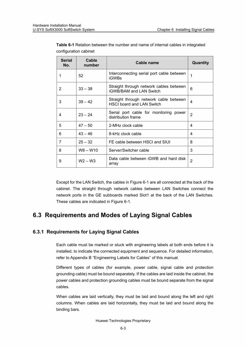
Hardware Installation Manual U-SYS SoftX3000 SoftSwitch System Chapter 6 Installing Signal Cables
Huawei Technologies Proprietary
6-3
Table 6-1 Relation between the number and name of internal cables in integrated configuration cabinet
Serial No.
Cable number Cable name Quantity
1 52 Interconnecting serial port cable between iGWBs 1
2 33 – 38 Straight through network cables between iGWB/BAM and LAN Switch 6
3 39 – 42 Straight through network cable between HSCI board and LAN Switch 4
4 23 – 24 Serial port cable for monitoring power distribution frame 2
5 47 – 50 2-MHz clock cable 4
6 43 – 46 8-kHz clock cable 4
7 25 – 32 FE cable between HSCI and SIUI 8
8 W8 – W10 Server/Switcher cable 3
9 W2 – W3 Data cable between iGWB and hard disk array 2
Except for the LAN Switch, the cables in Figure 6-1 are all connected at the back of the cabinet. The straight through network cables between LAN Switches connect the network ports in the GE subboards marked Slot1 at the back of the LAN Switches. These cables are indicated in Figure 6-1.
6.3 Requirements and Modes of Laying Signal Cables
6.3.1 Requirements for Laying Signal Cables
Each cable must be marked or stuck with engineering labels at both ends before it is installed, to indicate the connected equipment and sequence. For detailed information, refer to Appendix B “Engineering Labels for Cables” of this manual.
Different types of cables (for example, power cable, signal cable and protection grounding cable) must be bound separately. If the cables are laid inside the cabinet, the power cables and protection grounding cables must be bound separate from the signal cables.
When cables are laid vertically, they must be laid and bound along the left and right columns. When cables are laid horizontally, they must be laid and bound along the binding bars.

Hardware Installation Manual U-SYS SoftX3000 SoftSwitch System Chapter 6 Installing Signal Cables
Huawei Technologies Proprietary
6-4
If power cables and signal cables are laid in a groove, they must not be bound together, and a distance of at least 50 mm between them must be ensured.
Joint parts of connectors must be secure and in good contact.
Cables must be bound in order and with proper tightness.
6.3.2 Modes of Laying Signal Cables
There is one rectangle cabling holes at each of the four corners on the top of cabinet and of the four corners at the bottom of cabinet. All the cabling holes have rodent-proof nets. Figure 6-2 shows the positions of the four cabling holes on the top of as cabinet as indicated by arrows.

Hardware Installation Manual U-SYS SoftX3000 SoftSwitch System Chapter 6 Installing Signal Cables
Huawei Technologies Proprietary
6-5
Figure 6-2 External cabling holes on the cabinet
According to the actual conditions of the equipment room, the cables led in and out of cabinet can be laid through the cabling holes on the top or bottom of cabinet.
To lay the cables, lead the cables into the cabinet through the two back cabling holes on the top or bottom of the cabinet, and lay them along the side columns of the cabinet into corresponding cabling frame under each LAN Switch. Then, lay the cables through the cabling frames and insert them into corresponding sockets on the front panels of LAN Switches. Be sure to get the cables in order and fix them in the wire bushing.

Hardware Installation Manual U-SYS SoftX3000 SoftSwitch System Chapter 6 Installing Signal Cables
Huawei Technologies Proprietary
6-6
At the cabling holes, there is rodent-proof net, through which cables shall pass. The size of the cabling holes must be proper so that no space is left around the cables.
The external cables are laid through cabling trough or cabling rack. For the methods for installing cabling rack, refer to Appendix A “Installing Cabling Rack” in this manual.
6.4 Installing Internal Signal Cables
6.4.1 Installation Procedure
Figure 6-3 shows the procedure for installing the internal signal cables.

Hardware Installation Manual U-SYS SoftX3000 SoftSwitch System Chapter 6 Installing Signal Cables
Huawei Technologies Proprietary
6-7
Installing straight through network cable betweenLAN Switches
Installing straight through network cable betweeniGWB/BAM and LAN Switch
Installing straight through cable between board inservice frame and LAN Switch
Installing FE signal cable between HSCI and SIUI
Installing serial port cable between iGWB servers
Installing data cable between iGWB server andhard disk array
Installing Server/Switcher cable
Installing cable for monitoring power distributionframe
Installing internal clock cable (optional)
Power cable and protection grounding cableinstallation complete
Internal cableinstallation complete
Figure 6-3 Procedure for installing internal signal cables
6.4.2 Installing Straight Through Network Cable Between LAN Switches
The two S3528G LAN Switches are interconnected through three straight through cable, and they work in dual backup mode. The dual backup mode, which is adopted to ensure data security, means that the two LAN Switches detect each other's heartbeat signals.

Hardware Installation Manual U-SYS SoftX3000 SoftSwitch System Chapter 6 Installing Signal Cables
Huawei Technologies Proprietary
6-8
The three straight through cables respectively connects the FE interfaces 22, 23, and 24 of the two S3528G. Table 6-2 shows the connection mapping between the two LAN Switches.
Table 6-2 Connection mapping of straight through cables between the two LAN Switches
0#LAN Switch 1#LAN Switch
22 22
23 23
24 24
Before delivery, the FE interfaces 22, 23, and 24 of the two S3528G have been bound logically as three interfaces. This ensures the security and reliability. If you want to modify the settings of the two LAN Switches, refer to U-SYS SoftX3000 SoftSwitch System Part Replacement Guide for details.
6.4.3 Installing Straight Through Network Cable Between iGWB/BAM Server and LAN Switch
The integrated configuration cabinet has three servers: two iGWB servers and one BAM server. Each server uses two straight through network cables to connect with the active and standby LAN Switches. The upper network port is connected to LAN Switch 0, and the lower network port is connected to LAN Switch 1, as shown in Figure 6-1.
Because the ports of LAN Switches are arranged on the front panels, while the ports of the servers are arranged on the back panels of the servers, back cabling is required to lay the network cables which connect the servers and LAN Switches.
To install a pair of cable for a LAN Switch and a server, do as follows:
1) Insert the crystal connectors at one end of the network cables into the ports of the LAN Switches, and leave some surplus.
2) Lead the cables through the cabling frame under each LAN Switch to the back of the cabinet.
3) Separate the cables and lay them downward along the vertical cabling troughs at both sides.
4) Insert the crystal connectors at the other end into corresponding ports of a server, as shown in Figure 6-4.
The cable connection positions on the front panel of the LAN Switch depend on the port configuration scheme.

Hardware Installation Manual U-SYS SoftX3000 SoftSwitch System Chapter 6 Installing Signal Cables
Huawei Technologies Proprietary
6-9
Figure 6-4 Connection position of straight through network cable on server
Note:
The BAM and the emergency workstation connect the LAN Switch with straight through cables. In this way, the emergency workstation can back up the data from the BAM.
Connect two straight through cables with the emergency workstation and leave them disconnected from the LAN Switch when the BAM is normal. When the BAM is faulty, immediately connect the two cables with the active and standby core LAN Switches. Refer to Figure 8-1 in chapter 8 for the cable connection of the emergency workstation.
6.4.4 Installing Straight Through Network Cable Between LAN Switch and HSCI
The service frames in the SoftX3000 communicate with each other through LAN Switch and the service boards are connected to LAN Switch through network ports.
In the integrated configuration cabinet and service processing cabinet, each of the active and standby HSCIs in both basic frame and expansion frame has six 10/100Mbit/s network ports. The ports marked 10/100BT6 at the uppermost position of the active and standby HSCIs are connected to the active and standby LAN Switches respectively through straight through cables, implementing the communication between the service processing subsystem and BAM, and the interconnection between the service processing frames. The HSCI in slot 7 is connected to LAN Switch 1, and
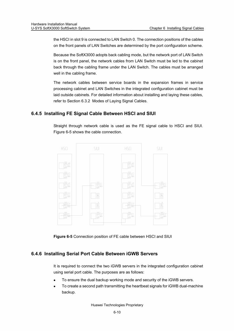
Hardware Installation Manual U-SYS SoftX3000 SoftSwitch System Chapter 6 Installing Signal Cables
Huawei Technologies Proprietary
6-10
the HSCI in slot 9 is connected to LAN Switch 0. The connection positions of the cables on the front panels of LAN Switches are determined by the port configuration scheme.
Because the SoftX3000 adopts back cabling mode, but the network port of LAN Switch is on the front panel, the network cables from LAN Switch must be led to the cabinet back through the cabling frame under the LAN Switch. The cables must be arranged well in the cabling frame.
The network cables between service boards in the expansion frames in service processing cabinet and LAN Switches in the integrated configuration cabinet must be laid outside cabinets. For detailed information about installing and laying these cables, refer to Section 6.3.2 Modes of Laying Signal Cables.
6.4.5 Installing FE Signal Cable Between HSCI and SIUI
Straight through network cable is used as the FE signal cable to HSCI and SIUI. Figure 6-5 shows the cable connection.
Figure 6-5 Connection position of FE cable between HSCI and SIUI
6.4.6 Installing Serial Port Cable Between iGWB Servers
It is required to connect the two iGWB servers in the integrated configuration cabinet using serial port cable. The purposes are as follows:
To ensure the dual backup working mode and security of the iGWB servers. To create a second path transmitting the heartbeat signals for iGWB dual-machine
backup.

Hardware Installation Manual U-SYS SoftX3000 SoftSwitch System Chapter 6 Installing Signal Cables
Huawei Technologies Proprietary
6-11
The connection port is the RS232 serial port at the right on the back panel of the iGWB server, as shown in Figure 6-4.
Note:
The master and slave iGWB servers are connected to the bill console or network management device through HUB. The external network cable connecting with the HUB also serves as the first heartbeat signal transfer path for the dual backup mode of iGWB.
6.4.7 Installing Data Cable Between iGWB Server and Hard Disk Array
Two pieces of SCSI data cables between iGWB servers and hard disk array are provided by the manufacturer of hard disk array. One end of the data cable connects with the SCSI slot on an iGWB server, and the other end connects to the SCSI socket on the upper part of hard disk array, as shown in Figure 6-6 and Figure 6-7.
Figure 6-6 Connection position of data signal cable on iGWB server
Figure 6-7 Connection position of data signal cable on hard disk array
6.4.8 Installing Server/Switcher Cable
A server/switcher cable is composed of keyboard cable, mouse cable and display cable, and it is delivered together with a server. At the KVM/LCD switcher side, these three
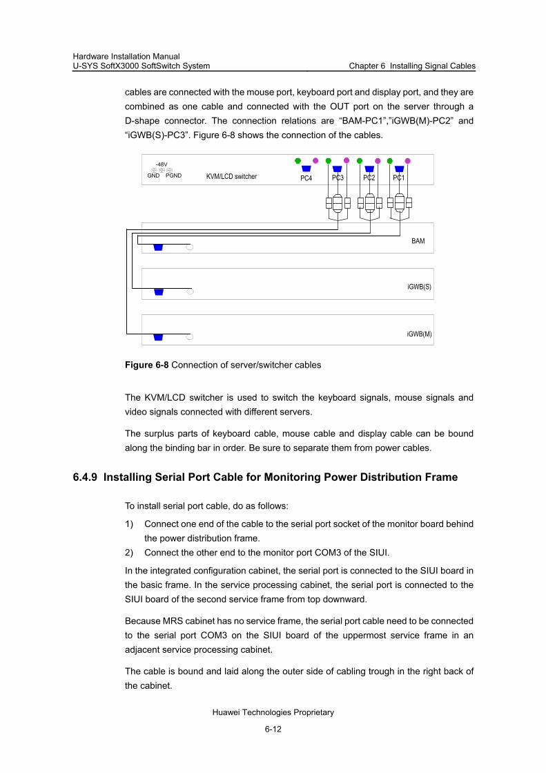
Hardware Installation Manual U-SYS SoftX3000 SoftSwitch System Chapter 6 Installing Signal Cables
Huawei Technologies Proprietary
6-12
cables are connected with the mouse port, keyboard port and display port, and they are combined as one cable and connected with the OUT port on the server through a D-shape connector. The connection relations are “BAM-PC1”,”iGWB(M)-PC2” and “iGWB(S)-PC3”. Figure 6-8 shows the connection of the cables.
iGWB(M)
iGWB(S)
BAM
PC3 PC2PC4 PC1GND PGND
-48V
KVM/LCD switcher
Figure 6-8 Connection of server/switcher cables
The KVM/LCD switcher is used to switch the keyboard signals, mouse signals and video signals connected with different servers.
The surplus parts of keyboard cable, mouse cable and display cable can be bound along the binding bar in order. Be sure to separate them from power cables.
6.4.9 Installing Serial Port Cable for Monitoring Power Distribution Frame
To install serial port cable, do as follows:
1) Connect one end of the cable to the serial port socket of the monitor board behind the power distribution frame.
2) Connect the other end to the monitor port COM3 of the SIUI.
In the integrated configuration cabinet, the serial port is connected to the SIUI board in the basic frame. In the service processing cabinet, the serial port is connected to the SIUI board of the second service frame from top downward.
Because MRS cabinet has no service frame, the serial port cable need to be connected to the serial port COM3 on the SIUI board of the uppermost service frame in an adjacent service processing cabinet.
The cable is bound and laid along the outer side of cabling trough in the right back of the cabinet.

Hardware Installation Manual U-SYS SoftX3000 SoftSwitch System Chapter 6 Installing Signal Cables
Huawei Technologies Proprietary
6-13
6.4.10 Installing Clock Cable Between Frames
I. Connecting Clock Cables
There are two types of internal clock cables: 2 MHz and 8 MHz.
Two CKII boards are connected to the active EPII board in the same frame through two 2 MHz clock cables. Figure 6-9 shows the connection of the 2 MHz clock cables.
Figure 6-9 Connection positions of 2 MHz clock cables
If more than one pair of EPII boards are configured, lead out two 2 MHz clock cables from another active EPII, and connect them to the interfaces LINE2 of the active and standby CKII boards.
The CKII board provides 16 channels of 8 kHz clock sources to other frames without clock boards through 8 kHz internal clock cables. The clock sources are connected to the EPII boards of such frames through cables, to realize the clock synchronization and hardware changeover between active and standby clock boards. Figure 6-10 shows the connection positions of 8 kHz clock cables.

Hardware Installation Manual U-SYS SoftX3000 SoftSwitch System Chapter 6 Installing Signal Cables
Huawei Technologies Proprietary
6-14
Figure 6-10 Connection positions of 8 kHz clock cables
II. Laying Clock Cables
The 2 MHz synchronous clock cables are used connect the CKIIs and EPIIs in the same frame, so they are laid and bound along the cabling trough of the frame.
To lay the 8 KHz clock cables, do as follows:
1) Lay the 8 KHz clock cables of the basic frame in the integrated configuration cabinet directly into the cabling trough of the frame.
2) Separate cables to both sides of the cabinet, and lay them upward to the EPIIs in the expansion frame of the cabinet.
3) Lay the clock cables to other cabinets downward along the cabinet. 4) Lead them out of the cabinet from the bottom, and then into the other two service
cabinets from the bottom. 5) Connect them to the EPIIs in the service frames.

Hardware Installation Manual U-SYS SoftX3000 SoftSwitch System Chapter 6 Installing Signal Cables
Huawei Technologies Proprietary
6-15
6.5 Installing External Signal Cables
6.5.1 Installation Procedure
Figure 6-11 shows the procedure for installing external signal cables.
Installing external clock cable (optional)
Installing trunk cable (optional)
Installing external network cable
External signal cables installationcomplete
Internal signal cables installationcomplete
Figure 6-11 Flow of installing external signal cable
Note:
In normal cases, the trunk cables and external clock cables are bound together. In this case, it is unimportant whether the trunk cables or the external clock cables are installed first.
6.5.2 Installing Trunk Cable Between SoftX3000 and DDF
I. Connecting Trunk Cables
The EPII boards are configured in active/standby mode, but only the active EPII board is connected to the trunk cable through its DB50 trunk socket, as shown in Figure 6-12.
To connect the trunk cables, do as follows:
1) Lead them out of the front panel of the EPII and down to the cabling trough of the cabinet.

Hardware Installation Manual U-SYS SoftX3000 SoftSwitch System Chapter 6 Installing Signal Cables
Huawei Technologies Proprietary
6-16
2) Lay them horizontally and then upward or downward along the left column of the cabinet.
3) Lead them out of the cabinet. 4) Lay them along the external cabling rack or cabling trough. 5) Connect them to the cable distribution rack in the equipment room.
(3)(2)(1)
EPII
(1) 50-pin socket (2) Main label (3) 8-E1 trunk cable
Figure 6-12 Connection position of trunk cable
II. Laying Trunk Cables
Before laying the trunk cables, measure the required length first. If the cables are not long enough during the actual cabling, select other proper cables instead. In special cases, splice cables for extension using dedicated coaxial cable connector, while soldering is prohibited.
In the equipment room with ESD-preventive floor, it is recommended to adopt downward cabling mode, which can ensure better appearance and easy cabling. If you use upward cabling mode, configure a cabling rack above the cabinet to lay the cables.
If you use downward cabling mode, do as follows:
1) Bend the cables at the bottom of the cabinet and reserve some surplus. Do not tighten the cables at the bottom of the cabinet when leading them out.
2) Lead them into the cabinet, and lay them along both sides of the cabinet. 3) Distribute them to the frames one by one. Other cabling positions or directions are
not allowed.
If you use upward cabling mode, do as follows:
1) Bend the cables at the top of the cabinet and reserve some surplus.

Hardware Installation Manual U-SYS SoftX3000 SoftSwitch System Chapter 6 Installing Signal Cables
Huawei Technologies Proprietary
6-17
2) If cabling ladder is used, lay the cables by the side of the ladder instead of between the ladder rungs. If the distance between the cabling ladder and the cabling trough on the top of the cabinet is within 0.8 m, lay the cables directly on the cabling trough; if the distance between the cabling ladder and the cabling trough on the top of the cabinet is more than 0.8 m, use downward cabling ladder.
3) Fix the cables on the downward cabling ladder, and do not pull the cables too tight.
6.5.3 Installing Clock Cable Between SoftX3000 and BITS
I. Connecting Clock Cables
According to different signal types, the 75 ohm coaxial cables transmitting BITS clock signals are connected with the corresponding SMB connectors BITS1 and BITS2 of the CKII boards in the basic frame, as shown in Figure 6-13.
Figure 6-13 Connection of external clock cable
At the BITS device side, the connection positions are:
“ER1” and “ER2” of “2M bit/s-IN” when the synchronous signal is 2 Mbit/s signal. Two synchronous signals are required at the same time and used in active/standby mode.
“2MR1” and “2MR2” when the synchronous signal is 2 MHz signal. Two synchronous signals are required at the same time and used in active/standby mode.

Hardware Installation Manual U-SYS SoftX3000 SoftSwitch System Chapter 6 Installing Signal Cables
Huawei Technologies Proprietary
6-18
II. Laying Clock Cables
To lay external clock cables, bind them together with trunk cables with the same cabling method for trunk cables.
6.5.4 Installing External Network Cables
I. Introduction to External Network Cables
The external network cables are used to connect the SoftX3000 with external network devices, and the external network ports in the SoftX3000 are provided by the corresponding back interface boards.
The media resource server (MRS) is also connected to the SoftX3000 through external networking devices. The active and standby media resource interface boards (MRIAs), media processor cards (MPCs) and shelf control cards (SCCs) are connected to the external routers or LAN Switches through the external network cables.
II. Connecting External Network Cables
The connecting positions of external network cables depend on the specific device connected with the SoftX3000. Take the connection between the SoftX3000 and IAD for example, the IAD is generally installed inside residential community or enterprise network, and it connects to the SoftX3000 through router or LAN Switch. One end of external network cable is connected to 10/100Mbit/s Ethernet ports on IFMI board in the SoftX3000, and the other end is connected with router or LAN Switch. The specific connection positions are determined by the port configuration scheme.
When the IAD is connected to the MRIA board of the SoftX3000 through external networking devices, the network cable is connected to the middle network port in the MRIA board.
III. Cabling
To lay external network cables, bind them together with trunk cables, with the same cabling method as the trunk cables.

Hardware Installation Manual U-SYS SoftX3000 SoftSwitch System Chapter 7 Installing Cabinet Fittings
Huawei Technologies Proprietary
7-1
Chapter 7 Installing Cabinet Fittings
7.1 Introduction to the Chapter
This chapter contains the following sections:
Installing ESD-Preventive Floor Holders and Recovering Floor Installing Door Lintels Installing Cabinet Side Panels Installing Front and Back Doors Installing Protection Grounding Cable for Cabinet Doors
7.2 Installing ESD-Preventive Floor Holders and Recovering Floor
7.2.1 Installing ESD-Preventive Floor Holders
The floor holder-slide rail assemblies are used to support ESD-preventive floor around the cabinet. The assemblies include front floor holder, back floor holder, and side floor holder. Front and back floor holders are fixed on the holder fixing components, and side floor holders are fixed on the supports at both ends of a cabinet row.
To install the floor holders, do as follows:
1) Use M12 bolts, spring washers, and flat washers to fix the front and back floor holders of each cabinet onto the holder fixing components.
2) Insert M12x30 bolts through the bolt holes of side floor folders and front and back floor folders to fix the side floor holders onto the supports at both ends of a cabinet row, as shown in Figure 7-1.

Hardware Installation Manual U-SYS SoftX3000 SoftSwitch System Chapter 7 Installing Cabinet Fittings
Huawei Technologies Proprietary
7-2
(1) Cabinet (2) Slide rail (3) Support (4) Bolt M12x30 (5) Spring washer 12 (6) Flat washer 12 (7) Front floor holder (8) Holder fixing component (9) Side floor holder
Figure 7-1 Fixing floor holders and slide rails
7.2.2 Adjusting Holder Height
To adjust the height of a floor holder, do as follows:
1) Loosen the bolts M12 in the floor holder. 2) Adjust the height of the floor holder to make its upper plane on the same height as
the lower plane of the ESD-preventive floor. 3) Secure the bolts M12.
7.2.3 Cutting and Recovering ESD-Preventive Floor
In this step, cut the ESD-preventive floor around the cabinet to match the border of the cabinet according to actual conditions on site and then recover the floor.
7.3 Installing Door Lintels
Each cabinet has four door lintels, which are installed on the upper and lower enclosure frames at the front and back of the cabinet.
To install door lintels, do as follows:

Hardware Installation Manual U-SYS SoftX3000 SoftSwitch System Chapter 7 Installing Cabinet Fittings
Huawei Technologies Proprietary
7-3
1) Align the door lintels with the mount brackets on the upper and lower enclosure frames.
2) Put the hooks of the door lintels into the slots of the mount brackets. 3) Use four M3 countersunk screws to fasten the door lintels, as shown in Figure 7-2.
Figure 7-3 shows the cabinet with door lintels.
Buckle
Rack
M3 countersunk screw
Door lintel
Mount bracket trough
Figure 7-2 Installation of door lintel
Figure 7-3 Cabinet with door lintels

Hardware Installation Manual U-SYS SoftX3000 SoftSwitch System Chapter 7 Installing Cabinet Fittings
Huawei Technologies Proprietary
7-4
7.4 Installing Cabinet Side Panels
A cabinet row has four side panels at both ends. Each end has two side panels are installed on the flat column of the cabinet.
To install the side panels, do as follows:
1) Loosen the clamping pole on the flat column. 2) Make the slot of a side panel onto the clamping pole downward, and buckle the
side panel into the open slot of the mount bracket. 3) Align the installation holes and secure the two M6 countersunk screws, as shown
in Figure 7-4.
Clamping boltSide panelfixing slot
Countersunk screw
Figure 7-4 Installation of side panel
7.5 Installing Front and Back Doors
A front door is composed of left door panel and right door panel, the same as the back door. Before installing the front and back doors, it is required to complete the installation of all frames, internal components, and circuit boards, as well as the connection of cables. The front and back doors must not be installed until all other hardware devices are installed completely.
Figure 7-5 shows the installation of the front and back doors. The installation procedure is as follows:

Hardware Installation Manual U-SYS SoftX3000 SoftSwitch System Chapter 7 Installing Cabinet Fittings
Huawei Technologies Proprietary
7-5
1) Align the lower pin of a door panel with the pin hole on the lower enclosure frame of the cabinet to install the lower border of the door panel.
2) Pull down the shuffle pin at the upside of the door, and align the hole for the pin on the door panel with the pin hole on the upper enclosure frame.
3) Release the shuffle pin to let the shuffle pin return to the original position by the spring.
The door panel is installed on the cabinet.
A
A
(1)
(2)
(1) Direction A: Align the lower pin of the door with the pin hole on the lower enclosure frame of the cabinet to install the lower border of the door. (2) Pull down the shuffle pin, align hole for the shuffle pin on the door panel with the pin hole on the upper enclosure frame. Then release the shuffle pin, and the shuffle pin returns to the original position, thus the door is installed on the cabinet.
Figure 7-5 Installation of front and back doors

Hardware Installation Manual U-SYS SoftX3000 SoftSwitch System Chapter 7 Installing Cabinet Fittings
Huawei Technologies Proprietary
7-6
Note:
The shuffle pins have been installed on the doors before delivery. After the front and back doors and side panels are installed, it is required to install
protection grounding cables at the positions of lower pins to ensure reliable grounding for the cabinet. For the specific installation method, see Section 5.3.4 in Chapter 5 "Installing Power Cables and Protection Grounding Cables" in this manual.
After the front doors are installed, stick the product brand in the concave on the upper part of front door.
7.6 Installing Protection Grounding Cable for Cabinet Doors
After the side panels, front door, and back doors are installed, it is required to use protection grounding cables to connect the grounding points on the door panels and the grounding bolt on the cabinet base, as shown in Figure 7-6.
(2)
(1)
(3)
(5)
(4)
(6)
(7)
(8)
(9)
(10)
(1) Front or back door (2) Side panel (3)Cabinet base (4) Grounding point of base (5) Grounding bar on side column (6) Grounding point on side pane (7) Grounding point on front or back door (8) Protection grounding cable for cabinet base (9) Protection grounding cable for side panel (10) Protection cable for front/back door
Figure 7-6 Downward cabling of protection grounding cable of cabinet

Hardware Installation Manual U-SYS SoftX3000 SoftSwitch System Chapter 7 Installing Cabinet Fittings
Huawei Technologies Proprietary
7-7
There are four protection grounding cables for side panels under the cabinet, and they are used to connect the grounding points on the side panels and the grounding points of the cabinet base. Meanwhile, there are four protection grounding cables for front and back doors under the cabinet, used to connect the grounding points on the front and back doors and the grounding points on the cabinet base. The protection grounding cables for cabinet doors are installed after the side cabinet doors are installed.

Hardware Installation Manual U-SYS SoftX3000 SoftSwitch System Chapter 8 Installing Peripherals
Huawei Technologies Proprietary
8-1
Chapter 8 Installing Peripherals
8.1 Introduction to the Chapter
This chapter contains the following sections:
Connecting to Terminal Equipment Connecting to Alarm Devices Grounding Requirements of Terminal Equipment Laying Cables for Terminal Equipment
8.2 Connecting to Terminal Equipment
Generally, the SoftX3000 is connected to multiple computer terminals (workstations), which are used as operation and maintenance terminal, billing terminal and alarm terminal respectively. Each terminal is connected to the BAM server by network cables. Besides, the SoftX3000 can be connected to remote maintenance terminals through Modem. Figure 8-1 shows the connection of terminal systems.
NI 3
NI 2
SP 1NI 0NI 1
SP 2
NI 3
NI 2
NI 0NI 1
Alarmbox
Remoteclient
External LAN Switch
LAN Switch 1
LAN Switch 0
BAM
Client
Emergencyworkstation
PSTN
ModemModem
Figure 8-1 Schematic diagram of the terminal system connection

Hardware Installation Manual U-SYS SoftX3000 SoftSwitch System Chapter 8 Installing Peripherals
Huawei Technologies Proprietary
8-2
When the BAM server works normally, it is not required to connect the two cables indicated by the dotted lines in Figure 8-1 to the LAN Switches. Once BAM server fails, use these two cables to connect the emergency workstation with the active and standby LAN Switches, and make the emergency workstation take over the BAM server.
Note:
The emergency workstation communicates with the alarm box through the program convert.exe after they are connected.
The SoftX3000 also enables remote access mode through iWEB remote maintenance terminal over Internet. Compared with the traditional Modem dial-up mode, the iWEB mode is more efficient in remote maintenance, data encryption and ciphered transmission, thus ensuring the security of the equipment.
8.3 Connecting to Alarm Devices
Figure 8-2 shows the composition and connection of alarm system of the SoftX3000. The alarm box is connected to alarm clients through serial ports.
Environmentalarm
Power alarm
Collectedalarm
ALUI WS Alarmbox
10 Mbit/s 10Mbit/s RS232SMUI BAM
Figure 8-2 Composition of alarm system
The universal alarm box adopts box structure, with advanced technology, high operability, maintainability and security. Figure 8-3 shows the appearance of the alarm box.

Hardware Installation Manual U-SYS SoftX3000 SoftSwitch System Chapter 8 Installing Peripherals
Huawei Technologies Proprietary
8-3
Figure 8-3 Appearance of alarm box
For detailed information about alarm box installation and cable connection, refer to Universal Alarm Box User Manual delivered with the alarm box.
8.4 Grounding Requirements of Terminal Equipment
The terminals are generally powered by 200 VAC. The power supply system must have a protection grounding end, and use the 3-core plug and socket.
The cable that connects the terminal equipment with the SoftX3000 can be the following:
RJ45 network cable RS232 serial port cable RS422 serial port cable
Connect the protection grounding cables with the same protection grounding bar of the SoftX3000 cabinet. The cross-sectional area should be more than equal to 4 mm2.
8.5 Laying Cables for Terminal Equipment
The alarm box, Hub, Modem and other terminals (workstations) are generally installed in the maintenance room. The modes of cabling and connecting cables for BAM and iGWB servers and Hub are similar to those for cabling and connecting external clock cables and trunk cables. It is required to lead network cables into the maintenance room through cabling trough or cabling rack. The power cables of terminals, signal

Hardware Installation Manual U-SYS SoftX3000 SoftSwitch System Chapter 8 Installing Peripherals
Huawei Technologies Proprietary
8-4
cables of monitors, and network cables of Hub must be laid in order and bound separately. To ensure the safety of both personnel and equipment, the power system must be reliably grounded.

Hardware Installation Manual U-SYS SoftX3000 SoftSwitch System Chapter 9 Hardware Installation Check
Huawei Technologies Proprietary
9-1
Chapter 9 Hardware Installation Check
9.1 Introduction to the Chapter
After hardware installation, it is necessary to check the hardware installation quality before subsequent software installation and system commissioning.
This chapter contains the following sections:
Checking Appearance of Hardware Components Checking Electrical Performance
9.2 Checking Appearance of Hardware Components
The appearance check is to review the whole installation procedures. The check items cover cabinets, cable distribution, connectors, sockets, labels and on-site environment, which are described below.
9.2.1 Checking Cabinets
The cabinet check covers the following aspects:
The cabinets in a row are in order, and either front or back plane of the cabinets is smooth.
All bolts are screwed tightly. All bolts have flat washers and spring washers, and they are fixed in correct direction.
Components and wires of the cabinets are complete and in good condition. All labels are correct, clear and complete.
There are no surplus cable ties, stubs or other sundries in the cabinets. The front and back doors and side panels are clean without defilement or handprint.
After all cables are laid, the small cover plates on both the top and bottom of cabinets cover corresponding cabling holes, thus prevent animals or dust from entry.
9.2.2 Checking Cable Distribution
I. Checking power cables and protection grounding cables
The check items include:
The power cables and protection grounding cables from the DC power distribution cabinet to power distribution frames in the cabinets are connected securely.
Hardware Installation Manual U-SYS SoftX3000 SoftSwitch System Chapter 9 Hardware Installation Check
Huawei Technologies Proprietary
9-2
The power cables and protection grounding cables from power distribution frames to network equipment are connected securely, and the protection grounding cables of all network equipment are connected securely.
Grounding polarities are correct and their contacts are good. The power cables and protection grounding cables are not laid together with signal
cables.
II. Checking network cables and clock cables in cabinet
The check items include:
The cable connections are correct and firm. The cable ties are in correct positions and are spaced properly. The cable ties are not overlapped and there are no sharp ends.
III. Checking trunk cables, clock cables, and network cables outside cabinet
The check items include:
The cables are not stretched at turnings. The cabling route is consistent with related specifications and the cable ties are
spaced properly. The cabling is straight and smooth, there is no cable crossover in the cabinet, and
cables outside the cabinet are bundled according to different cabinets they are connected to.
The cables in cabling troughs and cabling ladders are orderly arranged and all the cables are bundled without damage in the coating.
Redundant cables are left for future use and the cable ties have no sharp ends or overlaps.
9.2.3 Checking Connectors and Sockets
I. Checking connectors
The latches of cable connectors are tightly locked, and the coaxial cable connectors are fastened tightly.
II. Checking sockets
The sockets include trunk cable sockets, network cable sockets and HEADER sockets for all backplanes. There is no lack of pins or short circuit resulting from bent pins.

Hardware Installation Manual U-SYS SoftX3000 SoftSwitch System Chapter 9 Hardware Installation Check
Huawei Technologies Proprietary
9-3
9.2.4 Checking Labels and Equipment Room Environment
I. Checking cable labels
All labels are clean, tidy and in correct positions, and the marks are clear.
II. Checking environment of equipment room
There are no such sundries as cable ties, stubs and dryer bags left below the cabling trough, cabinets and movable floor around the cabinet.
There are no useless objects in the equipment room and all the necessities are neatly arranged in the room.
The workbench and movable floor are clean and tidy.
Perform electrical check after completing appearance check.
9.3 Checking Electrical Performance
9.3.1 Introduction to Electrical Performance Check
The electrical performance check must be performed strictly following the checking steps determined by the power supply relations. That is, first check the power supply to the cabinet, then check the power supplies to the frames, and finally check the power supplies to boards.
9.3.2 Introduction to Power Switches in Power Distribution Frame
Figure 9-1 shows the appearance of the front panel of the power distribution frame.

Hardware Installation Manual U-SYS SoftX3000 SoftSwitch System Chapter 9 Hardware Installation Check
Huawei Technologies Proprietary
9-4
(1) Running indicator (2) Alarm indicator (3) Alarm sound switch (4) – (6) –48V1 output switches (7) – (9) –48V2 output switches (10) Lightning protection unit panel
Figure 9-1 Front panel of power distribution frame
There are two indicators on the front panel of the power distribution frame, and their meanings are shown in Table 9-1.
Table 9-1 Meanings of indicators
Indicator Identifier Color Status Meaning
Flashing frequency: 0.5 Hz
There is power in, and the power distribution frame works normally
Flashing frequency: 4 Hz
The communication between the power distribution frame and the SMUI is abnormal. The power distribution frame does not work normally.
Running indicator RUN Green
Always off
There is no power in, or the power distribution frame comes across fault.
Always on or fast flashing
There is fault occurring to the power distribution frame. Alarm
indicator ALM Red
Always off There is no fault.
The alarm sound switch on the front panel is used to select whether to listen to the alarm sound for the power distribution frame. If the switch is “ON”, there will be alarm

Hardware Installation Manual U-SYS SoftX3000 SoftSwitch System Chapter 9 Hardware Installation Check
Huawei Technologies Proprietary
9-5
sound in case of fault in the power distribution frame. If the switch is “OFF”, there will be no alarm sound even when there is fault occurring to the power distribution frame.
Note:
To make a full check on the monitoring function of the power distribution frame, set the MONITOR ALARM to “ON” when performing electrical check to the equipment.
9.3.3 Introduction to Power Switches in MRS
There are two power switches on the MRS chassis, located at the upper right of the front panel and marked Feed A and Feed B. They respectively correspond to –48 VDC input A and input B.
There is no independent power switch on other service frame, whose input power supply is controlled by the corresponding switch in the power distribution frame.
9.3.4 Checking Power Supply of Cabinets
The check on power supply for cabinets is to see whether there is short circuit in all output power lines from the DC power distribution frame, whether the input DC voltage to the SoftX3000 cabinets is normal and whether the visual and audible alarm function of the frames in all cabinets is normal. The check steps are described as follows:
1) Shut down the input power supply of the DC power distribution frame, set the multimeter to ohm range and check the resistance between the output power supplies and between working grounding line (GND) and protection grounding line (PGND) of the DC power distribution frame. There is no short circuit between the output power supplies.
2) Confirm that all the switches in the power distribution frame on the cabinet top are turned off, and then turn on the switch of the DC power distribution cabinet. In the case of no load, use the multimeter to check whether the output power supply is within the allowed voltage range (–57V to –40V). At this time, red “ALM” indicator on the distribution box must flash and the buzzer will give off audible alarm upon setting the ALARM switch to “ON”.
If any of the above items does not meet the requirement, find out the reason and perform troubleshooting before the next step.

Hardware Installation Manual U-SYS SoftX3000 SoftSwitch System Chapter 9 Hardware Installation Check
Huawei Technologies Proprietary
9-6
9.3.5 Checking Power Supply of Frames
The check on power supply for frames is to set whether there is short circuit in all output power lines from the power distribution frame of the cabinet, and whether the input DC voltage to the intra-cabinet components is normal. The check steps are as follows:
1) Pull out all boards from the backplanes in the cabinet, and set all the switches of the distribution box on the cabinet top to position “ON”. At this time, there is no power alarm or audible alarm. The green “RUN” indicator flashes and the red “ALM” indicator does not light.
2) Check –48 VDC power supply, and the voltage, There is –48 VDC power supply to all the components, service frames and other devices, and their voltage is within the correct range (–57 V to –40 V).
If any of the above items does not meet the requirement, find out the reason and perform troubleshooting before the next step.
9.3.6 Performing Board Power-On Test
The working status of a board powered on can be known from the indicators on the board front panel. For the meanings of indicators, refer to U-SYS SoftX3000 SoftSwitch System Technical Manual Architecture and Principle.
The check steps are as follows:
1) Input and output cables of –48 VDC power supply are correctly connected and the connection cables are firm.
2) Set all the switches on power distribution frame to “OFF”. Insert the power boards in the frames, and then turn on the switches on the power distribution frame. The power boards and the fans in frames work normally.
3) Set all the switches on the power distribution frame to “OFF” once again, then insert the boards into the slots on the backplanes and fasten the front panels of the boards.
4) Set the power switches on the power distribution frame to “ON”. At this time, all board indicators are normal. If the indicators of all boards in a frame do not light after the power switches are turned on, it indicates that there is no –48 VDC input or there is connection error at the input terminals. If the power switch jumps upon being closed, it means there would be short circuit or error of connection of the output terminals (short circuit).

Hardware Installation Manual U-SYS SoftX3000 SoftSwitch System Appendjx A Installing Cabling Rack
Huawei Technologies Proprietary
A-1
Appendjx A Installing Cabling Rack
A.1 Introduction to the Appendix
This appendix contains the following sections:
Introduction to Cabling Rack Installing Cabling Rack
A.2 Introduction to Cabling Rack
A.2.1 Functions of Cabling Rack
When upward cabling mode is used, it is required to install cabling rack in equipment room to lay cables, to reinforce cabinet connections and to enhance shockproof performance.
A.2.2 Components of Cabling Rack
Figure A-1 shows the channel-section steel.
Figure A-1 Channel-section steel
Figure A-2 shows the channel-section connecting piece.
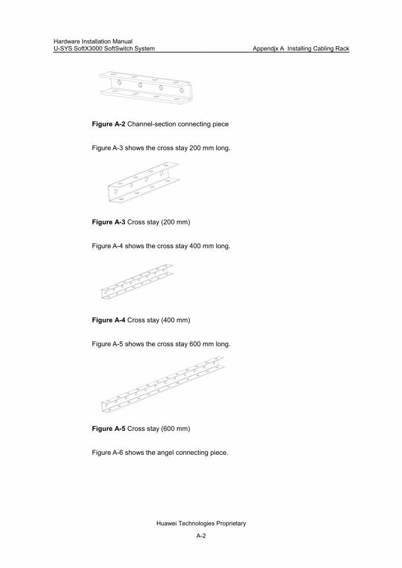
Hardware Installation Manual U-SYS SoftX3000 SoftSwitch System Appendjx A Installing Cabling Rack
Huawei Technologies Proprietary
A-2
Figure A-2 Channel-section connecting piece
Figure A-3 shows the cross stay 200 mm long.
Figure A-3 Cross stay (200 mm)
Figure A-4 shows the cross stay 400 mm long.
Figure A-4 Cross stay (400 mm)
Figure A-5 shows the cross stay 600 mm long.
Figure A-5 Cross stay (600 mm)
Figure A-6 shows the angel connecting piece.

Hardware Installation Manual U-SYS SoftX3000 SoftSwitch System Appendjx A Installing Cabling Rack
Huawei Technologies Proprietary
A-3
Figure A-6 Angle connecting piece
Figure A-7 shows the cable-trough clip.
Figure A-7 Cable-through clip
Figure A-8 shows the triangular support for 200 mm-wide cabling ladder.
Figure A-8 Triangular support (for 200 mm-wide cabling ladder)
Figure A-9 shows the triangular support for 400 mm-wide cabling ladder.

Hardware Installation Manual U-SYS SoftX3000 SoftSwitch System Appendjx A Installing Cabling Rack
Huawei Technologies Proprietary
A-4
Figure A-9 Triangular support (for 400 mm-wide cabling ladder)
Figure A-10 shows the triangular support for 600 mm-wide cabling ladder.
Figure A-10 Triangular support (for 600 mm-wide cabling ladder)
Figure A-11 shows the connecting clip for cabling trough.
Figure A-11 Connecting clip for cabling trough
Figure A-12 shows the fixing clip for cabling trough.

Hardware Installation Manual U-SYS SoftX3000 SoftSwitch System Appendjx A Installing Cabling Rack
Huawei Technologies Proprietary
A-5
Figure A-12 Fixing clip for cabling trough
Figure A-13 shows the cabling trough 200 mm long.
Figure A-13 Cabling trough (200 mm)
Figure A-14 shows the cabling trough 400 mm long.
Figure A-14 Cabling trough (400 mm)
Figure A-15 shows the insulating washer.
Figure A-15 Insulating washer

Hardware Installation Manual U-SYS SoftX3000 SoftSwitch System Appendjx A Installing Cabling Rack
Huawei Technologies Proprietary
A-6
Figure A-16 shows the insulating plate.
Figure A-16 Insulating plate
Figure A-17 shows the end cover.
Figure A-17 End cover
Figure A-18 shows bolt B (M8 x 20).
Figure A-18 Bolt B (M8 x 20)
Figure A-19 shows the movable cable bushing.
Figure A-19 Movable cable bushing

Hardware Installation Manual U-SYS SoftX3000 SoftSwitch System Appendjx A Installing Cabling Rack
Huawei Technologies Proprietary
A-7
A.2.3 Installation Modes
The cabling rack can be installed in four different modes:
Install a suspender on the ceiling to hang the cabling rack (hereinafter referred to as the “suspension mounting mode”).
Install a bracket on the ground to support the cabling rack (hereinafter, referred to as the “ground supporting mode”).
When the cabling rack is placed against the wall, install a triangular support on the wall to support the cabling rack.
When the cabling rack passes over the cabinet, install a shockproof support or a ladder on the cabinet to support the cabling rack.
A.2.4 Cabling Rack Specifications
Cabling rack is made of cabling ladder, and cabling trough which is optional component.
The cabling ladder and the cabling trough have the following specifications:
200mm-wide cabling ladder matches the 200mm-wide cabling trough; 400mm-wide cabling ladder matches the 400mm-wide cabling trough; 600mm-wide cabling ladder matches the 200mm +400mm-wide cabling trough.
It is recommended to use 400mm-wide cabling ladder over the cabinet, and not to use cabling trough, to facilitate cabling and to improve the heat dissipation of the system.
A.3 Installing Cabling Rack
A.3.1 Installation Procedure
Caution:
The cabling rack must be insulated from the floor, ceiling and walls.
Figure A-20 shows the procedure of installing cabling rack.

Hardware Installation Manual U-SYS SoftX3000 SoftSwitch System Appendjx A Installing Cabling Rack
Huawei Technologies Proprietary
A-8
Start
Mart drilling position
Secure the cablingladder (on ground,
rooftop, or wall)
Install accessoriesincluding cable-
through rack, cablebaffle ring, end cover,and protective cable
sheathing
Install and securecabling trough
Assemble cablingladder
Check drilling position
Drill the hole Φ8for 60mm
Install cablingtrough
End
Y
N
Figure A-20 Procedure of installing cabling rack
A.3.2 Assembling Cabling Ladder
The cabling ladder uses channel-section steel and cross stays for form its framework. .The channel-section steel functions as the vertical beams of the cabling ladder and the cross stays function as the horizontal beams. To assemble a cabling ladder, use fastener to connect the cross stays with the channel-section steel. The spacing between two cross stays is 250 mm. Because the spacing between holes in the channel-section steel is 50 mm, install one cross stay every five trough holes. When the assembled cabling ladder is used for horizontal installation, the bolt head of the cabling ladder should face downward to ensure that there is no protrusion on the ladder surface

Hardware Installation Manual U-SYS SoftX3000 SoftSwitch System Appendjx A Installing Cabling Rack
Huawei Technologies Proprietary
A-9
and to facilitate the installation of cabling trough. Figure A-21 shows the basic structure of cabling ladder.
(1) Fastener (2) Cross stay (3) Channel-section steel
Figure A-21 Basic structure of a cabling ladder
If a longer cabling ladder is required, you can join several cabling ladders in an “end to end” fashion. The channel-section connecting piece is used to connect ladders, as shown in Figure A-22. If the length of a cabling ladder is not an integral multiple of 2.5 m, cut off the remaining part. Use brush the paint the cross section to ensure protection against corrosion and to provide aesthetic look for the ladder.
(1) Channel-section steel (2) Channel-section connecting piece
Figure A-22 Connections between two cabling ladders
A.3.3 Connecting and Installing Cabling Troughs
Because cabling trough is cone-shaped, you can insert the smaller end of a cabling trough to the bigger end of another. The depth of inserted part is 250 mm. When

Hardware Installation Manual U-SYS SoftX3000 SoftSwitch System Appendjx A Installing Cabling Rack
Huawei Technologies Proprietary
A-10
200mm-wide or 400mm-wide cabling trough is used, directly place the cabling trough on cabling ladder, and secure the cabling trough on the cabling ladder with fixing clips. For each segment of the cabling trough, four such clips are used and they should be symmetrical at both sides. Figure A-23 shows the connection of cabling troughs.
(1) Cabling trough (2) Fixing clip of the cabling trough (3) Cabling ladder (4) Baffle ring
Figure A-23 Connection of cabling troughs (200mm or 400mm wide)
If a cabling trough is installed on 600mm-wide cabling ladder, it can be formed by means of joining a 200mm-wide trough and a 400mm-wide trough together with connecting clips. For each segment of cabling trough, three connecting clips are required. To install a cabling trough, secure it on cabling ladder with fixing clips. If a longer cabling trough is required, the connecting method is same as that mentioned earlier. Here, follow the principle “extended first and fixed next”. Figure A-24 shows the structure of 600mm-wide trough.
(1) Cabling ladder (600 mm wide) (2) Cabling trough (200 mm wide) (3) Connecting clip for cabling trough (4) Fixing clip for cabling trough (5) Cabling trough (400 mm wide)
Figure A-24 Structure of 600mm-wide cabling trough

Hardware Installation Manual U-SYS SoftX3000 SoftSwitch System Appendjx A Installing Cabling Rack
Huawei Technologies Proprietary
A-11
A.3.4 Installing Turning Cabling Rack
I. Connecting cabling racks on a horizontal surface
When a cabling rack has to turn perpendicularly on a horizontal surface, there are two different installation ways with regard to whether the cabling trough is adopted or not.
Cabling trough is not adopted
If the crossed cabling racks consist of only cabling ladders, use angle connecting pieces and fasteners to joint the two cabling ladders. Make sure that the two cabling ladders are on the same horizontal surface as shown in Figure A-25.
(1) Angle connecting piece
Figure A-25 Cabling ladders turning on a horizontal surface
Cabling trough is adopted
When either or both of the crossed cabling racks have cabling troughs, there must be a height difference between the two cabling racks, that is, the height of the cabling ladder of one cabling rack must be the same as the height of the cabling trough of another cabling rack, to ensure that the cables shall not encounter any trouble while turning on the cabling rack. The installation is shown in Figure A-26. In the installation, angle connecting pieces and fasteners are also used, whereas the installation method of the angle connecting pieces is different from that in as shown in Figure A-25.
(1) Angle connecting piece
Figure A-26 Cabling rack with cabling trough turning on a horizontal surface
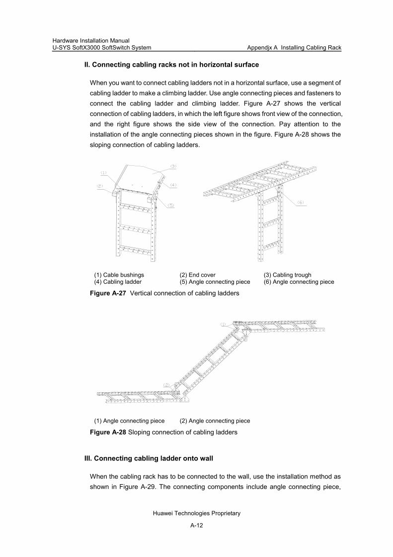
Hardware Installation Manual U-SYS SoftX3000 SoftSwitch System Appendjx A Installing Cabling Rack
Huawei Technologies Proprietary
A-12
II. Connecting cabling racks not in horizontal surface
When you want to connect cabling ladders not in a horizontal surface, use a segment of cabling ladder to make a climbing ladder. Use angle connecting pieces and fasteners to connect the cabling ladder and climbing ladder. Figure A-27 shows the vertical connection of cabling ladders, in which the left figure shows front view of the connection, and the right figure shows the side view of the connection. Pay attention to the installation of the angle connecting pieces shown in the figure. Figure A-28 shows the sloping connection of cabling ladders.
(1) Cable bushings (2) End cover (3) Cabling trough (4) Cabling ladder (5) Angle connecting piece (6) Angle connecting piece
Figure A-27 Vertical connection of cabling ladders
(1) Angle connecting piece (2) Angle connecting piece
Figure A-28 Sloping connection of cabling ladders
III. Connecting cabling ladder onto wall
When the cabling rack has to be connected to the wall, use the installation method as shown in Figure A-29. The connecting components include angle connecting piece,

Hardware Installation Manual U-SYS SoftX3000 SoftSwitch System Appendjx A Installing Cabling Rack
Huawei Technologies Proprietary
A-13
insulating plate, insulating washer, fastener and expansion bolt. Insulating plate and insulating washer are used to ensure insulation between the cabling rack and the wall. Meanwhile, big flat washer (φ8 of GB96-85) is used to replace the washer for the expansion bolt to increase the contact area between the washer and the insulating washer
(1) Insulating washer (2) Insulating plate (3) Big flat washer (4) Spring washer (5) Nut (6) Channel-section steel (7) Angle connecting piece (8) Expansion bolt
Figure A-29 Connecting the cabling rack into the wall
A.3.5 Installing Cabling Rack in Suspension Mounting Mode or Ground Supporting Mode
You can use suspension mounting mode or ground supporting mode when cabling rack is not placed against the wall. The suspension mounting mode is similar to the ground supporting mode, except that in the former installation mode, the cabling rack is connected to the ceiling, while in the latter the cabling rack is connected to the ground. The connecting components include channel-section steels, angle connecting pieces, fasteners and expansion bolts. To install a cabling rack in suspension mounting mode or ground supporting mode, use two pieces of channel-section steels to connect the cabling ladder to the ceiling or the ground. The installation method is the same as that of connecting cabling rack to the wall.
Each piece of channel-section steel is 2.5 m long. You can cut proper length according to the heights of the cabling rack and of the equipment room. If the required length is

Hardware Installation Manual U-SYS SoftX3000 SoftSwitch System Appendjx A Installing Cabling Rack
Huawei Technologies Proprietary
A-14
longer than 2.5 m, connect two pieces of channel-section steel by channel-section connecting piece with the same method as connecting cabling ladders. Meanwhile, paint the cut cross sections.
Because the spacing between the holes in the channel-section steel is 50 mm, the spacing between the suspenders or between the supporting levers must be an integral multiple of 50 mm. Otherwise, it is impossible to proceed with the installation. It is recommended that each segment of the cabling ladder is hung or supported by two sets of suspenders or supporting levers, and the spacing between two suspenders or between two supporting levers is 1250 mm .
When the suspension mounting mode or ground supporting mode is adopted, the suspenders or the supporting levers have to be installed at the outer side of the cabling ladder to facilitate the placement of cabling trough. Meanwhile, insulating plate and insulating washer must be used to ensure the insulation between the suspension components and the ceiling, or between the ground supporting components and the ground, as shown in Figure A-30.
(1) Angle connecting piece (2) Channel-section steel (3) Washer 8 (GB96-85) (4) Insulating washer (5) Insulating plate (6) Expansion bolt
Figure A-30 Suspension mounting mode or ground supporting mode

Hardware Installation Manual U-SYS SoftX3000 SoftSwitch System Appendjx A Installing Cabling Rack
Huawei Technologies Proprietary
A-15
A.3.6 Installing Triangular Support
Note:
The spacing between two triangular supports must be an integral multiple of 50 mm; otherwise, cabling ladders cannot be connected and fixed to triangular supports. A spacing of 1250 mm is recommended between two triangular supports, that is, each segment of cable ladder is supported by two triangular supports.
When cabling rack is placed against the wall, a triangular support is used to support the cabling rack. The triangular support adopts a welded structure, and it is fixed onto the wall by expansion bolts. It provides holes in its horizontal beam for installing cabling ladder. The triangular support has three specifications corresponding to the 200mm-wide, 400mm-wide, and 600mm-wide cabling ladders respectively. A larger triangular support can be used to support smaller cabling ladder, but it is not recommended here. The sizes of their installation holes in the wall are the same.
To install a triangular support, use expansion bolts to fix the support onto the wall. Use big flat washers (φ8 of GB96-85) to replace the flat washers of the expansion bolts. Meanwhile, install two insulating plates between the vertical beam of the triangular support and the wall, and install an insulating washer between the nut and the vertical beam.
To install cabling ladder onto the triangular support, place it directly on the horizontal beam of the triangular support. Align the holes on the lower side of the channel-section steel with the holes in the horizontal beam of the triangular support, and then fix them with fasteners, as shown in Figure A-31.

Hardware Installation Manual U-SYS SoftX3000 SoftSwitch System Appendjx A Installing Cabling Rack
Huawei Technologies Proprietary
A-16
(1) Cabling ladder (2) Insulating plate (3) Expansion bolt (4) Vertical beam of triangular support (5) Triangular support (6) Horizontal beam of triangular support
Figure A-31 Installation of triangular support
A.3.7 Installing Cabling Rack over Cabinet
I. Introduction to installation ways
Cabling rack can be installed over the cabinet in the following two ways (Generally, cable distribution trough is not configured on the top of cabinet for the purpose of improving system heat dissipation).
If shockproof support is installed on the cabinet, connect the cabling rack with the quake-proof support.
If no shockproof support is installed on the cabinet, connect the cabling rack with the cabinet by climbing ladder.
II. Connecting cabling rack with shockproof support
Shockproof support on the top of cabinet is welded with channel steel, and it can meet the strength requirements. It can be fixed to the two bolt holes on top of cabinet. There are bolt holes on the top plate of the shockproof support, used for fixing and bearing the cabling rack (cabling ladder). Figure A-32 and Figure A-33 show the connection method.

Hardware Installation Manual U-SYS SoftX3000 SoftSwitch System Appendjx A Installing Cabling Rack
Huawei Technologies Proprietary
A-17
(1) Cabinet (2) Shockproof support (3) Flat washer 8 (4) Spring washer (5) Blot M8x20
Figure A-32 Connection of cabinet and shockproof support
(1) Cabinet (2) Shockproof support (3) Cabling rack (4) Flange bolt M8x20 (5) Flange nut M8
Figure A-33 Connection of cabling rack and shockproof support

Hardware Installation Manual U-SYS SoftX3000 SoftSwitch System Appendjx A Installing Cabling Rack
Huawei Technologies Proprietary
A-18
III. Connecting cabling rack with climbing ladder
If there is no support installed on the top of cabinet, use climbing ladder based on the size of the connecting holes provided on the top of cabinet. For specific connecting method for climbing ladder, refer to the right figure in Figure A-27 or Figure A-28.
A.3.8 Installing Accessories
I. Installing cable-through clip
Cable-through clip can be divided into two types according to whether cabling rack has cabling trough or not. Figure A-34 illustrates the case when cabling trough is not configured on cabling rack, in which, upward cable-through clip is used. When cabling trough is configured on cabling rack, downward cable-through clip is used to ensure that the upper plane of cable-through clip stays on the same level with the uppermost plane of cabling rack, and to facilitate cabling. Generally, cable-through clip is installed on the cabling ladder on the top of cabinet, and the required quantity and location depend on actual conditions of the installation site.
(1) Cable-through clip (2) Upper hole of cable-through clip (3) Lower hole of cable-through clip
Figure A-34 Installation of cable-through clip when cabling trough is not configured on cabling rack
II. Installing baffle rings
Baffle rings are directly snapped at both sides of a cabling trough. Configuring baffle rings can increase the height of a cabling trough to prevent cables from going beyond the cabling trough. Each segment of cabling trough uses four such rings and they are distributed evenly at both sides, as shown in Figure A-23.

Hardware Installation Manual U-SYS SoftX3000 SoftSwitch System Appendjx A Installing Cabling Rack
Huawei Technologies Proprietary
A-19
III. Installing end covers
End covers are installed at the ends of a cabling ladder. Wherever possible, end covers must be installed to provide better appearance and prevents unintended damage to cables.
IV. Intalling cable bushings
Cable bushings are installed at the bottom edge of a cabling trough, used to prevent cables from any possible damage. Any uncovered bottom edge of cabling troughs must be installed with cable bushing. Left part in Figure A-27 shows the installation of end cover and cable bushing.

Hardware Installation Manual U-SYS SoftX3000 SoftSwitch System Appendix B Engineering Labels for Cables
Huawei Technologies Proprietary
B-1
Appendix B Engineering Labels for Cables
B.1 Introduction to the Appendix
This appendix contains the following sections:
Introduction to Labels Engineering Labels for External Cables of Alarm Box Engineering Labels for Ethernet Cables Engineering Labels for Optical Fibers Engineering Labels for Trunk Cables Engineering Labels for Subscriber Cables Engineering Labels for Power Cables
B.2 Introduction to Labels
B.2.1 Functions of Engineering Labels
Engineering labels are affixed to both ends of various cables to identify the physical positions of cables on different devices. Labels facilitate correct and orderly connection of cables, and easy maintenance after the installation.
Note:
If there is special requirement from the customer for the description method of the labels, the labels shall be printed accordingly. However, this must be stated in the self-check report.
B.2.2 Label Material Specifications
The label material is polyester (PET) with UL and CSA certifications. The material specifications are shown as follows:
Color Thickness Applicable ambient temperature Printing method
Chalk white 0.09 mm -29 °C – 149 °C Laser

Hardware Installation Manual U-SYS SoftX3000 SoftSwitch System Appendix B Engineering Labels for Cables
Huawei Technologies Proprietary
B-2
B.2.3 Type and Shape of Labels
I. Introduction to label types
There are two types of engineering labels, specialized for signal cables and power cables respectively. Power cables include AC power cables and DC power cables (excluding the power cable that connects the distribution cabinet and the cabinet). Signal cables include external cables of alarm box, Ethernet cables, optical fibers, trunk cables and subscriber cables (excluding the antenna feeders).
II. Labels for signal cables
The label for signal cables is L-shaped with fixed dimensions, as shown in Figure B-1 (expressed in mm).
(2)
10.0
84.0
1.5
0.6
2.0
1.0
(1)
11.0
11.0
7.5 7.05.5
5.5
5.5
5.57.0
7.537.0
TO:
(2)
(1)
(1) Dividing line (2) Cut dotted line
Figure B-1 Label for signal cables
The dividing lines on the label help to specify more clearly the position of a cable. For example, there is one between the cabinet number and the frame number and another one between the frame number and the slot number. The dividing line is 1.5 mm ×0.6 mm in size with the color of PONTONE 656c (light blue).
The cut dotted line helps to fold the label when affixing it to the cable, and its size is 1.0 mm ×2.0 mm.
There is a mark “TO:” (upside down in the figure) at the lower right corner of the label. The mark is used to identify the opposite end of the cable on which the label is affixed.

Hardware Installation Manual U-SYS SoftX3000 SoftSwitch System Appendix B Engineering Labels for Cables
Huawei Technologies Proprietary
B-3
III. Labels for power cables
The labels for power cables must be attached to the identification plate on the cable ties that are bundled to the cable. The identification plate has an embossment of 0.2 mm ×0.6 mm around (symmetric on both sides), and the area in the middle is for affixing the label, as shown in Figure B-2 (expressed in mm):
(1)
(2)
(3)
26.2
12.2
0.6
11
10
100
R1.0
25
1.5
0.6
TO:
(1) Cable tie (2) Label (3) Dividing line on the label
Figure B-2 Label for power cables
B.2.4 Printing Labels
I. Introduction to label printing
The contents can be printed or written on the labels. Printing is recommended for the sake of high efficiency and eye-pleasant layout.
II. Template for printing
The Word-format template is available for label printout. You can download the template from http://tech-support.huawei.com/asp/comm/index.asp (path: //support/technical document/project management/installation and maintenance/document/others), or get the template from Huawei local office.
When using the template, you can directly modify the contents on the template, and the following must be observed:
The settings of centered characters, direction, and fonts must not be changed. When there are too many characters to be filled in, zoom out the characters, but
make sure the printouts are clear and legible.

Hardware Installation Manual U-SYS SoftX3000 SoftSwitch System Appendix B Engineering Labels for Cables
Huawei Technologies Proprietary
B-4
III. Cells merging on the template
To merge the cells, you need first recover the table structure (if gridlines are displayed, you can start from Step 3 directly).
1) Select the menu item [Edit/Select All]. 2) Select the menu item [Format/Borders and Shading/Borders]. Select Box and
click <OK>. 3) Drag the mouse to select the cells to be merged and select the menu item
[Table/Merge Cells].
If two merged cells are still not enough to accommodate the characters, use multiple lines.
IV. Requirements for the printer
To print the labels, laser jet printer must be used, although there is no restriction on the model of the printer. Before printing the label, set up the page and try the printing on ordinary blank paper (both sides are blank):
1) Cover the blank paper onto the whole page of label paper, and check whether the page setup conforms to the requirement.
2) Make sure the printer properties, such as "paper size" and “direction”, have been set correctly.
3) If the warning prompt as shown in Figure B-3 appears before printing, click <Ignore> to continue the printing.
Figure B-3 Warning prompt before printing
If the printout confoms to the requiremnt, print it to label paper. If the printout does not conform, adjust the page setup and try the printing again, until the correct printout is produced. The method of adjusting the page setup is as follows:
1) Select the menu item [File/Page Setup]. 2) Select the Margins tab page. 3) Select Left for Gutter Position. 4) Set Header and Footer as 0, and adjust the values of Top, Bottom, Left, and
Right.
After the page setup has been made correct, save it for future use. This page setup is only necessary in the first time you use the template to print the labels.

Hardware Installation Manual U-SYS SoftX3000 SoftSwitch System Appendix B Engineering Labels for Cables
Huawei Technologies Proprietary
B-5
V. Requirements for feeding the printer
Different from the ordinary paper, the label paper is composed of two pages. No matter what model of printer you are using, feed in the labels one after another by hand. Never use the auto-feed mode in order to avoid jamming the labels. Different models of printers may have different feeding modes, make sure to feed in the labels correctly.
VI. Requirements for printed labels
Make sure the printed labels satisfy the following requirements:
All the printouts must be on the label, and nothing must be printed on the bottom page of the label.
Contents in the cells must be aligned in the center. In a single-line printout, the dividing lines and the mark “TO” must not be covered by the printed characters.
When the cells are merged and the printouts are made in multiple lines, avoid covering the mark “TO” when printing the texts by using the space bar to move the printing contents to the next line.
B.2.5 Writing Labels
Use the black oiliness markers delivered together with the device to write the labels.
In special cases, black ball-pens are allowed, although not recommended. When writing with the ball-pen, take care not to leave the oil on the label, which may contaminate the label and blur the words..
Note:
The delivered marker has two nibs. Make sure to use the smaller nib to write on the labels.
For the sake of easy recognition and good looking, the font in handwriting must be close to the standard typeface as much as possible. Table B-1 shows the standard typeface.

Hardware Installation Manual U-SYS SoftX3000 SoftSwitch System Appendix B Engineering Labels for Cables
Huawei Technologies Proprietary
B-6
Table B-1 Standard typeface for handwriting
0 1 2 3 4 5 6 7 8
9 A B C D E F G H
I J K L M N O P Q
R S T U V W X Y Z
Write the characters in proper size, and the direction is as shown in Figure B-4:
TO:
Figure B-4 Writing direction of the label
B.2.6 Affixing Labels
I. Affixing label to signal cable
After printing or writing the label, remove the label from the bottom page and affix it to the signal cable, or the identification plate of the power cable.
The steps to affix a label to a signal cable are shown in Figure B-5, Figure B-6 and Figure B-7. The finished labels must be on the right or top of the cables, according to different cabling methods. The left part of the figures shows the method to affix the label when the cable is laid vertically, while the right part of the figures shows the method to affix the label when the cable is laid horizontally.
The label is affixed 2 cm from the connector on the signal cable. In special cases, for example, to avoid cable bent or affecting other cables, other positions are allowed to affix the labels.
The steps to affix a label to a signal cable are as follows:
1) Stick the label to the proper position on the cable, fold the narrow part of the label according to the directions shown in Figure B-5.

Hardware Installation Manual U-SYS SoftX3000 SoftSwitch System Appendix B Engineering Labels for Cables
Huawei Technologies Proprietary
B-7
Stick side
Fold to right
Cable
Stick side
Fold down
Cable
Figure B-5 Sticking the label onto proper position of the signal cable
The lengh of the narrow part is based on an external cable diameter of 2.6mm, after this part has been stuck to the back of the label, it may not overlap the entire printed part.
2) Fold the printed part along the dotted line according to the directions shown in Figure B-6.
Cable
Stick side
Fold up
Cable
Stick side
Fold to right
Figure B-6 Folding up the label
3) After the printed part of the label has been folded up, the narrow part of the label must be covered completely, as shown in Figure B-7.

Hardware Installation Manual U-SYS SoftX3000 SoftSwitch System Appendix B Engineering Labels for Cables
Huawei Technologies Proprietary
B-8
TO:A03 33 33 33 33
Cable
TO:
A03 33 33 33 33
Cable
Figure B-7 Appearance of affixed labels on signal cables
II. Affixing label to power cable
Remove the label from the bottom page, then affix it to the identification plate on the cable tie. The label must be stuck to the rectangular flute, and must be stuck to only one side of the identification plate. Make sure to affix the labels on the same side of the identification plates. The cable ties are bundled at 2cm from the connectors, and other positions are allowed in special circumstances.
Cable ties must be bundled on both ends of a cable. After the bundling, the finished identification plate must be on top of the cable in horizontal cabling, or on the right side of the cable in vertical cabling. Make sure the label is facing out, as shown in Figure B-8.
Cable
TO:B03 -48V2
Cable
TO:
B03 -48V2
Figure B-8 Appearance of affixed labels on power cables

Hardware Installation Manual U-SYS SoftX3000 SoftSwitch System Appendix B Engineering Labels for Cables
Huawei Technologies Proprietary
B-9
B.2.7 Information Carried on Labels
I. Information for power cables
Labels for power cables are only affixed on one side of the identification plates. On the labels, there is information (the part after the mark “TO:”) about the location of the device on the other end of the cable, like the location of control cabinet, distribution cabinet or power socket.
II. Information for signal cables
The two sides of the label affixed on the signal cable carry information about the location of the ports connected to both ends of the cable, as shown in Figure B-9.
The information is given like this:
Area 1 contains the location information of local end of the cable. Area 2 (with the mark "TO:") contains the location information of the opposite end
of the cable. Area 3 has been folded up inside the label.
Area 3Area 1Area 2 TO:
Figure B-9 Printed parts on the label for signal cables
Seen from the cabling end of the equipment, the text part of the label is on the right side of the cable. The side with “TO:” that is facing outside carries the location information of the opposite end; and the other side carries the location information of the local end. Therefore, the information in Area 1 at one end is the same as the information in Area 2 at the other end of the cable, and vice versa. In other words, the local information at one end is called the opposite information at the other end.
B.2.8 Remarks
The following remarks are made for attentions.
When printing/writing and affixing labels, pay attention to keep the labels clean. Because the label paper is made of moistureproof and waterproof material,
ink-jet printers and ink pens are forbidden for printing and writing labels. Labels must be affixed with good order in alignment.

Hardware Installation Manual U-SYS SoftX3000 SoftSwitch System Appendix B Engineering Labels for Cables
Huawei Technologies Proprietary
B-10
Cable ties must be bundled in the same position of power cables, with identification plates on the same side.
The positions of “up”, “down”, “right” or “left” are all based on the viewpoint of the engineering person who is working on the label.
B.3 Engineering Labels for External Cables of Alarm Box
The external cables of alarm box are connected with the first subscriber cabinet of each row (used for power distribution). Labels pasted on the first cabinet of each row indicate which equipment is using the access terminal. Labels are not needed on the equipment side unless there is special requirement. In this case, only Area 2 of the label is filled in.
Table B-2 shows the information on the labels of alarm box external cables.
Table B-2 Information on labels affixed to the external cables of alarm box
Content Meaning Example
MN
MN: serial number of the cabinet in the equipment room
M: The cabinet rows from front to back are numbered from A to Z.
N: The cabinet columns from left to right are numbered from 01 to 99.
For example, A01 indicates a cabinet at Row A, Column 01.
Note:
Generally, the above numbering method is enough to identify the position of a specific cabinet. If cabinets are installed in a back-to-back manner, the facing direction of the cabinet must be specified, the numbering method like MNO is used. Here, “O” means the direction of the cabinet, which can be “A” or “B”. On the cable labels described below, this numbering method is used, unless otherwise stated.
The label on the alarm cable carries simple information, and only part of the text area needs to be filled in. It is recommended to keep the whole length of the label instead of cutting out the blank area.
Figure B-10 shows a label on the alarm cable, on which “A01” indicates that the alarm cable is connected from the first cabinet to the cabinet at Row A, Column 01 in the equipment room.
Hardware Installation Manual U-SYS SoftX3000 SoftSwitch System Appendix B Engineering Labels for Cables
Huawei Technologies Proprietary
B-11
Figure B-10 Example of the label on the alarm cable
B.4 Engineering Labels for Ethernet Cables
B.4.1 Introduction to the Labels
These labels are affixed to the Ethernet cables that connect the boards in the frames, or on the cables that connect HUBs and servers or agents of the value-added service (VAS) products.
B.4.2 Label Information Meanings
I. Introduction to information on labels
Table B-3 shows the information on both sides of the labels affixed to the Ethernet cables that connect the boards in the frames.
Table B-3 Information on labels affixed to the Ethernet cables
Content Meaning Example
MN: Cabinet number For example, A01
B: Frame number
Numbered in top-down order with two digits, for example, 01
C: Physical slot number
Numbered in top-down and left-right order with two digits, for example, 01
MN-B-C-D
D: Ethernet port number
Numbered in top-down and left-right order with two digits, for example, 01

Hardware Installation Manual U-SYS SoftX3000 SoftSwitch System Appendix B Engineering Labels for Cables
Huawei Technologies Proprietary
B-12
Content Meaning Example
MN: Cabinet number For example, B02
MN-Z Z: Location number
Valid location number of the terminal device onsite. If the cable is connected to a router in a cabinet, the serial numbers of the cabinet, the frame and the Ethernet interface of the router must be specified, for example, B02-03-12. If the cable is connected to the Network Management Station (NMS), specific location of the NMS must be given.
In VAS products, the information provided on the labels is different, subject to different devices that the Ethernet cables are connecting.
II. Labels for Ethernet cable that connects HUB and server
The information provided on the labels includes:
The label at the HUB end indicates the number of the frame and cabinet where the HUB locates, and the serial number on the HUB.
The label at the server end indicates the number of the frame and cabinet where the server locates. In case it is a stand-alone server, specific position of the server should be provided.
III. Labels for Ethernet cable that connects HUB and agent
The information provided on the labels includes:
The label at the agent end contains the serial number of the Ethernet port. The definitions of the cabinet number and frame number are the same as those described in Table B-3 above.
If it is a stand-alone HUB without any cabinet or frame, the label contains specific location information that identifies the HUB.
The label contains the serial number of the HUB, the network port number of the agent and the location of the stand-alone server according to actual connection.
B.4.3 Label Example
Figure B-11 shows the label on the Etherent cable:

Hardware Installation Manual U-SYS SoftX3000 SoftSwitch System Appendix B Engineering Labels for Cables
Huawei Technologies Proprietary
B-13
Figure B-11 Example of the label on the Ethernet cable
“A01-03-10-05” indicates that on the local end of the Ethernet cable is connected with Ethernet Port 05, Slot 10, Frame 03 of the cabinet at Row A, Column 01 in the equipment room.
“B02-03-12” indicates that the opposite end of the Ethernet cable is connected with Ethernet Port 12, Frame 03 of the cabinet at Row B, Column 02 in the equipment room.
B.5 Engineering Labels for Optical Fibers
B.5.1 Introduction to the Labels
These labels are affixed to the optical fibers that connect the optical interfaces on the boards in a frame, or on the device boxes. There are two types of labels for optical fibers: one is for the fiber that connects the optical interfaces on two devices, the other is for the fiber that connects the device and the optical distribution frame (ODF).
B.5.2 Labels for Fiber that Connects Two Devices
I. Label information meanings
Table B-4 shows the information on both sides of the labels affixed to the optical fiber that connects two devices.

Hardware Installation Manual U-SYS SoftX3000 SoftSwitch System Appendix B Engineering Labels for Cables
Huawei Technologies Proprietary
B-14
Table B-4 Information on labels affixed to the fiber between two devices
Content Meaning Example
MN: cabinet number For example, A01
B: frame number Numbered in top-down order with two digits, for example, 01
C: physical slot number Numbered in top-down and left-right order with two digits, for example, 01
D: optical interface number Numbered in top-down and left-right order with two digits, for example, 05
MN-B-C-D-R/T
R: optical receiving interface
T: optical transmitting interface
MN: cabinet number
B: frame number
C: physical slot number
D: optical interface number
The meanings are the same as above. When the local device and the opposite end device are not in the same equipment room, MN can be the name of the equipment room. MN-B-C-D-R/T
R: optical receiving interface
T: optical transmitting interface
II. Label example
Figure B-12 shows the label on the optical fiber between two devices:
Figure B-12 Example of the label on the optical fiber between two devices
“A01-01-05-05-R” indicates that the local end of the optical fiber is connected with Optical Receiving Interface 05 on Slot 5, Frame 01 in the cabinet at Row A, Column 01 in the equipment room.

Hardware Installation Manual U-SYS SoftX3000 SoftSwitch System Appendix B Engineering Labels for Cables
Huawei Technologies Proprietary
B-15
“G01-01-01-01-T” indicates that the opposite end of the optical fiber is connected with Optical Transmitting Interface 01 on Slot 01, Frame 01 in the cabinet at Row G, Column 01 in the equipment room
B.5.3 Labels for Fiber that Connects the Device and the ODF
I. Label information meanings
Table B-5 shows the information on both sides of the labels affixed to the optical fiber that connects the device and the ODF.
Table B-5 Information on labels affixed to the fiber between the device and the ODF
Content Meaning Example
MN: cabinet number For example, A01
B: frame number Numbered in bottom-up order with two digits, for example, 01
C: physical slot number Numbered in top-down and left-right order with two digits, for example, 01.
D: optical interface number
Numbered in top-down and left-right order with two digits, for example, 05
MN-B-C-D-R/T
R: optical receiving interface
T: optical transmitting interface
MN: row number and column number of ODF
Numbered in the same rule as that of the cabinets, for example, G01 indicates an ODF at Row G, Column 01
B: row number of the terminal device
C: column number of the terminal device
Range from 01 to 99, for example, 01-01
ODF-MN-B-C-R/T
R: optical receiving interface
T: optical transmitting interface
II. Label example
Figure B-13 shows the label on the optical fiber between the device and the ODF.

Hardware Installation Manual U-SYS SoftX3000 SoftSwitch System Appendix B Engineering Labels for Cables
Huawei Technologies Proprietary
B-16
Figure B-13 Example of the label on the optical fiber between the device and the ODF
“ODF-G01-01-01-R” indicates that the local end of the optical fiber is connected with the optical receiving terminal at Row 01, Column 01 of the ODF at Row G, Column 01 in the equipment room.
“A01-01-05-05-R” indicates that the opposite end of the optical fiber is connected with Optical Receiving Interface 5 on Slot 05, frame 01 in the cabinet at Row A, Column 01 in the equipment room.
B.6 Engineering Labels for Trunk Cables
B.6.1 Introduction to the Labels
There are two types of labels for trunk cables. One type is used for the trunk cable connecting two devices, such as the trunk board and built-in transmission unit, or two trunk boards. The other type is used for connecting the device and the digital distribution frame (DDF).
The trunk cables include 75Ω/120Ω E1 cables, 120Ω T1 cables, 34M, 45M, 140M, 155M cables and 120-to-75Ω trunk cables, as well as clock cables.
B.6.2 Labels for Trunk Cable that Connects Two Devices
I. Label information meanings
Table B-6 shows the information on both sides of the labels affixed to the trunk cable that connects two devices.

Hardware Installation Manual U-SYS SoftX3000 SoftSwitch System Appendix B Engineering Labels for Cables
Huawei Technologies Proprietary
B-17
Table B-6 Information on labels affixed to the trunk cable between two devices
Content Meaning Example
MN: cabinet number For example, A01
B: frame number Numbered in bottom-up order with two digits, for example, 01
C: physical slot number Numbered in top-down and left-right order with two digits, for example, 01
D: cable number Numbered in top-down and left-right order with two digits, for example, 12
MN-B-C-D-R/T
R: optical receiving interface
T: optical transmitting interface
MN-B-C-D-R/T Same as above Same as above
II. Label example
Figure B-14 shows the label on the trunk cable between two devices:
Figure B-14 Example of the label on the trunk cable between two devices
“G01-01-05-12-T” indicates that the local end of the trunk cable is connected with the transmitting terminal of Trunk Cable 12 on Slot 05, Frame 01 in the cabinet at Row G, Column 01 in the equipment room.
“D02-01-01-10-R” indicates that the opposite end of the trunk cable is connected with the receiving terminal of Trunk Cable 10 on Slot 01, Frame 01 in cabinet at Row D, Column 02 in the equipment room
B.6.3 Labels for Trunk Cable that Connects the Device and the DDF
I. Label information meanings
Table B-7 shows the information on both sides of the labels affixed to the trunk cable that connects the device and the DDF.

Hardware Installation Manual U-SYS SoftX3000 SoftSwitch System Appendix B Engineering Labels for Cables
Huawei Technologies Proprietary
B-18
Table B-7 Information on labels affixed to the trunk cable between the device and the DDF
Content Meaning Example
MN: cabinet number For example, A01
B: frame number Numbered in bottom-up order with two digits, for example, 01
C: physical slot number Numbered in top-down and left-right order with two digits, for example, 01
D: cable number Numbered in top-down and left-right order with two digits, for example, 05
MN-B-C-D-R/T
R: optical receiving interface
T: optical transmitting interface
MN: row number and column number of the DDF
Numbered in the same rule as that of the cabinets, for example, G01 indicates a DDF at Row G, Column 01.
B: row number of the terminal
C: column number of the terminal
Range from 01 to 99, foe example: 01-01.
DDF-MN-B-C-D/R/T
D: direction A or B
R: optical receiving interface
T: optical transmitting interface
There is such a mark in DDF:
A: indicating the DDF terminals are connected to the optical network equipment
B: indicating the DDF terminals are connected to the switching equipment
II. Label example
Figure B-15 shows the label on the trunk cable between the device and the DDF:

Hardware Installation Manual U-SYS SoftX3000 SoftSwitch System Appendix B Engineering Labels for Cables
Huawei Technologies Proprietary
B-19
Figure B-15 Example of the label on the trunk cable between the device and the DDF
“A01-03-01-01-R” indicates that local end of the trunk cable is connected with the receiving terminal of Trunk Cable 01 in Slot 01, Frame 03 of the cabinet at Row A, Column 01 in the equipment room.
“DDF-G01-01-01-AR” indicates that the opposite end of the trunk cable is connected with the receiving terminal of Direction A (connected to optical network equipment) at Row 01, Column 01 of the DDF at Row G and Column 01 in the equipment room.
B.7 Engineering Labels for Subscriber Cables
B.7.1 Introduction to the Labels
The labels are affixed to both ends of the subscriber cables to identify the position of the cables on the device side and the main distribution frame (MDF) side.
B.7.2 Label Information Meanings
Table B-8 shows the information on both sides of the labels affixed to the subscriber cables.
Table B-8 Information on labels affixed to the subscriber cables
Content Meaning Example
MN: cabinet number For example, A01
B: frame number Numbered in bottom-up order with two digits, for example, 03
C: physical slot number Numbered in top-bottom and left-right order in two digits, for example, 01
MN-B-C-D
D: cable number Numbered in top-bottom and left-right order with two digits, for example, 01
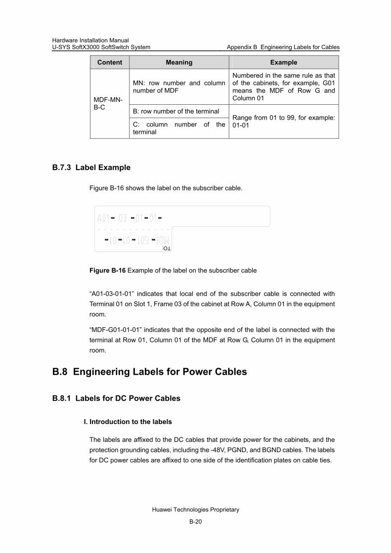
Hardware Installation Manual U-SYS SoftX3000 SoftSwitch System Appendix B Engineering Labels for Cables
Huawei Technologies Proprietary
B-20
Content Meaning Example
MN: row number and column number of MDF
Numbered in the same rule as that of the cabinets, for example, G01 means the MDF of Row G and Column 01
B: row number of the terminal
MDF-MN-B-C
C: column number of the terminal
Range from 01 to 99, for example: 01-01
B.7.3 Label Example
Figure B-16 shows the label on the subscriber cable.
TO:
Figure B-16 Example of the label on the subscriber cable
“A01-03-01-01” indicates that local end of the subscriber cable is connected with Terminal 01 on Slot 1, Frame 03 of the cabinet at Row A, Column 01 in the equipment room.
“MDF-G01-01-01” indicates that the opposite end of the label is connected with the terminal at Row 01, Column 01 of the MDF at Row G, Column 01 in the equipment room.
B.8 Engineering Labels for Power Cables
B.8.1 Labels for DC Power Cables
I. Introduction to the labels
The labels are affixed to the DC cables that provide power for the cabinets, and the protection grounding cables, including the -48V, PGND, and BGND cables. The labels for DC power cables are affixed to one side of the identification plates on cable ties.

Hardware Installation Manual U-SYS SoftX3000 SoftSwitch System Appendix B Engineering Labels for Cables
Huawei Technologies Proprietary
B-21
II. Label information meanings
Table B-9 shows the information carried on the labels for the DC power cables:
Table B-9 Information on labels affixed to the DC power cables
Content Meaning
MN(BC)--48V1
MN(BC)--48V2
MN(BC)-BGND
MN(BC)-PGND
MN(BC): BC is written right under MN.
On the equipment cabinet side, only MN is used to identify the cabinet.
On the power cabinet side, MN identifies the row and column number of the power distribution equipment like the control cabinet and distribution cabinet, BC identifies the row and column number of the -48V connecter (if there is no row number or column number, or the connecter can be identified without them, BC can be omitted). BGND and PGND have no row and column number for identification.
The label only carries location information about the opposite equipment, the control cabinet or the distribution cabinet, while information of the local end is not necessary. Table B-9 lists the information of two -48V power supplies on the label. The information for other DC voltages (such as 24V, 60V) should be given in similar methods.
III. Label example
Make sure that labels are affixed in correction direction. That is, after the cable ties are bundled onto the cable, the identification plates with the labels should face up, and the text on the labels in the same cabinet should be in the same direction, as shown in Figure B-17.
(1) (2)
TO: A01 -48V2 B08
TO: B03 -48V2
Figure B-17 Example of the labels on the DC power cable
In Figure B-17, (1) indicates the label on the equipment cabinet side, which carries the information about the position of the cable on the power distribution cabinet. (2)

Hardware Installation Manual U-SYS SoftX3000 SoftSwitch System Appendix B Engineering Labels for Cables
Huawei Technologies Proprietary
B-22
indicates the label on the distribution cabinet side, which carries the information about the position of the cable on the equipment cabinet side.
On the equipment cabinet side, the label marked “A01/B08--48V2” on the cable indicates that the cable is -48V2 DC supply, which is from the 8th connecter on the second row of -48V bus bar in the cabinet at Row A, and Column 1 in the equipment room.
On the distribution cabinet side, the label marked “B03--48V2” indicates that the cable is -48V2 DC supply, which is from the equipment cabinet at Row B, Column 03 in the equipment room.
Note:
In the power distribution cabinet (or the first power cabinet of a row in the transmission equipment room), every terminal on the -48V terminal block has a numeric identification, like “08” in “A01/B08--48V2” in the above example.
PGND and BGND are copper bars, on which all the terminals are connected. In this case, it is only necessary to specify the row and column of the power distribution cabinet. For example, “A01-BGND” means that the power cable is a BGND cable that connects to the BGND copper bar of the power distribution cabinet at Row A, Column 01 in the equipment room.
B.8.2 Labels for AC Power Cables
I. Introduction to the labels
The labels are affixed to the AC cables that provide power for the cabinets, and the protection grounding cables, including the POWER, PGND, and BGND cables. The 220V AC cables and related PGND and BGND cables are covered with insulating sheath, so the labels only need to contain the words of “AC" and the cabinet number. The labels for AC power cables are affixed to one side of the identification plates on cable ties.
II. Label information meanings
Table B-10 shows the information carried on the labels for the AC power cables.

Hardware Installation Manual U-SYS SoftX3000 SoftSwitch System Appendix B Engineering Labels for Cables
Huawei Technologies Proprietary
B-23
Table B-10 Information on labels affixed to the AC power cables
Content Meaning
MN-AC
MN: serial number of the cabinet or the socket where the power is led in
The location of the socket is marked out according to onsite situation. If the sockets can be identified by row number and column number, they can be numbered following the same rule for the cabinets. If the sockets cannot be identified by rows and columns, specify the detailed locations to avoid confusing with other sockets.
The label only carries location information about the opposite equipment and the power socket, while information of the local end is not necessary.
III. Label example
Make sure that labels are affixed in correction direction. That is, after the cable ties are bundled onto the cable, the identification plates with the labels should face up, and the text on the labels in the same cabinet should be in the same direction, as shown in Figure B-18:
TO: A01 AC
TO: B01 AC
(1) (2)
Figure B-18 Example of the labels on the AC power cable
In Figure B-18, (1) indicates the label on the equipment cabinet side, which carries the information about the position of the cable on the power socket. (2) indicates the label on the power socket side, which carries the information about the position of the cable on the equipment cabinet side.
On the equipment cabinet side, the label marked “A01-AC” indicates that the power cable is connected to the socket of Row A Column 01 in the equipment room.
On the power socket side, the label marked “B01-AC” indicates that the power cable is connected to the equipment cabinet at Row B, Column 01 in the equipment room.

Hardware Installation Manual U-SYS SoftX3000 SoftSwitch System Appendix C Assembling Cable Connectors
Huawei Technologies Proprietary
C-1
Appendix C Assembling Cable Connectors
C.1 Introduction to the Appendix This appendix contains the following sections:
C.2 Assembling Power Cable Connector
C.2.1 Introduction to Assembly Procedure
Note:
The method applies to the assembly of bare pressure terminals and 50–240 mm2 power cables.
Figure C-1 shows the procedure for assembling bare pressure terminals and a single cable.
Cut cable
Mount heat-shrinkable tube
Strip cable
Crimp cable
Shrink heat-shrinkable tube
Check cable
Stick label
End
Start
Figure C-1 Assembling bare pressure terminal and a single cable

Hardware Installation Manual U-SYS SoftX3000 SoftSwitch System Appendix C Assembling Cable Connectors
Huawei Technologies Proprietary
C-2
C.2.2 Assembling Power Cable Connector
I. Cutting cable
To cut the cable, do as follows:
1) Place and roll the cable coils on the support, as shown in Figure C-2. 2) Measure and cut off a segment of the cable according to the cable layout of the
project design.
(1)
(1)
(1) Rolling direction
Figure C-2 Cutting a cable
II. Mounting heat-shrinkable tube
To mount heat-shrinkable tube, do as follows:
1) Cut off the power cable with an arm saw.
Because the power cable comprises many core wires, and the wire pairs are fairly fine and soft, a denticulate arm saw (with the denticulate diameter of 0.8 mm) is recommended. If available, use wire clippers (model KT35) to cut the power cable.
2) Mount the heat-shrinkable tube onto the cable from the end stripped.
III. Stripping cable
Generally, special stripping tool or electrical knife is recommended. The AM35 wire stripper is recommended for round cables.
To strip the cable, do as follows:
1) Measure the cable length to be stripped.

Hardware Installation Manual U-SYS SoftX3000 SoftSwitch System Appendix C Assembling Cable Connectors
Huawei Technologies Proprietary
C-3
The stripped cable length depends on the length of the crimping sleeve behind the bare pressure terminal. For the JG bare pressure terminal commonly used by Huawei, the length of stripped cable is calculated using the formula:
L1=L2 + (2~3 mm)
where L1 is the stripped cable length and L2 the length of the effective crimping area of the JG terminal, as shown in Figure C-3.
2) Remove the multi-strand core wires at the insulation layer of the terminal end, and strand them tightly. The stranding direction should be the same as the original merging direction of the core wires.
(1)
(1) Crimping sleeve
Figure C-3 Stripping cable
Note:
When stripping cable, check with care whether the cable core wires have been seriously oxidized or corroded. If so, cut off the oxidized or corroded segment.
IV. Crimping cable
To crimp the cable, do as follows:
1) Crimp the cable with special crimping pliers or special molds. 2) Try to insert the core wires into the wire inlets of the terminal crimping sleeve until
they cannot be pushed further. Thus the core wires should protrude 2–3 mm from the terminal, as shown in Figure C-4.
3) Before crimping the wiring terminal, place the cable in the connection position so that the contact surface of the wiring terminal is parallel to the power bus. If they are not parallel, hold the end of the terminal with pliers to adjust it.
4) During crimping, use the mold with right cross section. The molding dies corresponding to the 4 types of power cables are shown in Figure C-5.
5) Ensure correct crimping position, as shown in Figure C-6.

Hardware Installation Manual U-SYS SoftX3000 SoftSwitch System Appendix C Assembling Cable Connectors
Huawei Technologies Proprietary
C-4
(2)
(1)
(1) Bare pressure terminal (2) Heat-shrinkable tube
Figure C-4 Connecting core wire with terminal crimping sleeve
(1) (2)
50mm 95mm 120mm 240mm2 2 2 2
(1) Bearing device (2) Compressing device
Figure C-5 Molding dies related to power cables
2 0 0
1 5 0 - 3 2 5
Figure C-6 Crimping cable

Hardware Installation Manual U-SYS SoftX3000 SoftSwitch System Appendix C Assembling Cable Connectors
Huawei Technologies Proprietary
C-5
V. Shrinking heat-shrinkable tube
As stipulated in the cable design drawings, mount the heat-shrinkable tube onto the position where the terminal and the cable are joined, and blow the tube with a heat gun until the tube shrinks and wraps up tightly, as shown in Figure C-7.
(1) Shrank heat-shrinkable tube
Figure C-7 Shrinking heat-shrinkable tube
Note:
The heat-shrinkable tube on the cable should wrap up the whole crimping sleeve of the bare pressure terminal, including the joint between the terminal and the cable.
VI. Checking cable
Table C-1 shows the normal tensile strength of the ready-made cables.
Table C-1 Tensile strength standard of ready-made cables
Cable Tensile strength
50 mm2 1 KN
95 mm2 2 KN
120 mm2 2.5 KN
240 mm2 5 KN
The cable with an oxidized terminal surface and damaged cable sheath is substandard.
VII. Labeling
Attach labels (provided with the goods) to both ends of the power cable. For details, refer to Appendix B "Engineering Labels for Cables".

Hardware Installation Manual U-SYS SoftX3000 SoftSwitch System Appendix C Assembling Cable Connectors
Huawei Technologies Proprietary
C-6
C.2.3 Application of Crimping Tool
I. Introduction to crimping tool
The crimping tools of different types are used for different purposes. The application of the crimping tool SS-325 (usually used by Huawei) for large-section power cable terminals is illustrated in Figure C-8.
(1) Fixing handle (2) Hydraulic head (3) Hand level (4) Fixing rod (5) Hydraulic switch
Figure C-8 SS325 parts
II. Using crimping tool
Note:
Improper installation of the fixed handle, the pressing and stressed components will reduce the life cycle of the crimping tool.
The steps for using crimping tool are as follows:
1) Select the crimping component as required. 2) Assemble the compressing device, bearing device and fixing handle for the
crimping tool. 3) Release the fixing handle and place the tool in right place. 4) Turn on the hydraulic switch to put the compressing device into the in-service state,
and lift the hand level. 5) Place the cable to be crimped. 6) Push down the hand level to crimp the cable. 7) Check that the cable is well crimped.
After the crimping, a black line will appear at the hydraulic switch indicating that the crimping is finished normally (as for the tool of type SS0325, there is no such a line).

Hardware Installation Manual U-SYS SoftX3000 SoftSwitch System Appendix C Assembling Cable Connectors
Huawei Technologies Proprietary
C-7
Caution:
If the black line does not appear after the crimping, stop using the tool and have it repaired.
8) Turn off the hydraulic switch.
Turn off the hydraulic switch after the operation and take out the crimping components.
III. Maintenance and storage
It is required to regularly oil the crimping components, hydraulic switch and the tool body.
After using the tool, place it in a cool and ventilated place unreachable for children. Meanwhile, avoid direct sunshine.
IV. Filling and replacing oil
The oil in the tool should be replaced completely every two years, and the oil can be purchased in related authorized shop.
Caution:
Wear gloves when filling oil. Eye contact or skin contact of the oil may cause inflammation.
The oil is inedible. Put it in the place unreachable for children. In the case of eye contact, wash eyes with clean water within 15 minutes and seek
medical assistance as soon as possible. In the case of skin contact, wash the area thoroughly with clean water. Dispose it according to the requirements of the related law for environmental
protection.
The steps for filling and replace oil are as follows:
1) Turn off the hydraulic switch. 2) Screw off the fixing rod to expose the oil-embolus. 3) Put the oil-embolus upward, and screw off the oil plug. 4) Fill in oil with a little oil can. 5) After a while, tap the tool against something hard to expel the air inside it, and then
fill oil again. Repeat above steps till the pot is full.

Hardware Installation Manual U-SYS SoftX3000 SoftSwitch System Appendix C Assembling Cable Connectors
Huawei Technologies Proprietary
C-8
C.3 Assembling RJ45 Connector
C.3.1 Introduction to Assembly Procedure
Note:
The method applies to the assembly of RJ45 connector with straight through network cable and crossover network cable.
Figure C-9 shows the procedure for assembling an RJ45 connector.
Strip cable
Weld pin
Crimp outerconnector
Check cable
Stick label
End
Start
Figure C-9 Flowchart of assembling RJ45 connector
C.3.2 Assembling RJ45 Connector
I. Stripping and cutting cable
The length of the stripped segment on either cable is "L + (2–3 mm)", as shown in Figure C-10. The meaning of "L" is shown in Figure C-12, while "2–3 mm" represents the length reserved for wire cutting and sorting.
Figure C-10 Length of stripped cable segment

Hardware Installation Manual U-SYS SoftX3000 SoftSwitch System Appendix C Assembling Cable Connectors
Huawei Technologies Proprietary
C-9
Caution:
When stripping the cable, make sure that the end of the sheath is neatly stripped and the cutting angle is vertical to the cable.
For the shielded cable, avoid damaging the shield layer when stripping the protection layer. After the protection layer is stripped, fold the shielding layer backwards to the root of the cable sheath, as shown in Figure C-11.
The core wires, especially for the round communication cables, should be cut neatly. Before cutting, spread the core wires evenly apart and cut them neatly with the cutting tool, as shown in Figure C-12.
The structure and dimensions of the truncated cable should be in accordance with the requirements shown in Figure C-12. That is, the core wire should be equal to "L" in length.
(1) Folded shielding layer
Figure C-11 Folded shielded cable
Figure C-12 Bare wires of a cable
II. Inserting cable
The requirements are as follows:
The 8-core flat telephone line should be inserted from the tail of the RJ45 connector, till the point A of the connector engages the casing of power cable.
Each core wire should be inserted along the cable trough to the head of the connector, and all the core wires should be flush with the head of the connector, as shown in Figure C-13.

Hardware Installation Manual U-SYS SoftX3000 SoftSwitch System Appendix C Assembling Cable Connectors
Huawei Technologies Proprietary
C-10
1) The round communication cable should be inserted into the connector in the same way as 8-core flat telephone line. The core wire end should be flush so that it is easy to be put in position.
2) The shielded cable can be inserted in the shielded RJ45 connector in the same way described above, with the folded shielding layer attaching the built-in shielding piece at the tail of the RJ45 connector and butting against point A of the connector. See Figure C-13.
(7)
(6)
(8)
(5)(4)
(3)
(2)
(1)
(1) Shielding piece (2) External shielding piece (3) Cable insertion direction(4) Built-in shielding piece (5) Point A (6) Locking piece (7) Core wires flushing with cable end (8) Metal cutter
Figure C-13 RJ45 connector
Note:
The cable should be inserted in the order specified in the cable design drawings. Figure C-14 and Figure C-15 illustrate the wires of crossover cable and straight through cable.
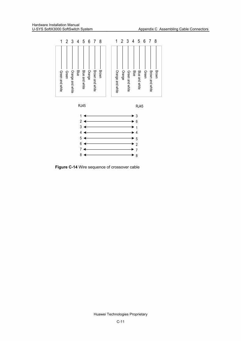
Hardware Installation Manual U-SYS SoftX3000 SoftSwitch System Appendix C Assembling Cable Connectors
Huawei Technologies Proprietary
C-11
RJ45 RJ45
1234567
3614527
Green and whiteGreenOrange and whiteBlueBlue and whiteOrangeBrown and whiteBrown
1 2 3 4 5 6 7 8 1 2 3 4 5 6 7 8
8 8
Orange and whiteOrangeGreen and whiteBlueBlue and white
GreenBrown and whiteBrown
Figure C-14 Wire sequence of crossover cable
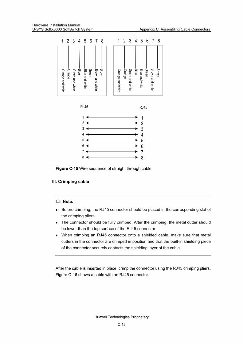
Hardware Installation Manual U-SYS SoftX3000 SoftSwitch System Appendix C Assembling Cable Connectors
Huawei Technologies Proprietary
C-12
1 2 3 4 5 6 7 8 1 2 3 4 5 6 7 8
RJ45 RJ45
12345678
12345678
Orange and whiteOrangeGreen and whiteBlueBlue and whiteGreenBrown and whiteBrown
Orange and whiteOrangeGreen and whiteBlueBlue and whiteGreenBrown and whiteBrown
Figure C-15 Wire sequence of straight through cable
III. Crimping cable
Note:
Before crimping, the RJ45 connector should be placed in the corresponding slot of the crimping pliers.
The connector should be fully crimped. After the crimping, the metal cutter should be lower than the top surface of the RJ45 connector.
When crimping an RJ45 connector onto a shielded cable, make sure that metal cutters in the connector are crimped in position and that the built-in shielding piece of the connector securely contacts the shielding layer of the cable.
After the cable is inserted in place, crimp the connector using the RJ45 crimping pliers. Figure C-16 shows a cable with an RJ45 connector.

Hardware Installation Manual U-SYS SoftX3000 SoftSwitch System Appendix C Assembling Cable Connectors
Huawei Technologies Proprietary
C-13
Figure C-16 A ready-made RJ45 connector
IV. Inspecting cable
The inspection items include:
Inspect the appearances of all the connectors carefully. The connectors with shell breakage or evident crack, locking piece breakage or crack, or improper cable insertion should be discarded.
Inspect all the cables carefully. The sequence of the wires should be in line with the design requirements.
Carry out continuity check on all cables. The continuity ratio should be 100%. No short circuit should be found between cables.
Note:
For the shielded cable assembled with shielded RJ45 connector, continuity check should be performed between the shielding shell of the connector and the shielding layer of the cable.
V. Labeling
Attach the ready-made labels to both ends of the cable. For details, refer to Appendix B "Engineering Labels for Cables".
C.4 Assembling SMB Connector
C.4.1 Introduction to Assembly Procedure
Note:
The method applies to the assembly of SMB connector with external clock cable and trunk cable.
Figure C-17 shows the procedure for assembling SMB connector.

Hardware Installation Manual U-SYS SoftX3000 SoftSwitch System Appendix C Assembling Cable Connectors
Huawei Technologies Proprietary
C-14
Mount heat-shrinkable tube
and crimp sleeve
Strip cable
Weld pin
Crimp outerconductor
Shrink heat-shrinkable tube
Inspect cable
End
Start
Figure C-17 Procedure for assembling SMB connector
C.4.2 Assembling SMB Connector
I. Mounting heat-shrinkable tube and crimping sleeve
Figure C-18 illustrates how to mount the heat-shrinkable tube and crimp it.
(1) (2)
(1) Heat-shrinkable tube (2) Crimping sleeve
Figure C-18 Mounting heat-shrinkable tube and crimping sleeve
II. Stripping cable
Strip off the shielding layer and the inner insulation layer of the cable with a wire stripper. The shielding layer and the inner insulation layer should not be damaged. The cable sheath and the end surface of the inner insulation layer should be cut neatly and smoothly. The specification of the stripped length is shown in Figure C-19 (Unit: mm).

Hardware Installation Manual U-SYS SoftX3000 SoftSwitch System Appendix C Assembling Cable Connectors
Huawei Technologies Proprietary
C-15
(3)
(4 )11
2 .3
(1)
4 .5
(2 )
(1) Sheath (2) Inner insulation layer (3) Inner conductor (4) Shielding layer
Figure C-19 Stripping cable
III. Welding pin
Caution:
During the welding, the inner insulation layer should not be scalded. Try not to let the soldering tin flow out to the exterior face of the pin while welding. In
the case of outflow, the tin must be cleaned up lest it should affect the next step.
Use the solder to weld the pin with the inner conductor of the cable together. The temperature of the melting point should be above 125°C.
When welding, insert the inner conductor of the cable into the central hole at the rear of the pin until the boss at the pin end contacts the inner conductor of the cable, as shown in Figure C-20.
(1) Inner insulation layer (2) Boss
Figure C-20 Welding pin

Hardware Installation Manual U-SYS SoftX3000 SoftSwitch System Appendix C Assembling Cable Connectors
Huawei Technologies Proprietary
C-16
IV. Crimping outer conductor
Caution:
Before crimping, the SMB connector to be crimped should be checked. If the shielded cables lay nakedly outside the crimping tube, the cable should be trimmed with scissors.
When crimping, the SMB connector should be placed in the right place to match with the molding-die of the crimping pliers.
The steps for crimping outer conductor are as follows:
1) Place the knurled cylinder of the SMB connector between the inner insulation layer and the shielding layer of the cable.
2) Make the shielding layer attach evenly to the knurled cylinder. 3) Have the needle lug butted against the inner insulation core of the connector. See
Figure C-21.
(4 )
(2 )
(1 )
(3 )
(1) Shielding layer covering the knurled cylinder evenly (2) Inner insulation core of the connector (3) Pin (4) Coaxial connector
Figure C-21 Crimping an SMB connector onto a coaxial cable
4) Push the crimping tube to cover the shielded cable entirely. 5) Crimp with the SMB crimping pliers.
V. Shrinking heat-shrinkable tube
Put the heat-shrinkable tube at the joint of the terminal and the cable, and blow the tube using a heat gun until the tube shrinks and wraps up tightly. See Figure C-22.

Hardware Installation Manual U-SYS SoftX3000 SoftSwitch System Appendix C Assembling Cable Connectors
Huawei Technologies Proprietary
C-17
(1 )
(1) Shrinking
Figure C-22 Shrinking heat-shrinkable tube
VI. Inspecting cable
The inspection items include:
Use a multimeter to check the continuity between the connector pin and the inner conductor of the coaxial cable and that between the outer shell of the connector and the shielding layer of the coaxial cable.
Use a multimeter to check that the inner and the outer conductor are not short-circuited.
Apply proper force (about 60 N) to pull the inner contact pin outward, there should be no obvious displacement for the inner contact pin.
Check that there is no shielded cable laying naked outside or no contact pins out of position.

Hardware Installation Manual U-SYS SoftX3000 SoftSwitch System
Appendix D Requirements for Equipment Operating Environment
Huawei Technologies Proprietary
D-1
Appendix D Requirements for Equipment Operating Environment
D.1 Observed Standards
This document is based on the standards of the People’s Republic of China. If the on-site situation is inconsistent with the document, refer to the local standards and regulations
D.2 Requirements for Equipment Room
D.2.1 Site Requirements
The communication equipment should run in a favorable environment. Its equipment room should be located at a place free from high temperature, dust, toxic gases, explosive materials or instable voltage, and away from great vibrations, strong noise or power transformer stations. During project designing, such factors as hydrographic, geological, seismic, power supply and transportation factors should be taken into consideration to select the site in line with the engineering and environmental requirements for the communication equipment.
The construction, structure, heating and ventilation, power supply, lighting, and firefighting designs of the communications equipment room are done by specialized construction designers and the environment design requirements of the switch should be strictly followed. The communication equipment room shall be designed in accordance with the industrial, environmental protection, fire-fighting and civil defense requirements, as well as the current standards/regulations of the local country or region and the requirements of special technical process for building construction design.
Site requirements are as follows:
The site should be kept away from pollution sources. For sources of heavy pollution such as the smeltery and coal mine, keep a distance of 5 km. For sources of medium pollution such as the chemical, rubber and galvanization industries, keep a distance of 3.7 km. For sources of light pollution such as food and tanner industries, keep a distance of 2 km. If these sources of pollution cannot be avoided, the equipment room must be in the perennial upwind

Hardware Installation Manual U-SYS SoftX3000 SoftSwitch System
Appendix D Requirements for Equipment Operating Environment
Huawei Technologies Proprietary
D-2
direction of the pollution sources. In addition, quality equipment room or protection product must be adopted.
The ventilation port for air exchange of the equipment room must be kept away from the exhaust of city waste pipes, big cesspools and sewage treatment tanks. The equipment room should be kept in the positive pressure state lest the corrosive gases enter the equipment room and erode components and circuit boards.
The equipment room should be kept away from the industrial and heating boilers. It is best to locate the equipment room in or above the second floor. If this
requirement cannot be satisfied, the ground for equipment installation in the equipment room shall be at least 600 mm above the maximum flood level in the local record.
The equipment room should be kept away from livestock farms. If this requirement cannot be satisfied, it should be located in the perennial upwind direction of the livestock farms.
The equipment room should be kept 3.7 km away from the seaside or salt lake. If this requirement cannot be satisfied, the equipment room should be airtight with cooling facilities. In addition, the alkalized soil cannot be used as the construction material. Otherwise, the equipment applicable in atrocious environment must be adopted.
The old livestock room or the chemical fertilizer warehouse cannot be used as the equipment room.
The equipment room should be solid enough to withstand wind and downpour. The equipment room should be kept away from the road or sand field with dusts
flying around. If this requirement cannot be satisfied, the windows and doors of the equipment room should be kept away from the sources of pollution
D.2.2 Equipment Room Composition
The equipment room is used to install switching equipment, communication transmission devices, power supply devices, and other auxiliary devices. To facilitate maintenance and management, it is required to install them in different room. Figure D-1 shows the layout of equipment room.

Hardware Installation Manual U-SYS SoftX3000 SoftSwitch System
Appendix D Requirements for Equipment Operating Environment
Huawei Technologies Proprietary
D-3
Battery room
Control room
Switching roomTransmissionroom
Power distributionroom
Powertransformation
room
Diesel generator
Communication cableand optical fiber
Power cable
Figure D-1 Equipment room layout
The overall layout principles are as follows:
The equipment room layout meets the requirements for laying communication cables, power cables, and maintenance.
Make the cable routes as short as possible, for the convenience of maintenance, and for the purpose of reducing line cost and communication faults, and improving work efficiency.
D.2.3 Building Requirements
Table D-1 shows the requirements for the building specifications of the equipment room.
Table D-1 Requirements for building specifications of the equipment room
Item Specification
Area The equipment room can hold the whole equipment.
Net height The indoor minimum height is the net height under beam or air pipe. The net heath must not be less than 3 meters.
Indoor floor
It is required that the floor is semi-conducting and dust-free. Generally, it is required to pave ESD-preventive floor. The floor blocks must be paved securely, and the error per square meter must not be more than 2 mm. If there is not raised floor, it is required to use static-conducing material (size to impedance ratio is 1.0 x 10⁷ – 1.0 x 10¹⁰Ω). The static-conducting material or raised floor must be well connected to grounding device through current-limited resistance and connection cable. The impedance of current limit resistance is 1 MΩ.

Hardware Installation Manual U-SYS SoftX3000 SoftSwitch System
Appendix D Requirements for Equipment Operating Environment
Huawei Technologies Proprietary
D-4
Item Specification
Floor load bearing capacity More than 400 kg/m2
Door and window
The door is 2 meters high and 1 meter wide. It is OK to use one door panel. It is required to seal the door and window by dust-proof rubber tape, and use double-layer windows and seal them.
Wall surface It is possible to paste wall paper or paint lusterless paint on the wall, but chalked paint is not recommended.
Indoor groove
Groove is used to lay cables. It must be clean inside. The reserved length, width, the number of holes, the hole positions and hole size must comply with the requirements for the layout of optical synchronous transmission devices.
Water supply and drainage
The power supply pipe, drainage pipe and rain pipe must not pass through the equipment room, and fire extinguisher should be equipped where it is easy to find and access, such as corridor or staircase, instead of in the equipment room.
Partition in equipment room
The installation place must be separated from the door of the equipment room. The partition panel will be helpful to prevent some dust. The partition is shown in Figure D-2.
Air conditioner position
The outlet air of the air conditioner must not directly point to the equipment.
Other requirements
In the equipment room, specific measures must be taken to prevent epiphyte and mildew, as well as rodent animals, such as mouse.
(2)
(1)
(3)
(1) Air conditioner (2) Equipment (3) Partition panel
Figure D-2 Partition in equipment room

Hardware Installation Manual U-SYS SoftX3000 SoftSwitch System
Appendix D Requirements for Equipment Operating Environment
Huawei Technologies Proprietary
D-5
D.2.4 Humidity and Temperature Requirements
To ensure that the equipment operates in good condition, the humidity and temperature must be kept within a certain range in the equipment room. Table D-2 shows the specific requirements.
Table D-2 Humidity and temperature requirements
Temperature Relative humidity
Long term Short term Long term Short term
+5 °C – +40 °C -5°C – +55°C 5% – 85% 5% – 95%
Note:
The measurement points of temperature and humidity refer to the values measured 1.5 m above the floor and 0.4 m away from the front side of the cabinet when there are no protection panels in the front and back of the cabinet.
Short term means that the consecutive working duration is not more than 48 hours and that the accumulated working duration of a year is not more than 15 days.
To meet the above requirements, the following measures must be taken in the equipment room:
The temperature control facility is equipped in the equipment room. Humidifier can be used in dry areas. It is also possible to use wet mop to mop
the floor to keep the humidity. In areas with high humidity, desiccating machine can be used.
D.2.5 Air Cleanness Requirements
The dust accumulated on the equipment might cause static attached, which might cause metal connectors or metal contacts in bad contact. This will affect the life of the equipment, and bring the equipment with faults.
In the equipment room, there must not exist explosive, conducing, magnetic-conductive, or erosive dust. Table D-3 shows the requirements on dust density.
Table D-3 Dust particle limit in the equipment room
Mechanically active material Unit Content
Dust particle particle/m³ ≤3×10⁴ . (There is no visible dust on desk
within 3 days)
Note: Dust particle: diameter ≥5 µm

Hardware Installation Manual U-SYS SoftX3000 SoftSwitch System
Appendix D Requirements for Equipment Operating Environment
Huawei Technologies Proprietary
D-6
To meet the above requirements, the following measures must be taken in the equipment room:
Dust-free materials must be used on the floor, walls, and ceiling. Door screen and window screen must be used for the doors and windows toward
outdoors. The windows must have dust-proof function. The equipment room and dust filter of the equipment must be cleaned
periodically (every 3 months). People entering the equipment room must wear ESD-preventive shoes,
ESD-preventive suits, and ESD-preventive wrist straps.
D.2.6 Erosive Gas Condition Requirements
Besides dust-proof measures, erosive gas proof measures must be taken in the equipment room to prevent such gases as SO2, H2S, and NH3. Table D-4 shows the requirements on the density of erosive gases.
Table D-4 Erosive gas density limit
Chemically active material Unit Content
SO2 mg/m³ ≤0.20
H2S mg/m³ ≤0.006
NH3 mg/m³ ≤0.05
Cl2 mg/m³ ≤0.01
To meet the above requirements, the following measures must be taken in the equipment room:
The equipment room must be far away from the areas with high density of erosive gases, such as chemical plants.
The air inlet must be against the pollution sources. The storage batteries must be placed separately in an independent room. It is required to ask professional company to inspect the environment
periodically.
D.2.7 Electromagnetic Requirements
Table D-5 shows the electromagnetic requirements.

Hardware Installation Manual U-SYS SoftX3000 SoftSwitch System
Appendix D Requirements for Equipment Operating Environment
Huawei Technologies Proprietary
D-7
Table D-5 Electromagnetic range
Environment electromagnetic Parameter
Frequency (Hz) 50 to 20 000 Low-frequency magnetic field
Ampl. A/m (rms) 10 to 0.025
Frequency (MHz) 0.009 – 1000 Amplitude-modulation radio-frequency electric field Ampl. V/m (rms) 3
Frequency (GHz) 1–20 Pulse-modulation radio-frequency electric field Ampl. (V/m (peak)) 3
The following measures can be taken to suppress the interference signals:
The equipment must be far away from transformer, high-voltage electricity transmission lines, and high-current devices. For example, there is no AC transformer within 20 square meters, or high-voltage electricity transmission lines within 50 square meters.
The equipment must be far away from high-power broadcast transmitter, for example, there is no high-power broadcast transmitter within 500 square meters.
If there is mobile communication transmitter in the equipment building, the interference must comply with related requirements, and shielding measures must be taken to prevent the interference.
In the equipment room, it is prohibited to use wireless handy set near the equipment.
D.2.8 ESD-Preventive Requirements
The absolute voltage of electrostatic must be less than 1000 V.
To meet the above requirement, the following measures must be taken in the equipment room:
All operators must be trained in ESD-preventive knowledge. The humidity must be kept within a certain range, for example, above 60%RH, to
reduce the effect by electrostatic. The equipment room must have ESD-preventive floor, and people entering the
equipment room must wear ESD-preventive shoes, ESD-preventive suits, and ESD-preventive wrist straps.
D.2.9 Lightning Protection Requirements
Table D-6 shows the lightning protection requirements.

Hardware Installation Manual U-SYS SoftX3000 SoftSwitch System
Appendix D Requirements for Equipment Operating Environment
Huawei Technologies Proprietary
D-8
Table D-6 Lightning protection requirements
Item Description
Building requirements
It is better that the equipment building is of reinforced concrete structure.
The equipment building must have lightning arrester.
The ground for lightning arrester of the equipment building and the protection ground of the equipment room share the same group of grounding bodies.
AC power supply system adopts TN-S power supply
The communication office has dedicated power transformer. The power cables must have metal bushing or insulation bushing, and are led in to the office through metal pipe under ground. The metal bushing or metal pipe must be grounded at both ends. The length under group must be not less than 15 meters.
The three phase lines at the low-voltage side of the AC transformer in the communication office must have separate gapless zinc oxide lightning protector. The shell of the transformer, the AC neutral line at the low-voltage side, and the metal bushing of the power cable connected to transformer shell must be grounded nearby.
Lightning protector for incoming power cable
It is not allowed to lead in or out the AC or DC power cables to/from communication office in overhead way.
After low-voltage power cables are led into the equipment room, lightning protector must be installed for the power cables in the AC voltage regulator and AC switchboard, and the lightning protector must be grounded nearby.
In the city, it is recommended to use power lightning protector with nominal discharge current of more than 20 kA. In the suburbs with more lightning dangers, it is recommended to use power lightning protector with strike through-flow of more than 60 kA. In mountains or higher buildings in the city, it is recommended to use power lightning protector with strike through-flow of more than 100 kA.
The length of grounding cable for power lightning protector must be less than 1 meter.
DC power distribution grounding
The DC working ground of the communication office (positive of –48V or negative of 24V) must be connected to the indoor grounding bus nearby, and the grounding cable must satisfy the requirements for the maximum load of the equipment.
The power supply devices for the communication office must have DC working grounding cable connected to the grounding bus in the communication building or the protection grounding bar in the equipment room.

Hardware Installation Manual U-SYS SoftX3000 SoftSwitch System
Appendix D Requirements for Equipment Operating Environment
Huawei Technologies Proprietary
D-9
Item Description
Equipotential connection
The communication equipment and auxiliary devices, such as mobile base station, transmission device, switching device, power supply device, and cable distribution rack, must be well grounded. Their protection grounds must be connected to the grounding bar in the equipment room.
The working ground and protection ground of the communication equipment in the equipment room share the same ground net.
The cabling rack, suspension metal bracket, cabinet or shell, metal air vent and metal doors and windows must be well grounded.
Grounding requirements
It is prohibited to connect the neutral line of AC power cable to protection ground of the communication equipment.
It is prohibited to use fuse or switch on the grounding cables.
All grounding cables must be as short and straight as possible.
Grounding impedance requirements
The grounding impedance is less than 1 ohm.
The upper part of the grounding body must be more than 0.7 m from the ground. In cold areas, the grounding body must be buried under frozen soil layer.
It is required to measure the grounding impedance periodically, to ensure the validity of grounding.
Signal cable layout requirements
In the communication office, signal cables must be laid underground.
The communication cables must have metal bushing or be laid in metal pipe when they are led in or out of the communication office.
The grounding cable for lightning protector must be as short as possible, and unused wires in the cables must be well grounded in the equipment room.
Grounding bus requirement
The grounding bus can be realized in grounding ring mode or grounding bar mode.
The grounding cable must not be aluminum. When different kinds of metals are connected, correct measures must be taken to prevent couple corrosion.
The grounding bus cable is made of copper bar with sectional area of not less than 120 mm2 or zinc-coated steel with the same impedance. The grounding bus cable must be insulated from the steel of the building.
Grounding lead-in cable requirement
The grounding lead-in cable must not be longer than 30 meters, and it is recommended to use zinc-coated steel with sectional area of 40mm x 4mm or 50mm x 5mm as the material.

Hardware Installation Manual U-SYS SoftX3000 SoftSwitch System
Appendix D Requirements for Equipment Operating Environment
Huawei Technologies Proprietary
D-10
D.3 Requirements for Power Supply
D.3.1 Requirements for AC Power Supply
I. Generic requirements on AC power supply
Adopt the centralized AC power supply model of mains, uninterrupted power supply (UPS), and a reserved diesel generator.
Ensure simplicity in cable connection, security in operation, flexibility in scheduling, and convenience in maintenance.
Adopt three-phase and five-wire, or monophase three-wire AC power for low-voltage power supply system.
Table D-7 lists the nominal voltage and rated frequency of low-voltage power supply system.
Table D-7 Specifications of AC voltage and frequency
Nominal voltage Rate frequency
110/127//220/380 V 50 Hz
Adopt UPS for the backup AC power supply. Keep it the same phase with mains. Set the switching time between mains and UPS less than 10 ms; otherwise, the product will reboot or reset itself.
Ensure that the equipment runs well below nominal current; never in the threshold of failure.
Use a separate AC power supply protection unit for a piece of separate equipment. The current to trigger the protection should be greater than the
When designing the DC power supply system, consider the maximum static and dynamic load of the system. Always keep sufficient room for the two thresholds.
Choose the model of the power cables by the maximum load of power supply.
The diesel generator set of the office automatically functions in case of power failure, automatically supply when the mains is insufficient, and automatically stops functioning when power restores. It can be tested and controlled remotely in standard interface and communication protocols.
II. Power supply specifications of AC-powered equipment
Here are the power supply specifications of AC-powered equipment:

Hardware Installation Manual U-SYS SoftX3000 SoftSwitch System
Appendix D Requirements for Equipment Operating Environment
Huawei Technologies Proprietary
D-11
Voltage fluctuation of communications equipment: –10% – +5% of rated voltage. Voltage fluctuation of power supply equipment and important buildings:–15% –
+10% of rated voltage. Frequency fluctuation:–4% – +4%. Aberration rate of voltage sine wave: ≤5%.
III. Specifications of power cables
Here are the specifications of the power cables:
Use the neutral line of the same cross-sectional area as the live line. Select the DC power feeder on long-term load. Use fire-resistant AC cables.
D.3.2 Suggestions on AC Power Supply
When the voltage of mains power supply is not stable, use the voltage regulator in any of the following conditions:
Powered by mains, the voltage fluctuation of communications equipment exceeds the rated threshold (–10% – +5% of rated voltage).
Powered by mains, the voltage exceeds the rated voltage fluctuation of communications equipment.
Not directly powered by mains, the voltage fluctuation exceeds the rated threshold (–15% – +10% of rated voltage).
The voltage exceeds the rated AC voltage fluctuation of DC power supply equipment.
Use UPS or inverter to prevent interruption or surge of power supply. Use a diesel generator set when the mains is faulty. The capacity of the
generator set should 1.5 to 2 times of the capacity of UPS. Use two groups of storage batteries in parallel. Use one group of UPS storage batteries. The batteries can be working in parallel
or serial connection. Use main inverter based on the maximum power. Keep a backup one.
D.3.3 Requirements for DC Power Supply
Ensure stable power supply. Close the power supply equipment to the communications equipment to minimize the feeder line. The voltage level between battery and the equipment should be less than 3.2 V.
When there are more than two switching systems, use two or multiple independent power supply systems.
Set up multiple independent power supply systems for important communication centers, each of which powers a separate equipment room. For ordinary offices,

Hardware Installation Manual U-SYS SoftX3000 SoftSwitch System
Appendix D Requirements for Equipment Operating Environment
Huawei Technologies Proprietary
D-12
adopt the model of a centralized power supply room plus a battery room. For small-capacity offices, adopt the centralized power supply model. Always prevent the boards from the erosive chemicals given out from batteries.
Table D-8 specifies the requirements on DC power supply.
Table D-8 DC power supply specifications
Item Specifications
Voltage fluctuation of –48-V input end –40V–57V
Anti-surge current capability
Should be 1.5 times greater than the rated load current capability.
Voltage stability
When the AC input voltage range is from 85% to 110% of the rated value, and the load current is from 5% to 100% of the rated value, the output voltage of the current stabilizer is an integral value between –56.4 and –46.0V. The variance is less than equal to 1%.
Voltage surge at power-on and power-off
Less than equal to the integral value of DC output value ±5%
Peek-to-peek noise voltage ≤200mV
Dynamic response The recovery time is less than 200 ms. The exceeding amount should not be more or less than 5% of the rated DC output voltage.
D.3.4 Suggestions on DC Power Supply
Use the distributed power supply model. Scatter the power supply systems to multiple sites.
Adopt standard DC power supply system. The output voltage of the power supply equipment should meet the requirement of the communications equipment.
Enhance the reliability of the power supply system. Optimize the capacity of the storage batteries. In small-capacity offices, when it is difficult to maintain the reliability of the power supply system, expand the capacity of the storage batteries.
The total configuration of high-frequency switch rectifier should meet the load power of communication and the recharging power of the storage batteries. Adopt the redundant configuration model for the rectifier module. Use a standby rectifier for less than ten active ones; and add one rectifier for every additional ten active ones.

Hardware Installation Manual U-SYS SoftX3000 SoftSwitch System
Appendix D Requirements for Equipment Operating Environment
Huawei Technologies Proprietary
D-13
Equip the storage batteries in two or multiple groups. The total capacity is determined by the power feeding duration. Ensure at least one hour of power supply capability for the storage battery group.

Hardware Installation Manual U-SYS SoftX3000 SoftSwitch System Index
Huawei Technologies Proprietary
i-1
Index
A alarm cable, B-10
alarm sound switch, 9-4
alarm system, 8-2
anti-tilt angle, 4-7
arm saw, C-2
B back cabling mode, 6-8
backhaul ground, 5-3
baffle ring, A-18
binding bar, 6-3
BITS, 6-16
blank filler panel, 4-5
board allocation, 1-2
C cabinet
checking cabinet, 9-1
cabinet base, 7-6
cabinet configuration, 4-1
integrated configuration cabinet, 4-1
MRS cabinet, 4-3
service processing cabinet, 4-2
cable
cable route, D-3
crimping cable, C-3
cutting cable, C-1
stripping cable, C-2, C-14
cable bushing, A-19
cable coil, C-1
cable connector, C-1
cable distribution
checking cable distribution, 9-1
cable tie, B-3
cable-through clip, A-3
cabling ladder, A-7, A-10
cabling rack, 6-15, A-1
cabling trough, 6-15, A-4
captive fastener, 4-7
captive screw, 4-6
centralized power supply, D-11
channel-section connecting piece, A-9
channel-section steel, A-8
check equipment room conditions
auxiliary devices, 2-5
building, 2-4
environment, 2-4
grounding, 2-5
other faclities, 2-6
power supply, 2-4
procedure, 2-4
climbing ladder, A-12
clock cable, 6-12
coaxial cable, C-17
combined cabinets, 3-21
connect signal cable
internal signal cable, 6-1
connector and socket
check, 9-2
cord end terminal, 5-5, 5-15
crimping plier, C-3, C-12
crimping sleeve, C-2, C-14
crimping tool, C-6
cross stay, A-8
cruciform screw, 5-8
crystal connector, 6-7
D DC power distribution cabinet, 5-16, 5-18
DC switchboard, 5-16, 5-18
DDF, 6-14
digital distribution frame, B-3
distributed power supply model, D-12
downward cabling, 5-16

Hardware Installation Manual U-SYS SoftX3000 SoftSwitch System Index
Huawei Technologies Proprietary
i-2
downward cabling mode, 6-15
dryer bag, 9-3
D-shape connector, 6-10
E electrical performance check, 9-3
emergency workstation, 6-8
enclosure frame, 7-3
end cover, A-19
environmental protection, C-7
ESD-preventive plastic bag, 2-9
Ethernet cable, B-10
expansion bolt, 3-6, 3-19
external network cable, 6-17
F fix cabinet
fix bottom of cabinet, 3-11
fix top of combined cabinet, 3-12
flat column, 7-4
floor holder, 3-10
floor holder fixing component, 3-10
G ground supporting mode, A-7
grounding
grounding bus, D-9
grounding lead-in cable, D-9
grounding bus cable, 5-5
guide rail, 4-5
H heat gun, C-5
heat-shrinkable tube, 5-18, C-2, C-14
holder fixing component, 7-1
horizontal ruler, 3-11, 3-19
hydraulic switch, C-6
I install cabinet
on cement floor, 3-14
on ESD-preventive floor, 3-1
install cabinet fittings
back door, 7-4
cabinet side panels, 7-4
door lintels, 7-2
ESD-preventive floor holders, 7-1
front door, 7-4
protection grounding cable for door, 7-6
install cabinet on cement floor
fix cabinet, 3-20
introduction, 3-14
level cabinet, 3-19
plan cabinet position, 3-15
test insulation, 3-21
install cabinet on ESD-preventive floor
fix cabinet, 3-11
install holder fixing components, 3-10
install support and side rails, 3-6
introduction, 3-1
level cabinet, 3-10
plan support position, 3-2
test insulation, 3-13
install cable for BAM
power cable, 5-6
install cable for frame
power cable, 5-5
install cable for hard disk array
power cable, 5-7
install cable for iGWB
power cable, 5-6
install cable for KVMS
power cable, 5-8
install cable for LAN switch
power cable, 5-9
install cable for MRS
power cable, 5-10
install cables between cabinet
protection grounding cable, 5-13
install cables for BAM
protection grounding cable, 5-12
install cables for cabinet
power cable, 5-14
protection grounding cable, 5-14

Hardware Installation Manual U-SYS SoftX3000 SoftSwitch System Index
Huawei Technologies Proprietary
i-3
install cables for frame
protection grounding cable, 5-12
install cables for iGWB
protection grounding cable, 5-12
install cables for KVMS
protection grounding cable, 5-12
install cables for LAN switch
protection grounding cable, 5-12
install cables for MRS
protection grounding cable, 5-13
install data cable
between iGWB server, 6-9
install FE signal cable
between HSCI and SIUI, 6-8
install internal component
BAM, 4-6
hard disk array, 4-6
iGWB, 4-6
KVMS, 4-7
LAN switch, 4-7
MRS, 4-7
note, 4-5
procedure, 4-5
requirement, 4-6
install internal signal cable
procedure, 6-5
install peripheral
alarm box, 8-2
grounding requirement, 8-3
lay cable, 8-3
terminal equipment, 8-1
install power bus cables, 5-18
fix OT terminal, 5-20
make OT terminal, 5-20
requirement, 5-21
install power cable
for BAM, 5-6
for frame, 5-5, 5-6
for hard disk array, 5-7
for KVMS, 5-8
for LAN switch, 5-9
for MRS, 5-10
install power cables
notes, 5-5
procedure, 5-3
install protection grounding cable
between cabinet, 5-13
for BAM, 5-12
for frame, 5-12
for iGWB, 5-12
for KVMS, 5-12
for LAN switch, 5-12
for MRS, 5-13
install serial port cable
between iGWB server, 6-9
install signal cable
data cable, 6-9
external signal cable, 6-14
FE signal cable, 6-8
mode, 6-4
requirement, 6-3
serial port cable, 6-9
straight through network cable, 6-6
install support and side rails
adjust support height, 3-7
assemble supports and slide, 3-7
fix supports, 3-8
install expansion bolt, 3-6
install through network cable
between BAM and LAN switch, 6-7
between HSCI and LAN switch, 6-8
between iGWB and LAN switch, 6-7
between LAN switches, 6-6
insulation plate, 3-19
internal component, 4-1
K knurled cylinder, C-16
L label paper, B-4
level cabinet
install insulation plate, 3-10
position cabinet, 3-10

Hardware Installation Manual U-SYS SoftX3000 SoftSwitch System Index
Huawei Technologies Proprietary
i-4
lightning arrester, D-7
lightning protection ground, 5-16
lightning protector, D-8
line drawing template, 3-4, 3-17
M main distribution frame, B-6
mount angle, 4-5
MRS chassis, 9-5
N N68-22 cabinet, 3-1
negative line bank, 5-16
network cable
straight through network cable, 6-8
network port, 6-3
O optical distribution frame, B-12
optical fiber, B-1, B-12
OSTA, 1-1
OT terminal, 5-5
P packing list, 2-6
panel fastener, 4-6
percussion drill, 3-5, 3-18
plan cabinet position
determine cabinet position, 3-15
drill hole, 3-18
mark hole, 3-15
plan support position
determine cabinet positions, 3-2
drill hole, 3-5
mark installation holes, 3-3
positive line bank, 5-16
power bus cable, 5-18
power distribution cabinet, B-9
power distribution frame
ALARM switch, 9-5
power supply system, 5-1, D-9
monophase three-wire, D-9
three-phase and five-wire, D-9
preinstallation
prepare tools and meters, 2-3
pre-installation task
organize installation team, 2-1
prepare auxiliary devices, 2-2
prepare technical document, 2-1
primary power supply, 5-19
project service mode, 2-1
proof
erosive gas proof, D-6
ESD-preventive requirement, D-7
protection ground, 5-3
protection grounding bar, 5-5
protection grounding system, 5-3
Q quake-proof support, A-16
R RJ45 connector, C-8
rodent-proof net, 6-4
S serial port cable, 6-11
server/switcher cable
display cable, 6-10
keyboard cable, 6-10
mouse cable, 6-10
shielded cable, C-10
shockproof support, A-7, A-16
shuffle pin, 7-5
signal cable
classification, 6-1
silica-gel drier, 2-9
site requirement, D-1
SMB connector, 6-16, C-13
storage battery, D-6
subscriber cable, B-1, B-6
supervision and debugging mode, 2-2
supervision and service mode, 2-2
suspension mounting mode, A-7

Hardware Installation Manual U-SYS SoftX3000 SoftSwitch System Index
Huawei Technologies Proprietary
i-5
T triangular support, A-7
trunk cable, 6-14, B-1, B-3
U universal alarm box, 8-2
unpack
cardboard box, 2-9
requirement, 2-6
wooden crate, 2-7
upward cabling, 5-17
upward cabling mode, 6-15, A-1
UT terminal, 5-6
V vacuum cleaner, 3-6, 3-19
W wire bushing, 6-5
wire clipper, C-2
wire stripper, C-14
i.