rea automatic guns - c&c industrial sales (ccis)9000man.pdf · rea automatic guns -...
TRANSCRIPT
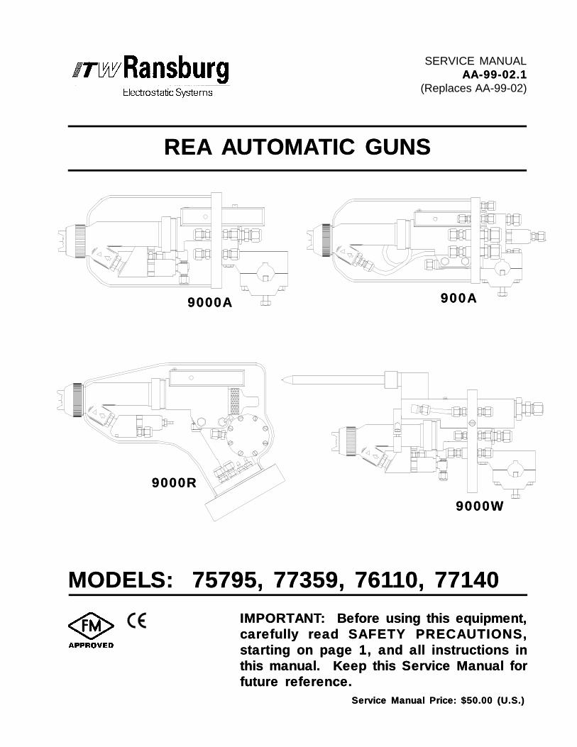
IMPORTANT: Before using this equipment,IMPORTANT: Before using this equipment,carefully read SAFETY PRECAUTIONS,carefully read SAFETY PRECAUTIONS,starting on page 1, and all instructions instarting on page 1, and all instructions inthis manual. Keep this Service Manual forthis manual. Keep this Service Manual forfuture reference.future reference.
MODELS: 75795, 77359, 761MODELS: 75795, 77359, 76110, 7714010, 77140
9000A9000A 900A900A
9000R9000R
9000W9000W
SERVICE MANUALAA-99-02.1AA-99-02.1
(Replaces AA-99-02)
REA AUTOMATIC GUNSREA AUTOMATIC GUNS
Service Manual Price: $50.00 (U.S.)Service Manual Price: $50.00 (U.S.)

NOTE:NOTE: This manual has been changed from revision AA-99-02AA-99-02 to revision AA-99-02.1 AA-99-02.1.Reasons for this change are noted under “Manual Change Summary” inside the backcover of this manual.

AA-99-02.1
REA Automatic Guns - Contents
SAFETY:SAFETY:PAGEPAGE
SAFETY PRECAUTIONS.................................................................................HAZARDS / SAFEGUARDS.............................................................................
12
CONTENTSCONTENTS
ROUTINE SCHEDULE.....................................................................................ATOMIZER ASSEMBLY CLEANING PROCEDURE......................................FLUSHING PROCEDURES.............................................................................TROUBLESHOOTING GUIDE.........................................................................SERVICE LEVEL: REA 9000A & REA 9000W SERIES...........................................................
EQUIPMENT REQUIRED....................................................................REPLACEMENT PROCEDURE..........................................................TO REMOVE GUN FROM THE WORKSITE......................................NOZZLE & ELECTRODE CLEANING / REPLACEMENT..................BARREL ASSEMBLY REMOVAL........................................................BARREL DISASSEMBLY.....................................................................BARREL REASSEMBLY......................................................................BARREL TO BODY ASSEMBLY..........................................................(9000A only) TRANSFORMER ASSEMBLY REPLACEMENT...........(9000W only) HV MODULE ASSEMBLY REPLACEMENT.................(9000A & 900A only) LOW VOLTAGE CABLE REPLACEMENT.......VALVE BODY SERVICE......................................................................AIR VALVE BODY DISASSEMBLY.....................................................RETURN THE SPRAY GUN TO THE WORK SITE...........................
REA 9000R & REA 900A SERIES...............................................................BARREL ASSEMBLY REMOVAL........................................................NOZZLE & ELECTRODE CLEANING / REPLACEMENT..................BARREL DISASSEMBLY.....................................................................BARREL REASSEMBLY......................................................................(9000R only) P-EXTENSION REMOVAL.............................................(9000R only) P-EXTENSION REPLACEMENT...................................AIR BUSHING / BODY DISASSEMBLY..............................................AIR BUSHING / BODY ASSEMBLY....................................................
18192021
23-29232323242526262727282829292930-373030313233333334
MAINTENANCE:MAINTENANCE: 18-3718-37
INTRODUCTION:INTRODUCTION:
DESCRIPTIONS...............................................................................................FEATURES........................................................................................................SPECIFICATIONS: 9000A & 9000R............................................................................................. 9000W & 900A..............................................................................................
5-135-13
57
1213
14-1714-17INSTALLATION:INSTALLATION:
TYPICAL REA AUTOMATIC GUN INSTALLATION.......................................REA ATOMIZER ASSEMBLY SELECTION TABLES.....................................
1417
1-41-4

AA-99-02.1
REA Automatic Guns - Contents
3839-6139-4243-4950-5354-5960-61
PARTS IDENTIFICATION:PARTS IDENTIFICATION:
PROCEDURE FOR ORDERING PARTS.......................................................PARTS DIAGRAM & PARTS LIST...................................................................
9000A.....................................................................................................9000R.....................................................................................................9000W....................................................................................................900A.......................................................................................................Miscellaneous Kits.................................................................................
38-6138-61
TRANSFORMER ASSEMBLY REPLACEMENT.................................(9000R only) LOW VOLTAGE CABLE REPLACEMENT....................(9000R only) LOW VOLTAGE CABLE CONNECTOR ASSEMBLY...(9000R only) LOW VOLTAGE CABLE PLUG ASSEMBLY.................
35363636
WARRANTIY POLICIES:WARRANTIY POLICIES: 6262
636466
APPENDIX:APPENDIX:
PAINT AND SOLVENT SPECIFICATIONS.....................................................VISCOSITY CONVERSION CHART...............................................................VOLUMETRIC CONTENT OF HOSE OR TUBE............................................
63-6663-66
LIMITED WARRANTY........................................................................................62

AA-99-02.1
REA Automatic Guns - Safety
11
SAFETYSAFETY
Before operating, maintaining or servicing anyITW Ransburg electrostatic coating system, readand understand all of the technical and safetyliterature for your ITW Ransburg products. Thismanual contains information that is important foryou to know and understand. This informationrelates to USER SAFETY and PREVENTINGEQUIPMENT PROBLEMS. To help you recog-nize this information, we use the following sym-bols. Please pay particular attention to thesesections.
A WARNING! states information to alert youA WARNING! states information to alert youto a situation that might cause serious injuryto a situation that might cause serious injuryif instructions are not followed.if instructions are not followed.
A CAUTION! states information that tellsA CAUTION! states information that tellshow to prevent damage to equipment or howhow to prevent damage to equipment or howto avoid a situation that might cause minorto avoid a situation that might cause minorinjury.injury.
A NOTE is information relevant to the pro-A NOTE is information relevant to the pro-cedure in progress.cedure in progress.
While this manual lists standard specificationsand service procedures, some minor deviationsmay be found between this literature and yourequipment. Differences in local codes and plantrequirements, material delivery requirements, etc.,make such variations inevitable. Compare thismanual with your system installation drawingsand appropriate ITW Ransburg equipment manu-als to reconcile such differences.
Careful study and continued use of this manual willprovide a better understanding of the equipmentand process, resulting in more efficient operation,longer trouble-free service and faster, easier trou-bleshooting. If you do not have the manuals andsafety literature for your Ransburg system, con-tact your local ITW Ransburg representative orITW Ransburg.
SAFETY PRECAUTIONSSAFETY PRECAUTIONS> The user MUST MUST read and be familiar withthe Safety Section in this manual and theITW Ransburg safety literature therein iden-tified.
> This manual MUST MUST be read and thor-oughly understood by ALL ALL personnel whooperate, clean or maintain this equipment!Special care should be taken to ensure thatthe WARNINGSWARNINGS and safety requirementsfor operating and servicing the equipmentare followed. The user should be aware ofand adhere to ALLALL local building and firecodes and ordinances as well as NFPA 33NFPA 33SAFETY STANDARD, 2000 EDITION,SAFETY STANDARD, 2000 EDITION,prior to installing, operating, and/or servic-ing this equipment.
> The hazards shown on the following pagemay occur during the normal use of thisequipment. Please read the hazard chartbeginning on page 2.
W A R N I N GW A R N I N G!
W A R N I N GW A R N I N G!
AA-99-02.1
REA Automatic Guns - Safety
22
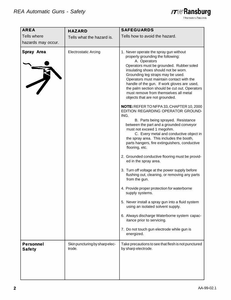
Spray AreaSpray Area Electrostatic Arcing 1. Never operate the spray gun without properly grounding the following:
A. Operators Operators must be grounded. Rubber soled insulating shoes should not be worn. Grounding leg straps may be used. Operators must maintain contact with the handle of the gun. If work gloves are used, the palm section should be cut out. Operators must remove from themselves all metal objects that are not grounded.
NOTE:NOTE: REFER TO NFPA 33, CHAPTER 10, 2000EDITION REGARDING OPERATOR GROUND-ING.
B. Parts being sprayed. Resistance between the part and a grounded conveyor must not exceed 1 megohm.
C. Every metal and conductive object in the spray area. This includes the booth, parts hangers, fire extinguishers, conductive flooring, etc.
2. Grounded conductive flooring must be provid- ed in the spray area.
3. Turn off voltage at the power supply before flushing out, cleaning, or removing any parts from the gun.
4. Provide proper protection for waterborne supply systems.
5. Never install a spray gun into a fluid system using an isolated solvent supply.
6. Always discharge Waterborne system capac- itance prior to servicing.
7. Do not touch gun electrode while gun is energized.
PersonnelPersonnelSafetySafety
Skin puncturing by sharp elec-trode.
Take precautions to see that flesh is not puncturedby sharp electrode.
AREAAREA
Tells where
hazards may occur.
HAZARDHAZARD
Tells what the hazard is.
SAFEGUARDSSAFEGUARDS
Tells how to avoid the hazard.

AA-99-02.1
REA Automatic Guns - Safety
33
Spray AreaSpray Area Fire Hazard
Improper or inadequate opera-tion and maintenance procedureswill cause a fire hazard.
Protection against inadvertentarcing that is capable of causingfire or explosion is lost if anysafety interlocks are disabledduring operation. Frequent pow-er supply shutdown indicates aproblem in the system requiringcorrection.
Fire extinguishing equipment must be present inthe spray area and tested periodically.
Spray areas must be kept clean to prevent theaccumulation of combustible residues.
Smoking must never be allowed in the spray area.
The high voltage supplied to the atomizer must beturned off prior to cleaning, flushing or mainte-nance.
When using solvents for cleaning:
Those used for equipment flushing should haveflash points equal to or higher than those of thecoating material.
Those used for general cleaning must have flashpoints above 100oF (37.8oC).
Spray booth ventilation must be kept at the ratesrequired by NFPA 33, 2000 Edition, OSHA andlocal codes. In addition, ventilation must bemaintained during cleaning operations using flam-mable or combustible solvents.
Electrostatic arcing must be prevented.
Test only in areas free of combustible material.
Testing may require high voltage to be on, but onlyas instructed.
Non-factory replacement parts or unauthorizedequipment modifications may cause fire or injury.
If used, the key switch bypass is intended for useonly during setup operations. Production shouldnever be done with safety interlocks disabled.
Never use equipment intended for use in water-borne installations to spray solvent based materi-als.
AREAAREA
Tells where
hazards may occur.
HAZARDHAZARD
Tells what the hazard is.
SAFEGUARDSSAFEGUARDS
Tells how to avoid the hazard.
AA-99-02.1
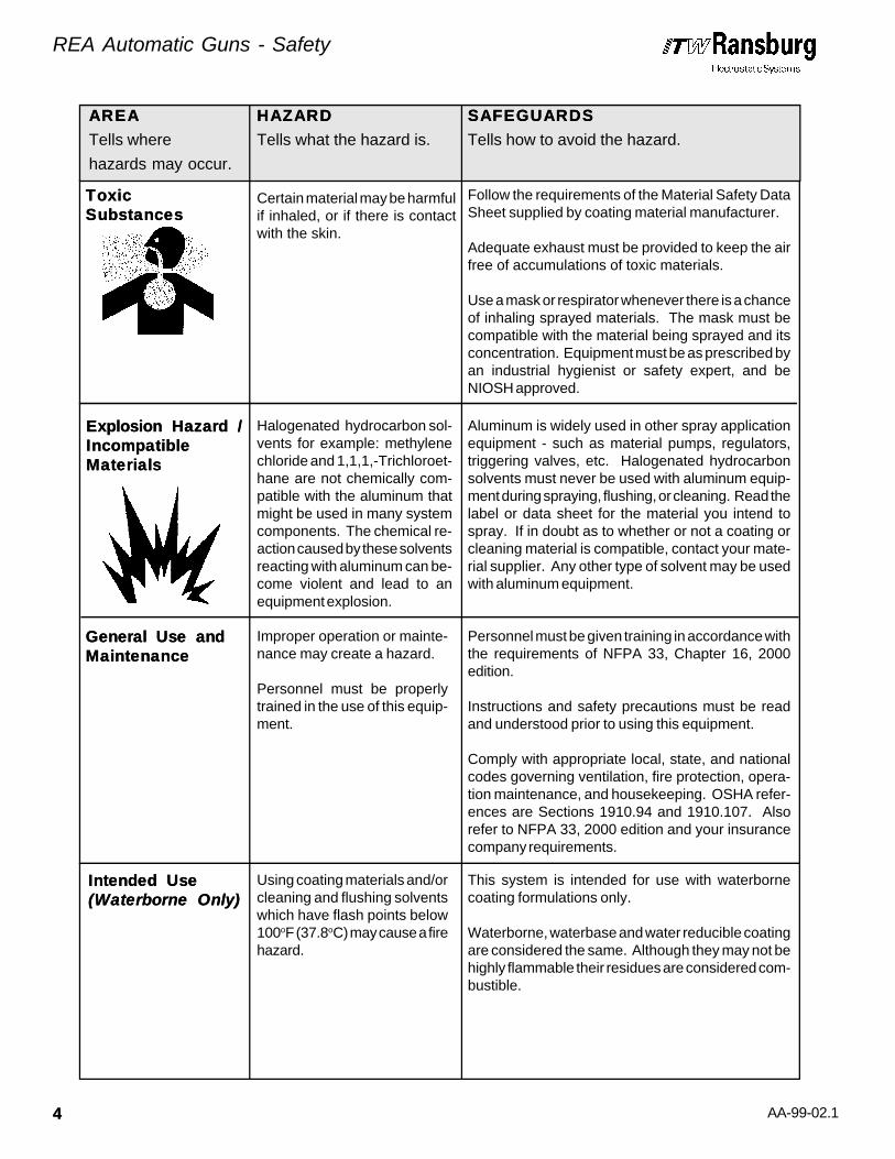
Intended UseIntended Use(Waterborne Only)(Waterborne Only)
Using coating materials and/orcleaning and flushing solventswhich have flash points below100oF (37.8oC) may cause a firehazard.
This system is intended for use with waterbornecoating formulations only.
Waterborne, waterbase and water reducible coatingare considered the same. Although they may not behighly flammable their residues are considered com-bustible.
REA Automatic Guns - Safety
44
Improper operation or mainte-nance may create a hazard.
Personnel must be properlytrained in the use of this equip-ment.
Personnel must be given training in accordance withthe requirements of NFPA 33, Chapter 16, 2000edition.
Instructions and safety precautions must be readand understood prior to using this equipment.
Comply with appropriate local, state, and nationalcodes governing ventilation, fire protection, opera-tion maintenance, and housekeeping. OSHA refer-ences are Sections 1910.94 and 1910.107. Alsorefer to NFPA 33, 2000 edition and your insurancecompany requirements.
General Use andGeneral Use andMaintenanceMaintenance
ToxicToxicSubstancesSubstances
Certain material may be harmfulif inhaled, or if there is contactwith the skin.
Follow the requirements of the Material Safety DataSheet supplied by coating material manufacturer.
Adequate exhaust must be provided to keep the airfree of accumulations of toxic materials.
Use a mask or respirator whenever there is a chanceof inhaling sprayed materials. The mask must becompatible with the material being sprayed and itsconcentration. Equipment must be as prescribed byan industrial hygienist or safety expert, and beNIOSH approved.
Explosion Hazard /Explosion Hazard /IncompatibleIncompatibleMaterialsMaterials
Halogenated hydrocarbon sol-vents for example: methylenechloride and 1,1,1,-Trichloroet-hane are not chemically com-patible with the aluminum thatmight be used in many systemcomponents. The chemical re-action caused by these solventsreacting with aluminum can be-come violent and lead to anequipment explosion.
Aluminum is widely used in other spray applicationequipment - such as material pumps, regulators,triggering valves, etc. Halogenated hydrocarbonsolvents must never be used with aluminum equip-ment during spraying, flushing, or cleaning. Read thelabel or data sheet for the material you intend tospray. If in doubt as to whether or not a coating orcleaning material is compatible, contact your mate-rial supplier. Any other type of solvent may be usedwith aluminum equipment.
AREAAREA
Tells where
hazards may occur.
HAZARDHAZARD
Tells what the hazard is.
SAFEGUARDSSAFEGUARDS
Tells how to avoid the hazard.

AA-99-02.1
REA Automatic Guns - Introduction
55
INTRODUCTIONINTRODUCTION
The REA Automatic processes are an air atom-ized method for electrostatically applying coatingsto objects. The REA Automatics apply a highvoltage DC charge to the applicator electrode,creating an electrostatic field between the atomiz-er and the target object. The target is electricallygrounded through its support which may be eitherstationary or moving.
A regulated pressure fluid system delivers mate-rial to the atomizer. At the time of triggering theapplicators fan and atomization air is applied whichatomizes the material forming a spray mist. Themist under the influence of the electrostatic field,becomes electrically charged. The charged par-ticles of material are attracted to, and depositedon, the target. The forces between the chargedparticles and the grounded target are sufficient toturn most normal overspray around and deposit iton the back surface of the target. Therefore, ahigh percentage of the spray is deposited on thetarget.
One of the many features of the REA Gun Auto-matic System is the electrical discharge which isavailable from the resistive charging electrode islimited to the optimum level of safety and efficien-cy.
As the gun electrode approaches ground, thecontrol unit and gun circuitry shut down the highvoltage and current to the gun. The control unitmust then be reset to continue to spray electro-statically.
The REA Automatic Electrostatic Spray Guns aretransformable between air spray and HVLP spraytechnology. By changing a select few parts, thegun may be transformed to be operated in eitherspray mode. (See Spray Technology ConversionProcedure, in the INSTALLATION section of thismanual for details.)
The REA 9000AThe REA 9000A has an integral trigger anddump valve built into the design. This preventsspits
and drips normally associated with guns of thisdesign.
The trigger valve mounted at the inlet of the REA9000A gun allows minimal spray into the boothduring a color change sequence. Only the con-tents of paint from the trigger valve to the nozzlemust be cleaned. Then by activating the dumpvalve, the rest of the waste material may betransported to an alternate collection means. Sincethis material is not sprayed in the booth, the VOC'semitted are reduced significantly.
The REA900A Gun is designed with a movingtrigger (shaft), so no forward mounted triggervalve is required. The dump valve is mounted onthe rear bulkhead plate for ease of maintenance.All fluid connections in this gun use "AN" stylefittings to eliminate "dead spots" in the fluid path forsuperior flushing.
The REA 9000RThe REA 9000R is a robot-mounted gun forhollow wrist robots produced by either FANUC orABB. The advantage of the REA 9000R gun is thatit can be removed quickly and easily from the robotmounting plate with the use of a threaded retainingring.
The REA 9000R incorporates two important safe-ty features. The first being a breakaway designthat will shear (2) nylon mounting bolts if the guncomes in contact with the object being sprayed.The second is the discharge which is availablefrom the resistive charging electrode is limited tothe optimum level of safety and efficiency.
The REA 9000WThe REA 9000W is an external charge probegun designed to spray waterborne coatings insystems utilizing a grounded fluid supply. Gunfeatures include: Probe Shroud Air and ElectrodeShroud Air. Low pressure air exiting around theprobe body and electrode wire aid in keepingthese components clean during operation. Thesefeatures help to maintain maximum efficiency ofthe guns over a longer period of time. The REA9000W gun also offers conventional “classic” highvoltage technology.
DESCRIPTIONSDESCRIPTIONS

AA-99-02.1
REA Automatic Guns - Introduction
66
The REA 9000A, 9000R and 900A SeriesThe REA 9000A, 9000R and 900A Seriesof gunsof guns apply -85 kV DC charge to the coatingmaterials at the point of atomization. This series ofguns is intended for use with grounded solvent-borne coating systems. The REA 9000W Seriesof guns applies -70 kV DC charge. This electro-static charge allows a more efficient, uniformapplication of coating material to the front, edges,sides, and back of products. It is highly suitable forapplying coatings to a variety of surface configu-rations: large targets, small parts, tubular wares,concave and recessed parts, etc. keeping thesecomponents clean during operation. These fea-tures help to maintain maximum efficiency of theguns over a longer period of time.
These series of guns include the automatic gun,low or high voltage cable, control unit, fluid hoseand air tubing.
The control unit provides voltage output to the gunand contains controls for AC on/off, high voltageadjust, kV/microamp meter and triple set point oranalog input control.
NOTES:NOTES:

AA-99-02.1
REA Automatic Guns - Introduction
77
Figure 1b: View of Back PlateFigure 1b: View of Back Plate
Figure 1a: REA 9000A Solventborne Electrostatic Spray GunFigure 1a: REA 9000A Solventborne Electrostatic Spray Gun

AA-99-02.1
REA Automatic Guns - Introduction
88
Figure 2b: View of Mounting Plate AssemblyFigure 2b: View of Mounting Plate Assembly
Figure 2a: REA 9000R Solventborne Electrostatic Spray GunFigure 2a: REA 9000R Solventborne Electrostatic Spray Gun

AA-99-02.1
REA Automatic Guns - Introduction
99
Figure 4: Adapter PlatesFigure 4: Adapter Plates
Figure 3: Gun Tool-Point RepresentationFigure 3: Gun Tool-Point RepresentationREA 9000R AutomaticREA 9000R Automatic
76110 REA 9000R 60o 12.25 6.5076110 REA 9000R 90o 10.00 7.50
X X Y Y
For use with Fanuc P-200 Robots, the following adapter plates must be used:
EO-3150-121-014 is for 100o wrist.EO-3461-127-001 is for 140o wrist.
>> To allow for ease of configuration,operation, and modification of robot teachpatterns, the following X/Y vertices areprovided. (Refer to Figure 3 for explana-tion of coordinates). Optimum spraypattern is achieved at a distance of 10 -14 inches from tip.
NOTENOTE

AA-99-02.1
REA Automatic Guns - Introduction
1010
Figure 5b: View of Back PlateFigure 5b: View of Back Plate
Figure 5a: REA 9000W Waterborne Electrostatic Spray GunFigure 5a: REA 9000W Waterborne Electrostatic Spray Gun
AA-99-02.1
REA Automatic Guns - Introduction
1111
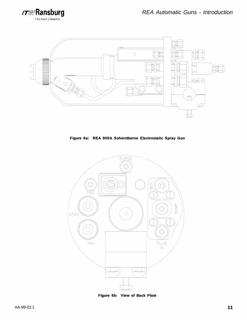
Figure 6a: REA 900A Solventborne Electrostatic Spray GunFigure 6a: REA 900A Solventborne Electrostatic Spray Gun
Figure 6b: View of Back PlateFigure 6b: View of Back Plate

AA-99-02.1
REA Automatic Guns - Introduction
1212
SPECIFICASPECIFICATIONS -TIONS -SOLSOLVENTBORNE REAVENTBORNE REA 9000A 9000A
Operating Voltage:Operating Voltage: 85 kV DC [-] maximumCurrent Output:Current Output: 120 microamperes
maximum
Weight:Weight: 70 oz. (2,100g)Gun Diameter:Gun Diameter: 5.25" (13.3cm)Gun Length:Gun Length: 13.0" (33.0cm)
Center Distance from Mount to:Center Distance from Mount to: Nozzle End 11.8" (29.9cm) Center Line of Nozzle 1.9" (4.8cm)Cable Lengths:Cable Lengths: 36 feet
[optional: 50, 75 and 100 feet]
Atomizer Assembly:Atomizer Assembly: 4904-65R 4907-45 HVLP 75600-01 HVLP 75601-00
Fluid Flow Rate:Fluid Flow Rate: Variable to 1,000 cc/minuteOperating Pressure: [Air Spray]Operating Pressure: [Air Spray] Fluid 0-100 psi (6.8 bar) Air 0-100 psi (6.8 bar) Consumption 16 scfm @ 50 psigOperating Pressure: [HVLP Spray]Operating Pressure: [HVLP Spray] Fluid 0-100 psi (6.8 bar) Air 0-100 psi (6.8 bar) Consumption 22 scfm @ 50 psig
[input] for 10 psi nozzle output
Atomization Air InletAtomization Air InletSize:Size: 3/8" NPT (F) (1/4"
NPT) (F) 3/8" ODTFan Air InletFan Air InletSize:Size: 3/8" NPT (F) (1/4"
NPT) (F) 3/8" ODTFluid Inlet Size:Fluid Inlet Size: 1/4" NPT (F)Gun Mounting Stud:Gun Mounting Stud:Diameter:Diameter: .98"-1.00" (25mm-
27mm)Trigger Actuation:Trigger Actuation: 1/4"ODT - 1/8"NPT (F)Dump Actuation:Dump Actuation: 1/4"ODT - 1/8"NPT (F)Fluid Dump Out:Fluid Dump Out: 1/4"ODT - 1/4"NPT (F)Shroud Purge Line:Shroud Purge Line: 1/4"ODT - 1/8"NPT (F)Woodruf Key MountWoodruf Key MountSize:Size: 1/4" Nominal*Paint Resistance:*Paint Resistance: .1 MΩ to ∞
Figure 7: REA 9000A SpecificationsFigure 7: REA 9000A Specifications
SPECIFICASPECIFICATIONS -TIONS -SOLSOLVENTBORNE REAVENTBORNE REA 9000R 9000R
Operating Voltage:Operating Voltage: 85 kV DC [-] maximumCurrent Output:Current Output: 120 microamperes
maximum
Weight:Weight: 41 oz. (1,162g)Gun Height:Gun Height: 6.5" (33.66cm)Gun Length:Gun Length: 13.25" (33.66cm)Gun Width:Gun Width: 2" (5.08cm)Cable Lengths:Cable Lengths: 36 feet
[optional: 50, 75 and 100 feet]
Atomizer Assembly:Atomizer Assembly: 4904-65R 4907-45 HVLP 75600-01 HVLP 75601-00
Fluid Flow Rate:Fluid Flow Rate: Variable to 1,000 cc/minuteOperating Pressure: [Air Spray]Operating Pressure: [Air Spray] Atomizing Air 0-100 psig (6.8 bar) Fan Air 0-100 psig (6.8 bar) Trigger Air 40 psig Min. (2.7 bar)
100 psig Max. (6.8 bar) Fluid 0-100 psig (6.8 bar)Operating Pressure: [HVLP Spray]Operating Pressure: [HVLP Spray] Atomizing Air 0-100 psig (6.8 bar) Fan Air 0-100 psig (6.8 bar) Trigger Air 40 psig Min. (2.7 bar)
100 psig Max. (6.8 bar) Fluid 0-100 psig (6.8 bar)Piston Air InletPiston Air InletSize:Size: 3/16" ODTAtomization Air InletAtomization Air InletSize:Size: 3/8" ODTFan Air Inlet Size:Fan Air Inlet Size: 3/8" ODTFluid Inlet Size:Fluid Inlet Size: 1/4" ODT*Paint Resistance:*Paint Resistance: .1 MΩ to ∞
Figure 8: REA 9000R SpecificationsFigure 8: REA 9000R Specifications
Electrical / PhysicalElectrical / Physical Electrical / PhysicalElectrical / Physical
*(Ransburg Meter)

AA-99-02.1
REA Automatic Guns - Introduction
1313
SPECIFICASPECIFICATIONS -TIONS -WAWATERBORNE REATERBORNE REA 9000W 9000W
Operating Voltage:Operating Voltage: 70 kV DC [-] Max.Current Output:Current Output: 120 microamperes Max.
(Classic)Weight:Weight: 82 oz. (2,325g)Bulkhead Diameter:Bulkhead Diameter: 6.69" (16.9cm)Max Gun Height:Max Gun Height: 7.90" (20.0cm)Gun Length:Gun Length: 16.51" (33.0cm)Center Distance from Mount to:Center Distance from Mount to: Probe End 15.23" (38.6cm) Nozzle End 11.80" (29.9cm) Center Line of Nozzle 1.90" (4.8cm) Center Line of Probe 5.92" (15.0cm)Cable Lengths:Cable Lengths: Classic Version 100 feet Max.
[SSW-1064 HVCable]Atomizer Assembly:Atomizer Assembly: 4904-65R
4907-45 HVLP 75600-01 HVLP 75601-00
Fluid Flow Rate:Fluid Flow Rate: Variable to 1,000 cc/minuteOperating Pressure: [Air Spray]Operating Pressure: [Air Spray] Fluid 0-100 psi (6.8 bar) Air 0-100 psi (6.8 bar) Consumption 16 scfm @ 50 psigOperating Pressure: [HVLP Spray]Operating Pressure: [HVLP Spray] Fluid 0-100 psig (6.8 bar) Air 0-100 psig (6.8 bar) Consumption 22 scfm @ 50 psig
[input] for 10 psig nozzle output
Atomization Air InletAtomization Air InletSize:Size: 3/8" NPT (F) 1/4" NPT
(F) 3/8"ODTFan Air InletFan Air InletSize:Size: 3/8" NPT (F) 1/4" NPT
(F) 3/8"ODTFluid Inlet Size:Fluid Inlet Size: 1/4" AN (F) 1/4" ODTDump Outlet Size:Dump Outlet Size: 1/4" AN(F) 3/8" ODTTrigger Actuation:Trigger Actuation: 1/4"ODT - 1/8"NPT (F)Dump Actuation:Dump Actuation: 1/4"ODT - 1/8"NPT (F)Probe Shroud/KnifeProbe Shroud/KnifeAir:Air: 1/4"ODT - 1/8"NPT (F)Shroud/Gun CoverShroud/Gun CoverPurge Air:Purge Air: 1/4"ODT - 1/8"NPT (F)Gun Mounting StudGun Mounting StudDiameter:Diameter: .98" - 1.00"Mount Woodruf KeyMount Woodruf KeySize:Size: 1/4" Nominal
Figure 9: REA 9000W SpecificationsFigure 9: REA 9000W Specifications
SPECIFICASPECIFICATIONS -TIONS -SOLSOLVENTBORNE REAVENTBORNE REA 900A 900A
Figure 10: REA 900A SpecificationsFigure 10: REA 900A Specifications
Electrical / PhysicalElectrical / Physical Electrical / PhysicalElectrical / PhysicalOperating Voltage:Operating Voltage: 85 kV DC [-] maximumCurrent Output:Current Output: 120 microamperes
maximumWeight:Weight: 84 oz. (2,100g)Gun Diameter:Gun Diameter: 5.50" (13.9cm)Gun Length:Gun Length: 14.85" (37.6cm)Center Distance from Mount to:Center Distance from Mount to: Nozzle End 13.00" (32.9cm) Center Line of Nozzle 1.90" (4.8cm)Cable Lengths:Cable Lengths: 36 feet(std)
[optional: 50, 75 and 100 feet]
Atomizer Assembly:Atomizer Assembly: 4904-65R 4907-45 HVLP 75600-01 HVLP 75601-00
Fluid Flow Rate:Fluid Flow Rate: Variable to 1,000 cc/minuteOperating Pressure [Air Spray]Operating Pressure [Air Spray] Fluid 0-100 psig (6.8 bar) Air 0-100 psig (6.8 bar) Consumption 16 scfm @ 50 psigOperating Pressure [HVLP Spray]Operating Pressure [HVLP Spray] Fluid 0-100 psi (6.8 bar) Air 0-100 psi (6.8 bar) Consumption 22 scfm @ 50 psig
[input] for 10 psig nozzle output
Atomization Air InletAtomization Air InletSize:Size: 1/4" NPT (F) 1/2" ODTFan Air InletFan Air InletSize:Size: 1/4" NPT (F) 1/2" ODTFluid Inlet Size:Fluid Inlet Size: 1/4" AN (F) 1/4" ODTDump Outlet Size:Dump Outlet Size: 1/4" AN (F) 3/8" ODTTrigger Actuation:Trigger Actuation: 1/8" NPT (F) 1/4" ODTDump Actuation:Dump Actuation: 1/8" NPT (F) 1/4" ODTShroud Purge Air:Shroud Purge Air: 1/8" NPT (F) 1/4" ODTGun Mounting StudGun Mounting StudDiameter:Diameter: .98" - 1.00"Mount Woodruf KeyMount Woodruf KeySize:Size: 1/4" Nominal*Paint Resistance: *Paint Resistance: . 1 MΩ to ∞
*(Ransburg Meter)
AA-99-02.1
REA Automatic Guns - Installation
1414
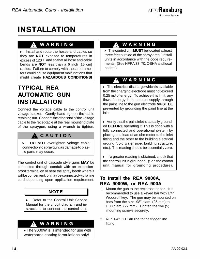
Connect the voltage cable to the control unitvoltage socket. Gently hand tighten the cableretaining nut. Connect the other end of the voltagecable to the receptacle at the rear mounting plateof the spraygun, using a wrench to tighten.
The control unit of cascade style guns MAY MAY beconnected through conduit with an explosion-proof terminal on or near the spray booth where itwill be convenient, or may be connected with a linecord depending upon application requirement.
>> Refer to the Control Unit ServiceManual for the circuit diagram and in-structions to connect the control unit.
1. Mount the gun to the reciprocator bar. It is recommended to use a keyed bar with 1/4" Woodruff key. The gun may be mounted on bars from the size .98" diam. (25 mm) to 1.00 diam. (27 mm). Tighten the five (5) mounting screws securely.
2. Run 1/4" ODT air line to the trigger line fitting.
INSTALLATIONINSTALLATION
W A R N I N GW A R N I N G!
> Install and route the hoses and cables sothey are NOT NOT exposed to temperatures inexcess of 120°F and so that all hose and cablebends are NOTNOT less than a 6 inch [15 cm]radius. Failure to comply with these parame-ters could cause equipment malfunctions thatmight create HAZARDOUS CONDITIONS!HAZARDOUS CONDITIONS!
W A R N I N GW A R N I N G!> The control unit MUSTMUST be located at leastthree feet outside of the spray area. Installunits in accordance with the code require-ments. (See NFPA 33, 70, OSHA and localcodes.)
W A R N I N GW A R N I N G!
TYPICAL REATYPICAL REAAUTAUTOMAOMATIC GUNTIC GUNINSTINSTALLAALLATIONTION
> DO NOTDO NOT overtighten voltage cableconnection to spraygun, as damage to plas-tic parts may occur.
NOTENOTE
> The electrical discharge which is availablefrom the charging electrode must not exceed0.25 mJ of energy. To achieve this limit, anyflow of energy from the paint supply throughthe paint line to the gun electrode MUST BEMUST BEprevented by grounding the paint line at theinlet.
> Verify that the paint inlet is actually ground-ed BEFOREBEFORE operating it! This is done with afully connected and operational system byplacing one lead of an ohmmeter to the inletfitting and the other to the building electricalground (cold water pipe, building structure,etc.). The reading should be essentially zero.
> If a greater reading is obtained, check thatthe control unit is grounded. (See the controlunit manual for grounding procedure).
To Install the REA 9000A,To Install the REA 9000A,REA 9000W, or REA 900AREA 9000W, or REA 900A
C A U T I O NC A U T I O N!
> The 9000W is is intended for use withwaterborne coating formulations only!
W A R N I N GW A R N I N G!

AA-99-02.1
REA Automatic Guns - Installation
1515
>> All fittings except the REA 9000A’sfluid inlet fitting may be replaced withalternate fittings, depending on your in-stallation. (See SPECIFICATIONS pre-viously discussed in the INTRODUC-TION section, for female thread size.
3. Run 3/8" ODT or 1/2" ODT fluid line to the gun.
4. Connect atomization air and fan air lines. Depending upon atomization technology used, size the line accordingly.
5. Install 1/4" ODT air line to shroud or probe purge air. Set pressure between 5-10 psig.
Figure 11: Typical Fluid Filter InstallationFigure 11: Typical Fluid Filter Installation
FiltersFilters
1. Install a fluid filter on the output of fluid supply, as shown in Figure 11 below.
2. Detail depends on whether pressure tank, pump unit, recirculating system, etc., is used. The filter must be installed vertically with drain valve down and arrow pointing in direction of flow.
A proper paint mixture is essential to electrostaticoperation. Paint test equipment may be obtainedthrough your ITW Ransburg representative. Con-sult ITW Ransburg Paint Related Information forREA and REM Guns Manual, for paint formulationinformation. For further paint formulation andtesting procedures, consult your ITW Ransburgrepresentative and/or your paint supplier.
6. Install 1/4" ODT air line for dump actuation.
7. Install 3/8" ODT Teflon® fluid line to dump out.
NOTENOTE> Failure to use Teflon dump line will degradecolor change time and gun performance.
>> For optimum finish quality use clean,dry filtered air.
NOTENOTE
C A U T I O NC A U T I O N!
> Whenever the gun is in the dump or flushmode, the electrostatics must be off.
W A R N I N GW A R N I N G!
Paint PreparationPaint Preparation
> Failure to connect the shroud purge air line onthe REA 9000A and REA 900A Guns can allowexcessive corona to build up within the shroudand cause premature failure of the barrel andtransformer assemblies.
C A U T I O NC A U T I O N!
>> The atomization and fan air line shouldalways lead the trigger signal when thegun is on, and lag the trigger signal whenthe gun is off. Failure to follow thisprocedure will cause gun spits.
NOTENOTE
> ALLALL fittings exceptexcept the REA 9000Afluid inlet fitting used must be nonconduc-tive. The use of electrical conductivefitting may cause injury or fire.
W A R N I N GW A R N I N G!
FluidFilter
To Applicator
From PaintSupply
DrainValve

AA-99-02.1
REA Automatic Guns - Installation
1616
Remove existing retaining ring and air cap fromend of gun. Remove fluid nozzle using gun wrench19749-00.
With a bladed screwdriver, remove pressure re-ducers by turning counter clockwise from barrel.Install the desired pressure reducer. Apply suit-able liquid Teflon pipe thread sealant to threads.Install appropriate fluid nozzle, gently tighteninginto place using the gun wrench 19749-00. Rein-stall appropriate air cap and retaining ring. (SeeNozzle Selection Chart, Figure 12 later in thissection, for proper combination of air caps, fluidnozzles and pressure reducers).
For remote HVLP fan air applications fan control,air pressure should not exceed 10 psi. Fan controlpressure should be adjusted depending upon pat-tern size desired.
The Atomizer Assembly Selection Chart is provid-ed to give you a comparison of the air caps andfluid nozzles. THE CHOICE OF ATOMIZERTHE CHOICE OF ATOMIZERASSEMBLY SHOULD DEPEND ON QUAL-ASSEMBLY SHOULD DEPEND ON QUAL-ITIES DESIRED AND MUST BE VERIFIEDITIES DESIRED AND MUST BE VERIFIEDBY ACTUAL TRIAL. BY ACTUAL TRIAL. See your authorized ITWRansburg electrostatic distributor for atomizerdemonstration.
Mount the gun six to twelve inches maximum fromthe target for best operation. (A higher transferefficiency will be achieved at the closer targetdistance).
The cable from the control unit of the REA 9000Rshould be run through suitable conduit and con-nected at the robot explosion proof enclosure, ifnecessary.
Spray Technology ConversionSpray Technology ConversionProcedureProcedure
> To avoid damage to the fluid nozzle andelectrode, the paint pressure and trigger returnspring tension MUST MUST be released by trigger-ing the gun prior to removing the fluid nozzle.
> The gun MUST MUST be tilted front down toremove the fluid nozzle. Failure to do so mayallow paint to enter the air passages, therebyreducing air flow and damaging the gun barrelor cause electrical shorting. Guns may beflushed in lieu of tilting, but they MUST MUST beeither flushed or tilted BEFOREBEFORE removing thefluid nozzle!
C A U T I O NC A U T I O N!
Atomizer Assembly SelectionAtomizer Assembly Selection
The spray pattern of fan atomizers is adjustablefrom a small circle to an elongated oval, approxi-mately ten to eighteen inches across the usablelong axis at eight to twelve inches from the target.The swirl atomizer assemblies produce a roundpattern from five to nine inches in diameter. Toadjust pattern size, increasing fan air pressure willexpand the pattern, a reduction will decrease it. Tochange the spray pattern axis of fan atomizersfrom horizontal to vertical, loosen retainer ring,rotate the air cap clockwise to the desired positionand gently tighten the ring.
Spray Pattern AdjustmentSpray Pattern Adjustment
> A counterclockwise turn of the air cap mayloosen the Fluid Nozzle and cause air to get intothe paint or paint to cross over into the airpassages.
C A U T I O NC A U T I O N!
Gun To Target DistanceGun To Target Distance
The REA 9000R comes with a complete cablefrom the mounting plate.
> If the REA 9000R cable must be terminatedat the robot, it must be done within a suitableexplosion proof enclosure.
Wiring The UnitWiring The Unit
W A R N I N GW A R N I N G!

AA-99-02.1
REA Automatic Guns - Installation
1717
Figure 12: Atomizer Assembly SelectionFigure 12: Atomizer Assembly Selection
REA NOZZLESREA NOZZLES[Conventional Spray][Conventional Spray]
Air CapAir Cap Separate Separate Pressure Pressure Part Part Fluid Nozzle Fluid Nozzle Oriface Oriface Retaining Retaining Reducer ReducerNumberNumber Part Number Part Number I.D. I.D. Ring Ring [Black] [Black]
70899-00 70898-00 Swirl 4903-00 74963-02LREA0002 LREA0003 Round 73569-00 74963-02 4904-65R 4907-44 .055 73569-00 74963-02 4904-65R 4907-45 .070 73569-00 74963-02 4904-65R 4907-46 .042 73569-00 74963-02 4904-65R 4907-47 .028 73569-00 74963-024904-65R 4907-48 .047 73569-00 74963-02 4904-63 4907-44 .055 73569-00 74963-02 4904-63 4907-45 .070 73569-00 74963-02 4904-63 4907-46 .042 73569-00 74963-02 4904-63 4907-47 .028 73569-00 74963-02 4904-63 4907-48 .047 73569-00 74963-02 4904-98 4907-44 .055 73569-00 74963-02 4904-98 4907-45 .070 73569-00 74963-02 4904-98 4907-46 .042 73569-00 74963-02 4904-98 4907-47 .028 73569-00 74963-02 4904-98 4907-48 .047 73569-00 74963-02
REA NOZZLESREA NOZZLES[HVLP][HVLP]
Air CapAir Cap Separate Separate Pressure Pressure Part Part Fluid Nozzle Fluid Nozzle Oriface Oriface Retaining Retaining Reducer ReducerNumberNumber Part Number Part Number I.D. I.D. Ring Ring [White] [White]
75601-00 75600-01 .055 73569-00 74963-0375601-00 75600-02 .070 73569-00 74963-0375601-00 75600-03 .086 73569-00 74963-03

AA-99-02.1
REA Automatic Guns - Maintenance
1818
> NEVER NEVER remove the fluid nozzle assemblywhile paint is in the gun or paint may clog theair passages. Clogged air passages willcause poor atomization and electrical short-ing. Air passages which are clogged withconductive material may lead to excessivecurrent output levels and consequent lowoperating voltage and long range electricaldamage. Before undertaking any atomizerassembly procedure, see Atomizer Assem-Atomizer Assem-bly Cleaning Procedure.bly Cleaning Procedure.
> The gun MUSTMUST be tilted front down toremove the air cap and/or fluid nozzle. Failureto do so may allow paint to enter the airpassages, thereby reducing air flow and dam-aging the gun barrel/cascade. Guns may beflushed in lieu of tilting. However, they mustbe either flushed or tilted down!
> NEVER NEVER soak or submerge the electricalcomponents of the gun (i.e. barrel, transformer,cable). Damage and failure may occur.
> The user MUST MUST read and be familiar withthe SAFETY INSTRUCTIONS SAFETY INSTRUCTIONS in this man-ual.
> If compressed air is used in cleaning,REMEMBER THAT HIGH PRESSUREREMEMBER THAT HIGH PRESSUREAIR CAN BE DANGEROUS ANDAIR CAN BE DANGEROUS ANDSHOULD NEVER BE USED AGAINSTSHOULD NEVER BE USED AGAINSTTHE BODY. THE BODY. It can blind, deafen and mayeven penetrate the skin. If used for cleaningequipment, the users should wear safety glass-es.
> ALWAYSALWAYS turn the control unit power offprior to cleaning or servicing equipment.
> Be SURESURE the power is OFFOFF and thesystem is grounded BEFOREBEFORE using solventto clean ANYANY of the equipment.
> DO NOT OPERATE A FAULTY GUN!DO NOT OPERATE A FAULTY GUN!
> When using cleaning solvent, standardhealth and safety precautions should apply.
MAINTENANCEMAINTENANCE
Several Times DailySeveral Times Daily•• Turn the control unit power to OFF!
•• Inspect the air cap for paint accumulation. Clean as frequently as necessary with a soft bristled brush and a suitable solvent, and blow clean.
W A R N I N GW A R N I N G!
ROUTINE SCHEDULEROUTINE SCHEDULEFollow these maintenance steps to extend the lifeof the gun and insure efficient operation.
C A U T I O NC A U T I O N!
•• Clean all insulating surfaces in the system. Remove paint accumulation from the exterior of the gun, low voltage cable and air lines with a solvent dampened cloth. Use only nonpolar (nonconductive) solvent.
W A R N I N GW A R N I N G!
•• Verify that ALL solvent safety containers are grounded!
• • Check within 20 feet of the point of operation (of the gun) and remove or ground ALL loose or ungrounded objects.
• • Inspect workholders for accumulated coating materials, removing such accumulations.
Daily (at the start of each shift)Daily (at the start of each shift)

AA-99-02.1
REA Automatic Guns - Maintenance
1919
> If the coating material is fast settling and if thelines are not flushed soon enough, the gun'sfluid passages as well as the lines may becomeclogged and cause excessive down time and/orservice and repair.
> When straightening the electrode, be carefulnot to distort the fluid nozzle orifice.
1. Turn the paint supply OFF.
2. Turn high voltage on at gun.
3. Slowly approach the gun electrode to any grounded object and make contact.
4. Monitor the current output reading on the voltage supply meter. As gun approaches ground current should increase near 100 µA overload current should "trip," shutting "off" high voltage. Overload indication should come on.
5. Release the trigger and turn the control unit power OFF.
If the control unit does not trip, DO NOT use thegun until the problem has been corrected. (Seethe TROUBLESHOOTING GUIDE in the MAIN-TENANCE section of this manual).
WeeklyWeekly• • Check the entire system for damage, leaks and paint accumulation.
• • Clean the atomizer assembly.
Routine Cleaning EquipmentRoutine Cleaning EquipmentNeededNeeded• • An appropriate nonpolar (nonconductive) solvent.• • A solvent safety container (grounded).• • A small soft-bristled brush.• • The ITW Ransburg 19749-00 special Multi- Purpose Wrench from the Installation Kit.
• • Check that atomizer assembly is clean and undamaged.
• • Straighten the gun electrode if necessary.
C A U T I O NC A U T I O N!
• • Clean the fluid filter, if used.
• • Turn the control unit power ON. The gun's red transformer light should light when triggered.
• • Run a current/voltage output test.
Electrical Current Output TestElectrical Current Output Test
1. Turn the control unit power OFF.
2. Turn the paint supply OFF.
3. Turn the atomizing air and fan air OFF.
Shut-DownShut-Down(and at the end of each shift)(and at the end of each shift)
4. Wipe the gun, cable and hoses with a rag and a suitable nonpolar (nonconductive) sol- vent.
5. Flush the lines and allow the solvent to remain in the lines unpressured. (See FLUSHING PROCEDURES in the MAIN- TENANCE section of this manual).
C A U T I O NC A U T I O N!
ATATOMIZER ASSEMBLOMIZER ASSEMBLYYCLEANING PROCEDURECLEANING PROCEDURE
> If the shutdown is to be short, the linesmay not require flushing, depending onthe coating material being used. If thesolids in the material settle slowly, thelines will not need to be flushed as soonafter shut-down as with fast settlingsolids. The paint being used and thelength of time that the lines will be shutdown will determine the need for flush-ing. Metallic paint and primer will requireflushing sooner than some other kindsof coating materials.
NOTENOTE

AA-99-02.1
REA Automatic Guns - Maintenance
2020
> To avoid damage to the fluid nozzle, needle/electrode, the paint pressure MUSTMUST be re-leased by triggering the gun prior to removingthe tip.
> The gun MUST MUST be tilted front down toremove the air cap and/or fluid nozzle. Failureto do so may allow paint to enter the airpassages, thereby reducing air flow and dam-aging the gun barrel/cascade. Guns may beflushed in lieu of removing nozzles. However,they must be either flushed prior to, or tilteddown during nozzle removal!
> The control unit power MUST MUST always be offwhen removing the nozzles or any other ser-vice to the gun.
> Using any tool other than the ITW Ransburg19749-00 wrench to remove or reinstall thefluid nozzle may distort or damage it.
For efficient operation, keep the gun's exterior andthe voltage cable clean and free of paint accumu-lation and dirt. This prevents the loss of voltage toground with a resulting reduction in electrostaticeffect. Paint accumulation at the air cap orificesreduces atomization quality and increases thepotential for paint spits. Clean the air cap with abrush and solvent as often as needed to insuregood atomization.
5. Clean the removed parts with a soft brush and suitable solvent.
1. Turn the control unit power OFF.
2. Release the trigger.
> NEVERNEVER wrap the gun in plastic to keep itclean. A surface charge may build-up on theplastic surface and discharge to the nearestgrounded object. Efficiency of the gun will alsobe reduced and damage or failure of the guncomponents may occur. WRAPPING THE WRAPPING THEGUN IN PLASTIC WILL VOID WARRAN-GUN IN PLASTIC WILL VOID WARRAN-TY.TY.
1. Turn the control unit power OFF.
2. Turn the paint supply OFF.
3. Turn the atomizing air supply OFF.
4. Activate dump air and flush with solvent until it is clear of paint. Air purge the dump line.
5. De-activate dump air and activate trigger air until the gun fluid passage is clear.
6. Disconnect the solvent supply.
7. Activate the trigger valve until it is clear of solvent. After the preceding steps are complete, the gun is ready for color change, storage or service.
C A U T I O NC A U T I O N!
W A R N I N GW A R N I N G!
Proceed as follows:Proceed as follows:
FLUSHING PROCEDURESFLUSHING PROCEDURES
> Any damage to the gun may result inUNSAFEUNSAFE operating.
> Metal tools and wire brushes must NEV-NEV-ERER be used. NEVERNEVER use a cleaning toolthat is harder than the plastic parts. If adeposit cannot be removed with solvent anda rag or soft brush, soak the part in the solventONLYONLY until the deposit can be removed!NEVER SOAK THE GUN BODY, BAR-NEVER SOAK THE GUN BODY, BAR-REL, OR TRANSFORMER!REL, OR TRANSFORMER!
C A U T I O NC A U T I O N!
! W A R N I N GW A R N I N G
3. Turn the paint flow OFF.
4. See SERVICE section of this manual for disassembly procedures.
AA-99-02.1
REA Automatic Guns - Maintenance
2121
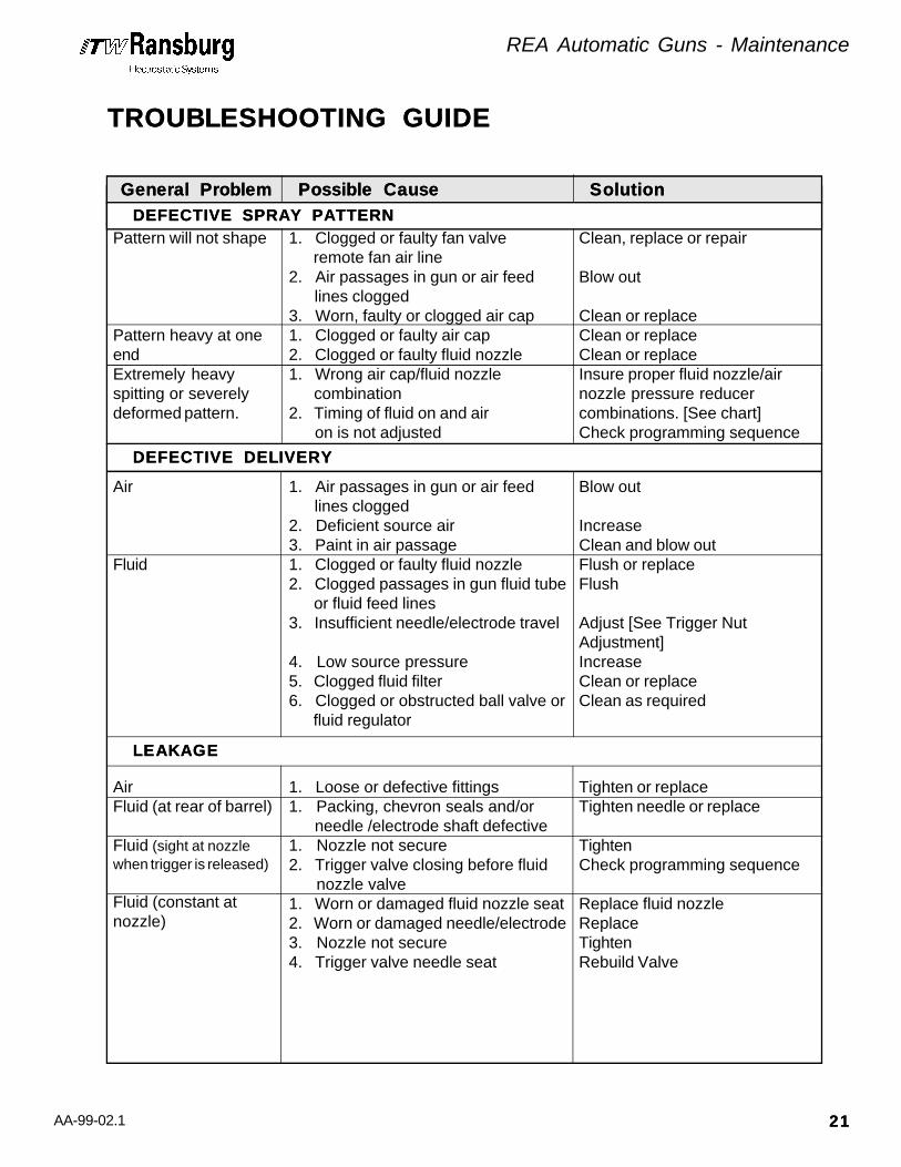
TROUBLESHOOTING GUIDETROUBLESHOOTING GUIDE
Pattern will not shape
Pattern heavy at oneendExtremely heavyspitting or severelydeformed pattern.
1. Clogged or faulty fan valve remote fan air line2. Air passages in gun or air feed lines clogged3. Worn, faulty or clogged air cap1. Clogged or faulty air cap2. Clogged or faulty fluid nozzle1. Wrong air cap/fluid nozzle combination2. Timing of fluid on and air on is not adjusted
Clean, replace or repair
Blow out
Clean or replaceClean or replaceClean or replaceInsure proper fluid nozzle/airnozzle pressure reducercombinations. [See chart]Check programming sequence
General ProblemGeneral Problem Possible CausePossible Cause SolutionSolution
Air
Fluid
1. Air passages in gun or air feed lines clogged2. Deficient source air3. Paint in air passage1. Clogged or faulty fluid nozzle2. Clogged passages in gun fluid tube or fluid feed lines3. Insufficient needle/electrode travel
4. Low source pressure5. Clogged fluid filter6. Clogged or obstructed ball valve or fluid regulator
Blow out
IncreaseClean and blow outFlush or replaceFlush
Adjust [See Trigger NutAdjustment]IncreaseClean or replaceClean as required
DEFECTIVE DELIVERYDEFECTIVE DELIVERY
DEFECTIVE SPRAY PATTERNDEFECTIVE SPRAY PATTERN
LEAKAGELEAKAGE
AirFluid (at rear of barrel)
Fluid (sight at nozzlewhen trigger is released)
Fluid (constant atnozzle)
1. Loose or defective fittings1. Packing, chevron seals and/or needle /electrode shaft defective1. Nozzle not secure2. Trigger valve closing before fluid nozzle valve1. Worn or damaged fluid nozzle seat2. Worn or damaged needle/electrode3. Nozzle not secure4. Trigger valve needle seat
Tighten or replaceTighten needle or replace
TightenCheck programming sequence
Replace fluid nozzleReplaceTightenRebuild Valve

AA-99-02.1
REA Automatic Guns - Maintenance
2222
TROUBLESHOOTING GUIDETROUBLESHOOTING GUIDE
Figure 13: Troubleshooting GuideFigure 13: Troubleshooting Guide
Wrap Back
Improper or No HV
1. Improper target ground2. Improper booth exhaust3. Excessive atomizing air
1. Faulty cable connections
2. Faulty transformer assembly3. Improper or no ground4. Faulty barrel/cascade assembly5. Faulty low voltage cable6. Faulty high voltage cable7. Faulty control unit8. Check fuses9. >> IS THE POWER TURNED ON? >> IS THE ATOMIZING AIR TURNED ON? >> IS THE (RED LIGHT) TRANS- FORMER ON? >> IS THE PAINT TOO CONDUC TIVE?10. Paint in air passages
Trace and correctTrace and correctReduce fan &atomization pressure
Check and secure at thegun and at the control unitReplaceTrace and correctReplaceReplaceReplaceSee the control unit manualReplace
Clean passages with softbristled brush
General ProblemGeneral Problem Possible CausePossible Cause SolutionSolution
High Current Draw 1. Paint in air passages
2. Dirty dump line
3. Paint in dump line4. Dirty gun exterior
Clean passages with softbristled brushClean or replace dump line;always use Teflon lines.Review air push cycleClean with appropriate solventand install new gun cover.
ELECTRICALELECTRICAL

AA-99-02.1
REA Automatic Guns - Maintenance (9000A & 9000W)
2323
SERVICE - REA 9000A & REA 9000W SERIESSERVICE - REA 9000A & REA 9000W SERIES
All repairs should be made on a clean, flat surface.If a vise is used to hold parts during service orrepair, DO NOT clamp onto plastic parts andalways pad the vise jaws!
The following parts should be thoroughly packedwith LSCH0009-00 dielectric grease leaving NOair space or voids when assembling.
• • All O-Rings (Teflon O-Rings do not need lubrication), Chevron Seals and all internal and external threads.
• • Needle Shaft LREA4005-00
• • Transformer Assembly LREA4004-00
• • 19749-00 Spanner (nozzle) Wrench (3 in 1) for Barrel Nut, Fluid Nozzle, and Needle Shaft Assembly
• • Screwdriver (broad)
• • Dielectric grease (Order No. 59972-00) or LSCH0009-00
• • 1/2 (13mm) inch nut driver
• • 9/16 inch socket and handle
• • Adjustable wrenches
REPLACEMENTREPLACEMENTPROCEDUREPROCEDURE(REA 9000A, 9000R, 9000W & 900A)(REA 9000A, 9000R, 9000W & 900A)
C A U T I O NC A U T I O N!
TO REMOVE THE GUNTO REMOVE THE GUNFROM THE WORK SITEFROM THE WORK SITE1. Turn the control unit power OFF.
2. Detach voltage cable from gun.
3. Turn the paint supply OFF.
4. Turn the atomizing air supply OFF.
5. Properly flush the gun.
6. Remove air actuation fittings.
7. Remove fluid in and out lines.
8. Remove the gun from the work site (and voltage cable, if necessary).
C A U T I O NC A U T I O N!> Failure to pack the needle electrode/elec-trode shaft assembly and packing tube MAYMAYCAUSECAUSE lower electrical output of the gun.
>> ALWAYS ALWAYS remove the gun from the work sitefor service or repair! DO NDO NOT USEOT USE anysilicone lubricants in order to avoid paint de-fects.
W A R N I N GW A R N I N G!> PRIORPRIOR to performing a gun removal, besure ALLALL power to the control unit is turned off.
EQUIPMENT REQUIREDEQUIPMENT REQUIRED(REA 9000A, 9000R, 9000W & 900A)(REA 9000A, 9000R, 9000W & 900A)

AA-99-02.1
REA Automatic Guns - Maintenance (9000A & 9000W)
2424
Needle / Electrode - Needle / Electrode - REA 9000A OnlyREA 9000A Only
NOZZLE & ELECTRODENOZZLE & ELECTRODECLEANINGCLEANINGOR REPLACEMENTOR REPLACEMENT(REA 9000A & 9000W)(REA 9000A & 9000W)
Air CapAir Cap1. Unscrew retaining ring, remove air cap from barrel and clean using proper method or replace it.
2. Replace air cap and tighten retaining ring back onto the barrel.
Fluid NozzleFluid Nozzle
1. Remove air cap and retaining ring from barrel and clean or replace it.
2. With the nozzle wrench on wrench flats, remove fluid nozzle from barrel.
3. Clean or replace fluid nozzle using appropri- ate cleaning method.
4. Screw the cleaned or new fluid nozzle into barrel and secure with the nozzle wrench.
5. Screw retaining ring over the air cap onto barrel.
NOTENOTE
>> If the fluid nozzle is replaced, there isa good chance that the needle/electrodeassembly will need to be replaced, too.
C A U T I O NC A U T I O N!>> NEVERNEVER bend the electrode!
NOTENOTE
>> See Atomizer Assembly CleaningProcedure previously discussed in thissection.
W A R N I N GW A R N I N G!> NEVERNEVER shorten the electrode wire.
> Using any tool other than the ITW Ransburg19749-00 wrench to remove or reinstall the fluidnozzle may distort or damage it.
> Ovetightening of plastic parts may causebreakage.
>> To avoid damage to the fluid nozzle, needle/electrode, the paint pressure MUST MUST be re-leased by triggering the gun prior to removingthe tip.
>> The gun MUST MUST be tilted front down toremove the air cap and/or fluid nozzle. Failureto do so may allow paint to enter the air passag-es, thereby reducing air flow and damaging thegun barrel/cascade. Guns may be flushed inlieu of removing nozzles. However, they MUSTMUSTbe either flushed or tilted down BEFOREBEFORE re-moving the fluid nozzle!
>> The control unit power MUST MUST always be offwhen removing the nozzles.
1. Unscrew retaining ring, remove air cap from barrel and replace and/or clean using proper cleaning procedure.
2. With the nozzle wrench on wrench flats, remove fluid nozzle from the barrel.
3. Replace or clean fluid nozzle using appropri- ate cleaning method.
4. By hand, unscrew (counter-clockwise) or where necessary gently use needle nose pliers on the needle/electrode ridges to remove it from the needle shaft assembly. Clean as necessary using appropriate cleaning procedure.
5. Testing LREA4001 Resistive Electrode.
C A U T I O NC A U T I O N!
C A U T I O NC A U T I O N!

AA-99-02.1
REA Automatic Guns - Maintenance (9000A & 9000W)
2525
Periodically, (typically at least on a weekly basis),it is desirable to test the electrical integrity of theLREA4001 Resistive Electrode.
Needle / Electrode - Needle / Electrode - REA 9000W OnlyREA 9000W Only1. Unscrew probe retaining nut and pull probe straight out of the probe holder body.
2. Unscrew the rear plastic plunger nut of the probe assembly and remove.
3. Gently tap the probe body against your hand until the needle assembly falls loose. Pull the needle assembly out of the probe body.
4. By hand, unscrew (counter-clockwise) or where necessary gently use needle nose pliers on the needle/electrode ridges to remove it from the needle shaft assembly. Clean as necessary using appropriate cleaning procedure.
5. Inspect needle assembly components for signs of high voltage arcing. Replace if necessary.
6. If LREA4001 Resistive Electrode is being replaced, it must be trimmed to the proper length. Reassemble the probe with the new electrode. Trim the electrode wire 1/16" from the end of the probe body.
To TestTo Test(REA 9000A & 9000W)(REA 9000A & 9000W)
2. Using a VOM meter that will read 15 mego- hms accurately, connect one meter lead to the metal needle shaft and the other lead to the wire at front of electrode. Electrode should be 14.5 to 19 megohms (nominal 15 megohms at 9 volts or 11 to 17 megohms at 1000 volts). Electrodes outside this range must be replaced. See Figure 15.
BARRELBARREL ASSEMBL ASSEMBLYYREMOVREMOVALAL(REA 9000A & 9000W)(REA 9000A & 9000W)1. Remove air cap retaining ring.
2. Pull shroud or gun cover straight off the gun exposing the trigger/dump and barrel as- semblies. (See Figure 14.)
3. REA 9000W ONLY-- remove the HV module to barrel mounting bracket.
4. Loosen barrel nut with spanner wrench.
5. Pull barrel and automatic body STRAIGHTSTRAIGHT apart. Take extra care in handling barrel assembly to prevent damage.
6. Remove the color valve manifold assembly by turning the nut counter-clockwise until loose, then pull the manifold straight out of the barrel.
C A U T I O NC A U T I O N!> DO NOTDO NOT use dielectric grease inside theprobe assembly. Air must be able to flow freelythrough this assembly.
Figure 15: Testing Resistive ElectrodeFigure 15: Testing Resistive Electrode
1. Install electrode on front end of an available 18865-04 needle shaft. Be sure that elec- trode is completely seated for proper contact between metal shaft and conduc- tive threaded insert in rear of resistor.

AA-99-02.1
REA Automatic Guns - Maintenance (9000A & 9000W)
2626
NOTENOTE
>> There is no need to remove retainingring or barrel nut from barrel unless theyare damaged. If they are to be removed,lift one end of ring out of its groove andspiral it off of the end of the barrel. Thenut can be removed. To replace them onthe barrel, slide nut onto the barrel, placering against the back of the barrel, lift oneend of it onto the barrel and spiral it onand into its groove.
C A U T I O NC A U T I O N!> Firmly spreading the retaining ring maybreak it!
BARRELBARREL DISASSEMBL DISASSEMBLYY(REA 9000A & 9000W)(REA 9000A & 9000W)1. Remove needle shaft assembly from rear of the barrel with the 19749-00 Spanner Wrench.
2. Firmly pull the needle/electrode shaft as- sembly out of the packing chamber.
C A U T I O NC A U T I O N!> During this operation, be CAREFUL CAREFUL that theinterior surface of packing chamber is NOTNOTdamaged (marred or scratched)! This chamberis a seal area and the barrel assembly will haveto be replaced if it is damaged.
3. Unscrew needle/electrode from shaft and slide parts off of the shaft. (See Figure 16).
4. Inspect and replace parts as necessary. Since the needle shaft in the REA 9000A and 9000W does not move, the packing wear should be minimal.
BARRELBARREL REASSEMBL REASSEMBLYY(REA 9000A & 9000W)(REA 9000A & 9000W)• • Clean all parts with a suitable nonpolar (nonconductive) solvent.
• • If the electrode wire is bent, straighten it CAREFULLY by hand or use needle nose pliers.
• • Check all parts for damage or wear. Replace those that are damaged or worn with new parts.
• • Replace chevron seals with new parts.
• • From time to time it is desirable to test the electrical integrity of the LREA4001-00 resistive electrode. (See Figure 15, Elec- trode Test Procedure, in the SERVICE for 9000A & 9000W of the MAINTENANCE section of this manual.)
Figure 16: Chevron Seal AssemblyFigure 16: Chevron Seal Assembly
Figure 14: View of Shroud ScrewFigure 14: View of Shroud ScrewREA 9000A - OnlyREA 9000A - Only
7. Remove the trigger valve. Remove the ferruled connector for the fluid tube. Re- move the coiled fluid tube by removing the ferruled connector at the trigger valve manifold.
FrontFront
RearRear
ConductiveConductiveRetainerRetainer
↑

AA-99-02.1
REA Automatic Guns - Maintenance (9000A & 9000W)
2727
C A U T I O NC A U T I O N!> To avoid damage to the chevron seals, theyMUSTMUST be installed from the rear of the barrel.
1. Place conductive female chevron adaptor onto the front of shaft with the concave side toward the front.
2. Screw the four new chevron seals onto shaft, concave sides forward.
C A U T I O NC A U T I O N!> DO NOTDO NOT push the chevron seals straightonto the shaft. The shaft threads may damagethe chevron bore and cause the gun to leakfluid.
> Inspect needle/electrode shaft sealing sur-face for wear. If it is rough or uneven, replaceit.
3. Place male nonconductive chevron adaptor onto shaft with the convex end rearward.
NOTENOTE
>> The chevron adaptors and chevronseals should seat together to form anunbroken seal.
4. Screw needle/electrode onto shaft and hand tighten.
5. When replacing the Needle / Electrode on the Needle Shaft of the REA 9000W Gun ONLY, the electrode wire MUSTMUST be trimmed OFF flush with the electrode body. Failure to do so may allow the Fluid Supply Line to become charged, thus reducing available voltage at the External Probe Electrode.
C A U T I O NC A U T I O N!> FAILUREFAILURE to coat the Needle Shaft Assem-bly MAY CAUSE lower electrical output of thegun.
6. Insert the assembled items through the rear barrel packing chamber of the Barrel/ Cascade Assembly.
BARREL TO BODYBARREL TO BODYASSEMBLASSEMBLYY(REA 9000A & 9000W)(REA 9000A & 9000W)1. Slide gasket over the rear end of the barrel assembly. Lightly coat cascade high voltage connections with LSCH0009-00 dielectric grease.
2. Tighten retaining ring with 19749-00 spanner wrench.
TRANSFORMER ASSEMBLTRANSFORMER ASSEMBLYYREPLACEMENTREPLACEMENT(REA 9000A Only)(REA 9000A Only)
>> Apply a coating of dielectric greaseto the chevron seals and needle shaft.
NOTENOTE
> Nut should be secured hand tight only.NEVER NEVER apply more than 10 ft. lb. torque.
1. Remove the low voltage cable connector assembly by removing screw and pull STRAIGHT STRAIGHT out of the chamber.
> The low voltage cable MUSTMUST be removedbefore removing the transformer assembly.
C A U T I O NC A U T I O N!
> Turn OFFOFF all power, air and fluid at thesource.
W A R N I N GW A R N I N G!
C A U T I O NC A U T I O N!> DO NOTDO NOT overtighten. Overtightening mayresult in stripped threads or cracked barrel.
C A U T I O NC A U T I O N!

AA-99-02.1
REA Automatic Guns - Maintenance (9000A & 9000W)
2828
2. Remove the Barrel Assembly. (See Barrel Assembly Removal previously discussed in this section).
3. Remove gasket.
4. Remove transformer retaining screw.
5. Slide transformer rearward and out of channel of the automatic body.
6. Slide replacement transformer into channel of automatic body.
HV MODULE ASSEMBLHV MODULE ASSEMBLYYREPLACEMENTREPLACEMENT(REA 9000W Only)(REA 9000W Only)
> The voltage cable MUSTMUST be removed beforeremoving the high voltage module.
5. Remove the two 1/4-20 screws that attach the rear bulkhead plate to the HV module. These screws are accessed through holes in the sides of the bulkhead plate.
6. Pull the HV module STRAIGHT out through the bulkhead plate.
7. Install new HV module and assembly in re- verse order.
LOW VOLLOW VOLTTAGE CABLEAGE CABLEREPLACEMENTREPLACEMENT(REA 9000A & 900A Only)(REA 9000A & 900A Only)
Disassembly:Disassembly:1. Using wrench on connector flats, disconnect Low Voltage Cable from connector assembly.
2. Disconnect other end of Low Voltage Cable from control unit and remove cable from system.
1. Remove the voltage cable from the rear of the HV module assembly.
2. Remove the HV module to barrel mounting bracket.
3. Remove the four 1/4-20 flat head screws in the top of the probe holder body assembly. Remove the probe AND body as ONE assembly.
4. Remove module retaining screw from the top of the module.
W A R N I N GW A R N I N G> Ensure control unit power is OFFOFF beforedisconnecting cable from gun or control unit.
!
> Generously lubricate probe bodymetal plunger and HV module contactbore with LSCH0009-00 dieletic grease.
Assembly:Assembly:1. Connect Low Voltage Cable to control unit; hand tighten.
2. Connect other end of Low Voltage Cable to connector assembly using a wrench on the connector flats to tighten.
> DO NOTDO NOT overtighten Low Voltage Cableconnection to spray gun as damage to plasticparts may occur.
> Generously lubricate transformerassembly base and automatic bodychannel with LSCH0009-00 dieleticgrease.
!> Turn OFFOFF all power, air and fluid at thesource.
W A R N I N GW A R N I N G
C A U T I O NC A U T I O N!
C A U T I O NC A U T I O N!
NOTENOTE NOTENOTE
AA-99-02.1
REA Automatic Guns - Maintenance (9000A & 9000W)
2929
1. Attach gun to mounting bar and secure screws.
2. Attach the air line to gun air fittings.
3. Attach fluid hose to fluid hose fitting.
4. Attach and secure the low/high voltage cable to the spray gun.
5. Turn the power, air and fluid on at the source and return the gun to service.
When service is performed on any of the bodyelements, it is best to remove the barrel and HVModule / Transformer Assembly to avoid damageto the nozzle, electrode or any of the plastic parts.
After the disassembly of any body element:
• Clean all parts with a suitable clean solvent.
• Check all parts for damage or wear. Replace those that are damaged or worn with new parts.
VALVALVE BODYVE BODY SER SERVICEVICE(REA 9000A & 9000W)(REA 9000A & 9000W)
AIR VALAIR VALVE BODYVE BODYDISASSEMBLDISASSEMBLYY(REA 9000A & 9000W)(REA 9000A & 9000W)1. Remove Barrel Assembly (See Barrel Removal for the 9000A & 9000W, previously discussed in this section.
2. Remove HV Module / Transformer Assembly (See Transformer Assembly Replacement, for the 9000A & 9000W, previously discussed in this section.
3. Remove (2) back plate screws.
TO RETURN THE SPRATO RETURN THE SPRAYYGUN TO THE WORK SITEGUN TO THE WORK SITE
NOTES:NOTES:

AA-99-02.1
SERVICE - REA 9000R & REA 900A SERIESSERVICE - REA 9000R & REA 900A SERIES
BARRELBARREL ASSEMBL ASSEMBLYYREMOVREMOVALAL(REA 9000R & 900A)(REA 9000R & 900A)
> Firmly spreading the retaining ring may break it!
1. REA 900A ONLY - Remove pneumatic and fluid lines from the front of the bulkhead plate. Remove the bulkhead plate.
2. Remove rear housing and two springs.
3. Using an adjustable wrench on the flats of the valve rod extension, remove the air valve adjusting and air valve lock nut.
4. Disconnect coiled fluid tube at the fluid inlet fitting.
5. Loosen barrel nut with 19749-00 Spanner Wrench.
6. Pull the barrel and automatic body STRAIGHT STRAIGHT apart. Take extra care in handling barrel assembly to prevent bending of the extension valve rod.
> There is no need to remove retaining ring or barrel nut from barrel unless they are damaged. If they are to be removed, lift one end of ring out of its groove and spiral it off of the end of the barrel, then barrel nut can be removed. To replace them on the barrel, slide nut onto the bar- rel, place ring against the back of the bar- rel, lift one end of it onto the barrel and spiral it on and into its groove.
C A U T I O NC A U T I O N!
NOTENOTE
REA Automatic Guns - Maintenance (9000R & 900A)
3030
NOZZLE & ELECTRODENOZZLE & ELECTRODECLEANINGCLEANINGOR REPLACEMENTOR REPLACEMENT(REA 9000R & 900A)(REA 9000R & 900A)
Air CapAir Cap1. Unscrew retaining ring, remove air cap from barrel and clean using proper method or replace it.
2. Replace air cap and tighten retaining ring back onto the barrel.
Fluid NozzleFluid Nozzle
C A U T I O NC A U T I O N!>> NEVERNEVER bend the electrode!
NOTENOTE
>> See Atomizer Assembly Cleaning Proce-dure previously discussed in this section.
W A R N I N GW A R N I N G!> NEVERNEVER shorten the electrode wire.
>> To avoid damage to the fluid nozzle, needle/electrode, the paint pressure MUST MUST be re-leased by triggering the gun prior to removingthe tip.
>> The gun MUST MUST be tilted front down toremove the air cap and/or fluid nozzle. Failureto do so may allow paint to enter the air passag-es, thereby reducing air flow and damaging thegun barrel/cascade. Guns may be flushed inlieu of removing nozzles. However, they MUSTMUSTbe either flushed or tilted down BEFOREBEFORE re-moving the fluid nozzle!
>> The control unit power MUST MUST always be offwhen removing the nozzles.
C A U T I O NC A U T I O N!
AA-99-02.1
REA Automatic Guns - Maintenance (9000R & 900A)
3131
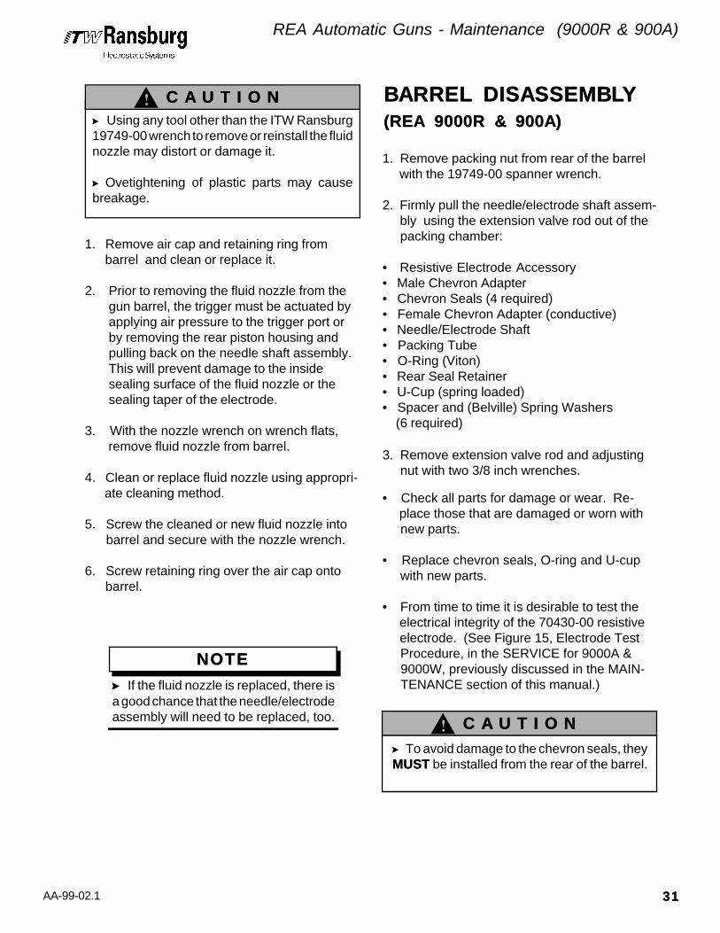
1. Remove air cap and retaining ring from barrel and clean or replace it.
2. Prior to removing the fluid nozzle from thegun barrel, the trigger must be actuated byapplying air pressure to the trigger port orby removing the rear piston housing andpulling back on the needle shaft assembly.This will prevent damage to the insidesealing surface of the fluid nozzle or thesealing taper of the electrode.
3. With the nozzle wrench on wrench flats, remove fluid nozzle from barrel.
4. Clean or replace fluid nozzle using appropri- ate cleaning method.
5. Screw the cleaned or new fluid nozzle into barrel and secure with the nozzle wrench.
6. Screw retaining ring over the air cap onto barrel.
NOTENOTE
>> If the fluid nozzle is replaced, there isa good chance that the needle/electrodeassembly will need to be replaced, too.
> Using any tool other than the ITW Ransburg19749-00 wrench to remove or reinstall the fluidnozzle may distort or damage it.
> Ovetightening of plastic parts may causebreakage.
C A U T I O NC A U T I O N!
C A U T I O NC A U T I O N!
1. Remove packing nut from rear of the barrel with the 19749-00 spanner wrench.
2. Firmly pull the needle/electrode shaft assem- bly using the extension valve rod out of the packing chamber:
• Resistive Electrode Accessory• Male Chevron Adapter• Chevron Seals (4 required)• Female Chevron Adapter (conductive)• Needle/Electrode Shaft• Packing Tube• O-Ring (Viton)• Rear Seal Retainer• U-Cup (spring loaded)• Spacer and (Belville) Spring Washers (6 required)
3. Remove extension valve rod and adjusting nut with two 3/8 inch wrenches.
• Check all parts for damage or wear. Re- place those that are damaged or worn with new parts.
• Replace chevron seals, O-ring and U-cup with new parts.
• From time to time it is desirable to test the electrical integrity of the 70430-00 resistive electrode. (See Figure 15, Electrode Test Procedure, in the SERVICE for 9000A & 9000W, previously discussed in the MAIN- TENANCE section of this manual.)
> To avoid damage to the chevron seals, theyMUSTMUST be installed from the rear of the barrel.
BARRELBARREL DISASSEMBL DISASSEMBLYY(REA 9000R & 900A)(REA 9000R & 900A)

AA-99-02.1
Figure 17: Spring Washer AssemblyFigure 17: Spring Washer Assembly
C A U T I O NC A U T I O N!
C A U T I O NC A U T I O N!
NOTENOTE
NOTENOTE
C A U T I O NC A U T I O N!
NOTENOTE
1. Place conductive female chevron adaptor onto the front of shaft with the concave side toward the front.
2. Screw the four new chevron seals onto shaft, concave sides forward.
> DO NOTDO NOT push the chevron sealsstraight onto the shaft. The shaft threadsmay damage the chevron bore and causethe gun to leak fluid.
> Inspect needle/electrode shaft sealingsurface for wear. If it is rough or uneven,replace it.
3. Place male nonconductive chevron adaptor onto shaft with the convex end rearward.
4. Screw needle/electrode onto shaft hand tighten.
5. Place packing tube over the end of shaft.
6. Place the new U-cup into rear retainer with the open side out.
7. Place new O-ring onto rear retainer.
8. Place rear retainer over shaft with the open end toward the rear.
9. Place the spacer over shaft, flanged end first.
10. Place the six (Belville) spring washers onto shaft with the first, third, and fifth ones with the cupped side facing the electrode (front of shaft), and the second, fourth and sixth ones with the cupped side facing the rear of shaft. (See Figure 17 below, Spring Washer Assembly.)
> There MUSTMUST be six spring washer(alternately faced) or the gun will malfunction!
11. Place packing nut onto shaft.
12. Place adjustment nut onto shaft.
13. Insert fluid nozzle into front of barrel and secure it firmly with the 19749-00 Spanner (nozzle) Wrench.
BARRELBARREL REASSEMBL REASSEMBLYY(REA 9000R & 900A)(REA 9000R & 900A)
> Failure to pack the needle electrode/electrode shaft assembly and packing tubemay cause lower electrical output of the gun.
> Apply a light coating of dielectricgrease to the chevron seals. The pack-ing tube 18842-02 should be thoroughlypacked with LSCH0009-00 dielectricgrease leaving no air space or voidswhen assembling.
>> The chevron adaptors and chevronseals should seat together to form anunbroken seal.
> Seat the U-cup into the rear retainervery carefully with the eraser end of apencil or a wood or plastic dowel rod.
REA Automatic Guns - Maintenance (9000R & 900A)
3232

AA-99-02.1
REA Automatic Guns - Maintenance (9000R & 900A)
3333
> DO NOTDO NOT overtighten. Overtightening may result in stripped threads or cracked barrel.
14. Insert the assembled items through the rear packing chamber of the barrel/cascade assembly.
15. Screw packing nut into rear of barrel and secure it with the 19749-00 Spanner Wrench.
> The packing nut should be tight enough that the needle shaft moves in and out with firm resistance.
16. Place the extension valve rod onto shaft and align the nuts.
17. To adjust 3/8" hex nut and extension valve rod: a. Push shaft fully forward until
needle/electrode seats in the fluidnozzle.
b. Screw nut clockwise until it runs outof threasd on end of needle shaft.
c. Screw the valve extension rod untilthe faces of the nuts are seatedagainst each other.
P-EXTENSION REMOVP-EXTENSION REMOVALAL(REA 9000R)(REA 9000R)1. Remove transformer connecting screw and remove plug from transformer.
2. Remove (2) P-extension screws from bottom mounting plate. Pull P-extension away.
3. Remove (2) nylon screws from body.
4. Gently pull P-extension from body locating the (2) spacers.
P-EXTENSION REPLACEMENTP-EXTENSION REPLACEMENT(REA 9000R)(REA 9000R)1. Locate (2) spacers in the counter bores of the body.
2. Locate the (2) spacers in counter bores of the P-extension.
3. Secure the (2) nylon screws in the body.
4. Locate the P-extension into the bottom plate and fasten using (2) screws.
5. Reinstall P-extension plug in transformer using screw.
AIR BUSHING /AIR BUSHING /BODYBODY DISASSEMBL DISASSEMBLYY(REA 9000R & 900A)(REA 9000R & 900A)
> The piston housing is spring-loaded. Use care in disassembly.
1. Remove piston housing from body.
2. Remove adjustment hex nut and air valve adjustment nut from extension rod.
3. Remove retaining ring from body and pull the barrel STRAIGHTSTRAIGHT out.
> Pull barrel STRAIGHT STRAIGHT out from body or bending of extension valve rod may occur.
4. Using pliers, grab the piston nut and pull the piston O-ring, shaft valve piston, piston washer, packing cup, piston and hex nut STRAIGHTSTRAIGHT out of the body.
5. Using the 20049-00 special wrench, re- move the bushing nut.
6. Remove the extension rod from the needle shaft or use an extra extension rod. Insert the hex end of the extension rod into a slot of the bushing and pull straight out.
C A U T I O NC A U T I O N!
C A U T I O NC A U T I O N!
NOTENOTE
C A U T I O NC A U T I O N!

AA-99-02.1
Figure 18: View of Rear BodyFigure 18: View of Rear Body
Figure 19: Rod and Trigger Adjustment NutsFigure 19: Rod and Trigger Adjustment Nuts(Do not exceed the 11/16 maximum dimension
shown in this figure)
7. Using a 3/8" nut driver, remove the valve seal retaining nut and O-ring.
AIR BUSHING /AIR BUSHING /BODYBODY ASSEMBL ASSEMBLYY(REA 9000R & 900A)(REA 9000R & 900A)1. Insert a new O-ring into the valve seal retaining nut.
2. Using a 3/8" nut driver, tighten the valve seal retaining nut into the body.
3. Insert a new O-ring into the groove on the front of the bushing.
4. Place a new o-ring onto the o-ring groove on the outside of the bushing.
5. Insert the bushing into the rear of the body and firmly press into position.
> > The bushing has a locator pin pres- sed into the front. This pin must align with the receptacle hole in the body. (See figure 18 below).
6. Insert the bushing nut into the rear of the body. Using the 20049-00 Spanner Wrench securely tighten the bushing nut into the body.
7. Pull the needle shaft back into an actuated position. Screw the trigger adjustment nut onto the needle shaft until there are no more threads.
8. Screw the extension rod on the needle shaft until the hex of the extension rod is flush against the hex of the trigger adjust- ment screw. (Using T-Shaped gauge on 19749-00, adjust to the 11/16 maximum dimension shown in Fig. 19 below.)
9. Using (2) 3/8" wrenches, tighten the (2) hexes against each other to prevent move- ment of the parts.
10. Lubricate the piston assembly with LSCH0009-00 dielectric grease.
11. Insert the piston assembly into the rear of the body, through the bushing nut.
12. Slide the gasket onto the barrel assembly.
13. Place the barrel assembly onto the front of the body. Making sure that the extension rod slides STRAIGHT through the body.
14. Tighten the retaining ring to the body using the 19749-00 Spanner Wrench.
NOTENOTE
REA Automatic Guns - Maintenance (9000R & 900A)
3434

AA-99-02.1
REA Automatic Guns - Maintenance (9000R & 900A)
3535
TRANSFORMER ASSEMBLTRANSFORMER ASSEMBLYYREPLACEMENTREPLACEMENT(REA 9000R & 900A)(REA 9000R & 900A)
> Turn OFFOFF all power, air and fluid at the source.
> The low voltage cable MUSTMUST be removed before removing the transformer assembly.
1. Remove the low voltage cable connector from the transformer by removing the screw and pull STRAIGHTSTRAIGHT out of the chamber.
2. Remove the barrel/cascade assembly. (See Barrel AssemblyRemoval for 9000R & 900A, previously discussed in this section.)
3. Remove the fiberglass screw.
4. Slide transformer backward and upward out of body channel.
> Generously lubricate transformer assembly base and body channel with LSCH0009-00 dielectric grease.
5. Slide replacement transformer into channel of automatic body.
6. Place gasket in position.
7. Replace the barrel/cascade assembly. (See Barrel Assembly Removal for 9000R & 900A, previously discussed in this section.)
8. Install low voltage cable connector by match- ing the hole on the connector and the trans- former, and pushing the connector straightstraight into the chamber.
9. Secure in place with screw.
17. Push the extension rod fully forward to seat the electrode into the fluid nozzle.
18. Screw onto the extension rod jam nut and the air valve adjusting nut.
19. Position the jam nut 1/16" from the end of the piston assembly.
20. Tighten the nuts against each other to prevent movement. (See Figure 20.)
21. If the extension rod rotates while you are tightening the nuts, hold it using an adjust- able wrench on the flats.
> The hex nut and air valve adjust nut control your air before fluid adjustment.
22. Install the two springs.
23. Install the rear piston housing.
Figure 20: Air Before Fluid AdaptorFigure 20: Air Before Fluid Adaptor(Piston Housing not shown for clarity)(Piston Housing not shown for clarity)
NOTENOTE
NOTENOTE
C A U T I O NC A U T I O N!
W A R N I N GW A R N I N G!

AA-99-02.1
LOW VOLLOW VOLTTAGE CABLEAGE CABLEREPLACEMENTREPLACEMENT(REA 9000R)(REA 9000R)1. Remove gun from robot.
2. Remove rear mounting plate from robot.
3. Using wrench on connector flats, disconnect low voltage cable from connector assembly.
4. Replace cable in robot arm.
5. Connect new cable to connector assembly using a wrench on the connector flats to tighten.
> > DO NOTDO NOT overtighten low voltage cable connection to spray gun, as damage to plastic parts may occur.
LOW VOLLOW VOLTTAGE CABLEAGE CABLECONNECTCONNECTOR ASSEMBLOR ASSEMBLYY(REA 9000R)(REA 9000R)1. Remove gun from robot.
2. Remove rear mounting plate from fobot.
3. Using a wrench on connector flats, discon- nect low voltage cable from connector assembly.
4. Remove screw from rear mounting plate.
5. Pull connector assembly out of mounting plate
6. Install new connector assembly in rear mounting plate and secure with screw.
7. Reconnect low voltage cable to connector assembly using a wrench on connector flats to tighten.
8. Reinstall mounting plate and gun to robot.
LOW VOLLOW VOLTTAGE CABLEAGE CABLEPLUG ASSEMBLPLUG ASSEMBLYY(REA 9000R)(REA 9000R)1. Remove gun from robot.
2. Thread screws into threaded hole in plug assembly.
3. Pull on screw to remove plug assembly from P-extension.
4. Insert female end of new plug assembly into P-extensions. Push plug assembly in until complete seated.
> It does not matter which receptacle of the plug assembly is connected to which pin of the P-extension.
5. Reinstall gun to robot.
NOTES:NOTES:
C A U T I O NC A U T I O N!NOTENOTE
REA Automatic Guns - Maintenance (9000R & 900A)
3636
AA-99-02.1
REA Automatic Guns - Maintenance (9000R & 900A)
3737
NOTES:NOTES:

AA-99-02.1
PARTS IDENTIFICATIONPARTS IDENTIFICATION
Please have this manual in hand for ready reference when ordering parts. We recommend that thepersonnel who are familiar with the product be authorized to contact us when ordering.
To insure prompt receipt of the correct parts, provide the following information with your partsorders:
• The model and serial numbers of the product.• Item description and part number. Both a prefix number (for item) and a suffix or dash number (for size or type) are required.• Cable and hose lengths as well as part numbers.
To order parts, contact your authorized ITW Ransburg electrostatic representative or call 1-800/726-8097. This number is for parts orders ONLY.
ORDERING PROCEDUREORDERING PROCEDURE
REA Automatic Guns - Parts Identification (9000A)
3838

AA-99-02.1
Figure 21: REA 9000A Solventborne AssemblyFigure 21: REA 9000A Solventborne Assembly
REA Automatic Guns - Parts Identification (9000A)
3939
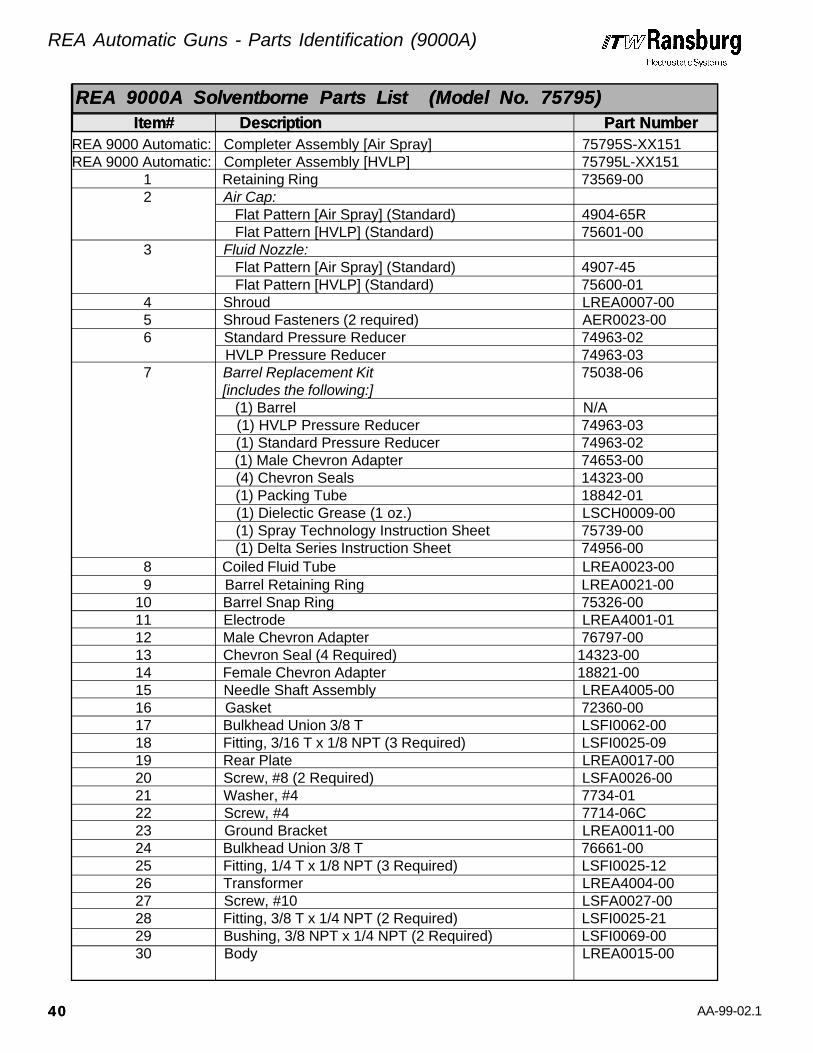
AA-99-02.1
REA 9000 Automatic: Completer Assembly [Air Spray] 75795S-XX151REA 9000 Automatic: Completer Assembly [HVLP] 75795L-XX151
1 Retaining Ring 73569-00 2 Air Cap: Flat Pattern [Air Spray] (Standard) 4904-65R
Flat Pattern [HVLP] (Standard) 75601-00 3 Fluid Nozzle:
Flat Pattern [Air Spray] (Standard) 4907-45 Flat Pattern [HVLP] (Standard) 75600-01
4 Shroud LREA0007-00 5 Shroud Fasteners (2 required) AER0023-00 6 Standard Pressure Reducer 74963-02
HVLP Pressure Reducer 74963-03 7 Barrel Replacement Kit 75038-06
[includes the following:] (1) Barrel N/A (1) HVLP Pressure Reducer 74963-03 (1) Standard Pressure Reducer 74963-02 (1) Male Chevron Adapter 74653-00 (4) Chevron Seals 14323-00 (1) Packing Tube 18842-01 (1) Dielectic Grease (1 oz.) LSCH0009-00 (1) Spray Technology Instruction Sheet 75739-00 (1) Delta Series Instruction Sheet 74956-00
8 Coiled Fluid Tube LREA0023-00 9 Barrel Retaining Ring LREA0021-00
10 Barrel Snap Ring 75326-00 11 Electrode LREA4001-01 12 Male Chevron Adapter 76797-00 13 Chevron Seal (4 Required) 14323-00 14 Female Chevron Adapter 18821-00 15 Needle Shaft Assembly LREA4005-00 16 Gasket 72360-00 17 Bulkhead Union 3/8 T LSFI0062-00 18 Fitting, 3/16 T x 1/8 NPT (3 Required) LSFI0025-09 19 Rear Plate LREA0017-00 20 Screw, #8 (2 Required) LSFA0026-00 21 Washer, #4 7734-01 22 Screw, #4 7714-06C 23 Ground Bracket LREA0011-00
24 Bulkhead Union 3/8 T 76661-00 25 Fitting, 1/4 T x 1/8 NPT (3 Required) LSFI0025-12 26 Transformer LREA4004-00 27 Screw, #10 LSFA0027-00 28 Fitting, 3/8 T x 1/4 NPT (2 Required) LSFI0025-21 29 Bushing, 3/8 NPT x 1/4 NPT (2 Required) LSFI0069-00 30 Body LREA0015-00
REA 9000A Solventborne Parts List (Model No. 75795)REA 9000A Solventborne Parts List (Model No. 75795) Item# Item# Description Description Part Number Part Number
REA Automatic Guns - Parts Identification (9000A)
4040

AA-99-02.1
31 Bracket, Mount LREA0019-00 32 Screw, 5/16 (2 Required) LSFA0028-02 33 Bracket LREA0018-00 34 Screw, 5/16 (5 Required) LSFA0028-01 35 O-Ring, .551 I.D. x .070 C.S., Solvent Resistent 7554-12 36 Plug Assembly [includes item 35] 74191-01 37 Screw, M5 73490-01
38 L.V. Cable Assembly: Cable (36 ft.) 78084-36 Cable (50 ft.) 78084-50 Cable (75 ft.) 78084-75 Cable (100 ft.) 78084-100
39 Ferrule 18844-00 40 Nut 18843-00 41 O-Ring, .364 I.D. x .070 C.S., Solvent Proof SSG-8137 42 Manifold 76929-00 43 Fitting, 3/8 T x 1/4 AN LSFI0022-04 44 Fitting, 1/4 T x 1/4 AN LSFI0022-06 45 Valve Assembly [includes items 46-56:] 76917-00 46 Valve Needle 76921-00 47 Needle Seat 75960-00 48 O-Ring, .426 I.D. x .070 C.S., Solvent Proof SSG-8136 49 Valve Body 76918-00 50 Needle Seal 76920-00 51 Spring Washer 76927-00 52 Valve Spring 76928-00 53 Piston Nut 76919-00 54 Piston Cup VA-246 55 Clamping Nut 76926-00 56 Valve Cap 76925-00 57 Fitting, 3/16 T x 1/8 NPT (2 Required) 14157-08
Manifold Assembly (Trigger and Dump) 76923-00 Manifold Assembly (Trigger Only) 76930-01
Dielectric Grease (1 oz.) LSCH0009-00 Dielectric Grease (4 oz.) 59972-00
Special Multi-Purpose Wrench 19749-00 Spanner Wrench 20049-00
REA 9000A Solventborne Parts List (Model No. 75795)REA 9000A Solventborne Parts List (Model No. 75795) Item# Item# Description Description Part Number Part Number
REA Automatic Guns - Parts Identification (9000A)
4141

AA-99-02.1
Rebuild Kit for Trigger and Dump Valves 76931-00 [Kit includes:] (1) Piston Cup VA-246 (1) Needle Seal 76920-00 (1) O-Ring, .426 I.D. x .070 C.S., Solvent Resistent 7554-10 (1) Valve Spring 76928-00 (1) Needle Seat 75960-00 (1) Valve Spring 76928-00 (1) Needle 76921-00 (1) Instruction Sheet 76924-00 (1) O-Ring, .426 I.D. x .070 C.S., Solvent Proof SSG-8136
Metric Fitting Conversion Kit 76140-00 [includes the following items:] (1) Fitting, 1/8 NPT X 6 mm T 76137-06 (2) Fitting, 1/4 NPT X 6 mm T 76137-07 (2) Fitting, 3/8 NPT X 12 mm T 76137-21 (1) Fitting, 1/8 NPT X 1/8 T LSFI0025-05 (1) Fitting, 1/4 NPT X 3/8 T LSFI0025-21
Rebuild Kit(trigger & dump only) 76931-00 1 2 3 4Electrode LREA4001-01 2 2 4 4Needle Shaft LREA4005-00 1 1 2 2Cartridge Valve Assembly 76917-00 1 1 2 2Transformer LREA4004-00 1 1 1 1Barrel Kit 75038-06 1 1 2 2Cable Assembly 76876-36 1 1 2 2 Cable (36 ft.)
76876-50 1 1 2 2 Cable (50 ft.) 76876-75 1 1 2 2 Cable (75 ft.)
76876-100 1 1 2 2 Cable (100 ft.)Nylon Screw 73490-01 1 2 2 3Wrench 19749-00 2 2 4 4Fluid Nozzle 4907-XX 2 2 4 4 Replace XX with 44, 45, 46, 47 or 48Air cap 4904-XX 2 2 4 4 Replace XX with 63, 98, or 65R.Retaining Ring 73569-00 1 1 2 2Disposable Gun Covers 76116-00-K5 1 2 3 4Low Voltage Tester LTST5000 1 1 1 1 For troubleshooting control unit
& cable.High Voltage Test Probe Kit 76652-01 1 1 1 1 For troubleshooting complete
Assembly.
REA 9000A Spare Parts in Kit Form REA 9000A Spare Parts in Kit Form (Model No. 75795)(Model No. 75795)
REA 9000A Recommended Spare Parts REA 9000A Recommended Spare Parts (Model No. 75795)(Model No. 75795)
Description Description Part Number No. of Guns Part Number No. of Guns Notes Notes 1-2 3-4 5-6 7-8 1-2 3-4 5-6 7-8
Item# Item# Description Description Part Number Part Number
REA Automatic Guns - Parts Identification (9000A)
4242

AA-99-02.1
Figure 22: REA 9000R Solventborne AssemblyFigure 22: REA 9000R Solventborne Assembly
REA Automatic Guns - Parts Identification (9000R)
4343

AA-99-02.1
Figure 23: REA 9000R Rear Mounting Plate AssemblyFigure 23: REA 9000R Rear Mounting Plate Assembly
REA Automatic Guns - Parts Identification (9000R)
4444
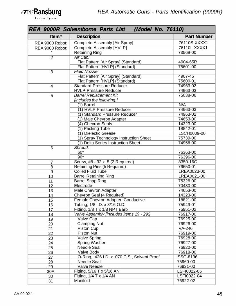
AA-99-02.1
Complete Assembly [Air Spray]Complete Assembly [HVLP]Retaining RingAir Cap: Flat Pattern [Air Spray] (Standard) Flat Pattern [HVLP] (Standard)Fluid Nozzle: Flat Pattern [Air Spray] (Standard) Flat Pattern [HVLP] (Standard)Standard Pressure ReducerHVLP Pressure ReducerBarrel Replacement Kit[includes the following:] (1) Barrel (1) HVLP Pressure Reducer (1) Standard Pressure Reducer (1) Male Chevron Adapter (4) Chevron Seals (1) Packing Tube (1) Dielectic Grease (1) Spray Technology Instruction Sheet (1) Delta Series Instruction SheetShroud: 60o
90o
Screw, #8 - 32 x .5 (2 Required)Retaining Pins (5 Required)Coiled Fluid TubeBarrel Retaining RingBarrel Snap RingElectrodeMale Chevron AdapterChevron Seal (4 Required)Female Chevron Adapter, ConductiveTubing, 1/8 I.D. x 3/16 O.D.Fitting, 1/8 T x 1/8 NPT BarbValve Assembly [includes items 19 - 29:] Valve Cap Clamping Nut Piston Cup Piston Nut Valve Spring Spring Washer Needle Seal Valve Body O-Ring, .426 I.D. x .070 C.S., Solvent Proof Needle Seat Valve NeedleFitting, 5/16 T x 5/16 ANFitting, 1/4 T x 1/4 ANManifold
76110S-XXXX1 76110L-XXXX1 73569-00
4904-65R 75601-00
4907-45 75600-01 74963-02 74963-03 75038-06
N/A 74963-03 74963-02 74653-00 14323-00 18842-01 LSCH0009-00 75739-00 74956-00
76363-00 76396-00 8350-16C 76650-01 LREA0023-00 LREA0021-00 75326-00 70430-00 74653-00 14323-00 18821-00 75949-01 75951-02 76917-00 76925-00 76926-00 VA-246 76919-00 76928-00 76927-00 76920-00 76918-00 SSG-8136 75960-00 76921-00 LSFI0022-05 LSFI0022-04 76922-02
1 2
3
4
5
6
7 8 91011121314151617181920212223242526272829
30A3031
REA 9000 Robot:REA 9000 Robot:
REA 9000R Solventborne Parts List (Model No. 76110)REA 9000R Solventborne Parts List (Model No. 76110) Item# Item# Description Description Part Number Part Number
REA Automatic Guns - Parts Identification (9000R)
4545

AA-99-02.1
32 O-Ring, .364 I.D. x .070 C.S., Solvent Proof SSG-8137 33 Ferrule 18844-00 34 Nut 18843-00 35 Needle Shaft Assembly 18865-04 36 Packing Tube 18842-01 37 Rear Retainer 18836-00 38 O-Ring, .301 I.D. x .070 C.S., Solvent Resistent 7554-08 39 U-Cup Seal 10051-05 40 Spacer 18837-00 41 Spring Washer ( 6 Required) 17390-04 42 Packing Nut 18838-00 43 Gasket 72360-00 44 Nut 18859-00 45 Valve Rod Extension 76215-00 46 Fitting, 3/8 T x 1/4 NPT LSFI0025-21 47 Tubing, 3/8 O.D. H-2338 48 Tubing, 3/16 O.D. SSP-5014 49 Fitting, 3/16 T x 1/8 NPT LSFI0025-09 50 Body 76231-00 51 Screw, 5/16-18 x 1.50 LG (2 Required) 76198-48C 52 Retaining Nut 20053-00 53 O-Ring, .239 I.D. x .070 C.S., Solvent Proof 13076-10 54 Elbow, 3/8 T x 1/4 NPT 14157-03 55 Screw, #10 LSFA0027-00 56 Transformer LREA4004-00 57 O-Ring, .551 I.D. x .070 C.S., Solvent Resistent 7554-12 58 Screw, M5 73490-01 59 O-Ring, .426 I.D. x .070 C.S., Solvent Proof 13076-13 60 O-Ring, .614 I.D. x .070 C.S., Solvent Resistent 7554-42 61 Bushing 76216-00 62 O-Ring, .801 I.D. x .070 C.S., Solvent Resistent 7554-33 63 Bushing Retainer 76200-00 64 O-Ring, .487 I.D. x .103 C.S., Solvent Resistent 7554-28 65 O-Ring, .299 I.D. x .103 C.S., Solvent Resistent 7554-111 66 Piston Shaft 76220-00 67 Piston Washer 20057-00 68 Piston Cup 7723-06 69 Piston 20056-00 70 Nut 7733-44 71 Spring 9334-00 72 Nut 7733-07 73 Air Valve Adjustment Nut 76199-00 74 Spring 17615-00 75 Piston Housing 76217-00 76 Spacer (2 Required) 76219-00 77 P Extension:
60o 76232-0190o 76232-02
REA 9000R Solventborne Parts List (Model No. 76110)REA 9000R Solventborne Parts List (Model No. 76110) Item# Item# Description Description Part Number Part Number
REA Automatic Guns - Parts Identification (9000R)
4646

AA-99-02.1
78 Retaining Ring 76224-00 79 Fitting, 3/16 T x 1/8 NPT LSFI0025-09 80 Fitting, 1/8 T x 1/8 NPT (2 Required) 75951-02 81 Rear Plate 76229-00 82 Screw, 5/16 LSFA0028-01 83 O-Ring, .208 I.D. x .070 C.S., Solvent Proof (3 Req’d) SSG-8163 84 O-Ring, .426 I.D x .070 C.S., Solvent Proof (2 Req’d) SSG-8134 85 O-Ring, .301 I.D. x .070 C.S., Solvent Proof (2 Req’d) SSG-8134
86 Fitting (2 Required) (1) EMF-201 [All Parts are Required to Make a Complete Fitting] (1) EMF-202
(1) EMF-203 (1) 76223-00 (1) SSG-8162
87 Fitting, 3/8 T x 1/4 NPT (2 Required) LSFI0025-21 Rear Mounting Plate Assembly
[Includes items 89-100:] 36’ of Cable & Hoses, Polyethylene Tube 76222-36 50’ of Cable & Hoses, Polyethylene Tube 76222-50 75’ of Cable & Hoses, Polyethylene Tube 76222-75 00’ of Cable & Hoses, Polyethylene Tube 76222-100 36’ of Cable & Hoses, Teflon Tube 76222-36A 50’ of Cable & Hoses, Teflon Tube 76222-50A 75’ of Cable & Hoses, Teflon Tube 76222-75A 100’ of Cable & Hoses, Teflon Tube 76222-100A
88 DR1 Regulator 76607-02 89 Rear Plate 76197-00
90 Barbed Fitting (3 Required) EMF-82-1 91 Fitting, 1/4 T x 1/4 AN LSFI0033-03
92 Fitting 3/8 T x 1/4 NPT (2 Required) 77947-00 93 Tubing, 3/16 O.D. SSP-5014 94 Fitting, 5/16 T x 5/16 AN LSFI0033-02 95 Tubing, 1/4 O.D. SSP-5012 96 Tubing, 5/16 O.D. SSP-5011 97 O-Ring, .551 I.D. x .070 C.S., Solvent Resistent 7554-12 98 Plug connector (includes Items 97 & 99) 76873-01 98A LV Plug Extension Assembly 76871-00 99 Screw, M5 73490-01 100 L. V. Cable Assembly: Cable (36 ft.) 78084-36 Cable (50 ft.) 78084-50 Cable (75 ft.) 78084-75 Cable (100 ft.) 78084-100 O-Ring Kit for Rear Plate 76527-00
Dielectric Grease (1 oz.) LSCH0009-00 Dielectric Grease (4 oz.) 59972-00
Special Multi-Purpose Wrench 19749-00 Spanner Wrench 20049-00
REA 9000R Solventborne Parts List (Model No. 76110)REA 9000R Solventborne Parts List (Model No. 76110) Item# Item# Description Description Part Number Part Number
4747
REA Automatic Guns - Parts Identification (9000R)

AA-99-02.1
Rebuild Kits: For Dump Valve Only [76917-00] 76931-00
[Includes the following:] (1) Needle Seat 75960-00 (1) Valve Needle 76921-00 (1) O-Ring, .426 I.D. x .070 C.S., Solvent Resistent 7554-10 (1) Needle Seal 76920-00 (1) Valve Spring 76928-00 (1) Piston Seal VA-246
Soft Parts for the Gun 76526-00 [includes the following:]
(1) Male Chevron Adapter 74653-00 (4) Chevron Seal 14323-00 (1) Female Chevron Adapter 18821-00 (1) O-Ring, .301 I.D. x .070 C.S., Solvent Resistent 7554-08 (1) U-Cup 10051-05 (1) O-Ring, .364 I.D. x .070 C.S., Solvent Resistent 7554-09 (1) Gasket, Barrel 72360-00 (1) O-Ring, .239 I.D. x .070 C.S., Solvent Proof 13076-10 (1) O-Ring, .426 I.D. x .070 C.S., Solvent Proof 13076-13 (1) O-Ring, .614 I.D. x .070 C.S., Solvent Resistent 7554-42 (1) O-Ring, .299 I.D. x .103 C.S., Solvent Resistent 7554-111 (1) Packing, Cup 7723-06 (1) Dielectic Grease (1 oz.) LSCH0009-00 (1) O-Ring, .801 I.D. x .070, Solvent Resistent 7554-33
For DR1Regulator 73913-00 [includes the following:] (1) Diaphragm 74157-03 (1) Diaphragm 74157-04 (1) Diaphragm 74273-00 (3) O-Ring, .489 I.D. x .070 C.S., Solvent Resistent 7554-11 For DR1 Requlator 74160-00 [Needle and Seat]
Needle Shaft Assembly 75732-01 [Completely Assembled Needle Shaft, less grease] (1) Electrode 70130-00 (1) Needle Shaft 18865-04 (1) Male Chevron Adapter 74653-00 (4) Chevron Seals 14323-00 (1) Female Chevron Adapter 18821-00 (1) Packing Tube 18842-00 (1) Retainer 18836-00 (1) O-Ring, .301 I.D. x .070 C.S., Solvent Resistent 7554-08 (1) Spacer 18837-00 (1) Packing Nut 18838-00 (2) Nut 18859-00 (1) U-Cup Seal 10051-05 (6) Belville Washer 17390-04
Item# Item# Description Description Part Number Part NumberREA 9000R Spare Parts in Kit form REA 9000R Spare Parts in Kit form (Model No. 76110)(Model No. 76110)
4848
REA Automatic Guns - Parts Identification (9000R)
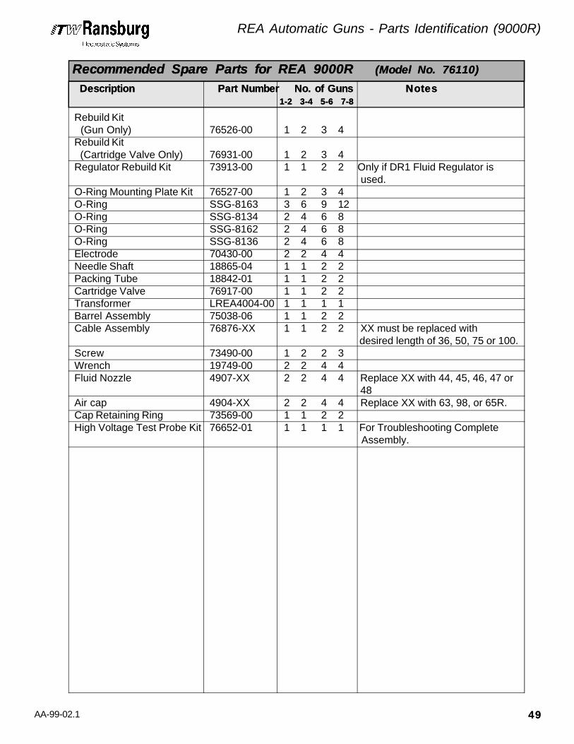
AA-99-02.1
Rebuild Kit (Gun Only) 76526-00 1 2 3 4Rebuild Kit (Cartridge Valve Only) 76931-00 1 2 3 4Regulator Rebuild Kit 73913-00 1 1 2 2 Only if DR1 Fluid Regulator is
used.O-Ring Mounting Plate Kit 76527-00 1 2 3 4O-Ring SSG-8163 3 6 9 12O-Ring SSG-8134 2 4 6 8O-Ring SSG-8162 2 4 6 8O-Ring SSG-8136 2 4 6 8Electrode 70430-00 2 2 4 4Needle Shaft 18865-04 1 1 2 2Packing Tube 18842-01 1 1 2 2Cartridge Valve 76917-00 1 1 2 2Transformer LREA4004-00 1 1 1 1Barrel Assembly 75038-06 1 1 2 2Cable Assembly 76876-XX 1 1 2 2 XX must be replaced with
desired length of 36, 50, 75 or 100.Screw 73490-00 1 2 2 3Wrench 19749-00 2 2 4 4Fluid Nozzle 4907-XX 2 2 4 4 Replace XX with 44, 45, 46, 47 or
48Air cap 4904-XX 2 2 4 4 Replace XX with 63, 98, or 65R.Cap Retaining Ring 73569-00 1 1 2 2High Voltage Test Probe Kit 76652-01 1 1 1 1 For Troubleshooting Complete
Assembly.
Description Description Part Number No. of Guns Part Number No. of Guns NotesNotes 1-2 3-4 5-6 7-81-2 3-4 5-6 7-8
Recommended Spare Parts for REA 9000R Recommended Spare Parts for REA 9000R (Model No. 76110) (Model No. 76110)
REA Automatic Guns - Parts Identification (9000R)
4949
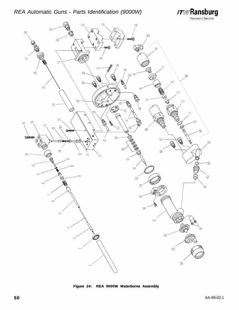
AA-99-02.1
Figure 24: REA 9000W Waterborne AssemblyFigure 24: REA 9000W Waterborne Assembly
5050
REA Automatic Guns - Parts Identification (9000W)

AA-99-02.1
REA 9000W Complete Assembly 77140-01High Voltage Probe Assembly 77156-03[includes items 1-13:]
1 High Voltage Probe Body 77157-03 2 Air Knife 77172-00 3 Electrode LREA4001-01 4 High Voltage Probe Needle Shaft 77167-03 5 Tubing, 1/4 O.D. x 3/16 I.D., 4.25”, Poly 9704-02 6 Coupling 77175-00 7 Compression Spring 75840-00 8 Contact Plug A10123-00 9 Retaining Plug 75836-01 10 Compression Spring 75831-03 11 Retaining Ring, External 75832-05 12 Contact Pin 75833-02 13 Retaining Cap 75835-00 14 Retaining Nut 75847-01 15 Screw, 1/4-20 x 2 (4 Required) 9141-64C
High Voltage Probe Holder Assembly 77177-00[includes items 16-21:]
16 Probe Holder Body 77158-00 17 Contact Rod 75830-02 18 Compression Spring 75831-03 19 Retaining Ring 75832-05 20 Contact Plunger 77163-00 20A Retaining Cap 75884-00 21 O-Ring, .551 I.D. x .070 C.S., Solvent Resistent LSOR0007-05
High Voltage Module Assembly 77301-01[includes items 22, 24-28]
22 Module Shell 77155-01 23 Screw, #10-32 x 2.0 77302-65F 24 Cable Adapter 77168-01 25 Contact Assembly 77173-00 26 Nut 77170-01 27 Connector Body 18687-00 28 Tube Fitting Nut, 3/8 T 3587-03 29 Fitting, 3/8 T x 1/4 NPT (2 Required) LSFI0025-21 30 Bushing, 3/8 NPT x 1/4 NPT (2 Required) LSFI0069-00 31 Gun Body LREA0015-00 32 Mounting Bracket, Upper LREA0019-00 33 Mounting Bracket, Lower LREA0018-00 34 Screw, 5/16 - 18 x 1.50 (5 Required) LSFA0028-01 35 Screw, 5/16 - 18 x 1 (2 Required) LSFA0028-02 36 Fitting, 1/4 T x 1/4 AN LSFI0022-04 37 Screw, 1/4-20 x 1.5 (2 Required) LSFA0004-48C 38 Fitting, 1/4 T x 1/8 AN (4 Required) LSFI0025-12 39 Fitting, 3/8 T x 1/4 AN (2 Required) LSFI0022-06
REA 9000W Waterborne Parts List REA 9000W Waterborne Parts List (Model No. 77140)(Model No. 77140)
Item# Item# Description Description Part Number Part Number
REA Automatic Guns - Parts Identification (9000W)
5151
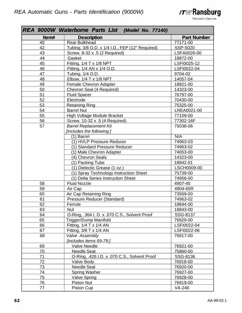
AA-99-02.1
40 Rear Bulkhead 77171-00 42 Tubing, 3/8 O.D. x 1/4 I.D., FEP (12" Required) SSP-5020 43 Screw, 8-32 x .5 (2 Required) LSFA0026-00 44 Gasket 18872-00 45 Fitting, 1/4 T x 1/8 NPT LSFI0025-12 46 Fitting, 1/4 AN x 1/4 O.D. LSFI0022-04 47 Tubing, 1/4 O.D. 9704-02 48 Elbow, 1/4 T x 1/8 NPT 14057-04 49 Female Chevron Adapter 18821-00 50 Chevron Seal (4 Required) 14323-00 51 Fluid Spacer 76797-00 52 Electrode 70430-00 53 Retaining Ring 75325-00 54 Barrel Nut LREA0021-00 55 High Voltage Module Bracket 77159-00 56 Screw, 10-32 x .5 (4 Required) 77302-16F 57 Barrel Replacement Kit 75038-06
[includes the following:] (1) Barrel N/A
(1) HVLP Pressure Reducer 74963-03 (1) Standard Pressure Reducer 74963-02 (1) Male Chevron Adapter 74653-00
(4) Chevron Seals 14323-00 (1) Packing Tube 18842-01
(1) Dielectic Grease (1 oz.) LSCH0009-00 (1) Spray Technology Instruction Sheet 75739-00 (1) Delta Series Instruction Sheet 74956-00
58 Fluid Nozzle 4907-45 59 Air Cap 4904-65R 60 Air Cap Retaining Ring 73569-00 61 Pressure Reducer (Standard) 74963-02 62 Ferrule 18844-00 63 Nut 18843-00 64 O-Ring, .364 I. D. x .070 C.S., Solvent Proof SSG-8137 65 Trigger/Dump Manifold 76929-00 66 Fitting, 1/4 T x 1/4 AN LSFI0022-04 67 Fitting, 3/8 T x 1/4 AN LSFI0022-06 68 Valve Assembly 76917-00 [includes items 69-79:] 69 Valve Needle 76921-00 70 Needle Seat 75960-00 71 O-Ring, .426 I.D. x .070 C.S., Solvent Proof SSG-8136 72 Valve Body 76918-00 73 Needle Seal 76920-00 74 Spring Washer 76927-00 75 Valve Spring 76928-00 76 Piston Nut 76919-00 77 Piston Cup VA-246
REA 9000W Waterborne Parts List REA 9000W Waterborne Parts List (Model No. 77140)(Model No. 77140)
Item# Item# Description Description Part Number Part Number
REA Automatic Guns - Parts Identification (9000W)
5252
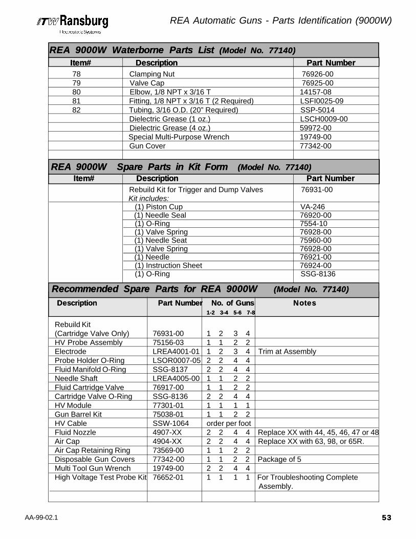
AA-99-02.1
78 Clamping Nut 76926-00 79 Valve Cap 76925-00 80 Elbow, 1/8 NPT x 3/16 T 14157-08 81 Fitting, 1/8 NPT x 3/16 T (2 Required) LSFI0025-09 82 Tubing, 3/16 O.D. (20” Required) SSP-5014
Dielectric Grease (1 oz.) LSCH0009-00 Dielectric Grease (4 oz.) 59972-00
Special Multi-Purpose Wrench 19749-00 Gun Cover 77342-00
Rebuild Kit(Cartridge Valve Only) 76931-00 1 2 3 4HV Probe Assembly 75156-03 1 1 2 2Electrode LREA4001-01 1 2 3 4 Trim at AssemblyProbe Holder O-Ring LSOR0007-05 2 2 4 4Fluid Manifold O-Ring SSG-8137 2 2 4 4Needle Shaft LREA4005-00 1 1 2 2Fluid Cartridge Valve 76917-00 1 1 2 2Cartridge Valve O-Ring SSG-8136 2 2 4 4HV Module 77301-01 1 1 1 1Gun Barrel Kit 75038-01 1 1 2 2HV Cable SSW-1064 order per footFluid Nozzle 4907-XX 2 2 4 4 Replace XX with 44, 45, 46, 47 or 48Air Cap 4904-XX 2 2 4 4 Replace XX with 63, 98, or 65R.Air Cap Retaining Ring 73569-00 1 1 2 2Disposable Gun Covers 77342-00 1 1 2 2 Package of 5Multi Tool Gun Wrench 19749-00 2 2 4 4High Voltage Test Probe Kit 76652-01 1 1 1 1 For Troubleshooting Complete
Assembly.
Rebuild Kit for Trigger and Dump Valves 76931-00 Kit includes: (1) Piston Cup VA-246 (1) Needle Seal 76920-00 (1) O-Ring 7554-10 (1) Valve Spring 76928-00 (1) Needle Seat 75960-00 (1) Valve Spring 76928-00 (1) Needle 76921-00 (1) Instruction Sheet 76924-00 (1) O-Ring SSG-8136
Recommended Spare Parts for REA 9000W Recommended Spare Parts for REA 9000W (Model No. 77140)(Model No. 77140)
Description Description Part Number No. of Guns Part Number No. of Guns NotesNotes 1-2 3-4 5-6 7-8 1-2 3-4 5-6 7-8
Item# Item# Description Description Part Number Part Number
REA 9000W Spare Parts in Kit Form REA 9000W Spare Parts in Kit Form (Model No. 77140)(Model No. 77140)
REA 9000W Waterborne Parts List REA 9000W Waterborne Parts List (Model No. 77140)(Model No. 77140)
Item# Item# Description Description Part Number Part Number
REA Automatic Guns - Parts Identification (9000W)
5353

AA-99-02.1
Figure 26: REA 900A Solventborne AssemblyFigure 26: REA 900A Solventborne Assembly
REA Automatic Guns - Parts Identification (900A)
5454

AA-99-02.1
REA 900A Automatic [Air Spray]:Assembly, Complete without Dump Valve 77359S-BB111Assembly, Complete with Acetron Dump Valve 77359S-BB221Assembly, Complete with Techtron Dump Valve 77359S-BB331
REA 900A Automatic [HVLP]:Assembly, Complete without Dump Valve 77359L-BB111Assembly, Complete with Acetron Dump Valve 77359L-BB221Assembly, Complete with Techtron Dump Valve 77359L-BB3311
1 Air Nozzle Retaining Ring 76936-00 2 Air Cap:
Flat Pattern [Air Spray] (Standard) 4904-65R Flat Pattern [HVLP] (Standard) 75601-00
3 Fluid Nozzle: Flat Pattern [Air Spray] (Standard) 4907-45 Flat Pattern [HVLP] (Standard) 75600-01
4 Seal Nut 76935-00 5 O-Ring, 1.612 I.D. x .103 C.S., Solvent Resistent 7554-85 6 Shroud 77554-00 7 Coiled Fluid Tube (route on right side) LREA0023-00 8 Barrel Replacement Kit 75038-06
[includes the following:] (1) Barrel N/A
(1) HVLP Pressure Reducer 74963-03 (1) Standard Pressure Reducer 74963-02 (1) Male Chevron Adapter 74653-00 (4) Chevron Seals 14324-00 (1) Packing Tube 18842-01 (1) Dielectic Grease (1 oz.) LSCH0009-00
(1) Spray Technology Instruction Sheet 75739-00 (1) Delta Series Instruction Sheet 74956-00
9 Barrel Nut LREA0021-00 10 Retaining Ring 75326-00 11 Needle Electrode 70430-00 12 Male Chevron Adapter 74653-00 13 Chevron Seal (4 Required) 14323-00 14 Female Chevron Adapter 18821-00 15 Fitting, 1/4 T x 1/4 AN LSF1022-04 16 Adapter Fitting 77556-00 17 O-Ring, .364 I.D. x .070 C.S., Solvent Proof SSG-8137 18 Standard Pressure Reducer 74963-02
HVLP Pressure Reducer 74963-03 19 Needle Assembly 18865-04 20 Packing Tube 18842-01 21 Rear Needle Retainer 18836-00 22 O-Ring, .301 I.D. x .070 C.S., Solvent Resistent 7554-08
Item# Item# Description Description Part Number Part Number
REA 900A Solventborne Parts List REA 900A Solventborne Parts List (Model No. 77359)(Model No. 77359)
REA Automatic Guns - Parts Identification (900A)
5555

AA-99-02.1
23 Spring Loaded U-Cup Seal 10051-05 24 Seal & Spring Spacer 18837-00 25 Spring Washer (6 Required) 17390-04 26 Packing Nut 18838-00 27 Barrel Gasket 72360-00 28 Trigger Adjust Lock Nut 18859-00 29 Valve Rod Extension 76215-00 30 Valve Seal Retaining Nut 20053-00 31 O-Ring, .239 I.D. x .070 C.S., Solvent Proof 13076-10 32 Elbow, 1/4 NPT x 3/8 T (2 Required) 14157-03 33 Transformer Assembly LREA4004-01 34 Screw, #10-32 x 1.5 LSFA0027-00 35 O-Ring, .551 I.D. x .070 C.S., Solvent Resistent 7554-12 36 L.V. Cable Plug Assembly [includes item 35] 74191-01 37 Screw, M5 73490-01 38 L.V. Cable Assembly:
Cable (36 ft.) 78084-36 Cable (50 ft.) 78084-50 Cable (75 ft.) 78084-75 Cable (100 ft.) 78084-100
39 Gun Body Assembly 76231-00 40 Fitting, 3/16 T x 1/8 NPT LSF10025-09 41 Screw, 5/16-18 x 1.50 LG (2 Required) 76198-48C 42 O-Ring, .426 I.D. x .070 C.S., Solvent Proof 13076-13 43 O-Ring, .614 I.D. x .070 C.S., Solvent Resistent 7554-42 44 Bushing Assembly 76216-00 45 Bushing Retainer 76200-00 46 O-Ring, .487 I.D. x .103 C.S., Solvent Resistent 7554-28 47 O-Ring, .299 I.D. x .103 C.S.,Solvent Resistent 7554-111 48 Piston Shaft 76220-00 49 Piston Washer 20057-00 50 Teflon Packing Cup 7723-06 51 Piston 20056-00 52 Jam Nut 3/8-24 7733-44 53 Spring 9334-00 54 Hex Nut 10-32 7733-07 55 Air Valve Adjust Nut 76199-00 56 Spring 17615-00 57 Piston Housing 76217-00 58 Fitting, 1/8 NPT x 1/4 T LSFI0025-12 59 Valve Assembly 76917-00 [includes items 60-70:] 60 Valve Cap 76925-00 61 Clamping Nut 76926-00 62 Piston Cup VA-246 63 Piston Nut 76919-00 64 Valve Spring 76928-00
REA 900A Solventborne Parts List REA 900A Solventborne Parts List (Model No. 77359)(Model No. 77359)
Item# Item# Description Description Part Number Part Number
REA Automatic Guns - Parts Identification (900A)
5656

AA-99-02.1
65 Spring Washer 76927-00 66 Needle Seal 76920-00 67 Valve Body 76918-00 68 O-Ring, .426 I. D. x .070 C.S., Solvent Proof SSG-8136 69 Needle Seat 75960-00 70 Valve Needle 76921-00 71 SS Male Connector, 3/8 Tube x 1/4 NPT 41-FTC-1002 72 Tubing, 3/8 O.D. x 1/4 I.D. (6ft. Required), FEP SSP-5020 Label, Grounded Fluid Supply (2 Required) 77557-00 73 Fitting, 1/4 AN x 3/8 T LSFI0022-06 74 Screw for use with:
Assembly Without Dump Valve (2 Required) LSFA0004-40C Assembly With Dump Manifold (4 Required) LSFA0004-64C
75 Fitting, 1/4 AN x 3/8 T LSFI0022-06 76 Manifold Assembly Without Dump Valve 77550-01
Manifold Assembly with Acetron Dump Manifold 77550-02Manifold Assembly with Techtron Dump Manifold 77550-03
77 Rear Bulkhead Plate 77553-00 78 Fitting, 1/4 AN x 1/4 T LSFI0022-04 79 Screw, 3/8 - 16 x .75 LG LSFA0021-24C 80 Tubing, 3/8 O.D. x 1/4 I.D. (7.25” Required) H-2338 81 Tube Fitting, 1/4 NPT x 3/8 O.D. (2 Required) LSFI0025-21 82 Tubing, 3/16 O.D. x .025 Wall (10.5” Required) SSP-5014 83 Tube Fitting, 1/8 NPT x 3/16 O.D. LSF10025-09 84 Tube Fitting, 1/4 NPT x 1/2 O.D. (2 Required) LSFI0025-26 85 Tube Fitting, 1/8 NPT x 1/4 O.D. (2 Required) LSFI0025-12 86 Gun Bar Bracket (Upper) 77161-02 87 Screw, 5/16-18 x 1.50 LG (5 Required) LSFA0028-01 88 Gun Bar Bracket (Lower) LREA0018-00
Dielectric Grease (1 oz.) LSCH0009-00 Dielectric Grease (4 oz.) 59972-00
Special Multi-Purpose Wrench 19749-00 Spanner Wrench 20049-00 Nut Tool 77558-00
REA 900A Solventborne Parts List REA 900A Solventborne Parts List (Model No. 77359)(Model No. 77359)
Item# Item# Description Description Part Number Part Number
REA Automatic Guns - Parts Identification (900A)
5757

AA-99-02.1
Rebuild Kit for Trigger and Dump Valves 76931-00 [includes the following:] (1) Piston Cup VA-246 (1) Needle Seal 76920-00 (1) O-Ring 7554-10 (1) Needle Seat 75960-00 (1) Valve Spring 76928-00 (1) Needle 76921-00 (1) Instruction Sheet 76924-00 (1) O-Ring SSG-8136
Soft Parts for the Gun 76526-00 [includes the following:]
(1) Male Chevron Adapter 74653-00(4) Chevron Seal 14323-00(1) Female Chevron Adapter 18821-00(1) O-Ring 7554-08(1) U-Cup 10051-05(1) O-Ring 7554-09(1) Gasket, Barrel 72360-00(1) O-Ring 13076-10(1) O-Ring 13076-13(1) O-Ring 7554-42(1) O-Ring 7554-111(1) Packing, Cup 7723-06(1) Dielectic Grease (1 oz.) LSCH0009-00(1) O-Ring 7554-33
Needle Shaft Assembly 75732-01 [Completely Assembled Needle Shaft, less grease] (1) Electrode 70130-00 (1) Needle Shaft 18865-04 (1) Male Chevron Adapter 74653-00 (4) Chevron Seals 14323-00 (1) Female Chevron Adapter 18821-00 (1) Packing Tube 18842-00 (1) Retainer 18836-00 (1) O-Ring 7554-08 (1) Spacer 18837-00 (1) Packing Nut 18838-00 (2) Nut 18859-00 (1) U-Cup Seal 10051-05 (6) Belville Washer 17390-04
Item# Item# Description Description Part Number Part NumberREA 900A Spare Parts in Kit Form REA 900A Spare Parts in Kit Form (Model No. 77359)(Model No. 77359)
5858
REA Automatic Guns - Parts Identification (900A)

AA-99-02.1
Rebuild Kit(Gun Only) 75778-00 1 2 3 4Rebuild Kit(Cartridge Valve Only) 76931-00 1 2 3 4Electrode 70430-00 2 2 4 4Needle Shaft 18865-04 1 1 2 2Packing Tube 18842-01 1 1 2 2Cartridge Valve 76917-00 1 1 2 2Transformer LREA4004-00 1 1 1 1Barrel Replacement Kit 75038-06 1 1 2 2Cable Assembly 76876-XX 1 1 2 2 XX must be replaced with
desired length of 36, 50 or 75.Screw 73490-01 1 2 2 3Wrench 19749-00 2 2 4 4Fluid Nozzle 4907-XX 2 2 4 4 Replace XX with 44, 45, 46, 47 or 48.Air Cap 4904-XX 2 2 4 4 Replace XX with 63, 98 or 65R.Cap Retaining Ring 73569-00 1 1 2 2High Voltage Test Probe Kit 76652-01 1 1 1 1 For Troubleshooting Complete
Assembly.Nozzle Nut Tool 77558-00 2 2 4 4
Recommended Spare Parts for REA 900A Recommended Spare Parts for REA 900A (Model No. 77359)(Model No. 77359)
Description Description Part Number No. of Guns Part Number No. of Guns NotesNotes 1-2 3-4 5-6 7-8 1-2 3-4 5-6 7-8
REA Automatic Guns - Parts Identification (900A)
5959

AA-99-02.1
74035-10 Air Cap Test Kit for #63 Air74035-10 Air Cap Test Kit for #63 AirCapCap [includes the followingitems:] EMF-126 (2) GagesEMF-127 (1) Bracket7113-09 (16") Tubing 1/8 ODSSP-8201 (2) Fittings74061-10 (1) #63 Air Cap Modified73569-00 (1) Retaining Ring
74035-11 Air Cap Test Kit for #65R Air74035-11 Air Cap Test Kit for #65R AirCapCap [includes the followingitems:] EMF-126 (2) GagesEMF-127 (1) Bracket7113-09 (16") Tubing 1/8 ODSSP-8201 (2) Fittings74061-12 (1) #65R Air Cap Modified73569-00 (1) Retaining Ring
74035-12 Air Cap Test Kit for #98 Air74035-12 Air Cap Test Kit for #98 AirCapCap [includes the followingitems] EMF-126 (2) GagesEMF-127 (1) Bracket7113-09 (16") Tubing 1/8 ODSSP-8201 (2) Fittings74061-13 (1) #98 Air Cap Modified73569-00 (1) Retaining Ring
76816-01 Atomization Kit76816-01 Atomization Kit [includes the following items:]4904-65R (1) Air Cap4907-44 (1) Fluid Nozzle70430-00 (1) Electrode
76816-02 Atomization Kit76816-02 Atomization Kit [includes the following items:]4904-65R (1) Air Cap4907-45 (1) Fluid Nozzle70430-00 (1) Electrode
76816-03 Atomization Kit76816-03 Atomization Kit [includes the following items:]4904-65R (1) Air Cap4907-46 (1) Fluid Nozzle70430-00 (1) Electrode
76816-04 Atomization Kit76816-04 Atomization Kit [includes the following items:]4904-63 (1) Air Cap4907-44 (1) Fluid Nozzle70430-00 (1) Electrode
76816-05 Atomization Kit76816-05 Atomization Kit [includes the following items:]4904-63 (1) Air Cap4907-45 (1) Fluid Nozzle70430-00 (1) Electrode
76816-06 Atomization Kit76816-06 Atomization Kit [includes the following items:]4904-63 (1) Air Cap4907-46 (1) Fluid Nozzle70430-00 (1) Electrode
76816-07 Atomization Kit76816-07 Atomization Kit [includes the following items:]4904-98 (1) Air Cap4907-44 (1) Fluid Nozzle70430-00 (1) Electrode
76816-08 Atomization Kit76816-08 Atomization Kit [includes the following items:]4904-98 (1) Air Cap4907-45 (1) Fluid Nozzle70430-00 (1) Electrode
76816-09 Atomization Kit76816-09 Atomization Kit [includes the following items]4904-98 (1) Air Cap4907-46 (1) Fluid Nozzle70430-00 (1) Electrode
Part # DescriptionPart # Description
Miscellaneous Kits for REA 9000A, REA 9000R, REA 9000W & REA 900AMiscellaneous Kits for REA 9000A, REA 9000R, REA 9000W & REA 900A
Part # DescriptionPart # Description
REA Automatic Guns - Parts Identification (Miscellaneous Kits)
6060
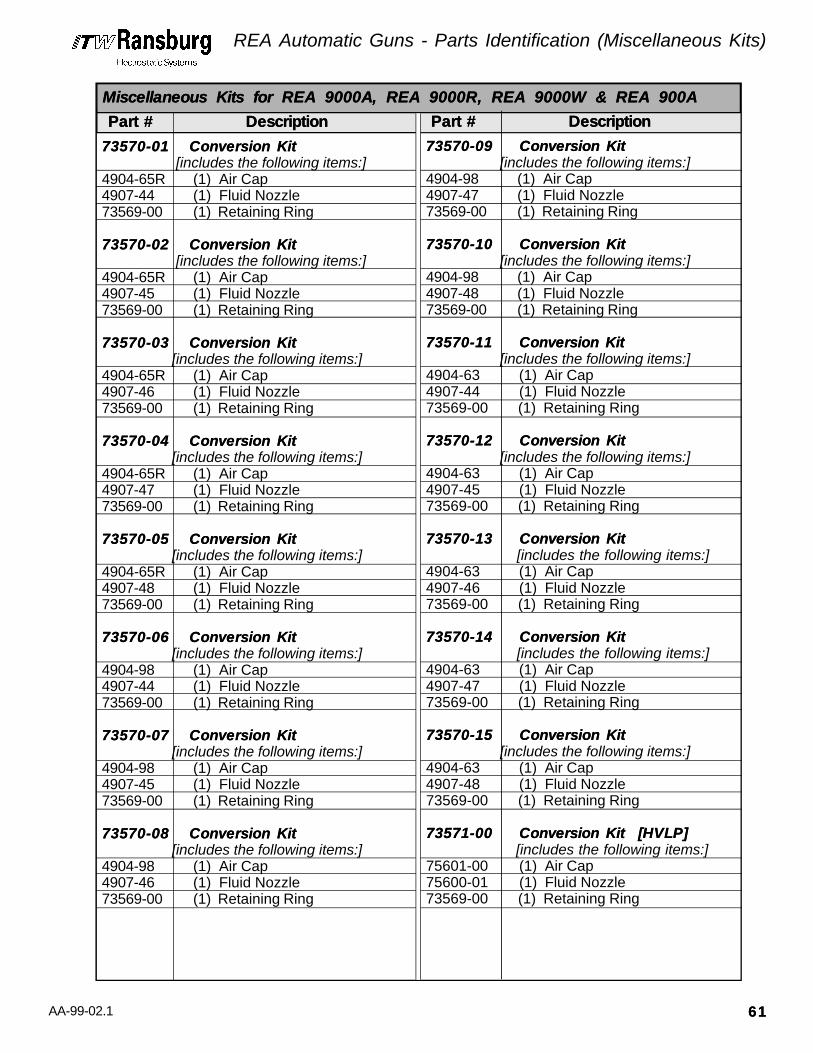
AA-99-02.1
73570-01 Conversion Kit73570-01 Conversion Kit [includes the following items:]4904-65R (1) Air Cap4907-44 (1) Fluid Nozzle73569-00 (1) Retaining Ring
73570-02 Conversion Kit73570-02 Conversion Kit [includes the following items:]4904-65R (1) Air Cap4907-45 (1) Fluid Nozzle73569-00 (1) Retaining Ring
73570-03 Conversion Kit73570-03 Conversion Kit [includes the following items:]4904-65R (1) Air Cap4907-46 (1) Fluid Nozzle73569-00 (1) Retaining Ring
73570-04 Conversion Kit73570-04 Conversion Kit [includes the following items:]4904-65R (1) Air Cap4907-47 (1) Fluid Nozzle73569-00 (1) Retaining Ring
73570-05 Conversion Kit73570-05 Conversion Kit [includes the following items:]4904-65R (1) Air Cap4907-48 (1) Fluid Nozzle73569-00 (1) Retaining Ring
73570-06 Conversion Kit73570-06 Conversion Kit [includes the following items:]4904-98 (1) Air Cap4907-44 (1) Fluid Nozzle73569-00 (1) Retaining Ring
73570-07 Conversion Kit73570-07 Conversion Kit [includes the following items:]4904-98 (1) Air Cap4907-45 (1) Fluid Nozzle73569-00 (1) Retaining Ring
73570-08 Conversion Kit73570-08 Conversion Kit [includes the following items:]4904-98 (1) Air Cap4907-46 (1) Fluid Nozzle73569-00 (1) Retaining Ring
73570-09 Conversion Kit73570-09 Conversion Kit [includes the following items:]4904-98 (1) Air Cap4907-47 (1) Fluid Nozzle73569-00 (1) Retaining Ring
73570-10 Conversion Kit73570-10 Conversion Kit [includes the following items:]4904-98 (1) Air Cap4907-48 (1) Fluid Nozzle73569-00 (1) Retaining Ring
73570-11 Conversion Kit73570-11 Conversion Kit [includes the following items:]4904-63 (1) Air Cap4907-44 (1) Fluid Nozzle73569-00 (1) Retaining Ring
73570-12 Conversion Kit73570-12 Conversion Kit [includes the following items:]4904-63 (1) Air Cap4907-45 (1) Fluid Nozzle73569-00 (1) Retaining Ring
73570-13 Conversion Kit73570-13 Conversion Kit [includes the following items:]4904-63 (1) Air Cap4907-46 (1) Fluid Nozzle73569-00 (1) Retaining Ring
73570-14 Conversion Kit73570-14 Conversion Kit [includes the following items:]4904-63 (1) Air Cap4907-47 (1) Fluid Nozzle73569-00 (1) Retaining Ring
73570-15 Conversion Kit73570-15 Conversion Kit [includes the following items:]4904-63 (1) Air Cap4907-48 (1) Fluid Nozzle73569-00 (1) Retaining Ring
73571-00 Conversion Kit [HVLP]73571-00 Conversion Kit [HVLP] [includes the following items:]75601-00 (1) Air Cap75600-01 (1) Fluid Nozzle73569-00 (1) Retaining Ring
Part # DescriptionPart # Description Part # DescriptionPart # Description
Miscellaneous Kits for REA 9000A, REA 9000R, REA 9000W & REA 900AMiscellaneous Kits for REA 9000A, REA 9000R, REA 9000W & REA 900A
REA Automatic Guns - Parts Identification (Miscellaneous Kits)
6161
AA-99-02.1
WARRANTY POLICIESWARRANTY POLICIES
REA Automatic Guns - Warranty Policies
6262
LIMITED WARRANTYLIMITED WARRANTY
ITW Ransburg will replace or repair withoutcharge any part and/or equipment that fallswithin the specified time (see below) because offaulty workmanship or material, provided thatthe equipment has been used and maintained inaccordance with ITW Ransburg's written safetyand operating instructions, and has been usedunder normal operating conditions. Normalwear items are excluded.
THE USE OF OTHER THAN ITW RANS-THE USE OF OTHER THAN ITW RANS-BURG APPROVED PARTS, VOID ALLBURG APPROVED PARTS, VOID ALLWARRANTIES.WARRANTIES.
SPARE PARTS: One hundred and eighty (180)days from date of purchase, except for rebuiltparts (any part number ending in "R") for whichthe warranty period is ninety (90) days.
EQUIPMENT: When purchased as a completeunit, (i.e., guns, power supplies, control units,etc.), is one (1) year from date of purchase.WRAPPING THE APPLICATOR, ASSO-WRAPPING THE APPLICATOR, ASSO-CIATED VALVES AND TUBING, ANDCIATED VALVES AND TUBING, ANDSUPPORTING HARDWARE IN PLASTIC,SUPPORTING HARDWARE IN PLASTIC,SHRINK-WRAP, OR ANY OTHER NON-SHRINK-WRAP, OR ANY OTHER NON-APPROVED COVERING, WILL VOIDAPPROVED COVERING, WILL VOIDTHIS WARRANTY.THIS WARRANTY.
FLUID HANDLING: One (1) year from date ofpurchase (i.e., Totalizer, CCV Valves, etc.).
AIR BEARING ROTATORS: Fifteen thousand(15,000) hours or three (3) years, whichever oc-curs first. Warranty period begins on the date ofpurchase.
ITW RANSBURG'S ONLY OBLIGATIONITW RANSBURG'S ONLY OBLIGATIONUNDER THIS WARRANTY IS TO RE-UNDER THIS WARRANTY IS TO RE-PLACE PARTS THAT HAVE FAILED BE-PLACE PARTS THAT HAVE FAILED BE-CAUSE OF FAULTY WORKMANSHIPCAUSE OF FAULTY WORKMANSHIPOR MATERIALS. THERE ARE NO IM-OR MATERIALS. THERE ARE NO IM-PLIED WARRANTIES NOR WARRAN-PLIED WARRANTIES NOR WARRAN-TIES OF EITHER MERCHANTABILITYTIES OF EITHER MERCHANTABILITYOR FITNESS FOR A PARTICULAROR FITNESS FOR A PARTICULARPURPOSE. ITW RANSBURG ASSUMESPURPOSE. ITW RANSBURG ASSUMESNO LIABILITY FOR INJURY, DAMAGENO LIABILITY FOR INJURY, DAMAGETO PROPERTY OR FOR CONSEQUEN-TO PROPERTY OR FOR CONSEQUEN-TIAL DAMAGES FOR LOSS OF GOOD-TIAL DAMAGES FOR LOSS OF GOOD-WILL OR PRODUCTION OR INCOME,WILL OR PRODUCTION OR INCOME,WHICH RESULT FROM USE OR MIS-WHICH RESULT FROM USE OR MIS-USE OF THE EQUIPMENT BY PUR-USE OF THE EQUIPMENT BY PUR-CHASER OR OTHERS.CHASER OR OTHERS.
EXCLUSIONS:EXCLUSIONS:
If, in ITW Ransburg's opinion the warranty itemin question, or other items damaged by this partwas improperly installed, operated or main-tained, ITW Ransburg will assume no responsi-bility for repair or replacement of the item oritems. The purchaser, therefore will assume allresponsibility for any cost of repair or replace-ment and service related costs if applicable.

AA-99-02.1
PAINT AND SOLVENT SPECIFICATIONSPAINT AND SOLVENT SPECIFICATIONSAEROBELL IIAEROBELL IITMTM******
AEROBELLAEROBELL ®®
AEROBELL 33AEROBELL 33 TMTM
RMA-101RMA-101 TMTM
18 TO 30 SEC.1 MΩ TO ∞1000 cc/min
TURBODISKTURBODISK TMTMNO. 2 HAND GUNNO. 2 HAND GUNREMREM®® / M90 / M90TMTMREAREA®® / EFM / EFMTMTM
RECOMMENDED VISCOSITY USING A ZAHN NO. 2PAINT ELECTRICAL RESISTANCE**RECOMMENDED DELIVERY (UP TO)
18 TO 30 SEC.1 MΩ TO ∞1500 cc/min
20 TO 60 SEC.1 TO 1 MΩ180 cc/min
20 TO 60 SEC.1 MΩ TO ∞1000 cc/min
20 TO 60 SEC.1 MΩ TO ∞500 cc/min
APPENDIXAPPENDIX
NOTE: NOTE: This page provides resistivity determination and control information that we feel is necessary whenusing ITW Ransburg equipment.
** CAS Number: Chemical Abstract Service Number.**** Using the Ransburg Meter.****** Solvent Base Configuration Only.† † Information Obtained From: http://solvdb.ncms.orgEvaporation Rate is Based Upon Butyl Acetate Having a Rate of 1.0Evaporation Rate is Based Upon Butyl Acetate Having a Rate of 1.0
© © 2001, ITW Ransburg
DICHLOROMETHANEMETHYL ACETATEVM & P NAPHTHA
ACETONEBENZENE
ETHYL ACETATE2-BUTANONE
ISO-PROPYL ACETATEISOPROPYL ALCOHOL
2-PENTANONEMETHANOL
PROPYL ACETATETOLUOL
METHYL ISOBUTYL KETONEISOBUTYL ACETATE
ETHANOLBUTYLBUTYL ACET ACETAATETE
ETHYLBENZENE1-PROPANOL2-BUTANOL
XYLOLAMYL ACETATE
2-METHYLPROPANOLMETHYL AMYL ACETATE5-METHYL-2-HEXANONE
1-BUTANOL2-ETHOXYETHANOL
2-HEPTANONECYCLOHEXANONE
AROMATIC-100DIISOBUTYL KETONE
1-PENTANOLDIACETONE ALCOHOL
2-BUTOXYETHANOLCYCLOHEXANOLAROMATIC-150AROMATIC-200
Methylene Chloride
Naptha
MEK
IPAMPK
Methyl Alcoholn-Propyl Acetate
TolueneMIBK
Ethyl Alcohol
n-Propyl Alcoholsec.-Butyl Alcohol
Xylene
iso-Butyl Alcohol
MIAKn-Butyl Alcohol
MAK
SC#100DIBK
Amyl Alcohol
Butyl Cellosolve
SC#150
Chlorinated SolventsEsters
Aliphatic HydrocarbonsKetones
Aromatic HydrocarbonsEsters
KetonesEsters
AlcoholsKetonesAlcoholsEsters
Aromatic HydrocarbonsKetonesEsters
AlcoholsEstersEsters
Aromatic HydrocarbonsAlcoholsAlcohols
Aromatic HydrocarbonsEsters
AlcoholsEsters
KetonesAlcohols
Glycol EthersKetonesKetones
Aromatic HydrocarbonsKetonesAlcoholsKetones
Glycol EthersAlcohols
Aromatic HydrocarbonsAromatic Hydrocarbons
75-09-279-20-9
803-232-467-64-171-43-2
141-78-678-93-3
108-21-467-63-0
107-87-967-56-1
109-60-4108-88-3108-10-1110-19-064-17-5
123-86-4123-86-4100-41-471-23-878-92-2
133-02-07628-63-778-83-1
108-84-9110-12-371-36-3
110-80-5110-43-0108-94-1
108-83-871-41-0
123-42-2111-76-2108-93-0
14.514.511.811.810105.65.65.15.13.93.93.83.83.43.42.52.52.52.52.12.12.12.11.91.91.61.61.51.51.41.41.01.0.89.89.86.86.81.81.80.80.67.67.62.62.50.50.50.50.43.43.38.38.40.40.29.29.20.20.19.19.15.15.12.12.07.07.05.05
.004.004
.003.003
HIGHLOWHIGHLOWHIGH
MEDIUMMEDIUM
LOWLOW
MEDIUMLOWLOWHIGH
MEDIUMLOWLOWLOWLOWHIGHLOWLOWHIGH
MEDIUMLOWLOW
MEDIUMLOWLOW
MEDIUMMEDIUM
HIGHMEDIUM
LOWLOWLOWLOWHIGHHIGH
FFAASSTTEERR
⇓⇓
SSLLOOWWEERR
⇑⇑EVAP.EVAP.RATERATE††
CHEMICALCHEMICALNAMENAME
COMMONCOMMONNAMENAME
CATEGORYCATEGORY *CAS*CASNUMBERNUMBER
ELECTRICALELECTRICALRESISTANCE**RESISTANCE**
GUIDE TO USABLE SOLVENT SELECTIONGUIDE TO USABLE SOLVENT SELECTION
REA Automatic Guns - Appendix
6363

AA-99-02.1
VISCOSITY CONVERSION CHARTVISCOSITY CONVERSION CHARTP
ois
eP
ois
e
.1
.15
.2
.25
.3
.4
.5
.6
.7
.8
.9
1.0
1.2
1.4
1.6
1.8
2.0
2.2
2.4
2.6
2.8
3.0
3.2
3.4
3.6
3.8
4.0
4.2
4.4
4.6
4.8
5.0
5.5
6.0
7.0
8.0
9.0
10.0
11.0
12.0
Ce
nti
po
ise
Ce
nti
po
ise
Du
Po
nt
Du
Po
nt
Par
lin
7P
arlin
7
Du
Po
nt
Du
Po
nt
Pa
rlin
1
0P
arl
in
10
Fis
her
1F
ishe
r 1
Fis
her
2F
ishe
r 2
For
d C
up 3
For
d C
up 3
For
d C
up 4
For
d C
up 4
Gar
dner
-
Gar
dner
-
Ho
ldt
Bu
bb
leH
old
t B
ub
ble
Gar
dner
-
Gar
dner
-
Lit
ho
gra
ph
icL
ith
og
rap
hic
Kre
bs
Un
itK
reb
s U
nit
KU
KU
Sa
ybo
ltS
ayb
olt
Un
ive
rsa
l S
SU
Un
ive
rsa
l S
SU
Zah
n 1
Zah
n 1
Zah
n 2
Zah
n 2
Zah
n 3
Zah
n 3
Zah
n 4
Zah
n 4
Zah
n 5
Zah
n 5
Se
ars
Se
ars
Cra
ftsm
an
C
up
Cra
ftsm
an
C
up
Din
Cup
4D
in C
up 4
10
15
20
25
30
40
50
60
70
80
90
100
120
140
160
180
200
220
240
260
280
300
320
340
360
380
400
420
440
460
480
500
550
600
700
800
900
1000
1100
1200
27
30
32
37
43
50
57
64
11
12
13
14
15
16
17
18
20
22
23
25
30
32
37
41
45
20
25
30
35
39
50
15
17
18
21
24
29
33
39
44
50
62
12
15
19
25
29
33
36
41
45
50
58
66
5
8
10
12
14
18
22
25
28
31
32
34
41
45
50
54
58
62
65
68
70
74
A-4
A-3
A-2
A-1
A
B
C
D
E
F
G
H
I
J
K
L
M
N
O
P
Q
R
S
T
U
V
W
000
00
0
30
33
35
37
38
40
43
46
48
50
52
54
56
58
59
60
62
64
66
67
68
69
71
74
77
81
85
88
92
60
80
100
130
160
210
260
320
370
430
480
530
580
690
790
900
1000
1100
1200
1280
1380
1475
1530
1630
1730
1850
1950
2050
2160
2270
2380
2480
2660
2900
3375
3380
4300
4600
5200
5620
30
34
37
41
44
52
60
68
16
17
18
19
20
22
24
27
30
34
37
41
49
58
66
74
82
10
12
14
16
18
20
23
25
27
30
32
34
36
39
41
43
46
48
50
52
54
57
63
68
10
11
13
14
16
17
18
20
21
22
24
25
26
28
29
30
32
33
34
36
37
40
44
51
58
64
10
11
12
13
14
15
16
17
18
19
20
21
22
23
24
25
27
30
35
40
45
49
55
59
19
20
21
23
24
26
27
31
34
38
40
44
10
11
12
13
14
15
16
18
21
23
25
27
31
34
38
43
46
51
55
58
63
68
72
76
82
86
90
95
100
104
109
112
124
135
160
172
195
218
REA Automatic Guns - Appendix
6464

AA-99-02.1
Po
ise
Po
ise
13.0
14.0
15.0
16.0
17.0
18.0
19.0
20.0
21.0
22.0
23.0
24.0
25.0
30.0
35.0
40.0
45.0
50.0
55.0
60.0
65.0
70.0
75.0
80.0
85.0
90.0
95.0
100.0
110.0
120.0
130.0
140.0
150.0
160.0
170.0
180.0
190.0
200.0
300.0
Ce
nti
po
ise
Ce
nti
po
ise
Du
Po
nt
Du
Po
nt
Par
lin
7P
arlin
7
Du
Po
nt
Du
Po
nt
Pa
rlin
1
0P
arl
in
10
Fis
her
1F
ishe
r 1
Fis
her
2F
ishe
r 2
For
d C
up 3
For
d C
up 3
For
d C
up 4
For
d C
up 4
Gar
dner
-
Gar
dner
-
Ho
ldt
Bu
bb
leH
old
t B
ub
ble
Gar
dner
-
Gar
dner
-
Lit
ho
gra
ph
icL
ith
og
rap
hic
Kre
bs
Un
itK
reb
s U
nit
KU
KU
Sa
ybo
ltS
ayb
olt
Un
ive
rsa
l S
SU
Un
ive
rsa
l S
SU
Zah
n 1
Zah
n 1
Zah
n 2
Zah
n 2
Zah
n 3
Zah
n 3
Zah
n 4
Zah
n 4
Zah
n 5
Zah
n 5
Se
ars
Se
ars
Cra
ftsm
an
C
up
Cra
ftsm
an
C
up
Din
Cup
4D
in C
up 4
1300
1400
1500
1600
1700
1800
1900
2000
2100
2200
2300
2400
2500
3000
3500
4000
4500
5000
5500
6000
6500
7000
7500
8000
8500
9000
9500
10000
11000
12000
13000
14000
15000
16000
17000
18000
19000
20000
30000
X
Y
Z
Z-1
Z-2
Z-3
Z-4
Z-5
Z-6
1
2
3
4
5
95
96
98
100
101
103
105
109
114
121
129
133
136
6100
6480
7000
7500
8000
8500
9000
9400
9850
10300
10750
11200
11600
14500
16500
18500
21000
23500
26000
2800
30000
32500
35000
37000
39500
41000
43000
46500
51000
55005
60000
65000
67500
74000
83500
83500
88000
93000
140000
64
Note: Note: All viscosity comparisons are as accurate as possible with existing information. Comparisons are made with a material having a specific gravity of 1.0.
VISCOSITY CONVERSION CHART (Continued)VISCOSITY CONVERSION CHART (Continued)
REA Automatic Guns - Appendix
6565

AA-99-02_EFS
LengthLength
VOLUMETRIC CONTENT OF HOSE OR TUBEVOLUMETRIC CONTENT OF HOSE OR TUBE(English Units)(English Units)
I .D.I .D.
(inches)(inches) 5ft. (60") 5ft. (60")
1/8
3/16
1/4
5/16
3/8
1/2
2.4
5.4
9.7
15.1
21.7
38.6
.012
.028
.049
.077
.110
.196
cc/f t .cc/f t .
CrossCross
SeactionSeaction
(sq. in.)(sq. in.) 10ft. (120")10ft. (120") 15ft. (180")15ft. (180") 25ft. (300")25ft. (300") 50ft. (600")50ft. (600")
.003 gal..4 fl. oz..007 gal..9 fl. oz..013 gal.1.6 fl. oz..020 gal.2.5 fl. oz..029 gal.3.7 fl. oz..051 gal.6.5 fl. oz.
.006 gal..8 fl. oz..014 gal.1.8 fl. oz..025 gal.3.3 fl. oz..040 gal.5.1 fl. oz..057 gal.7.3 fl. oz..102 gal.
13.1 fl. oz.
.010 gal.1.2 fl. oz..022 gal.2.8 fl. oz..038 gal.4.9 fl. oz..060 gal.7.6 fl. oz..086 gal.
11.0 fl. oz..153 gal.
19.6 fl. oz.
.016 gal.2.0 fl. oz..036 gal.4.6 fl. oz..064 gal.8.2 fl. oz..100 gal.
12.7 fl. oz..143 gal.
18.4 fl. oz..255 gal.
32.6 fl. oz.
.032 gal.4.1 fl. oz..072 gal.9.2 fl. oz..127 gal.
16.3 fl. oz..199 gal.
25.5 fl. oz..287 gal.
36.7 fl. oz..510 gal.
65.3 fl. oz.
LengthLength
VOLUMETRIC CONTENT OF HOSE OR TUBEVOLUMETRIC CONTENT OF HOSE OR TUBE(Metric Units)(Metric Units)
I .D.I .D.
(mm)(mm) 1.5m1.5m
3.6
5.6
6.8
8.8
10.2
24.6
36.3
60.8
10.2
24.6
36.3
60.8
cc/mcc/m
CrossCross
SectionSection3.0m3.0m 4.5m4.5m 6.0m6.0m 7.5m7.5m
15.3 cc
36.9 cc
54.5 cc
91.2 cc
30.5 cc
73.9 cc
109.0 cc
182.5 cc
45.8 cc
110.8 cc
163.4 cc
273.7 cc
61.1 cc
147.8 cc
217.9 cc
364.9 cc
76.3 cc
184.7 cc
272.4 cc
456.2 cc
(mm ) (mm )22
REA Automatic Guns - Appendix
6666
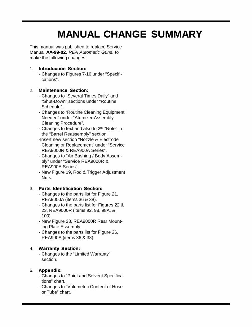
MANUALMANUAL CHANGE SUMMAR CHANGE SUMMARYYThis manual was published to replace ServiceManual AA-99-02AA-99-02, REA Automatic Guns, tomake the following changes:
1. Introduction Section:Introduction Section:- Changes to Figures 7-10 under “Specifi-
cations”.
2. Maintenance Section:Maintenance Section:- Changes to “Several Times Daily” and
“Shut-Down” sections under “RoutineSchedule”.
- Changes to “Routine Cleaning EquipmentNeeded” under “Atomizer AssemblyCleaning Procedure”.
- Changes to text and also to 2nd “Note” inthe “Barrel Reassembly” section.
-Insert new section “Nozzle & ElectrodeCleaning or Replacement” under “ServiceREA9000R & REA900A Series”.
- Changes to “Air Bushing / Body Assem-bly” under “Service REA9000R &REA900A Series”.
- New Figure 19, Rod & Trigger AdjustmentNuts.
3. Parts Identification Section:Parts Identification Section:- Changes to the parts list for Figure 21,
REA9000A (items 36 & 38).- Changes to the parts list for Figures 22 &
23, REA9000R (items 92, 98, 98A, &100).
- New Figure 23, REA9000R Rear Mount-ing Plate Assembly
- Changes to the parts list for Figure 26,REA900A (items 36 & 38).
4. Warranty Section:Warranty Section:- Changes to the “Limited Warranty”
section.
5. Appendix:Appendix:- Changes to “Paint and Solvent Specifica-
tions” chart.- Changes to “Volumetric Content of Hose
or Tube” chart.

Form No. AA-99-02.1Litho in U.S.A.05/02-20
An Illinois Tool Works Company
© 2002 ITW Ransburg Electrostatic Systems, USA
Trademarks indicated with ® are registered with the United States Patent and Trademark Office byITW Ransburg. Patents issued and pending in the United States Patent and Trademark Office.
Teflon® is a registered trademark of the DuPont Company.
*ITW Ransburg Industrial Systems is an ISO 9001 compliant company registered with Factory Mutual.Models and specifications subject to change without notice.
Automotive Systems*Automotive Systems*ITW Automotive Finishing Group48152 West RoadWixom, Michigan 48393Telephone: 248/ 668-8900Fax: 248/ 668-2160Order Desk:Order Desk: Telephone: 877/ 852-7797 Fax: 877/ 852-7796Technical/Service Assistance: Technical/Service Assistance: Telephone: 800/ 626-3565 Fax: 877/ 852-7796
Industrial SystemsIndustrial SystemsITW Ransburg Electrostatic Systems320 Phillips AvenueToledo, Ohio 43612-1493Telephone: 419/ 470-2000Fax: 419/ 470-2270Website: www.itwransburg.comE-Mail: [email protected] Desk:Order Desk: Telephone: 800/ 726-8097 Fax: 800/ 359-2341Technical/Service Assistance: Technical/Service Assistance: Telephone: 800/ 233-3366 Fax: 419/ 470-2071
Service Manual Price: $50.00 (U.S.)Service Manual Price: $50.00 (U.S.)