raspberry pi by example - sample chapter
DESCRIPTION
Chapter No. 5 Introduction to GPIO ProgrammingStart building amazing projects with the Raspberry Pi right out of the boxFor more information: http://bit.ly/23ZcU1iTRANSCRIPT

C o m m u n i t y E x p e r i e n c e D i s t i l l e d
Start building amazing projects with the Raspberry Pi right out of the box
Raspberry Pi By Example
Ashwin Pajankar
Arush Kakkar
Raspberry Pi By Example
This tutorial guide is designed to get you learning all the tricks of the Raspberry Pi by building complete, hands-on hardware projects.
Get started with Pi gaming as you learn how to set up Minecraft, and then program your own game with the help of Pygame. Turn the Pi into your own home security system with complete guidance on setting up a webcam spy camera and OpenCV computer vision for image recognition capabilities. Get to grips with GPIO programming to make a Pi-based glowing LED system, build a fully functioning motion tracker, and more. Finally, construct a complete Internet of Things home automation system with the Raspberry Pi to control your house via Twitter; turn your Pi into a supercomputer by linking multiple boards into a cluster and then add advanced network capabilities for super speedy processing!
Who this book is written forWhat's the best way to learn how to use your Raspberry Pi? By example! If you want something exciting to do while getting to grips with what your Pi can offer, this is the book for you. With both simple and complex projects, you'll create a wide variety of cool toys and functions with your Raspberry Pi.
$ 39.99 US£ 25.99 UK
Prices do not include local sales tax or VAT where applicable
Ashwin PajankarArush Kakkar
What you will learn from this book
Set up your Raspberry Pi and get it ready for some interesting real-life projects
Work with images, videos, webcams, and the Pi camera, and create amazing time-lapse videos
Explore the amazing world of Minecraft Pi
Get to know how to use PiGlow for GPIO programming
Interface your Pi with Grove Sensors and implement IoT applications
Build your own cluster with Raspberry Pi
Understand networking and network programming fundamentals
Raspberry Pi B
y Example
P U B L I S H I N GP U B L I S H I N G
community experience dist i l led
Visit www.PacktPub.com for books, eBooks, code, downloads, and PacktLib.
Free Sample

In this package, you will find: The authors biography
A preview chapter from the book, Chapter 5 'Introduction to GPIO
Programming'
A synopsis of the book’s content
More information on Raspberry Pi By Example

About the Authors
Ashwin Pajankar is a software professional and IoT enthusiast with more than 5 years' experience in software design, development, testing, and automation.
He graduated from IIIT Hyderabad, earning an M.Tech in computer science and engineering. He holds multiple professional certifi cations from Oracle, IBM, Teradata, and ISTQB in development, databases, and testing. He has won several awards in college through outreach initiatives, at work for technical achievements, and community service through corporate social responsibility programs.
He was introduced to Raspberry Pi while organizing a hackathon at his workplace, and he's been hooked on Pi ever since. He writes plenty of code in C, Bash, Python, and Java on his cluster of Pis. He's already authored one book on Raspberry Pi and reviewed three other titles related to Python for Packt Publishing.
His LinkedIn Profi le is at https://in.linkedin.com/in/ashwinpajankar.

Arush Kakkar is a computer vision and deep learning researcher and an undergraduate at Delhi Technological University. His primary focus is on autonomous robotics, which includes drones and self-driving cars, and he has been involved in building such systems in different capacities, such as navigation, localization, path planning. He has also leveraged state-of-the art computer vision and deep learning technologies for them. He is the electrical systems head of the Solar Car team of his university, Solaris DTU.
He is currently working on his own driverless car company, CruiseX, which uses deep learning to drive more smoothly and with fewer errors.
You can connect with him through his website at http://www.arushkakkar.com and read up on some of his projects at http://blog.arushkakkar.com.

PrefaceRaspberry Pi is probably one of the most versatile computers ever built. It has been adapted for tasks ranging from home automation, cluster computing, computer vision, and even space missions! What's more is that it enjoys a level of support from the community that is hard to fi nd for any other platform.
Due to this, it is a hacker-friendly device and is a must for anyone who wants to build projects with even a little amount of programming involved. The fact that the basic version of the board costs only $25 means there's a lot of room for experimentation, and users aren't afraid to experiment with and damage it.
In this book, you will fi nd a wide variety of projects, using which anyone can get started with and also build interesting hacks by modifying some of the projects.
What this book coversChapter 1, Introduction to Raspberry Pi and Python, provides an introduction to the Raspberry Pi and booting it up.
Chapter 2, Minecraft Pi, introduces you to Minecraft Pi, which is a preinstalled version of the popular game Minecraft. The fi rst few pages of the chapter deal with the game concept and interface, and further pages deal with programming in-game actions with Python. In the last part of this chapter, you are introduced to the PyGame library and small usage examples of it.
Chapter 3, Building Games with PyGame, is an introduction to the PyGame programming library and game programming. In this chapter, you code your way to your fi rst full-fl edged program on the Raspberry Pi, a game.
Chapter 4, Working with a Webcam and Pi Camera, introduces you to the Pi Camera and regular webcams and how to use them to create real-life applications with the Raspberry Pi. You also create a time-lapse box project in this chapter.

Preface
Chapter 5, Introduction to GPIO Programming, introduces you to the Raspberry Pi B+ and Pi 2 GPIO structure and its real-life usage with LED programming and a third-party add-on, PiGlow.
Chapter 6, Creating Animated Movie with Raspberry Pi, demonstrates the GPIO and camera together by creating a project that requires application of both the concepts in order.
Chapter 7, Introduction to Computer Vision, introduces you to computer vision and image processing with Raspberry Pi. You will create a simple project.
Chapter 8, Creating Your Own Motion Detection and Tracking System, introduces you to advanced concepts in OpenCV, which will be used to implement the next project, which has a higher diffi culty level.
Chapter 9, Grove Sensors and the Raspberry Pi, introduces you to the Grove shield and Grove sensors and their interfacing with Raspberry Pi. Grove Sensors are third-party sensors for Raspberry Pi and Arduino that can be used for environment sensing.
Chapter 10, Internet of Things with the Raspberry Pi, looks at creating home automation and Internet of Things applications with the Raspberry Pi.
Chapter 11, Build Your Own Supercomputer with the Raspberry Pi, deals with making clusters of Raspberry Pi 2s, using MPICH2 and MPI for Python to write parallel programs for the clusters, and running N-body simulation.
Chapter 12, Advanced Networking with the Raspberry Pi, shows you how to improve your cluster of Pis by adding advanced networking capabilities such as DNS and DHCP. We use of existing cluster for this and make it better.
Chapter 13, Setting Up a Web Server on the Raspberry Pi, delves into installing PHP, MySQL, and WordPress on our Raspberry Pi to use it as a web server.
Chapter 14, Network Programming in Python with the Pi, teaches you how to use Python to learn the basics of network programming and also create network utilities such as Telnet and chat applications on the Raspberry Pi.
Appendix, Newer Raspberry Pi Models, briefl y introduces you to some of the newest members of the Raspberry Pi family, namely the Raspberry Pi Zero and the Raspberry Pi 3.

[ 73 ]
Introduction to GPIO Programming
In the previous chapter, we learned how to use a webcam and Pi Camera to capture images and videos. We also built a timelapse photography box to get experience about the real-life uses of what we learned.
In this chapter, we are going to adopt a hardware-focused approach and use Raspberry Pi's most talked about feature: its GPIO (short for General Purpose Input Output) pins. Specifi cally, we will learn how to use GPIO pins on Raspberry Pi B+ and Raspberry Pi 2. Once we get familiar with the use of the pins, we will also build a real-life project to further our knowledge of their use. The following topics will be covered in the chapter:
• Introducing GPIO pins• Blinking an LED with GPIO pins• Adding push button controls• Learning about PiGlow

Introduction to GPIO Programming
[ 74 ]
Introducing GPIO pinsMost of you may know where GPIO pins are located on the Raspberry Pi. If not, the following illustration will make it clear:
The following is a top view of the Raspberry Pi B+ board, which will help you see the components even more clearly:

Chapter 5
[ 75 ]
The following diagram of the GPIO pins gives information about the naming convention and the function of each of the pins:
Note that the GPIO pins of Raspberry Pi B+ and Pi 2 are the same.
As you can see from the preceding diagram, there are four power pins, two for 3.3V and two for 5V, 8 ground pins distributed across the rail, 26 GPIO pins—some of which also provide protocols such as UART, SPI, PCM, PWM, I2C—and two pins reserved for accessing the EEPROM via I2C.
GPIO pins can be ON or OFF and HIGH or LOW. When a 3.3V pin is high, it outputs 3.3V, and when it is low, it outputs 0V. A GPIO pin can act as an input as well as an output but not both at the same time. To use it as an output is as simple as setting the pin state to ON or OFF.

Introduction to GPIO Programming
[ 76 ]
To use GPIO pins, we will use a simple Python library called RPi.GPIO, which takes out all the effort and makes it easy to confi gure and use the pins. Confi guring a pin to be an output or an input requires only a single statement. We will now see how to manipulate GPIO pins to use this library.
Take care to use Broadcom chip names for the GPIO pins. You can look this up in the diagram given earlier. If our pin has been set to the output mode, we can also set its activation or voltage level to HIGH or LOW. Keep in mind that in the case of the Raspberry Pi, high voltage is represented by 3.3V, and low voltage is represented by 0V. It will be damaging for the Raspberry Pi if you connect a 5V device to its 3.3V GPIO pins. However, you can use two 5V pins to power a small add-on, such as an LED or a buzzer. If you plan to use anything that requires more current, ensure that you use a separate power supply as the Pi can supply only a limited current. So, directly powering a motor from the Pi is not a good idea.
You can do amazing things with the input pins. Not only can you take inputs from a button, but you can also connect sensors, such as a light sensor, smoke sensor, and temperature sensor to build all kinds of amazing projects. You can also use an Internet-connected Raspberry Pi to control your outputs from anywhere in the world! But the networking part is outside the scope of this chapter.
A simple project at this point would be to build a simple LED blinking program. So let's see how that works!
Building an LED BlinkerFor this project, you will require a humble low-power LED with the color of your choice, which can be obtained at your local hardware store or can be ordered online. The Raspberry Pi will act as both the switch and the power supply. In fact, we will power and switch the LED from the same output pin. The complete code and the wiring diagram has been given here. We will learn the code line by line following the diagram. Connect your LED to the Raspberry Pi, as shown. In an LED, the longer leg is the positive pin by convention, and the shorter leg has negative polarity. So take care to connect it the right way, or it might get damaged:
import RPi.GPIO as GPIOimport time
GPIO.setmode(GPIO.BOARD)GPIO.setup(7, GPIO.OUT)
def Blink(speed): GPIO.output(7,True) time.sleep(speed)

Chapter 5
[ 77 ]
GPIO.output(7,False) time.sleep(speed) GPIO.cleanup()
Blink(1)
Once you've connected the LED as shown, go ahead and save the code as prog1.py, and execute the following command:
python prog1.py
If everything goes according to the plan, you should now see your LED blinking. Now we will analyze the code to see what exactly was done.
As usual, we begin the Python program by importing the required dependencies. RPi.GPIO is the Python library that provides the API that allows us to use GPIO pins. It is preinstalled on the Raspbian operating system. Then, we import the time module that will provide us with the delay for the blink.

Introduction to GPIO Programming
[ 78 ]
GPIO.setmode() sets the addressing mode of the GPIO pins. There are two modes, namely BOARD and BCM. The BOARD mode addresses the pins by the numbering given on the board. For example, in the preceding GPIO diagram, the GPIO04 is pin 7. The other mode is BCM and it defi nes the pins according to the Broadcom Firmware on the Raspberry Pi. So, the GPIO04 pin will be referred to as 4 rather than 7. The next statement, GPIO.setup(), confi gures the specifi ed pin to be an output or input depending on the argument.
Now, we'll move on to the main chunk of the code, which is the Blink() function. The GPIO.output() function takes two arguments: the pin number and the logical operation to be performed. In the fi rst output statement, we set pin 7 to HIGH, and then in the second output statement, we set it to LOW. In between these functions, we have the sleep() function from the time package, which takes only one argument: the time in seconds. It does nothing but delay the execution of the next statement by the input number of seconds, which could also be fractions such as 0.5 or 0.2. The last statement in the Blink()function is the cleanup() function, which resets all the ports you have used back to the input mode. This prevents the pin from being damaged when you have set HIGH as an output and then accidentally connect it to ground, which would short-circuit the port. So, it's safer to leave the ports as inputs.
Connecting a buttonAs we saw in the previous section, connecting an LED to a GPIO pin was easy, and the code was simple. In this section, we will use the same general code in order to program a GPIO pin to take an input from the button and if the button is pressed, light the LED that we have already connected in the previous section. We will now take a look at the code and then explain those lines that were not encountered in the previous section:
import RPi.GPIO as GPIOimport time
GPIO.setmode(GPIO.BOARD)
GPIO.setup(12, GPIO.IN, pull_up_down = GPIO.PUD_UP)GPIO.setup(7, GPIO.OUT)
while True: input_state = GPIO.input(12)
if input_state == False: print('Button Pressed')GPIO.output(7, True)

Chapter 5
[ 79 ]
else : print('Button Not Pressed')GPIO.output(7, False)
Now, save the code as prog2.py and run it with the following command:
python prog2.py
In this section, we confi gure pin #12 (by board numbering) to be an output via the same GPIO.setup() statement that we used in the previous section. But here, we have an extra argument, pull_up_down=GPIO.PUD_UP. This means that the internal resistor for the GPIO pin is being pulled up to 3.3V, and it will return False when the button is pressed. This is a little counter-intuitive, but without pulling up or down, the input will be left "fl oating", which means that the Pi will not be able to determine a button press simply because it does not have anything to compare the voltage level to!
Now we enter the infi nite while loop, where it checks for the button state using the GPIO.input()function. As mentioned earlier, if the button is pressed, input_state will return False and the LED will be lit up. If, instead, the button is not pressed anymore, the LED will go off!
Simple, isn't it? Let's move on a more complicated add-on.

Introduction to GPIO Programming
[ 80 ]
Installing PiGlowThe following fi gure shows the PiGlow board:
Since we have learned how to control an LED and a button via Raspberry Pi GPIO pins, we will now move on to a module called PiGlow, which is an add-on board for the Raspberry Pi and provides 18 individually controlled LEDs, and which you can use via a provided library. We will now proceed to install the software requirements for PiGlow by using a script provided by Pimoroni itself. To install PiGlow, run the following command in a new terminal:
curl get.pimoroni.com/piglow | bash
To check whether PiGlow has been installed properly, open a Python terminal and execute the following command:
import piglow
If it is successful, then continue.
To confi rm whether I2C has been enabled, open the Raspberry Pi confi guration tool by entering the following command:
sudo raspi-config
Chapter 5
[ 81 ]
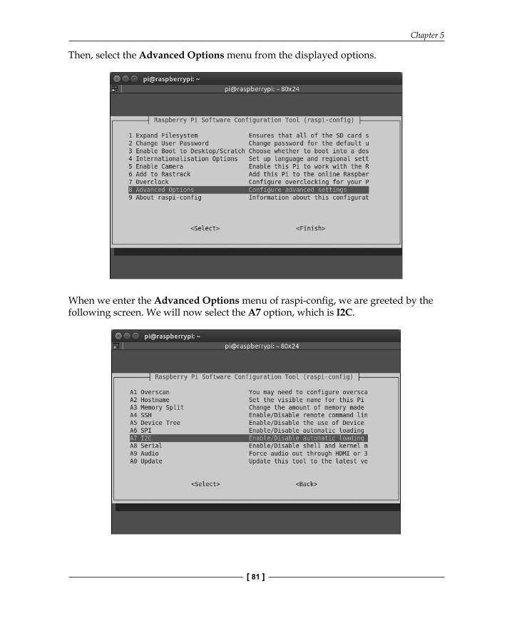
Then, select the Advanced Options menu from the displayed options.
When we enter the Advanced Options menu of raspi-confi g, we are greeted by the following screen. We will now select the A7 option, which is I2C.

Introduction to GPIO Programming
[ 82 ]
Once we select the I2C menu, the following display will be shown:
Select Yes for both the previous screen and the following one:

Chapter 5
[ 83 ]
Using PiGlowPiGlow has a set of female GPIO railings, which cover the Raspberry Pi's male GPIO rails. In case of Raspberry Pi 2 and B+, the size of the railing in PiGlow is shorter, so we need to make sure that PiGlow is attached to only lower numbered pins on the Raspberry Pi.
You can fi nd out more about PiGlow on the Pimoroni website at https://shop.pimoroni.com/products/piglow.
We can now proceed to control the LEDs on the PiGlow board. Open up a Python terminal and execute the following statements in a sequential order:
import piglowpiglow.red(64)
Here, we import the particular library in Python fi rst. The red() method selects all the red LEDs on the PiGlow board. It takes only one argument, the intensity of the LEDs, which can be a number from 0 to 255. You can also try to pass the number 255 to the red() method to see how it affects the intensity of the LED. In this case, passing 0 would mean that the LED is off. But once we execute the earlier two statements, nothing will happen. We have to update the PiGlow with our changes by issuing the following command:
piglow.show()
Why? Because if we are setting up a pattern, lighting the LED costs time and resources. However, we can use the show method to draw the changes instantaneously. If you fi nd this strange, you can turn this off by turning auto-update on with the following command:
piglow.auto_update = True
Similar to the red() method used earlier, we also have functions to control different colors, namely white, blue, green, yellow, and orange.
But maybe we want to control each arm of the light rather than all the lights of a single color. Well, we can do that with the arm() function! Take a look:
piglow.arm(0, 128)
Introduction to GPIO Programming
[ 84 ]
The arm function takes two arguments. The fi rst is the number of the arm, and second is the intensity from 0 to 255. For example, in the earlier statement, we set the LEDs of the fi rst arm to an intensity of value 128, which is half of the full level of brightness. Suppose we want to control arbitrary LEDs according to what we specify. We're in luck! The set() function lets us control individual LEDs. It can be used in the following ways:
• set(0, 255): This sets LED 0 to full brightness• set([1, 3, 5], 200): This sets LEDs 1, 3, and 5 to a 200 level of brightness• set(0, [255, 255, 255]): This sets three LEDs starting at 0 index to
full brightness
Now that we have learned the basics of using PiGlow, we will move on to building real-life examples with it. First, we will build a very simple example that looks like the arms of PiGlow are like cycle's spokes. Cool, right? The code is given here, and an explanation is as follows:
import timeimport piglow
i = 0
while True: print(i)piglow.all(0)piglow.set(i % 18, [15, 31, 63, 127, 255, 127, 63, 31, 15])piglow.show()i += 1time.sleep(0.1)
Now save the program as prog1.py and run it with the following command:
python prog1.py
As with every Python program, we fi rst import the dependencies required, which in this case are the time library and the PiGlow library we just installed. Next, we set up the counter to keep track of which LED we want to light up and to execute the bulk of the program we enter into an infi nite while loop. This while loop will continue lighting the LEDs until we kill the program.

Chapter 5
[ 85 ]
First, we print the status of the counter, and then we execute the all() function, which will refresh all the LEDs and ensure that they are turned off at the beginning. We then use the third form of the set() function we saw earlier. This means that starting from the zeroth LED, we light up nine LEDs in an ascending and then descending fashion. The i % 18 will give the remainder of i divided by 18 so that the index of the LED remains within the range of 0 to 18 at all times. Then, we actually show the pattern that we set in the earlier statement via the show() function. Finally, we increment the counter and add a delay of 100 milliseconds.
This pattern gets repeated for every LED, and when done in quick succession, it appears like the spokes are cycling.
This was a very basic example, and now we're ready to move on to a more complicated one, which involves building a binary clock. Let's begin!
Building a binary clockIn this example, we will be building a binary clock using the club PiGlow in which each hour, minute, and second is represented by the three arms of PiGlow. The numbers are displayed in the binary format. We will now look at the code and learn what each part does:
import piglowfrom time import sleepfrom datetime import datetime
piglow.auto_update = True
show12hr = 1ledbrightness = 10
piglow.all(0)
hourcount = 0currenthour = 0

Introduction to GPIO Programming
[ 86 ]
Like the previous example, we import PiGlow and the time libraries, but we also import an additional library, datetime, which gives us the current time. Then, we set the auto-update parameter to true so that PiGlow updates as soon as we make a change to it rather than pushing all the changes at once. We will now set some customization parameters, namely selecting between a 12-hour format or a 24-hour format and the brightness of the LEDs. With that completed, we refresh the LED to the 0 level and set the hour counters. Now we are ready to move on the meat of the code:
while True: time = datetime.now().time()print(str(time))hour = time.hourmin = time.minutesec = time.second
if show12hr == 1: if hour > 12: hour = hour - 12
if currenthour != hour: hourcount = hourcurrenthour = hour
for x in range(6): piglow.led(13 + x, (hour & (1 << x)) * ledbrightness)
for x in range(6): piglow.led(7 + x, (min & (1 << x)) * ledbrightness)
for x in range(6): piglow.led(1 + x, (sec & (1 << x)) * ledbrightness)
if hourcount != 0: sleep(0.5)piglow.white(ledbrightness)sleep(0.5)hourcount = hourcount - 1else : sleep(0.1)
The main code logic is executed inside an infi nite while loop so that the program never stops.

Chapter 5
[ 87 ]
We can now proceed to learn what it is that makes the program tick. First, we must determine the current time, which is done by the datetime.now().time() method. Then, we store each of current hour, minute, and time in a separate variable to display them on separate arms. In the next if statement, we merely check whether we want to display the 12-hour format, and if we do, we subtract 12 from the current hour if it is greater than 12. So, something like 15 will be represented as 3. We have two variables named currenthour and hourcount, which serve to keep the correct hour displayed on the PiGlow arm by decrementing hourcount whenever an hour passes. This way, the hour is decreased, which is necessary if we are using the 12 hour mode. To understand the next statements, which are actually responsible for lighting up the LEDs, we need to understand the logic operators in Python. Some of these are given as follows:
Operation DescriptionX and Y Logical ANDX or Y Logical ORNot X Logical NOTX | Y Bitwise ORX ^ Y Bitwise XORX & Y Bitwise ANDX << Y Bitwise Left ShiftX >> Y Bitwise Right Shift
We are now greeted with a for loop. It has a very simple format as follows:
for (variable) in range(upper limit): The variable is a counter that starts from 0 and gets incremented after each iteration even though we don't explicitly do it. The upper limit, specifi ed as the argument of the range() method, tells the for loop how many iterations are to be executed.
So, for x in range(6), we will set up x as a counter and the loop will be executed exactly six times. This is preferred since each arm has six LEDs, and each of them can be set without having six separate statements.

Introduction to GPIO Programming
[ 88 ]
To understand what the following piece of code does, we will need to delve into the world of binary numbers and bitwise operations. You will also notice that in the argument of the led() function, we are doing a bitwise operation of the numbers. Why so? In the fi rst iteration of the for loop, the value of x is 0, and the binary representation of 1 is 00000001. So, the bitwise shift operation will introduce no change. In the second iteration, however, the value of x will be 1. So, a 1-bit left shift will result in the binary number 00000010, which is the representation of integer 2. Similarly, the third iteration will result in 00000100, which is binary for 4. Now,there is also the bitwise AND operation on the variables holding the values of hours, minutes, and seconds. Consider, for example, that the current hour is 3 p.m. The binary representation will be 00000011. If we do a bitwise AND operation in the fi rst iteration, we get 00000001. This is 1 and it is multiplied with the ledbrightness variable; we light up the 13 + 0 = 13th LED at a brightness of 10. This LED is the fi rst LED of the arm that is represented by hours. Now, doing a bitwise AND in the second iteration, we have hour = 00000011 and 1 << x = 00000010. The result is 00000010, which is the integer 2. This means that the 14th LED will light with a brightness of 20. But in the third iteration, since 1 << x = 00000100, we get the integer 0 at the output, which means that the 15th LED will not light at all!
Applying the same logic if the time is 4 pm, the 13th LED will not light up, the 14th LED will not light up, but the 15th LED will light up with a brightness of 40. Going in the same direction, we now have an intuitive understanding of how the hours, minutes, and seconds of the binary clock are represented.
Finally, we design the program to fl ash all the white LEDs once the hour fi nishes. We also add 500-ms delays on both sides of the fl ash so that it doesn't appear too sudden. Then, we decrement the hour count and the whole program repeats with the updated time.
Now, save the code as prog3.py and run it with the following command:
python prog3.py
You will now be able to see the hours, minutes, and seconds represented as binary numbers on PiGlow!

Chapter 5
[ 89 ]
SummaryThis chapter was particularly interesting and hands-on because we learned how to manipulate hardware from software! This is exactly the reason why the Raspberry Pi and other boards with GPIO pins have become so popular. They allow you to control real-life hardware applications with software.
We can create potentially unlimited applications for the Pi just by changing the sensors connected to it and tweaking the code. We can build stuff such as home automation systems, security applications, wearable devices, and many more with just this small board! In this chapter, we had the humble beginnings of such projects where we fi rst learned to blink an LED, which wasn't very impressive by itself. Then, we learned how to control that same LED with a button, which was a bit more fun.
Then, we learned about PiGlow and how to connect it to the Raspberry Pi. We learned the various API commands that are used to control the LEDs on PiGlow, and using these commands, we built a binary clock.
With these solid foundations, we then moved on to an even more complicated undertaking, which involved a little theory and a bit of clever programming in Python, which greatly reduced our effort.
In our next chapter, we will learn how to create animated movies. We will use a more software-based approach and make animations such as stop motion.

Where to buy this book You can buy Raspberry Pi By Example from the Packt Publishing website.
Alternatively, you can buy the book from Amazon, BN.com, Computer Manuals and most internet
book retailers.
Click here for ordering and shipping details.
www.PacktPub.com
Stay Connected:
Get more information Raspberry Pi By Example