getting started with raspberry pi zero - sample chapter
TRANSCRIPT
C o m m u n i t y E x p e r i e n c e D i s t i l l e d
Get started with the smallest, cheapest, and highest-utility Pi ever—Raspberry Pi Zero
Getting Started with Raspberry Pi ZeroR
ichard Grim
mett
Getting Started with Raspberry Pi ZeroRaspberry Pi Zero is half the size of Raspberry Pi A, but with twice the utility. It is just 3 cm wide, but packs in every utility required for fully fl edged computing tasks. Some think of Raspberry Pi Zero as a direct competitor to C.H.I.P., the $9 computer.
This practical tutorial will help you quickly get up and running with Raspberry Pi Zero so you can control hardware and software and write simple programs and games. You will learn how to build creative programs and exciting games with little or no programming experience. We cover all the features of Raspberry Pi Zero, and you'll discover how to confi gure software and hardware, write scripts, and control external devices. You will fi nd out how to navigate your way in Raspbian, write simple Python scripts, and create simple DIY programs.
Who this book is written forThis book is for hobbyists and even for programmers who are taking their fi rst steps toward using Raspberry Pi Zero. No programming experience is required, although some Python programming experience might be useful in order to understand the concepts in writing scripts.
$ 29.99 US£ 19.99 UK
Prices do not include local sales tax or VAT where applicable
Richard Grimmett
What you will learn from this book Understand how to download the operating
system and set up Raspberry Pi Zero
Find out how to control the GPIO pins of Raspberry Pi Zero to control LED circuits
Get to grips with adding hardware to the GPIO to control more complex hardware, such as motors
Add USB control hardware to control a complex robot with 12 servos
Include speech recognition so that projects can receive commands
Enable the robot to communicate with the world around it by adding speech output
Control the robot from a distance and see what the robot is seeing by adding wireless communication
Discover how to build a robotic hand and a Quadcopter
Getting Started w
ith Raspberry Pi Zero
P U B L I S H I N GP U B L I S H I N G
community experience dist i l led
Visit www.PacktPub.com for books, eBooks, code, downloads, and PacktLib.
Free Sample
In this package, you will find: The author biography
A preview chapter from the book, Chapter 4 'Building and controlling a simple
wheeled robot'
A synopsis of the book’s content
More information on Getting Started with Raspberry Pi Zero
About the Author
Richard Grimmett has always been fascinated by computers and electronics since his very fi rst programming project that used Fortran on punch cards. He has a bachelor's and master's degree in electrical engineering and a PhD in leadership studies. He also has 26 years of experience in the radar and telecommunications industries, and even has one of the original brick phones. He now teaches computer science and electrical engineering at the Brigham Young University, Idaho, where his offi ce is fi lled with his numerous robotics projects.
PrefaceFor many years, robots and other advanced electronic wonders could only be seen on the television, movies, or in university or military labs. In recent years, however, the availability of new and inexpensive hardware and also free and open source software, has provided the opportunity for almost anyone with a little technical knowledge and imagination to build these technical wonders. The fi rst wave of projects were fueled by Arduino, an inexpensive and simple-to-program microcontroller. The next wave was carried further by the introduction of the Raspberry Pi, an even more capable processor powered by the Linux operating system.
Now there is an even less expensive, powerful microprocessor: the Raspberry Pi Zero. This little processor packs a processor powerful enough to run Linux into a small and even less expensive package. This capability, coupled with some additional power, inexpensive hardware, and free open source software provides a platform for projects that range from simple wheeled robots to advanced fl ying machines.
What this book coversChapter 1, Setting Started with Raspberry Pi Zero, is designed to go through the details of setting up a useful development environment on Raspberry Pi Zero. The chapter begins with a discussion of how to connect power and continues through setting up a full system, confi gured and ready to be connected to any of the amazing devices and SW capabilities to develop advanced robotics applications.
Chapter 2, Programming Raspberry Pi Zero, reviews, for those who are already familiar, basic Linux, editing, and programming techniques that will be useful through the rest of the book. You'll learn how to interact from the command line, how to create and edit a fi le using an editor, and basic Python programming.
Preface
Chapter 3, Accessing the GPIO Pins on Raspberry Pi Zero, discusses the GPIO capabilities of Raspberry Pi Zero by building and controlling some simple LED circuits.
Chapter 4, Building and Controlling a Simple Wheeled Robot, discusses one of the amazing things you can do with Raspberry Pi Zero, controlling a simple wheeled robot. This chapter will show you how to add motor control, so you can build your very own autonomous mobile robot.
Chapter 5, Building a Robot That Can Walk, tells us about another impressive robotic project, an autonomous robot that can walk. This is done using servos whose position can be controlled using Raspberry Pi and some additional USB-controlled hardware.
Chapter 6, Adding Voice Recognition and Speech – A Voice Activated Robot, tells us about a voice-activated robot. One of the signifi cant new features of today's computer system is the ability to input commands and provide output without a screen or keyboard. A few years ago, the concept of a computer that can talk and listen was science fi ction, but today it is becoming a standard part of new cell phones. This chapter introduces how Raspberry Pi Zero can both listen to speech and also respond in kind. This is not as easy as it sounds (pun intended) and you'll be exposed to some basic functionality, while also understanding some of the key limitations. You'll take a standard toy and turn it into a responsive robot.
Chapter 7, Adding Raspberry Pi Zero to an RC Vehicle, tells us about another astounding capability of Raspberry Pi Zero, the ability to add "sight" to you projects. Raspberry Pi Zero makes this very easy by supporting open source software and readily available USB webcams. By adding this and a remote control, you can build a remote control vehicle that can go around corners, into rooms, wherever you'd like to go.
Chapter 8, Playing Rock, Paper, or Scissors with Raspberry Pi Zero, tells us about how we can use our toolkit to build and control a robotic hand that can see and respond to the world around it. In this case, you'll program your hand to play rock, paper, and scissors.
Chapter 9, Adding Raspberry Pi Zero to a Quadcopter, talks about the fact that building a robot that can walk, talk, or play air hockey is cool, but one that can fl y is the ultimate goal.
[ 77 ]
Building and Controlling a Simple Wheeled Robot
You should now be familiar with how to program your Raspberry Pi Zero and how to communicate with the outside world with the GPIO. Now, let's actually build a mobile project. Perhaps the easiest way to make your projects mobile is to use a wheeled platform. In this chapter, you will be introduced to some of the basics of manipulating DC motors and using the Raspberry Pi Zero to control the speed and direction of your wheeled platform.
In this chapter, you will learn how to perform the following actions:
• Using the Raspberry Pi Zero GPIO to control a DC motor• Controlling your mobile platform programmatically using the
Raspberry Pi Zero• Implementing some simple path planning algorithms on the
Raspberry Pi Zero
The basic platformYou'll need to add some hardware, specifi cally a wheeled or tracked platform, to make your project mobile. You're going to use a platform that uses differential motion to propel and steer the vehicle. This simply means that, instead of turning the wheels, you're going to vary the speed and direction of the two motors that drive the wheels or tracks. There are a lot of choices. Some come fully assembled while others require some assembly; alternatively you can buy the components and build your own custom mobile platform.
Building and Controlling a Simple Wheeled Robot
[ 78 ]
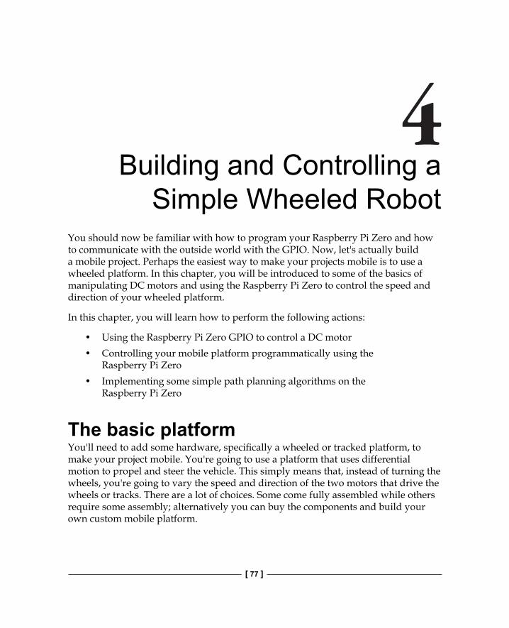
Let's look at a couple of the more popular units that come fully assembled or can be assembled with simple tools (a screwdriver or pliers). The simplest mobile platform is one that has two DC motors, with each motor controlling a single wheel. On the wheeled platform, there is a small wheel or ball in the front or at the back. Here is one example of a wheeled platform, available at many online electronics retailers:
Here is another simple wheeled platform, also sold by many online electronics retailers:
Chapter 4
[ 79 ]
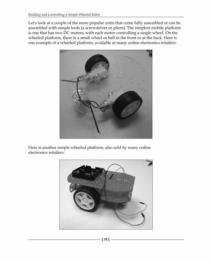
This one also needs to be assembled but it is fairly straightforward. You could also choose a tracked platform instead of a wheeled platform. A tracked platform has more traction but is not as nimble, as it takes a longer distance to turn. Again, manufacturers make pre-assembled units. The following image is an example of a pre-assembled tracked platform made by Dagu. It's called the Dagu Rover 5 Tracked Chassis:
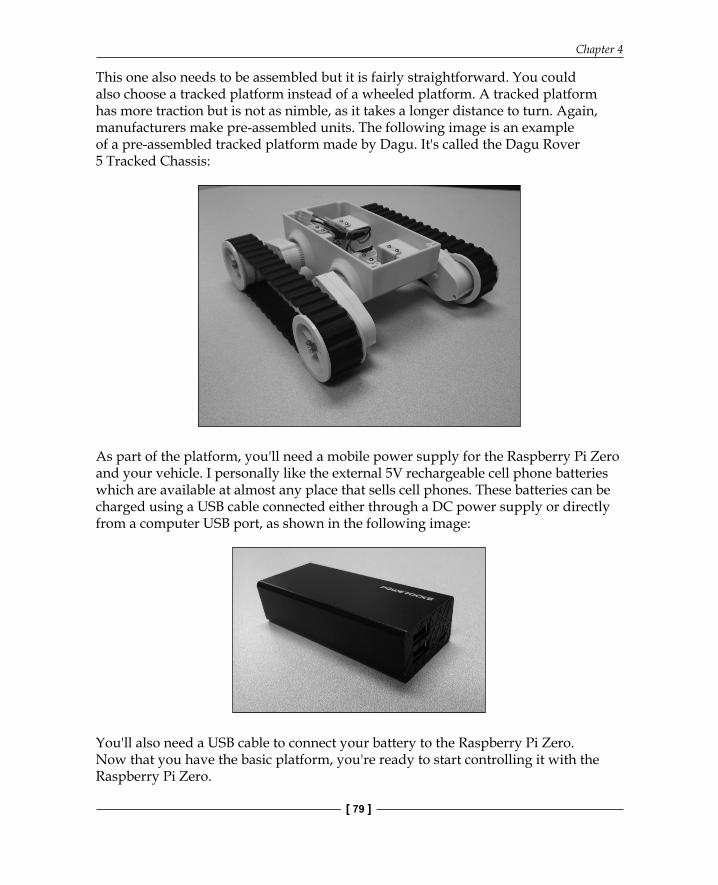
As part of the platform, you'll need a mobile power supply for the Raspberry Pi Zero and your vehicle. I personally like the external 5V rechargeable cell phone batteries which are available at almost any place that sells cell phones. These batteries can be charged using a USB cable connected either through a DC power supply or directly from a computer USB port, as shown in the following image:
You'll also need a USB cable to connect your battery to the Raspberry Pi Zero. Now that you have the basic platform, you're ready to start controlling it with the Raspberry Pi Zero.
Building and Controlling a Simple Wheeled Robot
[ 80 ]
There are two choices here and I'll walk you through both. Firstly, you can use a chip called an H-bridge, plug it into your electronic breadboard, and control the DC motors with connections to the GPIO of the Raspberry Pi Zero. The second choice is to use a dedicated motor controller board designed to connect directly onto the Raspberry Pi Zero's GPIO pins. Let's cover the H-bridge option fi rst.
Controlling an H-bridge interface to the DC motorsThe fi rst step to make the platform mobile is to connect the Raspberry Pi Zero to your H-bridge. This allows you to control the speed of each wheel (or track) independently. Before you get started, let's spend some time learning the basics of motor control. Whether you choose the two-wheeled mobile platform or the tracked platform, the basic movement control is the same. The unit moves by engaging the motors. If the desired direction is straight ahead, the motors are run at the same speed. If you want to turn the unit, the motors are run at different speeds. The unit can turn in a circle if you run one motor forwards and the other one backwards.
The DC motors are fairly straightforward devices. The speed and direction of the motor is controlled by the magnitude and polarity of the voltage applied to its terminals. The higher the voltage, the faster the motor will turn. If you reverse the polarity of the voltage, you can reverse the direction in which the motor turns.
The magnitude and polarity of the voltage are not the only important factors when you think about controlling the motors. The power that your motor can apply to move your platform is also determined by the voltage and the current supplied to its terminals.
There are GPIO (short for general purpose input-output) pins on the Raspberry Pi Zero that you can use to control the voltage and drive your motors. These GPIO pins provide direct access to some of the control lines available from the processor itself. However, the unit cannot obtain enough current and your motors will not be able to generate enough power to move your mobile platform. This can also cause physical damage to your Raspberry Pi Zero board.
Chapter 4
[ 81 ]
You can, however, connect your Raspberry Pi Zero to the DC motors by using an H-bridge DC motor controller. An H-bridge is a fairly simple device. It basically consists of a set of electronic switches and provides the additional functionality of allowing the direction of the current to be reversed so that the motor can be run in either forward or reverse directions.
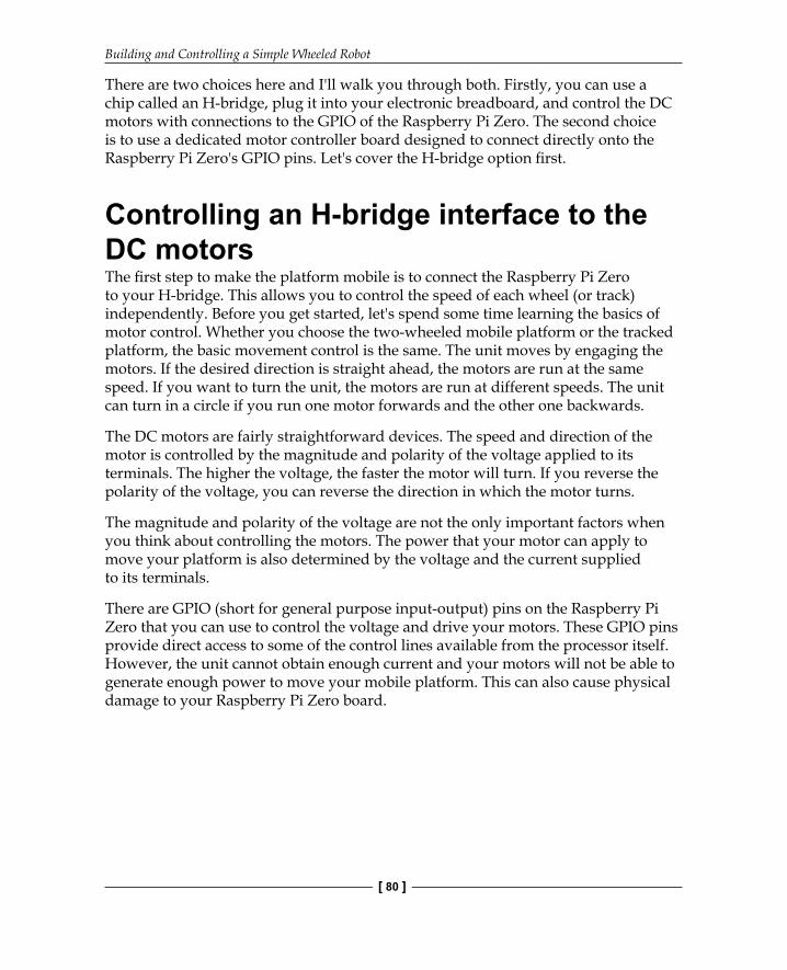
Let's start this example by building the H-bridge circuit and controlling just one motor. To do this, you need to get an H-bridge. One of the most common options is the L293 dual H-bridge chip. This chip allows you to control the direction of the DC motors. These are available at most electronics stores and online. Once you have your H-bridge, build the circuit as shown in the following image with the Raspberry Pi Zero, the motor, the jumper wires, a 4AA battery holder, and a breadboard:
Building and Controlling a Simple Wheeled Robot
[ 82 ]
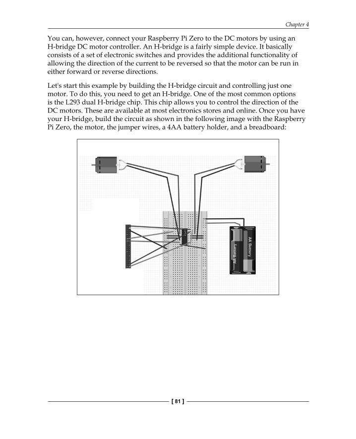
Also, before you start connecting wires, here is an image of the GPIO pins on the Raspberry Pi Zero board:
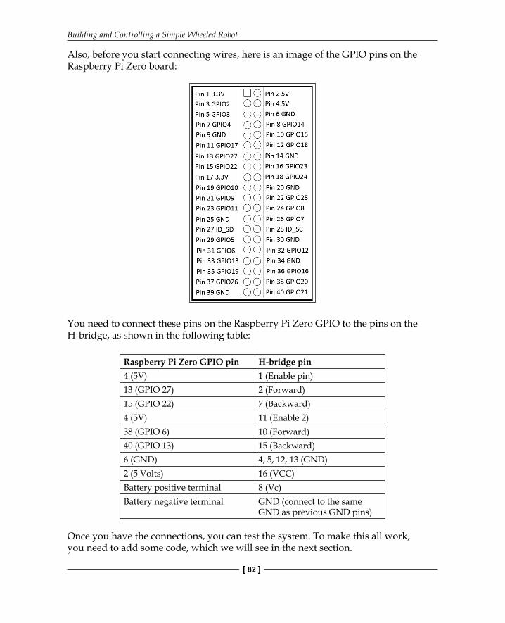
You need to connect these pins on the Raspberry Pi Zero GPIO to the pins on the H-bridge, as shown in the following table:
Raspberry Pi Zero GPIO pin H-bridge pin4 (5V) 1 (Enable pin)13 (GPIO 27) 2 (Forward)15 (GPIO 22) 7 (Backward)4 (5V) 11 (Enable 2)38 (GPIO 6) 10 (Forward)40 (GPIO 13) 15 (Backward)6 (GND) 4, 5, 12, 13 (GND)2 (5 Volts) 16 (VCC)Battery positive terminal 8 (Vc)Battery negative terminal GND (connect to the same
GND as previous GND pins)
Once you have the connections, you can test the system. To make this all work, you need to add some code, which we will see in the next section.
Chapter 4
[ 83 ]
Controlling your mobile platform programmatically using the Raspberry Pi ZeroNow that you have your basic motor controller functionality up and running, you need to connect both motor controllers to the Raspberry Pi Zero. This section will cover this and also show you how to control your entire platform programmatically.
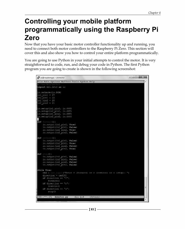
You are going to use Python in your initial attempts to control the motor. It is very straightforward to code, run, and debug your code in Python. The fi rst Python program you are going to create is shown in the following screenshot:
Building and Controlling a Simple Wheeled Robot
[ 84 ]
Perform the following steps to create this program:
To create this program, create a directory called dcmotor in your home directory by typing mkdir dcmotor and then type cd dcmotor. Now, open the fi le by typing emacs dcmotor.py (if you are using a different editor, open a new fi le with the dcmotor.py name).
Now, enter the program. Let's go through the program step by step:
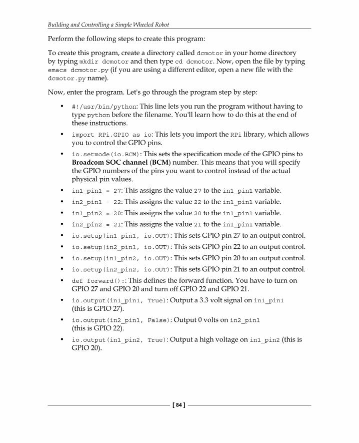
• #!/usr/bin/python: This line lets you run the program without having to type python before the filename. You'll learn how to do this at the end of these instructions.
• import RPi.GPIO as io: This lets you import the RPi library, which allows you to control the GPIO pins.
• io.setmode(io.BCM): This sets the specification mode of the GPIO pins to Broadcom SOC channel (BCM) number. This means that you will specify the GPIO numbers of the pins you want to control instead of the actual physical pin values.
• in1_pin1 = 27: This assigns the value 27 to the in1_pin1 variable.• in2_pin1 = 22: This assigns the value 22 to the in1_pin1 variable.• in1_pin2 = 20: This assigns the value 20 to the in1_pin1 variable.• in2_pin2 = 21: This assigns the value 21 to the in1_pin1 variable.• io.setup(in1_pin1, io.OUT): This sets GPIO pin 27 to an output control.• io.setup(in2_pin1, io.OUT): This sets GPIO pin 22 to an output control.• io.setup(in1_pin2, io.OUT): This sets GPIO pin 20 to an output control.• io.setup(in2_pin2, io.OUT): This sets GPIO pin 21 to an output control.• def forward():: This defines the forward function. You have to turn on
GPIO 27 and GPIO 20 and turn off GPIO 22 and GPIO 21.• io.output(in1_pin1, True): Output a 3.3 volt signal on in1_pin1
(this is GPIO 27).• io.output(in2_pin1, False): Output 0 volts on in2_pin1
(this is GPIO 22).• io.output(in1_pin2, True): Output a high voltage on in1_pin2 (this is
GPIO 20).
Chapter 4
[ 85 ]
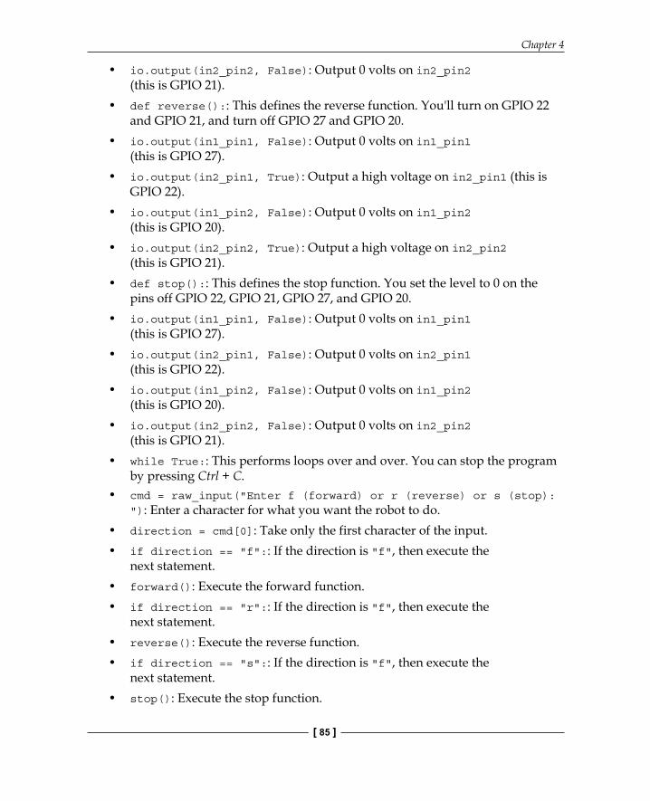
• io.output(in2_pin2, False): Output 0 volts on in2_pin2 (this is GPIO 21).
• def reverse():: This defines the reverse function. You'll turn on GPIO 22 and GPIO 21, and turn off GPIO 27 and GPIO 20.
• io.output(in1_pin1, False): Output 0 volts on in1_pin1 (this is GPIO 27).
• io.output(in2_pin1, True): Output a high voltage on in2_pin1 (this is GPIO 22).
• io.output(in1_pin2, False): Output 0 volts on in1_pin2 (this is GPIO 20).
• io.output(in2_pin2, True): Output a high voltage on in2_pin2 (this is GPIO 21).
• def stop():: This defines the stop function. You set the level to 0 on the pins off GPIO 22, GPIO 21, GPIO 27, and GPIO 20.
• io.output(in1_pin1, False): Output 0 volts on in1_pin1 (this is GPIO 27).
• io.output(in2_pin1, False): Output 0 volts on in2_pin1 (this is GPIO 22).
• io.output(in1_pin2, False): Output 0 volts on in1_pin2 (this is GPIO 20).
• io.output(in2_pin2, False): Output 0 volts on in2_pin2 (this is GPIO 21).
• while True:: This performs loops over and over. You can stop the program by pressing Ctrl + C.
• cmd = raw_input("Enter f (forward) or r (reverse) or s (stop): "): Enter a character for what you want the robot to do.
• direction = cmd[0]: Take only the first character of the input.• if direction == "f":: If the direction is "f", then execute the
next statement.• forward(): Execute the forward function.• if direction == "r":: If the direction is "f", then execute the
next statement.• reverse(): Execute the reverse function.• if direction == "s":: If the direction is "f", then execute the
next statement.• stop(): Execute the stop function.
Building and Controlling a Simple Wheeled Robot
[ 86 ]
You can now run your program. In order to do this, type sudo python ./dcmotor.py. When you enter f, the motors should run forward; with r they should run backward; and with s, they should stop. You can now control the motor with Python. Additionally, you may want to make this program available to run from the command line. Type chmod +x dcmotor.py. If you now type ls (list programs), you'll see that your program is now green, which means that you can execute it directly. Now you can type sudo ./dcmotor.py and the program will run.
Now that you know the basics of commanding your mobile platform, feel free to add even more functions and commands to make your mobile platform move in different ways. Running just one motor will make the platform turn, as will running both motors in opposite directions.
Controlling the speed of your motors with PWMThe previous example either turned the motors on to full speed or turned them off. You may want to confi gure your motors to run at different speeds. This can be done by using Pulse Width Modulation (PWM) to adjust the speed. PWM simply defi nes a way of changing the voltage of the signal by sending a series of pulses of equal value and changing the width of each pulse. The wider the pulse, the higher the average voltage delivered to the receiver. The DC motors that you are using respond to this higher average voltage by spinning faster.
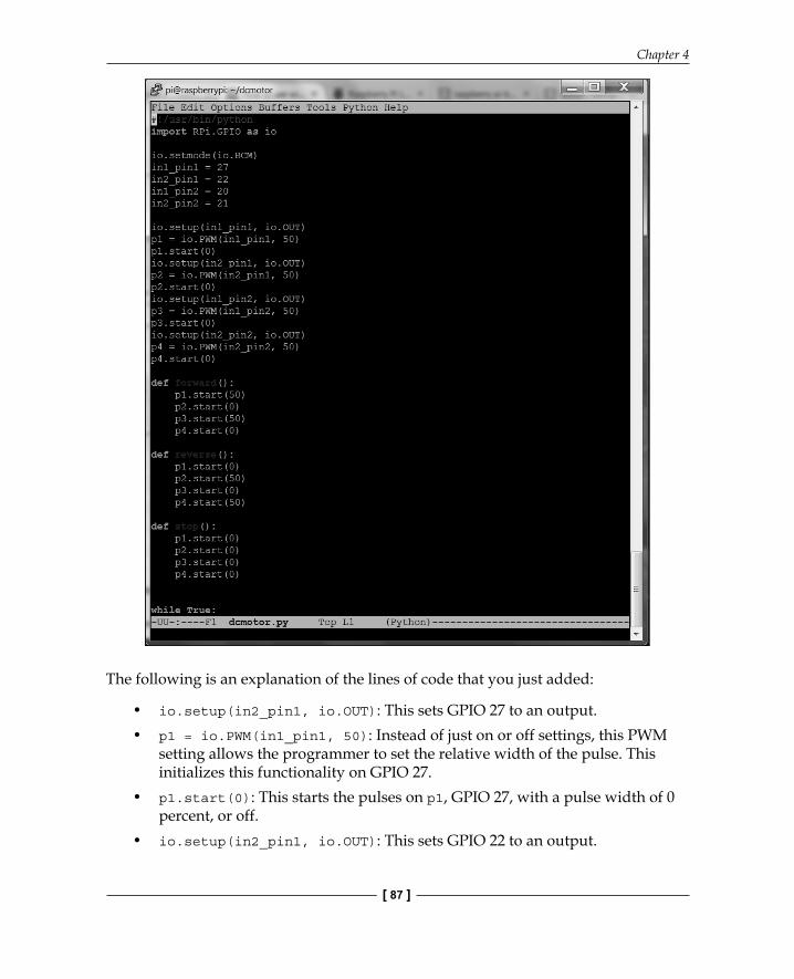
The Raspberry Pi Zero GPIO can create PWM signals. The code snippet to do this is shown in the following screenshot:
Chapter 4
[ 87 ]
The following is an explanation of the lines of code that you just added:
• io.setup(in2_pin1, io.OUT): This sets GPIO 27 to an output.• p1 = io.PWM(in1_pin1, 50): Instead of just on or off settings, this PWM
setting allows the programmer to set the relative width of the pulse. This initializes this functionality on GPIO 27.
• p1.start(0): This starts the pulses on p1, GPIO 27, with a pulse width of 0 percent, or off.
• io.setup(in2_pin1, io.OUT): This sets GPIO 22 to an output.
Building and Controlling a Simple Wheeled Robot
[ 88 ]
• p2 = io.PWM(in2_pin1, 50): This initializes this functionality on GPIO 22.• p2.start(0): This starts the pulses on p2, GPIO 22, with a pulse width of 0
percent, or off.• io.setup(in1_pin2, io.OUT): This sets GPIO 20 to an output.• p3 = io.PWM(in1_pin2, 50): This initializes this functionality on GPIO 20.• p3.start(0): This starts the pulses on p3, GPIO 20, with a pulse width of 0
percent, or off.• io.setup(in2_pin2, io.OUT): This sets GPIO 21 to an output.• p4 = io.PWM(in2_pin2, 50): This initializes this functionality on GPIO 21.• p4.start(0): This starts the pulses on p3, GPIO 21, with a pulse width of 0
percent, or off.• def forward(50):: This function moves the unit forward by setting the
pulse width in a forward direction to 50 percent.• p1.start(50): This sets the value of p1 (GPIO 27) to 50 percent on and 50
percent off. This should result in the motor running forward at half speed.• p2.start(0): This sets the value of p2 (GPIO 22) to 0 percent. This
effectively turns this pin off.• p3.start(50): This sets the value of p3 (GPIO 20) to 50 percent on and 50
percent off. This should result in the motor running forward at half speed.• p4.start(0): This sets the value of p4 (GPIO21) to 0 percent. This effectively
turns this pin off.• def reverse(50):: This function moves the unit in reverse by setting the
pulse width in the reverse direction to 50 percent.• p1.start(0): This sets the value of p1 (GPIO 27) to 0 percent. This
effectively turns this pin off.• p2.start(50): This sets the value of p2 (GPIO 22) to 50 percent on and 50
percent off. This should result in the motor running in reverse at half speed.• p3.start(0): This sets the value of p3 (GPIO 20) to 0 percent. This
effectively turns this pin off.• p4.start(50): This sets the value of p4 (GPIO21) to 50 percent on and 50
percent off. This should result in the motor running in reverse at half speed.• def stop():: This function sets all PWM signals to 0 percent, effectively
stopping the motors.• p1.start(0): This sets the value of p1 (GPIO 27) to 0 percent. This
effectively turns this pin off.
Chapter 4
[ 89 ]
• p2.start(0): This sets the value of p2 (GPIO 22) to 0 percent. This effectively turns this pin off.
• p3.start(0): This sets the value of p3 (GPIO 20) to 0 percent. This effectively turns this pin off.
• p4.start(0): This sets the value of p4 (GPIO 21) to 0 percent. This effectively turns this pin off.
The rest of the program is the same as the fi rst dcmotor.py fi le. Running this program should result in the unit running at half the speed of the fi rst program. You can easily change this speed by changing the value sent to the various start functions.
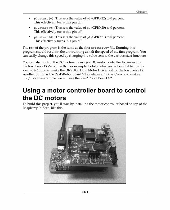
You can also control the DC motors by using a DC motor controller to connect to the Raspberry Pi Zero directly. For example, Pololu, who can be found at https://www.pololu.com/, make the DRV8835 Dual Motor Driver Kit for the Raspberry Pi. Another option is the RasPiRobot Board V2 available at http://www.monkmakes.com/. For this example, we will use the RasPiRobot Board V2.
Using a motor controller board to control the DC motorsTo build this project, you'll start by installing the motor controller board on top of the Raspberry Pi Zero, like this:
Building and Controlling a Simple Wheeled Robot
[ 90 ]
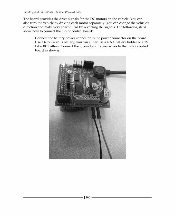
The board provides the drive signals for the DC motors on the vehicle. You can also turn the vehicle by driving each motor separately. You can change the vehicle's direction and make very sharp turns by reversing the signals. The following steps show how to connect the motor control board:
1. Connect the battery power connector to the power connector on the board. Use a 6 to 7.4 volts battery; you can either use a 4 AA battery holder or a 2S LiPo RC battery. Connect the ground and power wires to the motor control board as shown:
Chapter 4
[ 91 ]
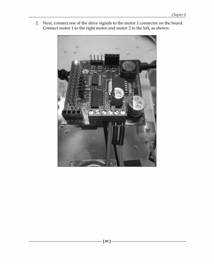
2. Next, connect one of the drive signals to the motor 1 connector on the board. Connect motor 1 to the right motor and motor 2 to the left, as shown:
Building and Controlling a Simple Wheeled Robot
[ 92 ]
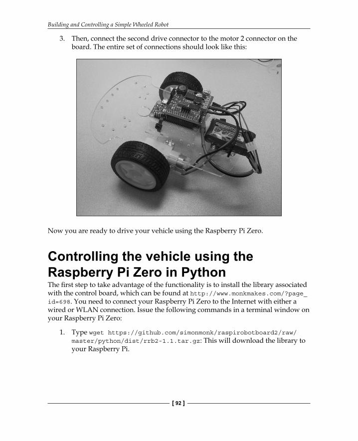
3. Then, connect the second drive connector to the motor 2 connector on the board. The entire set of connections should look like this:
Now you are ready to drive your vehicle using the Raspberry Pi Zero.
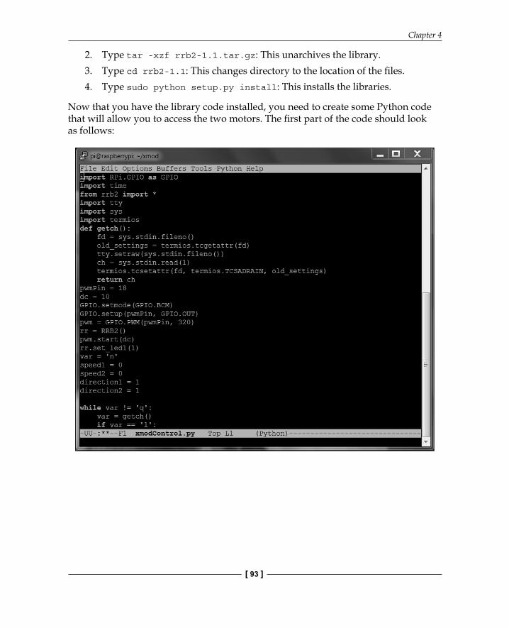
Controlling the vehicle using the Raspberry Pi Zero in PythonThe fi rst step to take advantage of the functionality is to install the library associated with the control board, which can be found at http://www.monkmakes.com/?page_id=698. You need to connect your Raspberry Pi Zero to the Internet with either a wired or WLAN connection. Issue the following commands in a terminal window on your Raspberry Pi Zero:
1. Type wget https://github.com/simonmonk/raspirobotboard2/raw/master/python/dist/rrb2-1.1.tar.gz: This will download the library to your Raspberry Pi.
Chapter 4
[ 93 ]
2. Type tar -xzf rrb2-1.1.tar.gz: This unarchives the library.3. Type cd rrb2-1.1: This changes directory to the location of the fi les.4. Type sudo python setup.py install: This installs the libraries.
Now that you have the library code installed, you need to create some Python code that will allow you to access the two motors. The fi rst part of the code should look as follows:
Building and Controlling a Simple Wheeled Robot
[ 94 ]
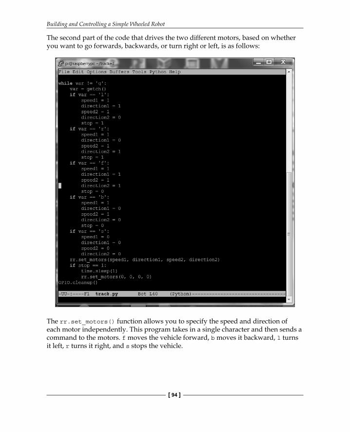
The second part of the code that drives the two different motors, based on whether you want to go forwards, backwards, or turn right or left, is as follows:
The rr.set_motors() function allows you to specify the speed and direction of each motor independently. This program takes in a single character and then sends a command to the motors. f moves the vehicle forward, b moves it backward, l turns it left, r turns it right, and s stops the vehicle.
Chapter 4
[ 95 ]
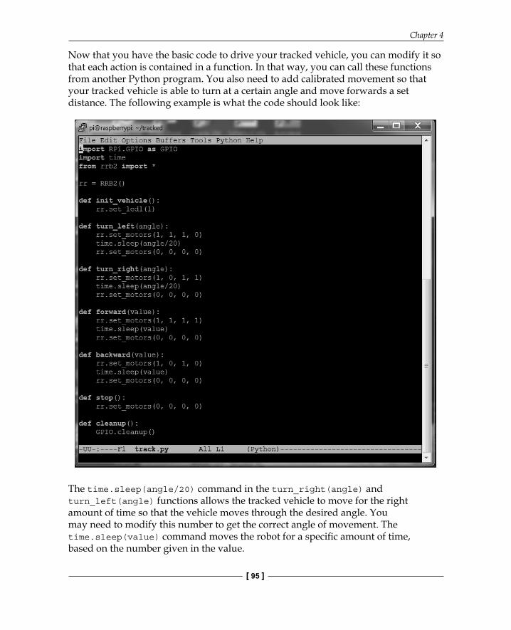
Now that you have the basic code to drive your tracked vehicle, you can modify it so that each action is contained in a function. In that way, you can call these functions from another Python program. You also need to add calibrated movement so that your tracked vehicle is able to turn at a certain angle and move forwards a set distance. The following example is what the code should look like:
The time.sleep(angle/20) command in the turn_right(angle) and turn_left(angle) functions allows the tracked vehicle to move for the right amount of time so that the vehicle moves through the desired angle. You may need to modify this number to get the correct angle of movement. The time.sleep(value) command moves the robot for a specifi c amount of time, based on the number given in the value.
Building and Controlling a Simple Wheeled Robot
[ 96 ]
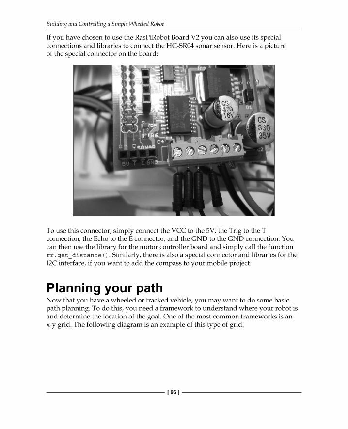
If you have chosen to use the RasPiRobot Board V2 you can also use its special connections and libraries to connect the HC-SR04 sonar sensor. Here is a picture of the special connector on the board:
To use this connector, simply connect the VCC to the 5V, the Trig to the T connection, the Echo to the E connector, and the GND to the GND connection. You can then use the library for the motor controller board and simply call the function rr.get_distance(). Similarly, there is also a special connector and libraries for the I2C interface, if you want to add the compass to your mobile project.
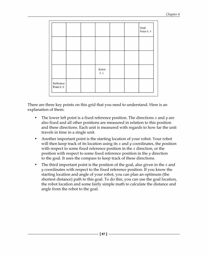
Planning your pathNow that you have a wheeled or tracked vehicle, you may want to do some basic path planning. To do this, you need a framework to understand where your robot is and determine the location of the goal. One of the most common frameworks is an x-y grid. The following diagram is an example of this type of grid:
Chapter 4
[ 97 ]
There are three key points on this grid that you need to understand. Here is an explanation of them:
• The lower left point is a fixed reference position. The directions x and y are also fixed and all other positions are measured in relation to this position and these directions. Each unit is measured with regards to how far the unit travels in time in a single unit.
• Another important point is the starting location of your robot. Your robot will then keep track of its location using its x and y coordinates, the position with respect to some fixed reference position in the x direction, or the position with respect to some fixed reference position in the y direction to the goal. It uses the compass to keep track of these directions.
• The third important point is the position of the goal, also given in the x and y coordinates with respect to the fixed reference position. If you know the starting location and angle of your robot, you can plan an optimum (the shortest distance) path to this goal. To do this, you can use the goal location, the robot location and some fairly simple math to calculate the distance and angle from the robot to the goal.
Building and Controlling a Simple Wheeled Robot
[ 98 ]
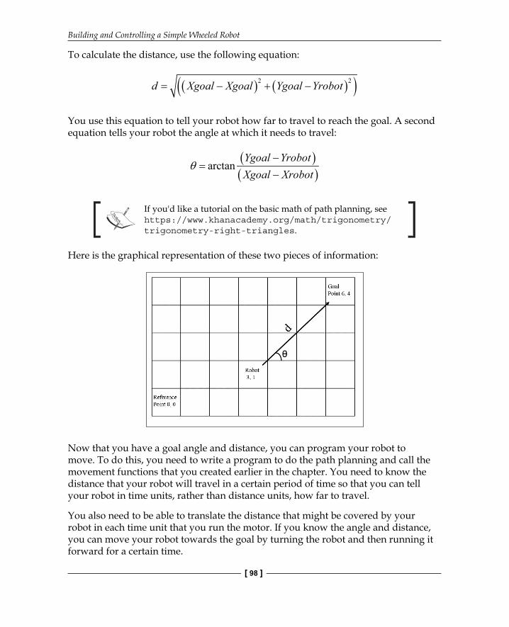
To calculate the distance, use the following equation:
( ) ( )( )2 2d Xgoal Xgoal Ygoal Yrobot= − + −
You use this equation to tell your robot how far to travel to reach the goal. A second equation tells your robot the angle at which it needs to travel:
( )( )
arctanYgoal YrobotXgoal Xrobot
θ−
=−
If you'd like a tutorial on the basic math of path planning, see https://www.khanacademy.org/math/trigonometry/trigonometry-right-triangles.
Here is the graphical representation of these two pieces of information:
Now that you have a goal angle and distance, you can program your robot to move. To do this, you need to write a program to do the path planning and call the movement functions that you created earlier in the chapter. You need to know the distance that your robot will travel in a certain period of time so that you can tell your robot in time units, rather than distance units, how far to travel.
You also need to be able to translate the distance that might be covered by your robot in each time unit that you run the motor. If you know the angle and distance, you can move your robot towards the goal by turning the robot and then running it forward for a certain time.
Chapter 4
[ 99 ]
Here are the steps that you need to follow:
1. Calculate the distance in units that your robot will travel to reach its goal. Convert this into a number of time units to realize this distance.
2. Calculate the angle at which your robot will need to travel to reach its goal. You need to use the compass and your robot's turn functions to turn and achieve this angle.
3. Now, call the step function a specifi ed number of times to move your robot in the correct distance.
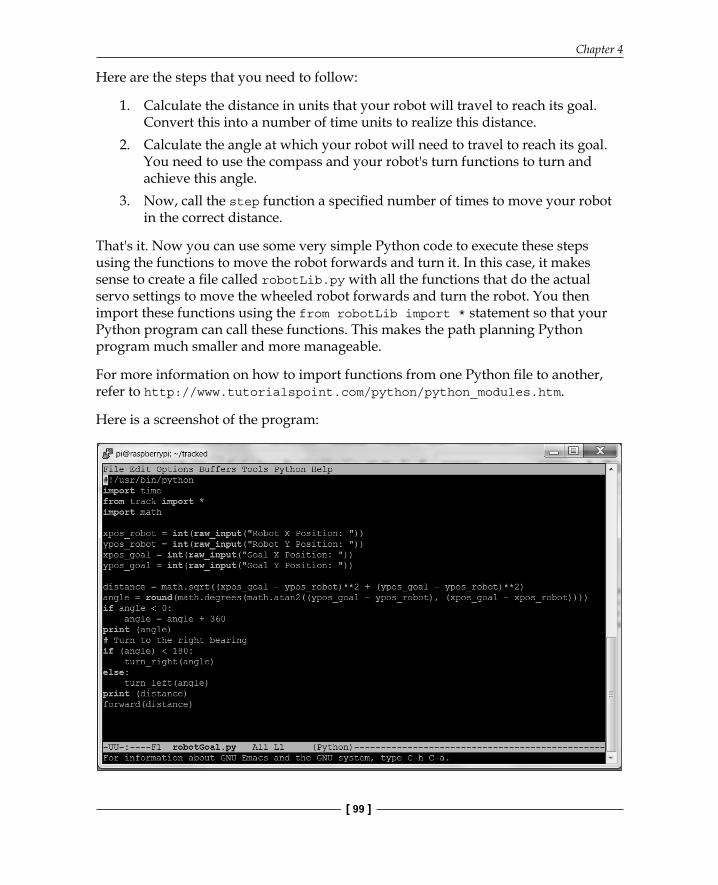
That's it. Now you can use some very simple Python code to execute these steps using the functions to move the robot forwards and turn it. In this case, it makes sense to create a fi le called robotLib.py with all the functions that do the actual servo settings to move the wheeled robot forwards and turn the robot. You then import these functions using the from robotLib import * statement so that your Python program can call these functions. This makes the path planning Python program much smaller and more manageable.
For more information on how to import functions from one Python fi le to another, refer to http://www.tutorialspoint.com/python/python_modules.htm.
Here is a screenshot of the program:
Building and Controlling a Simple Wheeled Robot
[ 100 ]
In this program, the user determines the goal location and the robot decides on the shortest direction to the desired location by reading the angle. To make it simple, the robot is positioned in the grid, heading in the direction of an angle of 0 degrees. If the goal angle were less than 180 degrees, the robot would turn right. If it were greater than 180 degrees, the robot would turn left. The robot turns until the desired angle and the measured angle are within a few degrees of each other. Then, the robot takes the number of steps to reach the goal. As an additional challenge, you could add a loop to measure the actual angle and stop it when it reaches the target angle.
SummaryThis chapter provided you with an opportunity to create a mobile platform for your Raspberry Pi Zero. You can add the sonar sensor or the compass from Chapter 3, Accessing the GPIO Pins on Raspberry Pi Zero to give it even more functionality. In the next chapter, you'll learn how to build a Raspberry Pi Zero platform robot with legs, an even more fl exible mobile platform.
Where to buy this book You can buy Getting Started with Raspberry Pi Zero from the Packt Publishing website.
Alternatively, you can buy the book from Amazon, BN.com, Computer Manuals and most internet
book retailers.
Click here for ordering and shipping details.
www.PacktPub.com
Stay Connected:
Get more information Getting Started with Raspberry Pi Zero