rapid repair and retrofit of timber piles using uhpc
TRANSCRIPT

RAPID REPAIR AND RETROFIT OF TIMBER PILES USING UHPC
Quarterly Progress Report
For the period ending May 31, 2021.
Submitted by: Carlos Sosa, Research Assistant
PI: Islam Mantawy, Ph.D., Research Assistant Professor
Co-PI: Atorod Azizinamini, Ph.D., PE., Director of ABC-UTC
Graduate Student: Carlos Sosa
Affiliation: Department of Civil and Environmental Engineering
Florida International University
Miami, FL
Submitted to:
ABC-UTC
Florida International University
Miami, FL

1. Background and Introduction
Timber piles are often in bridge substructure in rural areas and in coastal touristic piers (such as
Santa Monic Pier) and are subject physical agents (mechanical damage, steel corrosion contact,
etc.) as well as to damage from surrounding water stream or due to biological effects (bacteria,
fungi, insects, etc.). Nowadays preservative as well as retrofitting techniques are applied to old
timber structures for maintenance and repair. For preservation, Creosote, Chromated Copper
Arsenate and other chemical products are available to treat timber and extent durability. For repair
and retrofit concrete/steel jacketing, besides other methods, had been proved effective. The cost of
repairing/retrofitting timber piles would be much cheaper compared to replacing them. The best
repair technique should restore the load-carrying capacity of the timber piles and at the same time
should be cost-effective. In this research, we propose the use of UHPC as repair/retrofit material
for timber piles. Our research approach includes the investigation of bond strength between timber
as substrate material and UHPC as repair material in addition to studying the load-carrying
mechanism of repaired/retrofitted timber piles using UHPC. The proposed research will be
conducted experimentally in two phases: 1) small-scale testing including push-out test to evaluate
the bond strength between timber and UHPC and compressive tests to evaluate the load-carrying
capacity of the repaired timber specimens; 2) large-scale testing where repaired timber piles using
UHPC will be tested under axial and lateral load schemes. Numerical modeling using finite
element models will be conducted on the tested specimens to better understand the behavior of
repaired timber piles using UHPC.
2. Problem Statement
One of bridge substructure system utilizes a pier consists of a beam supported over timber
piles. This substructure system is common practice in county bridges. Many reasons can lead to
the deterioration of these timber piles over an extended period of time such as biological damage
caused by fungi, termites, powderpost beetle, carpenter ants, and bacteria or physical damage due
to floating in water, overload, failure of adjacent piles, and firs. (A. Mohammadi, 2014). Figure 1
shows some possible locations for the damage in timber piles and proposed partial or full UHPC
encasement.
Figure 1. Common damages in timber piles (left) and proposed UHPC repair/retrofit (right).
Replacing the damaged timber pile may be considered an obvious option to address the
damage; however, the cost of an effective repair and retrofitting of timber piles can be much
cheaper. Different repair and retrofit techniques are available for the timber piles and some of the
retrofit options failed to result in the expected performance levels. (J. H. Gull, 2015)
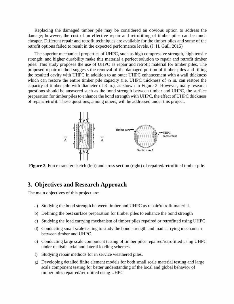
The superior mechanical properties of UHPC, such as high compressive strength, high tensile
strength, and higher durability make this material a perfect solution to repair and retrofit timber
piles. This study proposes the use of UHPC as repair and retrofit material for timber piles. The
proposed repair method suggests the removal of the damaged portion of timber piles and filling
the resulted cavity with UHPC in addition to an outer UHPC enhancement with a wall thickness
which can restore the entire timber pile capacity (i.e. UHPC thickness of ½ in. can restore the
capacity of timber pile with diameter of 8 in.), as shown in Figure 2. However, many research
questions should be answered such as the bond strength between timber and UHPC, the surface
preparation for timber piles to enhance the bond strength with UHPC, the effect of UHPC thickness
of repair/retrofit. These questions, among others, will be addressed under this project.
Figure 2. Force transfer sketch (left) and cross section (right) of repaired/retrofitted timber pile.
3. Objectives and Research Approach
The main objectives of this project are:
a) Studying the bond strength between timber and UHPC as repair/retrofit material.
b) Defining the best surface preparation for timber piles to enhance the bond strength
c) Studying the load carrying mechanism of timber piles repaired or retrofitted using UHPC.
d) Conducting small scale testing to study the bond strength and load carrying mechanism
between timber and UHPC.
e) Conducting large scale component testing of timber piles repaired/retrofitted using UHPC
under realistic axial and lateral loading schemes.
f) Studying repair methods for in service weathered piles.
g) Developing detailed finite element models for both small scale material testing and large
scale component testing for better understanding of the local and global behavior of
timber piles repaired/retrofitted using UHPC.

4. Description of Research Project Tasks
The following is a description of tasks carried out to date.
Task 1 – Conducting literature review on current practice of repair and retrofit of
timber piles
In this task, a comprehensive literature review will be conducted including the current repair
and retrofit practices for timber piles, bond strength between timber piles and repair materials, and
load carrying capacity of repaired/retrofitted timber piles.
Progress: This task is completed. Many reports and publications are collected and studied.
Task 2 – Small scale experimental work
In this task, experimental work will be conducted on small scale level specimens to study the
bond strength of UHPC as repair/retrofit material for timber with different surface preparation. In
addition, compressive tests will be conducted on cylindrical shape timber with UHPC shell to
study the load carrying mechanism between timber piles and UHPC.
Progress: This task is complete. Small scale samples were constructed in the laboratory by shaping
timber into prisms and cylinders.
For bond strength study, timber prisms were cut with a dimension of 4”x4”x8” (width x length
x height) to form a push-off test specimen. The push-off test specimens consist of intermediate
timber prism and outer UHPC prisms with a dimension of 4”x4”x8” (width x length x height) as
shown in Figure 3, the intermediate timber prism was then placed inside timber formwork, as
shown in Figure 4. Different surface preparations were selected to enhance the bond between
timber and UHPC including smooth surfaces, rough surfaces, horizontal nails, inclined nails,
horizontal holes, and inclined holes, as shown in Figure 5 and Figure 6. A total of 14 specimens
were tested under push-off test setup, as shown in Figure 7. Tables 1 and 2 lists the specimen
notations, failure load of each specimen, and the average bond strength of each surface
preparations.
Figure 3. Construction for push-off specimens

Figure 4. Formwork for pull-off specimens prior to casting UHPC.
Figure 5. Schematic for pull-off test specimens different surface preparation between timber
(inner) and UHPC (outer), (a) plain, (b) horizontal nails, (c) horizontal holes, (d) rough surface,
(e) inclined nails and (f) inclined holes.
Figure 6. Different surface preparation for timber prisms
Figure 7. Push-off test setup.
a b c d
e f

Table 1. Specimen notation and description for push-off shear samples.
Specimen notation Description
P Timber’s plain surface
R Timber’s rough surface
H90 Holes in timber perpendicular to bonding surface
H45 Holes in timber inclined 45 degrees to bonding surface
N90 Nails inside timber perpendicular to bonding surface
N45 Nails inside timber inclined 45 degrees to bonding surface
Table 2 Push-off shear test results.
Specimen
notation
Max load
(kip) Stress (psi)
Average per
type
Standard
deviation
H90-1 3.3 53.7
69.3 13.6 H90-2 4.4 75.5
H90-3 4.8 78.7
H-45 2.7 47.1 47.1 -
R-1 3.8 62.5
73.8 16.9 R-2 5.1 93.3
R-3 3.9 65.7
N90-1 9.8 159.3
168.8 8.3 N90-2 9.6 171.7
N90-3 10.1 175.2
N-45 4.5 76.6 76.6 -
P01 0.8 13.9
- - P02 0 0.0*
P03 0 0.0*
For load-carrying capacity, timber cylinders were cut by woodturning as shown in Figure 8,
some of them were cast with an outer UHPC shell and other specimens were just UHPC shells
molded by the use of cylindrical inner cylindrical styrofoams, as shown in Figure 9. Two diameter-
to-thickness ratios between the inner timber cylinder and outer UHPC shell (d/t) of 6 and 2.57
were selected in this test as shown in Figure 9. All the specimens required cylindrical plastic molds
for forming UHPC, as shown in Figure 10. Same surface preparations as bond strength specimens
were replicated in the load-carrying capacity test as shown in Figures 11 and 12. Figure 13 shows
the compression test setup and Figure 14 shows the final damage of one specimen. It should be
noticed that two timber moister preparations were conducted by (1) soaking timber in a water tank
prior to casting UHPC (2) by spraying timber with water prior to casting UHPC. Tables 3 and 4
lists all specimen notations, failure load, and average failure load for each group. New specimens
were cast as shown in Figure 15.
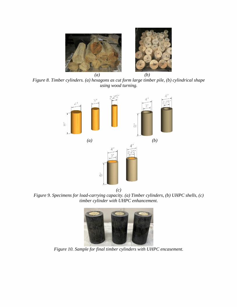
(a) (b)
Figure 8. Timber cylinders. (a) hexagons as cut form large timber pile, (b) cylindrical shape
using wood turning.
(a) (b)
(c)
Figure 9. Specimens for load-carrying capacity. (a) Timber cylinders, (b) UHPC shells, (c)
timber cylinder with UHPC enhancement.
Figure 10. Sample for final timber cylinders with UHPC encasement.

Figure 11. Schematic for load-carrying capacity test specimens different surface preparation
between timber (inner) and UHPC (outer), (a) plain, (b) horizontal nails, (c) horizontal holes,
(d) rough surface, (e) inclined nails and (f) inclined holes.
Figure 12. Different surface preparation for timber prisms
Figure 13. Test setup for load-carrying capacity. (a) timber specimen, (b) timber cylinder with
UHPC encasement.
Figure 14. Failure mode of one of tested specimen.
a b c d
e f

Table 3 Specimen notation and description for small scale compression samples
Notation Level notation Description
Level 1
T Timber only
TC Timber core (reduced section)
V Void due to internal foam in UHPC shell
P Plain (smooth) surface of timber core
R Rough surface of timber core
H Holes at timber´s surface
N Surface with nails
Level 2
4.0
Timber Diameter in inches 3.0
2.25
Level 3
01
Repetitions ID 02
03
Level 4 sk Soaked timber when casting UHPC
sp Sprayed timber when casting UHPC
Table 4 Load-carrying capacity results
Specimen notation Max load (kip) Average per type Standard deviation
T-4.0-01 53
53.0 3.0 T-4.0-02 56
T-4.0-03 50
TC-3.0-01 34
35.3 2.3 TC-3.0-02 38
TC-3.0-03 34
TC-2.25-01 13
14.3 5.1 TC-2.25-02 10
TC-2.25-03 20
V-3.0-01 96
94.7 17.0 V-3.0-02 77
V-3.0-03 111
V-2.25-01 210
200.3 9.5 V-2.25-02 191
V-2.25-03 200
P-3.0-01-sp 68
68.7 8.0 P-3.0-02-sp 77
P-3.0-03-sp 61
P-3.0-01-sk 97
96.0 11.5 P-3.0-02-sk 84
P-3.0-03-sk 107
R-3.0-01-sp 46
50.0 7.8 R-3.0-02-sp 59
R-3.0-03-sp 45
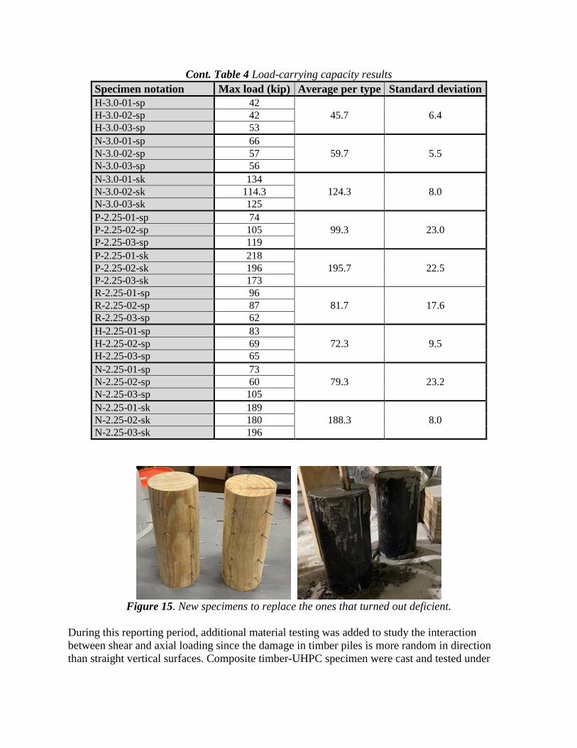
Cont. Table 4 Load-carrying capacity results
Specimen notation Max load (kip) Average per type Standard deviation
H-3.0-01-sp 42
45.7 6.4 H-3.0-02-sp 42
H-3.0-03-sp 53
N-3.0-01-sp 66
59.7 5.5 N-3.0-02-sp 57
N-3.0-03-sp 56
N-3.0-01-sk 134
124.3 8.0 N-3.0-02-sk 114.3
N-3.0-03-sk 125
P-2.25-01-sp 74
99.3 23.0 P-2.25-02-sp 105
P-2.25-03-sp 119
P-2.25-01-sk 218
195.7 22.5 P-2.25-02-sk 196
P-2.25-03-sk 173
R-2.25-01-sp 96
81.7 17.6 R-2.25-02-sp 87
R-2.25-03-sp 62
H-2.25-01-sp 83
72.3 9.5 H-2.25-02-sp 69
H-2.25-03-sp 65
N-2.25-01-sp 73
79.3 23.2 N-2.25-02-sp 60
N-2.25-03-sp 105
N-2.25-01-sk 189
188.3 8.0 N-2.25-02-sk 180
N-2.25-03-sk 196
Figure 15. New specimens to replace the ones that turned out deficient.
During this reporting period, additional material testing was added to study the interaction
between shear and axial loading since the damage in timber piles is more random in direction
than straight vertical surfaces. Composite timber-UHPC specimen were cast and tested under

Slant Shear test setup with different inclinations of 30, 45, 60 degrees as shown in Figure 16.
Table 5 shows summary of the slant shear test.
a) b)
c)
Figure 16. Slant shear test. a) different surface inclination, b) nails crossing the inclined surface
between UHPC and timber, c) specimen prior to testing.
Table 5 Slant shear test results.
Surface
Inclination
Repetition Maximum Axial Load Bond Strength
Value
(kips)
Average
(kips)
SD
(kips)
Value
(psi)
Average
(psi)
SD
(psi)
30 degree
1 29.97
26.72 2.13
1,872
1669.0 133.2 2 26.18 1,635
3 26.70 1,668
4 24.01 1,500
45 degree
1 23.48
22.01 1.44
1,722
1614.0 105.7 2 23.12 1,695
3 19.83 1,454
4 21.60 1,584
60 degree
1 4.18
4.08 0.11
255
249.0 6.70 2 4.18 255
3 3.92 239
4 4.03 246
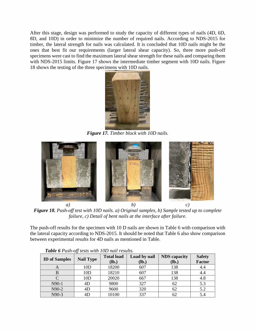
After this stage, design was performed to study the capacity of different types of nails (4D, 6D,
8D, and 10D) in order to minimize the number of required nails. According to NDS-2015 for
timber, the lateral strength for nails was calculated. It is concluded that 10D nails might be the
ones that best fit our requirements (larger lateral shear capacity). So, three more push-off
specimens were cast to find the maximum lateral shear strength for these nails and comparing them
with NDS-2015 limits. Figure 17 shows the intermediate timber segment with 10D nails. Figure
18 shows the testing of the three specimens with 10D nails.
Figure 17. Timber block with 10D nails.
a) b) c)
Figure 18. Push-off test with 10D nails. a) Original samples, b) Sample tested up to complete
failure, c) Detail of bent nails at the interface after failure.
The push-off results for the specimen with 10 D nails are shown in Table 6 with comparison with
the lateral capacity according to NDS-2015. It should be noted that Table 6 also show comparison
between experimental results for 4D nails as mentioned in Table.
Table 6 Push-off tests with 10D nail results.
ID of Samples Nail Type Total load
(lb.)
Load by nail
(lb.)
NDS capacity
(lb.)
Safety
Factor
A 10D 18200 607 138 4.4
B 10D 18210 607 138 4.4
C 10D 20020 667 138 4.8
N90-1 4D 9800 327 62 5.3
N90-2 4D 9600 320 62 5.2
N90-3 4D 10100 337 62 5.4
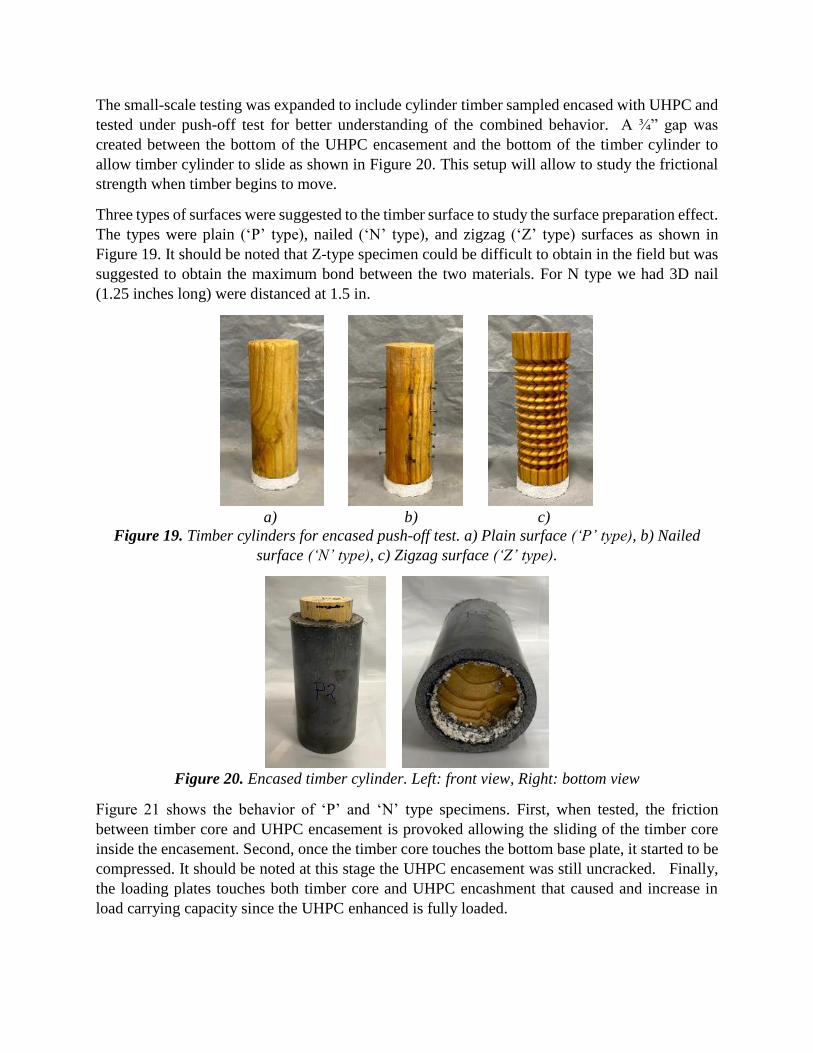
The small-scale testing was expanded to include cylinder timber sampled encased with UHPC and
tested under push-off test for better understanding of the combined behavior. A ¾” gap was
created between the bottom of the UHPC encasement and the bottom of the timber cylinder to
allow timber cylinder to slide as shown in Figure 20. This setup will allow to study the frictional
strength when timber begins to move.
Three types of surfaces were suggested to the timber surface to study the surface preparation effect.
The types were plain (‘P’ type), nailed (‘N’ type), and zigzag (‘Z’ type) surfaces as shown in
Figure 19. It should be noted that Z-type specimen could be difficult to obtain in the field but was
suggested to obtain the maximum bond between the two materials. For N type we had 3D nail
(1.25 inches long) were distanced at 1.5 in.
a) b) c)
Figure 19. Timber cylinders for encased push-off test. a) Plain surface (‘P’ type), b) Nailed
surface (‘N’ type), c) Zigzag surface (‘Z’ type).
Figure 20. Encased timber cylinder. Left: front view, Right: bottom view
Figure 21 shows the behavior of ‘P’ and ‘N’ type specimens. First, when tested, the friction
between timber core and UHPC encasement is provoked allowing the sliding of the timber core
inside the encasement. Second, once the timber core touches the bottom base plate, it started to be
compressed. It should be noted at this stage the UHPC encasement was still uncracked. Finally,
the loading plates touches both timber core and UHPC encashment that caused and increase in
load carrying capacity since the UHPC enhanced is fully loaded.

Figure 21. Behavior for types plain and nailed surfaces in timber.
Figure 22 shows the behavior of ‘Z’ type specimens. For this case, the timber core never slipped
through the UHPC encasement due to the high friction between timber core and UHPC encasement
which was induced by the corrugated surface preparation. Instead, the timber core was compressed
completely until the loading plate touched the top surface of UHPC encasement and started to be
loaded. Even though, this surface preparation is hard to be obtained for in-service timber, it may
be a good idea in new timber piles that may require UHPC protection for aggressive environment.
Figure 22. Behavior for zigzag type surfaces in timber.
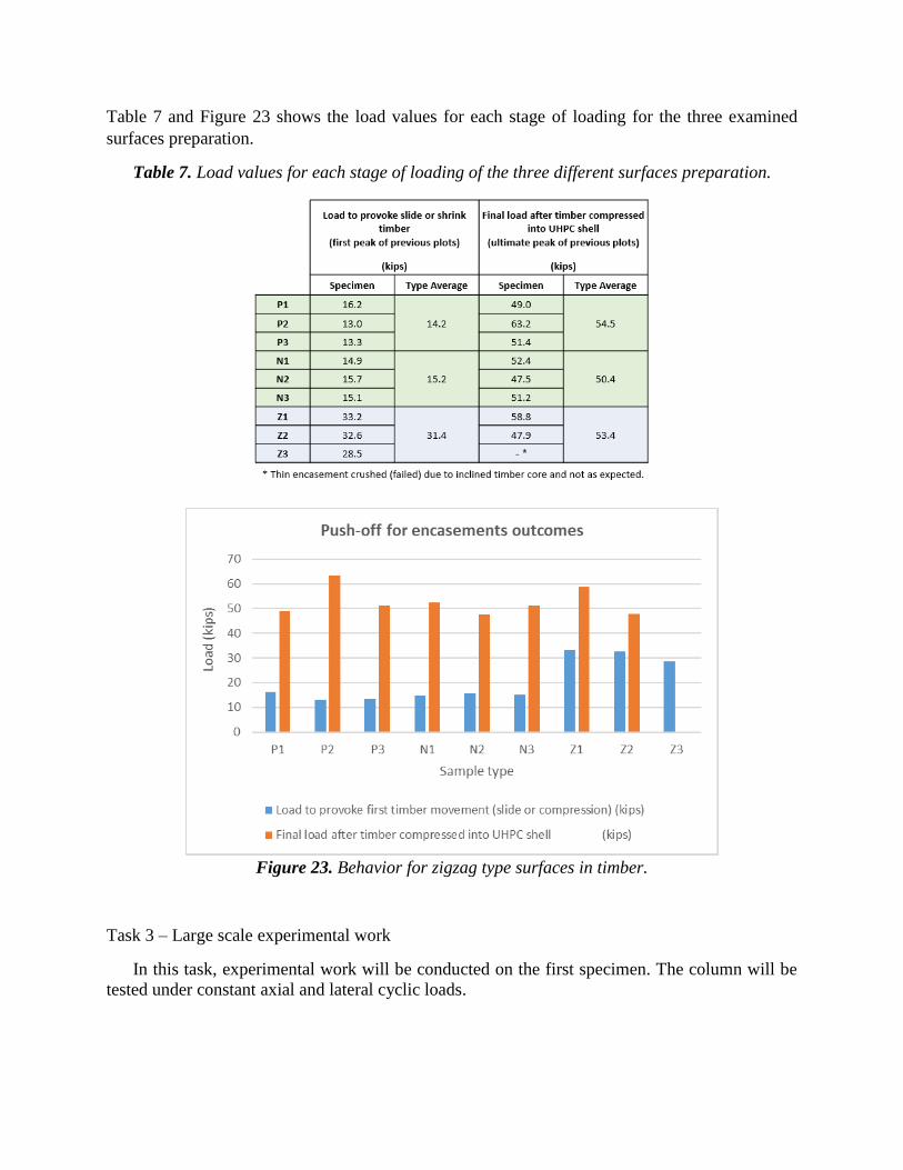
Table 7 and Figure 23 shows the load values for each stage of loading for the three examined
surfaces preparation.
Table 7. Load values for each stage of loading of the three different surfaces preparation.
Figure 23. Behavior for zigzag type surfaces in timber.
Task 3 – Large scale experimental work
In this task, experimental work will be conducted on the first specimen. The column will be
tested under constant axial and lateral cyclic loads.

Progress: Researchers completed the design of the specimens for full-scale testing based on the
results and findings from small-scale testing. Schematic illustration of the tested specimens is show
in Figure 24. Construction of the specimens will start summer 2021.
Figure 24. Test setup for large-scale specimens
Task 4 – Numerical model verification through finite element analysis
In this task, numerical models will be developed to calibrate the test results from Task 2 and
Task 3 to better understand.
Progress: Using the results from small-scale tests numerical models are being prepared using
ATENA software as shown in Figure 25.
Figure 25. Numerical model of push-off tests using ATENA software.
Task 5 – Final Report
In this task, full assessment of the findings from Task 1 throughout Task 4 will be conducted
and a report will be published including design recommendations of repairing and retrofitting
timber piles using UHPC.
Progress: Researchers are building up this report for the final report.

5. Expected Deliverables
The final report, journal articles, design guidelines, and a five-minute video presentation will
be the expected deliverables.
6. Schedule
Item % Completed
Percentage of Completion of this project to Date 65%
7. Reference
J. H. Gull, A. Mohammadi, R. Taghinezhad, and A. Azizinamini, “Experimental evaluation of
repair options for timber piles,” Transp. Res. Rec., 2015.
A. Mohammadi, P. D. Jawad H. Gull, R. Taghinezhad, and P. D. P. E. Atorod Azizinamini,
“Assessment and Evaluation of Timber Piles Used in Nebraska for Retrofit and Rating,”
2014.
Timber Piling Council, and American Wood Preservers Institute, “Timber Pile Design and
Construction Manual” 2002.
J F M A M J J A S O N D J F M A M J
Task 5–Final Report
Proposed
Completed
Research Task 20212020
Task 1 – Conducting literature review on current practice of repair
and retrofit of timber piles
Task 2– Small scale experimental work
Task 3– Large scale experimental work
Task 4 – Numerical model verification through finite element
analysis