alternativeabc connections using uhpc€¦ · alternativeabc connections using uhpc by mohamadreza...
TRANSCRIPT

Alternative ABC Connections UsingUHPC
ByMohamadreza Shafieifar, Ph.D Candidate
Atorod Azizinamini, Ph.D., P.E., Director, ABC-UTC and Chair, CEE Dept., FIU
Florida International UniversityApril 2018

2
Major Categories of UHPC Investigations
1- UHPC based connections to connect prefabricated elements2- UHPC based solutions for repairing and upgrading bridge columns3- UHPC based solutions for repairing and upgrading beams and deck4- ABC made conventional

UHPC Based Technologies for Upgrading and Retrofitting Existing Bridges- Columns
3
Major Categories of UHPC Investigations

UHPC Based Technologies for Upgrading and Retrofitting Existing Bridges- Columns
4
Major Categories of UHPC Investigations

UHPC Based Technologies for Upgrading and Retrofitting Existing Bridges- Columns
Mahsa FarzadPh.D Candidate
Amir SadeghjejadPh.D Candidate
5
Major Categories of UHPC Investigations

UHPC Based Technologies for Upgrading and Retrofitting Existing Bridges- Beams and deck
6
Major Categories of UHPC Investigations

UHPC Based Technologies for Upgrading and Retrofitting Existing Bridges- Beams and deck
7
Major Categories of UHPC Investigations

UHPC Based Technologies for Upgrading and Retrofitting Existing Bridges- Beams and deck
Alireza ValikhaniPh.D Candidate
8
Major Categories of UHPC Investigations

ABC Made ConventionalThrough UHPC Shell
9

This major research activity involves cluster of research studies consisting of constructing outside profile of every member of the bridge, using UHPC, transporting them to final bridge site, connecting them together and filling them with concrete
10
Major Categories of UHPC Investigations

11

12

13

14

15

16

17

18

19

20

21

22

Investigation includesBeamsColumnsFoundationConnectionsSeismic and Non-seismic
23

Advantages
1- Eliminates the need for form work2- Eliminates the need for removal of formwork3- UHPC protects the concrete inside- Maintenance free4- Light weight concrete could be used to fill the cavity 5- Use of light weight concrete reduces foundation sizes6- It increases the member capacity using same dimension7- Allows using smaller cross section8- Reinforcement could be incorporated into the shell, reducing field operations9- Uses conventional methods of construction 24
ABC Made Conventional

Rozita MazaherimeybodiPh.D Student
Sheharayar-e-RehmatPh.D Candidate
25
ABC Made Conventional

UHPC Based ABC Connections for connecting precast columns
to precast cap beamMohamadreza ShafieifarPh.D CandidateFlorida International University

Problem StatementCurrently all ABC Connections used in practice, to connect cap beam, to columns, uses types of connections where steel reinforcement penetrates into the cap beam, creating a very congested and challenging detailing Requirements within the cap beam.
27

Background -Common ConnectionsBar Couplers
28

Background Common ConnectionsGrouted Ducts
Pics Ref: NCHRP report 681
29

Background Common ConnectionsPocket Connections
Pics Ref: NCHRP report 68130

Prefabricate Element (As one Part)
Cap beam
UHPC
Plastic Hinge Region
Proposed Connection Detail
Detail 1
Prefabricate Column
Splice Region
Prefabricate Element
UHPC

Prefabricate Cap beam
Proposed Connection Detail
Detail 2 32
Prefabricate Column
Splice Region
Cap Beam
UHPC

Proposed Connection Details
Detail 1 Detail 233

Advantages✓Large Tolerances
✓Developing the reinforcement over short length
Splice region using UHPC
34

Advantages✓Eliminating the potential interferences with reinforcement in the
cap beam✓Eliminating need for stirrups
35

Overview of Experimental Investigation
36
Feasibility study – Large scale column test20 by 20 inch square cross section
First test series– Four circular columns12 inch in diameter
Second test series– Six circular columns12 inch in diameter

Cap Beam(Normal Strength Concrete)
Plastic Hinge(Normal Strength Concrete)Splice region
using UHPC
Column
UHPC
Feasibility Study – Tested a large scale specimen
37

Construction of the SpecimenSegment Representing Prefabricated segment
Regular Concrete
Regular Concrete
38

Construction of the SpecimenConnecting precast column to precast cap beam
39
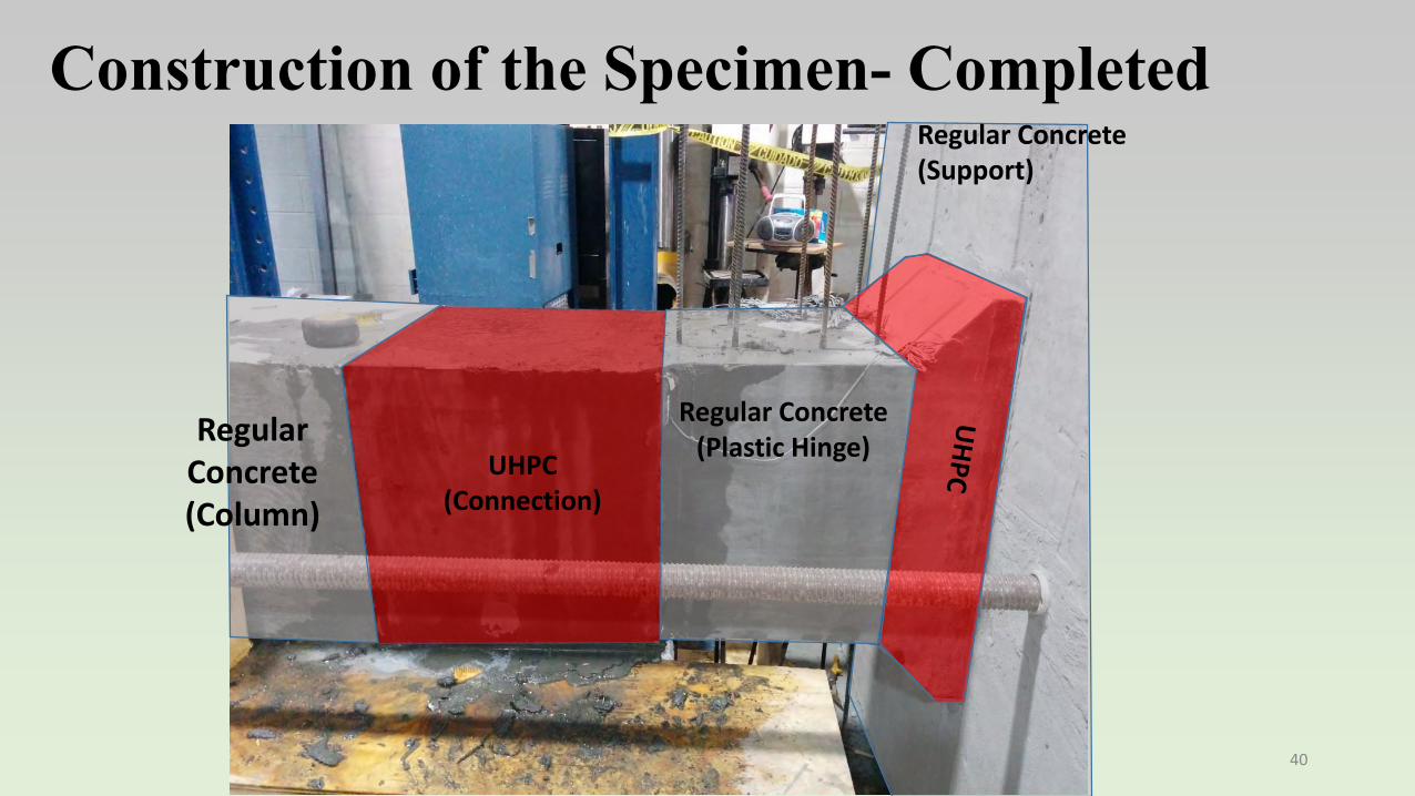
Construction of the Specimen- CompletedRegular Concrete(Support)
Regular Concrete(Plastic Hinge)
UHPC(Connection)
Regular Concrete(Column)
40

Test Setup and Testing proceduresLoading and Supports (Axial Load=200 Kip (10% Pu)
41

Specimen at test conclusion5 Δ y 5 Δ y
Cap
Bea
m (R
.C)
Plas
tic H
inge
(R
.C)
Col
umn
(R.C
)
UH
PC
Splic
e R
egio
n U
HPC
42

Specimen at test conclusion
Bottom Top
43

Results - Moment-Displacement
-10000
-8000
-6000
-4000
-2000
0
2000
4000
6000
8000
10000
-10 -5 0 5 10
Mom
ent (
Kip
.in)
Displacement (in)
Push Down
Push Up
Push Down
Push Up
44

Results of Numerical Analysis
45

Results of Numerical AnalysisYielding and Crack Formation
46
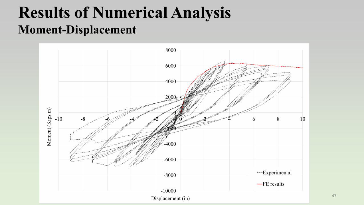
Results of Numerical AnalysisMoment-Displacement
-10000
-8000
-6000
-4000
-2000
0
2000
4000
6000
8000
-10 -8 -6 -4 -2 0 2 4 6 8 10
Mom
ent (
Kip
s.in)
Displacement (in)
Experimental
FE results
47

Second test specimens series (total of 4)Dimension (Parametric Study)
Detail 1 Detail 2 48

Details of the Specimens
• Longitudinal Rebar Size: #5 • Reinforcement Ratio: 2.1%• Transverse Rebar Size: #3 • Column Length/Diameter: 5• Rebar Cover: 1.5 in. 49
1 2 3 4

UHPC
UHPC
UHPC
Second test series – Two details tested
Detail 2 Detail 1
50

Construction of second test specimen series
During casting of second testspecimen series, because of usingmore superplasticizers than needed,steel fibers in the UHPC regions didnot achieve uniform distribution.However, as it will be discussed, thetest outcome was not significantlyaffected.Also because of the shifting therebar cage, concrete cover was notthe same for all side of thespecimens and some of them werenot perfectly symmetric.
UHPC
UHPC
UHPC
Detail 2 Detail 151

Test Setup and Testing ProceduresConstant axial load and cyclic lateral loads
Axial Load
Lateral Load
52

Specimen 1 Stirrups spacing in plastic region 2.5 inchesStirrups spacing in splice region 2.5 inchesAxial load level- 10% (56 Kips)
1Δy 2Δy 3Δy 4Δy
5Δy 6Δy 7Δy 8Δy
53

Specimen ID
Maximum drift
Displacement ductility
S-2.5-2.5-10 8.5 % 7
Specimen 1 Stirrups spacing in plastic region 2.5 inchesStirrups spacing in splice region 2.5 inchesAxial load level- 10% (56 Kips)
54
-2000
-1500
-1000
-500
0
500
1000
1500
2000
-6 -4 -2 0 2 4 6
Mom
ent (
Kip
s.in)
Displacement (in.)

1Δy 2Δy 3Δy 4Δy 5Δy 6Δy
Specimen 2 Stirrups spacing in plastic region 4 inchesNo stirrups spacing in splice regionAxial load level- 10% (56 Kips)
55

Specimen ID
Maximum drift
Displacement ductility
S-4-0-10 5.3 % 5
Specimen 2 Stirrups spacing in plastic region 4 inchesNo stirrups spacing in splice regionAxial load level- 10% (56 Kips)
56
-2000
-1500
-1000
-500
0
500
1000
1500
2000
-6 -4 -2 0 2 4 6
Mom
ent (
kips
.in)
Displacement (in.)

1Δy 2Δy 3Δy 4Δy 5Δy 6Δy
Specimen 3Stirrups spacing in plastic region 2.5 inchesStirrups spacing in splice region 4 inchesAxial load level- 20% (112 Kips)
57
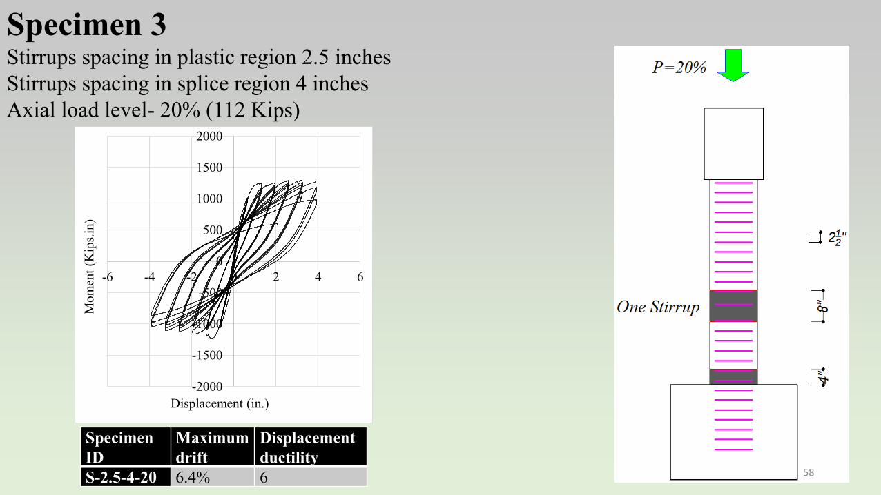
Specimen ID
Maximum drift
Displacement ductility
S-2.5-4-20 6.4% 6
Specimen 3Stirrups spacing in plastic region 2.5 inchesStirrups spacing in splice region 4 inchesAxial load level- 20% (112 Kips)
58
-2000
-1500
-1000
-500
0
500
1000
1500
2000
-6 -4 -2 0 2 4 6
Mom
ent (
Kip
s.in)
Displacement (in.)

1Δy 2Δy 3Δy 4Δy 5Δy
Specimen 4 Stirrups spacing in plastic region 2.5 inchesNo stirrups spacing in splice regionAxial load level- 10% (56 Kips)
59

Specimen ID
Maximum drift
Displacement ductility
NS-2.5-0-10 6.5% 5
Specimen 4 Stirrups spacing in plastic region 2.5 inchesNo stirrups spacing in splice regionAxial load level- 10% (56 Kips)
60
-2000
-1500
-1000
-500
0
500
1000
1500
2000
-6 -4 -2 0 2 4 6
Mom
ent (
Kip
s.in.
)
Displacement (in.)

Results
61
-2000
-1500
-1000
-500
0
500
1000
1500
2000
-6 -4 -2 0 2 4 6
Mom
ent (
Kip
s.in)
Displacement (in.)-2000
-1500
-1000
-500
0
500
1000
1500
2000
-6 -4 -2 0 2 4 6
Mom
ent (
kips
.in)
Displacement (in.)
-2000
-1500
-1000
-500
0
500
1000
1500
2000
-6 -4 -2 0 2 4 6
Mom
ent (
Kip
s.in)
Displacement (in.) -2000
-1500
-1000
-500
0
500
1000
1500
2000
-6 -4 -2 0 2 4 6M
omen
t (K
ips.i
n.)
Displacement (in.)
Specimen 1 Specimen 2
Specimen 3 Specimen 4

Numerical Analysis
Detail 1 Detail 262

Numerical Analysis
63

Conclusion • Both Details 1 and 2 demonstrated ductile behavior and plastic
hinge formed at the desired locations• Both details could be used in seismic regions• Detail 1 allows to precisely define the location of plastic hinge in
the seismic application
Detail 2 Detail 164

Tests Specimens Ready for Testing (6 more Specimens)
65
2 Reference specimens + 4 Detail 2 SpecimensRebar Size #5 & #6 Splice length: 8 db & 12 db Rebar Cover ≈ 2 db

Tests Specimens Ready for Testing (6 more Specimens)
66
No stirrup at splice regionStirrups space in the column: 2.5 in.
1 2 3
#5, Ref #5, 12db #5, 8db

Tests Specimens Ready for Testing (6 more Specimens)
67
No stirrup at splice regionStirrups space in the column: 2.5 in.
4 5 6
#6, Ref #6, 12db #6, 8db

Specimens Ready for Testing(6 More Specimens)
68

69
Summary
- Major research studies are being conducted to develop UHPC based solution to facilitate use of ABC
- ABC made conventional is an overarching cluster of research studies that allows contractors to use conventional construction techniques and reduce onsite construction activities
- We are interested in working with contractors who are interested in “ABC Made Conventional” products and technologies. Please contact us as [email protected]
70
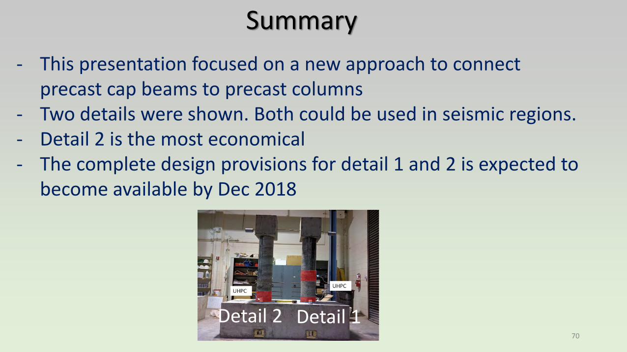
Summary
- This presentation focused on a new approach to connect precast cap beams to precast columns
- Two details were shown. Both could be used in seismic regions.- Detail 2 is the most economical- The complete design provisions for detail 1 and 2 is expected to
become available by Dec 2018
Detail 2 Detail 1

71
SummaryPlease send an email to [email protected] if you need more information or would like to collaborate with us