rao engineering enterprises - reliance · pdf filerao engineering enterprises geotechnical...
TRANSCRIPT

GEOTECHNICAL INVESTIGATION
REPORT
PROJECT
REPORT ON SOIL INVESTIGATION WORK FOR PROPOSED 66KV GRID,
FATEHPUR BERI, DELHI
SUBMITTED BY
RAO ENGINEERING ENTERPRISES GEOTECHNICAL CONSULTANTS & LAND SURVEYORS
91-D-3, STREET NO.1, EAST MOTI BAGH , OLD ROHTAK ROAD, DELHI-110007. PHONES: 011-23698806, Mob. 09310502435, 09310402435, 09811108174, TeleFax-23691434
e-mail : [email protected],[email protected]
PROJECT : REPORT ON SOIL INVESTIGATION WORK FOR 66KV GRID,
FATEHPUR BERI, DELHI. CLIENT : BSES RAJDHANI POWER LIMITED.
1-FLOOR, C-BLOCK, BSES BHAWAN, NEHRU PLACE, DELHI.
REPORT NO. : 7061 DATE : 30.06.2015

RAO ENGINEERING ENTERPRISES - - - GEOTECHNICAL REPORT
REPORT ON SOIL INVESTIGATION WORK FOR 66KV GRID, FATEHPUR BERI, DELHI.
C O N T E N T S
PAGE NO.
1.0 INTRODUCTION 1 1.1 PROJECT DESCRIPTION 1 1.2 AIM OF SOIL INVESTIGATION 1 1.3 SCOPE OF WORK 2 2.0 INVESTIGATIONS CONDUCTED 3 2.1 INSITU TESTS 3 2.1.1 BOREHOLES PROCEDURE 3 2.1.1.1 WATER TABLE 4 2.1.1.2 STANDARD PENETRATION TEST RESULTS 4 2.1.2 ELECTRICAL RESISTIVITY TEST PROCEDURE 5 2.2 LABORATORY TESTS AND RESULTS 6-14 3.0 OBSERVATIONS 15 4.0 DISCUSSIONS 15 4.1 TYPE & DEPTH OF FOUNDATION 16 4.2 ALLOWABLE BEARING PRESSURE 16 5.0 RECOMMENDATIONS 17 5.1 OPEN/RAFT FOUNDATIONS 17 5.2 PILE FOUNDATIONS 17-18 6.0 INTERPRETATION OF ERT 18-19 7.0 CHEMICAL RESULTS 19 8.0 CLOSURE 20 ------ FIGURES 1-17
*****************************

RAO ENGINEERING ENTERPRISES -- GEOTECHNICAL REPORT -- PAGE 1
1.0 INTRODUCTION
1.1 PROJECT DESCRIPTION
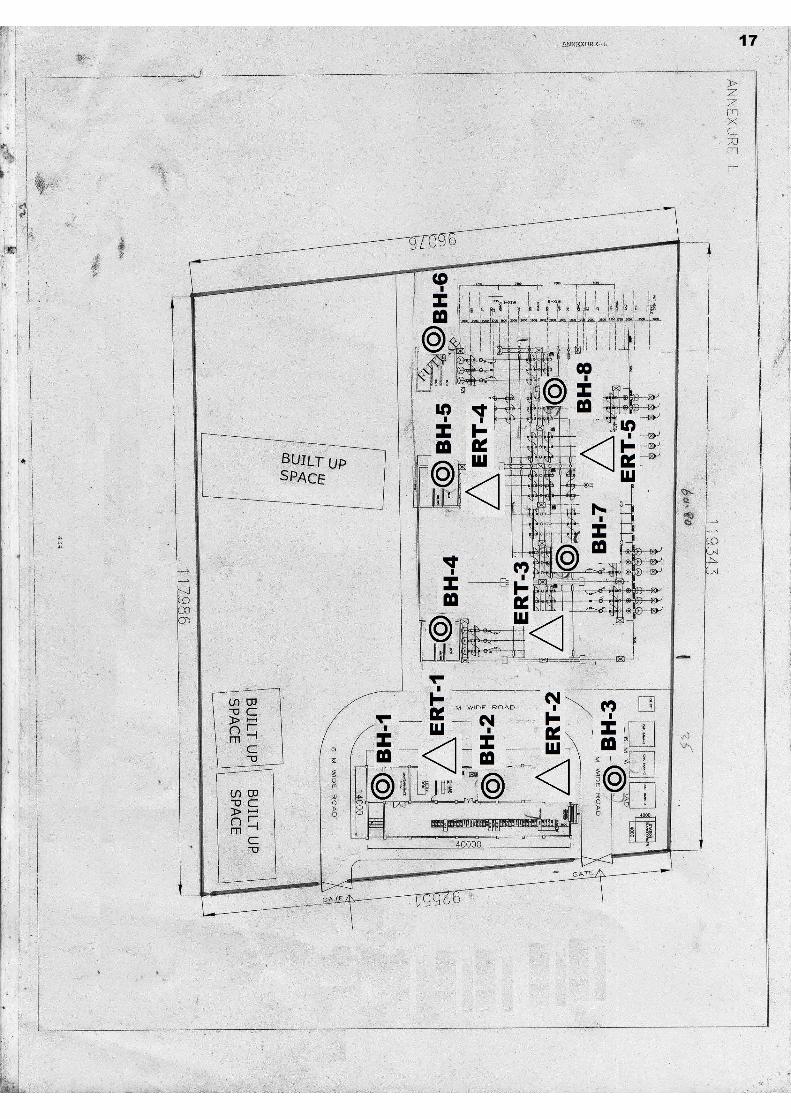
This soil investigation work, whose results are being presented herewith, has been carried out for 66 KV grid, Fatehpur Beri, Delhi. A layout plan showing the locations of our field investigation is illustrated in our report.
1.2 AIM OF SOIL INVESTIGATION
Soil investigation has been conducted at the site in order to evaluate the parameters required for design of foundations. These parameters are :
(a) Type of foundation on which the
proposed super structure will be supported.
(b) Depth of foundation , and (c) Allowable bearing pressure at the
founding level.

RAO ENGINEERING ENTERPRISES -- GEOTECHNICAL REPORT -- PAGE 2
To evaluate these parameters , following engineering properties of the sub - soil have been studied :
(a) Sub-soil Penetration Resistance characteristics
which have been determined insitu. (b) Properties like particle size distribution,
Atterberg limits, bulk density, specific gravity, moisture content, and shear strength parameters; which have been determined in the laboratory by conducting testing of both disturbed as well as undisturbed samples.
1.3 SCOPE OF WORK
The stipulated scope of work comprised of the following : 1. Mobilization of equipment and personnel to the
site and back. 2. Sinking 8 boreholes to 10.0m depth or refusal
whichever is encountered earlier, observing ground water table levels, conducting required field and laboratory tests and their analysis.
3. Conducting 5 Nos. Electrical Resistivity Tests at
the site. 4. Preparation and submission of technical report in
triplicate.

RAO ENGINEERING ENTERPRISES -- GEOTECHNICAL REPORT -- PAGE 3 2.0 INVESTIGATIONS CONDUCTED 2.1 INSITU TESTS
Locations of field-testing points have been marked at the site as per the direction of the client. These locations have been designated as BH-1 to BH-8, ERT-1 to ERT-5 in this report.
2.1.1 BOREHOLES PROCEDURE
The boreholes were progressed to the specified depth of 10.0m.The diameter of the borehole was 150mm. Where caving of the boreholes occurred, casing was used to keep the borehole stable. The work was in general accordance with IS:1892-1979. Standard Penetration Tests (SPT) were conducted in the borehole at 1.5-3.0m interval by connecting a split spoon sampler to ‘A’ rods and driving it by 45 cm using a 63.5 kg hammer falling freely from a height of 75 cm. The tests were conducted in accordance with IS:2131-1981.
The number of blows for each 15 cm of penetration was recorded. The blows required to penetrate the initial 15 cm of the split spoon for seating the sampler is ignored due to the possible presence of loose materials or cuttings from the drilling operation. The cumulative number of blows required to penetrate the balance 30 cm of the 45 cm sampling interval is termed the SPT value or the ‘N’ value.
Disturbed samples were collected from the split spoon after conducting SPT. The samples were preserved in transparent polythene bags. Undisturbed samples were collected by attaching a 100 mm diameter thin walled ‘Shelby’ tubes and driving the sampler lightly using a 63.5 kg hammer in accordance with IS:2132 .

RAO ENGINEERING ENTERPRISES -- GEOTECHNICAL REPORT -- PAGE 4 2.1.1.1 WATER TABLE
In the boreholes, groundwater was encountered at about 6.50-6.80m depth below ground surface during the time of our field investigation (April, 2015). Fluctuations may occur in measured water table due to variation in rainfall and surface evaporation rates.
2.1.1.2 STANDARD PENETRATION TEST RESULTS
Following Standard Penetration Resistance (‘N’) values have been recorded at various depths in the eight boreholes.
DEPTH(M) ‘N’ VALUES - - - - - - - - - - - - - - - - - - - - - - - BH1 BH2 BH3 BH4 - - - - - - - - - - - - - - - - - - - - - - - 1.5 11 14 10 22 3.0 13 16 3 18 4.5 15 22 2 21 6.0 18 25 18 30 7.5 20 30 20 35 9.0 24 34 24 22 10.0 28 39 33 28 --------------------------------------------- DEPTH(M) ‘N’ VALUES - - - - - - - - - - - - - - - - - - - - - - - BH5 BH6 BH7 BH8 - - - - - - - - - - - - - - - - - - - - - - - 1.5 12 14 18 20 3.0 21 18 23 19 4.5 28 23 27 31 6.0 25 39 40 33 7.5 29 27 48 31 9.0 33 35 37 41 10.0 39 49 39 45 ---------------------------------------------

RAO ENGINEERING ENTERPRISES -- GEOTECHNICAL REPORT -- PAGE 5
2.1.2 ELECTRICAL RESISTIVITY TEST PROCEDURE
Electrical resistivity of the soil at the site was determined at the locations specified by the client. The earth resistivity test is used for shallow subsurface exploration by means of electrical measures made at the ground surface. Resistivity measurements are made by driving four electrodes about 10 to 15 cm into the ground at a pre-selected electrode spacing.
The four electrodes were spaced at equal distance along different locations. The average of the resistivity values for each direction was taken as the mean resistivity for that spacing. The test procedure is in accordance with IS:3043:1987. Measurements are made by causing a current, I, to pass through the earth and distribute within a relatively large hemispherical earth mass. The portion of the current that flows along the surface produces a voltage drop, V.
The resistance “R” is the ratio of voltage drop ‘V’ to current I is directly measured by digital earth resistance tester. The resistivity is determined from the following equation - = 2 a R where : = apparent resistivity, ohm-m. a = spacing between the electrodes, metres
R = Resistance, ohms.

RAO ENGINEERING ENTERPRISES -- GEOTECHNICAL REPORT -- PAGE 6
2.2 LABORATORY TESTS AND RESULTS
Following tests have been conducted on various soil and water samples in the laboratory:
Laboratory Test IS : Code Referred
Natural moisture content IS : 2720 (Part-2)-1973
Grain size analysis IS : 2720 (Part-4)-1985
Liquid & Plastic limit IS : 2720 (Part-5)-1985
Unconsolidated Undrained Triaxial shear test
IS : 2720 (Part-11)-1993
Consolidated Drained Direct Shear Test IS : 2720 (Part-13)-1986
Unconfined Compression Test IS : 2720 (Part-10)-1991
Specific Gravity Test IS : 2720 (Part-3)-1980
Determination of pH value IS : 2720 (Part-26)-1987
Chemical Analysis of soil
Determination of total soluble sulphate
IS : 2720 (Part-27)-1977
Determination of total soluble sulphate
IS : 3025 (Part-11)-1996
Determination of chloride content IS : 3025 (Part-24)-1998
Chemical Analysis of water
Determination of pH value IS : 3025 (Part-32)-1993
Results are being tabulated as follows :

RAO ENGINEERING ENTERPRISES -- GEOTECHNICAL REPORT -- PAGE 7
LABORATORY TEST RESULTS
BOREHOLE LOCATION : 1
DISTURBED SAMPLES
DEPTH GRADATION ANALYSIS (%) ATTERBERG LIMITS(%) SP.GR (M) GRAVELS SAND SILT CLAY LIQUID PLASTIC ------------------------------------------------------------ 2.25 8 29 53 10 28.1 18.2 2.70 6.00 0 24 63 13 28.6 18.5 2.72 10.00 0 35 56 9 27.8 17.9 2.69 ------------------------------------------------------------
UNDISTURBED SAMPLES
DEPTH BULK DENSITY WATER DRY COHESION ANGLE OF BELOW (gms/cc) CONTENT DENSITY SHEARING G.L. (%) (gms/cc) (kg/sq.cm) RESISTANCE (M) (Ø) -------------------------------------------------------------- 2.25 1.74 10.2 1.58 0.59 5O
8.25 1.98 15.3 1.72 0.96 8O
--------------------------------------------------------------

RAO ENGINEERING ENTERPRISES -- GEOTECHNICAL REPORT -- PAGE 8
LABORATORY TEST RESULTS
BOREHOLE LOCATION : 2
DISTURBED SAMPLES
DEPTH GRADATION ANALYSIS (%) ATTERBERG LIMITS(%) SP.GR (M) GRAVELS SAND SILT CLAY LIQUID PLASTIC ------------------------------------------------------------ 2.25 0 25 64 11 28.4 18.3 2.71 7.50 0 34 56 10 27.9 18.0 2.70 10.00 2 31 58 9 27.7 17.7 2.70 ------------------------------------------------------------
UNDISTURBED SAMPLES
DEPTH BULK DENSITY WATER DRY COHESION ANGLE OF BELOW (gms/cc) CONTENT DENSITY SHEARING G.L. (%) (gms/cc) (kg/sq.cm) RESISTANCE (M) (Ø) ------------------------------------------------------------ 2.25 1.77 10.1 1.61 0.66 6O
5.25 1.87 12.1 1.67 0.92 7O
------------------------------------------------------------

RAO ENGINEERING ENTERPRISES -- GEOTECHNICAL REPORT -- PAGE 9
LABORATORY TEST RESULTS
BOREHOLE LOCATION : 3
DISTURBED SAMPLES
DEPTH GRADATION ANALYSIS (%) ATTERBERG LIMITS(%) SP.GR (M) GRAVELS SAND SILT CLAY LIQUID PLASTIC ------------------------------------------------------------ 4.50 0 40 47 13 30.8 20.6 2.69 6.00 3 28 58 11 28.3 18.2 2.70 9.00 0 25 63 12 28.6 18.5 2.72 ------------------------------------------------------------
UNDISTURBED SAMPLES
DEPTH BULK DENSITY WATER DRY COHESION ANGLE OF BELOW (gms/cc) CONTENT DENSITY SHEARING G.L. (%) (gms/cc) (kg/sq.cm) RESISTANCE (M) (Ø) ------------------------------------------------------------ 5.25 1.70 12.5 1.51 0.76 7 8.25 1.98 16.2 1.70 1.01 8O
------------------------------------------------------------

RAO ENGINEERING ENTERPRISES -- GEOTECHNICAL REPORT -- PAGE 10
LABORATORY TEST RESULTS
BOREHOLE LOCATION : 4
DISTURBED SAMPLES
DEPTH GRADATION ANALYSIS (%) ATTERBERG LIMITS(%) SP.GR (M) GRAVELS SAND SILT CLAY LIQUID PLASTIC ------------------------------------------------------------ 1.50 0 27 62 11 28.2 18.0 2.70 5.25 5 32 51 12 28.5 18.3 2.71 9.00 2 35 54 9 27.8 17.8 2.69 ------------------------------------------------------------
UNDISTURBED SAMPLES
DEPTH BULK DENSITY WATER DRY COHESION ANGLE OF BELOW (gms/cc) CONTENT DENSITY SHEARING G.L. (%) (gms/cc) (kg/sq.cm) RESISTANCE (M) (Ø) ------------------------------------------------------------ 5.25 1.85 12.4 1.65 0.65 6O
8.25 2.01 15.9 1.73 1.06 7O
------------------------------------------------------------

RAO ENGINEERING ENTERPRISES -- GEOTECHNICAL REPORT -- PAGE 11
LABORATORY TEST RESULTS
BOREHOLE LOCATION : 5
DISTURBED SAMPLES
DEPTH GRADATION ANALYSIS (%) ATTERBERG LIMITS(%) SP.GR (M) GRAVELS SAND SILT CLAY LIQUID PLASTIC ------------------------------------------------------------ 1.50 2 62 36 0 NON PLASTIC 2.68 5.25 4 33 52 11 28.2 17.9 2.70 9.00 0 28 62 10 28.0 18.0 2.69 ------------------------------------------------------------
UNDISTURBED SAMPLES
DEPTH BULK DENSITY WATER DRY COHESION ANGLE OF BELOW (gms/cc) CONTENT DENSITY SHEARING G.L. (%) (gms/cc) (kg/sq.cm) RESISTANCE (M) (Ø) ------------------------------------------------------------ 2.25 1.78 10.1 1.62 0.00 32O
8.25 2.02 15.5 1.75 0.95 8O
------------------------------------------------------------

RAO ENGINEERING ENTERPRISES -- GEOTECHNICAL REPORT -- PAGE 12
LABORATORY TEST RESULTS
BOREHOLE LOCATION : 6
DISTURBED SAMPLES
DEPTH GRADATION ANALYSIS (%) ATTERBERG LIMITS(%) SP.GR (M) GRAVELS SAND SILT CLAY LIQUID PLASTIC ------------------------------------------------------------ 3.00 0 89 11 0 NON PLASTIC 2.66 6.00 4 29 57 10 27.9 17.8 2.70 10.00 0 25 63 12 28.6 18.5 2.70 ------------------------------------------------------------
UNDISTURBED SAMPLES
DEPTH BULK DENSITY WATER DRY COHESION ANGLE OF BELOW (gms/cc) CONTENT DENSITY SHEARING G.L. (%) (gms/cc) (kg/sq.cm) RESISTANCE (M) (Ø) ------------------------------------------------------------ 2.25 1.77 10.5 1.60 0.00 31O
5.25 1.89 12.5 1.68 0.68 6O
------------------------------------------------------------

RAO ENGINEERING ENTERPRISES -- GEOTECHNICAL REPORT -- PAGE 13
LABORATORY TEST RESULTS
BOREHOLE LOCATION : 7
DISTURBED SAMPLES
DEPTH GRADATION ANALYSIS (%) ATTERBERG LIMITS(%) SP.GR (M) GRAVELS SAND SILT CLAY LIQUID PLASTIC ------------------------------------------------------------ 2.25 0 27 61 12 28.5 18.8 2.71 6.00 3 34 54 9 27.8 17.7 2.69 9.00 5 26 58 11 28.1 18.2 2.70 ------------------------------------------------------------
UNDISTURBED SAMPLES
DEPTH BULK DENSITY WATER DRY COHESION ANGLE OF BELOW (gms/cc) CONTENT DENSITY SHEARING G.L. (%) (gms/cc) (kg/sq.cm) RESISTANCE (M) (Ø) ------------------------------------------------------------ 5.25 1.86 11.9 1.66 0.58 5O
8.25 2.00 15.8 1.73 0.98 7O
------------------------------------------------------------
RAO ENGINEERING ENTERPRISES -- GEOTECHNICAL REPORT -- PAGE 14
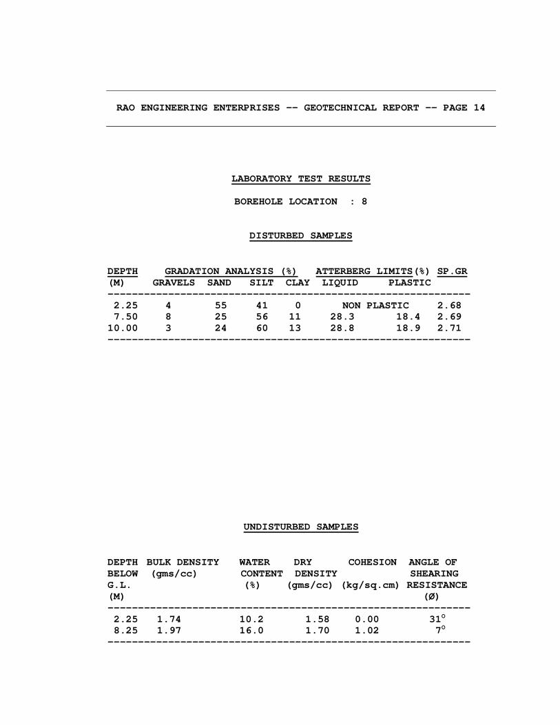
LABORATORY TEST RESULTS
BOREHOLE LOCATION : 8
DISTURBED SAMPLES
DEPTH GRADATION ANALYSIS (%) ATTERBERG LIMITS(%) SP.GR (M) GRAVELS SAND SILT CLAY LIQUID PLASTIC ------------------------------------------------------------ 2.25 4 55 41 0 NON PLASTIC 2.68 7.50 8 25 56 11 28.3 18.4 2.69 10.00 3 24 60 13 28.8 18.9 2.71 ------------------------------------------------------------
UNDISTURBED SAMPLES
DEPTH BULK DENSITY WATER DRY COHESION ANGLE OF BELOW (gms/cc) CONTENT DENSITY SHEARING G.L. (%) (gms/cc) (kg/sq.cm) RESISTANCE (M) (Ø) ------------------------------------------------------------ 2.25 1.74 10.2 1.58 0.00 31O
8.25 1.97 16.0 1.70 1.02 7O
------------------------------------------------------------

RAO ENGINEERING ENTERPRISES -- GEOTECHNICAL REPORT -- PAGE 15
3.0 OBSERVATIONS
Following points are observed from results obtained:
(a) A fill is met at site to about 1.30-4.5m depth. Below fill, the soils met at the site are light brown Silty sand/ Fine sand and Sandy silt to the final explored depth of 10.0m.
(b) Bulk density values vary from 1.74 to 2.01 gms/cc whereas dry density values vary from 1.58 to 1.75 gms./cc. in the eight boreholes.
(c) In silt strata, cohesion varies from 0.58 to 1.06 kg./sq.cm with angle of shearing resistance values range from 5 to 8 degrees. However, in sand strata average cohesion is 0.00 kg./sq.cm and angle of shearing resistance varies from 31 to 32 degrees.
4.0 DISCUSSIONS
For designing the foundation system, the following Parameters are required:
(a) Suitable type of foundation on which the proposed super – structure can be supported.
(b) Depth of these foundations, and
(c) Allowable bearing pressure at the founding level Corresponding to various footing sizes.

RAO ENGINEERING ENTERPRISES -- GEOTECHNICAL REPORT -- PAGE 16
4.1 TYPE & DEPTH OF FOUNDATION
Type of foundation to be adopted for a particular structure depends upon the loading intensity at the foundation level and the configuration of loading points. Reviewing the stratigraphy of the site, SPT values & laboratory test results, We recommend as follows:
(a) At BH-1,2,4 to 8 locations, Isolated Open spread foundations or Raft foundations may be provided at the site to support the structural loads. We recommend a minimum foundation embedment depth of 2.0m below the existing ground surface. However, In any case, it should be ensured that the foundation is seated at-least 0.5m into natural soil below fill formation. Recommendation for the same are provided in section 5.1 of the report.
(b) At BH-3 location, we recommend that
Bored –cast-in-situ Under-reamed piles may be provided at the site. 300mm, 400mm or 450mm diameter Under-reamed piles may be used. Recommendations for the same are provided in section 5.2 of the report.
4.2 ALLOWABLE BEARING PRESSURE FOR OPEN/RAFT FOUNDATIONS
Following criterion have been considered for evaluating the bearing capacity values :
(a) Settlement criteria
(b) Shear failure criterion
Shear failure condition as per I.S. 6403 has been considered for allowable bearing pressure computation.
Allowable settlement value of 50 mm has been considered for deducing shear strength value.

RAO ENGINEERING ENTERPRISES -- GEOTECHNICAL REPORT -- PAGE 17
5.0 RECOMMENDATIONS
5.1 OPEN/RAFT FOUNDATIONS At BH-1,2,4 TO 8 LOCATIONS.
The following table presents our recommended values of net allowable bearing pressure for 1-5m wide Isolated Open Spread foundations or Raft foundations(width>6.0m) bearing at or below 2.0m depth below the existing ground surface. However, In any case, it should be ensured that the foundation is seated at-least 0.5m into natural soil below fill formation.
Foundation Depth below existing ground level, m
Recommended Net Allowable Bearing Pressure, T/m²
2.0 9.2
2.5 11.0
3.0 13.0
The above values include a safety factor of 2.5. Total settlement of foundation designed for the above net bearing pressure is expected to be about 50 mm. Net bearing pressure for foundations at intermediate depths may be interpolated linearly between the values given above.
5.2 UNDER-REAMED PILE FOUNDATIONS AT BH-3 LOCATION Bored cast-in-situ Under-reamed piles are a feasible foundation scheme to support the structural loads at BH-3 location.
The following table presents our recommended Compressive pile capacities for 300 mm, 400mm and 450mm diameter bored piles with a cut off level of 1.0-2.0m below the ground level. For pile capacity design, water table has been considered to rise upto ground surface for worst condition.
RAO ENGINEERING ENTERPRISES -- GEOTECHNICAL REPORT -- PAGE 18
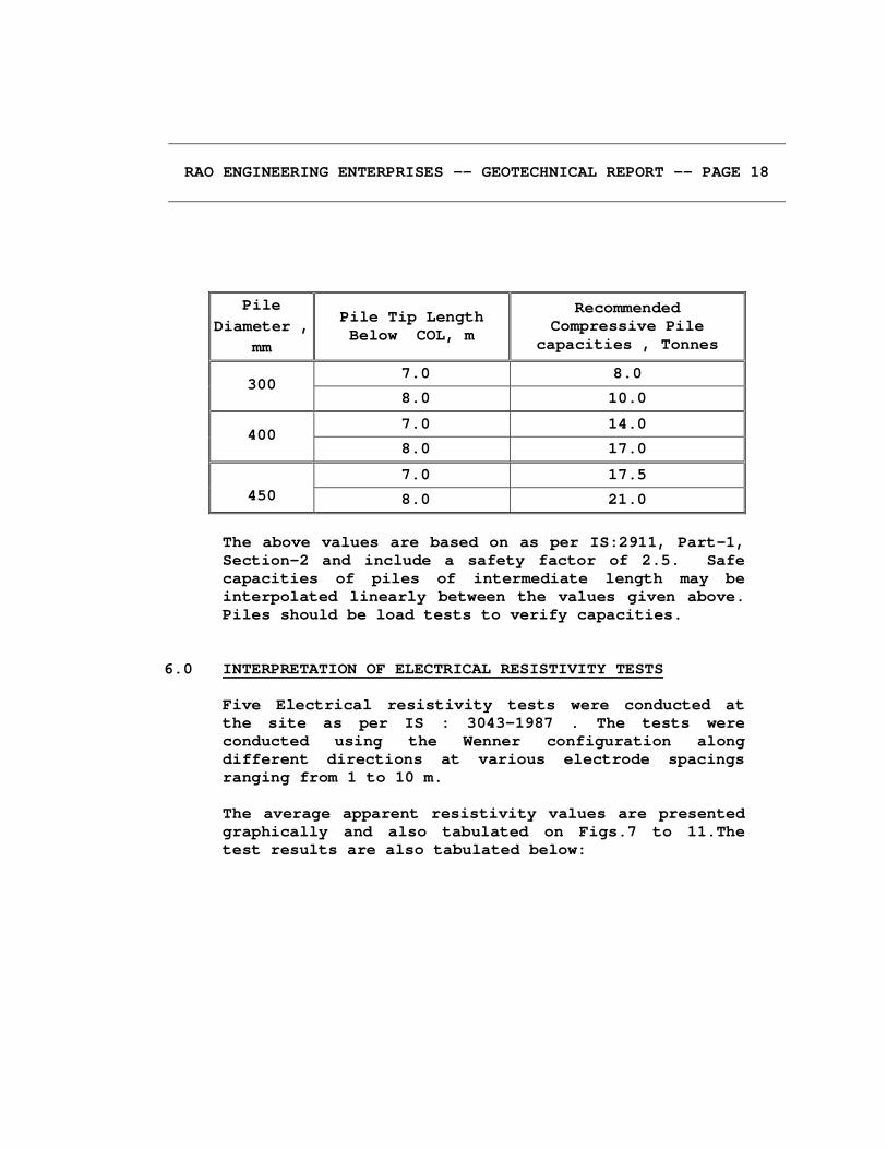
Pile Diameter ,
mm
Pile Tip Length Below COL, m
Recommended Compressive Pile
capacities , Tonnes
7.0 8.0 300
8.0 10.0
7.0 14.0 400
8.0 17.0
7.0 17.5 450 8.0 21.0
The above values are based on as per IS:2911, Part-1, Section-2 and include a safety factor of 2.5. Safe capacities of piles of intermediate length may be interpolated linearly between the values given above. Piles should be load tests to verify capacities.
6.0 INTERPRETATION OF ELECTRICAL RESISTIVITY TESTS
Five Electrical resistivity tests were conducted at the site as per IS : 3043-1987 . The tests were conducted using the Wenner configuration along different directions at various electrode spacings ranging from 1 to 10 m. The average apparent resistivity values are presented graphically and also tabulated on Figs.7 to 11.The test results are also tabulated below:
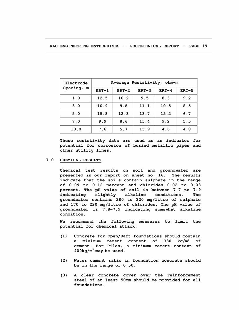
RAO ENGINEERING ENTERPRISES -- GEOTECHNICAL REPORT -- PAGE 19
Average Resistivity, ohm-m Electrode Spacing, m
ERT-1 ERT-2 ERT-3 ERT-4 ERT-5
1.0 12.5 10.2 9.5 8.3 9.2
3.0 10.9 9.8 11.1 10.5 8.5
5.0 15.8 12.3 13.7 15.2 6.7
7.0 9.9 8.6 15.4 9.2 5.5
10.0 7.6 5.7 15.9 4.6 4.8
These resistivity data are used as an indicator for potential for corrosion of buried metallic pipes and other utility lines.
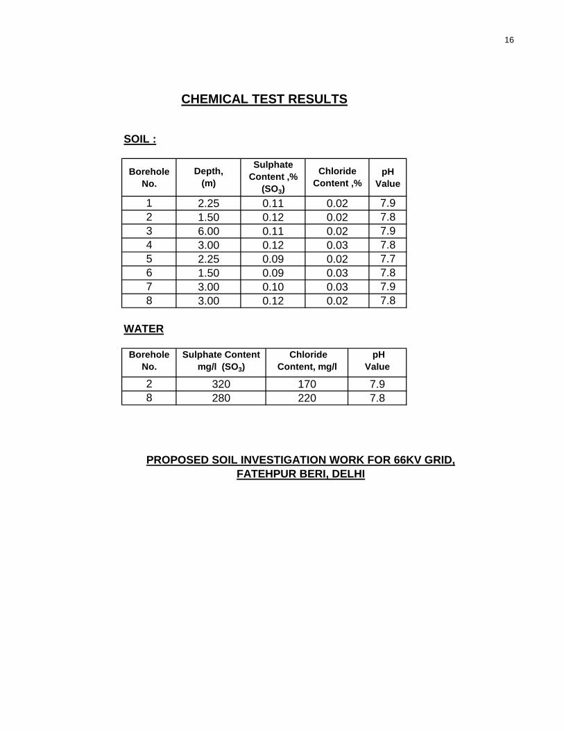
7.0 CHEMICAL RESULTS
Chemical test results on soil and groundwater are presented in our report on sheet no. 16. The results indicate that the soils contain sulphate in the range of 0.09 to 0.12 percent and chlorides 0.02 to 0.03 percent. The pH value of soil is between 7.7 to 7.9 indicating slightly alkaline conditions. The groundwater contains 280 to 320 mg/litre of sulphate and 170 to 220 mg/litre of chlorides. The pH value of groundwater is 7.8-7.9 indicating somewhat alkaline condition.
We recommend the following measures to limit the potential for chemical attack:
(1) Concrete for Open/Raft foundations should contain a minimum cement content of 330 kg/m3 of
cement. For Piles, a minimum cement content of 400kg/m3 may be used.
(2) Water cement ratio in foundation concrete should
be in the range of 0.50. (3) A clear concrete cover over the reinforcement
steel of at least 50mm should be provided for all foundations.

RAO ENGINEERING ENTERPRISES -- GEOTECHNICAL REPORT -- PAGE 20
8.0 CLOSURE
We appreciate the opportunity to perform this investigation for you and have pleasure in submitting this report. Please contact us when we can be of further service to you.
For RAO ENGINEERING ENTERPRISES
(G.R.RAO) ( PUSHPENDRA KUMAR ) DIRECTOR EXECUTIVE DIRECTOR

1
SYMBOL
FATEHPUR BERI, DELHIPROPOSED SOIL INVESTIGATION WORK FOR 66KV GRID,
Sandy silt
LEGEND
DESCRIPTION
Silty sand
Water table
Fill
6
D E
P T
H,
m0
SUMMARY OF BOREHOLE PROFILE
N-ValueBH-1
13
15
18
N-ValueBH-2
22
16
1
2
3
4
5
7
10.00m
8
20
25
30
9
10
24 34
11 14
N-ValueBH-3
10.00m
18
20
24
N-ValueBH-4
21
18
10.00m
30
35
22
22
6.70m 6.70m 6.60m 6.70m
10.00m
1.4m
4.5m
28 39 33 28
1.3m1.3m10
3
2

2
SYMBOL
FATEHPUR BERI,DELHIPROPOSED SOIL INVESTIGATION WORK FOR 66KV GRID,
Sandy silt
LEGEND
DESCRIPTION
Silty sand
Water table
Fill
Fine sand
6
D E
P T
H,
m0
SUMMARY OF BOREHOLE PROFILE
N-ValueBH-5
21
28
25
N-ValueBH-6
23
18
1
2
3
4
5
7
10.00m
8
29
39
27
9
10
33 35
12 14
N-ValueBH-7
10.00m
40
48
37
N-ValueBH-8
31
19
10.00m
33
31
41
20
6.50m6.80m 6.65m 6.70m
10.00m
1.35m1.40m
39 49 39 45
1.50m1.45m
3.00m 3.00m 3.00m
18
23
27
3
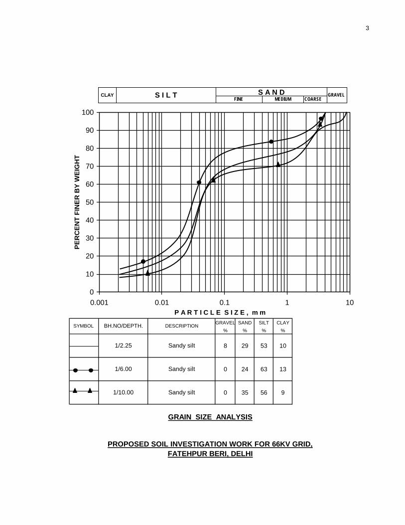
GRAVEL SAND SILT CLAY% % % %
8 29 53 10
0 24 63 13
0 35 56 9
GRAIN SIZE ANALYSIS
PROPOSED SOIL INVESTIGATION WORK FOR 66KV GRID,FATEHPUR BERI, DELHI
1/2.25
SYMBOL DESCRIPTION
Sandy silt
Sandy silt
Sandy silt1/6.00
1/10.00
BH.NO/DEPTH.
0
10
20
30
40
50
60
70
80
90
100
0.001 0.01 0.1 1 10P A R T I C L E S I Z E , m m
PER
CEN
T FI
NER
BY
WEI
GH
T
GRAVELFINE MEDIUMS I L T COARSE
S A N DCLAY

4
GRAVEL SAND SILT CLAY% % % %
0 25 64 11
0 34 56 10
2 31 58 9
GRAIN SIZE ANALYSIS
PROPOSED SOIL INVESTIGATION WORK FOR 66KV GRID,FATEHPUR BERI, DELHI
2/2.25
SYMBOL DESCRIPTION
Sandy silt
Sandy silt
Sandy silt2/7.50
2/10.00
BH.NO/DEPTH.
0
10
20
30
40
50
60
70
80
90
100
0.001 0.01 0.1 1 10P A R T I C L E S I Z E , m m
PER
CEN
T FI
NER
BY
WEI
GH
T
GRAVELFINE MEDIUMS I L T COARSE
S A N DCLAY

5
GRAVEL SAND SILT CLAY% % % %
3 28 58 11
0 25 63 12
3/6.00
SYMBOL DESCRIPTION
Sandy silt
Sandy silt3/9.00
BH.NO/DEPTH.
GRAIN SIZE ANALYSIS
PROPOSED SOIL INVESTIGATION WORK FOR 66KV GRID,FATEHPUR BERI, DELHI
0
10
20
30
40
50
60
70
80
90
100
0.001 0.01 0.1 1 10P A R T I C L E S I Z E , m m
PER
CEN
T FI
NER
BY
WEI
GH
T
GRAVELFINE MEDIUMS I L T COARSE
S A N DCLAY

6
GRAVEL SAND SILT CLAY% % % %
0 27 62 11
5 32 51 12
2 35 54 9
4/1.50
SYMBOL DESCRIPTION
Sandy silt
Sandy silt
Sandy silt4/5.25
4/9.00
BH.NO/DEPTH.
GRAIN SIZE ANALYSIS
PROPOSED SOIL INVESTIGATION WORK FOR 66KV GRID,FATEHPUR BERI, DELHI
0
10
20
30
40
50
60
70
80
90
100
0.001 0.01 0.1 1 10P A R T I C L E S I Z E , m m
PER
CEN
T FI
NER
BY
WEI
GH
T
GRAVELFINE MEDIUMS I L T COARSE
S A N DCLAY

7
GRAVEL SAND SILT CLAY% % % %
2 62 36 0
4 33 52 11
0 28 62 10
GRAIN SIZE ANALYSIS
PROPOSED SOIL INVESTIGATION WORK FOR 66KV GRID,FATEHPUR BERI, DELHI
5/1.50
SYMBOL DESCRIPTION
Sandy silt
Silty sand
Sandy silt5/5.25
5/9.00
BH.NO/DEPTH.
0
10
20
30
40
50
60
70
80
90
100
0.001 0.01 0.1 1 10P A R T I C L E S I Z E , m m
PER
CEN
T FI
NER
BY
WEI
GH
T
GRAVELFINE MEDIUMS I L T COARSE
S A N DCLAY

8
GRAVEL SAND SILT CLAY% % % %
0 89 11 0
4 29 57 10
0 25 63 12
6/3.00
SYMBOL DESCRIPTION
Sandy silt
Fine sand
Sandy silt6/6.00
6/10.00
BH.NO/DEPTH.
GRAIN SIZE ANALYSIS
PROPOSED SOIL INVESTIGATION WORK FOR 66KV GRID,FATEHPUR BERI, DELHI
0
10
20
30
40
50
60
70
80
90
100
0.001 0.01 0.1 1 10P A R T I C L E S I Z E , m m
PER
CEN
T FI
NER
BY
WEI
GH
T
GRAVELFINE MEDIUMS I L T COARSE
S A N DCLAY

9
GRAVEL SAND SILT CLAY% % % %
0 27 61 12
3 34 54 9
5 26 58 11
GRAIN SIZE ANALYSIS
PROPOSED SOIL INVESTIGATION WORK FOR 66KV GRID,FATEHPUR BERI, DELHI
7/2.25
SYMBOL DESCRIPTION
Sandy silt
Sandy silt
Sandy silt7/6.00
7/9.00
BH.NO/DEPTH.
0
10
20
30
40
50
60
70
80
90
100
0.001 0.01 0.1 1 10P A R T I C L E S I Z E , m m
PER
CEN
T FI
NER
BY
WEI
GH
T
GRAVELFINE MEDIUMS I L T COARSE
S A N DCLAY
10
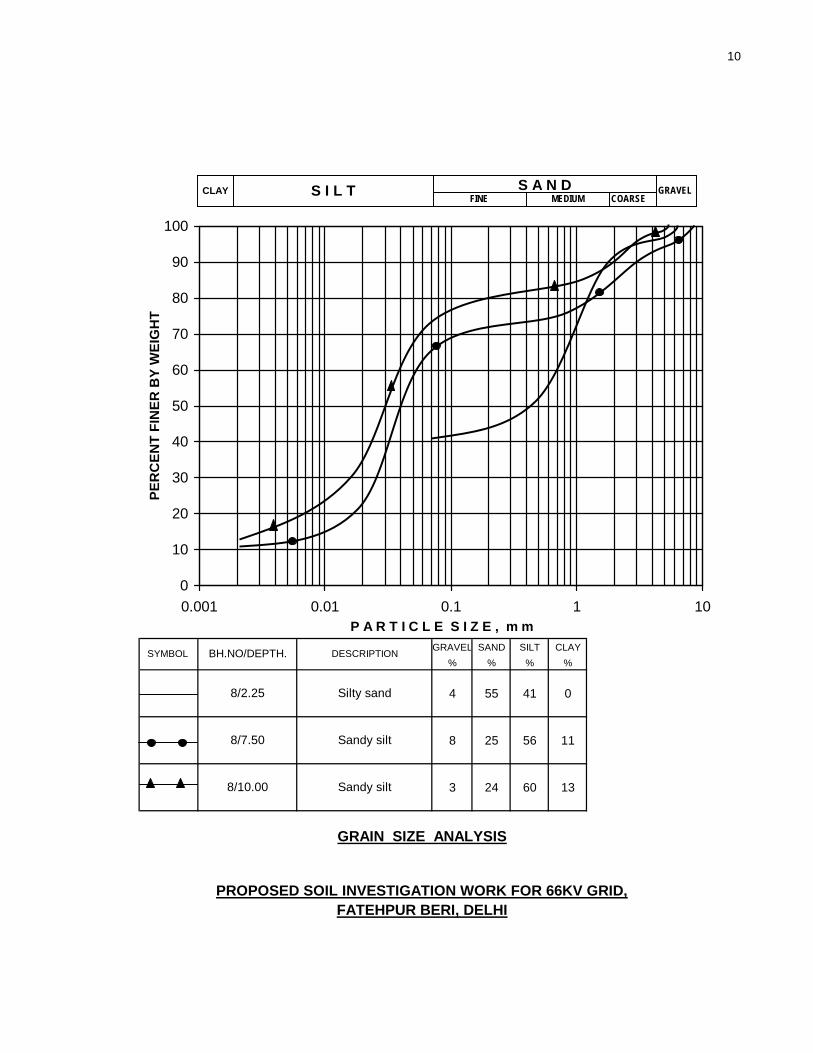
GRAVEL SAND SILT CLAY% % % %
4 55 41 0
8 25 56 11
3 24 60 13
8/2.25
SYMBOL DESCRIPTION
Sandy silt
Silty sand
Sandy silt8/7.50
8/10.00
BH.NO/DEPTH.
GRAIN SIZE ANALYSIS
PROPOSED SOIL INVESTIGATION WORK FOR 66KV GRID,FATEHPUR BERI, DELHI
0
10
20
30
40
50
60
70
80
90
100
0.001 0.01 0.1 1 10P A R T I C L E S I Z E , m m
PER
CEN
T FI
NER
BY
WEI
GH
T
GRAVELFINE MEDIUMS I L T COARSE
S A N DCLAY

11
Electode ApparentSpacing,m Resistivity, Ohm-m
1.0 12.53.0 10.95.0 15.87.0 9.910.0 7.6
ELECTRICAL RESISTIVITY TEST NO - 1
1
10
100
0 2 4 6 8 10 12 14 16Electrode Spacing , m
App
aren
t Res
istiv
ity ,O
hm-m
PROPOSED SOIL INVESTIGATION WORK FOR 66KV GRID,FATEHPUR BERI, DELHI

12
Electode ApparentSpacing,m Resistivity, Ohm-m
1.0 10.23.0 9.85.0 12.37.0 8.610.0 5.7
ELECTRICAL RESISTIVITY TEST NO - 2
1
10
100
0 2 4 6 8 10 12 14 16Electrode Spacing , m
App
aren
t Res
istiv
ity ,O
hm-m
PROPOSED SOIL INVESTIGATION WORK FOR 66KV GRID,FATEHPUR BERI, DELHI

13
Electode ApparentSpacing,m Resistivity, Ohm-m
1.0 9.53.0 11.15.0 13.77.0 15.410.0 15.9
ELECTRICAL RESISTIVITY TEST NO - 3
1
10
100
0 2 4 6 8 10 12 14 16Electrode Spacing , m
App
aren
t Res
istiv
ity ,O
hm-m
PROPOSED SOIL INVESTIGATION WORK FOR 66KV GRID,FATEHPUR BERI, DELHI

14
Electode ApparentSpacing,m Resistivity, Ohm-m
1.0 8.33.0 10.55.0 15.27.0 9.210.0 4.6
ELECTRICAL RESISTIVITY TEST NO - 4
1
10
100
0 2 4 6 8 10 12 14 16Electrode Spacing , m
App
aren
t Res
istiv
ity ,O
hm-m
PROPOSED SOIL INVESTIGATION WORK FOR 66KV GRID,FATEHPUR BERI, DELHI

15
Electode ApparentSpacing,m Resistivity, Ohm-m
1.0 9.23.0 8.55.0 6.77.0 5.510.0 4.8
ELECTRICAL RESISTIVITY TEST NO - 5
1
10
100
0 2 4 6 8 10 12 14 16Electrode Spacing , m
App
aren
t Res
istiv
ity ,O
hm-m
PROPOSED SOIL INVESTIGATION WORK FOR 66KV GRID,FATEHPUR BERI, DELHI
16
SOIL :
Borehole No.
pH Value
1 7.92 7.83 7.94 7.85 7.76 7.87 7.98 7.8
WATER
Borehole No.
28
2.25 0.11 0.02
3.00 0.10 0.03
CHEMICAL TEST RESULTS
Depth, (m)
Sulphate Content ,%
(SO3)
Chloride Content ,%
1.50
7.9
0.020.030.020.03
0.12 0.02
Sulphate Content mg/l (SO3)
Chloride Content, mg/l
320 170
0.12 0.02
280 220 7.8
pH Value
3.00
PROPOSED SOIL INVESTIGATION WORK FOR 66KV GRID,FATEHPUR BERI, DELHI
6.003.00
0.110.120.090.09
2.251.50