random vibration and torque tests of fasteners … vibration and torque tests of fasteners secured...
TRANSCRIPT

NASA Technical Memorandum 108539
Random Vibration and Torque Tests of Fasteners
Secured With Cable, Room Temperature Vulcanized(RTV) Rubber, and Closed Cell Foam to Supportthe Launch of STS-82V.H. Yost
Marshall Space Flight Center • MSFC, Alabama
August 1997
https://ntrs.nasa.gov/search.jsp?R=19970034682 2018-06-18T07:00:52+00:00Z


TABLE OF CONTENTS
II.
I. INTRODUCTION ........................................................................................................................ 1
DESCRIPTION ............................................................................................................................ 2
A. Random Vibration Tests ........................................................................................................... 2
B. Torque Tests ............................................................................................................................. 9
III. CONCLUSIONS .......................................................................................................................... 11
A. Random Vibration Tests ........................................................................................................... 11
B. Torque Tests ............................................................................................................................. 11
C. General ..................................................................................................................................... 11
IV. RECOMMENDATION ................................................................................................................ 12
APPENDIX A--CONTRIBUTORS ..................................................................................................... 13
APPENDIX B--SSME VIBRATION CRITERIA, ZONE D ............................................................... 15
APPENDIX C--RANDOM VIBRATION TEST DATA ...................................................................... 16
APPENDIX D--GRAPHS: RANDOM VIBRATION VERSUS TIME .............................................. 17
APPENDIX E--RTV APPLICATION DESCRIPTION ....................................................................... 24
APPENDIX F--TORQUE TEST DATA .............................................................................................. 25
iii

LIST OF FIGURES
lo
2.
3.
4.
5.
,
7.
8.
9.
10.
11.
12.
13.
D-1.
D-2.
D-3.
D-4.
D-5.
D-6.
D-7.
Vibration test fixture (VTF) .......................................................................................................... 3
Vibration machine with VTF ........................................................................................................ 4
VTF with loosened fasteners after run 1 ...................................................................................... 5
VTF with loosened 0.250-inch bolt after run 1 ............................................................................ 5
VTF with loosened 0.375-inch stud after run 1 ............................................................................ 5
VTF with loosened 0.4375-inch bolt after run 2 .......................................................................... 6
VTF with loosened 0.375-inch stud after run 3 ............................................................................ 6
VTF with loosened fasteners after run 3 ...................................................................................... 6
VTF with foam removed after run 4 ............................................................................................. 7
The 0.250-inch bolt with cable, and RTV and foam removed after run 4 .................................... 8
The 0.4375-inch bolt with cable, and RTV and foam removed after run 4 .................................. 8
The 0.375-inch stud with RTV and foam removed after run 4 ..................................................... 8
Torque test fixture (TTF) .............................................................................................................. 10
Run 2, at 48 seconds ..................................................................................................................... 17
Run 3, part 1, at 42 seconds .............................................................................................. . ........... 18
Run 3, part 2, at 16 seconds .......................................................................................................... 19
Run 3, part 3, at 46 seconds .......................................................................................................... 20
Run 3, part 4, at 43 seconds .......................................................................................................... 21
Run 3, part 3, at 35 seconds .......................................................................................................... 22
Run 4, at 39 seconds ..................................................................................................................... 23
iv

TECHNICAL MEMORANDUM
RANDOM VIBRATION AND TORQUE TESTS OF FASTENERS SECURED
WITH LOCKING CABLE, ROOM TEMPERATURE VULCANIZED (RTV) RUBBER,
AND CLOSED CELL FOAM TO SUPPORT THE LAUNCH OF STS-82
I. INTRODUCTION
Before every flight of the Space Transportation System (STS), technicians at the Kennedy
Space Center (KSC) inspect the system. This inspection is called a walkdown. During a walkdown of
the orbiter for STS-82, technicians found several safety cables for bolts with missing or loose ferrules.
Typically, two or three bolts are secured with a cable which passes through one of the holes in the head
of each bolt and a ferrule is crimped on each end of the cable to prevent it from coming out of the holes.
The purpose of the cable is to prevent bolts from rotating should they become untightened. Two joints
where the Space Shuttle main engine (SSME) is bolted to the orbiter are where missing and loose
ferrules were found. These joints are F1, low pressure fuel pump, and F4.3, fuel bleed line. These
discrepancies were recorded at KSC on an Inspection Discrepancy and Correction Record form.
However, there are a number of other bolts on the orbiter that are secured with lock wire or cable with
ferrules, then the bolt head and wire or cable are covered with room temperature vulcanized (RTV)
rubber which is allowed to cure before they are covered with foam insulation. These bolts and lock
wires or cables with ferrules cannot be inspected without removing the foam.
The Associate Director, Technical, at the Marshall Space Flight Center (MSFC), directed that
tests be made at MSFC to determine whether bolts with locking cables with no ferrules which are
covered with RTV rubber and foam will untighten when subjected to the same random vibration as the
SSME. The test fixtures and tests were made between February 3 and 10, 1997, at MSFC. The
participants and their contributions are listed in appendix A.

11. DESCRIPTION
A. Random Vibration Tests
1. Fixture, Equipment, and Supplies
• Vibration test fixture.
• Molykote, G-N paste, Dow Coming Corporation, Midland, MI.
• Cable, 3 strands × 7 wires, 0.006-inch diameter per strand and a nominal diameter for thecable of 0.035 inch.
• Room temperature vulcanized rubber, a.k.a. Silicone Elastomer, MIL-A-46106B,
Accumetric, Inc., Elizabethtown, KY 42701.
• Epoxi-Patch kit, Hysol 608, NSN 8040-00539-7798, The Dexter Corporation, Seabrook,NH 03874-4018.
• Great Stuff Minimal Expanding Foam Sealant, Insta-Foam Products, Inc., A Division of
Flexible Products Co., Joliet, IL 60435-3187.
• Master heat gun, 300/500 °E Model HG-301A, Master Appliance Corp., Racine,WI 53403.
• Proheat VAR (temp. heat gun), 1,500 W, model PH 1200, Master Appliance Corp., Racine,WI 53403.
• Torque wrench, 0-600 inch-pounds, Snap-On Tools Corp., Kenosha, WI (calibration
identification number N028262, calibrated 9/12/96, due 3/12/97).
• Torque wrench, 0-75 inch-pounds, Snap-On Tools Corp., Kenosha, WI (calibration
identification number M631281, calibrated 11/5/96, due 5/5/97).
• Vibration machine, KI number K4523, Kimball Industries, Inc., Monrovia, CA.
2. Documents
• Bolt, spline drive, reduced shank, short thread, ultrasonic length, alloy 718, 220 ksi,
Rockwell International Corp., drawing number RD 111-4101.
• Applied room temperature cured silicone sealing compound, Rockwell International Corp.,
specification number MA01106-303, figure 2 and installation--SSME interface, drawing
number V0410801, view H and sections F-F and G-G.
• SSME Structural Design Criteria, BNA Rocketdyne Division RSS-8561-25, May 23, 1996,
SSME Vibration Criteria, Zone D, pages 4-56.
• Standard, threaded fasteners, torque limits for, MSFC-STD-486A, December 11, 1987.
3. Test Setup
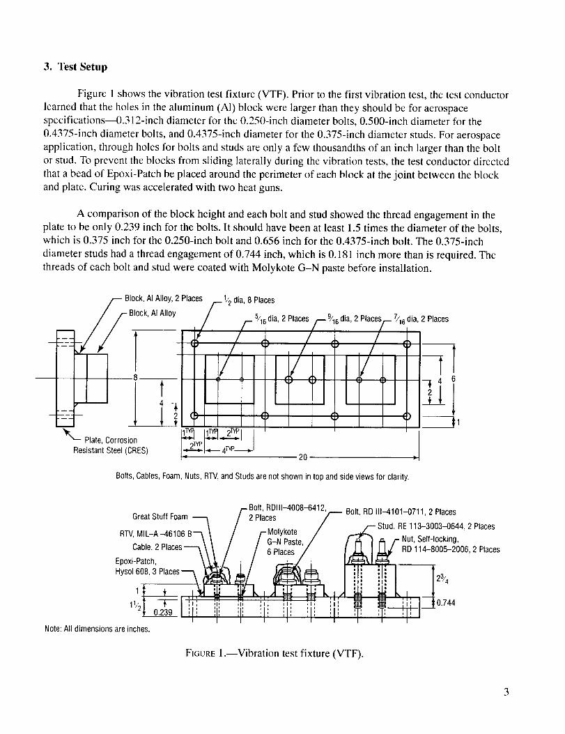
Figure 1 shows the vibration test fixture (VTF). Prior to the first vibration test, the test conductor
learned that the holes in the aluminum (AI) block were larger than they should be for aerospace
specifications--0.312-inch diameter for the 0.250-inch diameter bolts, 0.500-inch diameter for the
0.4375-inch diameter bolts, and 0.4375-inch diameter for the 0.375-inch diameter studs. For aerospace
application, through holes for bolts and studs are only a few thousandths of an inch larger than the bolt
or stud. To prevent the blocks from sliding laterally during the vibration tests, the test conductor directed
that a bead of Epoxi-Patch be placed around the perimeter of each block at the joint between the block
and plate. Curing was accelerated with two heat guns.
A comparison of the block height and each bolt and stud showed the thread engagement in the
plate to be only 0.239 inch for the bolts. It should have been at least 1.5 times the diameter of the bolts,
which is 0.375 inch for the 0.250-inch bolt and 0.656 inch for the 0.4375-inch bolt. The 0.375-inch
diameter studs had a thread engagement of 0.744 inch, which is 0.181 inch more than is required. The
threads of each bolt and stud were coated with Molykote G-N paste before installation.
m
__Block, AI Alloy, 2 Places/._ 1/2 alia, 8 PlacesBlock, AI Alloy_ ()/ / ,_ 5/16dia, 2 Places
• /
_'-- Plate, Corrosion
8
4
Resistant Steel (CRES)
-i2 (:)t
_____1
9/16 alia,2 Places_ 7/16 alia,2 Places
,, / ,, /
/ / T) () ¢9
20
Bolts, Cables, Foam, Nuts, Rrv, and Studs are not shown in top and side views for clarity.
,-Bolt, RDIII-4008-6412, Bolt
Great Stuff Foam _ /2 Places F '
RFV, MIL-A-46106 B_ \ / /-Molykote /
Cable,Places--- \/ //6P,acesEpoxi-Patch, \ _,___/ ; / .-.;-./ i :Hyso1608,3Places_ ,,_ _/ ),,_ _ I, I
• X-!F____l ____ tn_:===_,lt===_ I :_
_i/ot -rl i;! i_- ',,; ';' ',i ;,_ ],izt o.239Iiii ',1', ]11 iii il', il iii
I I I I I I I I
Note: All dimensions are inches.
RD 111--4101-0711,2 Places
Stud, RE 113-3003-0644, 2 Places
_ _/-- Nut, Self-locking,
_l_ RD 114-8005-2006,2 Places
!lil
r o.,4I I
FIGURE 1.--Vibration test fixture (VTF).
3

Figure 2 shows the VTF bolted to the vibration machine table and the accelerometer used to
measure the vibration to which the VTF was subjected. It also shows the bolts which were secured by
cable, RTV, and Great Stuff Expanding Foam and those that were not, as well as the stud that was
secured by RTV and foam and the stud that was not.
FIGURE 2.--Vibration machine with VTE
4. Discussion
The purpose of the vibration tests was to determine whether bolts and studs tightened to various
degrees--both secured and not secured with various combinations of cable, RTV, and foam--will loosen
when subjected to one of the several SSME random vibration criteria.
For the first vibration test (run 1), all bolts and studs were finger-tight. The random vibration
requested was for the SSME Vibration Criteria, Zone D (see appendix B). Prior to this test, these
random vibrations caused an electrical fusible link in another vibration machine to fail. So, for this
test, the vibration machine shown in figure 2 was run at -3 dB below the levels shown in appendix B
(44.94 grms versus 63.48 grms). After 31 seconds at this level, the unsecured 0.250-inch bolt rotated
counterclockwise (loosened) 80 degrees, and the 0.4375-inch bolt and 0.375-inch bolt loosened
60 degrees. The data recorded for this and all other vibration tests are in appendix C. Figure 3 shows
the VTF and loosened bolts after run 1. Figures 4 and 5 show the loosening of 0.250-inch bolt and
0.375-inch stud at 80 and 60 degrees, respectively.

ii:ii!ii
FIGURE 3.--VTF and loosened fasteners after run 1.
FIGURE 4.--VTF with loosened 0.250-inch bolt
after run 1.
FIGURE 5.--VTF with loosened 0.375-inch stud
after run 1.
5
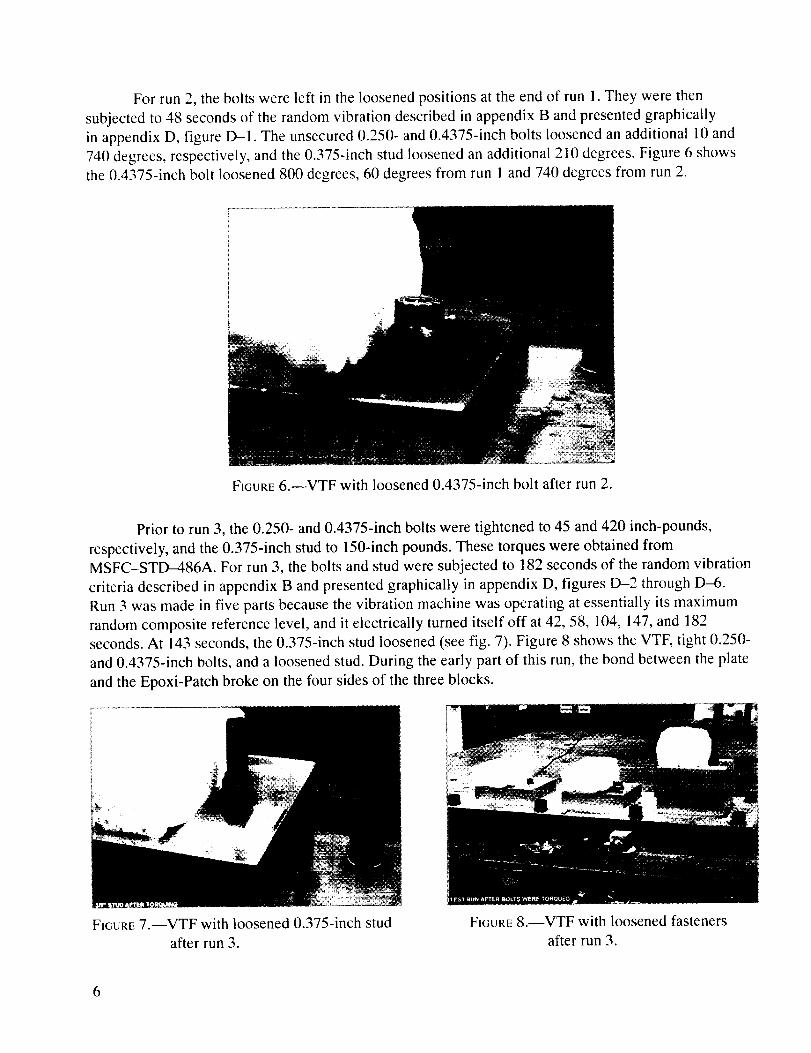
Forrun2, theboltswereleft in the loosenedpositionsat theendof run 1.Theywerethensubjectedto 48secondsof therandomvibrationdescribedin appendixB andpresentedgraphicallyin appendixD, figure D-1. Theunsecured0.250-and0.4375-inchbolts loosenedanadditional10and740degrees,respectively,andthe0.375-inchstudloosenedanadditional210degrees.Figure6 showsthe0.4375-inchbolt loosened800degrees,60degreesfrom run 1and740degreesfrom run2.
FIGURE6.--VTF with loosened0.4375-inchbolt afterrun2.
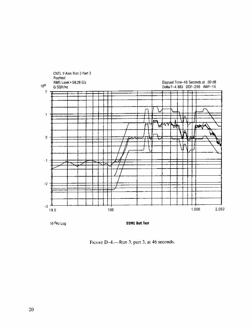
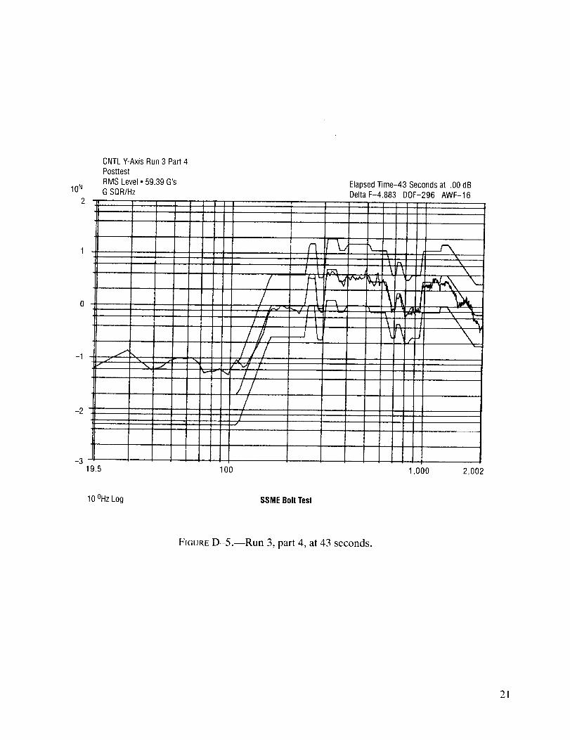
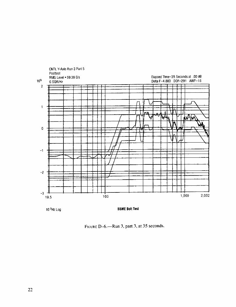
Prior to run3, the0.250-and0.4375-inchboltsweretightenedto 45and420 inch-pounds,respectively,andthe0.375-inchstudto 150-inchpounds.ThesetorqueswereobtainedfromMSFC-STD-486A.For run3, theboltsandstudweresubjectedto 182secondsof therandomvibrationcriteriadescribedin appendixB andpresentedgraphicallyin appendixD, figuresD-2 throughD-6.Run3 wasmadein five partsbecausethevibrationmachinewasoperatingatessentiallyits maximumrandomcompositereferencelevel,andit electricallyturneditself off at42,58, 104,147,and182seconds.At 143seconds,the0.375-inchstudloosened(seefig. 7). Figure8 showstheVTF,tight 0.250-and0.4375-inchbolts,andaloosenedstud.During theearly partof this run, thebondbetweentheplateandtheEpoxi-Patchbrokeon thefour sidesof thethreeblocks.
FIGURE7.--VTF with loosened0.375-inchstudafterrun3.
FIGURE8.--VTF with loosenedfastenersafterrun3.
6
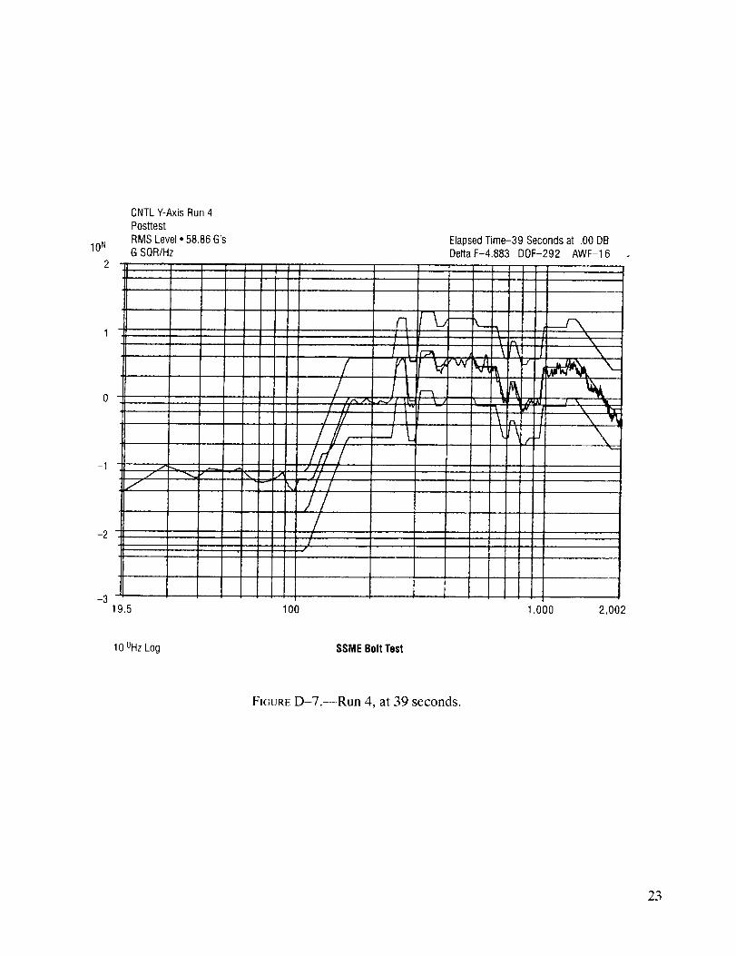
For run4, theboltsandstudweresubjectedto 39secondsof therandomvibrationdescribedinappendixB andpresentedgraphicallyin appendix D, figure D-7. During this test, the test conductor
placed his finger on the top of the loosened stud to determine by touch if much torque was required to
prevent the stud from loosening more. The torque was estimated to be only a few inch-pounds. The
0.250- and 0.4375-inch bolts did not loosen during run 4.
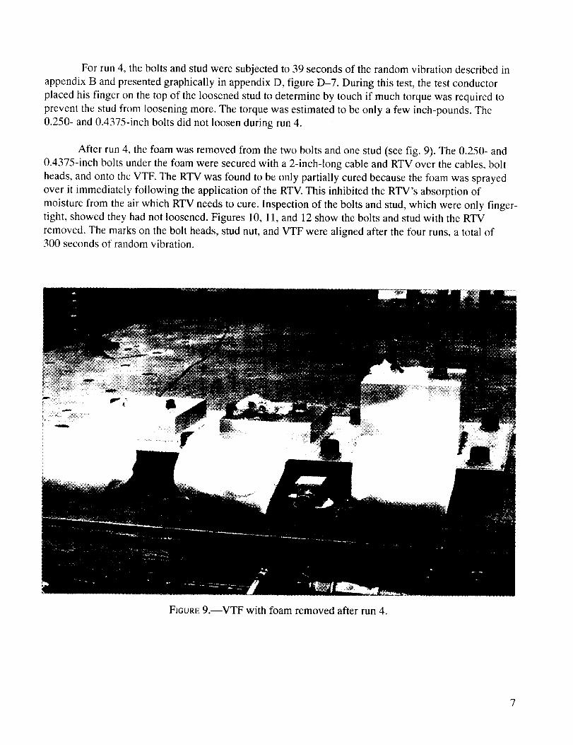
After run 4, the foam was removed from the two bolts and one stud (see fig. 9). The 0.250- and
0.4375-inch bolts under the foam were secured with a 2-inch-long cable and RTV over the cables, bolt
heads, and onto the VTF. The RTV was found to be only partially cured because the foam was sprayed
over it immediately following the application of the RTV. This inhibited the RTV's absorption of
moisture from the air which RTV needs to cure. Inspection of the bolts and stud, which were only finger-
tight, showed they had not loosened. Figures 10, 11, and 12 show the bolts and stud with the RTV
removed. The marks on the bolt heads, stud nut, and VTF were aligned after the four runs, a total of300 seconds of random vibration.
FIGURE 9.--VTF with foam removed after run 4.
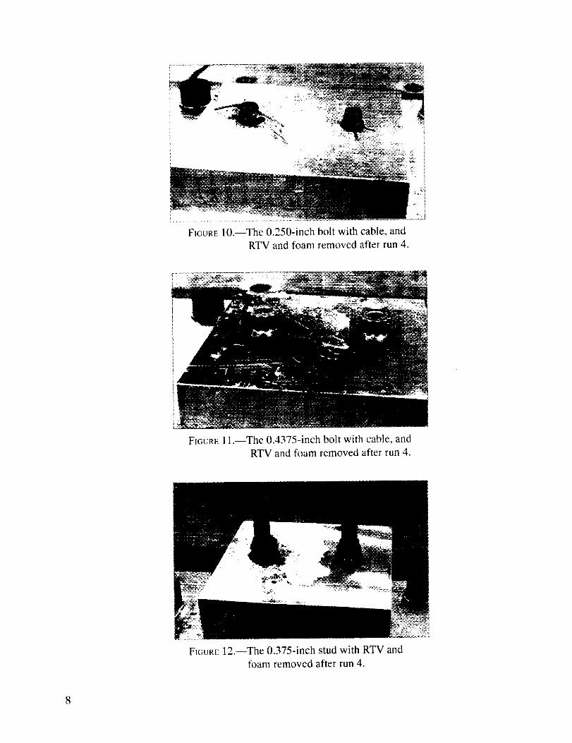
FIGURE 10.--The 0.250-inch bolt with cable, and
RTV and foam removed after run 4.
FIGURE 11.--The 0.4375-inch bolt with cable, and
RTV and foam removed after run 4.
FIGURE 12.--The 0.375-inch stud with RTV and
foam removed after run 4.
8

B. Torque Tests
1. Fixture, Equipment, and Supplies
• Torque test fixture.
• Bolt, external wrench, A-286, 20,000 psi, Rockwell International Corp., standardRD 1114008 and 111-4009
• Bolt, locking cable, 3 strands x 7 wires, 0.006-inch diameter per strand and a nominaldiameter for the cable of 0.035 inch
• Great Stuff Minimal Expanding Foam Sealant, Insta-Foam Products, Inc., a division of
Flexible Products Co., Joliet, IL 60435-3187.
• Nut, check, AN 316-4, 316-5, and 316-6.
• Torque wrench, 0-30 inch-pounds, Snap-On Tools Corp., Kenosha, WI
(calibration identification number M26844, calibrated 8/15/96, due 2/15/97).
2. Documents
Applied room temperature cured silicone sealing compound, Rockwell International Corp.,
specification number MA0106-303, figure 2 and installation--SSME interface, drawing number
V0410801, view H and sections F-F and G-G
3. Test Setup
Figure 13 is an illustration of the torque test fixture (TTF) and the combination of cable, RTV,
and foam for each bolt. The bolts at locations 1, 3, 4, and 6 did not have cables, so only RTV and foamwere used to secure them.
The holes in the plate were larger than they should be for aerospace applications. Holes 1 and 2
were 0.4375-inch diameter for the 0.375-inch diameter bolts, holes 3 and 4 were 0.375-inch diameter for
the 0.3125-inch diameter bolts, and holes 5 and 6 were 0.3125-inch diameter for the 0.250-inch diameterbolts.
The bolts were mounted in the plate and one cable, approximately 2 inches long, was threaded
through a hole in the head of bolts 2 and 5. Then the bolt heads and cables were covered with RTV as
described in appendix E. Next, RTV was cured in air for 6 hours. Finally, the bolt heads, cables, and
RTV were covered with Great Stuff Foam, which was cured for 16 hours. Prior to the torque tests, the
plate was laid foam-down on a bench so the torque wrench with the appropriate socket could be placed
on the double nuts with the wrench dial facing up.
9

S Plate,Low CarbonSteel
/- 7_16dia, r 3_8dia, tm 5/16dia,
r_ z Location: 1¢/ 2 , 4l b_ b
2L
l 7 9 "l .. 11 '
40 m
Bolts, cables, foam, nuts, and RTVare not shown in top and side views for clarity.
,--Cable, 2 Places
GreatStuff Foam___ _ _,*_,_
RTV,RBO120-005, Type009, 6 Places__i'Ii i ill i i _ .,i. .i,. ,t, • •
Bolt, RDlll-4101-O624,2PlacesJ_ _ _ _ /_
Nut Check, J" ' _ //_ L-Bolt RDIII-4008-64, 2 Places
AN 316-3, 2 Each, 2 Places _' ' L Boit, BDIII-400i_-6532, 2 Places
Nut Check,AN 316-5 --"2 Each, 2 Places
FIGURE 13.--Torque test fixture (TTF).
4. Discussion
There were two purposes for the torque test. The first was to determine the torque required to
break the bond between bolts, secured by combinations of cable, RTV, and foam, and the plate in which
the bolts were mounted in through holes. The second was to determine the torque required to rotate the
bolts in the holes once the bond was broken. The torque test made on each bolt consisted of two parts.
First, the torque required to break the aforementioned bond between the plate and bolt was reached, and
the break torque was measured. Second, the torque required to rotate each bolt after the bond was
broken, the run torque, was measured. The data for these tests are in appendix F.
For the 0.375-inch diameter bolts, the break torque was 0.5 inch-pounds greater for bolt 2,
which had the cable through its head, than for bolt 1 (7 versus 6.5 inch-pounds). However, once the bond
with the plate was broken for these bolts, bolt 1, which did not have the cable, had the greater run torque
(3 versus 2 inch-pounds). Bolts 3 and 4 are 0.3125-inch diameter and did not have cables, only RTV andfoam. Like the 0.375-inch diameter bolts, the break torques were within 0.5 inch-pounds of each other
(bolt 3, 4 inch-pounds, and bolt 4, 3.5 inch-pounds). The run torques were also within 0.5 inch-pound
of each other. Bolt 3 had the lower torque (bolt 3, 1.5 inch-pounds, and bolt 4, 2.0 inch-pounds).
For the 0.250-inch diameter bolts, bolt 5--which was secured with a cable, RTV, and foam--had
nearly twice the break torque as bolt 6, which was secured RTV and foam (bolt 5, 3.5 inch-pounds and
bolt 6, 2 inch-pounds). Both bolts had a run torque about one-half the break torque (1.5 inch-pounds).
10

II1. CONCLUSIONS
A. Random Vibration Tests
1. Bolts which were finger-tight, had anti-seize compound on their threads, had less than the
required thread engagement, and were secured with cable, RTV, and foam did not loosen when subjected
to one of the many SSME random vibration criteria (SSME random vibration).
2. The stud, which was finger-tight and had anti-seize compound on its threads and was secured
with RTV and foam, did not loosen when subjected to SSME random vibration.
3. Bolts and studs which were finger-tight, had anti-seize compound on their threads, and were
not secured with cable, RTV, or foam, loosened when subjected to SSME random vibration.
4. Bolts which were tightened to the specified torque, had anti-seize compound on their threads,
had less than the required thread engagement, and were not secured with cable, RTV, or foam did not
loosen when subjected to SSME random vibration.
5. The stud which was tightened to the specified torque, had anti-seize compound on its threads,
had about 2 times the required thread engagement and was not secured with cable, RTV and foam
loosened when subjected to SSME random vibration.
B. Torque Tests
6. Bolts in through holes in a plate and secured with cable, RTV, and foam require
7 to 75 percent more torque to break the just-described securing system than bolts secured with onlyRTV and foam.
7. For bolts in through holes in a plate, whether they were secured with cable, RTV, and foam,
or RTV and foam, had running torques of 28 to 75 percent of the break torque.
8. For bolts secured with RTV and foam, both the break and running torques increased as boltdiameter increased.
9. For bolts secured with cable, RTV, and foam, both the break and running torques increased asbolt diameter increased.
C. General
10. Holding the loose stud with one finger on top of the stud when subjecting the stud to SSME
random vibration tended to show that small torques required to break the RTV and foam securing system
would be more than sufficient to prevent the stud from loosening.
11

IV. RECOMMENDATION
Based on the results of these tests, it was recommended that the RTV and foam covering bolts
and studs not be removed on STS-82 for the purpose of determining whether the cables have missing or
loose ferrules.
12
APPENDIX A--CONTRIBUTORS
The following participants, listed in alphabetical order, contributed the items which follow their
names:
Vincent P. Bendel
Steve R. Brewster
Melvin A. Bryant III
Vincent P. Caruso
Archie D. Coleman
Louis M. Cranford III
Ronald L. Daniel, Jr.
Danny R. Duke
Thomas W. Hartline
Rolf D. Hofmann
Robert M. Lightfoot
James P. McGee
Chip Moore
Gail L. Richey
Manufactured the vibration and torque test fixtures.
Vibration table hole pattern for vibration test fixture design; Lead Engineer,
Dynamics Test Branch and signator of a Letter Report titled SSME Bolt
Vibration Development Test, SSME-DEV-ED97-017, February 13, 1997.
Test procedure and test conductor for the vibration tests.
Provided bolt, bolt torque, foam, and RTV specifications and vibration test
support.
Chief, Dynamic Test Branch; approving authority for a Letter Report titled
SSME Bolt Vibration Development Test, SSME-DEV-ED97-017, February
13, 1997; grantor of permission to use the graphs in appendix D.
Assembled the torque test fixture.
Identified flight materials and found similar items.
Made the torque tests.
Prepared inspection discrepancy and correction reports.
Engineering technician for the vibration tests and signator of a Letter Report
titled SSME Bolt Vibration Development Test, SSME-DEV-ED97-017,
February 13, 1997.
Provided Test Preparation Sheet for the torque test.
Vibration test engineer.
Advice on threaded fasteners and the effect of putting molybdenum disulfide
on their threads.
Obtained Great Stuff Foam from MSFC's Central Substore and typeset the
report.
13

RobertJ. Schwinghamer
RockyS.Stephens
RonaldE.Tepool
CharlesD. Thigpen
JohnT.Towry
LarrySalter
VaughnH. Yost
AssociateDirector,Technical,MSFC,made the request.
Vibration test engineer; vibration machine operator; provided bolt torque
specification; author of a Letter Report titled SSME Bolt Vibration
Development Test, SSME-DEV-ED97-017, February 13, 1997; and grantor
of permission to use the graphs in appendix D.
Vibration test fixture design concept and test conductor for the torque tests.
System Management and Quality Assurance for the torque tests.
Vibration test fixture design concept, and engineering sketches of the
vibration and torque test fixtures.
Application of RTV on bolt head drawings and specifications.
Concept for torque test fixture, locking cable, vibration specification,
vibration test data recorder, and technical memorandum author.
14

APPENDIX B---
SSME VIBRATION CRITERIA, ZONE D
Radial From Engine Centerline (Engine Y-Z Plane)
Steady-State Random Vibration Amplitudes-R5:
20 to 110 Hz @ 0.02(grms)2/Hz
160 to 240 Hz @ 1.0 (grms)2/Hz
250 to 270 Hz @ 4.0 (grms)2/Hz
280 to 300 Hz @ 0.90(grms)2/Hz
310 to 350 Hz @ 5.0 (grms)2/Hz
360 to 380 Hz @ 3.0 (grms)2/Hz
400 to 510 Hz @ 4.0 (grms)2/Hz
530 to 630 Hz @ 3.0 (grms)2/Hz
680 to 710 Hz @ 1.0 (grms)2/Hz
720 to 750 Hz @ 1.8 (grms)2/Hz
800 to 830 Hz @ 0.8 (grms)Z/Hz
860 to 950 Hz @ 1.0 (grms)2/Hz
980 to 1,200 Hz @ 3.0 (grms)2/Hz
1,220 to 1,310 Hz @ 4.0 (grms)2/Hz
1,830 to 2,000 Hz @ 0.7 (grms)2/Hz
Random composite reference level = 63.48 grins
15

APPENDIX Cm
RANDOM VIBRATION TEST DATA
Run
1
Z-Axis
Exposedboltsunloosened
Exposedboltsunloosenedfurther
Exposedboltstightened to:
Covered bolts
(foam)
0.250 in
80 deg
10 deg
45 in-lb
Bolt Diameters
0.4125 in
60 deg 60 deg
210 deg
150 in-lb
740 deg
420 in-lb
0.375 in
Remainedtight
PowerLevel
-3 dB
Full Power
Full Power
Lock cable in
partially curedRTVpreventedrotation of bolt
Remainedtight
Lock cablein
partially curedRTVpreventedrotation of bolt
Cameloose at143 sec
No lock cable,locking nut onstud did rotate,stud was loose in
CRESplate but didnot rotate, 0.003 inchfeelergauge willgo between blockand CRESplate but0.004 inch will not
Holding stud by placing index finger on top of stud showed very little torqueis requiredto prevent rotation
FullPower
Time
(Sec)
31
48
182
261
39
16

APPENDIX DD
GRAPHS: RANDOM VIBRATION VERSUS TIME
10 N
2
-1
-2
-3
CNTL Y-Axis Run 2
Posttest
RMS Level • 58.32 G's
6 SQR/Hz
,)i
!iI
.tiI
I] /1
i
1!1
19.5
iIi
i
iI
I_J
100
i
1
Elapsed Time-48 Seconds at .00 dBDelta F-4.883 DOF-305 AWF-16
t I
i
i
i
,i
I1,000 2,002
10 °Hz Log SSME Bolt Test
FIGURE D-I .--Run 2, at 48 seconds.
17

I0 N
2
-I
-2
-3
CNTL Y-Axis Run 3 Part 1
Posttest
RMS Level ° 58.75 G's
G SQR/Hz
jl
19.5
(q
///S_i'{/I/
^ 4 1/"71
//I
/
I 1100
Elapsed Time-42 Seconds at .00 dBDelta F-4.883 DOF-295 AWF-16
II _ l \_ \_ 1 X
rrm "_a I'- "_,_. h ...II I \ •
-- _ • r I \ "l_r-\ I X R
1,000 2,002
IO°Hz Log SSME Bolt Test
FIGURE D-2.--Run 3, part 1, at 42 seconds.
18

10 N
2
-1
-2
-3
CNTL Y-Axis Run 3 Part 2
Posttest
RMS Level • 60.68 G's
G SQR/Hz
fJi
II
IJ, ,!
J
I
II
19.5
i :J i
I l
z
i
[
/
100
Elapsed Time-16 Seconds at .00 dB
I ,
)
ir_
r_
Delta F-4.883
r!
i
Ik
DOF-232 AWF-16
r'.,f
t_
f
1,000 2,002
10 °Hz Log SSME Bolt Test
FIGURE D-3.--Run 3, part 2, at 16 seconds.
19
10 N
2
-1
-2
-3
CNTL Y-Axis Run 3 Part 3
Posttest
RMS Level ° 58.26 G's
G SQR/Hz
r
i:!
r
/
19.5
J
i
"I 1/
I//
]/100
I1
= =.
t
Elapsed Time-46 Seconds at .00 dBDelta F-4.883 DOF-296 AWF-16
iI
pL i.----- ,L_ I
r ".. x
\n \
=
.. n !
\/,
i
I
!i
I
!i
1,000
%..
\
2,002
10 °Hz Log SSME Bolt Test
FIGURE D-4.--Run 3, part 3, at 46 seconds.
20
I0 N
2
CNTL Y-Axis Run 3 Part 4
Posttest
RMS Level • 59.39 G's
G SQR/HzElapsed Time-43 Seconds at .00 dBDelta F-4.883 DOF-296 AWF-16
-1 f xf \ J
-2
",,v
//
! y..-,J_.,
I g/zl
��l,--
J//
1J
f3
/1"-",...l l tk4
AL
F_
r--xI _ J
\ \
_ _, _ _\ "tv
\ \1-J __
-319.5 100 1,000 2,002
10 OHz Log SSME Bolt Test
FIGURE D-5.--Run 3, part 4, at 43 seconds.
21
10N
2
CNTLY-Axis Run 3 Part 5
PosttestRMS Level • 59.38 G's
G SQR/Hz
ElapsedTime-35 Secondsat .00 dBDeltaF-4.883 DOF-291 AWF-16
100 1,000 2,002
10 OHzLog SSMEBoltTest
FIGURE D-6.--Run 3, part 3, at 35 seconds.
22
10 N
2
-1
-2
-3
CNTL Y-Axis Run 4Posttest
RMS Level • 58.86 G's
G SQR/Hz
! "' 1
l,
i
I19.5
! I
P
100
f
t,q
r--_ i
I _ ----
, _ r'Vy'
r
Elapsed Time-39 Seconds at .00 DBDelta F-4.883 DOF-292 AWF-16
X__.
,¢
i
1,000 2,002
10 °Hz Log SSME Bolt Test
FIGURE D-7.--Run 4, at 39 seconds.
23

APPENDIX E-.--
RTV APPLICATION DESCRIPTION
ying Surface Sealant
1,8to 3_6inch overlap
1_ inch thick
__ch overlap
L 1/16to t/8 inch thick
1/8to 3J_6inch overlap
_- 1,,_6to _8 inch thick
Source: RockwellSpace Division document MA0106-303.
i_--- LPFTP
f_ _,,tI_ Insulation (Re,)
r,
Sect. F-F
Source: Rockwell SpaceDivision drawing V070-410801.
24

APPENDIX F--
TORQUE TEST DATA
TYPE
] A CONFIGURATION CHANGE
] B NON CONFIGURATrON CHANGE
MOD SHEET NUMBER
TEST PREPARATIONSHEET
PRINTEDON 02/07/97 @ 1:I0 PMTPS NUMBER WTA-0024-M IS,'C ]CAT NUMB(_V7816
PAGE I_.OF :
TPS SHORT TITLE
PerformBreakand Run onVariousBolts
FACILITY DATE
WTA 02/07/97
DRAWING(S_ DOCUMENTS TCP(S} & PART NOISiS
INITIATING ORGANIZATIONS
WTA
NEED DATE
02/07/97
SAFETY HAZARD [] YES [] NO
LIMITED LIFEEQUIP [] YES [] NO
WEIGHT REOUIRED [] YES [] NO
MATERIAL [] Y_S [] NOENO,NEEBS,GNATURESYSTEM
MECHANICALCONSTRAINT
NONE
REASOnFORWORK
Required by SSME office for information only.
PROJECT NUMBER(S)
P1999
NO
1
DESCRIPTION
Perform break and run on various bolts as
requested by Ron Tepool. Record information only
Bolt size Break Run Cable RTV Foam
[#1 0.375] [6.5 Ib/in] [3 Ib/in] x x[#2 0.375] 17Ib/in] [2 Ib/in] x x x
1#3 0,3125] [4 Ib/in] [1.5 Ib/in] x x[#4 0.3125] [3.5 Ib/in] 12tb/in] x x
[#5 0.250] [3.5 Ib/in] [1.5 tb/in] x x x[#6 0.250] [2 Ib/in] [1.5 Ib/in]
TWCCN M26844 D/D 2/15/97.
Close this TPS.
TPS was annotated by V. Yost based on interviews with R. Tepool.
TECHINSPECTOR
CONT NASA
SPECIAL NOTES QECLOSE
PREPARED BY PHONE
LIGHTFOOT,ROBERT 4-4035FINAL ACCEPTANCE DATE
REFER TO LOCAL PROCEDURES FOR SPECIFIC APPROVALS REFERTO LOCAL PROCEDURES FORSPECIFIC APPROVALS
LtGHTFOOT.ROBERT 02/07/97 RONALD W.JOHNSON,JR 02/07/97
25


APPROVAL
RANDOM VIBRATION AND TORQUE TESTS oF FASTENERS SECURED
WITH LOCKING CABLE, ROOM TEMPERATURE VULCANIZED (RTV) RUBBER,
AND CLOSED CELL FOAM TO SUPPORT THE LAUNCH OF STS-82
V.H. Yost
The information in this report has been reviewed for technical content. Review of any information
concerning Department of Defense or nuclear energy activities or programs has been made by the MSFC
Security Classification Officer. This report, in its entirety, has been determined to be unclassified.
G i R_'ECT_oER, SC IEN_CE_A_EN GIN_E E R IN G DIRECTORATE

REPORT DOCUMENTATION PAGEForm ApprovedOMB No. 0704-0188
Public reporting b_rden for this collection of information is estimated to average 1 hour per response, including the time for reviewing instructions, searching existing data sources.
gathering and maintaining the data needed, and completing and reviewing the collection of information. Send comments regarding this burden estimate or any other aspect of this
collection of information, including suggestions for reducing this burden, to Washington Headquarters Services. Directorate for Information Operation and Reports, 1215 Jefferson
Davis Highway, Suite 1204, Arlington, VA 22202-4302, and to the Office of Management and BudgeL Paperwork Reduction Pr( iect (0704-0188), Washington, DC 20503
1. AGENCY USE ONLY (Leave Blank) 2. REPORT DATE 3. REPORT TYPE AND DATES COVERED
August 1997 Technical Memorandum4. TITLEAND SUBTITLE S. FUNDINGNUMBERS
Random Vibration and Torque Tests of Fasteners Secured WithLocking Cable, Room Temperature Vulcanized (RTV) Rubber, NASA UPN 250-40-01and Closed Cell Foam to Support the Launch of STS-82
6. AUTHORS
V.H. Yost
7. PERFORMING ORGANIZATION NAMES(S) AND ADDRESS(ES)
George C. Marshall Space Flight CenterMarshall Space Flight Center, Alabama 35812
9. SPONSORING/MONITORING AGENCY NAME(S) AND ADDRESS(ES)
National Aeronautics and Space Administration
Washington, DC 20546-0001
8. PERFORMING ORGANIZATION
REPORT NUMBER
10. SPONSORING/MONITORING
AGENCY REPORT NUMBER
NASA TM-108539
11. SUPPLEMENTARY NOTES
Prepared by Space Shuttle Main Engine Chief Engineer's Office, Science andEngineering Directorate
12a. DISTRIBUTION/AVAILABlUTY STATEMENT
Unclassified-Unlimited
12b. DISTRIBUTION CODE
; 13. ABSTRACT (Maximum 200 words)
During a walkdown of the Space Transportation System (STS) orbiter fl)r the 82nd SpaceShuttle flight (STS-82), technicians found several safety cables for bolts with missing or looseferrules. Typically, two or three bolts are secured with a cable which passes through one of theholes in the head of each bolt and a ferrule is crimped on each end of the cable to prevent it from
coming out of the holes. The purpose of the cable is to prevent bolts from rotating should theybecome untightened. Other bolts are secured with either a locking cable or wire which is coveredwith RTV and foam. The RTV and foam would have to be removed to inspect for missing orloose ferrules. To determine whether this was necessary, vibration and torque test fixtures andtests were made to determine whether or not bolts with missing or loose ferrules wouldunloosen. These tests showed they would not, and the RTV and foam was not removed.
14,SUBaECTTERMSfasteners, secured fasteners, STS-82, RTV, foam
17. SECURITY CLASSIFICATION
OF REPORT
Unclassified
NSN7_0-0_-280-SS00
18. SECURITY CLASSIFICATION
OF THIS PAGE
Unclassified
19. SECURITY CLASSIFICATION
OF ABSTRACT
Unclassified
15. NUMBER OF PAGES
3216. PRICE CODE
NTIS20. LIMITATION OF ABSTRACT
None
Standard Form 298 (Rev. 2-89)
plescribed by ANSI Sld 239-11"298 102