railing set rb-03s - it.perco.com · with gost 15150-69, category u4 (artificially controlled...
TRANSCRIPT
CERTIFICATE AND OPERATION MANUAL
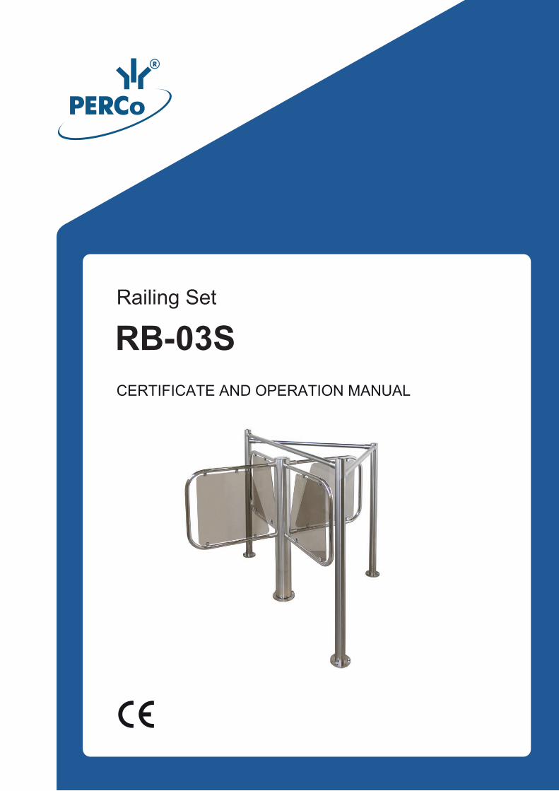
RB-03SRailing Set
Railing Set
RB-03S
Certificate and Operation Manual
CONTENTS
1 GENERAL DATA.........................................................................................................3
2 TECHNICAL SPECIFICATIONS .................................................................................4
3 DELIVERY SET...........................................................................................................5
3.1 Standard delivery set.............................................................................................5
3.2 Optional equipment supplied on request ...............................................................5
4 BRIEF DESCRIPTION ................................................................................................6
5 SAFETY REQUIREMENTS.........................................................................................6
5.1 Installation safety...................................................................................................6
5.2 Safety during operation .........................................................................................6
6 INSTALLATION INSTRUCTIONS...............................................................................7
6.1 General Recommendations...................................................................................7
6.2 Installation tools.....................................................................................................7
6.3 Installation procedure ............................................................................................7
7 MAINTENANCE ..........................................................................................................9
8 PERCo WARRANTY.................................................................................................10
RB-03S Railing Set
Dear customers!
We thank You for choosing the product manufactured by PERCo. You have purchased the high quality product, which will be long lasting
in operation provided that installation and operation rules are observed.
1 GENERAL DATA The Certificate and operation manual for RB-03S Railing set (hereinafter referred to as the “Railing set”) contains data that is necessary for the most full usage of operating advantages of the turnstile as well as chapters on packaging, installation and maintenance.
Only qualified personnel, following the instructions of this Certificate and manual, must carry out installation and maintenance.
The guide barriers set is used as a part of the RTD-03S waist-high rotor turnstile (hereinafter referred to as the “Turnstile”) and is designed to limit its nonpassage area.
The railing set, in accordance with the resistance to environmental exposure, is compliant with GOST 15150-69, category U4 (artificially controlled climate conditions).
Operation of the railing set is allowed at ambient temperature between +1°C and +45°C and relative air humidity up to 70% at +27°C.
The railing set in the original package should be transported in closed freight containers or other closed type cargo transport units.
During storage and transportation the boxes should be stacked no more than 3 layers high.
Storage of the railing set is allowed in dry indoor facilities at the ambient air temperature from -40°С to +45°С and relative air humidity of up to 98% at +25°С.
The environment should be free of acid and alkali vapours and gases that cause corrosion.
After transportation or storage at temperatures below zero or at high air humidity, prior to installation the wicket gate must be kept in the original package for no less than 24 hours indoors under normal climate conditions (+18°C, humidity – 60%) prior to installation.
The railing set in the standard package is packed in the box that protects it from being damaged during transportation and storage.
Box dimensions (length × width × height) ...................................................... 136×37×22 cm
On the box marked with.
Attention! The completeness of the delivery set should be verified right upon its receipt.
3
Certificate and Operation Manual
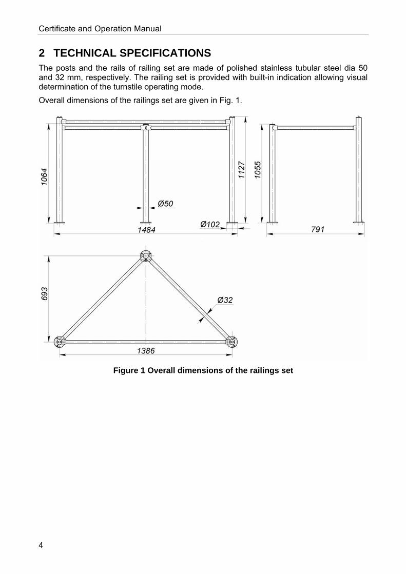
2 TECHNICAL SPECIFICATIONS The posts and the rails of railing set are made of polished stainless tubular steel dia 50 and 32 mm, respectively. The railing set is provided with built-in indication allowing visual determination of the turnstile operating mode.
Overall dimensions of the railings set are given in Fig. 1.
Figure 1 Overall dimensions of the railings set
4
RB-03S Railing Set
3 DELIVERY SET
3.1 Standard delivery set Basic equipment:
Centre post..................................................................................................................1
Indication post right .................................................................................................... .1 Indication post left ...................................................................................................... .1 Indication cable ...........................................................................................................1 Centre rail....................................................................................................................1 Rail ..............................................................................................................................2
Operational documentation: Certificate and operation manual.................................................................................1
Installation tools: Mounting screw M8×25 ...............................................................................................6
Hex-nut wrench S=1.5.................................................................................................1 Hex-nut wrench S=4....................................................................................................1
Package: Box ..............................................................................................................................1
3.2 Optional equipment supplied on request Anchor SORMAT PFG IH 10.......................................................................................9 Bolt M10×60 12X18H10T, DIN7984 A2.......................................................................9 Hex-nut wrench S=5....................................................................................................1
5
Certificate and Operation Manual
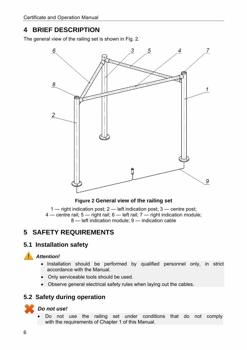
4 BRIEF DESCRIPTION The general view of the railing set is shown in Fig. 2.
Figure 2 General view of the railing set
1 — right indication post; 2 — left indication post; 3 — centre post; 4 — centre rail; 5 — right rail; 6 — left rail; 7 — right indication module;
8 — left indication module; 9 — indication cable
5 SAFETY REQUIREMENTS
5.1 Installation safety
Attention! Installation should be performed by qualified personnel only, in strict
accordance with the Manual.
Only serviceable tools should be used.
Observe general electrical safety rules when laying out the cables.
5.2 Safety during operation
Do not use! Do not use the railing set under conditions that do not comply
with the requirements of Chapter 1 of this Manual.
6
RB-03S Railing Set
6 INSTALLATION INSTRUCTIONS
6.1 General Recommendations
It is recommended to mount the railing set on steady and level concrete (grade 400 or higher, strength
group V22.5), stone or similar foundations at least 150 mm thick; to level the foundation so that the anchoring points of the posts lie in the same
plane; to apply reinforcing elements (300×300×300 mm) for installation on less steady
foundation; to mark the mounting holes according to the enclosed installation instructions
(see Fig.3); to control the vertical position of the posts during installation.
All positions are marked as per Fig. 4. Recommendations for preparation of mounting holes for installation of the posts are given for the "SORMAT" anchor bolts for steady concretes (see Table 1).
Table 1
Anchor bolt size, mm Drill diameter, mm Drilling depth, mm
PFG IH-8 16 60
6.2 Installation tools
1.2–1.5 kW hammer drill; Ø16 mm hard-alloyed drill for anchor bolts; Hex-nut wrench S=1.5; Hex-nut wrench S=4; Hex-nut wrench S=5; Hex-nut wrench S=7; Plumb - line and level; Measuring tape 3 m.
6.3 Installation procedure
Note! The manufacturer shall not be liable for any damage caused in the result of improper installation and declines any claims arising thereof in case if the installation is not in compliance with the instructions provided in this Certificate and manual
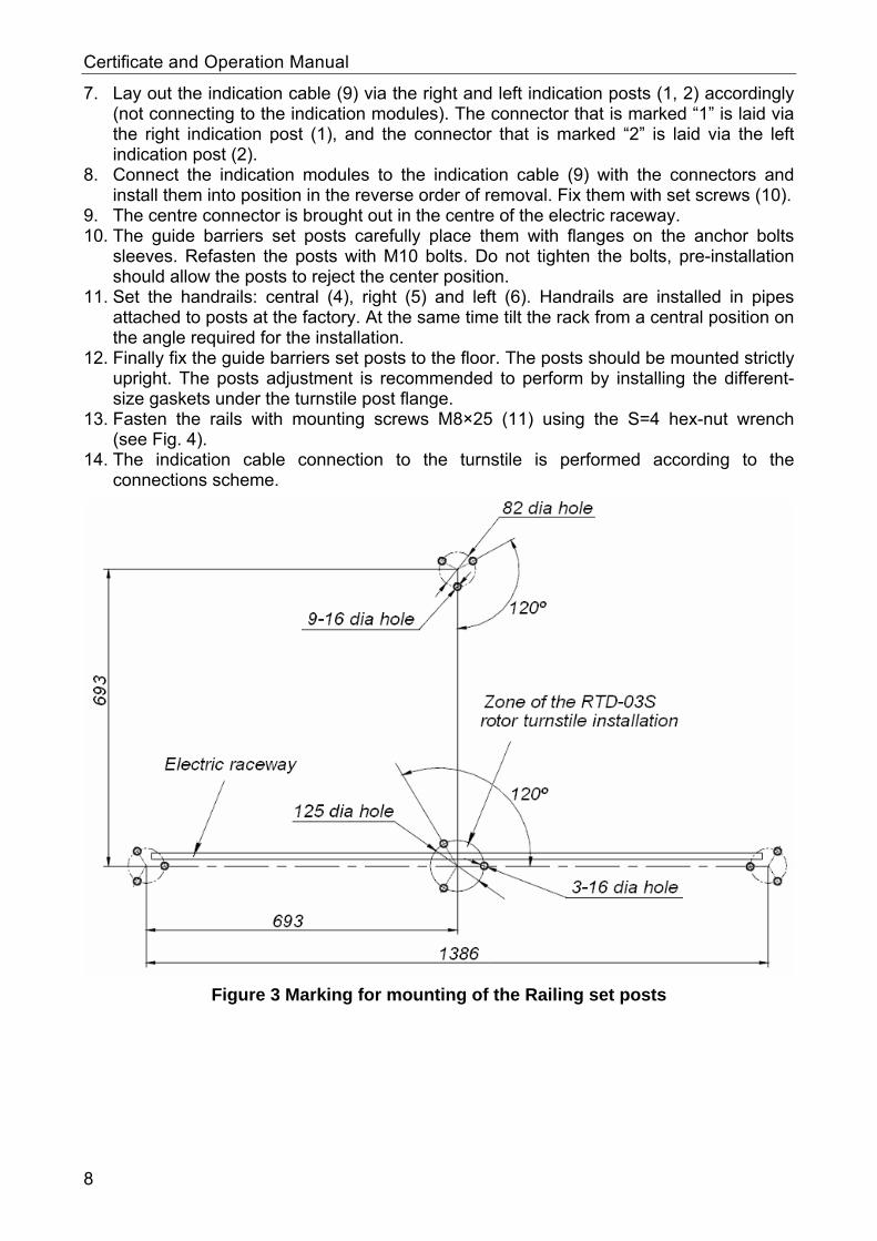
1. Unpack the railing set, check the completeness as per Chapter 3 of this Manual. 2. Study the Certificate and manual carefully prior to the installation. 3. Mark out the holes for the anchor bolts for the guide barriers post installation as shown
in Fig. 3. 4. Drill the holes for the indication cable and PFG IH 10 anchor bolts for the posts
mounting in the floor. 5. Insert the anchor bolts sleeves into the holes so that they do not stick out above the
floor surface. 6. Unpack the guide barriers set posts from the shipping box. Using the hex-nut wrench
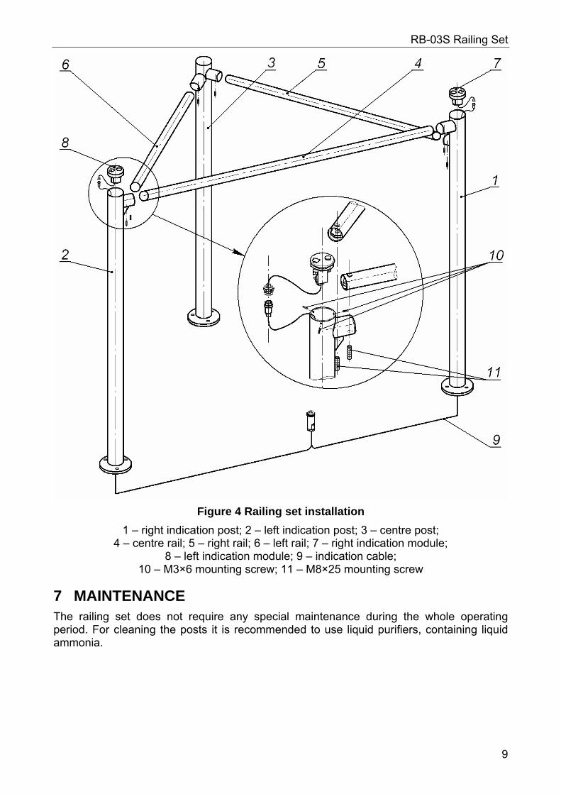
S=1.5 unscrew the set screws (10) (see Fig. 4) and remove the indication modules (7 and 8) from the posts.
7
Certificate and Operation Manual
7. Lay out the indication cable (9) via the right and left indication posts (1, 2) accordingly (not connecting to the indication modules). The connector that is marked “1” is laid via the right indication post (1), and the connector that is marked “2” is laid via the left indication post (2).
8. Connect the indication modules to the indication cable (9) with the connectors and install them into position in the reverse order of removal. Fix them with set screws (10).
9. The centre connector is brought out in the centre of the electric raceway. 10. The guide barriers set posts carefully place them with flanges on the anchor bolts
sleeves. Refasten the posts with M10 bolts. Do not tighten the bolts, pre-installation should allow the posts to reject the center position.
11. Set the handrails: central (4), right (5) and left (6). Handrails are installed in pipes attached to posts at the factory. At the same time tilt the rack from a central position on the angle required for the installation.
12. Finally fix the guide barriers set posts to the floor. The posts should be mounted strictly upright. The posts adjustment is recommended to perform by installing the different-size gaskets under the turnstile post flange.
13. Fasten the rails with mounting screws М8×25 (11) using the S=4 hex-nut wrench (see Fig. 4).
14. The indication cable connection to the turnstile is performed according to the connections scheme.
Figure 3 Marking for mounting of the Railing set posts
8
RB-03S Railing Set
Figure 4 Railing set installation
1 – right indication post; 2 – left indication post; 3 – centre post; 4 – centre rail; 5 – right rail; 6 – left rail; 7 – right indication module;
8 – left indication module; 9 – indication cable; 10 – М3×6 mounting screw; 11 – M8×25 mounting screw
7 MAINTENANCE The railing set does not require any special maintenance during the whole operating period. For cleaning the posts it is recommended to use liquid purifiers, containing liquid ammonia.
9
Certificate and Operation Manual
8 PERCO WARRANTY PERCo (the Manufacturer) warrants that the RB-03S railing set (the Product) complies with applicable statutory safety and electromagnetic requirements provided that the storage, installation and operation instructions are observed.
The warranty period is 12 (twelve) months commencing from the date of sale.
Should there be no date of sale on the warranty card, the warranty period shall commence from the date of manufacture specified in the Certificate and on the Product label.
In the post-warranty period the replacement parts/components are warranted to be free from defects in material or workmanship for a period of 3 (three) months from the date of shipment of the repaired/replaced Product to the Customer.
All claims with regard to quantity, completeness and defects to appearance of the Product delivered are accepted by the Manufacturer in writing within no more than 5 (five) working days after the products are received by the Customer. In case of failure to meet the abovementioned deadline no claims are accepted.
The Warranty does not cover: products, parts and components with:
- external mechanical damages resulting in the Product’s fault; - defects resulting from Customer's improper testing, operation, installation,
maintenance, modification, alteration, or adjustment; - damages due to force majeure circumstances (natural disasters, vandalism etc.)
or defects as a result of external circumstances (power surges, electric discharge, etc);
fuses, accumulators, galvanic elements and other components, replacement of which is performed by the Customer in accordance with the Product’s in-line documentation.
To the maximum extent permitted by the acting law, the Manufacturer does not incur a liability for any direct or indirect losses of the Customer, including but not limited to loss of profit or data, losses caused by idle period, missed profit, and etc related to use or impossibility to use products and software, including possible software errors and failures.
Within the warranty period the products are repaired free of charge at the Manufacturer’s site. The Manufacturer reserves the right to repair failed product or replace it with an operational one. Time of repair is specified at the moment the Product is accepted for repair. Transportation cost to and back from the place of repair shall be borne by the Customer.
In order to shorten the repair time the Customer must inform the Manufacturer’s Technical Support Department (the TSD) of the problem with the Product’s operation and/or about the origin of the fault by submitting a filled-in Technical Support Form by e-mail, fax or via the Manufacturer’s website or communicate directly a specialist of the TSD.
The Manufacturer reserves the right not to accept the Product for repair from the Customer who failed to submit the Technical Support Form.
The Manufacturer’s warranty obligations don’t cover attendance by the experts of a Customer and maintenance of any Product on site
If in the course of the examination taken by the Manufacturer of the Product or its parts/components believed to be faulty, no faults have been detected, the Customer is responsible for compensation of the Manufacturer’s expenses related to the examination.
10
RB-03S Railing Set
Apart from the warranties mentioned above the Manufacturer does not provide any other warranties with regard to compatibility of a Product purchased with software or products produced by other manufacturers as well as any warranties that this Product will fit for the purposes not stipulated in the Product’s in-line documentation.
The warranty does not provide for any claims with regard to the technical specifications of the Product in case they are in compliance with those stated by the Manufacturer. The Manufacturer does not guarantee that the Product purchased will meet Customer’s requirements and expectations.
PLEASE NOTE THAT PERCo PRODUCES TECHNICALLY SOPHISTICATED PRODUCTS THAT, IF NOT FAULTY, CANNOT BE RETURNED BACK IF BY SOME REASON THE CUSTOMER DEEMS THEM UNSATISFACTORY
The PERCo RB-03S railing set is in conformity with the essential requirements of the EU’s Machinery, Low-Voltage and EMC Directives and
carries the CE marking accordingly.
11

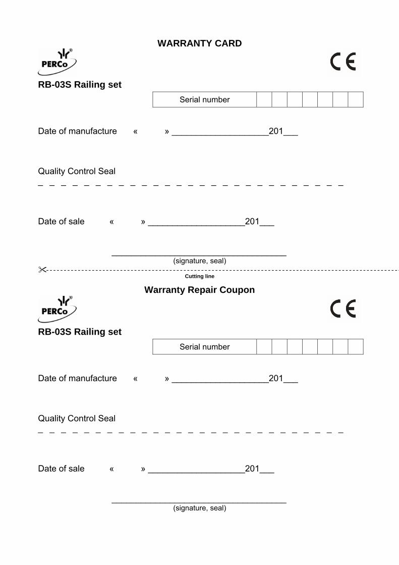
WARRANTY CARD
RB-03S Railing set
Serial number Date of manufacture « » ____________________201___ Quality Control Seal _ _ _ _ _ _ _ _ _ _ _ _ _ _ _ _ _ _ _ _ _ _ _ _ _ _ _
Date of sale « » ____________________201___ ____________________________________
(signature, seal)
Cutting line
Warranty Repair Coupon
RB-03S Railing set
Serial number Date of manufacture « » ____________________201___ Quality Control Seal _ _ _ _ _ _ _ _ _ _ _ _ _ _ _ _ _ _ _ _ _ _ _ _ _ _ _
Date of sale « » ____________________201___ ____________________________________
(signature, seal)


PERCo
Polytechnicheskaya str., 4, block 2 194021, Saint Petersburg
Russia
Tel: +7 812 247 04 64
E-mail: [email protected] [email protected]
www.perco.com

www.perco.com