radio engineering microwave radio 11-ghz systems...
TRANSCRIPT

BELL SYSTEM PRACTICES
Plant Series
SECTION 940-384-103
Issue 1, February 1970
AT&TCo Standard ,
CONTENTS
1. GENERAL . . . . . . . .
2. TRANSMISSION CHARACTERISTICS
3. FREQUENCY PLAN . . . . .
A. General . . . . . . .
B. Modified Plan . . . . .
C. Staggered Plan . . . . .
4. TRANSMITTER . . . . . .
RADIO ENGINEERING
MICROWAVE RADIO
11-GHZ SYSTEMS
4
A.●
B.
c.
D.
E.
F.
General . . . . . . .
Transmitter Baseband Amplifier
TL-2
PAGE
,..
. .
. . .
. . .
. . .
. . .
. . .
. . .
. .
Klystrons and Associated Equipment .
Transmitter Isolator . . . . . .
Directional Coupler, Power Menitor,
Frequency Monitor, and Waveguide
Switch . . . . . . . . . . .
Channel Combining Network . . .
5. RECEIVER . . ...0.. . . .
A. General . . . . . . . . . .
B. RF Components . . . . . . . .
C. IF and Baseband Unit . . . . .
6. ANTENNAS AND WAVEGUIDE SYSTEMS
A. General . . . . . . . . . .
2
2
2
2
4
4
5
5
5
5
9
9
12
12
12
12
14
17
17
7.
8.
9.
10.
11.
12.
13.
CONTENTS PAGE
B. Parabolic Antennas and Associated
Filters . . . . . . . . . . .20
C. Waveguide and RF Component Losses21. . . . . . . . . . . . .
CALCULATION OF RECEIVED CARRIER
POWER . . . . . . . . . . . .21
TRANSMISSION PERFORMANCE . . . 22
A. Noise . . . . . . . . . ..22
B. Overload . . . . . . . . ..26
C. linearity and Delay . . . . . . 26
D. Television . . . . . . . . ..26
E. Noise Obiective . . . . . . . 29
DIVERSITY TECHNIQUES . . . . . . 30
A. Definitions . . . . . . . . . 30
B. General . . . . . . . . ..30
C. Bistable Switch . . . . . . . . 3°
D. Revertive Switch . . . . . . . 30
ORDER WIRE AND ALARM . . . . . 31
POWER REQUIREMENTS . . . . . . 31
CONSIDERATIONS-CONJOIN OF TL-2 AND
ANOTHER 11-GHZ RADIO SYSTEM IN MID
HOP . . . . . . . . . . . . .32
EQUIPMENT DESIGN . . . . . . . 33 *
@ American Telephone and Telegraph Company, 19’70Printed in U.S.A. Page 1

. . ‘-q
SECTION 940-384-103
CONTENTS PAGE*
14. PORTABLE EQUIPMENT . . . . . . 33
TABLE A
TL-2 RADIO CHANNEL CAPACITY
15. REFERENCES . . . . . . . . . . 34
1. GENERAL
1.01 The TL-2 radio is a frequency-modulated(FM) microwave radio system designed to
provide a highly reliable message transmissionmedium and a television capability. The TL-2features compact design, high reliability, simplifiedmaintenance, full-float battery operation, low cost,and is completely transistorized except for thetransmitter and receiver klystrons.
1.02 The TL2, in crossband diversity with TM-1,is designed to yield higher reliability, carry
heavier message loads, give better noise performance,and furnish television capability in the short-haulfield. It is intended to provide short-haul radiochannels (1) in difficult geographical situations, (2)wher’; cable or wire facilities would not proveeconomical, (3) where open wire requires replacement,(4) where existing cable routes are being exhausted,and (5) as spurs leading from heavy route microwaveor cable systems. System performance objectivesand possible problem areas are discussed in thispractice to make engineering of the TL2 systemeasier.
2. TRANSMISSION CHARACTERISTICS
2.01 The TL2 radio channel design capacity isbased on a received signal level no lower
than – 42 dBm and a 10 hop noise objective of 35dBmcO (29 dBaO). A received signal of –45 dBmincludes a 3-dB maintenance margin to allow forminor imperfections in system alignment and systemdegradation with age. Table A lists the TL2 radiochannel capacity.
2.02 The TL2 system channel capacity is basedon length, noise, and economics and is capable
of accommodating more than 600 channels or morethan ten hops dependent upon the particularapplication and the corresponding trunk noise. Tomeet the general objectives set forth for thesystem, transmission characteristics as listed inTable B were established.
TYPE OF LOAD I MESSAGE NUMBERCIRCUITS OF HOPS
L Carrier 600 10
ON Carrier 96 10
N Carrier 48 10
Network television * 6
Educational television * 10
* One television channel
3. FREQUENCY PLAN
A. General
3.o1 The TL2 radiofrequency band
per radio channel.
system uses the 1OOO-MHZbetween 10.7 and 11.7 GHz.
This band ‘is di~ded into 24 channels with 40-MHzseparation between midchannel frequencies. In .general, the frequency assignments and channel .numbers are identical to those used in TJ andTL1 radio systems.
3.02 Both the TL2 and TM-1 systems normallyemploy a four-frequency plan using each RF
frequency only once at a repeater. In any onedirection of transmission, alternate channels having80-MHz separation are used. To provide adequateseparation between transmitters and receivers atany one station, the upper half of the frequencyband is allocated to transmitting when the lowerhalf is receiving. An adjacent station will betransmitting in the lower half of the band andreceiving in the upper half. The upper and lowerhalves of the frequency band are separated by a90-MHz guard band.
3.03 Polarization of adjacent channels alternatesbetween vertical and horizontal to provide
maximum frequency separation between channelsof the same polarity. This method provides 16@MHzseparation between adjacent channels of the samepolarization. Overreach interference is reduced byalternating horizontal and vertical polarization of agiven frequency. A frequency having a horizontalpolarization in one hop will occur again two hopsaway but will be vertically polarized.
Page 2

1SS 1, SECTION 940-384-103
TABLE B
11-2 TRANSMISSION CHARACTERISTICS
GENERAL
RF frequency rangeFrequency plan #1
Number of channelsFrequency plan #2
Number of channelsPre-emphasis
MessageVideo
Power requirementsT/R (watts)AC operationReserveDC operation
Ambient temperature rangeMaximum hops per alarm sectionRelay rack
TRANSMITTER
Output power (minimum)Peak deviationFrequency stabilityInput impedance
Message and video
- ON/N carrier optionSine-wave level in
● for reference deviation (*4 MHz)Video level in
for reference deviation (*4 MHz)
RECEIVER
InputNoise figureFade margin (minimum)Intermediate frequency (IF)IF bandwidth (0.5 dB or better)Effective noise bandwidth (3.0 dB )Baseband widthOutput impedance
Message and video
OhT/N carrier optionSine-wave level out
for reference deviation (*4 MHz)Video level out
for reference deviation (*4 MHz )Differential gain
(six hops of TV)Differential phase
(six hops of TV)
10.7 to 11.7 GHzModified plan24Staggered plan24
9 dB7 dB
1501 phase — 120 voltsBattery—24 volts+20° to +120”F107 or 9 feet by 23 inches
+20 dBm (0.1 watt)&5 MHz30.05 percent (*5 MHz)
75 ohms unbalanced124 ohms balanced135 ohms balanced
–14 dBm
–16.5 dBV
—42 dBm10.5 dB typical30 dB70 MHz16 MHz20 MHz10 Hz to 6 MHz
75 ohms unbalanced124 ohms balanced135 ohms balanced+6,5 dBm
+4 dBV
1.0 dB
1.OO
Page 3

SECTION 940-384-103
B. Modified Plan
*3.o4 In order to implement the preceding general
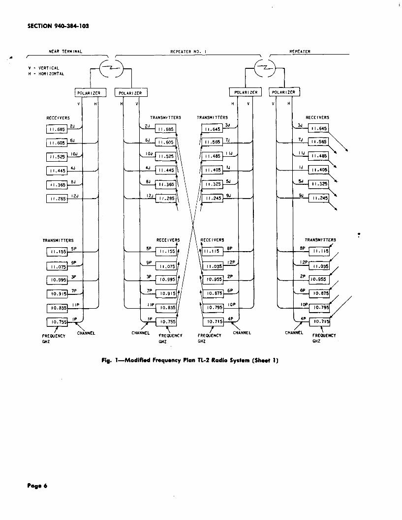
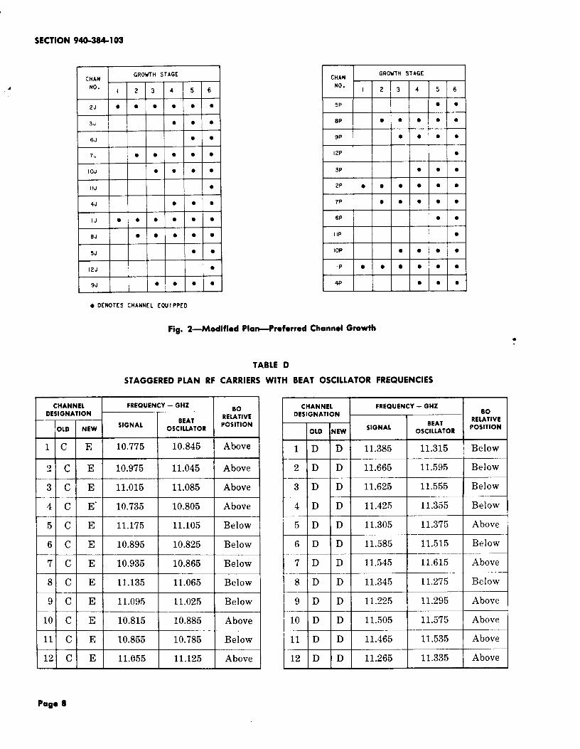
requirements, a channel assignment andfrequency allocation plan has been established. Forthis plan (see Table C), the 12 low-frequencychannels are designated group A, or more recently,P. The 12 high-frequency channels are group B,or J. An example of this plan over four hops isshown in Fig. 1. Notice that channels (six maximum)transmitting north or east have odd numbers andchannels (six maximum) transmitting south or westhave even numbers. Also, all channels in onedirection on a specific hop are designated P, inthe opposite direction J, and on adjacent hops,reversed. The growth plan for TL2 is shown inFig. 2.
C. Staggered Plan
3.o5 The staggered plan is a special plan usedfor intersecting TL-2 routes. This plan
locates the radio channels half way between thenormal frequencies and shifts all the P frequencies
20 MHz higher and the J frequencies 20 MHzlower. It does not increase the available numberof channels on a given radio hop since a 160-MHzminimum frequency spacing must be maintainedbetween channel separating networks in a givenwaveguide run. The 24 channels and receiver beatoscillator frequencies for the staggered plan arelisted in Table D.
3.o6 Mixing frequency plans is discouraged sinceit reduces the ultimate route capacity and
may lead to interpanel frequency interference frombeating oscillators. The frequency of the beatoscillator is kept within the assigned common carrierband, but may be above or below the frequencyof the incoming RF carrier. The position of aparticular beat oscillator is dictated by interferenceconsiderations. Before a frequency plan is selected,consult Sections 940-330-102” and 940-330-110 forinformation concerning microwave interference.
● This section may not be available. Consult thelatest numerical index.
●
TABLE C
MODIFIED PLAN RF CARRIERS WITH BEAT OSCILLATOR FREQUENCIES
CHANNEL FREQUENCY — GHZDESIGNATION Bo
BEATRELATIVE
I OLD \NEW “GNAL OSCILLATORPOSITION
1!1A P 10.755 10.825 AboveI
I 2AP I 10.955 I 11.025 I Above I1 I 1 I ,
3 A P 10.995 11.065 AboveI I I I I
41 AlP\ 10.715 10.785 Above
5 A P 11.155 11.085 Below
6 A P 10.875 10.805 Below1 1 ,
7 A P 10.915 10.845 Below
I I I
12 A P 11.035 11.105 Above
1 1 I 1 I
I l]BIJ 11.405 11.335 Below
2 B J 11.685 11.615 Below
3 B J 11.645 11.575 Below
4 B J 11.445 11.375 Below
5 B J 11.325 11.255 Below
6 B J 11.605 11.535 Below
7 B J 11.565 11.495 BelowI I 1
8 B J 11.365 i~I I t r 1
t 91BIJ 11.245 11.315 AboveI I I I I
10 B J 11.525 11.595 AboveI I 1 [ I
11 B J 11.485 11.555 Above1 i I 1 1
12 B J I 11.285 11.355 Above
Page 4

1SS 1, SECTION 940-384-103
4. TRANSMITTER
A. General
4.o1 The TL-2 radio transmitter (Fig. 3)frequency-modulates a baseband signal onto
a microwave carrier in the 11-GHz common-carrierfrequency band. The baseband signal is amplifiedby the transmitter baseband amplifier and appliedto the repeller of the transmitter klystron. Theklystron then produces a frequency-modulated RF
signal which is passed through an isolator to adoubledirectional coupler. The directional couplerprovides access for both frequency and powermonitoring of the signal. The through arm of thedirectional coupler directs the RF signal to amanually operated waveguide switch which isprovided to isolate the transmitter RF output fromthe antenna system during maintenance of the radiotransmitter. From the waveguide switch, the signalpasses through a combining network to the antennasystem.
B. Transmitter Baseband Amplifier
4.02 The transmitter baseband amplifier is a partof the transmitter control and baseband
-amplifier unit. The transmitter baseband amplifier
~ is designed to be able to modulate the transmitterto a +4 MHz peak-to-peak deviation with a – 14dBm =ine-wave test signal. The output of thebaseband amplifier is impressed on the repeller ofthe transmitter klystron. The transmitter basebandamplifier gain is adjustable over a range of +3.5
dB to compensate for klystron repeller sensitivityvariations.
4.o3 In order to provide a transmitter controland baseband amplifier unit which would be
interchangeable for both TL-2 and TM-1 and toprovide design improvements, a new unit wasinitiated. The resulting redesign, coded J99302J2List 4, provides a single interchangeable unit whichis physically and electrically suitable for both TM-1
and TL2. However, transmission performance ofthe original unit, J99296J-1, is still good.
4.04 The new transmitter baseband amplifier isflat to within +0.1 dB from 50 Hz to 10
MHz. Amplifier lin~arity is improved. Thedifferential gain and phase are negligible. The
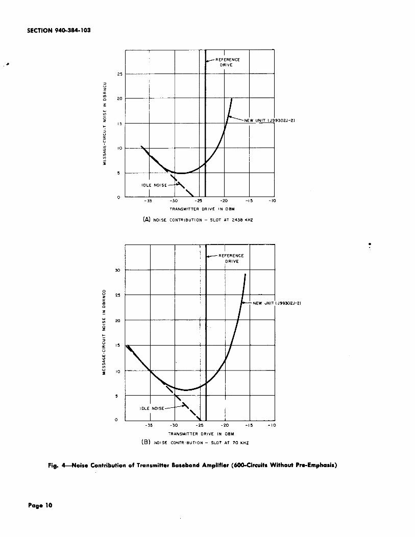
technique of noise loading, applied to control units,allows an evaluation of performance with regardto their contribution to overall system performance.Figure 4 shows the noise loading performance fortypical units of new design at 70 kHz and 2438kHz. Unit-to-unit variations and changes causedby extremes of temperature are considerably lessin the new unit.
C. Klystrons and Associated Equipment
4.o5 The klystron for the TL-2 radio system,used in both transmitter and receiver, is a
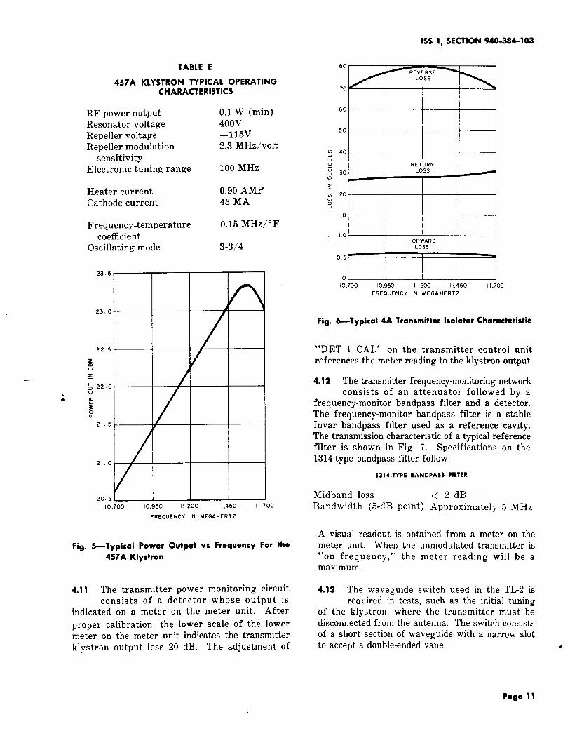
WE457A reflex klystron. Specifications for thistube are listed in Table E. The estimated averagelife of a 457A klystron is 40,000 hours and thewarranty period is 10,000 hours. A typical poweroutput versus frequency plot for the 457A is shownin Fig. 5.
4.o6 The frequency stability of the TL2 transmitteris obtained in part by carefully controlling
the temperature of the klystron. The radioequipment must operate in an environment ofoutside temperatures ranging from – 4&F to + 1200F.Over a 3-month maintenance interval, the rangeof ambient temperature is not likely to exceed100’F. To meet the +0.05 percent frequency accuracyfor TL2, the klystron temperature must be heldto -+*F. Klystron voltages must also be closelyregulated.
4.07 A special feature of the 457A klystron is aclosely controlled temperature coefficient
which does not exceed +0.15 MHz per degreeFahrenheit. This feature,–in conjunction with thevapor-phase cooling system, makes the frequencyrelatively independent of ambient temperature.
4.08 A klystron protection circuit is available forTL2 radio systems. The klystron protection
circuit consists of a normally open temperature-operatedswitch in series with a current-limiting resistorconnected from the 6-ampere inverter fuse to ground.Should the boiler temperature reach 265”F, theswitch will close, blowing the inverter fuse. Thisremoves all operating voltages from both klystrons.Without the thermostat action, both klystrons wouldbe destroyed within minutes; thus, the blowing ofthe fuse does not add significantly to the radiochannel outage time for this particular trouble ~condition.
Page 5
SECTION 940-3S4-103
NEAR TERMINAL REPEATER NO. I REPCATER
A / \ / \ /
H- HORIZONTAL I II
I POLARIZER I ]U AR I—
v $Pc
v
ARIZ
H
J-
Hv H
—
.
—
—
—
v
TRANSMITTERS
2J11.685
6J
I O.J
4J
12J
TRANSUI TTERS
w
RECEIVERSRCCC I VCRS
l-Txw--
:=~\
7J11.585
I IJ11.485
EiEw-- / ,,.565 7J
F
r
11.465 “J
r
11.405 ‘J
P
11.325 a
F
-’
I vRECf lVfRS /\ RCCE 1VfRS lRANSMI TTERS
-/ “
TRANSMITTERS
\bYI---==w -t-+=$ / .
.
—
—
—
—
L*\10.9552P
-wa’,
%33P
10.995
7P10.915
I 1P10.835
1P10.755
6P10.875
s/‘w 10.795
EEv- \tI!EF
7=3,y~NNEL
FREWENCY
-CHANNEI
1
f
J
FR[W[NCY
GHZ
CHANNEL \fREWENCY
GHZ
CHANNELFRKiJENCY
GHzGHZ
Fig. l—Modifiod Frequency Plan 11-2 Radio System (Shoot

1SS 1, SECTION 940-384-103
I L./ c--l-PI
I I
5m
v
ARIZ
H
—
J LRIZER I AR I Z[R I
IH 1vHv
—
TRANSMITTERS TRANSMITTERS
,,.645 3’
P
P
11.565
&
RfCEIVERS
q11.645
RECCIVERS
‘J==- -
-q
11.605
k
11.5251 IJ
11.485
rI 11.405 “
F
5J11.325
P
9’11.245
i=
8J11.365
12J11.285 \-7
I 2J11.285 .
L-RECf IVERS
llIw-
L
f2P11.035
\ 10.9S5 2P
RFCE I VERS
d
d
9P
d
11.075
3P10.995
/
TRANSMITTERS
q11.115
TRANSMITTERS
.%=●
““m,0.995 3P
10.915 7P
&
I 1P
&
10.7551P
—
—
—
—
—
J 2P11.035
—
+2El—
,“AN*FREW[NCY
GHZ
CHANNEL \ /FREWCNCY FREIWENCY
CHANNEL
GHZ GHZ
/FREQUENCY
CHANNEL
GHZ
Fig. l—Modified Frequency Plan TL-2 Radio System (Sheet 2)
4
SECTION 940-3S4-103
CHANGROWTH STAGE
NO.I 2 3 4 5 6
2J ● ● ● ● ● ●
3J ● ● ●
6J ● ●
7J 9 ● ● ● ●
10J ● ● ● ●
I IJ ●
4J ● ● ●
IJ ● ● ● ● ● ●
OJ ● ● ● ● ●
5J ● ●
12J b
9J ● ● ● ●
● CKNOTES CHANNEL [WI PPCD
Fig. 2—Modified PlaAreferred
TABLE D
5P II II IOI0
8P ● ● ● ● ●
9P ● ● ● ●
I 2P ●
3P ● ● ●
2P ● ● ● ● ● ●
7P ● ● ● ● ●
6P ● ●
I 1P ●
IOP ● ● ● ●
I I I 1 I 1
1P ● ● ● ● ● ●
4P ● ● ●
●
STAGGERED PLAN RF CARRIERS WITH BEAT OSCILLATOR FREQUENCIES
CHANNEL FREQUENCY - GHZDESIGNATION
00
BEATRELATIVE
OLD NEWSIGNAL
OSCILLATORPOSITION
I
1 c E 10.775 10.845 / Aboven ,
Iii2CE 10.975 11.045 Above
I 3CE I 11.015 I 11.085 I Above
I 4CE’ 10.735 I 10.805 I Above
I 51CI E I 11.175 I 11.105 I Below
I 6CE I 10.895 I 10.825 I Below
I 7 I C I E I 10.935 I 10.865 I Below
I 8CE I 11.135 I 11.065 I Below
t
9 c E 11.095 11.025 Below—
10 c E 10.815 10.885 Above
11 c E 10.855 10.785 Below
12 c E 11.055 11.125 Above
CHANNEL FREQUENCY - GHZDESIGNATION BO
BEATRELATIVE
OLD NEWSIGNAL
OSCILLATORPOSITION
1 D D 11.385 11.315 1 Below
2 D D 11.665 11.595 Below
3 D D 11.625 11.555 Below
4 D D 11.425 11.355 Below
5 D D 11.305 11.375 Above
6 D D 11.585 11.515 Below
7 D D 11.545 11.615 Above
8 D D 11.345 11.275 Below
9 D D 11.225 11.295 Above
10 D D 11.505 11.575 Above
11 D D 11.465 11.535 Above——
12 D D 11.265 11.335 Above

1SS 1, SECTION 940-384-103
●
TO f–ANTENNA
POW R
NON I TOR I
I
SIGNAL1
INPUT OOUBL[
fROM ISOLATOR DIRECTIONAL UAVfGU I Df CWBINING
MULTI PLEX COUPLER WITCH NEWORK
[OUIPMENT
BAS[9AND TRANSMITTER
—
AMPLIFIER KLYSTRON
Q
ATTENUATOR
II I
FREC4KNCYAND POVER
NON I TOR
hMETER
UNIT
D. Transmitter Isolator
FREOUENCY
NON I TOR
8ANOPASS
+
TO OTHER
CONBINING
OR
DETECTOR SEPARATING
NETWORKS
+TO FREWENCY
NON I TOR
Fig. 3-Block Diagram-TL-2 Transmitter
4.o9 A high reverse-loss isolator is used as animpedance match between the klystron and
the waveguide and antenna. Typical performance
characteristics for the dielectric-loaded full-heightE-plane isolator used in the TL-2 are shown inFig. 6. Specifications for the 4A isolator follow.
4A ISOLATOR
Forward loss < 0.9 dB
Reverse loss < 55.0 dB
E. Directional Coupler, Power Monitor, Frequency
Monitor, and Waveguide Switch
4.10 In the TL2 radio system the output of theisolator is connected to a double-directional
coupler. The directional coupler provides two portshaving outputs which are 20 dB down, relative tothe main transmission path. One port channelsRF energy which is used to measure transmitterpower output and the other feeds a waveguidenetwork which monitors transmitter frequency.
Page 9
25
20
15
10
5
0
30
25
20
Is
10
5
0
-REFERENCE
DRIvE
NE W uNIT [J$
*
\ ,
IDLE NOISE—
-35 -30 -25 -m -15 -10
TRANSMITTER DRIvE IN OEM
(~ NOISE CONTRIBUTION - SLOT AT 2438 KHZ
- REFERENCE
DRIVE
IOLE NOISE—
\
- 3s -30 -25 -20 -15 -lo
TRANSMITTER ORIVE IN OEM
(B) NOISE CONTRITION - SLOT AT 70 KHZ
9302J-2)
J99302J-2)
Fig. -Noise Contribution of Transmitter Baseband Amplifier (600-Circuits Without Pre-Emphasis)
Page 10
1SS 1, SECTION 940-384-103
●
TABLE E
457A KLYSTRON TYPICAL OPERATINGCHARACTERISTICS
RF power output 0.1 W (rein)Resonator voltage 400VRepeller voltage –115VRepeller modulation 2.3 MHz/volt
sensitivityElectronic tuning range 100 MHz
Heater current 0.90 AMPCathode current 43 MA
Frequency-temperature 0.15 MHz/°Fcoefficient
Oscillating mode 3-3/4
23.5
23.0A
22.5 -
2nz—
g 22.00
e
~oa
21.5
21.0
205
I0,700 10,950 11,200 I 1,450 11,700
‘“——H—t—i‘“t__tttl
o~
10,700 Io,95c 11,200 I 1,450 I 1,700
FREOUENCY IN MEGAHERTZ
Fig. 6-Typical 4A Transmitter Isolator Characteristic
“DET 1 CAL” on the transmitter control unitreferences the meter reading to the klystron output.
4.12 The transmitter frequency-monitoring networkconsists of an attenuator followed by a
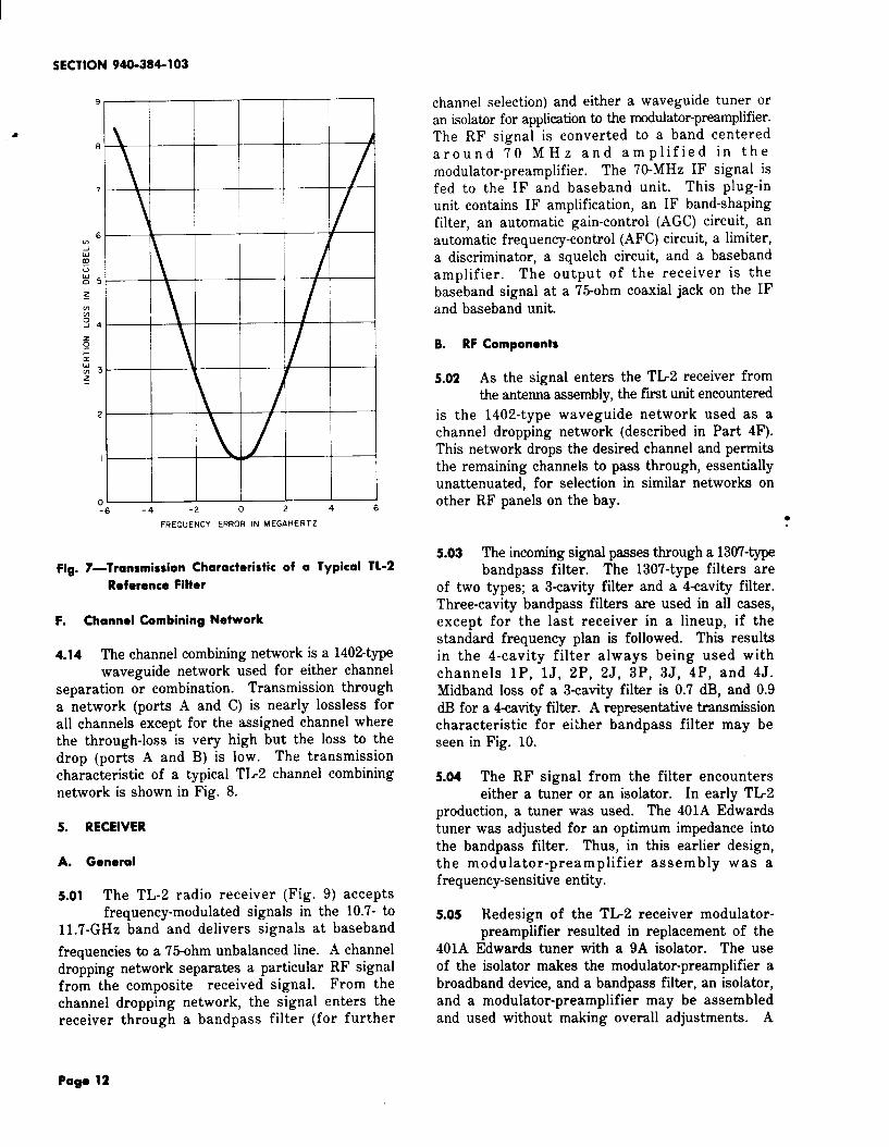
frequency-monitor bandpass filter and a detector.The frequency-monitor bandpass filter is a stableInvar bandpass filter used as a reference cavity.The transmission characteristic of a typical referencefilter is shown in Fig. 7. Specifications on the1314-type bandpass filter follow:
1314-TYPE BANDPASS FILTER
Midband loss <2dBBandwidth (5-dB point) Approximately 5 MHz
FREOUENCY IN MEGAHERTZ
A visual readout is obtained from a meter on theFig. 5-Typical Power Output vs Frequency For the meter unit. When the unmodulated transmitter is
457A Klystron “on frequency, ” the meter reading will be amaximum.
4.11 The transmitter power monitoring circuit 4.13 The waveguide switch used in the TL2 isconsists of a detector whose output is required in tests, such as the initial tuning
indicated on a meter on the meter unit. After of the klystron, where the transmitter must be
proper calibration, the lower scale of the lower disconnected from the antenna. The switch consists
meter on the meter unit indicates the transmitter of a short section of waveguide with a narrow slot
klystron output less 20 dB. The adjustment of to accept a double-ended vane. ●
Page 11
SECTION 940-384-103
.~-6 -4 -2 6
FREQuENCY ERROR IN MEGAHERTZ
Fig. 7—Transmission Characteristic of a Typical TL-2
Reference Filter
F. Channel Combining Network
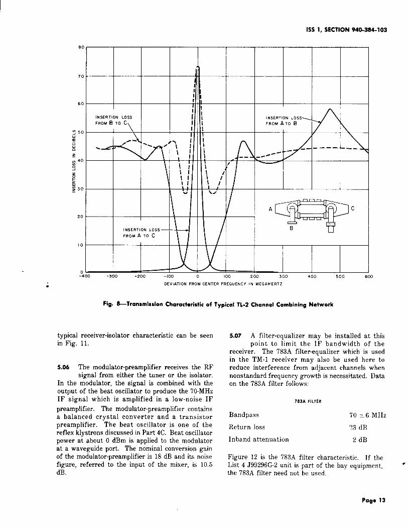
4.14 The channel combining network is a 1402-typewaveguide network used for either channel
separation or combination. Transmission througha network (ports A and C) is nearly lossless forall channels except for the assigned channel wherethe through-loss is very high but the loss to thedrop (ports A and B) is low. The transmissioncharacteristic of a typical TL2 channel combiningnetwork is shown in Fig. 8.
5. RECEIVER
A. General
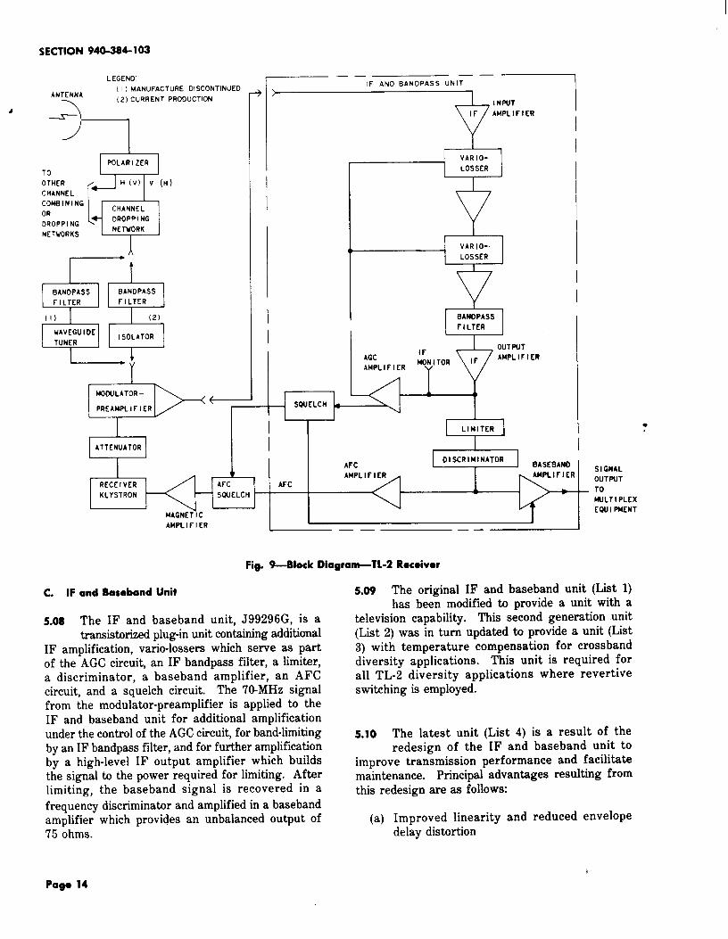
5.01 The TL-2 radio receiver (Fig. 9) acceptsfrequency-modulated signals in the 10.7- to
11.7-GHz band and delivers signals at baseband
frequencies to a 75-ohm unbalanced line. A channeldropping network separates a particular RF signalfrom the composite received signal. From thechannel dropping network, the signal enters thereceiver through a bandpass filter (for further
channel selection) and either a waveguide tuner oran isolator for application to the modulator-preamplifier.The RF signal is converted to a band centeredaround 70 MHz and amplified in themodulator-preamplifier. The 70-MHz IF signal isfed to the IF and baseband unit. This plug-inunit contains IF amplification, an IF band-shapingfilter, an automatic gain-control (AGC) circuit, anautomatic frequency-control (AFC) circuit, a limiter,a discriminator, a squelch circuit, and a basebandamplifier. The output of the receiver is thebaseband signal at a 75-ohm coaxial jack on the IFand baseband unit.
B. RF Components
5.o2 As the signal enters the TL2 receiver fromthe antenna assembly, the fmt unit encountered
is the 1402-type waveguide network used as achannel dropping network (described in Part 4F).This network drops the desired channel and permitsthe remaining channels to pass through, essentiallyunattenuated, for selection in similar networks onother RF panels on the bay.
●
5.o3 The incoming signal passes through a 1307-typebandpass filter. The 1307-type filters are
of two types; a 3-cavity filter and a 4-cavity filter.Three-cavity bandpass filters are used in all cases,except for the last receiver in a lineup, if thestandard frequency plan is followed. This resultsin the 4-cavity filter always being used withchannels 1P, lJ, 2P, 2J, 3P, 3J, 4P, and 4J.Midband loss of a 3-cavity filter is 0.7 dB, and 0.9dB for a 4-cavity filter. A representative transmissioncharacteristic for either bandpass filter may beseen in Fig. 10.
5.04 The RF signal from the filter encounterseither a tuner or an isolator. In early TL2
production, a tuner was used. The 401A Edwardstuner was adjusted for an optimum impedance intothe bandpass filter. Thus, in this earlier design,the modulator-preamplifier assembly was afrequency-sensitive entity.
5.o5 Redesign of the TL-2 receiver modulator-preamplifier resulted in replacement of the
401A Edwards tuner with a 9A isolator. The useof the isolator makes the modulator-preamplifier abroadband device, and a bandpass filter, an isolator,and a modulator-preamplifier may be assembledand used without making overall adjustments. A
Pago 12
1SS 1, SECTION 940-384-103
8C
7C
6C
20
10
n
?II
II !I I
INSERTION LOSS i \
FROM B TO C
I 1
//- 1
; II
; !1
:~ I
II
\; I\ /
I 1
INSERTION LOSS
FROM A TO C
INSERTION LOSS=
FROM ATO B
-_ -——— ,___
I
-400 -300 -200 -1oo 0 100 200 300 400 500 600
OEVIATION FROM CENTER FREQUENCY IN MEGAHERTZ●
Fig. &lransmission Characteristic af Typical TL.2 Channel Combining Network
typical receiver-isolator characteristic can be seenin Fig. 11.
5.06 The modulator-preamplifier receives the RFsignal from either the tuner or the isolator.
In the modulator, the signal is combined with theoutput of the beat oscillator to produce the 70-MHzIF signal which is amplified in a low-noise IF
preamplifier. The modulator-preamplifier containsa balanced crystal converter and a transistorpreamplifier. The beat oscillator is one of thereflex klystrons discussed in Part 4C. Beat oscillatorpower at about O dBm is applied to the modulatorat a waveguide port. The nominal conversion gainof the modulator-preamplifier is 18 dB and its noisefigure, referred to the input of the mixer, is 10.5dB.
5.07 A filter-equalizer may be installed at thispoint to limit the IF bandwidth of the
receiver. The 783A filter-equalizer which is usedin the TM-1 receiver may also be used here toreduce interference from adjacent channels whennonstandard frequency growth is necessitated. Dataon the 783A filter follows:
783A FILTER
Bandpass 70 =6 MHz
Return loss ?3 dB
Inband attenuation 2 dB
Figure 12 is the 783A filter characteristic. If theList 4 J99296G-2 unit is part of the bay equipment, rthe 783A filter need not be used.
Page 13
SECTION 940-284-103
LEGENCI
ANTENNA( I ) MANuFACTURE DISCONTINUED
(2) CURRENT PRODUCTION
-)I
OTIKI? ~ H (V) V (H)
CHANNEL
CONBINING
ORsq+l
CHANNEL
DROPPINGDROPPING
NETWORKSNETWORK
A
5BANOPASS
FILTER
[1)
WAVCGU I DC
TUNCR
mBANDPASS
FILTER
b(21
ISOLATOR
I
III
VARIO-
LOSSER
I
VAR 10-
LOSSER
I
II
5’BANOPASS
rlLTER
IrOUT PUT
AGCt@+ TOR I F
AMPLIFIER
AMPLIFIER
v
IMODULATOR– 1 ( )
PRCAMPLIFICR 1>’, I SQUELCH
1 L- 1 I I
LIMITER1 i:
ATTENUATOR I
AFC0 I SCR IMI NATOR
1 BASEBAND● AMPLIFIER
SIGNAL
RECEIVER AFC AFCOUTPUT
KLYSTRON SWELCHTo
MJLT I PLCX
MAGNET ICEWI I PMENT
AMPLIFIER —— —.
Fig. 9-810ck Diograsn-TL-2 Receiver
C. IF ond Baseband Unit
5.08 The IF and baseband unit, J99296G, is atransistorized plug-in unit containing additional
IF amplification, vario-lossers which serve as partof the AGC circuit, an IF bandpass filter, a limiter,a discriminator, a baseband amplifier, an AFCcircuit, and a squelch circuit. The 70-MHz signalfrom the modulator-preamplifier is applied to theIF and baseband unit for additional amplificationunder the control of the AGC circuit, for band-limitingby an IF bandpass filter, and for further amplificationby a high-level IF output amplifier which buildsthe signal to the power required for limiting. Afterlimiting, the baseband signal is recovered in a
frequency discriminator and amplified in a basebandamplifier which provides an unbalanced output of75 ohms.
5.09 The original IF and baseband unit (List 1)has been modified to provide a unit with a
television capability. This second generation unit(List 2) was in turn updated to provide a unit (List3) with temperature compensation for crossbanddiversity applications. This unit is required forall TL-2 diversity applications where revertiveswitching is employed.
5.10 The latest unit (List 4) is a result of theredesign of the IF and baseband unit to
improve transmission performance and facilitatemaintenance. Principal advantages resulting fromthis redesign are as follows:
(a) Improved linearitydelay distortion
and reduced envelope
Poge 14

1SS 1, SECTION 940-384-103
I 1 1 I
-Zoo -300 -200 -loo 0 I 00 200 300 400FREQUENCY FRCM MI OBANO IN MEGAHERTZ
Fig. 10-Representative Transmission Characteristic
of TL-2 Bandpass Filters
45
40
35
30
25
0.50
0.25
I ! I 1 [I I
&o~
10,700 10,950 11,200 11,450 I 1,700
FREQuENCY IN MEGAHERTZ
Fig. 1l—Typical Characteristics for a Receiver Isolator
(b)
(c)
(d)
(e)
(f)
(g)
Improved IF amplifier overload performance
Improved limiter performance
Better performance stability with temperaturevariations
Reduced idle noise
Means for adjustingthe field
the squelch point in
Improved IF selectivity.
U-=-LJ”n50 I I I I I I 1
40m0
z
30
20
10
040 50 60 70 80 90 I 00
FREQUENCY IN MHZ
Fig. 12—783A Filter Characteristic
5.11 Redesign of the IF and baseband unit hasreduced the receiver nonlinearity from about
2.5 percent to less than 0.5 percent. Receiverintermodulation noise contribution with pre-emphasisand reference drive, caused by the 0.5-percentnonlinearity, is less than 8 dBrncO. The newreceiver intermodulation noise is negligible (about16 dB below the pre-emphasized idle noise for atypical radio hop).
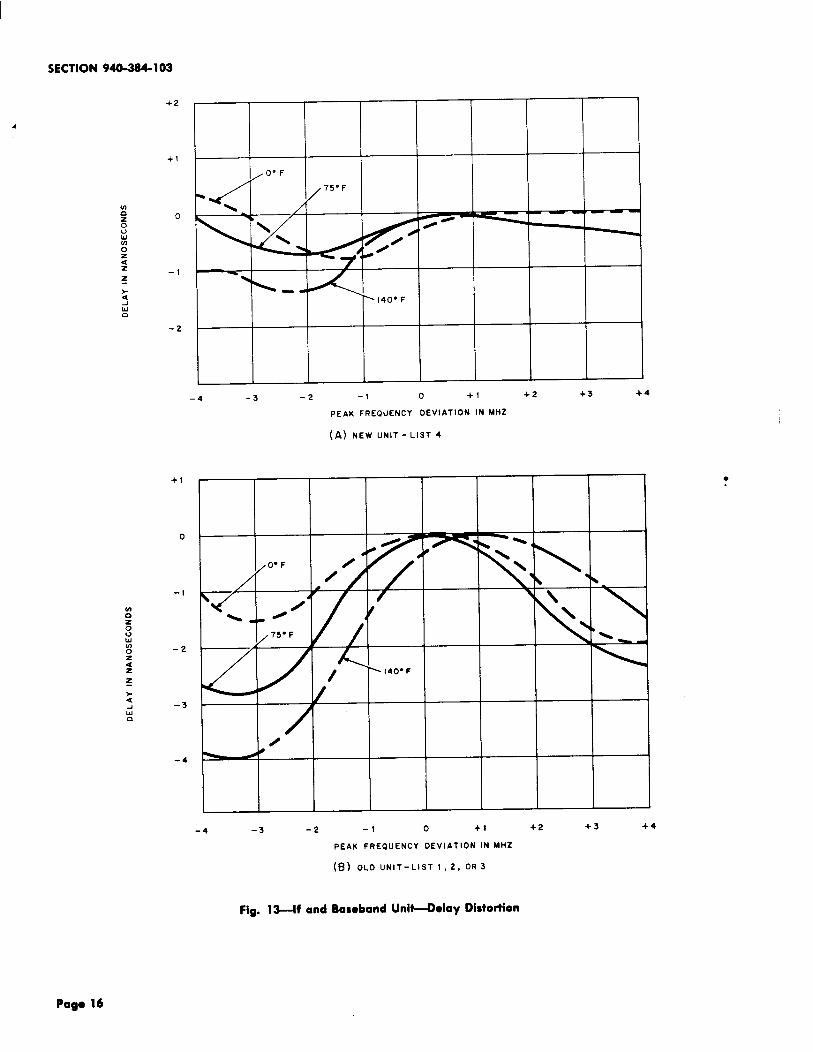
5.12 The envelope delay distortion (EDD) contributedby early units, at room temperature, ranged
as high as 3 to 4 nanoseconds with an 8-MHzpeak-to-peak deviation. The corresponding delayfor the List 4 unit is one nanosecond or less. Thisresults in message-channel noise (pre-emphasized)due to EDD of approximately 12 dBrncO. Figure
13 (A and B) shows the delay contribution of boththe new and the old units to a typical radio hop.
5.13 The output stages of the IF amplifier havebeen modified to provide about 3-dB greater
dynamic range, minimizing a possible overloadcondition. The effects of IF overload appear intwo forms; (1) intermodulationand (2), the limiter operationquite sensitive to dc voltage
noise is increased *and EDD becomeand temperature.
Page 15
SECTION 940-384-103
+2
4
+1
z
0
–!
-2
+1
o
-1
m0zouwIno -2z<zz
-4
-
\. m
‘140” F
-4 -3 -2 -1 0 +1 +2 +3 +4
PEAK FREQUENCY OEVIATION IN MHZ
(A) NEW UNIT- LIST 4
\
/0
-4 -3 -2
Fig. 13--if and
-1 0 +! +2 +3 +4
PEAK FREQUENCY DEVIATION IN MHZ
(B) OLD UNIT-LIST 1,2, 0R3
Baseband Unit-Delay Distortion

1SS 1, SECTION 940-384-103
Improvement of IF output amplifier overloadcapability has minimized the effect of these factorsin limiting system performance at temperatureextremes.
5.14 Improvement of the limiter circuit hassignificantly reduced AM to PM conversion.
In addition, the amount of limiting in the newunit exceeds 40 dB over the entire basebandfrequency range. Limiting in the old unit wasapproximately 20 dB.
5.15 Some radio hops, which had worked wellafter alignment, operated in a degraded
condition when the ambient temperature shiftedappreciably. This reduction of performance wascaused primarily by changes in discriminatorlinearity with temperature. The discriminator andlimiter have been redesigned to achieve a highdegree of linearity over the entire operatingtemperature range<
5.16 In addition to improving the linearity,redesign of the limiter-discriminator has
reduced the idle noise contributed by the IF andbaseband unit about 1 dB at reference drive. Thecorresponding idle-noise contribution of the List 4unit is about 16 dBrncO at room temperature.
5.17 The List 4 unit also contains a manual control● to permit field-setting the squelch level on
an out-of-service basis. This has minimized thenumber of units returned to the factory for minor
t squelch adjustments.
.-5.18 Figure 14 compares the IF selectivity
characteristic of a List 4 unit with that ofa List 1, 2, or 3 unit.
5.19 The overall noise performance of a radio hopwith the new List 4 unit and that of a
typical unit before redesign is summarized in thenoise-loading curves shown in Fig. 15 and 16.These curves compare the 600-circuit noise-loading
performance of the new and the old IF and basebandunits at room temperature and at extremes oftemperature. These curves indicate that thecontribution of the new unit is 6.5 dB below thecurrent overall hop requirement of 25 dBrncO atthe 360-kHz slot and 7 dB below this requirementat 2438 kHz. In contrast, the noise contributionof the old unit under worst temperature conditionsexceeds the overall hop requirement by 4.5 dB at360 kHz and by 0.5 dB at 2438 kHz.
35
30
10
5
n“–
50 60 70 80 90
FREQUENCY IN MHZ
Fig. 14-Selectivit y of IF and Baseband Units
5.20 An IF output is available from the IF andbaseband unit at the IF MON jack for
monitoring purposes or to permit an IF connectionat 70 MHz to other microwave systems. Thepower output at this point is O dBm.
5.21 The final stages of the IF and basebandunit make up the receiver baseband amplifier.
The receiver baseband amplifier is designed toprovide both television and telephone service. Also,the receiver amplifier provides adequate linearityfor the amplifier b contribute negligible intermochdationnoise, differential phase, and differential gain. Thenormal sine wave outDut of the receiver basebandamplifier is + 6.5 dBm for a 4-MHz deviationthe RF signal.
6. ANTENNAS AND WAVEGUIDE SYSTEMS
A. General
of
6.01 Cross-modulation noise caused by waveguideechoes is an important consideration in
engineering short-haul radio systems. Assumingthere are no impairments in the waveguide runs,echo distortion is dependent upon the return lossesof the antenna and radio equipment, waveguideloss, and propagation time in the waveguide. Ifthe equipment return loss is fixed by design andthe waveguide loss and propagation time are a “
Page 17

SECTION 940-384-103
40
35
30
25
20
15
10
r I I I I I IREFERENCE
~ORIVE
II
9
\
/140” F
.-3s -30 -25 -20 -15 -lo
TRANSMITTER ORIVE IN OBM
(A) NEW UNIT-LIST 4 (SLOT AT 360 KHZ)
40
35
30
25
20
Is
10
I
REFERENCEDRIVE
*
4
H
-35 -30 -25 -20 -Is -10
TRANSMITTER ORIVE INOBM
(8) OLO UNIT-LIST 1,2, OR 3 (SLOT AT 360 KHZ)
Fia. 1~Circuit Noise Loadina (Pre-emphasized)
b
.
●
-- “- .
Pago 18

1SS 1, SECTION 940-384-103
*.
●
40
35
30
25
20
Is
10
40
35
30
25
20
15
10
i I
REFERENCE~ ORIVE
I
140” F
\* ~
\ ~
-35
(A)
-30 -25 -20 -15 -lo
TRANSMITTER ORIVE IN DBM
NEW UNIT - LIST 4 ( SLOT AT 2438 KHZ)
II REFERENCE I ] ! II I ‘R’VE4 I I
I 1 I i I I
1 II 1-35 -30 -25 -20 -15 -lo
TRANSMITTER DRIVE IN DBM
(B) OLO UNIT-LIST 1,2, OR 3 (SLOT AT 2438 KHZ)
Fig. 16-600-Circuit Noise Loading (Pre-emphasized)
Page 19
SECTION 940-334-103
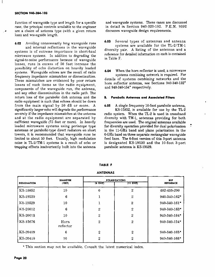
function of waveguide type and length for a specificcase, the principal controls available to the engineer
a are a choice of antenna type (with a given returnloss) and waveguide length.
6.02 Avoiding unnecessarily long waveguide runsand internal reflections in the waveguide
systems is of extreme importance in short-haulmicrowave systems, In addition to degrading thesignal-to-noise performance because of waveguidelosses, runs in excess of 50 feet increase thepossibility of echo distortion on heavily loadedsystems. Waveguide echoes are the result of radiofrequency impedance mismatches or discontinuities.These mismatches are evidenced by poor returnlosses of such items as the radio equipment,components of the waveguide run, the antenna,and any other discontinuities in the radio path. Thereturn loss of the parabolic dish antenna and theradio equipment is such that echoes should be downfrom the main signal by 50 dB or more. Asignificantly larger echo will degrade the performanceseverely if the impedance mismatches at the antennaand at the radio equipment are separated bysufficient waveguide (75 feet or more). In heavilyloaded microwave systems using periscope typeantennas or parabolic-type direct radiators on shorttowers, it is recommended that waveguide runs belimited to about 50 feet. Usually, high modulationnoise in TL2/TM-l systems is a result of echo ortrapping effects inadvertently built into the antenna
and waveguide systems. These cases are discussedin detail in Section 940-320-102. P.E. M. 9392discusses waveguide design requirements.
6.03 Several types of antennas and antennasystems are available for the TL-2/TM-l
diversity pair. A listing of the antennas and a
reference for detailed information on each is containedin Table F.
6.04 When the horn reflector is used, a microwavesystems combining network is required. For
details of systems combining networks and thehorn reflector antenna, see Sections 940-340-132”and 940-340-154” respectively.
B. Parabolic Antennas and Associated Filters
6.05 A single frequency 10-foot parabolic antenna,KS-15852, is available for use by the TL2
radio system. When the TL2 is used in crossbanddiversity with TM-1, antennas providing for bothfrequencies are used. The original antennas available ●
for diversity operation provided for dual polarization “in the 11-GHz band and plane polarization in the6-GHz band on three separate rectangular waveguidefeed lines. The 6-foot version of this 3-port antennais designated KS-19530 and the 10-foot 3-portparabolic antenna is KS-19529.
TABLE F
ANTENNAS
DIAMETER POLARIZATIONS BSP
DESIGNATION (FEET) (6 GHZ) (11 GHZ) REFERENCE
KS-15852 10 0 2 402-435-200
KS-19530 6 1 2 940-340-162”
KS-19529 10 1 2 940-340-161*
KS-20012 6 2 2 940-340-163”
KS-20013 10 2 2 940-340-164*
KS-15676 Horn 2 2 940-340-154”reflector
KS-20409 6 2 2 940-340-165*
KS-2041O 10 2 2 940-340-166”
* This section may not be available. Consult the latest numerical index.
Page 20

1SS 1, SECTION 940-384-103
6.06 In September, 1965, a change was initiatedto minimize intermodulation noise caused by
11-GHz energy coupling into the 6-GHz waveguideat the antenna feed structure. In installations usingKS-19529 and KS-19530 dual-frequency antennas, a1330A filter was added to the 6-GHz wavepuiderun. Typical insertion losses for theproperly terminated, follow:
1330A FILTER
Maximum loss (6-GHz band)Minimum loss (11-GHz band)
6.07 Although the 1330A filter did
1330A, \hen
0.25 dB37.0 dB
its intendedjob, subsequent baseband load tests indicated
a new transmission irregularity had been introduced.An investigation revealed that the 6-GHz waveguiderun between the antenna feed structure and the1330A filter forms a resonant chamber for parasitic11-GHz energy causing irregularities in the 11-GHzchannel transmission path. It was determined thata resistive vane, used in a 6-GHz waveguideattenuator and set for about 0.5-dB loss, insertedimmediately adjacent to the antenna feed structure,is effective in controlling delay distortion arisingin the region of resonances.
6.o8 In May, 1966, a new 1334A filter wasdeveloped for use at locations where it was
impractical to change antenna feed assemblies.: Typical characteristics for the 1334A filter follow:
1334A FILTER
Insertion loss (6-GHz band) 0.6 dBReturn loss (6-GHz band) 30.0 dB
6.09 In January, 1967, a new waveguide filterwas standardized to provide a final solution
to the “long-pipe” reflection and “short-pipe”resonant chamber difficulties encountered whileusing the 3-port crossband parabolic antenna. The1330A and 1334A filters used as an interim solutionwere discontinued for this application. This newtype waveguide filter, KS-20148, which was designedfor absorption at 11 GHz has the followingcharacteristics:
KS.20148 FILTER
Insertion loss (6-GHz band) 0.15 dB
Return loss (6-GHz band) 38.0 dB
6.10 In July, 1967, two dual-frequency 4-portantennas were made available for use by 6-
and 11-GHz systems. These antennas, listed asKS-20012 and KS-20013, permit maximum radioroute growth on short-haul systems equipped forcrossband diversity operation. A KS-20148 filteris required for each 6-GHz port on these antennas.
6.11 In January, 1970, two improved performanceversions of the dual-frequency 4-port antenna
became available. These antennas are listed asKS-20409 and KS-2041O. No external filtering isrequired with these antennas.
C. Waveguide and RF Component Losses
6.12 Table G contains the insertion losses of thevarious components between the transmitter
output and receiver input, together with rectangularwaveguide loss. The TL2 uses WR-90 rectangularwaveguide,
TABLE G
TL-2 WAVEGUIDE AND COMPONENT LOSS
ITEM LOSS (DB)
Transmitter isolator, waveguide 1.30switch, and channel combiningnetwork
Channel dropping network, 1.55RF filter, and receiver isolator
Channel dropping network(through-arm) 0.15
WR-90 waveguide(rigid) o.04/ft(flexible) o.07/ft
6.13 It is suggested that a TL2 component lossof 3.6 dB be applied in path calculations.
This is based on expected worst-channel componentloss for a channel in the third position in a bay.
7. CALCULATION OF RECEIVED CARRIER POWER
7.01 An example of the calculation of receivedcarrier power over a 20-mile hop and utilizing
either a periscope antenna system or a direct *radiator is shown in Table H.
Poge 21

SECTION 940-384-103
TABLE H
CALCULATION OF RECEIVED CARRIER POWER
PERISCOPE DIRECTANTENNA RADIATOR
*Path Loss (20 miles) –143.5 dB –143.5 dB
Waveguide Component Loss – 3.6 dB – 3.6 dB
Waveguide Loss(1) Inside (40 feet ) — 1.6 dB — 1.6 dB(2) Outside (100 feet) — — 4.0 dB
Loss of Two 10-by 15-foot Reflectors – 0.8 dB .
Loss of Two Radomes — 1.8 dB – 1.8 dB
Losses –151.3 dB –154.5 dB
Transmitter Power (minimum) 20.0 dBm 20.0 dBmGain of Two (KS-2041O) 10-Foot Antennas 92.8 dB 92.8 dB
Gains 112.8 dB 112.8 dB
Receiver Carrier Power — 38.5 dBm — 41.7 dBmMaintenance Margin –3dB — 3 dB
Path Design Received Carrier Power — 41.5 dBm — 44.7 dBm
* See Section 940-310-101.
7.o3 A minimum received carrier power of – 45 8. TRANSMISSION PERFORMANCE
dBm (including a 3 dB maintenance margin)at the input to the modulator-preamplifier is A. Noiserequired to meet system design requirements. There~eived signal level, as a-new ‘RF channel isadded to the system may be calculated with thedata provided in Table G. Figure 17 depicts theaddition of channels to a TL2 system.
7.o3 In the example of Fig. 17, assuming theconditions of Table H for a periscopic antenna
system, the received signal level for each channelat the first channel combining network can becalculated using Table G. As additional channelsare added, the received level at this point decreasesby about 0.15 dB from the preceding one.
7.04 At the receiver converter, the signal levelsare reduced by approximately 0.3 dB. Each
added receiver is at the same level as the precedingone, however.
8.01 Noise in the TL2 system based on factorymeasurements of transmitter-receiver units
consists of the following:
FM thermal noise 24.0 dBrncO
Klystron noise 10.0
Modulation noise 20.0
Total noise 25.6
Pre-emphasis advantage 3.5
Expected per-hop noise 22.1 dBrncOperformance
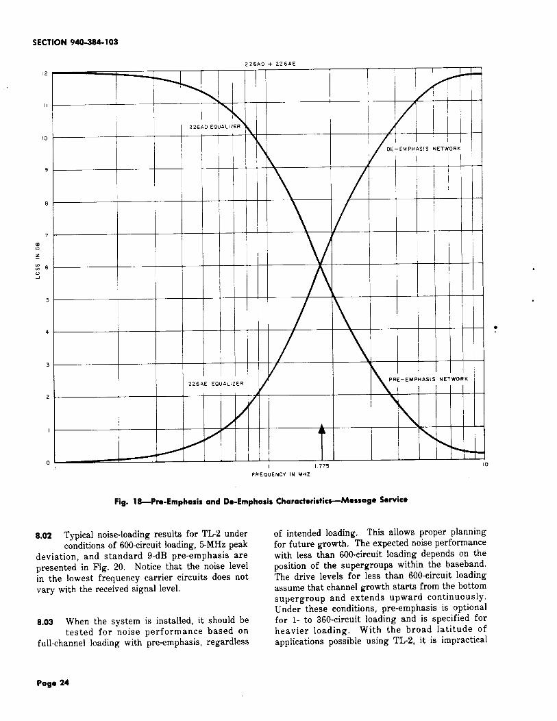
The pre-emphasis characteristic is shown in Fig.18. Message channel noise versus transmitterinput drive for various Lcarrier channel loadingsis plotted in Fig. 19.
●

TO
ANTENNA
1SS 1, SECTION 940-384-103
RCVR I
-;i ‘ERTON -37 9 @
-38 2 @
‘a r ‘T -
-38.5 @
ITRMTR I
CHANNEL CHANNEL
COMBINING DROPPINGBAN DPASSFILTER
ISOLATOR
NETWORK
CONVERTER
NETwORK
J, @/L‘r— ‘r
-t-++ ‘;:V:;EL- - =%‘++:
1TRMTR 2 CHANNEL CHANNEL
COMBINING OROPPINGBAN OPASS
FILTERISOLATOR
NETWORK
CONVERTER
NETWORK
@
T— ?
“ ‘d :’I
TRMTR 3 CHANNEL CHANNEL
COMBINING DROPPINGBANDPASS
● FILTERISOLATOR A CONVERTER
NETWORK NETWORK
wTHIRD CHANNEL
— — — — — — —
[LEVEL AT RCVR
/FOR
(NO OF)
2
3
TRANSMITTERS AND RECEIVERS
uSE OPTION
@
@
o
OPTION OPTION OPTION
@ o @
lRcvR I /-379 ] -3B2 I -3B 51*RCVR 2 -38 5
RCVR 3 -38 5
Fig. 17—Sample Calculations4eceived Signal Level With Growth
Page 23
SECTION 940-384-103
12
II
10
9
8
7
5
4
3
2
I
oI
I
I
I
226AE EQuALIZER
226AD + 226AE
—
<i~ ~
226A0 EQuALIZER
t
/
OE– EMPHASIS NETWORK
AIII
i!
●
Y
PRE-EMPHASIS NETWORK
4
/ \
AA
4
I 775 10
FREQuENCY IN MHZ
Fig. 18-Pre-Emphasis and De-Emphasis Characteristics-Message Service
8.02 Typical noise-loading results for TL2 underconditions of 600-circuit loading, 5-MHz peak
deviation, and standard 9-dB pre-emphasis arepresented in Fig. 20. Notice that the noise levelin the lowest frequency carrier circuits does notvary with the received signal level.
8.03 When the system is installed, it should betested for noise performance based on
full-channel loading with pre-emphasis, regardless
of intended loading. ‘This allows proper planningfor future growth. The expected noise performancewith less than 600-circuit loading depends on theposition of the supergroups within the baseband.The drive levels for less than 600-circuit loadingassume that channel growth starts from the bottomsupergroup and extends upward continuously.Under these conditions, pre-emphasis is optionalfor 1- to 360-circuit loading and is specified forheavier loading. With the broad latitude ofapplications possible using TL-2, it is impractical
Page 24

1SS t, SECTION 940-384-103
42
40
36
36
34
z
w
:30z
28
26
24
●
22
0
.
20
5340 KHZ SLOT1200 CHAN
3 3886 KHZ SLOT
\
REFERENCE2438 KHZ SLOT
DRIvE 600 CHAN
\/
\
\
.
\~
\
-36 -32 -28 -24 – 20 -16 –12
ORIVE IN DBM AT TRANSMITTER INPuT
Fig. 19—Typical Noise Load Curves at – 42 dBm Receiver Modulator Input
to make rigid rules for both the application ofpre-emphasis and adjustment of drive levels. Thefollowing is a suggested method for predictingapproximate noise performance with less than fullloading.
(1) Refer to Fig. 21 to obtain approximateper-hop idle noise versus baseband frequency.
To obtain the idle noise, use the highest modulatingfrequency and the received signal level curvewithout pre-emphasis. Notice that there is afamily of curves dependent on received signallevel. It may be necessary to interpolate to
obtain a value corresponding to a signal levelwhose curve is not shown. Add the results foreach hop in the system on a power (not voltage)basis to obtain the expected total idle noise.
(2) From the results of Step 1, and noting thefrequency location in the baseband of the
supergroups to be used, using Fig. 22 check tosee if pre-emphasis will result in a more uniformsharing of noise between top and bottom circuits.Note that as loading increases, modulation noisewill increase the total noise in the upper frequencycircuits more than in the lower frequency circuits. ,
Page 25

SECTION 940-284-102
30
20
\
\
\
70 KHZ
\
-50 -40 -30 -20RCVR SIGNAL IN OEM
*Fig. 2&Typical Noise Loadin9 performance for 600-Circuit Loading with Pro-Emphasis
(3) For less than 600-circuit loading, the noiseobtained from performing Steps 1 and 2 may
be decreased to reflect the higher per-circuitdrive under these conditions.
CIRCUITS CORRECTION (Dll)
600 0
480 0
360 –0.5
240 –0.5
120 –1.5
The effect of the standard 9-dB pre-emphasischaracteristic on idle noise can be seen in Fig. 18.Its effect on modulation noise is dependent on theproducts involved, but may be assumed to beapproximately the same as for idle noise.
B. Overload
8.04 The TL2 receiver J99296AA List 1 and 2will overload at input signal levels in the
region of – 26 dBm. The J99296AA List 3 will
overload in the – 20 dBm region. If the signallevel is high and other conditions prohibit the useof smaller antennas, attenuation must be placed inthe waveguide system to control the signal level.Under no circumstances should the transmitterrepeller voltage be used to detune the klystron orthe transmitter waveguide switch be partiallyoperated to reduce transmitted power. The resultof overload is high intermodulation noise.
C Linearity and Delay
8.05 The linearity and delay characteristics ofthe receiver are determined by factory
adjustments and are expected to hold for the lifeof the equipment. The linearity of the transmitterklystron is adjustable to optimize overall hoplinearity.
D. Television
8.06 The TL2 radio system is designed to carrya television channel. When planning a TV
route, design for a minimum received carrierpower of –42 dBm.
Page 26

1SS 1, SECTION 940-384-103
25.0
00zKmo
15.0
14 c1
A
/
RCVR INPuT —
/
/ /
{
i / ‘ –35 OBM
RCVR INPUT
)
A /
\/
.0 10 2.0 3.0
BASEBANO FREQuENcY IN MHZ
Pig. 21-idle Noise Per Hop Without Pre-Emphasis
8.07 System alignment is quite different betweentelevision and message service. Optimum
linearizing for message is not optimum for video.For television transmission the transmitter klystronis adjusted to minimize differential gain. Not onlyis the procedure different, but optimum klystrontuning for television transmission is not the sameas the klystron tuning that minimizes cross-modulationin message systems.
8.o8 In addition to the basic RF panel, IF andbaseband equalization is required to meet
TV transmission objectives. There are basically
four types of baseband equalization and two typesof IF equalization. The baseband equalizationconsists of pre-emphasis, low frequency, midband,and high frequency. The IF equalization consistsof linear and parabolic differential phase compensation.These equalizers are mounted on a video panellocated directly below its associated RF panel. Thevideo panel replaces the order wire and alarm orthe diversity switch panel normally provided withmessage systems.
8.09 A new video panel has been designed toreplace the older models of this unit. This ~
new panel provides the equalization and signal
Page 27

SECTION 940-284-102
*
250
[5.0
o 10 20 3.0
BASEBAND FREQuENCY I N MHZ
Fig. 22-idle Noise Per HOP calculated With Pre-Emphasis
level flexibility necessary to meet and maintainbroadcast quality color television transmissionstandards on short-haul radio routes. For detailson both the old and the new video panels, consultSections 409-400-125 and 409-400-126.
8.10 Differential phase is minimized by the useof delay equalizers. These equalizers are
selected from a family of equalizers at the time asystem is installed, based on differential phasemeasurements. The equalizers are inserted betweenthe output of the preamplifier and input to the IFand baseband unit at some repeater locations.
,
.
●
8.11 Differential phase and gain performance canbe improved by the use of pre-emphasis.
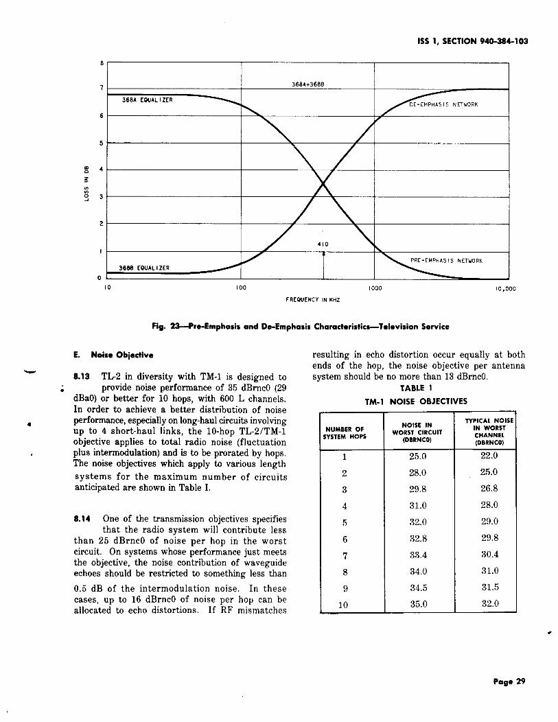
Television systems utilizing TL2 are operated ata peak deviation of 4 MHz with 7 dB of preemphasis.The pre-emphasis characteristic for televisiontransmission is shown in Fig. 23.
8.12 By adjusting the transmitter klystron andby using auxiliary delay equalizers and the
new video panel, it is possible to obtain differential
gain and phase performance of fl.O dB and A1.Odegree for six hops.
Page 28
8
7
6
5
m0 4
z
1SS 1, SECTION 940-384-103
368 A+368B
368A EQUALIZERDE-EMPHASIS NETwORK
x
3
2
I
366S EQUALIZERPRE-EMPHASI S NETwORK
o
10 I 00 I 000
FRCQUENCY IN KHZ
Pig. 23-Pre-Emphasis and De-Emphasis Characteristics-Television Service
E. Noise Obiective
-8.13 TL2 in diversity with TM-1 is designed to
● provide noise performance of 35 dBrncO (29dBaO) or better for 10 hops, with 600 L channels.In order to achieve a better distribution of noise
●performance, especially on long-haul circuits involvingup to 4 short-haul links, the 10-hop TL-2/TM-lobjective applies to total radio noise (fluctuation
4 plus intermodulation) and is to be prorated by hops.The noise objectives which apply to various length
systems for the maximum number of circuitsanticipated are shown in Table I.
8.14 One of the transmission objectives specifiesthat the radio system will contribute less
than 25 dBrncO of noise per hop in the worstcircuit. On systems whose performance just meetsthe objective, the noise contribution of waveguideechoes should be restricted to something less than
0.5 dB of the intermodulation noise. In thesecases, up to 16 dBrncO of noise per hop can beallocated to echo distortions. If RF mismatches
resulting in echo distortion occur
10,000
equally at bothends of-the hop, the noise objective per antennasystem should be no more than 13 dBrncO.
TABLE I
TM-1 NOISE OBJECTIVES
NOISE INTVPICAL NOISE
NUMBER OF WORST CIRCUITIN WORST
YSTEM HOPS (DBRNCO)CHANNEL(DBRNCO)
1 25.0 22.0
2 28.0 25.0
3 29.8 26.8
4 31.0 28.0
5 32.0 29.0
6 32.8 29.8
7 33.4 30.4
8 34.0 31.0
9 34.5 31.5
10 35.0 32.0
Page 29

SECTION 940-384-103
9. DIVERSITY TECHNIQUES
● A. Definitions
9.o1 The following terms are used when discussingdiversity techniques and must be defined.
9.02 Regular and Diversity: These terms arephysical equipment designations and do not
in themselves define operational features. Theyare important in identifying wiring options andspecific equipment arrangements and apply equallyin the case of both bistable and revertive switchapplications. A diversity bay is the radio bay onwhich the diversity switch panel is mounted. Theradio channel assigned to this bay is the diversitychannel. The diversity switch panel is normally notmounted in the regular bay. This bay will mountan order-wire and alarm panel, a video panel, or
no auxiliary panel at all. The radio channel assignedto this bay is the regular channel.
9.o3 Preferred and Nonpreferred: These areoperational terms that have no fixed relation
to equipment arrangements. The preferred channelis the radio channel to which the system will revertat all times except when it is in trouble. Thenonpreferred channel is the radio channel to whichthe system will switch only when the preferredchannel is in trouble. When the trouble is cleared,the system will revert back to the preferredchannel. The preferred channel may be assignedto either the regular or diversity bay dependingupon a wiring option. This option is selected onthe basis of which radio channel of a diversitypair will deliver the better transmission performanceunder normal radio path conditions. The channelengineered with the better performance will receivethe preferred channel assignment.
B. General
9.041 The diversity switch unit automatically ormanually establishes the through baseband
transmission path from the better of two receiversin a diversity pair. The baseband connection ismade through a pair of make-before=break wirespringrelay transfer contacts that provide a noninterruptedor hitless switch under fading conditions. Thetwo signals are in phase as a result of the inverterin the transmitter baseband amplifier. Any levelchanges resulting from the double termination orsignal strength differences are insignificant.
9.o5 Two factors control the switch; the presenceor absence of pilot tone or the variation of
AGC voltage. The switching is controlled by arelay logic circuit which is supplied receiver statusinformation through two receiver pilot monitorsand a fade comparator circuit. The pilot monitorsare selective amplifier detectors which monitor2600-Hz pilot tones at the output of each receiverbaseband amplifier. A 3-dB drop in pilot amplitudefrom an adjustable reference level will initiate theswitching action. The comparator circuit measuresreceiver IF input levels by monitoring the receiverAGC voltages.
9.o6 An optional wire-line connection for activechannel identification and forced-switch feature
is available.
#C. Bistable Switch
9.o7 The bistable switch option is used where *the two channels forming a diversity pair
are nearly equal in performance. The switch doesnot prefer either channel and remains switched to ~one until that channel fades considerably belowthe other (approximately 15 dB) or fails entirely.
D. Revertive Switch
9.08 The revertive switch option is best usedwhere a significant performance difference
(5 or 6 dB) exists between the two channels of adiversity pair. Switch transfer and closure on theprotection channel takes place only during periodsof failure or deep fading on the preferred channeland reverts to the preferred channel when troubleon it clears.
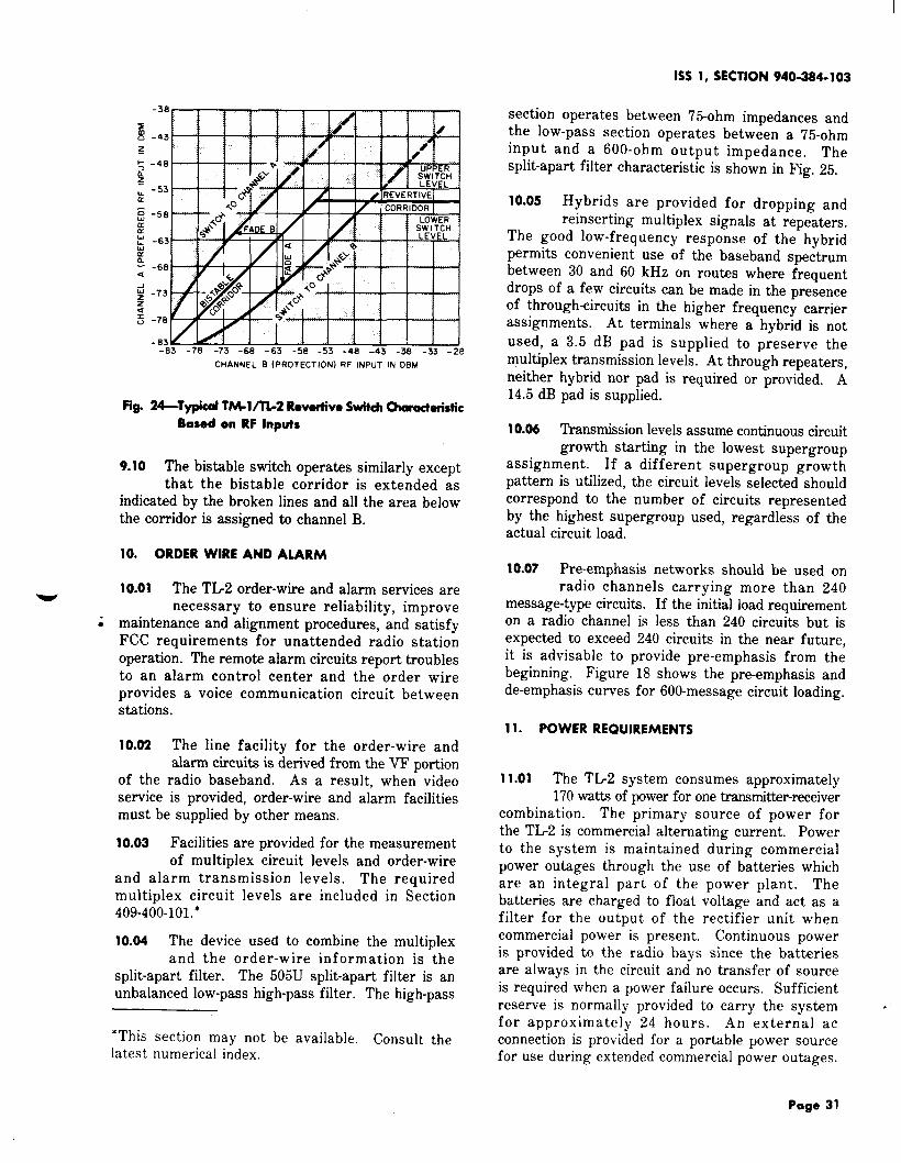
9.o9 The operation of the revertive switch maybe illustrated by means of Fig. 24. If a
point whose coordinates are given by the receivedpower of channel A (preferred) and channel B(protection) falls in the shaded area, the switchwill select channel A. If that point falls in thecrosshatched area, it will switch to channel B. Ifthe point falls in the clear area, the switch willnot operat-it will hold whatever position it has.The width of both corridors shown in Fig. 24 isadjustable.
Page 30
1SS 1, SECTION 940-384-103
CHANNEL B (prOteCtiOn) RF INPUT IN OBM
Fig. 24-Typical TW1/TL2 Revertive Switch Characteristic
Based on RF Inputs
9.10 The bistable switch operates similarly exceptthat the bistable corridor is extended as
indicated by the broken lines and all the area belowthe corridor is assigned to channel B.
10. ORDER WIRE AND ALARM
10.01 The TL2 order-wire and alarm services arew
necessary to ensure reliability, improvei maintenance and alignment procedures, and satisfy
FCC requirements for unattended radio stationoperation. The remote alarm circuits report troublesto an alarm control center and the order wireprovides a voice communication circuit betweenstations.
10.02 The line facility for the order-wire andalarm circuits is derived from the VF portion
of the radio baseband. As a result, when videosewice is provided, order-wire and alarm facilitiesmust be supplied by other means.
10.03 Facilities are provided for the measurementof multiplex circuit levels and order-wire
and alarm transmission levels. The requiredmultiplex circuit levels are included in Section409-4OO-1O1.*
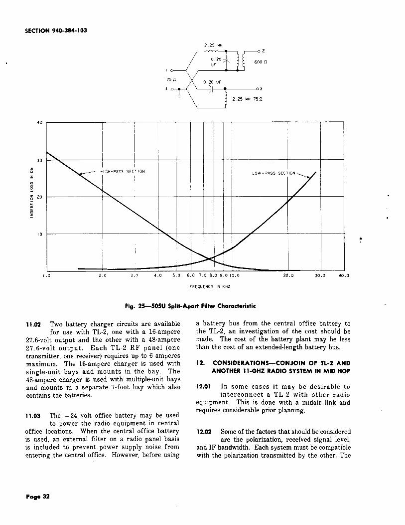
10.04 The device used to combine the multiplexand the order-wire information is the
split-apart filter. The 505U split-apart filter is anunbalanced low-pass high-pass filter. The high-pass
*This section may not be available. Consult thelatest numerical index.
section operates between 75-ohm impedances andthe low-pass section operates between a 75-ohminput and a 600-ohm output impedance. Thesplit-apart filter characteristic is shown in Fig. 25.
10.05 Hybrids are provided for dropping andreinserting multiplex signals at repeaters.
The good low-frequency response of the hybridpermits convenient use of the baseband spectrumbetween 30 and 60 kHz on routes where frequentdrops of a few circuits can be made in the presenceof through-circuits in the higher frequency carrierassignments. At terminals where a hybrid is notused, a 3.5 dB pad is supplied to preserve themultiplex transmission levels. At through repeaters,neither hybrid nor pad is required or provided. A14.5 dB pad is supplied.
10.06 Transmission levels assume continuous circuitgrowth starting in the lowest supergroup
assignment. If a different supergroup growthpattern is utilized, the circuit levels selected shouldcorrespond to the number of circuits representedby the highest supergroup used, regardless of theactual circuit load.
10.07 Pre-emphasis networks should be used onradio channels carrying more than 240
message-type circuits. If the initial load requirementon a radio channel is less than 240 circuits but isexpected to exceed 240 circuits in the near future,it is advisable to provide pre-emphasis from thebeginning. Figure 18 shows the pre-emphasis andde-emphasis curves for 600-message circuit loading.
11. POWER REQUIREMENTS
11.01 The TL2 system consumes approximately170 watts of power for one transmitter-receiver
combination. The primary source of power forthe TL2 is commercial alternating current. Powerto the system is maintained during commercialpower outages through the use of batteries whichare an integral part of the power plant. Thebatteries are charged to float voltage and act as afilter for the output of the rectifier unit whencommercial power is present. Continuous poweris provided to the radio bays since the batteriesare always in the circuit and no transfer of sourceis required when a power failure occurs. Sufficientreserve is normally provided to carry the systemfor approximately 24 hours. An external acconnection is provided for a portable power sourcefor use during extended commercial power outages.
Page 31
SECTION 940-384-103
I I I
2.25 MH
I
75 Q
4
I
%
+1.0 2.0 3.0 4.0
Fig. 25-505U
—
—
—
—
n
—
LOW- PASS SEC TION
#
11.02 Two battery charger circuits are availablefor use with TL-2, one with a 16-ampere
27.6-volt output and the other with a 48-ampere27.6-volt output. Each TL-2 RF panel (onetransmitter, one receiver) requires up to 6 amperesmaximum. The 16-ampere charger is used withsingle-unit bays and mounts in the bay. The48-ampere charger is used with multiple-unit baysand mounts in a separate 7-foot bay which alsocontains the batteries.
11.03 The – 24 volt office battery may be usedto power the radio equipment in central
office locations. When the central office batteryis used, an external filter on a radio panel basisis included to prevent power supply noise fromentering the central office. However, before using
5.0 6.0 7.0 8.0 9.0 10.0 20.0 30.0 40.0
fRCQUENCY IN KHZ
Split-Apart Filter Characteristic
a battery bus from the central office battery tothe TL-2, an investigation of the cost should bemade. The cost of the battery plant may be lessthan the cost of an extended-length battery bus.
12. CONSIDERATIONS—CONJOIN OF 11-2 AND
ANOTHER 11-GHZ RADIO SYSTEM IN MID HOP
12.01 In some cases it may be desirable tointerconnect a TL-2 with other radio
equipment. This is done with a midair link andrequires considerable prior planning.
12.02 Some of the factors that should be consideredare the polarization, received signal level,
and IF bandwidth. Each system must be compatiblewith the polarization transmitted by the other. The
Page 32

●
4
s
received signal level must be held within the rangeof the receiver. This may be accomplished, insome instances, by limiting the power delivered tothe antenna by the other system. The IF bandwidthused by each system must be specified.
12.03 Radio drive level information must beexchanged. Baseband drive level and peak
deviation are both important. The number of messagecircuits or the required system loading may modifythe drive-level information.
12.04 Reemphasis information must be exchanged.The type of pre-emphasis used by each
system must be investigated. System loading maydetermine whether pre-emphasis is necessary, inthis instance.
12.05 It is desirable to noise-load field-test eachsystem with particular emphasis on the
midair link. A check for equalization problems,including special baseband compensation, should bemade. Squelch problems, if any, should beinvestigated.
12.06 There may be a difference in the alarmsystems involved. An agreement must be
reached on which system will alarm the interconnectinglink. Order-wire and pilot transmission levelinformation must be exchanged. It may be necessaryto exchange equipment for the generation of a piloton either end. It is also desirable to interconnectthe order-wire circuits.
13. EQUIPMENT DESIGN
13.01 The TL-2 basic equipment mountingarrangement is either a 7- or a 9-foot 23-inch
bay. A 7-foot bay will accommodate up to sixreceivers or six transmitters, or threereceiver-transmitters. A 9-foot bay is availablefor as many as 4 receiver-transmitter combinations.Power supply, order wire and alarm, diversityswitch, and video panels are also mounted in thesebays. The floor mounting of the TL2 bay is 15inches deep.
13.02 In common with TM-1, TL-2 battery andcharger equipment is mounted in a separate
7-foot 30-inch cabinet. Each battery plant cansupply four receiver-transmitter units of TL2 orTM-1.
1SS 1, SECTION 940-384-103
13.o3 Where growth is limited, equipment for asingle two-way radio channel and battery
plant may both be mounted in a single bay. BothTL2 and TM-1 will utilize the same outdoor cabinet.The cabinet will be 57 inches wide, 77 inches high,and 22 inches deep, The cabinet will house up tofour receivers or four transmitters, or tworeceiver-transmitters. It could accommodate aTL-2 receiver-transmitter plus a TM-1receiver-transmitter.
13.04 The KS-19274 equipment shelter providesboth transportable and mobile type shelters
in a variety of lengths. Available lengths in thetransportable shelter are 7, 12, 16, 20, 24, and 28feet. Equipment arrangements are limited to thefirst 16 feet, thus allowing optimal use of theremaining length. The mobile shelter is 16 feetlong with tandem axle, leaf springs, and fourwheels; a towing eye is provided which will allowconnection to Bell System vehicles equipped withtowing hooks. The mobile shelter is intended forTL2 radio applications of emergency restorationin the 11-GHz frequency band and for use in specialpickup work.
14. PORTABLE EQUIPMENT
14.01 The portable TL-2 units and associatedmobile shelter were developed to provide
a short-haul microwave radio transmitter andreceiver that could be quickly and easily set upat various locations. They are intended primarilyfor emergency restoration of radio, cable, oropen-wire facilities, but should also find applicationwhen providing temporary service or TV pickup.
14.02 Portable TL-2 consists of standard TL-2radio equipment mounted in lightweight,
weathertight, aluminum cases which can be handcarried. The cases are designed for (1) stackingvertically in free-standing groups or for (2) baymounting on special bays in a trailer. The traileris a standard KS- shelter arranged for vehicularuse and described in 13.04.
14.03 The portable arrangement of TL2 providesthe same transmission characteristics as
the standard version for fixed installation. StandardTL-2 plug-in units are used throughout.Frequency-conscious elements are equipped withquick-disconnect clamps for rapid changing of RFchannel assignments in the field. *
Page 33
Ei

SECTION 940-384-103
14.04 The portable packages can be powered fromeither a commercial ac source or a 24-volt
abattery plant. The trailer contains a 390 ampere-hourbattery plant plus charger and has outside connectionsfor obtaining 115-volt ac from either a power lineor a mobile generator.
409-400-102 TL-2 Transmitter-ReceiverCabinet and Bay
409-400-103 TL2 Transmitter
409-400-104 TL2 Receiver
15. REFERENCES
BELL SYSTEM TECHNICAL JOURNAL—TheTM-1/TL2 Short Haul Microwave Systems—Jan.1966
AA388.171 Short-Haul Radio Systems
AA388.158 TL-2 Radio—Transmitter-Receiver Equipment
409-400-125,126 Video Panels
409-403-503 System Tests—TelevisionTransmission
409-403-505 System Tests—600 Circuit—Noise-Loading
Page 34
34 Pages