radiation generators - american association of … · radiation generators physics review course...
TRANSCRIPT

RADIATION GENERATORS
Physics Review Course 52nd Annual Meeting, AAPM
Philadelphia, PA July 17th, 2010
Peter J. Biggs Ph.D., Associate Professor and Radiation Biophysicist
Department of Radiation Oncology, Massachusetts General Hospital,
Harvard Medical School, Boston, MA 02114

Therapy Physics Review Course: Radiation Generators July 17th, 2010
Page 2
Radiation Generators A. Kilovoltage units 1. Contact units 2. Superficial units 3. Orthovoltage units B. Teletherapy units 1. Source & housing 2. Collimator, penumbra 3. Radiation characteristics C. Linear accelerators 1. Principles of linear accelerators 2. Cavity operation 3. RF power sources 4. Electron gun 5. Accelerator layout 6. Accelerator waveguide 7. Beam loading 8. Main power supply 9. Low vs. medium/high energy linear accelerators 10. Magnet systems 11. Target and flattening filter 12. Photon/electron beam delivery systems (incl. beam monitoring and collimator assembly) 13. Electron linear accelerators with dual-energy photon beams 14. Neutron background. 15. Other physical characteristics of linear accelerators 16. Features of computer controlled linear accelerators D. Properties of megavoltage beams
1. Percent depth dose curves 2. Penumbra
Therapy Physics Review Course: Radiation Generators July 17th, 2010
Page 3
A Kilovoltage units - Conventional definition is that : (1) contact therapy refers to equipment operating with X-rays
tubes at an accelerating potential < 50 kV, (2) superficial therapy refers to potentials of 50-150 kV and (3) orthovoltage unit refers to potentials of 150-500 kV. Other authors have defined these ranges in many different ways, but these ranges generally agree with, or at least overlap, other definitions.
- Maximum dose is at the surface, so clinical use is of these units is often restricted to superficial
lesions and, sometimes, intraoperative radiation therapy. Note that currently, there are only two manufacturers of kilovoltage x-ray units. These units offer ranges of beam quality that cover two or three of the classes of therapy (see below).
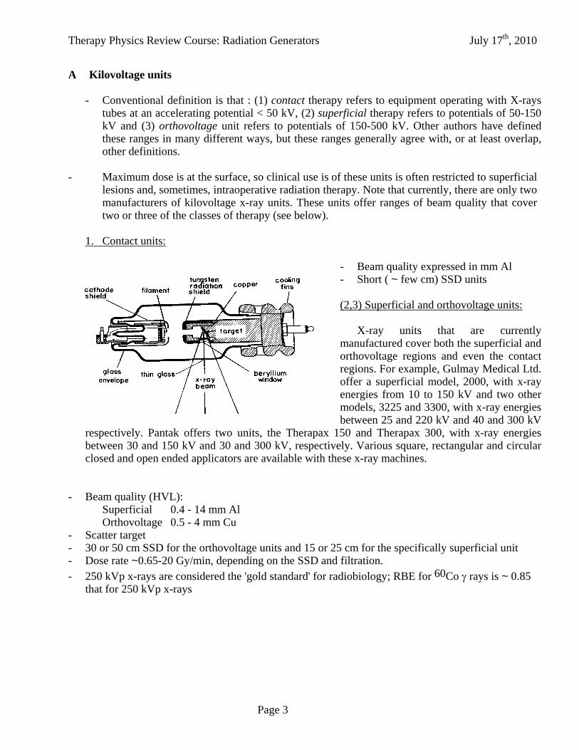
1. Contact units:
- Beam quality expressed in mm Al -- Short ( ~ few cm) SSD units - (2,3) Superficial and orthovoltage units: X-ray units that are currently manufactured cover both the superficial and orthovoltage regions and even the contact regions. For example, Gulmay Medical Ltd. offer a superficial model, 2000, with x-ray energies from 10 to 150 kV and two other models, 3225 and 3300, with x-ray energies between 25 and 220 kV and 40 and 300 kV
respectively. Pantak offers two units, the Therapax 150 and Therapax 300, with x-ray energies between 30 and 150 kV and 30 and 300 kV, respectively. Various square, rectangular and circular closed and open ended applicators are available with these x-ray machines.
- Beam quality (HVL): Superficial 0.4 - 14 mm Al Orthovoltage 0.5 - 4 mm Cu
- Scatter target - 30 or 50 cm SSD for the orthovoltage units and 15 or 25 cm for the specifically superficial unit - Dose rate ~0.65-20 Gy/min, depending on the SSD and filtration. - 250 kVp x-rays are considered the 'gold standard' for radiobiology; RBE for 60Co rays is ~ 0.85
that for 250 kVp x-rays
Therapy Physics Review Course: Radiation Generators July 17th, 2010
Page 4
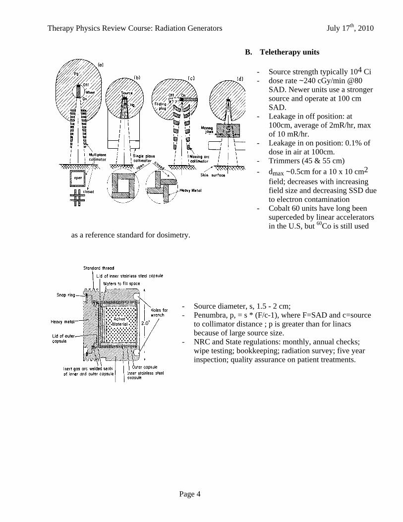
B. Teletherapy units - Source strength typically 104 Ci - dose rate ~240 cGy/min @80
SAD. Newer units use a stronger source and operate at 100 cm SAD.
- Leakage in off position: at 100cm, average of 2mR/hr, max of 10 mR/hr.
- Leakage in on position: 0.1% of dose in air at 100cm.
- Trimmers (45 & 55 cm) - dmax ~0.5cm for a 10 x 10 cm2
field; decreases with increasing field size and decreasing SSD due to electron contamination
- Cobalt 60 units have long been superceded by linear accelerators in the U.S, but 60Co is still used
as a reference standard for dosimetry.
- Source diameter, s, 1.5 - 2 cm; - Penumbra, p, = s * (F/c-1), where F=SAD and c=source
to collimator distance ; p is greater than for linacs because of large source size.
- NRC and State regulations: monthly, annual checks; wipe testing; bookkeeping; radiation survey; five year inspection; quality assurance on patient treatments.

Therapy Physics Review Course: Radiation Generators July 17th, 2010
Page 5
C. Linear accelerators 1. Acceleration principle: a. WHAT KIND OF POWER SOURCE IS NEEDED FOR LINEAR ACCELERATORS ?
1. Why not DC?
- Problems of electrical breakdown, physical size of electrical equipment 2. Apply technique of repeated pulses, viz.
V = nv - Need oscillating form of power supply
3. Leads to principle of cyclic and linear accelerators 4. Wavelength has to be short enough to accelerate electrons in a reasonable distance 5. S-band microwave technology, developed for radar in WWII, has a frequency of ~ 3 GHz or
= 10 cm. 6. High power is also needed to ensure sufficient energy gain per cycle
At high energies (> 0.5 MV), it is impractical to use DC voltages to accelerate the electrons and,
instead, the principal of repeated application of a constant voltage is used, so that an oscillating form of power supply is needed. Both linear accelerators and cyclic accelerators are based on this principle.
The wavelength has to be short enough to make the accelerators reasonably small. S band microwave technology, developed for radar in WWII, has a frequency of ~3 GHz or =10 cm and has been extensively developed for radiation therapy. It is interesting to note, however, that an x-band waveguide (x3 frequency) has recently been developed for medical applications, namely a portable electron-only linear accelerator (< 12 MeV), where a short waveguide is essential.
Therapy Physics Review Course: Radiation Generators July 17th, 2010
Page 6
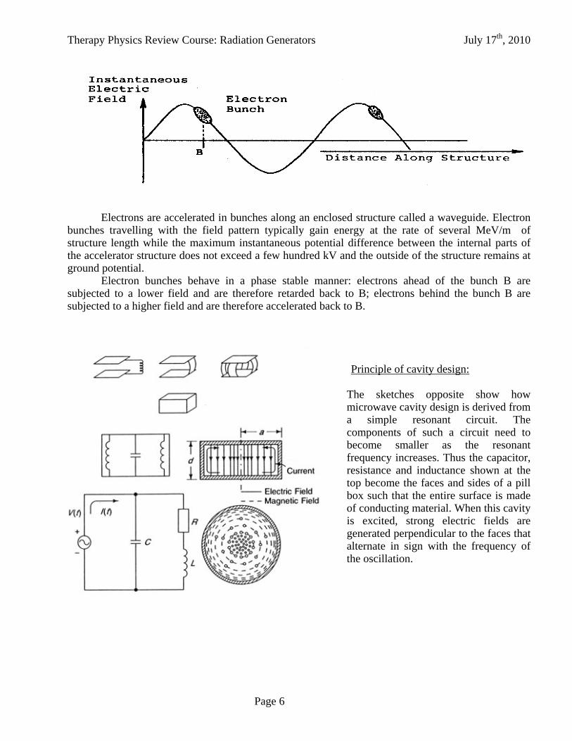
Electrons are accelerated in bunches along an enclosed structure called a waveguide. Electron
bunches travelling with the field pattern typically gain energy at the rate of several MeV/m of structure length while the maximum instantaneous potential difference between the internal parts of the accelerator structure does not exceed a few hundred kV and the outside of the structure remains at ground potential.
Electron bunches behave in a phase stable manner: electrons ahead of the bunch B are subjected to a lower field and are therefore retarded back to B; electrons behind the bunch B are subjected to a higher field and are therefore accelerated back to B.
Principle of cavity design:
The sketches opposite show how microwave cavity design is derived from a simple resonant circuit. The components of such a circuit need to become smaller as the resonant frequency increases. Thus the capacitor, resistance and inductance shown at the top become the faces and sides of a pill box such that the entire surface is made of conducting material. When this cavity is excited, strong electric fields are generated perpendicular to the faces that alternate in sign with the frequency of the oscillation.

Therapy Physics Review Course: Radiation Generators July 17th, 2010
Page 7
Therapy Physics Review Course: Radiation Generators July 17th, 2010
Page 8
3. Cavity operation: a. GENERATION OF HIGH POWER MICROWAVE PULSES
1. At high frequencies, ordinary resonant circuits become impractical. Also problems of radiation loss
2. Hollow cavities as resonant circuits (skin effect) 3. The quality factor, or Q value, of a resonant circuit or cavity is defined as
Q = energy stored in cycle
energy lost/cycle
For a circuit, Q ~ 102, whereas for a cavity, Q ~ 10 4. Achieved through devices called magnetrons and klystrons 5. To understand these devices, need to consider properties of cavity resonators 6. Cavity resonators feature in both power sources and accelerating structures
b. ROLE OF RESONANT CAVITIES IN LINEAR ACCELERATORS
1. Cavity acts as an acceleration module 2. Multiple cavity arrangement can act as an RF amplifier - klystron 3. Multiple cavity arrangement can act as a high power oscillator - magnetron

Therapy Physics Review Course: Radiation Generators July 17th, 2010
Page 9
- The standard technique of resonant circuits using discrete capacitative, resistive and inductive components no longer suffices at a frequency of 3 GHz, because of the extremely small dimensions required and the high energy losses of such systems.
- in general, =(LC)-1/2 for a resonant circuit, so one needs very small L and C and hence small dimensions to obtain high frequencies, so ordinary resonant circuits become impractical. This leads to the use of cavities as a form of resonant circuit since they have low L and C.
- electric, magnetic field configurations for lowest resonant mode are shown in the diagrams. Note that only the electric field plays a role in electron acceleration.
- electric field configuration in cylindrical microwave cavity with hole on axis for electrons to pass through is only slightly modified
- Efficient transfer of energy to electron beam, i.e., low energy losses, since for a resonant circuit, Q ~ 102 (where Q=f0/2f and 2f is FWHM), whereas for a cavity, Q ~ 104

Therapy Physics Review Course: Radiation Generators July 17th, 2010
Page 10
3. RF Power sources:
Generation of high power microwave pulses is achieved through devices called magnetrons and klystrons. Both devices embody the principles of cavity resonators. a. Klystron
- acts as a power amplifier - suitable for high energy
accelerators (> 10 MV) - practical units generally
have several stages - typically 20 MW peak
power and 20 kW average power
b. Magnetron
The principle of the
magnetron is illustrated in figure 47. A cylindrical anode has the cathode along its axis. A magnetic field is directed along the axis of the cylinder. At low magnetic fields, the electron paths’ are bent, but the electrons still reach the anode. At a field Bc, the electron paths’ just graze the anode. For higher fields, individual electrons are unable to reach the anode. Figure 48 shows, above, a simplified experimental arrangement and, below, the variation in anode current with magnetic

Therapy Physics Review Course: Radiation Generators July 17th, 2010
Page 11
field.
Under static conditions, no electrons would reach the anode and there would be a cylindrical space charge of diameter less than the inner diameter of the anode. This space charge would, in effect, circulate around the cathode with an angular velocity depending on the anode potential and the magnetic flux density. However, the circulating electrons induce a charge distribution between adjacent segments of the anode in a manner similar to that in the catcher cavity of the klystron and an electric field of microwave frequency. This, in turn, perturbs the electron orbits so that the space charge distribution into a form resembling the spokes of a wheel. The electrons interact with the electric fields generated in these gaps and, under certain conditions, the resonant cavities gain energy from the orbiting electrons which are slowed and eventually spiral into the anode, leading to anode current.
- cross section through 12 cavity magnetron - magnetic field is applied perpendicular to the
paper, along the axis of the cavity - acts as a high power oscillator - suitable for low energy accelerators (4, 6 MV) - more unstable than klystron - typically 2-3 MW peak power - average lifetime ~ 1 yr (can be extended by running at a lower dose
rate)

Therapy Physics Review Course: Radiation Generators July 17th, 2010
Page 12
- Schematic of electron source (gun) and prebuncher cavity
5. Accelerator layout:
Schematic of accelerator components, including:
- electron gun - prebuncher cavity - buncher cavity - accelerating guide Note that in the injector section, the velocity of the electron varies as its energy increases while in the accelerator section it is essentially constant.
4. Electron gun:
Therapy Physics Review Course: Radiation Generators July 17th, 2010
Page 13
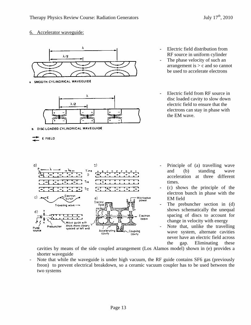
6. Accelerator waveguide: - Electric field distribution from
RF source in uniform cylinder - The phase velocity of such an
arrangement is > c and so cannot be used to accelerate electrons
- Electric field from RF source in
disc loaded cavity to slow down electric field to ensure that the electrons can stay in phase with the EM wave.
- Principle of (a) travelling wave
and (b) standing wave acceleration at three different times.
- (c) shows the principle of the electron bunch in phase with the EM field
- The prebuncher section in (d) shows schematically the unequal spacing of discs to account for change in velocity with energy
- Note that, unlike the travelling wave system, alternate cavities never have an electric field across the gap. Eliminating these
cavities by means of the side coupled arrangement (Los Alamos model) shown in (e) provides a shorter waveguide
- Note that while the waveguide is under high vacuum, the RF guide contains SF6 gas (previously freon) to prevent electrical breakdown, so a ceramic vacuum coupler has to be used between the two systems

Therapy Physics Review Course: Radiation Generators July 17th, 2010
Page 14
7. Beam Loading
Since the electron beam in the waveguide gains energy from the RF field, it follows that for a fixed microwave power level, the more energy the electron beam gains, the lower the current. Conversely, at low energies, the current can be much higher since less power is required to accelerate the electrons. This is known as the load line (dashed line in figure) for the waveguide. Its exact shape depends on the guide design and the power applied. However, since x-ray production increases with energy, the x-ray output from the machine displays the form shown by the solid line in the figure with a maximum output at a particular
energy. This is the normal operating energy for x-rays. If a different energy is selected, the output will be lower (see section 11).
8. Main power supply and modulator
The main power supply is a
conventional high-voltage, high-current power supply which charges the pulse forming network (PFN) of the modulator during each inter-pulse period. The PFN is discharged through the primary winding of a pulse transformer by a high power thyratron and delivers high-voltage, high-current pulses to the klystron or magnetron (and sometimes to the electron gun) connected to the winding(s) of the pulse transformer. The length of the high voltage pulse is fixed by the parameters of the PFN. However, the length of the RF pulse produced by a high power klystron can be changed by altering the length of the RF drive pulse.
Similar control of the magnetron oscillator RF pulse length is obviously not possible.

Therapy Physics Review Course: Radiation Generators July 17th, 2010
Page 15
9. Low vs. medium/high energy linear accelerators:
The upper
diagram shows the short waveguide of a low energy linear accelerator pointing directly towards the target. It is possible to accommodate the guide in this direction and still maintain a floor to isocenter height that is acceptable to therapists. For a medium/high energy linear accelerator, however, this is not possible and the waveguide is aligned parallel to the gantry rotation axis. A 270° magnet bends the beam onto the target. The low energy machine does not require this magnet and therefore has a
larger energy spread than the machine with the magnet (typically ±3% using slits).

Therapy Physics Review Course: Radiation Generators July 17th, 2010
Page 16
10. Magnet systems:
- Principle of 270° bending
magnet (Enge). Note the achromatic focus vs. a dispersed focus for the 90° magnet.
- alternative, more complicated bending techniques, using quadrupoles and/or additional bending magnets, to achieve an achromatic focus

Therapy Physics Review Course: Radiation Generators July 17th, 2010
Page 17
11. Target and flattening filter:
- a flattening filter is used to obtain a broad beam for clinical use. High Z materials are usually used at low energies and intermediate Z values at high energies.
- Comparison between the energy spectra for linear accelerators (‘thick’ target) and betatrons (‘thin’ target). Not the higher proportion of high energy photons for the betatron spectrum.
- The mass attenuation coefficient
graph shows that the minimum value for lead is around 2 MV (the rise at higher energies is due to pair production). Thus, for high energy beams (>10 MV), a flattening filter made of this material will soften the beam. For lower Z materials, such as iron, this minimum is

Therapy Physics Review Course: Radiation Generators July 17th, 2010
Page 18
higher and there is no beam softening at high energies. 12. Photon/electron beam delivery systems:
- schematic representation of a clinical x-ray beam showing the target, primary collimator, flattening filter, ion chamber and secondary collimators.

Therapy Physics Review Course: Radiation Generators July 17th, 2010
Page 19
- schematic representation of a clinical electron beam showing the x-ray target and flattening filter withdrawn, the scattering foils in place and the electron applicator to provide a sharp penumbra. Note that because flattening filters are not used in electron beam production, the amount of internal electron beam current is 20-100 x lower than for photon beams.
Therapy Physics Review Course: Radiation Generators July 17th, 2010
Page 20
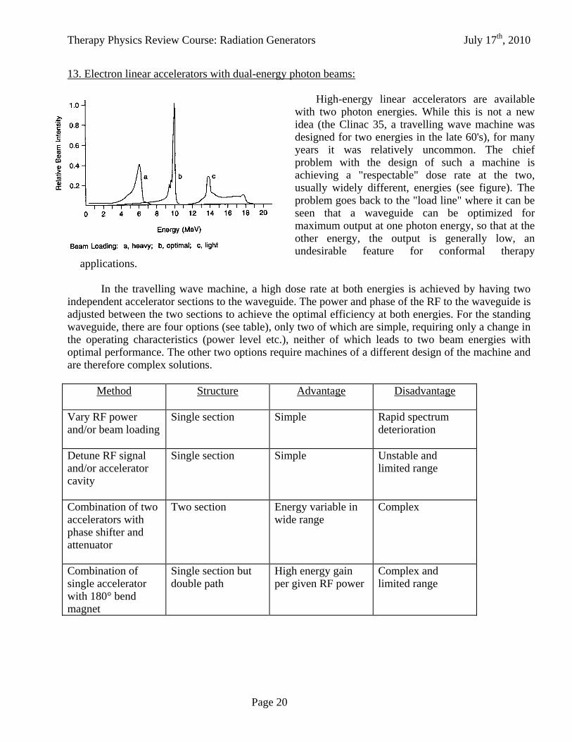
13. Electron linear accelerators with dual-energy photon beams:
High-energy linear accelerators are available with two photon energies. While this is not a new idea (the Clinac 35, a travelling wave machine was designed for two energies in the late 60's), for many years it was relatively uncommon. The chief problem with the design of such a machine is achieving a "respectable" dose rate at the two, usually widely different, energies (see figure). The problem goes back to the "load line" where it can be seen that a waveguide can be optimized for maximum output at one photon energy, so that at the other energy, the output is generally low, an undesirable feature for conformal therapy
applications.
In the travelling wave machine, a high dose rate at both energies is achieved by having two independent accelerator sections to the waveguide. The power and phase of the RF to the waveguide is adjusted between the two sections to achieve the optimal efficiency at both energies. For the standing waveguide, there are four options (see table), only two of which are simple, requiring only a change in the operating characteristics (power level etc.), neither of which leads to two beam energies with optimal performance. The other two options require machines of a different design of the machine and are therefore complex solutions.
Method
Structure Advantage Disadvantage
Vary RF power and/or beam loading
Single section Simple Rapid spectrum deterioration
Detune RF signal and/or accelerator cavity
Single section Simple Unstable and limited range
Combination of two accelerators with phase shifter and attenuator
Two section Energy variable in wide range
Complex
Combination of single accelerator with 180° bend magnet
Single section but double path
High energy gain per given RF power
Complex and limited range

Therapy Physics Review Course: Radiation Generators July 17th, 2010
Page 21
Therapy Physics Review Course: Radiation Generators July 17th, 2010
Page 22
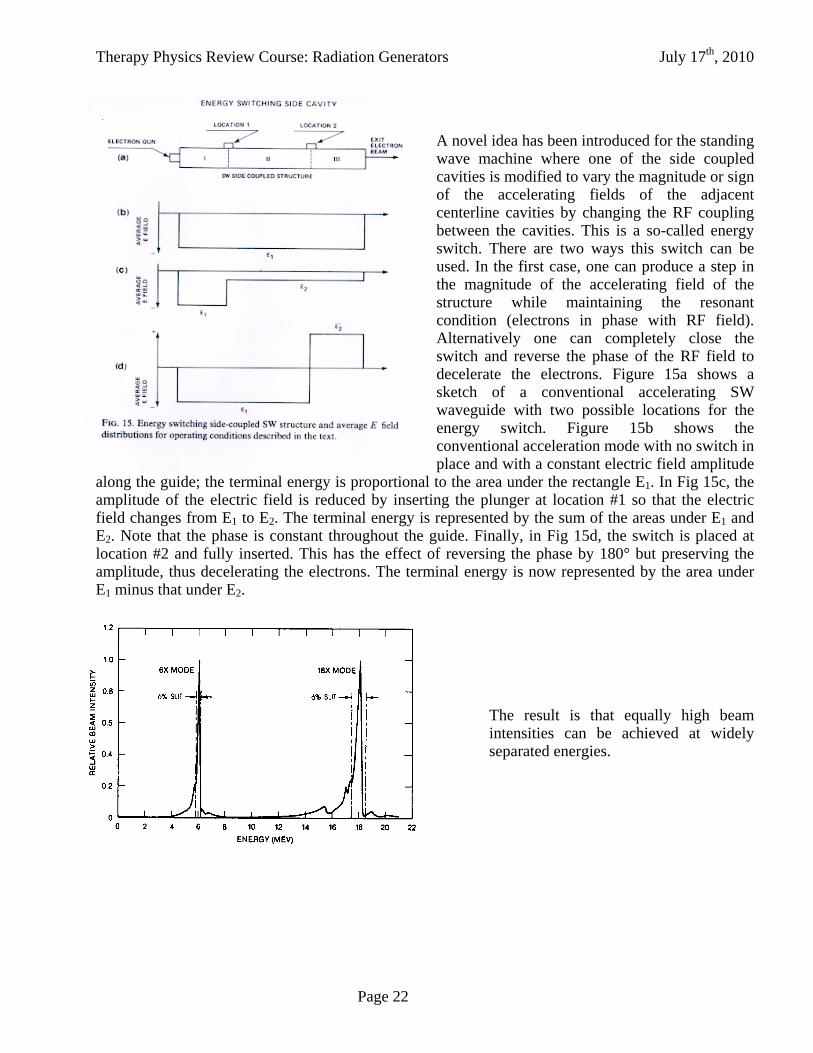
A novel idea has been introduced for the standing wave machine where one of the side coupled cavities is modified to vary the magnitude or sign of the accelerating fields of the adjacent centerline cavities by changing the RF coupling between the cavities. This is a so-called energy switch. There are two ways this switch can be used. In the first case, one can produce a step in the magnitude of the accelerating field of the structure while maintaining the resonant condition (electrons in phase with RF field). Alternatively one can completely close the switch and reverse the phase of the RF field to decelerate the electrons. Figure 15a shows a sketch of a conventional accelerating SW waveguide with two possible locations for the energy switch. Figure 15b shows the conventional acceleration mode with no switch in place and with a constant electric field amplitude
along the guide; the terminal energy is proportional to the area under the rectangle E1. In Fig 15c, the amplitude of the electric field is reduced by inserting the plunger at location #1 so that the electric field changes from E1 to E2. The terminal energy is represented by the sum of the areas under E1 and E2. Note that the phase is constant throughout the guide. Finally, in Fig 15d, the switch is placed at location #2 and fully inserted. This has the effect of reversing the phase by 180° but preserving the amplitude, thus decelerating the electrons. The terminal energy is now represented by the area under E1 minus that under E2.
The result is that equally high beam intensities can be achieved at widely separated energies.
Therapy Physics Review Course: Radiation Generators July 17th, 2010
Page 23
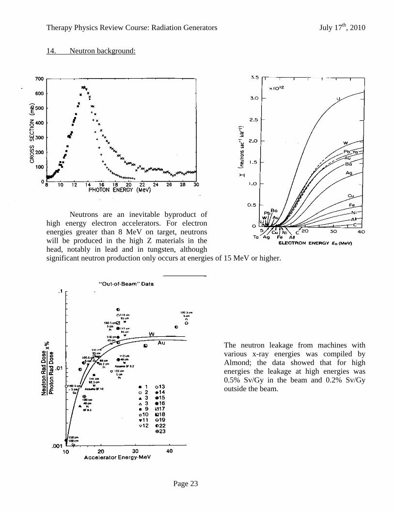
14. Neutron background:
Neutrons are an inevitable byproduct of high energy electron accelerators. For electron energies greater than 8 MeV on target, neutrons will be produced in the high Z materials in the head, notably in lead and in tungsten, although significant neutron production only occurs at energies of 15 MeV or higher.
The neutron leakage from machines with
various x-ray energies was compiled by Almond; the data showed that for high energies the leakage at high energies was 0.5% Sv/Gy in the beam and 0.2% Sv/Gy outside the beam.
Therapy Physics Review Course: Radiation Generators July 17th, 2010
Page 24
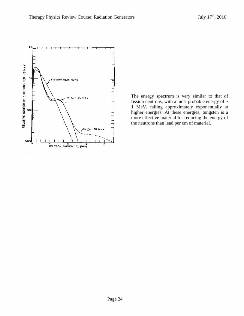
The energy spectrum is very similar to that of fission neutrons, with a most probable energy of ~ 1 MeV, falling approximately exponentially at higher energies. At these energies, tungsten is a more effective material for reducing the energy of the neutrons than lead per cm of material.

Therapy Physics Review Course: Radiation Generators July 17th, 2010
Page 25
Neutrons with energies below 2 MeV are very
poorly attenuated by lead, but less so by iron and tungsten. Curves of the half energy thickness, or the thickness to reduce the energy by one half, increase very rapidly as the neutron energy goes below 1 MeV. Unfortunately, these are the typical neutron energies from high energy linear accelerators.

Therapy Physics Review Course: Radiation Generators July 17th, 2010
Page 26
15. Other physical characteristics of linear accelerators:
- Compromise between flatness for small and large fields with single flattening filter - Photon characteristics: dmax vs. energy,
~ 3mm beam spot; smaller penumbra vs. 60Co - Electron beams: Profile shaping applicators, scanning beams; scanning beams have lower
bremsstrahlung background at high energies - Dose rates: 4 & 6 MV machines - 250 cGy/min, now up to 600 cGy/min High energy, dual energy machines - 100-600 cGy/min - Neutrons: Threshold at ~10 MV, plateau at ~20-25 MV - Dual Dose monitoring system plus check cycle for safety
16. Features of computer controlled linear accelerators:
- multileaf collimators Leaf resolution is generally 1 cm at isocenter, but now units are available with 0.5 cm resolution for small fields. Micro-MLCs have a resolution of 4 mm.
- dynamic wedges - beam intensity modulation - better handling of beam diagnostics, locally and remotely

Therapy Physics Review Course: Radiation Generators July 17th, 2010
Page 27
Variation of Percent Depth Dose at Field Size for 18 MV Photons
0
10
20
30
40
50
60
70
80
90
100
0 5 10 15 20 25 30 35 40 45
Depth in Water (cm)
Per
cen
t D
epth
Dos
e
4x410x10
40x40
Variation of Percent Depth Dose at Field Size for 4 MV Photons
0
10
20
30
40
50
60
70
80
90
100
0 5 10 15 20 25 30 35 40
Depth in Water (cm)
Per
cen
t D
epth
Dos
e
30x30
10x105x5
Variation of Percent Depth Dose with Energy
0
10
20
30
40
50
60
70
80
90
100
0 5 10 15 20 25 30 35 40 45
Depth in Water (cm)
Per
cen
t D
epth
Dos
e
18 MV
10 MV6 MV
4 MV
D. Properties of megavoltage x-ray beams 1. Percent depth dose curves
As seen earlier, the x-ray spectrum from linear accelerators is a bremstrahlung spectrum. That means that there are relatively few photons near the peak energy compared with at lower energies. A rule of thumb, developed in the early days of linear accelerators was that the average energy was 1/3 of the peak energy, but this is only approximately true at high energies. Monte Carlo studies of primary bremsstrahlung spectra indicate average photon energies of 1.76, 2.55 and 4.75 for 6, 10 and 25 MV x-ray beams respectively. Unlike orthovoltage x-rays, the maximum dose occurs at depth, not at the surface. This depth of maximum dose depends on both the maximum photon energy and the field size of the beam.
a. Energy dependence: The depth of maximum dose increases with energy, but not linearly. This non-linearity is probably related to contribution from electrons generated in the head skewing the depth dose curve. Depth dose curves for 4, 6, 10 and 18 MV are shown in the curve above. At 4 MV, the depth is about 1 cm, whereas for 18 MV it is closer to 3.5 cm.
b. Field size dependence: The depth of maximum dose decreases with field size due to contamination from electrons generated in the head. This is more severe for the high energy than for low energy beams. This is illustrated in the curves shown below for 4 MV and 18 MV.

Therapy Physics Review Course: Radiation Generators July 17th, 2010
Page 28
Variation of Maximum Depth Dose with Energy
0
0.5
1
1.5
2
2.5
3
3.5
4
0 2 4 6 8 10 12 14 16 18 20
Beam Energy (MV)
Dep
th o
f M
axi
mu
m D
ose
(cm
)
4 MV
6 MV
10 MV
18 MV
Variation of Depth of Maximum Dose wth Field Size
0
0.5
1
1.5
2
2.5
3
3.5
4
4.5
0 5 10 15 20 25 30 35 40 45
Size of Square Field (cm)
Dep
th o
f M
axi
mu
m D
ose
(cm
)
18 MV
4 MV
c. Depth of maximum dose: The variation of the depth of
maximum dose, dmax, with energy is shown for 4, 6, 10 and 18 MV, illustrating the range in dmax and its non-linearity with energy. The error bars indicate 2 mm uncertainty on the measurements.
This plot shows more clearly that there is a greater variation of dmax with field size at high energies than at low energies. At 18 MV, for example, dmax varies from about 3.5 cm at small field sizes to almost 2.5 for large field sizes. In contrast, the variation at 4 MV is barely perceptible and amounts to no more than 1 mm.
d. Surface dose: The surface dose varies with energy, field size and accessory placement, such as a wedge of blocking tray. In general, the surface dose increases with all these parameters due to electron contamination. The surface dose also increases with decreasing SSD for the same reason.
Therapy Physics Review Course: Radiation Generators July 17th, 2010
Page 29
Beam Profiles for a 40x40 Field at 18 MV
0
20
40
60
80
100
-40 -30 -20 -10 0 10 20 30 40
Distance (cm)
Rel
ati
ve D
ose
29.99 cm
20.00 cm
10.00 cm
5.03 cm
2.53 cm
Variation of Penumbra with Depth for 6, 10 and 18 MV X-Rays
0.50
0.70
0.90
1.10
1.30
1.50
1.70
0.00 5.00 10.00 15.00 20.00 25.00 30.00
Depth in water (cm)
Pen
um
bra
(80
% -
20%
) (c
m)
6MV rt (30x30)6MV lft (30x30)10MV rt (30x30)10MV lft (30x30)18V 6x618MV 20x20
6 MV
10 MV
18 MV
However, different machines having the same energy may have a different surface dose due to different head design.
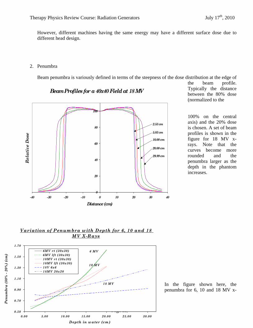
2. Penumbra
Beam penumbra is variously defined in terms of the steepness of the dose distribution at the edge of the beam profile. Typically the distance between the 80% dose (normalized to the 100% on the central axis) and the 20% dose is chosen. A set of beam profiles is shown in the figure for 18 MV x-rays. Note that the curves become more rounded and the penumbra larger as the depth in the phantom increases.
In the figure shown here, the penumbra for 6, 10 and 18 MV x-

Therapy Physics Review Course: Radiation Generators July 17th, 2010
Page 30
rays is shown as a function of depth in water. It can be seen that the penumbra increases with depth, as might be expected form the increase in photons scattered out of the beam. It also decreases with increasing energy and field size.
Therapy Physics Review Course: Radiation Generators July 17th, 2010
Page 31
References
Ford J.C. Advances in accelerator design. AAPM, Medical Physics Monograph #15. Johns H.E. and Cunningham J.R. The physics of radiology. C.C.Thomas, Springfield, Illinois. Fourth
edition, 1983. Karzmark C.J. Advances in linear accelerator design for radiotherapy. Med. Phys. 11;105-128, 1984. Karzmark C.J. and Morton R.J. A primer on theory and operation of linear accelerators in radiation
therapy. Bureau of Radiological Health, FDA 82-8181, December 1981 Karzmark C.J. and Pering N.C. Electron linear accelerators for radiation therapy: history, principles
and contemporary developments. Phys. Med. Biol. 18;321-354, 1973 Khan F.M. The physics of radiation therapy. Williams and Wilkins. Baltimore, MD. Second edition,
1994 Klevenhagen S.C. Physics of electron beam therapy. Adam Hilger Ltd. Bristol (UK) and Boston.
First edition, 1985. NBS Special Publication 554. Proceedings of a conference on neutrons from electron medical
accelerators. U.S. department of Commerce, National Bureau of Standards (Now NIST), Gaithersburg, MD, 1979
NCRP Report No. 79 Neutron contamination from medical electron accelerators. National Council on Radiation Protection and Measurements, Bethesda, MD, 1984
The use of electron linear accelerators in medical radiation therapy: physical characteristics. U.S. Department of Commerce, National Technical Information Service, PB-253-605,1976
Podgorsak, Metcalfe and Van Dyk in ‘The Modern Technology in Radiation Oncology, chapter 11, p. 349-435, Medical Phgysics Publishing, Madison, WI, 1999
WSA, Incorporated. The use of electron linear accelerators in medical radiation therapy: physical characteristics. DHEW PUBL (FDA) 76/8027 February, 1976.
More detailed books: Greene D. Linear accelerators for radiation therapy. Adam Hilger Ltd. Bristol (UK) and Boston. First
edition, 1986. Karzmark C.J., Nunan C.S. and Tanabe E. Medical electron accelerators. McGraw-Hill, New York,
NY. First edition, 1993. Livingood. Cyclic accelerators Livingston. High energy accelerators Livingston and Blewett. Particle accelerators, McGraw-Hill, New York, 1962 Persico, Ferrari and Segre. Principles of particle accelerators. Scharf W.F. Biomedical Particle accelerators. AIP Press, New York, NY. First edition, 1994 Segre, G. Nuclei and particles