rad line io bd - allied electronics - industrial … line io bd 2858_en_c phoenix contact 2 s t n e...
TRANSCRIPT

2858_en_C
RAD Line IO BD
Data sheet
© PHOENIX CONTACT 2012-11-06
1 Description
The RAD-ISM-900-SET…BUS… bidirectional wireless
systems are pre-programmed sets of transceivers capable
of transmitting and receiving wireless signals and ready for
installation out of the box. Depending on the system, all that
is required are antenna and I/O devices. The
transmit/receive functions are managed automatically.
Each transceiver accommodates two digital signals
(5 V AC/DC ... 30 V AC/DC) and one analog current signal
(4 mA ... 20 mA). The signals are available at the outputs
(two N/O relay contacts and one analog current output) of
the other transceiver. An RF link relay diagnoses the existing
wireless connection. A power LED indicates whether the
power supply is present. The status LED indicates whether
the station structure on the relevant partner is correct.
The bidirectional system can be extended by mounting
additional modules via the bus foot on the side. This enables
additional digital and analog signals to be acquired and
transmitted.
A repeater can be added to the system. It is used to
overcome large obstacles or to increase the range.
Make sure you always use the latest documentation.
It can be downloaded at www.phoenixcontact.net/catalog.
This data sheet is valid for all products listed on page 3:
RAD Line IO – Bidirectional wireless
transmission system

RAD Line IO BD
2858_en_C PHOENIX CONTACT 2
2 Table of contents
1 Description.................................................................................................................................. 1
2 Table of contents ........................................................................................................................ 2
3 Ordering data.............................................................................................................................. 3
4 Technical data ............................................................................................................................ 3
5 Block diagram ............................................................................................................................ 5
6 Safety regulation......................................................................................................................... 6
6.1 Installation notes ........................................................................................................................................... 6
6.2 Installation .................................................................................................................................................... 6
6.3 Installation in the hazardous area (Division 2) ............................................................................................... 6
7 Structure .................................................................................................................................... 7
7.1 Display and diagnostic elements .................................................................................................................... 8
7.2 Analog input ................................................................................................................................................... 8
7.3 Digital inputs................................................................................................................................................... 8
7.4 Analog output ................................................................................................................................................. 8
7.5 Digital outputs................................................................................................................................................. 8
8 Behavior in the event of the wireless connection being interrupted............................................. 8
9 Connection examples ................................................................................................................. 9
9.1 Transceiver 1 and transceiver 2 for hold response of all outputs .................................................................... 9
9.2 Transceiver 1 and transceiver 2 for reset response of the digital outputs .................................................... 10
9.3 Transceiver 1 and transceiver 2 for reset response of the analog outputs ................................................... 11
9.4 Transceiver 1 and transceiver 2 for connection of a passive current sensor with 2-wire connection method 12
9.5 Transceiver 1 and transceiver 2 for connection of a passive current sensor with 3-wire connection method 13
10 I/O expansion module connection examples .............................................................................14
10.1 RAD-IN-4A-I ................................................................................................................................................ 14
10.2 RAD-OUT-4A-I ............................................................................................................................................ 14
10.3 RAD-IN-8D .................................................................................................................................................. 15
10.4 RAD-OUT-8D-REL ...................................................................................................................................... 15
10.5 RAD-IN+OUT-2D-1A-I ................................................................................................................................. 16
10.6 RAD-IN-2D-CNT .......................................................................................................................................... 16
10.7 RAD-OUT-2D-CNT ...................................................................................................................................... 17
10.8 Avoiding ground loops ................................................................................................................................. 18
10.9 Installation in hazardous locations................................................................................................................ 20
10.10 Point-to-point................................................................................................................................................ 21
11 Hopkey ......................................................................................................................................22
11.1 Replacement ................................................................................................................................................ 22
11.2 HOPKEY replacement applications.............................................................................................................. 23

RAD Line IO BD
2858_en_C PHOENIX CONTACT 3
3 Ordering data
4 Technical data
Products
Description Type Order No. Pcs./Pkt.
Bidirectional wireless transmission system, comprised of two transceivers and
2 dBi antennas
RAD-ISM-900-SET-BD-BUS-ANT 2867270 1
Bidirectional wireless transmission system, comprised of two transceivers
(antennas are not included)
RAD-ISM-900-SET-BD-BUS 2867089 1
Bidirectional wireless transmission system comprised of one master, one
repeater and one slave transceiver (antennas are not included)
RAD-ISM-900-SET-XD-BUS-REP 2902755 1
Bidirectional wireless transmission system comprised of one master and two
slave transceivers (antennas are not included)
RAD-ISM-900-SET-XD-BUS-2 2902756 1
Accessories
Description Type Order No. Pcs./Pkt.
Additional transceiver RAD-ISM-900-BD-BUS 2867092 1
HOPKEY (for additional ordering data, see “Hopkey” on page 22) RAD-ISM-900-HOP-US 2867539 1
Power supply
Supply voltage UB 24 V DC
Tolerance -50%/+25%
Current consumption (at UB)
Typical
Maximum
75 mA
200 mA
Wireless interface
Frequency range 902... 928 MHz
Channel distance 22 kHz
Number of channels (groups/channels per group) 4/63
Transmission power 1 W
Antenna (2867270 only) 2 dBi omni
Analog input
Signal range 4 mA ... 20 mA
Overload capability range 10%
Underload capability range 5%
Input resistance < 170 ΩResolution 16 bits
Accuracy at 25°C 0.2% of full scale
Repeatability 0.02%
Temperature coefficient at -20°C ... +65°C 0.007%/K
Power supply for passive sensors (terminal block 7) UB
Analog output
Signal range 4 mA ... 20 mA
Overload capability range 10%
Underload capability range 5%
Input resistance RB = (UB - 10 V)/20 mA
Resolution 16 bits
Accuracy at 25°C 0.2% of full scale
Repeatability 0.02%

RAD Line IO BD
2858_en_C PHOENIX CONTACT 4
Digital input
Signal range 5 V AC/DC ... 30 V AC/DC
High signal, minimum 5 V DC
Low signal, maximum 1.5 V DC
Digital output + RF Link
Contact type (floating N/O contact) 2 digital outputs, 1 RF link
Contact material Ag, gold-plated
Maximum switching voltage 30 V DC, 30 V AC
Maximum switching current 0.5 A
Maximum switching frequency 1 Hz
Mechanical service life 1 x 10⁷ cycles
Electrical service life (at 0.5 A switching current) 8 x 10⁵ cycles
Climatic data
Ambient temperature
Operation (IEC 60068-1/UL 508)
Storage
-40°C … +70°C
-40°C … +85°C
Relative humidity 20% … 90%, no condensation
Indicators
RF-Link: Yellow LED ON/OFF/flashing
Digital 1 + 2: Yellow LED ON/OFF
Status LED: Yellow LED ON/OFF
Housing
Housing material Polyamide PA, non-reinforced
Degree of protection IP20
Mounting On NS35 DIN rail according to EN 60715
Mounting position Any
Dimensions (W x H x D) 22.5 mm x 99 mm x 114.5 mm
Weight 520 g
Conductor cross-section 0.2 mm2 ... 2.5 mm
2
Conformance
U Class I, Division 2 Groups A, B, C, D
FCC Part 15.247

RAD Line IO BD
2858_en_C PHOENIX CONTACT 5
5 Block diagram
Figure 1 Block diagram
+24 V
Power
RB
RF
IN 1 A
IN 1 B
IN 2 A
IN 2 B
OUT 1 A
OUT 1 B
OUT 2 A
OUT 2 B
OUT 1
OUT 2
A
B
GND
OUT I+
OUT I-
IN I+
IN I-
12
9
11
10
16
13
14
15
1
2
3
4
5
6
7
8
RF Link
μC

RAD Line IO BD
2858_en_C PHOENIX CONTACT 6
6 Safety regulation
6.1 Installation notes
6.2 Installation
6.3 Installation in the hazardous area (Division 2)
The RAD-ISM-900-SET…BUS… is only for
export outside of the European Economic region.
The wireless system should only be operated
using authorized accessories from Phoenix
Contact. The use of other accessory components
may invalidate the device approval status.
WARNING:
Installation, operation, and maintenance may
only be carried out by qualified electricians.
Follow the installation instructions described.
When installing and operating the device, the
applicable regulations and safety directives
(including national safety directives), as well as
general technical regulations, must be observed.
Observe the technical data in this data sheet and
subsequent documentation
(www.phoenixcontact.com).
In order to protect the modules against
electrostatic discharge when working on control
cabinets, the operating personnel must remove
electrostatic discharge before opening control
boxes or control cabinets and before touching the
modules.
The modules are snapped onto a DIN rail within a
control cabinet or control box.
The device must not be opened or modified. Do
not repair the device yourself, replace it with an
equivalent device. Repairs may only be carried
out by the manufacturer. The manufacturer is not
liable for damage resulting from violation.
The IP20 degree of protection of the device is
intended for use in a clean and dry environment.
The device must not be subject to any strain or
load, which exceeds the limits described.
In the electrical system of the building, a 2-pos.
disconnecting device must be provided to isolate
the equipment from the supply circuit.
Observe the installation instructions for the
antenna used. The antenna cable is plugged into
the antenna female connector !.
The device is designed for installation in Class I,
Division 2.
WARNING:
The device is not designed for use in
atmospheres with a danger of dust explosions.
Observe the specified conditions for use in
potentially explosive areas.
Install the device in housing (control or distributor
box) that has at least IP54 protection.
Only purely resistive antennas may be operated
on the devices.
These devices must be wired in accordance with
Class I, Division 2 wiring methods as described in
the National Electric Code, article 501-4(b) or the
authority having jurisdiction.
In potentially explosive areas, snap the device on
or off the bus foot and connect or disconnect the
cables only when the power is disconnected.
The device must be stopped and immediately
removed from the hazardous area if it is damaged
or was subject to an impermissible load or stored
incorrectly or if it malfunctions.

RAD Line IO BD
2858_en_C PHOENIX CONTACT 7
7 Structure
Figure 2 Components
Transmitter:
13 14 15 16
9 10 11 12
POWER
DIGITAL
RSSI
RF LINK
DIGITAL
IN 1IN 2
OUT 1OUT 2
1A1B
2A2B
1A1B
2A2B
STATUS
4-20mA-LoopIN
OUT
AB
+ -+ -
GND+UB
Ord.No.: 28 67 73 3
Trusted Wireless
APPROBATION
/ APPROVA
LS
SPREAD SPEC
TRUM TRANSC
EIVER
RAD-IS
M-2400-SET-BD-B
US-AN
T
TELEMETE
RING EQUIPM
ENT FOR
HAZAR
DOUSLOCAT
IONS
II3GE E
x nL II
CT 4
CERT
NO. I T
S05AT
E X445
15U
IE CE x
E xnL
IICT 4
CERT
NO. IT
S05.00
09U
POWER:
CURRENT:
DIGITAL IN
PUT:
ANALO
G INPUT:
CONTA
CTRAT
ING:
ANALO
G OUTP
UT:
TEMPER
ATURE:
12-30V
DC
75mA ty
p./150m
A max.
5-30VA
C /VDC
4-20mA
0.5A @
60 VDC/ 30VAC
4-20mA
-20°Cto 6
5°C
-4°Fto 1
49°F
13 14 15 16
9 10 11 12
POWER
DIGITAL
RSSI
RF LINK
DIGITAL
IN 1IN 2
OUT 1OUT 2
1A1B
2A2B
1A1B
2A2B
STATUS
4-20mA-LoopIN
OUT
AB
+ -+ -
GND+UB
Ord.No.: 28 67 27 0
Trusted Wireless
APPROBATION
/ APPROVA
LS
SPREAD SPEC
TRUM TRANSCEIVER
RAD-IS
M-900-SET
-BD-BU
S-ANT
TELEMETE
RING EQUIPM
ENT FOR
HAZAR
DOUSLOCAT
IONS
POWER:
CURRENT:
DIGITAL IN
PUT:
ANALO
G INPUT:
CONTA
CTRAT
ING:
ANALO
G OUTP
UT:
TEMPER
ATURE:
12-30V
DC
75mA ty
p./150m
A max.
5-30VA
C /VDC
4-20mA
0.5A@
60 VDC/ 30VAC
4-20mA
-40°Cto 7
0°C
-40°Fto
158°F
⑫
②
⑩ ⑥ ⑤⑪
①
③
④
⑨
⑦
⑧
① Connector: Operating voltage UB and RF link relay
② Connector: Analog input and output
③ Connector: Digital inputs 1 + 2
④ Connector: Digital outputs 1 + 2
⑤ LED: Power
⑥ LED: RF-Link
⑦ LED: Status
⑧ LED: Digital IN 1 + IN 2
⑨ LED: Digital OUT 1 + OUT 2
⑩ RSSI test socket
⑪ Antenna connection
⑫ Bus foot
RAD Line IO BD
2858_en_C PHOENIX CONTACT 8
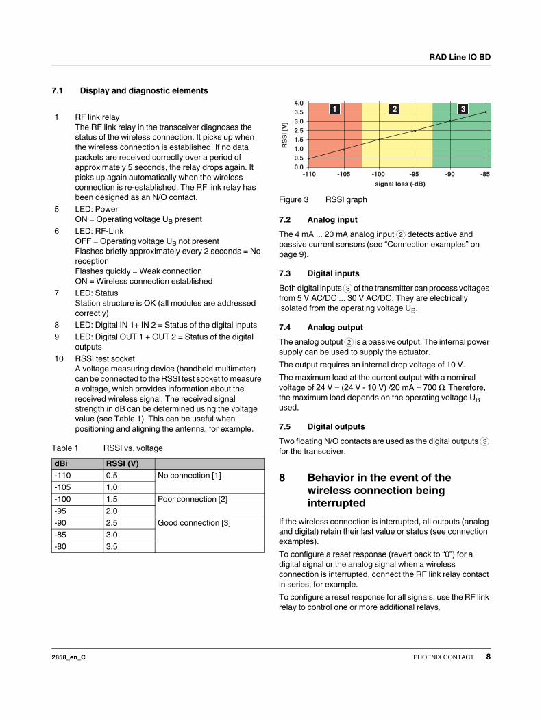
7.1 Display and diagnostic elements
Figure 3 RSSI graph
7.2 Analog input
The 4 mA ... 20 mA analog input 2 detects active and
passive current sensors (see “Connection examples” on
page 9).
7.3 Digital inputs
Both digital inputs 3 of the transmitter can process voltages
from 5 V AC/DC ... 30 V AC/DC. They are electrically
isolated from the operating voltage UB.
7.4 Analog output
The analog output 2 is a passive output. The internal power
supply can be used to supply the actuator.
The output requires an internal drop voltage of 10 V.
The maximum load at the current output with a nominal
voltage of 24 V = (24 V - 10 V) /20 mA = 700 Ω. Therefore,
the maximum load depends on the operating voltage UB
used.
7.5 Digital outputs
Two floating N/O contacts are used as the digital outputs 3
for the transceiver.
8 Behavior in the event of the
wireless connection being
interrupted
If the wireless connection is interrupted, all outputs (analog
and digital) retain their last value or status (see connection
examples).
To configure a reset response (revert back to “0”) for a
digital signal or the analog signal when a wireless
connection is interrupted, connect the RF link relay contact
in series, for example.
To configure a reset response for all signals, use the RF link
relay to control one or more additional relays.
1 RF link relay
The RF link relay in the transceiver diagnoses the
status of the wireless connection. It picks up when
the wireless connection is established. If no data
packets are received correctly over a period of
approximately 5 seconds, the relay drops again. It
picks up again automatically when the wireless
connection is re-established. The RF link relay has
been designed as an N/O contact.
5 LED: Power
ON = Operating voltage UB present
6 LED: RF-Link
OFF = Operating voltage UB not present
Flashes briefly approximately every 2 seconds = No
reception
Flashes quickly = Weak connection
ON = Wireless connection established
7 LED: Status
Station structure is OK (all modules are addressed
correctly)
8 LED: Digital IN 1+ IN 2 = Status of the digital inputs
9 LED: Digital OUT 1 + OUT 2 = Status of the digital
outputs
10 RSSI test socket
A voltage measuring device (handheld multimeter)
can be connected to the RSSI test socket to measure
a voltage, which provides information about the
received wireless signal. The received signal
strength in dB can be determined using the voltage
value (see Table 1). This can be useful when
positioning and aligning the antenna, for example.
Table 1 RSSI vs. voltage
dBi RSSI (V)
-110 0.5 No connection [1]
-105 1.0
-100 1.5 Poor connection [2]
-95 2.0
-90 2.5 Good connection [3]
-85 3.0
-80 3.5
signal loss (-dB)
RS
SI [
V]
1 2 3
0.51.01.52.53.03.54.0
0.0-110 -105 -100 -95 -90 -85

RAD Line IO BD
2858_en_C PHOENIX CONTACT 9
9 Connection examples
9.1 Transceiver 1 and transceiver 2 for hold response of all outputs
Both transceivers have the same structure.
Figure 4 Transceiver 1 and transceiver 2 for hold response of all outputs
POWER
DIGITAL
RSSI
RF LINK
DIGITAL
IN 1 IN 2
OUT 1 OUT 2
1A 1B 2A 2B
1A 1B 2A 2B
STATUS
4-20mA-LoopINOUT
A B
+ - + -
+UBGND
RF-Link
+24V
COM
5...30 VAC/DC
A
OUT1
GND
+24V
GND +24V
GND
+24V
IN1
IN2
GND
4...20 mA
OUT2
4...20 mA
-
+
POWER
DIGITAL
RSSI
RF LINK
DIGITAL
IN 1 IN 2
OUT 1 OUT 2
1A 1B 2A 2B
1A 1B 2A 2B
STATUS
4-20mA-LoopINOUT
A B
+ - + -
+UBGND
RF-Link
+24V
COM
5...30 VAC/DC
A
OUT1
GND
+24V
GND +24V
GND
+24V
IN1
IN2
GND
4...20 mA
OUT2
4...20 mA
-
+
Active current sensor Active current sensor

RAD Line IO BD
2858_en_C PHOENIX CONTACT 10
9.2 Transceiver 1 and transceiver 2 for reset response of the digital outputs
Figure 5 Transceiver 1 and transceiver 2 for reset response of the digital outputs
POWER
DIGITAL
RSSI
RF LINK
DIGITAL
IN 1 IN 2
OUT 1 OUT 2
1A 1B 2A 2B
1A 1B 2A 2B
STATUS
4-20mA-LoopINOUT
A B
+ - + -
+UBGND
+24V
COM
5...30 VAC/DC
A
OUT1
GND
+24V
GND +24V
GND
IN1
IN2
GND
4...20 mA
OUT2
4...20 mA
-
+
POWER
DIGITAL
RSSI
RF LINK
DIGITAL
IN 1 IN 2
OUT 1 OUT 2
1A 1B 2A 2B
1A 1B 2A 2B
STATUS
4-20mA-LoopINOUT
A B
+ - + -
+UBGND
+24V
COM
5...30 VAC/DC
A
OUT1
GND
+24V
GND +24V
GND
IN1
IN2
GND
4...20 mA
OUT2
4...20 mA
-
+
Active current sensor Active current sensor

RAD Line IO BD
2858_en_C PHOENIX CONTACT 11
9.3 Transceiver 1 and transceiver 2 for reset response of the analog outputs
Figure 6 Transceiver 1 and transceiver 2 for reset response of the analog outputs
POWER
DIGITAL
RSSI
RF LINK
DIGITAL
IN 1 IN 2
OUT 1 OUT 2
1A 1B 2A 2B
1A 1B 2A 2B
STATUS
4-20mA-LoopINOUT
A B
+ - + -
+UBGND
COM
5...30 VAC/DC
A
OUT1
GND
+24V
GND +24V
GND
IN1
IN2
GND
4...20 mA
OUT2
4...20 mA
-
+
POWER
DIGITAL
RSSI
RF LINK
DIGITAL
IN 1 IN 2
OUT 1 OUT 2
1A 1B 2A 2B
1A 1B 2A 2B
STATUS
4-20mA-LoopINOUT
A B
+ - + -
+UBGND
COM
5...30 VAC/DC
A
OUT1
GND
+24V
GND +24V
GND
IN1
IN2
GND
4...20 mA
OUT2
4...20 mA
-
+
+24V +24V
Active current sensor Active current sensor

RAD Line IO BD
2858_en_C PHOENIX CONTACT 12
9.4 Transceiver 1 and transceiver 2 for connection of a passive current sensor with 2-wire connection method
Figure 7 Transceiver 1 and transceiver 2 for connection of a passive current sensor with 2-wire connection method
POWER
DIGITAL
RSSI
RF LINK
DIGITAL
IN 1 IN 2
OUT 1 OUT 2
1A 1B 2A 2B
1A 1B 2A 2B
STATUS
4-20mA-LoopINOUT
A B
+ - + -
+UBGND
+24V
4...20 mA
POWER
DIGITAL
RSSI
RF LINK
DIGITAL
IN 1 IN 2
OUT 1 OUT 2
1A 1B 2A 2B
1A 1B 2A 2B
STATUS
4-20mA-LoopINOUT
A B
+ - + -
+UBGND
A
GND
+24V
GND
+24V
Passive current sensor

RAD Line IO BD
2858_en_C PHOENIX CONTACT 13
9.5 Transceiver 1 and transceiver 2 for connection of a passive current sensor with 3-wire connection method
Figure 8 Transceiver 1 and transceiver 2 for connection of a passive current sensor with 3-wire connection method
POWER
DIGITAL
RSSI
RF LINK
DIGITAL
IN 1 IN 2
OUT 1 OUT 2
1A 1B 2A 2B
1A 1B 2A 2B
STATUS
4-20mA-LoopINOUT
A B
+ - + -
+UBGND
+24V
4...20 mA
POWER
DIGITAL
RSSI
RF LINK
DIGITAL
IN 1 IN 2
OUT 1 OUT 2
1A 1B 2A 2B
1A 1B 2A 2B
STATUS
4-20mA-LoopINOUT
A B
+ - + -
+UBGND
AGND
+24V
GND
GND
+24V
GND
+24V
Passive current sensor

RAD Line IO BD
2858_en_C PHOENIX CONTACT 14
10 I/O expansion module connection
examples
10.1 RAD-IN-4A-I
Figure 9 Connection example for the RAD-IN-4A-I
10.2 RAD-OUT-4A-I
Figure 10 Connection example for the RAD-OUT-4A-I
STATUS
RAD-IN-4A-I
Module
1 2
3
45
6
78
4-20mA-LoopIn 1
- +
- +
4-20mA-LoopIn 2
POWER OUTGND +24V
POWER OUTGND +24V
4-20mA-LoopIn 3
4-20mA-LoopIn 4
POWER OUT+ - +24V GND
POWER OUT+ - +24V GND
4...20 mA
GND
+24V
GND
4...20 mA
24V
GND
4...20 mA
24V
STATUS
RAD-OUT-4A-I
Module
1 2
3
45
6
78
4-20mA-LoopOut 1
- +
- +
4-20mA-LoopOut 2
POWER OUTGND +24V
POWER OUTGND +24V
4-20mA-LoopOut 3
4-20mA-LoopOut 4
POWER OUT+ - +24V GND
POWER OUT+ - +24V GND
A
A
24V

RAD Line IO BD
2858_en_C PHOENIX CONTACT 15
10.3 RAD-IN-8D
Figure 11 Connection example for the RAD-IN-8D
10.4 RAD-OUT-8D-REL
Figure 12 Connection example for the RAD-OUT-8D-
REL
24 V
GND
24 V
24 V
24 V
IN5
IN6
IN7
IN8
DIGITAL
DIGITAL
IN 5 IN 6
IN 7 IN 8
5A 5B 6A 6B
7A 7B 8A 8B
STATUS
RAD-IN-8D
Module
1 2
3
45
6
78
DIGITALIN 1 IN 2
1A 1B 2A 2B
DIGITALIN 3 IN 4
3A 3B 4A 4B
DIGITAL
DIGITAL
OUT 5 OUT 6
OUT 7 OUT 8
5A 5B 6A 6B
7A 7B 8A 8B
STATUS
RAD-OUT-8D-REL
Module
1 2
3
45
6
78
DIGITALOUT 1 OUT 2
1A 1B 2A 2B
DIGITALOUT 3 OUT 4
3A 3B 4A 4B
30 V DC/30 V AC

RAD Line IO BD
2858_en_C PHOENIX CONTACT 16
10.5 RAD-IN+OUT-2D-1A-I
Figure 13 Digital input connection example for the
RAD-IN+OUT-2D-1A-I
Figure 14 Digital output connection example for the
RAD-IN+OUT-2D-1A-I
10.6 RAD-IN-2D-CNT
Figure 15 Open collector example for the
RAD-IN-2D-CNT
Recommended DIP switch settings:
– DIP 1 "Coupling": DC
– DIP 2 "Impedance": LOW
– DIP 3 "Operation Mode": Depending on the application:
either in counter or in frequency mode
– DIP 4 "Speed": Depending on the application: if the
pulse length of the pulses to be measured is at least
100 ms or greater, the low pass filter can be activated
(DIP to low) to suppress interference. If you are
measuring shorter signal lengths, set the DIP switch to
high.
– DIP 5 "Sensor Input": Single ended
Figure 16 Optocoupler or relay example for the
RAD-IN-2D-CNT
Recommended DIP switch settings:
– Same as for the Open collector example (see
Figure 15).
STATUS
RAD-IN+OUT-2D-1A-I
Module
1 2
3
45
6
78
4-20mA-LoopOut 1
- +
- +
4-20mA-LoopIn 1
GND +24V
GND +24V
DIGITAL
DIGITAL
IN 1 IN 2
OUT 1 OUT 2
1A 1B 2A 2B
1A 1B 2A 2B
POWER OUT
POWER OUT
24 V
24 VGND
IN1
IN2
A
4...20 mA
GND
+24V
GND
Internal power
supply
Digital inputs
Active sensor
STATUS
RAD-IN+OUT-2D-1A-I
Module
1 2
3
45
6
78
4-20mA-LoopOut 1
- +
- +
4-20mA-LoopIn 1
GND +24V
GND +24V
DIGITAL
DIGITAL
IN 1 IN 2
OUT 1 OUT 2
1A 1B 2A 2B
1A 1B 2A 2B
POWER OUT
POWER OUT
30 V DC/30 V AC
A
+24 V
4...20 mA
+24 V
External power
supply
Passive sensor
(2-wire)
Digital outputs
STATUS
Pulse In 1
Backup Power
GND
RAD-IN-2D-CNT
+24V NC NC
12
3
45
6
7
8
Module
DCLowFrequencyHigh
Single Ended
VCC
Open Collector
STATUS
Pulse In 1
Backup Power
GND
RAD-IN-2D-CNT
+24V NC NC
12
3
45
6
7
8
Module
PowerAC
24V DCDCLowFrequencyHigh
Single Ended

RAD Line IO BD
2858_en_C PHOENIX CONTACT 17
For relay applications:
– Set DIP 4 “Speed” to low to compensate for contact
chatter.
Figure 17 Magnetic measuring transducer for the
RAD-IN-2D-CNT
Recommended DIP switch settings:
– DIP 1 "Coupling": DC
– DIP 2 "Impedance": HIGH
– DIP 3 "Operation Mode": Depending on the application:
either in counter or in frequency mode
– DIP 4 "Speed": HIGH
– DIP 5 "Sensor Input": Differential mode
10.7 RAD-OUT-2D-CNT
Switched load
The integrated transistor in the module output can switch
loads, such as relays or optocouplers. A self-resetting fuse
protects the transistor against damage due to short circuit.
The switch position of the DIP switches should be selected
according to the application as described in DIP switches.
Figure 18 Passive load with an optocoupler for the
RAD-OUT-2D-CNT
Figure 19 Passive load with a relay for the
RAD-OUT-2D-CNT
Figure 20 External power supply load with an
optocoupler for the RAD-OUT-2D-CNT
Figure 21 External power supply load with an
optocoupler for the RAD-OUT-2D-CNT
STATUS
Pulse In 1
Backup Power
GND
RAD-IN-2D-CNT
+24V NC NC
12
3
45
6
7
8
Module
DCHighFrequencyHigh
Differential Mode
24 V Power OUT
EXT IN 1
GND
1,1kΩ
4
3
2
1
OUT 1
Power
Load RAD-OUT-2D-CNT
24 V Power OUT
EXT IN 1
GND
1,1kΩ
4
3
2
1
OUT 1
Power
Load RAD-OUT-2D-CNT
24 V Power OUT
EXT IN 1
GND
1,1kΩ
4
3
2
1
OUT 1
PowerVCC( 30 V DC)
GND
Load RAD-OUT-2D-CNT
24 V Power OUT
EXT IN 1
GND
1,1kΩ
4
3
2
1
OUT 1
PowerVCC
GND
Load RAD-OUT-2D-CNT

RAD Line IO BD
2858_en_C PHOENIX CONTACT 18
Voltage output for subsequent control systems
If the downstream electronics requires a HIGH/LOW voltage
level, the required communications power can be
connected to the EXT terminal block. The logic ground must
also be connected to the module ground (OUT GND
terminal block). The HIGH/LOW signal can then be picked
up at the OUT terminal block.
The switch position of the DIP switches should be selected
according to the application.
Figure 22 Voltage output for subsequent control
systemas for the RAD-OUT-2D-CNT
10.8 Avoiding ground loops
Figure 23 shows the course of the compensating currents, which is created when different supply voltage sources are used
for the sensor and the RAD-ISM-... device, and when the two sources have a separate ground reference. This arrangement
(using different sources for sensor and RAD-ISM-... system) does not always cause problems. However, high compensating
24 V Power OUT
EXT IN 1
GND
1,1kΩ
4
3
2
1
OUT 1
Power
VCC(5...30 V DC)
GND
Load RAD-OUT-2D-CNT
NOTE: Device damage caused by compensating currents
Differential voltages may occur between the potentials when the ground connections are physically separated.
These voltages may cause compensating currents over the low-resistance path marked in red. Just a few volts can
cause compensating currents in the range of several amperes, which may damage the device.

RAD Line IO BD
2858_en_C PHOENIX CONTACT 19
currents (in the range of several amperes) may cause damage to the device. To avoid these effects, the complete
arrangement must only be grounded at one central point (e.g., not using the connection to PE2).
Figure 23 Avoiding ground loops
POWER
DIGITAL
RSSI
RF LINK
DIGITAL
IN 1 IN 2
OUT 1 OUT 2
1A 1B 2A 2B
1A 1B 2A 2B
STATUS
4-20mA-Loop
INOUT
A B
+ - + -
+UBGND
24 V DC 24 V DC
GND
PE1
GND
PE2
GNDUBGNDOUT
Internal connection with
current-compensated choke
4 mA ... 20 mA sensor
Output with external
supply
Internal connection
Compensating currents
Differential voltages between the potentials

RAD Line IO BD
2858_en_C PHOENIX CONTACT 20
10.9 Installation in hazardous locations
With certification according to UL, the RAD-ISM-900-SET…BUS… bidirectional wireless system can be used in the
hazardous area of division 2 with hazardous gases. Signals from outside the hazardous area as well as signals from division
2 can be connected directly. Signals from zones 1 and 0 cannot be connected directly. They can only be connected via the
appropriate barriers because the inputs are not intrinsically safe.
Figure 24 RAD-ISM-900-SET…BUS… with UL/cUL approval for use in Class I, Division 2 areas
POWER
DIGITAL
RSSI
RF LINK
DIGITAL
IN 1 IN 2
OUT 1 OUT 2
1A 1B 2A 2B
1A 1B 2A 2B
STATUS
4-20mA-LoopINOUT
A B
+ - + -
+UBGND
Division 1
Division 2
POWER
DIGITAL
RSSI
RF LINK
DIGITAL
IN 1 IN 2
OUT 1 OUT 2
1A 1B 2A 2B
1A 1B 2A 2B
STATUS
4-20mA-LoopINOUT
A B
+ - + -
+UBGND
4 mA ... 20 mA
sensor
Not directly but via
barrier
Wireless path through
Division 1: OK
4 mA ... 20 mA
sensor
4 mA ... 20 mA
sensor

RAD Line IO BD
2858_en_C PHOENIX CONTACT 21
10.10 Point-to-point
Point-to-point
In the point-to-point system version, the set is installed, the
signals are connected, and the operating voltage is applied.
The wireless connection is established automatically - no
other settings are required.
Figure 25 Point-to-point
Point-to-point with extension modules
When extension modules are used, they are mounted via the
bus foot on the side. A maximum of eight extension modules
can be mounted. The modules are assigned to one another
via an address encoding switch on the front of the module.
Please note, for example, that an 8-channel digital input
module (RAD-IN-8D) (module 1 in Figure 26) is assigned to
an 8-channel digital output module (RAD-OUT-8D-REL)
(module a in Figure 26) on the other station side (→ same
address). The status LED indicates whether the system
structure is correct (ON = OK; flashing = error).Figure 26 Point-to-point with extension modules
Point-to-multipoint
For a bidirectional point-to-multipoint system, use the RAD-
ISM-900-SET-XD (Order No. 5605715).
Figure 27 Point-to-multipoint
Transceiver Transceiver
Transceiver Transceiver
1T 2 3 4 aT b c d
Transmitter Receiver

RAD Line IO BD
2858_en_C PHOENIX CONTACT 22
11 Hopkey
11.1 Replacement
The HOPKEY (Order No. 2867539) must be replaced when
replacing faulty transceivers or when extending a system to
create multi-receiver or repeater systems.
To order a HOPKEY, the HOPKEY ID and serial numbers of
the existing devices must be supplied along with the disired
HOPKEY type, i.e., master, repeater, slave.
The HOPKEY contains information such as the
transmission frequencies used and the hop sequence. This
information is required when installing an additional
receiver/repeater in an existing system.
To install a HOPKEY, proceed as follows:
1. To protect the modules against ESD, the operating
personnel must remove electrostatic discharge at
appropriate points (e.g., control cabinet) before
touching the modules.
2. The existing system must have established a wireless
connection.
3. Disconnect the power to the existing system.
4. Open the housing of the transceiver in the existing
system by pressing both housing latches on the sides.
Remove the electronics module from the housing (see
Figure 30).
5. At the bottom right on the PCB is a small PCB in a
10-pos. base – this is the HOPKEY. Remove the
HOPKEY and insert it in the same position in the new
transceiver that you wish to install (see Figure 31).
Repeater system
Repeaters can be used to overcome large obstacles
(e.g., mountain tops) or to increase the range.
Repeaters are simple transceivers with a special HOPKEY.
To extend an existing point-to-point system with a repeater,
an additional transceiver (RAD-ISM-900-BD-BUS,
Order No. 2867092) and a HOPKEY with repeater
configuration are required for the existing set.
Figure 28 Repeater system
Multi-repeater system
Any number of repeaters can be integrated in one system.
Please note that the cycle time increases by 37 ms for each
repeater.
Example: In the figure opposite, a signal requires at least
4 x 37 ms to go from A to B and just as long to come back
again. A complete system update, therefore, takes at least
8 x 37 ms.
Figure 29 Multi-repeater system
Important: Bidirectional data exchange is also
possible with extension modules in a point-to-
point connection with a repeater.
Signals cannot be detected or output at the
repeater. The cycle time when transmitting in one
direction doubles from 37 ms to 74 ms.Transceiver Transceiver
Receiver
Receiver
A B

RAD Line IO BD
2858_en_C 23PHOENIX CONTACT GmbH & Co. KG • 32823 Blomberg • Germany
www.phoenixcontact.com
6. Close all the housing covers and reinsert the modules in
the control cabinet(s).
7. Reconnect the supply voltage – the new transceiver
now also operates in the existing system.
8. Repeat the procedure for all additional
receivers/repeaters.
Explanation:
When the supply voltage is connected, the information is
transmitted from the connected HOPKEY to a non-volatile
memory inside the module. This HOPKEY can then be used
to "teach" other receivers. The HOPKEY can be stored in
the last receiver.
If no HOPKEY is connected, the information inside the
module is used.
Figure 30 Removing the electronics module
Figure 31 Inserting the HOPKEY
11.2 HOPKEY replacement applications
Replacing a faulty transceiver in a point-to-point
system
If a faulty transceiver has to be replaced, only one
replacement module (RAD-ISM-900-SET-BD-BUS,
Order No. 2867092) is required.
• Remove the HOPKEY from the faulty module and insert
it in the replacement device. The system continues to
operate after switching on the supply voltage.
If a HOPKEY is ever lost in a point-to-point system, an
appropriate replacement can be ordered as follows. Check
whether "M" or "S" is specified next to the identification
number (ID) on the HOPKEY. In a point-to-point system,
one HOPKEY with "IDxxxxxM" and one HOPKEY with
"IDxxxxxS" must always be available. Order as follows:
Repeater function in the point-to-point system
If an existing point-to-point system is to be extended by one
or more repeaters, at least one transceiver
(Order No. 2867092) is required for your RAD-ISM-900-
SET-BD-BUS, as well as the following HOPKEY:
The HOPKEY is installed in the additional transceiver. If
additional repeaters are used, the HOPKEY is replaced by
the additional transceivers one after the other.
OMNEXHOPKEY
Type Order
No.
Pcs./
Pkt.
Additional
ordering data
RAD-ISM-900-HOP-US 2867539 1 IDxxxxx,
PPM = Type M
Type Order
No.
Pcs./
Pkt.
Additional
ordering data
RAD-ISM-900-HOP-US 2867539 1 IDxxxxx,
REP = Type
OMNEXHOPKEY