r3-a.1: millimeter wave whole body scanning radar … millimeter wave whole body scanning radar...
TRANSCRIPT
R3-A.1: Millimeter Wave Whole Body Scanning
Radar Hardware for Advanced Imaging
Technology (AIT)
Abstract—The second phase of the Advanced Imaging Technology project is divided into hardware research (R3-A.1, this report), and algorithm research (R3-A.2, following report). The two parts work together to develop an improved multi-modality, portal-based passenger screening system. Millimeter-wave (mm-wave) scanning and x-ray backscatter, supplemented by Kinnect surface depth mapping, have been implemented. The 56-64 GHz mm-wave imaging system has produced several hardware and data processing innovations. These include: a second generation Blade Beam refl ector transmitting antenna that produces narrow target illumination to allow accurate stacked 2D reconstructions of the 3D surface; a carefully positioned multistatic, array receiving antenna for artifact-free imaging; and a fast data processing technique, based on the Fast Multipole Method (FMM) that produces 2D SAR images from scattered fi eld samples. The specially-built hardware platform facilitates reconfi gurable sensor placement in order to develop the multistatic imaging ra-dar system. In addition, a patent-pending algorithm for determining the dielectric constant of weak dielectric objects attached to the body – has been developed under R3-A.2 and tested in this project, and is now ready for transition to industry as part of a proposed DHS Task Order contract. These improvements lead to faster, more accurate whole body imaging to improve the security screening process, with proved detection capabilities validated by means of measurements carried out with a fi rst mm-wave portal prototype.
I. PARTICIPANTS
Faculty/Staff
Name Title Institution Email
Carey Rappaport Co-PI NEU [email protected]
Jose Martinez Co-PI NEU [email protected]
Borja Gonzalez-Valdes Post-Doc NEU [email protected]
Yuri Alvarez Visiting Faculty NEU [email protected]
Richard Moore Consultant MGH [email protected]
Dan Busuioc Consultant NEU [email protected]
Students
Name Degree Pursued Institution Intended Year of Graduation
Matthew Nickerson BS NEU 5/2016
Nigil Lee BS NEU 5/2017
Scott Pitas BS NEU 5/2015
Tiphanie Zeng BS NEU 5/2016
Thurston Brevett BS NEU 5/2018
Michael Woulfe BS NEU 5/2018
Matthew Tivnan BS NEU 5/2017
ALERT Phase 2 Year 1 Annual Report
Appendix A: Project Reports Thrust R3: Bulk Sensors and Sensor Systems
Project R3-A.1
II. PROJECT OVERVIEW AND SIGNIFICANCE
As people enter secure areas, it is important that they be scanned to ensure that they are not entering with weapons or explosives. In addition to airport departure gates; of ice buildings, stadiums and arenas must have fast, accurate, non-intrusive means of detecting threats concealed under clothing.The Whole Body Imaging project is developing an improved multi-modality, portal-based passenger screen-ing system. Millimeter-wave (mm-wave), infrared and low frequency microwave sensing are methods being pursued. The 56-64 GHz mm-wave imaging system includes: a patented Blade Beam re lector transmitting antenna that produces narrow target illumination to allow accurate stacked 2D reconstructions of the 3D surface; a multistatic array receiving antenna for artifact-free imaging; and a fast reconstruction algorithm that signi icantly outperforms conventional Synthetic Aperture Radar processing. The specially-built hard-ware platform facilitates recon igurable multi-sensor con igurations. With X-ray backscatter systems becoming less favored by the traveling public, especially in Europe, high reso-lution human body imaging has fallen to mm-wave imaging and detection. Mm-waves pass though clothing readily, but can identify dangerous objects attached to the body. Current state-of-the-art millimeter wave portal imaging systems are mostly based on monostatic radar. Although these systems are inherently fast, they present some disadvantages, including reconstruction artifacts, such as dihedral effects and misrepre-senting sudden indentations and protrusions due to the monostatic nature of the collected electric ield data, and a lack of quantitative range of depth information display. For practical 3D human body screening, real-time capabilities are required, so fast methods for geometry reconstruction are needed. The system that has been developed under ALERT support is based on fast mul-tistatic Synthetic Radar Aperture (SAR) imaging and introduces several new contributions to the ield of mil-limeter wave imaging.
III. RESEARCH ACTIVITY
A. State-of-the-art and technical approach and major contribution
Three signi icant technological advances have been pursued in the past year in the AIT hardware devel-opment project: modularized mm-wave radar electronics realization, new elliptical torus re lector design for multistatic broadband blade beam illumination and successful experimentation with low-loss dielectric slabs af ixed to the body.
A.1 Modularized mm-wave electronics
The millimeter-wave imaging system was designed around a low-cost, highly-integrated, wide-bandwidth, transceiver chipset as described in [1]. A block diagram of the system is shown in Figure 1, with black lines representing signal lines, red trigger lines, orange clock lines and blue control lines. The transceiver chipset was designed for high-speed, indoor, wireless communication using the unlicensed 60 GHz band. The chipset provides 8 GHz of bandwidth split into 16 separate 500 MHz bands in the range 56.5–64.5 GHz. The entire bandwidth is covered with a baseband input signal in the range 5–550 MHz. Although the transceiver chip-set was not intended for use in millimeter-wave imaging, with appropriate modi ication, it can function as a wideband stepped-frequency radar: i) The transmitter and receiver operate on a common clock; ii) Both the transmitted and received signals are sampled; and iii) A phase coherence mechanism is used to combine the 16 separate 500 MHz bands into 8 GHz of imaging bandwidth. The notable aspect of this novel design (with provisional patent) is that the clock signal – shown in orange – carries relatively low frequency signals, and therefore can use long lengths of standard, lexible cable, thereby allowing the transmitters and receivers to be widely separated for multistatic radar operation. The design, realized with component hardware, was
ALERT Phase 2 Year 1 Annual Report
Appendix A: Project Reports Thrust R3: Bulk Sensors and Sensor Systems
Project R3-A.1

built, tested and proved to be effective in the previous year.Progress in the past year has resulted in an RF printed circuit board custom design as seen in Figure 2a and realization, Figure 2b. As shown in Table 1, besides size advantages, the printed circuit version offers signi icant cost reduction. Since the eventual full mm-wave radar sys-tem will require multiple channels for multiple views, it may employ as many as 32 receivers. Reducing the cost per receiver from $23.5K to $160 brings the total receiver cost down from a prohibitive $752K to about $5K (with comparable cost reductions for the transmitters). In addition, the Hittite transceiver chip [2] incorporates an integrated wide-beam antenna (shown in the lower right corner in Figs. 2a and 2b). The PC board will be mounted with the integrated antenna posi-tioned in the feed region of the new torus re lector (discussed in the next section). This will eliminate the need for expensive, heavy and dispersive waveguide, and since the antenna is in the board corner, the boards can be packed closely, overlapping 80% of an adjacent card.
Hybrid PC proto-
type
PC pro-
duction
Notes
RF and μwave
components
$12,000 $128 $25 Hittite chip with integrated antenna
Supporting electronics:
power supply, control
$200 – 500 $90 $10 Low-volume to high-volume cost ratio 10:1
Mechanical >$500 $25 $5 Hybrid uses high precision mechanical
supports, etc.
Digitizer electronics $10,000 $1,000 <$100 Use integrated TI digitizer on-board for
production
Cabling $300 – 500 $50 <$10 Hybrid precision-matched
Total cost $23,500 ~ $1,275* < $160* *Cost driven by digitizer
Figure 1: Block layout of a single
channel of the novel multistatic mm-
wave imaging radar.
a) b)
Figure 2: Custom designed PC board with Hittite transceiver chip: a) Multilayer PC layout (left), and b) PC component
placement on board (right).
Table 1: Cost comparison for original, second generation PC prototype and production version estimates.
ALERT Phase 2 Year 1 Annual Report
Appendix A: Project Reports Thrust R3: Bulk Sensors and Sensor Systems
Project R3-A.1

A.2 New elliptical torus re lector design for multistatic broadband blade beam illumination
The irst phase of this ALERT project conceived and demonstrated the effectiveness of the Blade Beam re lec-tor to illuminate narrow sections of a subject, facilitating ef icient high resolution processing of body con-tours. The second phase has now been building on the lessons learned from Phase 1. In particular, it was de-termined that the near ield mm-wave imaging of large convex objects, such as a human torso, is much more dependent on specular ray paths than previously thought. No amount of focusing can overcome the effects of glancing incidence. If representative rays re lect from an object in directions with no receiving antennas, no ield will be observed. Armed with this realization, it became clear that a single transmitter, even one with as carefully tailored illumination as the Blade Beam elliptical/parabolic re lector, cannot effectively probe the entire front of a torso. To accomplish this complete imaging requirement, multiple incident directions of transmittance are needed. Either multiple re lectors had to be used, or a new design is necessary.The current novel re lector design borrows from satellite re lector concepts by blending multiple individual re lector surfaces into a single large section of a torus; circular in the horizontal plane and offset elliptical in the vertical plane. Because of the elliptical vertical pro ile, the torus re lects rays from the system feed to a second focus at the target object; and with the appropriate choice of offset and circle radius, the rays can be made to be essentially parallel in the horizontal plane (for any given feed position). Thus, this surface piecewise approximates the previously developed Blade Beam surface. Figure 3a shows the torus re lector with the two foci in the plane of symmetry. Figure 3b is a top view of this re lector, indicating in blue the arc of possible feed locations. Note that the feed focus lies in the plane which contains the bottom edge of the torus, while the target focus is in the plane of the ellipse vertex (furthest point to the left), and that the center of rotation is at (x, y) = (0, 0).
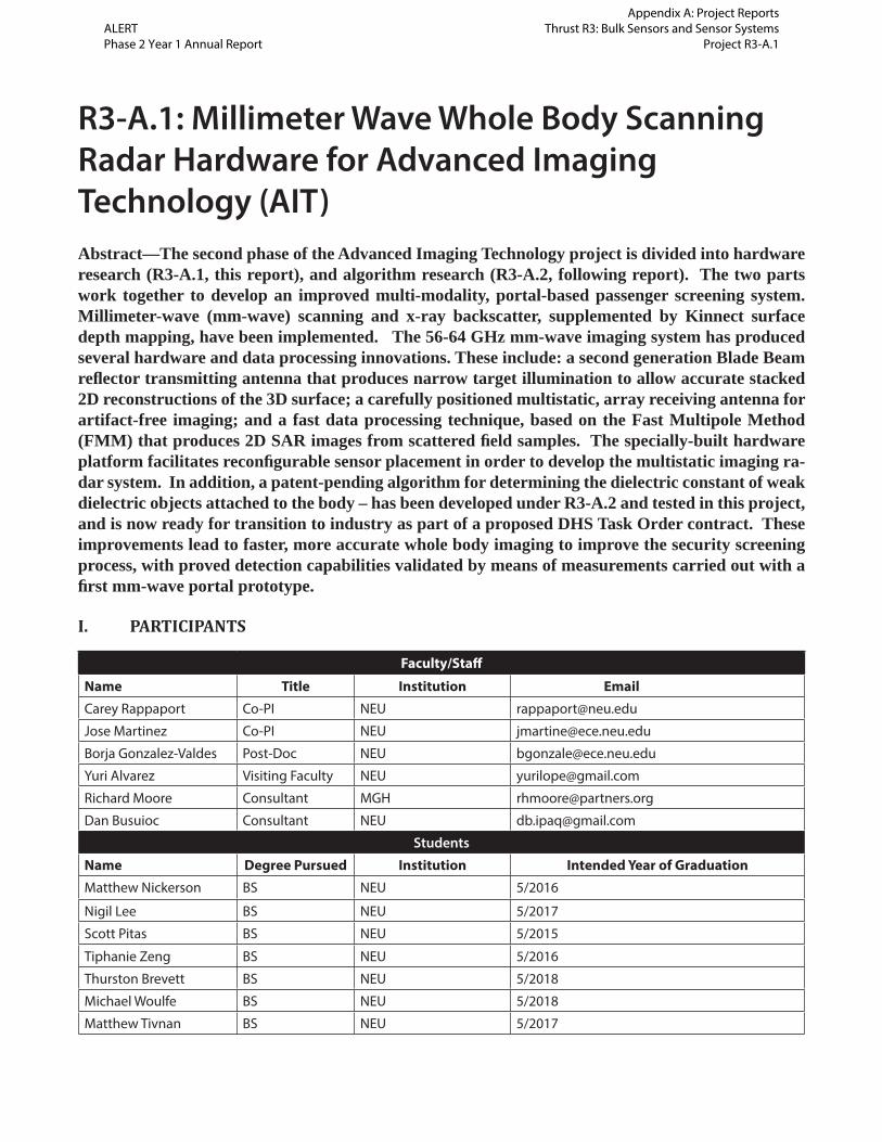
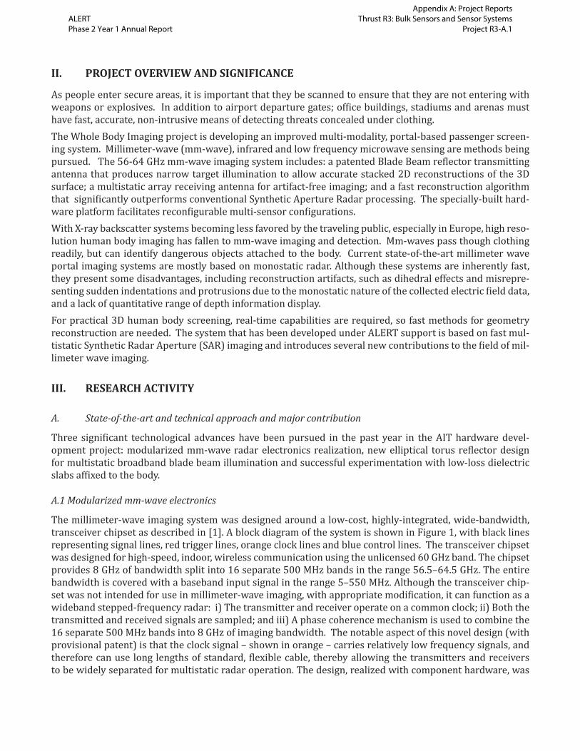
By circular symmetry, any feed on the feed arc will generate the same set of re lected rays tilted by the angle of the feed from (0, 0) relative to the y-axis. Figure 4a on the next page shows the top view of the re lector numerically illuminated by a feed in the central position, and Figure 4b on the next page shows a perspec-tive view, also indicating the ield on the torso target. Only the central section of the re lector is illuminated, but the torso is almost entirely illuminated from side to side, and the illumination is very narrow vertically. Figure 5 on the next page shows the illumination when the feed is positioned on the feed arc at 45 degrees relative to the y-axis. Only the right side of the re lector is illuminated, and the right side of the torso is illumi-nated by a similar blade beam. Because the rays in this case are inclined 30 deg. in azimuth, most of them will re lect back to the re lector, rather than forward, away from the antenna; fewer specular rays will be missed.
a) b)
Figure 3: Off set elliptical torus refl ector: a) perspective view (left) and b) top view (right).
ALERT Phase 2 Year 1 Annual Report
Appendix A: Project Reports Thrust R3: Bulk Sensors and Sensor Systems
Project R3-A.1
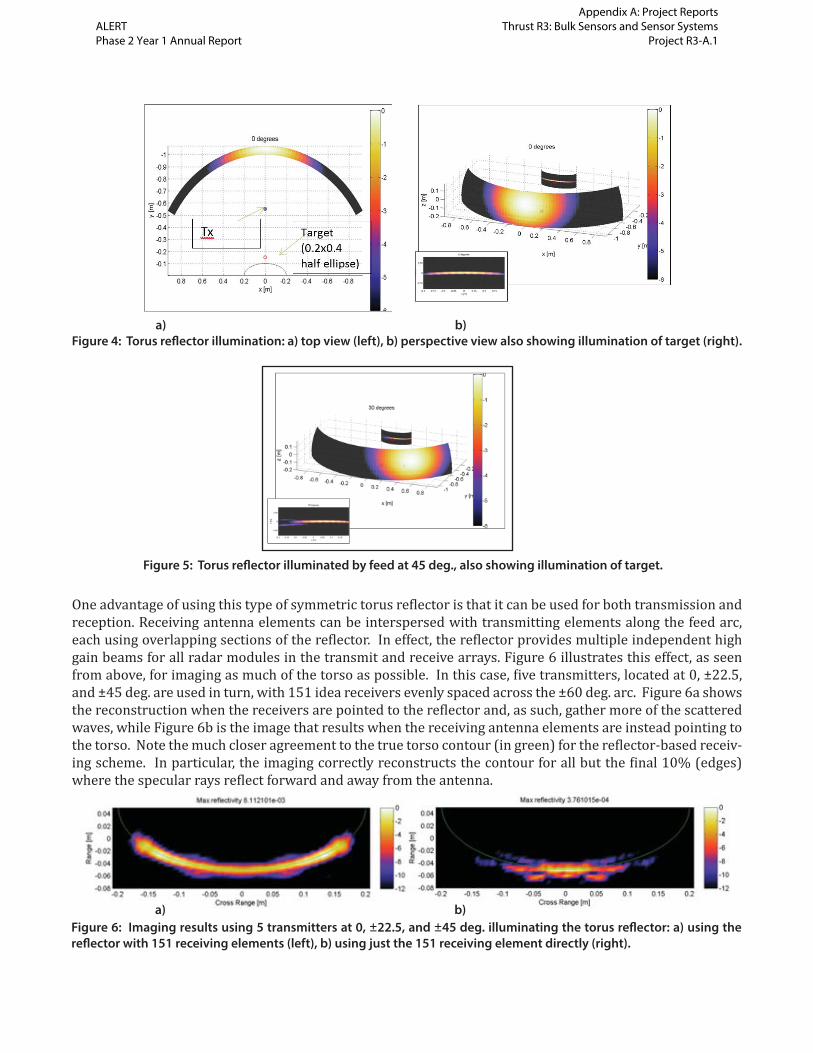
One advantage of using this type of symmetric torus re lector is that it can be used for both transmission and reception. Receiving antenna elements can be interspersed with transmitting elements along the feed arc, each using overlapping sections of the re lector. In effect, the re lector provides multiple independent high gain beams for all radar modules in the transmit and receive arrays. Figure 6 illustrates this effect, as seen from above, for imaging as much of the torso as possible. In this case, ive transmitters, located at 0, ±22.5, and ±45 deg. are used in turn, with 151 idea receivers evenly spaced across the ±60 deg. arc. Figure 6a shows the reconstruction when the receivers are pointed to the re lector and, as such, gather more of the scattered waves, while Figure 6b is the image that results when the receiving antenna elements are instead pointing to the torso. Note the much closer agreement to the true torso contour (in green) for the re lector-based receiv-ing scheme. In particular, the imaging correctly reconstructs the contour for all but the inal 10% (edges) where the specular rays re lect forward and away from the antenna.
a) b)
Figure 4: Torus refl ector illumination: a) top view (left), b) perspective view also showing illumination of target (right).
Figure 5: Torus refl ector illuminated by feed at 45 deg., also showing illumination of target.
a) b)
Figure 6: Imaging results using 5 transmitters at 0, ±22.5, and ±45 deg. illuminating the torus refl ector: a) using the
refl ector with 151 receiving elements (left), b) using just the 151 receiving element directly (right).
ALERT Phase 2 Year 1 Annual Report
Appendix A: Project Reports Thrust R3: Bulk Sensors and Sensor Systems
Project R3-A.1

One open area of research is the choice of number and best positions of the receiving and transmitting ele-ments. The resolution of the reconstructed image is proportional to the combination of the point spread function (PSF) of the transmitter and the receiver. If the nulls of one line up with the sidelobes of the other, the image becomes clearer. Array periodicity tends to produce grating lobe artifacts, so non-uniform element distributions are preferable. With these thoughts in mind, it is possible to thin both the transmit and the re-ceive array, as long as elements remain non-uniformly distributed and uncorrelated. Genetic algorithms are being pursued to optimize the element con igurations.
A.3 Experiments with dielectric slabs
The previous ALERT algorithm research in characterizing weak dielectric slabs af ixed to the body has been tested and validated in the past year with the mm-wave hardware in the AIT lab. We use a lat metal plate as a skin simulant and a speci ically formulated paraf in-TiO2 TNT surrogate for the multistatic 56-63 GHz imag-ing experiment. Figure 7 shows a photograph of the paraf in block taped to the metallic backing, positioned on a microwave-transparent Styrofoam stand. Horizontal slices were measured every 0.5 cm and each re-constructed separately. Figure 8a on the next page shows the raw reconstruction of slice 17, approximately halfway down from the top of the plate. The plate is well-imaged with high intensity corresponding closely to the true 12 cm width of the plate, and the central portion of the image indicating retardation of the signal at the position of the explosive simulant. This retardation is characteristic of a weak dielectric slab, due to the reduced propagation velocity in the dielectric causing an increase in the time for the wave to re lect from the conducting surface behind it. This image is noisy, and a simple processing approach has been developed to clarify it. Figure 8b on the next page is the result of applying a poor, under-sampled and un iltered Ra-don/inverse Radon transform to the data in Figure 8a. This processing has the effect of smearing out details within the high intensity region without widening the perimeter of the region. Now, applying a thresholding and column-by-column peak detection provides the estimated contour of the slice, as shown in Figure 9 on the next page. The 2.3cm depression (increased range) in the center of the reconstructed plate corresponds almost exactly to the expected value of the 3.4cm thick slice of material with dielectric constant 2.9, as given by the formula:
This process was repeated for all the slices of the plate, then registered and stacked. The resulting surface image is given in Figure 10 on the next page. This reconstruction shows the shape, size, and position of the explosive simulant, and its depth characterizes its dielectric constant.
1depres thick TNTD D
Figure 7: Experimental setup of paraffi n block diagonally mounted on a metal plate.
ALERT Phase 2 Year 1 Annual Report
Appendix A: Project Reports Thrust R3: Bulk Sensors and Sensor Systems
Project R3-A.1

a) b)
Figure 8: a) Raw SAR single slice reconstruction of the fl at metal plate with paraffi n block (left), b) Radon/inverse Radon
processed image with smeared peaks within high-intensity region (right).
Figure 9: Contour detection of paraffi n block on metal slice with threshold and column peak processing.
Figure 10: Stacked slices of paraffi n block on metal slice using contour detection.
ALERT Phase 2 Year 1 Annual Report
Appendix A: Project Reports Thrust R3: Bulk Sensors and Sensor Systems
Project R3-A.1

B. Future plans
B.1 Modularized mm-wave electronics
The new PC board is being assembled, and will be tested in the coming months. First, the receiver module will be built and swapped into the existing lexible radar hardware mounting platform to verify that it per-forms as well as the current hybrid component-based module. Then, the transmitter module will replace the current transmitter. And inally, multiple modules will be mounted in the new torus re lector feed region to test the sparse ixed feed array. Once the electronics are shown to be operational, multiple units will be built and incorporated into the full radar imaging system.
B.2 Elliptical torus re lector
The new re lector concept has been optimized for human target implementation, and modeled to validate its expected performance. On-going work involves optimizing the number and positions of transmitters and feeds, fabricating the re lector surface, precisely mounting the re lector and feeds and conducting a full set of experiments with a variety of inanimate and human targets to test its effectiveness. Eventually the goal is to transition the entire mul-tistatic system to industrial mm-wave security scanner vendors for product development and widespread installation. To fabricate the re lector, we are engaging with several machine shops with CNC milling machines to cut the high tolerance surface. As the entire re lector is almost 2m wide, we anticipate fabricating four identical surface sections to be bolted together. High precision alignment will be necessary to join the sections and maintain a 0.01cm toler-ance. A preliminary drawing of the four joined sections is shown in Figure 11.
B.3 Dielectric slab experiments
Continuing research in this subproject will be to perform experiments with different materials and sub-strates: curved torso-like metal surfaces, real human body surfaces, non-planar slabs, slightly conductive materials, such as rubber and wood. In addition, we will examine multistatic non-specular scattering as a means of providing additional information to determine both the thickness and dielectric constant. Experi-ments will be conducted to support new algorithm development in R3-A.2, which will use the low intensity signal pattern preceding the retarded signal as added information about the slab thickness.
IV. EDUCATION & WORKFORCE DEVELOPMENT ACTIVITY
A. Student internships
1. Two DHS Research Experiences for Undergraduates students (including two minority students) during summer,
2. Three DHS Career Development Grant master degree research assistant students, 3. Two volunteer undergraduate internships.
B. Interactions and outreach to K-12
1. One NSF Young Scholar Program high school student working on mm-wave anomaly detection
Figure 11: SolidworksTM drawing of four
joined refl ector sections.
ALERT Phase 2 Year 1 Annual Report
Appendix A: Project Reports Thrust R3: Bulk Sensors and Sensor Systems
Project R3-A.1

V. RELEVANCE AND TRANSITION
A. Relevance of your research to the DHS enterprise
Passenger screening is an essential part of the DHS/TSA mission and this research is relevant for the follow-ing reasons:• An improved technology platform and associated algorithms reduce detection errors and decrease false
positive results.• Newly designed radar modules using RF printed circuit radar electronics have lowered the cost of imple-
mentation by almost two orders of magnitude, allowing for signi icant cost reduction while simultane-ously improving performance.
• Higher resolution coupled with new feature detection will allow more automatic threat detection, less human inspector involvement, and greater passenger comfort.
• A well-conceived experiment is essential to validate models, inversion principles, and the concept of op-eration.
• Infrastructure has been fabricated to be modular, expandable, and scalable, so it can be used as a platform for a variety of readily fused co-registered security screening modalities.
• Accurate computer-controlled motion allows rapid data collection and validation for multiple trials with large parameter variation.
• Future advancements in mm-wave hardware will be readily implemented and tested on the lexible hard-ware platform.
B. Anticipated end-user technology transfer
AIT manufacturers, such as L3 Communications, Inc., Smiths, as well as portal scanner suppliers, such as Rapiscan, have expressed interest in our technology. The challenge will be to establish the value of upgrading their individual approaches with our novel approach.
VI. PROJECT DOCUMENTATION AND DELIVERABLES
A. Peer reviewed journal articles
1. Gonzalez Valdes, B., Allen, G., Rodriguez-Vaqueiro, Y., Álvarez, Y., Mantzavinos, S., Nickerson, M., Mar-tinez Lorenzo, J.A., Las-Heras, F., and Rappaport, C., “Sparse Array Optimization using Simulated An-nealing and Compressive Sensing for Near-Field Millimeter Wave Imaging,” IEEE T. Ant. Prop. vol. PP, no. 99, Nov. 2013.
Pending-1. Álvarez, Y., Gonzalez-Valdes, B., Martínez, J. A., Las-Heras, F., and Rappaport, C., “SAR imaging-based
techniques for Low Permittivity Lossless Dielectric Bodies Characterization,” accepted for publica-tion in IEEE T. Ant. Prop.
2. Alvarez, Y., Rodrguez-Vaqueiro, Y., Gonzalez- Valdes, B., Mantzavinos, S., Rappaport, C., Las-Heras, F., and Martinez-Lorenzo, J. A., “Fourier-based Imaging for Multistatic Radar Systems,” accepted for publication in IEEE Transactions on Microwave Theory and Techniques.
ALERT Phase 2 Year 1 Annual Report
Appendix A: Project Reports Thrust R3: Bulk Sensors and Sensor Systems
Project R3-A.1

B. Peer reviewed conference proceedings
1. Mantzavinos, S., Gonzalez-Valdes, B., Busuioc, D., Miller, R., Martinez-Lorenzo, J. A., Rappaport, C., “Low-Cost, Fused Millimeter-Wave and 3D Point Cloud Imaging for Concealed Threat Detection,” IEEE Int’l Ant & Prop Symp, July 2013, pp. 1014 – 1015.
2. Álvarez, Y., Las-Heras, F., Gonzalez-Valdes, B., Martínez-Lorenzo, J. A., Rappaport, C., “Low Permit-tivity Dielectric Object on Conductor Characterization,” IEEE Int’l Ant & Prop Symp, July 2013, pp. 822 – 823.
3. Álvarez, Y., Las-Heras, F., Gonzalez-Valdes, B., Martínez-Lorenzo, J. A., Rappaport, C., “Accurate Pro ile Reconstruction Using An Improved SAR Based Technique,” IEEE Int’l Ant & Prop Symp, July 2013, pp. 818 – 819.
4. Álvarez, Y., Las-Heras, F., Gonzalez-Valdes, B., Martínez-Lorenzo, J. A., and Rappaport, C., “Material characterization using a millimeter wave portal-based imaging system for security screening,” IEEE Homeland Security Technology Conference, October 2013, six pages.
C. Other presentations
1. Seminarsa. Carey Rappaport, Overview of ALERT, 2/10/14, Passport Systems Collaborationb. Carey Rappaport, “Improved Mm-Wave Whole Body AIT Threat Discrimination,” 2/12/14, Lin-
coln Lab visit to AIT Lab c. Carey Rappaport, “Advanced Airport Security Scanners: How They Work, But Why Superman
Wouldn’t Be Satis ied with What They Reveal,” 3/24/14, Northeastern University Scholars Pro-gram, Master Class
d. Carey Rappaport, “Opportunities and Challenges for Advanced Mm-Wave Radar Whole Body Se-curity Scanning,” 4/16/14, ALERT ASPIRE Conference
2. Poster Sessionsa. Thurston Brevette, Michael Woulfe, Borja Gonzalez, Jose Martinez, Carey Rappaport, “Advanced
imaging technologies for whole body imaging applied to security related threats.” 4/10/14, Northeastern University Research Innovation and Scholarship Expo
D. Technology Transfers/Patents
1. Patent Applications Filed (Including Provisional Patents)a. “Doubly Shaped Re lector Transmitting Antenna for Millimeter-Wave Security Scanning System,”
Carey M. Rappaport and Borja Gonzalez Valdes,U.S. patent pending.b. “Modular Superheterodyne Stepped Frequency Radar System for Imaging,” Carey Rappaport,
Spiros Mantzavinos, Borja Gonzales Valdes, Jose Angel Martinez-Lorenzo, Dan Busuioc, provi-sional patent.
E. Software developed
1. Multistatic FFT based SAR processing.
F. Requests for assistance or advice
1. From DHS
ALERT Phase 2 Year 1 Annual Report
Appendix A: Project Reports Thrust R3: Bulk Sensors and Sensor Systems
Project R3-A.1

a. Assisted Johns Hopkins University Applied Physics Laboratory working with Jason Hull and Bill Garrett from TSA to help develop a technology maturity roadmap for the Passenger Screening Program.
VII. REFERENCES
[1] Reynolds, S.; Valdes-Garcia, A.; Floyd, B.; Beukema, T.; Gaucher, B., Duixian Liu; Hoivik, N.; Or-ner, B.; , ”Second Generation 60-GHz Transceiver Chipset Supporting Multiple Modulations at Gb/s data rates,” Bipolar/BiCMOS Circuits and Technology Meeting, 2007 BCTM ’07. IEEE , pp.192-197, Sept. 30 2007-Oct. 2 2007.
[2] http://www.hittite.com/press_releases/index.html/view/745
ALERT Phase 2 Year 1 Annual Report
Appendix A: Project Reports Thrust R3: Bulk Sensors and Sensor Systems
Project R3-A.1

This page intentionally left blank.