r2013001 mrt north west tasmania gravity
TRANSCRIPT

Atlas Geophysics Report Number R2013001
North West Tasmania Gravity Survey
Mineral Resources Tasmania
Report completed by:
AD Forsyth and LR Mathews
T 08 6278 2898F 08 6278 1595
PO BOX 1049MORLEY WA 6943
AUSTRALIA
ABN 68 123 110 243
15 March 2013
GPCR2013_01

TABLE OF CONTENTS
1.0 COMPANY OVERVIEW .........................................................................................................1
2.0 PROJECT BRIEF .....................................................................................................................2
2.1 LOCATION, ACCESS AND TERRAIN .................................................................................................................. 2 2.2 SURVEY CONFIGURATION ............................................................................................................................. 2
3.0 PERSONNEL .........................................................................................................................4
3.1 PROJECT SUPERVISION ................................................................................................................................ 4 3.2 ACQUISITION/OTHER PERSONNEL ................................................................................................................. 4
4.0 EQUIPMENT AND INSTRUMENTATION .................................................................................5
4.1 GLONASS/GPS RECEIVER EQUIPMENT ........................................................................................................... 5 4.2 GRAVITY INSTRUMENTATION ........................................................................................................................ 5 4.3 OTHER EQUIPMENT .................................................................................................................................... 6
5.0 VEHICLES ........................................................................................................................... 11
6.0 ACCOMMODATION ........................................................................................................... 12
7.0 COMMUNICATIONS, INTERNET AND SCHEDULED CALLS .................................................... 13
8.0 SURVEY METHODOLOGY ................................................................................................... 14
8.1 GRAVITY AND GPS CONTROL ESTABLISHMENT ............................................................................................... 14 8.1.1 GPS Control ..................................................................................................................................... 16 8.1.2 Gravity Control ................................................................................................................................ 16
8.2 GPS DATA ACQUISITION, PROCESSING AND QUALITY ANALYSIS ........................................................................ 17 8.2.1 GPS-Glonass Acquisition ................................................................................................................. 17 8.2.2 GPS-Glonass Processing .................................................................................................................. 18 8.2.3 GPS/Glonass Quality Analysis ......................................................................................................... 21
8.3 GRAVITY DATA ACQUISITION, PROCESSING AND QUALITY ANALYSIS ................................................................... 23 8.3.1 Calibration of the Gravity Meters ................................................................................................... 23 8.3.2 Acquisition of the Gravity Data ....................................................................................................... 23 8.3.3 Processing of the Gravity Data ....................................................................................................... 25 8.3.4 Quality Analysis of the Processed Gravity data .............................................................................. 30 8.3.5 Additional Processing, Gridding and Plotting ................................................................................. 31
9.0 RESULTS ............................................................................................................................ 32
9.1 SURVEY TIMING AND PRODUCTION RATES .................................................................................................... 32 9.2 DATA FORMATS ....................................................................................................................................... 32 9.3 DATA REPEATABILITY: ALL OBSERVATIONS .................................................................................................... 33
9.3.1 Repeatability Histograms ................................................................................................................ 34 9.4 GRIDS, IMAGES AND PLOTS ........................................................................................................................ 34
10.0 PROJECT SAFETY ................................................................................................................ 36
11.0 CONCLUSION ..................................................................................................................... 37
APPENDICES
Appendix A Plots and Images
Appendix B Control Station Descriptions
Appendix C GPS Control Information
Appendix D Gravity Control Processing and Information
Appendix E Longman’s Earth Tide Correction Formula
Appendix F Data Formats
Appendix G Data DVD

ATLAS GEOPHYSICS PTY LTD Page|1
P2013001
1.0 Company Overview
Atlas Geophysics Pty Ltd is an Australian company based in Morley, Western Australia, whose mission is to provide the highest quality geophysical resource data to the mining, petroleum and exploration industry in a safe and timely manner. Through experience, innovation and excellence, the company will exceed its client’s expectations and will continually develop its technologies and methodologies to maintain its reputation for being the best in the business.
The company specialises in the acquisition, processing and interpretation of potential field datasets, with particular emphasis on gravity. The director of the company, Leon Mathews B.Sc. Hons (Geophysics), has over 15 years experience in the field of gravity and brings to the company, a young, vibrant and motivated approach to project management. Strategically, through development and research, the company aims to expand into other geophysical acquisition markets that encompass methods such as electrical, electromagnetic, induced polarisation and reflection seismic. The company also has interests in developing an airborne platform capable of acquiring high quality magnetic and radiometric data so it can offer its clients a complete airborne and ground geophysical solution.
Atlas Geophysics Pty Ltd is committed to the values and principles of Occupational Health and Safety and Environment. To this end, the company aims to prevent injuries and occupational illness to its employees and minimise any adverse environmental impact its activities may have.
ATLAS GEOPHYSICS PTY LTD Page|2
P2013001
2.0 Project Brief
Atlas Geophysics project P2013001 required the acquisition and processing of 1,200 new regional gravity stations on behalf of Mineral Resources Tasmania (MRT). The gravity survey is referred to as the “North West Tasmania Gravity Survey”.
The survey area covered a large portion of north-western Tasmania with survey operations based out of two logistical bases at Smithton and Waratah.
Atlas Geophysics Pty Ltd completed the acquisition of the dataset using primarily vehicle-borne gravity methods with two separate survey crews. Some stations inaccessible by vehicle were acquired on foot.
The survey commenced on 25th January 2013. Acquisition was completed on 26th February 2013.
2.1 Location, Access and Terrain
The gravity survey spanned a large area in the north-west of Tasmania up to 80km wide and 100km in length (Figure 1). The survey area incorporated several forest and nature reserves, plus vast sections of State Forest. Some stations (mostly south of Smithton) were located in open farmland. A long traverse was also surveyed between Port Latta and Savage River mine, along the Savage River slurry pipeline.
As most of the survey was located in forested areas, the crew often encountered very heavily wooded sections with very tall trees and very dense canopy. This often necessitated longer than normal GPS occupation times. Terrain varied, with easy to negotiate flat and open farmland in the north, and moderate to extremely steep relief in the south.
Access was mostly good with predominantly gazetted roads and forestry tracks used for survey. Some forestry tracks were inaccessible due to fallen logs and/or overgrown vegetation and others were heavily degraded and not negotiable by four wheel drive vehicle. Some stations in the Rocky Cape National Park and in around Savage River were acquired on foot as there was no vehicular access and data coverage here was important.
2.2 Survey Configuration
Gravity acquisition was conducted using four wheel drive vehicles taking measurements along gazetted roads and forestry access tracks at approximately one kilometre separations. Some selected traverses utilised a 500m station spacing.
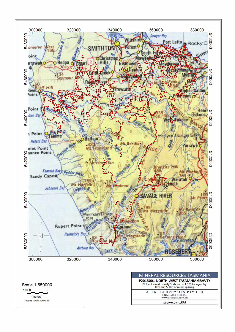
Appendix A contains a station location plot of the acquired gravity stations.

ATLAS GEOPHYSICS PTY LTD Page|3
P2013001

ATLAS GEOPHYSICS PTY LTD Page|4
P2013001
3.0 Personnel
Atlas Geophysics Pty Ltd engages only fit, motivated and safe working professionals to conduct its gravity operations. Acquisition staff members are from a range of backgrounds, usually from the geoscience or geotechnical fields, and all are trained in senior first aid, bush survival, and advanced four wheel driving. Overseeing the acquisition and processing is the company’s team of geophysicists and data processors – a team with a combined total of over 25 years experience in the acquisition, processing and quality analysis of gravity data.
3.1 Project Supervision
Supervising the project from Perth Operations was director Leon Mathews. Leon has been involved in the acquisition, processing and interpretation of potential field data for over 15 years and has directly overseen the acquisition and processing of over 1,000,000 gravity stations.
Leon was responsible for project supervision, as well as for conducting the processing and quality analysis of the gravity data on a daily basis.
All final data processing, QA, reporting and delivery was performed by Leon Mathews.
3.2 Acquisition/Other Personnel
Other personnel participating in field acquisition of the gravity data on this project were:
Crew 01 Sam Giles Project Field Supervisor Crew02 Thomas Ostersen Field Geophysicist Phillip Saul Field Technician

ATLAS GEOPHYSICS PTY LTD Page|5
P2013001
4.0 Equipment and Instrumentation
4.1 Glonass/GPS Receiver Equipment
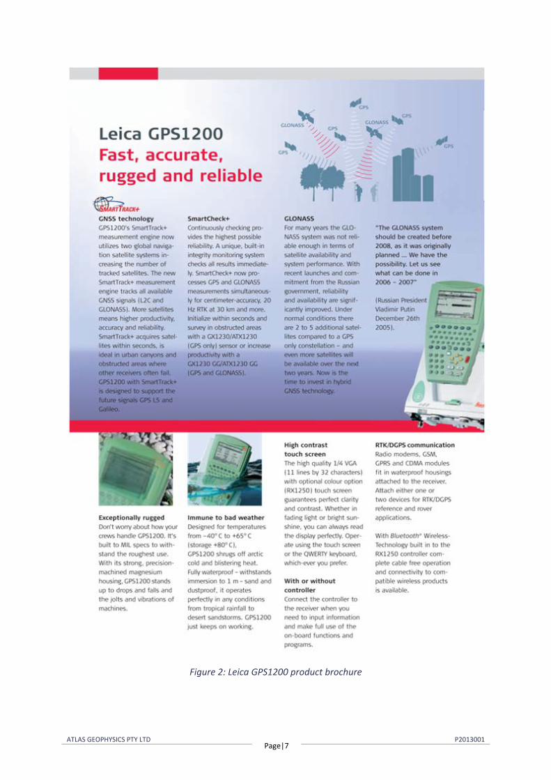
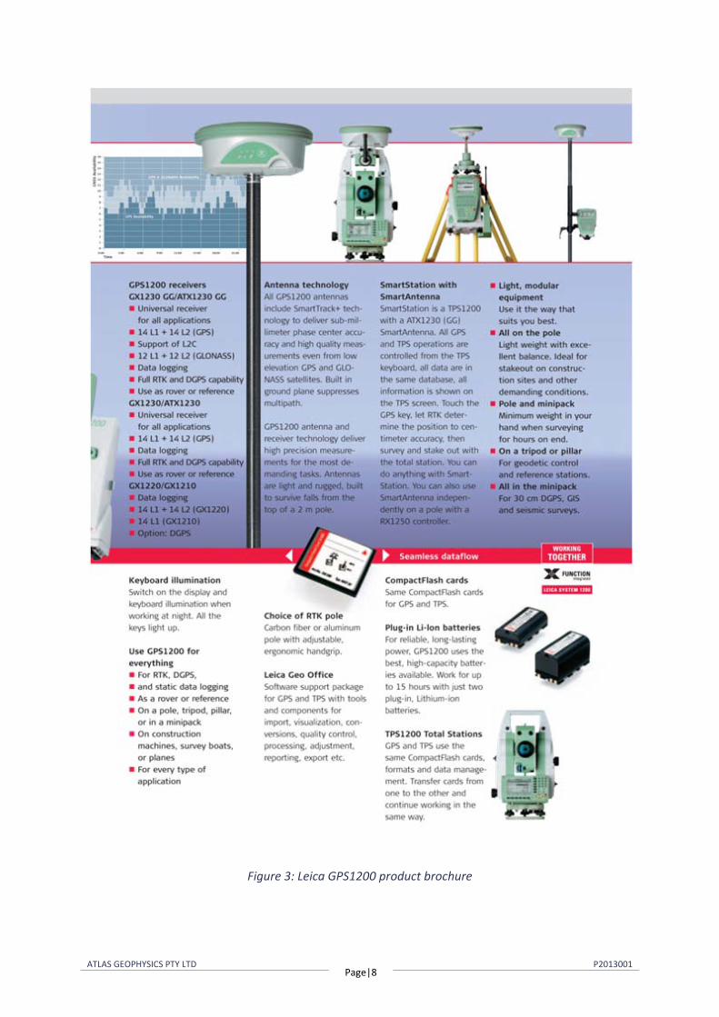
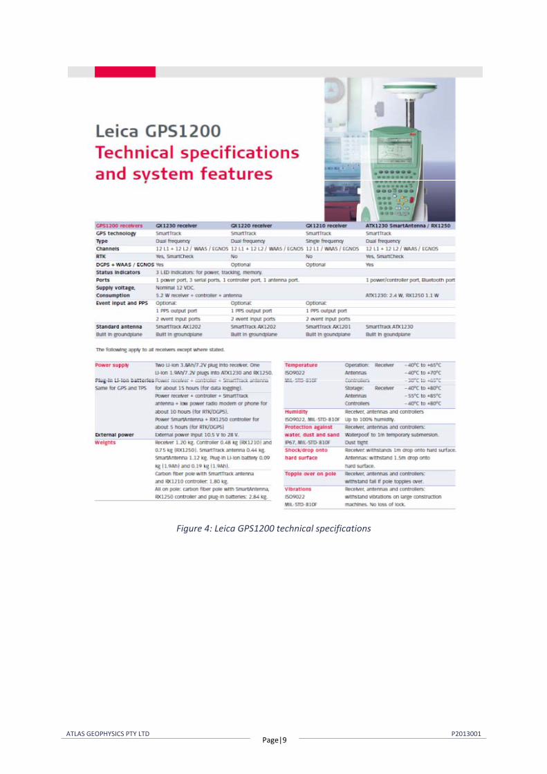
Leading edge dual-frequency GPS technologies from Leica Geosystems such as the GPS1200 have been utilised on the project to allow for post-processed kinematic (PPK) centimetre level accuracy 3D positions. System specifications for the receivers utilised can be found in the attached brochures (Figures 2-4). The GPS1200 system is equipped with future proof GNSS technology which is capable of tracking all available GNSS signals including the currently available GLONASS. These new generation receivers, in conjunction with full GNSS tracking and processing, offer a new level of unmatched solution accuracy and reliability, especially when compared to existing conventional L1, L2 GPS technologies.
The use of Glonass technology in addition to GPS provides very significant advantages:
Increased satellite signal observations
Markedly increased spatial distribution of visible satellites
Reduced Horizontal and Vertical Dilution of Precision (DOP) factors
Improved post-processed-kinematic (PPK) performance
Decreased occupation times means faster acquisition
Eight Leica GPS1200 geodetic grade receivers were utilised to conduct the survey. Two receivers per vehicle were used as post-processed kinematic (PPK) rovers with the other receivers used as base stations for logging static data on multiple control stations.
4.2 Gravity Instrumentation
Complementing the company’s GNSS/GPS technologies is the latest in gravity instrumentation from Scintrex Ltd, the Scintrex CG-5 (Figure 5). The CG-5 digital automated gravity meter offers all of the features of the low noise industry standard CG-3M micro-gravity unit, but is smaller and lighter. It also offers improved noise rejection. By constantly monitoring tilt sensors electronically, the CG-5 automatically compensates for errors in gravity meter tilt. Due to a low mass and the excellent elastic properties of fused quartz, tares are virtually eliminated.
The CG-5 can be transported over very rough terrain, on quad bikes, foot, vehicle or helicopter without taring or drifting. In terms of repeatability, the CG-5 outperforms all existing gravity meter technologies, with a factory quoted repeatability of better than 0.005 mGal.
Table 1 overleaf lists the gravity meters used on the project.

ATLAS GEOPHYSICS PTY LTD Page|6
P2013001
Gravity Meter Type Gravity Meter Code Gravity Meter Serial Number Scintrex CG5 A8 40826 Scintrex CG5 A5 40361
Table 1: Gravity meters used on the project
4.3 Other Equipment
The company utilised the following additional equipment to fully support the operations:
Two HP Laptop computers for data download and processing
Two Iridium satellite phones for long distance communications and scheduled calls
Personal Protective Equipment for all personnel
Batteries and battery chargers
Survey consumables
Tools, engineering and maintenance equipment for vehicle servicing
First aid and survival kits
Tyres and recovery equipment
Two satellite tracking and communication devices.
ATLAS GEOPHYSICS PTY LTD Page|7
P2013001
Figure 2: Leica GPS1200 product brochure
ATLAS GEOPHYSICS PTY LTD Page|8
P2013001
Figure 3: Leica GPS1200 product brochure
ATLAS GEOPHYSICS PTY LTD Page|9
P2013001
Figure 4: Leica GPS1200 technical specifications

ATLAS GEOPHYSICS PTY LTD Page|10
P2013001
Figure 5: Scintrex CG-5 specifications
ATLAS GEOPHYSICS PTY LTD Page|11
P2013001
5.0 Vehicles
Two rental four wheel drive vehicles were used to conduct the survey.
The field crew carried out daily pre-start checks on all vehicles and these have been documented in Atlas Geophysics pre-start log books.

ATLAS GEOPHYSICS PTY LTD Page|12
P2013001
6.0 Accommodation
The crew were accommodated and messed at Grace’s Cottage in Smithton and Bischoff Hotel in Waratah.

ATLAS GEOPHYSICS PTY LTD Page|13
P2013001
7.0 Communications, Internet and Scheduled Calls
The primary method of communication for the field crews was via mobile phones and Iridium satellite phones. The crew sent scheduled check-ins to the WA operations base three times daily.
Internet connections for client contact and data server access were established using a Telstra Turbo Gateway NextG internet modem.

ATLAS GEOPHYSICS PTY LTD Page|14
P2013001
8.0 Survey Methodology
All gravity data were acquired using Atlas Geophysics Pty Ltd vehicle-borne techniques with the exception of a few traverses that were walked. These techniques, which involve concurrent GPS and gravity acquisition, allow for rapid acquisition of very high quality data.
8.1 Gravity and GPS Control Establishment
The survey was controlled using 16 primary GPS control stations and two primary gravity stations (Table 2). The gravity control stations were ideally located near to each of the logistical bases and the GPS control stations were located to minimise baseline length.
At each primary GPS control station, a metal pin of 15cm length was driven into ground level to mark the location of the station. To minimise impact on the environment, the stations were not witnessed with a plaque, tag or picket.
Gravity control stations were placed on permanent features, and to avoid being unsightly, not marked with a plaque.
Digital photos and accurate GPS coordinates can be used to recover the control stations. The details of all primary gravity control stations have been recorded on Atlas Geophysics Pty Ltd control station summary sheets. The sheets include the geodetic coordinates, observed gravity value, station description and a digital photo of the station. The sheets are contained in Appendix B.

ATLAS GEOPHYSICS PTY LTD Page|4
P2013001
Control Station ID Lat / Long / Ht (GDA94, GRS80)
Observed Gravity (ISOGAL65 mGal)
201300100001 -40 50 36.7145 07 19.9 N/A
980275.022
201300100002 -41 26 41.7680 145 31 42.4760 N/A
980182.659
201300100100 -40 57 49.2327 144 56 17.4534 36.833
N/A
201300100101 -41 4 48.1415 144 59 9.8700 45.239
N/A
201300100103 -40 56 56.6658 145 18 38.5308 60.550
N/A
201300100108 -40 57 53.0581 145 24 6.7449 160.314
N/A
201300100111 -41 5 36.9275 145 13 4.4909 220.578
N/A
201300100116 -41 17 35.7013 145 6 2.4394 286.660
N/A
201300100118 -41 28 14.4142 145 20 30.8213 310.624
N/A
201300100122 -41 42 58.9009 145 4 33.4954 181.720
N/A
201300100204 -41 10 43.3910 144 43 23.5229 85.222
N/A
201300100210 -41 3 36.7708 145 28 26.8263 335.745
N/A
201300100214 -41 31 23.0834 145 12 48.5529 360.407
N/A
201300100216 -41 38 42.6355 145 5 7.1465 63.108
N/A
201300100218 -40 58 23.6925 145 34 2.4389 114.477
N/A
201300100221 -41 10 12.7967 145 18 20.6308 410.260
N/A
201300100222 -41 9 46.8508 145 26 20.5526 181.742
N/A
201300100224 -41 11 9.0620145 26 52.6910 193.898
N/A
Table 2: Gravity and GPS control stations used to control the survey
ATLAS GEOPHYSICS PTY LTD Page|4
P2013001
8.1.1 GPS Control
Primary GPS control was established for all control stations except the gravity control stations (where autonomous GPS was used) and this allowed all position and height information obtained from the gravity survey to be tied to the Geocentric Datum of Australia (GDA94), the Geodetic Reference System 1980 (GRS80) and Australian Height Datum (AHD).
Secondary GPS control was used as a backup to assist verification of field measurements under challenging GPS conditions and to restrict GPS baseline length to less than 20km. In the field, whilst the survey was underway, coordinates for these stations were obtained using static base-line processing to the primary control station over a minimum five hour period.
Upon final processing, coordinates for all primary and secondary control stations were obtained using the 5 second static GPS data logged at each station whilst the gravity survey was underway. The static data for each of the control stations used during processing has been submitted to Geoscience Australia’s AUSPOS processing system to produce first-order geodetic coordinates accurate to better than 10mm for the x, y and z observables.
Initial surveying was conducted using adopted control station coordinates since the AUSPOS system requires approximately two weeks before a Final Ephemeris Solution can be delivered. The adopted coordinates were derived from an autonomous GPS measurement at each primary control station giving an accuracy of better than 1m for x, y coordinates and better than 15m for the z coordinate. Once the final ephemeris solution for the control station coordinates was delivered by AUSPOS, all control and field GPS measurements had the necessary DC shift applied to give accurate, absolute positions for east, north and elevation. A listing of final coordinates for all control stations is contained in Appendix C.
8.1.2 Gravity Control
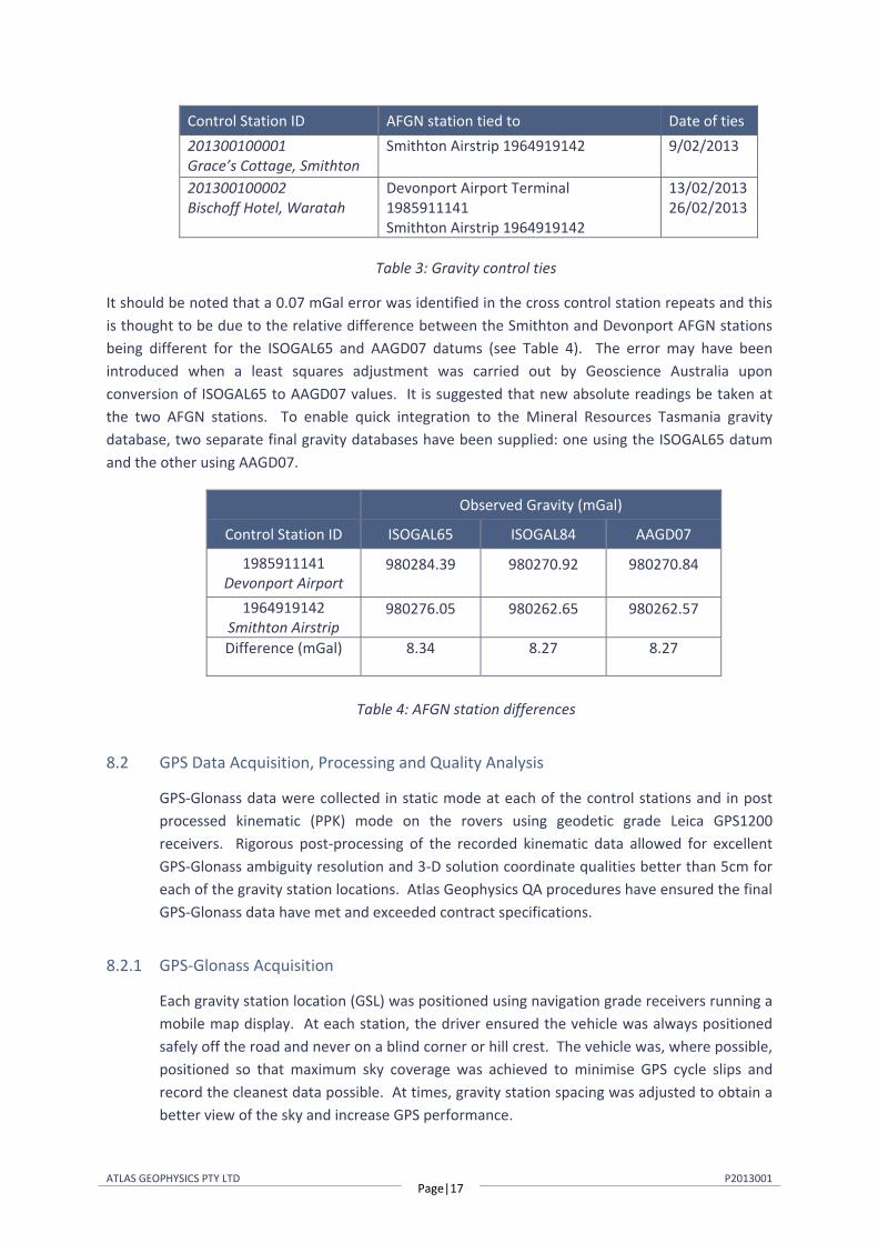
Primary gravity control stations were established at the logistical bases of Smithton and Waratah. Once tied to the Australian Fundamental Gravity Network (AFGN), the gravity control stations allowed all field gravity observations to be tied to both the ISOGAL65 and Australian Absolute Gravity Datum 2007 (AAGD07) datums.
An accurate observed or absolute gravity value for the control stations was established via “ABABA” ties with the project gravity meters to a nearby AFGN station. Table 3 summarises the control ties conducted and Appendix D contains the control tie data. Expected accuracy of the tie surveys would be better than 0.01 mGal (or 0.1 µm/s2).
ATLAS GEOPHYSICS PTY LTD Page|17
P2013001
Control Station ID AFGN station tied to Date of ties 201300100001 Grace’s Cottage, Smithton
Smithton Airstrip 1964919142 9/02/2013
201300100002 Bischoff Hotel, Waratah
Devonport Airport Terminal 1985911141 Smithton Airstrip 1964919142
13/02/201326/02/2013
Table 3: Gravity control ties
It should be noted that a 0.07 mGal error was identified in the cross control station repeats and this is thought to be due to the relative difference between the Smithton and Devonport AFGN stations being different for the ISOGAL65 and AAGD07 datums (see Table 4). The error may have been introduced when a least squares adjustment was carried out by Geoscience Australia upon conversion of ISOGAL65 to AAGD07 values. It is suggested that new absolute readings be taken at the two AFGN stations. To enable quick integration to the Mineral Resources Tasmania gravity database, two separate final gravity databases have been supplied: one using the ISOGAL65 datum and the other using AAGD07.
Observed Gravity (mGal)
Control Station ID ISOGAL65 ISOGAL84 AAGD07
1985911141 Devonport Airport
980284.39 980270.92 980270.84
1964919142 Smithton Airstrip
980276.05 980262.65 980262.57
Difference (mGal) 8.34 8.27 8.27
Table 4: AFGN station differences
8.2 GPS Data Acquisition, Processing and Quality Analysis
GPS-Glonass data were collected in static mode at each of the control stations and in post processed kinematic (PPK) mode on the rovers using geodetic grade Leica GPS1200 receivers. Rigorous post-processing of the recorded kinematic data allowed for excellent GPS-Glonass ambiguity resolution and 3-D solution coordinate qualities better than 5cm for each of the gravity station locations. Atlas Geophysics QA procedures have ensured the final GPS-Glonass data have met and exceeded contract specifications.
8.2.1 GPS-Glonass Acquisition
Each gravity station location (GSL) was positioned using navigation grade receivers running a mobile map display. At each station, the driver ensured the vehicle was always positioned safely off the road and never on a blind corner or hill crest. The vehicle was, where possible, positioned so that maximum sky coverage was achieved to minimise GPS cycle slips and record the cleanest data possible. At times, gravity station spacing was adjusted to obtain a better view of the sky and increase GPS performance.

ATLAS GEOPHYSICS PTY LTD Page|18
P2013001
For the kinematic vehicle operations, two separate GPS-Glonass receivers were used to allow for solution comparison when GPS conditions were challenging. Both receivers were carried in the cab of the vehicle, with one sensor mounted on a tall, fixed length aluminium pole secured to the rear tray and the other on the roof of the vehicle using a magnetic mount. When operating on foot, a single receiver was carried in a backpack with the sensor sitting atop a fixed length aluminium pole (2m).
Phase data were logged at five second epochs onto Compact Flashcards (CF) for later downloading and post-processing. Occupation times were commensurate with the time of day, number of satellites visible, Dilution of Precision (DOP) and GPS baseline length. Generally, a minimum 10 minute window was used, but some stations required in excess of 30 minutes because of poor satellite visibility and/or cycle slips.
Static data were also concurrently logged at the primary and secondary GPS control stations to allow for later kinematic processing. Where possible, static control stations were positioned in open areas such as farmland or cleared areas for maximum GPS satellite coverage.
8.2.2 GPS-Glonass Processing
The acquired raw GPS-Glonass data were processed nightly using Novatel Waypoint Grafnav v8.40 post-processing software (Figure 6). GrafNav is a fully-featured kinematic and static GPS/Glonass post-processing package that uses Waypoint’s robust GPS/Glonass processing carrier phase kinematic (CPK) filter engine. The software is capable of processing raw kinematic GPS/Glonass data from most GPS/GNSS receivers and allows the user to process the roving data from as many as eight separate control stations to achieve accuracies at the centimetre level. The software can automatically switch from static to kinematic processing and has a fixed static solution for static initialisation of short or medium baselines that are below 30km. Kinematic Ambiguity Resolution (KAR) allows the session to start in kinematic mode and can help fix otherwise unrecoverable cycle slips. Ionospheric processing and modelling is also included with the software and can help improve accuracy, especially over long baselines. Advantages of the Waypoint processing engine over other packages include:
Fast Processing – The Grafnav engine is one of the fastest on the market. For a single base station, a 2.40 Mhz PIII CPU can expect to process GPS data at 670 epochs/second. This means that a 4-hour 2 Hz data set will process one direction in 22 seconds. For two bases, processing takes 250 epochs/second or about 1 minute for the same 4-hour data set. For 4 bases, these times are 50 epochs/second or about 5 minutes.
Reliable OTF Processing – Waypoint’s on-the-fly KAR algorithm has had years of development and testing. Various implementations and numerous options are available to control this powerful feature.
Multi-Base (MB) processing – With Version 8.40, GrafNav now supports true multiple control station processing where all of the baselines are incorporated into one sophisticated Kalman filter. This can spatially de-correlate some of the error

ATLAS GEOPHYSICS PTY LTD Page|19
P2013001
sources while also allowing integer ambiguity determination using the closest base station. Satellite drop-outs at one base will also be compensated by the others. The two biggest advantages are improved overall accuracies and much less operator effort required to process and QC such data.
Accurate Static Processing – Three modes of static processing are implemented in the main processing kernel.
Dual Frequency Support – Full dual frequency GPS processing comes with the software. For ambiguity resolution, this entails wide/narrow lane solutions for KAR, fixed static and quick static. The GrafNav kernel implements two ionospheric processing modes including the iono-free and relative models.
Forward and Reverse – Processing can be performed in both the forward and reverse directions. GrafNav also has the ability to combine these two solutions to obtain a globally optimum one.
GPS + GLONASS – The GrafNav kernel has the ability to also process GPS+GLONASS data. This is especially advantageous for applications in forested areas, where the additional satellite coverage can improve accuracies.
Velocity Determination – Since the GrafNav kernel includes the L1 doppler measurement in its Kalman filter, velocity determination is very accurate. In addition to this, a considerable amount of code has been added specifically for the detection and removal of Doppler errors.
High Dynamics – The GrafNav kernel can handle extremely high dynamics from missiles, rockets, dropped ordinances, and fast flying aircraft.
Long Baseline - Because precise ephemeris and dual frequency processing is supported, long baselines accuracies can be as good as 0.1 PPM.

ATLAS GEOPHYSICS PTY LTD Page|20
P2013001
Figure 6: Waypoint Grafnav Processing Software
Once each station was processed to give a solution for the WGS84 position and elevation at ground level (i.e. corrected for sensor height), conversion between GPS-Glonass derived WGS84/GDA94 coordinates to Map Grid of Australia (MGA) coordinates was conducted within Waypoint. For most practical applications, where a horizontal accuracy of only a metre or greater is required, GDA94 coordinates can be considered the same as WGS84. MGA94 coordinates were obtained by projecting the GPS-derived WGS84 coordinates using a Universal Transverse Mercator (UTM) projection with zone 55S. For legacy purposes, AMG66 coordinates were calculated from the MGA94 coordinates using program GDA. For more information about WGS84, GDA94, MGA94 and AMG66 coordinates, the reader is asked to visit the Geoscience Australia website http://www.ga.gov.au/geodesy/datums/gda.jsp.
Elevations above the Australian Height Datum (AHD) were modelled using Waypoint 8.40 software and the latest geoid model for Australia, AUSGEOID09. Information about the geoid and the modelling process used to extract separations (N values) can be found at http://www.ga.gov.au/geodesy/ausgeoid/. To obtain AHD elevation, the modelled N value is subtracted from the GPS derived WGS84/GRS80 ellipsoidal height (Figure 7).

ATLAS GEOPHYSICS PTY LTD Page|21
P2013001
Figure 7: Geoid-Ellipsoid Separation
8.2.3 GPS/Glonass Quality Analysis
Due to the difficult GPS conditions endured for most of the project, rigorous quality analysis procedures were required to ensure the accuracy of the GPS solution. This was done using Waypoint Grafnav’s built in QA tools. Some of the Waypoint tools used on this project include:
Combined Separation Plot: This plot shows the difference between the forward and reverse solutions (Figure 8). A perfect solution would have a separation of zero as this indicated the carrier phase ambiguities have been determined to be exactly the same value in both directions. A separation of better than 0.1m on a survey would indicate that the data is of high quality.
Figure 8: Combined Separation Plot
Float or Fixed Ambiguity Status Plot: This plot shows if the final solution is float or fixed (Figure 9). Fixed integer ambiguities generally have better accuracies (usually < 10cm accuracy). Ideally the plot should show fixed as this indicated an integer ambiguity fix on both forward and reverse directions. No Float solutions were used on this project – all solutions were fixed.

ATLAS GEOPHYSICS PTY LTD Page|22
P2013001
Figure 9: Float or Fixed Ambiguity Status Plot
Quality Factor Plot: This plot shows the quality of the final solution (Figure 10). There are five different quality factors plotted and these factors are also output in the Atlas Geophysics Pty Ltd GPS data file.
Quality 1 – Fixed Integer (Green) Quality 2 – Stable Float (Aqua) Quality 3 – Converging Float (Blue) Quality 4 – DGPS or worse (Red) Quality 5 – Single Point (Yellow)
Increasing quality factors indicate a worse solution. This is not a perfect indication, but it can be useful to isolate problems.
Figure 10: Quality factor plot
Complementing Waypoint GrafNav QA tools is the company’s own in-house GPS quality analysis software. A module built into AGRIS (Atlas Geophysics Reduction and Information Software) allows the user to import the Waypoint output files and examine quality factors such as station repeatability between multiple control stations, coordinate velocity, dilution of precision, coordinate quality factor and standard error for each gravity station location. If
ATLAS GEOPHYSICS PTY LTD Page|23
P2013001
a particular station failed to meet QA specifications, then it was reprocessed using all permutations of possible base/rover baseline combinations until it did. If QA specifications were not met after this process was exhausted, then the station was repeated at no cost to the client.
The procedure is carried out before merging the positional data with gravity data for final reduction to Bouguer Anomaly. Comprehensive statistics, repeatability analysis and histogram plotting are also performed.
8.3 Gravity Data Acquisition, Processing and Quality Analysis
Gravity data were gained using the company’s high accuracy vehicle-borne techniques. The company’s own in-house reduction and QA software was used to reduce the data on a daily basis to ensure quality and integrity. Final delivered data met and exceeded contract specifications.
8.3.1 Calibration of the Gravity Meters
The gravity meters used for survey have been recently calibrated on the Guildford Cemetery – Helena Valley Primary School calibration range (2010990117- 2010990217) in Western Australia. The calibration process has validated each gravity meter’s scale factor to ensure reduction of the survey data produces correct Observed Gravities from measured dial reading values.
Weekly tilt-tests and cycles were conducted to ensure the meters drift and tilt correction factors were valid. Gravity meter drift rates were monitored on a day to day basis using AGRIS software.
8.3.2 Acquisition of the Gravity Data
Gravity data were acquired concurrently with GPS-Glonass data using Scintrex CG5 gravity meters. Data were acquired in a single loop controlled by observations at the gravity control stations. Each loop contained a minimum of one repeated readings so that an interlocking network of closed loops was formed. A total of 5.58% repeats were acquired for quality control purposes.
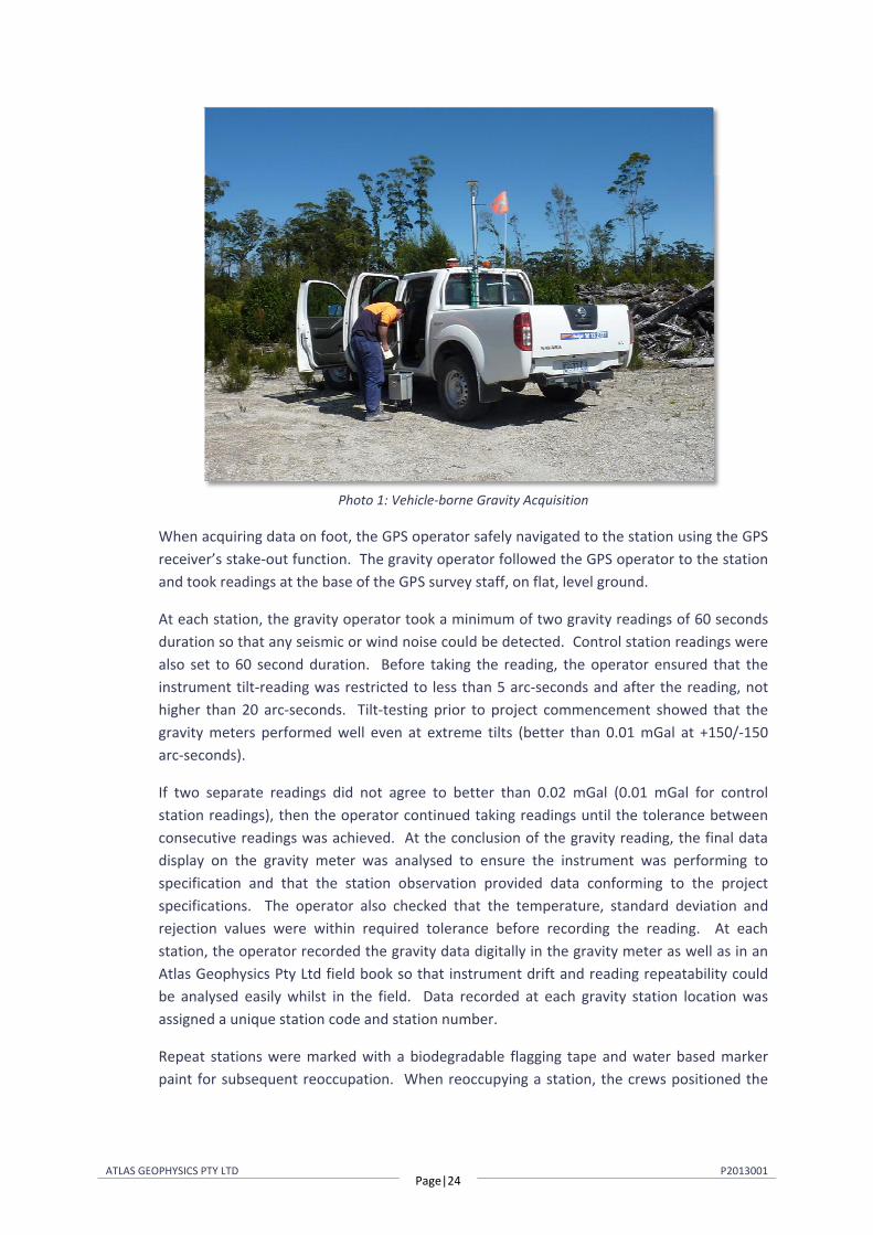
When acquiring gravity data using a vehicle, the driver, after safely navigating to the station, parked the vehicle alongside the road in a safe position, with headlights on, rotating beacon flashing, park brake applied and vehicle engine off. Once safe to do so, the observer disembarked the vehicle on the verge or shoulder side and took the gravity reading alongside the vehicle, underneath the GPS observation point (Photo 1). At all times, the vehicle was parked on flat, level ground. Under no circumstances, did the observer acquire a reading in front of, or behind the vehicle.
ATLAS GEOPHYSICS PTY LTD Page|24
P2013001
Photo 1: Vehicle-borne Gravity Acquisition
When acquiring data on foot, the GPS operator safely navigated to the station using the GPS receiver’s stake-out function. The gravity operator followed the GPS operator to the station and took readings at the base of the GPS survey staff, on flat, level ground.
At each station, the gravity operator took a minimum of two gravity readings of 60 seconds duration so that any seismic or wind noise could be detected. Control station readings were also set to 60 second duration. Before taking the reading, the operator ensured that the instrument tilt-reading was restricted to less than 5 arc-seconds and after the reading, not higher than 20 arc-seconds. Tilt-testing prior to project commencement showed that the gravity meters performed well even at extreme tilts (better than 0.01 mGal at +150/-150 arc-seconds).
If two separate readings did not agree to better than 0.02 mGal (0.01 mGal for control station readings), then the operator continued taking readings until the tolerance between consecutive readings was achieved. At the conclusion of the gravity reading, the final data display on the gravity meter was analysed to ensure the instrument was performing to specification and that the station observation provided data conforming to the project specifications. The operator also checked that the temperature, standard deviation and rejection values were within required tolerance before recording the reading. At each station, the operator recorded the gravity data digitally in the gravity meter as well as in an Atlas Geophysics Pty Ltd field book so that instrument drift and reading repeatability could be analysed easily whilst in the field. Data recorded at each gravity station location was assigned a unique station code and station number.
Repeat stations were marked with a biodegradable flagging tape and water based marker paint for subsequent reoccupation. When reoccupying a station, the crews positioned the
ATLAS GEOPHYSICS PTY LTD Page|25
P2013001
vehicle/walking staff as close to the original position as possible (usually better than 0.5m). All repeat gravity observations were taken in exactly the same location.
8.3.3 Processing of the Gravity Data
The acquired gravity data were processed using the company’s in-house gravity pre-processing and reduction software, AGRIS. This software allows for full data pre-processing, reduction to Bouguer Anomaly, repeatability and statistical analysis, as well as full quality analysis of the output dataset.
The software is capable of downloading Scintrex CG3/CG5 and Lacoste Romberg gravity data. Once downloaded, the gravity data is analysed for consistency and preliminary QA is performed on the data to check that observations meet specification for standard deviation, reading rejection, temperature and tilt values. Once the data is verified, the software averages the multiple readings and performs a merge with the GPS data (which it has also previously verified) and performs a linear drift correction and earth tide correction. Calculation of Free Air and Bouguer Anomalies is then performed using the contract specified formulae.
The following corrections were applied to the dataset to produce Bouguer Anomaly values for each of the gravity stations. All formulae produce values in µm/s2. To convert to mGal units, divide by 10.
Instrument scale factor: This correction is used to correct a gravity reading (in dial units) to a relative gravity unit value based on the meter calibration. = 10 ∙ ( ∙ ( )) where,
corrected reading in gravity units gravity meter reading in dial units ( ) scale factor (dial units/milliGal)
Earth Tide Correction: The earth is subject to variations in gravity due to the gravitational attraction of the Sun and the Moon. These background variations can be corrected for using a predictive formula which utilises the gravity observation position and time of observation. The Scintrex CG5 gravity meter automatically calculates ETC but uses only an approximate position for the gravity observation so is not entirely accurate. For this reason, the Scintrex ETC is subtracted from the reading and a new correction calculated within AGRIS software. = +
where, tide corrected reading in gravity units scale factor corrected reading in gravity units
Earth Tide Correction (ETC) in gravity units
ATLAS GEOPHYSICS PTY LTD Page|26
P2013001
Instrument Drift Correction: Since all gravity meters are mechanical they are all prone to instrument drift. Drift can be caused by mechanical stresses and strains in the spring mechanism as the meter is moved, knocked, reset, subjected to temperature extremes, subjected to vibration, unclamped etc. The most common cause of instrument drift is due to extension of the sensor spring with changes in temperature (obeying Hooke’s law). To calculate and correct for daily instrument drift, the difference between the gravity control station readings (closure error) is used to assume the drift and a linear correction is applied.
= −−
where, Instrument Drift in gu/hour control station 2nd reading in gravity units control station 1st reading in gravity units control station 2 time control station 1 time
Observed Gravity: The preceding corrections are applied to the raw gravity reading to calculate the earth’s absolute gravitational attraction at each gravity station. The corrections produced Observed Gravities on the AAGD07, ISOGAL84 and ISOGAL65 gravity datums. = + ( − ) − ( − ) ∙
where, Observed Gravity in gravity units
control station 1 known Observed Gravity in gravity units tide corrected reading in gravity units
control station 1 reading in gravity units reading time
control station 1 time instrument drift in gravity units/hour
Theoretical Gravity 1980: The theoretical (or normal) gravity value at each gravity station is calculated based on the assumption that the Earth is a homogeneous ellipsoid. The closed form of the 1980 International Gravity Formula is used to approximate the theoretical gravity at each station location and essentially produce a latitude correction. Gravity values vary with latitude as the earth is not a perfect sphere and the polar radius is much smaller than the equatorial radius. The effect of centrifugal acceleration is also different at the poles versus the equator. = 9780326.7715((1 + 0.001931851353( )/( (1 − 0.0066943800229( ))) where,
Theoretical Gravity 1980 in gravity units GDA94 latitude at the gravity station in decimal degrees
ATLAS GEOPHYSICS PTY LTD Page|27
P2013001
Theoretical Gravity 1967: The theoretical (or normal) gravity value at each gravity station is calculated based on the assumption that the Earth is a homogeneous ellipsoid. The 1967 variant of the International Gravity Formula is used to approximate the theoretical gravity at each station location and essentially produce a latitude correction. Gravity values vary with latitude as the earth is not a perfect sphere and the polar radius is much smaller than the equatorial radius. The effect of centrifugal acceleration is also different at the poles versus the equator. = (9780318.456 ∙ 1 + 0.005278895 ∙ ( ) + 0.000023462 ∙ ( ) ) where,
Theoretical Gravity 1967 in gravity units GDA94 latitude at the gravity station in decimal degrees
Atmospheric Correction: The gravity effect of the atmosphere above the ellipsoid can be calculated with an atmospheric model and is subtracted from the theoretical gravity. = 8.74– 0.00099 ∙ ℎ + 0.0000000356 ∙ ℎ
where, Atmospheric Correction in gravity units ℎ elevation above the GRS80 ellipsoid in metres
Ellipsoidal Free Air Correction: Since the gravity field varies inversely with the square of distance, it is necessary to correct for elevation changes from the reference ellipsoid (GRS80). Gravitational attraction decreases as the elevation above the reference ellipsoid increases. = −(3.087691– 0.004398 ² ) ∙ ℎ + 7.2125 ∙ 10 ∙ ℎ
where, Ellipsoidal Free Air Correction in gravity units
GDA94 latitude at the gravity station in decimal degrees ℎ elevation above the GRS80 ellipsoid in metres
Geoidal Free Air Correction: Since the gravity field varies inversely with the square of distance, it is necessary to correct for elevation changes from the reference geoid (AHD). Gravitational attraction decreases as the elevation above the reference geoid increases. = 3.08768 − 0.00440 ( ) ∙ ℎ − 0.000001442 ∙ ℎ
where, Free Air Correction in gravity units
GDA94 latitude at the gravity station in decimal degrees ℎ elevation above the reference geoid (AHD) in metres
Spherical Cap Bouguer Correction: If a gravity observation is made above the reference ellipsoid, the effect of rock material between the observation and the ellipsoid must be taken into account. The mass of rock makes a positive contribution to the gravity value. The

ATLAS GEOPHYSICS PTY LTD Page|28
P2013001
correction is calculated using the closed form equation for the gravity effect of a spherical cap of radius 166.7km, based on a spherical Earth with a mean radius of 6,371.0087714km, height relative the ellipsoid and rock densities of 2.67, 2.40 and 2.20 tm-3 (gm/cc). = 2πGρ((1 + μ) ∙ ℎ– λR) where,
Spherical Cap Bouguer Correction in gravity units gravitational constant = 6.67428∙10-11m3kg-1s-2 ρ rock density (2.67, 2.40 and 2.20 gm/cc) ℎ elevation above the GRS80 ellipsoid in metres R ( + ℎ) the radius of the earth at the station mean radius of the earth = 6,371.0087714 km (on the GRS80 ellipsoid) & are dimensionless coefficients defined by: = ((1/3) ∙ η − η)
where, η ℎ/
= (1/3){( + + )[( – ) + ] + + ∙ ( /( – + [( – ) + ] )} where,
3 ∙ 2 − 2 −6 ∙ 2 ∙ sin( /2) + 4 ∙ 3( /2) δ ( / ) −3 ∙ ∙
2 ∙ [ ( /2) − ( /2)] / with S = Bullard B Surface radius = 166.735 km
Geoidal Bouguer Correction: If a gravity observation is made above the reference geoid, the effect of rock material between the observation and the ellipsoid must be taken into account. The mass of rock makes a positive contribution to the gravity value. The slab of rock makes a positive contribution to the gravity value. Rock densities of 2.67, 2.40 and 2.20 (gm/cc) were used in the correction. = 0.4191 ∙ ρ ∙ ℎ
where, Geoidal Bouguer Correction in gravity units ρ rock density (2.67, 2.40 and 2.20 gm/cc) ℎ elevation above the reference geoid (AHD) in m
Terrain Correction: The terrain correction accounts for variations in gravity values caused by variations in topography near the observation point. The correction accounts for the attraction of material above the assumed Bouguer slab and for the over-correction made by the Bouguer correction when in valleys. The terrain correction is positive regardless of

ATLAS GEOPHYSICS PTY LTD Page|29
P2013001
whether the local topography consists of a mountain or a valley. Terrain corrections were not applied on this project as they are expected to be carried out by the client.
Ellipsoidal Free Air Anomaly: The Ellipsoidal Free Air Anomaly is the difference between the observed gravity and theoretical gravity that has been computed for latitude and corrected for the elevation of the gravity station above or below the reference ellipsoid.
= – ( − ) −
where, Ellipsoidal Free Air Anomaly in gravity units Observed Gravity in gravity units
Theoretical Gravity 1980 in gravity units Atmospheric Correction in gravity units
Ellipsoidal Free Air Correction in gravity units
Geoidal Free Air Anomaly: The Geoidal Free Air Anomaly is the difference between the observed gravity and theoretical gravity that has been computed for latitude and corrected for the elevation of the gravity station above or below the reference geoid.
= − +
where, Free Air Anomaly in gravity units Observed Gravity on the ISOGAL84 datum in gravity units Theoretical Gravity 1967 in gravity units Geoidal Free Air Correction in gravity units
Spherical Cap Bouguer Anomaly: The Spherical Cap Bouguer Anomaly is computed from the Ellipsoidal Free Air Anomaly above by removing the attraction of the spherical cap calculated by the Spherical Cap Bouguer Correction.
= −
where, Spherical Cap Bouguer Anomaly in gravity units Ellipsoidal Free Air Anomaly in gravity units Bouguer Correction in gravity units
Geoidal Bouguer Anomaly: The Geoidal Bouguer Anomaly is computed from the Geoidal Free Air Anomaly above by removing the attraction of the slab calculated by the Geoidal Bouguer Correction.
= −
where, Geoidal Bouguer Anomaly in gravity units
Geoidal Free Air Anomaly in gravity units Geoidal Bouguer Correction in gravity units

ATLAS GEOPHYSICS PTY LTD Page|30
P2013001
Complete Bouguer Anomaly: This is obtained by adding the terrain correction to the Bouguer Anomaly (Spherical Cap or Geoidal). The Complete Bouguer Anomaly is the most interpretable value derived from a gravity survey as changes in the anomaly can be directly attributed to lateral density contrasts within the geology below the observation point.
= +
where, Complete Bouguer Anomaly in gravity units
Bouguer Anomaly in gravity units TC Terrain Correction in gravity units
8.3.4 Quality Analysis of the Processed Gravity data
Following reduction of the data to Bouguer Anomaly, repeatability and QA procedures were applied to both the positional and gravity observations using AGRIS software. AGRIS checks the following as part of its QA processing:
Easting Observation Repeatability and Histogram
Northing Observation Repeatability and Histogram
Elevation Observation Repeatability and Histogram
Gravity Observation Repeatability and Histogram
Gravity SD, Tilt XY, Temperature, Rejection, Reading Variance
Gravity meter drift / closure
Gravity meter loop time, drift per hour
GPS Dilution of Precision, Coordinate Quality Factor, Standard Error
Variation of surveyed station location from programmed location
QA procedures were applied to the gravity data on a daily basis and any gravity stations not conforming to contract specifications were repeated by the company at no cost to the client.

ATLAS GEOPHYSICS PTY LTD Page|31
P2013001
8.3.5 Additional Processing, Gridding and Plotting
Complementing the QA procedures is additional daily gridding, imaging and plotting of the elevation and gravity data. Once processed to Bouguer Anomaly and assessed for QA, data are imported into Geosoft Oasis Montaj or ChrisDBF software for gridding at 1/4th the station spacing to produce ERMapper compatible grid files. Resultant grids are contoured, filtered and interpreted using ERMapper and ArcMap software to check that data is smoothly varying and that no spurious anomalies are present. A first vertical, tilt angle and horizontal derivative filter are routinely applied to the data as these filters allow for excellent noise recognition. Once identified, any spurious stations can be field checked by the crew the following day and repeated if required. During the course of the survey one anomalous station was field checked and found to be valid.
Plotting of the acquired stations on a daily basis allowed for identification of any missed stations which were then gained the following day.
ATLAS GEOPHYSICS PTY LTD Page|32
P2013001
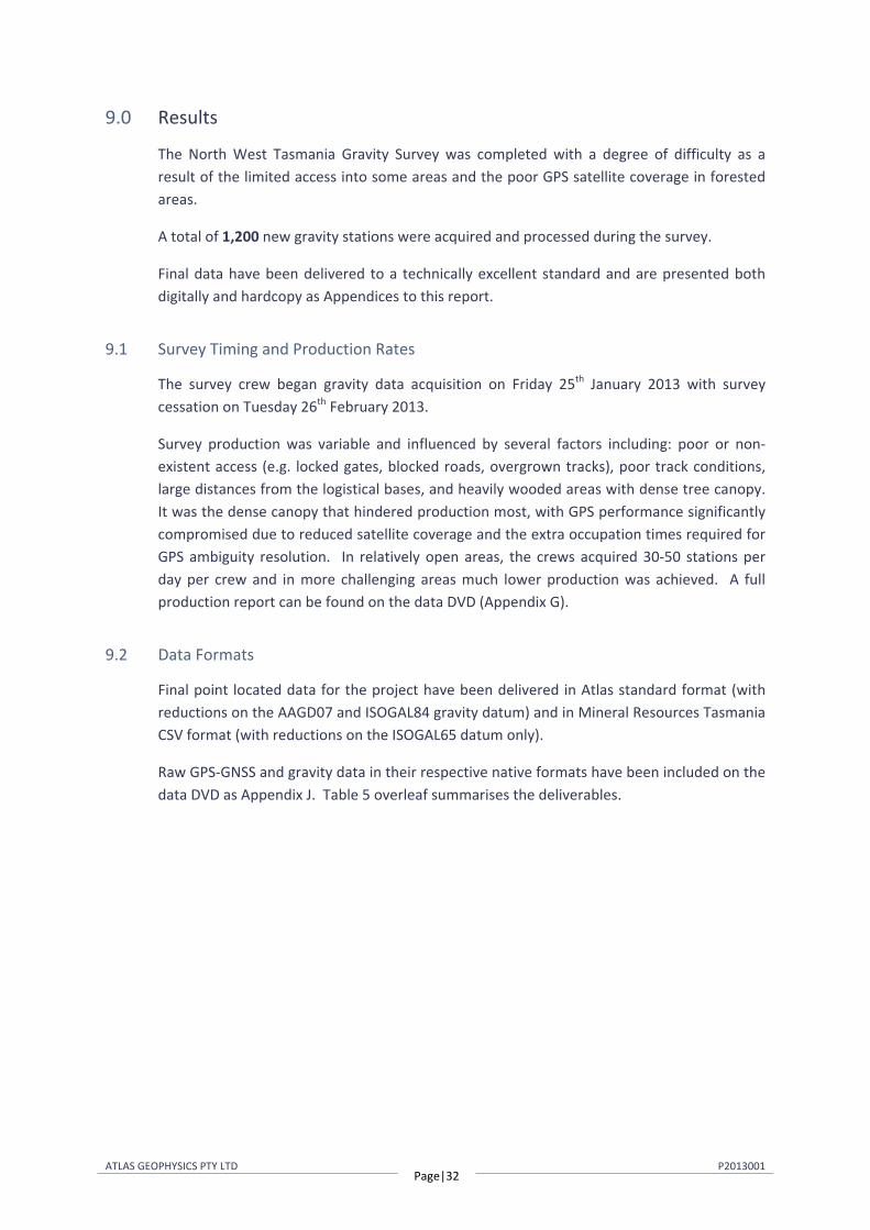
9.0 Results
The North West Tasmania Gravity Survey was completed with a degree of difficulty as a result of the limited access into some areas and the poor GPS satellite coverage in forested areas.
A total of 1,200 new gravity stations were acquired and processed during the survey.
Final data have been delivered to a technically excellent standard and are presented both digitally and hardcopy as Appendices to this report.
9.1 Survey Timing and Production Rates
The survey crew began gravity data acquisition on Friday 25th January 2013 with survey cessation on Tuesday 26th February 2013.
Survey production was variable and influenced by several factors including: poor or non-existent access (e.g. locked gates, blocked roads, overgrown tracks), poor track conditions, large distances from the logistical bases, and heavily wooded areas with dense tree canopy. It was the dense canopy that hindered production most, with GPS performance significantly compromised due to reduced satellite coverage and the extra occupation times required for GPS ambiguity resolution. In relatively open areas, the crews acquired 30-50 stations per day per crew and in more challenging areas much lower production was achieved. A full production report can be found on the data DVD (Appendix G).
9.2 Data Formats
Final point located data for the project have been delivered in Atlas standard format (with reductions on the AAGD07 and ISOGAL84 gravity datum) and in Mineral Resources Tasmania CSV format (with reductions on the ISOGAL65 datum only).
Raw GPS-GNSS and gravity data in their respective native formats have been included on the data DVD as Appendix J. Table 5 overleaf summarises the deliverables.
ATLAS GEOPHYSICS PTY LTD Page|33
P2013001
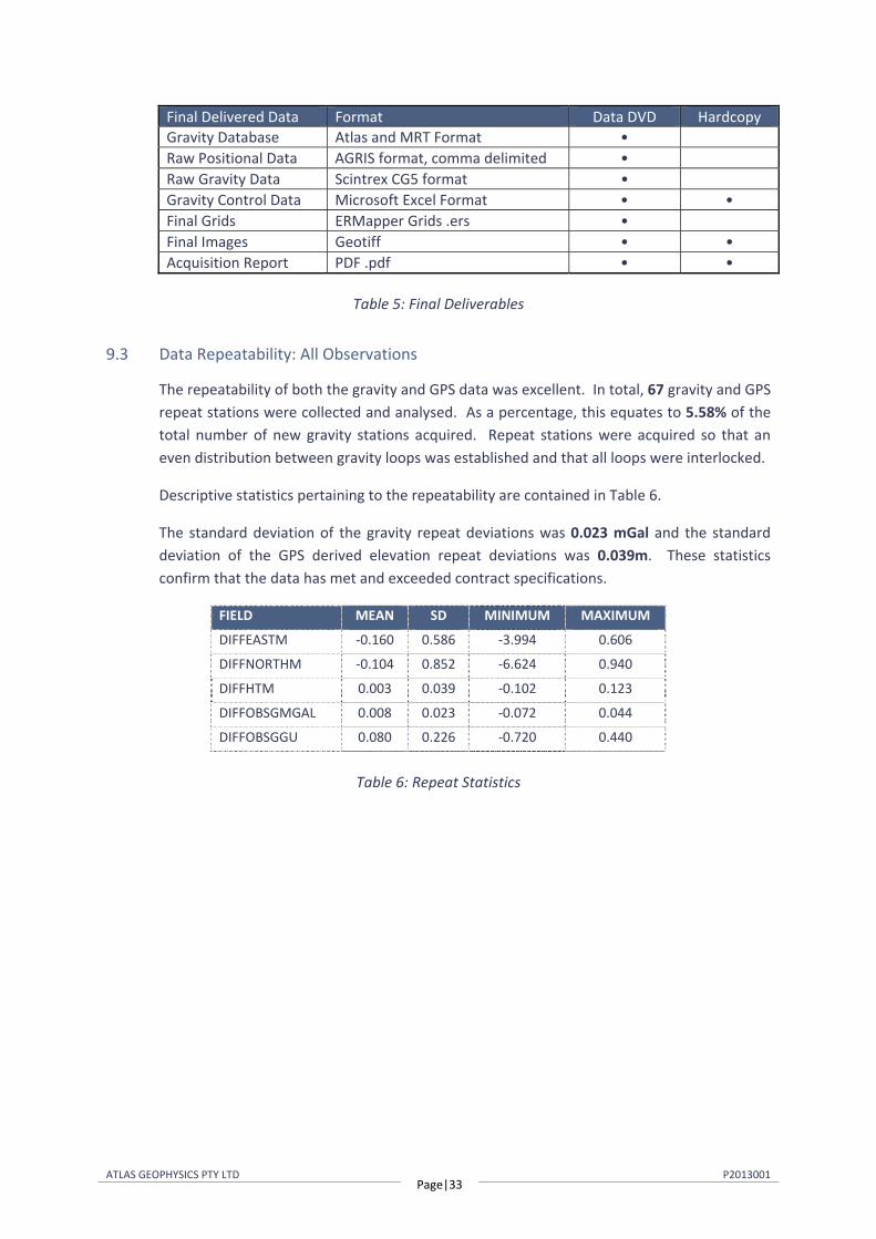
Final Delivered Data Format Data DVD HardcopyGravity Database Atlas and MRT Format • Raw Positional Data AGRIS format, comma delimited • Raw Gravity Data Scintrex CG5 format • Gravity Control Data Microsoft Excel Format • • Final Grids ERMapper Grids .ers • Final Images Geotiff • • Acquisition Report PDF .pdf • •
Table 5: Final Deliverables
9.3 Data Repeatability: All Observations
The repeatability of both the gravity and GPS data was excellent. In total, 67 gravity and GPS repeat stations were collected and analysed. As a percentage, this equates to 5.58% of the total number of new gravity stations acquired. Repeat stations were acquired so that an even distribution between gravity loops was established and that all loops were interlocked.
Descriptive statistics pertaining to the repeatability are contained in Table 6.
The standard deviation of the gravity repeat deviations was 0.023 mGal and the standard deviation of the GPS derived elevation repeat deviations was 0.039m. These statistics confirm that the data has met and exceeded contract specifications.
FIELD MEAN SD MINIMUM MAXIMUM
DIFFEASTM -0.160 0.586 -3.994 0.606
DIFFNORTHM -0.104 0.852 -6.624 0.940
DIFFHTM 0.003 0.039 -0.102 0.123
DIFFOBSGMGAL 0.008 0.023 -0.072 0.044
DIFFOBSGGU 0.080 0.226 -0.720 0.440
Table 6: Repeat Statistics
ATLAS GEOPHYSICS PTY LTD Page|34
P2013001
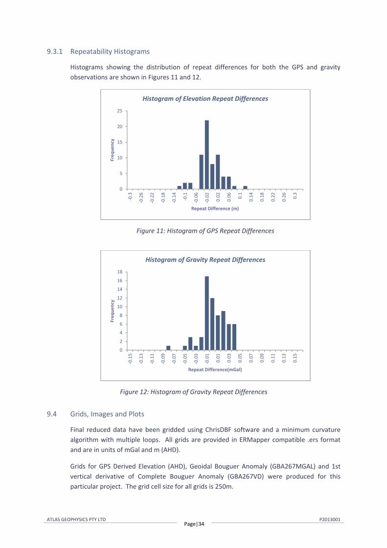
9.3.1 Repeatability Histograms
Histograms showing the distribution of repeat differences for both the GPS and gravity observations are shown in Figures 11 and 12.
Figure 11: Histogram of GPS Repeat Differences
Figure 12: Histogram of Gravity Repeat Differences
9.4 Grids, Images and Plots
Final reduced data have been gridded using ChrisDBF software and a minimum curvature algorithm with multiple loops. All grids are provided in ERMapper compatible .ers format and are in units of mGal and m (AHD).
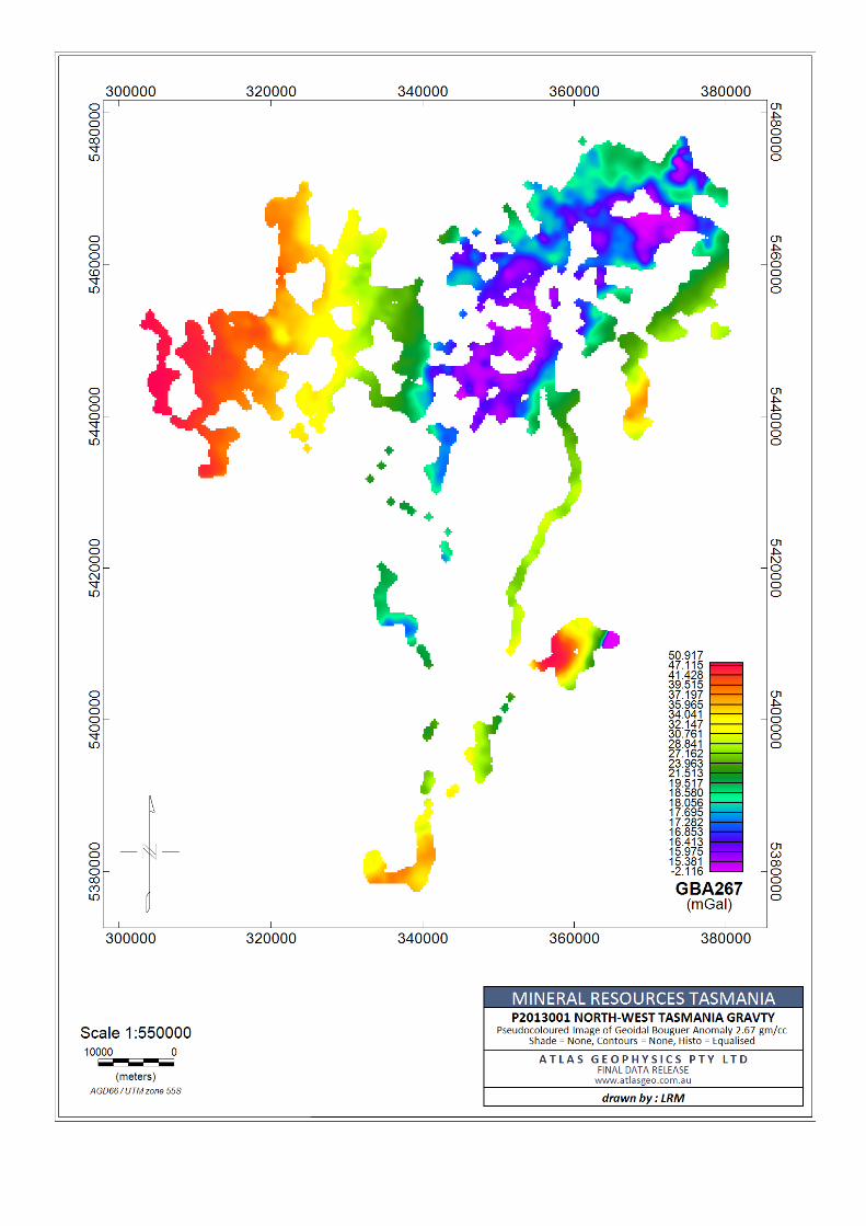
Grids for GPS Derived Elevation (AHD), Geoidal Bouguer Anomaly (GBA267MGAL) and 1st vertical derivative of Complete Bouguer Anomaly (GBA267VD) were produced for this particular project. The grid cell size for all grids is 250m.
0
5
10
15
20
25
-0.3
-0.2
6
-0.2
2
-0.1
8
-0.1
4
-0.1
-0.0
6
-0.0
2
0.02
0.06 0.
1
0.14
0.18
0.22
0.26 0.
3
Freq
uenc
y
Repeat Difference (m)
Histogram of Elevation Repeat Differences
0
2
4
6
8
10
12
14
16
18
-0.1
5
-0.1
3
-0.1
1
-0.0
9
-0.0
7
-0.0
5
-0.0
3
-0.0
1
0.01
0.03
0.05
0.07
0.09
0.11
0.13
0.15
Freq
uenc
y
Repeat Difference(mGal)
Histogram of Gravity Repeat Differences

ATLAS GEOPHYSICS PTY LTD Page|35
P2013001
The grids produced have been imaged using Geosoft Oasis Montaj mapping and processing software. Five plots of these images have been included with this report to assist in data interpretation (Appendix A). The plots have been included digitally on the data DVD in Arcmap GIS compatible TIFF format.
Station Location Plot: The first plot displays the acquired gravity station locations overlayed on a 1:1 million topographic map of the area and surrounds. As evident on the plot, some stations have been moved off the original programmed co-ordinates due to terrain and safety considerations.
GPS Derived Elevation: This plot displays a pseudocoloured grid of the digital elevation data obtained from the gravity survey (AHD). A histogram equalisation colour stretch has been applied when pseudocolouring.
Geoidal Bouguer Anomaly 2.67 Contours: This plot displays a pseudocoloured grid of Geoidal Bouguer Anomaly calculated with a rock density of 2.67 gm/cc. A histogram equalisation stretch has been applied when pseudocolouring.
Vertical Derivative Image: This plot displays a pseudocoloured grid of the first vertical derivative of Geodial Bouguer Anomaly calculated with a rock density of gm/cc.

ATLAS GEOPHYSICS PTY LTD Page|36
P2013001
10.0 Project Safety
There were no incidents or accidents to report during the project.
Weekly toolbox meetings were held to discuss project safety and address any staff member concerns. A Hazard Identification and Risk Assessment (HIRA) was carried out for all new tasks not covered under Atlas Geophysics Standard Operating Procedures (SOP’s) or in the company’s Health Safety and Environment (HSE) manual.
ATLAS GEOPHYSICS PTY LTD Page|37
P2013001
11.0 Conclusion
Atlas Geophysics Pty Ltd is confident that it has delivered high quality data to its client, to a high standard and in the safest way possible.
The company was pleased to be involved in the acquisition and processing of the gravity data collected on this project and look forward to working with Mineral Resources Tasmania again in the future.
Leon Mathews Director

APPENDIX A Plots and Images


APPENDIX B Control Station Descriptions
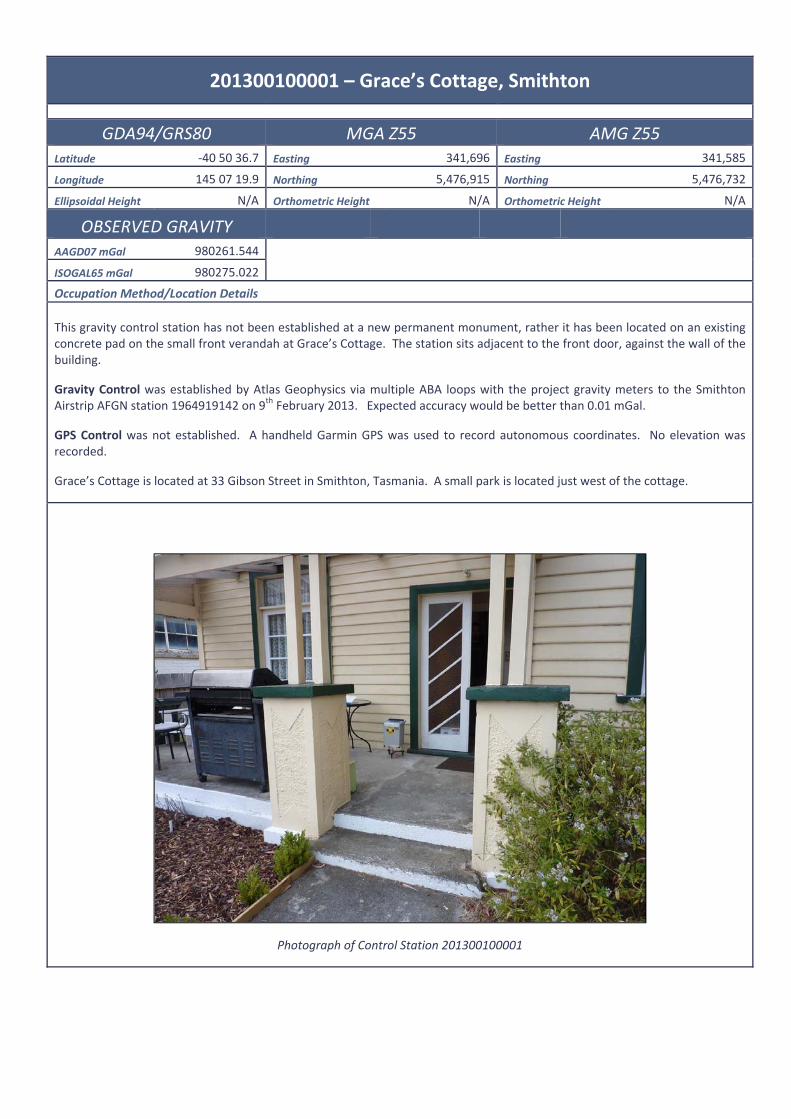
201300100001 – Grace’s Cottage, Smithton
GDA94/GRS80 MGA Z55 AMG Z55 Latitude -40 50 36.7 Easting 341,696 Easting 341,585
Longitude 145 07 19.9 Northing 5,476,915 Northing 5,476,732
Ellipsoidal Height N/A Orthometric Height N/A Orthometric Height N/A
OBSERVED GRAVITY AAGD07 mGal 980261.544
ISOGAL65 mGal 980275.022
Occupation Method/Location Details This gravity control station has not been established at a new permanent monument, rather it has been located on an existing concrete pad on the small front verandah at Grace’s Cottage. The station sits adjacent to the front door, against the wall of the building.
Gravity Control was established by Atlas Geophysics via multiple ABA loops with the project gravity meters to the Smithton Airstrip AFGN station 1964919142 on 9th February 2013. Expected accuracy would be better than 0.01 mGal.
GPS Control was not established. A handheld Garmin GPS was used to record autonomous coordinates. No elevation was recorded.
Grace’s Cottage is located at 33 Gibson Street in Smithton, Tasmania. A small park is located just west of the cottage.
Photograph of Control Station 201300100001

201300100002 – Waratah Water Wheel
GDA94/GRS80 MGA Z55 AMG Z55 Latitude -41 26 41.7 Easting 377,075 Easting 376,965
Longitude 145 31 42.4 Northing 5,410,804 Northing 5,410,620
Ellipsoidal Height N/A Orthometric Height N/A Orthometric Height N/A
OBSERVED GRAVITY AAGD07 mGal 980169.111
ISOGAL65 mGal 980182.659
Occupation Method/Location Details This gravity control station has not been established at a new permanent monument, rather it has been located on the corner of a concrete pad next to a water wheel/mill in Waratah.
Gravity Control was established by Atlas Geophysics via ABA loops with the project meters to AFGN station 1985911141 at the Devonport airport terminal on 13th February 2013 and 22nd February 2013. Expected accuracy would be better than 0.1 mGal.
GPS Control was not established. A handheld Garmin GPS was used to get autonomous coordinates. No elevation was recorded.
The water mill is easily accessible via an asphalt car park off Smith or Crosby Street, Waratah. A large lake sits just east of the car park.
Photograph of Control Station 201300100002

APPENDIX C GPS Control Information
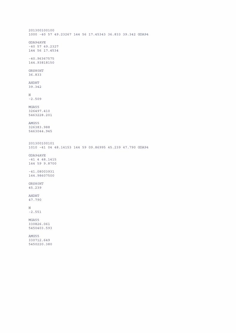
201300100100 1000 -40 57 49.23267 144 56 17.45343 36.833 39.342 GDA94 GDA94AVE -40 57 49.2327 144 56 17.4534 -40.96367575 144.93818150 GRS80HT 36.833 AHDHT 39.342 N -2.509 MGA55 326497.410 5463228.201 AMG55 326383.988 5463044.945 201300100101 1010 -41 04 48.14153 144 59 09.86995 45.239 47.790 GDA94 GDA94AVE -41 4 48.1415 144 59 9.8700 -41.08003931 144.98607500 GRS80HT 45.239 AHDHT 47.790 N -2.551 MGA55 330826.061 5450403.593 AMG55 330712.649 5450220.380

201300100103 1030 -40 56 56.66575 145 18 38.53076 60.550 62.491 GDA94 GDA94AVE -40 56 56.6658 145 18 38.5308 -40.94907383 145.31070300 GRS80HT 60.550 AHDHT 62.491 N -1.941 MGA55 357815.294 5465522.246 AMG55 357701.784 5465339.035 201300100108 1080 -40 57 53.05811 145 24 06.74485 160.314 162.087 GDA94 GDA94AVE -40 57 53.0581 145 24 6.7449 -40.96473836 145.40187358 GRS80HT 160.314 AHDHT 162.087 N -1.773 MGA55 365521.033 5463927.576 AMG55 365407.503 5463744.380
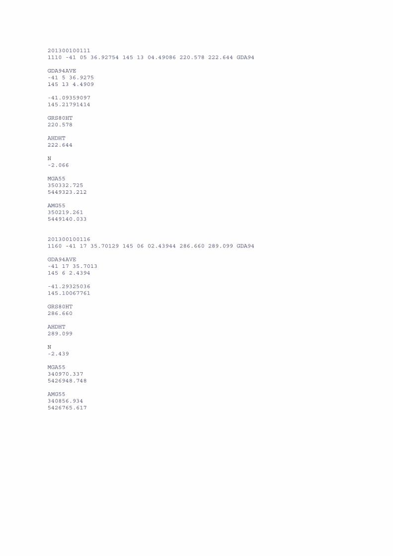
201300100111 1110 -41 05 36.92754 145 13 04.49086 220.578 222.644 GDA94 GDA94AVE -41 5 36.9275 145 13 4.4909 -41.09359097 145.21791414 GRS80HT 220.578 AHDHT 222.644 N -2.066 MGA55 350332.725 5449323.212 AMG55 350219.261 5449140.033 201300100116 1160 -41 17 35.70129 145 06 02.43944 286.660 289.099 GDA94 GDA94AVE -41 17 35.7013 145 6 2.4394 -41.29325036 145.10067761 GRS80HT 286.660 AHDHT 289.099 N -2.439 MGA55 340970.337 5426948.748 AMG55 340856.934 5426765.617
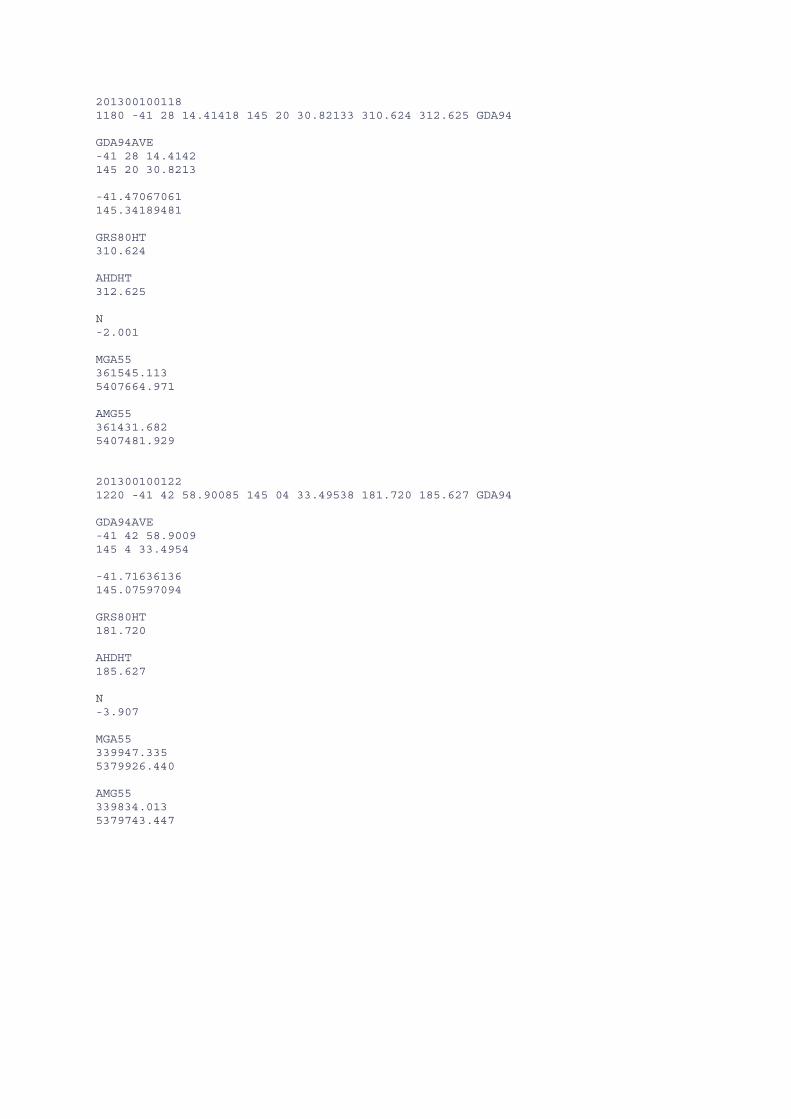
201300100118 1180 -41 28 14.41418 145 20 30.82133 310.624 312.625 GDA94 GDA94AVE -41 28 14.4142 145 20 30.8213 -41.47067061 145.34189481 GRS80HT 310.624 AHDHT 312.625 N -2.001 MGA55 361545.113 5407664.971 AMG55 361431.682 5407481.929 201300100122 1220 -41 42 58.90085 145 04 33.49538 181.720 185.627 GDA94 GDA94AVE -41 42 58.9009 145 4 33.4954 -41.71636136 145.07597094 GRS80HT 181.720 AHDHT 185.627 N -3.907 MGA55 339947.335 5379926.440 AMG55 339834.013 5379743.447

201300100204 2040 -41 10 43.39098 144 43 23.52290 85.222 88.543 GDA94 GDA94AVE -41 10 43.3910 144 43 23.5229 -41.17871972 144.72320081 GRS80HT 85.222 AHDHT 88.543 N -3.321 MGA55 309029.078 5438904.090 AMG55 308915.746 5438720.871 201300100210 2100 -41 03 36.77075 145 28 26.82633 335.745 337.231 GDA94 GDA94AVE -41 3 36.7708 145 28 26.8263 -41.06021411 145.47411842 GRS80HT 335.745 AHDHT 337.231 N -1.486 MGA55 371785.773 5453436.994 AMG55 371672.243 5453253.837
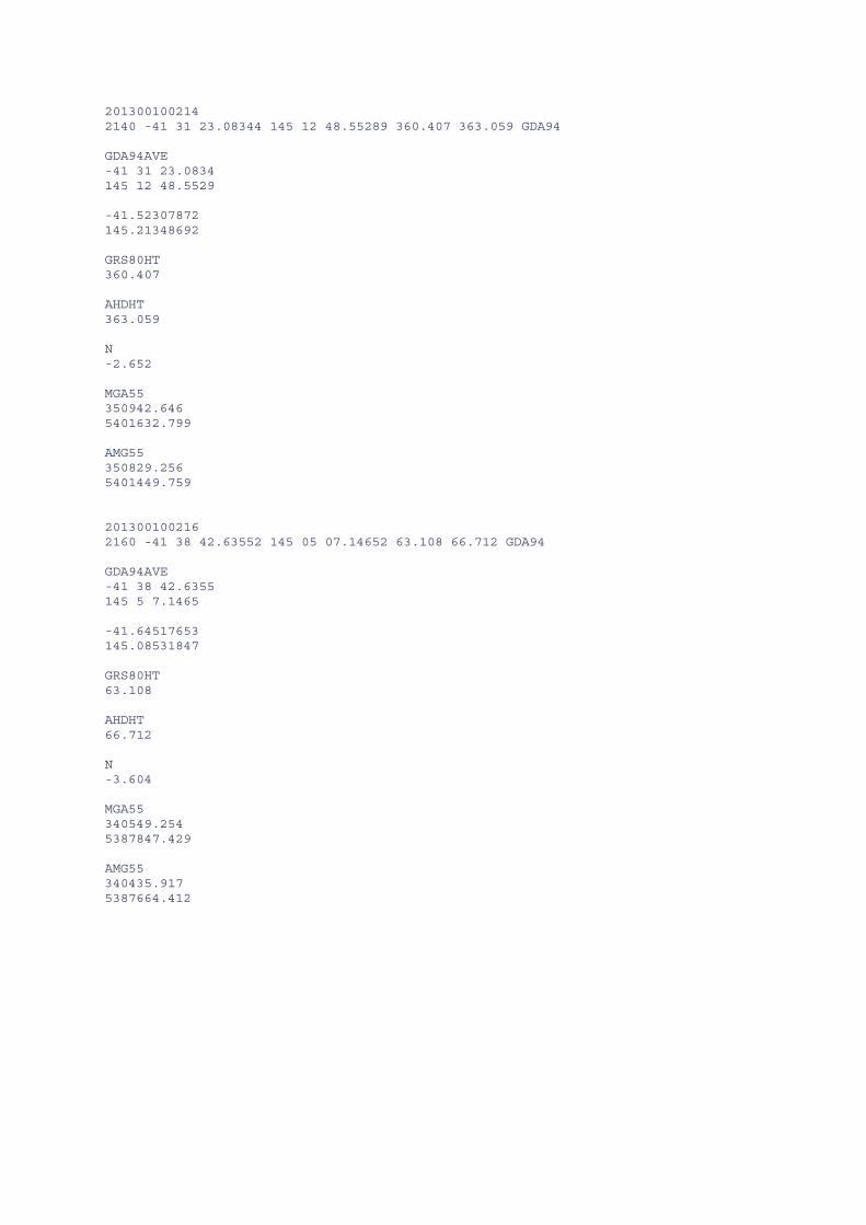
201300100214 2140 -41 31 23.08344 145 12 48.55289 360.407 363.059 GDA94 GDA94AVE -41 31 23.0834 145 12 48.5529 -41.52307872 145.21348692 GRS80HT 360.407 AHDHT 363.059 N -2.652 MGA55 350942.646 5401632.799 AMG55 350829.256 5401449.759 201300100216 2160 -41 38 42.63552 145 05 07.14652 63.108 66.712 GDA94 GDA94AVE -41 38 42.6355 145 5 7.1465 -41.64517653 145.08531847 GRS80HT 63.108 AHDHT 66.712 N -3.604 MGA55 340549.254 5387847.429 AMG55 340435.917 5387664.412

201300100218 2180 -40 58 23.69245 145 34 02.43894 114.477 116.034 GDA94 GDA94AVE -40 58 23.6925 145 34 2.4389 -40.97324792 145.56734414 GRS80HT 114.477 AHDHT 116.034 N -1.557 MGA55 379460.959 5463224.397 AMG55 379347.393 5463041.225 201300100221 2210 -41 10 12.79668 145 18 20.63081 410.260 411.978 GDA94 GDA94AVE -41 10 12.7967 145 18 20.6308 -41.17022131 145.30573078 GRS80HT 410.260 AHDHT 411.978 N -1.718 MGA55 357873.780 5440962.929 AMG55 357760.307 5440779.785

201300100222 2220 -41 09 46.85078 145 26 20.55255 181.742 183.180 GDA94 GDA94AVE -41 9 46.8508 145 26 20.5526 -41.16301411 145.43904239 GRS80HT 181.742 AHDHT 183.180 N -1.438 MGA55 369042.854 5441972.251 AMG55 368929.349 5441789.122 201300100224 2240 -41 11 09.06201 145 26 52.69101 193.898 195.296 GDA94 GDA94AVE -41 11 9.0620 145 26 52.6910 -41.18585056 145.44796972 GRS80HT 193.898 AHDHT 195.296 N -1.398 MGA55 369837.065 5439450.382 AMG55 369723.561 5439267.261

APPENDIX D Gravity Control Processing and Information

201300100001 GRAVITY TIES
1 = 201300100001 Grace's Cottage Smithton 9142 = 1964919142 Smithton Airport Terminal Ties carried out by vehicle
METER A5 station gda94_longitude_dd gda94_latitude_dd date_ddmmyyyy time_hhmmss dialrdng_mgal etc_mgal obsg_mgal metersn
1 145.083000 -40.830000 09/02/2013 06:36:23 4767.043 -0.091 980000.000 40361 1 145.083000 -40.830000 09/02/2013 06:37:29 4767.043 -0.091 980000.001 40361
9142 145.122194 -40.843528 09/02/2013 06:54:11 4768.054 -0.085 980001.026 40361 9142 145.122194 -40.843528 09/02/2013 06:55:17 4768.054 -0.084 980001.027 40361
1 145.083000 -40.830000 09/02/2013 07:09:42 4767.013 -0.078 980000.000 40361 1 145.083000 -40.830000 09/02/2013 07:09:42 4767.013 -0.078 980000.000 40361 1 145.083000 -40.830000 09/02/2013 07:10:48 4767.016 -0.077 980000.004 40361
9142 145.122194 -40.843528 09/02/2013 07:30:18 4768.022 -0.066 980001.026 40361 9142 145.122194 -40.843528 09/02/2013 07:31:24 4768.025 -0.066 980001.030 40361
1 145.083000 -40.830000 09/02/2013 07:45:16 4766.982 -0.057 979999.999 40361 1 145.083000 -40.830000 09/02/2013 07:46:22 4766.982 -0.056 980000.000 40361
METER A8 station gda94_longitude_dd gda94_latitude_dd date_ddmmyyyy time_hhmmss dialrdng_mgal etc_mgal obsg_mgal metersn
1 145.083000 -40.830000 09/02/2013 06:26:08 4161.410 -0.094 980000.000 40826 1 145.083000 -40.830000 09/02/2013 06:27:14 4161.405 -0.094 979999.995 40826
9142 145.122194 -40.843528 09/02/2013 06:54:46 4162.426 -0.085 980001.027 40826 9142 145.122194 -40.843528 09/02/2013 06:55:52 4162.426 -0.084 980001.027 40826
1 145.083000 -40.830000 09/02/2013 07:16:16 4161.388 -0.075 980000.000 40826 1 145.083000 -40.830000 09/02/2013 07:16:16 4161.388 -0.075 980000.000 40826 1 145.083000 -40.830000 09/02/2013 07:17:22 4161.385 -0.074 979999.998 40826
9142 145.122194 -40.843528 09/02/2013 07:30:35 4162.408 -0.066 980001.029 40826 9142 145.122194 -40.843528 09/02/2013 07:32:55 4162.406 -0.065 980001.029 40826
1 145.083000 -40.830000 09/02/2013 07:53:08 4161.360 -0.052 979999.998 40826 1 145.083000 -40.830000 09/02/2013 07:54:14 4161.361 -0.051 980000.000 40826
AVG 9142 980001.028 DIFF 9142_1 1.028 KNOWN 9142 AAGD07 980262.572 KNOWN 9142 ISOGAL65 980276.050 CALC 1 AAGD07 980261.544 CALC 1 ISOGAL65 980275.022

201300100002 GRAVITY TIES
1 = 201300100001 Grace's Cottage Smithton 2 = 201300100002 Waratah Water Wheel 9142 = 1964919142 Smithton Airport Terminal 1141 = 1985911141 Devonport Airport Terminal Ties carried out by vehicle
METER A5 station gda94_longitude_dd gda94_latitude_dd date_ddmmyyyy time_hhmmss dialrdng_mgal etc_mgal obsg_mgal metersn
2 145.528465 -41.444936 13/02/2013 14:11:23 4676.893 0.054 980000.000 40361 2 145.528465 -41.444936 13/02/2013 14:12:59 4676.893 0.054 980000.000 40361
1141 146.426360 -41.171830 13/02/2013 16:28:55 4778.611 0.035 980101.712 40361 1141 146.426360 -41.171830 13/02/2013 16:30:01 4778.612 0.035 980101.712 40361
2 145.528465 -41.444936 13/02/2013 18:08:25 4676.946 -0.020 980000.000 40361 2 145.528465 -41.444936 13/02/2013 18:08:25 4676.946 -0.020 980000.000 40361
METER A8 station gda94_longitude_dd gda94_latitude_dd date_ddmmyyyy time_hhmmss dialrdng_mgal etc_mgal obsg_mgal metersn
2 145.528465 -41.444936 13/02/2013 14:26:43 4072.704 0.056 980000.000 40826 2 145.528465 -41.444936 13/02/2013 14:27:57 4072.706 0.056 980000.002 40826
1141 146.426360 -41.171830 13/02/2013 16:29:58 4174.450 0.035 980101.732 40826 1141 146.426360 -41.171830 13/02/2013 16:31:12 4174.450 0.034 980101.732 40826
2 145.528465 -41.444936 13/02/2013 17:59:58 4072.762 -0.015 980000.000 40826 2 145.528465 -41.444936 13/02/2013 17:59:58 4072.762 -0.015 980000.000 40826
2 145.528465 -41.444936 22/02/2013 07:09:30 4080.568 -0.007 980000.000 40826 2 145.528465 -41.444936 22/02/2013 07:10:56 4080.570 -0.006 980000.003 40826
1141 146.426360 -41.171830 22/02/2013 08:45:48 4182.252 0.049 980101.749 40826 1141 146.426360 -41.171830 22/02/2013 08:46:54 4182.249 0.050 980101.747 40826
2 145.528465 -41.444936 22/02/2013 10:35:10 4080.450 0.092 980000.000 40826 2 145.528465 -41.444936 22/02/2013 10:35:10 4080.450 0.092 980000.000 40826
AVG 1141 980101.731 DIFF 1141_1 101.731 KNOWN 1141 AAGD07 980270.842 KNOWN 1141 ISOGAL65 980284.390 CALC 1 AAGD07 980169.111 CALC 1 ISOGAL65 980182.659

Check to Smithton A/S 2 145.528465 -41.444936 26/02/2013 07:07:32 4084.112 -0.093 980000.000 40826 2 145.528465 -41.444936 26/02/2013 07:08:38 4084.111 -0.093 979999.999 40826
9142 145.122194 -40.843528 26/02/2013 16:26:36 4177.436 0.013 980093.474 40826 9142 145.122194 -40.843528 26/02/2013 16:27:42 4177.437 0.012 980093.475 40826
2 145.528465 -41.444936 26/02/2013 18:42:29 4084.041 -0.078 980000.000 40826 2 145.528465 -41.444936 26/02/2013 18:43:34 4084.041 -0.078 980000.000 40826
AVG 1 980093.475 DIFF 2_1 93.475 KNOWN 9142 AAGD07 980262.572 KNOWN 9142 ISOGAL65 980276.050 diff mGal CALC 1 AAGD07 980169.098 -0.014 CALC 1 ISOGAL65 980182.576 -0.084

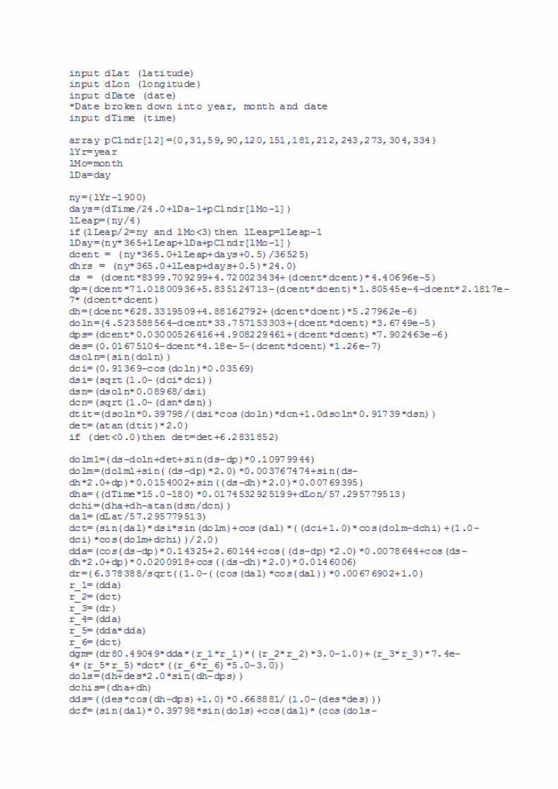
APPENDIX E Longman’s Earth Tide Correction Formula

APPENDIX F Data Format

ATLAS FORMAT
Field Header Field Description Format Units PROJECT Atlas Geophysics Project Number A9 None STATION Unique Station ID I8 None STATIONCODE Unique Station Code A13 None LINE Line ID I8 None TYPE Observation Type : Base, Field or Repeat A8 None MGAEAST Coordinate Easting MGA94/GDA94 F11.3 m MGANORTH Coordinate Northing MGA94/GDA94 F12.3 m ZONE MGA Zone Number F8.0 NA GDA94LAT Coordinate Latitude GDA94 F15.10 DD GDA94LONG Coordinate Longitude GDA94 F15.10 DD ORTHOHTM Coordinate Elevation Orthometric F9.3 m GRS80HTM Coordinate Elevation Ellipsoidal F9.3 m NAG09 Geoid Separation AUSGEOID09 F8.3 m AMG84EAST Coordinate Easting AMG84 F11.3 m AMG84NORTH Coordinate Northing AMG84 F12.3 m DATE Observation Date I8 None TIME Observation Time I8 None DIALMGAL Gravity Dial Reading F9.3 mGal ETCMGAL Earth Tide Correction (Longman) F8.3 mGal SCALE Scale Factor Applied to Dial Reading F9.6 None OBSG84MGAL Observed Gravity ISOGAL84 F11.3 mGal OBSG84GU Observed Gravity ISOGAL84 F11.2 gu OBSGAAGD07GU Observed Gravity AAGD07 F13.2 gu OBSGAAGD007MGAL Observed Gravity AAGD07 F16.3 mGal DRIFTMGAL Drift Applied to Dial Readings F10.3 mGal TGRAV67GU Theoretical Gravity 1967 F11.2 gu TGRAV67MGAL Theoretical Gravity 1967 F12.3 mGal TGRAV80GU Theoretical Gravity 1980 F11.2 gu GFACGU Geoidal Free Air Correction F8.2 gu GFACMGAL Geoidal Free Air Correction F9.3 mGal GFAAGU Geoidal Free Air Anomaly F8.2 gu GFAAMGAL Geoidal Free Air Anomaly F9.3 mGal GBC267GU Geoidal Bouguer Correction 2.67 tm^-3 F9.2 gu GBC240GU Geoidal Bouguer Correction 2.40 tm^-3 F9.2 gu GBC220GU Geoidal Bouguer Correction 2.20 tm^-3 F9.2 gu GBC267MGAL Geoidal Bouguer Correction 2.67 tm^-3 F11.3 mGal GBC240MGAL Geoidal Bouguer Correction 2.40 tm^-3 F11.3 mGal GBC220MGAL Geoidal Bouguer Correction 2.20 tm^-3 F11.3 mGal GBA267GU Geoidal Bouguer Anomaly 2.67 tm^-3 F9.2 gu GBA240GU Geoidal Bouguer Anomaly 2.40 tm^-3 F9.2 gu GBA220GU Geoidal Bouguer Anomaly 2.20 tm^-3 F9.2 gu GBA267MGAL Geoidal Bouguer Anomaly 2.67 tm^-3 F11.3 mGal GBA240MGAL Geoidal Bouguer Anomaly 2.40 tm^-3 F11.3 mGal GBA220MGAL Geoidal Bouguer Anomaly 2.20 tm^-3 F11.3 mGal TGRAV80ACGU Theoretical Gravity 1980 Atmospheric Corrected F11.2 gu EFACGU Ellipsoidal Free Air Correction F9.2 gu EFAAGU Ellipsoidal Free Air Anomaly F8.2 gu SCBC267GU Spherical Cap Bouguer Correction 2.67 tm^-3 F10.2 gu SCBC240GU Spherical Cap Bouguer Correction 2.40 tm^-3 F10.2 gu SCBC220GU Spherical Cap Bouguer Correction 2.20 tm^-3 F10.2 gu SCBA267GU Spherical Cap Bouguer Anomaly 2.67 tm^-3 F10.2 gu SCBA240GU Spherical Cap Bouguer Anomaly 2.40 tm^-3 F10.2 gu SCBA220GU Spherical Cap Bouguer Anomaly 2.20 tm^-3 F10.2 gu SCBA267MGAL Spherical Cap Bouguer Anomaly 2.67 tm^-3 F12.3 mGal SCBA240MGAL Spherical Cap Bouguer Anomaly 2.40 tm^-3 F12.3 mGal SCBA220MGAL Spherical Cap Bouguer Anomaly 2.20 tm^-3 F12.3 mGal TCINNERGU Inner Terrain Correction F8.2 gu TCINNERMGAL Inner Terrain Correction F8.3 mGal QFINNER Quality Factor Inner TC I2 None TCOUTERGU Outer Terrain Correction F8.2 gu TCOUTERMGAL Outer Terrain Correction F8.3 mGal QFOUTER Quality Factor Outer TC F2 None TCTOTALGU Total Terrain Correction F8.2 gu TCTOTALMGAL Total Terrain Correction F8.3 mGal CGBA267GU Complete Geiodal Bouguer Anomaly 2.67 tm^-3 F11.3 gu CGBA267MGAL Complete Geiodal Bouguer Anomaly 2.67 tm^-3 F11.3 mGal CSCBA267GU Complete Spherical Cap Bouguer Anomaly 2.67 tm^-3 F12.2 gu CSCBA267MGAL Complete Spherical Cap Bouguer Anomaly 2.67 tm^-3 F12.2 mGal DIFFEASTM Repeat Error for Easting Observation F8.3 m DIFFNORTHM Repeat Error for Northing Observation F8.3 m DIFFHTM Repeat Error for Elevation Observation F8.3 m DIFFOBSGMGAL Repeat Error for Observed Gravity F8.3 mGal DIFFOBSGGU Repeat Error for Observed Gravity F8.2 gu METERSN Serial Number of Gravity Instrument I8 None CLOSUREGU Loop Closure in gu F8.2 gu CLOSUREMGAL Loop Closure in mGal F8.3 mGal GRVBASE Gravity Base A11 None GPSBASE GPS Base A11 None

MRT FORMAT
Field Header Field Description Format Units STATION Unique Station ID I8 None ZONE UTM Zone Number F8.0 NA AMGEAST Coordinate Easting AMG66 F11.3 m AMGNORTH Coordinate Northing AMG66 F12.3 m ORTHOHTM Coordinate Elevation Orthometric F9.3 m OBSG65MGAL Observed Gravity ISOGAL65 F11.3 mGal GBA267MGAL Geoidal Bouguer Anomaly 2.67 gm/cc F11.3 mGal MGAEAST Coordinate Easting MGA94/GDA94 F11.3 m MGANORTH Coordinate Northing MGA94/GDA94 F12.3 m GDA94LAT Coordinate Latitude GDA94 F15.10 DD GDA94LONG Coordinate Longitude GDA94 F15.10 DD GRS80HTM Coordinate Elevation Ellipsoidal F9.3 m NAG09 Geoid Separation AUSGEOID09 F8.3 m DATE Observation Date I8 None TIME Observation Time I8 None GRVBASE Gravity Base A11 None GPSBASE GPS Base A11 None