r ml technical report - defense technical … · r ml technical report ... rotor downwash to obtain...
TRANSCRIPT

r
r
Ml TECHNICAL REPORT
THE FEASIBILITY AND USE OF ANTi-TORQUE
SURFACES IMMERSED IN HELICOPTERROTOR DOWNWASH
by: C. Tung, J.C. Erickson, Jr. and F,A. DuWaldt
51 CAL No. BB-2584-S-2
SIPrepared for:
Office of Naval ResearchAeronauticsCode 461Arl~ngton, Virginia 22217 "
Contract N00014-68-C-0241 "
NR 212-182
February 1970
Reproduction in whole o. in partis permitted for any purpose ofthe United States Government.
This document has been approvedfor public release and sale; itsdistribution is unlimited.
CORNELL AERONAUTICAL LABORATORY, INC.OF CORNELL UNIVERSITY, BUFFALO, N. Y. 14221
Roptoducod by (NATIONAL TECHNICALINFORMATION SERVICE ....SPtlngfiold, Va. 22151 [t

I
CORNELL AERONAUTICAL LABORATORY, INC.BUFFALO, NEW YORK 14221
r
THE FEASIBILITY AND USE OF ANTI-TORQUE SURFACESIMMERSED IN HELICOPTER ROTOR DOWNWASH
by
C. Tung, .. C. Erickson, Jr. and F.A. DuWaldt
CAL REPORT BB-2584-S-2D
CONTRACT N00014.68-C.0241 FNR212-182 D EC 11 1970
FEBRUARY 1970 IiLtSr." Lht hLr
BReproduction in whole or in partis permitted for any purpose ofthe United States Government
Prepared for:
OFFICE OF NAVAL RESEARCHAERONAJTICS
CODE 451ARLINGTON, VIRGINIA 22217
This document has been approved for publicrelease and sale; its distL'ibution is unlimited.

SUMMARY
Losses of helicopter tail rotors occur with sufficient frequency to
justify the search for a substitute system or, at least, an emergency device
that would perirdt flight continuation (power on) and landing. CAL has shown
previously that the use of aerodynamic surfaces immersed in the main rotor
downwash to balance engine torque in the hovering flight mode is impractical
in the sense that very large surface areas would be required. The current
study is addressed to the problem of maintaining torque trim in the forward
flight mode where the flight speed contributes to the dynamic pressure acting
on the surface. It is shown that added surfaces giving total areas equal to
about 2% of the main rotor disk area would provide torque trim for speeds
above about 75 ft/sec for representative current vehicles. This capability
should permit a roll-on powered landing in the event of tail-rotor failure.
The required surface size is not, itself, so great as to be imprac-
tical. Location and distribution of the surface area, however, is a problem
if surfaces are to be retrofitted to man, existing helicopters since the most
effective location would probably be limited due to clearances between mechani-
cal components. Therefore, incorporation of the tail boom as part of the tail
area and introduction of active systems like jet flaps or movable surfaces to
increase the achievable lift coefficient are considered. It is concluded that
potential gains in safety margins, aural detectability, vibration and fatigue
life of the ta.il rotor blades can be realized with carefully designed anti-torque
augmenters. However, their use should be anticipated in the original design
layout of the vehicle.
Recommendations are made for further design studies and
experimental measurements.
ii BB-2584-S-2

I
TABLE OF CONTENTSIPage
SUMMARY ii
LIST OF ILLUSTRATIONS iv
I LIST OF SYMBOLS vi
r I. INTRODUCTION I
II. TORQUE REQUIREMENTS 3
2. 1 High Speed Flight Conditions - UH-IB 3
2.2 Generalization of High Speed Flight Conditions 6
2.3 Examples Based on Representative Helicopters 7
III. AERODYNAMIC CHARACTERISTICS OF ANTI-TORQUE 10SURFACES
3. 1 Fixed Surfaces t0
3.2 Summary of Capabilities and Limitations of 13Fixer! Surfaces
3. 3 Movable Surfaces and High Lift Devices 14
IV. DISCUSSION AND CONCLUSIONS 19
V. RECOMMENDATIONS 22
VI. REFERENCES 23
APPENDIX A - POWER REQUIRED FOR A ROTOR 26
APPENDIX B - LIFT COEFFICIENT FOR FINNED ELLIPSE 28
APPENDIX C - FLAPPED FUSELAGE 30
DISTRIBUTION LIST
iii BB-2584-S-2

L
LIST OF ILLUSTRATIONS
Figure Page
1 Anti-Torque Moment Available from AerodynamicSurfaces to Balance Main Rotor Torque - BellUH-IB Helicopter, 6550 lb gross weight, 314 RPM 32
2 Flight Velocity for Minimum Power, V,..i,as aFunction of Sectional Drag Coefficient, Cd, ,Solidity, a- , Tip Speed, Vt , and EquivalentFlat Plate Area Ratio, fI/ 33
3 Minimum Power, , as a Function of SectionalDrag Coefficient, CA, , Solidity, a- , Tip Speed,
Vt , and Equivalent Flat Plate Area Ratio, 4/f 34
4 Anti-Torque Performance of a 2% Tail - Power, Pas a Function of Flight Velocity for Minimum Power,vmn, and Tip Speed, V,
5 Schematic Diagram of a UH-IC With IncreasedTail Area 36
6 Possible OH-6A Modifications 37
7 Possible UH-2 Modifications 38
8 Possible SH-3D Modifications 39
9 Possible CH-53A Modifications 40
10 Possible UH-IC Modifications 41
11 (a) Effects of Aspect Ratio on Variationof Lift Coefficient With Angle ofAttack. Rectangular Tips.0 0 Yaw(Data from Reference 16) 42
(b) Effects of Aspect Ratio on Variation ofLift Coefficient With Angle of Attick.Semicircular Tips. 00 Yaw (Data fromReference 16) 42
12 Aerodynamic Characteristics of NACA 66(215)-216 Airfoil Section With 0. 20c Sealed Plain Flap(Reference 17) 43
iv BB-2584-S-2

Figure Page
13 Theoretical and Experimental Part-Span LiftFactors for Two Models (Reference 18) 44
14 A Schematic Diagram of a UH-IA Profile withthe More Important Dimensions Labeled 45
15 The Intersection of the Curves of F and F
With Cd o= 0. 013, /Al = 0.01, and a- tl./I)Varying Between 0. 8 and 3. 6 46
16 Flapped Fuselage of Elliptical Cross-Section in Transformed and PhysicalPlane 47
17 Flapped Fuselage of Circular Cross-Section in Transformed and PhysicalPlane 48
-BB-2584-S-2

LIST OF SYMBOLS
main rotor disk area, ft.2
2rotor blade area, ft.
aspect ratio
6L. major axis of an ellipse, ft.
minor axis of an ellipse, ft.
CL lift coefficient
CL lift coefficient of finite span surface
C, maximum lift coefficient
C,. = lift coefficient of infinite span surface
= dC/dc
CT thrust coefficient
Cg~o sectional drag coefficient
F part-span lift factor
F anti-torque force, lbs.
2: flat plate area, ft.
K1 ground clearance of fuselage-tail boomjuncture, ft. (Figure 14)
K 2 ground clearance of tail skid, ft. (Figure 14)
Ks hub height relative to tail boom, ft. (Figure 14)
= , half distance from ellipse centerto focus, ft.
-it distance between center of force and the rotorshaft axis, ft.
-, iength of fin on the upper side of the fuselage, ft.
length of fin on the lower side of the fuselage, ft.
vi BB-2584-S-2

I
t)fl transformed length of.,, ft.
r Yfl2 transform,.d length of 4, ft.
P power, horsepower
!PM, minimum power required for flight, horsepower
P power corresponding to torque that can be balancedby a vertical tail of area 0. 02A , horsepower
p semi-perimeter/span
main rotor torque, ft. lbs.
P radius of the rotor blade, ft.
St area of vertical tail, ft. 2
Sjo original area of vertical tail, ft.
T thrust, lbs.
U incoming flow velocity, ft. /sec.
V flight speed, ft. /sec.
\],i speed at which the powerF, required for flightis a minimum, ft. /sec.
V, slipstream velocity, ft. /sec.
Vt tip velocity, ft. /sec.
if induced velocity, ft. /sec.
W weight of the aircraft, lbs.
O angle of attack (related to the near wake twistparameter of Rcference 1)
06 SRL angle oi attack at stall
8 angle of the axis of vortex cores with respectto the freestream
0 circulation at mid-span, ft. /sec.
yaw angle of incoming flow
vii BB-2584-S-2
L-vi
advance ratio
o density of air, slugs/ft.
12 rotor rotational speed, rad. /sec.
Z: twist angle of Reference 1, ratio of swirl velocityto inflow velocity
solidity, ratio of blade area to disk area
iV
I

I. INTRODUCTION
Tail rotors on helicopters appear to be major factors in accidents
and vehicle maintenance cost. Further, they are important noise and
vibration sources. The objective of this investigat.on is the determination
of the feasibility of using fixed aerodynamic surfaces immersed in the main
rotor downwash to obtain helicopter anti-torque mo-nentt. It was determined
in a prior study (Reference 1) that the replacement of the standard tail rotor
on a helic )ter by a fixed aerodynamic surface is not practical. The thesis
of that study was that the high velocity slipstream regicns underneath a rotor
could provide sufficient dynamic pressure to permit the generation of rela-
tive.ly large lifts, and that these lifts could be vectored to provide anti-torque
moments for the machine. The most stringent flight condition was inspected,
namely, hovering within ground effect. Slirstrearm flow fields calculated
previously (References 2-7) were used ±or the purpose of estimating aero-
dynamic forces, and it was found that the anti-torque function could be
carried out by a suitably placed surface. This surface area appeared to be
too large for operational application. On the other hand, in view of tLe
rather conservative choice of lift coefficient, combined with the severe
requirement of tail-rotor elimination, the calculations could not be con-
sidered as being all conclusive. That is, no close definition of the surface
location and form had been made--and, hence, no limits on achievable
forces had been designated- -which would indicate the operating regime in
which a practical surface would be effective. This has been done in the
study reported here. The relationship between physical parameters of the
vehicle, flight conditions, and specified tail size have been established
under the postulate of small auxiliary surfaces on the helicopter fuselage
for the purpose of augmenting the tail rotor.
The tail rotor is an efficient component in the hovering flight
condition. In high speed flight, however, conventional aerodynamic surfaces
become efficient force generators while the auxiliary disadvantages of tail
rotors become more severe due to factors such as noise, vibration,
1 BB-2584-S-2

In
reliability and vulneability. Consequently, there might be some advantage
to providing a vertical tail that permits ti'e unloading of the tail rotor and
affords some anti-torque moment reserve in the event of loss of the tail
rotor. Most current helicopters have at least a rough approximation to such
a surlace in the fairing normally built around the tail rotor support structure.
In the following sections the feasibility of using a relatively small
convenLional surface to provide anti-torque moments is established for the
high speed flight condition--i. e. , for flight velocities in excess of about 753 ft/sec. Both particular and generalized results are presented, and the pos-
sible shape of the surface is considered. It is noted that required surface
size is not, itself, so great as to be impractical. Location and distribution
of the surface area is, however, a problem if surfaces are to be retrofitted
since the most effective location would probably be limited due to existing
clearances between mechanical components.
No consideration was given to the effects of side gusts although
this factor must be inspected eventually. Side gusts on the added surfaces
can be expected to provide one of the control power conditions that must be
met. Additionally, a lateral-longitudinal coupling might result due to the
form of the pressure distribution on the tail and fuselage combination.I
Incorporation of the tail boom as part of the tail area and intro-
duction of circulation control to increase the achievable lift coefficient are
considered. Direct power expenditure is inplied for the jet-flap configura-
Ition. It is concluded that potential gains in safety margins, aural detectability,
vibration and fatigue life of the tail rotor blades can be realized with carefully
Idesigned anti-torque augmenters. However, their use should be anticipated
in the original design layout of the vehicle.
I
2BB-2584-S-2
I

II. TORQUE REQUIREMENTS
It was found in Reference I that aerodynamic surfaces"' with
areas about thirty-five percent of the rotor disk area would be required for
complete anti-torque balance of a typical vehicle hovering in ground effect.
j Since surfaces of this size are impractical, it was concluded that complete
elimination of the tail rotor cannot be achieved in practice by conventional
f aerodynamic surfaces alone. There iemains the question of the extent to
which the tail rotor can be unloaded at flight conditions, other than lift-off
and hover, through the use of aerodynamic surfaces that are a few percent
of the rotor disk area in size.
2. 1 High-Speed Flight Conditions - UH-IB
The present phase of the investigation was devoted to high-speed
flight conditions, i. e. , those in which the flight speed V of the helicopter
is above the speed V at which the power P required for flight is a minimum,
say P,,. Since we are concerned with torque balance, it is more useful
to consider the power-required curves in terms of the main rotor torque
Q which must be counteracted for moment equilibrium. The torque is
related simply to the power required by the rotor rotational speed, namely,
P= QR2. For steady-state equilibrium, the anti-torque moment required is
equal to Q , i.e.,
Fi (1)t t
where
F,. = anti-torque force in lbs.
I divance between center of forceand the rotor shaft axis
Operating at CL 1
3 BB-2584-S-2

I-
U
If a tail surface is to furnish the anti-torque moment,
"- - (V?+ C t(2)FF -T(V + IT) C's,
where
j 9 = density of air lb-sec /ft
V = helicopter forward speed, ft/se .
f = induced velocity, ft/sec
Ci. = lift coefficient
., = area of vertical tail, ft2
Equations (1) and (2) give
_V 1T2 CL it 'St V ' 3
where
R = 7rR a = main rotor disk area
R = radius of the rotor blade
Calculations were made for a UH-lB to illustrate the above
development. Rotor torque required (based on the power-required curve
given in Reference 8) as a function of forward speed for the Bell UH-lB is
given in Figure 1. The anti-torque moment available from aerodynamic
surfaces completely immersed in the rotor downwash is also plotted in
Figure I for three values of the nondimensional parameter
For a given value of ,/ , the aerodynamic surface will
exactly balance the rotor torque for that value of V where the corresponding
curve intersects the anti-torque-moment-required curve. Above that Vthe C. would be reduced to provide trim for a given Jt and S, and a force
margin would be available for maneuvers. For - 1.213 (which
4j.

L
r corresponds to the position of the UH-lB tail rotor axis) and CL. 1. 0, anI of 0.02 (i. e., two percent of rotor disk area) would balance the torque
for all flight speeds above 75 ft/sec. This velocity is very close to V,- .Tevl00073 ( ( M &
The present tJH-lB vertical tail has a value of t RR
0. 00885 for CL = 1 on Figure 1) which just manages to balance the entire
rotor torque near its maximum speed. Thus, for a threefold increase in
tail area, the speed at which the torque is completely balanced will be
reduced from the maximum speed of the helicopter to V . Redesign of
the geometry of the tail might provide a CL greater than 1. 0 and, hence,
permit use of a smaller area. Therefore, the tail rotor can be unloaded
completely at speeds above 75 ft/sec, so far as anti-torque balance is
concerned, by a reasonably sized vertical tail surface. Moreover, in the
event of complete loss of the tail rotor at speeds above 75 ft/sec, as can
occur for many reasons including foreign-object damage (Reference 9), such
a tail surface would permit fully powered flight to speeds as low as 75 ft/sec.
This speed is approximately the maximum speed for which a UH-IB can land
on smooth ground without structural failure of the landing gear, as indicated
by the height-velocity (H-V) diagram for this vehicle (Reference 10).
Furthermore, this powered-flight capability should provide the pilot with
sufficient flexibility for entering autorotation to permit landing at even lower
speeds because of the practically negligible torque that must be balanced
in the autorotational flight condition.
Results presented above establish the feasibility of increasing tail
surface size for a particular configuration. Generalization of the analysis
is presented in Section 2. 2. In particular, V and P have been determined
for general helicopter configurations based on a relatively simple power-
required equation. As an example, the entire power-required curve has been
worked out for the UH-lB and is presented as anti-torque moment required
in Figure 1. The predicted Q,: is in excellent agreement with the flight-
test value, although the corresponding predicted V. is considerably higher
than the test value. However, the torque-required curves are relatively
flat around ' Therefore, the error in the velocity at which a tail surface
5 BB-2584-S-2

would become efP.ctive is not large.2.2 Generalization of High-Speed Flight Conditions
The feasibility of increasing tail surface size for a particular
configuration was established in the previous section. This type of informa-
tion may be generalized. In particular,Vm, and ,have been determined
for a generaL helicopter configurations based on a relatively simple power-required equation (Reference 11). It is shown in Appendix A that the
governing parameters for the power required are W , V. , C, , V, , r and
T/A whereW is the weight of the craft; V, is the momentum-averaged value
of the main rotor induced velocity in hover; Ct,, is the mean rotor blade
sectional profile drag coefficient; V, is the rotor tip speed; cr is the solidity
and;/ is the ratio of the fuselage equivalent-flat-plate-area to the rotor disk
azi a. Computations of V,; and 11Lhave been made for a broad range of
parameters that are typical of existing and presently envisioned helicopters.
For example, o 0.013 (Reference 1Z, Figure 5); a- = 0.05 to 0. 12; V/v-
16 to 30; and f/P = 0. 0060 to 0. 014 (Reference 13, Figure 1). A useful working
chart can be obtained by using these parameters. For example, Figure 2
shows V,., /V. versus C- (V/V.)with f/P as a parameter. Given -, V
and /i we can calculate '(V,.) Then V],/V can be read directly from
Figure 2 for given f/. For this V,',/V , Figure 3 shows the corresponding
Pj, /WV . Several examples will be given in the next section to illustrate
the use of these curves.
If CL is assumed to be one, " Equation (3) may be written, throughthe relation P-'12 and 7=-2 as
.I S a P (4)
l ':'It should be noted that in order to derive Equation (4), the lift coefficient
zis assumed to be one. Methods for achieving or even possibly exceedingthis value are discussed in Section 3. 3 (Movable Control Surfaces andHigh Lift Devices)
6 BB-2584-S-2
it~"I +_ __

N
Although the area ratio S,/9 is used in the previous section, it may be
more convenient to use tail volume, TV = 4 5t , as a more appropriate
parameter to represent any given anti-torque surface. T, is limited to
two percent of rotor disk area times the rotor radius and substituting
V /V (from Appendix A) in this equation, one obtains
W4
[where P is called the upper bound power required to be balanced by the
tail volume at two percent of RP . Figure 4 shows Fi/'V. against VV.
with VA/ as a parameter. This figure may serve as a guide as to
whether or not the PIi /V for a typical helicopter flying at V/',/ can
be balanced by two percent of Rf. It will show in the next section that
several existing helicopters do indeed meet this requirement.
2. 3 Some Examples Based on Representative Helicopters
The Hughes OH-6A, the Kaman UH-ZC, the Sikorsky SH-3D and
the Sikorsky CH-53A are used as examples (the Bell UH-IB was treated
in the previous section). The following table shows tne physical parameters
and estimated aerodynamic parameters for these vehicles.
VEHICLE
ITEM OH-6A UH-2C SH-3D CH-53A
WEIGHT, W, LBS. 2400 9600 18600 33000
DISC AREA, A, FT2 544 1520 3020 4070
NO. OF BLADES, Nb 4I 4 5 6
SOLIDITY, o- 0.054 0.104 1 0.073 0.115
FUSELAGEFLAT PLATE AREA, f, FT2 7 13 31 44
TIP SPEED, Vt, FT/SEC 646 640 700 700
BLADE PROFILE DRAG IiCOEFFICIENT, Cd,o 0.013 0.013 0.013 0.0 3
7 BB-2584-S-2

In order to calculate the V , the density = 0. 00234 slugs/ft3
is used for all the computations. According to the lormulas in Section 2,
the parameters such as V. ,/Vo , f/R and" Vt/V are computed to be the
following:
IVEHICLEITEN OH-6A U-2C SH-3 CH-53A
V , (ft/sec) 30.7 36.7 36.2 41.6
Vt/V 0 21.0 17.5 19.3 16.8
f/A 0.0130 0.0085 0.C100 0.0110vt/V 0 1.13 1.82 .11 1 ,9t
By using the above tabulated numbers, we find V /V , P /ViVand P /WV from Figures 2, 3 and 4 and convert to:
ITEM VEHICLE__OH-6A UH-2C SH-3D CH-53A
Vmin(ft/sec) 95 122 118 131
,Pmin (hp) 120 590 1100 2350
P2 (hp) 1L4O 630 1270 2100
TORQUE PROVIDED BY 2% TAIL II
TORQUE TO BE BALANCED 1.2 1.1 1 .2 0.9AT SPEED FOR MINIMUM POWER)
The above tabulation indicates that Vw.r, is probably above the
landing speed permitted by the landing gear design.
The important conclusion is that the helicopter may be landed
at lower speeds than V, while the torque to be balanced is still within the
limitation of a tail volume achievable with a two percent tail area ratio.
The exception is the CH-53A.
It seems, at the present stage, that there are two ways to modify
the performance of the current helicopter. First, the tail surface may be
redesigned or modified and, second the landing gear might be redesigned
8 BB-2584-S-2

U
Ito permit landing at higher speeds. However, it should be kept in mind thatthe above conclusion is based un the assumption that the lift coefficientof the tail surface is equal to unity. Hence, the aerodynamic characteristics
of the tail surface and possible high lift devices will be discussed in thenext two sections.
9 BB-Z584-S-Z

V
j III. AERODYNAMIC CHARACTERISTICS OF ANTI-TORQUE SURFACES
3. 1 Fixed Surfaces
it has been shown in previous sections that two percent of rotorr disk area may be sufficient to balance engine torque if the moment arm has
a length of one blade radius. The placement of the anti-torque surface
jJ presents a difficult problem for existing helicopters, however, due to
constraints imposed by current geometrical configurations. However, we
shall discuss a general approach to the problem, and indicate speciic
application to representative helicopters such as the OH-6A, UH-2C, SH-3D
and CH-53A.
For current helicopters, the size of the tail surface is less than
two percent of the rotor disk area. The simplest and most direct method
of achieving the desired area is to increase the existing tail surface to the
required siz;e. The tail surface should be designed in such a way that the
lift coefficient of the tail surface could be equal to one without the require-
ment for large fuselage yaw angles in order to achieve the required effective
angle of attack. On the other hand, it may not be practical to increase the
size of the tail surface and, hence, the anti-torque surface could be mounted
on the body as for example, in Figure 5. This figure illustrates a schematic
diagram of a modified UH-1 C wherein the cross-hatching innicates added
areas that would be effective for torque compensation. The sections at A-A
and B-B are also shown.
PossibLe anti-torque surfaces are also given for OH-6A, UH-ZC,SH-3D, CH-53A and UH-IC in Figures 6, 7, 8, 9 and 10. In each figure
}the top sketch is the unmodified vehicle, the middle sketch represents a
possible fuselage flap configuration whereas the lower sketch represents an
enhancement of the existing vertical tail. In each case an attempt was made
to retain the configuration within limitations imposed by clearance require-
ments. Attainment of a two percent tail surface appears to be feasible in
some cases if the fuselage area above the flap is effective.
10 BB-2584-S-2
I
V_ _

I
[The flow direction, which depends on the flight and induced
velocities may be computed as follows:
___ CT
V
V
where
C7 = thrust coefficient =
P, = advance ratio
We shall consider the UH-IB as an example, and for a representative Cr=
352 x 10 . 4 obtain the following flow directions.
V, ft/sec v, ft/sec tan-'(v/V), deg
16.7 27.8 5933.3 22.3 33.850.0 16.9 18.666.7 13.2 11.2
83.5 10.7 7.3100.0 9.0 5.1117.0 7.7 3.8
It is apparent that the flow direction changes markedly with flight speed.
At low flight speed, the combination of tail surface, body and added surface
is representative of a wing with high aspect ratio while at high flight speed,
the configuration is more representative of a low aspect ratio wing. Con-
sequently, the value of the lift curve slope changes with flight speed as
equivalent aspect ratio changes. It is difficult to calculate exact lift
coefficient for such unusual shaes but values may be estimated for the
limiting cases of high or low aspect-ratios.
1 1 BB-2584-S-2

§
' 1At low flight speed, the aspect-ratio is high and the flow over an
anti-torque surface can be represented in the following manner.
fV1 -i b
The angle CC is related to the near-wake twist parameter Z(Reference 1)
where 96 is the ratio of the tangential component to the axial comporent of
the slipst.rean-i velocity. The body may be represented by an elliptical or
circular cylinder, and the lift coefficient of this configuration can be
computed if we assume the flow to be inviscid and incompressible. Details
of the computation are given in Appendix B. The lift coefficient is found
to be:
2L CL1-Y, rma -4
where
a. a.. m1 /o. 0. Af~O 2/d
Consider the following example. Let b/a = 1. 0, 2i- =- = 2 thenIt 1/2t
CL = aCr 1C [1 -- J a2rc.(1+ - T) -- (l.06Z5). However, when a.= b
the central body is a circular cylinder and the flow over such a body will
separate if viscous effects are considered. Hence, it is questionable
whether this lift coefficient can be achieved in practice.
IZ BB-2584-S-2
I

II
At relatively high flight speed, the aspect ratio is reduced and
the so-called Jones theory for low aspect ratio wings may be applied. The
following sketch illustrates the problem
[6
where , indicates the yaw angle of the incomng flow. The same type of
analysis as that in Appendix B gives the following lift coefficient;
~b
where is usually less than one.
For this case it can be shown that it is difficuit to achieve high
lift coefficients for the small values of I that are required in order for
this theory to be valid. Fortunately, the nonlinear effects on lift are
favorable.
3. 2 Summary of Capabilities and Limitations of Fixed Surfaces
The fixed vertical tail of modest size can provide trim torque
balance at all speeds above the speed for minimum power required. However,
the flow direction over the surface (vector sum of main rotor downwash and
forward flight velocity) changes continuously with flight speed. Both angle
of attack and effective aspect ratio change are affected. It might be possible
13 BB-2584-S-2

I-
j to choose that combination of surface twist and arf-a distribution that would
provide nearly constant (zero) yaw angle over the flight range.
Effectiveness of the schemes which depend on generation of
circulatory forLes on tail boom shell (middle sketches) are open to question.
It is presumed that the effective area encompasses the fuselage area above
and below the added plate-like surfaces. Thick airfoil data generated by
propeller manafacturerb afford some justification for believing maximum
lift coefficients of the order of unity can be attained if the camber line is
carefully chosen.
The requirement for a maneuvering capability naturally raises
the question of the feasibility of providing a movable control surface
eleml-nt or soi-e other means for modulating and incrementing the force
generated. Such active devices are considered in the next section.
3. 3 Movable Control Surfaces and High Lift Devices
The discussions of tail areas required in the previous sections
are based on the assumption that the maximum lift coefficient is to be at
least unity. The immediate question is how to achieve this value easily
for the unusual shapes discussed before. In order to answer this question,
it is necessary to inspect the limiting lift coefficient of a conventional
airfoil with finite aspect ratio.
The effective aspect ratio of the counter torque surface changes
%%ith flight speed because the direction of the resultant velocity at the surface
changes. For the untapered wing, an empirical formula which reproduces
the theoretical curve for the rectangular wing down to aspect ratios close
to one is given by (Reference 15)
2 7rA? (5)
14 BB-2584-S-2

wheresemi-perimeter
ispan
This formula also holds for arbitrary sweep.
In case of zero sweep 4o =
j then
IvI ~~' 1R4-;(6
[The maximum lift coefficient for a wing depends on both the
1 aspect ratio and the angle at which stalling occurs:
C4 7_ _/ _ _(7)
As the aspect ratio decreases, the lift-curve slope also decreases, but the
angle of attack at which stall occurs increases. In fact, the results of
systematic tests indicate CL is roughly constant. For example, C1 data
obtained from tests with systematic variations of aspect ratio (Reference 16)
are shown in Figure II. It is clear from Figure 11 that a maximum lift
coefficient greater than 1. 0 can be achieved if the corresponding angle-of-
attack distribution can be imposed. The nonuniformity of the velocities in
the rotor wake suggests that attainment of a net C, of 1.0 in the operating
range of interest would require a variable geometry (mechanical flap or
rudder) or a lift augmentor (jet flap). Such active systems have the obvious
advantage of providing variable forces for trimming and maneuvering.
Mechanical flaps have been investigated extensively in the past
several decades. The work by Abbott and Von Doenhoff (Reference 17),
for example, gives an excellent survey. The aerodynamic characteristics
15 BB-Z584-S-2

V
j of a special airfoil section [NACA 66 (215) -216 1 with a ,0 percent chord
flap are shown in Figure 12 from Reference 17. It indicates that section
lift cuefficients of unity may be obtained at zero angle of attack with high
deflection angle of the flap. The finite-aspect-ratio effect on a mechanical
flap has been discussed by Foster (Reference 18). The equation is similar
J to Equation (5) for the unswept wing, except for a correction factor applied
to the lift coefficient, i, e.,
S f1 00 (8)
where F is called the part-span lift factor and is a function of the ratio of
the span of the flap to the span of the wing. Theoretical and experimental
part-span lift factors for two models are shown in Figure 13 reproduced
from Reference 18. The curve for F may be approximated by a straight
line. For F = 1.0 and (C ) =2.0 (this value is given by using split
flaps at 60 degrees, Figure 2, Reference 19), the aspect ratio has tc be
three in order to achieve C_ = 1.0.
The concept of mechanical flap may also be applied to the body
with elliptic or circular cross section as shown on the following schematic
diagram:
a.) FLPP RETRRCtE b) F1.RP E P.N'EO
16 BB-2584-S-2

r
The calculation of the lift coefficient is given in Appendix B. It shows that
higher lift coefficient (say, 2. 0) may be generated. But, when the effect of
finite aspect-ratio is considered,' the lift coefficient of value one might not
be achieved.
The jet flap, on the other hand, will produce not only the lift
due to effective camber but also the reaction lift, Therefore, this device
can be effective even in the very low speed regime. Heimbold (Reference 20)
has shown that if the trailing vortex sheet has rolled up into a pair of con-
centric vortices and the momentum and the kinetic energy per unit length
of the vortex system are conserved, then
C T 3 R sin j - ". Sf 6 (9)
where 6' is the angle of the axes of the vortex cores with respect to thefree stream and equal to sin' with r = mid-span strength for the
IY b U i-pnsrnt o hcirculation, b = half span, U = free-stream velocity. CL in Equation (9) has
maximum value3
CL = ./R(03 3(10)
at 6 s " n
The highest value of CL observed by Lockwood, Turner, and Riebe
(Reference 21) in their jet-flap investigation is roughly twice the value
of the aspect ratio of ths wing tested, which confirms Equation (9).
Recently, Erickson and Kaskel (Reference 22) have investigated the low-
aspect ratio rectangular jet-flap control surfaces. Complete tables and
curves of the computed lift and pitching-moment coefficients for different
17 BB-2584-S-2

Jconfigurations are presented over a wide range of aspect ratio and jet-
momentum coefficients. It shows that C,, = 1.0 is easily achieved by
J using a jet flap.
The successful application of mechanical flaps and jet flaps to
I provide anti-torque moments for helicopters is complicated for the following
reasons.
1. The shape of the aerodynamic surface is compromised
by auxiliary conditions on clearances (see Section IV
following).
2. The imposed flow field (i. e., the rotor wake and the wake-
induced effects) varies continuously with speed.
3. The surface would probably be unsymmetrical with
respect to the flow direction.
4. Interference effects introduced by the tail rotor,
fuselage and tail boom may be significant.
5. Ground effect will be important for some flight modes.
18 BB-2584-S-2

IV. DISCUSSION AND CONCLUSIONS
r The preceding analyses and calculations indicate that it is
possible to generate substantial anti-torque moments with relatively small
aerodynamic surfaces whose areas are approximately twice the size of those
currently built around tail rotor support structures. In particular, it was
found that the tail rotor on a helicopter could be unloaded when the forward
[ speed is in excess of about 75 ft/sec. This feature could represent a sub-
stantial safety margin in the event of a tail rotor failure since the vehicle
could be trimmed in yaw with power on at ail speeds above 75 ft/sec. Thus,
it would make possible power-on, roll-on landings provided the collapse
limits of the landing gear were not exceeded.
It would be difficult, however, to extend the flight envelope to
lower speeds wherein trim could be maintained without a tail rotor. Below
the speed for which minimum power is required, the force (and, hence, the
torque) that can be generated on the aerodynamic surface is decreasing
since the dynamic pressure is decreasing. Simultaneously, the torque to be
balanced is increasing. Very high lift coefficients, very large surfaces, or
jet controls are indicated if the surface is fixed (Reference 1). The most
critical requirement for the anti-torque may be the yaw acceleration
specification in the slow rearward flight mode. Here, the torque reaction
requirement is large and that portion of the surface which has the largest
moment arm becomes ineffective because the slipstream no longer passes
over it. As a result, the use of fixed surfaces for generating anti-torque
forces must be augmented by some type of active system.
As denoted here, active systems such as movable mechanical
flaps, boundary-layer suction, or jet flaps are means for obtaining high
lift coefficients and provide convenient means for introducing control. Use
of such systems would, hopefully, allow the generation of substantial side
forces by incorporating a part of the tail boom as an active surface. But
even these devices probably cannot compete with the tail rotor in hovering
19 BB-2584-S-2

I
in terms of thrust-to-power ratio. Any assessment of relative effectiveness
and cost of an anti-torque system must be based on mission profile since
the tail rotor is more effective in hovering while its substitute could be
more effective in cruise.
Incorporation of a fixed vertical surface to alleviate tail rotor
problems should be done at the preliminary design stage because retro-
fitting may become impractical. Limitations imposed by clearances are
the most important, and these can be illustrated with a UH-IA profile and
a few rules relating to configuration parameters. Figure 14 is a sketch
of the UH-IA layout with the more important dimensions labeled. In the
lower part of the figure are indicated the areas in which vertical surfaces
are prohibited. In particular, to prevent strikes on the tail boom by the
main rotor, the following approximate requirement is imposed:
K5 > R1/5
Rotation of the fuselage during a flare landing introduces the following
condition:
+ > R/1
Areas denied for placement of vertical tail surfaces are denoted by cross-
hatched areas on Figure 14. A resulting possible configuration for
increasing the area of the existing tail is shown. Note that only a small
fixed surface could be placed on the underside of the boom and that the
most effective part of the top side of the boom is not available because of
possible mechanical interference with the main rotor.
In the previous discussion no consideration was given to possible
degradation of tail rotor performance due to additional interference when
the vertical fin size is increased. There are compensating effects. It
appears that the loss in performance due to the imposed nonuniformity of
the flow field is compensated by a favorable interference between the tail
I0 BB-2584-S-2

rotor and the fin--that is, a part of the nonuniformity is a favorable change
in the mean inflow to the tail rotor. There are. other considerations relative
to vertical tail and tail rotor matching, however. One of these is the modifi-
cation of the generalized shaking forces applied to the tail rotor blades.
In part of the flight range, the tail rotor operates in the wake of
the main rotor and experiences a pulsating inflow (References 23 and 24).
tIt is highly desirable to avoid coincidence of tail rotor blade structural
natural frequencies with the dominant forcing frequencies. Similarly, the
nonuniform inflow imposed by the vertical tail should not produce an angle-
of-attack varaion on the tail rotor blades that will lead to large generalized
forces at resonance frequencies. Therefore, minimization of the excitation
of the tail rotor structural modes probably is the important design problem
in matching the vertical tail size and location relative to the tail rotor.
21 BB-2584-S-2

V. RECOMMENDATIONS
Res-dts of this investigation suggest the following recommenda-
tions:
Seek experimental verification of the conclusion that a
vertical tail &,rea that is two percent of the main rotor
disk area will furnish a torque balance at flight speeds
in excess of 75 ft/sec.
* Inspect tail rotor design implications when a two percent
tail surface is included in a configuration.
- Conduct an experimental study of the maximum lift
coefficient achievable with cylinders having flaps
and/or slats.
Investigate the feasibility of using jet flaps on
helicopter fuselages and/or vertical tails to achieve
anti-torque moments over the complete flight spectrum.
" Conduct a feasibility study of using an externally blown
flap operating off the main engine exhaust for generation
of anti-torque moments.
2z BB-2584-S-Z
I

I
VI. REFERENCES
Sowyrda, A. On the Feasibility of Replacing a Helicopter Tail Rotor
Cornell Aeronautical Laboratory Report No. BB-2584-S-1 July 1968
(AD 677642).
2. Sowyrda, A. and DuWaldt, F. Representation of Wakes of Propel-lers in Ground Effect by Ring Vortex Systems Cornell Aeronautical
Laboratory Interim Report BB-1665-S-l April 1963.
3. Brady, W. G. and Crimi, P. Representation of Propeller Wakesby Systems of Finite Core Vortices Cornell Aeronautical Labora-
tory Summary Report BB-1665-S-2 February 1965 (AD 612007).
4. DuWaldt, F. A. Wakes of Lifting Propellers (Rotors) in GroundEffect Cornell Aeronautical Laboratory Final Report BB-1665-S-3
November 1966 (AD 643159).
5. Crimi, P. Theoretical Prediction of the Flow in the Wake of aHelicopter Rotor Part I - Development of Theory and Results ofComputations Cornell Aeronautical Laboratory Final ReportBB-1994-S-l Part I September 1965 (AD 629782).
6. Crimi, P. Theoretical Prediction of the Flow in the Wake of aHelicopter Rotor Part 2 - Formulation and Application of theRotor-Wake-Flow C-mputer Program Cornell Aeronautical Labora-tory Final Report BB-1994-S-2 Part 2 September 1965 (AD629783).
7. Crimi, P. and Trenka, A. R. Theoretical Prediction of the Flow inthe Wake of a Helicopter Rotor, Addendum - Effects Due to a Fuselage
in a Constant, Nonuniform Flow Cornell Aeronautical LaboratoryReport BB-1994-S-3 August 1966 (AD 63787Z).
23 BB-2584-S-2
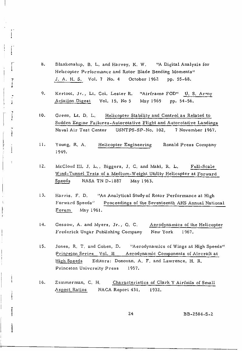
W 8. Blankenship, B. L. and Harvey, K. W. "A Digital Analysis for
Helicopter Performance and Rotor Blade Bending Moments"
7 J. A. H. S. Vol. 7 No. 4 October 1962 pp. 55-68.A
9. Kertoot, Jr., Lt. Col. Lester R. "Airframe FOD" U. S. Army
Aviation Digest Vol. 15, No 5 May 1969 pp. 54-56.
10. Green, Lt. D. L. Helicopter Stability and Control as Related to
Sudden Engine Failures -Autorotative Flight and Autorotative Landingsj Naval Air Test Center USNTPS-SP-No. 102, 7 November 1967.
11. Young, R. A. Helicopter Engineering Ronald Press Company
1949.
12. McCloud l, J. L,, Biggers, J. C. and Maki, R. L. Full-Scale
Wind-Tunnel Tests of a Medium-Weight Utility Helicopter at Forward
Speeds NASA TN D-1887 May 1963.
13. Harris. F. D. "An Analytical Study of Rotor Performance at High
Forward Speeds" Proceedings of the Seventeenth AHS Annual National
Forum May 1961.
14. Gessow, A. and Myers, Jr., G. C. Aerodynamics of the Helicopter
Frederick Ungar Publishing Company New York 1967.
15. Jones, R. T. and Cohen, D. "Aerodynamics of Wings at High Speeds"
Princ-eton Series Vol. II Aerodynamic Components of Aircraft at
High Speeds Editors: Donovan, A. F. and Lawrence, H. R.
Princeton University Press 1957.
16. Zimmerman, C. H. Characteristics of Clark Y Airfoils of Small
Aspect Ratios NACA Report 431, 1932.
24 BB-2584-S-2
1

17. Abbott, I, H. and Von Doenhoff, A. E. Theory of Wing Sections
Dover Publications, Inc. New York 1958.
18. Foster, D. N. "Some Aspects of the RAE High-Lift Research
Programme" The Aeronautical Journal of the Royal Aeronautical
Society Vol. 73 June 1969 p. 541 - 546.
19. McRae, b. M. "The Aerodynamics of High-Lift Devices on
Conventional Aircraft" The Aeronautical Journal of the Royal
Aeronautical Society Vol. 73 june !969 p. 535- 541.
20. Helmbold, H. B. "Limitations of Circulation Lift" JAS Vol. '24
March 1957 pp. Z3'7 - 238.
Z1. Lockwood, V. E., Turner, T. R., and Riebe, J. M. Wind Tunnel
Investigation of Jet-Augmented Flaps on a Rectangu.Aar Wing to High
j Momentum Coefficients NACA TN 3865 December 1956.
22. Erickson, J. C. and Kaskel, A. L, Theoretical Solutions and
Numerical Results for Low-Aspect-Ratio Rectangular Jet-U'lap
Control Surfaces Therm Advanced Research, Inc. TAR-TR 6603
December 1966.
23. Robinson, F., Batra, N. N., Duhon, J. M. and Lynn, R. R.
"Tail Rotor Design Part I - Aerodynamics" AHS 25th Annual
National Forum Proceedings May 1969.
24. Balke, R. W., Bennett, R. L,, Gaffey, T. M., and Lynn, R. R.
"Tail Rotor Design Part 2 - Structural Dynamics" AHS 25th Annual
National Forum Proceedings May 1969.
25. Glauert, H. Theoretical Relationships for an Aerofoil with Hinged
Flap British ARC, R & M No. 1095 1927.
25 BB-2584-S-2

APPENDIX A
Power Required For a Rotor
A relatively simple power-required equation for a general
helicopter configuration is given in Reference 11 as
F P required : P induced -t P profile + P parasite
2W C a -V3 ( 1+3 A-i V)
2 (V2 Z+') '1 + 8 V 2
where the variables have been defined in Section 2. 2. Let Vo Ithen Equation (A-1) reduces to dimensionless form
.vo- ,l,,,. " - 5,. 2,) -.)2 16 V1 Ve If V" (A -Z)
To find the speed (V/V 0) .at which the power required for flight is a minimum,
we differentiate Equation (A-2) with respect to (V/Vo) and set the
derivative equal to zero. A second differentiation has been performed and
it was determined that the resultant velocity is indeed a minimum. The
equation for the forward speed at minimum power then becomes:
~ 2V., ( ) , +
S3v." ( 3 __
+ -c V- ( V) 61 i'CL' Vo 4 9 y., , .
V. 0
26 BB-2584-S-Z
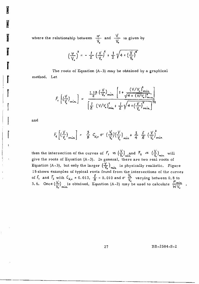
where the relationship between and 2 is given byVo V.
0C 4
21 ((V.)-VI
The roots of Equation (A-3) may be obtained by a graphical
[ method. Let
V V.[ v/V.) 4+ J +4 + - 1
and
V. ~ ~ ~ ~ L3 V.4 V,,f
then the intersection of the curves of F, vs (- L)and F2 Vs will
give the roots of Equation (A-3). In general, there are two real roots of
Equation (A-3), but only the larger (-). is physically realistic. Figure
15 shows examples of typical roots found from the intersections of the curves
of F, and F, with Cto = 0.013, -L= 0.010 and 0- a varying between 0.8 to
3. 6. Once ( is obtained, Equation (A-2) may be used to calculate IW V"
27 BB-2584-S-Z

[ APPENDIX B
v- Lift Coefficient for Finned EllipseI
The lift coefficient for a finned ellipse may be obtained by using
conformal mapping. The flow over a finned ellipse in the physical plane is
translormed to the equivalent flow over a flat plate in a transformed plane.
The lift coefficient for a flat plate at an angle of attack is well known. The
lift coefficient for the finned ellipse can then be computed through the
appropriate transformations.
The transformations proceed through several conformal mappings
as follows:
- LRJ ,-*. 2 - +J
.2IPLANE
I 8 BB--584-S-
Z 8 BB-Z584-S-2

We first transform the finned ellipse to the finned circle through=- ,.+ , with *- a-b~b
w = 4. The points -2, and 1. are transformed to-Yw and M2 respectively. The relationships between them are
and
a.+b
The radius of the circle is - . Then, the finned circle is transformed
to a flat plate by . 3 Z + . The points - 11 and n are the corresponding
points of-'fL, and m.
Now we can calculate the lift for a flat plate. The lift coefficient
for a flat plate at an angle of attack, ax is given by
where
d n, + "12
To find the lift coefficient of the finned ellipse it is necessary to transform
the chord of flat plate, d , back to the physical plane. Hence, we have
L= L3L 3
YrIf J-1- V a V C +
where n, and YL, are related to , and 1 through
"n'L MIM a
29Y-8 2
29 BB-Z584-S-Z

APPENDIX C
Flapped Fuselage
Generally, the tail boom of the helicopter has either a circular
or an elliptical shape. The concept of a mechanical flap may be applied to
generate high lift. In Appendix B, the lift coefficient for an ellipse with fin
4 has been calculated. Here we are going to illustrate the inverse procedure
and use the same mapping technique to determine the shape of the mechanical
flap. A flat plate with deflected straight flap is considered in the transformed
plane and we wish to caiculate the length and deflection angle of the corre-
sponding straight flap in the physical plane.
Let the mapping from the Z1- plane to the 7-,- plane be
R
or
.3 5 +2 +j/7 - 4R "
If this equation is split into real and imaginary parts, we obtain
V2
+ X -4(')- 4XC O2 - 42Rjzp, ( )T k 2
Y., 5 ( - ) - ) -4R +-,+X ' -(e - - )R2 2
S30 BB-Z584-S-2
I

where and R (2-) Hence, if 7' and are given
in the transformed plane, I., and 4, can be calculated and plotted in the
r physical plane.
Two special cases have been carried out for illustration. Here
C. is chosen as a unit length, and all length scales are nondimensionalized
by 0. . One case is for a flat plate of chord length4R= 2. 30 (thi- corresponds
to an ellipse in physical plane with a = 1.0, b = 1.15), flap length NA= 1.0
and deflection angle 93 = 60 degrees. The flap length in the physical plane is
La = 1. 09 and the deflection angle is 9, = 56 degrees, approximately
(Figure 16 ). Another case is a flat plate of chord length 4R= 4 (this
corresponds to a circle in the physical plane with , = b = 1. 0), flap length
Na .0 and 9 = 60 degrees. Then the flap length in the physical plane is
LZ= Z. 58 and the deflection angle is 9,= 37 degrees, approximately (Figure
17 ). Existing results for the lift of a flat plate with deflected flap
(Reference 25) could be used to calculate the lift on the flapped fuselage
cross -section.
31 BB-2584-S-2

ANTI-TIRQUE MOMENT REQUIRED, FLIGHT TE0iS- - -, AHTI-"CRQUE MOMENT REQUIRED, THEORY-- ANTI-.TOR QUE MOMENT AVAILABLE FROM
AEPJDYNAMIC SURFACES WITH GIVEN CL' lt' St
CLjtSt/RA 0.02426 0.0123 0.00885
12000/* I
I j/
r !
10000.
//
2000 do II000 10 2000I
iII
I 1I;,'-II
I t /s
I /I I i
0 / / //I /
/ I /I / sS
/ / /
I // s
60 s / ,1
/3 / /2000/ /
, -/
SFigure: NITRU MOMENT AVAILABLE FROM AERODYNAMIC SURFACES
I 6550 LB GROSS WEIGHT, 314 RPM
32 13B-2584-S-2
I

r
3.6 -...................... ... ... ....... . ............................. -.. ..
It
3,6 ................... . .. .. .. ... .................. .... ...........
a '
.2 .------- - --....... ........ ......... ......... ... ..... t... 0065. -------.
: og
. - 0 0a- - . . a
a.0 *- . . . .
a a
C a a
~E
0.0060
2 ............................ ... ...... ..
................ ... ........ ........... . ....... .. ... .- .o. oo. o .........
.0 ..... 2 .......... 4-..
.. a~o ......a aF 2 a a F aO
S CaN 2R8 COEFFICIEa, . . o SO L TIP... ........D I AT F A P AE ,, A
3 a a a a a * a
a a a . . . . . . . .
0 0
(Cd ,o/O.O13)GVt/vo
Figure 2 FLIGHT VELOCITY FOR MINIMUM POWER, Vrnin, AS A FUNCTION OF
SECTIONAL DRAG COEFFICIENT, CdI, o, SOLIDITY, o, TiP SPEED, Vij,
AND EQUIVALENT FLAT PLATE AREA RATIO, f/A
33 BB-2584-S-2

III
1. 6 ...................- ............ ............................. , -------. r ......... I11.6 Il* '
.. . . .. . . . . . .. . . . . . . . . . . . ..... . ... .. .
Vt/V o = 30 25 i 20l ......... ... . . ..... .'- ----------.... ......... ................. ........1.2 .......... .......... .... .......A......- ....... ...... ...... -
1.2 .. .. .. . ... . . . .
I. /
0.82 ......... 4....... ...... ; . 1.
0 1
i/. f/A'6,"
-- 0.10.1. ................ .... ... ......... - 0.08
0 . ........... .. . .. . . . .... ......... € - ......... ... ...... .........
; f/
(I 0.1200.6.1
0 .0
(Cd,o/O.O13)crvt/vo
Figure 3 INIUM POWER, Pmn AS A FUNCTION OF SECTIONAL DRAG COEFFICIENT,
,d,o, SOLIDITY, 0, TIP SPEED, Vt, AND EQUIVALENT FLAT PLATE AREA, f/A
34 BB-2584-S-2

Ir
. 25
a ................... . ---- ......... ----- a .. .................. ........ ..
* a a a a - a a oa a a , a a a* a a a a a a a
.........-- , . .. . . . . .. .. .. . ........ ......... .. .. ....... ,........ , .... .. ,
.. . . .. . . . -- - - - -- - - - .. .. . .. . ........
a a a a a a ,
.8 ..-.------- . .. ................................................................ ..--..........
a a a a a a a a,a a a a , a ,
........d".......t" .... "' ..... ........ •......... -- .......... --- ....... -*..... .........
* a a a a a
=30:,0 .25 . . a
0 6 ......... ',........... ..... .. a. . . . . . . . . . . . . . . . -. . . . ., . . . . . . .
.... .. . .. -, -- -- - - - - - -
.....* aaa " * . . . . . . . . . . . . . . . . . . . . . . . . . . . .
02.8 3.0 '3.2 3.4 3.6
VminlVo
Figure 4 ANTI-TORQUE PERFORMANCE OF A 2%o TAIL -POWER, P2, AS A FUNCTION
OF FLIGHT VELOCITY FOR MINIMUM POWER, Vmi n , AND TiP SPEED, Vt
35 BB-2584-S-Z

w LLw
I-L
LL
ICI
36 6 o W L-S

13ft2 n
a) ORIGINAL OH-6A HELICOPTER
St S +,ASt 5.65 + 13.0 =18.65 ft 2 3.LIA/100
b) MODIFIED OH-6A WITH POSSIBLE SURFACES ADDED ON THE BODY
St = 3 to + A___ t + :r 5.65 + 3- 8.65 1.6A/100
c) MODIFIED OH-6A WITH POSSIBLE SURFACES ADDED ON THE TAIL
Figure 6. POSSIBLE OH-GA MODIFICATIONS
37 BB-2584-S-2

-22 ft
A =1520.5 ft 2
S =8 ft 2 :-O.5A/I00a) ORI GINAL IJH-2 HELICOPER 0o
St=St +ASt :t8 + 70 ft 2 78ft 2 ~ 5A/100
b) MODIFIED UH-2W ITH POSSIBLE SURFACES ADDED ON THE BODY
St st + Ast 8 + 211 f t 2 :z32 f t 2~ 2. 1A/ 100
c) MODIFIED UH-2 WITH POSSIBLE SURFACES ADDED ON THE TAIL
Figure 7. POSSIBLE UH-2 MODIFICATIONS
38 BB-Z584-S-Z

-31 f
IA 3019 f t'
a) ORIGINAL SH-3D) HELICOPTER 0
1 -31 ft
St 741 ft 2 2.0I/100
b) MODIFIED SH-3D) WITH POSSIBLE SURFACES ON THE BODY
31 fl
ST 52.5 1.7A/100
c) MODIFIED SH-3D) WITH POSSIBLE SURFACES ADDED ON THE TAIL
Figure 8. POSSIBLE SH-3D) MODIFICATIONS
39 BB-2584-S-2

361f
A =4071.5
a) ORIGINAL CH-53A HELICOPTER St 0 50 ft 2 ) .2A/100
*St St 0 +Ast 50 + 60 110 ft2 ~ 2,7A/ 100
b) MODIFIED CH-53A WITH POSSIBLE SURFACES ADDED ON THE BODY
StSt0 + ASt 50 + 40 90 f t2 =2. 2A/ 100
c) MODIFIED CH-53A WITH POSSIBLE SURFACES ADDED ON THE TAIL
* I Figure 9. POSSIBLE CH-53A MODIFICATIONS
I40 BB-2584-S-2

2 BLADES
A =1520.5 ft2
a) ORIGINAL UHi-C HELICOPTER t0=1f2 0.3/o
St t +As + 15- 26 f 2 I.7A/IO qb) MODIFIED UHl-IC WITH POSSIBLE SURFACES ADDED ON THE BODY
t 5 t +,a t + 1 2 ft 1. 7A/ 100
c) MODIFIED UH-IC WITH POSSIBLE SURFACES ADDED ON THE TAIL
Figure 10. POSSIBLE tif-IC MODIFICATIONS
41 BB-2584S-
2

Ul - wL
7 LCo LL.-i-L- - -
qm LL - C
J-rnrLID P) T m < LL- 00 oz0
-.- ~C -< - -- 0'
I U- WL j<
;-I--
u-I
Go ~ ~ ~ =r ci
0) C)toC
C; C..
42 BB-584-S-

I
I
3.2
2.8
2.0- 6, deg
ii-Z 1.2[. ------ -- -w 15
.. 0.8 -- - - -
0.
Uji
0 -ido' --- \
-P
-0.4__Z
-0 .8 - -.
°12 Iii/
-24 -16 -8 0 8 16 24 32SECTION ANGLE OF ATTACK, deg
Figure 12. AERODYNAMIC CHARACTERISTICS OF THE NACA 66(215)-216 AIRFOILSECTION WITH 0.20c SEALED PLAIN FLAP (REFERENCE 17)
43 BB-2584-S.2

w -j
0.8
SYBO 0.6TINMOE
0.2 - HOY ASETRTI
01. .4060. .
FLP U SYRDLMIOL PEOCDITIOF MODELP
Figue 13 THERETIAL AD HEORYA APET-SRATI FT7.
FACORSFORTWHEOSREASPEC RAIO8 .3
TAPE RATIO 0.35

aRA c 3V W -
NcIK
ES R
RE~RE I
Figure 14~. A SCHEMATIC DIAGRAM OF A UH-1A PROFILE WITHTHE MORE IMPORTANT DIMENSIONS LABELED
45 BB-2584-S-2

I
0 .6 -- ---- -- --- ---- ------- -
--' -t -0 .6 -- -- ---.... " . ... .... .. ... ................. .... ......ft
0.....................---..
Ii
O ~ ~ ~ ~ - - ---.. .. . . ...... -- ... ......... ............ .."................... .......
?F
1. :.FV/Vo)min 1
0 .2 .. ....... ---..... ....... -- ...--'--- . . . .. . ---------- .... .. ---------- .. ...............
.3 0
2.5-* . ff2.0
:= O i .... .... . ... .. ........... ." ..... . . .... ...
0 .... ... .. ............. . ... -- -- -- -- ---- -- -- -- -
0.08 ........... . I
. ... .......
, O .OF. .........---.... ............. .. ......... : ........... --. .. .. ...------... .. .. ..
0.0223 5
LI..
F2[(V/V)omnl
T 01...............
: 0.02 23 4 5
Figure 15. THE INTERSECTION OF THE CURVES OF F1 AND F2 WITH Cd, 0.013,
f/A = 0.01, and o-(VtIVo) VARYING BETWEEN 0.8 AND 3.6
46 BB-Z584-S-2

....... ...........
. . . .. . . . . . . . . . . . ... . . ... .. .. .. .
.. .. . . .f. . . . . . . . . ......
CD.
U-
. . . . . ... .. . . ** 0
ce. . -
.. . .... ..
0-
I .
CCD
if ....... ....
.... . ..... .... .....
47~C CB.>4--

~. ........ ........ . . . . . .......... - ° ' ° ° ° ' "
"' . .•....... .. ..
... ... .. .. .. ... .. .. .... ... .......... .........
.. .. . . . . . . .. . ..
04 . .. ... .. .. ..
__,I, I 'I
............. ...........
.3_
....... ............... -------.. . ... . . ... -.......... . ., , ... . CI
: ;... . .. . . . .. .... . ..... .. .. ... ,, _
. I I * I I
' c . :... .. .• ... .. ......... . ...... L .. ......................... ....... . .........
. .. ..i. . .... ...... .......--- ...................................... L ......... , ..........
: LL.. . I . 4
. . . .. . . . . . . . . . . . . . . . . . . . . . . . . .
.. . . .. . . .. .. . . . .. . . .. . .. . . . . .
48 BB-584S-

?IA Unclassified
Security Classiflcatlon
DOCUMC-NT CONTROL DATA- R & DISOCUIlW casalstirat ol of title. body of abstact and Indezung olnotatin must be antered whwn the ovrall report Is fixassllted)
1. ORIGINAtNG ACTIVITY (Corporals uthor) -- . 4EPORT SCCUMITY CLASS,'ICATCON
Cornell Aeronautical Laboratory, Inc. UnclassifiedBuffalo, New York 14221 lb. aRo.,.
3. REPORT ITLE
THE FEASIBILITY AND USE OF ANTI-TORQUE SURFACES IMMERSEDIN HELICOPTER ROTOR DOWNWASH
4. DESCRIPTIVE NOTES (),pe of report and IncIL-ire datoe)
Technical Report Januarv 1 (68 - Decereih(-r I QhQ5. AUTHOR(S) (First name, mddle Initial, Iset name)
Chee Tung, John C. Erickson, Jr., and Frank A. DuWaldt4
6. REPORT DATE 741. TOTAL NO. OF PAGES J7b. NO. OF REF
February 1970 tSe. CONTRACT OR GRANT NO. 94. ORIGINATOR'S REPORT NUIM'ERMS
N00014-68-C-0241b. PROJECTNO. CAL No. BB-2584-S-2
NR 212-182C. 9b. OTHIER REPORT NOS) (Any other su-ibers that nay be asnseagd
this report)
d.
10. DISTRIBUTION STATEMENT
This document has been approved for publc 'elease and sale, its distritutionis unlimited.
1I. SUPPLEMENTARY NOTE 12. SPONSORING MILITARY ACTIVITY
Office of Naval ResearchAeronautics, Code 461Arlington, " irginia 22217
13. ASTRACT
An analytical investigation was made of the effectiveness of anti-torque aerodynamic surfaces immersed in helicopter rotor downwash. It isshown that additional vertical tail surface having areas equal to about two percentof the main rotor disk area could provide torque trim for speeds aboveabout 75 ft/sec for representative current vehicles.
/I
6o,,-va IO OMy USK. Unclassified
curity CJamaficatlon

UnclassifiedcSecurity ClassifiCsion--
14. LINK A LINK 8 LINK CKCV WORDS ROLE WT ROLE WT Rt) LE WT
HelicopterTail RotorAnti-Torque Devices
-i.. . , '- ... ...___ _ __ _ _ __ _ __ _ __ _ __ _ __ _ __ _ _
Unclassified
Secuity Clasmaflcation