an empirical model of rotorcrafy uav downwash for ... · an empirical model of rotorcraft uav...
TRANSCRIPT
1
An Empirical Model of Rotorcraft UAV Downwash Model
for Disturbance Localization and Avoidance
Derrick Yeo1 , Elena Shrestha
2, Derek A. Paley
3
Department of Aerospace Engineering, University of Maryland, College Park, Maryland , 20742, U.S.A
and
Ella Atkins 4
Department of Aerospace Engineering, University of Michigan, Ann Arbor, Michigan, 48109, U.S.A
Proximity operations of small rotary wing air vehicles pose a unique challenge due to the downwash they
generate. These vertical flow disturbances may cause substantial and potentially hazardous flight disruption
to nearby vehicles. This paper presents a downwash detection and localization strategy intended for use on
small unmanned rotorcraft. A probabilistic framework estimates the position of neighboring rotorcraft
operating at a higher altitude by combining onboard velocity measurements with a reduced-order flow
model. A series of ground-based experiments that characterize the flow beneath a representative group of
small rotary wing vehicles are described. A custom pressure probe designed to be carried by small rotary
wing vehicles is mounted on an automated two-axis Cartesian carriage system, which enables accurate sensor
placement. Velocity measurements collected in a prescribed path are assimilated into an axis-symmetric
downwash model. Tests show that disturbances can be localized to the region directly beneath each vehicle
while the sensor is still approaching, demonstrating basic downwash detection and localization capabilities
for three different rotorcraft configurations.
Nomenclature
𝑢, 𝑣, 𝑤 = Velocity components, m/s
𝜌 = Air density, kg/𝑚3
𝜇 = Dynamic viscosity of air, kg/ms
𝜐 = Kinematic viscosity of air, m/𝑠2
𝛽 = External source location vector
𝑧(𝑡𝑘) = Flow measurement at time 𝑡𝑘, m/s
𝐴 = Posterior scaling coefficient
𝑟 = Radial distance from central axis, m
𝑈0 = Maximum profile velocity, m/s
𝐶 = Velocity profile scaling factor
I. Introduction
mall rotary-wing unmanned aircraft systems have recently seen widespread use throughout the public domain.
Conventional helicopter configurations have been in service for a number of years [1,2] whereas multi-rotors
have recently become synonymous with small unmanned aerial systems for recreational, research, and military
applications [3,4]. With an increasingly crowded airspace, small air vehicles must face a new set of challenges
associated with proximity flight. One specific challenge of rotary wing platforms is that their downwash can induce
significant flow-field disturbances for other vehicles operating nearby and at a lower altitude. With minimal air
traffic control regulations expected for small unmanned air vehicles (UAVs), onboard downwash detection could
provide a means of disturbance avoidance on vehicles that have limited sensor capabilities.
1 Research Associate, Aerospace Engineering Department, [email protected] AIAA Member. 2 Graduate Research Assistant, Aerospace Engineering Department, [email protected] AIAA Student Member. 3 Willis H. Young Jr. Associate Professor, Aerospace Engineering Department and Institute for Systems Research,
[email protected] AIAA Senior Member. 4 Associate Professor, Aerospace Engineering Department, [email protected] AIAA Associate Fellow
S
Dow
nloa
ded
by D
erek
Pal
ey o
n Ja
nuar
y 8,
201
5 | h
ttp://
arc.
aiaa
.org
| D
OI:
10.
2514
/6.2
015-
1685
AIAA Atmospheric Flight Mechanics Conference
5-9 January 2015, Kissimmee, Florida
AIAA 2015-1685
Copyright © 2015 by Derrick W. Yeo, Elena Shrestha, and Derek A. Paley. Published by the American Institute of Aeronautics and Astronautics, Inc., with permission.
AIAA SciTech

2
This paper describes a downwash localization strategy that uses onboard air velocity measurements to provide
disturbance detection and position estimates. Recursive Bayesian estimation is used in conjunction with a reduced-
order flow model of rotorcraft downwash to assimilate vertical velocity component measurements and to generate
probable locations of a nearby disturbance source. The approach is experimentally evaluated for three small UAVs
with different rotor configurations (Fig. 1) using an automated two-axis Cartesian carriage system equipped with a
custom pressure probe. The contributions of this research are (1) generalized downwash model for small rotorcraft
UAVs developed for real-time estimation with limited onboard instrumentation; and (2) set of downwash surveys of
three representative small rotorcraft UAV configurations. A companion paper illustrates the use of the downwash
model for path planning [5].
The rest of this paper is organized as follows. Section II provides a background on small rotorcraft downwash
characterization. Section III presents a probabilistic framework for sensing and avoiding downwash along with a
reduced-order approach to downwash modelling. Section IV describes experiments that characterize the downwash
beneath three different rotorcraft UAV configurations, which provide realistic flow fields to evaluate the localization
strategy. Section V presents experimental data and Section VI documents localization results of the proposed
estimation framework. Section VII summarizes the paper and describes ongoing work.
(a) Quadrotor configuration (b) Single main rotor configuration (c) Twin cycloidal rotor configuration
Figure 1: Small rotorcraft configurations currently in service at the University of Maryland
II. Background
Aerodynamic models that have previously been used to model conventional rotorcraft downwash [6] range from
simple momentum theory to CFD models. Recent efforts in understanding rotor downwash effects on the
environment have been motivated by desert environments commonly found in contemporary military operations [7,
8,9]. For example, Ghosh et al. [10] employed a CFD model to study the effect of rotor configuration on brownout,
including a quadrotor configuration.
The more relevant field of small UAVs has also seen theoretical and experimental efforts. For example,
Shkarayez et al. [11] conducted a series of wind tunnel tests that measured the contribution of propeller wash on the
aerodynamic characteristics of a tail-sitter VTOL (vertical takeoff and landing) UAV concept, using force-balance
instrumentation and hot-wire anemometry. Stone [12] modeled wing-propeller interaction on a tail-sitter UAV using
a low-order fixed-wake panel method. These results have focused on wing-in-slipstream interactions, which are a
secondary concern when attempting to detect and avoid a region of potentially hazardous downwash.
A low-order vortex model was employed by DeVries and Paley [13] to develop a sensing and estimation strategy
to detect the wake of a refueling aircraft, providing a fixed-wing counterpart to the research proposed in this paper.
Focusing on fundamental downwash characteristics, Khan et al. [14] developed a semi-empirical model that
describes the wash generated by a single propeller. While directly relevant to small scale UAVs, the model is
designed to simulate a single rotor using a set of known parameters, making it less suitable for a general, real-time
estimation approach which must assume minimal prior knowledge of the flow field. Furthermore, it also does not
account for the interaction that can be expected beneath a quadrotor. Yeo et al. [5] demonstrated the use of an even
simpler model in conjunction with a Bayesian estimation scheme and an on-board flow sensing package for
downwash disturbance on a small quadrotor UAV. Leese and Knight conducted a similar survey at full scale, using
arrays of anemometers [15] to study the downwash of seven different military helicopters in service with the United
States Army in 1974. A more recent test by Sjoholm et al. used a continuous-wave Doppler lidar to generate
turbulent near-ground flow fields under a hovering rescue helicopter [16]. These flow measurements were taken
near the ground. Small-scale experiments near the rotor have been conducted using hot-wire anemometry [17] and
particle image velocimetry [18] techniques, while a custom designed multi-hole probe by Zilliac 19] has also
Dow
nloa
ded
by D
erek
Pal
ey o
n Ja
nuar
y 8,
201
5 | h
ttp://
arc.
aiaa
.org
| D
OI:
10.
2514
/6.2
015-
1685

3
successfully provided fine-scale wake-flow information [20]. Due to its portability and application to small scale
UAVs, a probe-based instrumentation scheme is used in this work. This paper describes the development of this
reduced-order approach to downwash modelling for real-time estimation onboard small rotorcraft UAVs. It
documents a series of ground-based tests designed to evaluate its viability as a generalized model. A series of
experimental surveys of the downwash generated by small rotary wing vehicles is included. An automated
instrumentation positioning system has been built to take measurements along prescribed paths and the results from
these surveys are used to evaluate the real-time estimation strategy.
III. Localizing the Source of Rotorcraft Downwash
This section presents a recursive estimation strategy that can detect downwash caused by a rotary-wing vehicle
and generate estimates of its overhead location. This approach requires a reduced-order downwash model that is
broadly applicable to a range of small rotary UAV configurations. It is theorized that fundamental flow physics
result in common downwash features even for different rotorcraft configurations that can be estimated inflight using
basic flow instrumentation. This section describes how insight from simple experimental data guided the derivation
of simplified flow equations that are used within a Bayesian estimation scheme.
A: Reduced-order modelling
A flow-field model suitable for estimation needs to adequately capture key characteristics of rotorcraft
downwash that is independent of configuration. In addition, it needs to function for wide variety of situations with
little prior information. As all rotorcraft generate lift through momentum transfer with the air, this suggests a degree
of self-similarity in their turbulent downwash that will be amenable to a generalized physical model. A two-bladed
fan was chosen as the simplest representation of the downwash from a hovering rotorcraft. Axial velocity
measurements taken within the zone of flow establishment were considered. Three key characteristics can be
identified. The measured velocity near the center of the fan is higher than at the edge. Secondly, approximately
exponential decay in velocity away from the centerline is also apparent. (This reflects the fundamental property of
momentum conservation in a fluid flow.) Lastly, there are two velocity peaks surrounding the fan hub which is a
characteristic of the velocity distribution before the slipstream flow is fully established.
These observations are qualitatively consistent with propeller slipstream measurements published in literature
[14]. Within the zone of flow establishment, flow features near the centerline can be thought of as vehicle specific.
Far below the vehicle and near the slipstream boundary, it is expected that the effects of diffusion will dominate.
Based on this intuition, a theoretical middle ground between a purely physics-based approach and a first-order
model is obtained through simplification of the Navier-Stokes equation. Consider a two-dimensional flow field
where a rotor generates thrust by accelerating flow in the z direction. Velocity components w and v lie along the z
and y coordinates. The momentum equation in the z direction is [21]
𝜕𝑤
𝜕𝑡+ 𝑤
𝜕𝑤
𝜕𝑧+ 𝑣
𝜕𝑤
𝜕𝑦 = 𝑔𝑧 −
1
𝜌
𝜕𝑝
𝜕𝑧+
𝜇
𝜌 (
𝜕2𝑤
𝜕𝑧2 +𝜕2𝑤
𝜕𝑦2 )
(1)
where 𝜌 is air density, 𝜇 is the dynamic viscosity of air, and 𝑔𝑧 represents body forces due to effects such as
buoyancy.
The following set of assumptions are applied: (1) the mean flow-field is unchanging, so 𝜕𝑤
𝜕𝑡 is zero; although
rotorwash is highly turbulent, we consider the mean flow-field velocity generated by a hovering rotorcraft to be
steady for these purposes. (2) Cross-stream flow is small compared to the downstream flow; this assumption is
based on the intuition that even with the helical structure common to rotor-driven flows, the cross-stream velocity
plays a secondary role in thrust generation. Only the thrust-aligned velocity component is considered and thus 𝜕𝑤
𝜕𝑦 is
neglected (3) At each downstream location, the stream-wise variation in 𝑤 is considered to be small compared to
cross-stream changes; hence 𝜕2𝑤
𝜕𝑧2 is ignored. (4) Buoyancy and external pressure gradients are considered to be
absent, hence 𝑔𝑧 and 𝜕𝑝
𝜕𝑧 are neglected. These assumptions result in
𝑤𝜕𝑤
𝜕𝑥=
𝜇
𝜌(
𝜕2𝑤
𝜕𝑦2 )
(2)
Dow
nloa
ded
by D
erek
Pal
ey o
n Ja
nuar
y 8,
201
5 | h
ttp://
arc.
aiaa
.org
| D
OI:
10.
2514
/6.2
015-
1685
4
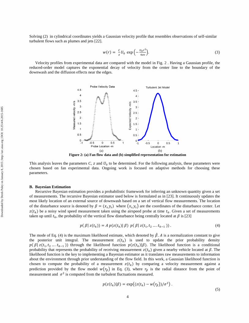
Solving (2) in cylindrical coordinates yields a Gaussian velocity profile that resembles observations of self-similar
turbulent flows such as plumes and jets [22].
𝑤(𝑟) = 𝐶
𝑧𝑈0 exp (−
𝑈0𝑟2
4𝑧𝜐). (3)
Velocity profiles from experimental data are compared with the model in Fig. 2 . Having a Gaussian profile, the
reduced-order model captures the exponential decay of velocity from the center line to the boundary of the
downwash and the diffusion effects near the edges.
(a) (b)
Figure 2: (a) Fan flow data and (b) simplified representation for estimation
This analysis leaves the parameters C, 𝑧 and 𝑈0 to be determined. For the following analysis, these parameters were
chosen based on fan experimental data. Ongoing work is focused on adaptive methods for choosing these
parameters.
B. Bayesian Estimation
Recursive Bayesian estimation provides a probabilistic framework for inferring an unknown quantity given a set
of measurements. The recursive Bayesian estimator used below is formulated as in [23]. It continuously updates the
most likely location of an external source of downwash based on a set of vertical flow measurements. The location
of the disturbance source is denoted by 𝛽 = (𝑥𝑠,𝑦𝑠) where (𝑥𝑠,𝑦𝑠) are the coordinates of the disturbance center. Let
𝑧(𝑡𝑘) be a noisy wind speed measurement taken using the airspeed probe at time 𝑡𝑘. Given a set of measurements
taken up until 𝑡𝑘, the probability of the vertical flow disturbance being centrally located at 𝛽 is [23]
𝑝( 𝛽| 𝑧(𝑡𝑘)) = 𝐴 𝑝(𝑧(𝑡𝑘)| 𝛽) 𝑝( 𝛽| 𝑧(𝑡1, 𝑡2 … . 𝑡𝑘−1 )) . (4)
The mode of Eq. (4) is the maximum likelihood estimate, which denoted by �̂�. 𝐴 is a normalization constant to give
the posterior unit integral. The measurement 𝑧(𝑡𝑘) is used to update the prior probability density
𝑝( 𝛽| 𝑧(𝑡1, 𝑡2 … . 𝑡𝑘−1 )) through the likelihood function 𝑝(𝑧(𝑡𝑘)|𝛽). The likelihood function is a conditional
probability that represents the probability of receiving measurement 𝑧(𝑡𝑘) given a nearby vehicle located at 𝛽. The
likelihood function is the key to implementing a Bayesian estimator as it translates raw measurements to information
about the environment through prior understanding of the flow field. In this work, a Gaussian likelihood function is
chosen to compute the probability of a measurement 𝑧(𝑡𝑘) by comparing a velocity measurement against a
prediction provided by the flow model 𝑤(𝑟𝛽) in Eq. (3), where 𝑟𝛽 is the radial distance from the point of
measurement and 𝜎2 is computed from the turbulent fluctuations measured.
𝑝(𝑧(𝑡𝑘)|𝛽) = exp ((𝑧(𝑡𝑘) − 𝑤(𝑟𝛽))/𝜎2) .
(5)
0 200 400 600 8000
0.5
1
1.5
2
2.5
3
3.5
4
4.5Piece-wise Linear Model
Location -mm
Expecte
d V
elo
city -
m/s
-1 -0.5 0 0.5 10
0.5
1
1.5
2
2.5
3
3.5
4
4.5Probe Velocity Data
Probe Location -m
Measure
d v
elo
city -
m/s
-1 -0.5 0 0.5 10
0.5
1
1.5
2
2.5
3
3.5
4
4.5Turbulent Jet Model
Location -m
Expecte
d V
elo
city -
m/s
Dow
nloa
ded
by D
erek
Pal
ey o
n Ja
nuar
y 8,
201
5 | h
ttp://
arc.
aiaa
.org
| D
OI:
10.
2514
/6.2
015-
1685

5
C. Two-dimensional localization example
The localization of a modelled downwash source was performed to validate the Bayesian estimation approach.
The localization scheme is used with a single flow sensor approaching an idealized downwash source. The reduced-
order model is used to generate both the estimated flow field and the sequence of sensor measurements. Uncertainty
is introduced through mismatches in model parameters and through process noise that represents velocity
fluctuations present in actual measurements. Results from four time steps are shown Fig. 4. The contour-maps depict
the posterior distribution of the location of the disturbance. Red indicates high probability whereas blue indicates
low probability. Red asterisks denote the measurement location. Fig. 4(d) also shows the path taken by the probe as
it approaches the disturbance.
Figure 3: Simulated localization results with numerically generated flow measurements
With no significant flow velocity measured initially, the estimation scheme reports a low probability of any
downwash source within some radial distance of the sensor that corresponds to the measured turbulence level. As
successive measurements are assimilated, arcs of high probability are computed, resulting in a final estimate that is
close to the center of the idealized downwash. With a single sensor, the path taken by the sensor is critical as it is the
only means to spatially distributing the measurements. For consistency, the same trajectory taken in this example is
replicated using an automated instrumentation carriage system during experiments with actual downwash sources.
These tests are described in the following sections.
Dow
nloa
ded
by D
erek
Pal
ey o
n Ja
nuar
y 8,
201
5 | h
ttp://
arc.
aiaa
.org
| D
OI:
10.
2514
/6.2
015-
1685

6
IV. Experimental Setup
To evaluate the applicability of the estimation strategy to a range of small rotorcraft UAVs, a series of ground-
based tests were designed to simulate flight trajectories of a sensor within the downwash of different rotorcraft
configurations. The vehicles were suspended within the Collective Dynamics and Control Laboratory motion-
capture facility to generate realistic flow fields. This section introduces the automated measurement system
developed for these tests.
A. Automated instrumentation carriage system
A two-axis translating rail and carriage system was developed and built to support the flow measurements
required for this work. A sliding carriage is driven over a guide rail with a servo-motor and drive wheel, providing
translation in the inertial x-direction. The guide rail is itself propelled in the y-direction through a servo-motor
powered winch and pulley system. The carriage system is controlled using position feedback from the motion-
capture camera system. In addition to providing repeatable sensor positioning within a volume of interest, this
system allows a sensor payload to be guided through prescribed trajectories in a plane. Experiments are coordinated
by a desktop computer that communicates with the motion capture system, drive actuators, and flow
instrumentation. A picture of the test setup and a breakdown of key components are shown in Fig. 4.
(a) (b)
Figure 4: Automated instrumentation carriage and experimental system overview.
B. Custom velocity probe
For this work, a pressure-based velocity probe [24] was mounted face- up and used to take flow velocity
measurements within the downwash regions. Having been designed to be carried on a small UAV, it represents the
sensor capabilities that can be expected of a small rotary wing vehicle [5]. While the probe can provide flow
angularity information, only vertical velocity measurements are considered in this work. The probe and the
mounting system are shown in Fig. 5.
(a) (b)
Figure 5: Multi-hole probe stand and port configuration [24]
Dow
nloa
ded
by D
erek
Pal
ey o
n Ja
nuar
y 8,
201
5 | h
ttp://
arc.
aiaa
.org
| D
OI:
10.
2514
/6.2
015-
1685

7
A MK20DX256VLH7 ARM cortex M4 microprocessor was used for data acquisition, storage and transmission.
Pressure measurements across the ports are taken using Honeywell HSCDRRN series differential pressure sensors at
1kHz for 5 seconds with 13bit Analog-to-digital-convertor resolution.
V. Small UAV downwash measurements
Downwash measurements from beneath multiple small rotorcraft UAVs were sought to experimentally evaluate
the proposed estimation strategy. This section presents velocity measurements from a series of flow surveys
conducted on a two-bladed propeller and three different rotary UAV configurations. In each case, the outline of the
rotors are super-imposed over the velocity contours in black and green lines. The axes are aligned with body frame,
providing a top-down view of the vehicle as it faces the right side of the page. The avionics package on each test
vehicle is augmented with a Hall-effect sensor and embedded electronics to govern rotor RPM.
A. Isolated propeller
A two bladed, 13x6 propeller was used to provide a simple, axisymmetric flow field. Since the flow generated
would be similar to the modelled downwash, this reference case would provide insight on the effects of flow
turbulence on the estimation strategy. The propeller operated at 3500 RPM, corresponding to a tip Reynolds number
of approximately 70,000. The velocity contours at four diameters downstream are shown in Fig. 6.
Figure 6: Isolated propeller test setup and velocity data at 4 diameters downstream
B. Single main rotor
The conventional configuration uses a single main rotor and a tail rotor for anti-torque. For this experiment, a
Dynam 250 two-bladed radio control helicopter with a 500 mm rotor diameter was used to generate the flow field.
The swashplate and tail rotor pitch control linkages were adjusted for a hover condition and secured using vibration-
isolation rubber. The velocity profiles in Fig. 7 were taken at 3.5 diameters beneath the vehicle. It shows a largely
axisymmetric distribution that is expected from a single main rotor.
Figure 7: Conventional helicopter velocity distribution at 3.5 rotor diameters
Dow
nloa
ded
by D
erek
Pal
ey o
n Ja
nuar
y 8,
201
5 | h
ttp://
arc.
aiaa
.org
| D
OI:
10.
2514
/6.2
015-
1685

8
C. Quadrotor
By using two pairs of counter-rotating propellers, the quadrotor helicopter configuration allows for a
mechanically simple rotorcraft design with few moving parts. The vehicle used for these tests is a DJI Phantom, a
small quadrotor that uses 8-inch diameter propellers. The velocity distributions at 7 rotor diameters below the
vehicle are shown in Fig. 8.
Figure 8: Quadrotor vertical velocity profiles at 7 rotor diameters
It can be observed that within 5 rotor diameters, the vertical velocity had an approximately elliptical Gaussian
distribution due to interaction between the wash of the two counter-rotating pairs of rotors. Each counter-rotating
pair generates slipstreams that reinforce or weaken each other as they meet on along a plane of symmetry. With the
Phantom’s rotor configuration, the slipstreams reinforce each other along the plane of symmetry that extends out the
sides of the vehicle, while mutually weakening along the plane that extends through the front and back of the
vehicle. This effect is also observed with tandem and tilt-rotor helicopters [25]. With a single velocity peak, this
profile is relatively simple but only approximately possesses rotational symmetry about a central axis.
D. Cycloidal rotor
Unlike most rotary wing vehicles, the UMD twin cyclocopter uses a pair of cycloidal rotors to generate lift and
thrust while a third conventional propeller generates both lift and anti-torque in the pitch axis [26,27]. The 6 inch
diameter cycloidal rotors accelerate flow downwards and towards the front of the vehicle (towards the propeller
system) due to their rotation. The torque generated by the horizontal propeller is counteracted through an
asymmetric thrust vector setting on the cycloidal rotors. This generates a vertical velocity distribution that is
asymmetric front-to-back and side-to-side as shown in Fig. 9.
Figure 9: Cyclocopter velocity profiles at 8 rotor diameters
Dow
nloa
ded
by D
erek
Pal
ey o
n Ja
nuar
y 8,
201
5 | h
ttp://
arc.
aiaa
.org
| D
OI:
10.
2514
/6.2
015-
1685

9
VI. Localization Results
The experimental data from the downwash surveys was used to evaluate the estimation strategy in different
realistic flow fields. These results are summarized in the following subsections. In each case, the probability density
at the final time step is plotted with the location of the mode �̂� marked by a green asterisk. The sequence of sensor
measurements is marked with red asterisks, and the footprint of the vehicle is outlined in green. As in Section V,
figure axes are aligned with the body frame of the test article, showing a view of the vehicle from the top with the
nose of the vehicle facing the right side. The flow model parameters and sequence of sensor positions used in the
numerical simulation are replicated in each scenario. The intent is to gain insight into how much prior information is
required by the estimation scheme to accommodate different flow fields and vehicle configurations and to motivate
further model development and evaluation methodologies.
A. Single Propeller Slipstream
The estimation framework was first tested within the flow generated by a single propeller. Although the isolated
propeller is axisymmetric, the sensor path was recreated to approach the propeller from the front and aft as a first-
order verification of the system. These results are shown in Fig. 10(a) and Fig. 10(b) respectively. It can be noted
that variations in measured velocity and varying levels of turbulence between both sets of measurements result in a
slightly different final location estimates. On both paths, the central location of the propeller is localized to within
15% of propeller diameter.
(a) (b)
Figure 10: Isolated propeller estimation results
B. Conventional Single-Main-Rotor Helicopter
The flow field measured under the conventional helicopter in hover is similar to that generated by the single
propeller. While the tail-rotor introduces a subtle left-to-right asymmetry on the downwash, this effect is not
expected to significantly influence the estimation scheme. The sensor path used in the numerical simulation included
both frontal and rearward vehicle approach in order to gauge the effect of the tail rotor in these tests. As expected,
the performance of the localization scheme under a conventional helicopter is similar to that observed under a single
propeller. For both trajectories, the center of the vehicle is localized to within 15% of main rotor diameter. The
results are shown in Fig.11.
Dow
nloa
ded
by D
erek
Pal
ey o
n Ja
nuar
y 8,
201
5 | h
ttp://
arc.
aiaa
.org
| D
OI:
10.
2514
/6.2
015-
1685

10
(a) (b)
Figure 11: Estimation results for single-main-rotor configuration
B. Quadrotor Helicopter
The elliptical velocity profiles beneath the quadrotor offers an additional level of complication in the estimation
scheme since the flow field is not axisymmetric. The velocity gradient recorded by a set of measurements depends
on the orientation of the quadrotor. Two sensor paths are chosen that approach the vehicle between both planes of
symmetry. Estimates were generated within 30% of vehicle length and the localization results are shown in Fig.12.
It is observed that these factors resulted in reduced localization accuracy compared to the conventional helicopter
downwash case.
(a) (b)
Figure 12: Quadrotor helicopter estimation results, front and side approaches
C: Cycloidal Rotor Vehicle
The flow-field of a hovering cyclocopter is more complicated than the previous configurations because of a
distinctive fore-aft geometric asymmetry from the twin cycloidal rotors and a horizontal anti-torque rotor. These
features are not represented in the flow model and may pose challenges to the estimation scheme. Four sensor paths
were taken. The first set approaches the front and rear of the vehicle, where the conventional propeller is located.
The second approaches the rear of the vehicle, where the cycloidal rotors and their unique velocity profiles are
encountered. These results are shown in Fig. 13(a) and Fig. 13(b), respectively.
Dow
nloa
ded
by D
erek
Pal
ey o
n Ja
nuar
y 8,
201
5 | h
ttp://
arc.
aiaa
.org
| D
OI:
10.
2514
/6.2
015-
1685

11
The experiment was repeated with the same basic path approaching the vehicle from the sides, where the
interaction between the cycloidal rotors and the horizontally mounted propeller create a profile expected to confound
the estimation scheme. These results are presented in Fig. 14.
(a) (b)
Figure 13: UMD twin cyclocopter localization results - fore/aft approaches
(a) (b)
Figure 14: UMD twin-cyclocopter localization results – flanking approaches
The frontal and rearward approaches generate estimates that barely lie beneath the hovering vehicle. Observe that
while the measurement paths from both directions generate feasible estimates, these flanking approaches have
greater estimation uncertainty indicated by large arcs of probability. In all four cases, the localization scheme
provides a final location estimate that is within the footprint of the vehicle, demonstrating a basic disturbance
avoidance capability despite the simple flow model. These results reinforce the intuition that the increasing velocity
gradients encountered on an approaching trajectory are a fundamental characteristic of any hovering rotorcraft and
provide sufficient information to support simple disturbance avoidance schemes.
D: Multi-Sensor Examples
Multiple spatially distributed measurements at each time step enhances the accuracy of flow-field information.
Two spatially distributed measurements are emulated by combining the data from two single sensor runs. Multiple-
Dow
nloa
ded
by D
erek
Pal
ey o
n Ja
nuar
y 8,
201
5 | h
ttp://
arc.
aiaa
.org
| D
OI:
10.
2514
/6.2
015-
1685

12
sensor runs for quadrotor and cyclocopter localization are shown in Fig. 15(a) and Fig. 15(b) respectively. In these
plots, the locations of the second measurement are marked with a light blue asterisk.
(a) (b)
Figure 15: Preliminary two-sensor test cases
With spatially distributed measurements, more accurate estimates can be generated than from a single sensor.
These results hint at the potential for comparable detection and localization capabilities at longer ranges from the
disturbance source.
VII. Conclusions and Ongoing Work
This paper describes a probabilistic framework that combines Bayesian estimation, onboard velocity
measurements, and a simplified flow model for downwash detection and localization. To evaluate its applicability to
different rotorcraft configurations, a series of flow surveys beneath three small rotorcraft UAVs were conducted to
provide realistic flow fields. The approach is tested with a single flow sensor along a prescribed trajectory, using a
simple axisymmetric flow model with fixed parameters. In this basic form, the system is able to generate useful
position estimates for three different rotorcraft UAVs, localizing the disturbance source to the region directly below
each vehicle during approach.
Acknowledgements This material is based upon work supported by the U. S. Army under Grant No. W911W6112072 and the Air
Force Office of Scientific Research under Grand No. FA95501310162.
References 1 E. Johnson, and S. Mishra. “Flight Simulation For The Development of An Experimental UAV”.” Proc. AIAA
Modelling and Simulation Technologies Conference and Exhibit, 5-8 August 2002, Monterey California. (AIAA
2002-4975)
2 M. Ligget. “RQ-8A Fire Scout VTUAV Environmental Control System Development.” Proc. AIAA Joint
Thermophysics and Heat Transfer Conference, 24-26 June 2002, St. Louis, Missouri. (AIAA 2002-3022)
3 M. Cutler, “Design and Control of an Autonomous Variable-Pitch Quadrotor Helicopter,” . M.S. Dissertation,
Department of Aeronautics and Astronautics, Massachusetts Institute of Technology, Cambridge, Massachusetts,
2012.
4 D. Snyder, “Design Requirements for Weaponizing Man-Portable UAS in Support of Counter-Sniper
Operations,” M.S. Dissertation, Department of Operational and Information Sciences, Naval Postgraduate
School, Monterey, California, 2011.
Dow
nloa
ded
by D
erek
Pal
ey o
n Ja
nuar
y 8,
201
5 | h
ttp://
arc.
aiaa
.org
| D
OI:
10.
2514
/6.2
015-
1685

13
5 D. Yeo, N. Sydney, D. Paley and D. Sofge. “Flow Sensing for Downwash Detection and Avoidance with
Multiple Small Quadrotor Helicopters,” To be presented at the AIAA Guidance Navigation and Control
Conference, January 2015, Kissimmee, Florida.
6 J. Leishman. Principles of Helicopter Aerodynamics. Cambridge University Press, 2nd Ed. 2006.
7 B. Govindarajan, J. Leishman, and N. Gumerov, “Particle-Clustering Algorithms for the Prediction of Brownout
Dust Clouds”, AIAA Journal, Vol. 51, No. 5, pp. 1080-1094, 2013.
8 C. Phillips and R. Brown. “ Eulerian Simulation of the Fluid Dynamics of Helicopter Brownout”, AIAA Journal
of Aircraft Vol. 46 No.4, July-August 2009.
9 W. Polzin, K. Guntupalli, and G. Rajagopalan, “Discrete Blade Model for Rotorcraft Brownout”, Proc. 28
th
Applied Aerodynamics Conference, 27 – 30 June 2011, Honolulu Hawaii. (AIAA 2011-3182)
10 S. Ghosh, M. Kohry, and R. Rajagopalan. “Rotor Configurational Effect on Rotorcraft Brownout”, Proc. 28
th
Applied Aerodynamics Conference, 28 June- 1 July 2010, Chicago Illinois. (AIAA 2010-4238)
11 S. Shkarayev, J. Moschetta, and J. Bataille. “Aerodynamic Design of Micro Air Vehicles for Vertical Flight.”
AIAA Journal of Aircraft, Vol. 45, No. 5 , September-October 2008.
12 R. Stone. “Aerodynamic Modelling of the Wing-Propeller Interaction for a Tail-Sitter Unmanned Air Vehicle”,
AIAA Journal of Aircraft, Vol. 45. No. 1, January- February 2008.
13 L. DeVries and D. Paley. “ Wake Estimation and Optimal Control for Autonomous Aircraft in Formation
Flight,” Proc. AIAA Guidance, Navigation and Control Conference, 19-22 August 2013, Boston Massachusetts.
(AIAA 2013-4705)
14 W. Khan, R. Caverly and M. Nahon. “Propeller Slipstream Model for Small Unmanned Aerial Vehicles”. Proc.
AIAA Modelling and Simulation Conference, 19-22 August 2013, Boston Massachusetts. (AIAA 2013-4907)
15 G. Leese, and J. Knight. “Helicopter Downwash Data,” U.S. Army Materiel Command Miscellaneous paper S-
74-17, U.S. Army Engineer Waterways Experiment Station Vicksburg, Mississippi AD 780754 1974.
16 M. Sjoholm, N. Angelou, P. Hansen, K. Hansen, T. Mikkelsen, S. Haga, J. Silgerd and N. Starsmore.
Helicopter Downwash Measured by Continuous-Wwave Doppler Lidars with Agile Beam Steering,” Proc. 16th
International Symposium for The Advancement of Boundary-Layer Remote Sensing, 6-8 May 2012, Boulder,
Colorado.
17 A. Wadcock, “Measurement of Vortex Strength and Core Diameter in the Wake of a Hovering Rotor,” Proc.
American Helicopter Society Technical Specialists meeting on Rotorcraft Acoustics and Aerodynamics, 28-30
October, 1997, Williamsburg, Virginia.
18 J. Heineck, G. Yamaguchi, A. Wadcock, L. Lourenco, “Application of Three-Component PIV to a Hovering
Rotor Wake,” Proc. 56th
American Helicopter Society Annual Forum, 2-4 May, 2000, Virginia Beach, Virginia. 19 G. Zilliac, “Calibration of Seven-Hole Pressure Probes for Use in Fluid Flows with Large Angularity,” NASA
Technical Memorandum 102200, Ames Research Center Moffett Field, California,December 1989.
20 J. Chow, G. Zilliac and P. Bradshaw, “Mean and Turbulence Measurements in the Near Field of a Wingtip
Vortex,” AIAA Journal, Vol. 35 No. 10, pp 1561-1567, October 1997.
21 F. White, “Viscous Fluid Flow”, 3
rd edition, 2005,McGraw-Hill Engineering.
Dow
nloa
ded
by D
erek
Pal
ey o
n Ja
nuar
y 8,
201
5 | h
ttp://
arc.
aiaa
.org
| D
OI:
10.
2514
/6.2
015-
1685

14
22 R. Jensen, M. Albertson, Y. Dai and H. Rouse, “ Diffusion of Submerged Jets”. In Transactions of the American
Society of Civil Engineers, Vol. 115, pp 639-697, 1950.
23 N. Gordon, D. Salmond and A. Smith. “Novel Approach to Nonlinear/non-Gaussian Bayesian State Estimation,”
IEE Radar and Signal Processing, Vol. 140, pp 107-113, 1993
24 D. Yeo, E. Atkins, L. Bernal and W. Shyy, “Aerodynamic Sensing for a Fixed Wing UAS Operating at High
Angles of Attack,” Proc. AIAA Atmospheric Flight Mechanics Conference, 13-16 August 2012, Minneapolis
Minnesota.(AIAA 2012-4416)
25 J. Campbell, “ National Aeronautics and Space Administration Research on Downwash Impingement”, Proc.
VTOL Aircraft Downwash Impingement Symposium , U.S. Army Transportation Research Command , Fort
Eustis, Virginia, 15 December 1960.
26 M. Benedict, T. Jarugamilli, V. Lakshminarayan, and I. Chopra, “Experimental and Computational Studies to
Understand the Role of Flow Curvature Effects on the Aerodynamic Performance of a MAV-Scale Cycloidal
Rotor in Forward Flight,” Proc. 53rd AIAA/ASME/ASCE/AHS/ASC Structures, Structural Dynamics, and
Materials Conference, Honolulu, Hawaii, April 23-26, 2012.
27 E. Shrestha, M. Benedict, V. Hrishikeshavan, D. Yeo and I. Chopra, “Forward Flight of a Cycloidal Rotor
MAV”, Proc. 70th
American Helicopter Society International Forum, May 2014, Montreal, Quebec, Canada.
Dow
nloa
ded
by D
erek
Pal
ey o
n Ja
nuar
y 8,
201
5 | h
ttp://
arc.
aiaa
.org
| D
OI:
10.
2514
/6.2
015-
1685