quandary in geomaterial characterization: new versus the...
TRANSCRIPT

1 PREFACE
Without a proper site characterization, geotechnical solutions are not optimized, thus unconservative as well as overconservative designs can result. As such, the particular issue herein centers on the standard in-troductory course to geotechnics offered in most civ-il engineering curricula, where 9 out of 10 textbooks appear to dwell either on the mundane or else cover minutia on special topics in soil mechanics and foundations. For the most part, geomaterial charac-terization is covered from a laboratory viewpoint. While lab testing has its purpose and benefits, in re-ality, the large mass of soil and/or rock involved on a project must be evaluated in the field, i.e., in situ. In 2012 and beyond, the focus of the introductory geotechnical course should be more general and of-fer an integrated and balanced approach to geotech-nical site characterization including: engineering ge-ology, geophysics, in-situ testing, and laboratory methods. Moreover, as fewer than 5% of bachelors level civil engineering students go on to specialize in geotechnics, a more positive and modern high-tech spin on the face of subject matter would improve our image to our brethren in structures, water resources, environmental, transportation, and construction, as well as in the general public's eyes. This paper at-tempts to convey some thoughts and concerns which have arisen during the author's 36 years of experi-ence in geotechnics, both in practice and academe.
2 INTRODUCTION
2.1 Evolution of geotechnical site characterization The first step in any geotechnical involvement is to learn about the existence, location, whereabouts, makeup, depths, and layering of the soil and/or rock materials (geostratification) at the project site, with step two being the assignment of geomaterial pa-rameter values for analysis of the particular situation (geotechnical site characterization). It is a most challenging task because of the infinite possible permutations, combinations, and assorted varieties of natural soil and rock particles, shapes, sizes, and mineralogies, all from differing geologic origins, ag-es, environments, and past experienced histories of deposition, erosion, stress, strain, temperature, and weathering. Construction involving soils and rocks extends back many thousands of years with mankind show-ing appreciable thought and careful consideration in the planning and execution of these activities (Sow-ers 1981; Broms & Flodin 1988). In the early part of the 20th century, the official discipline termed ge-otechnical engineering relied on a few auger boring cuttings, simple laboratory index tests, and much judgment in order to arrive at a solution to a particu-lar problem. Following the issuance of Theoretical Soil Mechanics (Terzaghi, 1925, 1943), methodolo-gies emerged to permit more of a reliance on math-ematical and scientific data, laboratory apparatuses,
Quandary in geomaterial characterization: new versus the old
P.W. Mayne Georgia Institute of Technology, Atlanta, GA USA
ABSTRACT: For the most part, geotechnical engineers have been reluctant to modernize their approach to site investigation, analysis, and design, thereby conveying the notion that it is a mature discipline without need for updating. In reality, acceptance and utilization of new technologies to improve and enhance our ca-pabilities are quite necessary. The problem is exacerbated by many universities with outdated curricula and textbooks that promote an earlier historical basis in soil mechanics, primarily from a laboratory stance, whereas the preponderance of real world data are from field tests, including in-situ and geophysical methods. Over the past century, our discipline evolved through a combination of theoretical, analytical, intuitive, em-pirical, statistical, and probabilistic solutions towards construction involving geomaterials. Yet, a number of outdated tests, correlations, and methodologies remain in use today due to an unwillingness to leave the old behind and move forward. A high-tech enhancement to geotechnics would certainly benefit the profession with respect to education, professional image, and matters of litigation.

field measurements, analytical models, numerical simulations, and risk assessment, such that a more formalized engineering approach was developed (Figure 1). Nevertheless, because of the piecemeal way in which these components were assembled, a number of inconsistencies and conflicts have arisen, causing confusion and contradictions in technical matters, as well as in the education of younger stu-dents of the profession. Perhaps, a good number of these issues in fact can be blamed on many "well-seasoned" senior geotech-nical engineers who refuse to relinquish old methods in place of newer available technologies. When they studied at university some 3 decades ago, conven-tional soil borings and laboratory testing were the normal means for site investigation. A single field measurement of N-value from standard penetration testing at 1.5-m depth intervals was considered ade-quate back then to assess in-place soil parameters. Sieve testing and plasticity indices of soil samples were thought to be sufficient to complete soil classi-fication.
Figure 1. Evolution of geotechnical design basis (adapted from Lacasse 1985)
Later, as the profession matured, more elaborate
laboratory testing on undisturbed high-quality tube samples developed to include: triaxial, consolida-tion, direct shear box, simple shear, resonant col-umn, and permeameter. While these tests provide valuable information, a full suite of these tests de-mands great expense and long laboratory times for completion. They are really only possible on large projects or critical facilities where ample budgets are available. Yet, the laboratory testing approach to the characterization of geomaterials prevails in most available series of textbooks on soil mechanics. Moreover, a majority of university curricula spend an average of 3 weeks on consolidation theory and another 2 weeks on Mohr's circles and strength of soils, yet then offer nothing whatsoever on critical state soil mechanics! Many textbooks seem to be stuck in a time warp of 1935 to 1970 vintage.
2.2 Current practices in education
A typical college course on introductory soil me-chanics includes laboratory sessions on grain size, liquid and plastic limits, hydrometer tests, compac-tion (Proctor), oedometers, permeameters, triaxial, and direct shear, spanned over an entire semester term. In contrast, the section on site exploration is often covered in a single lecture or chapter of a text-book. And yet, in almost all geotechnical investiga-tions, small to large, the vast amount of information and primary sources of data arise from field testing operations. A majority of geotechnical textbooks and college courses today fail to explain how to deal with the in-situ test data, excepting a quick rudimen-tary and/or cursory mention. The lectures and labor-atory sessions do not usually cover the various geo-physical methods (e.g., seismic refraction, resistivity surveys, spectral analysis of surface waves, electro-magnetic conductivity, ground penetrating radar, suspension logging, downhole or crosshole testing) nor the wide selection of in-situ probes (e.g., cone penetration, vane shear, flat plate dilatometer, stepped blade, pressuremeter, piezocone, spade cells, weight sounding, Iowa borehole shear).
As your "typical" civil engineering student has not been exposed to the large variety of field testing methods and their advantages and purposes, once she/he find themselves out in the real world of con-sulting, construction, government, or industry, they fall back to the historical standard means: subsurface exploration involving rotary-drilled boreholes to procure samples for lab testing. Frankly, the costs in time and money for accomplishing the intended goals via extensive undisturbed sampling operations and detailed laboratory strength/stiffness testing cannot usually be achieved because of tight budgets.
One consequence is that the project geotechnical engineer must now run crude laboratory tests that are within budget; e.g., plasticity tests on clays; per-cent fines content on sands. The simple indices are then used in some old (likely unreliable) empirical correlations to ascertain soil engineering parameters. That engineer also tends to fall back to a primary re-liance on SPT N-values conducted during the boring operations for site-specific field data. An optimized solution for the project may likely not be reached.
2.3 Lack of progress
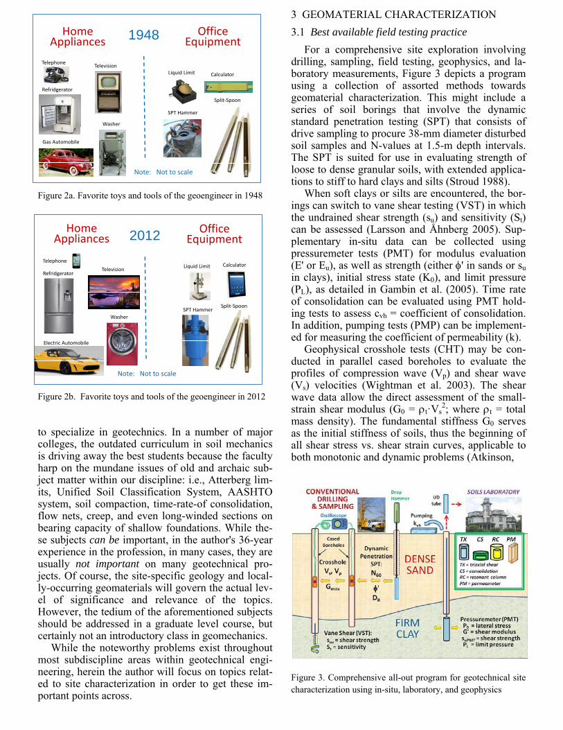
A look at the progress of our situation can be de-picted as shown in Figure 2, with a selection of tools of the trade presented for two chosen timeframes: 1948 and 2012. Surprisingly, our engineer is will-ingly open to adopting new technologies for home life, yet essentially relies on old school for her/his professional occupation.
As already mentioned, less than 5% of bachelors level civil engineering students actually go forward
HomeAppliances
Note: Not to scale
TelephoneTelevision
Refridgerator
Gas Automobile
Washer
Liquid Limit Calculator
Split‐Spoon
SPT Hammer
OfficeEquipment1948
Note: Not to scale
SPT HammerSplit‐Spoon
CalculatorLiquid LimitTelevision
Telephone
Refridgerator
Electric Automobile
Washer
HomeAppliances
OfficeEquipment2012
Figure 2a. Favorite toys and tools of the geoengineer in 1948
Figure 2b. Favorite toys and tools of the geoengineer in 2012
to specialize in geotechnics. In a number of major colleges, the outdated curriculum in soil mechanics is driving away the best students because the faculty harp on the mundane issues of old and archaic sub-ject matter within our discipline: i.e., Atterberg lim-its, Unified Soil Classification System, AASHTO system, soil compaction, time-rate-of consolidation, flow nets, creep, and even long-winded sections on bearing capacity of shallow foundations. While the-se subjects can be important, in the author's 36-year experience in the profession, in many cases, they are usually not important on many geotechnical pro-jects. Of course, the site-specific geology and local-ly-occurring geomaterials will govern the actual lev-el of significance and relevance of the topics. However, the tedium of the aforementioned subjects should be addressed in a graduate level course, but certainly not an introductory class in geomechanics.
While the noteworthy problems exist throughout most subdiscipline areas within geotechnical engi-neering, herein the author will focus on topics relat-ed to site characterization in order to get these im-portant points across.
3 GEOMATERIAL CHARACTERIZATION
3.1 Best available field testing practice
For a comprehensive site exploration involving drilling, sampling, field testing, geophysics, and la-boratory measurements, Figure 3 depicts a program using a collection of assorted methods towards geomaterial characterization. This might include a series of soil borings that involve the dynamic standard penetration testing (SPT) that consists of drive sampling to procure 38-mm diameter disturbed soil samples and N-values at 1.5-m depth intervals. The SPT is suited for use in evaluating strength of loose to dense granular soils, with extended applica-tions to stiff to hard clays and silts (Stroud 1988).
When soft clays or silts are encountered, the bor-ings can switch to vane shear testing (VST) in which the undrained shear strength (su) and sensitivity (St) can be assessed (Larsson and Åhnberg 2005). Sup-plementary in-situ data can be collected using pressuremeter tests (PMT) for modulus evaluation (E' or Eu), as well as strength (either ' in sands or su in clays), initial stress state (K0), and limit pressure (PL), as detailed in Gambin et al. (2005). Time rate of consolidation can be evaluated using PMT hold-ing tests to assess cvh = coefficient of consolidation. In addition, pumping tests (PMP) can be implement-ed for measuring the coefficient of permeability (k).
Geophysical crosshole tests (CHT) may be con-ducted in parallel cased boreholes to evaluate the profiles of compression wave (Vp) and shear wave (Vs) velocities (Wightman et al. 2003). The shear wave data allow the direct assessment of the small-strain shear modulus (G0 = t·Vs
2; where t = total mass density). The fundamental stiffness G0 serves as the initial stiffness of soils, thus the beginning of all shear stress vs. shear strain curves, applicable to both monotonic and dynamic problems (Atkinson,
Figure 3. Comprehensive all-out program for geotechnical site characterization using in-situ, laboratory, and geophysics

2000; Clayton 2011). In fact, this well-known fact is also missing from many textbooks, even though G0 has been shown relevant to practical foundation problems for over 2 decades (e.g., Burland 1989).
3.2 Sampling and laboratory testing
In addition to small drive samples, the borings al-so produce "undisturbed" thin-walled tube samples that are transported to the geotechnical laboratory. These samples usually have nominal diameters (75 mm < d < 150 mm) and lengths of about 1 to 1.2 m are obtained for laboratory testing of the intact soil materials under carefully controlled conditions using various devices, including: step-loaded oedometer, constant rate-of-strain consolidometer, fall cone, triaxial shear (CK0UC, CIUC, CIDC, etc), fixed and flexible walled permeameter, direct shear, simple shear, bender elements, and resonant column appa-ratuses. More specialized tests include: torsional shear, hydraulic Rowe cells, controlled gradient consolidometers, plane strain apparatus, radial permeameter, hollow cylinder, cubical triaxial, and directional shear devices. Laboratory testing on soil specimens can take days to weeks to months in order to obtain results and needed information about the in-place geomaterial stress state, flow characteris-tics, compressibility parameters, soil strength, stiff-ness behavior, and hydro-mechanical response.
One funny contradiction in lab testing relates to the two sister tests: direct shear box (DSB) and di-rect simple shear (DSS). While DSB results are rec-ognized to be effective stress parameters (e.g., c' = 0 and '), it is not utilized for undrained strength de-terminations on soils. In contrast, the DSS is acknowledged as a preferred test to obtain su in clays and silts (e.g., Ladd & DeGroot 2003), yet not rec-ommended for evaluating effective friction angles ' of these soils. Yet, the devices really differ only in the specimen box arrangement, where the DST has fixed sides on two box halves and the DSS has rotat-ing sides, otherwise very comparable tests. In fact, data on Ariake clay by both DST and DSS show nearly identical stress-strain-strength behavior (Tang et al. 1994).
As an aside comment, the author further believes that most geotechnical engineers would be surprised to learn that DSS testing to obtain su in clays is actu-ally a drained test conducted under conditions of maintaining constant volume. Of course, this con-cept fits nicely within the framework of critical-state soil mechanics (Holtz et al. 2011).
Of additional difficulty is the realization that la-boratory soil samples are often fraught with issues of sample disturbance which are unavoidable (Tanaka 2000; Lunne et al. 2006). In soft soils, improved re-sults can be obtained by using special samplers (e.g., Laval, Sherbrooke, JPN), however at great cost and extra field effort. Moreover, the local drilling opera-
tions and field procedures can affect the overall quality of results of lab testing. Undisturbed sam-pling of granular soils is now also possible by inno-vative freezing technology (Hoeg et al. 2000), yet also at great cost. [Note: a fellow geoengineer from Exxon-Mobil Corporation indicated to the author in 2003 that he paid $30k per frozen sand sample on a project.]
While this kind of elaborate program can produce the necessary information regarding geostratification and relevant soil engineering properties, it does so at great time and cost. In fact, the full suite of field testing, geophysics, and laboratory testing is so ex-pensive and of such long duration, a program of this level can only be afforded on relatively large scale projects with substantial budgets (say a range of US $300k to $1M+) and lengthy schedules (say 6 months to 2+ years).
3.3 Routine site exploration
On small- to medium-size geotechnical projects, economies of time and money restrict the amount of exploration and testing that can be performed. For many projects, the budgets can be < US $10k and times for implementation < 2 weeks. Nevertheless, the engineering analyses still demand a thorough knowledge regarding the site-specific geomaterials lying beneath the property of study. In those in-stances, budgets for investigations are too limited, such that insufficient information is obtained. In the USA, for example, a common occurrence is the uti-lization of a single field measurement (alias, SPT-N value) and basic lab testing (e.g., grain size and/or PI) are the only input parameters. A usual conse-quence is that undue conservatism is adopted to off-set the dearth of data and information needed to find a rational solution, as well as avoid litigation should more riskier solutions be implemented. This can re-sult in selecting choices for site development, deep foundations, retention systems, and ground modifcation that are unnecessary, unwarranted, and an extra expense for the new facilities.
3.4 Risks of inadequate site investigation
A poorly-conducted and inadequate subsurface exploration program can have significant outcomes on the final constructed facilities, including possible overconservative or unconservative solutions. Some potential consequences may include: (a) high con-struction costs due to unnecessary use of piled foun-dations or structural mats, whereas spread footings would have served adequately; (b) extra site prepa-ration time and expenses for ground modification techniques, when in fact, none were needed; (c) un-expected poor performance of foundations, em-bankments, retaining walls, and excavations; (d) in-stability or excessive movements because subsurface anomalies were not detected; and/or (e) litigation.

Regardless of budget and time, a geotechnical site investigation must still be performed and it needs to provide a reasonably sufficient amount of high-quality and varied types of subsurface data for anal-ysis so that the design produces an efficient, safe, ra-tional, and economical solution.
4 PARAMETER EVALUATION The evaluation of geotechnical parameters is ac-complished within a variety of means including: past experience and knowledge of the local geolo-gies, field testing, geophysics, and laboratory test-ing. The emphasis of most of our educational re-sources dwell primarily on laboratory tests as the means to this end. Usually, a cursory note on the use of geophysics and/or in-situ testing is given, with a few ill-chosen correlations or relationships given to relate that information back to the lab framework. A few pet peeves from the author's perspective are mentioned here to illustrate several dilemmas facing the profession. 4.1 Cohesion
The term "cohesion" is perhaps one of the most ill-used and vague terms in our discipline. In one sense, it is used to describe a coherency in the consistency of a soil sample; the particles hanging together as a unit. In the context of shear strength, it becomes nebulous as it can mean either the undrained shear strength (c = cu or su) or the effective cohesion inter-cept (c'), a parameter from the well-known linear Mohr-Coulomb strength criterion. The dilemma is depicted in Figure 4 which shows both of these "co-hesions" within a q-p' space. The issue of "cohesion" is likely made more diffi-cult because of poor textbook coverages on the mat-ter of soil strength and continued use of the old ar-chaic total stress friction and cohesion parameters, rather than the fundamentals of effective stress and critical-state soil mechanics.
Figure 4. Confusion in cohesion
In most soft saturated soils, the value of c' is actu-ally small and close to zero. A number of factors can contribute to lab tests showing c' > 0 including: strain rates of testing that are too fast, poor quality porewater pressure measurements, inadequate spec-imen saturation, and choice in effective confining stress levels. In fact, the latter play an important role when considered in light of the boundary yield sur-face which represents a 3-dimensional preconsol-idation of the soil stress history (see Figure 5).
Figure 5. Boundary yield surface and frictional envelope for Milwaukee clay (Schneider 2011) 4.2 Undrained shear strength
For clays subjected to short-term loading, a major parameter is the undrained shear strength (su = cu). On a plot of shear stress vs. shear strain, this is a value of shear stress chosen late in the curve corre-sponding either to peak conditions (max) or to fully-mobilized conditions at (1'/3')max, for the specific case of loading under constant volume. It has found applications in slope stability analysis, footing bear-ing capacity, pile side friction, embankments, exca-vations, and numerical modeling. In your normal textbook, it is treated as it were a simple-valued pa-rameter (su), yet alas it is one of the most complex and elusive variables in geotechnique. The undrained shear strength of any given clay (or for that matter, silt or sand) depends on many differ-ent factors, including: initial stress state (K0), strain rate (R), stress history (OCR or YSR), direction of loading (), intermediate boundary condition (b), time to failure (tf), and ageing, as well as the inher-ent fabric, structure, and sensitivity of the geomaterial. In fact, it is better to think in terms of a suite or family of undrained shear strengths (Kulhawy and Mayne 1990), analogous to a schizo-phrenic soil with many differing personalities. A summary of various su values from field and la-boratory test data from the national geotechnical ex-perimentation site at Bothkennar, UK are shown in Figure 6 (Hight et al. 2003). It is clear that a single value of su cannot be assigned to this deposit of soft silty clay. Instead, depending upon the method and mode of testing, a hierarchy of su exists, in fact quite a range of sixfold from the lowest to highest values.

Figure 6. Family of su profiles from various tests in Bothkennar clay, UK (after Hight et al. 2003) 4.3 In-situ test interpretation
For in-situ tests, no unified theory or framework has yet been put forth towards a general interpretation of all devices (SPT, CPT, VST, DMT, PMT) for a wide variety of various geomaterials (clays, silts, sands, mixed soils). Instead, each particular test has devel-oped rather independently within a particular appli-cation. Methodologies are based on theoretical, nu-merical, statistical, and empirical frameworks. For instance, data from the vane shear test in clays are usually analyzed within a limit equilibrium solu-tion, whereas pressuremeter results are considered within cylindrical cavity expansion. Alternative the-oretical solutions proposed for analysis of CPT data include: limit plasticity, strain path method, finite elements, discrete elements, hybrid cavity expan-sion-critical state, and dislocation theory. Usually, the approaches are established for two extreme cases of drainage, either: (a) undrained, applied to clays; or (b) fully-drained, applied to sands. In reality, many possible scenarios lie between the two condi-tions, as discussed by Randolph (2004) and Schnei-der et al. (2008). 4.4 Empirical correlations: improper usage
Because of the complexity of geomaterials, various databases have been compiled to cross-validate the results of laboratory and in-situ tests, check the rea-sonableness of theoretical solutions, and allow the development of statistical correlative relationships. These may also be used to help identify problematic soils that offer special difficulties in construction and long-term performance of built infrastructure; e.g., organic soils, fibrous peats, calcareous sands, collapsible soils, dispersive clays, loess, carbonates, and loose liquefiable sands and silts. Unfortunately, the geotechnical community tends to rely on a number of old empirical correlations that were derived from a small and early data set that are not at all applicable to the situations for which they
are now applied. Case in point: A rather recent text-book (circa 2008) indicates the following two corre-lations (cited back-to-back) for use in estimating the undrained shear strength of soft normally-consolidated clays: S = su/vo'NC = 0.11 + 0.0037 PI (%) (1a) S = su/vo'NC = '/100 (1b) These two equations are completely incompatible with one another. The first was developed by Skempton (1957) on the basis of raw (uncorrected) vane shear data on 19 soft clays (Figure 7), while the second represents an approximation to laboratory triaxial compression tests on the basis of critical-state soil mechanics (Wroth 1984). These two modes are completely different from one another, so an in-evitable inconsistency will be found should the ge-otechnical engineer go forth and use them.
Figure 7. Early trend of c/p' ratio with PI from raw vane data in soft clays (after Skempton 1957) A common usage for the aforementioned strength ratio S = su/vo'NC is to assess the inplace degree of preconsolidation by inverting the SHANSEP nor-malization scheme (Ladd, 1991):
(2)
where OCR = p'/vo' = overconsolidation ratio, p' = effective preconsolidation stress, vo' = effective overburden stress, and m = empirical parameter ≈ 0.80. A more fundamental expression is in fact de-rived from critical-state soil mechanics for the isotropically-consolidated triaxial compression (CIUC) mode (Wroth 1984):
(3)
m
NCvou
S
sOCR
/1'/
/1)'/(2
2c
vou
M
sOCR
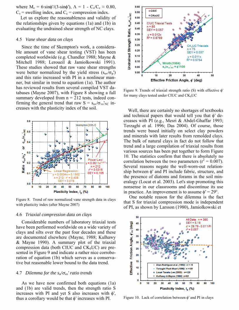
where Mc = 6∙sin'/(3-sin'), = 1 - Cs/Cc ≈ 0.80, Cs = swelling index, and Cc = compression index. Let us explore the reasonableness and validity of the relationships given by equations (1a) and (1b) in evaluating the undrained shear strength of NC clays. 4.5 Vane shear data on clays
Since the time of Skempton's work, a considera-ble amount of vane shear testing (VST) has been completed worldwide (e.g. Chandler 1988; Mayne & Mitchell 1988; Leroueil & Jamiolkowski 1991). These studies showed that raw vane shear strengths were better normalized by the yield stress (suv/p') and this ratio increased with PI in a nonlinear man-ner, but similar in trend to equation (1a). The author has reviewed results from several compiled VST da-tabases (Mayne 2007), with Figure 8 showing a full summary developed from n = 212 tests, indeed con-firming the general trend that raw S = suv/vo'NC in-creases with the plasticity index of the soil.
Figure 8. Trend of raw normalized vane strength data in clays with plasticity index (after Mayne 2007)
4.6 Triaxial compression data on clays
Considerable numbers of laboratory triaxial tests have been performed worldwide on a wide variety of clays and silts over the past four decades and these are documented elsewhere (Mayne, 1988; Kulhawy & Mayne 1990). A summary plot of the triaxial compression data (both CIUC and CK0UC) are pre-sented in Figure 9 and indicate a rather nice corrobo-ration of equation (1b) which serves as a conserva-tive but reasonable lower bound to the data trend.
4.7 Dilemma for the su/vo' ratio trends
As we have now confirmed both equations (1a)
and (1b) are valid trends, then the strength ratio S increases with PI and yet S also increases with ', thus a corollary would be that ' increases with PI.
Figure 9. Trends of triaxial strength ratio (S) with effective ' for many clays tested under CIUC and CK0UC
Well, there are certainly no shortages of textbooks and technical papers that would tell you that ' de-creases with PI (e.g., Mesri & Abdel-Ghaffar 1993; Terzaghi et al. 1996; Das 2004). Of course, those trends were based initially on select clay powders and minerals with later results from remolded clays. The bulk of natural clays in fact do not follow that trend and a large compilation of triaxial results from various sources has been put together to form Figure 10. The statistics confirm that there is absolutely no correlation between the two parameters (r2 = 0.007). Several reasons negate the well-worn-out relation-ship between ' and PI include fabric, structure, and the presence of diatoms and forams in the soil min-eralogy (Locat et al. 2003). Let's stop promoting this nonsense in our classrooms and discontinue its use in practice. An improvement is to assume ' = 29.
One notable reason for the dilemma is the fact that S for triaxial compression mode is independent of PI, as shown by Larsson (1980), Jamiolkowski et
Figure 10. Lack of correlation between ' and PI in clays

Figure 11. Strength ratio vs PI for clays tested in triaxial com-pression, simple shear, and extension modes (Ladd 1991)
Figure 12. Database trends for strength ratio vs PI for clays tested by CK0UC, DSS, and CK0UE modes
Figure 13. Summary of statistical trends of S vs PI for vane, compression, simple shear, and extension modes
al. (1985), and Ladd & DeGroot (2003). The trends from Ladd (1991) are shown in Figure 11 for three lab test modes. Again, drawing from the author's collection of data on a wide variety of clay soils in-deed confirms that the S ratio from CK0UC mode does not vary with plasticity index (Figure 12). For comparison, results are also compiled and presented from available DSS and CK0UE series on clays. In these cases, S for triaxial extension moderately in-creases with PI while S for simple shear slightly in-creases with PI. These larger data sets confirm the past findings of the aforementioned studies on the topic. Figure 13 provides a summary of the latest S trends with PI in comparison with those from Ladd (1991) for labora-tory modes and those from the recent VST datasets and Skempton's early work. It can be clearly seen that strength ratios from triaxial compression tests cannot be associated directly with vane shear results, as they are quite different. The consequences have led to conversion factors between TC-VST (Chan-dler 1987) as well as correction factors for the VST to provide su values appropriate for use in stability analyses and bearing capacity calculations (e.g., Larsson 1980; Schnaid 2010). 4.8 Critical-state soil mechanics One important subject missing from a number of introductory geotechnical textbooks is critical-state soil mechanics (CSSM). The framework of CSSM offers a rational effective stress coupling on consoli-dation and compressibility behavior of soils with the response to shearing (Figure 14). The approach easi-ly addresses positive vs. negative porewater pres-sures, contractive vs. dilative behavior, normally- and overconsolidated states, and drained vs. un-drained loading, as well as other possible conditions (partially-drained, cyclic). The large number of text-books omitting CSSM are enumerable. Notably, one introductory book of recent vintage that does cover CSSM is Atkinson (2007). Within a constitutive soil model of the CSSM type, a hierarchy of the various modes can help to explain the differences amongst different lab tests: CIUC, PSC, CK0UC, DSS, PSE, CK0UE, and CIUE (e.g., Kulhawy & Mayne, 1990; Whittle & Kavvadas, 1994). As the DSS is an intermediary mode, it sort of represents a good average value be-tween compression and extension, thus suitable as a liaison between the complex world of strength ani-sotropy and undergraduates who are obliged to take a bachelors level course on the topic of geo-mechanics. As such, the author developed a simple overview module on CSSM entitled "critical-state soil mechanics for dummies" available as a down-load from: geosystems.ce.gatech.edu for educa-tional purposes.

Figure 14. Outline of simplified CSSM framework
Figure 15. Strength ratio S for NC clays in DSS mode
Figure 16. Strength ratio S for OC clays in DSS mode Within the simplified CSSM, the undrained shear strength ratio for normally-consolidated clays in DSS can be evaluated as (Wroth 1984): S = su/vo'NC = ½ sin' (4)
which is seen to be quite reasonable when placed in comparison with data from well-documented clays (Figure 15). Of final note, the importance of stress history is contained within the CSSM framework and used to express the undrained strength ratio in the general case for DSS: su/vo'NC = ½ sin' OCR (5) The verification of this formulation is shown in Fig-ure 16 and helps to support a simple, yet reliable, approach in teaching undergraduate classes. The only exception to note is that the strength is reduced to 50% if the clay is fissured because of the extra weakness planes offered by discontinuities. 5 ENHANCED SITE INVESTIGATIONS
One path towards the modernization of an under-graduate education in geomechanics is to update the course materials on site investigation. This can in-clude new sections on available methods for drilling and sampling beyond the routine augering and rotary wash methods, specifically addressing: (1) direct push and (2) sonic technologies that offer faster con-tinuous collection of soils and/or rocks. A full sec-tion should be covered on noninvasive and borehole geophysical methods, both electromagnetic and me-chanical wave techniques (Campanella 1994). Final-ly, an entire chapter covering the basic in-situ tests: SPT, CPT, DMT, PMT, and VST should be ad-dressed, complete with recommendations for inter-pretation and their relationship to the laboratory tests (e.g., Schnaid 2010). Mention to specialized field and in-situ test devices can also be given to illustrate the full range of capabilities now available towards assisting geotechs in their challenging task. 5.1 The new exploration program
For routine site exploration, a modern approach for the year 2012 and beyond can now be recom-mended that includes: (a) initial areal mapping via noninvasive geophysical techniques; (b) physical vertical probings by hybrid in-situ tests for "ground truthing" (Figure 17). These together offer benefits in terms of improved coverage, insurance, reliabil-ity, productivity, and economics, compared with conventional methods. In a traditional site investigation, rotary drilled borings or soundings are typically positioned on an established grid pattern over the project building site, say 30 m on center, in an attempt to hopefully capture any lateral variants in geostratigraphy across the site. Of course, this is merely a trial-and-error attempt since the gridded area may or may not coin-cide with Mother Nature's original coordinate sys-tem. For instance, it would be completely plausible that a buried ravine, or old natural stream, or other

Figure 17. Modern approach to site investigation using combi-nation of noninvasive geophysics and hybrid in-situ probings
unknown anomaly might occur between the chosen grid points for the borings. Missing this important feature might result in construction difficulties, changed conditions, ground modification, different foundation system, and/or litigation. 5.2 Noninvasive geophysics
A logical solution to detecting heterogeneity is the utilization of high-frequency geophysical methods: electrical resistivity surveys (ERS), ground penetrat-ing radar (GPR), and/or electromagnetic conductivi-ty (EMC) for mapping the site area for relative dif-ferences. Not only are these geophysical surveys quick and economical to perform, they offer a chance to rationally direct the probes and soundings of the site investigations towards any variants on the property, thus focusing on the mapping of relative differences in dielectric or resistivity properties. It is also possible to utilize the geophysical sur-face wave methods (SASW, MASW, CSW) for such purposes, albeit at higher cost and degree of imple-mentation.
5.3 Hybrid probes: seismic cone and dilatometer
Hybrid exploratory devices that combine direct-push electromechanical probes with downhole wave geo-physics offer an optimized means to collect data, as information at opposite ends of the stress-strain-strength curve are obtained at one time in a single sounding (Mayne 2010). Coupled with dissipatory phases, these include the seismic piezocone test (SCPTù) and seismic flat dilatometer test (SDMTà). The seismic cone and seismic dilatometer are not new, but were developed three decades ago (Campanella et al. 1986; Hepton 1988). The SCPTù offers up to 5 separate readings with depth, including: cone tip resistance (qt), sleeve fric-tion (fs), porewater pressure (u2), time rate of dissi-
pation (t50), and downhole shear wave velocity (Vs), as detailed by Mayne and Campanella (2005). Moreover, the data are recorded continuously, digi-tally, and directly into a computer data acquisition unit for immediate post-processing, so that if neces-sary, on-site decisions can be made right then by the geotechnical engineer, else sent by wireless trans-mission to the chief engineer at the office for review. With the newest digital electronic systems, addition-al modules can provide downhole readings on resis-tivity, dielectric, and electrical conductivity. An illustrative example of a representative SCPTù sounding from New Orleans, Louisiana is presented in Figure 18 showing four separate measurements with depth. The sounding was completed as part of the levee restoration project of the suburb area east of the city. The readings clearly show alternating layers of clay/sand strata in the upper 9 m followed by a thick 11-m soft clay layer to 20 m depth, under-lain by a 10-m thick sand stratum extending beyond the termination depth at 30 m. A full dissipation is evident at 17 m with partial dissipatory results at 13-14 m and 19 m. As an alternate or supplement to seismic cone testing, the SDMTà can provide as many as five or six independent readings can be obtained with depth, usually at 0.02m intervals, including: contact pres-sure (p0), expansion pressure (p1), deflation pressure (p2), time rate decay (tflex), compression wave ve-locity (Vp), and shear wave velocity (Vs). Details are given by Marchetti et al. (2008).
Figure 18. Representative seismic piezocone sounding from New Orleans East, Louisiana 5.4 Universal laboratory testing apparatus
In concert with the above field hybrid tests that ob-tain multiple geoparameters from a single sounding, similar devices can be developed for the laboratory program. A conceptual device is presented in Figure 19 that would optimize the types and amount of data information collected from each soil specimen. The hybrid lab test would include a combination of con-stant-rate-of-strain consolidometer (CRS) with a di-

rect simple shear (DSS) apparatus and additional sets of bender elements (BE) to provide a full suite of geotechnical engineering values, including com-pressibility (Cr, Cc, Cs, D), stiffness (Gmax, G), strength (max, su, ', c'), rheological behavior (Ce, cvh, ), and flow characteristics (k), as well as state parameters (eo,t, p', OCR or YSR).
Figure 19. Conceptual all-in-one hybrid laboratory test 6 CONCLUSIONS
Current introductory courses and textbooks on geotechnics focus on a laboratory-based approach to solving problems in our field. While this has merit from a mechanics framework, 95% of the civil engi-neering students go on to major in different occupa-tions, thus have a distorted view of our profession and its capabilities. Moreover, the 5% who do be-come practicing geoengineers are ill-equipped to tackle the site exploration program properly, as this is mainly acquired through use of geophysical and in-situ field testing. A consequence is that the practi-tioner falls back to the conventional methods of rota-ry drilling and sampling, often without sufficient funding for the extensive sets of lab testing to follow through on the analyses. In the vast majority of routine projects, the selec-tion of geoparameters is accomplished by resorting to old (sometimes incorrect) empirical correlations based on simple indices, rather than the fundamental values that really require triaxial, resonant column, and/or other significant lab testing. A modernization of the educational focus on the types, advantages, and interpretation of in-situ tests, such as the seismic piezocone and seismic dilatometer, would benefit the geotechnical community in terms of image, un-derstanding, and data optimization, as well as miti-gating possible legal issues.
7 ACKNOWLEDGMENTS
The author appreciates the support of ConeTec of Richmond, BC and the US Dept. of Energy at the Savannah River Site, SC towards research activities on in-situ testing and site characterization.
8 REFERENCES Atkinson, J.H. (2000). Non-linear soil stiffness in routine de-
sign. Géotechnique 50 (5): 487 –508. Atkinson, J.H. (2007). The Mechanics of Soils and Founda-
tions. Taylor & Francis Group, London: 442 p. Broms, B.B. & Flodin, N. (1988). History of soil penetration
testing, Penetration Testing 1988, (Proc. ISOPT, Orlando), Balkema, Rotterdam: 157-220.
Burland, J.B. (1989). Small is beautiful: The stiffness of soils at small strain. Canadian Geotechnical J. 26 (4): 499-516.
Campanella, R.G., Robertson, P.K. and Gillespie, D. (1986). Seismic cone penetration test. Use of In-Situ Tests in Geot. Engrg. (GSP 6), ASCE, Reston, VA: 116-130.
Campanella, R.G. (1994). Field methods for dynamic geotech-nical testing: an overview of capabilities and needs. Dy-namic Geotechnical Testing II, ASTM STP 1213, West Conshohocken, PA: 3-23
Chandler R.J. (1988). The in situ measurement of the un-drained shear strength of clays using the field vane. Vane Shear Strength Testing in Soils: Field and Laboratory Stud-ies, ASTM STP 1014. West Conshohocken, PA: 13–44.
Clayton, C.R.I. (2011). Stiffness at small strain: research and practice. Geotechnique 61 (1): 5-37.
Das, B.M. (2004). Principles of Foundation Engineering, Fifth Edition, Thomson/Brooks/Cole, London: 743 p.
Diaz-Rodriguez, J.A., Leroueil, S. and Aleman, J.D. (1992). Yielding of Mexico City clay and other natural clays. J. Geotechnical Engineering 118 (7): 981-995.
Dyvik, R., Berre, T., Lacasse, S. and Raadim, B. (1987). Com-parison of truly undrained and constant volume direct sim-ple shear tests. Géotechnique 37 (1): 3 –10.
Gambin, M., Magnan, J-P., and Mestat, Ph., ed. (2005). Intl. Symposium: 50 Years of Pressuremeters (Proc. ISP5- Pressio 2005), Vols 1 & 2, Laboratoire Central des Ponts et Chaussée, Paris: 1484 p.
Hepton, P. (1988). Shear wave velocity measurements during penetration testing. Penetration Testing in the UK, Thomas Telford, London: 275-278.
Hight, D.W., Paul, M.A., Barras, B.F., Powell, J.J.M., Nash, D.F., Smith, P.R., Jardine, R.J. and Edwards, D.H. (2003). The characterisation of the Bothkennar clay. Characterisa-tion & Engineering Properties of Natural Soils, Vol. 1 (Proc. Singapore), Swets & Zeitlinger, Lisse: 543-597.
Hoeg, K, Dyvik, R., and Sandbækken, G. (2000). Strength of undisturbed versus reconstituted silt and silty sand speci-mens. J. Geotechnical & Geoenvironmental Engineering 126 (7): 606-617.
Holtz, R.D., Kovacs, W.D. and Sheahan, T.C. (2011). An In-troduction to Geotechnical Engineering, Pearson/Prentice-Hall, New York: 864 p.
Jamiolkowski, M., Ladd, C.C., Germaine, J. and Lancellotta, R. (1985). New developments in field and lab testing of soils. Proc. 11th Intl. Conf. Soil Mechanics & Foundation Engineering, Vol. 1, San Francisco: 57-153.
Kulhawy, F.H. and Mayne, P.W. (1990). Manual on Estimat-ing Soil Properties for Foundation Design. Report EL-6800, Electric Power Research Institute, Palo Alto: 306 p.

Lacasse, S. (1985). Design parameters of clays from in-situ and lab tests. Proc. Symposium on New Concepts in Geotech-nical Engineering, Rio de Janeiro; also contained in Nor-wegian Geotechnical Inst. Report No. 52155-50, Oslo.
Ladd, C.C. (1991). Stability evaluation during staged construc-tion. J. Geotechnical Engineering 117 (4): 540-615.
Ladd, C.C. and DeGroot, D.J. (2003). Recommended practice for soft ground site characterization. Soil & Rock America 2003, Vol. 1 (Proc. 12th PanAm Conf. Soil Mechanics), Verlag Glückhauf, Essen: 3-57.
Larsson, R. (1980). Undrained shear strength in stability calcu-lations of embankments and foundations on soft clays. Ca-nadian Geotechnical J. 17 (4): 591-602.
Larsson, R. and Åhnberg, H. (2005). On the evaluation of un-drained shear strength and preconsolidation pressure from common field tests in clay. Canadian Geotechnical J. 42 (4): 1221-1231.
Leroueil, S. and Jamiolkowski, M. (1991). Exploration of soft soil and determination of design parameters. Proc. Geo-Coast'91, Vol. 2, Yokohama, Port & Harbour Research In-stitute: 969-998.
Locat, J., Tanaka, H., Tan, T.S., Dasari, G.R. and Lee, H. (2003). Natural soils: geotechnical behavior and geological knowledge. Characterization and Engineering Properties of Natural Soils, Vol. 1 (Proc. Singapore), Swets & Zeitlinger, Lisse: 3 - 28.
Lunne, T., Berre, T., Andersen, K.H., Strandvik, S. and Sjursen, M. (2006). Effects of sample disturbance and con-solidation procedures. Canadian Geot. J. 43 (7): 726-750.
Marchetti, D., Marchetti, S., Monaco, P. and Totani, G. (2008). Experience with the seismic dilatometer in various soils. Geotechnical & Geophysical Site Characterization, Vol. 2 (Proc. ISC-3, Taipei), Taylor & Francis, UK: 1339-1345.
Mayne, P.W. (1988). Determining OCR in clays from laborato-ry strength. J. Geotechnical Engrg. 114 (1): 76-92.
Mayne, P.W. and Campanella, R.G. (2005). Versatile site char-acterization by seismic piezocone tests. Proceedings 16th ICSMGE, Vol. 2 (Osaka), Millpress, Rotterdam: 721-724.
Mayne, P.W. and Mitchell, J.K. (1988). Profiling OCR in clays by field vane. Canadian Geotechnical Journal, Vol. 25 (1): 150-157.
Mayne, P.W. (2007). In-situ test calibrations for evaluating soil parameters. Characterization & Engineering Properties of Natural Soils, Vol. 3 (Proc. Singapore 2006), Taylor & Francis, London: 1602-1652.
Mayne, P.W. (2010). Regional report for North America. Pro-ceedings, 2nd Intl. Symposium on Cone Penetration Testing (CPT'10), Vol. 1, Huntington Beach, California: 275-312. Download from: www.cpt10.com
Mesri, G. and Abdel-Ghaffar, M.E.M. (1993). Cohesion inter-cept in effective stress stability analyses. J. Geotechnical Engineering 119 (8): 1229-1249.
Randolph, M.F. (2004). Characterization of soft sediments for offshore applications. Geotechnical and Geophysical Site Characterization, Vol. 1 (Proc. ISC-2, Porto), Millpress, Rotterdam: 209-232.
Schnaid, F. (2010). In-Situ Testing in Geomechanics: The Main Tests. Taylor & Francis Group, NY: 328 p.
Schneider, J.A., Randolph, M.F., Mayne, P.W., and Ramsey, N.R. (2008). Analysis of factors influencing soil classifica-tion using normalized piezocone parameters. J. Geotech-nical & Geoenvironmental Engrg 134 (11): 1569-1586.
Schneider, J.A. (2011). Mechanisms controlling displacement pile resistance in relation to CPTU parameters. PPT Slide Set. University of Wisconsin, Madison.
Skempton, A.W. (1957). Discussion. Proc. Institution of Civil Engineers, London, Vol. 7: 305-307.
Sowers, G.F. (1981). There were giants on the Earth in those days. Journal of the Geotechnical Engineering Division (ASCE), Vol. 107, No. 4, April 1981: 383-419.
Stroud, M.A. (1988). The standard penetration test: its applica-tion and interpretation. Penetration Testing in the U.K., Thomas Telford, London: 29-49.
Tanaka, H. (2000). Sample quality of cohesive soils: Lessons from three sites: Ariake, Bothkennar, and Drammen. Soils and Foundations 40 (4): 54-74.
Tang, Y.X., Hanzawa, H. and Yasuhara, K. (1994). Direct shear and direct simple shear test results on a Japanese ma-rine clay. Pre-Failure Deformation of Geomaterials, Vol. 1 (Sapporo), Balkema, Rotterdam: 107-112.
Terzaghi, K. (1925). Erdbaumechanik auf Bodenphysikalischer Grundlage, Franz Deuticke, Leipzig und wein, 399 p.
Terzaghi, K. (1943). Theoretical Soil Mechanics. Chapman & Hall; Wiley & Sons, New York: 510 p.
Terzaghi, K., Peck, R.B. and Mesri, G. (1996). Soil Mechanics in Engineering Practice, Wiley & Sons, New York: 519 p.
Whittle, A.J. and Kavvadas, M.J. (1994). Formulation of MIT-E3 constitutive model for overconsolidated clay. Journal of Geotechnical Engineering 120 (1): 173-224.
Wightman, W.E., Jalinoos, F., Sirles, P. and Hanna, K. (2003). Application of Geophysical Methods to Highway Related Problems. Contract Report No. DTFH68-02-P-00083, Fed-eral Highway Administration, Washington, DC: 742 p.
Wroth, C.P. (1984). The interpretation of in-situ soil tests (24th Rankine Lecture). Geotechnique 34 (4): 449-489.