quality manual - vlsi · quality manual 4. quality system of vlsi solution 4.1.general the purpose...
TRANSCRIPT

Quality Manual
Revision history
Rev. Date Author Affected chapters
Description
1.4 13.7. 2000 JS All Original version
1.5 16.10. 2000 JS All Operations VP -> Operation Manager, Sales & Marketing VP -> Sales & Marketing Manager.
1.6 14.11. 2000 JS 5.1, 5.3, 5,7 first sentence removed (5.1.1), ECN report generated
1.7 4.5. 2001 JS All Updated according to ISO9001:2000
1.8 9.9. 2002 JS 5.9 Update
2.2 30.8.2007 TK Major upgrade
2.3 11.2.2008 JS Typo corrections, Appendixes added.
2.4 11.6.2008 JS 8.5.2 Contents of 8D report added.
2.5 28.9.2010 TK 5.5.1 Organization structure updated
2.6 18.8.2010 TK+JS 7.5.3 Product naming policy upgrade to include package variants
Approval list:
Name Title DateReviewed by: Jori Simpanen Quality Engineer 28.9.2010Approved by: Teppo Karema CEO 28.9.2010
Quality Manual
Table of Contents1 Scope..................................................................................................................................3
1.1. Introduction..................................................................................................................31.2. Exclusion form ISO standard.......................................................................................3
2. References.........................................................................................................................43. Terms and Definitions.......................................................................................................54. Quality system of VLSI Solution......................................................................................6
4.1. General........................................................................................................................64.2. Documentation requirements.......................................................................................6
4.2.1. General.............................................................................................................64.2.2. Quality manual..................................................................................................64.2.3. Control of documents........................................................................................74.2.4. Control of Records............................................................................................7
5. Management responsibility..............................................................................................75.1. Management commitment...........................................................................................75.2. Customer focus...........................................................................................................75.3. Quality policy...............................................................................................................75.4. Planning.......................................................................................................................8
5.4.1. Quality objectives..............................................................................................85.4.2. Quality management system planning..............................................................8
5.5. Responsibility, authority and communication...............................................................85.5.1. Responsibility and authority...............................................................................85.5.2. Management representative............................................................................105.5.3. Internal communication...................................................................................10
5.6. Management review..................................................................................................106. Resource management...................................................................................................10
6.1. Provision of resources...............................................................................................106.2. Human resources.......................................................................................................116.3. Infrastructure..............................................................................................................116.4. Work environment......................................................................................................11
7. Product realization..........................................................................................................117.1. Planning of the project...............................................................................................117.2. Customer-related processes......................................................................................11
7.2.1. Determination of requirements related to the project.......................................117.2.2. Review of requirements of the project.............................................................117.2.3. Customer communication................................................................................12
7.3. Design and development...........................................................................................127.3.1. Design and development planning..................................................................127.3.2. Design and development inputs......................................................................127.3.3. Design and development outputs....................................................................127.3.4. Design and development review.....................................................................127.3.5. Design and development verification...............................................................137.3.6. Prototyping......................................................................................................137.3.7. Transfer to Production.....................................................................................137.3.8. Control of design and development changes..................................................14
7.4. Purchasing.................................................................................................................147.4.1. Purchasing process.........................................................................................147.4.2. Purchasing information....................................................................................147.4.3. Verification of purchased product....................................................................14
7.5. Production.................................................................................................................157.5.1. Control of production.......................................................................................157.5.2. Validation of process for production.................................................................157.5.3. Identification and traceability...........................................................................15
Rev. 2.6 Page 2 (27)

Quality Manual
7.5.4. Customer property...........................................................................................167.5.5. Preservation of product...................................................................................17
7.6. Control of monitoring and measuring devices............................................................178. Measuring, analysis and improvement.........................................................................17
8.1. General......................................................................................................................178.2. Monitoring and measurement....................................................................................17
8.2.1. Customer satisfaction......................................................................................178.2.2. Internal audit...................................................................................................178.2.3. Monitoring and measurement of processes.....................................................188.2.4. Monitoring and measurement of product.........................................................18
8.3. Control of nonconforming product..............................................................................188.4. Analysis of data.........................................................................................................188.5. Improvement..............................................................................................................19
8.5.1. Continual improvement...................................................................................198.5.2. Corrective action.............................................................................................198.5.3. Preventive action.............................................................................................19
Appendix 1. New ASIC project flow..................................................................................21 Appendix 2. Design flow..................................................................................................22 Appendix 3. Prototyping flow...........................................................................................23 Appendix 4. Transfer to production flow...........................................................................24 Appendix 5. Production flow............................................................................................25 Appendix 6. PO review flow.............................................................................................26 Appendix 7. PO execution flow........................................................................................27
1 Scope
1.1. IntroductionThis Quality Manual is issued and controlled by VLSI Solution Oy (VLSI) that has headquarters in Tampere, Finland.
VLSI is a designer and a manufacturer of semiconductors and specialize in the design and fabless production of mixed signal integrated circuits.
This manual describes the Quality System of VLSI. It provides the authorization andcontrol of related activities and their associated documentation.
The Quality Manual is made according to European Standard EN ISO 9001, which is approved by European Committee for Standardization (CEN) on 15.12. 2000.
1.2. Exclusion form ISO standardThe Quality Management System has been designed to be totally compliant to ISO 9001:2000 in all aspects that apply to the organization’s operations and needs and does not detract from the ability or responsibility to provide product that fulfils customer and applicable regulatory requirements.
The first exception within clause 7, Product Realization, is “service provisions.” VLSI products are of the nature that, once sold to customers, there are no servicing operations required.
Rev. 2.6 Page 3 (27)

Quality Manual
The second exception is validation of processes (7.5.2). Products can all be verified by subsequent measurement or monitoring. These are addressed as “standard” processes of product test and reliability monitoring, which are described in other sections of this manual.
2. ReferencesEN ISO 9001:2000, Quality management systems - Requirements
Rev. 2.6 Page 4 (27)
Quality Manual
3. Terms and Definitions
Agreement A properly executed and legally binding contract such as confirmed purchase order.
ASSP VLSI Solution's own product
ASIC
BOD
IC for the customer is referred as ASIC
Board of Directors
FA
FVI
Finance and accounting
Final Visual Inspection
IC
Nonconformity
Integrated circuit
A product that does not fulfil the specified requirements.
P
Phase
President of VLSI Solution
Milestone of the project
QM Quality Manual
QP Quality Procedure
QD Quality Document
QR
Subcontractor, Vendor
Quality Record
A company or organization that provide services to the VLSI Solution. This is equal to term "supplier" used in the ISO9001:2000.
VP Vice President of VLSI Solution
VLSI VLSI Solution
Rev. 2.6 Page 5 (27)
Quality Manual
4. Quality system of VLSI Solution
4.1. GeneralThe purpose of this Quality system is to ensure that the requirements of the Quality policy will be fulfilled at VLSI Solution.
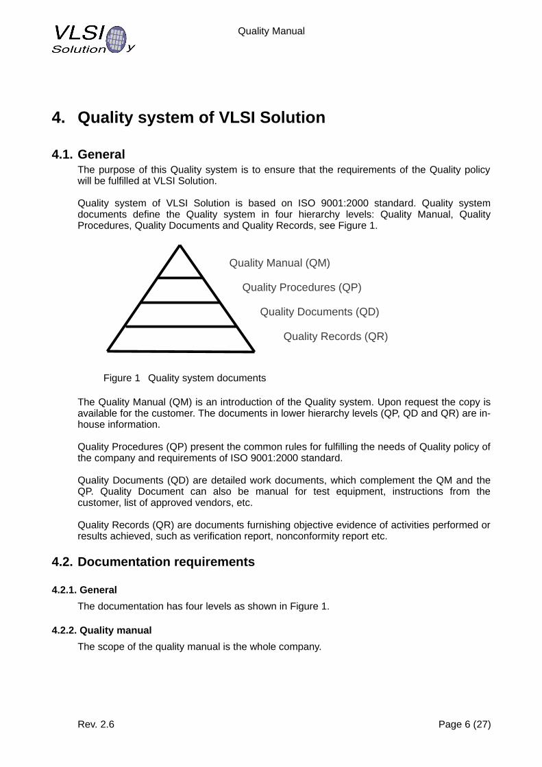
Quality system of VLSI Solution is based on ISO 9001:2000 standard. Quality system documents define the Quality system in four hierarchy levels: Quality Manual, Quality Procedures, Quality Documents and Quality Records, see Figure 1.
Figure 1 Quality system documents
The Quality Manual (QM) is an introduction of the Quality system. Upon request the copy is available for the customer. The documents in lower hierarchy levels (QP, QD and QR) are in-house information.
Quality Procedures (QP) present the common rules for fulfilling the needs of Quality policy of the company and requirements of ISO 9001:2000 standard.
Quality Documents (QD) are detailed work documents, which complement the QM and the QP. Quality Document can also be manual for test equipment, instructions from the customer, list of approved vendors, etc.
Quality Records (QR) are documents furnishing objective evidence of activities performed or results achieved, such as verification report, nonconformity report etc.
4.2. Documentation requirements
4.2.1. General
The documentation has four levels as shown in Figure 1.
4.2.2. Quality manual
The scope of the quality manual is the whole company.
Rev. 2.6 Page 6 (27)
Quality Manual (QM)
Quality Procedures (QP)
Quality Documents (QD)
Quality Records (QR)
Quality Manual
4.2.3. Control of documents
Document review, approval and issue is controlled by the authorized personnel. Changes to the document are reviewed and approved by the same persons that reviewed and approved the original version, unless otherwise agreed by the management.
The Quality Manual and Quality Procedures documents are available via www browser in company's intranet. Only the latest approved version of a document can be accessed. The hard copies of these documents are uncontrolled copies.
Recoverability of the files is possible by automatic backups.
4.2.4. Control of Records
Quality Records are maintained to demonstrate conformance to specified requirements and the functioning as per the Quality system.
The subcontractors are responsible for maintaining agreed quality records at their facility. Test data records are automatically copied (mirrored) to VLSI Solution via secure ftp.
The Quality Records are stored to the file system. They are available at least three years.
5. Management responsibility
5.1. Management commitmentChief Executive Officer/ President and all management at VLSI are committed to the Quality Management System as presented in this Quality Manual. This commitment is not limited to the initial development of this system, but to its continual improvement through the implementation of necessary management responsibilities. The primary responsibilities of the Management related to the quality are:
Communicate to all personnel the importance of meeting customer, regulatory and/or legal requirementsEstablish the quality policy and quality objectives. Conduct management reviewsProvide resources to achieve quality objectives
5.2. Customer focusThe Quality Management System provides specific direction toward ensuringthat customer requirements are determined and that these requirements are addressed.Implementation of customer-related processes, as defined in paragraph 7.2.
5.3. Quality policyQuality policy of VLSI Solution is
Rev. 2.6 Page 7 (27)
Customer needs and requirements are met by innovative circuit technologies
Each person is responsible for continuous improvement of services and products

Quality Manual
5.4. Planning
5.4.1. Quality objectives
The CEO/President and his staff shall establish measurable quality objectives on a continuing basis as a part of the management review process. These objectives, results of attaining these objectives and actions taken, shall also be part of the management review quality records.
Actions taken as a result of the review of these measures may take the form of corrective actions, preventive actions or revising goals for purpose of continuous improvement efforts. These may relate to any of the internal processes that are inherent to the Quality Management System or to address ongoing activities that will impact requirements to attain customer satisfaction.
5.4.2. Quality management system planning
Quality Procedures provide the plans for implementing all processes of the Quality Management System.
Quality Manager will ensure that this system is carried out to meet the set requirements and objectives.
5.5. Responsibility, authority and communication
5.5.1. Responsibility and authority
The organization structure of VLSI Solution is presented in Table 1.
Board of Directors
CEO (President)
QualitySalesand
MarketingProduction
Supportand SW
Development
Design DSPeaker InformationTechnology
Table 1 Organization
5.5.1.1. Board of Directors Supervises the activities of the President.Has the power of decision in matters which are of far-reaching or exceptional nature.Represents the VLSI Solution.Executes the decisions made by the shareholders´ meeting.
5.5.1.2. The CEO of VLSI Solution Approves of the Quality System.Manages the day-to-day business of the VLSI Solution.Is responsible for the reliability and conformity to law of the keeping and maintaining of books and the financial administration.Represents the VLSI Solution as regards duties or fields of duties falling within his competence.
Rev. 2.6 Page 8 (27)

Quality Manual
Is for his part the responsible for the result, development and cash flow of the VLSI Solution.Provides appropriate reports and information for Board of Directors (such as budget of the year).Initiates improvements to personnel.
5.5.1.3. Production Manager Is responsible for technical aspects of manufacturing including planning, test and quality.Negotiates the price, production volume and other necessary issues with the wafer manufacturer, assembly and test subcontractors to achieve lowest cost, highest quality for the required production volume.Monitors the reports of delivery performance, yields, error levels, cycle times and quality loss.Ensures that the delivered products meet the requirements and specifications set by the customer and VLSI Solution.Initiates corrective and preventive actions for nonconformities related to the IC production.
5.5.1.4. Design Manager Oversees, supports and controls Project teams to ensure effective execution of designs in compliance to established procedures and in accordance to company goals and objectives.Supports Production Manager on issues related to Prototyping and Transfer to Production.Prepares quotations for design and research projects, Prototyping and Transfer to Production.Allocates resources to projects.Contacts to customers in administrative matters (schedule and cost).Reviews and approves Project plans and specifications.Initiates and reviews corrective and preventive actions for nonconformities related to design.
5.5.1.5. Sales and Marketing Manager Analyse, plan and implement marketing and sales activities.Monitor how target markets respond to marketing efforts.Appoints and co-operates with Distributors to maximize the sales and profit.Provides sales forecasts to Production Manager and President.Sets target sales numbers of Distributors.Makes efforts to retain loyal customers.Initiates corrective and preventive actions for nonconformities related to sales and marketing.
5.5.1.6. Support and Software Development ManagerDirects and coordinates day-to-day technical support operations.Provides technical assistance and support to customers and internal users. Helps in technical matters Sales and Marketing effort.Prepares quotations for support projects.Allocates resources to support and software projects.Contacts to customers in technical matters.Reviews product specifications.Initiates and reviews corrective and preventive actions for nonconformities related to technical support and software development.
5.5.1.7. DSPeaker ManagerManages the day-to-day business of the DSPeaker spin-off business segment.Represents the DSPeaker.
Rev. 2.6 Page 9 (27)

Quality Manual
Develops sales and distribution channel for DSPeaker products.Provides appropriate reports and information of DSPeaker activities and plans for CEO and Board of Directors (such as product roadmap, sales report and profit report).Initiates improvements to DSPeaker personnel.Initiates and reviews corrective and preventive actions for nonconformities related to DSPeaker products.
5.5.1.8. Information Technology ManagerManages the information systems servers and clientsManages the design and administrative data and backupsEvaluates and decides design tools based on budgetDevelops tools and bridges between commercial tools for better quality and profitability of products.Initiates and reviews corrective and preventive actions for nonconformities related to the Information Technology.
5.5.2. Management representative
Quality Manager represents top management inimplementation and maintaining the quality systemreporting the performance and need for improvement to top management
5.5.3. Internal communication
Communication between various levels within VLSI Solution is maintained. As a minimum it consist of:
System definition through the Quality ManualCommunications network (INTRANET) that provides access to documents to all usersDefined directory structure for design projectsDepartment meetings (weekly)Project meetings (weekly) to address results, problem and plans of the project
5.6. Management reviewThe Management review team reviews at least once per year the effectiveness of the quality system and considers any update needs in response to observed nonconformities or organizational changes. Records of these meetings are maintained and the results are informed to the personnel.
6. Resource management
6.1. Provision of resourcesThe resources are controlled within the budgeting cycle occurring annually. Department managers have the opportunity to request required resources that are necessary to implement and/or improve the Quality Management System or to address needs to achieve customer satisfaction. These include equipment as well as human resources. If special needs arise during the course of the year, between budget cycles, budget allocations are reviewed with the top management in order to make necessary adjustments.
Rev. 2.6 Page 10 (27)
Quality Manual
6.2. Human resourcesDepartment managers are responsible to assign an appropriate job grade to each position.
Each job grade has defined competencies based on appropriate education, training, skills, and experience needed for the job type and level of responsibility.
New personnel must fulfil the defined job grade of their position.
New personnel is trained to the quality system.
Department managers determine when training is needed and take action to initiate it. Quality department is responsible in keeping the training records.
6.3. InfrastructureTop management aligns strategic objectives and technical road maps to market direction. President of the company prepares a budget for the BOD to meet the business objectives. Purchasing of new facilities, utilities and equipment is based on the budget that has been approved by BOD.
6.4. Work environmentIn maintaining an acceptable work environment, VLSI is committed to maintain its facilities in a safe and healthy manner that is in compliance with all applicable laws and regulations.
7. Product realization
7.1. Planning of the projectThe product realization uses common templates and design reviews for the product management, common design flows and practices for the design, verification, validation and qualification.
7.2. Customer-related processes
7.2.1. Determination of requirements related to the project
New projects are prepared by Project Managers together with the Design Manager. The major document is preliminary device specification and project plan.
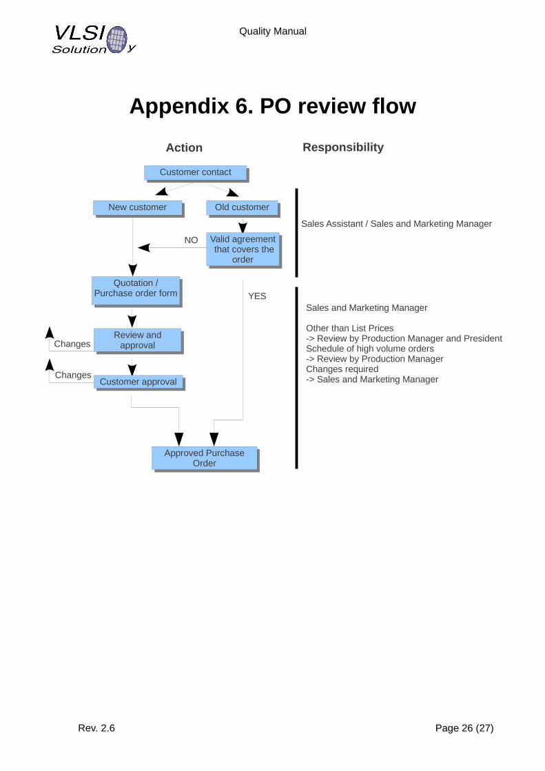
7.2.2. Review of requirements of the project
Prior to commitment to supply project or product to the customer it is checked thatrequirements are adequately specified by the customerVLSI has capability to meet the requirements in the given timethe agreements cover the requested service
The flow diagrams are shown in the Appendixes 1 and 6.
The project status vs plan is checked once per week in the internal weekly meetings and customer is contacted when update is needed.
Rev. 2.6 Page 11 (27)

Quality Manual
7.2.3. Customer communication
The Project Manager is the main communication channel to the customer in ASIC projects. He will share the information from the customer to the project team.
For qualified ASSP products the datasheets and contact persons are maintained and available on a web page. Web page has also General Terms of Sale and RMA Policy of VLSI.
7.3. Design and development
7.3.1. Design and development planning
A project plan is prepared for each project. Organizational and technical interfaces, schedule, verification and validation procedures are decided and recorded. The project plan is reviewed and approved in the design review (DR1). The project plan is updated during the project when necessary. Flow diagram of Design phase is in Appendix 2.
7.3.2. Design and development inputs
The product requirements are collected into Device Specification and Project Plan. Device Specification is internal document of VLSI describing to other designers how things are done. Depending on the project it can be replaced by Data Sheet that describes the functionality and target performance but not how things are done. For new products Evaluation Board is designed and Test Specification is created.
7.3.3. Design and development outputs
Design output depends on the project. It is typically software code, layout database in GDS II format, test program, documentation and loadboard or evaluation board.
7.3.4. Design and development review
Reviews are implemented to analyze the results of verification, validation and to ensure that the design output meets the requirements specified in the design input. Problems and schedules are also addressed during the reviews. Records of the results of the reviews and any necessary actions are maintained. See the Figure below.
Rev. 2.6 Page 12 (27)
Engineering Sample
EvaluationEvaluation
Design ReviewDesign Review
VerificationVerification
Designoutput
Designprocess
Designinput
Customerneeds
DR1DR2 DR3 DR4
Prototype
QualificationQualification

Quality Manual
Figure 2 Design and development reviews
7.3.5. Design and development verification
Design verification is done by the designers during the design process. Design verification is based on test bench that will simulate the designed block and compare the result with the expected result. Complete verification is done by using DR3 Checklist that is attached to the DR3.
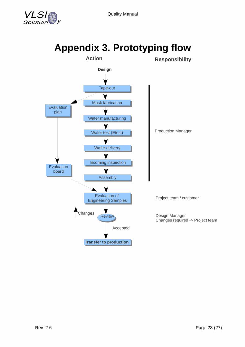
7.3.6. Prototyping
Release of the wafer mask database to the mask shop uses tapeout forms of the wafer manufacturer. Flow diagram of Prototyping phase is in Appendix 3.
Engineering samples of the product are done by using the same production equipment and package as the target final product.
Engineering samples are measured in the laboratory by using the Evaluation Board and results are compared with the target numbers of the Device Specification or Datasheet.
7.3.7. Transfer to Production
Transfer to production phase starts when Engineering samples indicate conforming to the specified functional and parametric test performance. Flow diagram of Transfer to Production phase is in Appendix 4.
Product Qualification is major task of Transfer to Production phase. It consists of three major subclasses: Package, Device and Process capability.
7.3.7.1. Package QualificationPackage qualification contains environmental, mechanical and electrical tests and moisture sensitivity level (MSL) classification.
7.3.7.2. Device qualificationThe device qualification is done for devices that have been fabricated with the production masks and encapsulated with the qualified production package. Each device has also passed the Final Test. The qualification contains following tests:
electrical temperature characterization: each device is tested by using the characterization test program in three temperatures and three operating voltage conditions. latch-up immunity: I-Test and Voltage testhigh temperature operating life test: +125 oC, 1000 h, device biased to maximum operating voltage and activity
7.3.7.3. Process capabilityProcess capability verification is based on test statistics of the corner processed wafers. Following tests are done
yield, analysis of wafer process cornersrepeatability test of a typical deviceCp and Cpk analysis of a typical process
When prototypes of a Product pass all qualifications then Qualification Report is written for the device, Revision 1.0 of the Datasheet is released and device status is changed as “Production”.
Rev. 2.6 Page 13 (27)
Quality Manual
7.3.8. Control of design and development changes
The design changes are reviewed and approved by the authorized personnel before implementation. The review includes evaluation of the effect of the changes on constituent parts and products already delivered.
Major changes of ASICs need customer approval and executed with approval of ECN or revised Device Specification. Minor changes of ASICs need only to be informed to the customer.
Major changes in ASSPs do not require approval from customer. Major changes can be done in the weekly meetings or project meetings and are recorded by the Project Manager. Project Manager can approve minor changes of ASSPs and they do not need to be recorded.
7.4. Purchasing
7.4.1. Purchasing process
The subcontractors used for manufacturing are selected with care. The wafer manufacturer, assembly and test subcontractors must have ISO 9001:2000 and ISO 14001 certifications preferably ISO/TS16949 as well. The subcontractors are audited before starting to use them for production. Audit results are recorded.
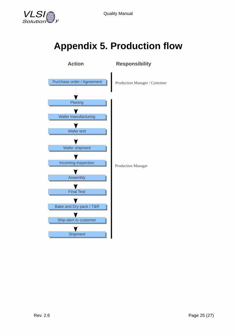
7.4.2. Purchasing information
The manufacturing is based on mutually agreed flows with subcontractors. VLSI uses standard flows of the subcontractors as much as possible. General flow diagram of Production phase is in Appendix 5. If there is a need for VLSI specific changes, these are documented into the subcontractor's system as a customer specific flow. The flows must be ready and approved before the subcontractor can start production.
The purchase order of a product includes device code that is used as key index to the agreed production flow. Flow diagrams of IC Product Order are in Appendixes 6 and 7.
7.4.3. Verification of purchased product
The production flows have quality gates. The device must pass the gate in order to proceed to the next step.
All products are final tested against Datasheet at the end of the manufacturing process. All test results of all devices are recorded and mirrored from the subcontractor to VLSI. Low yield of a product will stop the lot until test engineer of VLSI has given disposition.
The content of labels of inner boxes are checked by QA department of the subcontractor. Inner boxes that are quality passed are sealed with QA seal label.
The received materials are verified at VLSI by checking the device code and quantity. Also outer box condition is checked. The inner boxes are not opened if outer box has passed the verification in order to avoid unnecessary opening of the vacuum sealed moisture barrier bags.
Rev. 2.6 Page 14 (27)

Quality Manual
7.5. Production
7.5.1. Control of production
Production flow documents present the sequence of manufacturing steps for a specific product type. These documents provide the quality plan for controlling product fabrication, work instructions, equipment and records for each production lot. Subcontractors maintain and follow the production flows. General flow diagram of Production phase is in Appendix 5.
Test hardware and software is developed by Product/Test Engineering or by subcontracted suppliers. Product/Test Engineering qualify the initial setup by using production setup and correlation procedures.
Test subcontractors maintain test hardware. Test setups are qualified for each use by product specific self-test and calibration of the tester.
7.5.2. Validation of process for production
The validation of the process is part of the Transfer to Production phase of the development. The capability of the wafer process is validated by varying the process to extreme corners and analyzing the yield results. Assembly process is validated by Package Qualification (see 7.3.7) and analyzing the reliability data. The test flow is validated during Device Qualification by monitoring process capability per software bin and percentage of open/short fails.
7.5.3. Identification and traceability
The research and development is done in projects. Each project is named and the project name is used as a primary key for identification. The name can be any combination of letters and numbers. Preferred names are short and easy to remember. The list of active projects and Project Managers is available via intranet of VLSI. Once project is done it will be removed from the project list of the intranet.
When project is transferred to production, the product name will be created. For ASIC projects, the seed of the name comes from the customer, for ASSP projects the seed of the name is given by VLSI in the form VSXXXX where XXXX is number. The actual project name is obtained by adding major and minor version letters following the seed name.
Major change character is immediately following the seed name. The first version is A, the second is B, the third is C etc.
Minor change number is immediately following the major version character. The first version has no number, the second version has number 1, the third version has number 2 etc. For instance product VS1234 second major version third minor version has product name of VS1234B2. Product name excluding the minor version is marked on the package of the product, in the above example it is VS1234B.
The traceability of a product is based on lot number. The Lot number is given by wafer manufacturer. The lot number is written by laser on the wafer. This unique number is used through the entire production chain and finally marked on the package of the device.
The device name and lot number can be used to backtrack any detail of the manufacturing chain.
The package variants of the same ASSP project are distinguished by a hyphen mark that separates the above explained product name and package name. For instance the above example product VS1234B in LQFP48 package has complete product id of VS1234B-L. The
Rev. 2.6 Page 15 (27)

Quality Manual
package marking has optional second letter T that indicates if device is put on tape and reel. The above example in LQFP48 package and on tape and reel would has complete product id of VS1234B-LT.
Note that package and tape and reel option letters are not laser marked on the package.
For historical reasons (to separate non-RoHS and RoHS as well as Ink and laser marking) the products have second equivalent name that is used in the inner and outer carton boxes of the packing. This marking has no more meaning since all our existing products are RoHS compatible and marked with the laser but it can not be changed because it follows the quality system of the assembly and test subcontractor. Table below shows examples of major products to clarify the logic.
Project Package Packing Product Id Equivalent Product id that is used in the inner and outer carton boxes
VSXXXXZ LQFP48 Tray VSXXXXZ-L VSXXXXZ/LSR-ROHS
VSXXXXZ LQFP48 T&R VSXXXXZ-LT VSXXXXZ/LSR-ROHS/T
VSXXXXZ SOIC28 Tube VSXXXXZ-S VSXXXXZ-S/LSR-ROHS
VSXXXXZ SOIC28 T&R VSXXXXZ-ST VSXXXXZ-S/LSR-ROHS/TXXXX is project code, Z is major version, T&R means Tape and Reel.
The following table shows examples of real products.
Project Package Packing Product Id Equivalent Product id that is used in the inner and outer carton boxes
VS1011E LQFP48 Tray VS1011E-L VS1011E/LSR-ROHS
VS1011E LQFP48 T&R VS1011E-LT VS1011E/LSR-ROHS/T
VS1011E SOIC28 Tube VS1011E-S VS1011E-S/LSR-ROHS
VS1011E SOIC28 T&R VS1011E-ST VS1011E-S/LSR-ROHS/T
VS1003B LQFP48 Tray VS1003B-L VS1003B/LSR-ROHS
VS1033D LQFP48 Tray VS1033D-L VS1033D/LSR-ROHS
VS1053B LQFP48 Tray VS1053B-L VS1053B/LSR-ROHS
VS1063A LQFP48 Tray VS1063A-L VS1063A/LSR-ROHS
VS1000D LQFP48 Tray VS1000D-L VS1000D/LSR-ROHS
7.5.4. Customer property
Information is handled as agreed in the Non-Disclosure Agreement.
Other property, for example measuring equipment, prototypes, test systems and tools that are owned by customers or other parties:
Design or Product Managers are responsible to name persons to implementReceiving inspection. The owner shall be informed if the customer property does not work properly or if the product is damaged. Protect and safeguard the customer property. Notify the owner if the product is lost, damaged or if it is unsuitable for use. The decision of the actions to be taken are agreed together with the owner.
Rev. 2.6 Page 16 (27)
Quality Manual
7.5.5. Preservation of product
During the production phase preservation and delivery procedures are arranged by the subcontractors (see chapter 7.4. Purchasing) and by VLSI.
Preservation of products at premises of VLSI: Wafers and products are sensitive to ESD (Electro Static Discharge) and need a special handling and packaging. Packaging is performed by trained personnel in the ESD protected environment.Products are properly marked and stored separately, so that they can not be mixed to engineering samples or prototypes.
7.6. Control of monitoring and measuring devicesThe control of the manufacturing equipment is based on ISO 9001:2000 system of the subcontractor. For wafer and assembly subcontractors we require ISO 14001-2004 and ISO/TS 16949 certifications as well.
8. Measuring, analysis and improvement
8.1. GeneralMeasuring and analysis is needed to demonstrate the ability to achieve planned results. If the planned results are not achieved the actions are taken to ensure that the planned results will be achieved.
8.2. Monitoring and measurement
8.2.1. Customer satisfaction
VLSI collects following information to be summarized for management meeting:complaintsreturns from the customersdelivery performance
The summary to management meeting shall include a proposal of ranking what issues to improve.
8.2.2. Internal audit
Internal audits are scheduled once per year to assess each quality system process against the ISO9001:2000 standard at least once every 24 months.
Department managers are clients of the results for their audited activities.The order of importance for internal audits is:a) verify that quality system processes defined in the quality manual are in useb) verify that they conform to the requirements of the quality manualc) verify that quality system satisfies customer requirementsd) maintenance of the quality system processes and procedurese) verify that the quality manual processes meet ISO 9001:2000 requirements
The Quality Department maintains audit schedules and conducts internal audits using qualified internal and/or subcontracted auditors.
Rev. 2.6 Page 17 (27)
Quality Manual
Managers of audited departments are responsible for taking appropriate actions within an agreed time frame. Managers report action follow-up to the Quality Department.
The Quality Department is responsible for follow-up to verify the action is implemented and effective. Verification results are part of the internal audit record.
The Quality department is responsible to summarize internal audit results and present them for management review.
Internal audit records are originated by the Quality Department and maintained in Document Control.
8.2.3. Monitoring and measurement of processes
VLSI keeps scorecards for each active subcontractor. Scoring information collects delivery, quality and reliability performance and trends of all products of the subcontractor.
8.2.4. Monitoring and measurement of product
Yield average and variance serve as the top quality objectives for product conformity.
Product/Test Engineering reports the average and variance of the yield per product for internal audit and management review. Product/Test Engineering also reports the major bin and frequency of lots that have been put on hold.
Product/Test Engineering will initiate proposal for improvement in case that yield variance is abnormal highaverage yield is significantly below the expected yieldlot hold frequency is exceptionally high
Quality department monitors the number of returned products and reports them for internal audit and management review. Quality department will initiate internal corrective action in case product does not have decreasing trend of returns.
8.3. Control of nonconforming productYield limits are the primary control of nonconformities. They are used as lot acceptance criteria during test/inspection steps during final test operations.
After detection of a failing lot, the test setup is then verified by using correlation devices. If there is nothing wrong in the test setup and correlation devices pass the test, then the lot is put on hold for engineering notification and disposition.
Product/Test Engineering is responsible to determine the cause and disposition.
The options for Test Engineering disposition are:a) correct and qualify the test setup and repeat the testb) confirm the reliability of passing units and let the low yield low to proceedc) screen the product to eliminate a specific nonconformity from the population of units, then proceedd) scrap the lot or otherwise prevent the use of the lot.
8.4. Analysis of dataFollowing data is summarized for the annual management review:
customer satisfaction
Rev. 2.6 Page 18 (27)

Quality Manual
conformity to product requirementscharacteristics and trends of the processesmajor subcontractor strengths and weaknesses related to product price, performance, power consumption and package.
8.5. Improvement
8.5.1. Continual improvement
The organization will continually improve the effectiveness of the quality system through the use of the quality policy, quality objectives, audit results, analysis of data, corrective and preventive actions and management reviews.
8.5.2. Corrective action
The purpose of the corrective action is to revise or replace process so that it will produce conforming products.
Information that triggers corrective action includes audits, management reviews, returned material authorization (RMA), and failure analysis (FA) requests.
Customer complaint is reviewed when received by the Quality Manager. If the complaint is valid, Quality Manager will assign person or team to do failure analysis (FA). Objective of FA is to determine the root cause. Based on the FA, the team will prepare 8D report and actions to be made are decided. The project is reviewed after the actions have been made. The Quality Manager will decide is there a need to update the 8D report, were the actions sufficient and can the case be closed.
Contents of 8D report:1. Team formation2. Problem description3. Implementation & verify interim containment action4. Define and verify root cause5. Choose and verify permanent corrective actions6. Implement/verify permanent corrective actions7. Prevent recurrence & systemic preventive recommendation(s)8. Thanks to the team
The quality department will store the 8D reports. The quality department reports summary of the corrective actions for Management Review
8.5.3. Preventive action
The purpose of preventive action is to improve manufacturability and conformance of products and processes. Preventive action is needed when potential nonconformity frequency is high, ability to detect is low, and effect is strong.
Once the risk for preventive action is known and a decision for preventive action is made, an individual or team is assigned to define and implement the preventive action. After that the preventive action is administered in exactly the same way as the corrective action.
Any formal problem solving or analysis approach may be used to identify potential nonconformities and determine the need for preventive action. Regardless of the approach used, records should be generated that compare potential nonconformities with their root causes.
Rev. 2.6 Page 19 (27)
Quality Manual
Design project teams are responsible to implement preventive actions to products under development. Project Managers ensure that this is part of the project agenda.
Production Manager is responsible for ensuring that subcontractors accept the preventive actions for manufacturing processes.
Rev. 2.6 Page 20 (27)

Quality Manual
Appendix 1. New ASIC project flow
Rev. 2.6 Page 21 (27)
Project start
Action Responsibility
Design Manager / customerSales and Marketing ManagerReview by President
Technical InformationMarket analysis
Technical InformationMarket analysis
Pre-project / researchPre-project / research
YES
DesignDesign
NO
Customer contact
Additional information needed
Pre-project / Research
Action Responsibility
Design Manager / customerReview by President
QuotationQuotation
Research Research
Conclusions and Device Specification (pre)
Conclusions and Device Specification (pre)
DesignDesign
Purchase order / agreementPurchase order / agreement
Project teamReview by Project Manager

Quality Manual
Appendix 2. Design flow
Rev. 2.6 Page 22 (27)
Action Responsibility
Design Manager / customerReview by President
QuotationQuotation
Project planProject plan
Device SpecificationSystem design
Device SpecificationSystem design
Design of critical blocks
Design of critical blocks
Tape-out documentsAssembly documents
Preliminary Test Specification
Tape-out documentsAssembly documents
Preliminary Test Specification
PrototypingPrototyping
Purchase order / agreementPurchase order / agreement
Design Manager
Project team
Design Manager
Project Manager
DR1
Accepted
DR2Changes
Analog designDigital design
Software design
Analog designDigital design
Software design
Accepted
DR3Changes
Design ManagerChanges required -> Project team
Design Manager / Production ManagerChanges required -> Project team
VerificationsVerifications
Project team
Quality Manual
Appendix 3. Prototyping flow
Rev. 2.6 Page 23 (27)
Action Responsibility
Design
Mask fabricationMask fabrication
Evaluation of Engineering Samples
Evaluation of Engineering Samples
Transfer to productionTransfer to production
Tape-outTape-out
Production Manager
Accepted
ReviewChanges
Design ManagerChanges required -> Project team
Evaluationplan
Evaluationplan
Wafer manufacturingWafer manufacturing
Incoming inspectionIncoming inspection
Project team / customer
Evaluation board
Evaluation board
AssemblyAssembly
Wafer test (Etest)Wafer test (Etest)
Wafer deliveryWafer delivery

Quality Manual
Appendix 4. Transfer to production flow
Rev. 2.6 Page 24 (27)
Action Responsibility
Prototypes to customer
Prototypes to customer
ProductionProduction
Purchase order / agreementPurchase order / agreement
Design Manager
Test debugTest debug
Final Test Final Test
Accepted
DR4Changes Design Manager / Production Manager
Changes required -> Project team
Changes
QualificationQualification
QuotationQuotationDesign Manager / customerReview by President
Test hardware + softwareTest hardware + software
Test SpecificationTest Specification
ReportReport FeedbackFeedback
Quality Manual
Appendix 5. Production flow
Rev. 2.6 Page 25 (27)
Action Responsibility
Production Manager / CustomerPurchase order / AgreementPurchase order / Agreement
PlaningPlaning
Wafer manufacturingWafer manufacturing
Wafer shipmentWafer shipment
AssemblyAssembly
Final TestFinal Test
Bake and Dry pack / T&RBake and Dry pack / T&R
Ship-alert to customerShip-alert to customer
ShipmentShipment
Production Manager
Wafer testWafer test
Incoming inspectionIncoming inspection
Quality Manual
Appendix 6. PO review flow
Rev. 2.6 Page 26 (27)
Action Responsibility
New customerNew customer
YESQuotation /
Purchase order form
Quotation /Purchase order form
Review and approval
Review and approval
Customer approvalCustomer approval
Valid agreement that covers the
order
Valid agreement that covers the
order
Approved Purchase Order
Approved Purchase Order
Sales and Marketing Manager
Other than List Prices-> Review by Production Manager and PresidentSchedule of high volume orders-> Review by Production ManagerChanges required -> Sales and Marketing Manager
NO
Customer contactCustomer contact
Old customerOld customer
Sales Assistant / Sales and Marketing Manager
Changes
Changes
Quality Manual
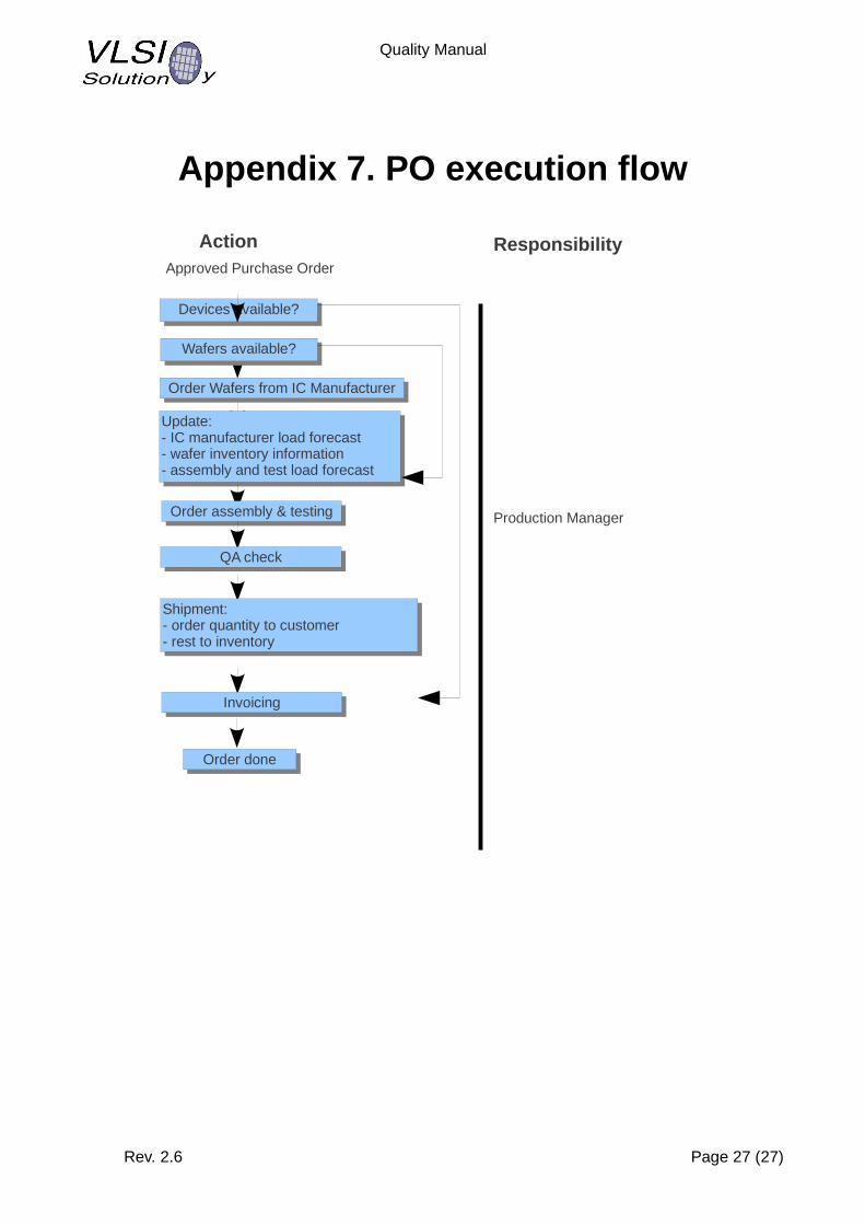
Appendix 7. PO execution flow
Rev. 2.6 Page 27 (27)
Action Responsibility
Devices available?Devices available?
Order Wafers from IC ManufacturerOrder Wafers from IC Manufacturer
Update:- IC manufacturer load forecast- wafer inventory information- assembly and test load forecast
Update:- IC manufacturer load forecast- wafer inventory information- assembly and test load forecast
Order assembly & testingOrder assembly & testing
QA checkQA check
Shipment:- order quantity to customer- rest to inventory
Shipment:- order quantity to customer- rest to inventory
InvoicingInvoicing
Order doneOrder done
Approved Purchase Order
Wafers available?Wafers available?
Production Manager