qsg ds-76xxni-i2^xp 032717na · .1%#. #%6+8#6+10 5[uvgo ceeguu tgswktgu c ugewtg wugt cuukipgf...
TRANSCRIPT
DS-76xxNI-I2/xP NVR Quick Start Guide (QSG) © 2017 Hikvision USA Inc. • All Rights Reserved • Any and all information, including, among others, wordings, pictures, and graphs are the properties of Hangzhou Hikvision Digital Technology Co., Ltd., or its subsidiaries (hereinafter referred to as “Hikvision”).
This user manual (hereinafter referred to as “the Manual”) cannot be reproduced, changed, translated, or distributed, partially or wholly, by any means, without the prior written permission of Hikvision. Unless otherwise stipulated, Hikvision does not make any warranties, guarantees, or representations, express or implied, regarding the Manual.
About this Manual: The Manual includes instructions for using and managing the product. Pictures, charts, images, and all other information hereinafter are for description and explanation only. The information contained in the Manual is subject to change, without notice, due to firmware updates or other reasons. Please find the latest version on the company Website (http://www.hikvision.com/us). Please use this user manual under the guidance of professionals.
Trademarks Acknowledgement: and other Hikvision trademarks and logos are the properties of Hikvision in various jurisdictions. Other trademarks and logos mentioned below are the properties of their respective owners.
Legal Disclaimer: TO THE MAXIMUM EXTENT PERMITTED BY APPLICABLE LAW, THE PRODUCT DESCRIBED, WITH ITS HARDWARE, SOFTWARE, AND FIRMWARE, IS PROVIDED “AS IS,” WITH ALL FAULTS AND ERRORS, AND HIKVISION MAKES NO WARRANTIES, EXPRESS OR IMPLIED, INCLUDING WITHOUT LIMITATION, MERCHANTABILITY, SATISFACTORY QUALITY, FITNESS FOR A PARTICULAR PURPOSE, AND NON-INFRINGEMENT OF THIRD PARTY. IN NO EVENT WILL HIKVISION, ITS DIRECTORS, OFFICERS, EMPLOYEES, OR AGENTS BE LIABLE TO YOU FOR ANY SPECIAL, CONSEQUENTIAL, INCIDENTAL, OR INDIRECT DAMAGES, INCLUDING, AMONG OTHERS, DAMAGES FOR LOSS OF BUSINESS PROFITS, BUSINESS INTERRUPTION, OR LOSS OF DATA OR DOCUMENTATION, IN CONNECTION WITH THE USE OF THIS PRODUCT, EVEN IF HIKVISION HAS BEEN ADVISED OF THE POSSIBILITY OF SUCH DAMAGES.
REGARDING TO THE PRODUCT WITH INTERNET ACCESS, THE USE OF PRODUCT SHALL BE WHOLLY AT YOUR OWN RISKS. HIKVISION SHALL NOT TAKE ANY RESPONSIBILITIES FOR ABNORMAL OPERATION, PRIVACY LEAKAGE, OR OTHER DAMAGES RESULTING FROM CYBER ATTACK, HACKER ATTACK, VIRUS INSPECTION, OR OTHER INTERNET SECURITY RISKS; HOWEVER, HIKVISION WILL PROVIDE TIMELY TECHNICAL SUPPORT IF REQUIRED.
SURVEILLANCE LAWS VARY BY JURISDICTION. CHECK ALL RELEVANT LAWS IN YOUR JURISDICTION BEFORE USING THIS PRODUCT IN ORDER TO ENSURE THAT YOUR USE CONFORMS TO THE APPLICABLE LAW. HIKVISION SHALL NOT BE LIABLE IN THE EVENT THAT THIS PRODUCT IS USED FOR ILLEGITIMATE PURPOSES.
IN THE EVENT OF ANY CONFLICTS BETWEEN THIS MANUAL AND THE APPLICABLE LAW, THE LATER PREVAILS.
Regulatory Information
FCC Information
FCC Compliance: This equipment has been tested and found to comply with the limits for a digital device, pursuant to part 15 of the FCC Rules. These limits are designed to provide reasonable protection against harmful interference when the equipment is operated in a commercial environment. This equipment generates, uses, and can radiate radio frequency energy and, if not installed and used in accordance with the instruction manual, may cause harmful interference to radio communications. Operation of this equipment in a residential area is likely to cause harmful interference in which case the user will be required to correct the interference at his own expense.
FCC Conditions: This device complies with part 15 of the FCC Rules. Operation is subject to the following two conditions:
1. This device may not cause harmful interference. 2. This device must accept any interference received, including interference that may cause undesired operation.
EU Conformity Statement
This product and, if applicable, the supplied accessories too are marked with “CE” and comply therefore with the applicable harmonized European standards listed under the EMC Directive 2004/108/EC, the RoHS Directive 2011/65/EU.
2012/19/EU (WEEE Directive): Products marked with this symbol cannot be disposed of as unsorted municipal waste in the European Union. For proper recycling, return this product to your local supplier upon the purchase of equivalent new equipment, or dispose of it at designated collection points. For more information see: www.recyclethis.info
2006/66/EC (battery directive): This product contains a battery that cannot be disposed of as unsorted municipal waste in the European Union. See the product documentation for specific battery information. The battery is marked with this symbol, which may include lettering to indicate cadmium (Cd), lead (Pb), or mercury (Hg). For proper recycling, return the battery to your supplier or to a designated collection point. For more information see: www.recyclethis.info.
Industry Canada ICES-003 Compliance: This device meets the CAN ICES-3 (A)/NMB-3(A) standards requirements.
Safety Instruction: These instructions are intended to ensure that the user can use the product correctly to avoid danger or property loss. The precaution measure is divided into “Warnings” and “Cautions.” • Warnings: Serious injury or death may occur if any of the warnings are neglected. • Cautions: Injury or equipment damage may occur if any of the cautions are neglected.
Warnings Follow these safeguards to prevent serious injury or death. Cautions Follow these precautions to prevent potential injury or material damage.
Warnings • Proper configuration of all passwords and other security settings is the responsibility of the installer and/or end-user. • In the use of the product, you must be in strict compliance with the electrical safety regulations of the nation and region. Refer to technical specifications for detailed information. • Input voltage should meet both the SELV (Safety Extra Low Voltage) and the Limited Power Source with 24 VAC or 12 VDC according to the IEC60950-1 standard. Refer to
technical specifications for detailed information. • Do not connect several devices to one power adapter as adapter overload may cause over-heating or a fire hazard. • Make sure that the plug is firmly connected to the power socket. When the product is mounted on wall or ceiling, the device shall be firmly fixed. • If smoke, odor, or noise rise from the device, turn off the power at once and unplug the power cable, and then contact the service center.
Cautions • Make sure the power supply voltage is correct before using the device. • Do not drop the device or subject it to physical shock. • If cleaning is necessary, use clean cloth with a bit of ethanol and wipe it gently. If the device will not be used for an extended period, protect it from dirt. • Do not place the device in extremely hot, cold, dusty, or damp locations, and do not expose it to high electromagnetic radiation. Do not operate product in outside of its stated
environmental specs. • To avoid heat accumulation, good ventilation is required for the operating environment. • Keep the device away from liquids while in use. • While in delivery, the device shall be packed in its original packing, or packing of the same durability. • Regular part replacement: some equipment parts (e.g., electrolytic capacitor) shall be replaced regularly according to their average endurance time. The average time varies
because of differences between operating environments and usage history, so regular checking is recommended for all users. Contact your dealer for more details. • Improper use or replacement of the battery may result in hazard of explosion. Replace with the same or equivalent type only. Dispose of used batteries according to the
instructions provided by the battery manufacturer. • If the product does not work properly, contact your dealer or the nearest service center. Never attempt to disassemble the device yourself. (We shall not assume any
responsibility for problems caused by unauthorized repair or maintenance.)
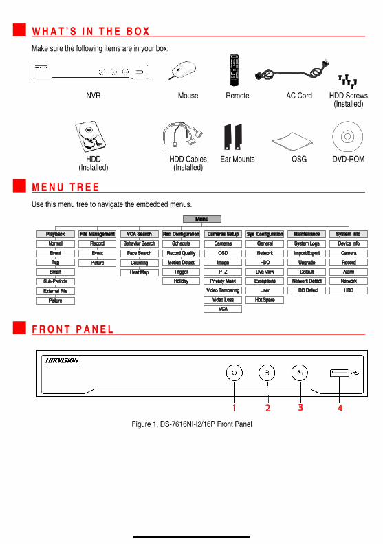
W H A T ’ S I N T H E B O X Make sure the following items are in your box:
NVR Mouse Remote AC Cord HDD Screws (Installed)
HDD HDD Cables Ear Mounts QSG DVD-ROM (Installed) (Installed)
M E N U T R E E Use this menu tree to navigate the embedded menus.
F R O N T P A N E L
Figure 1, DS-7616NI-I2/16P Front Panel
F R O N T P A N E L ( c o n t i n u e d )
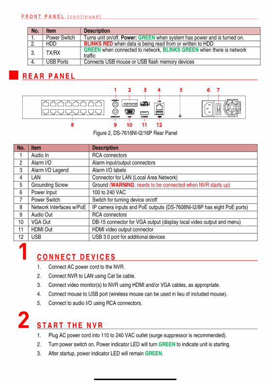
No. Item Description 1. Power Switch Turns unit on/off. Power: GREEN when system has power and is turned on. 2. HDD BLINKS RED when data is being read from or written to HDD
3. TX/RX GREEN when connected to network, BLINKS GREEN when there is network traffic
4. USB Ports Connects USB mouse or USB flash memory devices
R E A R P A N E L
Figure 2, DS-7616NI-I2/16P Rear Panel
No. Item Description 1 Audio In RCA connectors 2 Alarm I/O Alarm input/output connectors 3 Alarm I/O Legend Alarm I/O labels 4 LAN Connector for LAN (Local Area Network) 5 Grounding Screw Ground (WARNING: needs to be connected when NVR starts up) 6 Power Input 100 to 240 VAC 7 Power Switch Switch for turning device on/off 8 Network Interfaces w/PoE IP camera inputs and PoE outputs (DS-7608NI-I2/8P has eight PoE ports) 9 Audio Out RCA connectors 10 VGA Out DB-15 connector for VGA output (display local video output and menu) 11 HDMI Out HDMI video output connector 12 USB USB 3.0 port for additional devices
1 C O N N E C T D E V I C E S 1. Connect AC power cord to the NVR.
2. Connect NVR to LAN using Cat 5e cable.
3. Connect video monitor(s) to NVR using HDMI and/or VGA cables, as appropriate.
4. Connect mouse to USB port (wireless mouse can be used in lieu of included mouse).
5. Connect to audio I/O using RCA connectors.
2 S T A R T T H E N V R 1. Plug AC power cord into 110 to 240 VAC outlet (surge suppressor is recommended).
2. Turn power switch on. Power indicator LED will turn GREEN to indicate unit is starting.
3. After startup, power indicator LED will remain GREEN.
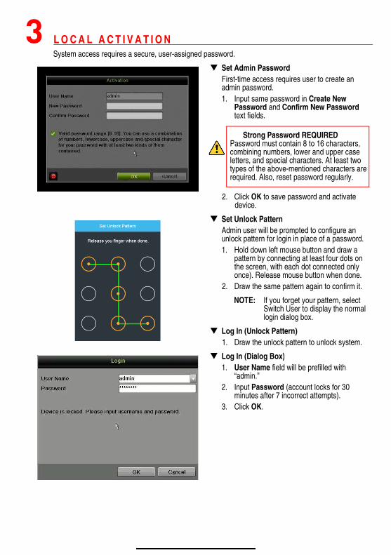
3 L O C A L A C T I V A T I O N System access requires a secure, user-assigned password.
Set Admin Password First-time access requires user to create an admin password. 1. Input same password in Create New
Password and Confirm New Password text fields.
Strong Password REQUIRED Password must contain 8 to 16 characters, combining numbers, lower and upper case letters, and special characters. At least two types of the above-mentioned characters are required. Also, reset password regularly.
2. Click OK to save password and activate device.
Set Unlock Pattern Admin user will be prompted to configure an unlock pattern for login in place of a password. 1. Hold down left mouse button and draw a
pattern by connecting at least four dots on the screen, with each dot connected only once). Release mouse button when done.
2. Draw the same pattern again to confirm it.
NOTE: If you forget your pattern, select Switch User to display the normal login dialog box.
Log In (Unlock Pattern) 1. Draw the unlock pattern to unlock system.
Log In (Dialog Box) 1. User Name field will be prefilled with
“admin.” 2. Input Password (account locks for 30
minutes after 7 incorrect attempts). 3. Click OK.
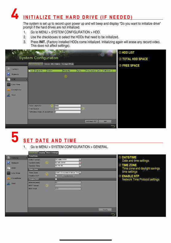
4 I N I T I A L I Z E T H E H A R D D R I V E ( I F N E E D E D ) The system is set up to record upon power up and will beep and display “Do you want to initialize drive” prompt if the hard drives are not initialized. 1. Go to MENU > SYSTEM CONFIGURATION > HDD. 2. Use the checkboxes to select the HDDs that need to be initialized. 3. Press INIT. (Factory installed HDDs come initialized. Initializing again will erase any record video.
This does not affect settings).
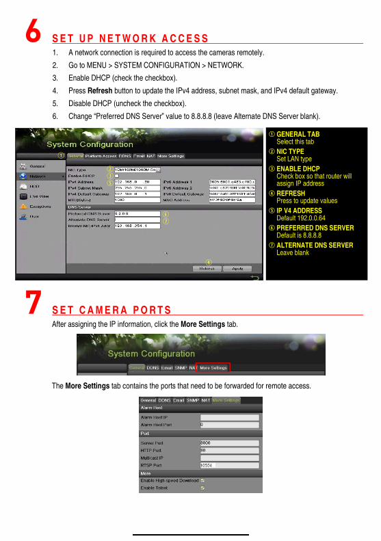
5 S E T D A T E A N D T I M E 1. Go to MENU > SYSTEM CONFIGURATION > GENERAL.
DATE/TIMEDate and time settings
TIME ZONE Time zone and daylight savings time settings
ENABLE NTP Network Time Protocol settings
HDD LIST TOTAL HDD SPACE FREE SPACE
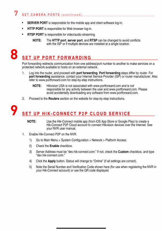
6 S E T U P N E T W O R K A C C E S S 1. A network connection is required to access the cameras remotely.
2. Go to MENU > SYSTEM CONFIGURATION > NETWORK.
3. Enable DHCP (check the checkbox).
4. Press Refresh button to update the IPv4 address, subnet mask, and IPv4 default gateway.
5. Disable DHCP (uncheck the checkbox).
6. Change “Preferred DNS Server” value to 8.8.8.8 (leave Alternate DNS Server blank).
7 S E T C A M E R A P O R T S After assigning the IP information, click the More Settings tab.
The More Settings tab contains the ports that need to be forwarded for remote access.
GENERAL TAB Select this tab
NIC TYPE Set LAN type
ENABLE DHCP Check box so that router will assign IP address
REFRESH Press to update values
IP V4 ADDRESS Default 192.0.0.64
PREFERRED DNS SERVER Default is 8.8.8.8
ALTERNATE DNS SERVER Leave blank
7 S E T C A M E R A P O R T S ( c o n t i n u e d )
• SERVER PORT is responsible for the mobile app and client software log-in.
• HTTP PORT is responsible for Web browser log-in.
• RTSP PORT is responsible for video/audio streaming.
NOTE: The HTTP port, server port, and RTSP can be changed to avoid conflicts with the ISP or if multiple devices are installed at a single location.
8 S E T U P P O R T F O R W A R D I N G Port forwarding redirects communication from one address/port number to another to make services on a protected network available to hosts on an external network.
1. Log into the router, and proceed with port forwarding. Port forwarding steps differ by router. For port forwarding assistance, contact your Internet Service Provider (ISP) or router manufacturer. Also refer to www.portforward.com for step-by-step instructions.
NOTE: Hikvision USA is not associated with www.portforward.com and is not responsible for any activity between the user and www.portforward.com. Please avoid accidentally downloading any software from www.portforward.com.
2. Proceed to the Routers section on the website for step-by-step instructions.
9 S E T U P H I K - C O N N E C T P 2 P C L O U D S E R V I C E
NOTE: Use the Hik-Connect mobile app (from iOS App Store or Google Play) to create a Hik-Connect P2P Cloud account to connect Hikvision devices over the Internet. See your NVR user manual.
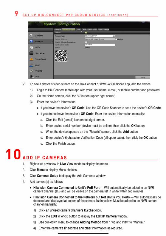
1. Enable Hik-Connect P2P on the NVR.
1) Go to Main Menu > System Configuration > Network > Platform Access.
2) Check the Enable checkbox.
3) Server Address must be “dev.hik-connect.com.” If not, check the Custom checkbox, and type “dev.hik-connect.com.”
4) Click the Apply button. Status will change to “Online” (if all settings are correct).
5) Note the Serial Number and Verification Code shown here (for use when registering the NVR in your Hik-Connect account) or use the QR code displayed.
9 S E T U P H I K - C O N N E C T P 2 P C L O U D S E R V I C E ( c o n t i n u e d )
2. To see a device’s video stream on the Hik-Connect or iVMS-4500 mobile app, add the device.
1) Login to Hik-Connect mobile app with your user name, e-mail, or mobile number and password.
2) On the Home screen, click the “+” button (upper right corner).
3) Enter the device’s information.
If you have the device’s QR Code: Use the QR Code Scanner to scan the device’s QR Code.
If you do not have the device’s QR Code: Enter the device information manually:
a. Click the Edit (pencil) icon on top right corner.
b. Enter device serial number (device must be online), then click the OK button.
c. When the device appears on the “Results” screen, click the Add button.
d. Enter device’s 6-character Verification Code (all upper case), then click the OK button.
e. Click the Finish button.
10 A D D I P C A M E R A S 1. Right click a window in Live View mode to display the menu.
2. Click Menu to display Menu choices.
3. Click Cameras Setup to display the Add Cameras window.
4. Add camera(s) as follows:
Hikvision Camera Connected to Unit’s PoE Port — Will automatically be added to an NVR camera channel (Dx) and will be visible on the camera list in white within two minutes.
Hikvision Camera Connected to the Network but Not Unit’s PoE Ports — Will automatically be detected and displayed at bottom of the camera list in yellow. Must be added to an NVR camera channel manually:
1) Click an unused camera channel’s Dx checkbox.
2) Click the EDIT (Pencil) button to display the Edit IP Camera window.
3) Use pull-down menu to change Adding Method from “Plug and Play” to “Manual.”
4) Enter the camera’s IP address and other information as required.
10 A D D I P C A M E R A S ( c o n t i n u e d )
5) Press the OK button to add the camera.
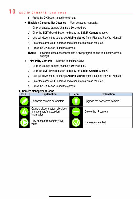
Hikvision Cameras Not Detected — Must be added manually:
1) Click an unused camera channel’s Dx checkbox.
2) Click the EDIT (Pencil) button to display the Edit IP Camera window.
3) Use pull-down menu to change Adding Method from “Plug and Play” to “Manual.”
4) Enter the camera’s IP address and other information as required.
5) Press the OK button to add the camera.
NOTE: If camera does not connect, use SADP program to find and modify camera settings.
Third-Party Cameras — Must be added manually:
1) Click an unused camera channel’s Dx checkbox.
2) Click the EDIT (Pencil) button to display the Edit IP Camera window.
3) Use pull-down menu to change Adding Method from “Plug and Play” to “Manual.”
4) Enter the camera’s IP address and other information as required.
5) Press the OK button to add the camera.
IP Camera Management Icons Icon Explanation Icon Explanation
Edit basic camera parameters
Upgrade the connected camera
Camera disconnected; click icon to get camera’s exception information
Delete the IP camera
Play connected camera’s live video
Camera connected
10 A D D I P C A M E R A S ( c o n t i n u e d )
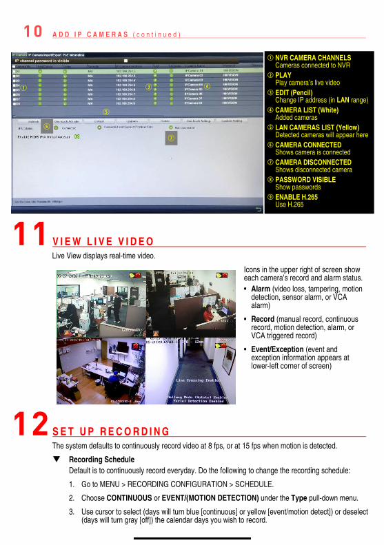
11 V I E W L I V E V I D E O Live View displays real-time video.
12 S E T U P R E C O R D I N G The system defaults to continuously record video at 8 fps, or at 15 fps when motion is detected.
Recording Schedule Default is to continuously record everyday. Do the following to change the recording schedule:
1. Go to MENU > RECORDING CONFIGURATION > SCHEDULE.
2. Choose CONTINUOUS or EVENT/(MOTION DETECTION) under the Type pull-down menu.
3. Use cursor to select (days will turn blue [continuous] or yellow [event/motion detect]) or deselect (days will turn gray [off]) the calendar days you wish to record.
Icons in the upper right of screen show each camera’s record and alarm status. • Alarm (video loss, tampering, motion
detection, sensor alarm, or VCA alarm)
• Record (manual record, continuous record, motion detection, alarm, or VCA triggered record)
• Event/Exception (event and exception information appears at lower-left corner of screen)
NVR CAMERA CHANNELS Cameras connected to NVR
PLAY Play camera’s live video
EDIT (Pencil) Change IP address (in LAN range)
CAMERA LIST (White) Added cameras
LAN CAMERAS LIST (Yellow) Detected cameras will appear here
CAMERA CONNECTED Shows camera is connected
CAMERA DISCONNECTED Shows disconnected camera
PASSWORD VISIBLE Show passwords
ENABLE H.265 Use H.265
12 S E T U P R E C O R D I N G ( c o n t i n u e d )
4. Apply time settings as desired.
5. Press APPLY.
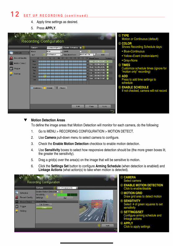
Motion Detection Areas
To define the image areas that Motion Detection will monitor for each camera, do the following:
1. Go to MENU > RECORDING CONFIGURATION > MOTION DETECT.
2. Use Camera pull-down menu to select camera to configure.
3. Check the Enable Motion Detection checkbox to enable motion detection.
4. Use Sensitivity boxes to select how responsive detection should be (the more green boxes lit, the greater the sensitivity).
5. Drag a grid(s) over the area(s) on the image that will be sensitive to motion.
6. Click the Settings Set button to configure Arming Schedule (when detection is enabled) and Linkage Actions (what action(s) to take when motion is detected).
CAMERA Select camera
ENABLE MOTION DETECTION Click to enable/disable
MOTION GRID Draw grid area to detect motion
SENSITIVITY Select# of green squares to set sensitivity
SETTINGS/SET Configure arming schedule and
linkage actionsAPPLY
Click to apply settings
TYPE Motion or Continuous (default)
COLOR Shows Recording Schedule days: • Blue=Continuous • Yellow=Event (motion/alarm) • Grey=None
TIMES Customize schedule times (ignore for
“motion only” recording) ADD Press to add time settings to
schedule ENABLE SCHEDULE
If not checked, camera will not record
12 S E T U P R E C O R D I N G ( c o n t i n u e d )
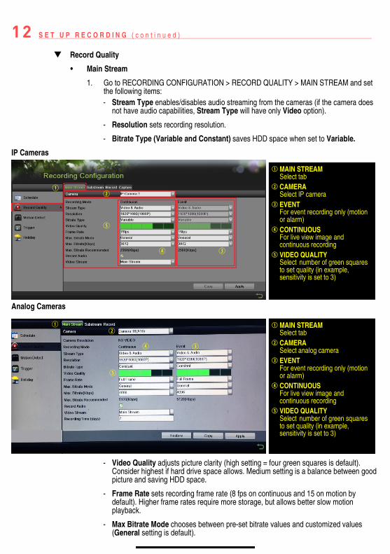
Record Quality
• Main Stream
1. Go to RECORDING CONFIGURATION > RECORD QUALITY > MAIN STREAM and set the following items: - Stream Type enables/disables audio streaming from the cameras (if the camera does
not have audio capabilities, Stream Type will have only Video option).
- Resolution sets recording resolution.
- Bitrate Type (Variable and Constant) saves HDD space when set to Variable.
IP Cameras
Analog Cameras
- Video Quality adjusts picture clarity (high setting = four green squares is default).
Consider highest if hard drive space allows. Medium setting is a balance between good picture and saving HDD space.
- Frame Rate sets recording frame rate (8 fps on continuous and 15 on motion by default). Higher frame rates require more storage, but allows better slow motion playback.
- Max Bitrate Mode chooses between pre-set bitrate values and customized values (General setting is default).
MAIN STREAM Select tab
CAMERA Select IP camera
EVENTFor event recording only (motion or alarm)
CONTINUOUSFor live view image and continuous recording
VIDEO QUALITY Selectnumber of green squares to set quality (in example, sensitivity is set to 3)
MAIN STREAM Select tab
CAMERA Select analog camera
EVENTFor event recording only (motion or alarm)
CONTINUOUSFor live view image and continuous recording
VIDEO QUALITY Selectnumber of green squares to set quality (in example, sensitivity is set to 3)

12 S E T U P R E C O R D I N G ( c o n t i n u e d )
- Max Bitrate (kbps) is the chosen bitrate for streaming the video. Max Bitrate should be adjusted to meet or exceed the rate recommended by the system for the chosen parameters.
- Max Bitrate Recommended is impacted by resolution, quality, and framerate.
- Record Audio turns on audio recording (requires external mic or camera w/built in mic.
- Video Stream determines which stream is recorded. Leave at default (Main Stream).
• Substream
1. Go to RECORDING CONFIGURATION > RECORD QUALITY > SUBSTREAM to set up the Sub Stream to stream to mobile devices and display multiple cameras locally.
NOTE: If the upload speed is not sufficient, lower the frame rate, bitrate, and or resolution for more fluent mobile viewing.
13 P L A Y B A C K R E C O R D E D V I D E O 1. Go to MENU > PLAYBACK.
2. Select the desired camera(s) from the menu on the right of the screen.
3. Select date (days w/recordings will be blue if continuous only or yellow if all/part of day was event).
4. Press PLAY.
5. Click within the timeline to jump to desired time.
PLAYBACK TYPE MENU Select type of record to play
FULL SCREEN Goes to full screen for multiple channel playback
PLAY/STOP Begin playback (toggles between Play and Stop)
CAMERA LIST Select camera(s) to play back
CALENDAR Select date to play back
TIMELINE Click on timeline to jump to desired playback time
SUBSTREAM TAB Select
CAMERA Select camera
STREAM TYPE Select choice
RESOLUTION Can go up only to 4CIF
VIDEO QUALITY Select number of green squares to set quality (in example, sensitivity is set to 3)
13 P L A Y B A C K R E C O R D E D V I D E O ( c o n t i n u e d )
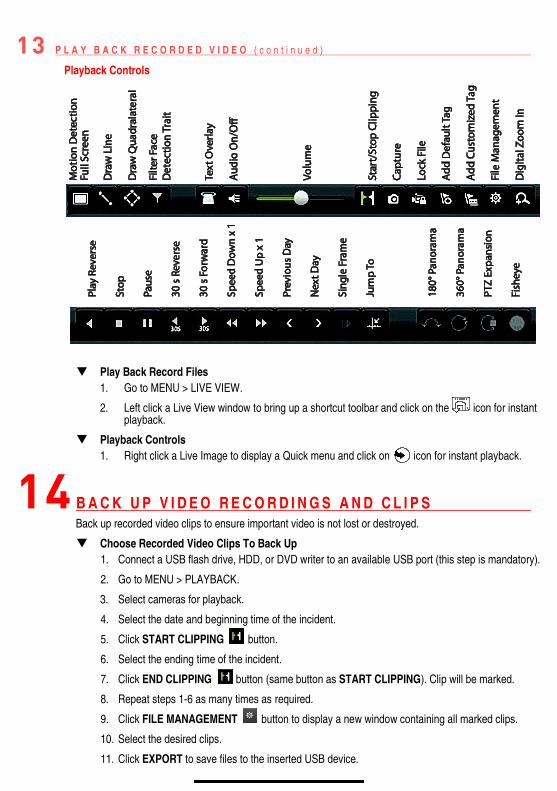
Playback Controls
Play Back Record Files 1. Go to MENU > LIVE VIEW.
2. Left click a Live View window to bring up a shortcut toolbar and click on the icon for instant playback.
Playback Controls 1. Right click a Live Image to display a Quick menu and click on icon for instant playback.
14 B A C K U P V I D E O R E C O R D I N G S A N D C L I P S Back up recorded video clips to ensure important video is not lost or destroyed.
Choose Recorded Video Clips To Back Up 1. Connect a USB flash drive, HDD, or DVD writer to an available USB port (this step is mandatory).
2. Go to MENU > PLAYBACK.
3. Select cameras for playback.
4. Select the date and beginning time of the incident.
5. Click START CLIPPING button.
6. Select the ending time of the incident.
7. Click END CLIPPING button (same button as START CLIPPING). Clip will be marked.
8. Repeat steps 1-6 as many times as required.
9. Click FILE MANAGEMENT button to display a new window containing all marked clips.
10. Select the desired clips.
11. Click EXPORT to save files to the inserted USB device.
14 B A C K U P R E C O R D E D ( c o n t i n u e d )
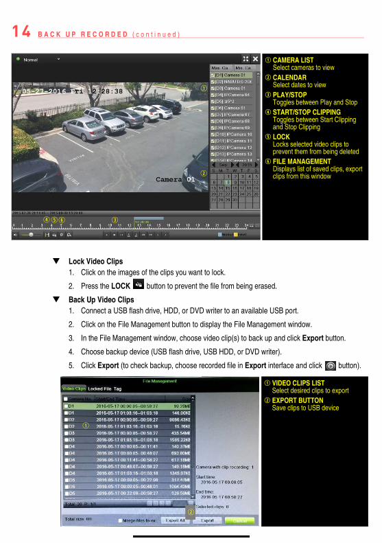
Lock Video Clips
1. Click on the images of the clips you want to lock.
2. Press the LOCK button to prevent the file from being erased.
Back Up Video Clips 1. Connect a USB flash drive, HDD, or DVD writer to an available USB port.
2. Click on the File Management button to display the File Management window.
3. In the File Management window, choose video clip(s) to back up and click Export button.
4. Choose backup device (USB flash drive, USB HDD, or DVD writer).
5. Click Export (to check backup, choose recorded file in Export interface and click button).
CAMERA LIST Select cameras to view
CALENDAR Select dates to view
PLAY/STOP Toggles between Play and Stop
START/STOP CLIPPING Toggles between Start Clipping and Stop Clipping
LOCK Locks selected video clips to prevent them from being deleted
FILE MANAGEMENT Displays list of saved clips, export clips from this window
VIDEO CLIPS LIST Select desired clips to export
EXPORT BUTTON Save clips to USB device

Hikvision USA Inc., 18639 Railroad Street, City of Industry, CA 91748, USA Hikvision Canada, 4485 Dobrin, St-Laurent, Quebec, Canada, H4R 2L8 Telephone: +1-909-895-0400 • Toll Free in USA: +1-866-200-6690 E-Mail: [email protected] • www.hikvision.com © 2017 Hikvision USA Inc. • All Rights Reserved
Specifications subject to change without notice. QSG DS-76xxNI-I2/xP 032717NA