pumps type mp - hawe hydraulik · pumps type mp january 2000-07 1.1 for hydraulic power packs with...
TRANSCRIPT
© 1978 by HAWE Hydraulik
HAWE HYDRAULIK GMBH & CO. KGSTREITFELDSTR. 25 • 81673 MÜNCHEN
Pumps type MPMotor pump combination for mounting into tanks for on/off service
D 7200Pumps type MP
January 2000-07
1.1
For hydraulic power packs with tank suited for direct mounting of the valves, see D 7200 H
Delivery flow max. 14.8 lpm (radial piston pump)max. 135 lpm (gear pump)
Pressure pmax max. 700 bar (radial piston pump)
max. 200 bar (gear pump)
1. General informationThe pumps type MP are intended to be installed in tanks. Special feature is the arangement of pump and motor being oil immersed. This arrangement yields a number of advantages when compared with power packs of conventional style:
' Higher permissible exploitation of the motor output due to the intensive cooling effect of the surrounding oil
' Lower operating noise by the absence of dire ctly emitted operation noise from fan and motor as well as by the muffling effect of the hydraulic fluid
' Low space requirements due to compact design: Pump and motor are mounted on and into one another.
The pumps should be used preferable for short time and on/off service S2 and S3. No-load operation S6 is possible, de-pending on pump size and load.The operating modes (VDE 0530):' S 2 = Short time operation
S 3 = Intermittent service (on/off service)S 6 = Permanent operation with intermittent load (no-load operation). Permissible only at sufficiently large tank. Hydraulic
power packs type HK acc. to D 7600-2 (-3, -4) or pumps type R acc. to D 6010, type Z acc. to D 6820 or type RZacc. to D 6910 should be utilized for such cases.
' The load duration per operating cycle shouldn't exceed 2 min. , see section 5.5
' The relative duty cycle varies depending on operating mode and size of the tank, see section 5.5.The nom. voltage must be specified with your order, see section 3.3.
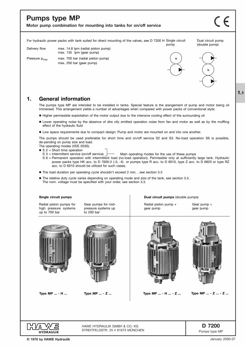
Single circuit pumps Dual circuit pumps (double pumps)
Radial piston pumps forhigh pressure systemsup to 700 bar
Gear pumps for mid-pressure systems upto 200 bar
Radial piston pump +gear pump
Gear pump +gear pump
Type MP ... - H ... Type MP ... - Z ... Type MP ... - H ... - Z ... Type MP ... - Z ... - Z ...
Main operating modes for the use of these pumps
Dual circuit pump(double pump)
Single circuitpump
D 7200 page 2
2. Available versions, main data
2.1. Single circuit pumps (radial piston pumps)
intended for 3-phase mains and for 1-phase mains
Order example: MP 24 A - H 0,81
(cm3/rev) (lpm)(mm) (lpm)
Co
din
g
Pis
ton n
um
ber
1)
Vg
Geo
met
ric
dis
pla
cem
ent
Co
din
g
Del
iver
y flo
w
Qm
ax
Del
iver
y flo
w Q
max
3 + 230/400V 50Hz
Nom. speed 1450 rpm Nom. speed 2850 rpm
Pressure pmax (reference value)
pcold (bar) / pwarm (bar) 3)
Pressure pmax (reference value)
pcold (bar) / pwarm (bar) 3)
MP 14 A MP 24 A MPW 14 MPW 24
H 0,18
H 0,27
H 0,46
H 0,28
H 0,42
H 0,7
H 0,43
H 0,64
H 1,08
H 0,56
H 0,81
H 1,39
H 0,73
H 1,1
H 1,77
H 0,92
H 1,35
H 2,27
4
5
6
7
8
9
2
3
5
2
3
5
2
3
5
2
3
5
2
3
5
2
3
5
0.125
0.19
0.31
0.197
0.29
0.49
0.28
0.42
0.71
0.38
0.58
0.96
0.50
0.75
1.26
0.64
0.95
1.59
0.18
0.27
0.46
0.28
0.42
0.7
0.39
0.64
1.0
0.53
0.82
1.37
0.68
1.07
1.73
0.87
1.32
2.21
700/700
650/550
450/380
330/280
250/210
200/170
450/380
290/245
200/170
150/120
110/90
90/70
700/700
700/700
700/610
700/700
700/650
460/390
700/680
530/450
320/270
570/500
390/330
230/200
430/380
300/250
180/150
340/300
230/200
140/120
700/700
700/700
700/700
700/700
700/700
700/660
700/700
700/700
540/460
570/570
570/560
400/300
430/430
430/430
300/250
340/340
340/340
240/200
530/450
340/290
240/200
170/150
130/110
100/90
700/700
540/460
380/320
280/230
210/180
170/140
700/700
700/700
700/700
700/700
700/700
650/550
700/700
700/640
450/380
570/570
550/470
330/280
430/430
420/360
250/220
340/340
330/280
200/170
700/700
700/670
480/400
700/650
510/430
300/260
530/450
350/300
210/180
390/330
260/220
150/130
300/250
200/170
120/100
230/200
150/130
90/80
0.53
0.88
0.82
1.37
1.18
1.94
1.61
2.69
2.1
3.51
2.71
4.5
MP 12 A MP 22 A MPW 12 MPW 22
Basic type and size
1)
2)
3)
Indications for versions with two pistons:Significant pulsation will occur due to the low number of pistons.Their principal utilization is with gear pumps as dual stage pump (for possible combinations, see section 2.3.1) where a highpressure stage is needed only briefly to achieve a certain pressure level (e.g. at press controls). For complete two stageunits (pump, tank, two stage valve, accessories and valve controls), see D 7200 H.
The motors of the version for 1-phase mains have main and help winding (condenser motors). The condenser is not scope
of delivery and has to be customer furnished.
Attention: The versions for 1-phase (AC) may only start against a very low pressure. Therefore the control must enable a pres-sureless start e.g. by means of an idle circulation solenoid valve, which is held open during start for a period of approx. 0.5to 1s (e.g. by means of a delay relays).
Upper value pcold = Permissible pressure for cold motor and short time operation S 2
Lower value pwarm= Permissible pressure for operation warm motor (max. fluid temperature 80°C) on/off service S 3 and
no-load operation S 6
Version for 3-phase mains
Version for 3-phase mains
Version for 1-phase mains 2)
Version for 1-phase mains 2)
Operation condenser CB (µF) approx. 400V DB
8 16
Operation condenser CB (µF)
12 16
Pump
For gear pumps, see section 2.2.
Specification ofmotor voltage
D 7200 page 3
2)
3)
The motors of the version for 1-phase mains have main and helpwinding (condenser motors). The
condenser is not scope of de-
livery and has to be customer
furnished.
Attention: The versions for 1-phase(AC) may only start against a verylow pressure. Therefore the con-trol must enable a pressurelessstart e.g. by means of an idle circulation solenoid valve, whichis held open during start for a pe-riod of approx. 0.5 to 1s (e.g. bymeans of a delay relays).
Upper value pcold
= Permissible pressure for coldmotor and short time operationS 2
Lower value pwarm
= Permissible pressure for opera-tion warm motor (max. fluid temperature 80°C)on/off service S 3 and no-loadoperation S 6
Single circuit pumps (radial piston pumps), continuation of page 2!
For gear pumps, see section 2.2
(cm3/rev) (lpm)(mm)
Pis
ton d
iam
eter
Pis
ton n
um
ber
1)
Vg
Geo
met
ric
dis
pla
cem
ent
Co
din
g
Del
iver
y flo
w Q
max
Nom. speed 1450 rpm
Pressure pmax (reference value)
pcold (bar) / pwarm (bar) 3)
MP 34 A MP 44 A MP 54 A MPW 34 MPW 44
H 0,3
H 0,6
H 0,9
H 1,4
H 2,1
H 0,41
H 0,83
H 1,25
H 2,08
H 2,9
H 0,5
H 1,0
H 1,5
H 2,6
H 3,7
H 0,8
H 1,6
H 2,5
H 4,2
H 5,8
H 1,2
H 2,4
H 3,6
H 6,0
H 8,4
H 1,45
H 2,8
H 4,3
H 7,0
H 9,8
H 1,7
H 3,3
H 5,1
H 8,3
H 11,8
H 1,9
H 3,8
H 5,6
H 9,5
H 13,3
H 2,2
H 4,4
H 6,5
H 10,9
H 15,3
6
7
8
10
12
13
14
15
16
1
2
3
5
7
1
2
3
5
7
1
2
3
5
7
1
2
3
5
7
1
2
3
5
7
1
2
3
5
7
1
2
3
5
7
1
2
3
5
7
1
2
3
5
7
0.21
0.43
0.64
1.07
1.50
0.29
0.58
0.88
1.46
2.05
0.38
0.76
1.15
1.91
2.67
0.60
1.19
1.79
2.98
4.18
0.86
1.72
2.58
4.30
6.02
1.01
2.02
3.03
5.04
7.06
1.17
2.34
3.51
5.85
8.19
1.34
2.69
4.03
6.72
9.40
1.53
3.06
4.58
7.64
10.70
0.3
0.62
0.92
1.53
2.14
0.41
0.83
1.2
2.0
2.8
0.54
1.1
1.63
2.7
3.8
0.86
1.68
2.54
4.24
5.9
1.2
2.4
3.66
6.1
8.5
1.45
2.8
4.3
7.2
10.0
1.66
3.3
5.0
8.3
11.6
1.9
3.8
5.7
9.5
13.4
2.2
4.3
6.3
10.6
14.8
700/700
700/700
700/700
700/700
700/700
690/590
590/590
590/590
530/450
380/380
380/380
340/290
260/260
260/260
230/200
220/220
220/220
200/170
190/190
190/190
170/150
170/170
170/170
150/130
150/150
150/150
130/110
700/700
700/700
660/570
700/700
700/620
490/410
590/590
560/480
370/320
380/380
360/300
240/200
260/260
250/210
160/140
220/220
210/180
140/120
190/190
180/150
120/100
170/170
160/130
100/90
150/150
140/120
90/80
700/700
700/700
700/600
700/700
700/700
520/440
690/690
660/560
400/340
440/440
420/360
250/210
310/310
290/250
180/150
260/260
250/210
150/130
220/220
220/180
130/110
200/200
190/160
110/95
170/170
170/140
100/85
700/700
700/700
700/700
700/700
700/700
700/700
700/690
700/690
700/690
700/690
550/450
550/450
550/450
540/450
420/350
420/350
420/350
370/320
360/300
360/300
360/300
315/260
300/250
300/250
300/250
275/260
235/200
235/200
235/200
235/200
190/170
190/170
190/170
190/170
700/700
700/700
700/700
700/700
700/700
700/700
700/700
700/700
700/700
580/580
580/580
580/510
410/410
410/410
410/350
350/350
350/350
350/300
300/300
300/300
300/260
260/260
260/260
260/220
230/230
230/230
230/200
Basic type and size
Version for 3-phase mains Vers. for 1-ph. mains 2)
Operation condenser CB (µF)
40 60
Pump
Indications for versions with twopistons:Significant pulsation will occur dueto the low number of pistons.Their principal utilization is with gear pumps as dual stage pump(for possible combinations, seesection 2.3.1) where a high pressure stage is needed onlybriefly to achieve a certain pres-sure level (e.g. at press controls).For complete two stage units(pump, tank, two stage valve, ac-cessories and valve controls), seeD 7200 H.
1)
Del
iver
y flo
w Q
max
D 7200 page 4
2.2. Single circuit pump (gear pump)
Order example: MP 44 A - Z 28
Specification of motorvoltage
3 + 230/400V 50Hz
Basic type and size
Versions for 3-phase and 1-phase mains
(lpm) (lpm)
Vg
Geo
m.
dis
pla
cem
ent
Pum
p c
od
ing
Del
iver
y flo
w Q
max
Nom. speed 1450 rpm
Basic type and size
Nom. speed 2850 rpm
Basic type and size
Pressure pmax (reference value)
pcold (bar) / pwarm (bar) 1) 2)
Pressure pmax (reference value)
pcold (bar) / pwarm (bar) 1) 2)
MP 14 A MP 24 A MP 34 A MP 44 A MP 54 A MP 12 A MP 22 A MP 32 A MP 42 A
Siz
e
(lpm) (lpm)
Vg
Geo
m.
dis
pla
cem
ent
Pum
p c
od
ing
Del
iver
yflo
w Q
max
Del
iver
yflo
w Q
max
Nom. speed 1450 rpm
Basic type and size
Nom. speed 2850 rpm
Basic type and size
Pressure pmax (reference value)
pcold (bar) / pwarm (bar) 1) 2)
Pressure pmax (reference value)
pcold (bar) / pwarm (bar) 1) 2)
MPW 14 MPW 24 MPW 34 MPW 44 MPW 12 MPW 22 MPW 32
size
Z 0,5
Z 1,0
Z 1,8
Z 2,0
Z 2,7
Z 3,5
Z 4,5
Z 5,2
Z 6,9
Z 8,8
Z 9,8
Z 11,3
Z 9,0
Z 12,3
Z 16
Z 21
Z 24
Z 28
Z 37
Z 45
Z 59
Z 75
Z 87
Z 110
Z 135
0.36
0.72
1.3
1.4
1.9
2.41
3.1
3.59
4.76
6.1
7.0
7.9
6.0
8.5
11.0
14.5
17.0
19.5
26
31
41
52
60
76
93
0.5
1.0
1.85
2.0
2.7
3.5
4.5
5.2
6.9
8.8
9.8
11.1
9
12.3
16
21
24
28
37
45
59
75
87
110
135
1.0
2.0
3.7
4
5.4
6.9
9
10.2
13.5
17.5
19.2
21.8
17.1
24.2
31.3
41.3
48.5
55.5
74.1
88
108
150
150/150
150/150
100/85
90/75
70/55
50/45
40/35
35/30
25/20
20/15
15/10
10/10
150/150
150/150
120/100
110/90
80/70
65/55
50/40
40/35
30/25
20/15
20/15
15/10
150/150
150/150
150/150
180/180
160/140
130/110
100/85
85/70
65/55
50/45
40/35
35/30
50/40
35/30
25/20
20/15
20/15
15/10
10/10
150/150
150/150
150/150
180/155
130/110
100/90
80/70
70/60
50/45
40/35
35/30
30/25
40/35
30/25
25/20
15/15
15/10
10/10
10/8
180/180
180/180
180/170
170/160
130/110
110/95
100/90
80/70
70/60
95/70
65/50
50/40
40/30
35/25
30/20
20/15
180/180
180/180
180/180
170/140
140/120
105/90
85/70
70/60
60/50
85/70
60/50
45/40
35/30
30/25
25/20
20/15
180/180
180/180
180/180
170/170
170/170
150/150
150/150
135/135
135/135
200/200
170/150
130/110
100/85
85/75
75/60
55/45
45/40
35/30
25/20
20/20
20/15
15/10
180/180
180/180
180/180
170/170
170/170
150/150
150/150
135/135
135/135
200/200
200/200
200/190
170/145
145/120
125/105
95/80
80/70
60/50
50/40
40/35
30/25
25/20
180/180
180/180
180/180
170/170
170/170
150/150
150/130
135/120
120/105
160/140
110/100
90/75
70/55
60/45
50/40
35/30
24/25
20/20
10/10
0
1
2
3
Z 0,5
Z 1,0
Z 1,8
Z 2,0
Z 2,7
Z 3,5
Z 4,5
Z 5,2
Z 6,9
Z 8,8
Z 9,8
Z 11,3
Z 9,0
Z 12,3
Z 16
Z 21
Z 24
Z 28
Z 37
0.36
0.72
1.3
1.4
1.9
2.41
3.1
3.59
4.76
6.1
7.0
7.9
6.0
8.5
11.0
14.5
17.0
19.5
26
0.5
1.0
1.85
2.0
2.7
3.5
4.5
5.2
6.9
8.8
9.8
11.1
9
12.3
16
21
24
28
37
1.0
2.0
3.7
4
5.4
6.9
9
10.2
13.5
17.5
19.0
21.0
17.1
24.2
31.3
41.3
48.5
55.5
74.1
150/150
110/95
60/50
55/50
40/35
35/30
25/20
20/20
15/15
15/10
10/8
100/85
95/80
50/45
50/45
35/30
30/25
20/20
20/15
15/10
10/10
150/150
150/150
140/120
130/110
95/80
75/65
60/50
50/40
35/30
30/25
25/20
20/15
30/25
20/15
15/10
150/150
150/140
90/75
85/70
60/50
50/40
40/30
30/25
25/20
20/15
15/10
15/10
20/15
15/10
180/180
180/170
155/130
120/100
100/85
80/65
60/50
50/45
45/40
60/50
45/35
35/30
25/20
180/180
150/130
120/100
95/80
80/70
60/50
50/40
40/35
35/30
50/40
35/30
25/20
20/15
180/180
180/180
180/160
170/170
170/150
135/110
110/90
90/80
80/70
110/90
75/65
60/50
45/35
40/30
35/25
25/16
0
1
2
Version for 3-phase mains
Version for 1-phase mains For necessary operation condensers, see tables in sect. 2.1 (page 2 and 3).
(cm3/rev)
(cm3/rev)
1) Upper value pcold
Permissible pressure forcold motor and short timeoperation S 2
Lower value pwarm
Permissible pressure foroperation warm motor(max. fluid temperature80°C) on/off service S 3and no-load operation S 6
2) The middled pressure ofsubsequent load cycles (e.g. at accumulator chargingoperation) should not ex-ceed 50 ... 60% of pcold for
applications above 160 barto ensure an economic service life of the bearings.
Pump coding
Note:
Suction parts are available tothe completion of the pumpacc. to section 6!
D 7200 page 5
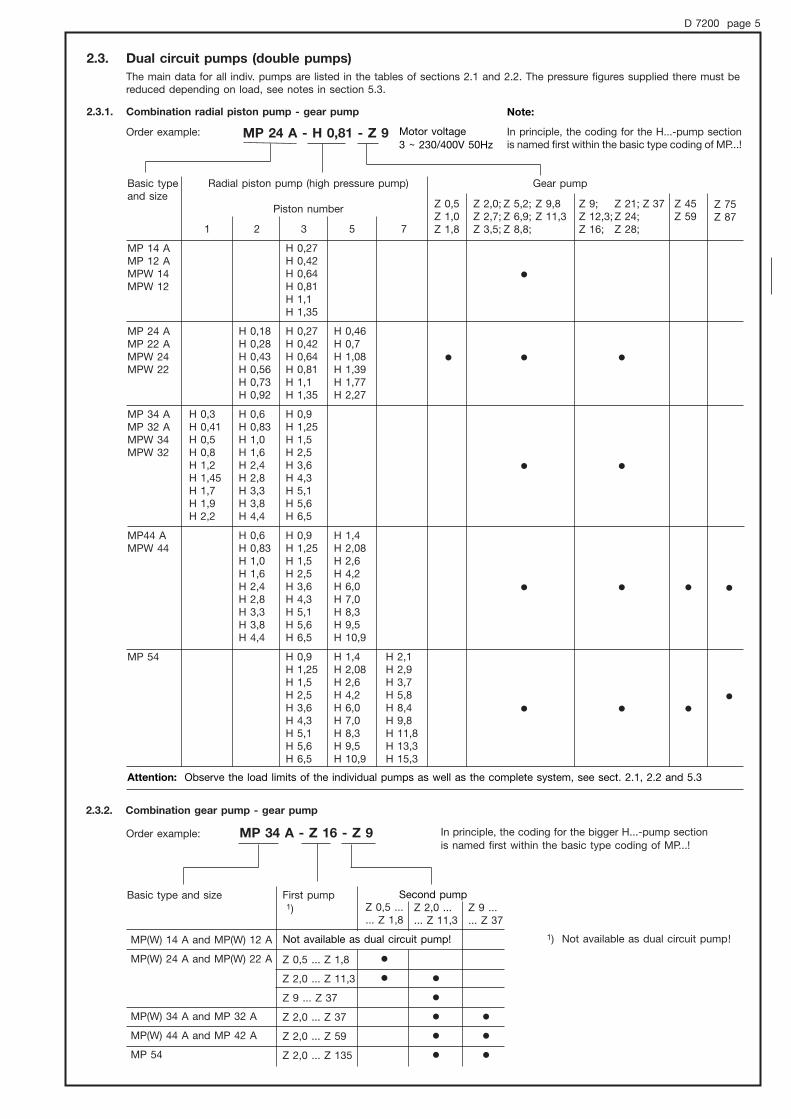
2.3. Dual circuit pumps (double pumps)
The main data for all indiv. pumps are listed in the tables of sections 2.1 and 2.2. The pressure figures supplied there must be reduced depending on load, see notes in section 5.3.
2.3.1. Combination radial piston pump - gear pump
Order example: MP 24 A - H 0,81 - Z 9
Basic typeand size
In principle, the coding for the H...-pump sectionis named first within the basic type coding of MP...!
Gear pump
2.3.2. Combination gear pump - gear pump
Order example: MP 34 A - Z 16 - Z 9
1) Not available as dual circuit pump!
MP 14 AMP 12 AMPW 14 MPW 12
MP 24 AMP 22 AMPW 24 MPW 22
MP 34 AMP 32 AMPW 34MPW 32
MP44 AMPW 44
MP 54
1
H 0,3H 0,41H 0,5H 0,8H 1,2H 1,45H 1,7H 1,9H 2,2
2
H 0,18H 0,28H 0,43H 0,56H 0,73H 0,92
H 0,6H 0,83H 1,0H 1,6H 2,4H 2,8H 3,3H 3,8H 4,4
H 0,6H 0,83H 1,0H 1,6H 2,4H 2,8H 3,3H 3,8H 4,4
3
H 0,27H 0,42H 0,64H 0,81H 1,1H 1,35
H 0,27H 0,42H 0,64H 0,81H 1,1H 1,35
H 0,9H 1,25H 1,5H 2,5H 3,6H 4,3H 5,1H 5,6H 6,5
H 0,9H 1,25H 1,5H 2,5H 3,6H 4,3H 5,1H 5,6H 6,5
H 0,9H 1,25H 1,5H 2,5H 3,6H 4,3H 5,1H 5,6H 6,5
5
H 0,46H 0,7H 1,08H 1,39H 1,77H 2,27
H 1,4H 2,08H 2,6H 4,2H 6,0H 7,0H 8,3H 9,5H 10,9
H 1,4H 2,08H 2,6H 4,2H 6,0H 7,0H 8,3H 9,5H 10,9
7
H 2,1H 2,9H 3,7H 5,8H 8,4H 9,8H 11,8H 13,3H 15,3
Radial piston pump (high pressure pump)
Piston number Z 0,5Z 1,0Z 1,8
'
Z 2,0; Z 5,2; Z 9,8Z 2,7; Z 6,9; Z 11,3Z 3,5; Z 8,8;
'
'
'
'
'
Z 9; Z 21; Z 37Z 12,3; Z 24;Z 16; Z 28;
'
'
'
'
Z 45Z 59
'
'
Z 75Z 87
'
'
In principle, the coding for the bigger H...-pump sectionis named first within the basic type coding of MP...!
Basic type and size
MP(W) 14 A and MP(W) 12 A
MP(W) 24 A and MP(W) 22 A
MP(W) 34 A and MP 32 A
MP(W) 44 A and MP 42 A
MP 54
First pump 1)
Z 0,5 ... Z 1,8
Z 2,0 ... Z 11,3
Z 9 ... Z 37
Z 2,0 ... Z 37
Z 2,0 ... Z 59
Z 2,0 ... Z 135
Z 0,5 ...... Z 1,8
'
'
Z 2,0 ...... Z 11,3
'
'
'
'
'
Z 9 ...... Z 37
'
'
'
Not available as dual circuit pump!
Second pump
Attention: Observe the load limits of the individual pumps as well as the complete system, see sect. 2.1, 2.2 and 5.3
Motor voltage3 + 230/400V 50Hz
Note:
D 7200 page 6
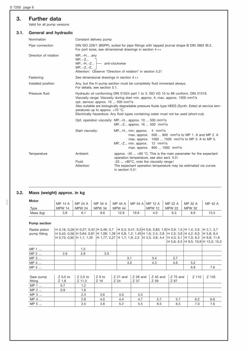
3. Further dataValid for all pump versions
3.1. General and hydraulic
Nomination Constant delivery pump
Pipe connection DIN ISO 228/1 (BSPP), suited for pipe fittings with tapped journal shape B DIN 3862 Bl.2.For port sizes, see dimensional drawings in section 4 ++
Direction of rotation MP...-H... .anyMP...-Z... MP...-H..-Z.. anti-clockwiseMP...-Z..-Z..Attention: Observe “Direction of rotation“ in section 5.2!
Fastening See dimensional drawings in section 4 ++
Installed position Any, but the H pump section must be completely fluid immersed always. For details, see section 5.1.
Pressure fluid Hydraulic oil conforming DIN 51524 part 1 to 3: ISO VG 10 to 68 conform. DIN 51519.Viscosity range: Viscosity during start min. approx. 4; max. approx. 1500 mm2/sopt. service: approx. 10 ... 500 mm2/sAlso suitable are biologically degradable pressure fluids type HEES (Synth. Ester) at service tem-peratures up to approx. +70 °C. Electrically hazardous: Any fluid types containing water must not be used (short-cut).
Opt. operation viscosity: MP...-H... approx. 10 ... 500 mm2/sMP...-Z... approx. 16 ... 500 mm2/s
Start viscosity: MP...-H... min. approx. 4 mm2/smax. approx. 500 ... 800 mm2/s to MP 1. A and MP 2. Amax. approx. 1000 ... 1500 mm2/s to MP 3. A to MP 5.
MP...-Z... min. approx. 12 mm2/smax. approx. 800 ... 1000 mm2/s
Temperature Ambient: approx. -40 ... +60 °C. This is the main parameter for the expectantoperation temperature, see also sect. 5.5 !
Fluid: -25 ... +80°C, note the viscosity range !Attention: The expectant operation temperature may be estimated via curves
in section 5.5 !
3.2. Mass (weight) approx. in kg
Pump section
MP 42 A
13.3
MP 32 A
MPW 32
8.9
MP 22 A
MPW 22
6.3
MP 12 A
MPW 12
4.0
MP 54 A
19.9
MP 44 A
MPW 44
12.8
MP 34 A
MPW 34
8.6
MP 24 A
MPW 24
6.1
MP 14 A
MPW 14
3.8
Type
Mass (kg)
Z 75 andZ 87
5.7
6.5
Z 45 andZ 59
5.7
6.5
Z 28 andZ 37
4.3
4.7
5.5
Z 21 andZ 24
4.0
4.4
5.2
Z 9 toZ 16
3.6
4.0
4.8
Z 2,0 toZ 11,3
1.2
1.6
2.3
2.8
3.5
Z 0,5 toZ 1,8
0.7
0.9
Gear pump fitting
MP 1 ...
MP 2 ...
MP 3 ...
MP 4 ...
MP 5 ...
H 2,1; 3,7H 5,8; 8,4H 9,8; 11,8H 13,3; 15,3
7.6
H 1,4; 2,6H 4,2; 6,0H 7,0; 8,3H 9,5; 10,9
5.2
6.8
H 0,9; 1,5H 2,5; 3,6H 4,3; 5,1H 5,6; 6,5
3.7
4.6
H 0,6; 0,83; 1,0H 1,6; 2,4; 2,8H 3,3; 3,8; 4,4
3.4
4.3
H 0,3; 0,41; 0,5H 0,8; 1,2; 1,45H 1,7; 1,9; 2,2
3.1
4.0
H 0,46; 0,7H 1,08; 1,39H 1,77; 2,27
3.0
H 0,27; 0,42H 0,64; 0,81H 1,1; 1,35
1.5
2.8
H 0,18; 0,28H 0,43; 0,56H 0,73; 0,92
2.6
Radial pistonpump fitting
MP 1 ...
MP 2 ...
MP 3 ...
MP 4 ...
MP 5 ...
Motor
Z 110 Z 135
6.2 6.8
7.0 7.6
D 7200 page 7
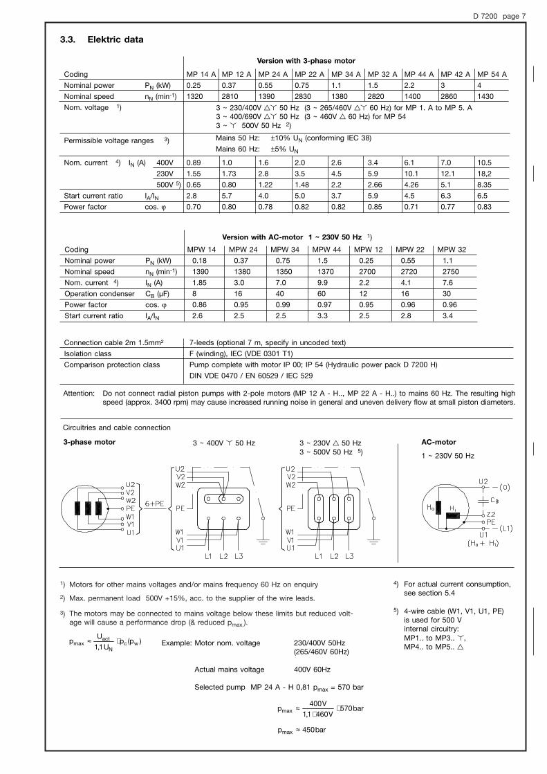
1) Motors for other mains voltages and/or mains frequency 60 Hz on enquiry
2) Max. permanent load 500V +15%, acc. to the supplier of the wire leads.
The motors may be connected to mains voltage below these limits but reduced volt-age will cause a performance drop (& reduced pmax.).
3)
)p(pU1,1
Up wc
N
actmax ⋅≈
MP 54 A
4
1430
10.5
18,2
8.35
6.5
0.83
MP 42 A
3
2860
7.0
12.1
5.1
6.3
0.77
MP 44 A
2.2
1400
6.1
10.1
4.26
4.5
0.71
MP 32 A
1.5
2820
3.4
5.9
2.66
5.9
0.85
MP 34 A
1.1
1380
2.6
4.5
2.2
3.7
0.82
MP 22 A
0.75
2830
2.0
3.5
1.48
5.0
0.82
MP 24 A
0.55
1390
1.6
2.8
1.22
4.0
0.78
MP 12 A
0.37
2810
1.0
1.73
0.80
5.7
0.80
MP 14 A
0.25
1320
0.89
1.55
0.65
2.8
0.70
Coding
Nominal power PN (kW)
Nominal speed nN (min-1)
Nom. voltage 1)
Permissible voltage ranges 3)
400V
230V
500V 5)
Start current ratio IA/INPower factor cos. ϕ
Nom. current 4) IN (A)
3 + 230/400V /! 50 Hz (3 + 265/460V /! 60 Hz) for MP 1. A to MP 5. A3 + 400/690V /! 50 Hz (3 + 460V / 60 Hz) for MP 543 + ! 500V 50 Hz 2)
Version with 3-phase motor
MPW 32
1.1
2750
7.6
30
0.96
3.4
MPW 22
0.55
2720
4.1
16
0.96
2.8
MPW 12
0.25
2700
2.2
12
0.95
2.5
MPW 44
1.5
1370
9.9
60
0.97
3.3
MPW 34
0.75
1350
7.0
40
0.99
2.5
MPW 24
0.37
1380
3.0
16
0.95
2.5
MPW 14
0.18
1390
1.85
8
0.86
2.6
Coding
Nominal power PN (kW)
Nominal speed nN (min-1)
Nom. current 4) IN (A)
Operation condenser CB (µF)
Power factor cos. ϕ
Start current ratio IA/IN
Version with AC-motor 1 + 230V 50 Hz 1)
Mains 50 Hz: ±10% UN (conforming IEC 38)
Mains 60 Hz: ±5% UN
Attention: Do not connect radial piston pumps with 2-pole motors (MP 12 A - H.., MP 22 A - H..) to mains 60 Hz. The resulting highspeed (approx. 3400 rpm) may cause increased running noise in general and uneven delivery flow at small piston diameters.
3.3. Elektric data
Example: Motor nom. voltage 230/400V 50Hz(265/460V 60Hz)
Actual mains voltage 400V 60Hz
Selected pump MP 24 A - H 0,81 pmax = 570 bar
bar570V4601,1
V400pmax ⋅
⋅≈
bar450pmax ≈
4) For actual current consumption, see section 5.4
5) 4-wire cable (W1, V1, U1, PE)is used for 500 V internal circuitry: MP1.. to MP3.. !, MP4.. to MP5.. /
Circuitries and cable connection
3-phase motor AC-motor
1 + 230V 50 Hz
3 + 230V / 50 Hz 3 + 500V 50 Hz 5)
3 + 400V ! 50 Hz
Connection cable 2m 1.5mm²
Isolation class
Comparison protection class
7-leeds (optional 7 m, specify in uncoded text)
F (winding), IEC (VDE 0301 T1)
Pump complete with motor IP 00; IP 54 (Hydraulic power pack D 7200 H)
DIN VDE 0470 / EN 60529 / IEC 529

D 7200 page 8
Type MP(W) 1..-H.. Type MP(W) 1..-Z.. Type MP(W) 1..-H..-Z..
High pressureport
Cable 4x1,5"Length 2000
Low pressureport
Suctionport
4. Unit dimensionsAll dimensions in mm, subject to change without notice!
4.1. Pumps
For missing dimensions, see MP(W) 1..-H..
Type
MP(W) 1..-Z..MP(W) 1..-H..-Z..
Z 0,5Z 1,0Z 1,8Z 2,0toZ 4,5Z 5,2Z 6,9Z 8,8to Z11,3
NP a. S
M 10x1M 10x1M 10x1
G 3/8
G 3/8G 3/8
G 3/8
H1
215215218
221
228228
237
H2
234234236
242
249249
258
B
484848
68
6868
68
a1
101101103
109
112112
121
h2
137137140
143
150150
159
i
7.77.77.7
11
1111
11
Single circuit pump (radial piston pump) Single circuit pump (gear pump) Dual circuit pump
M6,
10 d
eep
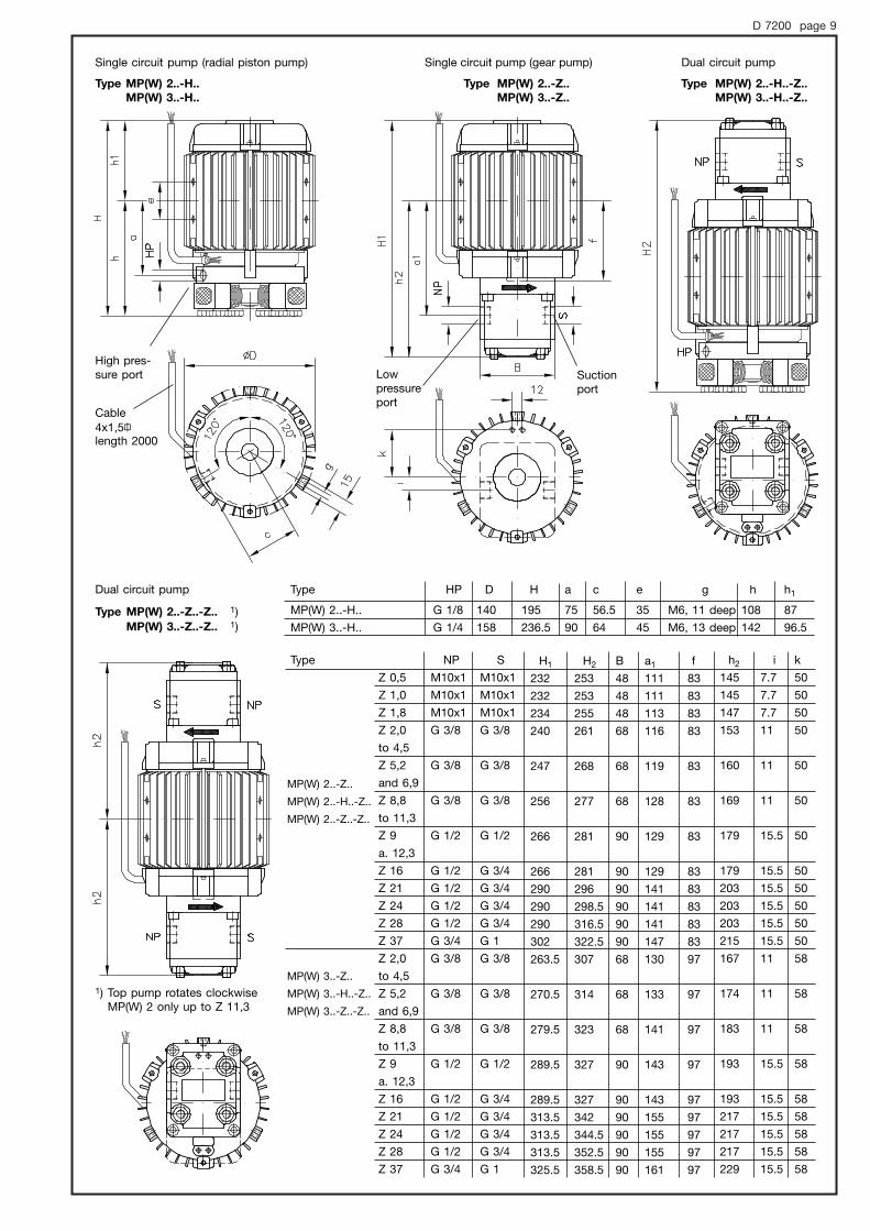
D 7200 page 9
Type MP(W) 2..-H..
MP(W) 3..-H..
Type MP(W) 2..-Z..-Z.. 1)MP(W) 3..-Z..-Z.. 1)
Type MP(W) 2..-Z..
MP(W) 3..-Z..
Type MP(W) 2..-H..-Z..
MP(W) 3..-H..-Z..
1) Top pump rotates clockwiseMP(W) 2 only up to Z 11,3
h1
87
96.5
h
108
142
g
M6, 11 deep
M6, 13 deep
e
35
45
c
56.5
64
a
75
90
H
195
236.5
D
140
158
HP
G 1/8
G 1/4
Type
MP(W) 2..-H..
MP(W) 3..-H..
MP(W) 2..-Z..
MP(W) 2..-H..-Z..
MP(W) 2..-Z..-Z..
MP(W) 3..-Z..
MP(W) 3..-H..-Z..
MP(W) 3..-Z..-Z..
High pres-sure port
Cable4x1,5"length 2000
Lowpressureport
Suctionport
Dual circuit pumpSingle circuit pump (radial piston pump) Single circuit pump (gear pump)
Dual circuit pump
Type
Z 0,5
Z 1,0
Z 1,8
Z 2,0
to 4,5
Z 5,2
and 6,9
Z 8,8
to 11,3
Z 9
a. 12,3
Z 16
Z 21
Z 24
Z 28
Z 37
Z 2,0
to 4,5
Z 5,2
and 6,9
Z 8,8
to 11,3
Z 9
a. 12,3
Z 16
Z 21
Z 24
Z 28
Z 37
NP
M10x1
M10x1
M10x1
G 3/8
G 3/8
G 3/8
G 1/2
G 1/2
G 1/2
G 1/2
G 1/2
G 3/4
G 3/8
G 3/8
G 3/8
G 1/2
G 1/2
G 1/2
G 1/2
G 1/2
G 3/4
S
M10x1
M10x1
M10x1
G 3/8
G 3/8
G 3/8
G 1/2
G 3/4
G 3/4
G 3/4
G 3/4
G 1
G 3/8
G 3/8
G 3/8
G 1/2
G 3/4
G 3/4
G 3/4
G 3/4
G 1
H1
232
232
234
240
247
256
266
266
290
290
290
302
263.5
270.5
279.5
289.5
289.5
313.5
313.5
313.5
325.5
H2
253
253
255
261
268
277
281
281
296
298.5
316.5
322.5
307
314
323
327
327
342
344.5
352.5
358.5
B
48
48
48
68
68
68
90
90
90
90
90
90
68
68
68
90
90
90
90
90
90
a1
111
111
113
116
119
128
129
129
141
141
141
147
130
133
141
143
143
155
155
155
161
f
83
83
83
83
83
83
83
83
83
83
83
83
97
97
97
97
97
97
97
97
97
h2
145
145
147
153
160
169
179
179
203
203
203
215
167
174
183
193
193
217
217
217
229
i
7.7
7.7
7.7
11
11
11
15.5
15.5
15.5
15.5
15.5
15.5
11
11
11
15.5
15.5
15.5
15.5
15.5
15.5
k
50
50
50
50
50
50
50
50
50
50
50
50
58
58
58
58
58
58
58
58
58
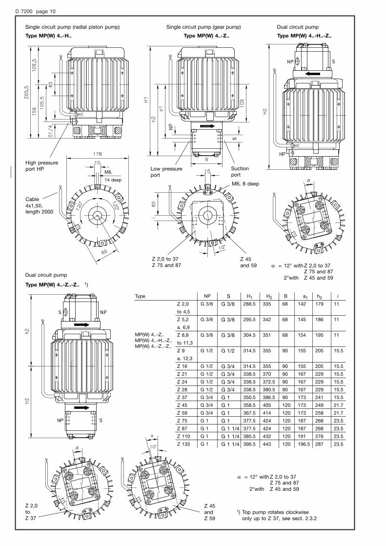
D 7200 page 10
MP(W) 4..-Z..MP(W) 4..-H..-Z..MP(W) 4..-Z..-Z..
Type MP(W) 4..-H..
Type MP(W) 4..-Z..-Z.. 1)
Type MP(W) 4..-Z.. Type MP(W) 4..-H..-Z..
1) Top pump rotates clockwiseonly up to Z 37, see sect. 2.3.2
Cable4x1,5",length 2000
High pressureport HP Low pressure
portSuctionport
Z 2,0 to 37Z 75 and 87
Z 45and 59 α = 12° with Z 2,0 to 37
Z 75 and 872°with Z 45 and 59
α = 12° with Z 2,0 to 37Z 75 and 87
2°with Z 45 and 59
Z 2,0toZ 37
Z 45andZ 59
M6, 8 deep
M8,
Single circuit pump (radial piston pump) Single circuit pump (gear pump) Dual circuit pump
Dual circuit pump
Type
Z 2,0
to 4,5
Z 5,2
a. 6,9
Z 8,8
to 11,3
Z 9
a. 12,3
Z 16
Z 21
Z 24
Z 28
Z 37
Z 45
Z 59
Z 75
Z 87
Z 110
Z 135
NP
G 3/8
G 3/8
G 3/8
G 1/2
G 1/2
G 1/2
G 1/2
G 1/2
G 3/4
G 3/4
G 3/4
G 1
G 1
G 1
G 1
S
G 3/8
G 3/8
G 3/8
G 1/2
G 3/4
G 3/4
G 3/4
G 3/4
G 1
G 1
G 1
G 1
G 1 1/4
G 1 1/4
G 1 1/4
H1
288.5
295.5
304.5
314.5
314.5
338.5
338.5
338.5
350.5
358.5
367.5
377.5
377.5
385.5
396.5
H2
335
342
351
355
355
370
372.5
380.5
386.5
405
414
424
424
432
443
B
68
68
68
90
90
90
90
90
90
120
120
120
120
120
120
a1
142
145
154
155
155
167
167
167
173
173
173
187
187
191
196.5
h2
179
186
195
205
205
229
229
229
241
249
258
268
268
276
287
i
11
11
11
15.5
15.5
15.5
15.5
15.5
15.5
21.7
21.7
23.5
23.5
23.5
23.5
14 deep
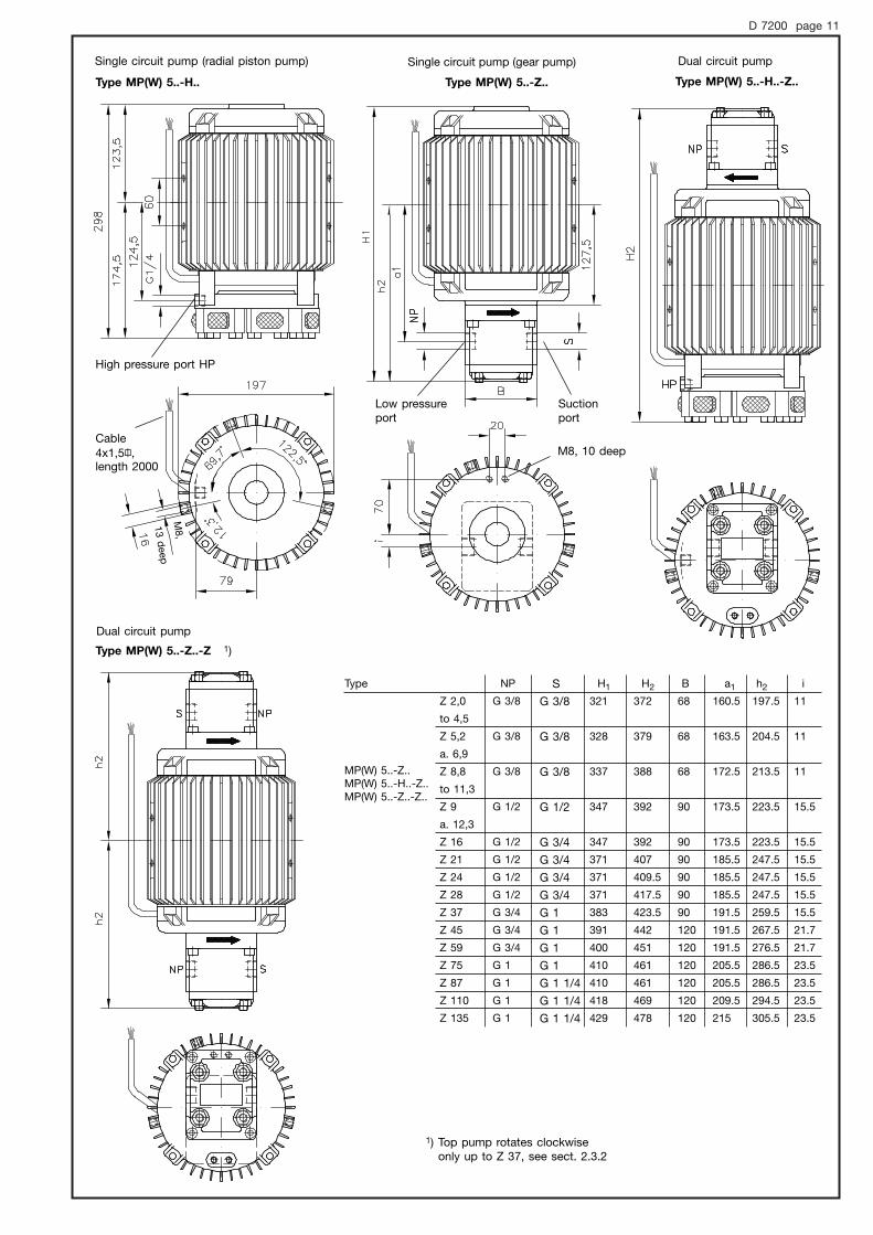
D 7200 page 11
1) Top pump rotates clockwiseonly up to Z 37, see sect. 2.3.2
Type MP(W) 5..-H.. Type MP(W) 5..-Z.. Type MP(W) 5..-H..-Z..
Type MP(W) 5..-Z..-Z 1)
High pressure port HP
Low pressureport
Suctionport
Cable4x1,5",length 2000
M8, 10 deep
Single circuit pump (radial piston pump) Single circuit pump (gear pump) Dual circuit pump
Dual circuit pump
MP(W) 5..-Z..MP(W) 5..-H..-Z..MP(W) 5..-Z..-Z..
Type
Z 2,0
to 4,5
Z 5,2
a. 6,9
Z 8,8
to 11,3
Z 9
a. 12,3
Z 16
Z 21
Z 24
Z 28
Z 37
Z 45
Z 59
Z 75
Z 87
Z 110
Z 135
NP
G 3/8
G 3/8
G 3/8
G 1/2
G 1/2
G 1/2
G 1/2
G 1/2
G 3/4
G 3/4
G 3/4
G 1
G 1
G 1
G 1
S
G 3/8
G 3/8
G 3/8
G 1/2
G 3/4
G 3/4
G 3/4
G 3/4
G 1
G 1
G 1
G 1
G 1 1/4
G 1 1/4
G 1 1/4
H1
321
328
337
347
347
371
371
371
383
391
400
410
410
418
429
H2
372
379
388
392
392
407
409.5
417.5
423.5
442
451
461
461
469
478
B
68
68
68
90
90
90
90
90
90
120
120
120
120
120
120
a1
160.5
163.5
172.5
173.5
173.5
185.5
185.5
185.5
191.5
191.5
191.5
205.5
205.5
209.5
215
h2
197.5
204.5
213.5
223.5
223.5
247.5
247.5
247.5
259.5
267.5
276.5
286.5
286.5
294.5
305.5
i
11
11
11
15.5
15.5
15.5
15.5
15.5
15.5
21.7
21.7
23.5
23.5
23.5
23.5
M8,
13 d
eep
D 7200 page 12
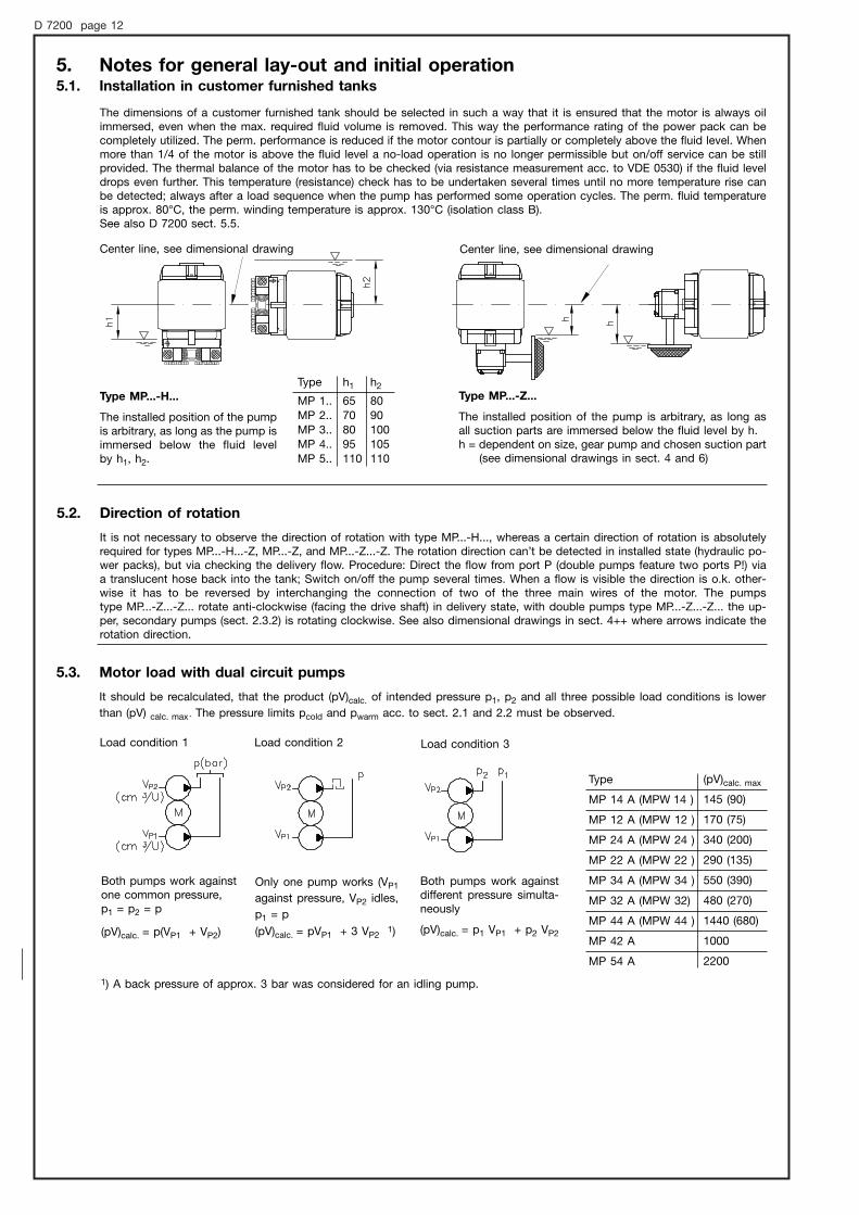
5. Notes for general lay-out and initial operation5.1. Installation in customer furnished tanks
The dimensions of a customer furnished tank should be selected in such a way that it is ensured that the motor is always oil immersed, even when the max. required fluid volume is removed. This way the performance rating of the power pack can becompletely utilized. The perm. performance is reduced if the motor contour is partially or completely above the fluid level. Whenmore than 1/4 of the motor is above the fluid level a no-load operation is no longer permissible but on/off service can be stillprovided. The thermal balance of the motor has to be checked (via resistance measurement acc. to VDE 0530) if the fluid leveldrops even further. This temperature (resistance) check has to be undertaken several times until no more temperature rise canbe detected; always after a load sequence when the pump has performed some operation cycles. The perm. fluid temperatureis approx. 80°C, the perm. winding temperature is approx. 130°C (isolation class B). See also D 7200 sect. 5.5.
Center line, see dimensional drawing Center line, see dimensional drawing
Type MP...-H...
The installed position of the pumpis arbitrary, as long as the pump isimmersed below the fluid level by h1, h2.
h2
8090100105110
h1
65708095110
Type
MP 1..MP 2..MP 3..MP 4..MP 5..
Type MP...-Z...
The installed position of the pump is arbitrary, as long asall suction parts are immersed below the fluid level by h.h = dependent on size, gear pump and chosen suction part
(see dimensional drawings in sect. 4 and 6)
5.2. Direction of rotation
5.3. Motor load with dual circuit pumps
It is not necessary to observe the direction of rotation with type MP...-H..., whereas a certain direction of rotation is absolutely required for types MP...-H...-Z, MP...-Z, and MP...-Z...-Z. The rotation direction can’t be detected in installed state (hydraulic po-wer packs), but via checking the delivery flow. Procedure: Direct the flow from port P (double pumps feature two ports P!) viaa translucent hose back into the tank; Switch on/off the pump several times. When a flow is visible the direction is o.k. other-wise it has to be reversed by interchanging the connection of two of the three main wires of the motor. The pumps type MP...-Z...-Z... rotate anti-clockwise (facing the drive shaft) in delivery state, with double pumps type MP...-Z...-Z... the up-per, secondary pumps (sect. 2.3.2) is rotating clockwise. See also dimensional drawings in sect. 4++ where arrows indicate therotation direction.
Load condition 1 Load condition 2 Load condition 3
Both pumps work againstone common pressure, p1 = p2 = p
(pV)calc. = p(VP1 + VP2)
Only one pump works (VP1
against pressure, VP2 idles,
p1 = p
(pV)calc. = pVP1 + 3 VP21)
Both pumps work againstdifferent pressure simulta-neously
(pV)calc. = p1 VP1 + p2 VP2
1) A back pressure of approx. 3 bar was considered for an idling pump.
It should be recalculated, that the product (pV)calc. of intended pressure p1, p2 and all three possible load conditions is lower
than (pV) calc. max. The pressure limits pcold and pwarm acc. to sect. 2.1 and 2.2 must be observed.
Type
MP 14 A (MPW 14 )
MP 12 A (MPW 12 )
MP 24 A (MPW 24 )
MP 22 A (MPW 22 )
MP 34 A (MPW 34 )
MP 32 A (MPW 32)
MP 44 A (MPW 44 )
MP 42 A
MP 54 A
(pV)calc. max
145 (90)
170 (75)
340 (200)
290 (135)
550 (390)
480 (270)
1440 (680)
1000
2200
D 7200 page 13
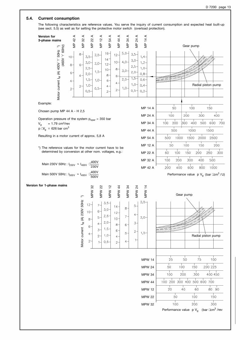
5.4. Current consumption
The following characteristics are reference values. You serve the inquiry of current consumption and expected heat built-up (see sect. 5.5) as well as for setting the protective motor switch (overload protection).
Version for
3-phase mains
Version for 1-phase mains
Mo
tor
curr
ent
I M(A
) 400V
!50H
z 1
)
(460V
!60H
z)
Mo
tor
curr
ent
IM
(A)
230V
50H
z 1
)
Performance value p Vg
MP
42 A
MP
32 A
MP
22 A
MP
12 A
MP
54 A
MP
44 A
MP
34 A
MP
24 A
MP
14 A
MP
W 3
2
MP
W 2
2
MP
W 1
2
MP
W 4
4
MP
W 3
4
MP
W 2
4
MP
W 1
4
MP 14 A
MP 24 A
MP 34 A
MP 44 A
MP 54 A
MP 12 A
MP 22 A
MP 32 A
MP 42 A
MPW 14
MPW 24
MPW 34
MPW 44
MPW 12
MPW 22
MPW 32
/cmbar( 3⋅
Performance value p Vg )U/cmbar( 3⋅
V230
V400II:Hz50V230Main V400V230 ⋅≈
V500
V400II:Hz50V500Main V400V500 ⋅≈
Example:
Chosen pump MP 44 A - H 2,5
Operation pressure of the system poper = 350 bar
Vg = 1.79 cm3/rev
Resulting in a motor current of approx. 5,8 A
1) The reference values for the motor current have to be determined by conversion at other nom. voltages, e.g.:
3g cmbar626Vp =⋅
Gear pump
Gear pump
Radial piston pump
Radial piston pump
/rev
D 7200 page 14
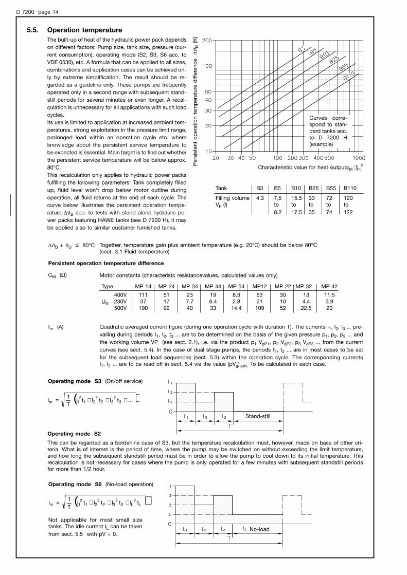
5.5. Operation temperature
The built-up of heat of the hydraulic power pack depends
on different factors: Pump size, tank size, pressure (cur-
rent consumption), operating mode (S2, S3, S6 acc. to
VDE 0530), etc. A formula that can be applied to all sizes,
combinations and application cases can be achieved on-
ly by extreme simplification. The result should be re-
garded as a guideline only. These pumps are frequently
operated only in a second range with subsequent stand-
still periods for several minutes or even longer. A recal-
culation is unnecessary for all applications with such load
cycles.
Its use is limited to application at increased ambient tem-
peratures, strong exploitation in the pressure limit range,
prolonged load within an operation cycle etc. where
knowledge about the persistent service temperature to
be expected is essential. Main target is to find out whether
the persistent service temperature will be below approx.
80°C.
This recalculation only applies to hydraulic power packs
fulfilling the following parameters: Tank completely filled
up, fluid level won’t drop below motor outline during
operation, all fluid returns at the end of each cycle. The
curve below illustrates the persistent operation tempe-
rature |B acc. to tests with stand alone hydraulic po-
wer packs featuring HAWE tanks (see D 7200 H), it may
be applied also to similar customer furnished tanks.
Characteristic value for heat output
Per
sist
ent
op
erat
ion t
emp
erat
ure
diff
eren
ce |
B(K
)
|B + U $ 80°C Together, temperature gain plus ambient temperature (e.g. 20°C) should be below 80°C (sect. 3.1 Fluid temperature)
Persistent operation temperature difference
CM (Ω)
Im (A)
Motor constants (characteristc resistancevalues, calculated values only)
11.53.920
134.422.5
301052
6321109
8.32.814.4
196.433
237.740
511792
11137190
400V230V500V
MP 42MP 32MP 22MP12MP 54MP 44MP 34MP 24MP 14Type
Quadratic averaged current figure (during one operation cycle with duration T). The currents I1, I2, I3 ... pre-
vailing during periods t1, t2, t3 ... are to be determined on the basis of the given pressure p1, p2, p3 ... and
the working volume VP (see sect. 2.1), i.e. via the product p1 VgP1, p2 VgP2, p3 VgP3 ... from the current
curves (see sect. 5.4). In the case of dual stage pumps, the periods t1, t2 ... are in most cases to be set
for the subsequent load sequences (sect. 5.3) within the operation cycle. The corresponding currents I1, I2 ... are to be read off in sect. 5.4 via the value (pVg)calc. To be calculated in each case.
Operating mode S3 (On/off service)
Operating mode S6 (No-load operation)
Operating mode S2
This can be regarded as a borderline case of S3, but the temperature recalculation must, however, made on base of other cri-teria. What is of interest is the period of time, where the pump may be switched on without exceeding the limit temperature,and how long the subsequent standstill period must be in order to allow the pump to cool down to its initial temperature. Thisrecalculation is not necessary for cases where the pump is only operated for a few minutes with subsequent standstill periodsfor more than 1/2 hour.
( )...tItItIT
1I 3
232
221
21m +++=
Not applicable for most small sizetanks. The idle current IL can be taken
from sect. 5.5 with pV = 0.
Curves corre-spond to stan-dard tanks acc.to D 7200 H(example)
UN
Tank B3 B5 B10 B25 B55 B110
Filling volume 4.3 7.5 15.5 33 72 120VF (l) to to to to to
8.2 17.5 35 74 122
( )L2
L32
322
212
1m tItItItIT
1I +++=
No-load
2mM lc ⋅
Stand-still
D 7200 page 15
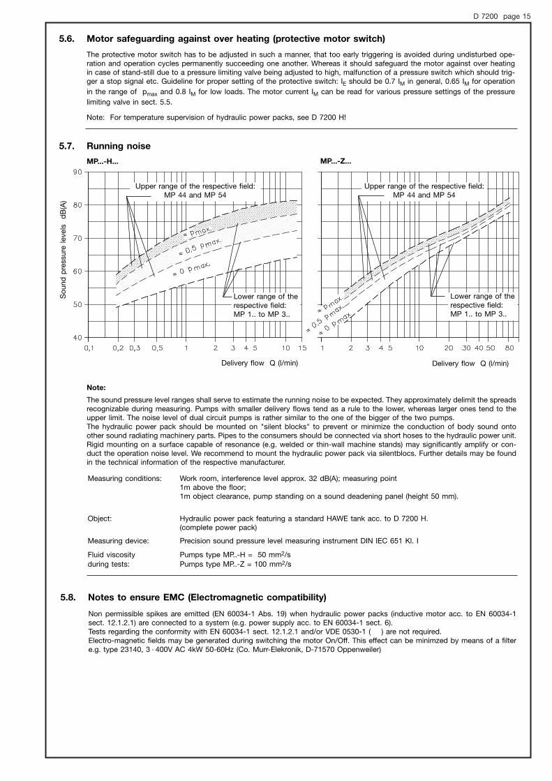
5.7. Running noise
MP...-H... MP...-Z...
Note:
The sound pressure level ranges shall serve to estimate the running noise to be expected. They approximately delimit the spreadsrecognizable during measuring. Pumps with smaller delivery flows tend as a rule to the lower, whereas larger ones tend to the upper limit. The noise level of dual circuit pumps is rather similar to the one of the bigger of the two pumps.The hydraulic power pack should be mounted on "silent blocks" to prevent or minimize the conduction of body sound onto other sound radiating machinery parts. Pipes to the consumers should be connected via short hoses to the hydraulic power unit.Rigid mounting on a surface capable of resonance (e.g. welded or thin-wall machine stands) may significantly amplify or con-duct the operation noise level. We recommend to mount the hydraulic power pack via silentblocs. Further details may be foundin the technical information of the respective manufacturer.
Measuring conditions: Work room, interference level approx. 32 dB(A); measuring point1m above the floor; 1m object clearance, pump standing on a sound deadening panel (height 50 mm).
Object: Hydraulic power pack featuring a standard HAWE tank acc. to D 7200 H.(complete power pack)
Measuring device: Precision sound pressure level measuring instrument DIN IEC 651 Kl. I
Fluid viscosity Pumps type MP..-H = 50 mm2/sduring tests: Pumps type MP..-Z = 100 mm2/s
5.6. Motor safeguarding against over heating (protective motor switch)
Note: For temperature supervision of hydraulic power packs, see D 7200 H!
The protective motor switch has to be adjusted in such a manner, that too early triggering is avoided during undisturbed ope-ration and operation cycles permanently succeeding one another. Whereas it should safeguard the motor against over heatingin case of stand-still due to a pressure limiting valve being adjusted to high, malfunction of a pressure switch which should trig-ger a stop signal etc. Guideline for proper setting of the protective switch: IE should be 0.7 IM in general, 0.65 IM for operation
in the range of pmax and 0.8 IM for low loads. The motor current IM can be read for various pressure settings of the pressure
limiting valve in sect. 5.5.
So
und
pre
ssure
lev
els
dB
(A)
Delivery flow Q (l/min) Delivery flow Q (l/min)
Upper range of the respective field:MP 44 and MP 54
Upper range of the respective field:MP 44 and MP 54
Lower range of therespective field: MP 1.. to MP 3..
Lower range of therespective field: MP 1.. to MP 3..
5.8. Notes to ensure EMC (Electromagnetic compatibility)
Non permissible spikes are emitted (EN 60034-1 Abs. 19) when hydraulic power packs (inductive motor acc. to EN 60034-1sect. 12.1.2.1) are connected to a system (e.g. power supply acc. to EN 60034-1 sect. 6).Tests regarding the conformity with EN 60034-1 sect. 12.1.2.1 and/or VDE 0530-1 ( ) are not required.Electro-magnetic fields may be generated during switching the motor On/Off. This effect can be minimzed by means of a filtere.g. type 23140, 3 400V AC 4kW 50-60Hz (Co. Murr-Elekronik, D-71570 Oppenweiler)·
D 7200 page 16
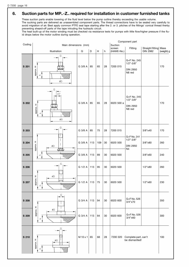
6. Suction parts for MP..-Z.. required for installation in customer furnished tanks
These suction parts enable lowering of the fluid level below the pump outline thereby exceeding the usable volume.The sucking parts are delivered as unassembled component parts. The thread connections have to be sealed very carefully to avoid migration of air. Best apply common PTFE seal tape starting after the 2. or 3. pitches of the fittings‘ conical thread therbypreventing sheard-off parts of the tape intruding the hydraulic circuit. The heat built-up of the motor winding must be checked via resistance tests for pumps with little flow/higher pressure if the flu-id drops below the motor outline during operation.
Coding
S 201
S 202
S 203
S 204
S 205
S 206
S 207
S 208
S 209
S 210
Main dimensions (mm)
Illustration
G+F No. 2451/2”-3/8”
DIN 2950N8 red
G+F No. 2451/2”-3/8”
DIN 2950N8 red
G+F No. 2411/2”-3/8”
DIN 2950N4
G+F No. 5263/4”x70
G+F No. 5263/4”x60
Component part
Suctionscreen(HAWE-No.)G
G 3/8 A
G 3/8 A
G 3/8 A
G 3/8 A
G 3/8 A
G 1/2 A
G 1/2 A
G 3/4 A
G 3/4 A
M 10 x 1
Mass(weight) g
170
170
170
260
240
260
230
350
300
100
7200 015
6020 500 a
7200 015
6020 500
6020 500
6020 500
6020 500
6020 600
6020 600
Straight fittingDIN 2982
3/8”x40
3/8”x80
3/8”x60
1/2”x80
1/2”x60
D
85
85
85
113
113
113
113
113
113
65
H
65
65
75
109
89
95
75
94
84
68
h
28
28
28
30
30
30
30
30
30
28
Fitting
7200 020 Complete part, can’tbe dismantled!
app
rox.
Hap
pro
x. H
app
rox.
Hap
pro
x. H
app
rox.
Hap
pro
x. H