(psns/cdmnps) composite thin film for its a
TRANSCRIPT

ii
SYNTHESIS OF SELF–ASSEMBLED POLYSTYRENE
NANOSPHERES/CADMIUM METAL NANOPARTICLES (PSNs/CdMNPs)
COMPOSITE THIN FILM FOR ITS APPLICATION AS
ADSORBENT AND CATALYST
PRATAMA JUJUR WIBOWA
A thesis submitted in fulfillment of the requirement for the award of the
Doctor of Philosophy
Faculty of Science, Technology and Human Development
Universiti Tun Hussein Onn Malaysia
MAY, 2015

ix
ABSTRACT
The research described in this dissertation is a comprehensive account of an attempt,
for the first time, correlates the secondary pores structural and physicochemical properties of
polystyrene nanospheres/cadmium metal nanoparticles (PSNs/CdMNPs) composite thin film
with its adsorption and catalytic properties. The PSNs/CdMNPs composites were fabricated
on a hydrophilic silicon wafer through self-assembly process from its aqueous colloidal. The
existence of secondary pores and atomic particles of cadmium were clarified by using a field
emission scanning electron microscopy (FESEM) and an energy dispersive X–ray (EDX)
spectroscopy, respectively. Physical and chemical physical stability of the secondary pores
were tested toward continuous laser irradiation of 633 nm wavelength and oxygen/argon
reactive ion etching (O2/Ar RIE), respectively. Thermal catalytic effect of CdMNPs was
investigated through thermogravimetry/differential thermal analysis (TG/DTA). Any
chemical bond change of the PSNs/CdMNPs composite due to both CdMNPs and adsorbate
molecules were confirmed by using an attenuated total reflectance–Fourier transform infrared
(ATR–FTIR) spectroscopy. The capability of adsorption and catalysis of the secondary pores
were clarified to adsorb and degrade tartazine as a model compound. It was found that the
fabricated secondary pores were composed of dumbbell-like nanostructure with >100 nm
pores in size had better adsorption capability than other adsorbents. It was demonstrated that
the Freundlich constants ratio expressed as KF/n was 1.715 104. This value is much higher
than previously reported for coconut shell activated carbon (CSAC), i.e. 0.158 and
commercial activated carbon (CAC), i.e. 0.403. The rate of catalytic degradation of tartrazine
on secondary pores was 0.718 µmol min–1
and a good agreement with pseudo first–order
kinetics. Nanostructures of the secondary pores of PSNs/CdMNPs were not significantly
changed under 633 nm continuous laser irradiation for 20 minutes as well as under O2/Argon
RIE (30 sccm argon flow rate, 15 sccm oxygen flow rate, 20 seconds) suggesting a strong
structural integrity of the secondary pores. Based on these results, it was concluded that
PSNs/CdMNPs composites thin film secondary pores showed the adsorption and catalytic
capabilities and is considered a potential adsorbent and catalyst.
x
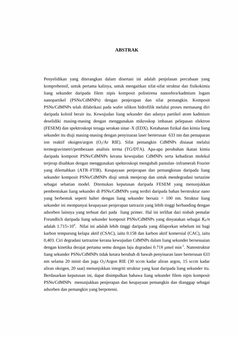
ABSTRAK
Penyelidikan yang diterangkan dalam disertasi ini adalah penjelasan percubaan yang
komprehensif, untuk pertama kalinya, untuk mengaitkan sifat-sifat struktur dan fisikokimia
liang sekunder daripada filem nipis komposit polistirena nanosfera/kadmium logam
nanopartikel (PSNs/CdMNPs) dengan penjerapan dan sifat pemangkin. Komposit
PSNs/CdMNPs telah difabrikasi pada wafer silikon hidrofilik melalui proses memasang diri
daripada koloid berair itu. Kewujudan liang sekunder dan adanya partikel atom kadmium
deselidiki masing-masing dengan menggunakan mikroskop imbasan pelepasan elektron
(FESEM) dan spektroskopi tenaga serakan sinar–X (EDX). Ketahanan fizikal dan kimia liang
sekunder itu diuji masing-masing dengan penyinaran laser berterusan 633 nm dan pemaparan
ion reaktif oksigen/argon (O2/Ar RIE). Sifat pemangkin CdMNPs disiasat melalui
termogravimetri/pembezaan analisis terma (TG/DTA). Apa-apa perubahan ikatan kimia
daripada komposit PSNs/CdMNPs kerana kewujudan CdMNPs serta kehadiran molekul
terjerap disahkan dengan menggunakan spektroskopi mengubah pantulan–inframerah Fourier
yang dilemahkan (ATR–FTIR). Keupayaan penjerapan dan pemangkinan daripada liang
sekunder komposit PSNs/CdMNPs diuji untuk menjerap dan untuk mendegradasi tartazine
sebagai sebatian model. Ditemukan keputusan daripada FESEM yang menunjukkan
pembentukan liang sekunder di PSNs/CdMNPs yang terdiri daripada bahan berstruktur nano
yang berbentuk seperti halter dengan liang sekunder bersaiz > 100 nm. Struktur liang
sekunder ini mempunyai keupayaan penjerapan tartrazin yang lebih tinggi berbanding dengan
adsorben lainnya yang terbuat dari pada liang primer. Hal ini terlihat dari nisbah pemalar
Freundlich daripada liang sekunder komposit PSNs/CdMNPs yang dinyatakan sebagai KF/n
adalah 1.715 104. Nilai ini adalah lebih tinggi daripada yang dilaporkan sebelum ini bagi
karbon tempurung kelapa aktif (CSAC), iaitu 0.158 dan karbon aktif komersial (CAC), iaitu
0,403. Ciri degradasi tartrazine kerana kewujudan CdMNPs dalam liang sekunder bersesuaian
dengan kinetika derajat pertama semu dengan laju degradasi 0.718 μmol min-1
. Nanostruktur
liang sekunder PSNs/CdMNPs tidak ketara berubah di bawah penyinaran laser berterusan 633
nm selama 20 minit dan juga O2/Argon RIE (30 sccm kadar aliran argon, 15 sccm kadar
aliran oksigen, 20 saat) menunjukkan integriti struktur yang kuat daripada liang sekunder itu.
Berdasarkan keputusan ini, dapat disimpulkan bahawa liang sekunder filem nipis komposit
PSNs/CdMNPs menunjukkan penjerapan dan keupayaan pemangkin dan dianggap sebagai
adsorben dan pemangkin yang berpotensi.

xi
CONTENTS
TITLE i
DECLARATION iii
DEDICATION vi
AKCNOWLEDGEMENT vii
ABSTRACT ix
CONTENTS xi
LIST OF TABLES xvi
LIST OF FIGURES xvii
LIST OF SYMBOLS xxiii
LIST OF ABBREVIATIONS xxvii
LIST OF APPENDICES xxxi
CHAPTER 1 INTRODUCTION 1
1.1 Background 1
1.2 Problem Statement 4
1.3 Hypothesis 5
1.3 The Aim 6
1.4 Objectives 6
1.5 Scope 6
CHAPTER 2 LITERATURE REVIEW 8
2.1 Introduction 8
2.2 Pores classification 8
2.3 Primary pores and secondary pores of PSNs/CdMNPs composite thin film 11

xii
2.3.1 Primary pores of PSNs/CdMNPs composite thin film 12
2.3.2 Secondary Pores of PSNs/CdMNPs composite thin film 14
2.4 Synthesis and fabrication of PSNs/CdMNPs scondary pores-based orous
anocomposite thin film materials
17
2.4.1 Synthesis 17
2.4.2 Fabrication 21
2.5 Characterization 23
2.5.1 Thermal properties 23
2.5.2 Surface morphology and CdMNPs mapping 25
2.5.3 Chemical bonding vibrations 26
2.5.4 Stability on laser irradiation 28
2.5.5 Stability on oxygen/argon reactive ion etching 28
2.5.6 Capability of adsorption 29
2.5.7 Capability of catalysis 31
CHAPTER 3 RESEARCH METHODOLOGY 33
3.1 Introduction 33
3.2 Preparation of reagents and materials 35
3.2.1 Cadmium metal nanoparticles precursor solution stock 35
3.2.2 PSNs of 200 nm in average size aqueous colloidal stock 36
3.2.3 Sodium borohydride solution 37
3.2.4 Piranha solution 37
3.2.5 Hydrophilic silicon wafer 38
3.2.6 Tartrazine solution stock 38
3.3 Experimental design 39
3.3.1 Synthesis of aqueous colloidal of PSNs/CdMNPs composite 39
3.3.1.1 Chemical reduction 40
3.3.1.2 Physical reduction 40
3.3.2 Fabrication of secondary pores of PSNs/CdMNPs composite
thin film
41
3.3.2.1 Under chemical reduction 41
3.3.2.2 Under physical reduction 42

xiii
3.3.3 Characterization of secondary pores of PSNs/CdMNPs
composite thin film material
43
3.3.3.1 Thermal characters 43
3.3.3.2 Surface morphology 44
i. PSNs/CdMNPs composite thin film fabricated from
its aqueous colloidal under chemical reduction.
44
ii. PSNs/CdMNPs composite thin film fabricated from
its aqueous colloidal under physical reduction.
44
3.3.3.3 Stability of secondary pores 44
i. Under contineous laser irradiation. 45
ii. Under O2/Ar plasma reactive ion etching (RIE)
exposure.
45
3.3.3.4 Cadmium metal existence analysis 46
3.3.3.5 Chemical bonds vibrations analysis 46
3.3.4 Application of secondary pores of PSNs/CdMNPs composite
thin film as adsorbent and decolourization/mass degradation
catalyst
46
3.3.4.1 Adsorption and catalytic decolourization/mass
degradation
47
3.3.4.2 Application of PSNs/MNPsCd composite an adsorbent 48
3.3.4.3 Application of PSNs/MNPsCd composite as a catalyst 48
CHAPTER 4 RESULTS AND DISCUSSION
49
4.1 Introduction 49
4.2 Experimental design 50
4.2.1 Synthesis of aqueous colloidal of PSNs/CdMNPs composite 50
4.2.1.1 Chemical reduction 50
4.2.1.2 Physical reduction 55
4.2.2 Fabrication of secondary pores of PSNs/CdMNPs composite thin
film
57
4.2.2.1 Under chemical reduction 58
4.2.2.2 Under physical reduction 60

xiv
4.2.3 Characterization of secondary pores of PSNs/CdMNPs
composite thin film material
61
4.2.3.1 Thermal properties of aqueous colloidal
PSNs/CdMNPs composite
62
i. Homogenity of PSNs/CdMNPs 64
ii. Catalytic character of CdMNPs 68
4.2.3.2 Surface morphology 69
i. PSNs/CdMNPs composite thin film fabricated from
its aqueous colloidal under chemical reduction.
70
ii. PSNs/CdMNPs composite thin film fabricated from
its aqueous colloidal under physical reduction.
74
4.2.3.3 Stability of secondary pores 76
i. Under contineous laser irradiation. 77
ii. Under O2/Ar plasma reactive ion etching (RIE)
exposure.
79
4.2.3.4 Cadmium metal existence 84
4.2.3.5 Chemical bonds vibrations 87
4.2.4 Application of secondary pores of PSNs/CdMNPs composite
thin film as adsorbent and decolourization/mass degradation
catalyst
90
4.2.4.1 Survey the specific ATR–FTR spectra 90
4.2.4.2 Quantitative analysis of adsorbed tartrazine for the
various times
93
i. The maximum adsorption capacity on the
Langmuir isotherm adsorption
102
ii. The maximum adsorption capacity on the
Freundlich isotherm adsorption and its application
as an adsorbent
103
4.2.4.3 Catalytic degradation/decolourization and its
application as a catalyst material
108

xv
CHAPTER 5 CONCLUSIONS AND RECOMMENDATIONS
118
5.1 Conclusions 118
5.2 Recommendations 120
i. Synthesis of aqueous colloidal PSNs/CdMNPs composite 120
ii. Fabrication of PSNs/CdMNPs composite thin film material
secondary pore
121
iii. Investigation of the adsorption and catalytic capability 121
iv. The models of secondary pores for tartrazine adsorption 121
v. Application of the secondary pores models 124
vi. Effect of CdMNPs in tartrazine adsorption 127
vii. Potential energy of adsorption 128
REFERENCES 133
APPENDICES 152
VITAE
LIST OF PAPERS PUBLISHED IN JOURNALS
LIST OF PAPERS PRESENTED IN CONFERENCES
PAPERS PUBLISHED IN SCOPUS-INDEXED JOURNALS/
CONFERENCE PROCEEDING
xvi
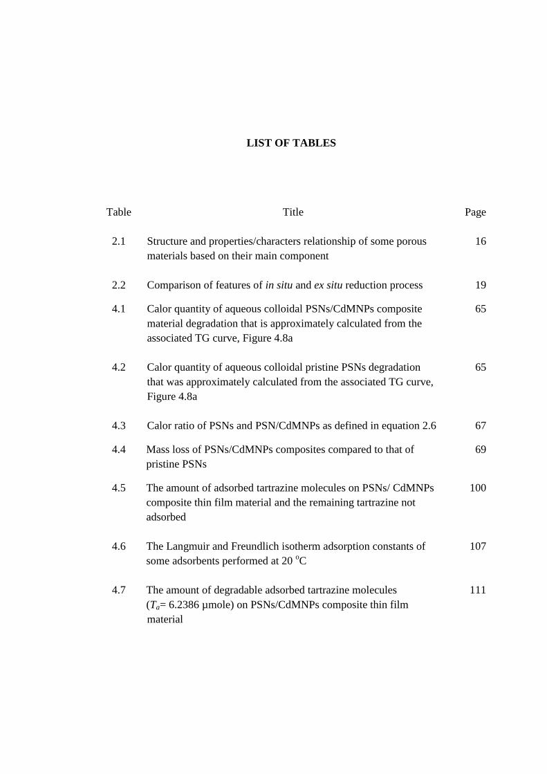
LIST OF TABLES
Table
Title Page
2.1 Structure and properties/characters relationship of some porous
materials based on their main component
16
2.2 Comparison of features of in situ and ex situ reduction process 19
4.1 Calor quantity of aqueous colloidal PSNs/CdMNPs composite
material degradation that is approximately calculated from the
associated TG curve, Figure 4.8a
65
4.2 Calor quantity of aqueous colloidal pristine PSNs degradation
that was approximately calculated from the associated TG curve,
Figure 4.8a
65
4.3 Calor ratio of PSNs and PSN/CdMNPs as defined in equation 2.6 67
4.4 Mass loss of PSNs/CdMNPs composites compared to that of
pristine PSNs
69
4.5 The amount of adsorbed tartrazine molecules on PSNs/ CdMNPs
composite thin film material and the remaining tartrazine not
adsorbed
100
4.6 The Langmuir and Freundlich isotherm adsorption constants of
some adsorbents performed at 20 oC
107
4.7 The amount of degradable adsorbed tartrazine molecules
(Ta= 6.2386 µmole) on PSNs/CdMNPs composite thin film
material
111

xvii
LIST OF FIGURES
Figure
Title Page
2.1 Schematic illustration of primary pores classification based on
the interconnection to the particle surface, and shape. (a)
closed pores; (b, c, d, e) opened pores; (c, e, f) cylindrical
shaped pores; (b) ink-bottle shaped pores; (d) funnel shaped
pores
9
2.2 Schematic illustration of primary pores models revealed in
PSNs particle body of 200 nm size. (a) India traditional
trumpet-like pore; (b) face-to-face junction bottle neck–like
pore; (c) randomly irregular form pore, and (d) straightforward
pipe-like pore
10
2.3 Schematic illustration of secondary pores models revealed
among four PSNs particle bodies of 200 nm size
10
2.4 Three conformational structures of polystyrene skeleton chain 12
2.5 Molecular chain conformation of crystalline phases of
syndiotactic polystyrene
13
2.6 Schematic illustration of the individual primary pores models
revealed in PSNs particle body of 200 nm size proposed by
Wibawa et al. (2011)[58]
14
2.7 FESEM images of (a) secondary pores revealed inter PSNs
particles body, multilayer PSNs thin film deposit [37]; (b)
ordered single layer PSNs thin film deposit [38]; and (c)
disordered single layer PSNs thin film deposit [39].
15
2.8 Schematic illustration of (a) ex situ reduction process of metal
precursor M+ to metal nanoparticles (MNPs) and (b) that of in
situ one
18

xviii
2.9 Schematic illustration of the structure of dispersion
system in water medium
20
2.10 Schematic illustration of (a) solvated state of positive ion and
negative ion, and (b) in water
20
2.11 Schematic illustration of the self-assembly process driven by
capillary force. (a) Lateral capillary forces appear when there
is disorderly motion of colloidal particles in a liquid thick layer
on a substrate, and (b) ordered state gives rise to aggregation
after the top of particles protrude from the liquid layer
21
3.1 Flowchart of the experimental work 34
3.2 Schematic illustration of the fabrication of secondary pores-
based porous PSNs/CdMNPs composite thin film material.
42
3.3 Photograph of the investigation of (a) adsorption capability of
the fabricated PSNs/CdMNPs composite thin film material,
adsorption and catalytic decolorization process, and (b) the
process is over
47
4.1 Schematic illustration of (a) in situ chemical reduction
experiment of Cd metal precursor to Cd metal nanoparticles in
aqueous colloidal PSNs to form PSNs/CdMNPs composite
without stabilizer, before reduction, and (b) after reduction
51
4.2 pH paper showed aqueous colloidal PSNs/CdMNPs composite
of about pH 5
54
4.3 Schematic illustration of the distribution of additional
constituents of aqueous colloidal PSNs/CdMNPs composite
54
4.4 Schematic illustration of a “hot spot” mechanism model
occurring on the formation of Cd metal nanoparticles in an
aqueous colloidal PSNs/Cd(NO3)2.4H2O composite
56
4.5 The photograph of solid-phase thin film of PSNs/CdMNPs
produced in the experiment performed in section 3.3.2.1
58
xix
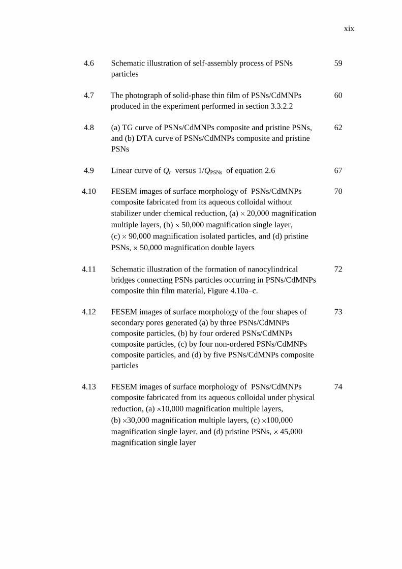
4.6 Schematic illustration of self-assembly process of PSNs
particles
59
4.7 The photograph of solid-phase thin film of PSNs/CdMNPs
produced in the experiment performed in section 3.3.2.2
60
4.8 (a) TG curve of PSNs/CdMNPs composite and pristine PSNs,
and (b) DTA curve of PSNs/CdMNPs composite and pristine
PSNs
62
4.9 Linear curve of Qr versus 1/QPSNs of equation 2.6 67
4.10 FESEM images of surface morphology of PSNs/CdMNPs
composite fabricated from its aqueous colloidal without
stabilizer under chemical reduction, (a) 20,000 magnification
multiple layers, (b) 50,000 magnification single layer,
(c) 90,000 magnification isolated particles, and (d) pristine
PSNs, 50,000 magnification double layers
70
4.11 Schematic illustration of the formation of nanocylindrical
bridges connecting PSNs particles occurring in PSNs/CdMNPs
composite thin film material, Figure 4.10a–c.
72
4.12 FESEM images of surface morphology of the four shapes of
secondary pores generated (a) by three PSNs/CdMNPs
composite particles, (b) by four ordered PSNs/CdMNPs
composite particles, (c) by four non-ordered PSNs/CdMNPs
composite particles, and (d) by five PSNs/CdMNPs composite
particles
73
4.13 FESEM images of surface morphology of PSNs/CdMNPs
composite fabricated from its aqueous colloidal under physical
reduction, (a) 10,000 magnification multiple layers,
(b) 30,000 magnification multiple layers, (c) 100,000
magnification single layer, and (d) pristine PSNs, 45,000
magnification single layer
74

xx
4.14 FESEM images of surface morphology of the four shapes of
secondary pores generated (a) by three PSNs/CdMNPs
composite particles, (b) by four ordered PSNs/CdMNPs
composite particles, (c) by four non-ordered PSNs/CdMNPs
composite particles, and (d) by five PSNs/CdMNPs composite
particles
75
4.15 FESEM images of surface morphology of the isolated
PSNs/CdMNPs composite particles
76
4.16 FESEM images of surface morphology of the laser-irradiated
PSNs/CdMNPs composites thin film material (a) 10,000
magnification, and (b) 100,000 magnification
77
4.17 FESEM images of surface morphology of (a) O2/Ar RIE-
etched PSNs/CdMNPs composite, 50,000 magnification, and
(b) O2/Ar RIE-etched pristine PSNs, 50,000 magnification
80
4.18 Schematic illustration of the proposed mechanism of the
change in size and shape of the secondary pores in a disorderly
array of dumbbell-like nanostructure framework of
PSNs/CdMNPs composite
81
4.19 EDX spectrum of PSNs/CdMNPs composite thin film of
Figure 4.13a–c
85
4.20 EDX spectrum of pristine PSNs
86
4.21 The mapping of EDX spectrum of Cd metal nanoparticles
distribution in the fabricated PSNs/CdMNPs composite thin
film of Figure 4.13a–c
86
4.22 ATR–FTIR spectra of (a) pristine PSNs, (b) PSNs/CdMNPs
composite thin film, and (c) three-dimensional molecular
structure of atactic conformational polystyrene illustrated by
Wibawa et al (2010) [157]
88
4.23 ATR-FTIR spectra of (a) pristine PSNs, (b) PSNs/CdMNPs
composite material, and (c) tartrazine molecule. These spectra
were analyzed according to the sequence steps of tune–up,
ATR correction, base line correction and normalization mode
91

xxi
4.24 Molecular structure of (a) tartrazine without intra molecular
hydrogen bonding, (b) with intra molecular hydrogen bonding,
and (c) with both intra molecular hydrogen bonds and Csp2–H
stretching vibration disturbed by oxygen and nitrogen atom
neighbor
92
4.25 ATR-FTIR spectra of (a) pristine PSNs-tartrazine 25‟, (b)
PSNs/CdMNPs-tartrazine 5‟, (c) PSNs/CdMNPs-tartrazine
10‟, (d) PSNs/CdMNPs-tartrazine 15‟, (e) PSNs/CdMNPs-
tartrazine 20‟, and (f) PSNs/CdMNPs-tartrazine 25‟
95
4.26 A curve of degradable adsorbed tartrazine molecules on the
surface of PSNs/CdMNPs composite material
96
4.27 A curve of adsorbed tartrazine molecules on the surface of
PSNs/CdMNPs composite material
97
4.28 A linear curve correlated the percentage amount of adsorbed
tartrazine molecules, %w/v Ta, versus adsorbed tartrazine
equivalence, A2/A1 in arbitrary unit (a. u)
99
4.29 A curve of the rate of tartrazine adsorption on PSNs/CdMNPs
composite thin film surface
101
4.30 A curve of Langmuir isotherm adsorption correlated Tr/Ta
versus Tr of tartrazine adsorption on PSNs/CdMNPs composite
thin film surface for the Langmuir constants determination
103
4.31 A curve of Freundlich isotherm adsorption correlated log Ta /Tr
versus log Tr of adsorbed tartrazine molecules on
PSNs/CdMNPs composite thin film surface
105
4.32 A linear curve correlating %A2/A1 versus A2/A1 of degradable
adsorbed tartrazine for the determination of η value
110
4.33 Tartrazine degradation curve correlating the amount of
degradable tartrazine (Tgd) versus time of degradation (t)
occurring on PSNs/CdMNPs composite thin film surface
112
4.34 Schematic illustration of proposed chemical mechanism model
of the adsorbed tartrazine catalytic degradation
114
xxii
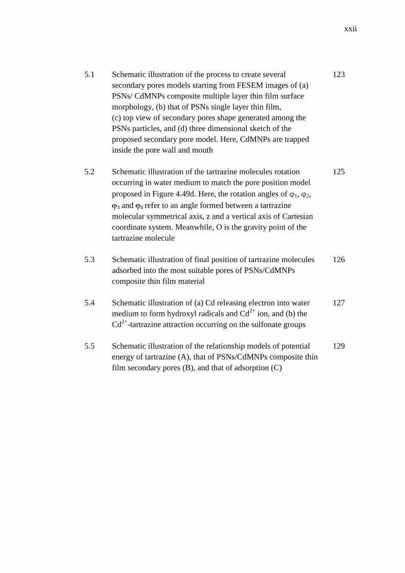
5.1 Schematic illustration of the process to create several
secondary pores models starting from FESEM images of (a)
PSNs/ CdMNPs composite multiple layer thin film surface
morphology, (b) that of PSNs single layer thin film,
(c) top view of secondary pores shape generated among the
PSNs particles, and (d) three dimensional sketch of the
proposed secondary pore model. Here, CdMNPs are trapped
inside the pore wall and mouth
123
5.2 Schematic illustration of the tartrazine molecules rotation
occurring in water medium to match the pore position model
proposed in Figure 4.49d. Here, the rotation angles of 1, 2,
3 and 4 refer to an angle formed between a tartrazine
molecular symmetrical axis, z and a vertical axis of Cartesian
coordinate system. Meanwhile, O is the gravity point of the
tartrazine molecule
125
5.3 Schematic illustration of final position of tartrazine molecules
adsorbed into the most suitable pores of PSNs/CdMNPs
composite thin film material
126
5.4 Schematic illustration of (a) Cd releasing electron into water
medium to form hydroxyl radicals and Cd2+
ion, and (b) the
Cd2+
-tartrazine attraction occurring on the sulfonate groups
127
5.5 Schematic illustration of the relationship models of potential
energy of tartrazine (A), that of PSNs/CdMNPs composite thin
film secondary pores (B), and that of adsorption (C)
129

xxiii
LIST OF SYMBOLS
% v/v Volume–volume percentage, that is equal to the volume of
solute in milliliter per its 100 milliliter solution.
% w/v Weight-volume percentage, that is equal to the mass of solute
in gram per its 100 milliliter solution..
% w/w Weight-weight percentage, that is equal to the mass of solute
in gram per its 100 gram solution. This is the same as weight
percentage term.
% PSNs Weight percentage of PSNs particles
Tartrazine adsorption proportional constant
(pi) bonding Overlapping p orbital of bonded atoms
(pi) constant 3.14159
1, 2, 3, 4 Rotation angle (0–360o) of tartrazine molecules on its mass
center
1, 2, 3, 4 Standing angle (0–90o) of secondary pore
t Temperature different between two states in oC
3–p three PSNs particles
4–nop four–non–ordered PSNs particles
4–op four–ordered PSNs particles
5–p five– PSNs particles
Ǻ Angstrom, that is equal to 10–10
meter
A1 Triangle–wide peak area of ATR–FTIR spectra in 3125–3000
cm–1
wavenumber range

xxiv
A2 Triangle–wide peak area of ATR-FTIR spectra in 1400–1300
cm–1
wavenumber range
AMAP1µLPSNs The amount of metal atomic particle loaded in 1µL volume of
its associated PSNs dispersion.
APPSNs1µL The amount of PSNs particles that exist in its 1µL dispersion
AW Atomic weight of metal atomic particle
b Langmuir constant that represents adsorption binding site
affinity of an adsorbent
Cp Specific heat capacity at constant pressure
e electron
EA Potential energy of tartrazine
EB Potential energy of secondary pore of PSNs/CdMNPs
composite thin film
Ebad Energy barrier of adsorption of secondary pore of
PSNs/CdMNPs composite thin film
Ebad_Cd Energy barrier of adsorption due to Cd metal nanoparticles
existence
EC Potential energy of adsorption process
eV electron volt
GMPS Mass in gram unit of metal precursor salt required to prepare
its solution stock of 1 M 10 mL
KF Freundlich constant that represents maximum capacity of
adsorption of an adsorbent
M Molar or mole per liter or mmol per milliliter
n Freundlich constant that represents intensity of adsorption of
an adsorbent
NA Avogadro number, i.e. constant number of 6.023×10²³
particles per mole of mass itself.
NaBH4 Sodium borohydride
194

xxv
QCdMNPs Calor absorbed by CdMNPs
Qo Langmuir constant that represents maximum capacity of
adsorption of an adsorbent
QPSNs Calor absorbed by PSNs
QPSNs/CdMNPs Calor absorbed by PSNs/CdMNPs
Qr Calor ratio
ra PSNs radii in average
rb Metal–covered PSNs radii
rc PVP–stabilized metal–covered–PSNs radii
rm Metal atomic particle radius in average
SAPSNs Surface area of PSNs particle
T↑ The Real heat
Ta The amount of adsorbed tartrazine in µmol
Tgd The amount of degradable adsorbed tartrazine in µmol
tm: Thickness of covering metal
TMAP Total amount of metal atomic particles covered fully a surface
area of each PSNs particle
tMAPS Thickness of metal atomic single layer covered the associated
PSNs particle
TMCPSNs Thickness of metal covering a PSNs surface
Tngd The rest amount of non degradable adsorbed tartrazine in µmol
To Original concentration of Tartrazine solution in % w/v
Tr The rest amount of non–adsorbed tartrazine in µmol
ts Thickness of PVP stabilizer
VMAP Volume of metal atomic particle
VMAPSL Volume of metal atomic single layer on a surface of
PSNs particle

xxvi
W Watt
wt, so, et, nr, up and
lo
The direction of PVP molecule on stabilizing metal-covered
PSNs, where wt, so, et, nr, up and lo stands for west, south,
east, north, upper and lower respectively.
Ε Porosity of solid-phase material
η Tartrazine degradation proportional constant

xxvii
LIST OF ABBREVIATIONS
ATR-FTIR Attenuated total reflectance-Fourier transform infrared
aDL Width area of double layer closed–packed periodical spheres
arrays
aSL Width area of single layer closed–packed periodical spheres
arrays
AW Atomic weight
CAC Commercial activated carbon
Cap Capric acid
CCB Chitosan–coated bentonite
Cd Cadmium
Cd(NO3)2.4H2O Cadmium nitrate–4–hydrate
CdMNPs Cadmium metal nanoparticles
cm centimeter
CMC Ceramic matrix composite
CSAC Coconut shell activated carbon
dDL Interpore distance in double layer closed–packed periodical
spheres arrays
DI Deionized
DLPSA Double layer closed–packed periodical spheres arrays
dPSNs Density of PSNs emulsion or PSNs particles mass per 1 cm3
its volume

xxviii
dSL Interpore distance in single layer closed–packed periodical
spheres arrays
DTA Differential thermal analysis
EDX Energy dispersive X–ray
FESEM Field emission scanning electron microscope
GAC Granular activated carbon
GMPS Mass in gram of metal precursor salt
ICP Inductive couple plasma
IUPAC International union of pure and applied chemistry
J joule
kJ kilo joule
L liter
MAC Maximum adsorption capacity
mg milligrams
min minutes
mL milliliter, that is equal to cm3
mM millimolar or mmole per liter
MMC Metal matrix composite
mmol millimole
µ mikron
µmol mikromole
MNPs Metal nanoparticles
MolMAP Mole amount of metal atomic particles required to prepare its
solution stock to fully cover 1.5810 1014
PSNs particles
MPM Metal precursor mass in gram for the preparation of 1M
10 mL solution stock

xxix
mtorr Mili torr, that is equal to 1 atmosphere pressure.
MWMPS Molecular weight of the associated metal precursor salt
MWPSNs Weight average molecular weight of PSNs
nm nanometer, that is equal to 10–9
meter
NM non-metal
nmol nanomole, that is equal to 10–9
mole
PMC Polymer matrix composite
PS Polystyrene
PSNs Polystyrene nanospheres
RF Radio frequency
RIE Reactive ion etching
SAPSNs Surface area of a PSNs particle body
sccm second per cubic centimeter
SEM Scanning electron microscope
SLA Scanned laser annealing
SLPSA Single layer closed–packed periodical spheres arrays
TEM Tunneling electron microscope
TFL Thin film layer
Tg Glass transition temperature
TG Thermo gravimeter/thermo gravimetri
UV-Vis Ultraviolet-visible
VEPSNs Volume of PSNs suspension which is introduced for
preparing PSNs–metal colloids
VMAP Volume of metal atomic particle
VMAPSL Volume of metal atomic single layer on a surface of PSNs

xxx
VMP Volume of a metal atomic particle
VMTPSNs Volume of metal thickness covered a PSNs surface
VSPSNs Volume of PSNs suspension which employed to prepare an
aqueous colloidal PSNs–metal nanoparticles

xxxi
LIST OF APPENDICES
Appendix Title Page
A The Previous Works on Composite/Nanocomposite Thin
Film Material
152
B The Algorithm Flow Chart of the Synthesis of Self-
Assembled PSNs/CdMNPs Composite Thin Film for Its
Application as Adsorbent and Catalyst
154
C Calculation Method of the Determination of the Amount of
PSNs/CdMNPs Ratio
156
D The Result of the Calculation of the amount of Chemicals
Required for the Preparation of 1M 10 mL Cd metal
Precursor Solution Stock to cover 1 µL 1%w/v PSNs (10 µL,
0.1% PSNs) of 200 nm size
160
E Reagents, Materials, Equipments and Analytical Instruments 161
F FTIR Spectra Assignment 165
G ATR-FTIR Spectra Assignments of Pristine PSNs Particle,
PSNs/MNPsCd Composite, and Tartrazine Molecule
166
H Various ATR-FTIR Spectra of Pristine PSNs/MNPsCd for
Various Time Adsorption Test
168
I The Meaning of the Wide Area Border of the ATR–FTIR
Spectra
174
J The Coordinates Points of the Adsorption Curve for the
Tartrazine shown in Appendix I
176
K Chemical and Physical Properties of Elements Involved in
this Research
178

1
CHAPTER 1
INTRODUCTION
1.1 Background
Recently, composite materials have attracted a great deal of attention due to its
advantageous properties for various applications in the development of products in
various aspects of human life. It is because the properties of composites are closely
related to their constituent materials which are significantly different physical or
chemical properties, and the materials work together to provide the composite unique
properties [1–4]. Among of the composites materials, specifically, a porous polymeric
matrix composite (PMC) of metal nanoparticles (MNPs) has shown very useful
adsorptive and catalytic properties. They have a variety of application in the fields of
sensors, controlled-drug-released agents and column-packing material [5–8], refining
and chemical industry, fuel cells and photovoltaic cells [9], air purification, sewage
disposal, environmental pollution control and medicine filtering [10–12] and so on.
The physical and chemical properties of the composites are significantly enhanced
when one of its constituents is within 1–100 nm in size, namely nanocomposite
materials [2,13–14]. In this situation, the nanocomposites have special physico–
chemical properties due to the quantum size effect and high specific surface area to
volume ratio which are different from their atomic or bulk counterparts [15–17].

2
Nanoparticles of the transition metal oxides (TiO2, CuO, ZnO)[1,18,19] and
the transition metals (Ag, Au, Co, Pt, Fe, Zn, Cd)[7,8,20–22] are widely used as the
constituents for the polymer/MNPs composite-based porous materials manufacturing
for diverse applications. For instance, Jundale and his co-workers [1] have
synthesized polyaniline/CuO nanocomposite for an optical and electrical transport
material. Sandoval et al. [18] have synthesized a novel extruded polystyrene/TiO2
nanocomposite material to degrade dye. Mu and his research team [22] have
synthesized polyimide/ZnO nanocomposite for photoluminescence material. Another
group of researchers [23] has synthesized polystyrene microfibers/CdS
nanocomposite for electrical and optical material. Several previous works focused on
composite/nanocomposite materials are listed in Appendix A.
Almost all of the polymer matrixes mentioned above were porous solid-phase
structure [1,19,22,23] of intraparticle pores type [24–26]. This is a big problem for the
development of porous material engineering because the intraparticle pores are very
difficult to be generated. The intraparticle pores generation always occur through
polymerization process that requires many kinds of chemicals and this results in the
difficulties to manufacture intraparticle pores-based porous materials with
controllable size and shape [13,27,28]. In this context, it has been accepted that size,
shape, and distribution of the pores are three very important factors in generating
characters of the porous nanocomposite materials [15,18].
To date, many studies of the porous materials are commonly employing
intraparticles pores-based porous materials [13,29] rather than interparticle pore–
based ones. This is because the first type of material is more dominant in surface area
compared to the associated solid materials formed, as they are smaller in size, that
provides higher total surface area to volume ratio than the second type of material
[24].
However, uncontrollable size, shape and uniformity of the intraparticle pores
become a very serious problem for the porous nanocomposites‟ fabrication and
development. It is because intraparticle pores generation always occur through
polymerization process which requires many kinds of chemicals [13,27,28].
Therefore interparticle pores are considered more controllable in size and shape to
fabricate porous composite-based materials. In this research, aqueous monodispersion
of polystyrene nanosphere (PSNs) of 200 nm size in average is used as polymeric

3
matrix for the intended porous composite thin film material. Study of the
relationships of the size and shape with their adsorption and catalytic properties will
be focused on the interparticles pores–based porous composite materials.
Furthermore, the terms of primary pores and secondary pores will be used in this
thesis instead of intraparticle pores and interparticle pores respectively.
Adsorption and catalytic properties of the porous material are easier to be
studied when it is in a solid phase. In particularly thin film solid–phase materials, they
are commonly prepared as a colloidal system in the most suitable liquid medium to
obtain nanoscale–size, shape and particles uniformity [2,30–32]. In the colloidal
system, there are at least two kinds of components which are a dispersing medium as
a continuous phase (including colloidal stabilizer) and dispersible particles of about 1
nm–1 µm in size [13,33–35].
Deposition of the colloidal system mentioned above on a convenient solid
support material (noted as substrate) leads to self-assembly process [2,36–39].
However, cadmium metal nanoparticles (CdMNPs) have never been applied as a
counterpart component in the fabrication of porous polymeric matrix composite
material. It is commonly used either as CdS or CdSe for light-emitting device and
solar cells that is incorporated into the polymer [40,41]. Therefore, we use CdMNPs
metal nanoparticles instead of CdS and CdSe as a counterpart component to fabricate
PSNs/CdMNPs composite thin film material with secondary pores generated among
the PSNs/CdMNPs composite particles. This is because the study focused on the
relationship between the size and shape of the secondary pores and its adsorption and
catalytic properties rather than the electronic and electrical properties.
On the other hand, tartrazine (trisodium–5–hydroxy–1–(4–sulfonatophenyl)–
4–(4–sulfonato–phenylazo)–H–pyrazol–3–carnoxylate)[42] is one of the synthetic
dyes widely used in food; textile and paper coloring processing which has been
reported could cause health problems at the level of bronchia and skin [43,44],
allergies, asthma, migraine, blurred vision, thyroid cancer, mutagenic and lupus
[42,45,46]. Tartrazine can endanger human life if it cannot be managed properly
during the production and disposal process. At present, the most common treatment
method for removal of tartrazine in waste water stream is adsorption [45–47] and
oxidation catalytic degradation using metal oxide (TiO2) or hydrogen peroxide (H2O2)
[43–44,48]. By these considerations, tartrazine was used to investigate the adsorption

4
and catalytic properties of the fabricated secondary pores of PSNs/CdMNPs
composite thin film material.
1.2 Problem statement
The pore structure of a porous nanocomposite material is revealed from both
intraparticle voids (primary pores) and interparticle voids (secondary pores) [24–26].
The shape and size of primary pores as well as pore uniformity are very difficult to be
controlled. It is because they are generated from the polymerization reactions which
require various kinds of chemicals (initiator, terminator, catalyst and appropriate
medium) simultaneously employed [1,6,18,22,49–51]. On the other hand, the
chemical as well as physical properties, particularly adsorption and catalytic
properties of porous nanocomposite material are strictly determined by size, shape,
and uniformity of not only the particles themselves but also the generated pores
[2,5,52,53]. Therefore, qualitative classification of primary pores based on the size
and shape has been performed [24–26]. They become micropores (the width is
smaller than 2 nm), mesopores (the width is between 2 and 50 nm), and macropres
(the width is larger than 50 nm), or they are classified as cylindrical shape, ink-bottle
shape, and funnel shape. However, secondary pores particularly in terms of the size
and shape in correlation to the adsorption and catalytic properties of the associated
materials have not been intensively studied yet as indicated by the limited number of
papers published about this phenomenon [5,13,24,53]. As long as the time,
interparticles voids or secondary pores of spherical shape materials were just utilized
for the fabrication of nanostructure materials that commonly applied in lithography
field [54,55].
In nanomaterial science and engineering point of view, secondary pores can be
utilized as a useful adsorbent since they have loading capacity for adsorptive
materials are much bigger than that of primary pores. In addition, the secondary pores
can also be used to embed or to incorporate any catalytic material for generating
catalytic properties so that the associated incorporated material can be used as

5
catalyst. Therefore, the study of secondary pores of polystyrene nanospheres-based
materials in relation to adsorption and catalysis is performed in this research.
For the study, the problems are as follows:
i. How can secondary pores of polystyrene nanospheres-based materials be
synthesized and fabricated?
ii. How is the secondary pores surface morphology of the fabricated materials and its
physical and chemical stability?
iii. How can the adsorption and catalytic properties of secondary pores of the
fabricated polystyrene nanospheres-based materials be investigated?
Secondary pores are also a very important factor which significantly influences the
quality of any fabricated porous material [5,24–26,53]. Thus, the novelty and
contributions of the study is about secondary pores: synthesis, fabrication,
characterization, properties, and possibility of application as adsorbent and catalyst in
the removal of tartrazine in correlation to their size, shape and distribution/uniformity.
1.3 Hypothesis
With regards to the definition of interparticle voids (secondary pores) [24–26] and a
few references as stated in the previous section [1,6,18,49–51], the hypotheses are as
follows:
i. PSNs-based secondary pores would be fabricated directly from aqueous colloidal
PSNs particles without polymerization reactions by gently dropping the colloidal
solution onto a hydrophilic silicon wafer surface, and the size and shape of the
secondary pores could be enlarged significantly by cadmium metal nanoparticles
(CdMNPs) that aggregate deposit between every two PSNs particles.
ii. Physical and chemical stability of the fabricated secondary pores of
PSNs/CdMNPs nanocomposite thin film can be increased by CdMNPs.
iii. The capability of adsorption and catalysis properties of the fabricated secondary
pores of PSNs/CdMNPs nanocomposite thin film can be investigated by using
tartrazine as a water-soluble organic pollutant model.

6
1.4 Aim
To fabricate polystyrene nanospheres/Cd metal nanoparticles (PSNs/CdMNPs)
composite thin film material, explore its physical and chemical properties and apply it
for the adsorption of water-soluble colored organic molecules, tartrazine and study of
typical catalytic performance of the material.
1.5 Objectives
The objectives of this study are as follows:
i. To fabricate secondary pores of PSNs/CdMNPs composite thin film material and
investigate their specific surface morphology to determine their size and shape.
ii. To investigate the secondary pores surface morphology and stability of the
fabricated PSNs/CdMNPs composite thin film material.
iii. To investigate the adsorption and catalytic properties of secondary pores of the
fabricated PSNs/CdMNPs composite thin film material for removal of tartrazine.
1.6 Scope
In order to achieve the first objective, synthesis of PSNs/CdMNPs composite thin
film material via aqueous colloidal system was carried out. It is because the size,
shape, and uniformity of PSNs/CdMNPs particles would be generated in a colloidal
system [56]. In this colloidal system, Cd metal precursor is reduced to become Cd
metal nanoparticles using either chemical reagent (NaBH4) or physical treatment
(high frequency ultrasound of 40 kHz for 45 minutes) [50,57,58]. Subsequently, the
desired secondary pores of PSNs/CdMNPs composite thin film material were
fabricated on a hydrophilic silicon wafer of 1 cm 1 cm size using gentle dropping
method. FESEM was used to explore the surface morphology of the fabricated

7
secondary pores. This surface morphology provides a lot of information about the
size, shape and distribution of the secondary pores.
For the second objective, surface morphology of the fabricated secondary
pores was explored using FESEM (JEOL JSM–7600 SM17600053, Japan). The
success of CdMNPs incorporation onto PSNs particles was confirmed using Energy
Dispersive X–ray (EDX) spectrometer (JEOL JSM–7600 SM17600053, Japan). In
addition, physical stability of secondary pores of the fabricated PSNs/CdMNPs
composite thin film were investigated by continuous laser irradiation of 633 nm
wavelength whereas chemical stability of the secondary pores were investigated by
oxygen/argon reactive ion exchange (O2/Ar RIE).
As for the third objective; the optimum size, shape and distribution of the
fabricated secondary pores of PSNs/CdMNPs composite thin film materials were used
to adsorb tartrazine molecules through incubation method in batch system for a series
of time: 5, 10, 15, 20 and 25 minutes under visible light lamps of the laboratory at
ambient temperature and pressure. The adsorbed tartrazine in the secondary pores was
confirmed by using ATR-FTIR spectrometer (LR 64912C, N3896, Perkin Elmer,
U.S.A) equipped with a universal ATR sample holder and spectrum express FTIR
software V1.3.2 Perkin Elmer LX100877–1. The adsorption characteristics of the
pores were evaluated using both Langmuir and Freundlich isotherm adsorption. The
catalytic characters were evaluated based on the curve trend correlated between the
amount of tartrazine and adsorption time.

8
CHAPTER 2
LITERATURE REVIEW
2.1 Introduction
In this chapter, a research study on the synthesis of self-assembled polystyrene
nanospheres/cadmium metal nanoparticles (PSNs/CdMNPs) composite thin film for
its application as an adsorbent and catalyst in the removal of tartrazine will be
thoroughly reviewed.
2.2 Pores Classification
Based on reference [24–26], pore structure of solid materials can be classified into
two main types, intraparticle voids (primary pores) and interparticle voids (secondary
pores). In particular intraparticle voids, they can be distinguished further based on
their size, shape, and interconnection to the surface of the associated particle.
Furthermore, based on the size of the pores, a pore is classified into three
types [5,24–26,59]:
i. Micropores that have widths smaller than 2 nm,
ii. Mesopores that have widths between 2 and 50 nm, and
iii. Macropores that have widths larger than 50 nm.

9
In addition, another size of 1–100 nm can be classified as nanopores since the size
range is commonly used as a parameter of nano-scale-size material [2,14,60–62].
Currently, gigaporous material with pore size of 300-500 nm is also known [63].
Based on the shape of the pores, a pore can be further classified into three types [24]:
i. Cylindrical shaped pores,
ii. Ink–bottle shaped pores, and
iii. Funnel shaped pores.
Based on the pore interconnection to the surface, a pore can be classified into
two types [24]:
i. Closed pores, and
ii. Opened pores.
Closed pores are defined as pores which are totally isolated from their
neighbours, they have no access to the surface of the particle body. On the other hand,
opened pores are defined as pores which have continual channel of communication
with the external surface of the particle body, it may open only at the end (noted as
blind pore or dead-end pore), or may open at two ends (noted as through pore) [24].
In general, schematic illustration of the primary pore structure and configuration
model is depicted in Figure 2.1. In special cases, schematic illustration of the primary
pore structure and configuration model generated in PSNs particle body was proposed
by Wibawa et al. (2011)[58] as depicted in Figure 2.2.
Figure 2.1: Schematic illustration of primary pores classification based on the
interconnection to the particle surface, and shape. (a) closed pores; (b, c, d, e) opened
pores; (c, e, f) cylindrical shaped pores; (b) ink–bottle shaped pores;
(d) funnel shaped pores [24]
f

10
Figure 2.2: Schematic illustration of primary pores models revealed in PSNs particle
body of 200 nm size. (a) India traditional trumpet–like pore; (b) face–to–face junction
bottle neck–like pore; (c) randomly irregular form pore, and
(d) straightforward pipe–like pore
Accordingly, interparticle pore (secondary pore) generated among the PSNs particle
bodies can be illustrated as shown in Figure 2.3.
Figure 2.3: Schematic illustration of secondary pores models revealed
among four PSNs particle bodies of 200 nm size
20
0 n
m
a b c
d
Secondary pore

11
The pores and particle size, shape and distribution are the most important parameters
for the properties of solid–phase materials in nano–scale–size from 1 nm up to 1µm
size range [24–26,64]. It is because within the size, solid-phase materials are
dominated by surface properties, including surface area and electrical charge rather
than chemical composition of the materials [60]. Interfacial properties are more
important for the smaller sizes as the consequence of the mass (atoms) would be at
the surface of the particles compared to the bigger sizes [65].
Furthermore, the pore structure of solid-phase materials becomes a main
parameter for the porosity (ε) of the associated materials. Porosity is defined as ratio
of the total pore volume Vp including opened pores and closed pores to the apparent
volume V of the particle or powder (excluding interparticles voids) [24–26,62]. It is
clear that each typical pore provides specific roles that are different from each other in
their interactions with other things such as fluids, lights, sounds, and so on. For
example, closed pore (Figure 2.1a) is intensively facile for many processes of sound,
heat, and light absorptions so that they are beneficial for the manufacturing of
vibration dumping material and heat, light even electrical insulators [24–26,62]. Open
pores with dead-end are noted as blind open pores (Figure 2.1b and f) which facilitate
many processes of adsorptions and catalysis effectively [24–26,62]. In addition, open
pores without dead-end are noted as through pores (Figure 2.1c) which facilitate
many processes of mass transportation so that they are beneficial in filtration and any
material exchange processes [24,62,63].
Accordingly, it can be concluded that pore size and shape as well as their
typical distribution are very critical factors in the design and manufacturing process
for porous solid nanomaterials for specific applications.
2.3 Primary pores and secondary pore of PSNs/CdMNPs composite thin
film
The generation of primary pores and secondary pores of PSNs-based porous materials
is also a very critical factor for the development of porous material techniques. In this
section, the generation of the typical pores is reviewed in detail.

12
2.3.1 Primary pores of PSNs/CdMNPs composite thin film
Based on the references [24–26], primary pores (intraparticle voids) of
PSNs/CdMNPs composite thin film can be generated by random scaffold of the
polystyrene structure network. It has been widely known that polystyrene molecule
can exist in three conformation structures due to the rotation of its skeleton carbon-
carbon single bonds to synchronize the most stable structure with minimum energy
[66–68]. The three conformation structures of polystyrene that are well known are
isotactic, syndiotactic and atactic as depicted in Figure 2.4 [68]. The isotactic and
syndiotactic structures usually refer to either crystalline or fibber material whereas
atactic is usually amorphous [67].
Figure 2.4: Three conformational structures of polystyrene skeleton chain
In the case of syndiotactic crystalline structure, it can be , , and
crystalline forms depending on the process for getting the crystals [66,69,70]. The
most important feature of this phenomenon is its molecular conformational structure.
In this context, and crystalline forms contain trans-planar zigzag (T4)
conformation that can be obtained by cooling the melted glass or by heating the glass
[69]. Whereas and crystalline forms contain s(2/1)2 helical chains generated by

13
TTGG conformational sequences that can be obtained by dissolving the polymer into
organic solvent ( form) and subsequently purging away the solvent from the polymer
by heating ( form) [66,70]. Illustration of the molecular chain conformation of the
crystalline phases of syndiotactic polystyrene is provided by reference [69], Figure
2.5.
Figure 2.5: Molecular chain conformation of crystalline phases of
syndiotactic polystyrene [69]
Unfortunately, it still does not provide a clear representation of primary pores
generated in PSNs particles particularly in terms of the primary pore shape despite
their channels being about 1.5-3.0 nm in size [71]. Researchers [58] have proposed
four kinds of valuable models for open primary pores‟ shape that are possible
revealed in the PSNs particles body. The pore models have also been developed based
on the capability of multiple random bending and folding of the polystyrene chain
frame work. Schematic illustration of the individual primary open pores‟ models that
are possibly revealed in the PSNs particles body is depicted in Figure 2.6.

14
Figure 2.6: Schematic illustration of the individual primary pores models revealed in
PSNs particle body of 200 nm size proposed by Wibawa et al. (2011)[58]
Figure 2.6a shows an Indian traditional trumpet-like model primary pore, 2.6b
face-to-face junction bottle neck–like model primary pore, 2.6c randomly irregular
form model, and the last is 2.6d straightforward pipe-like model primary pore. Figure
2.6e represents PSNs particle body with the all primary pore models. The most
interesting part of the proposal is the introduction of new terms of nano-sunken and
nano-wells that are responsible for effectively binding sites in adsorption and catalytic
processes. By using the above models, it is easier to understand that the highest
capacity and capability of adsorption will occur on a pore model of irregular form,
Figure 2.6c because of the five binding sites which exist therein. On the contrary, the
lowest capacity and capability in adsorption will occur on a straightforward pipe-like
pore model because it has only one binding site as proposed by Wibawa et al. [58].
2.3.2 Secondary pores of PSNs/CdMNPs composite thin film
Based on the reference [24–26], structure of secondary pores (inetrparticles voids) of
PSNs/CdMNPs composite thin film would be generated by the ordered and
disordered arrangement of the PSNs particles deposited properly on the surface of
hydrophilic silicon wafer. In relation to that, each of the researchers [37–39] showed
unique secondary pore surface morphology which revealed inter polystyrene particles
20
0 n
m
1 2 3 4 1 2 3
4
(a) (b) (c) (d) (e)
: Binding site sunken and wells

15
body of various sizes, 100-500 nm deposited on a solid support material were
provided by references [37–39] as seen in Figure 2.7.
Figure 2.7: FESEM images of (a) secondary pores revealed inter PSNs particles body,
multilayer PSNs thin film deposit [37]; (b) ordered single
layer PSNs thin film deposit [38]; and (c) disordered
single layer PSNs thin film deposit [39].
Figure 2.7a displays various sizes and shapes of secondary pores which
revealed inter PSNs particle bodies forming interesting porous nanomaterial structure.
The secondary pores structures can be justified clearly by Figure 2.7b and 2.7c where
every three close-packed PSNs particles generated triangular shape secondary pores.
Figure 2.7c demonstrated the arbitrary configuration of PSNs particles forming a few
secondary pores generated by four or five close-packed PSNs particles. If any metal
nanoparticles (MNPs) were inserted properly between every two close-packed PSNs
particles, the pores will become larger and the capacity of adsorption can be enhanced
significantly. In correlation to the definition of nanocomposite material [2,4,14], it
means a new useful material namely porous nanocomposite thin film that has
capability of adsorption and catalysis can be manufactured properly from PSNs and
MNPs particles.
Furthermore porosity of the material can be justified if their volume ratio of
pore space to the total volume of the associated material is between 0.20–0.95 [62].
According to the structure and composition of porous material summarized in Table

16
2.1 [62]; the highest porosity of more than 0.6 commonly belongs to polymer-based
materials, so that it is possible to include PSNs particles-based nanocomposite
materials.
Table 2.1: Structure and properties/characters relationship of some porous materials
based on their main components [62]
NO. CHARAC-
TERISTIC
MATERIALS
POLYME-
RIC
CAR-
BON GLASS
ALUMI-
NA
SILICA-
TE
OXIDES METAL
1 Chemical
stability
Low-
medium
High High High Very high High
2 Costs Low High High Low-
medium
Medium Medium
3 Life Short Long Long Medium-
long
Long Long
4 Permeability Low-
medium
Low-
medium
High Low Low-
medium
High
5 Pore size Meso up to
macro
Micro up
to meso
Meso up
to macro
Micro up
to meso
Micro up
to meso
Meso up
to macro
6 Porosity > 0.6 0.3–0.6 0.3–0.6 0.3–0.7 0.3–0.6 0.1–0.7
7 Strength Medium Low Strong Weak Weak-
medium
Strong
8 Surface area Low High Low High Medium Low
9 Thermal
stability
Low High Good Medium-
high
Medium-
high
High
Table 2.1 shows the relationship of porosity and other properties to the structure and
composition of nanocomposite material. Here, for example, organic/inorganic
polymeric-based material belongs to meso up to macro pores size, low surface area,
porosity > 0.6, low up to medium in permeability, medium in strength, low in thermal
stability, low up to medium in chemical stability, low cost and short living time. On
the other hand, oxides-based materials possessed meso up to macro pores size,
medium surface area, porosity 0.3-0.6, low up to medium in permeability, weak up to
medium in strength, medium up to high in thermal stability, very high chemical
stability, medium cost and long living time [62].
Specifically, valuable secondary pores-based porous material can be
fabricated by means of incorporating CdMNPs to PSNs particles as reported by
Wibawa et al. (2011)[58]. The incorporated metal will promote hypercrosslinking of

17
the polymer chain and add unique physical properties such as responsiveness to
mechanical, optical, thermal and sound barrier, magnetic, electric stimulation [72].
2.4 Synthesis and fabrication of PSNs/CdMNPs composite thin film materials
Secondary pores of PSNs/CdMNPs composite material can be generated only from its
aqueous colloid coated on a solid support material. Accordingly, there are two steps
to obtain nanostructure secondary pores of the PSNs/CdMNPs composite material.
The first step is the synthesis of aqueous colloidal PSNs/CdMNPs composite. The
second step is fabrication of secondary pores-based porous PSNs/CdMNPs composite
thin film material on a solid support material through deposition method of the
colloid. This section describes the two steps.
2.4.1 Synthesis
Referring to previous researches [2,73], PSNs/CdMNPs secondary pores-based
porous nanocomposite thin film material can be synthesized by blending Cd metal
precursor with numerous PSNs organic polymers. Various polystyrene-based
nanocomposite materials had been synthesized using the blending method. Sometimes
the blending was performed in solid-phase medium instead of liquid/aqueous
medium. For example, silica gel microspheres encapsulated by imidazole
functionalized polystyrene (SG–PS–azo–IM) was synthesized and characterized to
adsorb transition metals with the highest adsorption capacity for Au(III) from aqueous
solution [74]. Polystyrene/carbon nanotubes composites were synthesized by
emulsion polymerization with non-covalent and covalent functionalization [75].
Polystyrene/multiwalled carbon nanotubes composites with individual-dispersed
nanotubes and strong interfacial adhesion were synthesized in organic mediums of
tetrahydrofuran and ethanol [76].
Furthermore, referring to literature [77–79], it can be well understood that the
most important things in the synthesis of PSNs/CdMNPs nanocomposites materials is

18
the reduction process of metal precursor used where positive charges ions (cations)
become metal (zero valence ions). Many methods have been well known for the
reduction of metal precursors which can be distinguished between chemicals methods
and physical methods [80]. In this context, chemical methods mean the reduction was
performed by employing chemical reducing agent of organic molecule such as N,N-
dimethylformamide (DMF) [77,78,81] and inorganic molecule such as NaBH4 [82] to
reduce metal precursor to its metal atom synchronically in a suitable solvent. In
contrast, physical reduction methods means that the reduction was performed using
physical actions such as high frequency ultrasound of 20 kHz–10 MHz [83,84],
microwave irradiation [85–87], gamma (γ) ray radiation [6,88] and so on. In this
viewpoint, researchers [80] reported that there were ten various methods of silver
nanoparticles preparation by means of reduction process which are well known today.
Physical reduction using high frequency ultrasound would produce metal
nanoparticles with lesser chemical contaminants compared to that produced by
chemical reducing agents [58,89]. It is also simpler and safer than other physical
reductions. In practice, the process of metal precursor reductions could be conducted
by means of either in-situ in which metal nanoparticles are generated in polymer
matrix or ex-situ in which metal nanoparticles that were previously synthesized are
incorporated in the polymer matrix [2,30,87,90]. In order to make it easy to
understand the difference of in-situ and ex-situ metal reduction process, a simple
schematic illustration of both reductions processes is depicted in Figure 2.8.
Figure 2.8: Schematic illustration of (a) ex situ reduction process of metal
precursor M+ to metal nanoparticles (MNPs) and (b) that of in situ one
Legend:
(a)
Physical treatments or
Chemical treatments
M+ M
M
Polymer matrix (b)
Physical treatments or
Chemical treatments
M+ M M
+ : Metal precursor
: Metal nanoparticles
(MNPs)
M
19
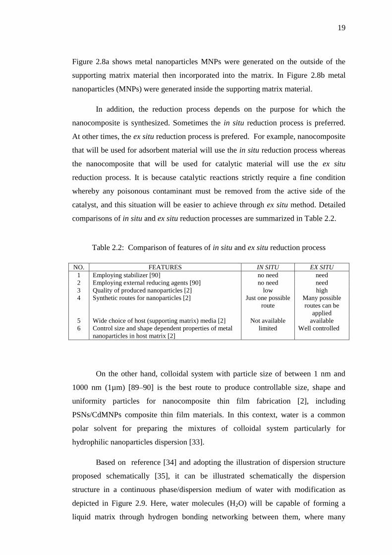
Figure 2.8a shows metal nanoparticles MNPs were generated on the outside of the
supporting matrix material then incorporated into the matrix. In Figure 2.8b metal
nanoparticles (MNPs) were generated inside the supporting matrix material.
In addition, the reduction process depends on the purpose for which the
nanocomposite is synthesized. Sometimes the in situ reduction process is preferred.
At other times, the ex situ reduction process is prefered. For example, nanocomposite
that will be used for adsorbent material will use the in situ reduction process whereas
the nanocomposite that will be used for catalytic material will use the ex situ
reduction process. It is because catalytic reactions strictly require a fine condition
whereby any poisonous contaminant must be removed from the active side of the
catalyst, and this situation will be easier to achieve through ex situ method. Detailed
comparisons of in situ and ex situ reduction processes are summarized in Table 2.2.
Table 2.2: Comparison of features of in situ and ex situ reduction process
NO. FEATURES IN SITU EX SITU
1 Employing stabilizer [90] no need need
2 Employing external reducing agents [90] no need need
3 Quality of produced nanoparticles [2] low high
4 Synthetic routes for nanoparticles [2] Just one possible
route
Many possible
routes can be
applied
5 Wide choice of host (supporting matrix) media [2] Not available available
6 Control size and shape dependent properties of metal
nanoparticles in host matrix [2]
limited Well controlled
On the other hand, colloidal system with particle size of between 1 nm and
1000 nm (1µm) [89–90] is the best route to produce controllable size, shape and
uniformity particles for nanocomposite thin film fabrication [2], including
PSNs/CdMNPs composite thin film materials. In this context, water is a common
polar solvent for preparing the mixtures of colloidal system particularly for
hydrophilic nanoparticles dispersion [33].
Based on reference [34] and adopting the illustration of dispersion structure
proposed schematically [35], it can be illustrated schematically the dispersion
structure in a continuous phase/dispersion medium of water with modification as
depicted in Figure 2.9. Here, water molecules (H2O) will be capable of forming a
liquid matrix through hydrogen bonding networking between them, where many

20
unique cages like cave in nano size are generated in the matrix, of which any
dispersed particles reside within the cages.
Figure 2.9: Schematic illustration of the structure of dispersion
system in water medium
Figure 2.9 shows that particle size ranges from 1–1000 nm for colloidal dispersion
system; less than 1 nm for molecular dispersion system that is called solution; and
more than 1000 nm for coarse dispersion system that is called suspension.
On the other hand, water molecules are also capable of solvation for any
positive and negative electrical charge particles in aqueous system. Solvation itself
could be defined as an interaction of a solute with the solvent, which leads to
stabilization of the solute species. One may also refer to the solvated state, whereby
an ion in a solution is grafted by solvent molecules [91–93]. By this definition, a
schematic illustration of the solvated state of positive ion and negative ion could be
drawn as depicted in Figure 2.10. It is very clear that the dispersion state and
Figure 2.10: Schematic illustration of (a) solvated state of positive ion and
negative ion, and (b) in water
H + H + O - - -
- H +
H + O - -
H + H + O - -
O - -
H +
H +
+
H + H + O - -
-
-
H +
H + O - -
H + H + O - - O - -
H +
H + _
(a) (b)
H+ H
+
O - -
H+
H + O
- -
O- -
H+
H +
H+ H
+
O- -
H+
H+
O - - H+ H
+
O- -
O- -
H+
H+
H+ H + O - -
H+ H
+
O- -
H+ H + O - -
-
-
-
- -
-
-
-
-
-
-
-
H+ H
+
O- -
O - -
H +
H+
H+ H + O - -
H+ H
+
O- -
H+ H + O - -
H+
H +
O - - H
+
H +
O - -
-
-
H+ H +
O- -
: Dispersed PSNs particles
: Water molecule
: Hydrogen bonding

21
solvated state are very different. Figure 2.10 shows the positive ion surrounded by
water molecules through electrostatic force attraction facilitated by water oxygen
atom and the associated positive ion, whereas the negative ion was surrounded by
water molecules through electrostatic force attraction facilitated by water hydrogen
atom and the associated negative ion.
Furthermore, various synthesis methods of CdS/Polystyrene nanocomposite
reported by a lot of researchers [39–41,94,95] could be adopted with little bit
modification to synthesize PSNs/CdMNPs composite material. The researchers used
colloidal stabilizers of either polyvinyl pyrrolidone (PVP) or citric acid [23,41,94,95].
However, in this research did not use colloidal stabilizer because of it can prohibit the
capability of adsorption and catalysis of the fabricated secondary pores.
2.4.2 Fabrication
Secondary pores of any solid material including PSNs/CdMNPs composite thin film
material could be generated on a solid support material (noted as a substrate) from its
suitable liquid colloidal [2,37–39]. In this situation, colloidal particles could initiate in
generating both lateral and vertical capillary force between them resulting in the
capability of self-assembly which leads to a colloidal thin film forming on a suitable
substrate [36]. A schematic illustration of the self-assembly process driven by
capillary force which was adopted from literature [36] as shown in Figure 2.11.
Figure 2.11: Schematic illustration of the self-assembly process drove by capillary
force. (a) Lateral capillary forces appear when there is disorderly motion of colloidal
particles in a liquid thick layer on a substrate, and (b) ordered state gives rise to
aggregation after the top of particles protrude from the liquid layer [36]
(a)
h1 2R
2R < h
Substrate
(b)
h2
2R
2R > h
Substrate

22
Figure 2.11a shows how pressure causes colloidal particles to settle down forming a
film while gravity keeps it planar. Figure 2.11b demonstrates a situation that
generated lateral capillary forces for a liquid thin film through self–assembly process
coinciding with disjoining pressure and three phase contact angle. In this figure, 2R is
the diameter (size) of the colloidal particle, h1: thick liquid layer and h2: liquid thin
layer. Explanation on how the capillary forces appear between colloidal particles had
been reported by researchers in reference [36] in detail.
Regarding the specific properties of colloidal system, it is well known that
colloidal routes offer numerous advantages for the synthesis of PSNs/CdMNPs
nanocomposite thin film material as it allows a good control over size, shape and size
distribution of the nanocomposite particles using relatively simple experiment
conditions [2,96]. In addition, many researchers proved that a solid nanocomposite
thin film material could be manufactured properly on a surface of suitable solid
support from its colloidal system by means of drop coating [97–99]; dip coating
[31,100–102]; spin coating [103–105]; or spray coating [106–108]. However, the
research objectives are about the adsorption phenomenon on secondary pores of the
PSNs/CdMNPs nanocomposite thin film materials. Therefore the drop coating
technique would be the most convenient technique for manufacturing them since the
colloidal PSNs/CdMNPs nanocomposite for generating multilayer secondary pores
can be produced in a more controllable quantity [97–99]. In this context, the size of
secondary pores in the pattern is proportional to the size of the sphere, and the sphere
size of 200 nm is a minimum threshold to get secondary pores of a good shape and
size [109].
In addition, the size of secondary pores generated from single layer close
packed periodical spheres arrays (SLPSA)(aSL) could be calculated approximately
through equation 2.1 while those generated from double layer close packed periodical
spheres arrays (DLPSA)(aDL) could be calculated approximately through equation
2.2. Interpores distance in SLPSA (dSL) could be calculated through equation 2.3,
whereas interpores distance in DLPSA (dDL) could be calculated through equation 2.4.
In this case, it had been shown that triangle–like pores and regular hexagonal pores
were revealed in the SLPSA and DLPSA respectively [54,55].

23
where D is the diameter of polystyrene nanospheres.
2.5 Characterization
A lot of common methods to characterize thin film materials are reviewed in this
section. The characterizations of the materials are as the follows.
2.5.1 Thermal properties
Thermal properties of the synthesized PSNs/CdMNPs composites were analyzed
using thermogravimetric analysis (TGA) and different thermal analysis (DTA). Under
TG analysis, the mass change/degradation of a sample as a function of temperature
could be known and well determined. The data output recorded from the TG is a TG
curve that correlates sample mass decreasing (∆m) against the temperature progress
(T). From the TG curve, the temperature decomposition or thermal stability and glass
transition temperature (Tg) of the measured sample [8,17,49,94] will be known. Glass
transition temperature itself can be defined as a temperature at which an amorphous
solid material becomes soft upon heating or brittle upon cooling. The glass transition
temperature will be lower than the melting point of its crystalline form [110]. In
relation to this, it is common for CdMNPs to be initially immobilized in the film
(2.1)
(2.2)
(2.3)
(2.4)

24
below the Tg of the associated polymer matrices. It is subsequently embedded into the
matrices at a temperature above Tg since the condition allows the polymer chain to
have a high degree of mobility [30].
On the other hand, DTA can be used to measure the difference in temperature
change between the sample and reference material both as a function of temperature.
The data output recorded from the DTA is a DTA curve that correlates the
temperature difference (∆T) against the temperature progress. Thus, from this DTA
curve the typical heat energy accompanied the chemical change of the sample: either
exothermic (heat released) or endothermic (heat absorbed) will be known [17,22,110].
Accordingly, it could be concluded that by comparing the data of TG as well
as DTA between PSNs/CdMNPs nanocomposite and pristine PSNs it could be known
that CdMNPs have been successfully incorporated into PSNs particles. In this
context, the quantity of calor (heat energy) required to decompose each material
aforementioned is necessary to be determined. For that, the relationship between
quantity of calor and temperature that is commonly used to explain the phenomena is
expressed in equation 2.5 [111], and this equation can be applied to calculate the calor
involved in the mass decomposition process.
Q = mCp∆t (2.5)
where Q is heat energy (commonly notes as calor) absorbed, m is mass of the
degraded material, Cp is specific heat capacity of the material and ∆t is the
temperature difference of the decomposition at the start and final decomposition
process that is noted as t1 and t2 respectively. In this case, calor quantity expressed in
equation 2.5 can be approximately determined based on the TG curves. Based on
the TG curves we can determine mass loss of the PSNs/CdMNPs composite as well as
that of pristine PSNs at every temperature of the decomposition process where the
calculation of calor quantity absorbed by the materials can be obtained.
The most important way to find out the thermal characters of aqueous
colloidal PSNs/CdMNPs composite is to investigate its homogenity. Therefore,
equation 2.5 needs to be developed to become a more applicable equation. Thus, a
valuable equation namely calor ratio (Qr) that is defined as in equation 2.6 where
QPSNs/CdMNPs, QPSNs, QCdMNPSs and mCdMNPSs are expressesd in equations 2.7, 2.8, 2.9 and
2.10 respectively can be introduced.
133
REFERENCES
1. Jundale, D. M; Navale, S. T; Khuspe, G. D; Dalavi, D. S; Patil, P. S; and
Patil, V.B. (2013). Polyaniline–CuO Hybrid Nanocomposites: Synthesis,
Structural, Morphological, Optical and Electrical Transport Studies. Journal of
Material Science:Mater Electron, 24, pp.3526–3535. DOI: 10.1007/s10854-
013-1280-5.
2. Ingrosso, C; Panniello, A. M; Comparelli, R; Curri, M. L. and Striccoli,
M.(2010). Colloidal Inorganic Nanocrystal Based Nanocomposites: Functional
Materials for Micro and Nanofabrication, Materials, 3, pp. 316-1352.
DOI:10.3390/ma3021316.
3. Yin, P; Xu, Q; Qu, R; Zhao, G; and Sun, Y. (2010). Adsorption of Transition
Metal Ions from Aqueous Solutions onto a Novel Silica Gel Matrix Inorganic–
Organic Composite Material. Journal of Hazardous Materials, 173, pp. 710–
716. DOI:10.1016/j.jhazmat.2009.08.143.
4. Smith,W.F. and Hashemi J. (2006). Foundations of Materials Science and
Engineering, 4th
.Ed. McGraw Hill International Edition, Singapore, pp. 8-15.
5. Vernimmen, J; Meynen, V. and Cool, P. (2011). Synthesis and Catalytic
Application of Combined Zeolite/Mesoporous Materials, Beilstein Journal of
Nanotechnology, 2, pp. 785-801. DOI: 10.3762/bjnano.2.87.
6. Yang, L; Ge, X; Wang, M; Song, L. and He, Xi. (2008a). Preparation of
Polystyrene-Encapsulated Silver Hollow Spheres via Self-Assembly of Latex
Particles at the Emulsion Droplet Interface, Materials Letters, 62, pp. 429-431.
DOI: 10.1016/j.matlet.2007.05.057.

134
7. Wang, C; Huang, C. L; Chen, Y. C; Hwang, G. L; and Tsai, S. J. (2008a).
Carbon Nanocapsules-Reinforced Syndiotactic Polystyrene Nanocomposites:
Crystallization and Morphological Features, Polymer, 49, pp. 5564-5574.
DOI: 10.1016/j.polymer.2008.09.057.
8. Wang, L; Wang, F; and Chen, D. (2008b). Fabrication and Characterization of
Silver/Polystyrene Nanospheres With More Complete Coverage of Silver
Nano-Shell. Materials Letters, 62, pp. 2153–2156.
DOI:10.1016/j.matlet.2007.11.078.
9. Xie, Z; Liu, Z; Wang,Y; Yang,Q; Xu, L. and Ding,W (2010). An Overview of
Recent Development in Composite Catalysts from Porous Materials for
Various Reaction and Processes, International Journal of Molecular Science,
11, pp.2152-2187. DOI:10.3390/ijms11052152.
10. Ai, L. Zhou, Y. and Jiang J. (2010). Article in Press: Removal of Methylene
Blue from Aqueous Solution by Montmorillonite/CoFe2O4 Composite with
Magnetic Separation Performance, Desalination (2010),
DOI:10.1016/j.desal.2010.08.004.
11. El-Latif, A. M. M. El-Kady, M. F. Ibrahim, A. M. and Ossman, M. E. (2010).
Alginate/Polyvinyl Alcohol - Kaolin Composite for Removal of Methylene
Blue from Aqueous Solution in a Batch Stirred Tank Reactor, Journal of
American Science, 6(5), pp. 280-292.
12. Zhihua, Z; Jun, S; Xingyuan, N; Yang, L. and Bo, W. Guangming W. Bin, Z.
Guoqing, W. Peiqing, W. Qingfeng, W. and Xixian, N. (2008). Benzene
adsorption properties of silica aerogel-fiber composite, 2nd IEEE International
Nanoelectronic Conference (INEC 2008), pp. 366-370.
13. Esfandabadi; Maleki, S; Pourmahdian, S; and Khoshkhoo, M. S. (2014).
Hollow Spherical Micro/Meso-Porous Silica Structure by Nanospherical
Sacrificial Polystyrene Templates. Journal of Reinforced Plastics and
Composites, 33(5), pp. 401-411. DOI: 10.1177/0731684413503049
14. Paul, D.R and Robeson, L.M.(2008). Polymer Nanotechnology:
Nanocomposites, Polymer, 49 (15), pp. 3187-3204.DOI:
10.1016/j.polymer.2008.04.017.

135
15. Chaudhari, S; Shaikh, T; and Pandev, P. (2013). A Review on Polymer TiO2
Nanocomposites, International Journal of Engineering Research and
Applications,3(5), pp. pp.1386–1391. ISSN : 2248–9622.
16. Guo, Z; Liang, X; Pereira, T; Scaffaro, R; and Hahn, H. T. (2007). CuO
Nanoparticle Filled Vinyl-Ester Resin Nanocomposites: Fabrication,
Characterization and Property Analysis. Composites Science and Technology,
67, pp. 2036–2044. DOI:10.1016/j.compscitech.2006.11.017.
17. Antolini, F; Pentimalli, M; Luccio, T. D; Terzi, R; Schioppa, M; Re, M;
Mirenghi, L. and Tapfer, L. (2005). Structural Characterization of CdS
Nanoparticles Grown in Polystyrene Matrix by Thermolytic Synthesis,
Material Letters, 59, pp. 3181-3187. DOI: 10.1016/j.matlet.2006.08.070.
18. Sandoval, H.G.M; Angarita, B.D.B; Torres, C. S. N.and Pedrozo, P. O. M.
(2013). Novel EPS/TiO2 Nanocomposite Prepared from Recycled Polystyrene,
Material Sciences and Applications, 4, pp. 179-185. DOI: 10.4236/
msa.2013.43021.
19. Grigalovica, A; Bochkov, I; Meri, R. M; Zicans, J; Grabis, J; Kotsilkova, R;
and Borovanska, I. (2012). The Effect of Nanosize ZnO on The Properties of
The Selected Polymer Blend Composites. IOP Conference Series: Materials
Science and Engineering,38, pp. 012053.
DOI:10.1088/1757-899X/38/1/012053.
20. Kanahara, M; Shimomura, M. and Yabu, H. (2014). Fabrication of Gold
Nanoparticles-Polymer Composite Particles with Raspberry, Core-Shell and
Amorphous Morphologies at Room Temperature Via Electrostatic Interactions
and Diffusion, Soft Matter, 10, pp.275-280. DOI: 10.1039/c3sm52077c.
21. Deniz, A. E; Vural, H. A; Ortaç, B; and Uyar, T. (2011). Gold Nanoparticle/
Polymer Nanofibrous Composites by Laser Ablation and Electrospinning.
Materials Letters, 65, pp. 2941-2943. DOI:10.1016/j.matlet.2011.06.045.
22. Mu, S; Wu, D; Qi, S; and Wu, Z. (2011). Preparation of Polyimide/Zinc Oxide
Nanocomposite Films via an Ion-Exchange Technique and Their
Photoluminescence Properties. Journal of Nanomaterials, 2011, pp.1-10. DOI:
10.1155/2011/950832.
136
23. Lu, Xi; Mao, H; Zhang, W. and Wang, C. (2007). Synthesis and Chracterization
of CdS Nanoparticles in Polystyrene Microfibers. Material Letters, 61, pp. 2288-
2291. DOI: 10.1016/j.matlet.2006.08.070.
24. Rouquerol, J; Avnir, D; Fairbridge, C. W; Everett, D.H; Haynes, J. H; Pernicone,
N; Ramsay J.D.F; Sing, K.S.W; and Unger, K.K. (1994). Recommendations for
The Characterization of Porous Solids (IUPAC recommendations). Pure &
Applied Chemistry, 66(8), pp: 1739-1758.
25. McCusker, L.B; Liebau, F; and Engelhardt, G. (2001). Nomenclature of
Structural and Compositional Characteristics of Ordered Microporous and
Mesoporous Materials with Inorganic Hosts (IUPAC recommendations). Pure &
Applied Chemistry, 73(2), pp: 381–394.
26. Lyklema, J. and van Olphen, H. (1979). Terminology and Symbols in Colloid
and Surface Chemistry, part 1.13: Definitions, Terminology and Symbols for
Rheological Properties (IUPAC recommendations), Pure & Applied Chemistry,
51, pp: 1213–1218.
27. Bidadi, H; Olad, A; Parhizkar, M; Aref, S. M; and Ghafouri, M. (2013).
Nonlinear Properties of ZnO-Polymer Composites Prepared by Solution-Casting
Method. Vacuum, 87, pp. 50-54. DOI: 10.1016/j.vacuum.2012.07.003.
28. Wang, S; Zhang, Z; Liu, H; Zhang, W; Qian, Z; and Wang, B. (2010). One-Step
Synthesis of Manganese dioxide/Polystyrene Nanocomposite Foams via High
Internal Phase Emulsion and Study of their Catalytic Activity, Colloid and
Polymer Science, 288, pp. 1031–1039. DOI 10.1007/s00396-010-2236-4.
29. Hua, M.Y; Chen, C. J; Chen, H. C; Rung, Y; Cheng, W; Cheng, C. L; and Liu,
Y. C. (2011). Preparation of a Porous Composite Film for the Fabrication of a
Hydrogen Peroxide Sensor, Sensor, 11, pp. 5873-5885.
DOI:10.3390/s110605873.
30. Ali, G; Chen, C; Yoo, S. H; Kum, J. M. and Cho, S. O. (2011). Fabrication of
Complete Titania Nanoporous Structures via Electrochemical Anodization of Ti.
Nanoscale Research Letters, 6(322), pp.1-10. DOI: 10.1186/1556-276X-6-332.
31. Kaneva, N. V. and Dushkin, C. D. (2011). Preparation of Nanocrystalline Thin
Films of ZnO by Sol-Gel Dip Coating, Bulgarian Chemical Communications,
43(2), pp. 259-263.

137
32. Naseri, M. G; Saion, E. B; Ahangar, H. A; Shaari, A. H; and Hashim, M. (2010).
Simple Synthesis and Characterization of Cobalt Ferrite Nanoparticles by a
Thermal Treatment Method, Journal of Nanomaterials, 2010, pp. 1-8.
DOI:10.1155/2010/907686
33. Sperling, R. A. and Parak, W. J. (2010). Surface Modification, Functionalization
and Bioconjugation of Colloidal Inorganic Nanoparticles, Philosophical
Transaction of the Royal Society A, 368, pp. 1333-1383.
DOI: 10.1098/rsta.2009.0273.
34. Nalwa, H.S. (Editor). (2000). Handbook of Nanostructured Materials and
Nanotechnology, 5, Academic Press, New York, USA, pp. 501-575.
35. Lin, L. (2003). Mechanisms of Pigment Dispersion, Pigment & Resin
Technology, 32(2), pp. 78 – 88. DOI 10.1108/03699420310464784.
36. Kralchevsky, P. A and Nagayama, K. (1994). Capillary Forces between Colloidal
Particles, Langmuir, 10, pp. 23–36. DOI: 10.1021/la00013a004.
37. Haldorai, Y. Lyoo, W. S; Noh, S. K. and Shim, J.J. (2010). Ionic Liquid
Mediated Synthesis of Silica/Polystyrene Core-Shell Composite Nanospheres by
Radical Dispersion Polymerization, Reactive & Functional Polymers, 70, pp.
393–399. DOI:10.1016/j.reactfunctpolym.2010.03.009.
38. Mathur, A; Roya, S.S; Hazra, K.S; Misra, D.S. and McLaughlin, J.A. (2010).
Growth of Carbon Nanotube Arrays Using Nanosphere Lithography and Their
Application in Field Emission Devices, Diamond & Related Materials. Articles
in Press. DOI:10.1016/j.diamond.2010.02.042.
39. Li, Y; Chun, E; Liu, Y; Pickett, N; Skabara, P. J; Cummins, S. S; Ryley, S;
Sutherland, A. J. and O‟Brien, P. (2005). Synthesis and Characterization of CdS
Quantum Dots in Polystyrene Microbeads, Journal of Materials Chemistry, 15,
pp. 1238–1243. DOI: 10.1039/b412317d.
40. Lu, Y; Mei, Y; Schrinner, M; Ballauff, M; Möller; and Breu, J. (2007). In Situ
Formation of Ag Nanoparticles in Spherical Polyacrylic Acid Brushes by UV
Irradiation. Journal of Physical Chemistry C, 111, pp. 7676-7681.
DOI: 10.1021/jp070973m.

138
41. Hulteen, J. C; Treichel, D. A; Smith, M. T; Duval, M. L; Jensen, T. R. and Van
Duyne, R. P. (1999). Nanosphere Lithography: Size-Tunable Silver
Nanoparticles and Surface Cluster Arrays, Journal of Physical Chemistry B, 103,
pp. 3854-3863. DOI: 10.1021/jp9904771
42. Wan Ngah, W. S; Ariff, N. F. M. and Hanafiah, M. A. K. M. (2010). Preparation,
Characterization, and Environmental Application of Crosslinked Chitosan-
Coated Bentonite for Tartrazine Adsorption from Aqueous Solutions, Water Air
Soil Pollutantion, 206, pp. 225-236. DOI: 10.1007/sl1270-009-0098-5.
43. Morales, G. V; Sham, E. L; Cornejo, R; and Torres, E. M. F. (2012). Kinetics
Studies of the Photoctatalytic Degradation of Tartrazine. Latin American Applied
Research, 42, pp. 45-49.
44. Beach, E. S; Malecky, R. T; Gil, R. R; Horwitz, C. P; and Collins, T. J. (2011).
Fe-TAML/Hydrogen peroxide Degradation of Concentrated Solutions of the
Commercial Azo Dye Tartrazine. Catalysis Science and Technology, 1, pp. 437-
443. DOI: 10.1039/c0cy00070a.
45. Wawrzkiewicz, M. and Hubucki, Z. (2009). Removal of Tartrazine from
Aqueous Solutions by Strongly Basic Polystyrene Anion Exchange Resins,
Journal of Hazardous Materials, 164, pp. 502-509.
DOI: 10.1016/j.jhazmat.2008.08.021.
46. Mittal, A; Kurup, L; and Mittal, J. (2007). Freundlich and Langmuir Adsorption
Isotherms and Kinetics for the Removal of Tartrazine from Aqueous Solutions
Using Hen Feathers, Journal of Hazardous Materials, 146, pp. 243-248.
DOI: 10.1016/j.jhazmat.2006.12.012.
47. Sun, W. L; Qu, Y. Z; Yu, Q; and Ni, J. R. (2008). Adsorption of Organic
Pollutants from Cooking and Papermaking Wastewaters by Bottom Ash. Journal
of Hazardous Materials, 154, pp. 595-601. DOI: 10.1016/j.jhazmat.2007.10.063.
48. Tanaka, K; Padermpole, K. and Hisanaga, T. (2000). Photocatalytic Degradation
of Commercial Azo Dyes. Water Research, 34(1), pp. 327-333.
PII: S0043-1354(99)00093-7.
49. Kamrupi, I.R; Phukon, P; Konwer, B.K; Dolul, S.K.(2011). Synthesis of Silver-
Polystyrene Nanocomposite Particles Using Water in Supercritical Carbon
Dioxide Medium and Its Antimicrobial Activity, The Journal of Supercritical
Fluids, 55, pp.1089-1094. DOI: 10.1016/j.supflu.2010.09.027.

139
50. Zinck, P; Bonet, F; Mortreux, A. and Visseaux, M. (2009). Functionalization of
Syndiotactic Polystyrene, Progress in Polymer Science, 34, pp. 369-392.
DOI: 10.1016/j.progpolymsc.2008.10.003.
51. Chen, J; Yang, G; Zhang, H and Chen, Z. (2006). A review: Non-Cross-Linked
Polystyrene Bond Reagents, Catalysis and Synthesis, Reactive & Functional
Polymers, 66, pp. 1434-1451. DOI: 10.1016/j.reactfunctpolym.2006.04.008.
52. Xiao, G; Gao, P; Wang, L; Chen, Y; Wang, Y. and Zhang, G. (2011).
Ultrasonochemical-Assisted Synthesis of CuO Nanorods with High Hydrogen
Storage Ability. Journal of Nanomaterials, 2011, pp. 1-6.
DOI:10.1155/2011/439162.
53. Xu, Y; Zhang, D; Wang, Z.L; Gao, Z, T; Zhang, P.B. and Chen, X, S. (2011).
Preparation of Porous Nanocomposite Scaffolds with Honeycomb Monolith
Structure by One Phase Solution Freeze-Drying Method, Chinese Journal of
Polymer Science, 29(2), pp. 215-224. DOI: 10.1007/s10118-010-1015-5.
54. Haynes, C. L. and Van Duyne, R. P. (2001). Nanosphere Lithography: A
Versatile Nanofabrication Tool for Studies of Size-Dependent Nanoparticles
Optics. Journal of Physical Chemistry B, 105, pp. 5599-5611.
DOI: 10.1021/jp010657m.
55. Hulteen, J. C. and Van Duynea, R. P. (1995). Nanosphere lithography: A
materials general fabrication process for periodic particle array surfaces. Journal
of Vacuum Science & Technology A, 13(3), pp. 1553-1558.
DOI: 10.1116/1.579726.
56. Shukla, N; Svedberg, E. B; Ell, J. and Roy, A. J. (2006). Surfactant Effects on
the Shape of Cobalt Nanoparticles, Materials Letters, 60, pp. 1950-1955.
DOI: 10.1016/j.matlet.2005.12.057.
57. Pavanelli, S. P; Bispo, G. L; Nascentes, C. C. and Augusti, R. (2011).
Degradation of Food Dyes by Zero-Valent Metals Exposed to Ultrasonic
Irradiation in Water Medium: Optimization and Electrospray Ionization Mass
Spectrometry Monitoring, Journal of the Brazilian Chemical Society, 22(1),
pp.111-119. DOI: 10.1590/S0103-50532011000100015.

140
58. Wibawa, P.J; Saim, H; Agam, M.A. and Nur, H. (2011), Design, Preparation
and Characterization of Polystyrene Nanospheres Based-Porous Structure
towards UV-Vis and Infrared Light Absorption, Physics Procedia, 22, pp. 524 –
531. DOI:10.1016/jphpro.2011.11.081.
59. Ha, T. J; Im, H. G; Yoon, S. J; Jang, H. W. and Park, H. H. (2011). Pore
Structure Control of Ordered Mesoporous Silica Film Using Mixed Surfactants.
Journal of Nanomaterials, 2011, pp. 1-5. DOI: 10.1155/2011/326472.
60. Lead, J. R. and Wilkinson, K. J. (2007). Environmental Colloids and Particles:
Current Knowledge and Future Development, Book Chapter, IUPAC, pp.1-15.
61. Jordan, J; Jacob, K. I; Tannenbaum, R; Sharaf, M. A. and Jasiuk, I. (2005).
Experimental Trends in Polymer Nanocomposites- A Review. Material Science
and Engineering A, 393, pp.1-11. DOI: 10.1016/j.msea.2004.09.044.
62. Lu, G.Q. and Zhao, X.S. (2005). Nanoporous Materials-An Overview,
Nanoporous Materials: Science and Engineering E-book, Chapter 1, released
2005-00.00, Imperial College Press, pp.1-12.
63. Qu, J. B; Huang, Y. D; Jing, G. L; Liu, J. G; Zhou, W. Q; Zhu, H. and Lu, J. R.
(2011). A Novel Matrix Derived from Hydrophilic Gigaporous Polystyrene-
Based Mirosphere for High-Speed Immobilized-Metal Affinity Chromatography.
Journal of Chromatography B, 879, pp. 1043-1048. DOI:
10.1016/j.jchromb.2011.03.015.
64. Baset, S; Akbari, . and Zeynali, H. (2011), Size Measurement of Metal and
Semiconductor Nanoparticles via UV-Vis Absorption Spectra, Digest Journal of
Nanomaterial and Biostructures, 6(2), pp. 709-716.
65. Dowling, A. (2005). Nanoscience and Nanotechnologies: Opportunities and
Uncertainties. Royal Society/Royal Academy of Engineering, London.
66. Uda, Y., Kaneko, F. and Kawaguchi, T. (2004). Guest Exchange Process in
Syndiotatic Polystyrene Thin Films Measured by ATR-FTIR Spectroscopy,
Polymer, 45, pp.2221-2229. DOI: 10.1016/j.polymer.2004.02.004.
67. Odian, G.(1991). Principles of Polymerization, 3rd. Ed., John Wiley & Sons,
New York, p.27. published on line by Polymer Science Learning Center,
Copyright ©2005 Department of Polymer Science The University of Southern
Mississippi, USA. Source URL: http://www.pslc.ws/macrog/crystal.htm.
Retrieved September 24, 2012.

141
68. Billmeyer, JR. F.W. (1984). Textbook of Polymer Science, 3rd
.Edition, Wiley-
Interscience Publication John Wiley & Sons, New York, pp. 262-265.
69. Gowd, E.B., Tashiro, K. and Ramesh, C. (2009). Structural Phase Transition of
Syndiotactic Polystyrene, Progress in Polymer Science, 34, pp. 280-315.
DOI: 10.1016/j.progpolymsci.2008.11.002.
70. Albunia, A. R., Musto, P. and Guerra, G. (2006). FTIR Spectra of Pure Helical
Crystalline Phase of Syndiotatic Polystyrene, Polymer, 47, pp. 234-242.
DOI: 10.1016/j.polymer.2005.10.135.
71. Tsyurupa, M.P; Blinnikova, Z.K; Proskurina, N.A; Pastukov, A.V; Pavlova, L.A.
and Davankov, A.V. (2009). Hypercrosslinked Polystyerene: The First
Nanoporous Polymeric Material, Nanotechnologies in Rusia, 4(9-10), pp. 665-
675. DOI: 10.1134/S1995078009090109.
72. Schexnailder, P. and Schmidt, G. (2009). Nanocomposite Polymer Hydrogels,
Colloidal Polymer Science. 287, pp. 1-11. DOI: 10.1007/s00396-008-1949-0.
73. Shen, J and Chan, Y.C. (2009). Research Advances in Nano-Composite Solders,
Microelectronics Reliability, 49, pp. 223–234.
DOI: 10.1016/j.microrel.2008.10.004.
74. Yin, P; Xu, Q; Qu, R; Zhao, G. and Sun, Y. (2010). Adsorption of Transition
Metal Ions from Aqueous Solutions onto a Novel Silica Gel Matrix Inorganic–
Organic Composite Material, Journal of Hazardous Materials, 173, pp.710–716.
DOI: 10.1016/j.jhazmat.2009.08.143.
75. Khan, M. U; Gomes, V. G. and Altarawneh, I. S. (2010). Synthesizing
Polystyrene/Carbon Nanotube Composite by Emulsion Polymerization with
Non-Covalent and Covalent Functionalization, Carbon, Articles in Press.
DOI: 10.1016/j.carbon.2010.04.029.
76. Yuan, J. M; Fan, Z. F; Chen, X. Hua; Chen, X. Hong; Wu, Z. J and He, L. P.
(2009). Preparation of Polystyrene/Multiwalled Carbon Nanotubes Composites
with Individual-Dispersed Nanotubes and Strong Interfacial Adhesion. Polymer,
50, pp. 3285-3291.DOI: 10.1016/j.polymer.2009.04.065.
77. Singho, N. D; Johan, M. R; and Che Lah, N. A. (2014). Temperature-Dependent
Properties of Silver-Poly(methylmethacrylate) Nanocomposites Synthesized by
in-situ Technique, Nanoscale Research Letter, 942, pp. 1-6.
DOI: 10.1186/1556-276X-9-42

142
78. Sadeghi, B. and Pourahmad, A. (2011). Synthesis of Silver/Poly(diallyldimethyl
ammonium chloride) hybride Nanocomposite. Advanced Powder Technology,
Articles in Press. DOI: 10.1016/j.apt.2010.10.001.
79. Shukla, N; Svedberg, E. B; Ell, J. and Roy, A. J. (2006). Surfactant Effects on
the Shapes of Cobalt Nanoparticles, Materials Letters, 60, pp. 1950-1955.
DOI: 10.1016/j.matlet.2005.12.057.
80. Zhang, W; Qiao, X. and Chen, J. (2007). Synthesis of Silver Nanoparticles-
Effect of Concerned Parameters in Water/Oil Microemulsion, Materials Science
and Engineering B, 142, pp. 1-15. DOI: 10.1016/j.mseb.2007.06.014.
81. Choi, Y. J; Chiu, C. K. and Luo, T.J.M. (2011). Spontaneous Deposition of Gold
Nanoparticle Nanocomposite on Polymer Surfaces through Sol-Gel Chemistry.
Nanotechnology, 22, pp.1-8. DOI: 10.1088/0957-4484/22/4/045601.
82. Wang, L; Yan. L; Zhao, P. and Torimoto, Y. (2008c). Surface Modification of
Polystyrene with Atomic Oxygen Radical Anions-Dissolved Solution, Applied
Surface Science, 254, pp: 4191-4200. DOI: 10.1016/j.apsusc.2008.01.035.
83. Zhang, K.; Park, B.J.; Fang, F.F.; and Choi, H. J. (2009). Sonochemical
Preparation of Polymer Nanocomposite, Molecules, 14, pp. 2095-2110.
DOI: 10.3390/molecules140602095
84. Gedanken, A (2003). Sonochemistry and its Application to Nanochemistry,
Current Science, 85(12), pp. 1720-1722.
85. Patel, K; Kapoor, S; Dave, D. P. and Mukherejee, T.(2005). Synthesis of Pt, Pd,
Pt/Ag and Pd/Ag Nanoparticles by Microwave-Polyol Method, Journal of
Chemical Sciences, 117(4), pp. 311-316. DOI: 10.1007/BF02708443.
86. Yang, S; Wang, Y; Wang, Q; Zhang, R. and Ding, B. (2007). UV Irradiation
Induced Formation of Au Nanoparticles at Room Temperature: The Case of pH
Values, Colloidal and Surface A: Physicochemistry Engineering Aspects, 301,
pp. 174-183. DOI: 10.1016/j.colsurfa.2006.12.051.
87. Balan, L. and Burget, D. (2006). Synthesis pf Metal/Polymer Nanocomposite by
UV-Radiation Curing, European Polymer Journal, 42, pp. 3180-3189.
DOI: 10.1016/j.eurpolymj.2006.08.016.

143
88. Wu, D; Ge, X; Huang, Y; Zhang, Z. and Ye, Q. (2003). γ-Radiation Synthesis of
Silver-Polystyrene and Cadmium Sulfide-Polystyrene Nanocomposite
Mirospheres, Materials Letters, 57, pp. 3549-3553.
DOI: 10.1016/SO167-577X(03)00123-X.
89. Wibawa, P. J., Saim, H., Agam, M.A., Nur, H. (2013). Manufacturing and
Morphological Analysis of Composite Material of Polystyrene Nanospheres/
CadmiumMetal Nanoparticles. Bulletin of Chemical Reaction Engineering &
Catalysis, 7 (3), pp. 224-232. DOI:10.9767/bcrec.7.3.4043.224-232.
90. Si, S; Dinda, E. and Mandai, T. K.(2007). In situ synthesis of Gold and Silver
Nanoparticles by using Redox-Active Amphiphiles and Their Phase Transfer to
Organic Solvents, Chemical European Journal, 13, pp. 9850-9861.
DOI: 10.1002/chem..200701014.
91. Lyklema, J; Leeuwen, H. P. van; Vliet Martina and Cazabat, Anne-Marie.
(2005), Fundamentals of Interface and Colloid Science: Particulate Colloids, 1st
Edition, Elsevier Ltd. London, pp. 1-7.
92. Evrett, D. H. (1972), Definitions, Terminology and Symbols in Colloid and
Surface Chemistry, Adopted by the IUPAC Council at Washington DC USA on
July 1971, London, UK.
93. Jenkins, A. (2006). Updates compiled of IUPAC Compendium of Chemical
Terminology, 2nd
. Edition. (the "Gold Book"). Compiled by A. D. McNaught and
A. Wilkinson. Blackwell Scientific Publications, Oxford (1997). XML on-line
corrected version. Source URL : http://goldbook.iupac.org created by M. Nic, J.
Jirat, B. Kosata; ISBN 0-9678550-9-8. DOI:10.1351/goldbook.
94. Yoon, H; Lee, J; Park, D. W; Hong, C. K. and Shim, S. E. (2010). Preparation
and Electrorheological Characteristic of CdS/Polystyrene Composite Particles,
Colloidal Polymer Science, 288, pp. 613-619. DOI: 10.1007/s00396-009-2174-1.
95. Wei, G; Wen, F; Zhang, X; Zhang, W; Jiang, X; Zheng, P. and Shi, L. (2007). A
General Method to synthesize of Amphilic Colloidal Nanoparticles of CdS and
Noble Metals, Journal of Colloidal and Interface Science, 316, pp. 53-58.
DOI: 10.1016/j.jcis.2007.07.042.
144
96. Li, B; Huang, X; Liang, L. and Tan, B.(2010), Synthesis of Uniform
Microporous Polymer Nanoparticles and Their Applications for Hydrogen
Storage, Journal of Material Chemistry, 20, pp. 7444–7450.
DOI: 10.1039/c0jm01423k.
97. Saikia, P. J. and Sarmah, P. C. (2011). Investigation of Polyaniline Thin Film and
Schottky Junction with Aluminium for Electrical and Optical Characterization,
Materials Sciences and Application, 2, pp. 1022-1026.
DOI: 10.4236/msa.2011.28138
98. Watanabe J; Shen, H; and Akashi, M. (2009). Alternate drop coating for forming
dual biointerfaces composed of polyelectrolyte multilayers, Journal of Material
Science, 20, pp. 759-765. DOI: 10.1007/s10856-008-3615-y.
99. Pang, S. C; Anderson, M. A; and Chapman, T. W. (2000). Novel Electrode
Materials for Thin-Film Ultracapacitors: Comparison of Electrochemical
Properties of Sol-Gel-Derived and Electrodeposited Manganese Dioxide, Journal
of The Electrochemical Society, 147(2), pp. 444-450. DOI: 10.1149/1.1393216.
100. Hume, Patrick S; Bowman, Christoper N; and Anseth, Kristi S. (2011).
Functionalized PEG Hydrogels through Reactive Dip-Coating for the Formation
of Immunoactive Barriers, Biomaterials, 32(26), pp. 6204-6212.
DOI: 10.1016/j.biomaterials.2011.04.049.
101. Zakaria, N. Z; Amizam, S; and Rusop, M. (2009). SEM Characterization of ZnO
Thin Films Deposited by Dip Coating Technique, AIP Conference Proceeding,
1136, pp. 786-789. DOI: 10.1063/1.3160257.
102. Brinker, C. J; Frye, G. C; Hurd, A. J; and Ashley, C. S. (1991). Fundamentals of
Sol-Gel Dip Coating, Thin Solid Films, 201, pp. 97-108.
DOI: 10.1016/0040–6090(91)90158-T.
103. Bartlett, A. P; Pichumani, M; Giuliani, M; Viñas, W. G; and Yethiraj, A. (2012).
Modified Spin-coating Technique to Achieve Directional Colloidal
Crystallization, Langmuir, 28, pp. 3067-3070. DOI: 10.1021/la204123s.
104. Suciu, R. C; Roşu, M. C; Silipaş, T. D; Biriş, A, R; Bratu, I; and Indrea, E.
(2011). TiO2 Thin Films Prepared by Spin Coating Technique, Revue Roumaine
de Chimie, 56(6), pp. 607-612.

145
105. Hall, D. B; Underhill, P; and Torkelson, J. M. (1998). Spin Coating of Thin and
Ultrathin Polymer Films, Polymer Engineering and Science, 38(12),
pp. 2039-2045. DOI: 10.1002/pen.10373.
106. Nie, W; Coffin, R; Liu, J; MacNeill, Christopher M; Li, Y; Noftle, R. E; and
Carroll, D. L. (2012). Exploring Spray-Coating Techniques for Organic Solar
Cell Applications, International Journal of Photoenergy, 2012, pp. 1-7.
DOI: 10.1155/2012/175610
107. Atthi, N; Saejok, K; Supadech, J; Jeamsaksiri, W; and Thongsuk, O. (2010).
Improvement of Photoresist Film Coverage on High Topology Surface with
Spray Coating Technique, Journal of the Microscopy Society of Thailand, 24(1),
pp. 42-46.
108. Girotto, C; Rand, B. P; Genoe, J; and Heremans, P. (2009). Exploring Spray
Coating as a Deposition Technique of the Fabrication of Solution-Processed
Solar Cells, Solar Energy Materials & Solar Cells, 93, pp. 454-458.
DOI: 10.1016/j.solmat.2008.11.052.
109. Wu, P; Peng, L; Tuo, X; Wang, X; and Yuan, J. (2005). Control of Deposition
Channels in Nanosphere Templates for High-Density Nanodot Array
Production, Nanotechnology, 16, pp. 1693–1696.
DOI:10.1088/0957-4484/16/9/047.
110. Hatakeyama, T. and Liu, Zhenhai (1998). Handbook of Thermal Analysis, John
Wiley & Sons, New York. pp. 4, 17-23, 66-73, 304-310.
111. Levine, I. N. (2009). Physical Chemistry, 6th
. Edition, McGraw-Hill, New York,
pp. 46-51.
112. Aufmann, R. N; Barker, V. C and Nation, R.D. (2000). Precalculus with Limits,
Houghton Mifflin Company, New York, pp. 131-170, 187, 328-330.
113. Cohen, D (1997), Precalculus: A Problem-Oriented Approach, 5th. Edition, West
Publishing Company, San Fransisco, pp. 57-96, 101-128, 346-348.
114. Bhuvana,T. and Kulkarni, G.U. (2008). Polystyrene as a Zwitter Resist in
Electron Beam Lithography Based Electroless Patterning of Gold, Bulletin of
Material Science., 31(3), pp. 201-206. DOI: 10.1007/s12034-008-0036-y.
115. Liu, J. (2005). High-Resolution Scanning Electron Microscopy in Yao, N. and
Wang, Z. L. Handbook of Microscopy for Nanotechnology, 9th
.Printed, Kluwer
Academic Publishers, Boston, pp. 325-341, 371-387, 399.

146
116. Silverstein, R.M.; Bassler, G.C. and Morril, T.C. (1981). Spectrometric
Identification of Organic Compounds, 4th.Edition, John Wiley & Sons, New
York.
117. Naim, R; Ismail, A. F; Saidi, H. and Saion, E. (2013). Development of
Sulfonated Polysulfonate Membrane as a Material for Proton Exchange
Membrane (PEM). URL source:
http://www.eprints.utm.my/1937/1/Rosnawati2004-Development of
Sulfonatedpolysulfonemembrane. Retrieved May 6, 2013.
118. Luo, H. L; Sheng, J. and Wan, Y. Z. (2008). Preparation and Characterization of
TiO2/Polystyrene Core-Shell Nanospheres via Microwave-Assisted Emulsion
Polymerization, Material Letters, 62, pp. 37-40.
DOI: 10.1016/j,matlet.2007.04.108.
119. Tseng, C. C; Chang, C. P; Ou, J. L; Sung, Y; and Ger, M. D. (2008). The
Preparation of Metal-Styrene Oligomer and Metal-SSNa Nanocomposites
Through Single Thermal Process, Colloids and Surface A: Physicochemical and
Engineering Aspects, 330, pp.42-48. DOI:10.1016/j.colsurfa.2008.07.027.
120. Viana, R. B; da Silva, A. B. F. and Pimentel, A. S. (2012). Infrared Spectroscopy
of Anionic, Cationic, and Zwitterionic Surfactants, Advanced in Physical
Chemistry, 2012, pp. 1-14. DOI: 10.1155/2012/903272.
121. Bozkurt, A. (2005). Anhydrous Proton Conductive Polystyrene Sulfonic Acid
Membrane, Turkey Journal of Chemistry, 29, pp. 117-123.
122. Wu, H.D; Wu, S. C; Wu, I. D. and Chang, F. C. (2001). Novel Determination of
The Crystallinity of Syndiotactic Polystyrene Using FTIR Spectrum, Polymer,
42, pp. 4719-4725. DOI: 10.1016/S0032-3861(00)00849-1
123. Pfleging, W; Torge, M; Bruns, M; Trouillet, V; Welle, A; and Wilson, S. (2009).
Laser- and UV-Assisted Modification of Polystyrene Surfaces for Control of
Protein Adsorption and Cell Adhesion. Applied Surface Science, 255, pp. 5453-
5457. DOI:10.1016/j.apsusc.2008.08.053.
124. Eliezer, S; Eliaz, N; Grossman, E; Fischer, D; Gouzman, I; Henis, Z; Pecker, S;
Horovitz, Y; Fraenkel, M; Maman, S; and Lereah, Y. (2004). Synthesis of
Nanoparticles with Femtosecond Laser Pulses. Physical Review B, 69, pp.
1441191-1441196. DOI:10.1103/PhysRevB.69.144119.

147
125. Lu, Y; and Chen, S. C. (2003). Nanopatterning of a Silicon Surface by Near-
Field Enhanced Laser Irradiation. Nanotechnology, 14, pp. 505-508.
PII: S0957-4484(03)56752-6.
126. Zhang, Y.J; Wang, X; Wang, Y; Liu, H. and Yang, J. (2008a). Ordered
Nanostructures Fabricated by Nanosphere Lithography. Journal of Alloys and
Compounds, 452, pp. 473-477. DOI: 10.1016/j.jallcom.2007.11.021.
127. Zhang, Y.J; Li, W. and Chen, K. J. (2008b). Application of Two-Dimensional
Polystyrene Arrays in The Fabrication of Ordered Silicon Pillars, Journal of
Alloys and Compounds, 450, pp. 512-516. DOI: 10.1016/j.jallcom.2006.11.184.
128. Khadom, A. A; Yaro, A. S. and Kadhumi, A. A. H. (2010). Adsorption
Mechanism of Benzotriazole for Corrosion Inhibition of Copper-Nickel Alloy in
Hydrochloric Acid, Journal of Chili Chemical Society, 55(1), pp. 150-152.
129. Tella, A.C and Owalude, S.O. (2007). Some Langmuir and Freundlich
Parameters of Adsorption Studies of Chlorphenilamine maleate, Research
Journal of Applied Sciences, 2(8), pp. 875-878.
130. Awan, M. A; Qazi, I. A. and Khalid, I. (2003). Removal of Heavy Metals
through Adsorption Using Sand, Journal of Environmental Sciences, 15(3), pp.
413-416.
131. Aksu, Z. (2001). Equilibrium and Kinetic Modelling of Cadmium(II) Biosorption
by C. vulgaris in a Batch System: Effect of Temperature, Separation and
Purification Technology, 21, pp. 285–294.
132. Astruc, D. (2007). Trasition-Metal Nanoparticles in Catalysis: From Historical
Background to the State-of the-Art. Nanoparticles and Catalysis, Astruc, D
(Ed.), Wiley-VCH Verlag GmBH & Co, Weinheim, pp.1-33, 255-273.
133. Nur, H. (2006). Fundamental: Heterogeneous Chemocatalysis. Heterogeneous
Chemocatalysis: Catalysis by Chemical Design, Nur. H (Ed.), Ibnu Sina Institute
for Fundamental Science Studies UTM, Johor Bahru, pp. 1-14.
134. Mazaheritehrani, M; Asghari, A; Orimi. R.L; and Pahlavan, S. (2010).
Microwave-Assisted Synthesis of Nano-Sized Cadmium Oxide as a New and
Highly Efficient Catalyst for Solvent Free Acylation of Amines and Alcohols.
Asian Journal of Chemistry, 22(4), pp. 2554-2564.
148
135. Kondawar, S; Mahore, R; Dahegaonkar, A; and Agrawal, S; (2011). Electrical
Conductivity of Cadmium Oxide Nanoparticles Embeded Polyaniline
Nanocmposites. Advanced in Applied Science Research, 2(4), pp. 401-406.
136. Rohovec, J; Touskova, J; Tousek, J; Schauer, F; and Kuritka, I. (2011). New
Cadmium Sulfide Nanomaterial for Heterogeneous Organic Photovoltaic Cells.
World Renewable Energy Congress, 8-13 May, Linköping, Sweden.
137. Sun, Q; Fu, S; Dong, T; Liu, S; and Huang, C. (2012). Aqueous Synthesis and
Characterization of TGA-Capped CdSe Quantum Dots at Freezing Temperature.
Molecules, 17, pp. 8430-8438. DOI: 10.3390/molecules17078430.
138. Li, S; Lin, M. M; Toprak, M. S; Kim, D. K; and Muhammed, M. (2010).
Nanocomposites of Polymer and Inorganic Nanoparticles for Optical and
Magnetic Applications. Nano Review, 1, pp. 5214-5235.
DOI: 10.3402/nano.v1i0.5214.
139. Muraviev, D. N., Macanás, J., Ruiz, P. and Muñoz, M. (2008), Synthesis,
Stability and Electrocatalytic Activity of Polymer-Stabilized Monometallic Pt
and Bimetallic Pt/Cu core–shell nanoparticles. Physica Status Solidi A, 205(6),
pp. 1460–1464. DOI: 10.1002/pssa.200778132.
140. Novik, A.A. (2010). Applying of Ultrasound for Production of Nanomaterials,
XXII Session of the Russian Acoustic Society, Session of the Scientific Council
of Russian Academy of Science on Acoustic, Moscow. pp. 15-17.
141. Campos, M.D.; Muller, F.A.; Bressiani, A.H.A.; Bressiani, J.C. and Greil, P.
(2007). Sonochemical Synthesis of Calcium Phosphate Powders, Journal of
Material Science: Materials in Medicine, 18, pp. 669-675.
DOI: 10.1007/s10856-006-0006-0
142. Naddeoa, V.; Belgiornoa, V. and Napolib, R.M.A. (2007). Behaviour of Natural
Organic Matter during Ultrasonic Irradiation, Desalination, 8, pp. 40-44.
DOI: 10.1016/j.desal.2006.05.042
143. O‟Donnell, B. A; Li, E.X.J; Lester, M.I; and Fransisco, J. S. (2008). Spetroscopic
Identification and Stability of the Intermediate in the OH + HONO2 Reaction,
Proceeding of the National Academy of Science, 105(35), pp. 12678-12683.
DOI: 10.1073/pnas.0800320105.
144. Gokel, G. W (2004). Dean’s Handbook of Organic Chemistry. 2nd
. Edition.
Mc.Graw-Hill. New York.

149
145. Lide, D. R. (Editor-in –Chief)(2000). Handbook of Chemistry and Physics. 81st.
Edition. CRC Press. New York.
146. Kaye, G.W.C and Laby, T.H. (1995). Table of Physical and Chemical Constants,
16th. Edition, Logman. Source URL: http://www.rsc.org/periodic-table/element.
Retrieved: May 15, 2012.
147. Smith, D. H. (1999). Grignard Reactions in Wet Ether. Journal of Chemical
Education, 76(10), pp. 1427, Bibcode:1999JChEd..76.1427S,
DOI:10.1021/ed076p1427.
148. Solomons, T. W. G. and Fryhle, C.B. (2008). Organic Chemistry, 9th
. Edition,
John Wiley & Sons, Singapore, pp. 30-31.
149. Bruckner, R. (2002). Advanced Organic Chemistry: Reaction Mechanism, A
Harcourt Science and Technology Academic Press, San Diego, pp. 5-20, 85.
150. Nurmukhametov, R. N; Volkova, L. V; and Kabanov, S. P. (2006). Fluorence
and Absorption of Polystyrene Exposed to UV Laser Radiation, Journal of
Applied Spectroscopy, 73(1), pp: 55- 60. UDC 535.37+541.14.
151. Duan, H; Zhao, J; Zhang, Y; Xie, E; and Han, L. (2009). Preparing Patterned
Carbonaceous Nanostructures Directly by Overexposure of PMMA Using
Electrob-Beam Lithography. Nanotechnology, 20, pp:1- 8.
DOI: 10.1088/0957-4484/20/13/13530.
152. Liu, Q. Q; Wang, L; Xiao, A. G; Yu, H. J; and Tan, Q. H. (2008). A Hyper-
Cross-Linked Polystyrene with Nano-Pore Structure. European Polymer Journal,
44, pp: 2516-2522. DOI: 10.1016/j.eurpolymj.2008.05.033.
153. Mohr, P. J; Taylor, B.N; and Newel, D.B.(2008). CODATA Recommended
Values of the Fundamental Physical Constants, Reviews of Modern Physics,
80(2), pp. 633-730.
154. Douglas, B; Mc. Daniel, D; and Alexander, J. (1994). Concepts and Models of
Inorganic Chemistry, 3rd
. Edition, John Wiley & Sons, New York, pp. 771-778.
155. Wongmanerod, C; Zangooie, S; and Arwin, H. (2001). Determination of Pore
Size Distribution and Surface Area of Thin Porous Silicon Layers by
Spectroscopic Ellipsometry. Applied Surface Science, 172, pp. 117-125.
PII: S1069-4332(00)00847-3.
156. Ahluwalia, V. K. and Parashar, R. K. (2007). Organic Reaction Mechanism, 3rd
.
Edition, Alpha Science, Oxford, pp. 1-2, 8-10, 16-17, 78-86, 96-98, 233-255.

150
157. Wibawa, P. J., Agam, M. A. Nur, H. and Saim, H. (2010). Changes in Physical
Properties and Molecular Structure of Polystyrene Nanospheres Exposed with
Solar Flux. Enabling Science and Nanotechnology AIP Conference Proceeding,
1341, pp. 54-61. DOI:10.1109/ESCINANO.2010.5701028.
158. Steiner, Erich (2008). The Chemistry Maths Book, 2nd
.Edition, Oxford
University Press, Oxford, pp.15-43, 80-87, 126-146.
159. Jibril, M; Noraini, J. and Poh, L.S. (2013). Removal of Color from Waste Water
Using Coconut Shell Activated Carbon (CSAC) and Commercial Activated
Carbon (CAC), Jurnal Teknologi (Sciences and Engineering), 60, pp. 15-19.
160. Syafalani S; Abustan, I; Dahlan, I; Wah, C.K. and Umar, G. (2012). Treatment of
Dye Wastewater Using Granular Activated Carbon and Zeolit Filter, Modern
Applied Science, 6(2), pp. 37-51.
161. Chen, Y; Zhou, S. and Li, Q. (2011). Mathematical Modeling of Degradation for
Bulk-Erosive Polymers: Application in Tissue Engineering Scaffolds and Drug
Delivery Systems, Acta Biomaterialia, 7, pp.1140–1149. DOI:
10.1016/j.actbio.2010.09.038.
162. Ma, J; Liu, Y; and He, H. (2010). Degradation Kinetics of Anthracene by Ozone
on Mineral Oxides, Atmospheric Environment, 44, pp. 4446–4453. DOI:
10.1016/j.atmosenv.2010.07.042.
163. Titus, M. P; Molina, V. G; Baños, M. A; Giménez, J. and Esplugas, S. (2004).
Degradation of Chlorophenols by means of Advanced oxidation Processes: a
General Review, Applied Catalysis B: Environmrntal, 47, pp. 219–256. DOI:
10.1016/j.apcatb.2003.09.010.
164. Kirkan, B. and Gup, R. (2008). Synthesis of New Azo Dyes and Copper (II)
Complesxes Derived from Barbituric Acid and 4-Aminobenzoylhydrazone,
Turkey Journal of Chemistry, 32, 9-17.
165. Tang, H; Wang, S; Pan, M; and Yuan, R. (2007). Porosity-Graded Micro-Porous
Layers for Polymer Electrolyte Membrane Fuel Cells. Journal of Power Sources,
166, pp. 41-46. DOI: 10.1016/j.jpowsour.2007.01.021.
166. Schooneen M.A.A; Xu, Y; and Strongin, D. R. (1998). An introduction to
Geocatalysis, Journal of Geochemical Exploration, 62(1-3), pp. 201-215.
167. Wilkinson, F. (1980). Chemical Kinetics and Reaction Mechanism, Van
Nostrand Reinhold Co. Ltd. New York, pp. 132-135.

151
168. Wang, Y; Zhuang, C; Wu, C; Zhang, J; Wang, L; Xin, M; Zhu, G. and Xu, J.
(2011). The Synthesis, Structure and Photoluminescence Property of a Novel 3D
Supramolecular Compound Based on Mixed Ligands of 8-Hydroxyquinoline-5-
sulfonate and Ethylenediamine. Journal of the Serbian Chemical Society, 76(11),
pp. 1497-1504.
169. Glasgovich, N. (2012). Infrared Spectroscopy: Spectral Analysis-Sulfonate.
URL source : http://www.chemistry.ccsu.edu/glagovich/teaching/316/ir/
sulfonate.html. Retrieved: March 18, 2012.
170. Mohammed, I.S. and Mustapha (2010). A. Synthesis of New Azo Compounds
Based on N-(4-Hydroxypheneyl) maleimide and N-(4-Methylpheneyl)
maleimide, Molecules, 15, pp. 7498-7508.