prt 177 - transmission repair and problem solving · pdf fileprt 177 © 2012 atra. all ......
TRANSCRIPT

177IMPORT
© 2012 ATRA. All Rights Reserved.
in correcting common shift problemsThe FirsT sTep
1 Automatic Drive • P.O. Box 440 • Bellows Falls, VT 05101-0440 USA800-843-2600 • 802-463-9722 • F: 802-463-4059 • www.sonnax.com
© Sonnax Industries, Inc. Sonnax is an Employee-Owned Company
Simple, Drop-In Parts install quickly & easily without special tools
Stops Hydraulic Leaks so the valve body works the way it should
In-Depth Tech Booklet for installation, testing & diagnostics; helps determine if further repairs are needed
Discover the newest Zip Kits at
www.sonnax.com
Scan code with your smartphone.

178 IMPORT
© 2012 ATRA. All Rights Reserved.
There are many areas to look at when repairing the Honda 5 speeds. If any one of these ar-eas is overlooked a TCC slip code can result.
• The pressure regulator valve body• The O-ring on the converter hub• Worn bore plugs• Worn pump body• TCC check valve and spring issues• Insufficient cooling capacity
This trouble code is as popular as it has ever been. It was in there in the 4 speeds and it’s here in the 5 speeds as well. There are small differences in the way the clutch is applied and the fix for the P0741 is the same.
P0741Honda 5 Speed
179IMPORT
© 2012 ATRA. All Rights Reserved.
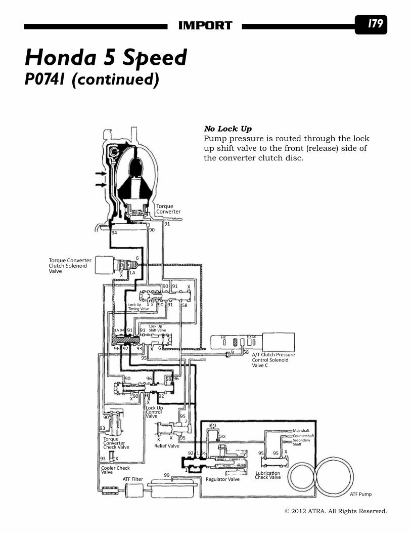
P0741 (continued)Honda 5 Speed
TorqueConverter
Torque ConverterClutch SolenoidValve
94 9091
6
LAX
90 91 X
5890 91Lock UpTiming Valve
X X
Lock UpShift ValveLA 94 91 91
X939296586 A/T Clutch Pressure
Control SolenoidValve C
95
6
9690 96 58
Lock UpControl Valve
XX
90 92
90
93
TorqueConverterCheck Valve
93 X
Relief ValveX X 95
952
HX HXAX
HXAX
AX
92 1 95
199
Regulator Valve
95 95 X
LubricationCheck Valve
ATF Pump
ATF Filter
Cooler CheckValve
MainshaftCountershaftSecondaryShaft
No Lock UpPump pressure is routed through the lock up shift valve to the front (release) side of the converter clutch disc.

180 IMPORT
© 2012 ATRA. All Rights Reserved.
P0741 (continued)Honda 5 Speed
Torque ConverterClutch SolenoidValve
94
TorqueConverter
9091
6
LAX
90 91 X
5890 91Lock UpTiming Valve
X
58 A/T Clutch PressureControl SolenoidValve C
HX HXAX
Lock UpShift ValveLA 94 91 91
X939296
95
6
9690 96 58
Lock UpControl Valve
XX
90 92
90
93
TorqueConverterCheck Valve
93 X
Cooler CheckValve
Relief ValveX X 95
952
HXAX
AX
92 1 95
199
Regulator Valve
95 95 X
LubricationCheck Valve
ATF Pump
ATF Filter
MainshaftCountershaftSecondaryShaft
Partial Lock UpThe PCM turns the TCC solenoid on and TCC shift valve moves into the shifted po-sition. The PCM commands the CPC C to modulate pressure to the lock up control valve. The reduced pressure on the release side of the lock up clutch allows partial lock up clutch apply.

181IMPORT
© 2012 ATRA. All Rights Reserved.
TorqueConverter
Torque ConverterClutch SolenoidValve
9490
91
6
LAX
90 91 X
5890 91Lock UpTiming Valve
X X
Lock UpShift ValveLA 94 91 91
X939296586 A/T Clutch Pressure
Control SolenoidValve C
95
6
9690 96 58
Lock UpControl Valve
XX
90 92
90
93
TorqueConverterCheck Valve
93 X
Relief ValveX X 95
952
HX HXAX
HXAX
AX
92 1 95
199
Regulator Valve
95 95 X
LubricationCheck Valve
ATF Pump
ATF Filter
Cooler CheckValve
MainshaftCountershaftSecondaryShaft
P0741 (continued)Honda 5 Speed
Full Lock UpAs speed increase the PCM turns on CPC C solenoid full on. The lock up control valve moves further to open up the exhaust port and the lock up clutch fully applies.

182 IMPORT
© 2012 ATRA. All Rights Reserved.
P0741 (continued)Honda 5 Speed
Always completely disassemble the valve bodies. Remove every valve from every bore of every Honda every time. Replace or repair any worn end plugs. Drill a .030”-.050” hole from line pressure to converter charge in the regulator valve body.
In rare occations such as the vehicle sitting for a prolong period of time, drain back may oc-cur. Which is possible with any transmission during this type of modification.
X
Drill a .030”-.050” hole from line pressure to converter charge in the regulator valve body. Location marked with an “X”.
X
183IMPORT
© 2012 ATRA. All Rights Reserved.
P0741 (continued)Honda 5 Speed
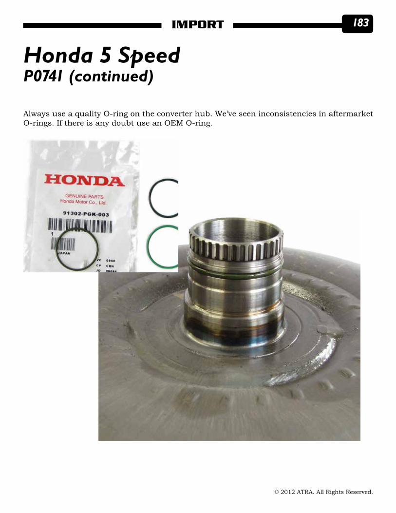
Always use a quality O-ring on the converter hub. We’ve seen inconsistencies in aftermarket O-rings. If there is any doubt use an OEM O-ring.

184 IMPORT
© 2012 ATRA. All Rights Reserved.
Always inspect the end plugs on the valve bodies. Replace or repair the end plugs as nec-essary. Some replace the end plugs with O-ringed plugs as part of the rebuild. Plugs that have notches can not be replaced with flat plugs. They must be replaced with a notch style plug.
P0741 (continued)Honda 5 Speed
Always inspect the pump assembly for wear. Check the side clearance and the axial clear-ance. A worn pump can cause low line pressure at idle.
Notch must face towards the spring

185IMPORT
© 2012 ATRA. All Rights Reserved.
P0741 (continued)Honda 5 Speed
Always inspect the torque converter check valve spring and bore. A collapsed spring or a cocked valve can cause low converter apply pressure.
Torque Converter Check ValveSpring measurements1.348” X .329” X .046”

186 IMPORT
© 2012 ATRA. All Rights Reserved.
P0741 (continued)Honda 5 Speed
The best way to keep these transmissions on the road is to add a stand alone cooler. A cooler that is rated at or near 22,000 GVW and 22,000 BTU capacity is best. The best way to install the cooler is to fabricate brackets so that the cooler will not vibrate against the AC condenser.

187IMPORT
© 2012 ATRA. All Rights Reserved.
Pressure Regulator SystemHonda
Many technicians may think that line pressure is responsible for shift concerns in Honda transmissions. This is not true! Clunky down shifts and rough up shifts are typically caused by the CPC valve issues and/or CPC solenoid issues.
The Honda PR valve regulates pressure to 125-130 psi at all times. Line pressure rise only occurs when the stator tube is twisted by the torque converter.

188 IMPORT
© 2012 ATRA. All Rights Reserved.
Ads.FH10 Thu Mar 10 11:56:48 2011 Page 1
Composite
C M Y CM MY CY CMY K
The turning torque of the stator support pushes on the end of the pressure regulator valve to cause line pressure rise on take off.
Pressure Regulator System (continued)Honda

189IMPORT
© 2012 ATRA. All Rights Reserved.
Ads.FH10 Thu Mar 10 11:56:48 2011 Page 1
Composite
C M Y CM MY CY CMY K

190 IMPORT
© 2012 ATRA. All Rights Reserved.
Pressure Regulator System (continued)Honda
1st Hold/4thAccumulator 1st Accumulator
154C
10
1st/1st Hold Clutch2nd Accumulator
1015 20 2ndClutch
3rd ClutchTransmission FluidPressureSwitch
3rd Clutch
3030
3rdAccumulator
4th Clutch4th ClutchTransmission FluidPressureSwitch
5th Clutch
40 50
5thAccumulator
50
5540
TorqueConverter
40 15 Shift Valve D
254A5JX5MX
5M5H Shift Valve B
9 5F 5D
SB
Kickdown Valve
4A
H9X
30
KickdownShort Valve CPC Valve A
CPC Valve B564
4
SB
X
X
X
ON
ON
ON6
Shift SolenoidValve B
Shift SolenoidValve C
Shift SolenoidValve A
9091
94TorqueConverterClutchSolenoidValve
6
LAXLock UpTiming Valve
ShiftValve A
X X 90 91 58
90 91 X
Shift Valve E
4C SA
X 55
4CCPCValve C
4 1
Shift Valve C5C
4B
6 4 4 H1X 4 5B H2X
X
50 4A SC
4B 57
6
6
A/T Clutch PressureControl SolenoidValve C
A/T Clutch PressureControl SolenoidValve A
A/T Clutch PressureControl SolenoidValve B
58
56
5
576
9191LA 94
93 X 69296
Lock UpShiftValve
96 965890
X90X 92
Lock UpControlValve 95
290
93
TorqueConverterCheck Valve
X93Cooler CheckValve
ATF Filter
Relief Valve
XX 95
99
92 1 95
AX AX
HX
Regulator Valve LubricationCheck Valve
Manual Valve
MainshaftCountershaftSecondaryShaft
1
10
4 25 2
3
3
33
ATF Pump
ReverseCPCValve
Servo Valve
ServoControlValve
43 4
X
4
3 9 4 X 10
Modulator Valve
3
95 95 X
51 50
X
1
HONDARaybestos introduces the new
GPX Friction Plate for Honda
transmissions. The “Global
Performance Extra,” made in
America, is superior to any
other friction plate for Honda.
The GPX Friction Plate shifting
performance matches Honda
perfectly with even greater
durability. Engineered to fit
right and outperform any
other Honda friction plate.
Features and Benefits
• Proprietary Raybestos engineered friction material and unique groove design provide smooth shifts and greater durability
• The industry’s tightest manufacturing specifications for trouble-free installation
• Withstands higher temperatures than the OE
• Made in the USA
• An OE replacement without the OE cost
711 Tech Drive, Crawfordsville, IN 47933 • Toll Free: 800-729-7763 • Fax: 765-364-4573 • Email: [email protected]
The CPC solenoids control the CPC valves, they DO NOT control line pressure rise. During a shift, line pressure is regulated by the CPC solenoids to control shift feel. Sticking CPC valves are the major cause of shift feel concerns in Honda transmissions today. Always remove every valve from every bore for cleaning and inspection. All valves must drop freely into their bores. Always use a torque wrench on all valve body bolts.

191IMPORT
© 2012 ATRA. All Rights Reserved.
HONDARaybestos introduces the new
GPX Friction Plate for Honda
transmissions. The “Global
Performance Extra,” made in
America, is superior to any
other friction plate for Honda.
The GPX Friction Plate shifting
performance matches Honda
perfectly with even greater
durability. Engineered to fit
right and outperform any
other Honda friction plate.
Features and Benefits
• Proprietary Raybestos engineered friction material and unique groove design provide smooth shifts and greater durability
• The industry’s tightest manufacturing specifications for trouble-free installation
• Withstands higher temperatures than the OE
• Made in the USA
• An OE replacement without the OE cost
711 Tech Drive, Crawfordsville, IN 47933 • Toll Free: 800-729-7763 • Fax: 765-364-4573 • Email: [email protected]

192 IMPORT
© 2012 ATRA. All Rights Reserved.
722.6Binds on the 3-4 Shift or Won’t Hold 4th Drops Back to 3rdA Dodge, Chrysler, Jeep, or Mercedes Benz vehicle equipped with a 722.6 transmission also known as the NAG1 arrives at your shop with a bind during the 3-4 shift.
This symptom may or may not set code P0734 gear ratio error in 4th on Dodge, Chrysler, or Jeep vehicles. Mercedes vehicles may set code P0700. When using Mercedes software, it may set code 051 (gear implausible), or 147 (transmission slips).
Diagnostic codes between 2 and 65 indicate hard codes: problems that are there now, while you’re retrieving the codes. Codes 96 and higher indicate soft codes: history codes that set previously, but aren’t there now. An error code 051 that isn’t present during code retrieval will have 96 added to it, to become code 147.
A bind on the 3-4 shift may be caused by a broken 3-4 Shift Pressure Valve Spring. We’ve seen several of these springs broken or collapsed. This is why just picking at the valve may not lead you to the cause of the complaint. For now, there are no aftermarket fixes. You’ll have to match another spring to these dimensions from a core or other source.
The spring dimension is: Free Length Outside Diameter Wire Diameter Coil Count0.955” 0.255” 0.023” 15
12345678 3-4 Overlap Regulating Valve, Sleeve, and Piston
722.6 Upper Valve Body Valve Identification
Manual Valve3-4 Holding Pressure Shift Valve
3-4 Command Valve3-4 Shift Pressure Valve
2-3 Overlapping Valve, Sleeve, and PistonLubricating Presssure Regulating ValveOperating Pressure Regulating Valve

193IMPORT
© 2012 ATRA. All Rights Reserved.
722.6Binds on the 3-4 Shift or Won’t Hold 4th Drops Back to 3rd (continued)
7
1
2 3
865
4A bind on the 3-4 shift may be caused by a broken 3-4 Shift Pressure Valve Spring

194 IMPORT
© 2012 ATRA. All Rights Reserved.
722.6Binds on the 3-4 Shift or Won’t Hold 4th Drops Back to 3rd (continued)
B1
1
K1 K2 B3 K3 B2
10PRND
11
14
1-2/4-5 Command
151-2/4-5 Holding
161-2/4-5 Shift Pres.
1-2/4-5 Overlap
1-2/4-5Solenoid
LP Sol in Pres.
TC
TC In
LinePressure
(50-350 psi)
ControlValve
Pressure(105-120 psi)
Shift ValvePressure
(50-55 psi)
ShiftPressure
(0-220 psi)
TC In(50-100 psi)
TC Out(10-45 psi)
ModulatingPressure
(0-120 psi)
Lube(5-40 psi)
ShiftPressure/Control
Solenoid Valve(0-120 psi)
Sump
Lube
CoolerTC Out
22
LU
LU Cont.
18
20
2/3 Sol
2-3 Command
25
2-3 Holding
24
2-3 Shift Pres.24
2-3 Overlap
2
SP VFS LP VFSLU SolPWM
Dam
per
21 Sol in P
TC Limit 3
Drive3rd
Sump
Pump
4LP Reg
9
19Shift P Reg
3-4 Sol3-4 Overlap 8
3-4 Shift Pres. 7
3-4 Holding 5
3-4 Command B2 Shift Valve
275
13
NAG 1 Hydraulics Shown

195IMPORT
© 2012 ATRA. All Rights Reserved.
722.6Binds on the 3-4 Shift or Won’t Hold 4th Drops Back to 3rd (continued)
B1
1
K1 K2 B3 K3 B2
10PRND
11
14
1-2/4-5 Command
151-2/4-5 Holding
161-2/4-5 Shift Pres.
1-2/4-5 Overlap
1-2/4-5Sol
LP Sol in Pres.
TC
TC In
LinePressure
(50-350 psi)
ControlValve
Pressure(105-120 psi)
Shift ValvePressure
(50-55 psi)
ShiftPressure
(0-220 psi)
TC In(50-100 psi)
TC Out(10-45 psi)
OverlapPressure
ModulatingPressure
(0-120 psi)
Lube(5-40 psi)
Sump
Lube
CoolerTC Out
22
LU
LU Cont.
18
20
2/3 Sol
2-3 Command
25
2-3 Holding
26
2-3 Shift Pres.
24
2-3 Overlap
2
SP VFS LP VFSLU SolPWM
Dam
per
21 Sol in P
TC Limit 3
DriveD3 to D4Transition
Sump
Pump
4LP Reg
9
19Shift P Reg
3-4 Sol3-4 Overlap 8
3-4 Shift Pres. 7
3-4 Holding 5
3-4 Command B2 Shift Valve
275
13
ShiftPressure/Control
Solenoid Valve(0-120 psi)
NAG 1 Hydraulics Shown

196 IMPORT
© 2012 ATRA. All Rights Reserved.
722.6Binds on the 3-4 Shift or Won’t Hold 4th Drops Back to 3rd (continued)
B1
1
K1 K2 B3 K3 B2
10PRND
11
14
1-2/4-5 Command
151-2/4-5 Holding
161-2/4-5 Shift Pres.
1-2/4-5 Overlap
1-2/4-5Sol
LP Sol in Pres.
TC
TC In
LinePressure
(50-350 psi)
ControlValve
Pressure(105-120 psi)
Shift ValvePressure
(50-55 psi)
ShiftPressure
(0-220 psi)
TC In(50-100 psi)
TC Out(10-45 psi)
ModulatingPressure
(0-120 psi)
Lube(5-40 psi)
ShiftPressure/Control
Solenoid Valve(0-120 psi)
Sump
Lube
CoolerTC Out
22
LU
LU Cont.
18
20
2/3 Sol
2-3 Command
25
2-3 Holding
26
2-3 Shift Pres.24
2-3 Overlap
2
SP VFS LP VFSLU SolPWM
Dam
per
21 Sol in P
TC Limit 3
Drive4th
Sump
Pump
4LP Reg
9
19Shift P Reg
3-4 Sol3-4 Overlap 8
3-4 Shift Pres. 7
3-4 Holding 5
3-4 Command B2 Shift Valve
275
13
NAG 1 Hydraulics Shown

197IMPORT
© 2012 ATRA. All Rights Reserved.
2-3 ChatterRE5R05A
A 2-3 chatter can be caused by many things let’s take a look at the circuit and the areas you need to pay close attention to.
A 2-3 can be caused by several components. Any or all of these components can be damaged.
1. Case2. Valve Body3. Center Support4. Center Sun Shaft5. Output Shaft6. High/Low Reverse Drum
The first thing we have to understand is how the chatter is caused. You either have a mis-matched combination between fluid and clutch material or you don’t have enough clamping force to apply the clutches.
More often then not, especially with this unit, the sealing rings become a serious issue. Not because of the way they’re manufactured, rather the amount of sealing rings necessary to apply the High/Low Reverse Clutch. There are (6) sealing rings needed to allow the clutch to operate, (2) seals on the Output Shaft and (4) seals on the Center Sun Shaft.

198 IMPORT
© 2012 ATRA. All Rights Reserved.
2-3 Chatter (continued)RE5R05A
CaseDuring the repairs, make sure the case is not damaged and you have a good solid fit of the Center Support into the case. Use the following illustration for air checking the High/Low Reverse Clutch. You can use between 10-20 psi to charge the system. There will be a sig-nificant air leak, but it will charge the piston.
We suggest removing the return spring assmebly from the piston and reinstalling the clutches for the TEST. This will allow you to test the system and verify the piston is sealing.
High/Low Reverse Drum air test port at the case.
High/Low Reverse Drum air test port at the center support

199IMPORT
© 2012 ATRA. All Rights Reserved.
2-3 Chatter (continued)RE5R05A
Fluid enters the center support though the case from the valve body. From there it is direct-ed though the center shaft into the output shaft and back up though the center shaft. From there the fluid is directed into the high/low reverse piston.
From the Case

200 IMPORT
© 2012 ATRA. All Rights Reserved.
2-3 Chatter (continued)
Center SupportOnce the fluid leaves the valve body it enters the Center Support. The Center Support is lo-cated at the bottom of the transmission and is bolted to the case with (3) allen bolts. Make sure the bolts are properly installed and torqued properly.
Fluid enters the Center Support and is directed thru the center support feed holes to the middle of the support.
From the Valve Body
To the Center Sun Shaft
RE5R05A

201IMPORT
© 2012 ATRA. All Rights Reserved.
2-3 Chatter (continued)
Center Sun ShaftAfter exiting the Center Support fluid enters between the lower two sealing rings. These rings only purpose is to take oil from the Center Support to the High/Low Reverse drum without having directional feed tubes. It has to use the output shaft as a fluid diverter.
RE5R05A

202 IMPORT
© 2012 ATRA. All Rights Reserved.
2-3 Chatter (continued)
Output Shaft
The two seals on the output shaft are very important. These seals are used to direct oil from the center support and sun gear shaft to the High/Low Reverse Drum. Also check the shaft ring lands for mis-machining or ring land damage.
RE5R05A
Poor ring groove caus-ing a 2-3 chatter.

203IMPORT
© 2012 ATRA. All Rights Reserved.
High/Low Reverse Drum
2-3 Chatter (continued)RE5R05A
The High/Low Reverse Drum assembly is very difficult to air test, there are multiple inlets for fluid to engage the piston. Having a good seal is essential to repairing the transmission.

204 IMPORT
© 2012 ATRA. All Rights Reserved.
2-3 Chatter (continued)
Valve Body 2nd Gear PositionIn the 2nd gear position the High/Low Reverse Clutch Valve is stroked against the spring by Pilot Valve (A) oil. Mainline oil is at the valve but is stopped by the valve land. Always check for valve wear, spring damage, plug or end cap leakage.
RE5R05A
Line PressSolenoid
(Pulsed N/V)
Cooler
TorqueConv CLSolenoid
(Pulsed N/V)
Direct CLSolenoid
(Pulsed N/A)
Front BrakeSolenoid
(Pulsed N/V)
Input CLSolenoid
(Pulsed N/A)
High & LowRev CL
Solenoid(Pulsed N/A)
Low CoastBrake
Solenoid(On/Off N/C
PressureTaps
High & LowReverse ClutchControl Valve x
OFF
ONONONOFFOFFON
PressureSW3 (I/C)
PressureSW5 (D/C)
PressureSW6 (H&LR/C)
TC OUT
TC IN
TCCL T/C Lube
ValveT/C CL
ControlValve
Direct CLControlValve
Input CLControlValve Press
Tap
DirectClutch
SwitchingValve
Input Clutch
ForwardBrake Clutch
Reverse Clutch
High & LowReverse Clutch
Direct Clutch(Small Cavity)
Low CoastBrake
Direct Clutch(Large Cavity)
RearLube Cancel(Balance Pistons)
Front BrakeBand
MANUAL VALVE
INOUT
Pump
Sump
CoolerBypassValve
PressureSW1 (FR/B)
Line PressRelief Valve
Oil Strainer
Lube
x
x
TCCRegulator
Valve
x
x
PressureRegulator
Valve
Front BrakeControl Valve
x
x
x
PilotValve
A
PilotValve
B
x x
x
Low CoastBrake
SwitchingValve
xx
PressureSW2
(LC/B)
N-D AccumulatorLow Coast BrakeReducing Valve
N-RACC
N-RACC
AccumulatorControlValve
A/T Fluid Temp SensorP R
N D
In Out
x
x
xx
x
x
x x x
RE5R05A (2002 - Mid 04) 2ndGear
205IMPORT
© 2012 ATRA. All Rights Reserved.
2-3 Chatter (continued)
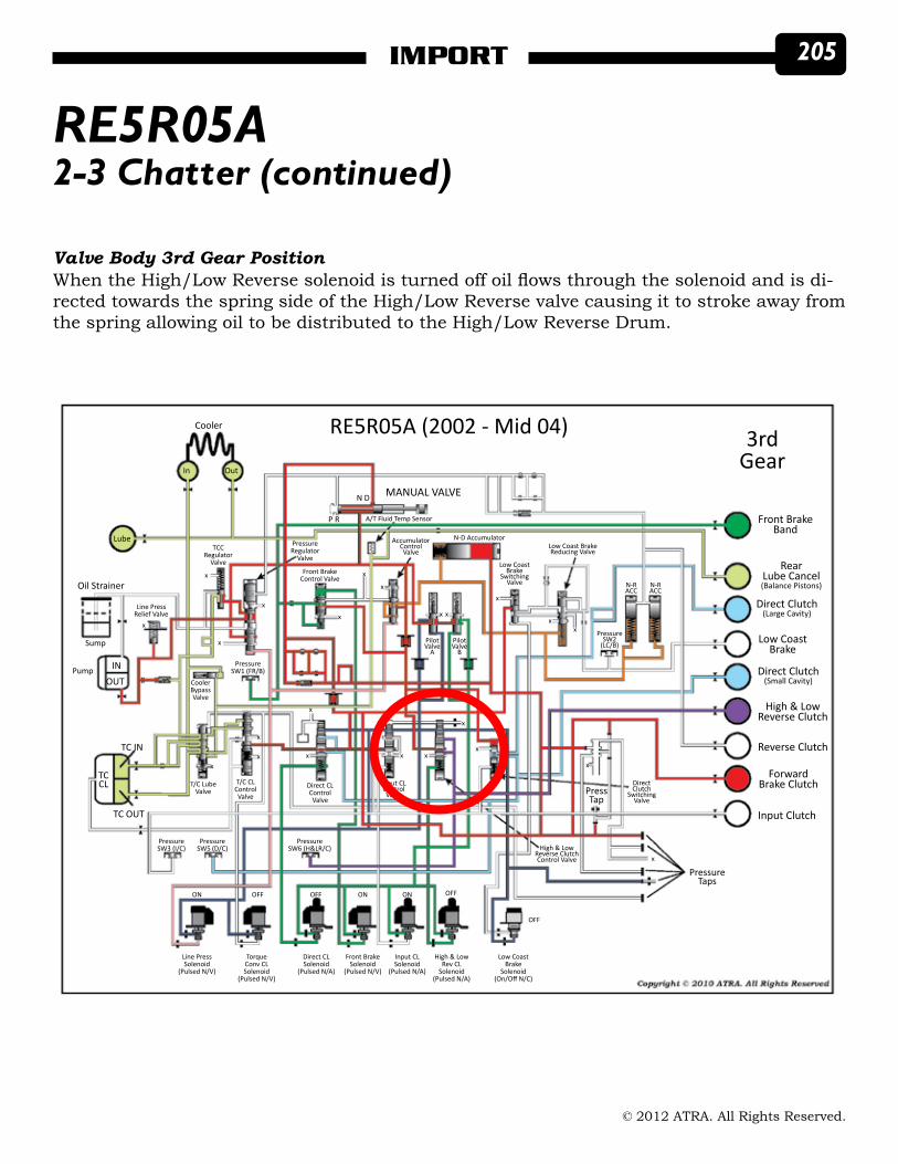
Valve Body 3rd Gear PositionWhen the High/Low Reverse solenoid is turned off oil flows through the solenoid and is di-rected towards the spring side of the High/Low Reverse valve causing it to stroke away from the spring allowing oil to be distributed to the High/Low Reverse Drum.
RE5R05A
Line PressSolenoid
(Pulsed N/V)
Cooler
TorqueConv CLSolenoid
(Pulsed N/V)
Direct CLSolenoid
(Pulsed N/A)
Front BrakeSolenoid
(Pulsed N/V)
Input CLSolenoid
(Pulsed N/A)
High & LowRev CL
Solenoid(Pulsed N/A)
Low CoastBrake
Solenoid(On/Off N/C)
PressureTaps
High & LowReverse ClutchControl Valve x
OFF
OFFONONOFFOFFON
PressureSW3 (I/C)
PressureSW5 (D/C)
PressureSW6 (H&LR/C)
TC OUT
TC IN
TCCL T/C Lube
ValveT/C CL
ControlValve
Direct CLControlValve
Input CLControlValve Press
Tap
DirectClutch
SwitchingValve
Input Clutch
ForwardBrake Clutch
Reverse Clutch
High & LowReverse Clutch
Direct Clutch(Small Cavity)
Low CoastBrake
Direct Clutch(Large Cavity)
RearLube Cancel(Balance Pistons)
Front BrakeBand
MANUAL VALVE
INOUT
Pump
Sump
CoolerBypassValve
PressureSW1 (FR/B)
Line PressRelief Valve
Oil Strainer
Lube
x
x
TCCRegulator
Valve
x
x
PressureRegulator
Valve
Front BrakeControl Valve
x
x
x
PilotValve
A
PilotValve
B
x x
x
Low CoastBrake
SwitchingValve
xx
PressureSW2
(LC/B)
N-D AccumulatorLow Coast BrakeReducing Valve
N-RACC
N-RACC
AccumulatorControlValve
A/T Fluid Temp SensorP R
N D
In Out
x
x
xx
x
x
x x x
RE5R05A (2002 - Mid 04) 3rdGear
x

206 IMPORT
© 2012 ATRA. All Rights Reserved.
RE5R05ANo Upshift, Burnt Direct Clutches
No upshift and burnt direct clutches may be caused by the inner sleeve of the Direct Drum rotating and blocking off the apply ports. This can also be found from brand new parts pur-chased.
Closely inspect the sleeve, make sure the apply holes line up before assembly.
207IMPORT
© 2012 ATRA. All Rights Reserved.
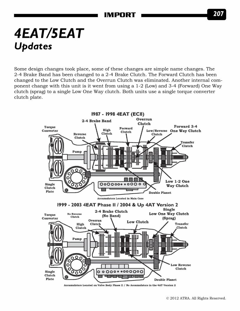
Some design changes took place, some of these changes are simple name changes. The 2-4 Brake Band has been changed to a 2-4 Brake Clutch. The Forward Clutch has been changed to the Low Clutch and the Overrun Clutch was eliminated. Another internal com-ponent change with this unit is it went from using a 1-2 (Low) and 3-4 (Forward) One Way clutch (sprag) to a single Low One Way clutch. Both units use a single torque converter clutch plate.
4EAT/5EATUpdates

208 IMPORT
© 2012 ATRA. All Rights Reserved.
There are several changes to the internal components with the elimination of the Low One Way Clutch. Although very similar to the Infiniti and Nissan RE5R05A 5 speed rear wheel drive transmission, with a Front Brake Band. Instead the Subaru uses a Front Brake Clutch integral to the pump assembly. Another major change is in the torque converter, it went from a single clutch plate to a multiple clutch assembly.
4EAT/5EATUpdates (continued)
209IMPORT
© 2012 ATRA. All Rights Reserved.
4EAT/5EAT
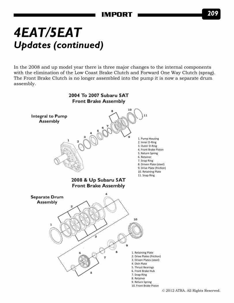
1. Pump Housing2. Inner D-Ring3. Outer D-Ring4. Front Brake Piston5. Return Spring6. Retainer7. Snap Ring8. Driven Plate (steel)9. Drive Plate (friction)10. Retaining Plate11. Snap Ring
1. Retaining Plate2. Drive Plates (friction)3. Driven Plates (steel)4. Dish Plate5. Thrust Bearings6. Front Brake Hub7. Snap Ring8. Retainer9. Return Spring10. Front Brake Piston
In the 2008 and up model year there is three major changes to the internal components with the elimination of the Low Coast Brake Clutch and Forward One Way Clutch (sprag). The Front Brake Clutch is no longer assembled into the pump it is now a separate drum assembly.
Updates (continued)

210 IMPORT
© 2012 ATRA. All Rights Reserved.
4EAT/5EAT
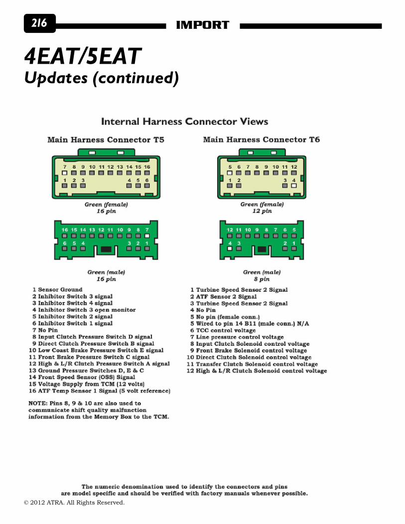
Solenoid location and descriptions also changed.
Updates (continued)

211IMPORT
© 2012 ATRA. All Rights Reserved.
4EAT/5EATUpdates (continued)

212 IMPORT
© 2012 ATRA. All Rights Reserved.
The memory box is located on the lower side of the valve body attached to a bracket as part of the internal wire harness. According to the information found in factory manuals this memory box stores hydraulic correction and learned values for the initial shifting pressures for each solenoid (basic settings).
The transmission is test driven with hydraulic control valves (solenoids) and the input and output torque variation characteristics that the transmission undergoes during shifting. This data is stored in the memory box as initial learning values at the factory.
The current oil pressure characteristics of the linear solenoids are measured by the trans-mission control module. The stored memory box data is used by the transmission control module to initially control the solenoids until adjustments are made to fine tune shift con-trol (shift learning control).
The memory box is often mistaken for the transmission control module (TCM). The TCM is located outside the transmission. Most common location is by the steering column depen-dent upon model and year.
The 2002 to mid 2004 Infiniti RE5R05A transmission uses a similar system, the memory box in these models is referred to as the “Shift Control Unit”.
4EAT/5EATUpdates (continued)

213IMPORT
© 2012 ATRA. All Rights Reserved.
4EAT/5EATUpdates (continued)

214 IMPORT
© 2012 ATRA. All Rights Reserved.
4EAT/5EATUpdates (continued)

215IMPORT
© 2012 ATRA. All Rights Reserved.
4EAT/5EATUpdates (continued)
216 IMPORT
© 2012 ATRA. All Rights Reserved.
4EAT/5EATUpdates (continued)

217IMPORT
© 2012 ATRA. All Rights Reserved.
4EAT/5EATUpdates (continued)

218 IMPORT
© 2012 ATRA. All Rights Reserved.
RE5F22AStuck in Failsafe
Nissan Maxima equipped with a 3.5L engine and a RE5F22A no communication with the TCM during startup transmission is in failsafe and a Mode 4 is under the “F-Safe Mode”. Mode 4 in simple terms is “Failsafe”. Mode 4 can occur without a code! Mode 4 can not be cleared unless there is no fault.
This may be caused by a faulty A/T IGN relay, located in the right kick panel. The Nissan parts department may require the part number off the old relay, to get you the right relay.
Wiring issues can give you headaches…typically, it’s something simple.
Nissan wiring is nerve racking to test, small, fragile and hard to test.
PNP failures, causes failsafe. No codes, unable to clear codes, unable to clear Mode 4. Check the PNP data on the scan tool, wiggle the wires and move the shifter handle. If the data, fluctuates or the dash lights fluctuate during this test replace the PNP.

219IMPORT
© 2012 ATRA. All Rights Reserved.
Mode 1 = Readiness Tests; Access to emission-related data (inputs-outputs)Mode 2 = Freeze Data; any data stored in the 1st Trip Freeze FrameMode 3 = DTC’s; Stored DTC’s with-in the ECMMode 4 = Clear Diag Info; Allows all codes to be cleared for all modesMode 6 = On Board Tests; Accesses the results of on board diagnosticsMode 7 = On Board Tests; Accesses the results of off board test drive to obtain results of emission related componentsMode 8 = EVAP system controlMode 9 = Calibration ID; Enables Off board Test device to request VIN and other info.
RE5F22AStuck in Failsafe (continued)
With-in the scan parameters there is a “F-Safe Mode”, this mode is telling you what mode the failsafe is.
All of these modes can be set with or without codes associated to them.

220 IMPORT
© 2012 ATRA. All Rights Reserved.
RE5F22AStuck in Failsafe (continued)
The powertrain and transmission control modules are located under the right hand side of the dash. The transmission control relay is also located in this area.

221IMPORT
© 2012 ATRA. All Rights Reserved.
RE5F22AStuck in Failsafe (continued)
Mode 4 tells us the TCM and/or the PNP have an issue. It does not tell us what the issue is, or when the issue is happening, nor does it code up. If the vehicle comes in for a no code failsafe, simply replace the PNP. To clear the Mode 4, you must have the PNP in the neutral position and your foot on the brake.

222 IMPORT
© 2012 ATRA. All Rights Reserved.
RE5F22AStuck in Failsafe (continued)
The transmission control relay is the main culprit regarding this failure. The reason for this is simply the way the relay is manufactured. Over time the contact arm weakens and causes the relay to intermittently fail. When this happens the transmission control module never completed its closed loop circuit.
Milwaukee
NashvilleLos Angeles
Toronto
BridgeportPortland
Salt Lake City
Detroit
Vancouver
ATRA.com has become the most visited
Web site in the transmission industry.
Thousands of new customers have been using ATRA’s
Web site to find transmission repair shops in their area.
It can be. Being an ATRA member means ATRA will place a link to your Web site on ATRA.com, where customers can use the local search feature to find shops in their area. This tool is beginning to appear in top search results for transmission repair on Google. This means people looking for shops in search engines are being directed to ATRA’s Web site and ATRA members.
The page views have doubled since the launch of ATRA’s local search feature. That’s potential business you cannot even begin to gain strictly from word-of-mouth referrals.
Your Web site is an essential tool to get transmissions in need of repair into your shop. Now it can be even more powerful. Join ATRA today and start reaping the benefits of ATRA’s Web presence.
Visit members.ATRA.com or call 805-604-2000
AUTOMATIC TRANSMISSIONREBUILDERS ASSOCIATION
Cleveland
ATRA.comATRA.com
Vancouver
DrivingCUstomersDrivingCUstomersDrivingCUstomersto yoUDrivingCUstomersto yoU is your shop one of them?

223IMPORT
© 2012 ATRA. All Rights Reserved.
Milwaukee
NashvilleLos Angeles
Toronto
BridgeportPortland
Salt Lake City
Detroit
Vancouver
ATRA.com has become the most visited
Web site in the transmission industry.
Thousands of new customers have been using ATRA’s
Web site to find transmission repair shops in their area.
It can be. Being an ATRA member means ATRA will place a link to your Web site on ATRA.com, where customers can use the local search feature to find shops in their area. This tool is beginning to appear in top search results for transmission repair on Google. This means people looking for shops in search engines are being directed to ATRA’s Web site and ATRA members.
The page views have doubled since the launch of ATRA’s local search feature. That’s potential business you cannot even begin to gain strictly from word-of-mouth referrals.
Your Web site is an essential tool to get transmissions in need of repair into your shop. Now it can be even more powerful. Join ATRA today and start reaping the benefits of ATRA’s Web presence.
Visit members.ATRA.com or call 805-604-2000
AUTOMATIC TRANSMISSIONREBUILDERS ASSOCIATION
Cleveland
ATRA.comATRA.com
Vancouver
DrivingCUstomersDrivingCUstomersDrivingCUstomersto yoUDrivingCUstomersto yoU is your shop one of them?

224 IMPORT
© 2012 ATRA. All Rights Reserved.
Seal Aftermarket Products LLC2315 S.W. 32 Ave., Pembroke Park, FL 33023
Phone 954-364-2400 • Toll Free 800-582-2760 • Fax 954-364-2401www.sealaftermarketproducts.com
TM
Experts in the automatic transmission aftermarket, we at Seal Aftermarket ProductsTM
(SAP) are committed to developing and producing the “Best Sealing Kits in the Industry”. We partner with OEM
suppliers such as Parker Hannifin®, Dupont® & Federal Mogul® to develop premium compounds in order to provide
solutions to “problems”, resulting in improved performance and reliability. Toledo Trans-KitTM Automatic Transmission Kits are
designed with the Rebuilder in mind, with more OE (or better) content and extras you won’t find elsewhere. Toledo
Trans-KitTM & BrycoTM brands have been distributed throughout the world for more than thirty (30) years. Our automatic
transmission kits and components cover most American, Asian, and European automatic transmissions. We ship
anywhere in the world. Every kit is tested by experienced Rebuilders to ensure
component content and proper fit prior to the being released for sale. Our Commitment is to listen to feedback from the rebuilder, implement suggestions and offer engineered solutions.
OE quality - aftermarket extras - packaged with the Rebuilder in mind
- global application solutions…….. Seal Aftermarket ProductsTM
is your source forengineered solutions!
SEAL AFT.indd 2 10/2/11 1:34 AM