proyectos: dpi2010-15123 ccg10-uc3m/dpi-4694. · vulnerability studies of cfrp aerospace structures...
TRANSCRIPT
This is a postprint version of the following published document:
Artero-Guerrero, J. A.; Pernas-Sánchez, J.; López-Puente, J.; Varas, D. (2014). "On the influence of filling level in CFRP aircraft fuel tank subjected to high velocity impacts, Composite Structures". Composite Structures, v. 107, January, pp. 570-577.DOI: 10.1016/j.compstruct.2013.08.036
© Elsevier
This work is licensed under a Creative Commons Attribution-NonCommercial-NoDerivatives 4.0 International License.
Proyectos:
DPI2010-15123CCG10-UC3M/DPI-4694.
On the influence of filling level in CFRP
aircraft fuel tank subjected to high velocity
impacts
J.A. Artero-Guerrero, J. Pernas-Sanchez, J. Lopez-Puente,
D.Varas ∗
Department of Continuum Mechanics and Structural Analysis. University Carlos
III of Madrid. Avda. de la Universidad, 30. 28911 Leganes, Madrid, Spain
Key words: Carbon fiber; Hydrodynamic RAM; fluid-structure interaction;
partially fluid-filled tank; impact; numerical simulation.
Abstract
In this work, the process of impact that takes place in a partially filled tank is
analyzed, performing a numerical simulation, in order to understand the response of
the composite laminated structure. The commercial finite-element code LS-DYNA
v.R7 has been used to simulate an Hydrodynamic RAM event created by a steel
spherical projectile impacting a partially water-filled woven CFRP square tube using
two different approaches (MM-ALE and SPH). The intralaminar and interlaminar
damage have been taken into account implementing an user subroutine and by
∗ Corresponding author. Fax number: 34 916248331. E-mail address:
1
means of a cohesive interaction, respectively. Once the numerical model is validated
using available experimental data, the effect of the filling level in the failure of
the tank is analyzed in detail taking advantage of the information provided by the
numerical model.
1 Introduction
The importance of laminated composites structures is increasing everyday in the
aeronautical and aerospace industries. The special characteristics of this kind of ma-
terials (high strength-to-weight and stiffness-to-weight ratios as well as an anisotropic
behavior) make them specially useful to optimize designs fulfilling the requirements
of those mentioned industries, reducing weight and hence saving fuel consump-
tion. The carbon fiber reinforced plastics (CFRP), commonly manufactured with
an epoxy matrix, are one of the most used composite materials for structural ap-
plications, such as the fuselage and wings. The successful usage of these materials
in primary structures depends on the understanding of their response to a range of
potential impact loadings and resulting damage mechanisms.
Vulnerability studies of CFRP aerospace structures are becoming an issue of great
importance in the design of any aircraft [1]. These structures may suffer different
types of high velocity impact loads. Bird strikes [2] or hailstones [3] are specially
dangerous because of their high possibility of occurrence and their disastrous conse-
quences. The ice released from the edge of a propeller blade may impact the nacelle
of the twin engine or the fuselage [4], and runway debris may impact the underside
of the wing structures [5] causing hydrodynamic ram (HRAM) effects in the fuel
tanks.
2
The HRAM phenomenon, which is considered one of the most important factors
in aircraft vulnerability, appears when a high-energy object penetrates a fluid-filled
tank and transfers its kinetic energy through the fluid to the surrounding struc-
ture. This effect increases the risk of catastrophic failure and excessive structural
damage. HRAM is particularly dangerous for aircrafts with lightweight designs, and
hence with composite wing fuel tanks, because the structural resistance of their in-
tegral fuel tanks cannot be improved by strengthening the airframe since it would
counteract the requirements of a lightweight design. Vulnerability to HRAM has
been usually related to military aircraft, but commercial airplanes are not exempt
of its effect. Maybe the most well-known example of the importance of the HRAM
phenomenon is the Concorde accident that occurred in 2000. The final investigation
report revealed that the HRAM had played a significant role in the aircraft failure.
Usually, the HRAM phenomenon is analyzed considering completely filled tanks;
but in real flight situation, it is more likely that an impact may occur when the
tank is partially filled. The influence of the filling percentage on the failure of the
tanks has been clearly shown in experimental tests [6]. The HRAM effects in a
partially filled tank can not be neglected with respect to the effects observed in a
completely filled one. Indeed the failure induced in a partially filled tank can be so
dangerous as in a completely filled one.
The process of impact that takes place in a partially filled tank should be carefully
analyzed in order to understand the response of the composite laminated structure.
To achieve this, an impact of an steel sphere into a partially water-filled CFRP
woven laminate tank, reproducing an HRAM event, is simulated in this work. The
intralaminar damage of the CFRP has been taken into account implementing an
user subroutine. The interlaminar damage is reproduced using a cohesive interac-
tion. Two different approaches (MM-ALE and SPH) have been used in order to
demonstrate if both methods can accurately reproduce such a complex phenom-
3
enon in a partially filled tank. Once the numerical model is validated by means of
the available experimental data, the effect of the filling level in the failure of the
tank can be analyzed in detail taking advantage of the information provided by the
numerical model.
2 Definition of the problem
The problem configuration detailed in a previous work of D. Varas et al. [6] has been
chosen in order to take advantage of the experimental results obtained and hence
being able to validate the numerical model. The tests consisted on high velocity
impacts of steel spheres into a CFRP woven tank filled at different water levels.
The impacted tanks consisted on square woven CFRP tubes 150 mm wide, 2.2 mm
thick and 750 mm long. The composite woven laminated selected was the AGP-
193-PW manufactured by Hexcel Composite, composed by 10 plies ([0]10). Each
ply was made with a plain weave of AS4 carbon fibers and the 8552 epoxy resin.
The tube was closed with two PMMA windows 30 mm thick, fixed with four steel
bars, which allow the recording of the whole impact and penetration process by
means of a Photron Ultima APX-RS digital high-speed camera. An Arrisun 12 Plus
lamphead with a 1200W Hydrargyrum Medium Arc Iodide (HMI) lamp was used to
assure an appropriate lighting and obtain optimal images of the penetration process.
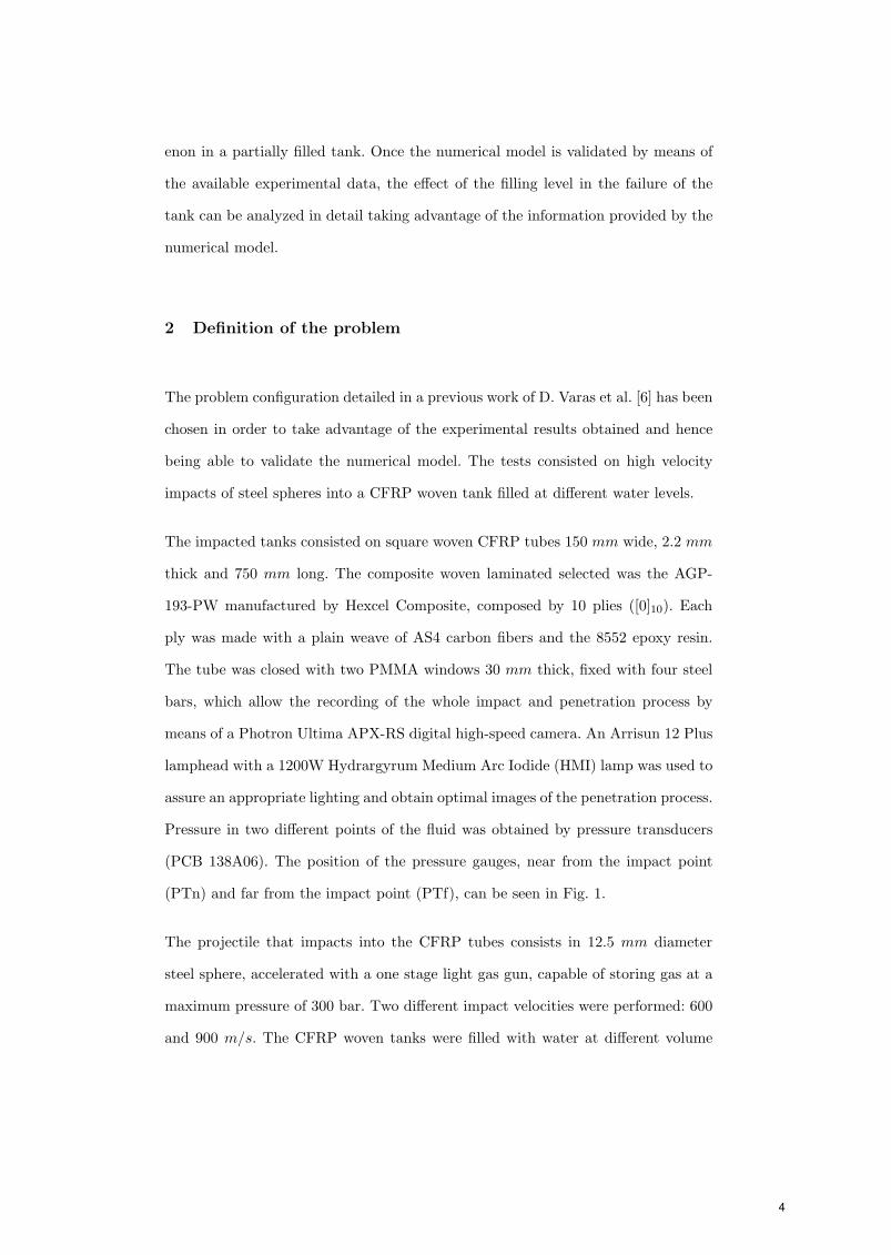
Pressure in two different points of the fluid was obtained by pressure transducers
(PCB 138A06). The position of the pressure gauges, near from the impact point
(PTn) and far from the impact point (PTf), can be seen in Fig. 1.
The projectile that impacts into the CFRP tubes consists in 12.5 mm diameter
steel sphere, accelerated with a one stage light gas gun, capable of storing gas at a
maximum pressure of 300 bar. Two different impact velocities were performed: 600
and 900 m/s. The CFRP woven tanks were filled with water at different volume
4
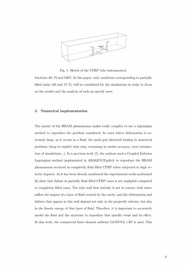
Fig. 1. Sketch of the CFRP tube instrumented.
fractions: 60, 75 and 100%. In this paper, only conditions corresponding to partially
filled tanks (60 and 75 %) will be considered for the simulations in order to focus
on the results and the analysis of such an special cases.
3 Numerical implementation
The nature of the HRAM phenomenon makes really complex to use a lagrangian
method to reproduce the problem considered. In cases where deformation is ex-
tremely large, as it occurs in a fluid, the mesh gets distorted leading to numerical
problems (drop in explicit time step, worsening in results accuracy, error termina-
tion of simulations...). In a previous work [7], the authors used a Coupled Eulerian
Lagrangian method implemented in ABAQUS/Explicit to reproduce the HRAM
phenomenon occurred in completely fluid filled CFRP tubes subjected to high ve-
locity impacts. As it has been already mentioned the experimental works performed
[6] show that failure in partially fluid filled CFRP cases is not negligible compared
to completely filled cases. The tube wall that initially is not in contact with water
suffers the impact of a layer of fluid created by the cavity, and the deformation and
failures that appear in this wall depend not only in the projectile velocity, but also
in the kinetic energy of that layer of fluid. Therefore, it is important to accurately
model the fluid and the structure to reproduce that specific event and its effect.
In this work, the commercial finite element software LS-DYNA v.R7 is used. This
5
software provides several techniques to solve fluid-structure interaction; particularly
two approaches have been used to model the fluid behavior: multimaterial Arbitrary
Lagrangian Eulerian (MM-ALE) and the Smooth Particle Hydrodynamics (SPH).
The lagrangian technique has been used to discretise the surrounding structure and
the projectile.
3.1 MM-ALE fluid model
The MM-ALE technique allows the motion of the mesh independently on the fluid
flow, avoiding mesh distortion problems. The multimaterial approach permits to
define more than one material inside each element. Fig. 2 shows both the whole
domain of the ALE model and the fluids considered to reproduce a partially filled
case. The problem under consideration can be simplified attending its symmetry,
hence only half of the problem has to be modeled obtaining a desirable reduction
of the computational cost. The domain dimensions have been defined to assure
that the deformed CFRP tube walls never reach the boundary of the MM-ALE
domain. Therefore, the interaction between fluid and the surrounding structure is
computed during the whole simulation, being able of reproducing the effect of the
HRAM phenomenon. The whole MM-ALE mesh is discretised by means of 8 node
solids elements, multimaterial, with reduced integration and hourglass control. In
order to assure an accurate contact between fluid and the surface of the woven
CFRP tube walls, both parts were discretized with the same element size. This fact
avoids possible leakage problems [8]. The element size of the fluid mesh was chosen
according to previous studies regarding deceleration of an sphere inside a fluid; a
value of 2 mm has been selected. Finally, 708.806 MM-ALE elements have been
used in the model.
6
(a) MM-ALE domain (b) MM-ALE fluids
Fig. 2. MM-ALE model done in LS-DYNA v.R7.
The fluid material behavior is defined by the following viscous constitutive equation:
σ = 2ηε′ − P I (1)
where η is the dynamic viscosity, ε′ is the deviatoric strain rate tensor, P is the
pressure and I, the identity tensor. The pressure P is related with density ρ using
a Mie-Gruneisen equation of state, where:
P =ρ0µD2
[1 +
(1 − γ0
2
)µ − a
2µ2]
[1 − (S1 − 1)µ − S2
µ2
µ+1 − S3µ3
(µ+1)2
]2 + (γ0 + aµ)E (2)
for compressed materials and P = 0 for expanded materials, avoiding negative
pressure in the fluid. In equation 2, the pressure P is calculated as a function of
the compression µ = ρ/ρ0 − 1, where ρ and ρ0 are the current and the initial
density respectively, and of the internal energy per unit volume E. S1, S2 and S3
are coefficients of the slope of the us − up curve where us is the shock velocity and
up is the particle velocity. D is the intercept of the us−up curve, which corresponds
to the adiabatic sound speed of water. γ0 is a material constant called Gruneisen
gamma and a is the first volume correction to γ0. Water properties (table 1) are
obtained from [9].
The air was modelled using the same constitutive equation 1, but in this case a
7
Linear Polynomial Equation of State is used. Pressure now is defined as:
P = C0 + C1µ + C2µ2 + C3µ
3 +(C4 + C5µ + C6µ
2)E (3)
The air is considered as an ideal gas by setting C0 = C1 = C2 = C3 = C6 = 0 and
C4 = C5 = γ − 1 where γ = Cp
Cv= 1.4 is the ratio between the specific heats. The
properties used for air are defined in table 1.
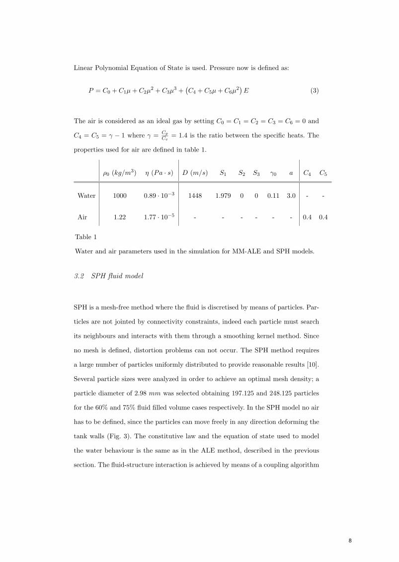
ρ0 (kg/m3) η (Pa · s) D (m/s) S1 S2 S3 γ0 a C4 C5
Water 1000 0.89 · 10−3 1448 1.979 0 0 0.11 3.0 - -
Air 1.22 1.77 · 10−5 - - - - - - 0.4 0.4
Table 1
Water and air parameters used in the simulation for MM-ALE and SPH models.
3.2 SPH fluid model
SPH is a mesh-free method where the fluid is discretised by means of particles. Par-
ticles are not jointed by connectivity constraints, indeed each particle must search
its neighbours and interacts with them through a smoothing kernel method. Since
no mesh is defined, distortion problems can not occur. The SPH method requires
a large number of particles uniformly distributed to provide reasonable results [10].
Several particle sizes were analyzed in order to achieve an optimal mesh density; a
particle diameter of 2.98 mm was selected obtaining 197.125 and 248.125 particles
for the 60% and 75% fluid filled volume cases respectively. In the SPH model no air
has to be defined, since the particles can move freely in any direction deforming the
tank walls (Fig. 3). The constitutive law and the equation of state used to model
the water behaviour is the same as in the ALE method, described in the previous
section. The fluid-structure interaction is achieved by means of a coupling algorithm
8
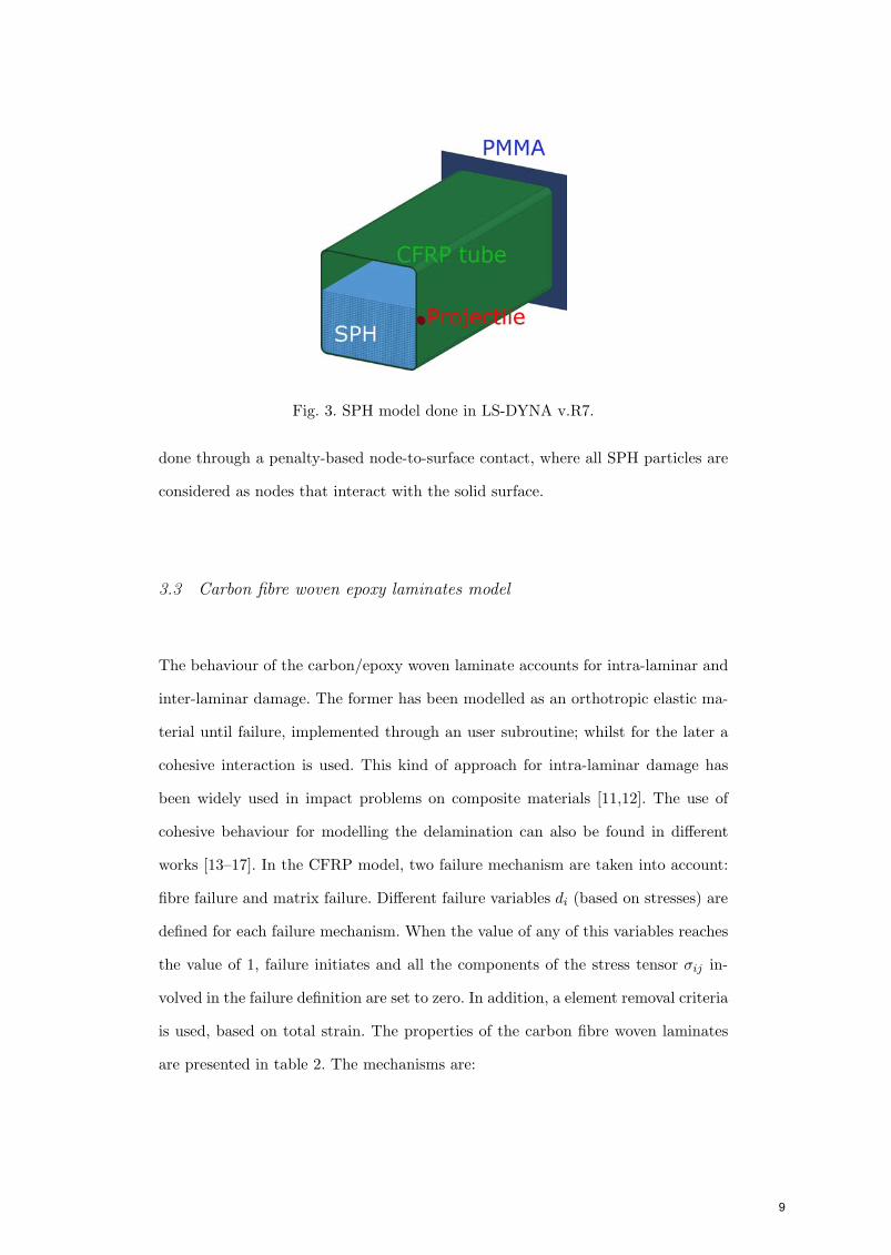
Fig. 3. SPH model done in LS-DYNA v.R7.
done through a penalty-based node-to-surface contact, where all SPH particles are
considered as nodes that interact with the solid surface.
3.3 Carbon fibre woven epoxy laminates model
The behaviour of the carbon/epoxy woven laminate accounts for intra-laminar and
inter-laminar damage. The former has been modelled as an orthotropic elastic ma-
terial until failure, implemented through an user subroutine; whilst for the later a
cohesive interaction is used. This kind of approach for intra-laminar damage has
been widely used in impact problems on composite materials [11,12]. The use of
cohesive behaviour for modelling the delamination can also be found in different
works [13–17]. In the CFRP model, two failure mechanism are taken into account:
fibre failure and matrix failure. Different failure variables di (based on stresses) are
defined for each failure mechanism. When the value of any of this variables reaches
the value of 1, failure initiates and all the components of the stress tensor σij in-
volved in the failure definition are set to zero. In addition, a element removal criteria
is used, based on total strain. The properties of the carbon fibre woven laminates
are presented in table 2. The mechanisms are:
9
• Fibre failure. Due to woven configuration, fibre failure can appear in the two in-
plane axes. The fibre failure criteria are described by means of df1 and df2, one
for each fibre direction:
df1 =
⎧⎪⎪⎪⎪⎪⎪⎨⎪⎪⎪⎪⎪⎪⎩
σ11
Xtif σ11 > 0
|σ11|Xc
if σ11 < 0
(4)
df2 =
⎧⎪⎪⎪⎪⎪⎪⎨⎪⎪⎪⎪⎪⎪⎩
σ22
Ytif σ22 > 0
|σ22|Yc
if σ22 < 0
(5)
where Xt and Xc are the strengths of the composite laminate in tension and
compression for the warp direction, and finally Yt and Yc are the strengths in
tension and compression for the fill direction.
• Matrix failure. The matrix failure distinguished two mechanisms: in-plane shear
(dm12) and out-plane crushing (dm3).
dm12 =σ12
S12(6)
dm3 =14
(σ33
Zc
)2
+Zc · σ33
4S13S23+
∣∣∣∣σ33
Zc
∣∣∣∣ + max
[(σ13
S13
)2
,
(σ23
S23
)2]
(7)
where S12, S13 and S23 are the shear strengths in the three different planes and
Zc is the strength in the through-thickness direction under compression. The
equation 7 applies only when σ33 < 0.
Inter-laminar damage is modelled through a cohesive surface interaction. The cohe-
sive behavior is based on a traction-separation law, in which is necessary to define
a damage initiation criteria and a damage evolution law. In this work, the damage
initiation is defined by eq. 8, where δ0 is the displacement at which softening starts,
10
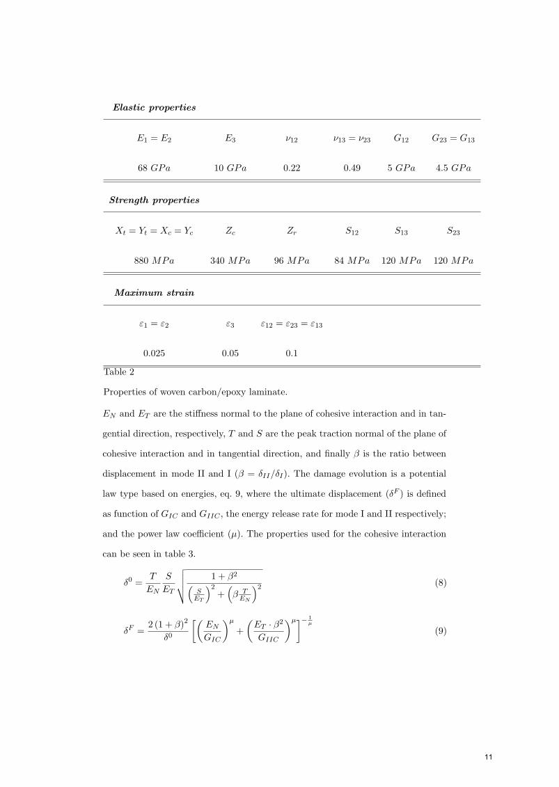
Elastic properties
E1 = E2 E3 ν12 ν13 = ν23 G12 G23 = G13
68 GPa 10 GPa 0.22 0.49 5 GPa 4.5 GPa
Strength properties
Xt = Yt = Xc = Yc Zc Zr S12 S13 S23
880 MPa 340 MPa 96 MPa 84 MPa 120 MPa 120 MPa
Maximum strain
ε1 = ε2 ε3 ε12 = ε23 = ε13
0.025 0.05 0.1
Table 2
Properties of woven carbon/epoxy laminate.
EN and ET are the stiffness normal to the plane of cohesive interaction and in tan-
gential direction, respectively, T and S are the peak traction normal of the plane of
cohesive interaction and in tangential direction, and finally β is the ratio between
displacement in mode II and I (β = δII/δI). The damage evolution is a potential
law type based on energies, eq. 9, where the ultimate displacement (δF ) is defined
as function of GIC and GIIC , the energy release rate for mode I and II respectively;
and the power law coefficient (µ). The properties used for the cohesive interaction
can be seen in table 3.
δ0 =T
EN
S
ET
√√√√ 1 + β2(S
ET
)2+
(β T
EN
)2 (8)
δF =2 (1 + β)2
δ0
[(EN
GIC
)µ
+(
ET · β2
GIIC
)µ]− 1µ
(9)
11
EN ET T S GIC GIIC µ
40 GPa 30 GPa 11 MPa 45 MPa 287 J/m2 1830 J/m2 1.42
Table 3
Parameters for the cohesive interface.
3.4 Box and projectile lagrangian FE model
The woven CFRP tube is discretised by means of eight node linear solid elements
with reduced integration and hourglass control. The mesh is more refined in the
impacted zone (1 × 1 mm2) than far from the impact point (until 7.3 × 4.5 mm2),
obtaining a mesh that accurately reproduces the damage induced according to pre-
vious works [18]. The CFRP tube walls present 10 elements through thickness, so
each element corresponds to one ply. The projectile is discretised by means of eight
node conventional solid elements with reduced integration and modelled as an elas-
tic material (ρ = 7850 Kg/m3; E = 210 GPa; ν = 0.3). The PMMA window is
discretised by means of four node conventional shell elements with reduced integra-
tion and modelled as an elastic material (ρ = 1180 Kg/m3; E = 3 GPa; ν = 0.35).
Both, steel and PMMA, are modeled as elastic materials since no plastic deforma-
tion nor damage is observed in none of them in the experimental tests.
4 Results
Numerical simulations were carried out at different impact velocities (600 m/s and
900 m/s) and different fluid filling levels (60 % and 75 %). The results obtained are
compared with the experimental data available [6] in order to validate the numerical
model. Additionally, MM-ALE method and SPH are compared analyzing their ad-
vantages and disadvantages to reproduce the effects of the HRAM phenomenon in
partially fluid filled CFRP tubes. Moreover, the kinematics of the layer of fluid that
12
initially is above the projectile trajectory will be studied in detail. This fluid layer
is raised by the projectile impacting the upper wall of the CFRP tank. A complete
analysis of this fluid-structure interaction is done in the section 4.2.
4.1 Validation
The numerical results are compared qualitative and quantitatively to the experi-
mental data.
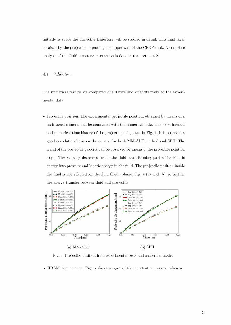
• Projectile position. The experimental projectile position, obtained by means of a
high-speed camera, can be compared with the numerical data. The experimental
and numerical time history of the projectile is depicted in Fig. 4. It is observed a
good correlation between the curves, for both MM-ALE method and SPH. The
trend of the projectile velocity can be observed by means of the projectile position
slope. The velocity decreases inside the fluid, transforming part of its kinetic
energy into pressure and kinetic energy in the fluid. The projectile position inside
the fluid is not affected for the fluid filled volume, Fig. 4 (a) and (b), so neither
the energy transfer between fluid and projectile.
(a) MM-ALE (b) SPH
Fig. 4. Projectile position from experimental tests and numerical model
• HRAM phenomenon. Fig. 5 shows images of the penetration process when a
13
projectile impacts at 600 m/s into a tank filled at 60 %, both experimental
and numerical. For a better representation of the phenomenon in the numerical
simulations, the pressure contours are depicted. It can be seen how the numerical
approaches, MM-ALE and SPH, qualitatively reproduce the main characteristics
of an HRAM event. At t = 26 µs an hemispherical pressure wave generated by the
impact is clearly shown. This pressure wave travels at the sound velocity through
the fluid, while the drag force decelerates the projectile creating a cavity in the
wake and an overpressure just ahead the projectile, as it is seen at t = 83 µs.
The cavity grows and pushes the layer of fluid that initially is above the projectile
trajectory, t = 249 µs; in addition the overpressure of the fluid ahead the projectile
will cause a pre-stress situation in the exit wall that will generate a higher damage
than in the entry wall. Finally, the cavity continues growing and the layer of fluid
approaches the upper wall, t = 472 µs.
Although the same comparison can be done in all the considered cases, it is worth
to mention a difference between the 75 % and the 60 % cases. The angle of the
layer of fluid with respect to the horizontal is higher in the case of 60 % than in
the case of 75 %. This can be explained by the fact that the energy transferred
by the projectile to the fluid in both cases is the same, as it has been shown by
means of the projectile position history. Therefore when the mass of the layer of
fluid is smaller (60 % case) it travels faster that when the mass is higher.
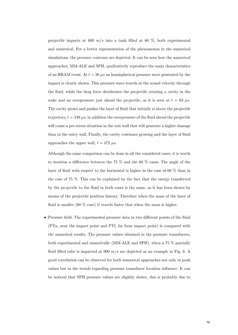
• Pressure field. The experimental pressure data in two different points of the fluid
(PTn, near the impact point and PTf, far form impact point) is compared with
the numerical results. The pressure values obtained in the pressure transducers,
both experimental and numerically (MM-ALE and SPH), when a 75 % partially
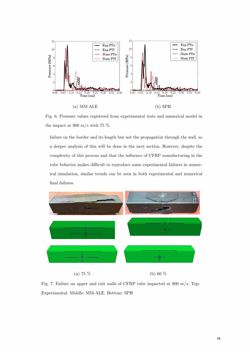
fluid filled tube is impacted at 900 m/s are depicted as an example in Fig. 6. A
good correlation can be observed for both numerical approaches not only in peak
values but in the trends regarding pressure transducer location influence. It can
be noticed that SPH pressure values are slightly slower, this is probably due to
14
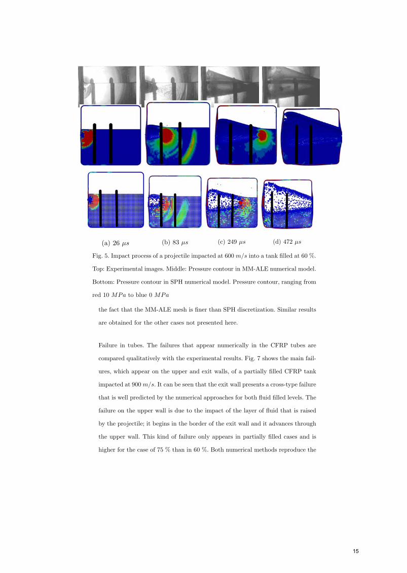
(a) 26 µs (b) 83 µs (c) 249 µs (d) 472 µs
Fig. 5. Impact process of a projectile impacted at 600 m/s into a tank filled at 60 %.
Top: Experimental images. Middle: Pressure contour in MM-ALE numerical model.
Bottom: Pressure contour in SPH numerical model. Pressure contour, ranging from
red 10 MPa to blue 0 MPa
the fact that the MM-ALE mesh is finer than SPH discretization. Similar results
are obtained for the other cases not presented here.
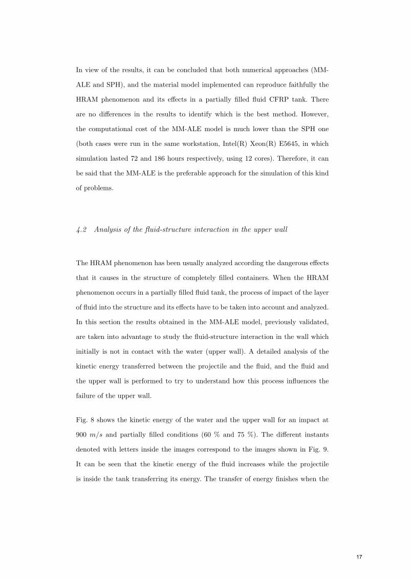
Failure in tubes. The failures that appear numerically in the CFRP tubes are
compared qualitatively with the experimental results. Fig. 7 shows the main fail-
ures, which appear on the upper and exit walls, of a partially filled CFRP tank
impacted at 900 m/s. It can be seen that the exit wall presents a cross-type failure
that is well predicted by the numerical approaches for both fluid filled levels. The
failure on the upper wall is due to the impact of the layer of fluid that is raised
by the projectile; it begins in the border of the exit wall and it advances through
the upper wall. This kind of failure only appears in partially filled cases and is
higher for the case of 75 % than in 60 %. Both numerical methods reproduce the
15
(a) MM-ALE (b) SPH
Fig. 6. Pressure values registered from experimental tests and numerical model in
the impact at 900 m/s with 75 %.
failure on the border and its length but not the propagation through the wall, so
a deeper analysis of this will be done in the next section. However, despite the
complexity of this process and that the influence of CFRP manufacturing in the
tube behavior makes difficult to reproduce same experimental failures in numer-
ical simulation, similar trends can be seen in both experimental and numerical
final failures.
(a) 75 % (b) 60 %
Fig. 7. Failure on upper and exit walls of CFRP tube impacted at 900 m/s. Top:
Experimental. Middle: MM-ALE. Bottom: SPH
16
In view of the results, it can be concluded that both numerical approaches (MM-
ALE and SPH), and the material model implemented can reproduce faithfully the
HRAM phenomenon and its effects in a partially filled fluid CFRP tank. There
are no differences in the results to identify which is the best method. However,
the computational cost of the MM-ALE model is much lower than the SPH one
(both cases were run in the same workstation, Intel(R) Xeon(R) E5645, in which
simulation lasted 72 and 186 hours respectively, using 12 cores). Therefore, it can
be said that the MM-ALE is the preferable approach for the simulation of this kind
of problems.
4.2 Analysis of the fluid-structure interaction in the upper wall
The HRAM phenomenon has been usually analyzed according the dangerous effects
that it causes in the structure of completely filled containers. When the HRAM
phenomenon occurs in a partially filled fluid tank, the process of impact of the layer
of fluid into the structure and its effects have to be taken into account and analyzed.
In this section the results obtained in the MM-ALE model, previously validated,
are taken into advantage to study the fluid-structure interaction in the wall which
initially is not in contact with the water (upper wall). A detailed analysis of the
kinetic energy transferred between the projectile and the fluid, and the fluid and
the upper wall is performed to try to understand how this process influences the
failure of the upper wall.
Fig. 8 shows the kinetic energy of the water and the upper wall for an impact at
900 m/s and partially filled conditions (60 % and 75 %). The different instants
denoted with letters inside the images correspond to the images shown in Fig. 9.
It can be seen that the kinetic energy of the fluid increases while the projectile
is inside the tank transferring its energy. The transfer of energy finishes when the
17
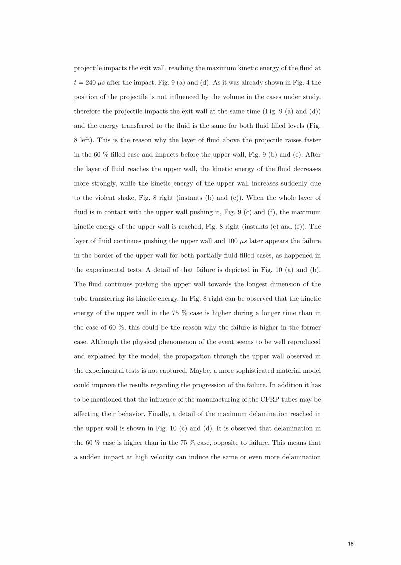
projectile impacts the exit wall, reaching the maximum kinetic energy of the fluid at
t = 240 µs after the impact, Fig. 9 (a) and (d). As it was already shown in Fig. 4 the
position of the projectile is not influenced by the volume in the cases under study,
therefore the projectile impacts the exit wall at the same time (Fig. 9 (a) and (d))
and the energy transferred to the fluid is the same for both fluid filled levels (Fig.
8 left). This is the reason why the layer of fluid above the projectile raises faster
in the 60 % filled case and impacts before the upper wall, Fig. 9 (b) and (e). After
the layer of fluid reaches the upper wall, the kinetic energy of the fluid decreases
more strongly, while the kinetic energy of the upper wall increases suddenly due
to the violent shake, Fig. 8 right (instants (b) and (e)). When the whole layer of
fluid is in contact with the upper wall pushing it, Fig. 9 (c) and (f), the maximum
kinetic energy of the upper wall is reached, Fig. 8 right (instants (c) and (f)). The
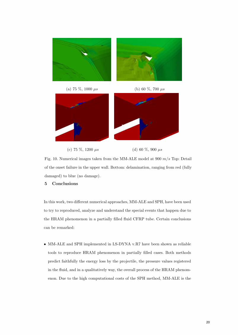
layer of fluid continues pushing the upper wall and 100 µs later appears the failure
in the border of the upper wall for both partially fluid filled cases, as happened in
the experimental tests. A detail of that failure is depicted in Fig. 10 (a) and (b).
The fluid continues pushing the upper wall towards the longest dimension of the
tube transferring its kinetic energy. In Fig. 8 right can be observed that the kinetic
energy of the upper wall in the 75 % case is higher during a longer time than in
the case of 60 %, this could be the reason why the failure is higher in the former
case. Although the physical phenomenon of the event seems to be well reproduced
and explained by the model, the propagation through the upper wall observed in
the experimental tests is not captured. Maybe, a more sophisticated material model
could improve the results regarding the progression of the failure. In addition it has
to be mentioned that the influence of the manufacturing of the CFRP tubes may be
affecting their behavior. Finally, a detail of the maximum delamination reached in
the upper wall is shown in Fig. 10 (c) and (d). It is observed that delamination in
the 60 % case is higher than in the 75 % case, opposite to failure. This means that
a sudden impact at high velocity can induce the same or even more delamination
18
than an impact at a slower velocity and more mass, which does not mean that the
final failure will be lower.
(a) Fluid kinetic energy (b) Upper wall kinetic energy
Fig. 8. Kinetic energies for the impact at 900 m/s taken from the MM-ALE model
(a) 75 %, 240 µs (b) 75 %, 600 µs (c) 75 %, 850 µs
(d) 60 %, 240 µs (e) 60 %, 350 µs (f) 60 %, 600 µs
Fig. 9. Vertical velocity contours, ranging from red 300 m/s to blue −300 m/s, taken
from the MM-ALE model. Top: 75 % filled case impacted at 900 m/s. Bottom: 60 %
filled case impacted at 900 m/s
19
(a) 75 %, 1000 µs (b) 60 %, 700 µs
(c) 75 %, 1200 µs (d) 60 %, 900 µs
Fig. 10. Numerical images taken from the MM-ALE model at 900 m/s Top: Detail
of the onset failure in the upper wall. Bottom: delamination, ranging from red (fully
damaged) to blue (no damage).
5 Conclusions
In this work, two different numerical approaches, MM-ALE and SPH, have been used
to try to reproduced, analyze and understand the special events that happen due to
the HRAM phenomenon in a partially filled fluid CFRP tube. Certain conclusions
can be remarked:
• MM-ALE and SPH implemented in LS-DYNA v.R7 have been shown as reliable
tools to reproduce HRAM phenomenon in partially filled cases. Both methods
predict faithfully the energy loss by the projectile, the pressure values registered
in the fluid, and in a qualitatively way, the overall process of the HRAM phenom-
enon. Due to the high computational costs of the SPH method, MM-ALE is the
20
suggested approach in this kind of problems.
• The CFRP model implemented using a user subroutine and a cohesive interaction
reproduces the main experimental failures that appear in partially filled fluid
tubes subjected to impact. The cross-shaped failure that appears in the exit wall
is well predicted. The trends and the length regarding the failure of the wall which
initially is not in contact with the water (upper wall) and that only appears in
partially fluid filled cases impacted at 900 m/s, are well predicted, whereas the
progression of the failure in that wall is not adequately reproduced.
• The impact process of a layer of fluid raised by the projectile movement inside a
partially filled tank has been analyzed in order to understand its importance and
influence in the failure effects of the CFRP structure. It has been shown that the
main responsible of the upper wall failure is the kinetic energy of that layer of
fluid and that it has to be taken into account for survivability designs.
Acknowledgements
This research was done with the financial support of the Spanish Ministry of Ed-
ucation under Project reference DPI2010-15123 and of the Region of Madrid and
University Carlos III of Madrid under Project reference CCG10-UC3M/DPI-4694.
References
[1] Lopez-Puente J, Zaera R, Navarro C. An analytical model for high velocity
impacts on thin CFRPs woven laminates. Int J Solids Struct 2007;44:2837-51.
[2] Airoldi A, Cacchione B. Modelling of impact forces and pressures in lagrangian
bird strike analyses. Int J Impact Eng 2006;32:1651-77.
21
[3] Anghileri M, Castelleti LML, Invernizzi F, Mascheroni M. A survey of numerical
models for hail impact analysis. Int J Impact Eng 2005;31:929-44.
[4] Pernas-Sanchez J, Pedroche DA, Varas D, Lopez-Puente J, Zaera R. Numerical
modeling of ice behavior under high velocity impacts. Int J Solids Struct
2012;49(14):1919-27.
[5] Mines RAW, McKown S, Birch RS. Impact of aircraft rubber tyre fragments
on aluminium alloy plates: I-experimental. Int J Impact Eng 2007;34:627-46.
[6] Varas D, Zaera R, Lopez-Puente J. Experimental study of fluid-filled tubes
subjected to high-velocity impact. Compos Struct 2011;93(10):2598-609
[7] Artero-Guerrero JA, Pernas-Sanchez J ,Varas D, Lopez-Puente J. Numerical
Analysis of CFRP fluid-filled tubes subjected to high velocity impact. Compos
Struct 2013;96:286-97
[8] Varas D, Zaera R, Lopez-Puente J. Numerical modelling of the Hydrodynamic
Ram phenomenon. Int J Impact Eng 2009;36:363-74.
[9] Boyd R, Royles R, El-Deeb KMM. Simulation and validation of UNDEX
phenomena relating to axisymmetric structures. Sixth international LS-DYNA
users conference similation. Dearborn (Michigan). April 2000.
[10] Hallquist JO. LS-DYNA Theory Manual. Livermore Software Technology
Company. March 2006.
[11] Hou JP, Petrinic N, Ruiz C, Hallett SR. Prediction of impact damage in
composite plates. Compos Sci Technol 2000;60(2):273-81.
[12] Lopez-Puente J, Zaera R, Navarro C. Experimental and numerical analysis of
normal and oblique ballistic impacts on thin carbon/epoxy woven laminates.
Compos Part A-Appl S 2008;39:374-87.
22
[13] Camanho PP, Davila CG. Mixed-Mode decohesion finite elements for the
simulation of delamination in composite materials. Tech Report NASA/TM-
2002-211737 2002:1-37.
[14] Turon A, Camanho PP, Costa J, Renart J. Accurate simulation of delamination
growth under mixed-mode loading using cohesive elements: Definition of
interlaminar strengths and elastic stiffness. Compos Struct 2010;92(8):1857-64.
[15] Shi Y, Swait T, Soutis C. Modelling damage evolution in composite laminates
subjected to low velocity impact. Compos Struct 2012;94(9):2902-13.
[16] Gonzalez EV, Maimı P, Camanho PP, Turon A, Mayugo JA. Simulation of
drop-weight impact and compression after impact tests on composite laminates.
Compos Struct 2012;94(11):3364-78.
[17] Varas D, Artero-Guerrero JA, Pernas-Sanchez J, Lopez-Puente J. Analysis of
high velocity impacts of steel cylinders on thin carbon/epoxy woven laminates.
Compos Struct 2013;95:623-29
[18] Lopez-Puente J, Zaera R, Navarro C. High energy impact on woven laminate.
J Phys IV 2003;110:639-44.
23