installation and operation guide ibm pos 4694
DESCRIPTION
IBM POS 4694TRANSCRIPT

4694 Point-of-Sale Terminal
Installation and Operation Guide
SA27-4228-03
���


4694 Point-of-Sale Terminal
Installation and Operation Guide
SA27-4228-03
���

NoteBefore using this information and the product it supports, be sure to read the “Appendix B. Safety information” on page 47,and the general information under “Appendix A. Notices” on page 41.
Fourth Edition (September 2001)
This edition applies to the IBM 4694 Point-of-Sale terminals. This publication is available on the IBM Retail StoresSolutions Electronic Support Web site.1. Go to www.ibm.com/solutions/retail/store
2. Select Support
3. Select Publications
You can order publications through your IBM representative or the IBM branch office that serves your locality.Publications are not stocked at the address given below.
IBM welcomes your comments. A form for readers’ comments is provided at the back of this publication. If the formhas been removed, you can send your comments to the following address:
Department CJMADesign & Information DevelopmentIBM CorporationPO Box 12195Research Triangle Park, NC 27709U.S.A.
When you send information to IBM, you grant IBM a nonexclusive right to use or distribute whatever information yousupply in any way it believes appropriate without incurring any obligation to you.
© Copyright International Business Machines Corporation 1999, 2001. All rights reserved.US Government Users Restricted Rights – Use, duplication or disclosure restricted by GSA ADP Schedule Contractwith IBM Corp.

Contents
Figures . . . . . . . . . . . . . . . . . . . . . . . . . . . . v
About this guide . . . . . . . . . . . . . . . . . . . . . . . . viiWho should use this guide. . . . . . . . . . . . . . . . . . . . . viiHow to use this guide . . . . . . . . . . . . . . . . . . . . . . viiRelated publications . . . . . . . . . . . . . . . . . . . . . . . vii
Summary of Changes . . . . . . . . . . . . . . . . . . . . . . ixJuly 2001 . . . . . . . . . . . . . . . . . . . . . . . . . . . ixFebruary 2001 . . . . . . . . . . . . . . . . . . . . . . . . . ixJune 2000 . . . . . . . . . . . . . . . . . . . . . . . . . . . ix
Tell us what you think . . . . . . . . . . . . . . . . . . . . . . xi
Chapter 1. Introducing the IBM 4694 Point-of-Sale Terminal . . . . . . . 1Product summary . . . . . . . . . . . . . . . . . . . . . . . . 1
Model widths . . . . . . . . . . . . . . . . . . . . . . . . . 1Processors . . . . . . . . . . . . . . . . . . . . . . . . . . 1Cover styles . . . . . . . . . . . . . . . . . . . . . . . . . 1Configuration options . . . . . . . . . . . . . . . . . . . . . . 1Regional differences . . . . . . . . . . . . . . . . . . . . . . 1
Summary of models . . . . . . . . . . . . . . . . . . . . . . . 2Locating machine information . . . . . . . . . . . . . . . . . . . 2
Features and options . . . . . . . . . . . . . . . . . . . . . . . 34690 Operating System dump switch . . . . . . . . . . . . . . . . 3Memory . . . . . . . . . . . . . . . . . . . . . . . . . . . 3LAN adapters . . . . . . . . . . . . . . . . . . . . . . . . . 4Front-panel operator controls and light emitting diodes (LEDs) . . . . . . . 4Rear panel operator controls and LEDs . . . . . . . . . . . . . . . 5
Chapter 2. System setup – Models 104, 106, and 124 . . . . . . . . . . 7
Chapter 3. System setup – Models 144, 146, and 154 . . . . . . . . . . 9Installing a keylock . . . . . . . . . . . . . . . . . . . . . . . 10Removing a lock insert . . . . . . . . . . . . . . . . . . . . . . 11Installing a blank lock insert . . . . . . . . . . . . . . . . . . . . 11Removing a blank lock insert . . . . . . . . . . . . . . . . . . . . 11
Chapter 4. System setup for Model 205 . . . . . . . . . . . . . . . 13Keylocks . . . . . . . . . . . . . . . . . . . . . . . . . . . 14
Chapter 5. System setup for Models 206, 207, and 307 . . . . . . . . . 15Keylocks . . . . . . . . . . . . . . . . . . . . . . . . . . . 16
Chapter 6. System setup for Model 245 . . . . . . . . . . . . . . . 19Keylocks . . . . . . . . . . . . . . . . . . . . . . . . . . . 20
Chapter 7. System setup for Models 246, 247, and 347 . . . . . . . . . 21Keylocks . . . . . . . . . . . . . . . . . . . . . . . . . . . 22
Chapter 8. Installing the options. . . . . . . . . . . . . . . . . . 25Removing the covers from narrow models . . . . . . . . . . . . . . . 26Removing the logic tray from wide models . . . . . . . . . . . . . . . 27
© Copyright IBM Corp. 1999, 2001 iii

Installing a hard disk drive in narrow models . . . . . . . . . . . . . . 28Installing a hard disk drive in wide models . . . . . . . . . . . . . . . 29Installing memory modules in Models 104, 106, and 124 . . . . . . . . . 30Installing memory modules in Models 144, 146, and 154 . . . . . . . . . 31Installing memory modules – Models 205, 206, 207, 245, 246, 247, 307 and 347 32Installing the 4690 OS dump switch on models with a front panel dump-switch
bracket . . . . . . . . . . . . . . . . . . . . . . . . . . . 34
Chapter 9. System configuration . . . . . . . . . . . . . . . . . 37Running the system configuration program during POST . . . . . . . . . 37Preparing and using a configuration diskette . . . . . . . . . . . . . . 37
Chapter 10. Testing the system . . . . . . . . . . . . . . . . . . 39Preliminary checklist . . . . . . . . . . . . . . . . . . . . . . . 39Problem isolation . . . . . . . . . . . . . . . . . . . . . . . . 39
Appendix A. Notices . . . . . . . . . . . . . . . . . . . . . . 41Electronic Emission Notices . . . . . . . . . . . . . . . . . . . . 42
Federal Communications Commission (FCC) Statement . . . . . . . . . 42Industry Canada Class A Emission Compliance Statement . . . . . . . . 42Avis de conformité aux normes d’Industrie Canada . . . . . . . . . . 42European Community (EC) Mark of Conformity Statement . . . . . . . . 42Germany . . . . . . . . . . . . . . . . . . . . . . . . . . 42Australia / New Zealand . . . . . . . . . . . . . . . . . . . . 43
Japanese power line harmonics compliance statement . . . . . . . . . . 43Japanese Voluntary Control Council for Interference (VCCI) Statement . . . . 43Korean Communications Statement . . . . . . . . . . . . . . . . . 44Taiwanese Class A Warning Statement . . . . . . . . . . . . . . . . 44Electrostatic Discharge (ESD) . . . . . . . . . . . . . . . . . . . 44Trademarks . . . . . . . . . . . . . . . . . . . . . . . . . . 45
Appendix B. Safety information . . . . . . . . . . . . . . . . . . 47
Glossary . . . . . . . . . . . . . . . . . . . . . . . . . . . 55
Index . . . . . . . . . . . . . . . . . . . . . . . . . . . . 61
iv 4694 Installation and Operation
||
Figures
1. 4694 front panel for narrow model with CD-ROM drive . . . . . . . . . . . . . . . . . 42. 4694 front panel for wide model with CD-ROM drive . . . . . . . . . . . . . . . . . . 53. Back panel for the 4694 Models 104, 106, and 124 . . . . . . . . . . . . . . . . . . 74. Cable Routing . . . . . . . . . . . . . . . . . . . . . . . . . . . . . . . . 85. Back panel for the 4694 Models 144, 146 and 154 . . . . . . . . . . . . . . . . . . . 96. Back Panel for the 4694 Model 205 . . . . . . . . . . . . . . . . . . . . . . . . 137. Back panel for the 4694 Model 206 and 307. . . . . . . . . . . . . . . . . . . . . 158. Back panel for the 4694 Model 207 . . . . . . . . . . . . . . . . . . . . . . . . 159. Back panel for the 4694 Model 245 . . . . . . . . . . . . . . . . . . . . . . . . 19
10. Back panel for the 4694 Model 246 and 347. . . . . . . . . . . . . . . . . . . . . 2111. Back panel for the 4694 Models 247 . . . . . . . . . . . . . . . . . . . . . . . 2112. Removing the covers from narrow models . . . . . . . . . . . . . . . . . . . . . 2613. Removing the front panel from wide models . . . . . . . . . . . . . . . . . . . . . 2714. Removing the tray from wide models . . . . . . . . . . . . . . . . . . . . . . . 2715. Installing a hard disk drive in narrow models without CD-ROM drive . . . . . . . . . . . . 2816. Installing a hard disk drive in wide models without CD-ROM drive . . . . . . . . . . . . . 2917. Removing and replacing memory modules – Models 104, 106 and 124 . . . . . . . . . . . 3018. Removing and replacing memory modules – Models 144, 146, and 154 . . . . . . . . . . 3119. Removing and replacing memory modules — Models 205, 206, 245, 246, front view . . . . . . 3220. Removing and replacing memory modules —Models 205, 206, 245, 246, rear view . . . . . . 3321. 4690 Operating System dump switch location . . . . . . . . . . . . . . . . . . . . 3422. 4690 Operating System dump switch installation on front panel. . . . . . . . . . . . . . 35
© Copyright IBM Corp. 1999, 2001 v
||
||
||||

vi 4694 Installation and Operation

About this guide
This guide explains how to install and operate the IBM 4694 Point-of-Sale Terminal.
Who should use this guideThis guide is intended for personnel responsible for installing IBM 4694Point-of-Sale Terminals.
How to use this guide“Chapter 1. Introducing the IBM 4694 Point-of-Sale Terminal” on page 1 providesgeneral information on the IBM 4694.
“Chapter 2. System setup – Models 104, 106, and 124” on page 7 providessetup and cabling instructions for Models 104, 106, 124.
“Chapter 3. System setup – Models 144, 146, and 154” on page 9 providessetup and cabling instructions for Models 144, 146, 154.
“Chapter 4. System setup for Model 205” on page 13 provides setup and cablinginstructions for Model 205.
“Chapter 5. System setup for Models 206, 207, and 307” on page 15 providessetup and cabling instructions for Models 206.
“Chapter 6. System setup for Model 245” on page 19 provides setup and cablinginstructions for Models 245.
“Chapter 7. System setup for Models 246, 247, and 347” on page 21 providessetup and cabling instructions for Models 246 of the 4694.
“Chapter 8. Installing the options” on page 25 shows how to install options onthe 4694 explains how to set the configuration options.
“Chapter 9. System configuration” on page 37 explains how to test the systemand helps with problem analysis.
Note: The guide describes models 1xx and 2xx of the 4694 Point-of-Sale Terminal.IBM no longer markets Models 0xx. However, a previous version of the IBM4694 Installation and Operation Guide, (SA27-4005) provides information onthese models.
The term 4694 refers to the 4694 Point-of-Sale Terminal.
Related publicationsTechnical manuals, software utilities, BIOs updates and softcopy books areavailable from the IBM Retail and Store Solutions Web site atwww.ibm.com/solutions/retail/store/. Follow the Support links to the IBM 4694Point-of-Sale Terminal.
© Copyright IBM Corp. 1999, 2001 vii

viii 4694 Installation and Operation

Summary of Changes
July 2001This edition provides information about Models 207, 307, 247, and 347 of the 4694Point-of-Sale Terminal
February 2001This edition provides information about Models 106 and 146 of the 4694Point-of-Sale Terminal.
June 2000This edition provides information about Models 206 and 246 of the 4694Point-of-Sale Terminal.
© Copyright IBM Corp. 1999, 2001 ix

x 4694 Installation and Operation

Tell us what you think
Your feedback is important in helping to provide the most accurate and high-qualityinformation. Please take a few moments to tell us what you think about this book.The only way for us to know if you are satisfied with our books, or how we mightimprove their quality is through feedback from customers like you. If you have anycomments about this book, please fill out one of the forms at the back of this bookand return it by mail or by giving it to an IBM representative.
If applicable, include a reference to the specific location of the text on which youare commenting. For instance, include the page or table number.
Between major revisions of this manual we may make minor technical updates. Thelatest softcopy version of this manual is available on the Publications Web page.
© Copyright IBM Corp. 1999, 2001 xi

xii 4694 Installation and Operation
Chapter 1. Introducing the IBM 4694 Point-of-Sale Terminal
This chapter provides information about the available features and options of theIBM 4694 Point-of-Sale Terminal, including memory, and local area network (LAN)connections.
Product summaryThe 4694 consists of a personal computer (PC) core with two feature card slots. Inaddition to the basic PC function, the 4694 has a built-in point-of-sale deviceadapter, and an Ethernet LAN adapter. All models except the 024, and 124 includebuilt-in video (VGA) support.
The 4694 is available in a combination of sizes, processors, covers, andconfiguration options. Additionally, models are available that address specificregional differences.
Model widthsThe 4694 Point-of-Sale Terminal is available in two widths:
v The narrow model is 312 mm (12.3 in.) wide. This width is equivalent to the widthof an IBM 50-key point-of-sale keyboard or a compact cash drawer.
v The wide model is 440 mm (17.3 in.) wide. This width is equivalent to the widthof an IBM alphanumeric point-of-sale keyboard or a standard cash drawer.
ProcessorsThe following types of processors are available:
v 16-bit processors, which include the Intel® 386SX and the IBM 486SLC/2
v 32-bit processors, which include the IBM 486SX/2, the IBM 486DX/2, the AMD5X86C, and the ST Microelectronics ST-PC
v 64-bit processors, which include the IBM 6X86-P166, the AMD K6/200, K6/266,K6-2/300,the Intel Celeron™ 566/66, and the VIA C3 866/133 and C3 550/100
Table 1 on page 2 provides a detailed description of the models and processortypes.
Cover stylesThe following cover types are available:
v Retail covers, which do not protect the system from liquid spray and spills.
v Food-service covers, which provide limited protection from liquid spray and spills.Food-service covers are available only for the narrow-footprint systems indistributed configurations.
Configuration optionsDepending on the hardware and cables that you select, you can configure the 4694as a distributed terminal (with devices that are separated from each other). You canalso configure the 4694 as integrated (with devices that are stacked together).
Regional differencesSpecial models accommodate double-byte character set (DBCS) I/O devices thatuse 24 V instead of 38 V.
© Copyright IBM Corp. 1999, 2001 1
||

Summary of modelsThis section explains the model designations, sizes, and other characteristics.
Table 1. Summary of 4694 models
ExternalProcessorBus Size Model
System UnitSize Regional Processor
EthernetSupport Publication
16-bit 001 Narrow
Worldwide
386SX
10-MbpsEthernet
IBM 4694 Installationand Operation Guide,
SA27-4005
004 Narrow 486SLC/2
024 Narrow 486SLC/2
041 Wide 386SX
044 Wide 486SLC/2
32-bit
104 Narrow
Worldwide 486SX/2,486DX/2, or
5X86C
10-MbpsEthernet
Described in thismanual.
124 Narrow
144 Wide
154 Wide DBCS
106 NarrowWorldwide ST-PC
146 Wide
64-bit
244Wide
Worldwide 6X86-P166,K6/200, or
K6/266
10-MbpsEthernet
IBM 4694 Installationand Operation Guide,SA27-4005254 DBCS
205 Narrow
Worldwide
AMDK6-2/300
Described in thismanual.
245 Wide
206 NarrowIntel Celeron
566/66
AMD10/100-Mbps
Ethernet246 Wide
207 Narrow
Worldwide
VIAC3-550/100 NSC
10/100-MbpsEthernet
247 Wide
307 Narrow VIAC3-866/133347 Wide
Note: The marketing materials may list additional models. These models representspecial bundles of features and software that are installed at the factory.These facotry-configured models are supersets of models that are listed inTable 1.
Locating machine informationYou can locate the following information on the front of the machine (behind thediskette drive door), and on the back of the machine (bottom left):
v Type (4694)
v Model number
v Serial number
Note: The remainder of this guide covers only Models 1xx 2xx, and 3xx.
2 4694 Installation and Operation
|
||
|
||||||||
||||||

Note: The Models 0xx and some models of 1xx and 2xx have been removed frommarketing. Information on Models 0xx is provided in the IBM 4694Installation and Operation Guide, SA27–4005.
Features and optionsAll models of the 4694 contain the following standard features:
v One 3.5-inch 1.44-MB diskette drive
v Two serial ports
v Two industry-standard architecture (ISA) slots as follows:
Table 2. ISA slots
Model Slots
1xx 2 ISA
2x4 1 ISA
2x5 1 ISA/PCI shared, 1 ISA
2x6, 2x7, 3x7 1 PCI, 1 ISA/PCI shared
v Ethernet LAN adapter
v One keyboard port
v One mouse port
v One parallel port (wide models only)
v 32 KB of nonvolatile memory
v Nonvolatile real-time clock
v SVGA support
The options for all models include:v Hard diskv Dynamic random access memory (DRAM) expansionv Dump switch
A CD-ROM drive is available for Models 2x5, 2x6, 2x7 and 3x7.
You can order and install any option (except the CD-ROM Drive) at a later date.
4690 Operating System dump switchThe IBM 4690 Operating System Dump Switch feature can be ordered for models1x4 and 2x4. It ships as a standard feature on models 1x6, 2x5, 2x6, 2x7, and 3x7.The purpose of the dump switch is to help with IBM 4690 Operating Systemproblem analysis. To locate the dump switch, see Figure 1 on page 4 and Figure 2on page 5.
For information about installing the dump switch, see “Chapter 8. Installing theoptions” on page 25.
MemoryThe 4694 ships with memory installed. You can expand the memory by addingmore memory modules. For more information about installing memory modules, see“Chapter 8. Installing the options” on page 25.
Chapter 1. Introducing the IBM 4694 Point-of-Sale Terminal 3
|
|
|||||

LAN adaptersThe 4694 provides an Ethernet LAN adapter on the system board. Models 1xx and2x4 have 10-Mbps Ethernet adapters that meet the IEEE 802.3i 10BASE-Tstandard. 2x5 and 2x6 models provide a dual-speed 10/100-Mbps Ethernet adapterand meet both the IEEE 802.3i 10BASE-T standard and the IEEE 802.3u100BASE-TX standard. The 2x7 and 3x7 models support 10/100-Mbps Ethernetstandards; however, these models require different software drivers than the 2x5and 2x6 models.
Like all Ethernet devices, the 4694 uses Category 3 or Category 5 unshieldedtwisted pair (UTP) cable and requires the use of a hub or switch. Category 3 UTPcable is only for 10-Mbps installations; Category 5 UTP cable is for both 10-Mbpsand 100-Mbps installations. IBM recommends Category 5 cable for all installations.100 meters (328 ft) is the maximum length of cable that is permitted between theterminal and the hub.
Obtaining the correct software driver for your LAN adapterThe LAN hardware on Models 2x5 and 2x6 is manufactured by AMD whereas theLAN hardware on machine models 2x7 and 3x7 is manufactured by NationalSemiconductor. Ensure that you obtain the correct LAN software driver for yourmachine model.
Front-panel operator controls and light emitting diodes (LEDs)Figure 1 and Figure 2 on page 5 identify the various controls and LEDs on the frontof a 4694 with a CD-ROM Drive installed.
CD-ROM eject
CD-ROM LED
CD-ROM emergency eject
Hard drive LED
Power button
Power-on LED
Diskette drive LED
Dump switch (on some models)
Figure 1. 4694 front panel for narrow model with CD-ROM drive
4 4694 Installation and Operation
|||||||
|||||

To switch power ON (after device installation and setup), open the front cover andpress the power button. The green power-on LED appears. The yellow hard diskdrive LED might blink on and off.
Some systems provide standby capability. If the operating system powermanagement software has been loaded, a brief pressing of the power button putsthe system into a standby state. A flashing green LED indicates standby. To returnthe system to the power-on state, briefly press the power button again. To switchthe system completely off, hold down the power button for 2 seconds.
The front panel might include an optional dump switch. See Figure 1 on page 4 andFigure 2. The dump switch is mounted flush with the front cover and must bepressed with something pointed, such as the tip of a pen. The dump switchprovides dump support for the 4690 Operating System and can be installed by fieldrepresentatives.
The CD-ROM drive has a normal CD-ROM eject button and, in the event of anemergency such as a power failure, an emergency eject or mechanical release.Refer to Figure 1 on page 4 and Figure 2 to locate the eject button. To use theemergency eject, insert a small solid object (for example, the end of a paper clip ortest probe) into the hole on the front of the CD-ROM Drive. This will release the CDtray.
Rear panel operator controls and LEDsTable 3 summarizes the LEDs that are located on the back panel and Table 4 onpage 6 and Table 5 on page 6 explains the terms for the models:
Table 3. Back panel LEDs
LED Number and Color 10/100 Mbps Models(2x5/2x6)
10/100-Mbps Models(2x7/3x7)
LED 1 (yellow) jabber not used
LED 2 (yellow) collision 100-Mbps mode
LED 3 (green) link/receive data 10-Mbps mode
LED 4 (green) power/transmit data activity
Diskette drive lock (on some models)
Hard drive LED
Power button
Power-on LED
CD-ROM LED
Dump switch (on some models)
Diskette drive LED
CD-ROM eject
CD-ROM emergency eject
Figure 2. 4694 front panel for wide model with CD-ROM drive
Chapter 1. Introducing the IBM 4694 Point-of-Sale Terminal 5

Table 4. Definitions for Models 2x5 and 2x6
Jabber The LAN is sending more than 512 bytes of data, or thetransmit line remains on. During normal operation, this LEDshould not be on.
Collision The LAN adapter has collided with another LAN adapter that istrying to transmit at the same time. It is normal for this LED tobe blinking.
10/100-Mbps mode The LAN adapter is operating in 100-Mbps mode.
Link/receive data The LAN adapter is seeing data on the LAN.
Power/transmit dataOn Power is ON but the LAN adapter transmit line is not
active.
Transmit dataThe two stages are:
BlinkingThe LAN adapter transmit line is active
Off Power is OFF.
Table 5. Definitions for Models 2x7 and 3x7
100 Mbps connection The terminal is successfully connected to ahub or switch and operating in 100 Mbpsmode.
10 Mbps connection The terminal is successfully connected to ahub or switch and operating in 10 Mbpsmode.
Activity Blinks when either transmit or receive activityis occurring on the link
The back panel might include an optional dump switch. The dump switch providesdump support for the 4690 Operating System.
6 4694 Installation and Operation

Chapter 2. System setup – Models 104, 106, and 124
See “Appendix B. Safety information” on page 47 and “Electronic Emission Notices”on page 42 before performing the procedures in this section.
To set up 4694 Models 104, 106, and 124, proceed as follows:
1. Place the machine on a flat, sturdy surface and remove the rear cover.
2. Plug in the device cables, as appropriate.
3. The following list defines the symbols on the back of the machine:
Plug in an external serial device, such as a scale or a scanner,here in port A. This is COM1.
Plug in a second external serial device here in port B. This isCOM2.
Plug in the SVGA display here.
Plug in the Point-of-Sale printer here.
Plug in the Point-of-Sale keyboard here.
9C/E
Plug in the Point-of-Sale scanner or other I/O device that uses a9-port cable here.
Plug in the Point-of-Sale display here.
Connect up to two Point-of-Sale cash drawers to the 4694. Plugin the first cash drawer here.
Plug in the second cash drawer here.
PowerConnector A B
1234
Figure 3. Back panel for the 4694 Models 104, 106, and 124
© Copyright IBM Corp. 1999, 2001 7
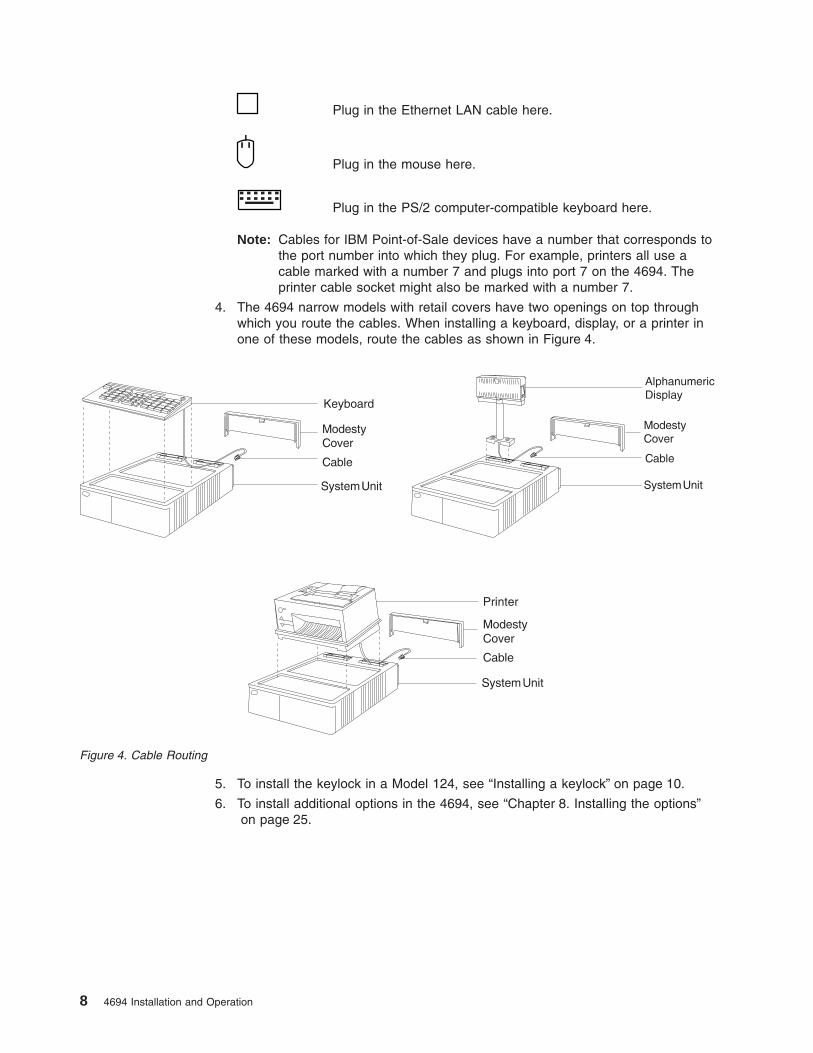
Plug in the Ethernet LAN cable here.
Plug in the mouse here.
Plug in the PS/2 computer-compatible keyboard here.
Note: Cables for IBM Point-of-Sale devices have a number that corresponds tothe port number into which they plug. For example, printers all use acable marked with a number 7 and plugs into port 7 on the 4694. Theprinter cable socket might also be marked with a number 7.
4. The 4694 narrow models with retail covers have two openings on top throughwhich you route the cables. When installing a keyboard, display, or a printer inone of these models, route the cables as shown in Figure 4.
5. To install the keylock in a Model 124, see “Installing a keylock” on page 10.
6. To install additional options in the 4694, see “Chapter 8. Installing the options”on page 25.
Figure 4. Cable Routing
8 4694 Installation and Operation

Chapter 3. System setup – Models 144, 146, and 154
See “Appendix B. Safety information” on page 47 and “Electronic Emission Notices”on page 42 before performing the procedures in this section.
To set up 4694 Models 144, 146, and 154, proceed as follows:
1. Place the machine on a flat, sturdy surface and remove the rear cover.
2. Plug in the device cables, as appropriate.The symbols are on the back of the4694 are defined in the following list:
Plug in the SVGA display here.
Plug in an external serial device, such as a scale or a scanner,here in port A. This is COM1.
Plug in a second external serial device here in port B. This isCOM2.
Parallel port. You can optionally plug in a parallel-interfacedevice here.
Plug in the Point-of-Sale printer here.
Plug in the Point-of-Sale keyboard here.
Plug in the Point-of-Sale scanner or other I/O device that uses a9-port cable here.
Plug in the Point-of-Sale display here.
You can connect up to two Point-of-Sale cash drawers to the4694. Plug in the first cash drawer here.
PowerConnector A B
1234
Figure 5. Back panel for the 4694 Models 144, 146 and 154
© Copyright IBM Corp. 1999, 2001 9

Plug in the second cash drawer here.
Plug in the Ethernet LAN cable here.
Plug in the mouse here.
Plug in the PS/2® computer-compatible keyboard here.
Note: Cables for IBM Point-of-Sale devices have a number that corresponds tothe number of the port into which they plug. For example, all printers usea cable marked with a number 7 that plugs into port 7 on the 4694. Theprinter cable socket might also be labeled with a number 7.
3. Refer to the IBM Installation and Operation Guide for Point-of-Sale Input/OutputDevices, for cable routing information.
4. To install additional options in a 4694, see “Chapter 8. Installing the options” onpage 25.
Installing a keylock1. Open the front door.
2. Insert the aligner in the empty lock cylinder. Gently turn the aligner clockwiseuntil you feel it engage the slot in the bottom of the lock cylinder.
3. Turn the aligner so that the arrow points in the direction that is shown.
4. Remove the aligner.
5. Remove the keys that came with the lock insert.
6. Insert the brass key fully into the lock insert.
7. Hold the lock and brass key so that the key points in the same direction as didthe aligner.
8. Push the lock insert and the brass key fully into the empty lock cylinder.
9. Hold the lock insert in place with your finger and remove the brass key. Thelock is installed.
10. Test the lock to ensure that it operates correctly with the keys.
11. To remove a lock insert or install a blank lock insert, see “Removing a lockinsert” on page 11.
10 4694 Installation and Operation
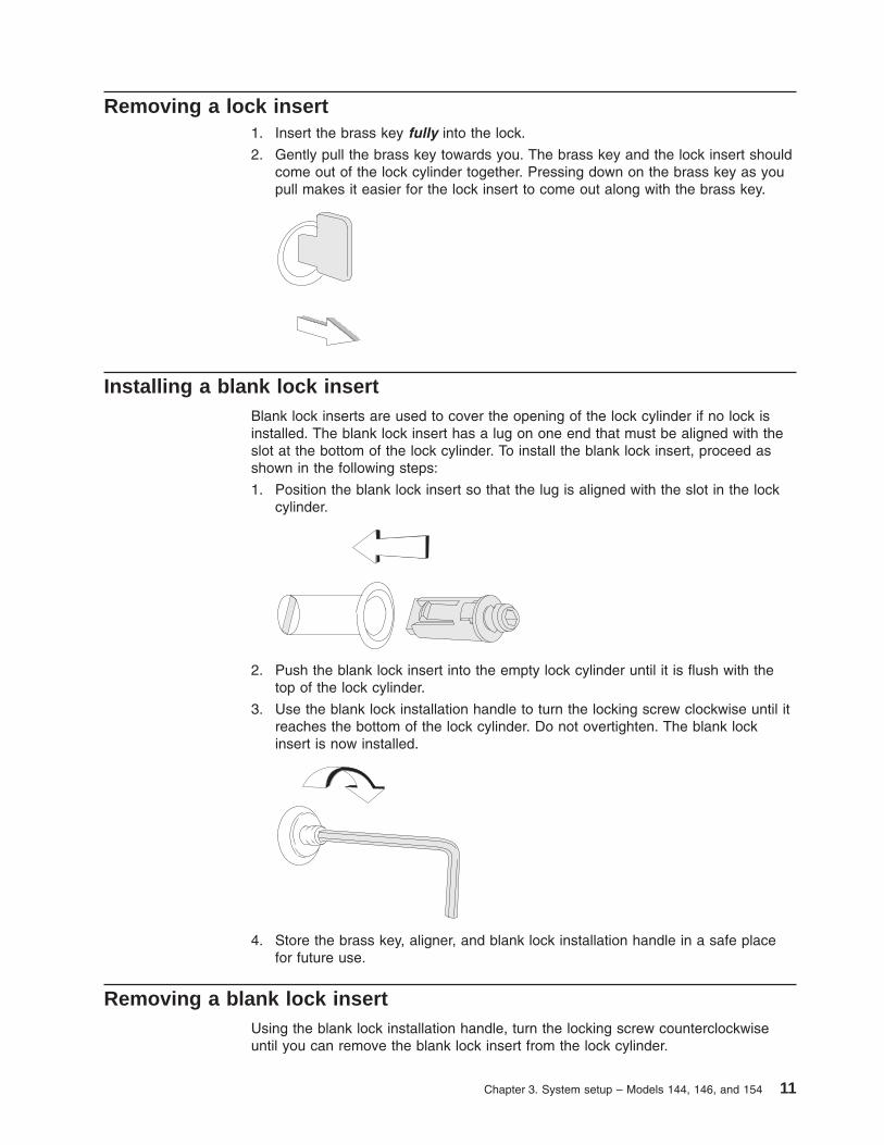
Removing a lock insert1. Insert the brass key fully into the lock.
2. Gently pull the brass key towards you. The brass key and the lock insert shouldcome out of the lock cylinder together. Pressing down on the brass key as youpull makes it easier for the lock insert to come out along with the brass key.
Installing a blank lock insertBlank lock inserts are used to cover the opening of the lock cylinder if no lock isinstalled. The blank lock insert has a lug on one end that must be aligned with theslot at the bottom of the lock cylinder. To install the blank lock insert, proceed asshown in the following steps:
1. Position the blank lock insert so that the lug is aligned with the slot in the lockcylinder.
2. Push the blank lock insert into the empty lock cylinder until it is flush with thetop of the lock cylinder.
3. Use the blank lock installation handle to turn the locking screw clockwise until itreaches the bottom of the lock cylinder. Do not overtighten. The blank lockinsert is now installed.
4. Store the brass key, aligner, and blank lock installation handle in a safe placefor future use.
Removing a blank lock insertUsing the blank lock installation handle, turn the locking screw counterclockwiseuntil you can remove the blank lock insert from the lock cylinder.
Chapter 3. System setup – Models 144, 146, and 154 11

To install additional options in a 4694, see “Chapter 8. Installing the options” onpage 25 .
12 4694 Installation and Operation

Chapter 4. System setup for Model 205
See “Appendix B. Safety information” on page 47 and “Electronic Emission Notices”on page 42 before performing the procedures in this section.
To set up a 4694 Model 205, proceed as follows:
1. Place the 4694 on a flat, sturdy surface and remove the rear cover.
2. Plug in the device cables, as appropriate. Review the symbols on the back ofthe 4694 as follows:
Plug in the SVGA display here.
Plug in an external serial device, such as a scale and ascanner, here in port A. This is COM1.
Plug in a second external serial device here in port B. This isCOM2.
9A
Plug in the Point-of-Sale scanner or other I/O device that uses a9-port cable here.
9B
Plug in a Point-of-Sale scanner or other I/O device that uses a9-port cable here.
Plug in the Point-of-Sale Printer here.
Plug in the Point-of-Sale keyboard here.
9C/E
Plug in the Point-of-Sale scanner or other I/O device that uses a9-port cable here.
Plug in the Point-of-Sale display here.
PowerConnector A B
1234
Figure 6. Back Panel for the 4694 Model 205
© Copyright IBM Corp. 1999, 2001 13

Connect up to two Point-of-Sale cash drawers to the 4694. Plugin the first cash drawer here.
Plug in the second cash drawer here.
Plug in the Ethernet LAN cable here.
Plug in the mouse here.
Plug in the PS/2 computer-compatible keyboard here.
Note: Cables for IBM Point-of-Sale devices are marked with a number thatcorresponds to the number of the port into which they plug. For example,printers all use a cable that is marked with a number 7 and plugs intoport 7 on the 4694. The printer cable socket might also be marked with anumber 7.
3. Refer to the Installation and Operation Guide for Point-of-Sale Input/OutputDevices, for cable routing information.
KeylocksFor more information about keylocks, refer to the following sections:
“Installing a keylock” on page 10“Removing a lock insert” on page 11“Installing a blank lock insert” on page 11“Removing a blank lock insert” on page 11
To install additional options in the 4694, see “Chapter 8. Installing the options” onpage 25 .
14 4694 Installation and Operation
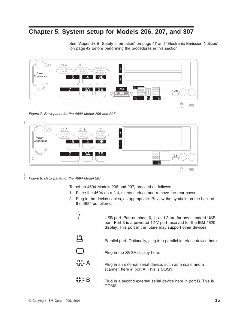
Chapter 5. System setup for Models 206, 207, and 307
See “Appendix B. Safety information” on page 47 and “Electronic Emission Notices”on page 42 before performing the procedures in this section.
To set up 4694 Models 206 and 207, proceed as follows:
1. Place the 4694 on a flat, sturdy surface and remove the rear cover.
2. Plug in the device cables, as appropriate. Review the symbols on the back ofthe 4694 as follows:
USB port. Port numbers 0, 1, and 2 are for any standard USBport. Port 3 is a powered 12-V port reserved for the IBM 4820display. This port in the future may support other devices
Parallel port. Optionally, plug in a parallel-interface device here.
Plug in the SVGA display here.
Plug in an external serial device, such as a scale and ascanner, here in port A. This is COM1.
Plug in a second external serial device here in port B. This isCOM2.
PowerConnector 4
3B7 1234
BA
5 9E
3A
3
12v
210
Figure 7. Back panel for the 4694 Model 206 and 307
PowerConnector 4
3B7 1234
BA
5 9E
3A
10
Figure 8. Back panel for the 4694 Model 207
© Copyright IBM Corp. 1999, 2001 15
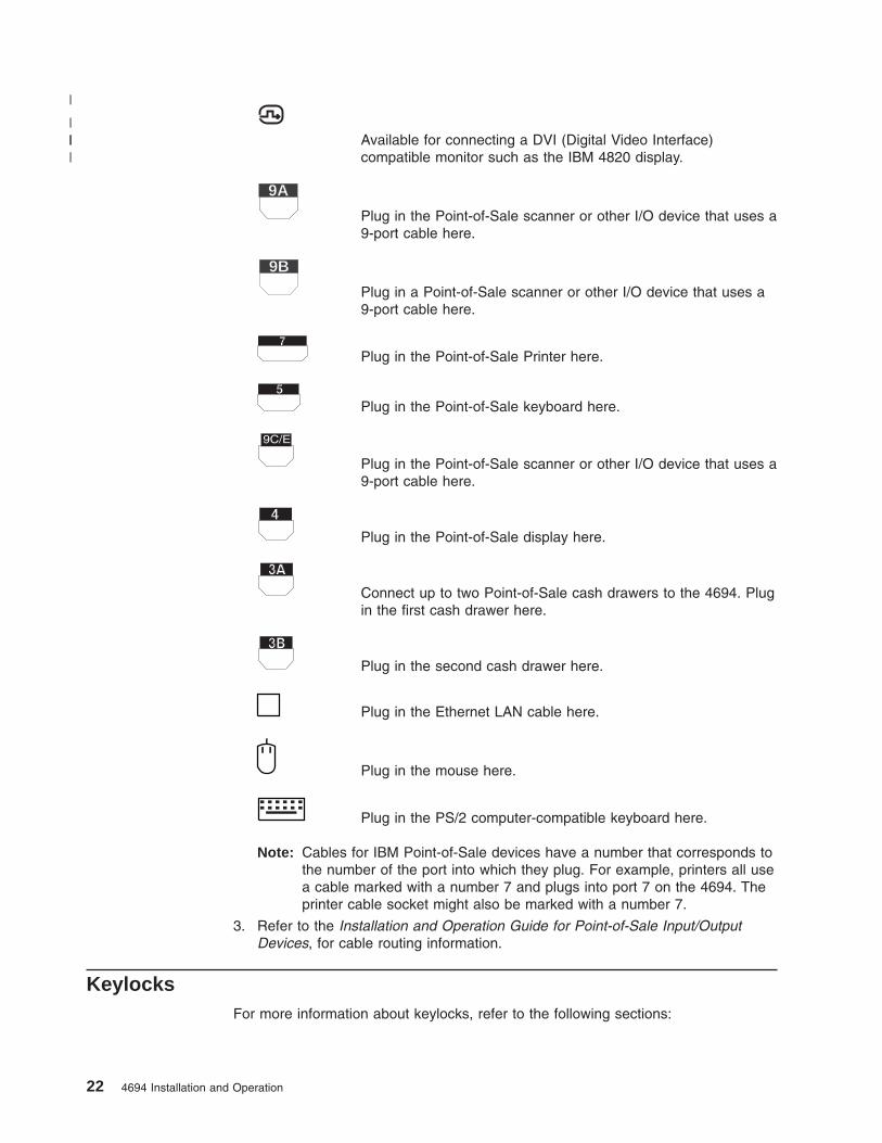
|
||

Available for connecting a DVI (Digital Video Interface)compatible monitor such as the IBM 4820 display.
9A
Plug in the Point-of-Sale scanner or other I/O device that uses a9-port cable here.
Plug in the Point-of-Sale Printer here.
Plug in the Point-of-Sale keyboard here.
9C/E
Plug in the Point-of-Sale scanner or other I/O device that uses a9-port cable here.
Plug in the Point-of-Sale display here.
Connect up to two Point-of-Sale cash drawers to the 4694. Plugin the first cash drawer here.
Plug in the second cash drawer here.
Plug in the Ethernet LAN cable here.
Plug in the mouse here.
Plug in the PS/2 computer-compatible keyboard here.
Note: Cables for IBM Point-of-Sale devices are marked with a number thatcorresponds to the number of the port into which they plug . Forexample, printers all use a cable that is marked with a number 7 andplugs into port 7 on the 4694. The printer cable socket might also bemarked with a number 7.
3. Refer to the Installation and Operation Guide for Point-of-Sale Input/OutputDevices, for cable routing information.
KeylocksFor more information about keylocks, refer to the following sections:
v “Installing a keylock” on page 10.
v “Removing a lock insert” on page 11.
v “Installing a blank lock insert” on page 11.
v “Removing a blank lock insert” on page 11,
16 4694 Installation and Operation
|||

To install additional options in the 4694, see “Chapter 8. Installing the options” onpage 25 .
Chapter 5. System setup for Models 206, 207, and 307 17

18 4694 Installation and Operation

Chapter 6. System setup for Model 245
See “Appendix B. Safety information” on page 47 and “Electronic Emission Notices”on page 42 before performing the procedures in this section.
To set up a 4694 Model 245, proceed as follows:
1. Place the 4694 on a flat, sturdy surface and remove the rear cover.
2. Plug in the device cables, as appropriate. Review the symbols on the back ofthe 4694 as follows:
USB port (available on some models).
Second USB port (available on some models).
Parallel port. Optionally, plug in a parallel-interface device here.
Plug in the SVGA display here.
Plug in an external serial device, such as a scale and ascanner, here in port A. This is COM1.
Plug in a second external serial device here in port B. This isCOM2.
9A
Plug in the Point-of-Sale scanner or other I/O device that uses a9-port cable here.
9B
Plug in a Point-of-Sale scanner or other I/O device that uses a9-port cable here.
Plug in the Point-of-Sale Printer here.
PowerConnector A B
12349/B9/A
1 2
Figure 9. Back panel for the 4694 Model 245
© Copyright IBM Corp. 1999, 2001 19

Plug in the Point-of-Sale keyboard here.
9C/E
Plug in the Point-of-Sale scanner or other I/O device that uses a9-port cable here.
Plug in the Point-of-Sale display here.
Connect up to two Point-of-Sale cash drawers to the 4694. Plugin the first cash drawer here.
Plug in the second cash drawer here.
Plug in the Ethernet LAN cable here.
Plug in the mouse here.
Plug in the PS/2 computer-compatible keyboard here.
Note: The number on the label of an IBM Point-of-Sale device cablecorresponds with a number on the port into which they plug. Forexample, printers all use a cable marked with a number 7 and plugs intoport 7 on the 4694. The printer cable socket might also be marked with anumber 7.
3. Refer to the Installation and Operation Guide for Point-of-Sale Input/OutputDevices, for cable routing information.
KeylocksFor more information about keylocks, refer to the following sections:
“Installing a keylock” on page 10“Removing a lock insert” on page 11“Installing a blank lock insert” on page 11“Removing a blank lock insert” on page 11
To install additional options in the 4694, see “Chapter 8. Installing the options” onpage 25.
20 4694 Installation and Operation

Chapter 7. System setup for Models 246, 247, and 347
See “Appendix B. Safety information” on page 47 and “Electronic Emission Notices”on page 42 before performing the procedures in this section.
To set up 4694 Models 246, 247, and 347, proceed as follows:
1. Place the 4694 on a flat, sturdy surface and remove the rear cover.
2. Plug in the device cables, as appropriate. The symbols on the back of the 4694are defined as follows:
USB port. Port numbers 0, 1, and 2 are for any standard USBport. Port 3 is a powered 12-V port reserved for the IBM 4820display. This port in the future may support other devices
Parallel port. Optionally, plug in a parallel-interface device here.
Plug in the SVGA display here.
Plug in an external serial device, such as a scale and ascanner, here in port A. This is COM1.
Plug in a second external serial device here in port B. This isCOM2.
PowerConnector
3B3A5712v1234
BA
9C/E9B9A4
3
21
0
Figure 10. Back panel for the 4694 Model 246 and 347
PowerConnector
3B3A571234
BA
9C/E9B9A4
1
0
Figure 11. Back panel for the 4694 Models 247
© Copyright IBM Corp. 1999, 2001 21
|
||
Available for connecting a DVI (Digital Video Interface)compatible monitor such as the IBM 4820 display.
9A
Plug in the Point-of-Sale scanner or other I/O device that uses a9-port cable here.
9B
Plug in a Point-of-Sale scanner or other I/O device that uses a9-port cable here.
Plug in the Point-of-Sale Printer here.
Plug in the Point-of-Sale keyboard here.
9C/E
Plug in the Point-of-Sale scanner or other I/O device that uses a9-port cable here.
Plug in the Point-of-Sale display here.
Connect up to two Point-of-Sale cash drawers to the 4694. Plugin the first cash drawer here.
Plug in the second cash drawer here.
Plug in the Ethernet LAN cable here.
Plug in the mouse here.
Plug in the PS/2 computer-compatible keyboard here.
Note: Cables for IBM Point-of-Sale devices have a number that corresponds tothe number of the port into which they plug. For example, printers all usea cable marked with a number 7 and plugs into port 7 on the 4694. Theprinter cable socket might also be marked with a number 7.
3. Refer to the Installation and Operation Guide for Point-of-Sale Input/OutputDevices, for cable routing information.
KeylocksFor more information about keylocks, refer to the following sections:
22 4694 Installation and Operation
|
||||

“Installing a keylock” on page 10“Installing a blank lock insert” on page 11“Removing a lock insert” on page 11“Removing a blank lock insert” on page 11
To install additional options in the 4694, see “Chapter 8. Installing the options” onpage 25.
Chapter 7. System setup for Models 246, 247, and 347 23

24 4694 Installation and Operation

Chapter 8. Installing the options
See “Appendix B. Safety information” on page 47 and “Electronic Emission Notices”on page 42 before performing the procedures in this section.
This chapter contains information about installing options in the 4694.
The following option is available to expand the capabilities of the 4694:v Memory modules
Each set of instructions applies to all models within an indicated group. See Table 1on page 2 if you have any question as to which models are covered.
Note: While performing the procedures in this chapter, retain all screws, parts, andworking devices for future reinstallation. Also note the location andconfiguration of cable connections and plug connections for all devicesbefore disconnecting them.
© Copyright IBM Corp. 1999, 2001 25

Removing the covers from narrow models1. Power OFF the 4694 and the attached devices that have a power ON/OFF
switch, and disconnect any power cables from electrical outlets.
2. Remove the rear cover by sliding it upward.
3. Take note of the cable connections for all I/O devices before disconnectingthem.
4. Disconnect all external device cables from the back of the 4694.
5. Disconnect and remove the keyboard, printer, display, and any other I/O devicesfrom the top of the system unit.
6. Pull down on the spring catch at the rear of and under the top cover, and slidethe cover to the rear until it stops.
7. Flex the sides of the top cover slightly outward and pull upward until the coveris free.
8. To remove the top metal cover, remove the mounting screw and lift the metalcover to an angle of about 30 degrees. Remove the edge of the metal coverfrom the base by moving the cover in the direction that is shown. Retain themounting screw and the metal cover.
9. To reinstall the covers, reverse this procedure.
Figure 12. Removing the covers from narrow models
26 4694 Installation and Operation

Removing the logic tray from wide models1. Power OFF the 4694 and the attached devices that have a power ON/OFF
switch, and disconnect any power cables from outlets.
2. To remove the front panel, press the release buttons on each side (one at atime). Gently pull forward on each side of the panel and press the releaselatches until both sides release from the latches.
3. Release the latch and pull the logic tray forward and out of the terminal.
4. To reinstall the cover, reverse this procedure.
Figure 13. Removing the front panel from wide models
Figure 14. Removing the tray from wide models
Chapter 8. Installing the options 27

Installing a hard disk drive in narrow models1. Remove the covers. See “Removing the covers from narrow models” on
page 26.
2. Remove the spline from the chassis.
3. Note the locations of the cable and of the connector. Disconnect the cables fromthe diskette drive and the hard disk drive.
4. Using a flat-blade screwdriver, release the locking catch on the file bucket. SeeFigure 15. At the same time, slide the file bucket back until the bucket clears theguides.
5. After the file bucket clears the guides, lift it up and out of the chassis.
6. Slide the hard disk drive forward into the lower bracket until it stops. Align thescrew holes and fasten the hard disk drive to the bracket with the four screwsthat are supplied.
7. To reinstall the file bucket in the terminal, reverse this procedure. Verify that allguides and the locking catch are fully engaged. Reconnect all cables.
Diskette DriveGuides
LockingCatch File Bucket
Guides
Diskette DriveCable Connector
PowerSupply
Fixed DriveCableConnector
FixedDrive
Figure 15. Installing a hard disk drive in narrow models without CD-ROM drive
28 4694 Installation and Operation

Installing a hard disk drive in wide models1. Remove the covers. See “Removing the logic tray from wide models” on
page 27.
2. Note the locations of the cable and of the connector. Disconnect the cables fromthe diskette drive and the hard disk drive (if one is already installed).
3. Press the tabs at the rear of the hard disk drive and slide the hard disk drivetoward the rear. Remove the hard disk drive.
4. Remove the two screws on each side of the hard disk.
5. Fasten the two brackets to the hard disk drive with the screws.
6. Slide the hard disk drive forward into the upper bracket until it snaps into place.
7. Reconnect all cables.
Diskette DriveGuides
File Bucket
Guides
Diskette DriveCable Connector
PowerSupply
Hard DriveCableConnector
HardDrive
Figure 16. Installing a hard disk drive in wide models without CD-ROM drive
Chapter 8. Installing the options 29

Installing memory modules in Models 104, 106, and 124The 4694 comes with memory installed. Additional or replacement memory isavailable in modules. Memory is installed in any combination, however, install thememory modules in sequential order, starting with socket SM1.
There are four 72-pin memory module sockets on the system board.
1. Remove the covers. See “Removing the covers from narrow models” onpage 26.
2. Remove any installed adapter cards.
3. If you are exchanging memory modules that are already installed, remove thesefirst by releasing the retainers and pivoting the memory modules to the rear.
4. With the components on the new memory module pointing towards the front ofthe 4694, insert the module into the socket at an angle. Pivot the module upuntil it latches into the retainer.
Figure 17. Removing and replacing memory modules – Models 104, 106 and 124
30 4694 Installation and Operation

Installing memory modules in Models 144, 146, and 154The 4694 comes with memory installed. Additional or replacement memory isavailable in modules. Memory is installed in any combination, however, install it insequential order, starting with socket SM1.
1. Remove the logic tray. See “Removing the logic tray from wide models” onpage 27.
2. Remove any installed adapter cards.
3. If you are exchanging memory modules that are already installed, remove thesefirst by releasing the retainers and pivoting the modules to the rear.
4. With the components on the new memory module pointing towards the front ofthe 4694, insert the module into the socket at an angle. Pivot the module upuntil it latches into the retainer.
Memory Modules
Front Front
Memory Modules
Memory Modules
Front
Figure 18. Removing and replacing memory modules – Models 144, 146, and 154
Chapter 8. Installing the options 31

Installing memory modules – Models 205, 206, 207, 245, 246, 247, 307and 347
The 4694 Models 205, 206, 207, 245, 246, 247, 307 and 347 are the 64-bit10/100-Mbps Ethernet models. These machines come with memory installed.Memory is available in modules. There are two memory module sockets on thesystem board.
Memory Modules
Front Front
Memory Modules
Figure 19. Removing and replacing memory modules — Models 205, 206, 245, 246, frontview
32 4694 Installation and Operation
|
|
||||||

1. Remove the cover. See “Removing the covers from narrow models” on page 26or “Removing the logic tray from wide models” on page 27, depending on yourmodel.
2. Remove any installed adapter cards.
3. If you are exchanging memory modules that are already installed, remove thesefirst by releasing the retainers and pulling the modules straight upward.
4. Position the new memory module so that the notches on the bottom line up withthe keys in the socket. Insert the module into the socket. Press straight downuntil it snaps into place.
5. Pivot the retainers up against the module until they snap into place.
Retainer
Figure 20. Removing and replacing memory modules —Models 205, 206, 245, 246, rear view
Chapter 8. Installing the options 33
|
|||
|||
|
|||
|||
|

Installing the 4690 OS dump switch on models with a front paneldump-switch bracket
An optional dump switch provides dump support for the 4690 Operating System.The dump switch option is field-installable and consists of the following:
v A switch, a nut, and a washer that fastens the dump switch to the front panel
v A riser card
v A cable that connects the switch to the riser card
These instructions apply to 4694 machines built in 1999 or later. Another way toidentify these machines is by the presence of a dump switch bracket on the frontpanel.
Figure 21. 4690 Operating System dump switch location
34 4694 Installation and Operation

1. Remove the covers. See “Removing the covers from narrow models” onpage 26 or “Removing the logic tray from wide models” on page 27, dependingon your model.
2. Remove the two screws that attach the spline and lift it off the chassis.
3. Unplug the riser card from the system board and remove it from the machine.
4. From behind the front panel, push the dump switch through the opening in thedump switch bracket.
5. Use the supplied nut and washer to fasten the dump switch to the bracket
6. Remove the backing from the self-adhesive plastic clip. Stick the clip to thefloor of the machine just behind the front panel and directly under the path ofthe spline.
7. Replace the existing riser card with the riser card that is included with thedump switch.
8. Route the cable through the plastic clip by snapping the cable into the clip.
9. Plug the dump switch cable into the riser card.
10. Reinstall the spline, making sure that the two spline flanges hold the riser cardin place. Fasten the spline with the two screws.
11. Replace the covers.
Figure 22. 4690 Operating System dump switch installation on front panel
Chapter 8. Installing the options 35

36 4694 Installation and Operation

Chapter 9. System configuration
This chapter describes how to set the system configuration.
Usually, you do not need to run the system configuration program because theterminal does most configuration activities automatically. However, you need toperform system configuration in the following cases:v You want to change some of the POS subsystem-default memory addressing.v You want your terminal to boot off a local area network (LAN).
Two methods are available for configuring your system:
v If a video adapter and a standard PS/2 keyboard (or the alphanumeric POSkeyboard connected to the PS/2 keyboard port) are installed, press F2 while thepower-on self-test (POST) is running to invoke the system configuration program.
v If a video adapter and PS/2 keyboard are not attached, you must prepare, andthen boot from, a special configuration diskette.
Running the system configuration program during POSTIf the 4694 has a monitor and an alphanumeric keyboard, you can configure it asdescribed in the following steps:
1. Power on the 4694.
2. Press F2 during POST when the system prompts you.
Note: The program sets many configuration values automatically when youpower ON the terminal and are not configurable. The POS adapteroptions refer to memory addresses and interrupt levels that are used bythe integrated POS adapter. Do not change these values unless youhave conflicts with installed adapter cards.
3. Follow the instructions on the screen.
Preparing and using a configuration disketteThe DOS program, CS4694.EXE, is an alternative to configuring during POST. Thisprogram is a part of the 4694 CMOS Setup Configuration Utility. You can downloadit from the Support section of the IBM Retail Store Solutions Web site:
://www.ibm.com/solutions/retail/store/
The CS4694 program runs on the 4694 or on any available PC. Use it to edit the4694 BIOS settings. Before exiting CS4694, press the SAVE function key to savethe BIOS values in a file for later use by CMOSSET.COM, which is also part of thedownloaded package. Then run CMOSSET to update the 4694 CMOS.
The new utility works differently from the original CSETUP.EXE utility. The originalutility created a boot diskette that loaded the values directly into the CMOS of the4694 and ran only on 4694 hardware.
To generate the configuration diskette, follow the instructions in the READ.ME file inthe downloaded package.
© Copyright IBM Corp. 1999, 2001 37

38 4694 Installation and Operation

Chapter 10. Testing the system
Software errors or hardware failures can cause problems with the 4694. Thischapter contains problem analysis tables to help determine the cause of a problemand how to solve it.
When you power ON the 4694, the system runs a power-on self-test (POST). If thePOST does not find any errors, the system beeps once and attempts to locatesoftware from a diskette, hard disk drive, or LAN.
Preliminary checklistIf you have a problem with the 4694, first use the following checklist:
1. Make sure that all I/O devices are connected correctly.
2. Make sure that ac power is connected.
3. Make sure that the contrast and the brightness controls on the display areadjusted correctly.
4. Make sure that the correct diskette is inserted.
5. Make sure that all installed hardware devices (such as a memory module,feature card, both printer or mouse), and cables are connected correctly andsecurely.
6. Power OFF, then ON, and listen for the beep at the completion of the POST.Indications of a successful POST are:v The green light-emitting diode (LED) is on.v OK, along with the software BIOS version, appears on all attached IBM POS
displays.v The system unit beeps once.
If none of the successful POST indication occurs, further testing is required. Inthis case, contact a trained service technician.
If the POST is successful but the original problem still exists after you performthese preliminary checks, record any error codes. Then contact a trained servicetechnician. If you do not receive an error message, see Table 6.
Problem isolationIf the 4694 fails and there is no error code, perform the appropriate actionsdescribed in Table 6. If you cannot solve the problem, call a trained servicetechnician.
Table 6. Problem Isolation
If the problem is... Perform the following actions:
The power-on LED remains off. 1. Check that the power cord is plugged into both the wall outlet and the backof the terminal.
2. Check that the terminal is powered ON.3. Check that there is power from the outlet.
No beep after POST,more than one beep after POST,or continuous beep.
1. Check that all memory modules and feature cards are installed correctly.
© Copyright IBM Corp. 1999, 2001 39

Table 6. Problem Isolation (continued)
If the problem is... Perform the following actions:
Terminal is not working at all. 1. Power OFF the terminal. Wait 5 seconds, and then power ON the terminal.2. Check for blown fuses, a tripped circuit breaker, or a power failure. (First
check at the fuse box, then check inside the terminal.)3. Check that all cables are securely connected to the terminal.4. Check that the correct software is installed.
Diskette does not load. 1. Make sure that you are using the correct type of diskette and that it isformatted correctly.
2. Make sure that the diskette is inserted in the drive correctly.3. Make sure that the diskette drive is configured as a boot source in the setup
menu.4. Try to load a diskette that has been loaded successfully before. If this
diskette loads successfully, the diskette that does not load might bedefective.
Cannot send information (write) todiskette; cannot format diskette.
1. Make sure that the diskette is formatted correctly.2. Make sure that the diskette is not write-protected.3. Make sure that you are sending information to the correct drive (A or B).4. Make sure that there is space on the diskette for the information. (Try using a
blank, formatted diskette.)
Keyboard does not work or onlysome keys work.
1. Make sure that the keyboard is securely attached to the keyboard port (port5). Check the symbols on the back of the system unit.
2. Move your fingers across the keys. Make sure that no keys are stuck.3. Make sure that you are on a screen that allows typing. Some screens do not
allow you to type on them.4. Power OFF the terminal. Wait 5 seconds, and then power ON the terminal.
I/O error Make sure that the I/O device is connected correctly to the system unit.
CD-ROM drive does not work. 1. Check the media. Try several CDs.2. Check that the correct drivers are installed.3. Run a diagnostic test to determine whether the problem is a hardware or
software failure.
Totally blank screen,no cursor displayed,screen is unreadable, orother display problems
1. Check that the terminal and display cables are securely connected.2. Check that the terminal and display are plugged in and powered ON.3. Check that the power indicator lights are on.4. Adjust contrast and brightness controls on the display.
Notes:
1. Some devices that attach to the system have test instructions. Refer to thoseinstructions when testing those devices.
2. Record any error message or symptom so that this information will be availablewhen you call for service.
3. When using application software, you might receive error messages that applyto the software. Refer to the software manual for explanations of thosemessages.
4. Additional diagnostic tests are available for the system. Refer to the IBM 4694Point of Sale Terminal Hardware Service Manual, for the additional diagnosticstests.
40 4694 Installation and Operation

Appendix A. Notices
IBM may not offer the products, services, or features discussed in this document inother countries. Consult your local IBM representative for information on theproducts and services currently available in your area. Any reference to an IBMproduct, program, or service is not intended to state or imply that only that IBMproduct, program, or service may be used. Any functionally equivalent product,program, or service that does not infringe any IBM intellectual property right may beused instead. However, it is the user’s responsibility to evaluate and verify theoperation of any non-IBM product, program, or service.
IBM may have patents or pending patent applications covering the subject matter inthis document. The furnishing of this document does not give you any license tothese patents. You can send license inquiries, in writing, to:
IBM Director of LicensingIBM CorporationNorth Castle DriveArmonk, NY 10504-1785U.S.A.
The following paragraph does not apply to the United Kingdom or any other countrywhere such provisions are inconsistent with local law: INTERNATIONAL BUSINESSMACHINES CORPORATION PROVIDES THIS PUBLICATION ″AS IS″ WITHOUTWARRANTY OF ANY KIND, EITHER EXPRESS OR IMPLIED, INCLUDING, BUTNOT LIMITED TO, THE IMPLIED WARRANTIES OF NON-INFRINGEMENT,MERCHANTABILITY, OR FITNESS FOR A PARTICULAR PURPOSE. Some statesdo not allow disclaimer of express or implied warranties in certain transactions,therefore, this statement may not apply to you.
This information could include technical inaccuracies or typographical errors.Changes are periodically made to the information herein; these changes will beincorporated in new editions of the publication. IBM may make improvements and/orchanges in the product(s) and/or program(s) described in this publication at anytime without notice.
IBM may use or distribute any of the information you supply in any way it believesappropriate without incurring any obligation to you.
© Copyright IBM Corp. 1999, 2001 41

Electronic Emission Notices
Federal Communications Commission (FCC) StatementThis equipment has been tested and found to comply with the limits for a Class Adigital device, pursuant to Part 15 of the FCC Rules. These limits are designed toprovide reasonable protection against harmful interference when the equipment isoperated in a commercial environment. This equipment generates, uses, and canradiate radio frequency energy and, if not installed and used in accordance with theinstruction manual, may cause harmful interference to radio communications.Operation of this equipment in a residential area is likely to cause harmfulinterference, in which case the user will be required to correct the interference athis own expense.
Properly shielded and grounded cables and connectors must be used in order tomeet FCC emission limits. IBM is not responsible for any radio or televisioninterference caused by using other than recommended cables and connectors or byunauthorized changes or modifications to this equipment. Unauthorized changes ormodifications could void the user’s authority to operate the equipment.
This device complies with part 15 of the FCC Rules. Operation is subject to thefollowing two conditions: (1) this device may not cause harmful interference, and (2)this device must accept any interference received, including interference that maycause undesired operation.
Industry Canada Class A Emission Compliance StatementThis Class A digital apparatus complies with Canadian ICES-003.
Avis de conformité aux normes d’Industrie CanadaCet appareil numérique de la classe A est conforme à la norme NMB-003 duCanada.
European Community (EC) Mark of Conformity StatementThis product is in conformity with the protection requirements of EC CouncilDirective 89/336/EEC on the approximation of the laws of the Member Statesrelating to electromagnetic compatibility. IBM cannot accept responsibility for anyfailure to satisfy the protection requirements resulting from a non-recommendedmodification of the product, including the fitting of non-IBM option cards.
This product has been tested and found to comply with the limits for Class AInformation Technology Equipment according to CISPR 22 / European Standard EN55022. The limits for Class A equipment were derived for commercial and industrialenvironments to provide reasonable protection against interference with licensedcommunication equipment.
Warning: This is a Class A product. In a domestic environment this product maycause radio interference, in which case the user may be required to take adequatemeasures.
GermanyZulassungsbescheinigung laut dem Deutschen Gesetz über dieelektromagnetische Verträglichkeit von Geräten (EMVG) vom 30. August 1995(bzw. der EMC EG Richlinie 89/336).
42 4694 Installation and Operation

Dieses Gerät ist berechtigt in Übereinstimmung mit dem Deutschen EMVG dasEG-Konformitätszeichen - CE - zu führen.
Verantwortlich für die Konformitätserklärung nach Paragraph 5 des EMVG ist dieIBM Deutschland Informationssysteme GmbH, 70548 Stuttgart.
Informationen in Hinsicht EMVG Paragraph 3 Abs. (2) 2:
Das Gerät erfüllt die Schutzanforderungen nach EN 50082–1 und EN 55022 Klasse A.
EN 55022 Klasse A Geräte müssen mit folgendem Warnhinweis versehen werden:
″Warnung: dies ist eine Einrichtung der Klasse A. Diese Einrichtung kann imWohnbereich Funkstörungen verursachen; in diesem Fall kann vom Betreiberverlangt werden, angemessene Maβnahmen durchzuführen und dafüraufzukommen.″
EN 50082–1 Hinweis:
″Wird dieses Gerät in einer industriellen Umgebung betrieben (wie in EN 50082–2festgelegt), dann kann es dabei eventuell gestört werden. In solch einem Fall ist derAbstand bzw. die Abschirmung zu der industriellen Störquelle zu vergröβern.″
Anmerkung:
Um die Einhaltung des EMVG sicherzustellen sind die Geräte, wie in den IBMHandbüchern angegeben, zu installieren und zu betreiben.
Australia / New ZealandAttention: This is a Class A product. In a domestic environment this product maycause radio interference, in which case the user may be required to take adequatemeasures.
Japanese power line harmonics compliance statement
Japanese Voluntary Control Council for Interference (VCCI) StatementThis product is a Class A Information Technology Equipment and conforms to thestandards set by the Voluntary Control Council for Interference by TechnologyEquipment (VCCI). In a domestic environment this product may cause radiointerference in which case the user may be required to take adequate measures.
Appendix A. Notices 43

Korean Communications StatementPlease note that this device has been approved for business purposes with regardto electromagnetic interference. If you find this is not suitable for your use, you mayexchange it for a non-business purpose one.
Taiwanese Class A Warning Statement
Electrostatic Discharge (ESD)
Attention: ESD damage can occur when there is a difference in charge betweenthe part, the product, and the service person. No damage will occur if the serviceperson and the part being installed are at the same charge level.
ESD Damage Prevention
Anytime a service action involves physical contact with logic cards, modules,back-panel pins, or other ESD sensitive (ESDS) parts, the service person must beconnected to an ESD common ground point on the product through the ESD wriststrap and cord.
The ESD ground clip can be attached to any frame ground, ground braid, greenwire ground, or the round ground prong on the AC power plug. Coax or connectoroutside shells can also be used.
Handling Removed Cards
Logic cards removed from a product should be placed in ESD protective containers.No other object should be allowed inside the ESD container with the logic card.Attach tags or reports that must accompany the card to the outside of the container.
44 4694 Installation and Operation

TrademarksThe following are trademarks of International Business Machines Corporation in theUnited States or other countries, or both:
IBM PS/2the IBM logo Wake on LAN
Microsoft, Windows, Windows NT, and the Windows 95 logo are trademarks orregistered trademarks of Microsoft Corporation.
Celeron and Intel are trademarks of Intel corporation in the United States, or othercountries.
Java and all Java-based trademarks are trademarks of Sun Microsystems, Inc. inthe United States, or other countries, or both.
VIA C3 is a trademark of VIA Technologies, Inc.
Other company, product, and service names may be trademarks or service marksof others.
Appendix A. Notices 45

46 4694 Installation and Operation

Appendix B. Safety information
Danger:Before you begin to install this product, read the safety information in IBMSafety Information — Read This First, GA27-4004. This booklet describes safeprocedures for cabling and plugging in electrical equipment.
Gevaar:Voordat u begint met de installatie van dit produkt, moet u eerst deveiligheidsinstructies lezen in de brochure Veiligheidsinstructies—Lees diteerst, GA27-4004. Hierin wordt beschreven hoe u electrische apparatuur opeen veilige manier moet bekabelen en aansluiten.
© Copyright IBM Corp. 1999, 2001 47

Perigo:Antes de começar a instalar este produto, leia as informações de segurançacontidas em Informações Sobre Seguranaça—Leia Isto Primeiro, GA27-4004.Esse folheto descreve procedimentos de segurança para a instalação decabos e conexões em equipamentos elétricos.
Fare!Før du installerer dette produkt, skal du læse sikkerhedsforskrifterne iSikkerhedsforskrifter—Lœs dette først GA27-4004. Vejledningen beskriver denfremgangsmåde, du skal bruge ved tilslutning af kabler og udstyr.
GevaarVoordat u begint met het installeren van dit produkt, dient u eerst deveiligheidsrichtlijnen te lezen die zijn vermeld in de publikatie IBM SafetyInformation — Read This First, GA27-4004. In dit boekje vindt u veiligeprocedures voor het aansluiten van elektrische appratuur.
48 4694 Installation and Operation

VAARAEnnen kuin aloitat tämän tuotteen asennuksen, lue julkaisussaTurvaohjeet—Luetämä ensin, GA27-4004, olevat turvaohjeet. Tässä kirjasessaon ohjeet siitä, miten sähkölaitteet kaapeloidaan ja kytketään turvallisesti.
DangerAvant d’installer le présent produit, consultez le livret Informations pour lasécurité–Lisez-moi d’abord, GA27-4004, qui décrit les procédures à respecterpour effectuer les opérations de câblage et brancher les équipementsélectriques en toute sécurité.
VorsichtBevor mit der Installation des Produktes begonnen wird, dieSicherheitshinweise in Sicherheitsinformationen—Bitte zuerst lesen, IBM FormGA27-4004. Diese Veröffentlichung beschreibt die Sicherheitsvorkehrungen fürdas Verkabeln und Anschlieβen elektrischer Geräte.
VigyázatMielôtt megkezdi a berendezés üzembe helyezését, olvassa el a IBM SafetyInformation — Read This First, GA27-4004 könyvecskében leírt biztonságiinformációkat. Ez a könyv leírja, milyen biztonsági intézkedéseket kellmegtenni az elektromos berendezés huzalozásakor illetve csatlakoztatásakor.
Appendix B. Safety information 49
Pericoloprima di iniziare l’installazione di questo prodotto, leggere le informazionirelative alla sicurezza riportate nell’opuscolo Informazioni di sicurezza—Primeinformazioni da leggere in cui sono descritte le procedure per il cablaggio ed ilcollegamento di apparecchiature elettriche.
FareFør du begynner å installere dette produktet, må du lesesikkerhetsinformasjonen i Sikkerhetsinformasjon—Les dette først, GA27-4004som beskriver sikkerhetsrutinene for kabling og tilkobling av elektrisk utstyr.
PerigoAntes de iniciar a instalação deste produto, leia as informações de segurançaInformações de Segurança—Leia Primeiro, GA27-4004. Este documentodescreve como efectuar, de um modo seguro, as ligações eléctricas dosequipamentos.
PeligroAntes de empezar a instalar este producto, lea la información de seguridad enInformación de Seguridad—Lea Esto Primero, GA27-4004. Este documentodescribe los procedimientos de sequridad para cablear y enchufar equiposeléctricos.
50 4694 Installation and Operation

Varning—livsfaraInnan du börjar installera den här produkten bör du läsasäkerhetsinformationen i dikumentet Säkerhetsföreskrifter—Läs detta först,GA27-4004. Där beskrivs hur du på ett säkert sätt ansluter elektrisk utrustning.
Appendix B. Safety information 51

GA27-4004
GA27-4004
52 4694 Installation and Operation

Appendix B. Safety information 53

54 4694 Installation and Operation

Glossary
This glossary includes terms and definitions from:
v American National Standard Dictionary forInformation Systems, ANSI X3.172-1990,copyright 1990 by the American NationalStandards Institute (ANSI). Copies may bepurchased from the American NationalStandards Institute, 11 West 42nd Street, NewYork, New York 10036. Definitions are identifiedby the symbol (A) after the definition.
v The Information Technology Vocabulary,developed by Subcommittee 1, Joint TechnicalCommittee 1, of the International Organizationfor Standardization and the InternationalElectrotechnical Commission (ISO/IECJTC1/SC1). Definitions of published parts of thisvocabulary are identified by the symbol (I) afterthe definition; definitions taken from draftinternational standards, committee drafts, andworking papers being developed by ISO/IECJTC1/SC1 are identified by the symbol (T) afterthe definition, indicating that final agreementhas not yet been reached among theparticipating National Bodies of SC1.
Aactive. (1) Able to communicate on the network. Atoken-ring network adapter is active if it is able totransmit and receive on the network (2) Operational. (3)Pertaining to a node or device that is connected or isavailable for connection to another node or device. (4)Currently transmitting or receiving.
adapter. (1) In the point-of-sale terminal, a circuit cardthat, with its associated software, enables the terminalto use a function or feature. (2) In a LAN, within acommunicating device, a circuit card that, with itsassociated software and/or microcode, enables thedevice to communicate over the network.
address. (1) In data communication, theIEEE-assigned unique code or the unique locallyadministered code assigned to each device orworkstation connected to a network. (2) A character orgroup of characters that identifies a register, a particularpart of storage, or some other data source ordestination. (A) (3) To refer to a device or an item ofdata by its address. (I) (A) (4) The location in thestorage of a computer where data is stored.
addressing. (1) The assignment of addresses to theinstructions of a program. (2) In data communication,the way in which a station selects the station to which itis to send data.
alphanumeric. Pertaining to data consisting of letters,digits, and usually other characters, such as punctuationmarks. (T) (A)
analog. (1) Pertaining to data consisting ofcontinuously variable physical quantities. (A) (2)Contrast with digital.
application. (1) A collection of one or more programsthat work together to accomplish goals for a business.(2) A set of executable files and data files required toperform a desired function, which can consist of multipleprograms running on different workstations.
architecture. A logical structure that encompassesoperating principles including services, functions, andprotocols. See network architecture.
attach. (1) To connect a device physically. (2) To makea device a part of a network logically. Compare withconnect.
attaching device. Any device that is physicallyconnected to a network and can communicate over thenetwork.
Bbit. Either of the digits 0 or 1 when used in the binarynumeration system. Synonymous with binary digit. (T)
bus. (1) In a processor, a physical facility on whichdata is transferred to all destinations, but from whichonly addressed destinations may read in accordancewith appropriate conventions. (2) A networkconfiguration in which nodes are interconnected througha bidirectional transmission medium. (3) One or moreconductors used for transmitting signals or power. (A)
Ccash drawer. A drawer at a point-of-sale terminal thatcan be programmed to open automatically. See till.
circuit. (1) A logic device. (2) One or more conductorsthrough which an electric current can flow.
collision. (1) An unwanted condition that results fromconcurrent transmissions on a channel. (T) (2) When aframe from a transmitting adapter encounters any othersignal in its path (frame, noise, or another type ofsignal), the adapter stops transmitting and a collision isregistered.
command. (1) A request for performance of anoperation or execution of a program. (2) A characterstring from a source external to a system thatrepresents a request for system action.
© Copyright IBM Corp. 1999, 2001 55

component. (1) Any part of a network other than anattaching device, such as an IBM 8228 MultistationAccess Unit. (2) Hardware or software that is part of afunctional unit.
configuration. (1) The devices and programs thatmake up a system, subsystem, or network. (A) See alsosystem configuration. (2) In the IBM StorePlace®
Distributed Data Services for OS/2®, program optionsthat are initially set at installation, and that can bechanged later. Changing these options requires an IPL.These changes must be performed by a programmer orstore operations personnel. These options are used totune the product’s use of the operating system andmachine resources.
connect. In a LAN, to physically join a cable from astation to an access unit or network connection point.Contrast with attach.
controller. A unit that controls input/output operationsfor one or more devices.
cursor. A movable point of light (or a short line) thatindicates where the next character is to be entered onthe display screen.
Ddata. (1) A representation of facts, concepts, orinstructions in a formalized manner suitable forcommunication, interpretation, or processing by humanor automatic means. (I) (A) (2) Any representations suchas characters or analog quantities to which meaning isor might be assigned. (A)
data file. A collection of related data records organizedin a specific manner; for example, a payroll file (onerecord for each employee, showing such information asrate of pay and deductions) or an inventory file (onerecord for each inventory item, showing suchinformation as cost, selling price, and number in stock.)See also data set, file.
data processing system. A system, includingcomputer systems and associated personnel, thatperforms input, processing, storage, output, and controlfunctions to accomplish a sequence of operations ondata. (A) (I)
data set. Logically related records treated as a singleunit. See also file.
device. (1) A mechanical, electrical, or electroniccontrivance with a specific purpose. (2) An input/outputunit such as a terminal, display, or printer. See alsoattaching device.
diagnostic diskette. A diskette containing diagnosticmodules or tests used by computer users and servicepersonnel to diagnose hardware problems.
diagnostics. Modules or tests used by computer usersand service personnel to diagnose hardware problems.
digital. (1) Pertaining to data in the form of digits. (A)Contrast with analog. (2) Pertaining to data consisting ofnumerical values or discrete units.
disk . A round, flat, data medium that is rotated inorder to read or write data. (T) See also diskette, harddisk.
disk operating system (DOS). A computer operatingsystem that can perform only one task at a time.
diskette. A thin, flexible magnetic disk permanentlyenclosed in a protective jacket. A diskette is used tostore information for processing.
diskette drive. The mechanism used to seek, read,and write data on diskettes.
display. (1) A visual presentation of data. (I) (A) (2) Adevice that presents visual information to thepoint-of-sale terminal operator and to the customer, orto the display station operator.
distributed. Physically separate but connected bycables.
DOS . See disk operating system.
DRAM. Dynamic RAM. See RAM.
driver . A software component that controls a device.
dump. (1) To record, at a particular instant, thecontents of all or part of one storage device in anotherstorage device. Dumping is usually for the purpose ofdebugging. (T) (2) Data that has been dumped. (T)
Eerror message. A message that is issued because anerror has been detected.
FFCC. See Federal Communications Commission.
feature. A part of an IBM product that may be orderedseparately by the customer.
Federal Communications Commission (FCC). Aboard of commissioners appointed by the Presidentunder the Communications Act of 1934, having thepower to regulate all interstate and foreigncommunications by wire and radio originating in theUnited States.
field. On a data medium or a storage medium, aspecified area used for a particular category of data; forexample, a group of character positions used to enter ordisplay wage rates on a panel. (T)
56 4694 Installation and Operation
file. A named set of records stored or processed as aunit. (T) For example, an invoice may form a record andthe complete set of such records may form a file. Seealso data set.
formatted diskette. (1) A diskette on which track andsector control information has been written and that canbe used by the computer to store data. (2) Note: Adiskette must be formatted before it can receive data.
frame . (1) The unit of transmission in some LANs,including the IBM Token-Ring Network and the IBM PCNetwork. It includes delimiters, control characters,information, and checking characters. On a token-ringnetwork, a frame is created from a token when thetoken has data appended to it. On a token-bus network(IBM PC Network), all frames including the token framecontain a preamble, start delimiter, control address,optional data and checking characters, end delimiter,and are followed by a minimum silence period. (2) Ahousing for machine elements. (3) In synchronous datalink control (SDLC), the vehicle for every command,every response, and all information that is transmittedusing SDLC procedures. Each frame begins and endswith a flag.
function. (1) A specific purpose of an entity, or itscharacteristic action. (A) (2) In data communications, amachine action such as a carriage return or line feed.(A)
Hhard disk drive. In a personal computer system unit,a disk storage device that reads and writes on rigidmagnetic disks. It is faster and has a larger storagecapacity than a diskette and is permanently installed.Synonymous with fixed disk.
hypertext. (1) A method of presenting text in discreteunits, or nodes, that are connected by links fornavigation. (2) Text designed to be read or accessed ina nonlinear manner using nodes that are connected bylinks for navigation.
II/O. See input/output.
I/O device . A device in a data processing system bymeans of which data can be entered into the system,received from the system, or both. (I) (A)
IBM Disk Operating System (DOS) . A disk operatingsystem based on MS-DOS that operates with allIBM-compatible personal computers.
IEEE. See Institute of Electrical and ElectronicsEngineers.
input/output (I/O) . (1) Pertaining to a device whoseparts can perform an input process and an outputprocess at the same time. (I) (2) Pertaining to afunctional unit or channel involved in an input process,output process, or both, concurrently or not, and to thedata involved in such a process.
Institute of Electrical and Electronics Engineers. Aprofessional society accredited by the AmericanNational Standards Institute (ANSI) to issue standardsfor the electronics industry.
integrated. Arranged together as one unit.
interference. (1) The prevention of clear reception ofbroadcast signals. (2) The distorted portion of areceived signal.
interrupt. (1) A suspension of a process, such asexecution of a computer program, caused by anexternal event and performed in such a way that theprocess can be resumed. (A) (2) To stop a process insuch a way that it can be resumed. (3) A means ofpassing processing control from one software ormicrocode module or routine to another, or of requestinga particular software, microcode, or hardware function.
Jjabber. Transmission by a data station beyond thetime interval allowed by the protocol. (T)
KK. When referring to storage capacity, a symbol thatrepresents two to the tenth power, or 1024.
keyboard. A group of numeric keys, alphabetic keys,special character keys, or function keys used forentering information into the terminal and into thesystem.
LLAN. See local area network.
LAN adapter. The circuit card within a communicatingdevice (such as a personal computer) that, together withits associated software, enables the device to beattached to a LAN.
LED. Light-emitting diode.
light-emitting diode (LED) . A semiconductor chipthat gives off visible or infared light when activated.
line . On a terminal, one or more characters enteredbefore a return to the first printing or display position.
link . (1) In the IBM Store System, the logicalconnection between nodes including the end-to-end link
Glossary 57

control procedures. (2) The combination of physicalmedia, protocols, and programming that connectsdevices on a network. (3) In computer programming, thepart of a program, in some cases a single instruction oran address, that passes control and parametersbetween separate portions of the computer program. (4)To interconnect items of data or portions of one or morecomputer programs. (5) In SNA, the combination of thelink connection and link stations joining network nodes.See also link connection. (6) Note: A link connection isthe physical medium of transmission; for example, atelephone wire or a microwave beam. A link includes thephysical medium of transmission, the protocol, andassociated devices and programming; it is both logicaland physical.
link connection . (1) All physical components andprotocol machines that lie between the communicatinglink stations of a link. The link connection may include aswitched or leased physical data circuit, a LAN, or anX.25 virtual circuit. (2) In SNA, the physical equipmentproviding two-way communication and error correctionand detection between one link station and one or moreother link stations. (3) In the IBM Store System, thelogical link providing two-way communication of datafrom one network node to one or more other networknodes.
load . In computer programming, to enter data intomemory or working registers.
local area network (LAN) . A computer networklocated on a user’s premises within a limitedgeographical area. Note: Communication within a LANis not subject to external regulations; however,communication across the LAN boundary may besubject to some form of regulation.
logon . The procedure for starting up a point-of-saleterminal or store controller for normal sales operationsby sequentially entering the correct security number andtransaction number. Synonymous with sign-on.
MMB . See megabyte.
Mbps. One million bits per second.
megabyte (MB) . A unit of measure for data. 1megabyte = 1 048 576 bytes.
memory . Program-addressable storage from whichinstructions and other data can be loaded directly intoregisters for subsequent execution or processing.
message . (1) An arbitrary amount of informationwhose beginning and end are defined or implied. (2) Agroup of characters and control bit sequencestransferred as an entity. (3) In telecommunication, acombination of characters and symbols transmitted fromone point to another. (4) A logical partition of the user
device’s data stream to and from the adapter. See alsoerror message, operator message.
module. A program unit that is discrete and identifiablewith respect to compiling, combining with other units,and load; for example, the input to, or output from, anassembler, compiler, linkage editor, or executive routine.
Nnetwork. (1) A configuration of data processingdevices and software connected for informationinterchange. (2) An arrangement of nodes andconnecting branches. Connections are made betweendata stations.
network architecture. The logical structure andoperating principles of a computer network. See alsosystems network architecture (SNA) and Open SystemsInterconnect (OSI) architecture. Note: The operatingprinciples of a network include those of services,functions, and protocols.
noise . (1) A disturbance that affects a signal and thatcan distort the information carried by the signal. (2)Random variations of one or more characteristics of anyentity, such as voltage, current, or data. (3) Loosely, anydisturbance tending to interfere with normal operation ofa device or system.
nonvolatile random access memory (NVRAM) .Random access memory that retains its contents afterelectrical power is shut off. Contrast with volatilememory.
Ooperating system (OS). Software that controls theexecution of programs and that may provide servicessuch as resource allocation, scheduling, input/outputcontrol, and data management. Although operatingsystems are predominantly software, partial hardwareimplementations are possible. (T)
Operating System/2® (OS/2®). A set of programs thatcontrol the operation of high-speed large-memory IBMPersonal Computers providing multitasking. Contrastwith disk operating system (DOS).
operator. A person who operates a machine.
operator message. A message from the operatingsystem or a program telling the operator to perform aspecific function or informing the operator of a specificcondition within the system, such as an error condition.
option. (1) A specification in a statement, a selectionfrom a menu, or a setting of a switch, that can be usedto influence the execution of a program. (2) A hardwareor software function that can be selected or enabled aspart of a configuration process. (3) A piece of hardware
58 4694 Installation and Operation

(such as a network adapter) that can be installed in adevice to modify or enhance device function.
OS. See operating system.
Ppage . The information displayed at the same time onthe screen of a display device.
panel . (1) A thin flat sheet, usually (a) of pressedmetal and carrying controls and indicators, (b) of glass,or (c) of plastic. (2) A formatted display of informationthat appears on a display screen.
parallel port . A port that transmits the bits of a byte inparallel along the lines of the bus, one byte at a time, toan I/O device. On a personal computer, it is used toconnect a device that uses a parallel interface, such asa dot matrix printer, to the computer. Contrast with serialport.
PC. See personal computer.
personal computer (PC) . A desk-top, free-standing,or portable microcomputer that usually consists of asystem unit, a display, a keyboard, one or more diskettedrives, internal fixed-disk storage, and an optionalprinter. PCs are designed primarily to give independentcomputing power to a single user and are inexpensivelypriced for purchase by individuals or small businesses.Examples include the various models of the IBMPersonal Computers.
plug . (1) A connector for attaching wires from adevice to a cable, such as a store loop. A plug isinserted into a receptacle or plug. (2) To insert aconnector into a receptacle or socket.
Plug and Play (PnP). Pertaining to the capability of ahardware or software component to be installed on asystem with minimal effort and to be available for useimmediately thereafter.
PnP. See Plug and Play.
point-of-sale. In retail communications and the IBM4690 Operating System, pertaining to a method ofproviding information to support sales and of collectingthe resulting sales information from retail deviceslocated in stores.
port . (1) An access point for data entry or exit. (2) Aconnector on a device to which cables for other devicessuch as display stations and printers are attached.Synonymous with socket.
POS . See Point-of-Sale.
POST . See power-on self test.
power-on self test (POST) . A series of diagnostictests that are run automatically each time thecomputer’s power is switched on.
problem determination . The process of determiningthe source of a problem; for example, a programcomponent, machine failure, telecommunicationfacilities, user or contractor-installed programs orequipment, environmental failure such as a power loss,or user error.
procedure . (1) A set of related control statements thatcause one or more programs to be performed. (2) A setof instructions that gives a service representative astep-by-step procedure for tracing a symptom to thecause of failure.
processor . In a computer, a functional unit thatinterprets and executes instructions. (A) (I)
protocol . (1) A set of semantic and syntactic rulesthat determine the behavior of functional units inachieving communication. (I) (2) A specification for theformat and relative timing of information exchangedbetween communicating parties.
RRAM . See random access memory.
random access memory (RAM) . A computer’s oradapter’s volatile memory, which can be accessednonsequentially.
read . To acquire or to interpret data from a storagedevice, from a data medium, or from another source. (I)(A)
real-time. (1) Pertaining to the actual time duringwhich a physical process occurs. (2) Pertaining to datacollected concurrently with physical events, so that theresults of the collection operation may be used toinfluence the sequence of events.
receive . To obtain and store information transmittedfrom a device.
record . A collection of related items of data, treatedas a unit; for example, in stock control, each invoicecould constitute one record. A complete set of suchrecords may form a file.
repeater. A device that amplifies or regenerates datasignals in order to extend the range of transmissionbetween devices in a network.
Sscanner. A device that examines the bar code onmerchandise tickets, credit cards, and employee badgesand generates analog or digital signals corresponding tothe bar code.
Glossary 59

serial port . On personal computers, a port used toattach devices such as display devices, letter-qualityprinters, modems, plotters, and pointing devices such aslight pens and mice; it transmits data one bit at a time.Contrast with parallel port.
signal . A variation of a physical attribute, used toconvey data. (A)
socket . (1) An opening that holds something. (2)Synonym for port.
source . The origin of any data involved in a datatransfer.
subsystem . A secondary or subordinate system,usually capable of operating independently of, orasynchronously with, a controlling system. (T)
switch . (1) A device for making and breakingelectrical connections, for making a selection, or forrequesting a function or operation. (2) On an adapter, amechanism used to select a value for, enable, ordisable a configurable option or feature.
system. (1) In data processing, a collection of people,machines, and methods organized to accomplish a setof specific functions. (I) (A) See also data processingsystem, operating system, and system unit. (2) In theIBM StorePlace Distributed Data Services for OS/2, agroup of nodes for which files are managed.
system board . In a system unit, the main circuitboard that supports a variety of basic system devices,such as a keyboard or a mouse, and provides otherbasic system functions.
system configuration. A process that specifies thedevices and programs that form a particular dataprocessing system.
system unit . (1) A part of a computer that containsthe processing unit and may contain devices such asdisk and diskette drives. (2) In an IBM PersonalComputer, the unit that contains the processor circuitry,read-only memory (ROM), random access memory(RAM), and the I/O channel. It may have one or moredisk or diskette drives. (3) In an IBM Store Systemterminal, the part of the terminal that contains theprocessing unit, ROM, RAM, disk and diskette drives,and the I/O channel.
Tterminal . In data communication, a device, usuallyequipped with a keyboard and a display, that is capableof sending and receiving information.
till. A tray in the cash drawer of the point-of-saleterminal, used to keep the different denominations ofbills and coins separated and easily accessible.
transmit . To send information from one place forreception elsewhere. (A)
twisted pair. A transmission medium that consists oftwo insulated electrical conductors twisted together. (A)
UUniversal serial bus (USB). A serial interface thatallows telephony and multimedia connections topersonal computers.
unshielded twisted pair (UTP) . One or more twistedpairs of copper wire in the unshielded voice-grade cablecommonly used to connect a telephone to its wall jack..
USB. See Universal Serial Bus.
user . (1) A category of identification defined for fileaccess protection. (2) A person using a program orsystem.
Vversion . A separately licensed program that usuallyhas significant new code or new function.
volatile memory. Memory that loses its contents whenpower is turned off.
60 4694 Installation and Operation

Index
Numerics0xx models covered in SA27-4005 vii, 210-BASE-T Ethernet local area network (LAN)
adapter 8, 10, 14, 16, 20, 22100BASE-TX standard 410BASE-T standard 44690 Operating System dump switch 3
Aadapter 3, 37adapters 1
Bback panel 5BIOS 37blank lock insert, installing or removing 11boot diskette, no longer used 37
Ccables
numbers 8, 10, 14, 16, 20, 22routing 8, 10, 14, 16, 20, 22
card slots 1cash drawer port 7, 9, 14, 16, 20, 22CD-ROM drive 3checklist 39CMOS 37CMOSSET program 37collision 5COM1 7, 9, 13, 15, 19, 21COM2 7, 9, 13, 15, 19, 21configuration, system 37configuration diskette 37covers 26
removing from narrow models 26removing from wide models 27
CRT 7, 9, 13, 15, 19, 21CS4694 program 37CSETUP program 37
Ddamage from electrostatic discharge 44DBCS 1diskette, configuration 37display
port 7, 9, 13, 15, 19, 21display port, POS 7, 9, 13, 16, 20, 22DRAM (dynamic random access memory) 3dump switch 3
installing 34dynamic random access memory (DRAM) 3
Eedition notice iielectronic emissions 42electrostatic discharge (ESD) 44Ethernet LAN adapter 4, 8, 10, 14, 16, 20, 22external serial device port 7, 9, 13, 15, 19, 21
FFCC statement 42feature card slots 1features 3
Ggeneral information 1
Hhard disk, installing 28, 29how to use this publication vii
IIBM publications Web site iiinstalling 25
blank lock insert 11dump switch 34hard disk 28install hard disk 29keylock 10lock insert 11memory 30, 31, 32options 25
Jjabber 5
Kkeyboard port, POS 7, 9, 13, 16, 20, 22keylock, installing or removing 10
LLAN (local area network)
mode 5transmit line 5
LAN adapter 4, 8, 10, 14, 16, 20, 22LED
back panel 5fixed disk drive 5flashing green 5green 5, 39meanings 5
© Copyright IBM Corp. 1999, 2001 61

LED (continued)power-on 5yellow 5
lockinstalling 10, 11removing 11
Mmemory 3memory modules, installing
64-bit 10/100-Mbps Ethernet models 32Models 104, 124 30Models 144 and 154 31
models, 4694 2monitor, port for 7, 9, 13, 15, 19, 21mouse port 8, 10, 14, 16, 20, 22
Nnotices 47notices, electronic emissions 42
Ooptions 3options, 4694 1options, installing 25OS dump switch 34overview 1overview of manual vii
Pparallel port 9, 15, 19, 21PCI adapter 3port
cash drawer 7, 9, 14, 16, 20, 22keyboard port 5 40mouse 8, 10, 14, 16, 20, 22parallel 9POS display 7, 9, 13, 16, 20, 22PS/2 keyboard 8, 10, 14, 16, 20, 22scanner 9, 13, 16, 19, 20, 22serial device 7, 9, 13, 15, 19, 21
port, scanner 7POS display port 7, 9, 13, 16, 20, 22POS keyboard port 7, 9, 13, 16, 20, 22POST (power on self test) 39power button 5power on self test (POST) 39printer port 7, 9, 13, 16, 19, 22problem isolation 39PS/2 keyboard port 8, 10, 14, 16, 20, 22publications, related viipublications Web site ii
RREAD.ME file 37reader comment form xiregional options 1related publications viiremoving a lock insert 11Retail Store Solutions Web site 37
Ssafety information 47scanner port 7, 9, 13, 16, 19, 20, 22serial device port, external 7, 9, 13, 15, 19, 21standby state 5SVGA display 7, 9, 13, 15, 19, 21SVGA support 3system configuration 37system setup 7
Model 245 19Model 246 21Models 104, 124 7Models 144 and 154 9
Ttesting the system 39trademarks 45transmit line 5
Uunshielded twisted pair (UTP) cable 4url for Web site 37USB port 15, 21USB port 1 19USB port 2 19UTP (unshielded twisted pair) cable 4
WWeb site 37Web site for IBM publications iiwide model 1
62 4694 Installation and Operation

Readers’ Comments — We’d Like to Hear from You
4694 Point-of-Sale TerminalInstallation and Operation Guide
Publication No. SA27-4228-03
Overall, how satisfied are you with the information in this book?
Very Satisfied Satisfied Neutral Dissatisfied Very DissatisfiedOverall satisfaction h h h h h
How satisfied are you that the information in this book is:
Very Satisfied Satisfied Neutral Dissatisfied Very DissatisfiedAccurate h h h h h
Complete h h h h h
Easy to find h h h h h
Easy to understand h h h h h
Well organized h h h h h
Applicable to your tasks h h h h h
Please tell us how we can improve this book:
Thank you for your responses. May we contact you? h Yes h No
When you send comments to IBM, you grant IBM a nonexclusive right to use or distribute your comments in anyway it believes appropriate without incurring any obligation to you.
Name Address
Company or Organization
Phone No.

Readers’ Comments — We’d Like to Hear from YouSA27-4228-03
SA27-4228-03
����Cut or FoldAlong Line
Cut or FoldAlong Line
Fold and Tape Please do not staple Fold and Tape
Fold and Tape Please do not staple Fold and Tape
NO POSTAGENECESSARYIF MAILED IN THEUNITED STATES
BUSINESS REPLY MAILFIRST-CLASS MAIL PERMIT NO. 40 ARMONK, NEW YORK
POSTAGE WILL BE PAID BY ADDRESSEE
IBM CorporationDesign and Information DevelopmentDept. CJMA/Bldg. 645P. O. Box 12195Research Triangle Park NC27709-9990
_ _ _ _ _ _ _ _ _ _ _ _ _ _ _ _ _ _ _ _ _ _ _ _ _ _ _ _ _ _ _ _ _ _ _ _ _ _ _ _ _ _ _ _ _ _ _ _ _ _ _ _ _ _ _ _ _ _ _ _ _ _ _ _ _ _ _ _ _ _ _ _ _ _ _ _ _ _ _ _ _ _ _ _ _ _ _ _ _
_ _ _ _ _ _ _ _ _ _ _ _ _ _ _ _ _ _ _ _ _ _ _ _ _ _ _ _ _ _ _ _ _ _ _ _ _ _ _ _ _ _ _ _ _ _ _ _ _ _ _ _ _ _ _ _ _ _ _ _ _ _ _ _ _ _ _ _ _ _ _ _ _ _ _ _ _ _ _ _ _ _ _ _ _ _ _ _ _
__
__
__
__
__
__
__
__
__
__
__
__
__
__
__
__
__
__
__
__
__
__
__
__
__
__
__
__
__
__
__
__
__
__
__
__
__
__
__
__
__
__
__
__
__
__
__
__
__
_


����
Part Number: 47P9040
Printed in the United States of Americaon recycled paper containing 10%recovered post-consumer fiber.
SA27-4228-03
(1P)
P/N:
47P9
040