proxy server, network address translator, firewallisg/iwt/slides/section-4.pdf · ¾the nat device...
TRANSCRIPT

1
1
Proxy Server, Network Address Translator, Firewall
2
Proxy Server

2
3
Introduction
• What is a proxy server?Acts on behalf of other clients, and presents requests from other clients to a server.Acts as a server while talking with a client, and as a client while talking with a server.
• Commonly used HTTP proxy server:Squid
available on all platforms.
4
What is it really?
• It is a server that sits between a client application (Web browser), and a real server.
It intercepts all requests to the real server to see if it can fulfill the requests itself.If not, it forwards the request to the real server.

3
5
• Mainly serves two purposes:Improve performance
Can dramatically improve performance for a group of users.It saves all the results of requests in a cache.Can greatly conserve bandwidth.
Filter requestsPrevent users from accessing a specific set of web sites.Prevent users for accessing pages containing some specified strings.Prevent users from accessing video files (say).
6
Anonymous Proxy Servers
• Hide the user’s IP address, thereby preventing unauthorized access to user’s computer through the Internet.
• All requests to the outside world originate with the IP address of the proxy server.
• Very convenient for group subscription:On-line journals.Digital library.

4
7
Where it is located?
Useragent
Originserver
Useragent
Useragent
PROXYSERVER
AccessRules
Cache
8
Functions of a HTTP Proxy
• Request forwardingPrimary function.Acts as a rudimentary firewall.
• Access controlAllow or deny accesses, based on
ContentsLocation
• Cache managementEfficient utilization of bandwidth.Faster access.

5
9
Network Address Translator(NAT)
10
What is NAT?
• Allows a single device (router or a dedicated box) to act as an agent between the Internet (public network) and a local (private) network.
Tries to address the IP address distribution problem.RFC 1631.Only one unique IP address is required to represent an entire group of computers.Several variations possible.

6
11
Private Addresses
12
Basic operation of NAT
• NAT device has address translation table
H1
private address: 10.0.1.2public address: 128.143.71.21
H5
Privatenetwork
Internet
Source = 10.0.1.2Destination = 213.168.112.3
Source = 128.143.71.21Destination = 213.168.112.3
public address: 213.168.112.3NATdevice
Source = 213.168.112.3Destination = 128.143.71.21
Source = 213.168.112.3Destination = 10.0.1.2
PrivateAddress
PublicAddress
10.0.1.2 128.143.71.21

7
13
Various Forms of NAT
• Static NATUsed to map an unregistered IP address to a registered IP address.One-to-one mapping.
N registered addresses for N machines.
• Dynamic NATUsed to map an unregistered IP address to a registered IP address.
From a given pool of registered IP addresses.Addresses are assigned dynamically.
Any number of internal computers.A limit N to the number communicating at a time.
14
Various Forms of NAT (contd.)
• OverloadingA special form of dynamic NAT.Used to map multiple unregistered IP addresses to a single registered IP address by using different ports.
Also called port address translation (PAT).Each computer on the private network gets translated to the same IP address, but with a different port number assignment.
Widely used.

8
15
NAT Overloading ….
• Utilizes the multiplexing feature of TCP/IP stack.
A computer maintains several concurrent connections with a remote computer, using different port numbers.
• The header of a TCP/IP packet contains:Source IP address (32 bit)Source port number (16 bit)Destination IP address (32 bit)Destination port number (16 bit)
The combination of above four elements define a TCP/IP connection.
16
• Notations:Stub domain: the internal or the private network.Address translation table (ATT): maintained by router/NAT for address and port mapping.
• Easy to implement dynamic NAT.Address translation table need only contain IP address mappings.
Private to public, and vice versa.No port numbers needed.
9
17
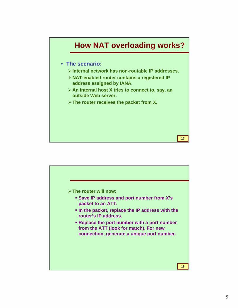
How NAT overloading works?
• The scenario:Internal network has non-routable IP addresses.NAT-enabled router contains a registered IP address assigned by IANA.An internal host X tries to connect to, say, an outside Web server.The router receives the packet from X.
18
The router will now:Save IP address and port number from X’s packet to an ATT. In the packet, replace the IP address with the router’s IP address.Replace the port number with a port number from the ATT (look for match). For new connection, generate a unique port number.

10
19
When a packet comes back.Its destination port is used to search ATT.Source IP address and port numbers can be obtained.Addresses changed accordingly.
20
The Address Translation Table (ATT) looks like:
4203.11.16.5112010.22.5.118D3203.11.16.5248010.23.10.5C2203.11.16.57510.5.17.85B1203.11.16.550010.5.17.112A
NAT port number
NAT IP address
Source port
number
Source IP address
SourceComputer

11
21
Capability Limit of a NAT
• Maximum number of concurrent translations:
Mainly determined by the size of the memory to store the ATT.Typical entry in the ATT takes about 160 bits.Memory size of 8 Mbyte will support about
8 x 1024 x 1024 x 8 / 160 = 4,19,000concurrent translations.
22
Which addresses to use inside?
• Private address classes.Set aside by IANA an non-routable.These addresses are considered unregistered.Routers discard these addresses, if used as destination.
A packet from a host with a private unregistered address can reach a registered destination host, but not the reverse.

12
23
The Private Address Classes
• Class A (one)10.0.0.0 to 10.255.255.255
• Class B (sixteen)172.16.0.0 to 172.31.255.255
• Class C (256)192.168.0.0 to 192.168.255.255
24
Main uses of NAT
• Pooling of IP addresses
• Supporting migration between network service providers
• IP masquerading
• Load balancing of servers

13
25
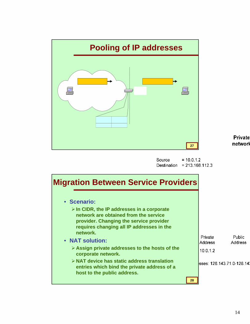
Pooling of IP addresses
• Scenario: Corporate network has many hosts but only a small number of public IP addresses
• NAT solution:Corporate network is managed with a private address space.NAT device, located at the boundary between the corporate network and the public Internet, manages a pool of public IP addresses.
26
When a host from the corporate network sends an IP datagram to a host in the public Internet, the NAT device picks a public IP address from the address pool, and binds this address to the private address of the host.
14
27
Pooling of IP addresses
28
Migration Between Service Providers
• Scenario: In CIDR, the IP addresses in a corporate network are obtained from the service provider. Changing the service provider requires changing all IP addresses in the network.
• NAT solution:Assign private addresses to the hosts of the corporate network.NAT device has static address translation entries which bind the private address of a host to the public address.

15
29
Migration to a new network service provider merely requires an update of the NAT device.
This migration is not noticeable to the hosts on the network.
Note:The difference to the use of NAT with IP address pooling is that in the present case mapping of public and private IP addresses is static.
30
Supporting Migration
H1
private address: 10.0.1.2public address: 128.143.71.21
128.195.4.120
Source = 10.0.1.2Destination = 213.168.112.3
NATdevice
PrivateAddress
PublicAddress
10.0.1.2 128.143.71.21128.195.4.120
128.143.71.21
128.195.4.120
Source = 128.143.71.21Destination = 213.168.112.3
Source = 128.195.4.120Destination = 213.168.112.3
ISP 2allocates address block
128.195.4.0/24 to privatenetw ork:
Privatenetwork
ISP 1allocates address block
128.143.71.0/24 to privatenetw ork:

16
31
IP Masquerading
• Also called: Network address and port translation (NAPT), port address translation (PAT).
• Scenario: Single public IP address is mapped to multiple hosts in a private network.
• NAT solution:Assign private addresses to the hosts of the corporate network.NAT device modifies the port numbers for outgoing traffic.
32
IP Masquerading
H1
private address: 10.0.1.2
Private network
Source = 10.0.1.2Source port = 2001
Source = 128.143.71.21Source port = 2100
NATdevice
PrivateAddress
PublicAddress
10.0.1.2/2001 128.143.71.21/2100
10.0.1.3/3020 128.143.71.21/4444
H2
private address: 10.0.1.3
Source = 10.0.1.3Source port = 3020
Internet
Source = 128.143.71.21Destination = 4444
128.143.71.21

17
33
Load Balancing of Servers
• Scenario: Balance the load on a set of identical servers, which are accessible from a single IP address.
• NAT solution:Here, the servers are assigned private addresses. NAT device acts as a proxy for requests to the server from the public network.The NAT device changes the destination IP address of arriving packets to one of the private addresses for a server.A sensible strategy for balancing the load of the servers is to assign the addresses of the servers in a round-robin fashion.
34
Load balancing of servers
Private network
Source = 213.168.12.3Destination = 128.143.71.21
NATdevice
PrivateAddress
PublicAddress
10.0.1.2 128.143.71.21
Inside network
10.0.1.4 128.143.71.21
Internet128.143.71.21
S1
S2
S3
10.0.1.4
10.0.1.3
10.0.1.2
Source= 128.195.4.120
Destination = 10.0.1.2
PublicAddress
128.195.4.120
Outside network
213.168.12.3
Source = 128.195.4.120Destination = 128.143.71.21
Source= 128.195.4.120
Destination = 10.0.1.4

18
35
Concerns about NAT
• Performance:Modifying the IP header by changing the IP address requires that NAT boxes recalculate the IP header checksum.Modifying port number requires that NAT boxes recalculate TCP checksum.
• FragmentationCare must be taken that a datagram that is fragmented before it reaches the NAT device, is not assigned a different IP address or different port numbers for each of the fragments.
36
Concerns about NAT
• End-to-end connectivity:NAT destroys universal end-to-end reachabilityof hosts on the Internet. A host in the public Internet often cannot initiate communication to a host in a private network. The problem is worse, when two hosts that are in a private network need to communicate with each other.
19
37
Concerns about NAT
• IP address in application data:Applications that carry IP addresses in the payload of the application data generally do not work across a private-public network boundary. Some NAT devices inspect the payload of widely used application layer protocols and, if an IP address is detected in the application-layer header or the application payload, translate the address according to the address translation table.
38
Other Benefits of NAT
• Use of NAT automatically creates a firewall between the internal and external networks.
NAT will only allow connections that has originated from within the internal network.An outside host cannot initiate a connection with an internal host.
• Inbound mapping requires static NAT.

20
39
Is NAT a Proxy Server?
• The answer is “NO”.NAT is transparent to both source and destination hosts. But a proxy server is not transparent.NAT is a layer 3 (network) protocol. In contrast, a proxy server works at layer 4 (transport) or higher.
40
Firewall Design

21
41
Why Firewalls?
• Firewalls are effective toprotect local systems;protect network-based security threats;provide secured and controlled access to Internet;provide restricted and controlled access from the Internet to local servers.
42
Firewall Characteristics
• Design goals:All traffic from inside to outside must pass through the firewall (physically blocking all access to the local network except via the firewall).Only authorized traffic (defined by the local security police) will be allowed to pass.The firewall itself is immune to penetration (use of trusted system with a secure operating system).

22
43
1. Packet filters.2. Application-level gateways.3. Circuit-level gateways.
Types of Firewalls
44
INTERNET PRIVATE NETWORK
Some of the attacks that can be made on packet filtering routers:• IP address spoofing• Source Routing attacks• Tiny fragment attacks
Packet Filteringrouter
Packet Filtering Router

23
45
Packet Filtering Firewall
46
Packet Filtering Router (contd.)
Applies a set of rules to each incoming IP packet and then forwards or discards the packet.
Typically based on IP addresses and port numbers.Filter packets going in both directions.The packet filter is typically set up as a list of rules based on matches to fields in the IP or TCP header.Two default policies (discard or forward).

24
47
Packet Filtering Router (contd.)
• Advantages:SimplicityTransparency to usersHigh speed
• Disadvantages:Difficulty of setting up packet filter rulesLack of authentication
48
• Also called a Proxy Server; acts as relay of applicationlevel traffic.
• It is service specific.
TELNETFTP
SMTPHTTP
Application LevelGateway
Outsideconnection
Insideconnection
OutsideHost
InsideHost
Application-Level gateway

25
49
Application Level Gatway
50
Application-level Gateway (contd.)
• Application-level GatewayAlso called proxy serverActs as a relay of application-level traffic
• Advantages:Higher security than packet filtersOnly need to scrutinize a few allowable applicationsEasy to log and audit all incoming traffic
• Disadvantages:Additional processing overhead on each connection (gateway as splice point)

26
51
• This can be a standalone system / specialized system.• It does not permit an end-to-end TCP connection; rather the gateway
sets up two TCP connections. • Once the TCP connections are established, the Gateway relays TCP
segments from one connection to the other without examining the contents.
Out
Circuit Level Gateway
Outsideconnection
Insideconnection
OutsideHost
InsideHost
Out
Out
In
In
In
Circuit-Level gateway
52
Circuit Level Gateway

27
53
Circuit-level Gateway (contd.)
Stand-alone system, or specialized function performed by an Application-level Gateway.Sets up two TCP connections:
The gateway typically relays TCP segments from one connection to the other without examining the contents.
The security function consists of determining which connections will be allowed.Typically use is a situation in which the system administrator trusts the internal users.
An example is the SOCKS package.
54
Bastion Host
• It is a system identified by the firewall administrator as a critical point in the network’s security.
It executes a secure version of its OS and is trusted.It consists of services which are essential.Requires additional authentication before access is allowed.

28
55
Firewall Configurations
• In addition to the use of simple configuration of a single system (single packet filtering router or single gateway), more complex configurations are possible
• Three common configurations are in popular use.
56
Screened Host Firewall (Single-homed host)
Internet
Private Network Hosts
Information Server
Packet filtering router
Bastion Host
Private Network Hosts

29
57
• Firewall consists of two systems:A packet-filtering routerA bastion host
• Configuration for the packet-filtering router:
Only packets from and to the bastion host are allowed to pass through the router.
• The bastion host performs authentication and proxy functions.
58
• Greater security than single configurations because of two reasons:
Implements both packet-level and application-level filtering (allowing for flexibility in defining security policy).An intruder must generally penetrate two separate systems.

30
59
Screened Host Firewall (dual-homed host)
Internet
Private Network Hosts
Information Server
Packet filtering router
Bastion Host
This configuration physically prevents security breach.
60
The packet-filtering router is not completely compromised.Traffic between the Internet and other hosts on the private network has to flow through the bastion host.

31
61
Screened Subnet Firewall
Internet
Information Server
Outside router
Bastion Host
Private Network
Modem
Inside router
62
Most secure configuration of the three.Two packet-filtering routers are used.Creation of an isolated sub-network.
• Advantages:Three levels of defense to thwart intruders.The outside router advertises only the existence of the screened subnet to the Internet (internal network is invisible to the Internet).The inside router advertises only the existence of the screened subnet to the internal network.
The systems on the inside network cannot construct direct routes to the Internet.

32
63
Distribution
6506
FoundationCORE
6509
2948 29483524
FoundationCORE
6509
FoundationCORE
6509
5500
BSNLROUTER
2Mbps Link
4000
7507ROUTER
SINGTELGATEWAY
PIX
PIX
8 Mbps Link
No Firewall here
Network Schematic at IIT Kharagpur
64
FoundationCORE
6509
FoundationCORE
6509
FoundationCORE
6509
BSNLROUTER
7507ROUTER
INTERNET
Existing L3 switch
Mail server File serverLocal
DNS server
VLAN VLAN VLAN
L3 switch
Mail Relay Web serverSMTP AVGateway
L2 switch
Security management softwares
User Zone
AV AV AV
DMZ ZoneSecurity Management Zone
Zone of Locally Accessed Servers
Restructuring of the network and solutions
New Server Zone firewall
L2 switch
L2 switch
ExistingFirewall
NewNIDS
L2 switch
Core Switches with Core IDS
New Perimeter firewall