providing rapid relief for - wordpress.com
TRANSCRIPT

1
Providing rapid relief for
‘dig up & rebuild trauma’
Since 2014
Presented by
Jason Cooper (Wollongong Council)
&Gabriel Tugrul
(GT Civil Pty Ltd)

2
There is usually quite a mess underground
By the time you
see symptoms
at the surface

3
creek and traffic remained ‘live’ during grout injection phase
This was made possible by detailed planning
beginning right back at the scoping stage

DIAGNOSISVoiding was found ‘by accident’ although symptoms had been evident for decades
Recurrent subsidence
Visual inspections from the surface did not provide any indication of the true extent of voids we later found in the embankment
CCTV had been taken in both cells and reported only minor to moderate defect scores
4

Subsidence only present over culvert
5
Probably
NOT
a
compaction problem

Sunken areas directly over culvert cells
6
Anecdotally the rate of subsidence had been slow but consistent
Asphalt filling every few years
Was looking like a fairly minor issue until we looked in the pipes..
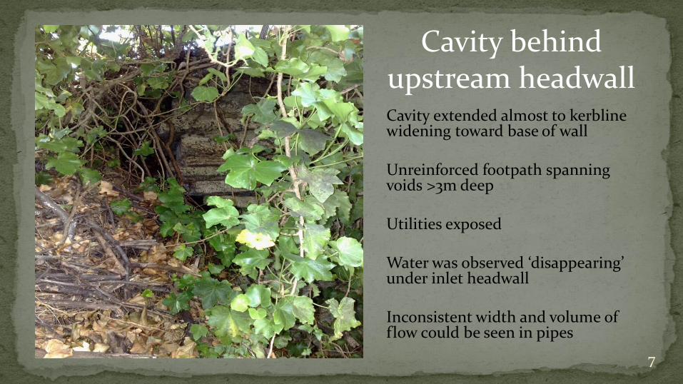
Cavity behind upstream headwall
7
Cavity extended almost to kerblinewidening toward base of wall
Unreinforced footpath spanning voids >3m deep
Utilities exposed
Water was observed ‘disappearing’ under inlet headwall
Inconsistent width and volume of flow could be seen in pipes

Visible misalignment
8
Pools formed at significant displacements
Water flowing out from underneath pipe
Erosion beneath pipe caused further displacement
Here I’m beginning to suspect the CCTV was wrong…

testing the market for ideas;
we outsourced refurbishment design
with a brief to investigate further and avoid replacement if possible
9
During design a new hole appeared behind the downstream headwall
This one definitely appeared to be related to the culvert so we engaged a confined spaces team to assess and affect repairs from in-pipe

Seen from inside the pipe the hole was clearly caused by joint displacement
Loss of fines from backfill and extensive displacement of coarser particles were observed
10
A water main had been exposed by the hole
Due to width of the twin cell installation this complicated the usual ‘sheet of tin’ approach

Expanding foam was used to temporarily seal the joint to allow concreting from above
Viscosity of foam required some tricky manoeuvres to keep it in the top of the pipe long enough to expand and cure
11

After SOME hassles… the dodgy joint was sealed all round
Observations were made of extent of voids and character of surrounding soils.
NOT good news but it did get us thinking about how to fill these voids…
12

Back up at ground level we visually confirmed the bottom of the hole was plugged…
Then capped it with concrete using EPS foam to maintain clearance to water main
Meanwhile…
13

FIRST PASS DESIGN
14
Design consultant proposed rebuilding headwalls and structural relining.
Voids were not proposed to be treated –consultant advised this was a minor problem that would sort itself out once the pipes were relined
Detailed internal inspection indicated that the voids were extensive and hydraulically connected
Some design amendments were proposed…

PROPOSED DESIGN AMENDMENTS
3.6m vertical walls to be replaced with naturally stable batters (made possible by pipe extension)
Cast in-situ components requiring complex and risky pours to be replaced with off-the-shelf precast
Demolition and disposal costs to be reduced by retaining existing structures or re-using as controlled fill
Reduce footprint and cost of energy dissipator by emulating natural process observed at this site
Take advantage of opportunity to reformat the upstream area to facilitate a future debris control device
Facilitate maintenance by providing permanent access and getting rid of gabion and reno bits
_____________________________________________________________________________________________________________________
Extensive (and expensive) reno mattress overtopping protection to be replaced with systematic revegetation based on detailed modelling of overtopping hydraulics
Spiral wound structural reline with annulus grouting is costly, does not treat embankment voids, and reduces pipe capacity. This measure can be replaced with injection grouting to realign pipes, fill voids, and refresh aged concrete by encasing weathered elements in alkaline paste rich with binder chemicals
15Does this seem like a good idea?? - It took us 2 years to decide
INNOVATION 101

REVISED DESIGN
A better fit for site and objectives but required some acceptance of risk…
16
Vertical walls replaced by batters
Batter designed to suit fill material sourced from depot stockpile
Old structures left in place or re-used
Permanent maintenance access
Training works and structural footing to suit future debris control device installation
Headwalls purpose designed to contain injected grout and prevent future bypass

17
UPSTREAM Encased pipe joints Cut off wall Porous footing
DOWNSTREAM Encased joints Porous footing Outlet basin

PLANTS AS OVERTOPPING PROTECTION – OFF TOPIC BUT INTERESTING
18
Revegetation was proposed as an alternative to reno
mattress.
Based on sound design practice this approach was ultimately accepted by the owner of the downstream
embankment (RMS)

19
BACK TO THE KNITTING – HEADWALL DETAIL
UPSTREAM DOWNSTREAM

20
OUTLET BASIN
Intended for spill control during grouting and to remain in place as
permanent energy dissipation
Shamelessly plagiarises a similar design previously deployed at this
site by ‘mother nature’
21
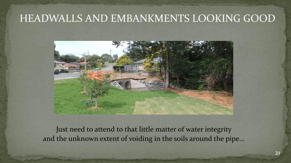
HEADWALLS AND EMBANKMENTS LOOKING GOOD
Just need to attend to that little matter of water integrity
and the unknown extent of voiding in the soils around the pipe…

INJECTION GROUTING
22
Two stage contract:
Lump sum to prep and rehabilitate
Schedule of rates for injected grout
by the litre
Refer to main paper for notes on estimating volumes and developing spec

23
STEP 1
SCOPING
Catalogued all defects where
pressurised water could get into the
pipe.
Used rodding and visual assessment to
estimate void volume
(refer main paper)

24
STEP 2
PATCHINGSeal defects considering:
what sort of pressure are we expecting?
How sound is the surrounding material?
Do we want this joint to resist deflection or to show it
for monitoring?
Each defect needs unique consideration

25
STEP 3 - INJECTION
Pumping equipment grout blend and spacing of injection /
monitoring ports all require detailed project specific
consideration.
Refer to main paper for further discussion

26
STEP 4 –
WATCH, WAIT…. THEN WAIT SOME MORE…

27
STEP 5 – GIVE YOURSELF A PAT ON THE BACK
STEP 6 – LOCK OFF AND MOVE ON

28
FIRST LIFT
very low pressure
Injection and monitoring both near invert
Pushing grout across under pipe as well as along length
Aims to create a ‘slab’ structure beneath the pipe to protect sewer crossing beneath and provide resistance for higher
pressure lifts
By far the greatest volume of grout

29
SECOND LIFT
Higher pressure
Closer port spacing
Aiming to encase sides of pipe by pushing grout along length
In some cases grout penetrated first lift and came out on
opposite side or in adjacent cell
We needed to really be on our toes with monitoring and locking off during this lift
Highest risk of bleed to creek

30
THIRD LIFT (two weeks later)
Highest pressure
Open ports at obvert quite closely spaced
Aims to surround pipe with clean pressurised grout infiltrating all soil voids
Intention to prolong asset life
Needs an iterative approach
Higher pressures will find many weaknesses in previously injected grout structures

31

32
Some pipe realignment was
achieved during the third lift
High strength render installed during
patching is crushed
Joint closure causes spalling of pipe wall
Widespread clean water ingress
indicates extensive coverage and reduced
permeability of surrounding soil

33
Clean grout bleed from redrilled obvert to confirm
full encasement
Injection port is a long way from monitoring port
(15m in this example)
All joints and defects between injection point
and bleed point are observed to weep clean water at a very slow rate
Pressure and travel indicate extensive
penetration and limited soil permeability

34
Slow and widespread ingress of clean water
Indicates pressure is high enough to force
water through the tiniest of cracks
Together with greater distance between ports gives confidence that penetrable voids are
filled
Clean nature of water indicates residual
porosity is insufficient to pass very fine solids
from grout

35
Appearance of fine cracks indicates precipitation of
binder material into defects as water is squeezed through
Working from end to middle deflection
caused by realignment shifts gradually becomes
more linear
Open joints are forced closed
dislodging previously injected grout

36
Very high pressures used in various stages
of third lift
High pressure used to confirm ‘compaction’ of grout injected into formwork over very
large repairs
Theory that initial inject fills,
subsequent injection hydraulically
fractures then fills voids with fresh grout

37
Activation of the porous footing under
headwall apron
Grouting continued until clean bleed over
full length of joint
Injected grout fills voids in porous
footing to increase strength and reduce
permeability
Also handy for confirming linear
extent of grout travel

38
Zero deaths were incurred
A single grout bleed to the basin was
observed during the second lift
Grout bleed occurred along the cold joint
between precast headwall apron and cast in-situ cut off
wall
No lifting of pond invert occurred

Estimated costs for treatment proposed by consultant Civil works - $1,040,000 Reline - $630,000 TOTAL = $1,670,000
Actual costs for treatment which was deployed Civil works (incl. reveg) $429,000 Injection grouting (incl. prep) $260,000 TOTAL $689,000
39

40

41
Observation of unusual turbulence patterns in
outflows from detention basin led to suspicion
that gabions were undermined
Review of records indicated gabions laid on working pad over scabbled hard rock –should be OK right?
Dewatered for inspection during detention basin
maintenance

42
Closer inspection revealed sound rock had been removed
Theory that hydraulic forces ‘plucked’ chunks of rock
Evidenced by loss of material along
natural jointing planes
Some similar rock found in creek bed

43
Rock fill and low permeability fabric used to make ‘formwork’
2” line mix ‘injected’ below gabions using pressure induced by attaching
landline to a hopper parked 5m above injection point
Pencil vibrators used to assist spread of grout
