proposed flight research of a dual-bell rocket nozzle ... › archive › nasa ›...
TRANSCRIPT

American Institute of Aeronautics and Astronautics
1
Proposed Flight Research of a Dual-Bell Rocket Nozzle Using the NASA F-15 Airplane
Daniel S. Jones1 and Trong T. Bui2 NASA Dryden Flight Research Center, Edwards, California, 93523
and
Joseph H. Ruf3 NASA Marshall Space Flight Center, Huntsville, Alabama, 35812
For more than a half-century, several types of altitude-compensating rocket nozzles have been proposed and analyzed, but very few have been adequately tested in a relevant flight environment. One type of altitude-compensating nozzle is the dual-bell rocket nozzle, which was first introduced into literature in 1949. Despite the performance advantages that have been predicted, both analytically and through static test data, the dual-bell nozzle has still not been adequately tested in a relevant flight environment. This paper proposes a method for conducting testing and research with a dual-bell rocket nozzle in a flight environment. We propose to leverage the existing NASA F-15 airplane and Propulsion Flight Test Fixture as the flight testbed, with the dual-bell nozzle operating during captive-carried flights, and with the nozzle subjected to a local flow field similar to that of a launch vehicle. The primary objective of this effort is not only to advance the technology readiness level of the dual-bell nozzle, but also to gain a greater understanding of the nozzle mode transitional sensitivity to local flow-field effects, and to quantify the performance benefits with this technology. The predicted performance benefits are significant, and may result in reducing the cost of delivering payloads to low-Earth orbit.
Nomenclature ACN = altitude-compensating nozzle A* = nozzle throat area CB = conventional-bell CDE = Cone Drag Experiment Cf = thrust coefficient CFD = computational fluid dynamics DFRC = Dryden Flight Research Center (Edwards, California) F = thrust IV&V = independent verification and validation lbf = pounds force LEO = low-Earth orbit MSFC = Marshall Space Flight Center (Huntsville, Alabama) NASA = National Aeronautics and Space Administration NPR = nozzle pressure ratio (PC/Pamb) NTF = Nozzle Test Facility Pamb = ambient pressure PC = nozzle chamber pressure PFTF = Propulsion Flight Test Fixture psf = pounds per square foot 1 Aerospace Engineer, Aerodynamics and Propulsion Branch, P.O. Box 273/MS 4800-2228, AIAA Senior Member. 2 Aerospace Engineer, Aerodynamics and Propulsion Branch, P.O. Box 273/MS 4840-118, AIAA Senior Member. 3 Aerospace Engineer, ER42/Fluid Dynamics Branch Combustion Analysis Team, MS 4203, AIAA Member.
https://ntrs.nasa.gov/search.jsp?R=20130014511 2020-07-18T08:18:53+00:00Z
American Institute of Aeronautics and Astronautics
2
TRL = technology readiness level USAF = United States Air Force
I. Introduction ackground on the development and performance of the conventional-bell (CB) nozzle will first be provided. This background will serve to unveil the impetus behind improving nozzle performance, a motivation that can
be traced back to national technological roadmaps. Several types of altitude-compensating nozzle (ACN) concepts have been proposed to improve nozzle performance, one of which is the dual-bell rocket nozzle. A brief background on these concepts will be provided, along with more detail on the dual-bell nozzle and the current technology readiness level (TRL) of this technology.
A. CB Nozzle Background In 1882, the Swedish engineer Carl G. P. de Laval first introduced his impulse steam turbine.1 He later
displayed a significantly improved version of his single-stage steam turbine at the 1893 World Columbian Exposition in Chicago, Illinois; a system which utilized a unique series of convergent-divergent nozzles.2 Later, in 1915, Robert H. Goddard was the first to utilize the de Laval nozzle with early rocket experiments, demonstrating a significant efficiency improvement in converting the fuel’s chemical energy into the kinetic energy of the rocket.3 Ever since this time the CB nozzle has been the gold standard for the architecture of virtually all rockets.
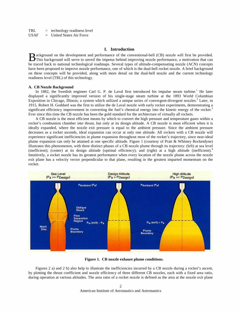
A CB nozzle is the most efficient means by which to convert the high pressure and temperature gases within a rocket’s combustion chamber into thrust, but only at its design altitude. A CB nozzle is most efficient when it is ideally expanded, where the nozzle exit pressure is equal to the ambient pressure. Since the ambient pressure decreases as a rocket ascends, ideal expansion can occur at only one altitude. All rockets with a CB nozzle will experience significant inefficiencies in plume expansion throughout most of the rocket’s trajectory, since near-ideal plume expansion can only be attained at one specific altitude. Figure 1 (courtesy of Pratt & Whitney Rocketdyne) illustrates this phenomenon, with three distinct phases of a CB nozzle plume through its trajectory: (left) at sea level (inefficient); (center) at its design altitude (optimal efficiency); and (right) at a high altitude (inefficient).4 Intuitively, a rocket nozzle has its greatest performance when every location of the nozzle plume across the nozzle exit plane has a velocity vector perpendicular to that plane, resulting in the greatest imparted momentum on the rocket.
Figure 1. CB nozzle exhaust plume conditions.
Figures 2 a) and 2 b) also help to illustrate the inefficiencies incurred by a CB nozzle during a rocket’s ascent, by plotting the thrust coefficient and nozzle efficiency of three different CB nozzles, each with a fixed area ratio, during operation at various altitudes. The area ratio of a rocket nozzle is defined as the area at the nozzle exit plane
B

American Institute of Aeronautics and Astronautics
3
divided by the area at the throat of the nozzle. From these figures, it is evident that each of the CB nozzles can achieve optimal flow conditions only at one altitude during the rocket’s ascent. Figure 2 b) reveals that each of the CB designs incur greater performance losses when operating farther from this design altitude, in either direction.
Figure 2 a). Plot of nozzle thrust coefficient versus altitude.
Figure 2 b). Plot of nozzle efficiency versus altitude.
Figure 2. Plot of nozzle performance versus altitude, with three different CB nozzles, with area ratios of 50, 70, and 100.

American Institute of Aeronautics and Astronautics
4
The thrust coefficient is used by nozzle designers to help evaluate nozzle performance. Equation (1) shows the connection between the thrust coefficient (Cf) to the rocket’s thrust (F), chamber pressure (PC), and the area at the throat of the nozzle (A*).
(1)
Figure 2 can be used in combination with Eq. (1), helping to illustrate that performance (thrust) is directly
related to the thrust coefficient, and that a CB nozzle experiences considerable performance losses throughout most of a rocket’s trajectory. Utilization of some type of ACN will enable the actual thrust coefficient to be closer to the optimized thrust coefficient, directly increasing the thrust over the rocket’s integrated trajectory. This overall increase in thrust results in a rocket with greater performance, which can deliver higher mass payloads to low-Earth orbit (LEO) for a similar launch vehicle.
Decreasing the cost of delivering payloads to LEO has been a vision for the National Aeronautics and Space Administration (NASA) and the private sector for decades, and aligns well with national interests. Most recently, this national goal has been reiterated within NASA’s integrated set of fourteen space technology roadmaps, each of which recommends the overall technology investment strategies and prioritization of NASA’s space technology activities. The first of these fourteen technology areas is the Launch Propulsion Systems Roadmap, which emphasizes that “reliable and cost-effective access to space is a fundamental capability required for all of NASA’s in-space missions.” Repeatedly within this roadmap, the desire to reduce launch costs is highlighted as a figure of merit, and several technology investment areas are proposed to achieve this overarching goal, one of which is the development of advanced nozzle concepts. This roadmap recognizes and outlines that “design, modeling, and demonstration of advanced nozzle concepts” are required milestones within the path to advance these technologies to a TRL of 6.5
Another negative consequence of a CB nozzle design is caused by opposing design requirements, between the requirement to optimize nozzle performance and the requirement to mitigate lateral structural loads. During engine start-up and shut-down transients, asymmetric detached-flow within the nozzle can occur, causing significant side loads that the engine must withstand and greater structural loads on the nozzle shell.6 The requirement to mitigate these structural loads leads to a CB nozzle design that mitigates nozzle flow overexpansion during launch, which is therefore, not optimized for nozzle performance over the rocket’s integrated trajectory.
B. ACN and Dual-Bell Nozzle Background To improve the efficiency of a rocket when it is at any other altitude than its design altitude, a type of ACN is
required, allowing the nozzle-flow pressure at the nozzle exit plane to be better matched with the ambient pressure. Several types of ACN designs have been proposed and analyzed with this goal in mind. Figure 3 shows a schematic for four of these ACN designs. Unfortunately, other than the aerospike nozzle, only minimal advances in the TRL of these designs have been achieved since their conception. Several full scale aerospike engines have been ground tested, and to our knowledge, only the aerospike nozzle has been tested in a relevant flight environment; during the NASA Dryden Flight Research Center (DFRC) (Edwards, California) aerospike nozzle flight research effort.7 The goal of the current effort is to advance the TRL of the dual-bell rocket nozzle through flight research.

American Institute of Aeronautics and Astronautics
5
Figure 3. Examples of ACN designs.
A dual-bell nozzle has a distinct shape of two overlapped bells, introducing a geometric inflection point along
the nozzle’s inner contour. Figure 4 shows two views of a dual-bell nozzle. The inflection point in the contour presents a discontinuity in the nozzle plume flow field along the nozzle wall, facilitating a more symmetric and predictable nozzle flow field during engine transients at launch. In addition, the dual-bell nozzle is also expected to achieve a higher performance over a CB nozzle at lower altitudes (with higher ambient pressures), since the plume will not be significantly over-expanded, and it will be better matched to the ambient pressure. At higher altitudes (with lower ambient pressures), the dual-bell nozzle takes advantage of utilizing the second bell, expanding the plume further. Once again, the plume is allowed to be better matched to the ambient pressure, now at higher altitudes. Figures 5 and 6 show computational fluid dynamics (CFD) analysis conducted by the NASA Marshall Space Flight Center (MSFC) (Huntsville, Alabama), with the dual-bell nozzle operating with different back pressures (both figures showing nozzle flow into a quiescent environment). When considering a rocket’s performance over its entire trajectory, the dual-bell nozzle has been predicted to achieve a higher integrated nozzle performance efficiency, which is expected to result in a greater capability of payload mass to LEO.
Figure 4. Front view and isometric view of a typical dual-bell nozzle.

American Institute of Aeronautics and Astronautics
6
Figure 5. Mach contours from a CFD analysis for the dual-bell nozzle at low altitude, with nozzle flow into a quiescent environment.
Figure 6. Mach contours from a CFD analysis for the dual-bell nozzle at high altitude, with nozzle flow into a quiescent environment.
In 1949, the dual-bell nozzle first appeared in literature within a study by the Jet Propulsion Laboratory (Pasadena, California).8 At the time, this conceptual rocket nozzle shape was believed to offer performance advantages over the CB nozzle. Since that time, several organizations around the world have studied the dual-bell
Low Altitude Mode, ‘Mode 1’
High Altitude Mode, ‘Mode 2’

American Institute of Aeronautics and Astronautics
7
nozzle analytically, and echoed the belief that this nozzle promises greater performance. Considering the performance advantages suggested, the TRL of the dual-bell nozzle has not made the advancements expected. The first static-test experiments published, over four decades after the dual-bell nozzle was first conceived, were conducted by the Rocketdyne Division of Rockwell International (now Pratt & Whitney Rocketdyne, Canoga Park, California) with cold-flow through the nozzle.9 Since then, analytical studies of dual-bell nozzles have continued but only a few organizations around the world have complemented their analytical effort with static test data to verify their performance predictions. Of these few static tests, to date, most have been conducted with non-reacting flow exhausting through the nozzle into a quiescent and non-transient environment. Very few organizations have conducted dual-bell nozzle testing with reacting flow. To the authors’ knowledge, no organization has tested the dual-bell nozzle in a relevant flight environment, and it is our opinion that dual-bell nozzle technology is approximately at a NASA TRL of 3 (where a TRL of 9 corresponds to a flight-proven technology, through successful mission operations).10
NASA MSFC is one of the organizations that have complemented their analytical efforts on the dual-bell nozzle with static tests. MSFC conducted static testing with the dual-bell nozzle in the MSFC Nozzle Test Facility (NTF), utilizing a non-reacting flow while varying the nozzle pressure ratio (NPR). During this research, the performance of the dual-bell nozzle was also quantitatively compared to a similar CB nozzle. This testing and research helped verify the prediction that the dual-bell nozzle had a greater nozzle efficiency and thrust than the comparable CB nozzle at several NPR conditions, particularly at the lower NPR conditions. Figure 7 shows a photo of the test setup at the MSFC NTF with a dual-bell nozzle. Figure 8 shows a photo with the comparable CB nozzle at the NTF. As can be seen in these figures, both tests included pressure ports along the nozzle wall to measure how the flow responds to varying NPR.
Figure 7. Dual-bell nozzle during testing at the NASA MSFC NTF.
American Institute of Aeronautics and Astronautics
8
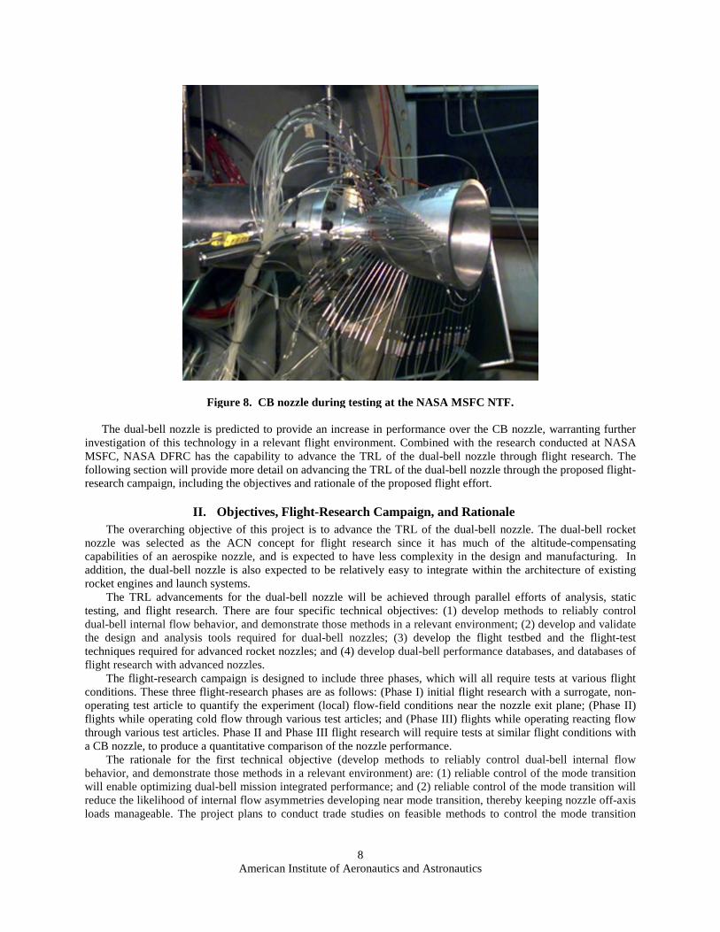
Figure 8. CB nozzle during testing at the NASA MSFC NTF. The dual-bell nozzle is predicted to provide an increase in performance over the CB nozzle, warranting further investigation of this technology in a relevant flight environment. Combined with the research conducted at NASA MSFC, NASA DFRC has the capability to advance the TRL of the dual-bell nozzle through flight research. The following section will provide more detail on advancing the TRL of the dual-bell nozzle through the proposed flight-research campaign, including the objectives and rationale of the proposed flight effort.
II. Objectives, Flight-Research Campaign, and Rationale The overarching objective of this project is to advance the TRL of the dual-bell nozzle. The dual-bell rocket
nozzle was selected as the ACN concept for flight research since it has much of the altitude-compensating capabilities of an aerospike nozzle, and is expected to have less complexity in the design and manufacturing. In addition, the dual-bell nozzle is also expected to be relatively easy to integrate within the architecture of existing rocket engines and launch systems.
The TRL advancements for the dual-bell nozzle will be achieved through parallel efforts of analysis, static testing, and flight research. There are four specific technical objectives: (1) develop methods to reliably control dual-bell internal flow behavior, and demonstrate those methods in a relevant environment; (2) develop and validate the design and analysis tools required for dual-bell nozzles; (3) develop the flight testbed and the flight-test techniques required for advanced rocket nozzles; and (4) develop dual-bell performance databases, and databases of flight research with advanced nozzles.
The flight-research campaign is designed to include three phases, which will all require tests at various flight conditions. These three flight-research phases are as follows: (Phase I) initial flight research with a surrogate, non-operating test article to quantify the experiment (local) flow-field conditions near the nozzle exit plane; (Phase II) flights while operating cold flow through various test articles; and (Phase III) flights while operating reacting flow through various test articles. Phase II and Phase III flight research will require tests at similar flight conditions with a CB nozzle, to produce a quantitative comparison of the nozzle performance.
The rationale for the first technical objective (develop methods to reliably control dual-bell internal flow behavior, and demonstrate those methods in a relevant environment) are: (1) reliable control of the mode transition will enable optimizing dual-bell mission integrated performance; and (2) reliable control of the mode transition will reduce the likelihood of internal flow asymmetries developing near mode transition, thereby keeping nozzle off-axis loads manageable. The project plans to conduct trade studies on feasible methods to control the mode transition

American Institute of Aeronautics and Astronautics
9
within the dual-bell nozzle during flight. One or more of the leading methods will be incorporated into the design of the system, and then demonstrated in flight.
The rationale behind the second technical objective (to develop and validate the design and analysis tools required for dual-bell nozzles) is focused on improving the current designs of the dual-bell nozzle, as well as improving our understanding of dual-bell nozzle flow behavior. Design and analysis of dual-bell nozzles is relatively immature, and a greater number of ground and flight tests will enable improvement and validation of the existing analytical tools.
The rationale behind the third technical objective (to develop the flight testbed and the flight-test techniques required for advanced rocket nozzles) is focused on improving the current capabilities at DFRC to support development of advanced rocket nozzles. It is the authors’ opinion that the potential payoff of ACN technology warrants investment, and expanding on DFRC’s current flight testbed capabilities will facilitate the rapid flight research of other advanced rocket nozzles, even beyond the dual-bell rocket nozzle.
The rationale behind the fourth technical objective (to develop dual-bell performance databases, and databases of flight research with advanced nozzles) is similar to the rationale behind the second technical objective. Static ground test and flight research data for ACN designs are either rare or nonexistent, hence the need to conduct the current research and expand on the existing nozzle performance database. As noted earlier, most of the static tests that have been completed have been conducted with non-reacting flow into a quiescent environment. In many publications, the limitations of the static test data were often followed by the researcher’s admission that the dual-bell nozzle flow field and performance should be investigated in a relevant flight environment, to better understand the performance gains that are possible.
Finally, the rationale behind conducting each of the three phases of the flight-research campaign will be highlighted here, in order of an increasing level of TRL and system complexity. The rationale behind Phase I is to fully understand the local flow-field conditions prior to obtaining data with an operating nozzle, since the nozzle flow behavior is predicted to be highly dependent on the external flow field. Rationale behind Phase II of the flight-research campaign is two-fold: (1) to allow existing cold-flow data from MSFC testing to be leveraged as much as possible, and compared against flight-research data; and (2) to permit an intermediate or build-up approach in system complexity (prior to reacting flow), for risk mitigation purposes. The rationale behind Phase III of the flight-research campaign is obvious; that operating a dual-bell rocket nozzle with reacting flow into a high velocity flow field will be the most relevant flight-test environment possible, enabling the TRL to be advanced.
III. The F-15/PFTF Flight Testbed Capability The dual-bell rocket nozzle should be flight-tested in a relevant flight environment prior to integration and
utilization within the space launch architectures of tomorrow. With a focus on flight testing and research, NASA DFRC has a unique capability with its fleet of F-15 airplanes, as well as with the Propulsion Flight Test Fixture (PFTF). This section will provide an overview of the F-15/PFTF, and top-level details on the nozzle placement and sizing criteria. The F-15/PFTF limitations will also be detailed, including the PFTF internal capacity available, PFTF in-flight thrust limitations, and the F-15/PFTF flight envelope.
A. Overview of the NASA F-15/PFTF NASA DFRC has a long history of rocket propulsion flight research, including an equally significant
background in captive carry flight research. This expertise has been utilized since the 1940s to help advance the TRL of several types of systems, allowing a more detailed inspection of physical phenomenon in a relevant flight environment. When conducted in concert with analytical efforts and ground testing, the ability to conduct captive carry flight research almost always proves valuable, and can often be used for independent verification and validation (IV&V) of pre-existing data.
Among DFRC’s fleet of airplanes is the F-15B airplane and three F-15D airplanes. The F-15B airplane was acquired in 1993 from the Hawaii Air National Guard, and then converted into a research testbed airplane. DFRC’s three F-15D airplanes were acquired in 2010 from the United States Air Force (USAF) Tyndall Air Force Base (Florida), and are being converted from their role as air-superiority fighters into future flight research and operational support aircraft at DFRC. Figure 9 shows a photo of the NASA DFRC F-15B airplane.11 Figure 10 shows a photo of the NASA DFRC F-15D airplanes.12

American Institute of Aeronautics and Astronautics
10
Figure 9. The NASA DFRC F-15B airplane in flight.
Figure 10. The NASA DFRC F-15D airplanes, during arrival from the USAF.
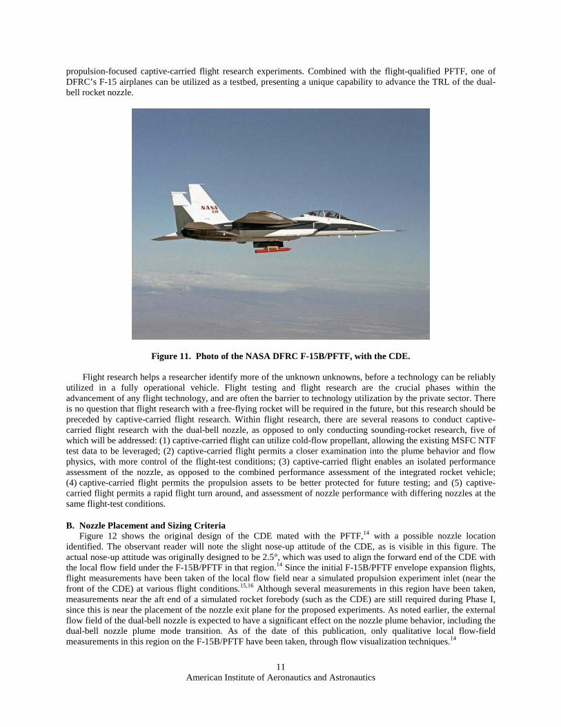
DFRC’s expertise with captive-carried flight research led to the creation of the PFTF. DFRC led the design and development of the PFTF, and then integrated the PFTF with the centerline pylon of the F-15B airplane. The F-15B/PFTF initial expansion flights were completed in 2001 and 2002. Figure 11 shows a photo of the PFTF mated with the F-15B airplane, with the Cone Drag Experiment (CDE).13 The CDE was mated underneath the PFTF, and was utilized in the envelope expansion flights to spatially and inertially simulate a large propulsion test experiment that could be carried by the PFTF.14 Since these initial flights, the F-15B/PFTF has been utilized for a variety of
American Institute of Aeronautics and Astronautics
11
propulsion-focused captive-carried flight research experiments. Combined with the flight-qualified PFTF, one of DFRC’s F-15 airplanes can be utilized as a testbed, presenting a unique capability to advance the TRL of the dual-bell rocket nozzle.
Figure 11. Photo of the NASA DFRC F-15B/PFTF, with the CDE. Flight research helps a researcher identify more of the unknown unknowns, before a technology can be reliably
utilized in a fully operational vehicle. Flight testing and flight research are the crucial phases within the advancement of any flight technology, and are often the barrier to technology utilization by the private sector. There is no question that flight research with a free-flying rocket will be required in the future, but this research should be preceded by captive-carried flight research. Within flight research, there are several reasons to conduct captive-carried flight research with the dual-bell nozzle, as opposed to only conducting sounding-rocket research, five of which will be addressed: (1) captive-carried flight can utilize cold-flow propellant, allowing the existing MSFC NTF test data to be leveraged; (2) captive-carried flight permits a closer examination into the plume behavior and flow physics, with more control of the flight-test conditions; (3) captive-carried flight enables an isolated performance assessment of the nozzle, as opposed to the combined performance assessment of the integrated rocket vehicle; (4) captive-carried flight permits the propulsion assets to be better protected for future testing; and (5) captive-carried flight permits a rapid flight turn around, and assessment of nozzle performance with differing nozzles at the same flight-test conditions.
B. Nozzle Placement and Sizing Criteria Figure 12 shows the original design of the CDE mated with the PFTF,14 with a possible nozzle location identified. The observant reader will note the slight nose-up attitude of the CDE, as is visible in this figure. The actual nose-up attitude was originally designed to be 2.5°, which was used to align the forward end of the CDE with the local flow field under the F-15B/PFTF in that region.14 Since the initial F-15B/PFTF envelope expansion flights, flight measurements have been taken of the local flow field near a simulated propulsion experiment inlet (near the front of the CDE) at various flight conditions.15,16 Although several measurements in this region have been taken, measurements near the aft end of a simulated rocket forebody (such as the CDE) are still required during Phase I, since this is near the placement of the nozzle exit plane for the proposed experiments. As noted earlier, the external flow field of the dual-bell nozzle is expected to have a significant effect on the nozzle plume behavior, including the dual-bell nozzle plume mode transition. As of the date of this publication, only qualitative local flow-field measurements in this region on the F-15B/PFTF have been taken, through flow visualization techniques.14

American Institute of Aeronautics and Astronautics
12
Figure 12. Design of the CDE mated with the PFTF.
C. PFTF Internal Capacity The PFTF has an internal capacity that can be used for the dual-bell rocket nozzle propellant feed system. Figure 13 shows an expanded view of the PFTF, with the PFTF main structure, experiment racks, and force balance.17 The PFTF main structure was fabricated from a solid billet of 6061-T6 aluminum, with an overall length of 107 inches, an overall height of 19 inches, and an overall width of 10 inches. The PFTF main structure is divided into three bays (forward, mid, and aft), that are separated by bulkheads and the force-balance system. The forward rack, mid rack, and aft rack were designed for installation into these three bays, and are designed to contain components such as propellant tanks, control valves, propellant feed system plumbing, and instrumentation.17
Figure 13. Expanded view of the PFTF, with the PFTF main structure, experiment racks, and force balance.

American Institute of Aeronautics and Astronautics
13
D. PFTF Thrust Limitations The PFTF includes a force balance system, with a six-degree-of-freedom in-flight force measurement capability. Figure 13 shows an expanded view of the PFTF, with the force balance system which is located in the mid-bay.17 The maximum design loads are noted in Table 1, along with the original predicted accuracy. The system was designed to meet ultimate loads of three times the maximum design loads for each of the six component cases noted.17
Table 1. PFTF force balance specifications.
Component Design Predicted accuracy
(percent error of measured value)
Axial force ±2,000 lbf < 0.5
Side force ±500 lbf < 1.0
Vertical force ±1,500 lbf < 2.0
Roll moment ±8,520 in-lbf < 5.0
Yaw moment ±10,080 in-lbf < 5.0
Pitch moment ±55,080 in-lbf < 5.0
The force balance was utilized to take measurements of the aerodynamic and inertial forces, and the moments generated by the CDE. Data from these early flights have shown the PFTF force balance system to have repeatable axial force measurements at various flight conditions.14 The PFTF force balance system was also designed with an isolation capability, where the system could be protected with lock-out pins in the case where an in-flight measurement capability is not required.17
E. PFTF Flight Envelope The PFTF flight envelope is bounded by the F-15 free-stream altitude limit of 60,000 ft, the Mach limit of 2.0, and the dynamic pressure limit of 1,100 psf. This flight envelope is conservative, since the PFTF was designed to withstand much higher aerodynamic loads in flight.17 Although the PFTF is capable of flights up to 60,000 ft, flights higher than 50,000 ft with the F-15 airplane will require additional life support systems. Figure 14 shows the PFTF flight envelope,16 which is a subset of the F-15 flight envelope. This flight envelope provides an ample range capability in which to test the dual-bell nozzle in a relevant flight environment at numerous flight-test conditions of interest. Preliminary thoughts on flight research within this flight envelope are discussed in the following paragraphs.

American Institute of Aeronautics and Astronautics
14
Figure 14. PFTF flight envelope. Phase II of the flight-research campaign will be to operate a dual-bell nozzle with cold flow at various test conditions. Key flight test points will be complemented with cold-flow operation of a CB nozzle to enable a quantitative comparison of nozzle performance. For the dual-bell nozzle, two key altitudes will be identified: (1) a lower altitude flight for nozzle plume expansion that is optimally expanded in the first bell; and (2) a higher altitude flight for nozzle plume expansion that is optimally expanded out to the end of the second bell, at the nozzle exit plane. The high altitude flights are envisioned to be at a relatively high altitude within the F-15/PFTF range capability, since increasing altitude will enable lower test article combustion chamber pressures to be utilized (due to the lower ambient pressure). Also, Phase II flight research is envisioned to require several tests within the F-15/PFTF altitude range capability, since tests at various altitudes between the two ideal altitudes (noted above) will facilitate a better understanding of nozzle flow behavior and performance as a function of NPR. Flights between these two ideal altitudes will facilitate detailed measurements of the dual-bell flow mode transition. Phase III of the flight-research campaign will also require several tests at various altitudes of interest, as noted for Phase II. In addition to these altitude-range tests, Phase III of the flight-research campaign will likely require testing with reacting flow up to the dynamic-pressure limit of the F-15/PFTF envelope. These tests will be beneficial along this boundary of the envelope since research conducted at these test points will be closer to a relevant flight environment of a free-flying rocket. Nozzle operation may also be conducted for a prolonged duration while the F-15 airplane is rapidly climbing in altitude along the high dynamic pressure boundary, simulating a rocket’s trajectory. Phase I of the flight-research campaign will be to conduct a local flow field survey of the flight-test conditions envisioned during Phase II and Phase III. Once all of the appropriate flight-test conditions for Phase II and Phase III have been identified, these conditions will form the basis for flight activity within Phase I.
IV. Conclusion Although the dual-bell rocket nozzle is predicted to have greater performance over the CB rocket nozzle, the
dual-bell nozzle has still not been tested in a relevant flight environment. If the predictions are accurate, this performance advantage would be a valuable benefit for the architecture of future launch systems, resulting in a cost reduction of delivering payloads to LEO.
NASA DFRC and NASA MSFC have formed a collaborative effort to advance the TRL of ACN concepts, starting with the dual-bell rocket nozzle. This paper provides highlights of a proposed effort to conduct testing and research with a dual-bell rocket nozzle in a relevant flight environment. The NASA F-15/PFTF is offered as the

American Institute of Aeronautics and Astronautics
15
flight testbed, an asset that was specifically developed and flight-proven for the purpose of advancing propulsion-focused technologies through captive-carried flight research. Results from this proposed flight research effort provide evidence that the F-15/PFTF will be an excellent testbed for advancing the TRL of the dual-bell nozzle. The DFRC and MSFC collaboration will leverage the capabilities and expertise of two NASA Centers that have focused on ACN technologies, and combine their resources to contribute to a better space-launch capability for the nation.
References 1Smil, V., Creating the Twentieth Century: Technical Innovations of 1867 to 1914 and their Lasting Impact, Oxford
University Press, Inc., New York, 2005. 2Anderson, J. D., Modern Compressible Flow, with Historical Perspective, 3rd ed., McGraw-Hill, New York, 2003. 3NASA Goddard Space Flight Center, Robert Goddard and His Rockets, URL: http://www-istp.gsfc.nasa.gov/stargaze/
Sgoddard.htm [cited 3 June 2013]. 4O’Leary, R. A., and Beck, J. E., Threshold: Pratt & Whitney Rocketdyne’s Engineering Journal of Power Technology –
Nozzle Design, Pratt & Whitney Rocketdyne, URL: http://www.pwrengineering.com/articles/nozzledesign.htm [cited 3 June 2013].
5McConnaughey, P. K., Femminineo, M. G., Koelfgen, S. J., Lepsch, R. A., Ryan, R. M., and Taylor, S. A., “Launch Propulsion Systems Roadmap: Technology Area 01,” National Aeronautics and Space Administration, URL: http://www.nasa.gov/pdf/500393main_TA01-ID_rev6-NRC-wTASR.pdf [cited 5 June 2013].
6Ruf, J. H., McDaniels, D. M., and Brown, A. M., “Nozzle Side Load Testing and Analysis at Marshall Space Flight Center,” AIAA 2009-4856, 2009.
7Bui, T. T., Murray, J. E., Rogers, C. E., Bartel, S., Cesaroni, A., and Dennett, M., “Flight Research of an Aerospike Nozzle Using High Power Solid Rockets,” AIAA 2005-3797, 2005.
8Foster, C. R., and Cowles, F. B., “Experimental Study of Gas-Flow Separation in Overexpanded Exhaust Nozzles for Rocket Motors,” Jet Propulsion Laboratory, Progress Report No. 4-103, May 1949.
9Horn, M., and Fisher, S., “Dual-Bell Altitude Compensating Nozzles,” Rocketdyne Division, Rockwell International, Pennsylvania State University, Propulsion Engineering Research Center, Annual Report, Vol. II, November, 1993, pp. 140-147.
10Mankins, J. C., “Technology Readiness Levels,” National Aeronautics and Space Administration, URL: http://www.hq.nasa.gov/office/codeq/trl/trl.pdf [cited 6 June 2013].
11NASA Dryden Flight Research Center, F-15B, EC96-43546-01, URL: http://www.nasa.gov/centers/dryden/multimedia/ imagegallery/F-15B/index.html [cited 5 June 2013].
12NASA Dryden Flight Research Center, F-15D, ED10-0283-10, URL: http://www.nasa.gov/centers/dryden/multimedia/ imagegallery/F-15D/index.html [cited 5 June 2013].
13NASA Dryden Flight Research Center, F-15B, EC01-0324-3, URL: http://www.nasa.gov/centers/dryden/multimedia/ imagegallery/F-15B/index.html [cited 5 June 2013].
14Palumbo, N., Moes, T., and Vachon, M. J., “Initial Flight Tests of the NASA F-15B Propulsion Flight Test Fixture,” AIAA 2002-4131, 2002.
15Vachon, M. J., Moes, T. R., and Corda, S., “Local Flow Conditions for Propulsion Experiments on the NASA F-15B Propulsion Flight Test Fixture,” NASA/TM-2005-213670, 2005.
16Frederick, M. A., and Ratnayake, N. A., “Flight Test Results from the Rake Airflow Gage Experiment on the F-15B Airplane,” AIAA 2010-4573, 2010.
17Corda, S., Vachon, M., Palumbo, N., Diebler, C., Tseng, T., Ginn, A., and Richwine, D., “The F-15B Propulsion Flight Test Fixture: A New Flight Facility for Propulsion Research,” AIAA 2001-3303, 2001.