proposal of conversion the tugboat engines to diesel – lng
TRANSCRIPT

129
INTRODUCTION
Natural gas is used to drive vehicles in ship-ping (LNG tankers, ferries, sightseeing boats) or in rail transport (LNG shunting locomotives). It is rarely employed in air transport. It is also of-ten used in enclosed spaces such as warehouses (forklifts), ice hockey stadiums, and golf courses. The safe use of liquid natural gas is linked to the requirement for an appropriate hazard assess-ment, also required by the EU regulations, based on the knowledge of the chemical and physical
properties of the fuel [1]. Liquid natural gas in the liquid state is neither explosive nor flammable, as opposed to natural gas in the gaseous state. The knowledge of its thermodynamic properties and its phase transition behaviour is important for its safe use. In order to ignite natural gas, LNG must first be converted into a gaseous state and mixed with air at a concentration within the explosion limits and be in contact with the source of initia-tion of the necessary energy. In the event of leak-age, the liquid LNG is heated by the heat from the surroundings and becomes gaseous. The amount
Proposal of Conversion the Tugboat Engines to Diesel – LNG Operation
Martin Jurkovic1*, Tomas Kalina1, Lubomir Jancosek2, Robert Kadnar3, Piotr Gorzelanczyk4, Karel Jerabek5
1 Faculty of Operation and Economics of Transport and Communication, University of Zilina, Univerzitna 1, 010 26 Zilina, Slovakia
2 ENGUL, s.r.o., Robotnicka 14/9856, 036 01 Martin, Slovakia 3 Danube LNG, EEIG, Pristavna 10, 821 01 Bratislava, Slovakia4 Stanislaw Staszic University of Applied Sciences in Pila, Polytechnic Institute, ul. Podchorążych 10, 64-920 Piła,
Poland5 Department of Transport and Logistics, Faculty of Technology, Institute of Technology and Business in Ceske
Budejovice, Czech Republic * Corresponding author’s e-mail: [email protected]
ABSTRACTInternational shipping is the source of around 3% of global CO2 emissions. Liquefied natural gas (LNG) is cur-rently considered the only reasonable and commercially advanced alternative to the petroleum-based ship fuels. Liquefied natural gas can make a significant contribution to the diversification of transport fuels, reducing the greenhouse gas emissions from ships and heavy vehicles. The introduction of LNG technology as a drive for inland ships is a complex process. It requires activities in various areas, including development, legislation, building in-frastructure, construction of new ships or their reconstruction. The greatest problem now seems to be the certainty of investing in the new fleet or their reconstruction. It is therefore desirable to assure shipowners that the invest-ment in renewing or reconstruction should be guaranteed. This paper provides a study of reconstruction of the inland tugboat (tug) to a dual fuel system (diesel – LNG). A tugboat used by Slovak shipping company was chosen as a model vessel. The results presented a comprehensive design of the main and auxiliary engine remodelling, as well as the design of the vessel’s tanks and show how the conversion affects the basic navigational characteristics of the tugboat. Finally, the results point to the conversion methodology which is partly applicable to another type of inland tug, considering the individual specificities.
Keywords: LNG, tugboat, vessel, diesel engine, alternative fuel, regulation
Volume 13, Issue 4, December 2019, pages 129–142https://doi.org/10.12913/22998624/113424
Advances in Science and Technology Research Journal
Received: 2019.09.13Revised: 2019.10.22
Accepted: 2019.11.15Available online: 2019.12.01

Advances in Science and Technology Research Journal Vol. 13(4), 2019
130
of vapor is directly related to the amount of LNG released, the rate of leakage and the size of the crack through which LNG escapes [2]. Natural gas is a clean-burning fuel that is characterized by soot-free combustion when used in internal combustion engines. The high-octane properties of natural gas promote its use in the spark-ignited engines rather than the diesel engines [2–4]. Liq-uefied natural gas consists of a mixture of meth-ane (87 to 99 % by volume) and smaller amounts of other gases, such as ethane, propane, nitrogen. Other minor components included in the mixture would depend on the origin of natural gas. The content of sulphur compounds is very low, reach-ing about 4 ppm by weight, which contributes to the environmental acceptability of its combus-tion products. The boiling point is usually in the range of -166 °C to -157°C at atmospheric pres-sure. Liquefied natural gas has a volume that is approximately 600 times lesser than the same amount of substance in the gaseous state, which is the greatest advantage in its transport. In stor-age or transport tanks, it is usually maintained at the boiling point using a combination of elevated pressure (8–12 bar) and reduced temperature [5]. Transport represents almost a quarter of the Eu-rope’s greenhouse gas (GHG) emissions. Within this sector, shipping is responsible for about 13% of EU’s GHG emissions and of 2.2% of global GHG emissions, as reported by European Envi-ronment Agency [6] and by the third International Maritime Organization (IMO) GHG study [5]. By using LNG as a fuel in transport, the greenhouse gas emissions could be reduced by 142 million tonnes by 2040. By this year, 6,000 LNG fuelled large ships will be in operation worldwide and 480 000 LNG trucks will be in the EU.
The European Union, in cooperation with in-ternational organizations, is making a major effort to reduce emissions and increase the energy effi-ciency. This is an effort to move from the conven-tional diesel fuels to natural gas and renewable en-ergy sources [8–10]. In order to achieve this goal, IMO has recently revised Annex VI of MARPOL convention [11] introducing tight emission limits for SOx, NOx and particulate matter (PM). The requirements for the sulphur content of fuels and emissions abatement technologies installed on sea-going vessels were also introduced. Similar condi-tions are expected for the inland waterway vessels.
The first European legislation on emission limits for inland waterway vessels appeared in 2004. Directive 2004/26/EC amended Directive
97/68/EC while regulating the emissions of new engines installed on inland waterway vessels by the end of 2008. The reaction to developments in road transport has brought further adjust-ments in the form of Directives 2010/26/EU and 2012/46/EU, focusing mainly on the NOx emis-sions [12]. The latest legislation adopted by the European Parliament tightens the emission lim-its of internal combustion engines of non-road mobile machinery and thus the inland waterway vessels [13]. These measures are accompanied by more extensive support for the research on alternative fuels. Inland waterway transport has the potential to operate diesel-LNG dual-fuel sys-tems. The wider application of this fuel in trans-port is preceded by the need to build adequate infrastructure and the associated logistics [14]. It is also important to know the physical character-istics of LNG related to the long-distance trans-port. The current legislation on the transport of dangerous goods (ADN) allows the LNG tankers equipped with special cryogenic tanks to be used for the inland waterway LNG transport. Similar tanks can also be used for long-term storage at terminals. Although this technology is not new, there is little experience with its application in inland vessels. When designing and locating tanks for existing vessels, compromises must be sought, considering both the shape of the tank and the quantity of gas stored, as well as the insulation and strength properties [15].
In Slovakia, the largest inland port operator is SPaP (Slovak Shipping and Port), a. s. Like most other operators on the Danube River, the SPaP fleet has more than 30 years of experience. Sev-eral vessels have been modernized recently. In all cases, standard diesel engines have been installed.
There are two ways to switch to LNG for the existing riverboat fleets, i.e. converting the exist-ing engines to dual fuel systems or re-motorising them. This paper presents a comprehensive de-sign of the conversion of the existing engines of TR Muflon tugboat (tug).
METHODOLOGY AND GENERAL RULES FOR THE RECONSTRUCTION
The decision of the Maritime Safety Com-mittee (MSC).285 (86) adopted on 1st June 2009 applies as a temporary safety guideline for the in-stallation of natural gas-fuelled engines on ships.

131
Advances in Science and Technology Research Journal Vol. 13(4), 2019
This guidance can be adopted also for the inland navigation vessels.
The general conditions for rebuilding vessels are acceptable almost in entirety. The outlets from the pressure relief valves should normally be lo-cated at least B/3 or 6 m, whichever is greater, above the open deck and 6 m above the working area and bridges, where B is the greatest moulded breadth of the ship in metres. The outlets should normally be located at least 10 m from the nearest: • air intake, air outlet or opening to residential,
service or control areas or other gas safe areas, • an exhaust outlet from the machinery or from
the furnace equipment.
In order to comply with the underpass height of the vessel, it is very difficult to respect the con-ditions of this paragraph. Either there will be an exemption for inland waterways to the rules of placement of the outlets, or a folding outlet solu-tion will be implemented [20].
PROPOSED VESSEL FOR RECONSTRUCTION
The Muflon 1100 tug was built in the Wro-claw shipyard in Poland under the supervision of the PRS (Polish estate register). Fully-welded ship hull is divided by watertight bulkheads into four spaces, including collision spaces. The bot-tom and sides of the vessel have a transverse and deck longitudinal reinforcement system. The rib pitch is 500 mm. Frames are every third rib. The superstructure is welded, the residential part is elastic, and the other spaces are fixed. The wheel-house is welded and hydraulic foldable. The drive unit consists of two main non-reversible
motors of the type MAN D2842 LE 412 with Reintjes WAF 350 reversing gearboxes and flex-ible couplings. The propulsion is provided by two separate shaft guides and two 5-sheet propellers θ 1300 mm set in a fixed nozzle. • Main engine power: 1176 kW; • Main motors: 2 x MAN D2842 LE 412
2 x 588 kW at 1800 rpm; • Mensural diesel consumption at 100 % load:
205 g/kWh; • Subsidiary motors: 2 x Deutz BF4M 2012C; • Mensural diesel consumption at 100 % load:
243 g/kWh; • Real average diesel consumption: 90 – 140 l/h; • Diesel reserve: 16.8 t (20 000 l); • Max. navigation independence: 140 h;
A more detailed specification of the TR Mu-flon tug is solved in Proposal for the conversion of vessels to the LNG fuel system [21].
CONSTRUCTION AND OPERATION CHARACTERISTICS OF LNG TANKS
The location of additional tanks in tugs is con-siderably limited. This is due to the design of the tugs, their contour passage and their own design (pusher tug without spaces for other uses). The requirement for voyage independence was set by tug TR Muflon according to the design possibili-ties as long as possible. Cryogenic reservoirs, due to the operating pressures (up to about 1 MPa) and suitable insulation, cannot be designed in any shape, so that their shape is best met by a ball-shaped tank or a single cylindrical vessel, prefer-ably as large as possible. The hull spaces, part of which are currently diesel fuel tanks, are either
Figure 1. TR Muflon Tug
Advances in Science and Technology Research Journal Vol. 13(4), 2019
132
insignificant in volume or unsatisfactory in shape. The fundamental adjustment of the hull, in this case, would practically be the construction of a new vessel. The deck space appears to be the most suitable space to accommodate the tanks.
The detailed design for arrangement of the cryogenic technology and fuel supply and deter-mining the size of tanks solve “Proposal for the conversion of vessels to the LNG fuel system” [21] and “Technical study for engine replacement and converting the existing power drive units of tugboats to dual diesel/LNG fuel system” [22].
A vacuum space of at least 200 mm is pro-vided between the inner and outer shells to provide thermal insulation. This is intended to prevent the heating of the inner container shell. The basic requirement for the safety of cryo-genic gas storage, such as LNG, is to prevent the liquid from overheating. The heating of the liquid may eventually cause an increase in the temperature above the boiling point, resulting in liquid evaporation. Since the penetration of heat to the inner shell of the container cannot be completely prevented, evaporation of a certain limited amount of LNG, on average 0.2% of liq-uid per day, is ensured. Since evaporation is an unstoppable process, the reservoirs are protected against over-pressure by safety valves. The LNG distribution is routed on board to the pressure regulator (3 Bar-0.1 Bar), which is separated from the machine room by a safety barrier – the wall of the station. The LNG distribution up to the bulkhead is double-walled for safety rea-sons in case of leakage. The inert nitrogen gas is between the outer and inner shell. From the
pressure regulator, the pipe is routed behind the partition to the machine room to 2 main and 2 auxiliary engines. The pressure regulator is fit-ted with 4 solenoid valves. In terms of fire pro-tection, each tank is individually equipped with a sprinkler system [23–25].
PROPOSAL OF MAIN DRIVE ENGINE CONVERSION
The MAN D2842LE412 engines used on board TR MUFLON are suitable for conversion to dual-fuel operation. The engine has an appro-priate technical design suitable for the installa-tion of the gas line, and measurement and control points. The service support for this engine is at a good level, also for the future.
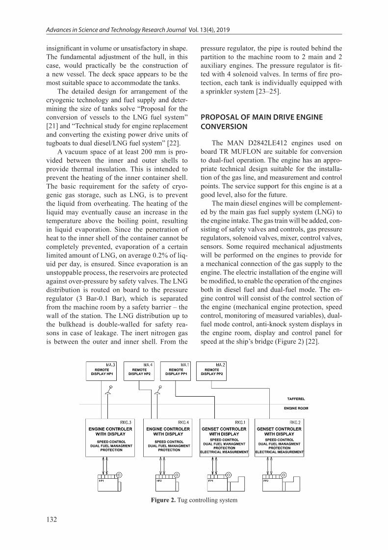
The main diesel engines will be complement-ed by the main gas fuel supply system (LNG) to the engine intake. The gas train will be added, con-sisting of safety valves and controls, gas pressure regulators, solenoid valves, mixer, control valves, sensors. Some required mechanical adjustments will be performed on the engines to provide for a mechanical connection of the gas supply to the engine. The electric installation of the engine will be modified, to enable the operation of the engines both in diesel fuel and dual-fuel mode. The en-gine control will consist of the control section of the engine (mechanical engine protection, speed control, monitoring of measured variables), dual-fuel mode control, anti-knock system displays in the engine room, display and control panel for speed at the ship’s bridge (Figure 2) [22].
Figure 2. Tug controlling system
133
Advances in Science and Technology Research Journal Vol. 13(4), 2019
The safety (gas leakage into the engine room, gas pressure failure) is solved by the immediate shutdown of the gas supply to the engine (sole-noid valves and MGV (Master Gas Valve) with the main gas shut-off valve at the LNG tank outlet (Figure 3) [22, 26].
The control system uses engine protection from high exhaust gas temperature and the anti-knock system to prevent the engine knock. In case the anti-knock system registers the twist-ing of the engine (detonation combustion) of the dual fuel control system, it reduces the gas charge while simultaneously adding a diesel charge. If the detonation level is not reduced, the control system disconnects the gas supply to the engine and the engine only goes to the diesel. Switching back to the dual fuel system must be confirmed by the engine room operator.
If the exhaust gas temperature rises above the permitted limit, the dual fuel control system reduces the gas charge and adds a diesel charge. If there is no reduction in the exhaust gas tem-perature, the control system is maintained as de-scribed in the paragraph above [27].
Main engine block diagram
The philosophy of converting diesel engines to dual fuel engines consists in: • preservation of mechanical part of the engine
(cylinder block, connecting rod and piston group, cylinder head, turbocharger, mechani-cal equipment),
• incorporation of a new control section of the engine (mechanical control, protection, dual fuel system control, anti-knock system, moni-toring of variables),
• additional installation of the gas line, • controlled ventilation of the machinery room, • engine equipment (accessories), • adjustments of engine electrical installations, • adjustment of the mechanical design of the gas
line’s connection to the engines, • addition of safety features related to the addi-
tion of gaseous fuel to the ship.
The original diesel system remains un-changed. It is only supplemented with fuel con-trol to provide accurate information on the sup-plied amount of diesel fuel.
By adjusting the ventilation of the machinery room, the possibility of continuous ventilation is achieved. Such treatment prevents any accumula-tion of spilled gas in the engine room.
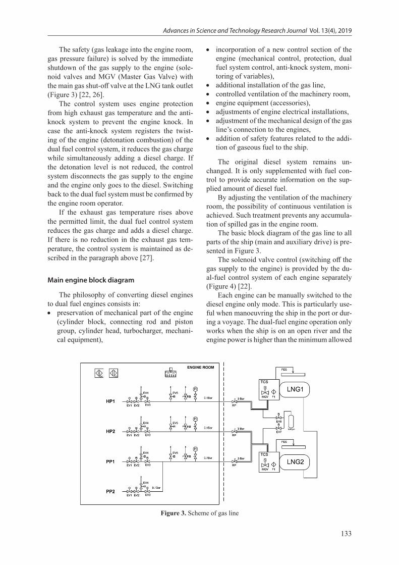
The basic block diagram of the gas line to all parts of the ship (main and auxiliary drive) is pre-sented in Figure 3.
The solenoid valve control (switching off the gas supply to the engine) is provided by the du-al-fuel control system of each engine separately (Figure 4) [22].
Each engine can be manually switched to the diesel engine only mode. This is particularly use-ful when manoeuvring the ship in the port or dur-ing a voyage. The dual-fuel engine operation only works when the ship is on an open river and the engine power is higher than the minimum allowed
Figure 3. Scheme of gas line

Advances in Science and Technology Research Journal Vol. 13(4), 2019
134
level (usually 20%). If the engine control system evaluates the hazard due to the use of gaseous fuel (a gas shortage, low gas pressure), or other fail-ure, the engine immediately runs on diesel fuel only, or the engine is stopped (Figure 5) [24, 25].
Block diagram of the gas line
The basic block diagram of the gas line to all parts of the ship (main and auxiliary drive) and the layout of the gas technology is shown in Figure 3.
The high-pressure part of the distribution line with double-jacketed piping and gas pressure regulators (from 300 kPa to 10 kPa) for engines (main drives have separate gas pressure regula-tors; auxiliary drives have a common gas pressure regulator) are on the deck. Each high-pressure branch is connected to the nitrogen supply, as part of accessories. The MGV (Master Gas Valve) is installed in the TCS module which serves as an emergency valve that shuts off the gas supply to the outlet pipeline. If the MGV is switched off, the branch pertaining to the engine must be purged with nitrogen before refilling with gas again. The failure of the double-jacketed piping is signalled to the control system of the engine for the respec-tive branch (Figure 5), in the case of activation of the signal, the engine will be switched to the diesel-only operation and at the MGV is closed immediately [24].
The low-pressure distribution line continues from the pressure regulator through the pipeline to the shut-off valves (solenoid valves) in the en-gine room of each main drive engine separately, the auxiliary engines have one common gas sup-ply (Figure 3, Figure 6) [26, 27].
On the pipeline upstream of the pair of sole-noid valves there is a solenoid blow-off valve and a pressure relief valve, which opens at pressure surges that may arise when opening and closing the pair of solenoid valves. Furthermore, a visual pressure gauge and a low-pressure sensor for the engine control system are located on the line. A blow-off valve which opens when both solenoid valves are closed is located between the pair of solenoid valves. Behind a pair of solenoid valves, there is a regulating valve controlling the gas dose at dual fuel engine mode. The methane and CO leakage sensors are located in the engine room. In case the methane leak sensor is activated, the con-trol systems of all engines shut off the gas supply and change over to the diesel-only operation. All the MGVs are closed as well. Switching back to the dual-fuel system must be confirmed by the en-gine room operator [18, 26].
Principle of engine operation
Single-point gas supply to the engine with a gas mixer (Single Point Injection – SPI)
The basic diagram showing the principle of operation of dual-fuel engines with single-point (central supply) gas supply to a common intake manifold is presented in Figure 7.
This system is mostly for high-speed engines. This system is applicable to the conversion of the main and auxiliary engines of TR Muflon.
The diesel engine is complemented by a gas line consisting of a gas filter, two solenoid valves, venting solenoid valve, zero gas pressure regu-lator, control valve for a quantity of gas to the mixer, and gas pressure sensors. The gas enters
Figure 4. Master drive management

135
Advances in Science and Technology Research Journal Vol. 13(4), 2019
through the diffuser into the intake manifold of the engine in front of the turbocharger, then the gas-air mixture is compressed and blown through the intercooler to the engine cylinders. At the end of the compression stroke of the piston in the cyl-inder, a dose of diesel fuel is injected to ignite the compressed mixture of air and gas. The engine starts and runs on diesel.
The dual-fuel system is switched on from a certain engine load level (usually 20 %), and at the same time, the vessel must be out of port handling and out of bunker handling. The switch-ing to the dual-fuel mode and back is automatic. The proportion of the gas control valve opening and the amount of diesel takes place according to the set algorithm, depending on the engine speed and load. It is assumed that once a minimum load is attained (typically 20%), the control system
sequentially reduces the dose of liquid fuel (die-sel fuel), while simultaneously adding a gas charge. After reaching the desired diesel charge (11 to 20 %), the engine speed control will occur through a change of the gas charge to maintain the desired diesel fuel charge throughout the en-tire load range.
The actual engine performance (power) is evaluated based on a 3D map consisting of engine speed, intake manifold pressure and the position of the diesel and gas controls. Depending on the detected power, the control system decides on the ratio of diesel and gas.
Multi-point gas supply to the engine (MPI Multi Point Injection) is used for large and slow running engines. The gas supply pressure before the injection valve is about 3 Bar. Given the na-ture of the high-pressure multi-point gas injection
Figure 5. Blow diagram master drive
Figure 6. Gas line on the vessel

Advances in Science and Technology Research Journal Vol. 13(4), 2019
136
into the engine, this principle is not applicable to the conversion of the TR Muflon engines [18].
Determining the energy for evaporation
The evaporation calculation applies the maxi-mum dose of gas at a minimum dose of diesel, re-gardless of how the vessel is operated. The maxi-mum gas consumption for one cryogenic tank and one main power drive with one auxiliary power drive is 231.8 + 21.5 = 253.3 dm3/h of LNG.
The energy for evaporation is:
𝑃𝑃𝑜𝑜𝑜𝑜1000 = 𝑄𝑄 ∙ 𝑘𝑘 ∙ 𝑞𝑞𝑚𝑚𝑚𝑚 = 253.3 ∙ 1.1 ∙ 0.4 ∙ 548.473.6 = 16.980 𝑘𝑘𝑘𝑘
𝑃𝑃𝑜𝑜𝑜𝑜1000 = 𝑄𝑄 ∙ 𝑘𝑘 ∙ 𝑞𝑞𝑚𝑚𝑚𝑚 = 253.3 ∙ 1.1 ∙ 0.4 ∙ 548.473.6 = 16.980 𝑘𝑘𝑘𝑘
(1)
where: Q amount of gas [kg/h], gml specific heat of vaporisation [kJ/kg], ρLNG 0.4 [kg/dm3].
Note: For the evaporation parameters, the specific heat of vaporization was given for pure methane. This is because LNG will be cleaned mostly of heavier hydrocarbons, thereby increas-ing the proportion of methane in LNG. Plain Rus-sian natural gas already has more than 95% meth-ane in its basic composition. [16]. For a possible error, the gas quantity coefficient k = 1.1 is taken.
The energy for heating of gas to 15°C is:
𝑃𝑃𝑜𝑜ℎ1000 = 𝑄𝑄 ∙ 𝑘𝑘 ∙ 𝑐𝑐𝑐𝑐 ∙ 𝛥𝛥𝛥𝛥 = 253.3 ∙ 1.1 ∙ 0.4 ∙ 2.0 ∙ (162 + 15)3.6 = 10.959 𝐾𝐾𝑊𝑊
𝑃𝑃𝑜𝑜ℎ1000 = 𝑄𝑄 ∙ 𝑘𝑘 ∙ 𝑐𝑐𝑐𝑐 ∙ 𝛥𝛥𝛥𝛥 = 253.3 ∙ 1.1 ∙ 0.4 ∙ 2.0 ∙ (162 + 15)3.6 = 10.959 𝐾𝐾𝑊𝑊
𝑃𝑃𝑜𝑜ℎ1000 = 𝑄𝑄 ∙ 𝑘𝑘 ∙ 𝑐𝑐𝑐𝑐 ∙ 𝛥𝛥𝛥𝛥 = 253.3 ∙ 1.1 ∙ 0.4 ∙ 2.0 ∙ (162 + 15)3.6 = 10.959 𝐾𝐾𝑊𝑊
(2)
where: Q amount of gas [kg/h], cp specific heat [kJ/kg x K], ρLNG 0.4 [kg/dm3].
Note: For the heating parameters, the specific heat was given for pure methane. This is because LNG will be cleaned mostly of heavier hydrocar-bons, thereby increasing the proportion of meth-ane in LNG. Plain Russian natural gas already has more than 95% methane in its basic composition. [16]. For a possible error, take the gas quantity coefficient k = 1.1 is taken.
The energy for evaporation and heating of gas to 15°C is:
𝑃𝑃𝑜𝑜𝑜𝑜𝑜𝑜𝑜𝑜 = (𝑃𝑃𝑜𝑜𝑜𝑜𝑜𝑜𝑜𝑜𝑜𝑜 + 𝑃𝑃𝑜𝑜ℎ𝑜𝑜𝑜𝑜𝑜𝑜)𝑥𝑥 𝑘𝑘𝑘𝑘 = (16.980 + 10.959) 𝑥𝑥 1.2 = 33.527 𝑘𝑘𝑘𝑘 𝑃𝑃𝑜𝑜𝑜𝑜𝑜𝑜𝑜𝑜 = (𝑃𝑃𝑜𝑜𝑜𝑜𝑜𝑜𝑜𝑜𝑜𝑜 + 𝑃𝑃𝑜𝑜ℎ𝑜𝑜𝑜𝑜𝑜𝑜)𝑥𝑥 𝑘𝑘𝑘𝑘 = (16.980 + 10.959) 𝑥𝑥 1.2 = 33.527 𝑘𝑘𝑘𝑘
(3)
where: kv area reserve coefficient of 1.2.
For the technological (TLG) diagram, the power input for heating and evaporation of about 35 kW will be considered.
Figure 7. Dual-fuel principle of engine operation

137
Advances in Science and Technology Research Journal Vol. 13(4), 2019
PID diagrams
The technological connection diagram for cooling the main power drives is shown in Figure 8.
The diagram shows an engine cooling system for the main MAN D 2842 LE412 drives with the power supplied in diesel and vaporised natural gas. The diagram shows the dimensions of the wa-ter pipes. These are calculated in the programme in which the technological diagram was prepared. The flow rate of the glycol-water coolant in the main circuit is determined by the original cool-ing circuit. The LNG evaporator heating system works on dual fuel operation when the pump for the inlet to the evaporator is started.
The LNG evaporator heating system is con-nected to the existing cooling circuit with a separate pump and a 3-way valve. The system works when the dual-fuel operation is started, which starts the pump for the inlet to the evapo-rator. The temperature of the feed mixture must be regulated to the temperature specified by the supplier of the cryogenic tanks, including the Tank Connection Space (TCS); it was deter-mined as 75°C. This is regulated by the three-way valve in the reverse mixing mode of the evaporator. The required power for the given evaporation mode will be controlled by the fre-quency converter of the CP1 pump depending on the gas temperature and the pressure ratios at the TCS outlet (15°C).
In order to prevent the supercooled air return to the engine, the temperature was the same as the engine inlet at 70°C. The flow rate of coolant through pipes and fittings to the evaporator inlet is about 0.93 m / s (DN50) [18].
Management of gas and heating lines
For safety reasons, the authors propose to install the route of the pressurised gas upstream of the gas pressure regulator besides the cryo-genic tanks, mirrored to one another on the deck with the proper covers. Gas pressure regulators for 300/10 kPa for the main power drives will also be placed on the deck, and a branch will be made from the pressure branch for the auxiliary drives with its own gas pressure regulator (inde-pendent of the main power drives). Only the gas under the pressure of 10 psi will enter into the machinery room.
The route for evaporator heating in the TCS is not guided together with the gas line; instead, it is split at the outlet of the TCS. The gas line routing and heating line is shown in Figure 9 and Figure 10.
Determining the dimensions of gas lines
The design temperature of all of the follow-ing cases is 15°C. Due to the external influences and an increased temperature of the engine room, the actual temperature may be higher, and so the
Figure 8. The technological connection diagram for cooling the main power drives

Advances in Science and Technology Research Journal Vol. 13(4), 2019
138
calculation has taken into consideration a gas temperature of 30°C. The amount of gas for the main and auxiliary drives with a 10% margin is (133.5 + 12.4)∙1.1 = 160.5 nm3/h.
The pressure level of 300 kPa
For the pipeline length of about 6.0 meters (common from two TCSs), the nominal diameter of DN40 and 4 pieces of 90° elbows, the pressure loss is about 0.22 kPa. The speed of gas flow in the pipeline is about 9.9 m/s.
The pressure level of 10 kPa
The pipe length is planned to be the same for each main drive and is about 4.2 metres. For 6
pieces of 90° elbows, the proposed diameter of DN65 and the length indicated, the pressure loss is about 0.26 kPa. The speed of gas flow in the pipeline is about 13.6 m/s.
PROPOSED AUXILIARY DRIVE ENGINE REBUILDING
Technical specifications
The DEUTZ BF4M2012C engines, which are suitable for rebuilding for dual fuel opera-tion, are used on the TR MUFLON tugboat. The existing generators meet the requirements for the required functions.
Figure 10. The gas and heating line
Figure 9. The gas and heating line

139
Advances in Science and Technology Research Journal Vol. 13(4), 2019
The auxiliary drive diesel engines will be complemented by the main gas fuel supply sys-tem (LNG) to the engine’s intake. The gas lines consisting of safety valves and controls, gas pres-sure regulators, solenoid valves, mixer, control valves, and sensors will be added. Some required mechanical adjustments will be performed on the engines to ensure a mechanical connection of the gas supply to the engine. The electric installation of the engine will be modified to provide both diesel and dual-fuel operation. The engine control will consist of the control section of the engine (mechanical engine protection, speed control, monitoring of measured variables, measuring electrical parameters of the generator, controlling the switch for power output of the generator), dual-fuel mode control, an anti-knock system dis-play in the engine room, and a speed control panel on the bridge deck (Figure 2).
The safety (gas leakage into the engine room, gas pressure failure) is solved by the immediate shutdown of the gas supply to the engine (sole-noid valves and MGV (Master Gas Valve), the main gas shut-off valve at the outlet from the LNG tanks (Figure 11 and Figure 3).
The steering system uses engine protection from high exhaust gas temperature and anti-knock system to prevent engine knock. In case the anti-knock system detects an engine knock (detonating combustion), the control system for controlling the dual fuel supply will reduce the amount of gas and increase the amount of diesel. If the knock (detonation) level is not reduced, the control system disconnects the gas supply to the
engine and the engine only goes to diesel. Switch-ing back to the dual fuel system must be confirmed by the engine room operator (Figure 11) [18].
If the exhaust gas temperature rises above the permitted limit, the dual fuel control system reduces the gas charge and adds a diesel charge. If there is no reduction in the exhaust gas tem-perature, the control system disconnects the gas supply to the engine and the engine only goes to diesel. Switching back to the dual fuel system must be confirmed by the engine room operator (Figure 11) [25].
The auxiliary drive control system measures and evaluates the generator’s electrical param-eters, pinning the generator to the ship’s dis-tribution system (grid). There are two auxiliary drives on the ship, which are considered to oper-ate continuously. According to both the sponsor and the operator, one auxiliary drive is enough to cover the ship’s consumption. In case of a mal-function or a planned use of the second auxiliary drive, the second auxiliary drive can take the load from the first one through by phase configura-tion. This ensures a smooth transition of the load from one to the other auxiliary drive (i.e. without power interruption).
In case of failure of a running auxiliary drive, the second drive starts immediately and assumes the load so that the power outage is as short as pos-sible, or when in certain types of failures, a sec-ond auxiliary power unit starts and takes over the load before the malfunctioning drive stops [18].
Figure 11. Block diagram of auxiliary engines

Advances in Science and Technology Research Journal Vol. 13(4), 2019
140
Auxiliary engine block diagram
The philosophy of converting die-sel auxiliary engines into a dual-fuel system (Figure 11, Figure 12) is the same as that of the main engine conversion.
Connecting the generators of auxiliary drives to the existing substation is carrie dout in such manner that the functionality is preserved of all other parts, not affected by the reconstruction of the drive units to the dual-fuel mode. The main functional elements remain intact as well.
Principle of engine operation
The operation principle of the dual fuel auxil-iary engine system is the same as the principle of the main engine system.
It is also possible to use the SPI or MPI sys-tem, where the difference from the main drive system is that the actual engine load is measured by the electric power output from the generator. Each auxiliary drive has a separate measurement of voltage, frequency and current measurement on the generator. From these values, the control system evaluates the electrical load of the genera-tor, and thus the engine (Figure 12) [18].
Changes in electrical wiring
All newly installed components on the ship will also have new wiring. It will only be connected to the existing wiring in the main
switchboard for powering new devices, their control, signalling, etc. The original wiring will not be needed for new installations or wiring because new equipment will be installed. When installing new electrical wiring, the existing cable routes, or designated, points already des-ignated for this purpose will be used as much as possible. If this is not possible, new wiring will be installed.
All engines will have a small switchboard in-stalled with the control system for the engine, the dual-fuel system, and the anti-knock system. The basic control elements will also be placed on the switchboard.
Displays will be located on the ship’s bridge, directly linked to the control system of the en-gines of both main and auxiliary drives, on which all engine control system data, as well as drive controls, will be shown.
The engine operator panel will include the controls for switching and generator load syn-chronisation. This control system measures all the electrical parameters of the generator, also includes generator protection and operator display.
The generators will be connected to the main switchboard. The switching controls will be re-placed with new ones, in order to satisfy the requirements for generator synchronisation. If necessary, security (circuit-breaking) and out-let components will be added for connection of new devices [25].
Figure 12. Blow diagram auxiliary drive
141
Advances in Science and Technology Research Journal Vol. 13(4), 2019
Determining the dimensions of gas lines
The amount of gas for the auxiliary drives will be rated for both engines operating simul-taneously (to cover load mutually). The 300 kPa branch of the main drive pipeline is not crucial for auxiliary drives in terms of the pressure losses; therefore, their parameters will be calculated only in terms of dimensions.
The amount of gas for auxiliary drives with a 10 % margin is (12.4 + 12.4)∙1.1 = 27.3 nm3/h.
The pressure level of 300 kPa
A pipe diameter of DN25 is enough for the auxiliary drives, with gas flow speed in the pipes of 4,3 m/s.
The pressure level of 10 kPa
The pipe length is planned to be the same for each auxiliary drive and is about 7.4 metres. For 6 pieces of 90° elbows, the proposed diameter of DN40 and the length indicated, the pressure loss is about 0.11 kPa. The speed of gas flow in the pipeline is about 6.1 m/s [18, 27].
LNG BUNKERING PROPOSAL
Refuelling of the tugboats would take place in the terminals, and vessels would operate only on diesel when manoeuvring in the terminal. The authors propose that the concept deals with the possibility of refuelling the vessel from starboard and port side equally. The maritime vessels are equipped with standard connectors that are likely to be excessive in size (unnecessarily large dimen-sions) for inland waterways, because the capacity of maritime cryogenic tanks is much larger. It was as-sumed that the sufficient time period for bunkering (without the lost time for freeze-drying, pressure balancing, etc.) will be about 2 hours, and the bun-kering capacity of about 100 m3 for the ship would represent the LNG flow rate of about 50 m3/h. A diameter of filler opening of 80 to 100 mm would be sufficient for this amount [18, 28].
CONCLUSION
LNG as a fuel can reduce the environmental impact of the transport sector, which is already very serious and growing. At present, LNG is
the only alternative to the fuels currently used in freight transport. Batteries are too heavy; filters and scrubbers solve the problem at the end of the pipe and biofuels have several inherent problems.
There are several regulations that apply to equipment, their design, and properties that set re-quirements for ensuring the safe use of LNG. It is possible to convert the TR Muflon push tug. In terms of the engine design and components, there is no significant impediment to such a rebuilding. In this paper, a comprehensive design of the main and auxiliary engine remodelling, as well as the design of the vessel’s auxiliary tanks, are presented. Such a conversion methodology is partly applicable to an-other type of tug, considering the individual speci-ficities. However, the conversion will also change some of the basic parameters of the vessel:
With the TR Muflon tug the centre of grav-ity of the weight increases, due to placing both cryogenic tanks and TCS on the main deck, re-quiring its static reinforcement. The total weight of LNG-filled and TCS-filled tanks is expected to be around 30 tonnes for TR Muflon. The fire sys-tem with its impounding tanks will increase the weight by 2 tons. In the case of auxiliary drives with generators, due to the use of a relatively new technology, weight reduction will not be possible.
It can be assumed that for the TR Muflon tug, the centre of gravity position in the transverse di-rection will not change due to the distribution of cryogenic tanks, including the necessary equip-ment. Only the position of the centre of grav-ity in the longitudinal direction will be changed to backwards.
Due to the change in weight during the con-version of tugs, it is a prerequisite to change their navigability. Their draft will increase, and by changing the centre of gravity backwards, it will be necessary to compensate for excessive hoist-ing of the tug by ballasting. It is assumed that the design changes will also increase the fuel con-sumption of vessel.
As the fuel base only extends to LNG, the im-pact on the environment with the risks of original fuel is reduced only to the generation of pollut-ants in the exhaust where it is expected to reduce PM by about 40% and NOx by about 70%.
REFERENCES
1. Jurkovic, M., Kalina, T., Sosedova, J., Tvrda, E. Globalisation of the LNG trade in Caspian region. In: Globalization and its socio-economic conse-

Advances in Science and Technology Research Journal Vol. 13(4), 2019
142
quences. 16th international scientific conference: proceedings, PTS I-V. Rajecke Teplice, Slovakia. 05–06, 2016, 793–799.
2. Ota, J. Kryogenika. CVUT, Prague, 1986.3. Thiruvengadam, A., Besch, M., Padmanaban, V.,
Pradhan, S., Demirgok, B. Natural gas vehicles in heavy-duty transportation-A review. Energy Policy. Volume 122, 2018, 253–259. https://doi.org/10.1016/j.enpol.2018.07.052.
4. Kramer, U., Ferrera, M., Henning, K., David, M., Magnusson, I. Natural Gas/Methane Fuels: Euro-pean Automotive Fuel Quality and Standardization Requirements, 2015.
5. Kalina, T., Jurkovic, M., Grobarcikova, A. LNG – Great opportunity for the inland water transport. In: Transport means 2015: proceedings of the 19th international scientific conference: Oc-tober 22–23, 2015, Kaunas University of Technol-ogy, 2015, 489–492.
6. European Environmental Agency. Greenhouse Gas Emissions from Transport. European Environment Agency. Copenhagen (DK), 2015.
7. International Maritime Organization. Third IMO Greenhouse Gas Study. IMO. London, 2015.
8. Iannaccone, T., Landucci, G., Scarponi, G.E., Bon-vicini, S., Cozzani, V. Inherent safety assessment of alternative technologies for LNG ships bun-kering, Ocean Engineering, 185, 2019, 100–114. https://doi.org/10.1016/j.oceaneng.2019.05.028.
9. Skrucany T., Kendra M., Stopka O., Milojevic S., Figlus T., Csiszar C. Impact of the Electric Mo-bility Implementation on the Greenhouse Gases Production in Central European Countries, Sus-tainability, 11(18), 2019, Article no. 4948. DOI: 10.3390/su11184948.
10. Sarkan, B., Stopka, O., Gnap, J., Caban, J. Inves-tigation of Exhaust Emissions of Vehicles with the Spark Ignition Engine within Emission Con-trol. Transbaltica 2017: Transportation Science and Technology, Book Series: Procedia Engineer-ing, 187, 2017, 775–782, DOI: 10.1016/j.pro-eng.2017.04.437.
11. MARPOL. International Convention for the Pre-vention of Pollution from Ship. Available at: http://www.marpoltraining.com/MMSKOREAN/MAR-POL/intro/index.html, 2006.
12. Skrucany, T, Gnap, J. Energy intensity and green-house gases production of the road and rail Cargo transport using a software in simulate the energy consumption of a train. In: Telematics – support of transport: 14th international conference on Trans-port systems telematics, TST 2014: Katowice/Kraków/Ustroń, Poland, October 22–25, 2014: se-lected papers. – Berlin: Springer-Verlag, 2014.
13. Galierikova, A., Sosedova, J. Environmental as-
pects of transport in the context of development of inland navigation. In: Ekológia (Bratislava), 35( 3), 2016, 279–288.
14. David, A., Piala, P., Stupalo, V. ICTTE 2016. In-ternational conference on Traffic and transport engineering: November 24–25, 2016, Belgrade, Serbia. – Belgrade: City Net Scientific Research Center, 2016.
15. Skrucany, T., Kendra, M., Jurkovic, M., Kalina, T. Environmental Comparision of Different Trans-port Modes. In: Nase more = Our sea: znanstveno-strucni casopis za more i pomorstvo, 65(4), 2018, 192–196. DOI: 10.17818/NM/2018/4SI.5.
16. General rules for reconstruction of vessels. Deci-sion of the Maritime Safety Committee (MSC), 285(86).
17. Kalina, T., Jurkovic, M., Jancosek, L., Kadnar, R. Proposal for the conversion of vessels to the LNG fuel system. In: CMDTUR2018, 8th international scientific conference. Zilina, Slovakia, 2018.
18. LNG Masterplan for Rhine-Main-Danube /TEN-T Network Programme/. Technical study for engine replacement and converting the existing power drive units of tug boats to dual diesel/liquefied natural gas fuel system.
19. Kalina, T., Jurkovic, M., Sapieta, M., Binova, H., Sapietova, A. Strength Characteristics of LNG Tanks and their Application in Inland Navigation. In. AD ALTA-Journal of Interdisciplinary Re-search, 7(2), 2017, 274–281.
20. European Standard EN 13 645 – Installations and equipment for Liquefied Natural Gas – Design of on-shore installations with a storage capacity be-tween 5t and 200t.
21. EN 13 458 – Cryogenic vessels – Static vacuum insulated vessels.
22. EC 94/9/EC – Equipment and Protective systems intended for use in potentially explosive atmo-spheres (ATEX).
23. EN 60079–10 – Electrical apparatus for explosive gas atmospheres – Classification of hazardous areas.
24. PED 97/23/EC – Pressure Equipment Directive. 25. EN 60079–10 – Electrical apparatus for explosive
gas atmospheres – Classification of hazardous areas.26. EN 1160 – Installation and equipment for Lique-
fied Natural Gas – General characteristics of lique-fied natural gas.
27. EN 13480 – Metal piping systems. 28. Jurkovic, M., Kalina, T., Turcan, R., Gardlo, B.
Proposal of an enhanced safety system on board of the inland vessel. In: MATEC web of conferences. LOGI 2017 – 18th international scientific confer-ence: České Budějovice, Czech Republic, October 19, Vol. 134, art. no. 00022. 2017.