prophecy infinity - · pdf file14 drill tibial corners 15 tibial bone resection 16 talar...
TRANSCRIPT

PROPHECY INFINITY
Pre-Operative Navigation GuidesSURGIC AL TECHNIQUE
® ®

PROPHECY® INFINITY® Pre-Operative Navigation Guides
SURGICAL TECHNIQUE
SURGEON DESIGN TEAM
The PROPHECY® INFINITY® Total Ankle System was developed in conjunction with:
Robert B. Anderson, MDOrthoCarolinaCharlotte, NC
Gregory C. Berlet, MDOrthopedic Foot and Ankle CenterColumbus, OH
W. Hodges Davis, MDOrthoCarolinaCharlotte, NC
Steven L. Haddad, MDIllinois Bone and Joint InstituteChicago, IL
Thomas H. Lee, MDOrthopedic Foot and Ankle CenterColumbus, OH
Murray J. Penner, MD FRCSCProvidence Health CareVancouver, BC

Contents
Chapter 1 4 Product Information 4 PROPHECY® INFINITY® Alignment Guide Product Information 4 Intended Use 4 INFINITY®Total Ankle Product Information 5 Indications/Contraindications 6 CT Scan Protocol
Chapter 2 7 Surgical Technique 7 Tibial Alignment Guide Fluoroscopic Check Assembly 8 Surgical Approach 8 Tibial Alignment Guide 11 Install Coronal Sizing Guide 14 Drill Tibial Corners 15 Tibial Bone Resection 16 Talar Alignment Guide 19 Talar Bone Resection 20 Remove Tibial Bone Resection 23 Tibial Tray Trialing and AP Sizing 26 Tibial Peg Broaching 27 Talar Component Sizing and Positioning 29 Talar Chamfer Resections 33 Polyethylene Thickness 34 Talar Peg Drilling 35 Tibial Component Implantation 38 Talar Component Implantation 39 Polyethylene Bearing Installation 44 Explant Information 44 Postoperative Management
Appendix A 45 Conversion to Standard Instrumentation
Appendix B 56 INBONE® Talar Dome Resection Technique
Appendix C 59 PROPHECY® INBONE® Talar Dome Technique
Appendix D 68 INFINITY® Instrumentation
Appendix E 77 Implant Specifications
Appendix F 79 Ordering Information
3
Proper surgical procedures and techniques are the responsibility of the medical professional. The following guidelines are furnished for information purposes only. Each surgeon must evaluate the appropriateness of the procedures based on his or her personal medical training and experience. Prior to use of the system, the surgeon should refer to the product package inserts (145283) for complete warnings, precautions, indications, contraindications and adverse effects. Package inserts are also available by contacting the manufacturer. Contact information can be found on the back of this surgical technique and the package insert is available on the website listed: wright.com, under the link for Prescribing Information.
Please contact your local Wright representative for product availability.
1chap
ter
ProductInformation
Chapter 1 Product Information4
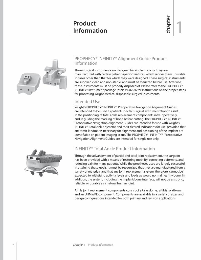
PROPHECY® INFINITY® Alignment Guide Product InformationThese surgical instruments are designed for single use only. They are manufactured with certain patient-specific features, which render them unusable in cases other than that for which they were designed. These surgical instruments are supplied clean and non-sterile, and must be sterilized before use. After use, these instruments must be properly disposed of. Please refer to the PROPHECY® INFINITY® Instrument package insert #146636 for instructions on the proper steps for processing Wright Medical disposable surgical instruments.
Intended UseWright’s PROPHECY® INFINITY® Preoperative Navigation Alignment Guides are intended to be used as patient-specific surgical instrumentation to assist in the positioning of total ankle replacement components intra-operatively and in guiding the marking of bone before cutting. The PROPHECY® INFINITY® Preoperative Navigation Alignment Guides are intended for use with Wright’s INFINITY® Total Ankle Systems and their cleared indications for use, provided that anatomic landmarks necessary for alignment and positioning of the implant are identifiable on patient imaging scans. The PROPHECY® INFINITY® Preoperative Navigation Alignment Guides are intended for single use only.
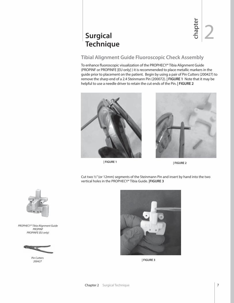
INFINITY® Total Ankle Product InformationThrough the advancement of partial and total joint replacement, the surgeon has been provided with a means of restoring mobility, correcting deformity, and reducing pain for many patients. While the prostheses used are largely successful in attaining these goals, it must be recognized that they are manufactured from a variety of materials and that any joint replacement system, therefore, cannot be expected to withstand activity levels and loads as would normal healthy bone. In addition, the system, including the implant/bone interface, will not be as strong, reliable, or durable as a natural human joint.
Ankle joint replacement components consist of a talar dome, a tibial platform, and an UHMWPE component. Components are available in a variety of sizes and design configurations intended for both primary and revision applications.

Chapter 1 Product Information 5
IndicationsThe INFINITY® Total Ankle is indicated for patients with ankle joints damaged by severe rheumatoid, post-traumatic, or degenerative arthritis.
The INFINITY ® Total Ankle is additionally indicated for patients with a failed previous ankle surgery.
CAUTION: In the United States, the ankle prosthesis is intended for cement use only.
ContraindicationsContraindications include: 1. Osteomyelitis;2. Insufficient bone stock or bone quality;3. Infection at the ankle site or infections at distant sites that could migrate to
the ankle;4. Sepsis;5. Vascular deficiency in the ankle joint;6. Skeletally immature patients (patient is less than 21 years of age at the time
of surgery);7. Cases where there is inadequate neuromuscular status (e.g., prior paralysis,
fusion and/or inadequate abductor strength), poor skin coverage around the joint which would make the procedure unjustifiable;
8. Neuropathic joints;9. Excessive loads as caused by activity or patient weight;10. Patient pregnancy;11. Severely compromised musculature or neuromuscular function.12. Uncooperative patient or patient with neurologic disorders, incapable of
following instructions
WARNING: This device is not intended for subtalar joint fusion or subtalar joint impingement. Please carefully evaluate the anatomy of each patient before implantation. High levels of activity may increase the risk of adverse events. Surgeons should carefully consider the advisability of ankle replacement in patients with metabolic disorders or pharmacological treatments that impair bone formation or with conditions that may impede wound healing (e.g., end stage diabetes or malnutrition).
Prior to use of the system, the surgeon should refer to the product package insert for complete warnings, precautions, indications, contraindications and adverse effects. Package inserts are also available by contacting the manufacturer. Contact information can be found on the back of this surgical technique and the package insert is available on the website listed.

6
CT Scan Protocol PROPHECY® INFINITY® Preoperative Navigation Guides are patient-specific instruments designed using patient anatomy from a CT scan of the patient’s extremity. One significant requirement for a successful case is adhering to the PROPHECY® Ankle CT Scan Protocol document. Engineers at Wright Medical Technology have determined the necessary scanning parameters which are described in document #008380 and can be found on our website (http://documents.wmt.com/Document/Get/008380).
In every case, please have the scanning facility follow the specific instructions outlined in this document.
The Centers for Medicare & Medicaid Services (CMS) established a National Coverage Determination (NCD) for CT Scans. It states, in part, the following, “Diagnostic examinations of the head (head scans) and of other parts of the body (body scans) performed by computerized tomography (CT) scanners are covered if medical and scientific literature and opinion support the effective use of a scan for the condition, and the scan is: (1) reasonable and necessary for the individual patient.” CTs performed prior to total joint replacement procedures for diagnostic purposes may be considered medically necessary. In which case, the procedure should be billed using the CPT codes that accurately describe the imaging procedure furnished to the patient. These same images from the diagnostic CT scan may, in turn, be further utilized for developing the personalized cutting or navigation guides that are used in orthopaedic procedures. However, if providers perform CT scans solely for the purpose of developing personalized cutting instruments or guides, providers should contact the payer for billing and coverage guidance and/or the American College of Radiology with billing questions.
PROPHECY® Ankle CT Scan Protocol#008380
2chap
ter
Surgical Technique
Chapter 2 Surgical Technique
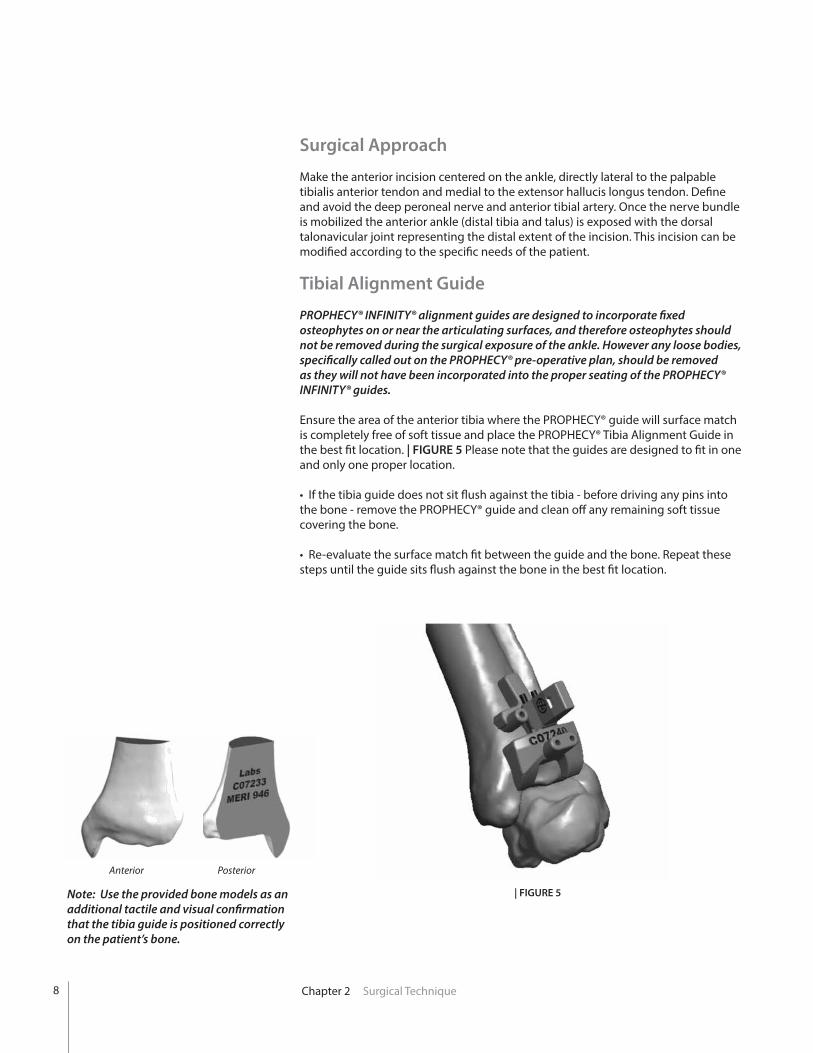
Tibial Alignment Guide Fluoroscopic Check AssemblyTo enhance fluoroscopic visualization of the PROPHECY® Tibia Alignment Guide (PROPINF or PROPINFE [EU only] ) it is recommended to place metallic markers in the guide prior to placement on the patient. Begin by using a pair of Pin Cutters (200427) to remove the sharp end of a 2.4 Steinmann Pin (200072). | FIGURE 1 Note that it may be helpful to use a needle driver to retain the cut ends of the Pin. | FIGURE 2
| FIGURE 1 | FIGURE 2
PROPHECY® Tibia Alignment GuidePROPINF
PROPINFE (EU only)
Pin Cutters200427
Cut two ½” (or 12mm) segments of the Steinmann Pin and insert by hand into the two vertical holes in the PROPHECY® Tibia Guide. |FIGURE 3
| FIGURE 3
7
Chapter 2 Surgical Technique
Note: Use the provided bone models as an additional tactile and visual confirmation that the tibia guide is positioned correctly on the patient’s bone.
| FIGURE 5
Anterior Posterior
Surgical Approach Make the anterior incision centered on the ankle, directly lateral to the palpable tibialis anterior tendon and medial to the extensor hallucis longus tendon. Define and avoid the deep peroneal nerve and anterior tibial artery. Once the nerve bundle is mobilized the anterior ankle (distal tibia and talus) is exposed with the dorsal talonavicular joint representing the distal extent of the incision. This incision can be modified according to the specific needs of the patient.
Tibial Alignment Guide
PROPHECY® INFINITY® alignment guides are designed to incorporate fixed osteophytes on or near the articulating surfaces, and therefore osteophytes should not be removed during the surgical exposure of the ankle. However any loose bodies, specifically called out on the PROPHECY® pre-operative plan, should be removed as they will not have been incorporated into the proper seating of the PROPHECY® INFINITY® guides.
Ensure the area of the anterior tibia where the PROPHECY® guide will surface match is completely free of soft tissue and place the PROPHECY® Tibia Alignment Guide in the best fit location. | FIGURE 5 Please note that the guides are designed to fit in one and only one proper location.
• If the tibia guide does not sit flush against the tibia - before driving any pins into the bone - remove the PROPHECY® guide and clean off any remaining soft tissue covering the bone.
• Re-evaluate the surface match fit between the guide and the bone. Repeat these steps until the guide sits flush against the bone in the best fit location.
8
Chapter 2 Surgical Technique
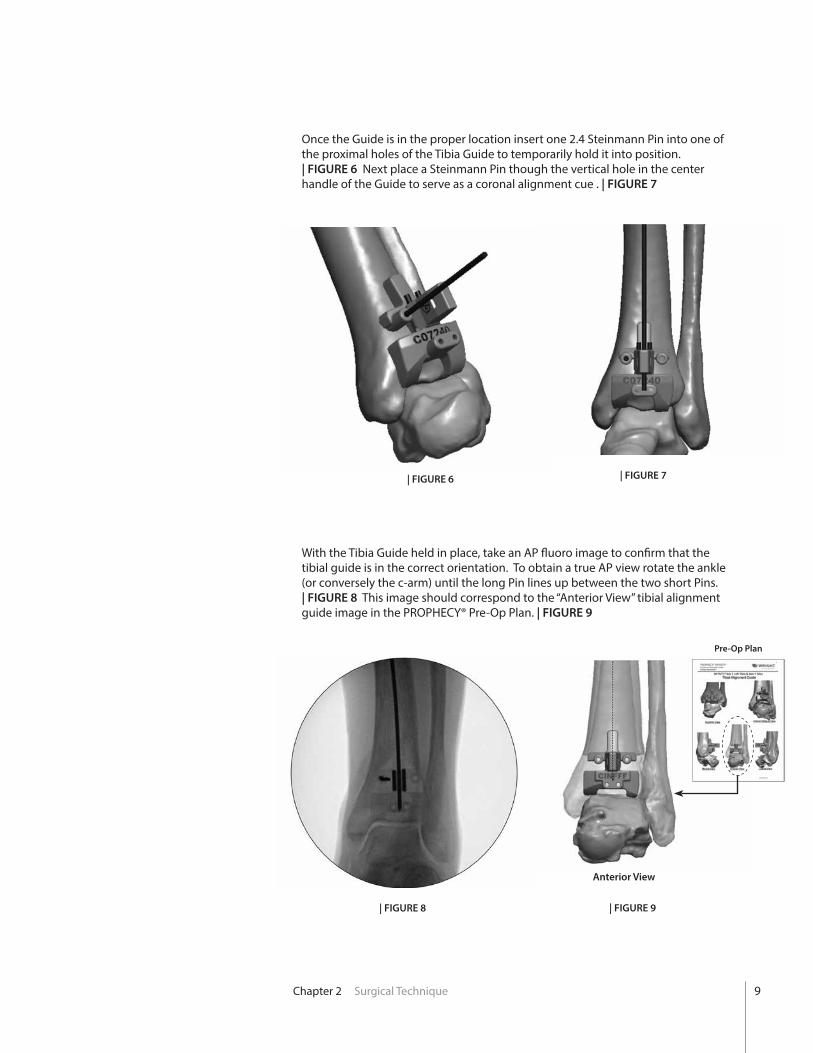
Once the Guide is in the proper location insert one 2.4 Steinmann Pin into one of the proximal holes of the Tibia Guide to temporarily hold it into position. | FIGURE 6 Next place a Steinmann Pin though the vertical hole in the center handle of the Guide to serve as a coronal alignment cue . | FIGURE 7
With the Tibia Guide held in place, take an AP fluoro image to confirm that the tibial guide is in the correct orientation. To obtain a true AP view rotate the ankle (or conversely the c-arm) until the long Pin lines up between the two short Pins. | FIGURE 8 This image should correspond to the “Anterior View” tibial alignment guide image in the PROPHECY® Pre-Op Plan. | FIGURE 9
| FIGURE 6
| FIGURE 8
| FIGURE 7
| FIGURE 9
Anterior View
Pre-Op Plan
9

Chapter 2 Surgical Technique
Be sure to center the ankle on the fluoro projection screen to minimize the risk of parallax imaging error.
If the intra-op image is significantly different that the pre-op plan remove the Tibia Guide as well as any Pins holding it in place. Ensure the periosteum has been cleaned from the tibia, and that skin retractors are effectively keeping all other soft-tissues from interfering with the Guide. It may also be beneficial to place the foot into slight plantarflexion and place a surgical bump under the tibia to elevate it. This allows the talus to drop away from the anterior tibia and prevent interference with the distal portion of the Tibia Guide.
Replace the Tibia Guide and repeat the procedure for AP fluoro check, using the opposite side pin hole to temporarily secure the Guide in place.
Note: By using only one pin to initially secure the Guide, adjustments can be made to the Guide location providing a second option to pin in place without finding the original pin hole.
10
Chapter 2 Surgical Technique
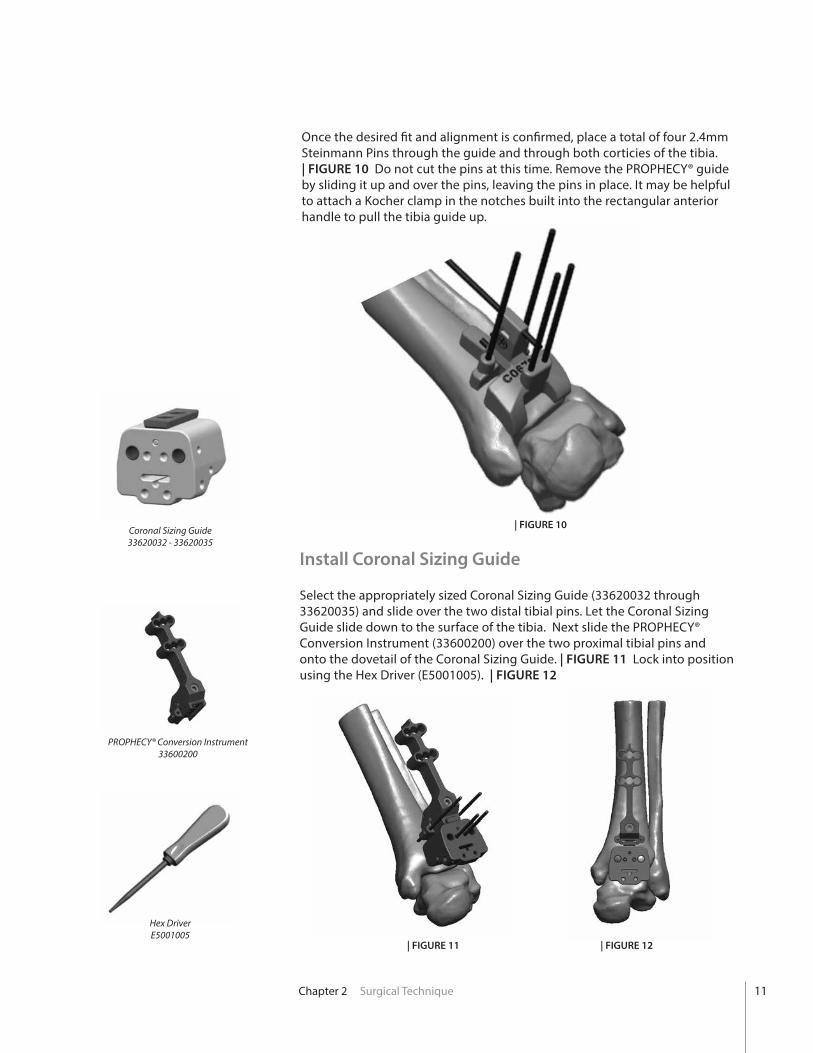
Once the desired fit and alignment is confirmed, place a total of four 2.4mm Steinmann Pins through the guide and through both corticies of the tibia. | FIGURE 10 Do not cut the pins at this time. Remove the PROPHECY® guide by sliding it up and over the pins, leaving the pins in place. It may be helpful to attach a Kocher clamp in the notches built into the rectangular anterior handle to pull the tibia guide up.
Install Coronal Sizing Guide
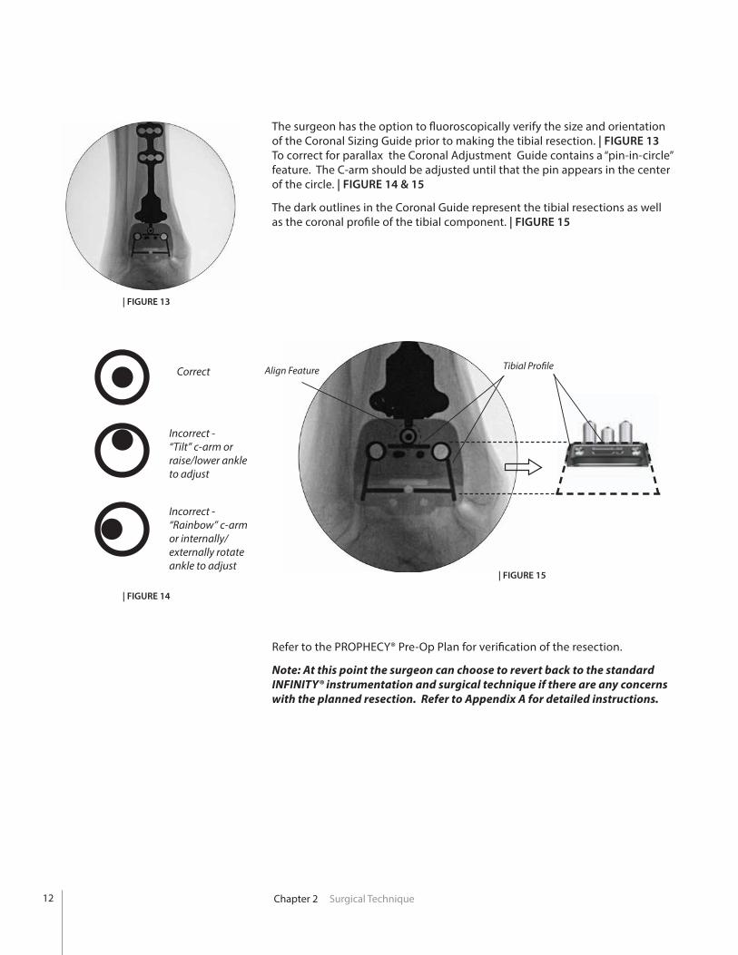
Select the appropriately sized Coronal Sizing Guide (33620032 through 33620035) and slide over the two distal tibial pins. Let the Coronal Sizing Guide slide down to the surface of the tibia. Next slide the PROPHECY® Conversion Instrument (33600200) over the two proximal tibial pins and onto the dovetail of the Coronal Sizing Guide. | FIGURE 11 Lock into position using the Hex Driver (E5001005). | FIGURE 12
| FIGURE 10
| FIGURE 12| FIGURE 11
Coronal Sizing Guide33620032 - 33620035
PROPHECY® Conversion Instrument33600200
Hex DriverE5001005
11
Chapter 2 Surgical Technique
| FIGURE 13
| FIGURE 14
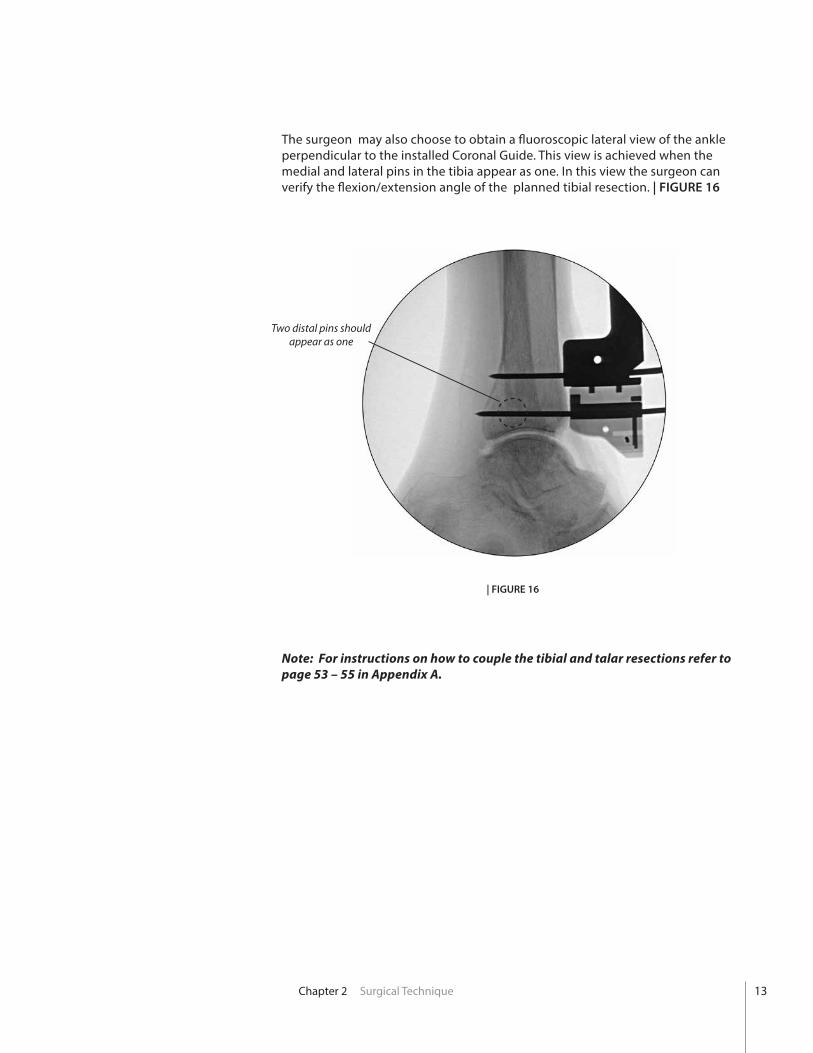
The surgeon has the option to fluoroscopically verify the size and orientation of the Coronal Sizing Guide prior to making the tibial resection. | FIGURE 13 To correct for parallax the Coronal Adjustment Guide contains a “pin-in-circle” feature. The C-arm should be adjusted until that the pin appears in the center of the circle. | FIGURE 14 & 15
The dark outlines in the Coronal Guide represent the tibial resections as well as the coronal profile of the tibial component. | FIGURE 15
Refer to the PROPHECY® Pre-Op Plan for verification of the resection.
Note: At this point the surgeon can choose to revert back to the standard INFINITY® instrumentation and surgical technique if there are any concerns with the planned resection. Refer to Appendix A for detailed instructions.
Correct
Incorrect -“Tilt” c-arm or raise/lower ankle to adjust
Incorrect -“Rainbow” c-armor internally/externally rotate ankle to adjust
Tibial ProfileAlign Feature
| FIGURE 15
12
Chapter 2 Surgical Technique
The surgeon may also choose to obtain a fluoroscopic lateral view of the ankle perpendicular to the installed Coronal Guide. This view is achieved when the medial and lateral pins in the tibia appear as one. In this view the surgeon can verify the flexion/extension angle of the planned tibial resection. | FIGURE 16
Note: For instructions on how to couple the tibial and talar resections refer to page 53 – 55 in Appendix A.
| FIGURE 16
Two distal pins should appear as one
13
Chapter 2 Surgical Technique
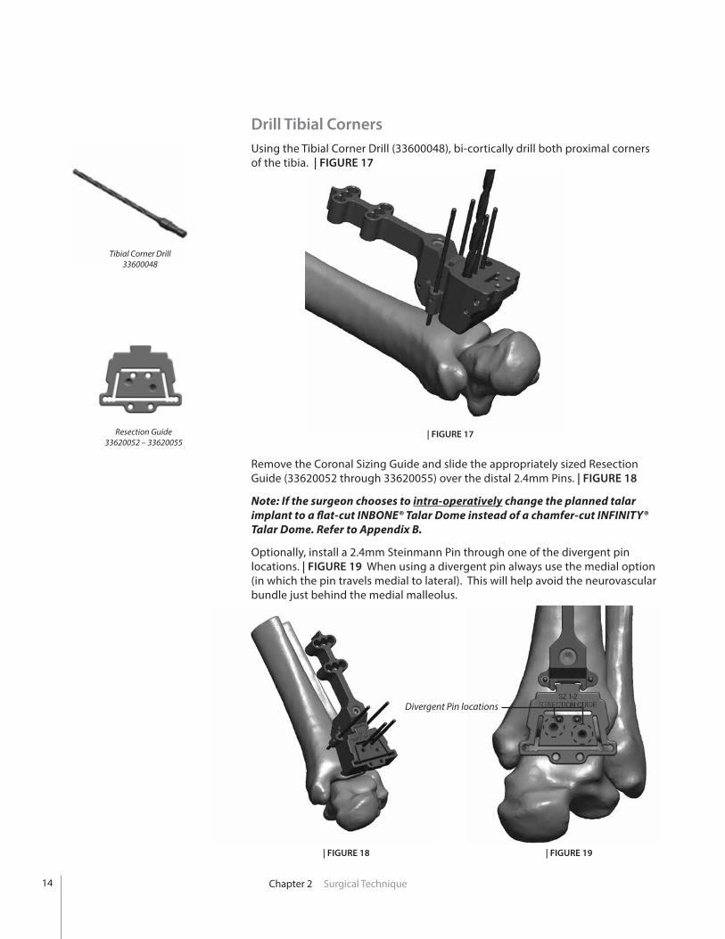
Drill Tibial Corners Using the Tibial Corner Drill (33600048), bi-cortically drill both proximal corners of the tibia. | FIGURE 17
Tibial Corner Drill33600048
Resection Guide33620052 – 33620055
| FIGURE 17
| FIGURE 18 | FIGURE 19
Divergent Pin locations
14
Remove the Coronal Sizing Guide and slide the appropriately sized Resection Guide (33620052 through 33620055) over the distal 2.4mm Pins. | FIGURE 18
Note: If the surgeon chooses to intra-operatively change the planned talar implant to a flat-cut INBONE® Talar Dome instead of a chamfer-cut INFINITY® Talar Dome. Refer to Appendix B.
Optionally, install a 2.4mm Steinmann Pin through one of the divergent pin locations. | FIGURE 19 When using a divergent pin always use the medial option (in which the pin travels medial to lateral). This will help avoid the neurovascular bundle just behind the medial malleolus.
Chapter 2 Surgical Technique
Tibial Bone Resection Using the Pin Cutter trim the Pins flush to the surface of the Resection Guide. Leave enough length on the divergent pin to allow its removal with a pin driver or pin puller but short enough to allow saw blade clearance in the medial resection slot (approximately 15mm).
Using the appropriate size Saw Blade and oscillating bone saw make the tibial resections only. This includes cutting though the proximal, medial and lateral slots of the Resection Guide.
CAUTION: Do not make the talar cut at this time.
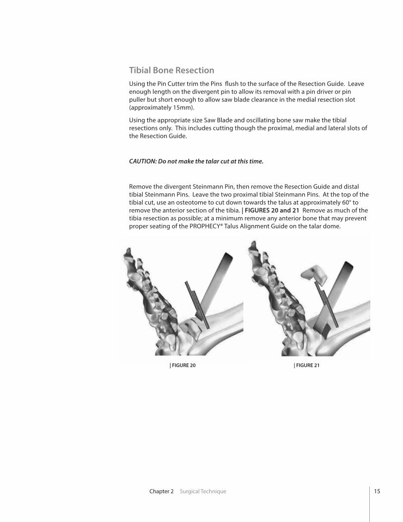
Remove the divergent Steinmann Pin, then remove the Resection Guide and distal tibial Steinmann Pins. Leave the two proximal tibial Steinmann Pins. At the top of the tibial cut, use an osteotome to cut down towards the talus at approximately 60° to remove the anterior section of the tibia. | FIGURES 20 and 21 Remove as much of the tibia resection as possible; at a minimum remove any anterior bone that may prevent proper seating of the PROPHECY® Talus Alignment Guide on the talar dome.
| FIGURE 20 | FIGURE 21
15
Chapter 2 Surgical Technique
| FIGURE 23Anterior View
Anterior Distal
| FIGURE 24Medial-Oblique View
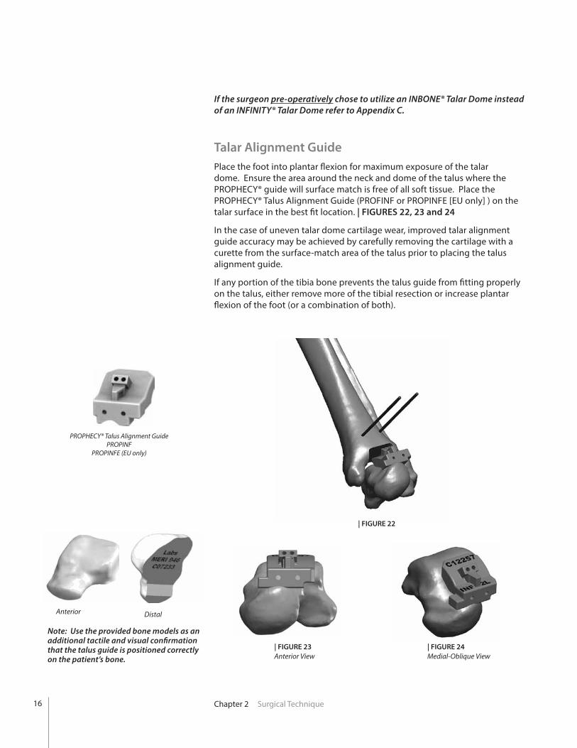
If the surgeon pre-operatively chose to utilize an INBONE® Talar Dome instead of an INFINITY® Talar Dome refer to Appendix C.
Talar Alignment Guide Place the foot into plantar flexion for maximum exposure of the talar dome. Ensure the area around the neck and dome of the talus where the PROPHECY® guide will surface match is free of all soft tissue. Place the PROPHECY® Talus Alignment Guide (PROFINF or PROPINFE [EU only] ) on the talar surface in the best fit location. | FIGURES 22, 23 and 24
In the case of uneven talar dome cartilage wear, improved talar alignment guide accuracy may be achieved by carefully removing the cartilage with a curette from the surface-match area of the talus prior to placing the talus alignment guide.
If any portion of the tibia bone prevents the talus guide from fitting properly on the talus, either remove more of the tibial resection or increase plantar flexion of the foot (or a combination of both).
PROPHECY® Talus Alignment GuidePROPINF
PROPINFE (EU only)
Note: Use the provided bone models as an additional tactile and visual confirmation that the talus guide is positioned correctly on the patient’s bone.
| FIGURE 22
16
Chapter 2 Surgical Technique
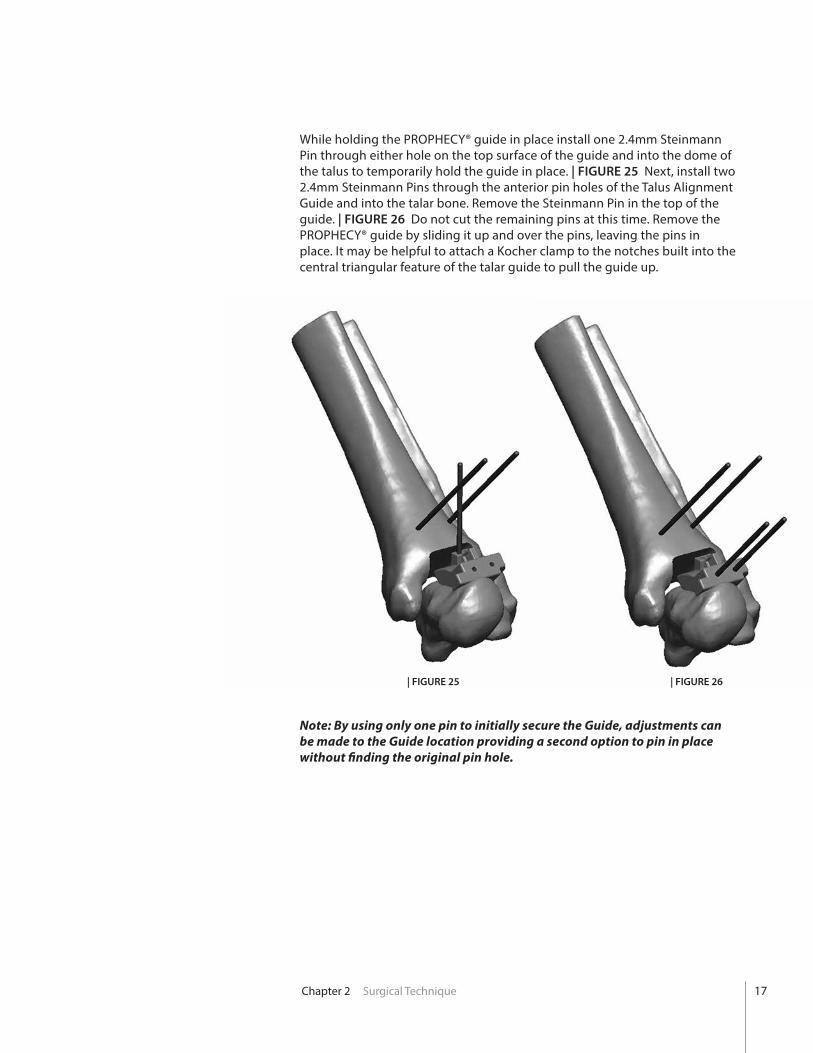
While holding the PROPHECY® guide in place install one 2.4mm Steinmann Pin through either hole on the top surface of the guide and into the dome of the talus to temporarily hold the guide in place. | FIGURE 25 Next, install two 2.4mm Steinmann Pins through the anterior pin holes of the Talus Alignment Guide and into the talar bone. Remove the Steinmann Pin in the top of the guide. | FIGURE 26 Do not cut the remaining pins at this time. Remove the PROPHECY® guide by sliding it up and over the pins, leaving the pins in place. It may be helpful to attach a Kocher clamp to the notches built into the central triangular feature of the talar guide to pull the guide up.
Note: By using only one pin to initially secure the Guide, adjustments can be made to the Guide location providing a second option to pin in place without finding the original pin hole.
| FIGURE 25 | FIGURE 26
17
Chapter 2 Surgical Technique
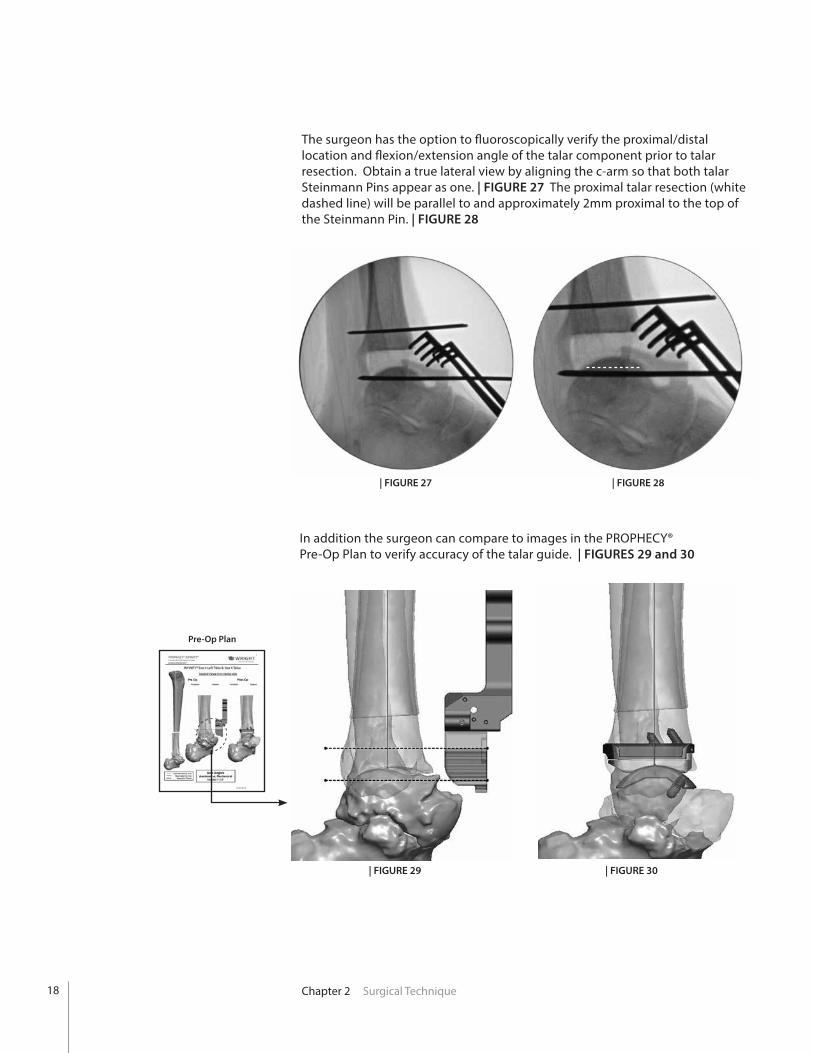
The surgeon has the option to fluoroscopically verify the proximal/distal location and flexion/extension angle of the talar component prior to talar resection. Obtain a true lateral view by aligning the c-arm so that both talar Steinmann Pins appear as one. | FIGURE 27 The proximal talar resection (white dashed line) will be parallel to and approximately 2mm proximal to the top of the Steinmann Pin. | FIGURE 28
| FIGURE 27
| FIGURE 29 | FIGURE 30
| FIGURE 28
In addition the surgeon can compare to images in the PROPHECY® Pre-Op Plan to verify accuracy of the talar guide. | FIGURES 29 and 30
18
Pre-Op Plan
Chapter 2 Surgical Technique
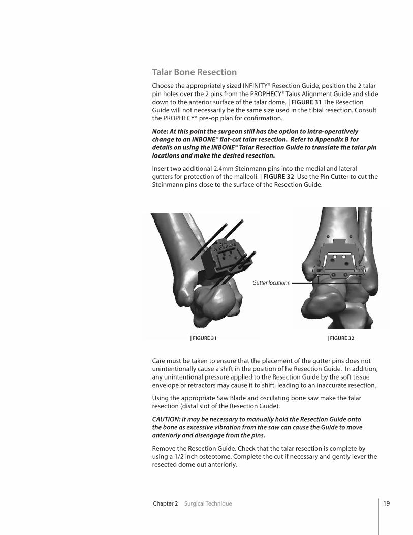
Talar Bone Resection Choose the appropriately sized INFINITY® Resection Guide, position the 2 talar pin holes over the 2 pins from the PROPHECY® Talus Alignment Guide and slide down to the anterior surface of the talar dome. | FIGURE 31 The Resection Guide will not necessarily be the same size used in the tibial resection. Consult the PROPHECY® pre-op plan for confirmation.
Note: At this point the surgeon still has the option to intra-operatively change to an INBONE® flat-cut talar resection. Refer to Appendix B for details on using the INBONE® Talar Resection Guide to translate the talar pin locations and make the desired resection.
Insert two additional 2.4mm Steinmann pins into the medial and lateral gutters for protection of the malleoli. | FIGURE 32 Use the Pin Cutter to cut the Steinmann pins close to the surface of the Resection Guide.
Care must be taken to ensure that the placement of the gutter pins does not unintentionally cause a shift in the position of he Resection Guide. In addition, any unintentional pressure applied to the Resection Guide by the soft tissue envelope or retractors may cause it to shift, leading to an inaccurate resection.
Using the appropriate Saw Blade and oscillating bone saw make the talar resection (distal slot of the Resection Guide).
CAUTION: It may be necessary to manually hold the Resection Guide onto the bone as excessive vibration from the saw can cause the Guide to move anteriorly and disengage from the pins.
Remove the Resection Guide. Check that the talar resection is complete by using a 1/2 inch osteotome. Complete the cut if necessary and gently lever the resected dome out anteriorly.
| FIGURE 31 | FIGURE 32
Gutter locations
19
Chapter 2 Surgical Technique
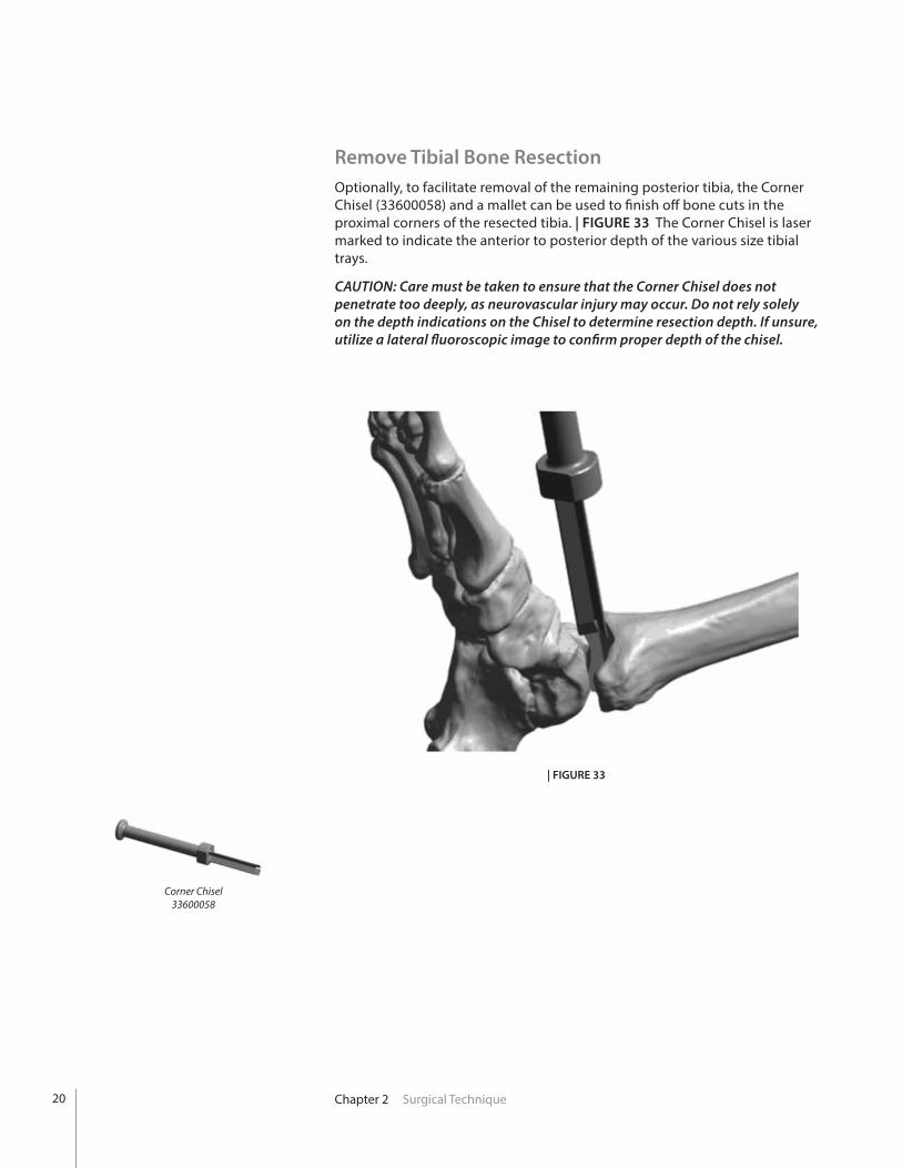
Remove Tibial Bone Resection Optionally, to facilitate removal of the remaining posterior tibia, the Corner Chisel (33600058) and a mallet can be used to finish off bone cuts in the proximal corners of the resected tibia. | FIGURE 33 The Corner Chisel is laser marked to indicate the anterior to posterior depth of the various size tibial trays.
CAUTION: Care must be taken to ensure that the Corner Chisel does not penetrate too deeply, as neurovascular injury may occur. Do not rely solely on the depth indications on the Chisel to determine resection depth. If unsure, utilize a lateral fluoroscopic image to confirm proper depth of the chisel.
| FIGURE 33
Corner Chisel33600058
20
Chapter 2 Surgical Technique
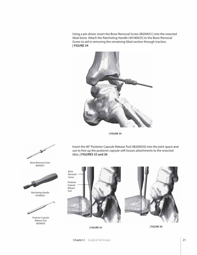
Using a pin driver, insert the Bone Removal Screw (IB200051) into the resected tibial bone. Attach the Ratcheting Handle (44180025) to the Bone Removal Screw to aid in removing the remaining tibial section through traction. | FIGURE 34
Bone Removal ScrewIB200051
BoneRemovalScrew
| FIGURE 34
Ratcheting Handle44180025
Posterior Capsule Release Tool
IB200050
PosteriorCapsule ReleaseTool
Insert the 90° Posterior Capsule Release Tool (IB200050) into the joint space and use to free up the posterior capsule soft tissues attachments to the resected tibia. | FIGURES 35 and 36
| FIGURE 35 | FIGURE 36
21
Chapter 2 Surgical Technique
| FIGURE 37
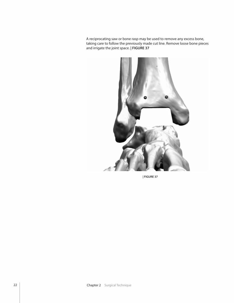
A reciprocating saw or bone rasp may be used to remove any excess bone, taking care to follow the previously made cut line. Remove loose bone pieces and irrigate the joint space. | FIGURE 37
22
Chapter 2 Surgical Technique
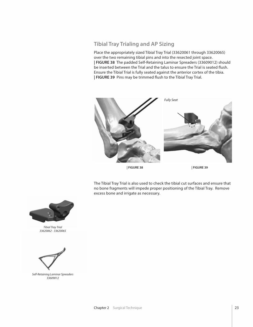
Tibial Tray Trialing and AP Sizing Place the appropriately sized Tibial Tray Trial (33620061 through 33620065) over the two remaining tibial pins and into the resected joint space. | FIGURE 38 The padded Self-Retaining Laminar Spreaders (33609012) should be inserted between the Trial and the talus to ensure the Trial is seated flush. Ensure the Tibial Trial is fully seated against the anterior cortex of the tibia. | FIGURE 39 Pins may be trimmed flush to the Tibial Tray Trial.
The Tibial Tray Trial is also used to check the tibial cut surfaces and ensure that no bone fragments will impede proper positioning of the Tibial Tray. Remove excess bone and irrigate as necessary.
| FIGURE 38 | FIGURE 39
Fully Seat
Tibial Tray Trial33620062 - 33620065
Self-Retaining Laminar Spreaders33609012
23
Chapter 2 Surgical Technique
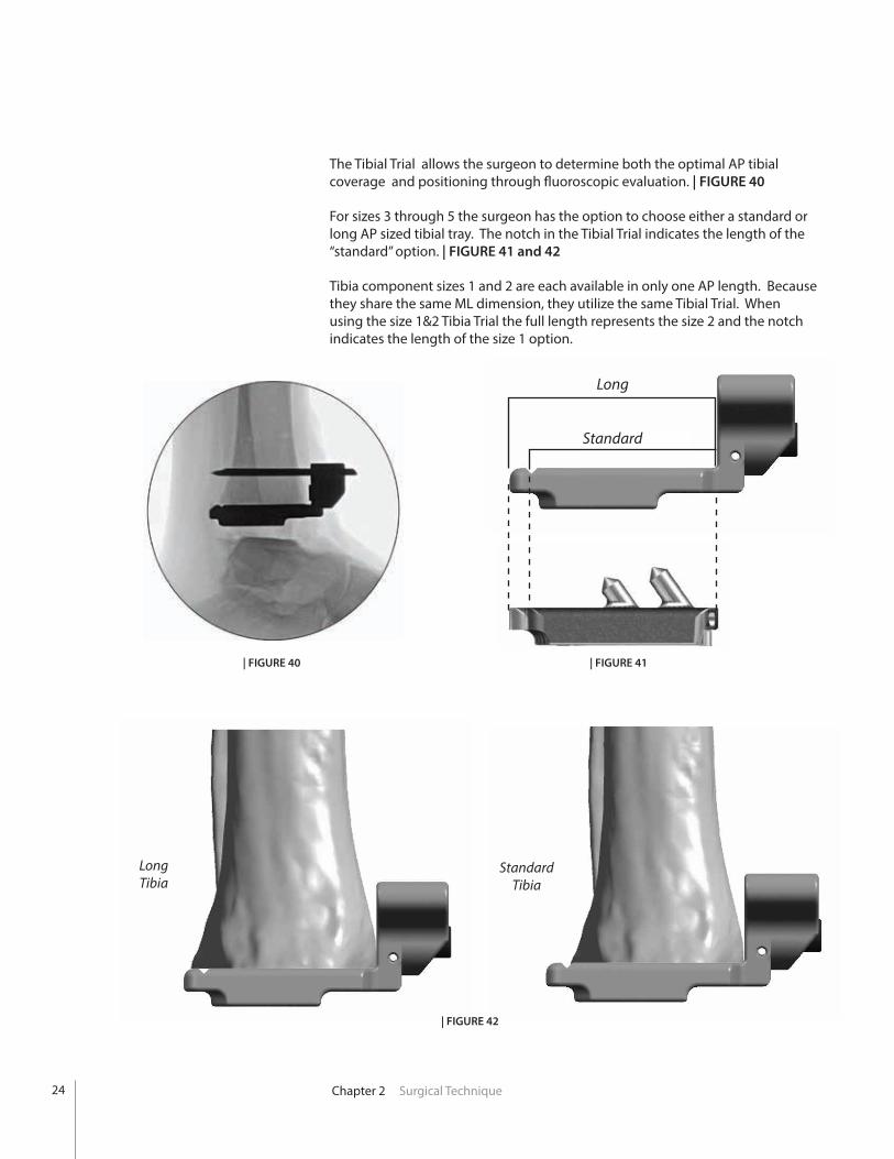
The Tibial Trial allows the surgeon to determine both the optimal AP tibial coverage and positioning through fluoroscopic evaluation. | FIGURE 40
For sizes 3 through 5 the surgeon has the option to choose either a standard or long AP sized tibial tray. The notch in the Tibial Trial indicates the length of the “standard” option. | FIGURE 41 and 42
Tibia component sizes 1 and 2 are each available in only one AP length. Because they share the same ML dimension, they utilize the same Tibial Trial. When using the size 1&2 Tibia Trial the full length represents the size 2 and the notch indicates the length of the size 1 option.
| FIGURE 41| FIGURE 40
Long
Standard
| FIGURE 42
LongTibia
StandardTibia
24
Chapter 2 Surgical Technique
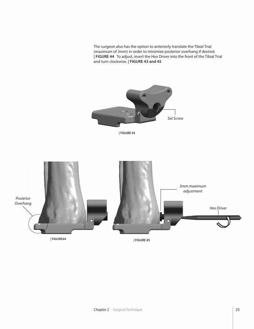
The surgeon also has the option to anteriorly translate the Tibial Trial (maximum of 3mm) in order to minimize posterior overhang if desired. | FIGURE 44 To adjust, insert the Hex Driver into the front of the Tibial Trial and turn clockwise. | FIGURE 43 and 45
Set Screw
| FIGURE44
| FIGURE 43
| FIGURE 45
3mm maximum adjustment
Posterior Overhang
Hex Driver
25
Chapter 2 Surgical Technique
Tibial Peg Broaching
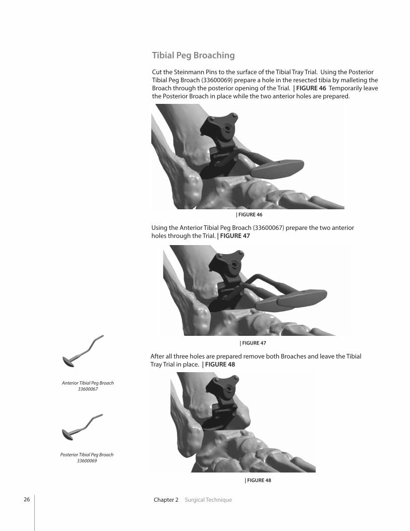
Cut the Steinmann Pins to the surface of the Tibial Tray Trial. Using the Posterior Tibial Peg Broach (33600069) prepare a hole in the resected tibia by malleting the Broach through the posterior opening of the Trial. | FIGURE 46 Temporarily leave the Posterior Broach in place while the two anterior holes are prepared.
| FIGURE 46
Using the Anterior Tibial Peg Broach (33600067) prepare the two anterior holes through the Trial. | FIGURE 47
| FIGURE 47
Posterior Tibial Peg Broach33600069
Anterior Tibial Peg Broach33600067
After all three holes are prepared remove both Broaches and leave the Tibial Tray Trial in place. | FIGURE 48
| FIGURE 48
26
Chapter 2 Surgical Technique
Talar Component Sizing and Positioning
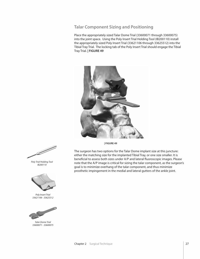
Place the appropriately sized Talar Dome Trial (33600071 through 33600075) into the joint space. Using the Poly Insert Trial Holding Tool (IB200110) install the appropriately sized Poly Insert Trial (33621106 through 33625512) into the Tibial Tray Trial. The locking tab of the Poly Insert Trial should engage the Tibial Tray Trial. | FIGURE 49
| FIGURE 49
The surgeon has two options for the Talar Dome implant size at this juncture: either the matching size for the implanted Tibial Tray, or one size smaller. It is beneficial to assess both sizes under A/P and lateral fluoroscopic images. Please note that the A/P image is critical for sizing the talar component, as the surgeon’s goal is to minimize overhang of the talar component, and thus minimize prosthetic impingement in the medial and lateral gutters of the ankle joint.
Talar Dome Trial33600071 - 33600075
Poly Insert Trial33621106 - 33625512
Poly Trial Holding ToolIB200110
27
Chapter 2 Surgical Technique
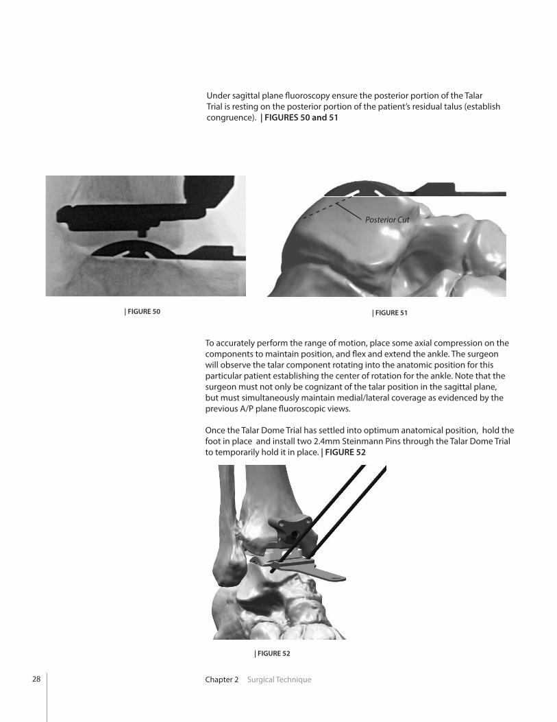
Under sagittal plane fluoroscopy ensure the posterior portion of the Talar Trial is resting on the posterior portion of the patient’s residual talus (establish congruence). | FIGURES 50 and 51
| FIGURE 51
To accurately perform the range of motion, place some axial compression on the components to maintain position, and flex and extend the ankle. The surgeon will observe the talar component rotating into the anatomic position for this particular patient establishing the center of rotation for the ankle. Note that the surgeon must not only be cognizant of the talar position in the sagittal plane, but must simultaneously maintain medial/lateral coverage as evidenced by the previous A/P plane fluoroscopic views.
Once the Talar Dome Trial has settled into optimum anatomical position, hold the foot in place and install two 2.4mm Steinmann Pins through the Talar Dome Trial to temporarily hold it in place. | FIGURE 52
| FIGURE 50
| FIGURE 52
Posterior Cut
28
Chapter 2 Surgical Technique
Talar Chamfer Resections
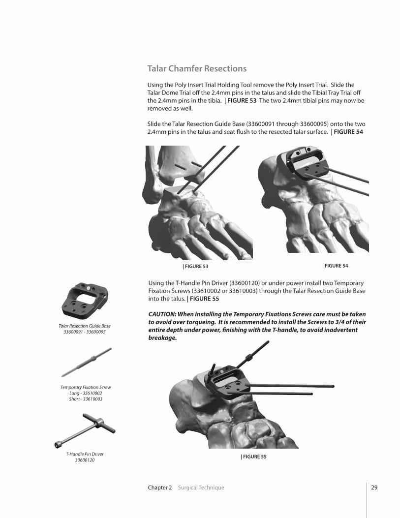
Using the Poly Insert Trial Holding Tool remove the Poly Insert Trial. Slide the Talar Dome Trial off the 2.4mm pins in the talus and slide the Tibial Tray Trial off the 2.4mm pins in the tibia. | FIGURE 53 The two 2.4mm tibial pins may now be removed as well.
Slide the Talar Resection Guide Base (33600091 through 33600095) onto the two 2.4mm pins in the talus and seat flush to the resected talar surface. | FIGURE 54
| FIGURE 53 | FIGURE 54
Using the T-Handle Pin Driver (33600120) or under power install two Temporary Fixation Screws (33610002 or 33610003) through the Talar Resection Guide Base into the talus. | FIGURE 55
CAUTION: When installing the Temporary Fixations Screws care must be taken to avoid over torqueing. It is recommended to install the Screws to 3/4 of their entire depth under power, finishing with the T-handle, to avoid inadvertent breakage.
| FIGURE 55T-Handle Pin Driver33600120
Temporary Fixation ScrewLong - 33610002 Short - 33610003
Talar Resection Guide Base33600091 - 33600095
29

Chapter 2 Surgical Technique
Using the appropriately sized Saw Blade and oscillating or reciprocating bone saw make the posterior talar chamfer resection through the slot in the Talar Resection Guide Base. | FIGURE 56
Remove the two anterior 2.4mm Pins. One of these pins can then be installed through the anterior pin hole in the Guide Base to provide additional fixation during the talar preparation steps. Cut this pin flush to the surface of the Guide Base to prevent interference with the saw blades and reamers. | FIGURE 57
| FIGURE 56
| FIGURE 57
Steinmann Pin
30
Chapter 2 Surgical Technique
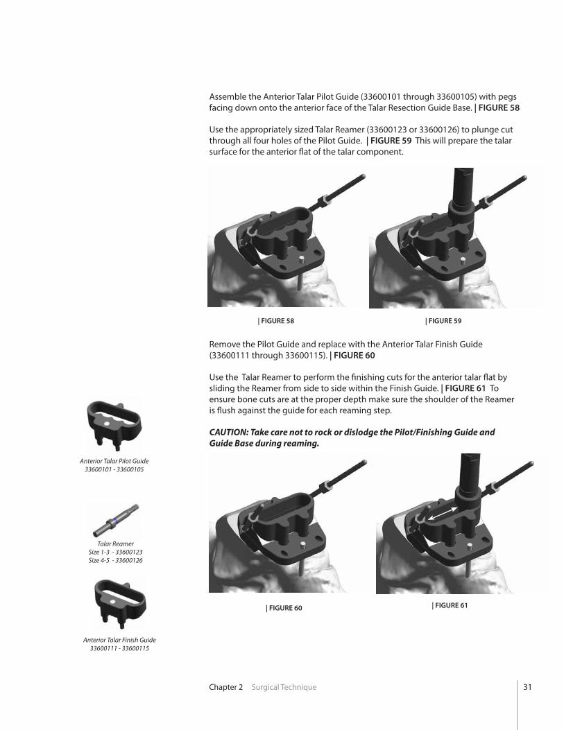
Assemble the Anterior Talar Pilot Guide (33600101 through 33600105) with pegs facing down onto the anterior face of the Talar Resection Guide Base. | FIGURE 58
Use the appropriately sized Talar Reamer (33600123 or 33600126) to plunge cut through all four holes of the Pilot Guide. | FIGURE 59 This will prepare the talar surface for the anterior flat of the talar component.
| FIGURE 58 | FIGURE 59
Remove the Pilot Guide and replace with the Anterior Talar Finish Guide (33600111 through 33600115). | FIGURE 60
Use the Talar Reamer to perform the finishing cuts for the anterior talar flat by sliding the Reamer from side to side within the Finish Guide. | FIGURE 61 To ensure bone cuts are at the proper depth make sure the shoulder of the Reamer is flush against the guide for each reaming step.
CAUTION: Take care not to rock or dislodge the Pilot/Finishing Guide and Guide Base during reaming.
| FIGURE 60 | FIGURE 61
Anterior Talar Finish Guide33600111 - 33600115
Anterior Talar Pilot Guide33600101 - 33600105
Talar ReamerSize 1-3 - 33600123 Size 4-5 - 33600126
31
Chapter 2 Surgical Technique
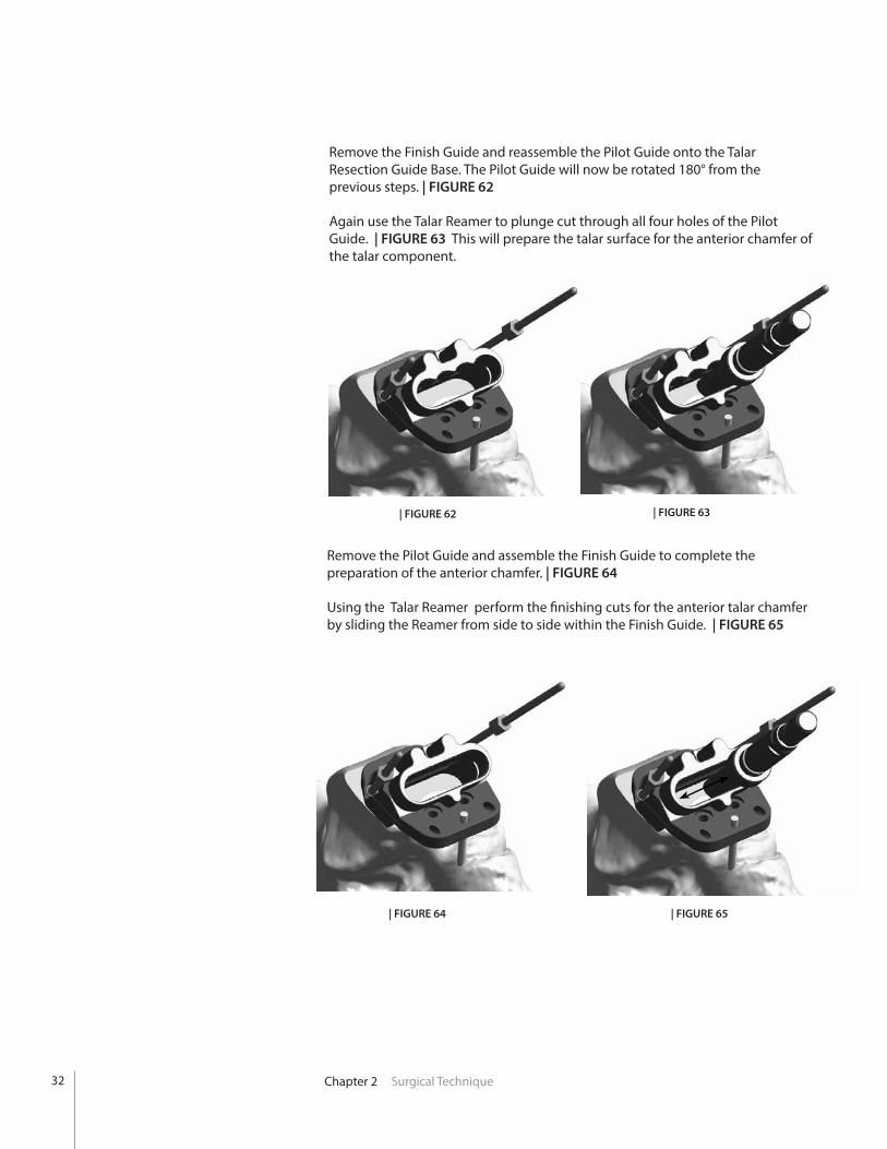
Remove the Finish Guide and reassemble the Pilot Guide onto the Talar Resection Guide Base. The Pilot Guide will now be rotated 180° from the previous steps. | FIGURE 62
Again use the Talar Reamer to plunge cut through all four holes of the Pilot Guide. | FIGURE 63 This will prepare the talar surface for the anterior chamfer of the talar component.
Remove the Pilot Guide and assemble the Finish Guide to complete the preparation of the anterior chamfer. | FIGURE 64
Using the Talar Reamer perform the finishing cuts for the anterior talar chamfer by sliding the Reamer from side to side within the Finish Guide. | FIGURE 65
| FIGURE 62 | FIGURE 63
| FIGURE 64 | FIGURE 65
32

Chapter 2 Surgical Technique
Remove the Fixation Pins and Resection Guide Base and remove any residual bone medial and lateral to the prepared chamfer cuts using either an osteotome or rongeur. | FIGURE 66
CAUTION: Failure to adequately remove residual bone from resected edges may lead to improper seating of the talar component.
| FIGURE 66
Polyethylene Thickness
While the final polyethylene thickness does not have to be definitively chosen during the trial phase, it is important to have what is perceived to be the appropriately sized trial poly to accurately determine the placement of the talar component. The trial poly used for the reduction should fit appropriately to determine the center of rotation of the talar component; therefore, trialing multiple size polys may be necessary. Note that after insertion of the final talar dome, the height of the poly can and should be reassessed.
In order to determine proper polyethylene height the following factors must be considered:
Smooth range of motion of the ankle without anterior or posterior impingement.
Ligaments are tensioned both medially and laterally WITHOUT over-tensioning. Over-tensioning is noted when the trial talar component tilts following trial poly insertion. Alternatively, with range of motion, the talar component becomes incongruent with the trial poly, which can identify too much tension on the ankle replacement. Over-tensioned joints may cause increased polyethylene wear, and should be avoided.
Stress the ankle joint into varus and valgus. The trial components should not tilt.
The trial poly should engage the sulcus in the talar dome trial without allowing medial/lateral translation.
33
Chapter 2 Surgical Technique
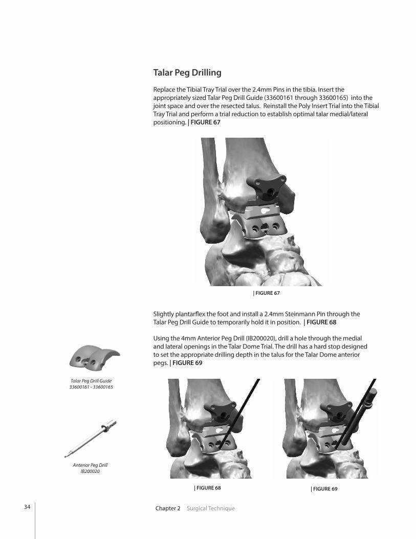
Talar Peg Drilling
Replace the Tibial Tray Trial over the 2.4mm Pins in the tibia. Insert the appropriately sized Talar Peg Drill Guide (33600161 through 33600165) into the joint space and over the resected talus. Reinstall the Poly Insert Trial into the Tibial Tray Trial and perform a trial reduction to establish optimal talar medial/lateral positioning. | FIGURE 67
| FIGURE 67
Slightly plantarflex the foot and install a 2.4mm Steinmann Pin through the Talar Peg Drill Guide to temporarily hold it in position. | FIGURE 68
Using the 4mm Anterior Peg Drill (IB200020), drill a hole through the medial and lateral openings in the Talar Dome Trial. The drill has a hard stop designed to set the appropriate drilling depth in the talus for the Talar Dome anterior pegs. | FIGURE 69
| FIGURE 68 | FIGURE 69
Anterior Peg DrillIB200020
Talar Peg Drill Guide33600161 - 33600165
34
Chapter 2 Surgical Technique
Tibial Component Implantation
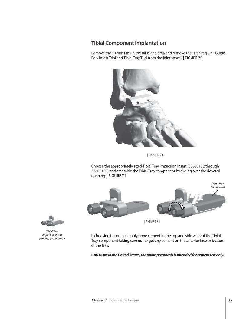
Remove the 2.4mm Pins in the talus and tibia and remove the Talar Peg Drill Guide, Poly Insert Trial and Tibial Tray Trial from the joint space. | FIGURE 70
Choose the appropriately sized Tibial Tray Impaction Insert (33600132 through 33600135) and assemble the Tibial Tray component by sliding over the dovetail opening. | FIGURE 71
If choosing to cement, apply bone cement to the top and side walls of the Tibial Tray component taking care not to get any cement on the anterior face or bottom of the Tray.
CAUTION: In the United States, the ankle prosthesis is intended for cement use only.
| FIGURE 71
| FIGURE 70
Tibial Tray Impaction Insert
33600132 - 33600135
35
Tibial Tray Component
Chapter 2 Surgical Technique
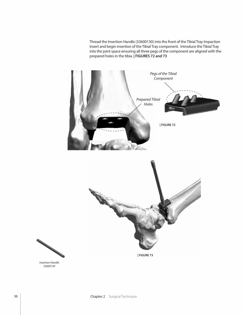
Thread the Insertion Handle (33600130) into the front of the Tibial Tray Impaction Insert and begin insertion of the Tibial Tray component. Introduce the Tibial Tray into the joint space ensuring all three pegs of the component are aligned with the prepared holes in the tibia. | FIGURES 72 and 73
| FIGURE 72
| FIGURE 73
Insertion Handle33600130
Pegs of the Tibial Component
Prepared Tibial Holes
36
Chapter 2 Surgical Technique
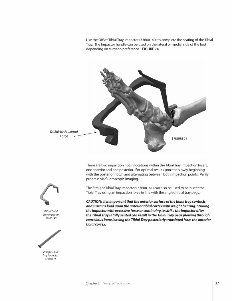
Use the Offset Tibial Tray Impactor (33600140) to complete the seating of the Tibial Tray. The Impactor handle can be used on the lateral or medial side of the foot depending on surgeon preference. | FIGURE 74
There are two impaction notch locations within the Tibial Tray Impaction Insert, one anterior and one posterior. For optimal results proceed slowly beginning with the posterior notch and alternating between both impaction points. Verify progress via fluoroscopic imaging.
The Straight Tibial Tray Impactor (33600141) can also be used to help seat the Tibial Tray using an impaction force in line with the angled tibial tray pegs.
CAUTION: It is important that the anterior surface of the tibial tray contacts and sustains load upon the anterior tibial cortex with weight bearing. Striking the Impactor with excessive force or continuing to strike the Impactor after the Tibial Tray is fully seated can result in the Tibial Tray pegs plowing through cancellous bone leaving the Tibial Tray posteriorly translated from the anterior tibial cortex.
Distal-to-Proximal Force
| FIGURE 74
Straight Tibial Tray Impactor
33600141
Offset Tibial Tray Impactor
33600140
37
Chapter 2 Surgical Technique
Talar Component Implantation
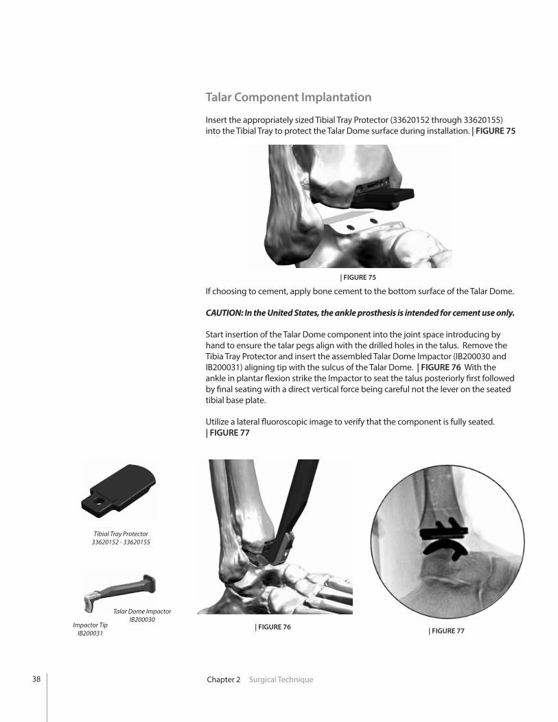
Insert the appropriately sized Tibial Tray Protector (33620152 through 33620155) into the Tibial Tray to protect the Talar Dome surface during installation. | FIGURE 75
Tibial Tray Protector33620152 - 33620155
| FIGURE 75
If choosing to cement, apply bone cement to the bottom surface of the Talar Dome.
CAUTION: In the United States, the ankle prosthesis is intended for cement use only.
Start insertion of the Talar Dome component into the joint space introducing by hand to ensure the talar pegs align with the drilled holes in the talus. Remove the Tibia Tray Protector and insert the assembled Talar Dome Impactor (IB200030 and IB200031) aligning tip with the sulcus of the Talar Dome. | FIGURE 76 With the ankle in plantar flexion strike the Impactor to seat the talus posteriorly first followed by final seating with a direct vertical force being careful not the lever on the seated tibial base plate.
Utilize a lateral fluoroscopic image to verify that the component is fully seated. | FIGURE 77
| FIGURE 76
Talar Dome ImpactorIB200030
Impactor TipIB200031 | FIGURE 77
38
Chapter 2 Surgical Technique
Polyethylene Bearing Installation
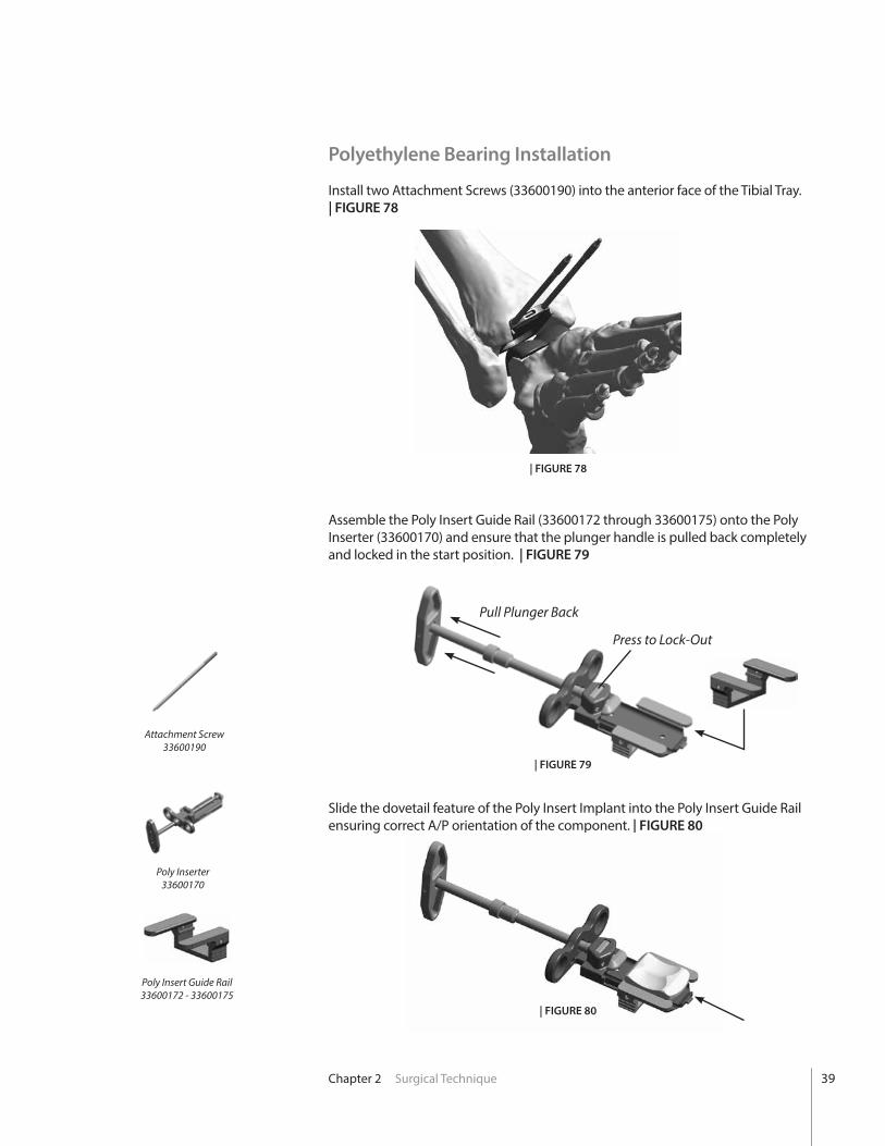
Install two Attachment Screws (33600190) into the anterior face of the Tibial Tray. | FIGURE 78
Assemble the Poly Insert Guide Rail (33600172 through 33600175) onto the Poly Inserter (33600170) and ensure that the plunger handle is pulled back completely and locked in the start position. | FIGURE 79
Slide the dovetail feature of the Poly Insert Implant into the Poly Insert Guide Rail ensuring correct A/P orientation of the component. | FIGURE 80
| FIGURE 78
| FIGURE 79
Attachment Screw 33600190
Poly Inserter33600170
Poly Insert Guide Rail33600172 - 33600175
Press to Lock-Out
Pull Plunger Back
| FIGURE 80
39

Chapter 2 Surgical Technique
Slide the Poly Inserter Assembly over the Attachment Screws and flush to the surface of the Tibial Tray. Thread an Attachment Nut (33600191) over the end of each Attachment Screw to tightly secure the Poly Inserter in place. | FIGURE 81
| FIGURE 81
Attachment Nut 33600191
CAUTION: Properly irrigate prior to poly insertion. It is important to remove any fragments of bone or soft tissue from the lock detail on the tibial tray to insure that the polyethylene will seat completely within the tibial tray lock detail.
40
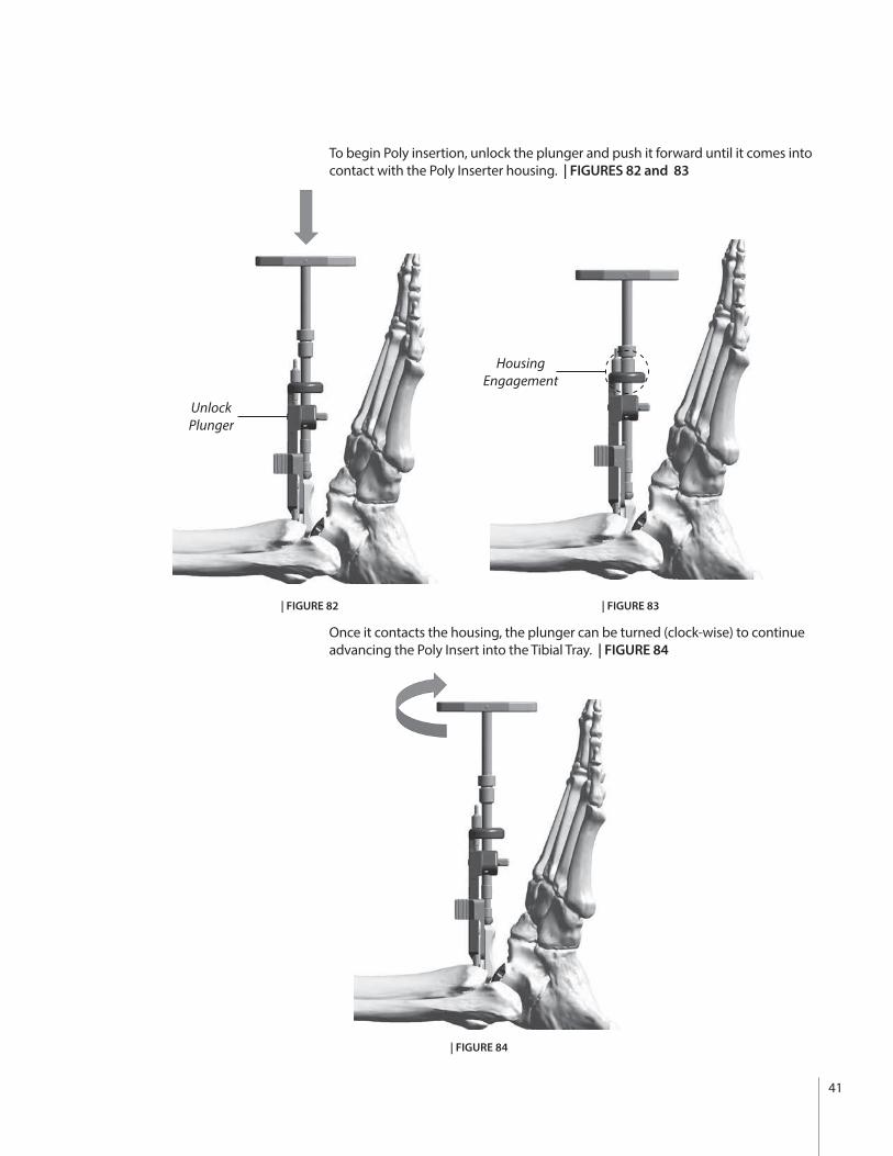
To begin Poly insertion, unlock the plunger and push it forward until it comes into contact with the Poly Inserter housing. | FIGURES 82 and 83
Once it contacts the housing, the plunger can be turned (clock-wise) to continue advancing the Poly Insert into the Tibial Tray. | FIGURE 84
Housing Engagement
| FIGURE 82 | FIGURE 83
| FIGURE 84
Unlock Plunger
41

Chapter 2 Surgical Technique
After the plunger has reached maximum depth unthread the two Attachment Nuts, remove the Poly Inserter housing and unthread the two Attachment Screws from the tibial tray. | FIGURE 85
| FIGURE 85
42
Chapter 2 Surgical Technique
In some cases the poly may not fully seat using the insertion tool. In these rare cases only, line up the tip of the Straight Tibial Tray Impactor (33600141) with the groove in the anterior face of the poly insert. Angle the Impactor slightly and use a gentle distal to proximal mallet strike to complete the seating.
CAUTION: Striking the Impactor with excessive force can result in the Tibial Tray pegs plowing through cancellous bone leaving the tibial tray posteriorly translated from the anterior tibia cortex.
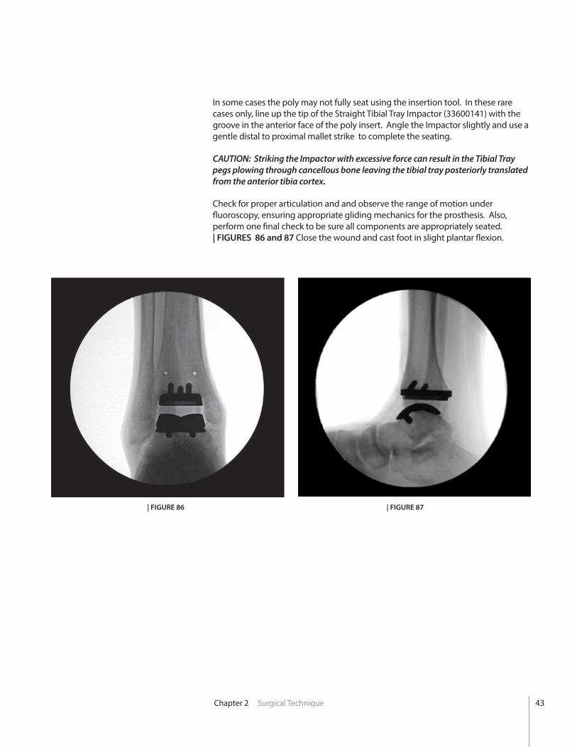
Check for proper articulation and and observe the range of motion under fluoroscopy, ensuring appropriate gliding mechanics for the prosthesis. Also, perform one final check to be sure all components are appropriately seated. | FIGURES 86 and 87 Close the wound and cast foot in slight plantar flexion.
| FIGURE 86 | FIGURE 87
43

Explant Information
INSERT REPLACEMENT
The Poly Insert has a pre-drilled hole feature on the anterior face. To remove the Poly Insert, first use a pin driver to install the Bone Removal Screw through the pre-drilled hole. Attached the Ratcheting Handle and pull distally on the Removal Screw in an attempt to unlock the Insert from the Tibial Tray. A narrow osteotome may be inserted into the anterior region of the insert to facilitate removal. A hemostat may be used to remove the insert once it is no longer locked to the tibial tray. Care must be taken not to scratch or damage any component that is not intended to be removed.
TIBIA AND TALAR COMPONENTS
To remove the components, small osteotomes, power saws, or other surgical instruments may be used to disrupt the bone-cement interface. Care must be exhibited to save remaining bone stock as well as to prevent fracture. Once the components have been removed, rongeurs or small osteotomes as well as other surgical instruments may be used to remove the remaining cement.
If the removal of the implant is required due to revision or failure of the device, the surgeon should contact the manufacturer using the contact information located on the back cover of this surgical technique to receive instructions for returning the explanted device to the manufacturer for investigation.
Postoperative Management
Postoperative care is the responsibility of the medical professional.
44
App
endi
x A
Conversion toStandard Instrumentation
Appendix A Conversion to Standard Instrumentation
Prior to making the tibial resection, the following modifications can be made:
• Medial-Lateral Position of Tibial Resection
• Proximal-Distal Level of Tibial Resection
• Tibial Implant Size
CAUTION: In order to adjust the sagittal, coronal or axial rotation of the tibial resection, the surgeon must revert back to the standard INFINTIY® surgical technique. Refer to technique number 010395.
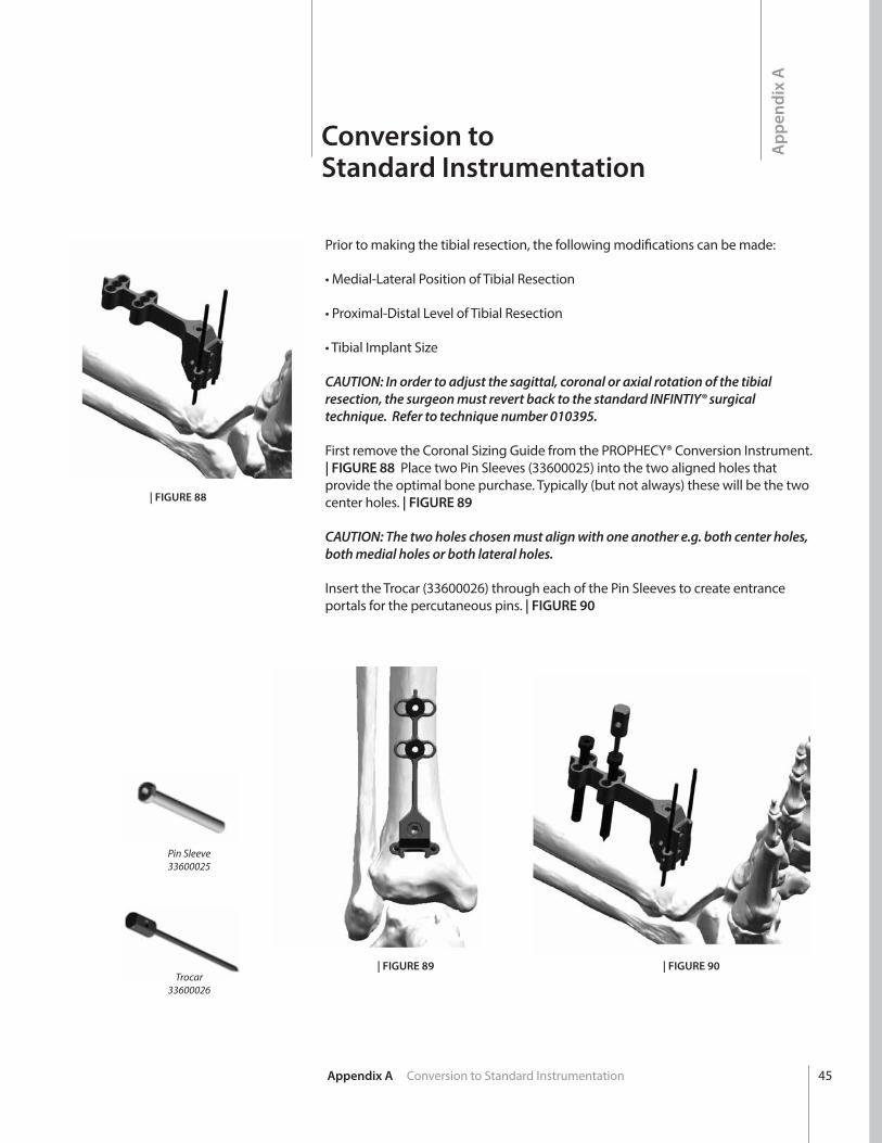
First remove the Coronal Sizing Guide from the PROPHECY® Conversion Instrument. | FIGURE 88 Place two Pin Sleeves (33600025) into the two aligned holes that provide the optimal bone purchase. Typically (but not always) these will be the two center holes. | FIGURE 89
CAUTION: The two holes chosen must align with one another e.g. both center holes, both medial holes or both lateral holes.
Insert the Trocar (33600026) through each of the Pin Sleeves to create entrance portals for the percutaneous pins. | FIGURE 90
| FIGURE 88
| FIGURE 89 | FIGURE 90
Pin Sleeve33600025
Trocar33600026
45
Appendix A Conversion to Standard Instrumentation
Install Sizing and Resection Guide Adjustment Block
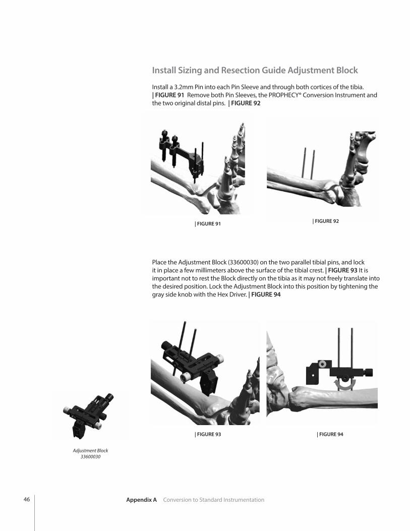
Install a 3.2mm Pin into each Pin Sleeve and through both cortices of the tibia. | FIGURE 91 Remove both Pin Sleeves, the PROPHECY® Conversion Instrument and the two original distal pins. | FIGURE 92
Place the Adjustment Block (33600030) on the two parallel tibial pins, and lock it in place a few millimeters above the surface of the tibial crest. | FIGURE 93 It is important not to rest the Block directly on the tibia as it may not freely translate into the desired position. Lock the Adjustment Block into this position by tightening the gray side knob with the Hex Driver. | FIGURE 94
| FIGURE 91
| FIGURE 93 | FIGURE 94
| FIGURE 92
Adjustment Block33600030
46
Coronal Plane Sizing and Positioning
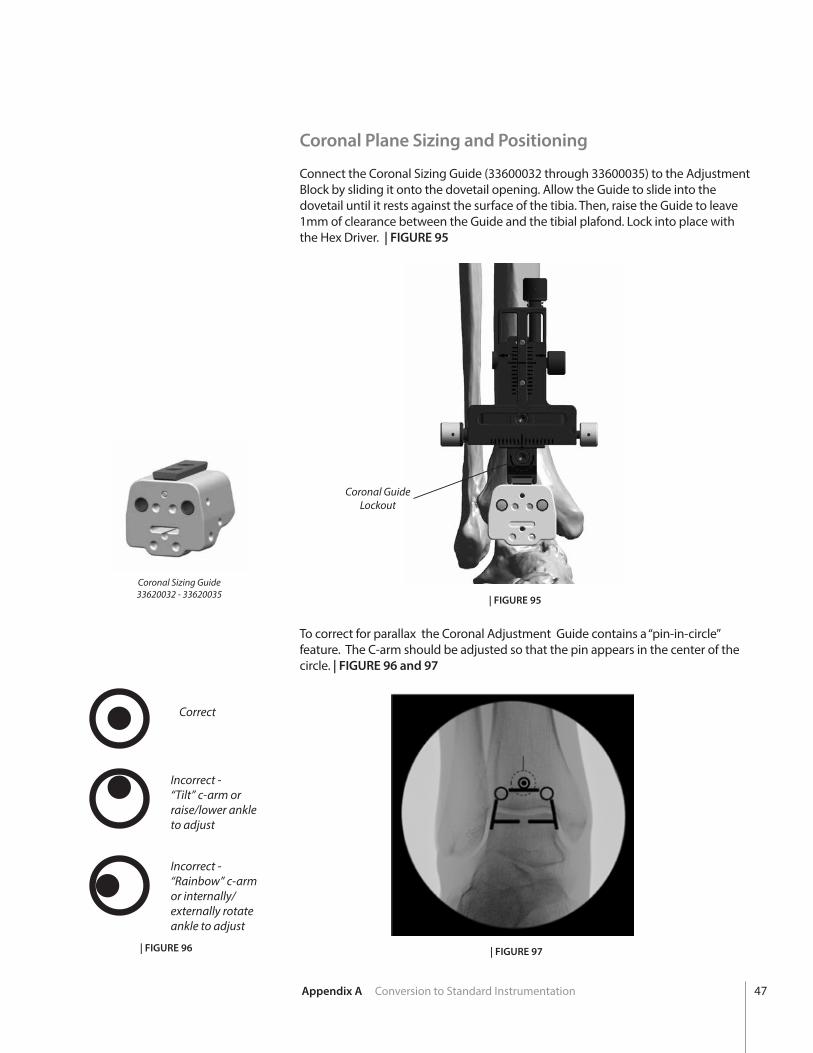
Connect the Coronal Sizing Guide (33600032 through 33600035) to the Adjustment Block by sliding it onto the dovetail opening. Allow the Guide to slide into the dovetail until it rests against the surface of the tibia. Then, raise the Guide to leave 1mm of clearance between the Guide and the tibial plafond. Lock into place with the Hex Driver. | FIGURE 95
To correct for parallax the Coronal Adjustment Guide contains a “pin-in-circle” feature. The C-arm should be adjusted so that the pin appears in the center of the circle. | FIGURE 96 and 97
Coronal Sizing Guide33620032 - 33620035
Coronal GuideLockout
| FIGURE 96 | FIGURE 97
| FIGURE 95
Appendix A Conversion to Standard Instrumentation
Correct
Incorrect -“Tilt” c-arm or raise/lower ankle to adjust
Incorrect -“Rainbow” c-armor internally/externally rotate ankle to adjust
47
| FIGURE 98
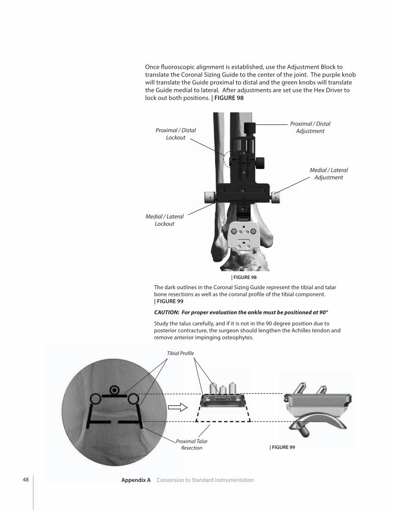
Medial / Lateral Adjustment
Medial / Lateral Lockout
Proximal / DistalLockout
Proximal / DistalAdjustment
The dark outlines in the Coronal Sizing Guide represent the tibial and talar bone resections as well as the coronal profile of the tibial component. | FIGURE 99
CAUTION: For proper evaluation the ankle must be positioned at 90°
Study the talus carefully, and if it is not in the 90 degree position due to posterior contracture, the surgeon should lengthen the Achilles tendon and remove anterior impinging osteophytes.
Tibial Profile
Proximal Talar Resection | FIGURE 99
Appendix A Conversion to Standard Instrumentation
Once fluoroscopic alignment is established, use the Adjustment Block to translate the Coronal Sizing Guide to the center of the joint. The purple knob will translate the Guide proximal to distal and the green knobs will translate the Guide medial to lateral. After adjustments are set use the Hex Driver to lock out both positions. | FIGURE 98
48
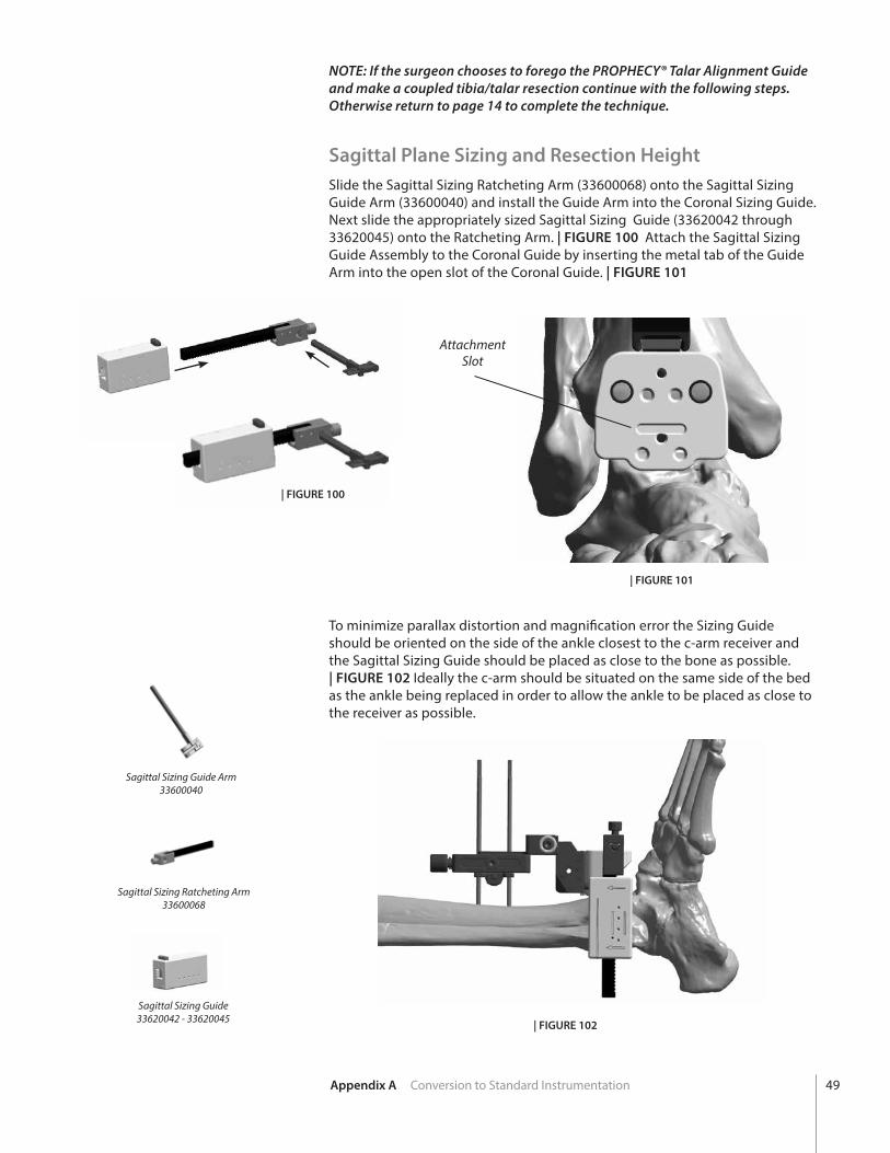
Sagittal Plane Sizing and Resection Height Slide the Sagittal Sizing Ratcheting Arm (33600068) onto the Sagittal Sizing Guide Arm (33600040) and install the Guide Arm into the Coronal Sizing Guide. Next slide the appropriately sized Sagittal Sizing Guide (33620042 through 33620045) onto the Ratcheting Arm. | FIGURE 100 Attach the Sagittal Sizing Guide Assembly to the Coronal Guide by inserting the metal tab of the Guide Arm into the open slot of the Coronal Guide. | FIGURE 101
Attachment Slot
| FIGURE 100
| FIGURE 101
To minimize parallax distortion and magnification error the Sizing Guide should be oriented on the side of the ankle closest to the c-arm receiver and the Sagittal Sizing Guide should be placed as close to the bone as possible. | FIGURE 102 Ideally the c-arm should be situated on the same side of the bed as the ankle being replaced in order to allow the ankle to be placed as close to the receiver as possible.
NOTE: If the surgeon chooses to forego the PROPHECY® Talar Alignment Guide and make a coupled tibia/talar resection continue with the following steps. Otherwise return to page 14 to complete the technique.
Sagittal Sizing Guide Arm33600040
Sagittal Sizing Ratcheting Arm33600068
Sagittal Sizing Guide33620042 - 33620045 | FIGURE 102
Appendix A Conversion to Standard Instrumentation 49
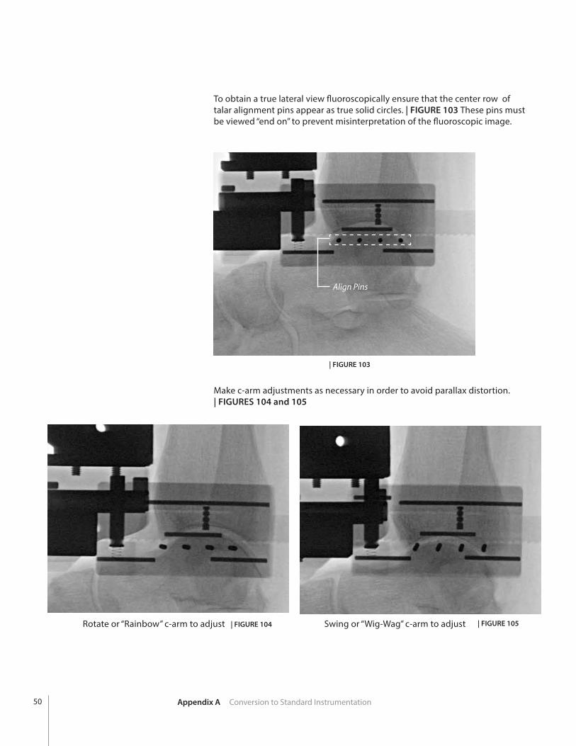
To obtain a true lateral view fluoroscopically ensure that the center row of talar alignment pins appear as true solid circles. | FIGURE 103 These pins must be viewed “end on” to prevent misinterpretation of the fluoroscopic image.
| FIGURE 103
Align Pins
| FIGURE 104 | FIGURE 105
Make c-arm adjustments as necessary in order to avoid parallax distortion. | FIGURES 104 and 105
Rotate or “Rainbow” c-arm to adjust Swing or “Wig-Wag” c-arm to adjust
Appendix A Conversion to Standard Instrumentation50
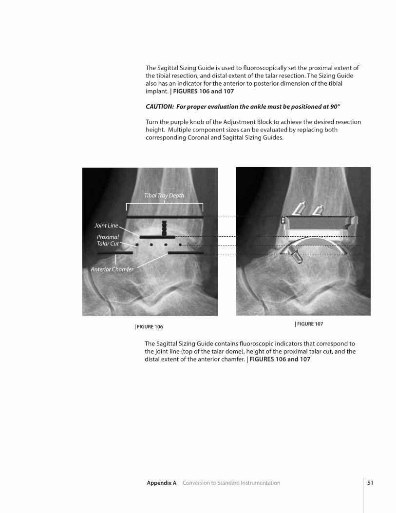
The Sagittal Sizing Guide is used to fluoroscopically set the proximal extent of the tibial resection, and distal extent of the talar resection. The Sizing Guide also has an indicator for the anterior to posterior dimension of the tibial implant. | FIGURES 106 and 107
CAUTION: For proper evaluation the ankle must be positioned at 90°
Turn the purple knob of the Adjustment Block to achieve the desired resection height. Multiple component sizes can be evaluated by replacing both corresponding Coronal and Sagittal Sizing Guides.
The Sagittal Sizing Guide contains fluoroscopic indicators that correspond to the joint line (top of the talar dome), height of the proximal talar cut, and the distal extent of the anterior chamfer. | FIGURES 106 and 107
| FIGURE 106 | FIGURE 107
Anterior Chamfer
Tibal Tray Depth
ProximalTalar Cut
Joint Line
Appendix A Conversion to Standard Instrumentation 51
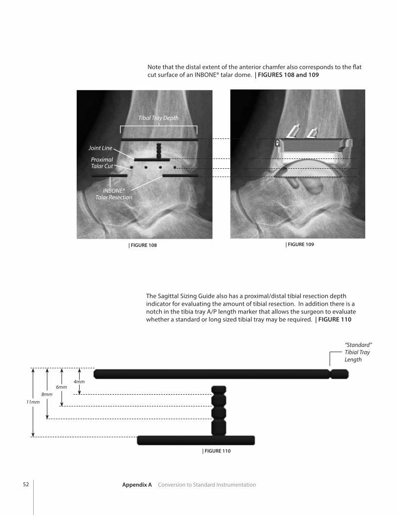
Note that the distal extent of the anterior chamfer also corresponds to the flat cut surface of an INBONE® talar dome. | FIGURES 108 and 109
| FIGURE 108
4mm6mm
8mm11mm
| FIGURE 109
The Sagittal Sizing Guide also has a proximal/distal tibial resection depth indicator for evaluating the amount of tibial resection. In addition there is a notch in the tibia tray A/P length marker that allows the surgeon to evaluate whether a standard or long sized tibial tray may be required. | FIGURE 110
“Standard”Tibial TrayLength
| FIGURE 110
INBONE®Talar Resection
Tibal Tray Depth
ProximalTalar Cut
Joint Line
Appendix A Conversion to Standard Instrumentation52
“Standard”Tibial TrayLength
Drill Tibial Corners
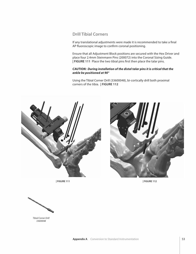
If any translational adjustments were made it is recommended to take a final AP fluoroscopic image to confirm coronal positioning.
Ensure that all Adjustment Block positions are secured with the Hex Driver and place four 2.4mm Steinmann Pins (200072) into the Coronal Sizing Guide. | FIGURE 111 Place the two tibial pins first then place the talar pins.
CAUTION: During installation of the distal talar pins it is critical that the ankle be positioned at 90°
Using the Tibial Corner Drill (33600048), bi-cortically drill both proximal corners of the tibia. | FIGURE 112
| FIGURE 111 | FIGURE 112
Tibial Corner Drill33600048
Appendix A Conversion to Standard Instrumentation 53
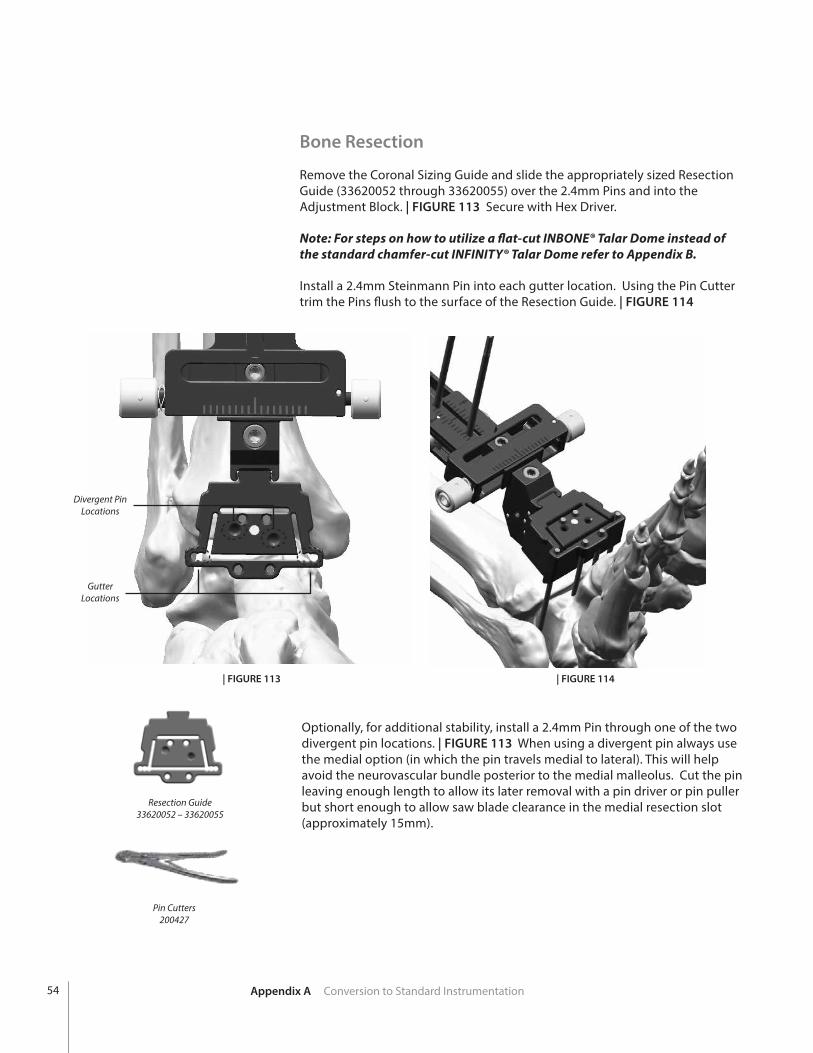
Bone Resection
Remove the Coronal Sizing Guide and slide the appropriately sized Resection Guide (33620052 through 33620055) over the 2.4mm Pins and into the Adjustment Block. | FIGURE 113 Secure with Hex Driver.
Note: For steps on how to utilize a flat-cut INBONE® Talar Dome instead of the standard chamfer-cut INFINITY® Talar Dome refer to Appendix B.
Install a 2.4mm Steinmann Pin into each gutter location. Using the Pin Cutter trim the Pins flush to the surface of the Resection Guide. | FIGURE 114
Resection Guide33620052 – 33620055
Divergent PinLocations
GutterLocations
| FIGURE 114| FIGURE 113
Optionally, for additional stability, install a 2.4mm Pin through one of the two divergent pin locations. | FIGURE 113 When using a divergent pin always use the medial option (in which the pin travels medial to lateral). This will help avoid the neurovascular bundle posterior to the medial malleolus. Cut the pin leaving enough length to allow its later removal with a pin driver or pin puller but short enough to allow saw blade clearance in the medial resection slot (approximately 15mm).
Pin Cutters200427
Appendix A Conversion to Standard Instrumentation54

Using the appropriate size Saw Blade and oscillating bone saw make the tibial and talar bone resections. This includes cutting though the proximal, distal, medial and lateral slots of the Resection Guide.
Remove the divergent Steinmann Pin then remove the Resection Guide and remaining Steinmann Pins. Check that the talar resection is complete by using a 1/2 inch osteotome. Complete the cut if necessary and gently lever the resected bone out anteriorly.
Refer back to page 20 for the remaining steps to complete the procedure.
Appendix A Conversion to Standard Instrumentation 55
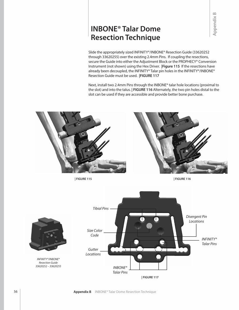
Slide the appropriately sized INFINITY®/INBONE® Resection Guide (33620252 through 33620255) over the existing 2.4mm Pins. If coupling the resections, secure the Guide into either the Adjustment Block or the PROPHECY® Conversion Instrument (not shown) using the Hex Driver. |Figure 115 If the resections have already been decoupled, the INFINITY® Talar pin holes in the INFINITY®/INBONE® Resection Guide must be used. |FIGURE 117
Next, install two 2.4mm Pins through the INBONE® talar hole locations (proximal to the slot) and into the talus. | FIGURE 116 Alternately, the two pin holes distal to the slot can be used if they are accessible and provide better bone purchase.
| FIGURE 116| FIGURE 115
INFINITY®/INBONE® Resection Guide
33620252 – 33620255
Tibial Pins
Size Color Code
Gutter Locations
INBONE® Talar Pins
Divergent Pin Locations
INFINITY® Talar Pins
| FIGURE 117
Appendix B INBONE® Talar Dome Resection Technique56
App
endi
x B
INBONE® Talar Dome Resection Technique
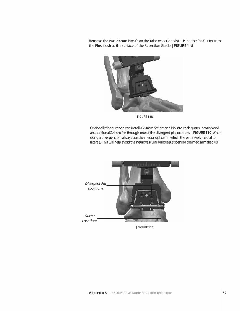
Remove the two 2.4mm Pins from the talar resection slot. Using the Pin Cutter trim the Pins flush to the surface of the Resection Guide. | FIGURE 118
| FIGURE 118
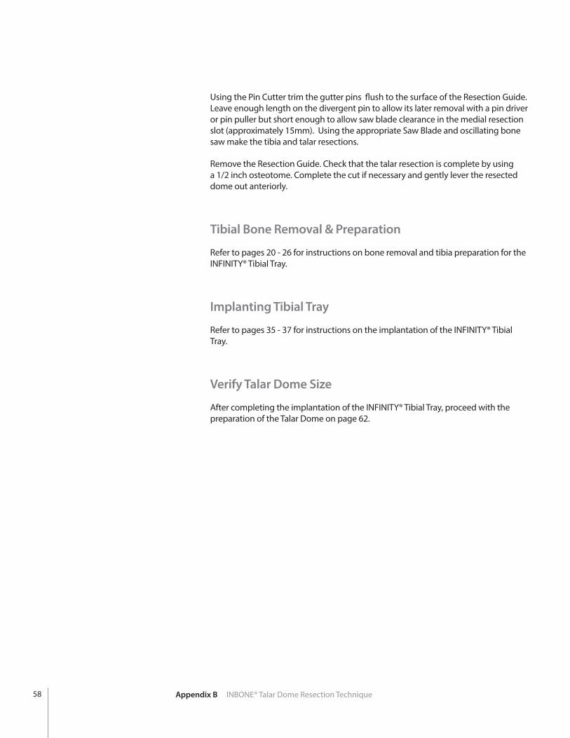
Optionally the surgeon can install a 2.4mm Steinmann Pin into each gutter location and an additional 2.4mm Pin through one of the divergent pin locations. | FIGURE 119 When using a divergent pin always use the medial option (in which the pin travels medial to lateral). This will help avoid the neurovascular bundle just behind the medial malleolus.
| FIGURE 119
Gutter Locations
Divergent Pin Locations
Appendix B INBONE® Talar Dome Resection Technique 57
Using the Pin Cutter trim the gutter pins flush to the surface of the Resection Guide. Leave enough length on the divergent pin to allow its later removal with a pin driver or pin puller but short enough to allow saw blade clearance in the medial resection slot (approximately 15mm). Using the appropriate Saw Blade and oscillating bone saw make the tibia and talar resections.
Remove the Resection Guide. Check that the talar resection is complete by using a 1/2 inch osteotome. Complete the cut if necessary and gently lever the resected dome out anteriorly.
Tibial Bone Removal & Preparation
Refer to pages 20 - 26 for instructions on bone removal and tibia preparation for the INFINITY® Tibial Tray.
Implanting Tibial Tray
Refer to pages 35 - 37 for instructions on the implantation of the INFINITY® Tibial Tray.
Verify Talar Dome Size
After completing the implantation of the INFINITY® Tibial Tray, proceed with the preparation of the Talar Dome on page 62.
Appendix B INBONE® Talar Dome Resection Technique58
App
endi
x C
PROPHECY® INBONE®Talar Dome Technique
During the pre-operative planning stages of the PROPHECY® process, if the surgeon chooses to use an INBONE® Talar Dome instead of an INFINITY® Talar Dome this is possible due to the identical articulation geometry of the two systems. | FIGURE 120 The PROPHECY® Talus Guide will then be designed to set talar resection depth to the level of the INBONE® Talar Dome.
Talar Alignment Guide
Place the foot into plantar flexion for maximum exposure of the talar dome and ensure the area around the neck and dome of the talus where the PROPHECY® guide will surface match is free of all soft tissue. Place the PROPHECY® Talus Alignment Guide (PROPINF or PROPINFE [EU only] ) on the talar surface in the best fit location. | FIGURES 121, 122 and 123
In the case of uneven talar dome cartilage wear, improved talar alignment guide accuracy may be achieved by carefully removing the cartilage with a curette from the surface-match area of the talus prior to placing the talus alignment guide.
If any portion of the tibia bone prevents the talus guide from fitting properly on the talus, either remove more of the tibial resection or increase plantar flexion of the foot (or a combination of both).
| FIGURE 122Anterior View
Anterior Distal
| FIGURE 123Medial-Oblique View
PROPHECY® Talus Alignment GuidePROPINF
PROPINFE (EU only)
Note: Use the provided bone models as an additional tactile and visual confirmation that the talus guide is positioned correctly on the patient’s bone.
| FIGURE 121
| FIGURE 120
Appendix C PROPHECY® INBONE® Talar Dome Technique 59
| FIGURE 126
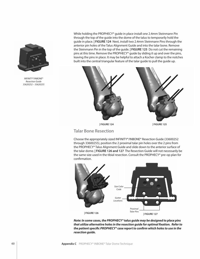
While holding the PROPHECY® guide in place install one 2.4mm Steinmann Pin through the top of the guide into the dome of the talus to temporarily hold the guide in place. | FIGURE 124 Next, install two 2.4mm Steinmann Pins through the anterior pin holes of the Talus Alignment Guide and into the talar bone. Remove the Steinmann Pin in the top of the guide. | FIGURE 125 Do not cut the remaining pins at this time. Remove the PROPHECY® guide by sliding it up and over the pins, leaving the pins in place. It may be helpful to attach a Kocher clamp to the notches built into the central triangular feature of the talar guide to pull the guide up.
Note: In some cases, the PROPHECY® talus guide may be designed to place pins that utilize alternative holes in the resection guide for optimal fixation. Refer to the patient specific PROPHECY® case report to confirm which holes to use in the resection guide.
Talar Bone Resection
Choose the appropriately sized INFINITY®/INBONE® Resection Guide (33600252 through 33600255), position the 2 proximal talar pin holes over the 2 pins from the PROPHECY® Talus Alignment Guide and slide down to the anterior surface of the talar dome. | FIGURE 126 and 127 The Resection Guide will not necessarily be the same size used in the tibial resection. Consult the PROPHECY® pre-op plan for confirmation.
INFINITY®/INBONE® Resection Guide
33620252 – 33620255
Size Color Code
Gutter Locations
Proximal Talar Pins
| FIGURE 127
| FIGURE 124 | FIGURE 125
Appendix C PROPHECY® INBONE® Talar Dome Technique60

The surgeon has the option to fluoroscopically verify the proximal/distal location and flexion/extension angle of the talar component prior to talar resection. Obtain a true lateral view by aligning the c-arm so that both talar Steinmann Pins appear as one.
In addition the surgeon can compare to images in the PROPHECY® Pre-Operative plan to verify accuracy of the talar guide.
Insert two additional 2.4mm Steinmann pins into the medial and lateral gutters for protection of the malleoli. Use the Pin Cutter to cut the Steinmann pins close to the surface of the Resection Guide.
Using the appropriate Saw Blade and oscillating bone saw make the talar resection (distal slot of the Saw Guide).
CAUTION: It may be necessary to manually hold the resection guide in place as excessive vibration from the saw can cause the Saw Guide to work itself off the ends of the cut Steinmann Pins.
Remove the Resection Guide. Check that the talar resection is complete by using a 1/2 inch osteotome. Complete the cut if necessary and gently lever the resected dome out anteriorly.
Tibial Bone Removal & Preparation
Refer to pages 20 - 26 for instructions on bone removal and tibia preparation for the INFINITY® Tibial Tray.
Implanting Tibial Tray
Refer to pages 35 - 37 for instructions on the implantation of the INFINITY® Tibial Tray.
Verify Talar Dome Size
After completing the implantation of the INFINITY® Tibial Tray, proceed with the preparation of the Talar Dome on page 62.
Appendix C PROPHECY® INBONE® Talar Dome Technique 61
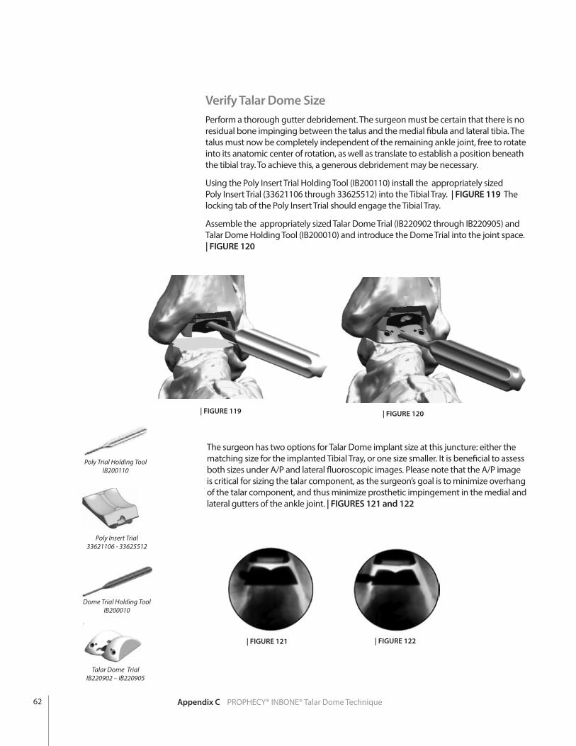
Verify Talar Dome SizePerform a thorough gutter debridement. The surgeon must be certain that there is no residual bone impinging between the talus and the medial fibula and lateral tibia. The talus must now be completely independent of the remaining ankle joint, free to rotate into its anatomic center of rotation, as well as translate to establish a position beneath the tibial tray. To achieve this, a generous debridement may be necessary.
Using the Poly Insert Trial Holding Tool (IB200110) install the appropriately sized Poly Insert Trial (33621106 through 33625512) into the Tibial Tray. | FIGURE 119 The locking tab of the Poly Insert Trial should engage the Tibial Tray.
Assemble the appropriately sized Talar Dome Trial (IB220902 through IB220905) and Talar Dome Holding Tool (IB200010) and introduce the Dome Trial into the joint space. | FIGURE 120
| FIGURE 119 | FIGURE 120
The surgeon has two options for Talar Dome implant size at this juncture: either the matching size for the implanted Tibial Tray, or one size smaller. It is beneficial to assess both sizes under A/P and lateral fluoroscopic images. Please note that the A/P image is critical for sizing the talar component, as the surgeon’s goal is to minimize overhang of the talar component, and thus minimize prosthetic impingement in the medial and lateral gutters of the ankle joint. | FIGURES 121 and 122
| FIGURE 121 | FIGURE 122
Poly Insert Trial33621106 - 33625512
Dome Trial Holding ToolIB200010
Talar Dome Trial IB220902 – IB220905
Poly Trial Holding ToolIB200110
Appendix C PROPHECY® INBONE® Talar Dome Technique62
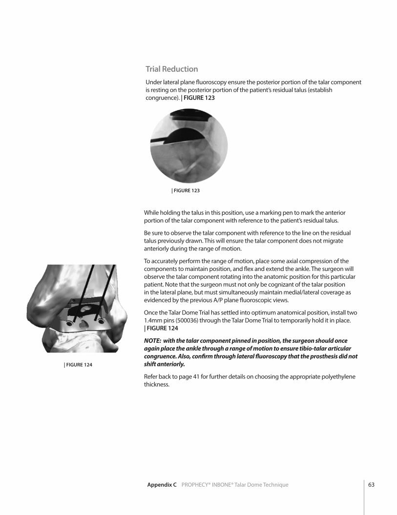
Trial ReductionUnder lateral plane fluoroscopy ensure the posterior portion of the talar component is resting on the posterior portion of the patient’s residual talus (establish congruence). | FIGURE 123
| FIGURE 123
While holding the talus in this position, use a marking pen to mark the anterior portion of the talar component with reference to the patient’s residual talus.
Be sure to observe the talar component with reference to the line on the residual talus previously drawn. This will ensure the talar component does not migrate anteriorly during the range of motion.
To accurately perform the range of motion, place some axial compression of the components to maintain position, and flex and extend the ankle. The surgeon will observe the talar component rotating into the anatomic position for this particular patient. Note that the surgeon must not only be cognizant of the talar position in the lateral plane, but must simultaneously maintain medial/lateral coverage as evidenced by the previous A/P plane fluoroscopic views.
Once the Talar Dome Trial has settled into optimum anatomical position, install two 1.4mm pins (500036) through the Talar Dome Trial to temporarily hold it in place. | FIGURE 124
NOTE: with the talar component pinned in position, the surgeon should once again place the ankle through a range of motion to ensure tibio-talar articular congruence. Also, confirm through lateral fluoroscopy that the prosthesis did not shift anteriorly.
Refer back to page 41 for further details on choosing the appropriate polyethylene thickness.
| FIGURE 124
Appendix C PROPHECY® INBONE® Talar Dome Technique 63
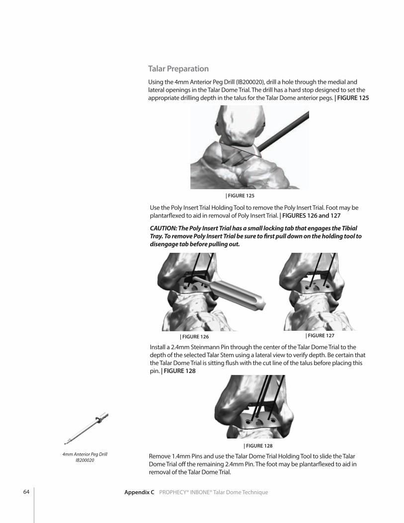
Talar PreparationUsing the 4mm Anterior Peg Drill (IB200020), drill a hole through the medial and lateral openings in the Talar Dome Trial. The drill has a hard stop designed to set the appropriate drilling depth in the talus for the Talar Dome anterior pegs. | FIGURE 125
| FIGURE 125
Use the Poly Insert Trial Holding Tool to remove the Poly Insert Trial. Foot may be plantarflexed to aid in removal of Poly Insert Trial. | FIGURES 126 and 127
CAUTION: The Poly Insert Trial has a small locking tab that engages the Tibial Tray. To remove Poly Insert Trial be sure to first pull down on the holding tool to disengage tab before pulling out.
| FIGURE 126 | FIGURE 127
Install a 2.4mm Steinmann Pin through the center of the Talar Dome Trial to the depth of the selected Talar Stem using a lateral view to verify depth. Be certain that the Talar Dome Trial is sitting flush with the cut line of the talus before placing this pin. | FIGURE 128
| FIGURE 128
Remove 1.4mm Pins and use the Talar Dome Trial Holding Tool to slide the Talar Dome Trial off the remaining 2.4mm Pin. The foot may be plantarflexed to aid in removal of the Talar Dome Trial.
4mm Anterior Peg Drill IB200020
Appendix C PROPHECY® INBONE® Talar Dome Technique64
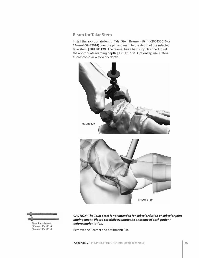
Ream for Talar StemInstall the appropriate length Talar Stem Reamer (10mm-200432010 or 14mm-200432014) over the pin and ream to the depth of the selected talar stem. | FIGURE 129 The reamer has a hard stop designed to set the appropriate reaming depth. | FIGURE 130 Optionally, use a lateral fluoroscopic view to verify depth.
| FIGURE 129
| FIGURE 130
CAUTION: The Talar Stem is not intended for subtalar fusion or subtalar joint impingement. Please carefully evaluate the anatomy of each patient before implantation.
Remove the Reamer and Steinmann Pin.
Talar Stem Reamers(10mm-200432010)(14mm-200432014)
Appendix C PROPHECY® INBONE® Talar Dome Technique 65
Talar Dome ImpactorIB200030
ANTERIOR
POSTERIOR
ANTERIOR
POSTERIOR
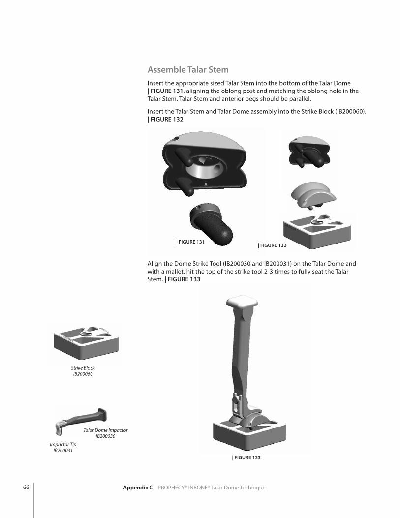
Align the Dome Strike Tool (IB200030 and IB200031) on the Talar Dome and with a mallet, hit the top of the strike tool 2-3 times to fully seat the Talar Stem. | FIGURE 133
| FIGURE 132| FIGURE 131
Strike BlockIB200060
Assemble Talar StemInsert the appropriate sized Talar Stem into the bottom of the Talar Dome | FIGURE 131, aligning the oblong post and matching the oblong hole in the Talar Stem. Talar Stem and anterior pegs should be parallel.
Insert the Talar Stem and Talar Dome assembly into the Strike Block (IB200060). | FIGURE 132
| FIGURE 133
Impactor TipIB200031
Appendix C PROPHECY® INBONE® Talar Dome Technique66
Install Talar DomePlace the foot in plantar flexion and insert the Tibial Tray Protector (33620152 through 33620155) into the Tibial Tray to protect the Talar Dome surface during installation. If choosing to cement, apply bone cement to the bottom surface of the Talar Dome.
CAUTION: In the United States, the ankle prosthesis is intended for cement use only.
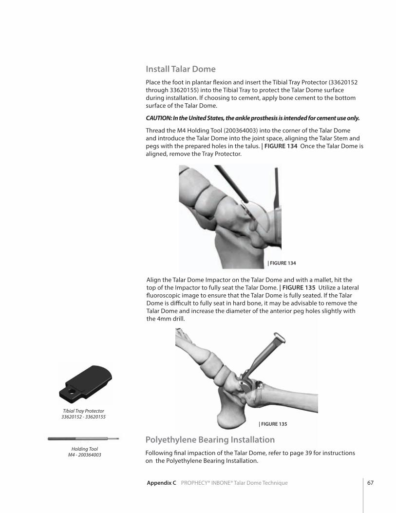
Thread the M4 Holding Tool (200364003) into the corner of the Talar Dome and introduce the Talar Dome into the joint space, aligning the Talar Stem and pegs with the prepared holes in the talus. | FIGURE 134 Once the Talar Dome is aligned, remove the Tray Protector.
Align the Talar Dome Impactor on the Talar Dome and with a mallet, hit the top of the Impactor to fully seat the Talar Dome. | FIGURE 135 Utilize a lateral fluoroscopic image to ensure that the Talar Dome is fully seated. If the Talar Dome is difficult to fully seat in hard bone, it may be advisable to remove the Talar Dome and increase the diameter of the anterior peg holes slightly with the 4mm drill.
| FIGURE 134
| FIGURE 135
Polyethylene Bearing InstallationFollowing final impaction of the Talar Dome, refer to page 39 for instructions on the Polyethylene Bearing Installation.
Tibial Tray Protector33620152 - 33620155
Holding ToolM4 - 200364003
Appendix C PROPHECY® INBONE® Talar Dome Technique 67
App
endi
x D
INFINITY®Instrumentation
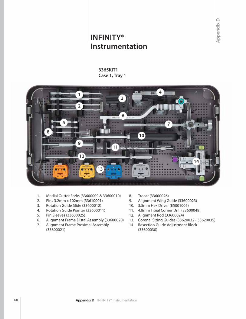
1. Medial Gutter Forks (33600009 & 33600010)2. Pins 3.2mm x 102mm (33610001)3. Rotation Guide Slide (33600012)4. Rotation Guide Pointer (33600011)5. Pin Sleeves (33600025)6. Alignment Frame Distal Assembly (33600020)7. Alignment Frame Proximal Assembly
(33600021)
8. Trocar (33600026)9. Alignment Wing Guide (33600023)10. 3.5mm Hex Driver (E5001005)11. 4.8mm Tibial Corner Drill (33600048)12. Alignment Rod (33600024)13. Coronal Sizing Guides (33620032 - 33620035)14. Resection Guide Adjustment Block
(33600030)
Appendix D INFINITY® Instrumentation
3365KIT1Case 1, Tray 1
1
2
56
7
8
9
10
11
12
13
14
34
68
Appendix D INFINITY® Instrumentation
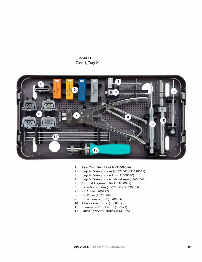
1. Talar 2mm Recut Guide (33609056)2. Sagittal Sizing Guides (33620042 - 33620045)3. Sagittal Sizing Guide Arm (33600040)4. Sagittal Sizing Guide Ratchet Arm (33600068)5. Coronal Alignment Rod (33600027)6. Resection Guides (33620052 - 33620055)7. Pin Cutter (200427)8. Pin Puller (18770140)9. Bone Release Tool (IB200050)10. Tibia Corner Chisel (33600058)11. Steinmann Pins 2.4mm (200072)12. Quick Connect Handle (44180025)
3365KIT1Case 1, Tray 2
12
3
4 5
6 7 8
910
11
12
69

Appendix D INFINITY® Instrumentation
3365KIT1Case 2, Tray 1
1. Poly Insert Trials (33621106 - 33625512)2. Talar Dome Trials (33600071 - 33600075)3. Tibial Tray Trials (33620062 - 33620065)4. Posterior Tibial Peg Broach (33600069)5. Anterior Tibial Peg Broach (33600067)6. Poly Trial Handle (IB200110)7. Self Retaining Laminar Spreader (33609012)8. PROPHECY® Conversion Guide (33600200)
1
4
5
6
7
2
3
8
70

Appendix D INFINITY® Instrumentation
1. Talar Resection Guide Bases (33600091 - 33600095)2. Talar Chamfer Pilot Guides (33600101 - 33600105)3. Talar Chamfer Finish Guides (33600111 - 33600115)4. Talar Reamers (33600123 & 33600126)5. T-Handle Pin Driver (33600120)6. Threaded Talar Pins (3361002 & 33610003)7. Talar Peg Drill Guides (33600161 - 33600165)8. Talar Peg Drill, 4mm (IB200020)9. Tibial Tray Insertion Handle (33600130)10. Tibial Tray Impaction Inserts (33600132 - 33620135)
1
2
3
5
6
89
4
7
10
3365KIT1Case 2, Tray 2
71
Appendix D INFINITY® Instrumentation
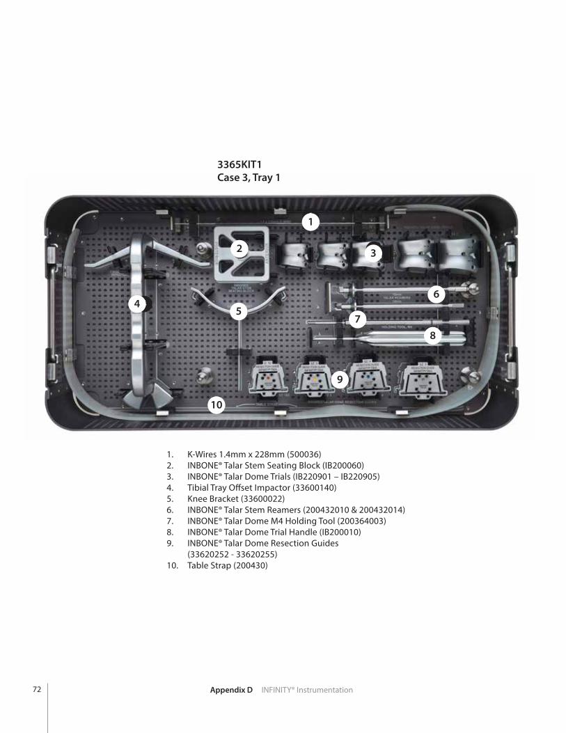
1. K-Wires 1.4mm x 228mm (500036)2. INBONE® Talar Stem Seating Block (IB200060)3. INBONE® Talar Dome Trials (IB220901 – IB220905)4. Tibial Tray Offset Impactor (33600140)5. Knee Bracket (33600022)6. INBONE® Talar Stem Reamers (200432010 & 200432014)7. INBONE® Talar Dome M4 Holding Tool (200364003)8. INBONE® Talar Dome Trial Handle (IB200010)9. INBONE® Talar Dome Resection Guides
(33620252 - 33620255)10. Table Strap (200430)
4
2
1
3
6
7
8
9
10
6
1
2
45
6
78
9
10
3
3365KIT1Case 3, Tray 1
72
1. K-Wires 1.4mm x 228mm (500036)2. INBONE® Talar Stem Seating Block (IB200060)3. INBONE® Talar Dome Trials (IB220901 – IB220905)4. Tibial Tray Offset Impactor (33600140)5. Knee Bracket (33600022)6. INBONE® Talar Stem Reamers (200432010 & 200432014)7. INBONE® Talar Dome M4 Holding Tool (200364003)8. INBONE® Talar Dome Trial Handle (IB200010)9. INBONE® Talar Dome Resection Guides
(33620252 - 33620255)10. Table Strap (200430)
TIBIAL TRAY IMPACTOR STRAIGHT
DOME STRIKE HANDLE
POLY INSERTER RAIL ASSEMBLY
DOME STRIKE
TIP
TIBIAL TRAY PROTECTORS
SZ 1&2 SZ 3 SZ 4 SZ 5
POLY INSERTER GUIDE RAILS
SZ 1&2 SZ 3 SZ 4 SZ 5
33600530
ATTACHMENT SCREWS & NUTS
Appendix D INFINITY® Instrumentation
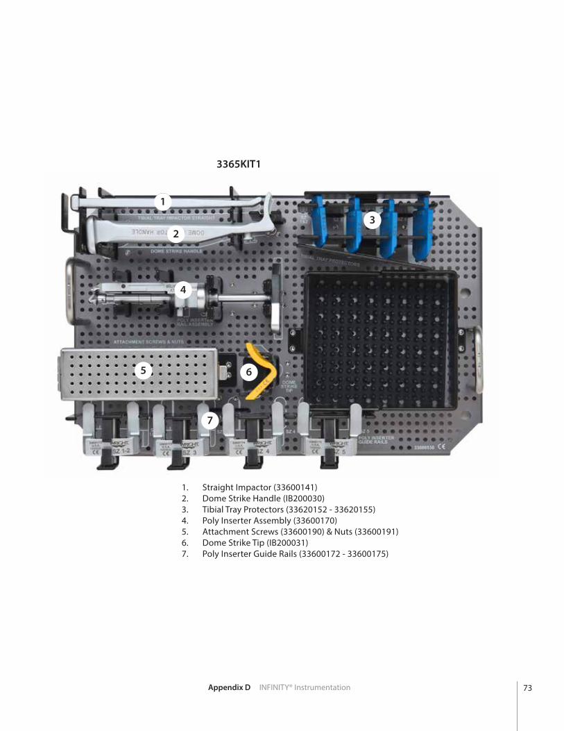
3365KIT1Case 3, Tray 2
1. Straight Impactor (33600141)2. Dome Strike Handle (IB200030)3. Tibial Tray Protectors (33620152 - 33620155)4. Poly Inserter Assembly (33600170)5. Attachment Screws (33600190) & Nuts (33600191)6. Dome Strike Tip (IB200031)7. Poly Inserter Guide Rails (33600172 - 33600175)
1
2
4
5 6
7
3
11
2
4
5 6
7
3
73

Appendix D INFINITY® Instrumentation
3365KIT1 - INFINITY® Instrument Kit
Part # Description
33600009 MEDIAL GUTTER FORK, SMALL
33600010 MEDIAL GUTTER FORK, LARGE
33600011 ROTATION GUIDE POINTER
33600012 ROTATION GUIDE SLIDE
33600020 ALIGNMENT FRAME DIST SUB ASSY
33600021 ALIGNMENT FRAME PROX SUB ASSY
33600022 KNEE BRACKET
33600023 ALIGNMENT WING GUIDE
33600024 ALIGNMENT ROD
33600025 PIN SLEEVE
33600026 TROCAR
33600030 RESECTION ADJUSTMENT BLOCK
33620032 CORONAL SIZING GUIDE, SZ 1-2
33620033 CORONAL SIZING GUIDE, SZ 3
33620034 CORONAL SIZING GUIDE, SZ 4
33620035 CORONAL SIZING GUIDE, SZ 5
33620040 SAGITTAL SIZING GUIDE ARM
33620042 SAGITTAL SIZING GUIDE, SZ1-2
33620043 SAGITTAL SIZING GUIDE, SZ3
33620044 SAGITTAL SIZING GUIDE, SZ4
33620045 SAGITTAL SIZING GUIDE, SZ5
33600048 TIBIAL CORNER DRILL, 4.8MM
33620052 RESECTION GUIDE, SZ 1-2
33620053 RESECTION GUIDE, SZ 3
33620054 RESECTION GUIDE, SZ 4
33620055 RESECTION GUIDE, SZ 5
33600058 TIBIAL CORNER CHISEL
Part # Description
33620062 TRIAL TIBIAL TRAY, SZ1-2
33620063 TRIAL TIBIAL TRAY, SZ3
33620064 TRIAL TIBIAL TRAY, SZ4
33620065 TRIAL TIBIAL TRAY, SZ5
33600069 TIBIAL PEG DRILL, 3.7MM
33600071 TRIAL TALAR DOME, SZ1
33600072 TRIAL TALAR DOME, SZ2
33600073 TRIAL TALAR DOME, SZ3
33600074 TRIAL TALAR DOME, SZ4
33600075 TRIAL TALAR DOME, SZ5
33600091 TALAR RESECT GUIDE BASE, SZ1
33600092 TALAR RESECT GUIDE BASE, SZ2
33600093 TALAR RESECT GUIDE BASE, SZ3
33600094 TALAR RESECT GUIDE BASE, SZ4
33600095 TALAR RESECT GUIDE BASE, SZ5
33600101 ANTER TALAR PILOT GUIDE, SZ1
33600102 ANTER TALAR PILOT GUIDE, SZ2
33600103 ANTER TALAR PILOT GUIDE, SZ3
33600104 ANTER TALAR PILOT GUIDE, SZ4
33600105 ANTER TALAR PILOT GUIDE, SZ5
33600111 ANTER TALAR FINISH GUIDE, SZ1
33600112 ANTER TALAR FINISH GUIDE, SZ2
33600113 ANTER TALAR FINISH GUIDE, SZ3
33600114 ANTER TALAR FINISH GUIDE, SZ4
33600115 ANTER TALAR FINISH GUIDE, SZ5
33600120 T-HANDLE PIN DRIVER
33600123 TALAR REAMER, SZ 1-3
33600126 TALAR REAMER, SZ 4-6
74
Appendix D INFINITY® Instrumentation
3365KIT1 - INFINITY® Instrument Kit
Part # Description
33600130 TIBIAL TRAY INSERT HANDLE
3360132 TIB TRAY IMPACT INSERT, SZ1-2
33600133 TIB TRAY IMPACT INSERT, SZ3
33600134 TIB TRAY IMPACT INSERT, SZ4
33600135 TIB TRAY IMPACT INSERT, SZ5
33600140 TIBIAL TRAY IMPACTOR, OFFSET
33600141 TIBIAL TRAY IMPACTOR, STRAIGHT
33620152 TIBIAL TRAY PROTECTOR, SZ1-2
33620153 TIBIAL TRAY PROTECTOR, SZ3
33620154 TIBIAL TRAY PROTECTOR, SZ4
33620155 TIBIAL TRAY PROTECTOR, SZ5
33600161 TALAR PEG DRILL GUIDE, SZ1
33600162 TALAR PEG DRILL GUIDE, SZ2
33600163 TALAR PEG DRILL GUIDE, SZ3
33600164 TALAR PEG DRILL GUIDE, SZ4
33600165 TALAR PEG DRILL GUIDE, SZ5
33600170 POLY INSERTER RAIL ASSY
33600172 POLY INSERT GUIDE RAIL, SZ1-2
33600173 POLY INSERT GUIDE RAIL, SZ3
33600174 POLY INSERT GUIDE RAIL, SZ4
33600175 POLY INSERT GUIDE RAIL, SZ5
33600190 POLY INSERT ATTACHMENT SCREW
33600191 POLY INSERT ATTACHMENT NUT
33620252 RESECTION GUIDE INBONE® TALUS, SZ1-2
33620253 RESECTION GUIDE INBONE® TALUS, SZ3
33620254 RESECTION GUIDE INBONE® TALUS, SZ4
33620255 RESECTION GUIDE INBONE® TALUS, SZ5
Part # Description
33621106 TRIAL POLY INSERT, SZ1/1+ 6MM
33621108 TRIAL POLY INSERT, SZ1/1+ 8MM
33621110 TRIAL POLY INSERT, SZ1/1+ 10MM
33621112 TRIAL POLY INSERT, SZ1/1+ 12MM
33622206 TRIAL POLY INSERT, SZ2 6MM
33622208 TRIAL POLY INSERT, SZ2 8MM
33602210 TRIAL POLY INSERT, SZ2 10MM
33602212 TRIAL POLY INSERT, SZ2 12MM
33623206 TRIAL POLY INSERT, SZ2+ 6MM
33623208 TRIAL POLY INSERT, SZ2+ 8MM
33603210 TRIAL POLY INSERT, SZ2+ 10MM
33603212 TRIAL POLY INSERT, SZ2+ 12MM
33623306 TRIAL POLY INSERT, SZ3 6MM
33623308 TRIAL POLY INSERT, SZ3 8MM
33603310 TRIAL POLY INSERT, SZ3 10MM
33603312 TRIAL POLY INSERT, SZ3 12MM
33624307 TRIAL POLY INSERT, SZ3+ 7MM
33624309 TRIAL POLY INSERT, SZ3+ 9MM
33604311 TRIAL POLY INSERT, SZ3+ 11MM
33604313 TRIAL POLY INSERT, SZ3+ 13MM
33624406 TRIAL POLY INSERT, SZ4 6MM
33624408 TRIAL POLY INSERT, SZ4 8MM
33604410 TRIAL POLY INSERT, SZ4 10MM
33604412 TRIAL POLY INSERT, SZ4 12MM
33625407 TRIAL POLY INSERT, SZ4+ 7MM
33625409 TRIAL POLY INSERT, SZ4+ 9MM
33605411 TRIAL POLY INSERT, SZ4+ 11MM
33605413 TRIAL POLY INSERT, SZ4+ 13MM
33625506 TRIAL POLY INSERT, SZ5 6MM
33625508 TRIAL POLY INSERT, SZ5 8MM
33605510 TRIAL POLY INSERT, SZ5 10MM
33605512 TRIAL POLY INSERT, SZ5 12MM
75

Appendix D INFINITY® Instrumentation
Part # Description
33609012 SELF RETAINING LAMINAR SPREADERS
33610001 PIN 3.2MM X 102MM
33610002 TEMP FIX PIN, TALAR GUIDE LONG
33610003 TEMP FIX PIN, TALAR GUIDE SHORT
E5001005 EVOLUTION® 3.5MM HEX DRIVER
200430 INBONE® TABLE STRAP
200072 INBONE® STEINMANN PIN, 2.4MM
IB200050 INBONE® BONE RELEASE TOOL
IB200110 INBONE® HANDLE TRIAL IMPLANTS
IB200020 INBONE® DRILL TALAR PEG, 4MM
IB200030 INBONE® HANDLE DOME STRIKER
IB200031 INBONE® DOME STRIKE TIP SULCUS
500036 1.4MM K-WIRE
18770140 ORTHOLOC® PIN PULLER
200427 INBONE® PIN CUTTER 3.2
44180025 7.0 MUC HANDLE QUICK CONNECT
IB220901 INBONE® TRIAL TAL DOME #1 SULC
IB220902 INBONE® TRIAL TAL DOME #2 SULC
IB220903 INBONE® TRIAL TAL DOME #3 SULC
IB220904 INBONE® TRIAL TAL DOME #4 SULC
IB220905 INBONE® TRIAL TAL DOME #5 SULC
200432010 INBONE® TALAR REAMER, 10 MM
200432014 INBONE® TALAR REAMER, 14 MM
IB200060 INBONE® SEAT BLOCK TALAR STEM
IB200010 INBONE® TALAR DOME TRIAL HANDLE
200364003 INBONE® HOLDING, TOOL, M4
33600200 PROPHECY® CONVERSION INSTRUMENT
3365KIT1 - INFINITY® Instrument Kit
76
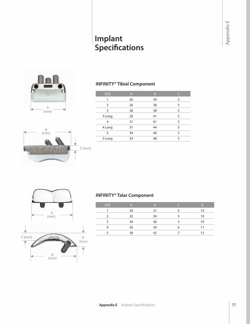
Appendix E Implant Specifications
INFINITY® Tibial Component
INFINITY® Talar Component
Q)
A(mm)
B(mm)
C (mm)
A(mm)
B(mm)
C (mm) D(mm)
ImplantSpecifications
SIZE A B C
1 26 34 5
2 26 38 5
3 28 38 5
3 Long 28 41 5
4 31 41 5
4 Long 31 44 5
5 34 44 5
5 Long 34 48 5
SIZE A B C D
1 30 31 5 10
2 32 34 5 10
3 34 36 5 10
4 36 39 6 11
5 38 42 7 12A
ppen
dix
E
77
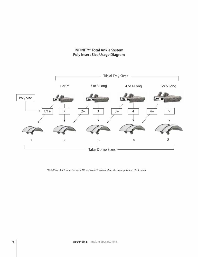
Appendix E Implant Specifications78
INFINITY® Total Ankle System Poly Insert Size Usage Diagram
Tibial Tray Sizes
1 or 2* 3 or 3 Long 4 or 4 Long 5 or 5 Long
Poly Size
1/1+ 2 2+ 3 3+ 4 4+ 5
1 2 3 4 5
Talar Dome Sizes
*Tibial Sizes 1 & 2 share the same ML width and therefore share the same poly insert lock detail.
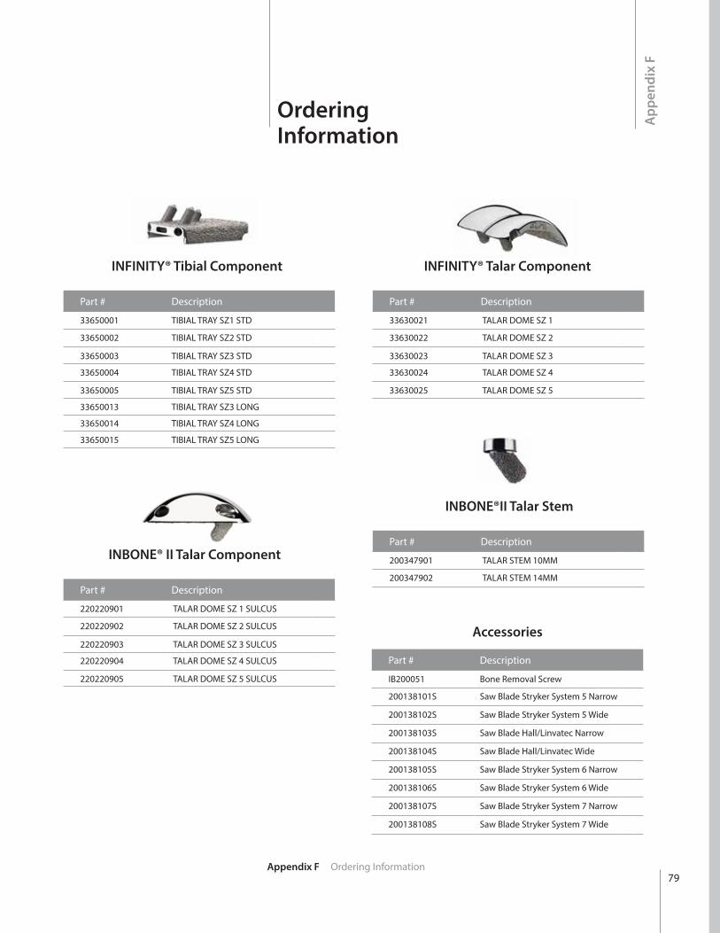
App
endi
x F
OrderingInformation
INFINITY® Tibial Component
INBONE® II Talar Component
INFINITY® Talar Component
INBONE®II Talar Stem
Part # Description
33650001 TIBIAL TRAY SZ1 STD
33650002 TIBIAL TRAY SZ2 STD
33650003 TIBIAL TRAY SZ3 STD
33650004 TIBIAL TRAY SZ4 STD
33650005 TIBIAL TRAY SZ5 STD
33650013 TIBIAL TRAY SZ3 LONG
33650014 TIBIAL TRAY SZ4 LONG
33650015 TIBIAL TRAY SZ5 LONG
Part # Description
220220901 TALAR DOME SZ 1 SULCUS
220220902 TALAR DOME SZ 2 SULCUS
220220903 TALAR DOME SZ 3 SULCUS
220220904 TALAR DOME SZ 4 SULCUS
220220905 TALAR DOME SZ 5 SULCUS
Part # Description
33630021 TALAR DOME SZ 1
33630022 TALAR DOME SZ 2
33630023 TALAR DOME SZ 3
33630024 TALAR DOME SZ 4
33630025 TALAR DOME SZ 5
Part # Description
200347901 TALAR STEM 10MM
200347902 TALAR STEM 14MM
79Appendix F Ordering Information
Accessories
Part # Description
IB200051 Bone Removal Screw
200138101S Saw Blade Stryker System 5 Narrow
200138102S Saw Blade Stryker System 5 Wide
200138103S Saw Blade Hall/Linvatec Narrow
200138104S Saw Blade Hall/Linvatec Wide
200138105S Saw Blade Stryker System 6 Narrow
200138106S Saw Blade Stryker System 6 Wide
200138107S Saw Blade Stryker System 7 Narrow
200138108S Saw Blade Stryker System 7 Wide
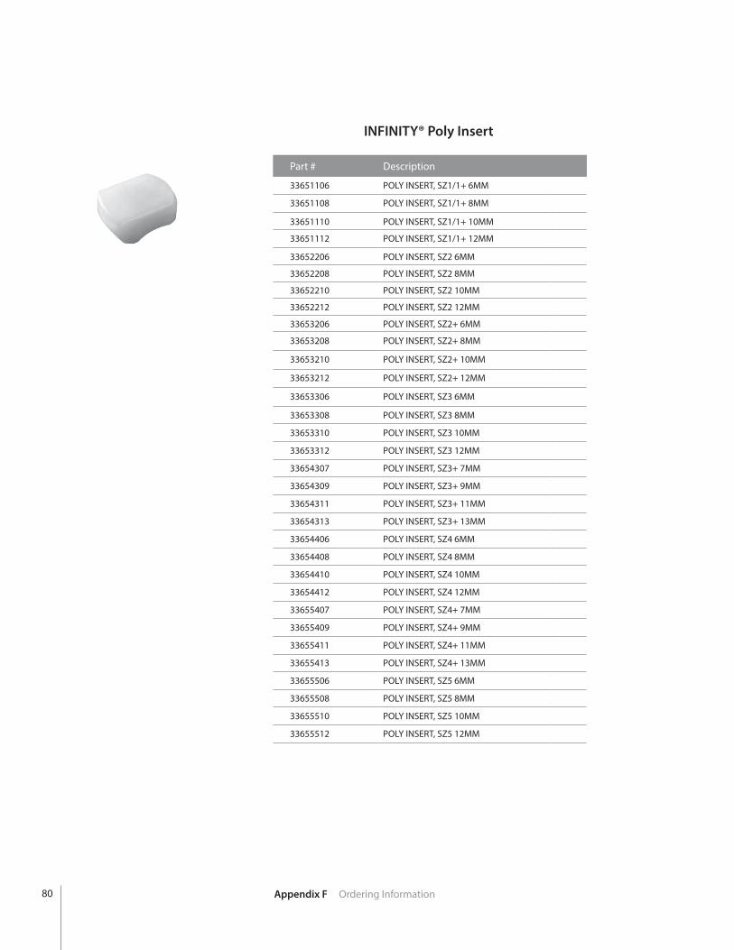
Appendix F Ordering Information
INFINITY® Poly Insert
Part # Description
33651106 POLY INSERT, SZ1/1+ 6MM
33651108 POLY INSERT, SZ1/1+ 8MM
33651110 POLY INSERT, SZ1/1+ 10MM
33651112 POLY INSERT, SZ1/1+ 12MM
33652206 POLY INSERT, SZ2 6MM
33652208 POLY INSERT, SZ2 8MM
33652210 POLY INSERT, SZ2 10MM
33652212 POLY INSERT, SZ2 12MM
33653206 POLY INSERT, SZ2+ 6MM
33653208 POLY INSERT, SZ2+ 8MM
33653210 POLY INSERT, SZ2+ 10MM
33653212 POLY INSERT, SZ2+ 12MM
33653306 POLY INSERT, SZ3 6MM
33653308 POLY INSERT, SZ3 8MM
33653310 POLY INSERT, SZ3 10MM
33653312 POLY INSERT, SZ3 12MM
33654307 POLY INSERT, SZ3+ 7MM
33654309 POLY INSERT, SZ3+ 9MM
33654311 POLY INSERT, SZ3+ 11MM
33654313 POLY INSERT, SZ3+ 13MM
33654406 POLY INSERT, SZ4 6MM
33654408 POLY INSERT, SZ4 8MM
33654410 POLY INSERT, SZ4 10MM
33654412 POLY INSERT, SZ4 12MM
33655407 POLY INSERT, SZ4+ 7MM
33655409 POLY INSERT, SZ4+ 9MM
33655411 POLY INSERT, SZ4+ 11MM
33655413 POLY INSERT, SZ4+ 13MM
33655506 POLY INSERT, SZ5 6MM
33655508 POLY INSERT, SZ5 8MM
33655510 POLY INSERT, SZ5 10MM
33655512 POLY INSERT, SZ5 12MM
80


™ and ® denote Trademarks and Registered Trademarks of Wright Medical Group N.V. or its affiliates.©2016 Wright Medical Group N.V. or its affiliates. All Rights Reserved.
011940B 18-Aug-2015
1023 Cherry Road Memphis, TN 38117 800 238 7117 901 867 9971 www.wright.com
62 Quai Charles de Gaulle 69006 Lyon France+33 (0)4 72 84 10 30 www.tornier.com
18 Amor WayLetchworth Garden CityHertfordshire SG6 1UGUnited Kingdom+44 (0)845 833 4435