promri system - biotronik.cdn.mediamid.com · correct and safe use of the promri® system...
TRANSCRIPT

Cardiac Rhythm Management // Advanced Features // ProMRI® System
ProMRI® SystemTechnical Manual
CAUTIONFederal (U.S.A.) law restricts this device to sale by, or on the order of,
a physician (or properly licensed practitioner).
© 2016 BIOTRONIK, Inc., all rights reserved.

PAGE III
Table of Contents ProMRI® System Technical Manual
Contents1. Basic Information .................................................................................................................1
1.1 About this Manual .............................................................................................................11.1.1 Subject of this manual ..................................................................................................11.1.2 What this manual doesn’t include.................................................................................1
1.2 Target Group .....................................................................................................................11.2.1 Cooperation between professionals from two areas of expertise ................................11.2.2 Knowledge required by the cardiology specialist .........................................................11.2.3 Knowledge required by the radiology specialist ...........................................................1
1.3 Active Device and Lead ...................................................................................................21.3.1 Patient selection, MRI indication ..................................................................................21.3.2 Intended use.................................................................................................................21.3.3 Residual risk ................................................................................................................2
1.4 ProMRI® System ...............................................................................................................22. Safety Warnings ....................................................................................................................9
2.1 Magnetic Resonance Imaging - Possible Interactions .....................................................92.1.1 Problematic interactions ..............................................................................................92.1.2 Fields in the MRI scanner.............................................................................................92.1.3 Force of the static and gradient magnetic fields ...........................................................92.1.4 Interactions resulting from induced AC voltages ..........................................................92.1.5 Thermal interactions ..................................................................................................102.1.6 Image interference and artifacts .................................................................................10
2.2 Warnings ........................................................................................................................102.2.1 Preliminary notes .......................................................................................................102.2.2 Warnings ....................................................................................................................10
3. MRI Conditions for Use ......................................................................................................113.1 Patient Pre-MRI Conditions ............................................................................................113.2 MRI Scanner Limitations ................................................................................................113.3 Restrictions during the MR Scan ....................................................................................11
4. MRI Examination .................................................................................................................134.1 Preliminary Examination .................................................................................................13
4.1.1 Cooperation between specialists................................................................................134.1.2 Checking the suitability of the patient and the implanted system ...............................134.1.3 Performing an MR scan and programming the MRI Mode .........................................13
4.2 MRI Examination ............................................................................................................154.2.1 Prerequisites ..............................................................................................................154.2.2 Basic conditions and restrictions ................................................................................154.2.3 Patient monitoring during the MR scan ......................................................................154.2.4 Completion of the examination ...................................................................................15
PAGE I
PAGE IV
Table of ContentsProMRI® System Technical Manual
5. Post MR Scan Requirements .............................................................................................175.1 Follow-Up Procedure ......................................................................................................17
6. Clinical Study ......................................................................................................................196.1 ProMRI Phase B Clinical Study ......................................................................................19
6.1.1 Primary Objectives .....................................................................................................196.1.2 Methods......................................................................................................................196.1.3 Results .......................................................................................................................19
6.2 ProMRI Phase C Clinical Study ......................................................................................296.2.1 Primary Objectives .....................................................................................................296.2.2 Methods......................................................................................................................296.2.3 Results .......................................................................................................................29
7. Adverse Events ...................................................................................................................377.1 Observed Adverse Events ..............................................................................................37
7.1.1 ProMRI Phase B.........................................................................................................377.1.2 ProMRI Phase C ........................................................................................................38
PAGE II
Basic InformationProMRI® System Technical Manual
PAGE 1
1. Basic Information
1.1 About this Manual
1.1.1 Subject of this manualThis manual provides information about the safe application of an MR scan on patients with a ProMRI® system, which consists of a ProMRI® device and the leads listed in Section 1.4.
This manual will focus on the MRI conditions and safety measures that are to be adhered to before and during an MR scan using the ProMRI® system.
1.1.2 What this manual doesn’t includeCorrect and safe use of the ProMRI® system components is described in the technical manuals provided with the products and is not a subject of this manual.
Correct and safe use of an MRI scanner is not described in this manual unless directly related to the ProMRI® System.
1.2 Target Group
1.2.1 Cooperation between professionals from two areas of expertiseThis manual is intended for physicians and medical staff who have the knowledge and experience required to prepare and perform MR scans on patients with a pacemaker, ICD, or CRT-D.
Preparation and application of an MR scan on a CRM patient requires close cooperation between a cardiology professional, as a specialist for the device system, and a radiology professional, as a specialist for the MR scan.
The following sections describe the tasks that each of these specialists is responsible for.
1.2.2 Knowledge required by the cardiology specialistA cardiology professional is required to select and/or approve the patient for the MR scan. Additionally, they must test the device system before the exam, program the device to the MRI mode, ensure its functionality after the exam, and program it back to the mode that was active before the MR scan.
The cardiology professional should be knowledgeable in the following areas and subjects:
• Performing pacemaker/ICD/CRT-D therapy• Handling the BIOTRONIK programmer and especially the following activities:
- Interrogating the active device - Performing follow-up - Updating parameters, including programming the device to the MRI Mode
• All associated risks, possible side effects, and the appropriate safety and therapy measures
1.2.3 Knowledge required by the radiology specialistThe radiology professional is responsible for the successful performance of the MR scan for the purposes of the desired diagnosis. Additionally, the radiology professional is also responsible for ensuring that the restrictive conditions, for which the MRI is to be performed, are observed both before and during the MR scan.
Chapter 1
Basic InformationProMRI® System Technical Manual
PAGE 2
The radiology professional should be knowledgeable in the following areas and subjects:
• Handling MRI scanners• Preparation, performance and analysis of MR scans
1.3 Active Device and Lead The respective intended use of the ProMRI pacemakers, ICDs, CRT-Ds, and lead(s) applies to use of the device system.
NOTE:The technical manuals for the components of the ProMRI system are to be observed.
1.3.1 Patient selection, MRI indicationBefore a patient with an MR conditional device system is selected for an MR scan, the following issues must be resolved:
• There must be a clear indication for the MR scan.• Risk/benefit analysis• All of the exclusion criteria listed in this technical manual have been taken into consideration.• The described restrictions and conditions for the MR scan are to be observed at all times.
1.3.2 Intended useIf particular MRI conditions are fulfilled, MR scans can now be conducted on patients with a combination of a BIOTRONIK active device and lead that has been tested for this purpose.
1.3.3 Residual risk The expected risks and hazards are minimized by the measures performed in this manual. Nevertheless, a residual risk remains.
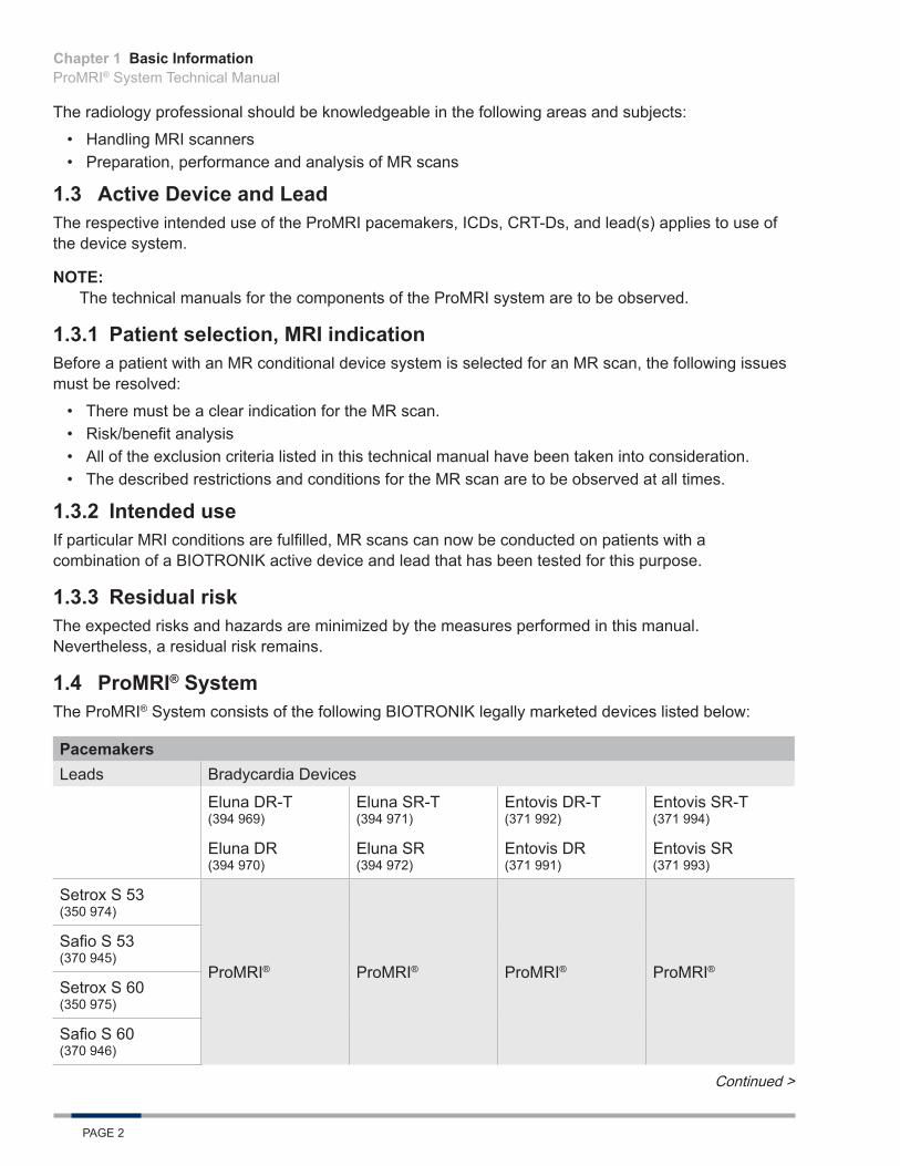
1.4 ProMRI® SystemThe ProMRI® System consists of the following BIOTRONIK legally marketed devices listed below:
PacemakersLeads Bradycardia Devices
Eluna DR-T (394 969)
Eluna SR-T (394 971)
Entovis DR-T (371 992)
Entovis SR-T (371 994)
Eluna DR (394 970)
Eluna SR (394 972)
Entovis DR (371 991)
Entovis SR (371 993)
Setrox S 53 (350 974)
ProMRI® ProMRI® ProMRI® ProMRI®
Safio S 53 (370 945)
Setrox S 60 (350 975)
Safio S 60 (370 946)
Continued >
Chapter 1

Basic InformationProMRI® System Technical Manual
PAGE 3
PacemakersLeads Bradycardia Devices
Eluna DR-T (394 969)
Eluna SR-T (394 971)
Entovis DR-T (371 992)
Entovis SR-T (371 994)
Eluna DR (394 970)
Eluna SR (394 972)
Entovis DR (371 991)
Entovis SR (371 993)
Siello S 45 (362 700)
ProMRI® ProMRI® ProMRI® ProMRI®
Siello S 53 (362 701)
Siello S 60 (362 702)
Solia S 45 (377 176)
Solia S 53 (377 177)
Solia S 60 (377 179)
DX ICDsLeads Tachycardia Devices
Iperia 7 VR-T DX (DF-1) (393 032)
Inventra 7 VR-T DX (DF-1) (399 436)
Iforia 7 VR-T DX (DF-1) (390 090, 390 092, 390 093, 390 095)
Linoxsmart S DX 65/15 (365 500)
ProMRI® ProMRI® ProMRI®
Linoxsmart S DX 65/17 (365 501)
Chapter 1
Basic InformationProMRI® System Technical Manual
PAGE 4
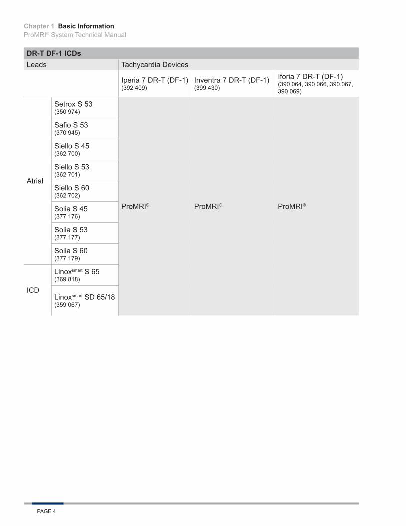
DR-T DF-1 ICDsLeads Tachycardia Devices
Iperia 7 DR-T (DF-1) (392 409)
Inventra 7 DR-T (DF-1) (399 430)
Iforia 7 DR-T (DF-1) (390 064, 390 066, 390 067, 390 069)
Atrial
Setrox S 53 (350 974)
ProMRI® ProMRI® ProMRI®
Safio S 53 (370 945)
Siello S 45 (362 700)
Siello S 53 (362 701)
Siello S 60 (362 702)
Solia S 45 (377 176)
Solia S 53 (377 177)
Solia S 60 (377 179)
ICD
Linoxsmart S 65 (369 818)
Linoxsmart SD 65/18 (359 067)
Chapter 1
Basic InformationProMRI® System Technical Manual
PAGE 5
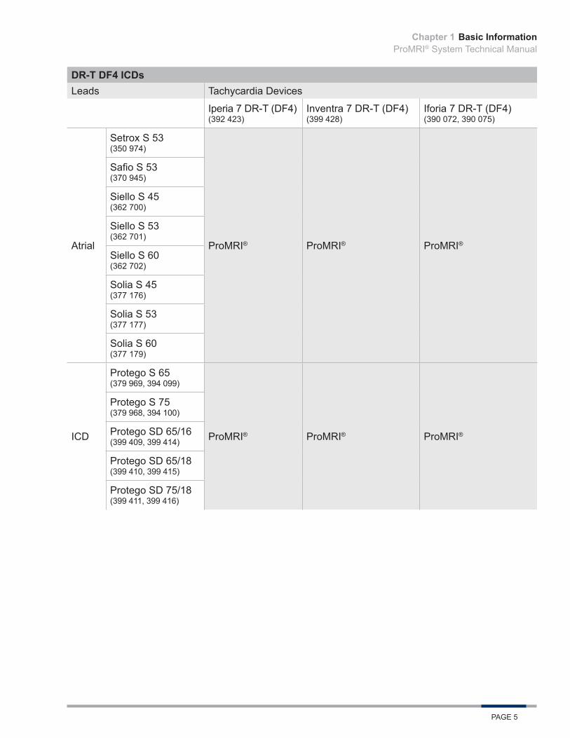
DR-T DF4 ICDsLeads Tachycardia Devices
Iperia 7 DR-T (DF4) (392 423)
Inventra 7 DR-T (DF4) (399 428)
Iforia 7 DR-T (DF4) (390 072, 390 075)
Atrial
Setrox S 53 (350 974)
ProMRI® ProMRI® ProMRI®
Safio S 53 (370 945)
Siello S 45 (362 700)
Siello S 53 (362 701)
Siello S 60 (362 702)
Solia S 45 (377 176)
Solia S 53 (377 177)
Solia S 60 (377 179)
ICD
Protego S 65 (379 969, 394 099)
ProMRI® ProMRI® ProMRI®
Protego S 75 (379 968, 394 100)
Protego SD 65/16 (399 409, 399 414)
Protego SD 65/18 (399 410, 399 415)
Protego SD 75/18 (399 411, 399 416)
Chapter 1
Basic InformationProMRI® System Technical Manual
PAGE 6
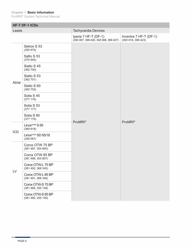
HF-T DF-1 ICDsLeads Tachycardia Devices
Iperia 7 HF-T (DF-1) (393 007, 399 426, 393 008, 399 427)
Inventra 7 HF-T (DF-1) (393 019, 399 423)
Atrial
Setrox S 53 (350 974)
ProMRI® ProMRI®
Safio S 53 (370 945)
Siello S 45 (362 700)
Siello S 53 (362 701)
Siello S 60 (362 702)
Solia S 45 (377 176)
Solia S 53 (377 177)
Solia S 60 (377 179)
ICD
Linoxsmart S 65 (369 818)
Linoxsmart SD 65/18 (359 067)
LV
Corox OTW 75 BP (381 487, 354 805)
Corox OTW 85 BP (381 488, 354 807)
Corox OTW-L 75 BP (381 492, 368 345)
Corox OTW-L 85 BP (381 491, 368 346)
Corox OTW-S 75 BP (381 489, 355 148)
Corox OTW-S 85 BP (381 490, 355 149)
Chapter 1

Basic InformationProMRI® System Technical Manual
PAGE 7
HF-T DF4 ICDsLeads Tachycardia Devices
Iperia 7 HF-T (DF4) (393 009, 399 424, 393 010, 399 425)
Inventra 7 HF-T (DF4) (393 020, 399 422)
Atrial
Setrox S 53 (350 974)
ProMRI® ProMRI®
Safio S 53 (370 945)
Siello S 45 (362 700)
Siello S 53 (362 701)
Siello S 60 (362 702)
Solia S 45 (377 176)
Solia S 53 (377 177)
Solia S 60 (377 179)
ICD
Protego S 65 (379 969, 394 099)
Protego S 75 (379 968, 394 100)
Protego SD 65/16 (399 409, 399 414)
Protego SD 65/18 (399 410, 399 415)
Protego SD 75/18 (399 411, 399 416)
LV
Corox OTW 75 BP (381 487, 354 805)
Corox OTW 85 BP (381 488, 354 807)
Corox OTW-L 75 BP (381 492, 368 345)
Corox OTW-L 85 BP (381 491, 368 346)
Corox OTW-S 75 BP (381 489, 355 148)
Corox OTW-S 85 BP (381 490, 355 149)
The included BIOTRONIK BS DF-1 blind plugs are approved as MR conditional. BIOTRONIK’s BS IS-1 blind plugs are certified as MR conditional when used in the LV connector port of the respective device.
Since the ProMRI® pacemakers, ICDs, CRT-Ds, and the leads are sold independently of each other, this manual informs the user about the MRI conditions for use that are to be observed.
Chapter 1

Basic InformationProMRI® System Technical Manual
PAGE 8
Chapter 1
Safety WarningsProMRI® System Technical Manual
PAGE 9
2. Safety Warnings
2.1 Magnetic Resonance Imaging - Possible Interactions
2.1.1 Problematic interactions Significant mechanisms which can lead to problematic interactions with device systems are described here. Therefore, MR scans are generally contraindicated for cardiac pacemaker/ICD/CRT-D patients. BIOTRONIK has developed the ProMRI® System, which minimizes the effects listed below on the device system and the patients.
2.1.2 Fields in the MRI scannerThe following three types of fields are generated in an MR scan:
• Static magnetic field This is a consistently strong, rectified magnetic field, which is constantly emitted in the MRI scanner and its immediate surroundings, even if no scan is being performed.
• Gradient magnetic fields These are low-frequency pulsed magnetic fields with a relatively low amplitude.During the MR scan, the patient is exposed to three vertical gradient magnetic fields that are facing towards each other.
• HF field (high frequency field) This is a high frequency electromagnetic field which activates the protons on their resonance frequency. It is switched on several times during the imaging process but only for very short periods.The HF field is created by so-called emitting coils, which also serve as reception coils.
Differentiation is made between the emitting coils (body coils) integrated in the MRI scanner with the addition of optional local emitting coils (e.g. head coil with transmitting function).
2.1.3 Force of the static and gradient magnetic fieldsImplanted ferromagnetic materials are subject to the force of these magnetic fields. This means that implanted devices can subject the surrounding tissue to pressure, tensile force or vibrations. The construction and choice of material in the MR conditional devices and compliance with the specified conditions serve to reduce these stresses to an acceptable minimum.
2.1.4 Interactions resulting from induced AC voltagesGradient magnetic fields and electromagnetic high frequency fields can induce electrical AC voltages in metallic devices. In some cases, these electrical energies can result in undesirable pacing or have a negative impact on the implanted device.
Constructive measures on the MR conditional devices and the restrictive prerequisites for the arrangement and conduction of the MR scan reduce the probability of occurrence and strength of this effect. However, this effect cannot be entirely excluded.
Among other things, corresponding emergency precautions in this case have to be taken.
Chapter 2
Safety WarningsProMRI® System Technical Manual
PAGE 10
2.1.5 Thermal interactions High-frequency electromagnetic fields induce electric voltages in the lead, which cause current conduction through the lead and the tissue electrically connected to the lead. This flow of current in turn causes warming at the electrical points of contact between the lead and the tissue, which can result in thermal damage to the surrounding tissue. This thermal tissue damage can be temporary or lasting and can cause deterioration of the lead’s pacing and sensing functions.
Gradient magnetic fields can cause warming of the device housing, which can lead to thermal exposure and damage to the surrounding tissue.
Due to the constructive composition of the MR conditional devices and the compliance with the tested conditions and restrictions for the MR scan, these thermal effects are kept to a tolerable measure.
2.1.6 Image interference and artifactsNot only can the MR scan have undesirable effects on the patient or the device system, but the implanted devices can also have a negative impact on the MR scan.
If the devices are outside the scanning area, they can cause slight image distortion and interference.
If a device is within the area shown by the MRI scanner, then artifacts, distortion and interference are probable. Consider this when selecting the image calculation parameters and the depicted area.
2.2 Warnings
2.2.1 Preliminary notes Please refer to the technical manuals for the ProMRI pacemakers, ICDs, CRT-Ds, and leads. This manual only deals with aspects that are relevant within the MR scan context.
This manual does not deal with the contraindications of MRI applications, which do not result from interactions with a device system.
2.2.2 Warnings• An MR scan on a device system patient is always contraindicated for device systems that have not
been identified as MR conditional by BIOTRONIK and have not been approved for MRI applications by the FDA.
• An MR scan on a patient with an MR conditional device system is also contraindicated when any of the conditions listed in the MRI Conditions for Use (Section 3) are not adhered to.
• The MR Conditional device system must be programmed to the MRI Mode prior to the MR scan.
Chapter 2

MRI Conditions for UseProMRI® System Technical Manual
PAGE 11
3. MRI Conditions for Use
3.1 Patient Pre-MRI ConditionsThe following requirements must always be fulfilled in order to perform an MR scan using BIOTRONIK’s ProMRI® System:
• The device system consists of a pacemaker, ICD, or CRT-D with the respective leads that are separately labeled MR conditional and, when combined, constitutes an MR conditional device system (See Section 1.4).
• There are no other active or abandoned cardiac implants (e.g., lead extensions, lead adapters or abandoned leads) in the patient’s body.
• Other active or passive implants are permitted if they are identified as MR conditional by the manufacturer.Note: An MRI scan is permitted only if the product-specific conditions are met for all implants and if no metal implantable device longer than 5 cm is in the vicinity of a BIOTRONIK lead within a distance of less than 4 cm.
• The leads have been implanted for at least 6 weeks.• The device system is implanted pectorally.• The measured pacing threshold is not above 2.0 V at 0.4 ms pulse width.• The device system should be functioning normally prior to an MRI.• The battery status is neither ERI nor EOS.• The device is programmed to an MRI mode immediately before the MR scan.
3.2 MRI Scanner LimitationsThe MRI scanner has to meet the following conditions:
• Use of a clinical MRI system with a cylindrical bore and a static magnetic field strength of 1.5 Tesla.• The slew rate of the MRI scanner’s gradient fields should not exceed 200 T/m/s per axis.
3.3 Restrictions during the MR ScanThe following conditions must be met during the MR scan:
• The MR scan should be performed with the patient in supine position.• The mean specific absorption rate (SAR) for the whole body displayed by the MR scanner must
not exceed 2.0 W/kg.• The head absorption rate displayed by the MRI scanner must not exceed 3.2 W/kg.• Emergency equipment for resuscitation must be kept at hand and properly certified staff must be
available.• Continuously monitor the patient’s condition during the entire MR scan using at least one of the
following parameters: blood oxygen saturation, blood pressure or ECG.Note: The ECG function integrated in the MRI scanner is often not permitted for patient monitoring. Therefore, only use devices which are permitted for patient monitoring in an MRI environment.
Chapter 3

MRI Conditions for UseProMRI® System Technical Manual
PAGE 12
Chapter 3
MRI ExaminationProMRI® System Technical Manual
PAGE 13
4. MRI Examination
4.1 Preliminary Examination
4.1.1 Cooperation between specialistsPreparation and conduction of an MR scan on a patient with the ProMRI® System requires close cooperation between a specialist for the device system and a specialist for the MRI technology and MR scan.
One of these specialists has to perform the steps described in the following for preparation of the MR scan, the patient and his or her device system.
The person responsible for each task depends on the activity or context of the scan.
4.1.2 Checking the suitability of the patient and the implanted systemCardiology and radiology professionals are required for this step, proceed as follows:
Step Action
1Check and ensure that all requirements pertaining to the patient and the device system described in the ProMRI® System (Section 1.4) and MRI Conditions for Use (Section 3) are met.
2 Make sure the technical and clinical basic conditions for the MR scan can be met and that the necessary preparations have been made.
4.1.3 Performing an MR scan and programming the MRI ModeOnce the conditions for an MR scan have been clarified, preliminary examination and programming to an MRI mode by the cardiologist are the final and definitive preparation measures; proceed as follows:
Step Action
1 Apply the programming head of the programmer to the chest and interrogate the device.
2
Perform full follow-up and check the following preconditions for the MR scan:
• Normal device functionality• Battery status is neither ERI nor EOS• Pacing threshold: max. 2.0 V / 0.4 ms
Programming the MRI Mode
3
Open the MRI program using one of the following options:
• Select Follow-up MRI.• Select Parameters Bradycardia Program sets
Show MRI program• Select Parameters Bradycardia MRI Mode (for Eluna and ICDs only)
Chapter 4
MRI ExaminationProMRI® System Technical Manual
PAGE 14
Chapter 4
Step Action
4
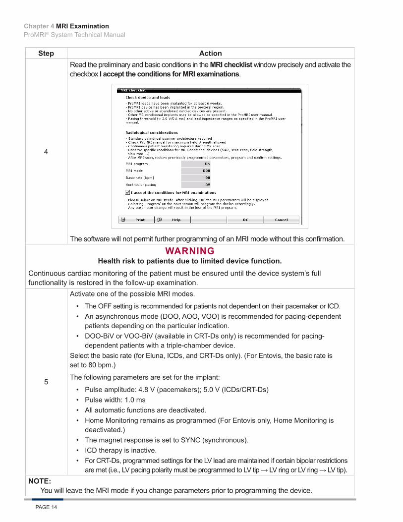
Read the preliminary and basic conditions in the MRI checklist window precisely and activate the checkbox I accept the conditions for MRI examinations.
The software will not permit further programming of an MRI mode without this confirmation.
WARNINGHealth risk to patients due to limited device function.
Continuous cardiac monitoring of the patient must be ensured until the device system’s full functionality is restored in the follow-up examination.
5
Activate one of the possible MRI modes.
• The OFF setting is recommended for patients not dependent on their pacemaker or ICD.• An asynchronous mode (DOO, AOO, VOO) is recommended for pacing-dependent
patients depending on the particular indication.• DOO-BiV or VOO-BiV (available in CRT-Ds only) is recommended for pacing-
dependent patients with a triple-chamber device.Select the basic rate (for Eluna, ICDs, and CRT-Ds only). (For Entovis, the basic rate is set to 80 bpm.)
The following parameters are set for the implant:
• Pulse amplitude: 4.8 V (pacemakers); 5.0 V (ICDs/CRT-Ds)• Pulse width: 1.0 ms• All automatic functions are deactivated.• Home Monitoring remains as programmed (For Entovis only, Home Monitoring is
deactivated.)• The magnet response is set to SYNC (synchronous).• ICD therapy is inactive.• For CRT-Ds, programmed settings for the LV lead are maintained if certain bipolar restrictions
are met (i.e., LV pacing polarity must be programmed to LV tip → LV ring or LV ring → LV tip).NOTE:
You will leave the MRI mode if you change parameters prior to programming the device.

MRI ExaminationProMRI® System Technical Manual
PAGE 15
Step Action6 Transmit the MRI mode to the implant.
NOTE:When programming the MRI mode in Entovis or Iforia, the original device settings are saved in the programmer. These settings can be accessed again during the follow-up examination after completion of the MR scan, which simplifies restoration of the status from before the MR scan. The same programmer must be used as for the preliminary examination.
For Eluna pacemakers, Iperia/Inventra ICDs, or the CRT-Ds, the original settings are stored in the device when the MRI mode is programmed. Therefore, the permanent program can be restored even when the device is interrogated by a different programmer after the MR scan.7 Print and document follow-up data (print report).
8
Finish the preliminary examination of the patient.
Several device functions may be deactivated in the MRI mode. Therefore, make sure that the patient can be scheduled for a follow-up immediately after completion of the MR scan in order to reprogram the device back to the permanent parameters as defined by the patient’s physician.
4.2 MRI Examination
4.2.1 PrerequisitesThe following conditions have to be met:
• The contraindications listed in the respective sections as well as the required MRI Conditions for Use are taken into consideration.
• The patient is previously examined by a cardiology professional.• The device is programmed to the MRI Mode, which is suitable for an MR scan.• The technical and organizational conditions are met to be able to observe the restrictions and safety
measures required during the MR scan.• Emergency equipment for resuscitation (including specialist staff certified to use it) is available.
4.2.2 Basic conditions and restrictionsThe MRI Conditions for Use (Section 3) have to be met during an MR scan and the device must be programmed to MRI Mode prior to the MR scan.
4.2.3 Patient monitoring during the MR scanThe patient should be continuously monitored during the entire MR scan, including maintaining visual and verbal contact with the patient and monitoring of blood oxygen saturation, blood pressure or ECG. Emergency equipment for resuscitation must be kept at hand and properly certified staff must be available.
If the patient exhibits signs of discomfort (i.e., warming is noted) or hemodynamic function appears to be compromised at any point during the scan, discontinue the scan and remove the patient from the MRI scanner.
4.2.4 Completion of the examinationAfter completing the MR scan, make sure the patient is monitored by a cardiology professional who performs the required follow-up cardiology examination and reprogramming of the device system.
Chapter 4

MRI ExaminationProMRI® System Technical Manual
PAGE 16
Chapter 4

Post MR Scan RequirementsProMRI® System Technical Manual
PAGE 17
5. Post MR Scan RequirementsAfter the MR scan, the patient should undergo a follow-up device interrogation. This is necessary for the patient’s safety for two reasons:
• To reprogram the device back into the original parameters.• To assess the device system for potential adverse effects caused by the MR scan.
NOTE:The device parameters during activation of the MRI mode are maintained until the MRI program is set to Off after the MR scan.
5.1 Follow-Up ProcedureAfter an MR scan, the follow-up procedure should be performed:
1. Apply the programming head.2. Interrogate the device.3. Reactivate the program that was effective prior to programming the MRI mode.4. Send the reactivated program to the device.5. Perform a complete follow-up.6. If necessary, perform further examinations.7. Print and document follow-up data (print report).8. Finish the follow-up for the patient.
Chapter 5

Post MR Scan RequirementsProMRI® System Technical Manual
PAGE 18
Chapter 5
Clinical StudyProMRI® System Technical Manual
PAGE 19
6. Clinical Study
6.1 ProMRI Phase B Clinical Study
6.1.1 Primary ObjectivesThis clinical investigation was designed to demonstrate the clinical safety of the ProMRI Pacemaker System when used under specific magnetic resonance imaging (MRI) conditions for full body MRI scan. The investigation included five primary endpoints, which condense into three main objectives:
• Primary Endpoint 1 – Evaluation of serious adverse device effect (SADE) rate related to the implanted pacing system and MRI procedure
• Primary Endpoints 2 & 3 – Evaluation of atrial and ventricular lead pacing threshold increases• Primary Endpoints 4 & 5 – Evaluation of P-wave and R-wave sensing attenuation
6.1.2 MethodsThe study enrolled subjects implanted with an Entovis family pacemaker (SR-T, DR-T) and one or two Setrox S 53 or 60 leads, and were willing to undergo an MRI scan.
The patients selected for participation were from the investigator’s general patient population meeting the indications for use of the Entovis family pacemaker system. To qualify for enrollment, subjects were required to have measurable pacing thresholds ≤ 2.0 V @ 0.4 ms and could not be implanted with other non-MRI compatible devices. Patients received a baseline evaluation at least seven days prior to the MRI procedure, at which time the pacemaker was tested and programmed to an MRI mode before the MRI, then tested and reprogramed to the original pacing mode post-MRI. The study required a cardiac or thoracic spine MRI scan.
Patients were enrolled post-implant, underwent an MRI procedure and testing, and were followed at one and three months post-MRI. During follow-up visits, a device interrogation was completed and the investigator determined if the MRI scan had any long-term effects on the function of the pacemaker system.
6.1.3 ResultsA total of 244 subjects were provisionally enrolled and 216 subjects were fully enrolled at 31 sites as of August 12, 2014. The cumulative implant duration of the 216 fully enrolled subjects at baseline and MRI procedure was 96.5 years (average implant duration of 0.45 ± 0.32 years) and 111.6 years (average implant duration of 0.52 ± 0.33), respectively. The patient follow-up compliance rate was 98.8% out of 341 required follow-ups. Endpoint data is provided for the Per Protocol (PP) and Intention-to-treat (ITT) Populations. The ITT population includes all subjects programmed to MRI mode with endpoint data from follow-up or Home Monitoring. At the time of data analysis, 199 had completed their 1-month follow-up. An additional four subjects had a missed 1-month follow-up, but are included in the ITT endpoint analysis using their Home Monitoring data. The average subject is a 68 year old male who weighs 191 pounds and is 68 inches in height.
Primary Endpoint 1The purpose of Primary Endpoint 1 was to evaluate the rate of Serious Adverse Device Effects related or possibly related to the implanted pacing system and the MRI procedure. Only SADEs that were pacing system and MRI related or possibly related, as adjudicated by the independent Data Monitoring Committee, were taken into account for calculation of the SADE rate.
Chapter 6
Clinical StudyProMRI® System Technical Manual
PAGE 20
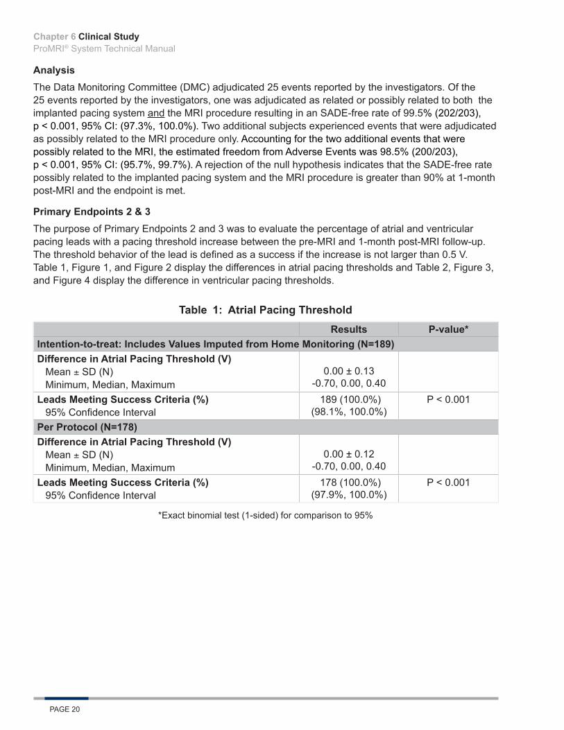
AnalysisThe Data Monitoring Committee (DMC) adjudicated 25 events reported by the investigators. Of the 25 events reported by the investigators, one was adjudicated as related or possibly related to both the implanted pacing system and the MRI procedure resulting in an SADE-free rate of 99.5% (202/203), p < 0.001, 95% CI: (97.3%, 100.0%). Two additional subjects experienced events that were adjudicated as possibly related to the MRI procedure only. Accounting for the two additional events that were possibly related to the MRI, the estimated freedom from Adverse Events was 98.5% (200/203), p < 0.001, 95% CI: (95.7%, 99.7%). A rejection of the null hypothesis indicates that the SADE-free rate possibly related to the implanted pacing system and the MRI procedure is greater than 90% at 1-month post-MRI and the endpoint is met.
Primary Endpoints 2 & 3The purpose of Primary Endpoints 2 and 3 was to evaluate the percentage of atrial and ventricular pacing leads with a pacing threshold increase between the pre-MRI and 1-month post-MRI follow-up. The threshold behavior of the lead is defined as a success if the increase is not larger than 0.5 V. Table 1, Figure 1, and Figure 2 display the differences in atrial pacing thresholds and Table 2, Figure 3, and Figure 4 display the difference in ventricular pacing thresholds.
Table 1: Atrial Pacing ThresholdResults P-value*
Intention-to-treat: Includes Values Imputed from Home Monitoring (N=189)Difference in Atrial Pacing Threshold (V)
Mean ± SD (N)Minimum, Median, Maximum
0.00 ± 0.13 -0.70, 0.00, 0.40
Leads Meeting Success Criteria (%)95% Confidence Interval
189 (100.0%) (98.1%, 100.0%)
P < 0.001
Per Protocol (N=178)Difference in Atrial Pacing Threshold (V)
Mean ± SD (N)Minimum, Median, Maximum
0.00 ± 0.12-0.70, 0.00, 0.40
Leads Meeting Success Criteria (%)95% Confidence Interval
178 (100.0%) (97.9%, 100.0%)
P < 0.001
*Exact binomial test (1-sided) for comparison to 95%
Chapter 6

Clinical StudyProMRI® System Technical Manual
PAGE 21
Figure 1: Histogram of PPP Atrial Pacing Threshold Differences (One-Month – Pre-MRI)
Figure 2: Histogram of ITT Atrial Pacing Threshold Differences (One-Month – Pre-MRI)
Atrial AnalysisThe mean threshold increase for the PP and ITT populations was 0.00 ± 0.12 V and 0.00 ± 0.13 V, respectively. Of 178 total subjects in the PP population and the 189 total subjects with data in the ITT population, all had a change in atrial pacing threshold of less than or equal to 0.5V between one-month post-MRI and pre-MRI. A rejection of the null hypothesis (p-values: PP – <0.001, ITT – <0.001) indicates that the proportion of atrial pacing threshold success is greater than 95% and Primary Endpoint 2 is met.
Chapter 6

Clinical StudyProMRI® System Technical Manual
PAGE 22
Table 2: Ventricular Pacing ThresholdResults P-value*
Intention-to-treat: Includes Values Imputed from Home Monitoring (N=199)Difference in Ventricular Pacing Threshold (V)
Mean ± SD (N)Minimum, Median, Maximum
0.00 ± 0.10 -0.30, 0.00, 0.30
Leads Meeting Success Criteria (%)95% Confidence Interval
199 (100.0%) (98.2%, 100.0%)
P <0.001
Per Protocol (N=189)Difference in Ventricular Pacing Threshold (V)
Mean ± SD (N)Minimum, Median, Maximum
0.01 ± 0.10 -0.20, 0.00, 0.30
Leads Meeting Success Criteria (%)95% Confidence Interval
189 (100.0%) (98.1%, 100.0%)
P < 0.001
*Exact binomial test (1-sided) for comparison to 95%
Figure 3: Histogram of PPP Ventricular Pacing Threshold Differences (One-Month – Pre-MRI)
Chapter 6

Clinical StudyProMRI® System Technical Manual
PAGE 23
Figure 4: Histogram of ITT Ventricular Pacing Threshold Differences (One-Month – Pre-MRI)
Ventricular AnalysisThe mean threshold increase for the PP populations was 0.01 ± 0.10 and for the ITT population was 0.00 ± 0.10. Of 189 total subjects in the PP population and the 199 total subjects with data in the ITT population, all had a change in ventricular pacing threshold of less than or equal to 0.5V between one-month post-MRI and pre-MRI, respectively. A rejection of the null hypothesis (p-values: PP – <0.001 and ITT – <0.001) indicates that the proportion of ventricular pacing threshold success is greater than 95% and Primary Endpoint 3 is met.
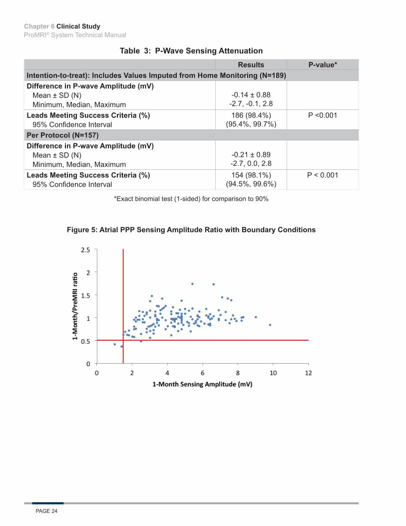
Primary Endpoints 4 & 5The purpose of Primary Endpoints 4 and 5 was to evaluate the percentage of subjects who experienced P-wave and R-wave attenuation between the pre-MRI and 1-month post-MRI follow-up. Sensing amplitude attenuation was defined as either a P-wave or R-wave amplitude decrease (between pre-MRI and one month follow-up) exceeding 50% or an amplitude at the one month follow-up of less than 1.5 mV and 5.0 mV in the atrium and ventricle, respectively. Table 3 and Table 4 display differences in atrial and ventricular sensing amplitudes over this period of time. Figure 5 and Figure 6 display the PP atrial sensing amplitude ratios with endpoint boundary conditions. Figure 7 and Figure 8 display the ITT sensing amplitude ratios with endpoint boundary conditions.
Chapter 6
Clinical StudyProMRI® System Technical Manual
PAGE 24
Table 3: P-Wave Sensing AttenuationResults P-value*
Intention-to-treat): Includes Values Imputed from Home Monitoring (N=189)Difference in P-wave Amplitude (mV)
Mean ± SD (N)Minimum, Median, Maximum
-0.14 ± 0.88-2.7, -0.1, 2.8
Leads Meeting Success Criteria (%)95% Confidence Interval
186 (98.4%) (95.4%, 99.7%)
P <0.001
Per Protocol (N=157)Difference in P-wave Amplitude (mV)
Mean ± SD (N)Minimum, Median, Maximum
-0.21 ± 0.89-2.7, 0.0, 2.8
Leads Meeting Success Criteria (%)95% Confidence Interval
154 (98.1%)(94.5%, 99.6%)
P < 0.001
*Exact binomial test (1-sided) for comparison to 90%
Figure 5: Atrial PPP Sensing Amplitude Ratio with Boundary Conditions
Chapter 6

Clinical StudyProMRI® System Technical Manual
PAGE 25
Figure 6: Atrial ITT Sensing Amplitude Ratio with Boundary Conditions
Atrial AnalysisOf 157 total subjects in the PP population and 189 total subjects with data in the ITT population, 154 (98.1%, p < 0.001) and 186 (98.4%, p < 0.001) met the endpoint for attenuation-free P-wave sensing, respectively. A rejection of the null hypothesis indicates that the P-wave attenuation free rate is greater than 90% and Primary Endpoint 4 is met.
Table 4: R-Wave Sensing AttenuationResults P-value*
Intention-to-treat: Includes Values Imputed from Home Monitoring (N=199)Difference in R-wave Amplitude (mV)
Mean ± SD (N)Minimum, Median, Maximum
-0.24 ± 1.39 -6.1, -0.1, 4.5
Leads Meeting Success Criteria (%)95% Confidence Interval
199 (100.0%) (98.2%, 100.0%)
P <0.001
Per Protocol (N=173)Difference in R-wave Amplitude (mV)
Mean ± SD (N)Minimum, Median, Maximum
-0.26 ± 1.37 -6.1, -0.1, 4.5
Leads Meeting Success Criteria (%)95% Confidence Interval
173 (100.0%)(97.9%, 100.0%)
P < 0.001
*Exact binomial test (1-sided) for comparison to 90%
Chapter 6

Clinical StudyProMRI® System Technical Manual
PAGE 26
Figure 7: Ventricular PPP Sensing Amplitude Ratio with Boundary Conditions
Figure 8: Ventricular ITT Sensing Amplitude Ratio with Boundary Conditions
Ventricular AnalysisOf the 173 subjects in the PP population and 199 subjects with data in the ITT population, all met the endpoint for attenuation-free R-wave sensing. A rejection of the null hypothesis (p-values: PP – <0.001 and ITT – <0.001) indicates that the R-wave attenuation free rate is greater than 90% and Primary Endpoint 5 was met.
Additional Data of Interest: Multiple MRI ScansSubjects both with and without indications for MRI scans could be included in the study. At least one MRI scan per subject was required in the course of the study.
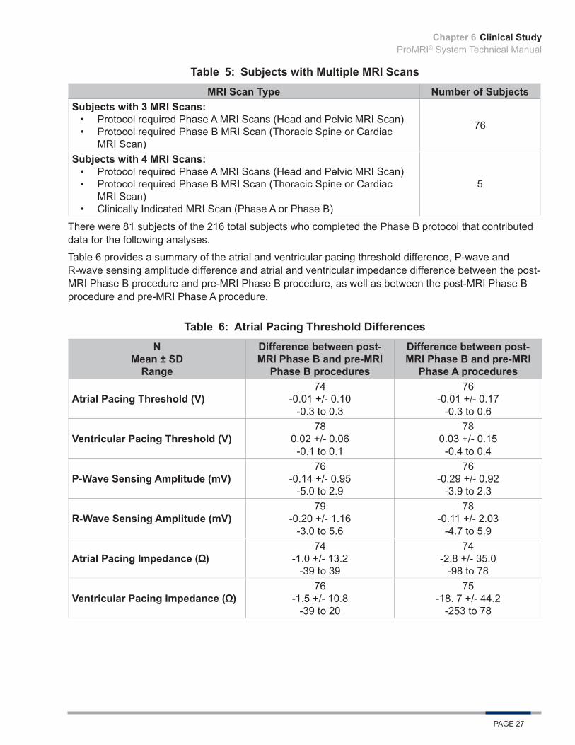
Table 5 provides the number of Phase B subjects who have undergone multiple MRI scans.
Chapter 6
Clinical StudyProMRI® System Technical Manual
PAGE 27
Table 5: Subjects with Multiple MRI ScansMRI Scan Type Number of Subjects
Subjects with 3 MRI Scans:• Protocol required Phase A MRI Scans (Head and Pelvic MRI Scan)• Protocol required Phase B MRI Scan (Thoracic Spine or Cardiac
MRI Scan)
76
Subjects with 4 MRI Scans:• Protocol required Phase A MRI Scans (Head and Pelvic MRI Scan)• Protocol required Phase B MRI Scan (Thoracic Spine or Cardiac
MRI Scan)• Clinically Indicated MRI Scan (Phase A or Phase B)
5
There were 81 subjects of the 216 total subjects who completed the Phase B protocol that contributed data for the following analyses.
Table 6 provides a summary of the atrial and ventricular pacing threshold difference, P-wave and R-wave sensing amplitude difference and atrial and ventricular impedance difference between the post-MRI Phase B procedure and pre-MRI Phase B procedure, as well as between the post-MRI Phase B procedure and pre-MRI Phase A procedure.
Table 6: Atrial Pacing Threshold DifferencesN
Mean ± SDRange
Difference between post-MRI Phase B and pre-MRI
Phase B procedures
Difference between post-MRI Phase B and pre-MRI
Phase A procedures
Atrial Pacing Threshold (V)74
-0.01 +/- 0.10-0.3 to 0.3
76-0.01 +/- 0.17
-0.3 to 0.6
Ventricular Pacing Threshold (V)78
0.02 +/- 0.06-0.1 to 0.1
780.03 +/- 0.15
-0.4 to 0.4
P-Wave Sensing Amplitude (mV)76
-0.14 +/- 0.95-5.0 to 2.9
76-0.29 +/- 0.92
-3.9 to 2.3
R-Wave Sensing Amplitude (mV)79
-0.20 +/- 1.16-3.0 to 5.6
78-0.11 +/- 2.03
-4.7 to 5.9
Atrial Pacing Impedance ( )74
-1.0 +/- 13.2-39 to 39
74-2.8 +/- 35.0
-98 to 78
Ventricular Pacing Impedance ( )76
-1.5 +/- 10.8-39 to 20
75-18. 7 +/- 44.2
-253 to 78
Chapter 6
Clinical StudyProMRI® System Technical Manual
PAGE 28
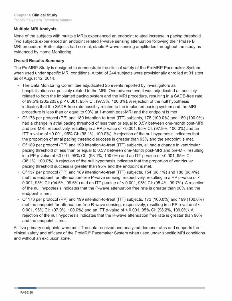
Multiple MRI AnalysisNone of the subjects with multiple MRIs experienced an endpoint related increase in pacing threshold. Two subjects experienced an endpoint related P-wave sensing attenuation following their Phase B MRI procedure. Both subjects had normal, stable P-wave sensing amplitudes throughout the study as evidenced by Home Monitoring.
Overall Results SummaryThe ProMRI® Study is designed to demonstrate the clinical safety of the ProMRI® Pacemaker System when used under specific MRI conditions. A total of 244 subjects were provisionally enrolled at 31 sites as of August 12, 2014.
• The Data Monitoring Committee adjudicated 25 events reported by investigators as hospitalizations or possibly related to the MRI. One adverse event was adjudicated as possibly related to both the implanted pacing system and the MRI procedure, resulting in a SADE-free rate of 99.5% (202/203), p < 0.001, 95% CI: (97.3%, 100.0%). A rejection of the null hypothesis indicates that the SADE-free rate possibly related to the implanted pacing system and the MRI procedure is less than or equal to 90% at 1-month post-MRI and the endpoint is met.
• Of 178 per protocol (PP) and 189 intention-to-treat (ITT) subjects, 178 (100.0%) and 189 (100.0%) had a change in atrial pacing threshold of less than or equal to 0.5V between one-month post-MRI and pre-MRI, respectively, resulting in a PP p-value of <0.001, 95% CI: (97.9%, 100.0%) and an ITT p-value of <0.001, 95% CI: (98.1%, 100.0%). A rejection of the null hypothesis indicates that the proportion of atrial pacing threshold success is greater than 95% and the endpoint is met.
• Of 189 per protocol (PP) and 199 intention-to-treat (ITT) subjects, all had a change in ventricular pacing threshold of less than or equal to 0.5V between one-Month post-MRI and pre-MRI resulting in a PP p-value of <0.001, 95% CI: (98.1%, 100.0%) and an ITT p-value of <0.001, 95% CI: (98.1%, 100.0%). A rejection of the null hypothesis indicates that the proportion of ventricular pacing threshold success is greater than 95% and the endpoint is met.
• Of 157 per protocol (PP) and 189 intention-to-treat (ITT) subjects, 154 (98.1%) and 186 (98.4%) met the endpoint for attenuation-free P-wave sensing, respectively, resulting in a PP p-value of < 0.001, 95% CI: (94.5%, 99.6%) and an ITT p-value of < 0.001, 95% CI: (95.4%, 99.7%). A rejection of the null hypothesis indicates that the P-wave attenuation free rate is greater than 90% and the endpoint is met.
• Of 173 per protocol (PP) and 199 intention-to-treat (ITT) subjects, 173 (100.0%) and 199 (100.0%) met the endpoint for attenuation-free R-wave sensing, respectively, resulting in a PP p-value of < 0.001, 95% CI: (97.9%, 100.0%) and an ITT p-value of < 0.001, 95% CI: (98.2%, 100.0%). A rejection of the null hypothesis indicates that the R-wave attenuation free rate is greater than 90% and the endpoint is met.
All five primary endpoints were met. The data received and analyzed demonstrates and supports the clinical safety and efficacy of the ProMRI® Pacemaker System when used under specific MRI conditions and without an exclusion zone.
Chapter 6
Clinical StudyProMRI® System Technical Manual
PAGE 29
6.2 ProMRI Phase C Clinical Study
6.2.1 Primary ObjectivesThis clinical investigation was designed to demonstrate the clinical safety of the ProMRI ICD System when used under specific magnetic resonance imaging (MRI) conditions for full body MRI scan. The investigation included three primary endpoints, which condense into three main objectives:
• Primary Endpoint 1 – Evaluation of serious adverse device effect (SADE) rate related to the implanted pacing system and MRI procedure
• Primary Endpoint 2 – Evaluation of ventricular lead pacing threshold increases• Primary Endpoint 3 – Evaluation of R-wave sensing attenuation
6.2.2 MethodsThe study enrolled subjects implanted with an ICD System consisting of an Iforia DR-T and Linoxsmart S 65 or Linoxsmart SD 65/18 ICD lead with a Setrox S 53 atrial lead, or Iforia VR-T DX and Linoxsmart S DX 65/15 or Linoxsmart S DX 65/17 ICD lead, and were willing to undergo an MRI scan.
The patients selected for participation were from the investigator’s general patient population meeting the indications for use of the Iforia ICD system. To qualify for enrollment, subjects were required to have measurable pacing thresholds ≤ 2.0 V @ 0.4 ms and could not be implanted with other non-MRI compatible devices. Patients received a baseline evaluation at least 7 days prior to the MRI procedure, at which time the ICD system was tested and programmed to an MRI mode before the MRI, then tested and reprogramed to the original programmed parameters post-MRI. For Phase C of the study, the protocol required cardiac or thoracic spine MRI scans.
Patients were enrolled post-implant, underwent an MRI procedure and testing, and were followed at one and three months post-MRI. During follow-up visits, a device interrogation was completed and the investigator determined if the MRI scan had any long-term effects on the function of the ICD system.
6.2.3 ResultsA total of 170 subjects were provisionally enrolled at 39 sites. There were 16 subjects that did not meet the MRI criteria or were exited prior to the MRI procedure. The remaining 154 subjects were fully enrolled and had a cumulative implant duration at the time of enrollment of 34.0 years (average implant duration of 0.22 ± 0.14 years). Endpoint data is provided for the Per Protocol (PP) and Intention-to-treat (ITT) Populations. The ITT population includes all subjects programmed to MRI mode with endpoint data from follow-up or Home Monitoring. 154 patients were programmed into the MRI mode at their MRI visit and 151 had completed their 1 month follow-up (2 subjects had a missed visit, one subject exited). The average subject is a 60 year old male who weighs 200.9 pounds and is 68.3 inches in height. The patient follow-up compliance rate was 99.3% out of 303 required follow-ups.
Primary Endpoint 1The purpose of Primary Endpoint 1 was to evaluate the rate of Serious Adverse Device Effects related or possibly related to the implanted ICD system and the MRI procedure at 1 month post-MRI. Only SADEs that were ICD system and MRI related or possibly related, as adjudicated by the independent Data Monitoring Committee, were taken into account for calculation of the SADE rate.
Chapter 6

Clinical StudyProMRI® System Technical Manual
PAGE 30
Primary Endpoint 1 AnalysisThe DMC adjudicated 52 Adverse Events reported by the investigators. Of these, none were adjudicated as related or possibly related to both the implanted pacing system and the MRI procedure resulting in an SADE-free rate of 100% (154/154), p < 0.001, 95% CI: (97.6%, 100.0%). A rejection of the null hypothesis indicates that the SADE-free rate possibly related to the implanted pacing system and the MRI procedure is greater than 90% at 1 month post-MRI and Primary Endpoint 1 was met.
Primary Endpoints 2The purpose of Primary Endpoint 2 was to evaluate the percentage of ventricular pacing leads with a pacing threshold increase between the pre-MRI and 1-month post-MRI follow-up. The threshold behavior of the lead is defined as a success if the increase is not larger than 0.5 V. Table 7 displays the ventricular pacing threshold difference between the one-month post-MRI procedure and pre-MRI procedure. Figure 9 displays a histogram of ventricular pacing threshold differences between one-month and pre MRI for the per protocol population and Figure 10 displays a histogram of the data available for ventricular pacing threshold differences for the intention-to-treat population.
Table 7: Ventricular Pacing Threshold
Group Results P-value*Intention-to-treat (ITT): Includes Values Imputed from Home Monitoring (N=154)Difference in Ventricular Pacing Threshold (V)
Mean ± SD (N) Minimum, Median, Maximum
-0.01 ± 0.12 (154)-0.40, 0.00, 0.50
% of Leads Meeting Success Criteria95% Confidence Interval
100.0% (154/154)(97.6%, 100.0%) P <0.001
Per Protocol (N=147)Difference in Ventricular Pacing Threshold (V)
Mean ± SD (N) Minimum, Median, Maximum
-0.01 ± 0.13 (147)-0.40, 0.00, 0.50
% of Leads Meeting Success Criteria95% Confidence Interval
100.0% (147/147)(97.5%, 100.0%) P <0.001
*Exact binomial test (1-sided) for comparison to 95%
Chapter 6

Clinical StudyProMRI® System Technical Manual
PAGE 31
Figure 9: Histogram of PP Ventricular Pacing Threshold Differences (One-Month – Pre-MRI)
Figure 10: Histogram of ITT Ventricular Pacing Threshold Differences (One-Month – Pre-MRI)
Primary Endpoint 2 AnalysisThe mean threshold increase for the PP and ITT population was -0.01 ± 0.13 V and -0.01 ± 0.12 V, respectively. Of 147 total subjects in the PP population and the 154 total subjects with data in the ITT population, 147 (100.0%) and 154 (100.0%) had a change in ventricular pacing threshold of less than or equal to 0.5V between one-month post-MRI and pre-MRI, respectively. A rejection of the null hypothesis (p-values: PP – <0.001 and ITT – <0.001) indicates that the proportion of ventricular pacing threshold success is greater than 95% and Primary Endpoint 2 was met.
Chapter 6
Clinical StudyProMRI® System Technical Manual
PAGE 32
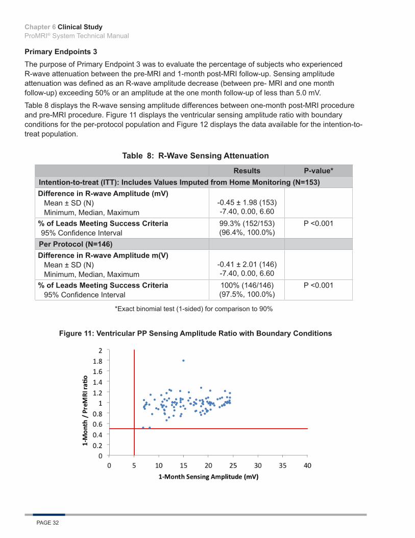
Primary Endpoints 3The purpose of Primary Endpoint 3 was to evaluate the percentage of subjects who experienced R-wave attenuation between the pre-MRI and 1-month post-MRI follow-up. Sensing amplitude attenuation was defined as an R-wave amplitude decrease (between pre- MRI and one month follow-up) exceeding 50% or an amplitude at the one month follow-up of less than 5.0 mV.
Table 8 displays the R-wave sensing amplitude differences between one-month post-MRI procedure and pre-MRI procedure. Figure 11 displays the ventricular sensing amplitude ratio with boundary conditions for the per-protocol population and Figure 12 displays the data available for the intention-to-treat population.
Table 8: R-Wave Sensing Attenuation
Results P-value*Intention-to-treat (ITT): Includes Values Imputed from Home Monitoring (N=153)Difference in R-wave Amplitude (mV)
Mean ± SD (N) Minimum, Median, Maximum
-0.45 ± 1.98 (153)-7.40, 0.00, 6.60
% of Leads Meeting Success Criteria95% Confidence Interval
99.3% (152/153)(96.4%, 100.0%)
P <0.001
Per Protocol (N=146)Difference in R-wave Amplitude m(V)
Mean ± SD (N) Minimum, Median, Maximum
-0.41 ± 2.01 (146)-7.40, 0.00, 6.60
% of Leads Meeting Success Criteria95% Confidence Interval
100% (146/146)(97.5%, 100.0%)
P <0.001
*Exact binomial test (1-sided) for comparison to 90%
Figure 11: Ventricular PP Sensing Amplitude Ratio with Boundary Conditions
Chapter 6
Clinical StudyProMRI® System Technical Manual
PAGE 33
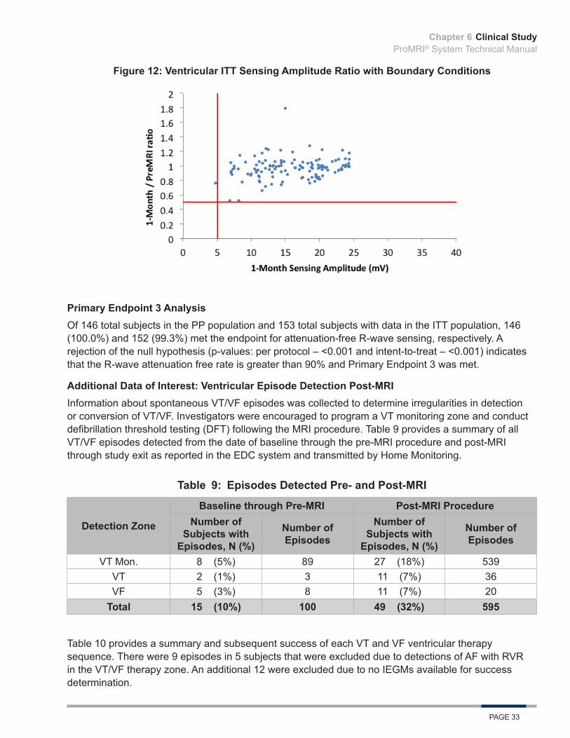
Figure 12: Ventricular ITT Sensing Amplitude Ratio with Boundary Conditions
Primary Endpoint 3 AnalysisOf 146 total subjects in the PP population and 153 total subjects with data in the ITT population, 146 (100.0%) and 152 (99.3%) met the endpoint for attenuation-free R-wave sensing, respectively. A rejection of the null hypothesis (p-values: per protocol – <0.001 and intent-to-treat – <0.001) indicates that the R-wave attenuation free rate is greater than 90% and Primary Endpoint 3 was met.
Additional Data of Interest: Ventricular Episode Detection Post-MRIInformation about spontaneous VT/VF episodes was collected to determine irregularities in detection or conversion of VT/VF. Investigators were encouraged to program a VT monitoring zone and conduct defibrillation threshold testing (DFT) following the MRI procedure. Table 9 provides a summary of all VT/VF episodes detected from the date of baseline through the pre-MRI procedure and post-MRI through study exit as reported in the EDC system and transmitted by Home Monitoring.
Table 9: Episodes Detected Pre- and Post-MRI
Detection Zone
Baseline through Pre-MRI Post-MRI ProcedureNumber of
Subjects with Episodes, N (%)
Number of Episodes
Number of Subjects with
Episodes, N (%)
Number of Episodes
VT Mon. 8 (5%) 89 27 (18%) 539VT 2 (1%) 3 11 (7%) 36VF 5 (3%) 8 11 (7%) 20
Total 15 (10%) 100 49 (32%) 595
Table 10 provides a summary and subsequent success of each VT and VF ventricular therapy sequence. There were 9 episodes in 5 subjects that were excluded due to detections of AF with RVR in the VT/VF therapy zone. An additional 12 were excluded due to no IEGMs available for success determination.
Chapter 6

Clinical StudyProMRI® System Technical Manual
PAGE 34
Table 10: Ventricular Therapy Sequences Success Detail
Therapy Sequence Subjects Episodes Successes Success Rate
ATP 8 10 10 100%ATP, Shock 2 10 10 100%Shock 1 2 2 100%ATP, Spontaneous Conversion 2 3 3 100%Spontaneous Conversion 7 10 10 100%All Therapy Sequences 13 35 35 100%
There were no adverse events reported during the study related to inadequate or delayed ICD detection or cardiac arrhythmias. No reports of over or undersensing were noted.
Ventricular Episode Detection Post-MRI AnalysisAll episode detections and therapies delivered for VT/VF episodes post-MRI (35/35, 100%) indicate that there was no delayed VT/VF detection due to the MRI procedure. Results demonstrate that the ProMRI® ICD System provides appropriate detection and effective therapy for the treatment of ventricular arrhythmias post-MRI.
Additional Data of Interest: Multiple MRI ScansSubjects both with and without indications for MRI scans may be included in the study. At least one MRI scan per subject was required in the course of the study.
There were four subjects in Phase C of ProMRI who received a clinically indicated scan in addition to their study MRI scan. Two subjects completed their clinical scan first, and two subjects first underwent their protocol required MRI scan. A clinically indicated post-MRI procedure and three month follow-up procedure were completed on the same day for two subjects.
For the subjects receiving multiple MRI procedures, Table 11, Table 12, and Table 13, respectively, display each ProMRI Phase C subject’s ventricular sensing, threshold, and impedance values at the study and clinical MRI procedures and 3-Month follow-up. In this analysis, the clinical and study MRI scans are labeled as MRI1 and MRI2 based on chronological order.
Table 11: ProMRI R-wave SensingR-wave
Sensing (mV)MRI 1 MRI 2
3-MonthPre Post Pre Post
Subject A 11.1 11.6 14 12.4 12.4Subject B 10.7 8.2 8.3 8.6 8.5Subject C 24.2 24.2 24.2 24.2 24.2Subject D 24.2 24.2 23.7 24.1 24.2
Table 12: ProMRI Ventricular Threshold
Chapter 6
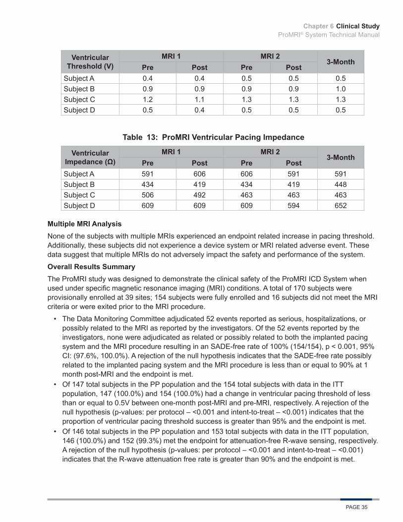
Clinical StudyProMRI® System Technical Manual
PAGE 35
Ventricular Threshold (V)
MRI 1 MRI 23-Month
Pre Post Pre PostSubject A 0.4 0.4 0.5 0.5 0.5Subject B 0.9 0.9 0.9 0.9 1.0Subject C 1.2 1.1 1.3 1.3 1.3Subject D 0.5 0.4 0.5 0.5 0.5
Table 13: ProMRI Ventricular Pacing Impedance
Ventricular Impedance (Ω)
MRI 1 MRI 23-Month
Pre Post Pre PostSubject A 591 606 606 591 591Subject B 434 419 434 419 448Subject C 506 492 463 463 463Subject D 609 609 609 594 652
Multiple MRI AnalysisNone of the subjects with multiple MRIs experienced an endpoint related increase in pacing threshold. Additionally, these subjects did not experience a device system or MRI related adverse event. These data suggest that multiple MRIs do not adversely impact the safety and performance of the system.
Overall Results SummaryThe ProMRI study was designed to demonstrate the clinical safety of the ProMRI ICD System when used under specific magnetic resonance imaging (MRI) conditions. A total of 170 subjects were provisionally enrolled at 39 sites; 154 subjects were fully enrolled and 16 subjects did not meet the MRI criteria or were exited prior to the MRI procedure.
• The Data Monitoring Committee adjudicated 52 events reported as serious, hospitalizations, or possibly related to the MRI as reported by the investigators. Of the 52 events reported by the investigators, none were adjudicated as related or possibly related to both the implanted pacing system and the MRI procedure resulting in an SADE-free rate of 100% (154/154), p < 0.001, 95% CI: (97.6%, 100.0%). A rejection of the null hypothesis indicates that the SADE-free rate possibly related to the implanted pacing system and the MRI procedure is less than or equal to 90% at 1 month post-MRI and the endpoint is met.
• Of 147 total subjects in the PP population and the 154 total subjects with data in the ITT population, 147 (100.0%) and 154 (100.0%) had a change in ventricular pacing threshold of less than or equal to 0.5V between one-month post-MRI and pre-MRI, respectively. A rejection of the null hypothesis (p-values: per protocol – <0.001 and intent-to-treat – <0.001) indicates that the proportion of ventricular pacing threshold success is greater than 95% and the endpoint is met.
• Of 146 total subjects in the PP population and 153 total subjects with data in the ITT population, 146 (100.0%) and 152 (99.3%) met the endpoint for attenuation-free R-wave sensing, respectively. A rejection of the null hypothesis (p-values: per protocol – <0.001 and intent-to-treat – <0.001) indicates that the R-wave attenuation free rate is greater than 90% and the endpoint is met.
Chapter 6

Clinical StudyProMRI® System Technical Manual
PAGE 36
• All episode detections and therapies delivered for VT/VF episodes post-MRI (35/35, 100%) indicate that there was no delayed VT/VF detection due to the MRI procedure. Results demonstrate that the ProMRI® ICD System provides appropriate detection and effective therapy for the treatment of ventricular arrhythmias post-MRI.
The data received and analyzed demonstrates and supports the clinical safety and efficacy of the ProMRI® ICD System when used under specific MRI conditions without exclusion zone. All three primary endpoints were met with statistical significance. All other additional data of interest were analyzed and support the safety and efficacy of the ProMRI ICD system.
Chapter 6

Adverse EventsProMRI® System Technical Manual
PAGE 37
7. Adverse Events
7.1 Observed Adverse Events
7.1.1 ProMRI Phase BThe ProMRI Phase B clinical study data set included 216 enrolled subjects who were programmed into MRI mode with a cumulative number of Subject-Years since enrollment of 60.77.
Adverse events were classified as serious or non-serious. Serious adverse events were defined as events that resulted in a life-threatening illness or injury, resulted in permanent impairment of body structure or function, required in-patient hospitalization, resulted in medical or surgical intervention to prevent life threatening illness or permanent impairment, or led to fetal complications.
Of the 88 adverse events (AEs) reported, there have been 18 serious adverse events (SAEs) in 18 subjects and 70 non-serious adverse events in 66 subjects. A Data Monitoring Committee adjudicated all SAEs and one adverse event was found to be possibly related to both the pacemaker system and the MRI procedure. Two events were adjudicated as possibly related to the MRI procedure.
Table 14: Summary of Serious Adverse Events
Serious Adverse Event
Subjects with Serious
Adverse Event, n
Subjects with Serious
Adverse Events, %
Serious Adverse Events,
n
Serious Adverse Events
per Subject-Year
Angina 3 1.4% 3 0.049Arrhythmia 1 0.5% 1 0.016Arterial Stenosis 2 0.9% 2 0.033
Gastrointestinal 1 0.5% 1 0.016
Infection 1 0.5% 1 0.016
Medication Related 1 0.5% 1 0.016
Musculoskeletal 2 0.9% 2 0.033
Other 5 2.3% 5 0.082
Syncope/Pre-Syncope 2 0.9% 2 0.033Total 18 8.3% 18 0.296
Number of Enrolled Subjects = 216, Number of Subject-Years since Enrollment = 60.77
Chapter 7
Adverse EventsProMRI® System Technical Manual
PAGE 38
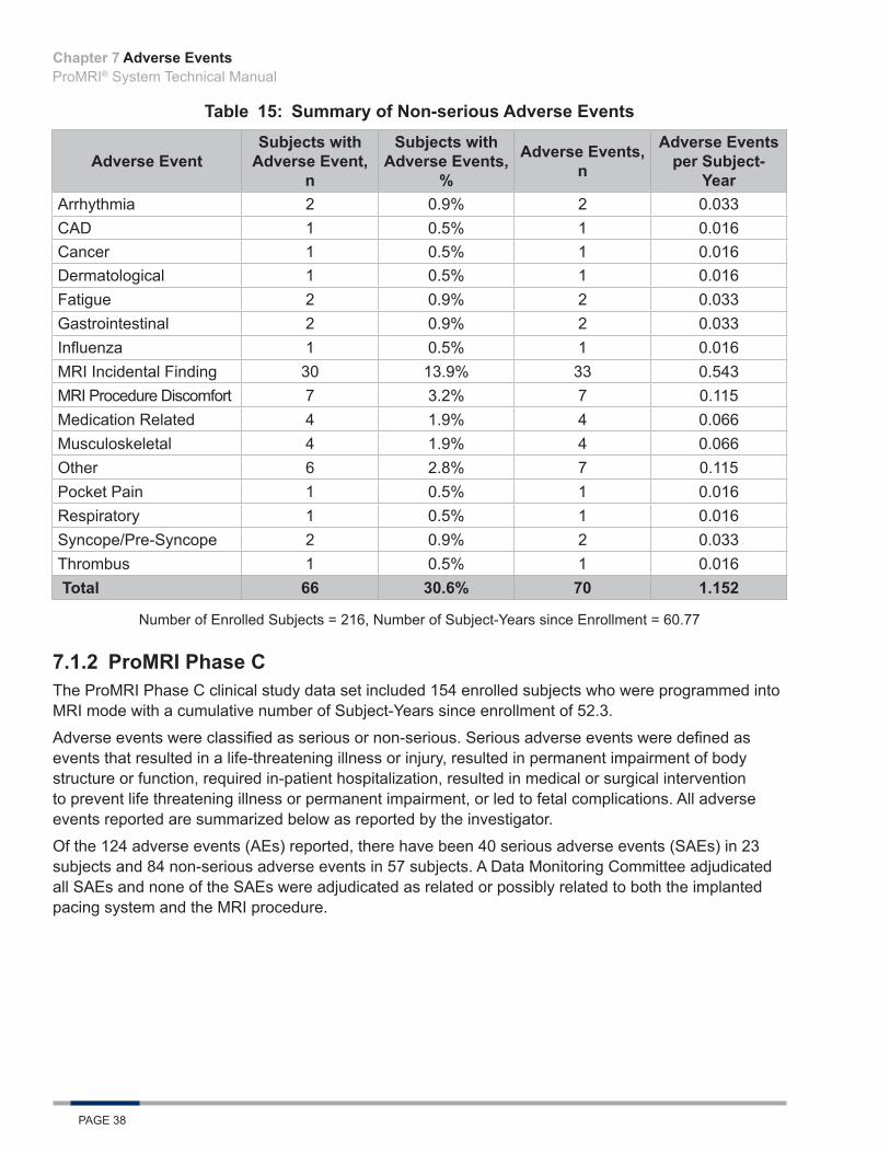
Table 15: Summary of Non-serious Adverse Events
Adverse EventSubjects with
Adverse Event, n
Subjects with Adverse Events,
%
Adverse Events, n
Adverse Events per Subject-
YearArrhythmia 2 0.9% 2 0.033CAD 1 0.5% 1 0.016Cancer 1 0.5% 1 0.016Dermatological 1 0.5% 1 0.016Fatigue 2 0.9% 2 0.033Gastrointestinal 2 0.9% 2 0.033Influenza 1 0.5% 1 0.016MRI Incidental Finding 30 13.9% 33 0.543MRI Procedure Discomfort 7 3.2% 7 0.115Medication Related 4 1.9% 4 0.066Musculoskeletal 4 1.9% 4 0.066Other 6 2.8% 7 0.115Pocket Pain 1 0.5% 1 0.016Respiratory 1 0.5% 1 0.016Syncope/Pre-Syncope 2 0.9% 2 0.033Thrombus 1 0.5% 1 0.016 Total 66 30.6% 70 1.152
Number of Enrolled Subjects = 216, Number of Subject-Years since Enrollment = 60.77
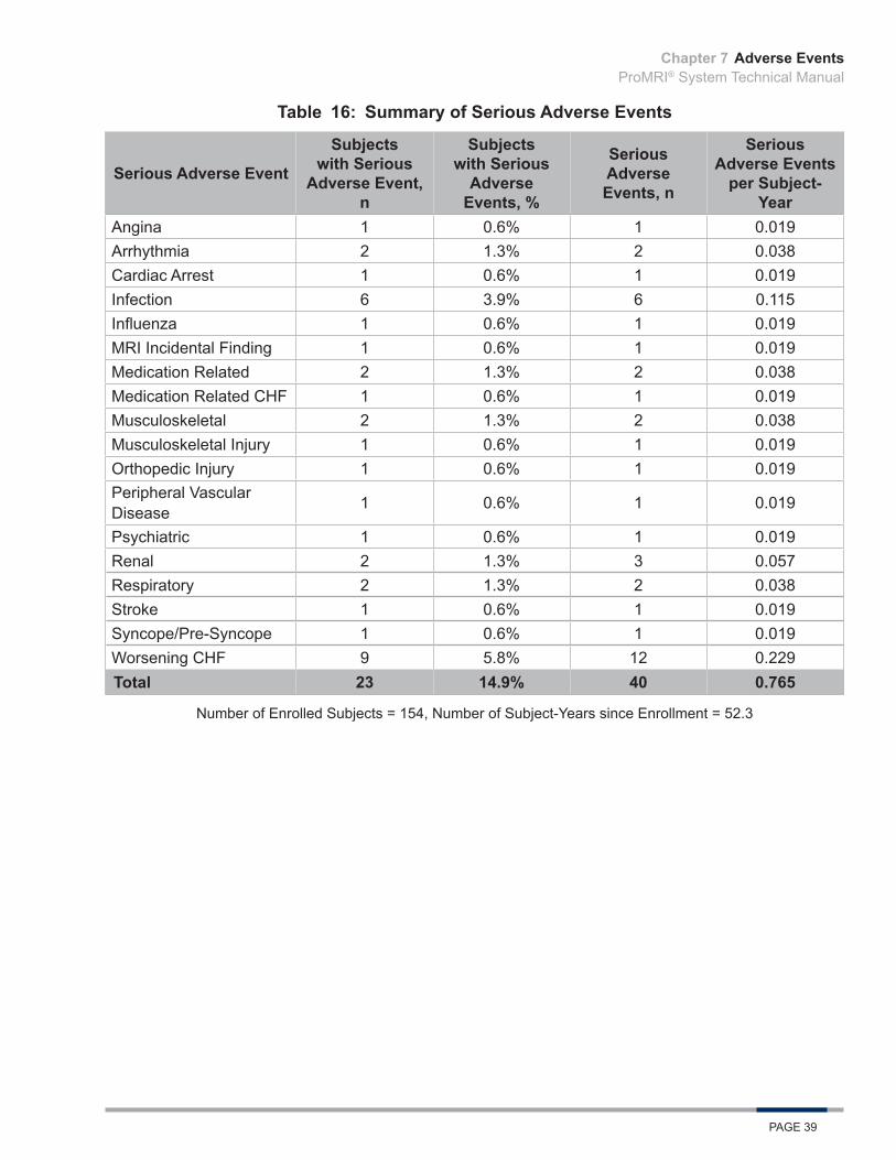
7.1.2 ProMRI Phase CThe ProMRI Phase C clinical study data set included 154 enrolled subjects who were programmed into MRI mode with a cumulative number of Subject-Years since enrollment of 52.3.
Adverse events were classified as serious or non-serious. Serious adverse events were defined as events that resulted in a life-threatening illness or injury, resulted in permanent impairment of body structure or function, required in-patient hospitalization, resulted in medical or surgical intervention to prevent life threatening illness or permanent impairment, or led to fetal complications. All adverse events reported are summarized below as reported by the investigator.
Of the 124 adverse events (AEs) reported, there have been 40 serious adverse events (SAEs) in 23 subjects and 84 non-serious adverse events in 57 subjects. A Data Monitoring Committee adjudicated all SAEs and none of the SAEs were adjudicated as related or possibly related to both the implanted pacing system and the MRI procedure.
Chapter 7
Adverse EventsProMRI® System Technical Manual
PAGE 39
Table 16: Summary of Serious Adverse Events
Serious Adverse Event
Subjects with Serious
Adverse Event, n
Subjects with Serious
Adverse Events, %
Serious Adverse Events, n
Serious Adverse Events
per Subject-Year
Angina 1 0.6% 1 0.019Arrhythmia 2 1.3% 2 0.038Cardiac Arrest 1 0.6% 1 0.019Infection 6 3.9% 6 0.115Influenza 1 0.6% 1 0.019MRI Incidental Finding 1 0.6% 1 0.019Medication Related 2 1.3% 2 0.038Medication Related CHF 1 0.6% 1 0.019Musculoskeletal 2 1.3% 2 0.038Musculoskeletal Injury 1 0.6% 1 0.019Orthopedic Injury 1 0.6% 1 0.019Peripheral Vascular Disease 1 0.6% 1 0.019
Psychiatric 1 0.6% 1 0.019Renal 2 1.3% 3 0.057Respiratory 2 1.3% 2 0.038Stroke 1 0.6% 1 0.019Syncope/Pre-Syncope 1 0.6% 1 0.019Worsening CHF 9 5.8% 12 0.229Total 23 14.9% 40 0.765
Number of Enrolled Subjects = 154, Number of Subject-Years since Enrollment = 52.3
Chapter 7

Adverse EventsProMRI® System Technical Manual
PAGE 40
Table 17: Summary of Non-serious Adverse Events
Adverse EventSubjects with
Adverse Event, n
Subjects with Adverse
Events, %
Adverse Events, n
Adverse Events per Subject-
YearArrhythmia 5 3.2% 5 0.096Device Related 2 1.3% 2 0.038Gastrointestinal 1 0.6% 1 0.019Infection 3 1.9% 3 0.057MRI Incidental Finding 24 15.6% 25 0.478MRI Procedure Discomfort 6 3.9% 6 0.115
Medication Induced CHF 1 0.6% 1 0.019Medication Related 3 1.9% 3 0.057Musculoskeletal 6 3.9% 6 0.115Neurological 1 0.6% 1 0.019Other 9 5.8% 12 0.229Other - MRI Procedure 1 0.6% 1 0.019Other - Medical 1 0.6% 1 0.019Peripheral Vascular Disease 1 0.6% 1 0.019
Pocket Pain/Discomfort 4 2.6% 5 0.096Psychiatric 1 0.6% 1 0.019Renal 1 0.6% 1 0.019Respiratory 3 1.9% 3 0.057Syncope/Pre-Syncope 1 0.6% 1 0.019Worsening CHF 5 3.2% 5 0.096Total 57 37.0% 84 1.625
Number of Enrolled Subjects = 154, Number of Subject-Years since Enrollment = 52.3
Chapter 7

ProMRI® System Technical Manual
PAGE 41

ProMRI® System Technical Manual
PAGE 42

ProMRI® System Technical Manual
PAGE 43

ProMRI® System Technical Manual
PAGE 44

ProMRI® System Technical Manual
PAGE 45
ProMRI® SystemTechnical Manual
BIOTRONIK, Inc.6024 Jean RoadLake Oswego, OR 97035-5369
(800) 547-0394 (24-hour)(800) 291-0470 (fax)www.biotronik.com
M4188-C 08/16© 2016 BIOTRONIK, Inc. All rights reserved.MN062r4 8/29/16
www.biotronikusa.com/promriManufactured by:
BIOTRONIK SE & Co. KGWoermannkehre 112359 Berlin Germany