promass 80i, 83i - access...
TRANSCRIPT

TI075D/06/en/05.10
71116468
Technical Information
Proline Promass 80I, 83ICoriolis Mass Flow Measuring System
The single-tube system with a "fit-and-forget" design: In-line
viscosity measurement – easy to clean – hygienic – does not harm
the material being measured – chemical-resistant materials
Application
The Coriolis measuring principle operates independently
of physical fluid properties, such as viscosity and density.
• Extremely accurate measurement of liquids and gases
such as oils, lubricants, fuels, liquefied gases, cleaning
agents and solvents, sterile media (blood plasma),
foodstuffs and paints
• Fluid temperatures up to +150 °C (+302 °F)
• Process pressures up to 100 bar (1450 psi)
• Mass flow measurement up to 180 t/h (6615 lb/min)
Approvals for hazardous area:
• ATEX, FM, CSA, TIIS, IECEx, NEPSI
Approvals in the food industry/hygiene sector:
• 3A, EHEDG
Connection to all common process control systems:
• HART, PROFIBUS PA/DP, FOUNDATION Fieldbus,
MODBUS
Relevant safety aspects:
• Secondary containment up to 40 bar (580 psi),
Pressure Equipment Directive, SIL-2
Your benefits
The Promass measuring devices make it possible to
simultaneously record several process variables
(mass/density/temperature/viscosity) for various
process conditions during measuring operation.
The uniform Proline transmitter concept includes:
• Modular device and operating concept resulting in a
higher degree of efficiency
• Software options for batching and concentration
measurement for extended range of application
• Diagnostic ability and data back-up for increased
process quality
The Promass sensors, tried and tested in over
100000 applications, offer:
• Multivariable flow measurement in compact design
• Insensitivity to vibrations thanks to balanced single-
tube measuring system
• Efficient protection against forces from piping thanks
to robust construction
• Easy installation without taking inlet and outlet runs
into account

Proline Promass 80I, 83I
2 Endress+Hauser
Table of contents
Function and system design. . . . . . . . . . . . . . . . . . . . . 3
Measuring principle . . . . . . . . . . . . . . . . . . . . . . . . . . . . . . . . . . . 3
Measuring system . . . . . . . . . . . . . . . . . . . . . . . . . . . . . . . . . . . . . 4
Input . . . . . . . . . . . . . . . . . . . . . . . . . . . . . . . . . . . . . . 6
Measured variable . . . . . . . . . . . . . . . . . . . . . . . . . . . . . . . . . . . . 6
Measuring range . . . . . . . . . . . . . . . . . . . . . . . . . . . . . . . . . . . . . . 6
Operable flow range . . . . . . . . . . . . . . . . . . . . . . . . . . . . . . . . . . . 7
Input signal . . . . . . . . . . . . . . . . . . . . . . . . . . . . . . . . . . . . . . . . . 7
Output . . . . . . . . . . . . . . . . . . . . . . . . . . . . . . . . . . . . . 7
Output signal . . . . . . . . . . . . . . . . . . . . . . . . . . . . . . . . . . . . . . . . 7
Signal on alarm . . . . . . . . . . . . . . . . . . . . . . . . . . . . . . . . . . . . . . 9
Load . . . . . . . . . . . . . . . . . . . . . . . . . . . . . . . . . . . . . . . . . . . . . . 9
Low flow cut off . . . . . . . . . . . . . . . . . . . . . . . . . . . . . . . . . . . . . . 9
Galvanic isolation . . . . . . . . . . . . . . . . . . . . . . . . . . . . . . . . . . . . . 9
Switching output . . . . . . . . . . . . . . . . . . . . . . . . . . . . . . . . . . . . . 9
Power supply. . . . . . . . . . . . . . . . . . . . . . . . . . . . . . . 10
Electrical connection Measuring unit . . . . . . . . . . . . . . . . . . . . . 10
Electrical connection, terminal assignment . . . . . . . . . . . . . . . . . 11
Electrical connection Remote version . . . . . . . . . . . . . . . . . . . . . 12
Supply voltage . . . . . . . . . . . . . . . . . . . . . . . . . . . . . . . . . . . . . . 12
Cable entries . . . . . . . . . . . . . . . . . . . . . . . . . . . . . . . . . . . . . . . 12
Remote version cable specifications . . . . . . . . . . . . . . . . . . . . . . . 13
Power consumption . . . . . . . . . . . . . . . . . . . . . . . . . . . . . . . . . . 13
Power supply failure . . . . . . . . . . . . . . . . . . . . . . . . . . . . . . . . . . 13
Potential equalization . . . . . . . . . . . . . . . . . . . . . . . . . . . . . . . . . 13
Performance characteristics. . . . . . . . . . . . . . . . . . . . 14
Reference operating conditions . . . . . . . . . . . . . . . . . . . . . . . . . . 14
Maximum measured error . . . . . . . . . . . . . . . . . . . . . . . . . . . . . 14
Repeatability . . . . . . . . . . . . . . . . . . . . . . . . . . . . . . . . . . . . . . . . 15
Influence of fluid temperature . . . . . . . . . . . . . . . . . . . . . . . . . . . 15
Influence of fluid pressure . . . . . . . . . . . . . . . . . . . . . . . . . . . . . . 16
Design fundamentals . . . . . . . . . . . . . . . . . . . . . . . . . . . . . . . . . 16
Operating conditions: Installation . . . . . . . . . . . . . . . 17
Installation instructions . . . . . . . . . . . . . . . . . . . . . . . . . . . . . . . . 17
Inlet and outlet runs . . . . . . . . . . . . . . . . . . . . . . . . . . . . . . . . . . 20
Length of connecting cable . . . . . . . . . . . . . . . . . . . . . . . . . . . . . 20
System pressure . . . . . . . . . . . . . . . . . . . . . . . . . . . . . . . . . . . . . 21
Operating conditions: Environment. . . . . . . . . . . . . . 21
Ambient temperature range . . . . . . . . . . . . . . . . . . . . . . . . . . . . 21
Storage temperature . . . . . . . . . . . . . . . . . . . . . . . . . . . . . . . . . . 21
Degree of protection . . . . . . . . . . . . . . . . . . . . . . . . . . . . . . . . . . 21
Shock resistance . . . . . . . . . . . . . . . . . . . . . . . . . . . . . . . . . . . . . 21
Vibration resistance . . . . . . . . . . . . . . . . . . . . . . . . . . . . . . . . . . 21
Electromagnetic compatibility (EMC) . . . . . . . . . . . . . . . . . . . . . 21
Operating conditions: Process . . . . . . . . . . . . . . . . . . 22
Fluid temperature range . . . . . . . . . . . . . . . . . . . . . . . . . . . . . . . 22
Fluid pressure range (nominal pressure) . . . . . . . . . . . . . . . . . . . 22
Limiting flow . . . . . . . . . . . . . . . . . . . . . . . . . . . . . . . . . . . . . . . 22
Pressure loss . . . . . . . . . . . . . . . . . . . . . . . . . . . . . . . . . . . . . . . . 22
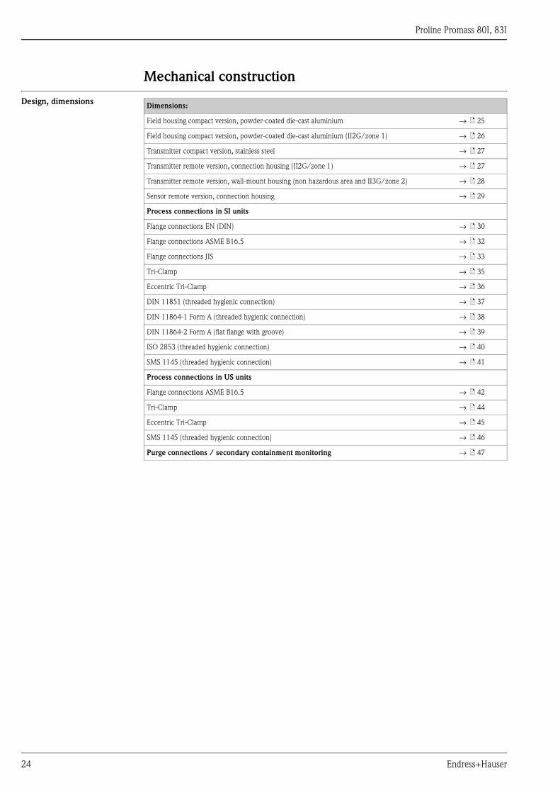
Mechanical construction . . . . . . . . . . . . . . . . . . . . . . 24
Design, dimensions . . . . . . . . . . . . . . . . . . . . . . . . . . . . . . . . . . 24
Weight . . . . . . . . . . . . . . . . . . . . . . . . . . . . . . . . . . . . . . . . . . . 48
Materials . . . . . . . . . . . . . . . . . . . . . . . . . . . . . . . . . . . . . . . . . . 48
Material load curves . . . . . . . . . . . . . . . . . . . . . . . . . . . . . . . . . . 49
Process connections . . . . . . . . . . . . . . . . . . . . . . . . . . . . . . . . . . 51
Human interface . . . . . . . . . . . . . . . . . . . . . . . . . . . . 52
Display elements . . . . . . . . . . . . . . . . . . . . . . . . . . . . . . . . . . . . 52
Operating elements . . . . . . . . . . . . . . . . . . . . . . . . . . . . . . . . . . 52
Language groups . . . . . . . . . . . . . . . . . . . . . . . . . . . . . . . . . . . . 52
Remote operation . . . . . . . . . . . . . . . . . . . . . . . . . . . . . . . . . . . . 52
Certificates and approvals . . . . . . . . . . . . . . . . . . . . . 52
CE mark . . . . . . . . . . . . . . . . . . . . . . . . . . . . . . . . . . . . . . . . . . 52
C-Tick symbol . . . . . . . . . . . . . . . . . . . . . . . . . . . . . . . . . . . . . . 52
Ex approval . . . . . . . . . . . . . . . . . . . . . . . . . . . . . . . . . . . . . . . . 52
Sanitary compatibility . . . . . . . . . . . . . . . . . . . . . . . . . . . . . . . . . 52
FOUNDATION Fieldbus certification . . . . . . . . . . . . . . . . . . . . 53
PROFIBUS DP/PA certification . . . . . . . . . . . . . . . . . . . . . . . . . 53
MODBUS certification . . . . . . . . . . . . . . . . . . . . . . . . . . . . . . . . 53
Other standards and guidelines . . . . . . . . . . . . . . . . . . . . . . . . . . 53
Pressure Equipment Directive . . . . . . . . . . . . . . . . . . . . . . . . . . 53
Functional safety . . . . . . . . . . . . . . . . . . . . . . . . . . . . . . . . . . . . 54
Ordering information. . . . . . . . . . . . . . . . . . . . . . . . . 54
Accessories . . . . . . . . . . . . . . . . . . . . . . . . . . . . . . . . 54
Documentation . . . . . . . . . . . . . . . . . . . . . . . . . . . . . 54
Registered trademarks . . . . . . . . . . . . . . . . . . . . . . . . 55
Proline Promass 80I, 83I
Endress+Hauser 3
Function and system design
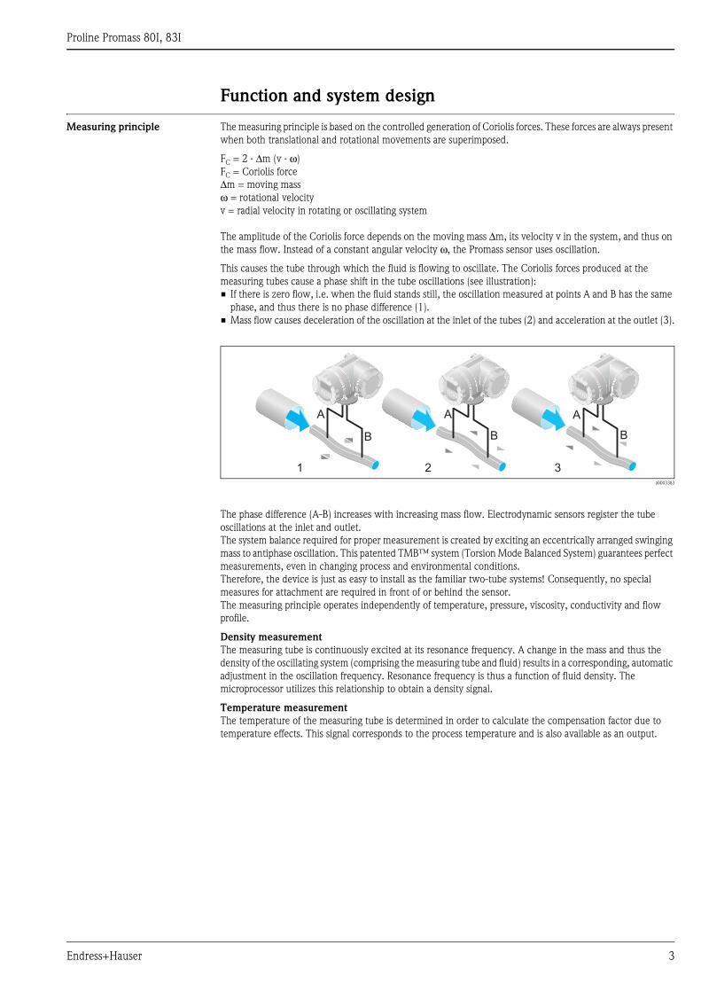
Measuring principle The measuring principle is based on the controlled generation of Coriolis forces. These forces are always present
when both translational and rotational movements are superimposed.
FC = 2 · Δm (v · ω)
FC = Coriolis force
Δm = moving mass
ω = rotational velocity
v = radial velocity in rotating or oscillating system
The amplitude of the Coriolis force depends on the moving mass Δm, its velocity v in the system, and thus on
the mass flow. Instead of a constant angular velocity ω, the Promass sensor uses oscillation.
This causes the tube through which the fluid is flowing to oscillate. The Coriolis forces produced at the
measuring tubes cause a phase shift in the tube oscillations (see illustration):
• If there is zero flow, i.e. when the fluid stands still, the oscillation measured at points A and B has the same
phase, and thus there is no phase difference (1).
• Mass flow causes deceleration of the oscillation at the inlet of the tubes (2) and acceleration at the outlet (3).
a0003383
The phase difference (A-B) increases with increasing mass flow. Electrodynamic sensors register the tube
oscillations at the inlet and outlet.
The system balance required for proper measurement is created by exciting an eccentrically arranged swinging
mass to antiphase oscillation. This patented TMB™ system (Torsion Mode Balanced System) guarantees perfect
measurements, even in changing process and environmental conditions.
Therefore, the device is just as easy to install as the familiar two-tube systems! Consequently, no special
measures for attachment are required in front of or behind the sensor.
The measuring principle operates independently of temperature, pressure, viscosity, conductivity and flow
profile.
Density measurement
The measuring tube is continuously excited at its resonance frequency. A change in the mass and thus the
density of the oscillating system (comprising the measuring tube and fluid) results in a corresponding, automatic
adjustment in the oscillation frequency. Resonance frequency is thus a function of fluid density. The
microprocessor utilizes this relationship to obtain a density signal.
Temperature measurement
The temperature of the measuring tube is determined in order to calculate the compensation factor due to
temperature effects. This signal corresponds to the process temperature and is also available as an output.
1 2 3
A
B
A
B
A
B
Proline Promass 80I, 83I
4 Endress+Hauser
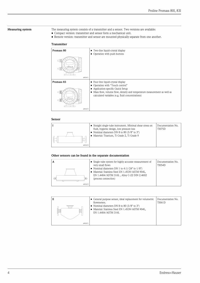
Measuring system The measuring system consists of a transmitter and a sensor. Two versions are available:
• Compact version: transmitter and sensor form a mechanical unit.
• Remote version: transmitter and sensor are mounted physically separate from one another.
Transmitter
Sensor
Other sensors can be found in the separate documentation
Promass 80
a0003671
• Two-line liquid-crystal display
• Operation with push buttons
Promass 83
a0003672
• Four-line liquid-crystal display
• Operation with “Touch control”
• Application-specific Quick Setup
• Mass flow, volume flow, density and temperature measurement as well as
calculated variables (e.g. fluid concentrations)
I
a0003678
• Straight single-tube instrument. Minimal shear stress on
fluid, hygienic design, low pressure loss
• Nominal diameters DN 8 to 80 (3/8" to 3")
• Material: Titanium, Ti Grade 2, Ti Grade 9
Documentation No.
TI075D
A
a0003679
• Single-tube system for highly accurate measurement of
very small flows
• Nominal diameters DN 1 to 4 (1/24" to 1/8")
• Material: Stainless Steel EN 1.4539/ASTM 904L,
EN 1.4404/ASTM 316L , Alloy C-22 DIN 2.4602
(process connection)
Documentation No.
TI054D
E
a0002271
• General purpose sensor, ideal replacement for volumetric
flowmeters.
• Nominal diameters DN 8 to 80 (3/8" to 3")
• Material: Stainless Steel EN 1.4539/ASTM 904L,
EN 1.4404/ASTM 316L
Documentation No.
TI061D
Esc
E- +
Esc
E+–
Proline Promass 80I, 83I
Endress+Hauser 5
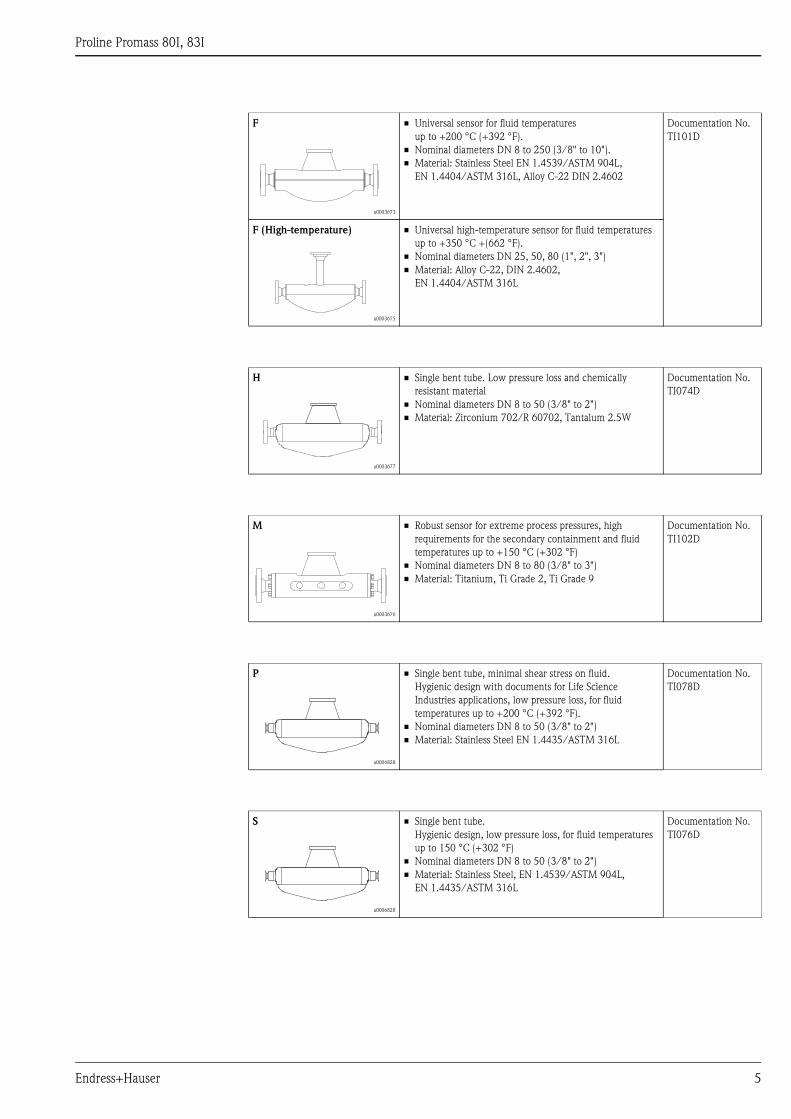
F
a0003673
• Universal sensor for fluid temperatures
up to +200 °C (+392 °F).
• Nominal diameters DN 8 to 250 (3/8" to 10").
• Material: Stainless Steel EN 1.4539/ASTM 904L,
EN 1.4404/ASTM 316L, Alloy C-22 DIN 2.4602
Documentation No.
TI101D
F (High-temperature)
a0003675
• Universal high-temperature sensor for fluid temperatures
up to +350 °C +(662 °F).
• Nominal diameters DN 25, 50, 80 (1", 2", 3")
• Material: Alloy C-22, DIN 2.4602,
EN 1.4404/ASTM 316L
H
a0003677
• Single bent tube. Low pressure loss and chemically
resistant material
• Nominal diameters DN 8 to 50 (3/8" to 2")
• Material: Zirconium 702/R 60702, Tantalum 2.5W
Documentation No.
TI074D
M
a0003676
• Robust sensor for extreme process pressures, high
requirements for the secondary containment and fluid
temperatures up to +150 °C (+302 °F)
• Nominal diameters DN 8 to 80 (3/8" to 3")
• Material: Titanium, Ti Grade 2, Ti Grade 9
Documentation No.
TI102D
P
a0006828
• Single bent tube, minimal shear stress on fluid.
Hygienic design with documents for Life Science
Industries applications, low pressure loss, for fluid
temperatures up to +200 °C (+392 °F).
• Nominal diameters DN 8 to 50 (3/8" to 2")
• Material: Stainless Steel EN 1.4435/ASTM 316L
Documentation No.
TI078D
S
a0006828
• Single bent tube.
Hygienic design, low pressure loss, for fluid temperatures
up to 150 °C (+302 °F)
• Nominal diameters DN 8 to 50 (3/8" to 2")
• Material: Stainless Steel, EN 1.4539/ASTM 904L,
EN 1.4435/ASTM 316L
Documentation No.
TI076D
Proline Promass 80I, 83I
6 Endress+Hauser
Input
Measured variable • Mass flow (proportional to the phase difference between two sensors mounted on the measuring tube to
register a phase shift in the oscillation)
• Fluid density (proportional to resonance frequency of the measuring tube)
• Fluid temperature (measured with temperature sensors)
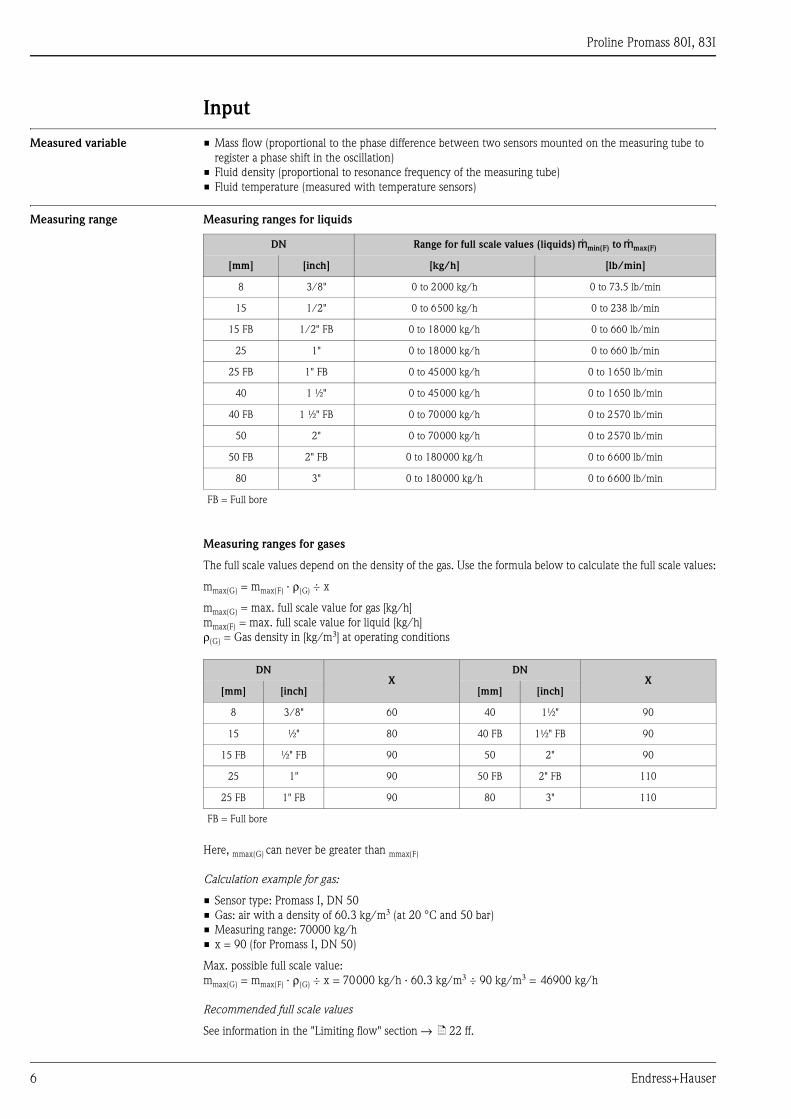
Measuring range Measuring ranges for liquids
Measuring ranges for gases
The full scale values depend on the density of the gas. Use the formula below to calculate the full scale values:
mmax(G) = mmax(F) · ρ(G) ÷ x
mmax(G) = max. full scale value for gas [kg/h]
mmax(F) = max. full scale value for liquid [kg/h]
ρ(G) = Gas density in [kg/m3] at operating conditions
Here, mmax(G) can never be greater than mmax(F)
Calculation example for gas:
• Sensor type: Promass I, DN 50
• Gas: air with a density of 60.3 kg/m3 (at 20 °C and 50 bar)
• Measuring range: 70000 kg/h
• x = 90 (for Promass I, DN 50)
Max. possible full scale value:
mmax(G) = mmax(F) · ρ(G) ÷ x = 70000 kg/h · 60.3 kg/m3 ÷ 90 kg/m3 = 46900 kg/h
Recommended full scale values
See information in the "Limiting flow" section → ä 22 ff.
DN Range for full scale values (liquids) gmin(F) to gmax(F)
[mm] [inch] [kg/h] [lb/min]
8 3/8" 0 to 2000 kg/h 0 to 73.5 lb/min
15 1/2" 0 to 6500 kg/h 0 to 238 lb/min
15 FB 1/2" FB 0 to 18000 kg/h 0 to 660 lb/min
25 1" 0 to 18000 kg/h 0 to 660 lb/min
25 FB 1" FB 0 to 45000 kg/h 0 to 1650 lb/min
40 1 ½" 0 to 45000 kg/h 0 to 1650 lb/min
40 FB 1 ½" FB 0 to 70000 kg/h 0 to 2570 lb/min
50 2" 0 to 70000 kg/h 0 to 2570 lb/min
50 FB 2" FB 0 to 180000 kg/h 0 to 6600 lb/min
80 3" 0 to 180000 kg/h 0 to 6600 lb/min
FB = Full bore
DNX
DNX
[mm] [inch] [mm] [inch]
8 3/8" 60 40 1½" 90
15 ½" 80 40 FB 1½" FB 90
15 FB ½" FB 90 50 2" 90
25 1" 90 50 FB 2" FB 110
25 FB 1" FB 90 80 3" 110
FB = Full bore

Proline Promass 80I, 83I
Endress+Hauser 7
Operable flow range Greater than 1000: 1. Flow rates above the preset full scale value do not overload the amplifier, i.e. the totalizer
values are registered correctly.
Input signal Status input (auxiliary input)
U = 3 to 30 V DC, Ri = 5 kΩ, galvanically isolated.
Configurable for: totalizer reset, positive zero return, error message reset, zero point adjustment start,
batching start/stop (optional).
Status input (auxiliary input) with PROFIBUS DP
U = 3 to 30 V DC, Ri = 3 kΩ, galvanically isolated.
Switching level: ±3 to ±30 V DC, polarity-independent.
Configurable for: positive zero return, error message reset, zero point adjustment start,
batching start/stop (optional), totalizer reset for batching (optional).
Status input (auxiliary input) with MODBUS RS485
U = 3 to 30 V DC, Ri = 3 kΩ, galvanically isolated.
Switching level: ±3 to ±30 V DC, polarity-independent.
Configurable for: totalizer reset, positive zero return, error message reset, zero point adjustment start.
Current input (only Promass 83)
Active/passive selectable, galvanically isolated, resolution: 2 μA
• Active: 4 to 20 mA, RL < 700 Ω, Uout = 24 V DC, short-circuit proof
• Passive: 0/4 to 20 mA, Ri = 150 Ω, Umax = 30 V DC
Output
Output signal Promass 80
Current output
Active/passive selectable, galvanically isolated, time constant selectable (0.05 to 100 s), full scale value
selectable, temperature coefficient: typically 0.005% o.f.s./°C, resolution: 0.5 μA
• Active: 0/4 to 20 mA, RL < 700 Ω (for HART: RL ≥ 250 Ω)
• Passive: 4 to 20 mA; supply voltage US 18 to 30 V DC; Ri ≥ 150 Ω
Pulse/frequency output
Passive, open collector, 30 V DC, 250 mA, galvanically isolated.
• Frequency output: full scale frequency 2 to 1000 Hz (fmax = 1250 Hz), on/off ratio 1:1, pulse width max. 2 s
• Pulse output: pulse value and pulse polarity selectable, pulse width configurable (0.5 to 2000 ms)
PROFIBUS PA interface:
• PROFIBUS PA in accordance with EN 50170 Volume 2, IEC 61158-2 (MBP), galvanically isolated
• Profile Version 3.0
• Current consumption: 11 mA
• Permitted supply voltage: 9 to 32 V
• Bus connection with integrated reverse polarity protection
• Error current FDE (Fault Disconnection Electronic): 0 mA
• Data transmission rate: 31.25 kBit/s
• Signal encoding: Manchester II
• Function blocks: 4 x Analog Input, 2 x Totalizer
• Output data: Mass flow, Volume flow, Density, Temperature, Totalizer
• Input data: Positive zero return (ON/OFF), Zero point adjustment, Measuring mode, Totalizer control
• Bus address can be configured via miniature switches or via the local display (optional)
Proline Promass 80I, 83I
8 Endress+Hauser
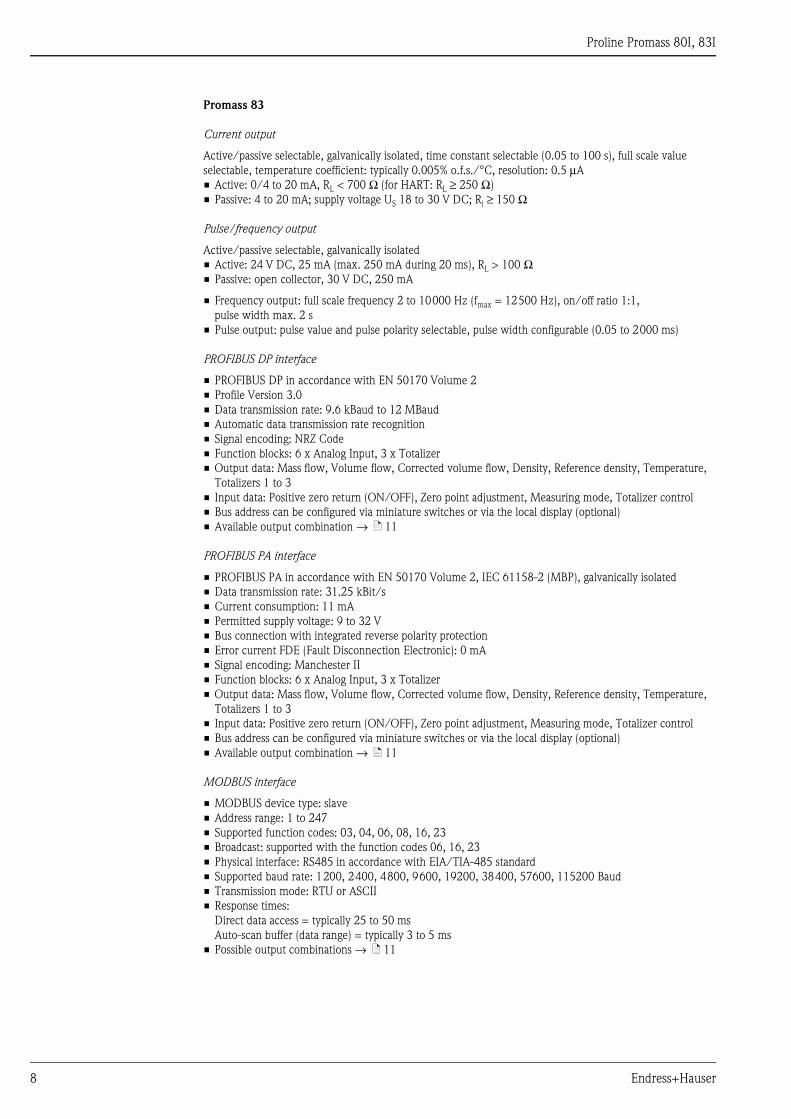
Promass 83
Current output
Active/passive selectable, galvanically isolated, time constant selectable (0.05 to 100 s), full scale value
selectable, temperature coefficient: typically 0.005% o.f.s./°C, resolution: 0.5 μA
• Active: 0/4 to 20 mA, RL < 700 Ω (for HART: RL ≥ 250 Ω)
• Passive: 4 to 20 mA; supply voltage US 18 to 30 V DC; Ri ≥ 150 Ω
Pulse/frequency output
Active/passive selectable, galvanically isolated
• Active: 24 V DC, 25 mA (max. 250 mA during 20 ms), RL > 100 Ω• Passive: open collector, 30 V DC, 250 mA
• Frequency output: full scale frequency 2 to 10000 Hz (fmax = 12500 Hz), on/off ratio 1:1,
pulse width max. 2 s
• Pulse output: pulse value and pulse polarity selectable, pulse width configurable (0.05 to 2000 ms)
PROFIBUS DP interface
• PROFIBUS DP in accordance with EN 50170 Volume 2
• Profile Version 3.0
• Data transmission rate: 9.6 kBaud to 12 MBaud
• Automatic data transmission rate recognition
• Signal encoding: NRZ Code
• Function blocks: 6 x Analog Input, 3 x Totalizer
• Output data: Mass flow, Volume flow, Corrected volume flow, Density, Reference density, Temperature,
Totalizers 1 to 3
• Input data: Positive zero return (ON/OFF), Zero point adjustment, Measuring mode, Totalizer control
• Bus address can be configured via miniature switches or via the local display (optional)
• Available output combination → ä 11
PROFIBUS PA interface
• PROFIBUS PA in accordance with EN 50170 Volume 2, IEC 61158-2 (MBP), galvanically isolated
• Data transmission rate: 31.25 kBit/s
• Current consumption: 11 mA
• Permitted supply voltage: 9 to 32 V
• Bus connection with integrated reverse polarity protection
• Error current FDE (Fault Disconnection Electronic): 0 mA
• Signal encoding: Manchester II
• Function blocks: 6 x Analog Input, 3 x Totalizer
• Output data: Mass flow, Volume flow, Corrected volume flow, Density, Reference density, Temperature,
Totalizers 1 to 3
• Input data: Positive zero return (ON/OFF), Zero point adjustment, Measuring mode, Totalizer control
• Bus address can be configured via miniature switches or via the local display (optional)
• Available output combination → ä 11
MODBUS interface
• MODBUS device type: slave
• Address range: 1 to 247
• Supported function codes: 03, 04, 06, 08, 16, 23
• Broadcast: supported with the function codes 06, 16, 23
• Physical interface: RS485 in accordance with EIA/TIA-485 standard
• Supported baud rate: 1200, 2400, 4800, 9600, 19200, 38400, 57600, 115200 Baud
• Transmission mode: RTU or ASCII
• Response times:
Direct data access = typically 25 to 50 ms
Auto-scan buffer (data range) = typically 3 to 5 ms
• Possible output combinations → ä 11
Proline Promass 80I, 83I
Endress+Hauser 9
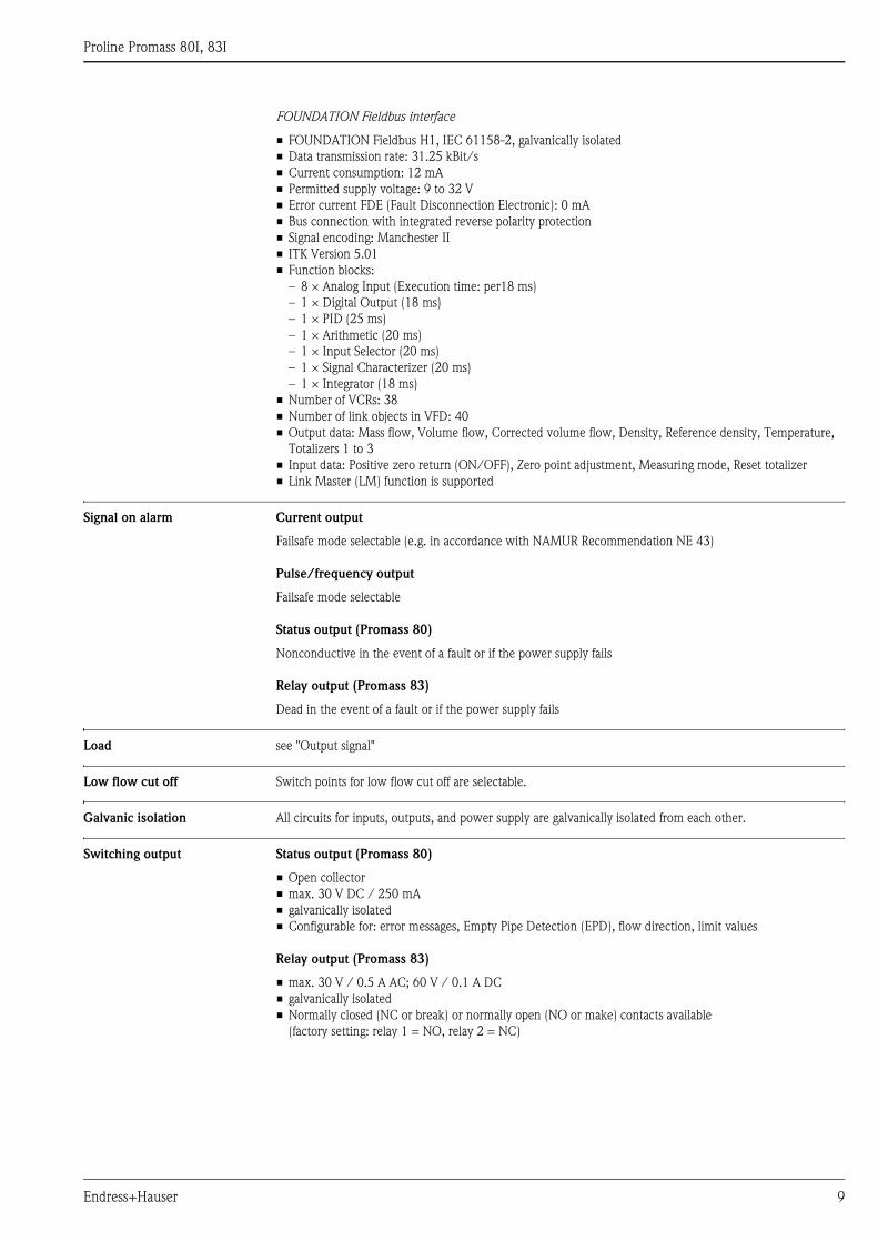
FOUNDATION Fieldbus interface
• FOUNDATION Fieldbus H1, IEC 61158-2, galvanically isolated
• Data transmission rate: 31.25 kBit/s
• Current consumption: 12 mA
• Permitted supply voltage: 9 to 32 V
• Error current FDE (Fault Disconnection Electronic): 0 mA
• Bus connection with integrated reverse polarity protection
• Signal encoding: Manchester II
• ITK Version 5.01
• Function blocks:
– 8 × Analog Input (Execution time: per18 ms)
– 1 × Digital Output (18 ms)
– 1 × PID (25 ms)
– 1 × Arithmetic (20 ms)
– 1 × Input Selector (20 ms)
– 1 × Signal Characterizer (20 ms)
– 1 × Integrator (18 ms)
• Number of VCRs: 38
• Number of link objects in VFD: 40
• Output data: Mass flow, Volume flow, Corrected volume flow, Density, Reference density, Temperature,
Totalizers 1 to 3
• Input data: Positive zero return (ON/OFF), Zero point adjustment, Measuring mode, Reset totalizer
• Link Master (LM) function is supported
Signal on alarm Current output
Failsafe mode selectable (e.g. in accordance with NAMUR Recommendation NE 43)
Pulse/frequency output
Failsafe mode selectable
Status output (Promass 80)
Nonconductive in the event of a fault or if the power supply fails
Relay output (Promass 83)
Dead in the event of a fault or if the power supply fails
Load see "Output signal"
Low flow cut off Switch points for low flow cut off are selectable.
Galvanic isolation All circuits for inputs, outputs, and power supply are galvanically isolated from each other.
Switching output Status output (Promass 80)
• Open collector
• max. 30 V DC / 250 mA
• galvanically isolated
• Configurable for: error messages, Empty Pipe Detection (EPD), flow direction, limit values
Relay output (Promass 83)
• max. 30 V / 0.5 A AC; 60 V / 0.1 A DC
• galvanically isolated
• Normally closed (NC or break) or normally open (NO or make) contacts available
(factory setting: relay 1 = NO, relay 2 = NC)
Proline Promass 80I, 83I
10 Endress+Hauser
Power supply
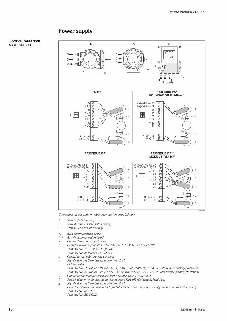
Electrical connection
Measuring unit
a0002441
Connecting the transmitter, cable cross-section: max. 2.5 mm2
A View A (field housing)
B View B (stainless steel field housing)
C View C (wall-mount housing)
*) fixed communication board
**) flexible communication board
a Connection compartment cover
b Cable for power supply: 85 to 260 V AC, 20 to 55 V AC, 16 to 62 V DC
Terminal No. 1: L1 for AC, L+ for DC
Terminal No. 2: N for AC, L– for DC
c Ground terminal for protective ground
d Signal cable: see Terminal assignment → ä 11
Fieldbus cable:
Terminal No. 26: DP (B) / PA (+) / FF (+) / MODBUS RS485 (B) / (PA, FF: with reverse polarity protection)
Terminal No. 27: DP (A) / PA (–) / FF (–) / MODBUS RS485 (A) / (PA, FF: with reverse polarity protection)
e Ground terminal for signal cable shield / fieldbus cable / RS485 line
f Service adapter for connecting service interface FXA 193 (Fieldcheck, FieldCare)
g Signal cable: see Terminal assignment → ä 11
Cable for external termination (only for PROFIBUS DP with permanent assignment communication board):
Terminal No. 24: +5 V
Terminal No. 25: DGND
aa
d
b
a
HART*
PROFIBUS DP**
MODBUS RS485**
27
25
23
21
21
26
24
22
20
L1 (L+)N (L-)
–
–
–
+
+
+
PROFIBUS PA*
FOUNDATION Fieldbus*
PA(–)/FF(–)
27
25
23
21
21
26
24
22
20
L1 (L+)N (L-)
–
–
–
+
+
+
A (RxD/TxD-N)B (RxD/TxD-P)
PA(+)/FF(+)d
c
e
b
– 27
– 25
– 23
– 21
+ 26
+ 24
+ 22
+ 20
N (L-) 2L1 (L+)1
25
23
21
21
24
22
20
L1 (L+)N (L-)
–
–
–
+
+
+
2726
A (RxD/TxD-N)B (RxD/TxD-P)
A B C
g
d
b
g
d
c
e
b
d
c
e
b
g
d
c
e
b
g
PROFIBUS DP*
(d)b d/(g)
f f
f f
Proline Promass 80I, 83I
Endress+Hauser 11
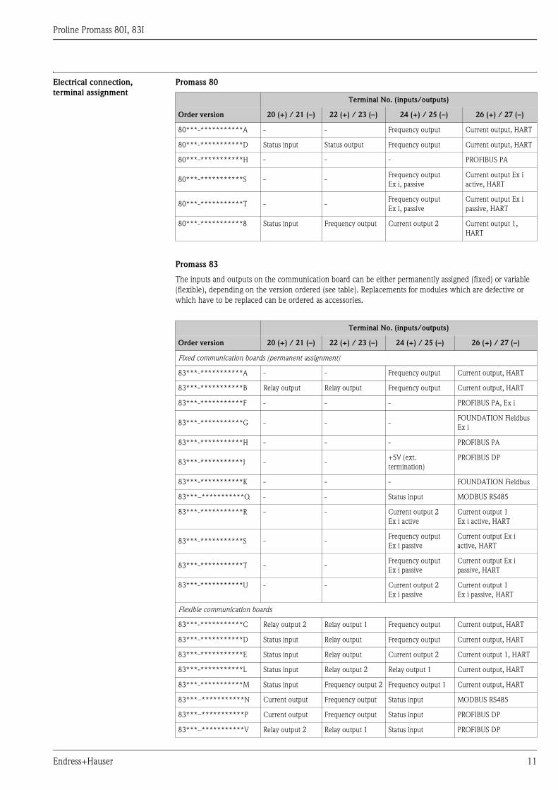
Electrical connection,
terminal assignment
Promass 80
Promass 83
The inputs and outputs on the communication board can be either permanently assigned (fixed) or variable
(flexible), depending on the version ordered (see table). Replacements for modules which are defective or
which have to be replaced can be ordered as accessories.
Terminal No. (inputs/outputs)
Order version 20 (+) / 21 (–) 22 (+) / 23 (–) 24 (+) / 25 (–) 26 (+) / 27 (–)
80***-***********A - - Frequency output Current output, HART
80***-***********D Status input Status output Frequency output Current output, HART
80***-***********H - - - PROFIBUS PA
80***-***********S - -Frequency output
Ex i, passive
Current output Ex i
active, HART
80***-***********T - -Frequency output
Ex i, passive
Current output Ex i
passive, HART
80***-***********8 Status input Frequency output Current output 2 Current output 1,
HART
Terminal No. (inputs/outputs)
Order version 20 (+) / 21 (–) 22 (+) / 23 (–) 24 (+) / 25 (–) 26 (+) / 27 (–)
Fixed communication boards (permanent assignment)
83***-***********A - - Frequency output Current output, HART
83***-***********B Relay output Relay output Frequency output Current output, HART
83***-***********F - - - PROFIBUS PA, Ex i
83***-***********G - - -FOUNDATION Fieldbus
Ex i
83***-***********H - - - PROFIBUS PA
83***-***********J - -+5V (ext.
termination)
PROFIBUS DP
83***-***********K - - - FOUNDATION Fieldbus
83***–***********Q - - Status input MODBUS RS485
83***-***********R - - Current output 2
Ex i active
Current output 1
Ex i active, HART
83***-***********S - -Frequency output
Ex i passive
Current output Ex i
active, HART
83***-***********T - -Frequency output
Ex i passive
Current output Ex i
passive, HART
83***-***********U - - Current output 2
Ex i passive
Current output 1
Ex i passive, HART
Flexible communication boards
83***-***********C Relay output 2 Relay output 1 Frequency output Current output, HART
83***-***********D Status input Relay output Frequency output Current output, HART
83***-***********E Status input Relay output Current output 2 Current output 1, HART
83***-***********L Status input Relay output 2 Relay output 1 Current output, HART
83***-***********M Status input Frequency output 2 Frequency output 1 Current output, HART
83***–***********N Current output Frequency output Status input MODBUS RS485
83***–***********P Current output Frequency output Status input PROFIBUS DP
83***–***********V Relay output 2 Relay output 1 Status input PROFIBUS DP
Proline Promass 80I, 83I
12 Endress+Hauser
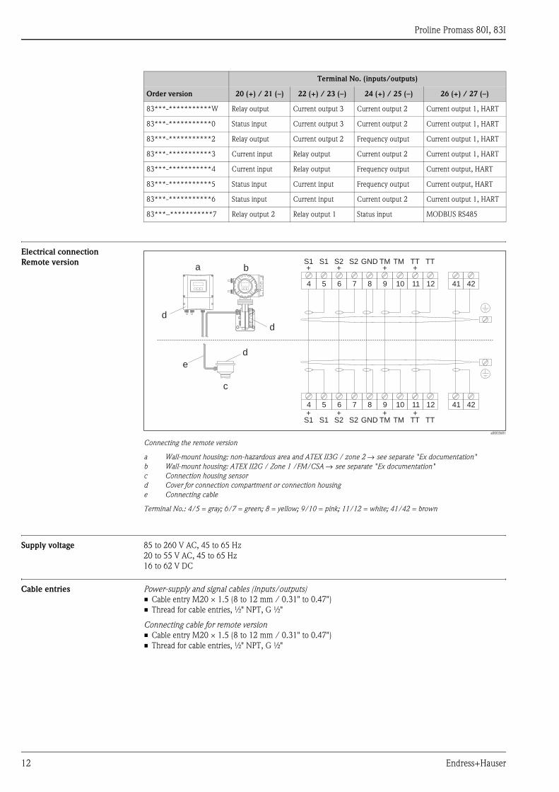
Electrical connection
Remote version
a0003681
Connecting the remote version
a Wall-mount housing: non-hazardous area and ATEX II3G / zone 2 → see separate "Ex documentation"
b Wall-mount housing: ATEX II2G / Zone 1 /FM/CSA → see separate "Ex documentation"
c Connection housing sensor
d Cover for connection compartment or connection housing
e Connecting cable
Terminal No.: 4/5 = gray; 6/7 = green; 8 = yellow; 9/10 = pink; 11/12 = white; 41/42 = brown
Supply voltage 85 to 260 V AC, 45 to 65 Hz
20 to 55 V AC, 45 to 65 Hz
16 to 62 V DC
Cable entries Power-supply and signal cables (inputs/outputs)
• Cable entry M20 × 1.5 (8 to 12 mm / 0.31" to 0.47")
• Thread for cable entries, ½" NPT, G ½"
Connecting cable for remote version
• Cable entry M20 × 1.5 (8 to 12 mm / 0.31" to 0.47")
• Thread for cable entries, ½" NPT, G ½"
83***-***********W Relay output Current output 3 Current output 2 Current output 1, HART
83***-***********0 Status input Current output 3 Current output 2 Current output 1, HART
83***-***********2 Relay output Current output 2 Frequency output Current output 1, HART
83***-***********3 Current input Relay output Current output 2 Current output 1, HART
83***-***********4 Current input Relay output Frequency output Current output, HART
83***-***********5 Status input Current input Frequency output Current output, HART
83***-***********6 Status input Current input Current output 2 Current output 1, HART
83***–***********7 Relay output 2 Relay output 1 Status input MODBUS RS485
Terminal No. (inputs/outputs)
Order version 20 (+) / 21 (–) 22 (+) / 23 (–) 24 (+) / 25 (–) 26 (+) / 27 (–)
4 5 6 7 8 9 10 11 12 41 42
4 5 6 7 8 9 10 11 12 41 42
S1 S1 S2 S2 GND TM TM TT TT+ + + +
+ + + +S1 S1 S2 S2 GND TM TM TT TT
a b
c
d
d
d
e
Proline Promass 80I, 83I
Endress+Hauser 13
Remote version cable
specifications
• 6 × 0.38 mm2 PVC cable with common shield and individually shielded cores
• Conductor resistance: ≤50 Ω/km (≤0.015 Ω/ft)
• Capacitance: core/shield: ≤420 pF/m (≤128 pF/ft)
• Cable length: max. 20 m (65 ft)
• Operating temperature: max. +105 °C (+221 °F)
Operation in zones of severe electrical interference:
The measuring device complies with the general safety requirements in accordance with EN 61010,
the EMC requirements of ICE/EN 61326, and NAMUR recommendation NE 21/43.
Power consumption AC: <15 VA (including sensor)
DC: <15 W (including sensor)
Switch-on current:
• Max. 13.5 A (< 50 ms) at 24 V DC
• Max. 3 A (< 5 ms) at 260 V AC
Power supply failure Promass 80
Lasting min. 1 power cycle:
• EEPROM saves measuring system data if the power supply fails
• HistoROM/S-DAT: exchangeable data storage chip with sensor specific data (nominal diameter,
serial number, calibration factor, zero point, etc.)
Promass 83
Lasting min. 1 power cycle:
• EEPROM and T-DAT save the measuring system data if the power supply fails.
• HistoROM/S-DAT: exchangeable data storage chip with sensor specific data (nominal diameter, serial
number, calibration factor, zero point, etc.)
Potential equalization No special measures for potential equalization are required. For instruments for use in hazardous areas, observe
the corresponding guidelines in the specific Ex documentation.
Proline Promass 80I, 83I
14 Endress+Hauser
Performance characteristics
Reference operating
conditions
• Error limits following ISO/DIN 11631
• Water, typically 20 to 30 °C (68 to 86 °F); 2 to 4 bar (30 to 60 psi)
• Data according to calibration protocol ±5 °C (±9 °F) and ±2 bar (±30 psi)
• Accuracy based on accredited calibration rigs according to ISO 17025
Maximum measured error The following values refer to the pulse/frequency output. Measured error at the current output is typically
±5 μA. Design fundamentals → ä 16.
o.r. = of reading
Mass flow and volume flow (liquids)
Promass 83I:
• ±0.10% o.r.
Promass 80I:
• ±0.15% o.r.
Mass flow (gases)
Promass 83I, 80I: ±0.50% o.r.
Density (liquids)
• ±0.0005 g/cc (under reference conditions)
• ±0.0005 g/cc (after field density calibration under process conditions)
• ±0.004 g/cc (after special density calibration)
• ±0.02 g/cc (over the entire measuring range of the sensor)
1 g/cc = 1 kg/l
Special density calibration (optional):
• Calibration range: 0.0 to 1.8 g/cc, +10 to +80 °C (+50 to +176 °F)
• Operation range : 0.0 to 5.0 g/cc, –50 to +150 °C (–58 to +302 °F)
Temperature
±0.5 °C ± 0.005 · T °C
(±1 °F ± 0.003 · (T - 32) °F)
T = medium temperature
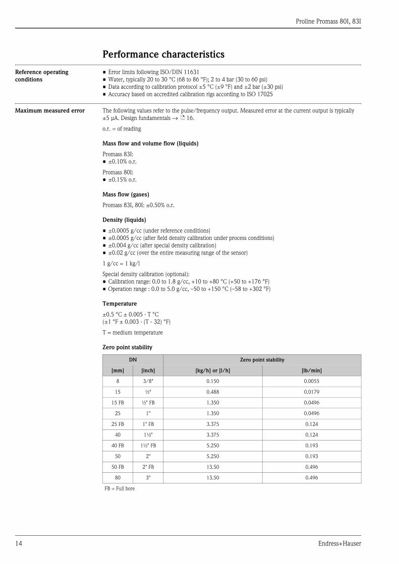
Zero point stability
DN Zero point stability
[mm] [inch] [kg/h] or [l/h] [lb/min]
8 3/8" 0.150 0.0055
15 ½" 0.488 0.0179
15 FB ½" FB 1.350 0.0496
25 1" 1.350 0.0496
25 FB 1" FB 3.375 0.124
40 1½" 3.375 0.124
40 FB 1½" FB 5.250 0.193
50 2" 5.250 0.193
50 FB 2" FB 13.50 0.496
80 3" 13.50 0.496
FB = Full bore
Proline Promass 80I, 83I
Endress+Hauser 15
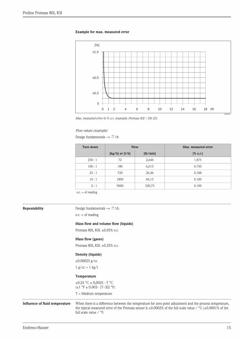
Example for max. measured error
a0004611
Max. measured error in % o.r. (example: Promass 83I / DN 25)
Flow values (example)
Design fundamentals → ä 16
Repeatability Design fundamentals → ä 16.
o.r. = of reading
Mass flow and volume flow (liquids)
Promass 80I, 83I: ±0.05% o.r.
Mass flow (gases)
Promass 80I, 83I: ±0.25% o.r.
Density (liquids)
±0.00025 g/cc
1 g/cc = 1 kg/l
Temperature
±0.25 °C ± 0,0025 · T °C
(±1 °F ± 0.003 · (T–32) °F)
T = Medium temperature
Influence of fluid temperature When there is a difference between the temperature for zero point adjustment and the process temperature,
the typical measured error of the Promass sensor is ±0.0002% of the full scale value / °C (±0.0001% of the
full scale value / °F.
0
±0.5
±0.2
±1.0
[%]
0 1 2 4 6 8 10 12 14 16 18 t/h
Turn down Flow Max. measured error
[kg/h] or [l/h] [lb/min] [% o.r.]
250 : 1 72 2,646 1.875
100 : 1 180 6,615 0.750
25 : 1 720 26,46 0.188
10 : 1 1800 66,15 0.100
2 : 1 9000 330,75 0.100
o.r. = of reading
Proline Promass 80I, 83I
16 Endress+Hauser
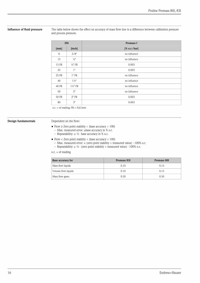
Influence of fluid pressure The table below shows the effect on accuracy of mass flow due to a difference between calibration pressure
and process pressure.
Design fundamentals Dependent on the flow:
• Flow ≥ Zero point stability ÷ (base accuracy ÷ 100)
– Max. measured error: ±base accuracy in % o.r.
– Repeatability: ± ½ · base accuracy in % o.r.
• Flow < Zero point stability ÷ (base accuracy ÷ 100)
– Max. measured error: ± (zero point stability ÷ measured value) · 100% o.r.
– Repeatability: ± ½ · (zero point stability ÷ measured value) · 100% o.r.
o.r. = of reading
DN Promass I
[mm] [inch] [% o.r./bar]
8 3/8" no influence
15 ½" no influence
15 FB ½" FB 0.003
25 1" 0.003
25 FB 1" FB no influence
40 1½" no influence
40 FB 1½" FB no influence
50 2" no influence
50 FB 2" FB 0.003
80 3" 0.003
o.r. = of reading; FB = Full bore
Base accuracy for Promass 83I Promass 80I
Mass flow liquids 0.10 0.15
Volume flow liquids 0.10 0.15
Mass flow gases 0.50 0.50
Proline Promass 80I, 83I
Endress+Hauser 17
Operating conditions: Installation
Installation instructions Note the following points:
• No special measures such as supports are necessary. External forces are absorbed by the construction of the
instrument, for example the secondary containment.
• The high oscillation frequency of the measuring tubes ensures that the correct operation of the measuring
system is not influenced by pipe vibrations.
• No special precautions need to be taken for fittings which create turbulence (valves, elbows, T-pieces etc.),
as long as no cavitation occurs.
• For mechanical reasons and to protect the pipe, support is recommended for heavy sensors.
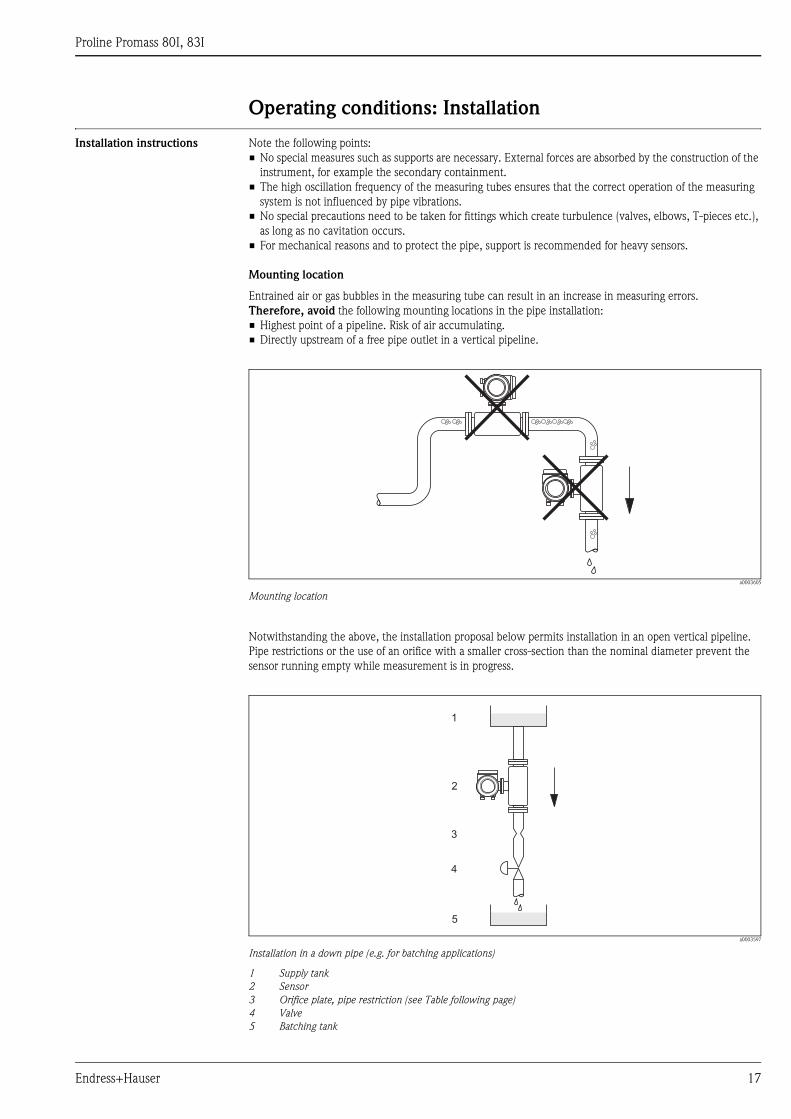
Mounting location
Entrained air or gas bubbles in the measuring tube can result in an increase in measuring errors.
Therefore, avoid the following mounting locations in the pipe installation:
• Highest point of a pipeline. Risk of air accumulating.
• Directly upstream of a free pipe outlet in a vertical pipeline.
a0003605
Mounting location
Notwithstanding the above, the installation proposal below permits installation in an open vertical pipeline.
Pipe restrictions or the use of an orifice with a smaller cross-section than the nominal diameter prevent the
sensor running empty while measurement is in progress.
a0003597
Installation in a down pipe (e.g. for batching applications)
1 Supply tank
2 Sensor
3 Orifice plate, pipe restriction (see Table following page)
4 Valve
5 Batching tank
1
2
3
4
5
Proline Promass 80I, 83I
18 Endress+Hauser
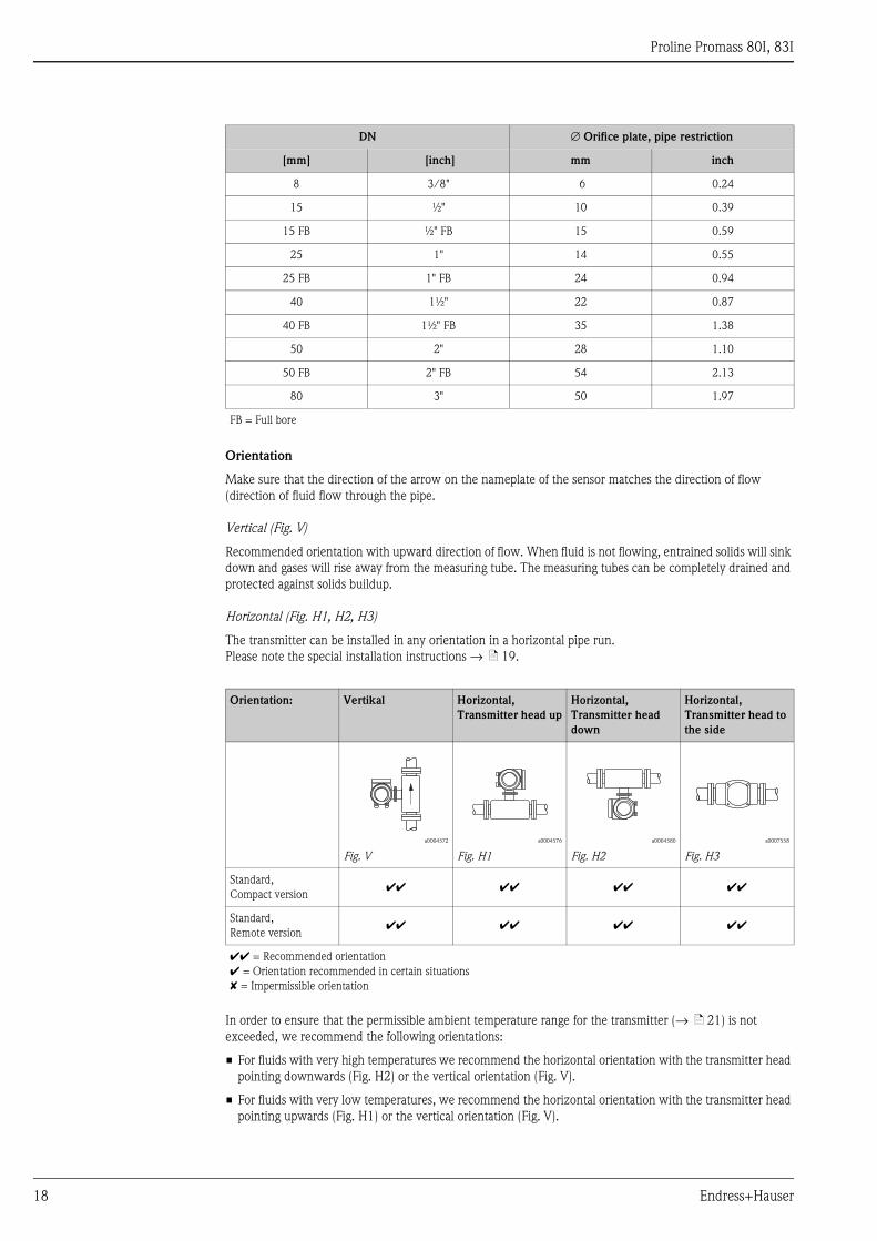
Orientation
Make sure that the direction of the arrow on the nameplate of the sensor matches the direction of flow
(direction of fluid flow through the pipe.
Vertical (Fig. V)
Recommended orientation with upward direction of flow. When fluid is not flowing, entrained solids will sink
down and gases will rise away from the measuring tube. The measuring tubes can be completely drained and
protected against solids buildup.
Horizontal (Fig. H1, H2, H3)
The transmitter can be installed in any orientation in a horizontal pipe run.
Please note the special installation instructions → ä 19.
In order to ensure that the permissible ambient temperature range for the transmitter (→ ä 21) is not
exceeded, we recommend the following orientations:
• For fluids with very high temperatures we recommend the horizontal orientation with the transmitter head
pointing downwards (Fig. H2) or the vertical orientation (Fig. V).
• For fluids with very low temperatures, we recommend the horizontal orientation with the transmitter head
pointing upwards (Fig. H1) or the vertical orientation (Fig. V).
DN ∅ Orifice plate, pipe restriction
[mm] [inch] mm inch
8 3/8" 6 0.24
15 ½" 10 0.39
15 FB ½" FB 15 0.59
25 1" 14 0.55
25 FB 1" FB 24 0.94
40 1½" 22 0.87
40 FB 1½" FB 35 1.38
50 2" 28 1.10
50 FB 2" FB 54 2.13
80 3" 50 1.97
FB = Full bore
Orientation: Vertikal Horizontal,
Transmitter head up
Horizontal,
Transmitter head
down
Horizontal,
Transmitter head to
the side
a0004572
Fig. V
a0004576
Fig. H1
a0004580
Fig. H2
a0007558
Fig. H3
Standard,
Compact versionÃÃ ÃÃ ÃÃ ÃÃ
Standard,
Remote versionÃÃ ÃÃ ÃÃ ÃÃ
ÃÃ = Recommended orientation
à = Orientation recommended in certain situations
✘ = Impermissible orientation
Proline Promass 80I, 83I
Endress+Hauser 19
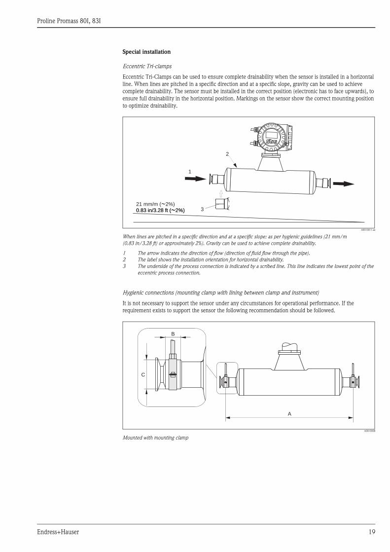
Special installation
Eccentric Tri-clamps
Eccentric Tri-Clamps can be used to ensure complete drainability when the sensor is installed in a horizontal
line. When lines are pitched in a specific direction and at a specific slope, gravity can be used to achieve
complete drainability. The sensor must be installed in the correct position (electronic has to face upwards), to
ensure full drainability in the horizontal position. Markings on the sensor show the correct mounting position
to optimize drainability.
A0010011-ae
When lines are pitched in a specific direction and at a specific slope: as per hygienic guidelines (21 mm/m
(0.83 in/3.28 ft) or approximately 2%). Gravity can be used to achieve complete drainability.
1 The arrow indicates the direction of flow (direction of fluid flow through the pipe).
2 The label shows the installation orientation for horizontal drainability.
3 The underside of the process connection is indicated by a scribed line. This line indicates the lowest point of the
eccentric process connection.
Hygienic connections (mounting clamp with lining between clamp and instrument)
It is not necessary to support the sensor under any circumstances for operational performance. If the
requirement exists to support the sensor the following recommendation should be followed.
A0010008
Mounted with mounting clamp
EscEsc
E- +
1
2
321 mm/m ( 2%)�0.83 in/3.28 ft ( 2%)�0.83 in/3.28 ft ( 2%)�
B
C
A
Proline Promass 80I, 83I
20 Endress+Hauser
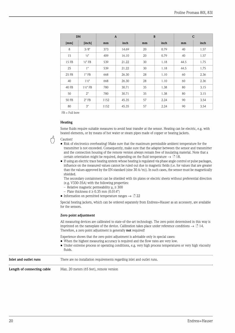
Heating
Some fluids require suitable measures to avoid heat transfer at the sensor. Heating can be electric, e.g. with
heated elements, or by means of hot water or steam pipes made of copper or heating jackets.
" Caution!
• Risk of electronics overheating! Make sure that the maximum permissible ambient temperature for the
transmitter is not exceeded. Consequently, make sure that the adapter between the sensor and transmitter
and the connection housing of the remote version always remain free of insulating material. Note that a
certain orientation might be required, depending on the fluid temperature → ä 18.
• If using an electric trace heating system whose heating is regulated via phase angle control or pulse packages,
influence on the measured values cannot be ruled out due to magnetic fields (i.e. for values that are greater
than the values approved by the EN standard (sine 30 A/m)). In such cases, the sensor must be magnetically
shielded.
The secondary containment can be shielded with tin plates or electric sheets without preferential direction
(e.g. V330-35A) with the following properties:
– Relative magnetic permeability μr ≥ 300
– Plate thickness d ≥ 0.35 mm (0.014")
• Information on permitted temperature ranges → ä 22
Special heating jackets, which can be ordered separately from Endress+Hauser as an accessory, are available
for the sensors.
Zero point adjustment
All measuring devices are calibrated to state-of-the-art technology. The zero point determined in this way is
imprinted on the nameplate of the device. Calibration takes place under reference conditions → ä 14.
Therefore, a zero point adjustment is generally not required!
Experience shows that the zero point adjustment is advisable only in special cases:
• When the highest measuring accuracy is required and the flow rates are very low.
• Under extreme process or operating conditions, e.g. very high process temperatures or very high viscosity
fluids.
Inlet and outlet runs There are no installation requirements regarding inlet and outlet runs.
Length of connecting cable Max. 20 meters (65 feet), remote version
DN A B C
[mm] [inch] mm inch mm inch mm inch
8 3/8" 373 14.69 20 0.79 40 1.57
15 ½" 409 16.10 20 0.79 40 1.57
15 FB ½" FB 539 21.22 30 1.18 44.5 1.75
25 1" 539 21.22 30 1.18 44.5 1.75
25 FB 1" FB 668 26.30 28 1.10 60 2.36
40 1½" 668 26.30 28 1.10 60 2.36
40 FB 1½" FB 780 30.71 35 1.38 80 3.15
50 2" 780 30.71 35 1.38 80 3.15
50 FB 2" FB 1152 45.35 57 2.24 90 3.54
80 3" 1152 45.35 57 2.24 90 3.54
FB = Full bore
Proline Promass 80I, 83I
Endress+Hauser 21
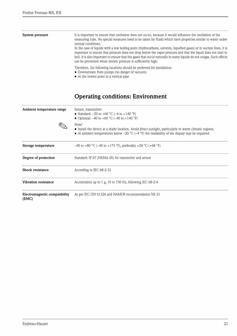
System pressure It is important to ensure that cavitation does not occur, because it would influence the oscillation of the
measuring tube. No special measures need to be taken for fluids which have properties similar to water under
normal conditions.
In the case of liquids with a low boiling point (hydrocarbons, solvents, liquefied gases) or in suction lines, it is
important to ensure that pressure does not drop below the vapor pressure and that the liquid does not start to
boil. It is also important to ensure that the gases that occur naturally in many liquids do not outgas. Such effects
can be prevented when system pressure is sufficiently high.
Therefore, the following locations should be preferred for installation:
• Downstream from pumps (no danger of vacuum)
• At the lowest point in a vertical pipe
Operating conditions: Environment
Ambient temperature range Sensor, transmitter:
• Standard: –20 to +60 °C (–4 to +140 °F)
• Optional: –40 to +60 °C (–40 to +140 °F)
! Note!
• Install the device at a shady location. Avoid direct sunlight, particularly in warm climatic regions.
• At ambient temperatures below –20 °C (–4 °F) the readability of the display may be impaired.
Storage temperature –40 to +80 °C (–40 to +175 °F), preferably +20 °C (+68 °F)
Degree of protection Standard: IP 67 (NEMA 4X) for transmitter and sensor
Shock resistance According to IEC 68-2-31
Vibration resistance Acceleration up to 1 g, 10 to 150 Hz, following IEC 68-2-6
Electromagnetic compatibility
(EMC)
As per IEC/EN 61326 and NAMUR recommendation NE 21
Proline Promass 80I, 83I
22 Endress+Hauser
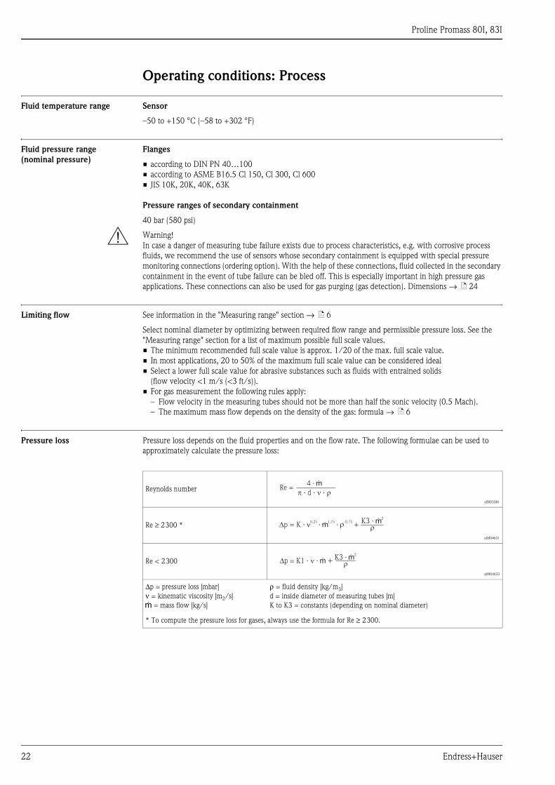
Operating conditions: Process
Fluid temperature range Sensor
–50 to +150 °C (–58 to +302 °F)
Fluid pressure range
(nominal pressure)
Flanges
• according to DIN PN 40…100
• according to ASME B16.5 Cl 150, Cl 300, Cl 600
• JIS 10K, 20K, 40K, 63K
Pressure ranges of secondary containment
40 bar (580 psi)
# Warning!
In case a danger of measuring tube failure exists due to process characteristics, e.g. with corrosive process
fluids, we recommend the use of sensors whose secondary containment is equipped with special pressure
monitoring connections (ordering option). With the help of these connections, fluid collected in the secondary
containment in the event of tube failure can be bled off. This is especially important in high pressure gas
applications. These connections can also be used for gas purging (gas detection). Dimensions → ä 24
Limiting flow See information in the "Measuring range" section → ä 6
Select nominal diameter by optimizing between required flow range and permissible pressure loss. See the
"Measuring range" section for a list of maximum possible full scale values.
• The minimum recommended full scale value is approx. 1/20 of the max. full scale value.
• In most applications, 20 to 50% of the maximum full scale value can be considered ideal
• Select a lower full scale value for abrasive substances such as fluids with entrained solids
(flow velocity <1 m/s (<3 ft/s)).
• For gas measurement the following rules apply:
– Flow velocity in the measuring tubes should not be more than half the sonic velocity (0.5 Mach).
– The maximum mass flow depends on the density of the gas: formula → ä 6
Pressure loss Pressure loss depends on the fluid properties and on the flow rate. The following formulae can be used to
approximately calculate the pressure loss:
Reynolds number
a0003381
Re ≥ 2300 *
a0004631
Re < 2300
a0004633
Δp = pressure loss [mbar]
ν = kinematic viscosity [m2/s]
g = mass flow [kg/s]
ρ = fluid density [kg/m3]
d = inside diameter of measuring tubes [m]
K to K3 = constants (depending on nominal diameter)
* To compute the pressure loss for gases, always use the formula for Re ≥ 2300.
Re =� � �· d · ·
4 · g
K3 · g2
�+�0.25
· g1.75
·-0.75
� �
�p = K1 · · g�K3 · g
2
�+
Proline Promass 80I, 83I
Endress+Hauser 23
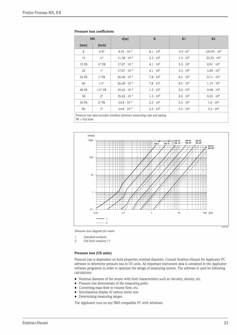
Pressure loss coefficients
a0004608
Pressure loss diagram for water
1 Standard versions
2 Full bore versions (*)
Pressure loss (US units)
Pressure loss is dependent on fluid properties nominal diameter. Consult Endress+Hauser for Applicator PC
software to determine pressure loss in US units. All important instrument data is contained in the Applicator
software programm in order to optimize the design of measuring system. The software is used for following
calculations:
• Nominal diameter of the sensor with fluid characteristics such as viscosity, density, etc.
• Pressure loss downstream of the measuring point.
• Converting mass flow to volume flow, etc.
• Simultaneous display of various meter size.
• Determining measuring ranges.
The Applicator runs on any IBM compatible PC with windows.
DN d[m] K K1 K3
[mm] [inch]
8 3/8" 8.55 ⋅ 10–3 8.1 ⋅ 106 3.9 ⋅107 129.95 ⋅ 104
15 ½" 11.38 ⋅ 10–3 2.3 ⋅ 106 1.3 ⋅ 107 23.33 ⋅ 104
15 FB ½" FB 17.07 ⋅ 10–3 4.1 ⋅ 105 3.3 ⋅ 106 0.01 ⋅ 104
25 1" 17.07 ⋅ 10–3 4.1 ⋅ 105 3.3 ⋅ 106 5.89 ⋅ 104
25 FB 1" FB 26.40 ⋅ 10–3 7.8 ⋅ 104 8.5 ⋅ 105 0.11 ⋅ 104
40 1½" 26.40 ⋅ 10–3 7.8 ⋅ 104 8.5 ⋅ 105 1.19 ⋅ 104
40 FB 1½" FB 35.62 ⋅ 10–3 1.3 ⋅ 104 2.0 ⋅ 105 0.08 ⋅ 104
50 2" 35.62 ⋅ 10–3 1.3 ⋅ 104 2.0 ⋅ 105 0.25 ⋅ 104
50 FB 2" FB 54.8 ⋅ 10–3 2.3 ⋅ 103 5.5 ⋅ 104 1.0 ⋅ 102
80 3" 54.8 ⋅ 10–3 2.3 ⋅ 103 5.5 ⋅ 104 3.5 ⋅ 102
Pressure loss data includes interface between measuring tube and piping
FB = Full bore
1000
100
10
1
0.1
0.01 0.1 1 10 100
DN 40
DN 25 *
DN 50
DN 40 *
DN 25
DN 15 *DN 15
[mbar]
[t/h]
1
DN 8
DN 80
DN 50 *
2
Proline Promass 80I, 83I
24 Endress+Hauser
Mechanical construction
Design, dimensionsDimensions:
Field housing compact version, powder-coated die-cast aluminium → ä 25
Field housing compact version, powder-coated die-cast aluminium (II2G/zone 1) → ä 26
Transmitter compact version, stainless steel → ä 27
Transmitter remote version, connection housing (II2G/zone 1) → ä 27
Transmitter remote version, wall-mount housing (non hazardous area and II3G/zone 2) → ä 28
Sensor remote version, connection housing → ä 29
Process connections in SI units
Flange connections EN (DIN) → ä 30
Flange connections ASME B16.5 → ä 32
Flange connections JIS → ä 33
Tri-Clamp → ä 35
Eccentric Tri-Clamp → ä 36
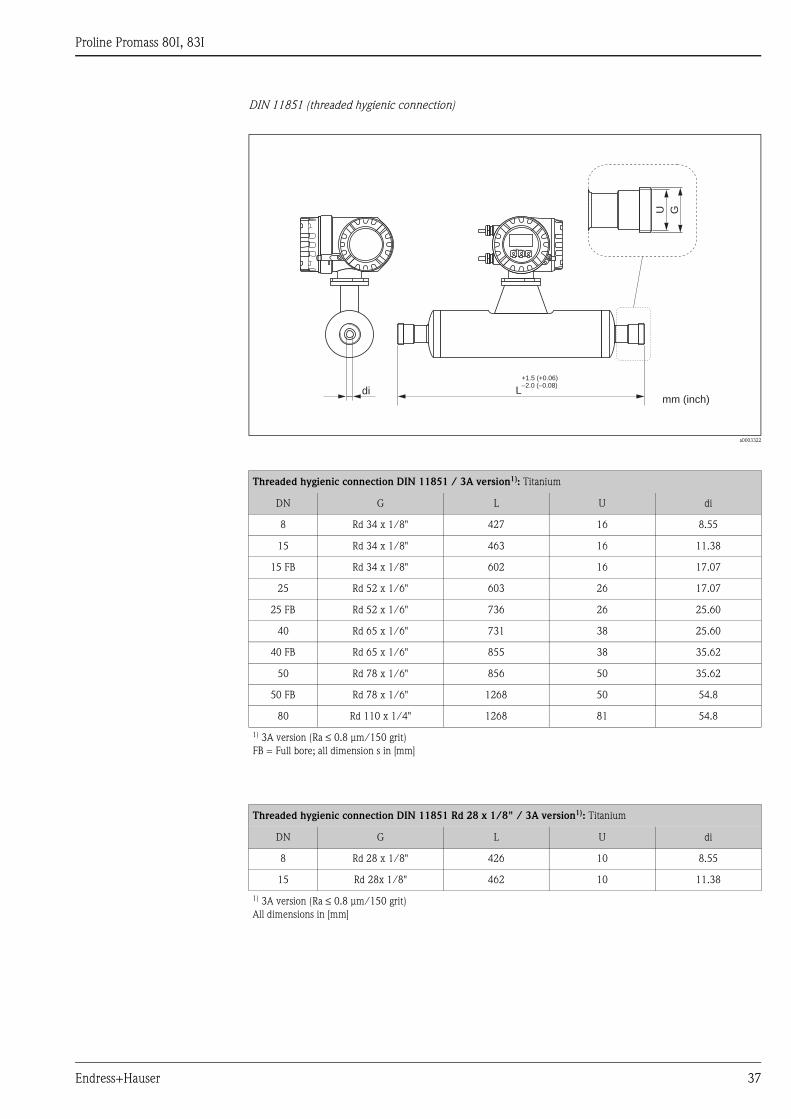
DIN 11851 (threaded hygienic connection) → ä 37
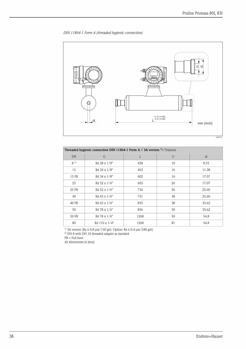
DIN 11864-1 Form A (threaded hygienic connection) → ä 38
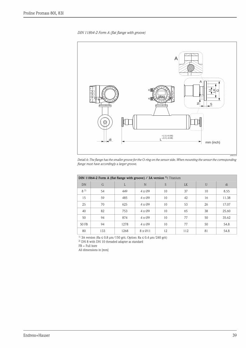
DIN 11864-2 Form A (flat flange with groove) → ä 39
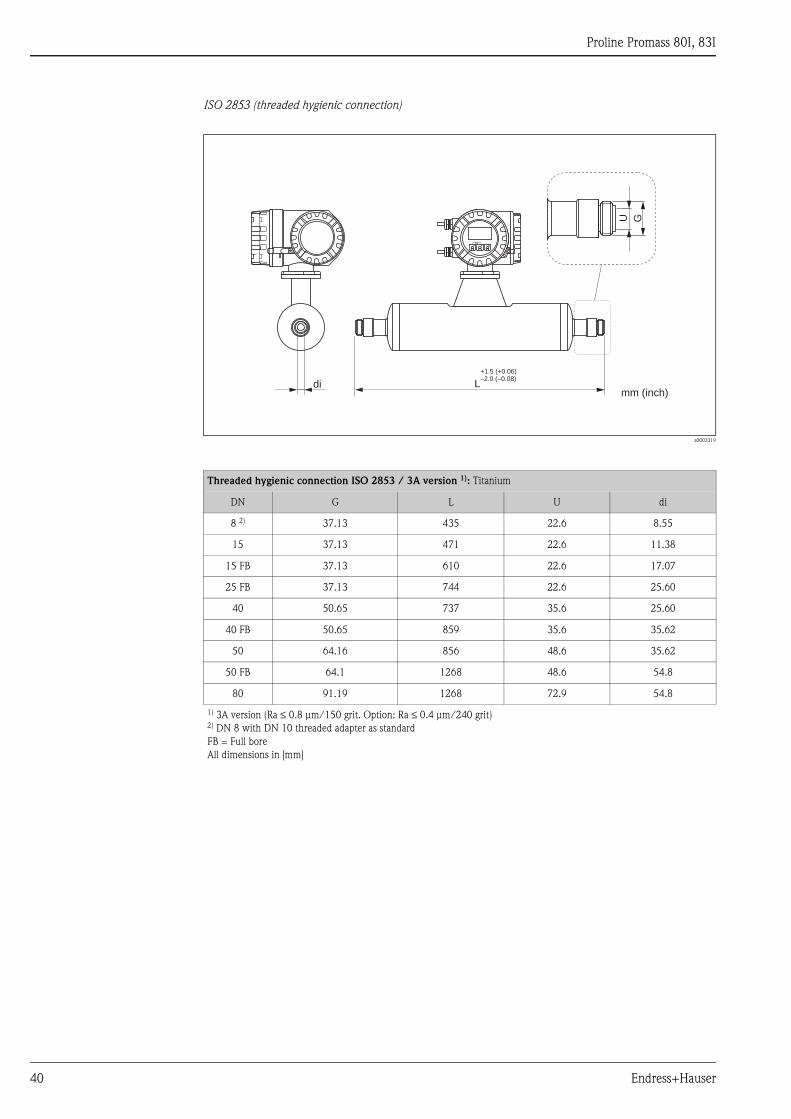
ISO 2853 (threaded hygienic connection) → ä 40
SMS 1145 (threaded hygienic connection) → ä 41
Process connections in US units
Flange connections ASME B16.5 → ä 42
Tri-Clamp → ä 44
Eccentric Tri-Clamp → ä 45
SMS 1145 (threaded hygienic connection) → ä 46
Purge connections / secondary containment monitoring → ä 47
Proline Promass 80I, 83I
Endress+Hauser 25
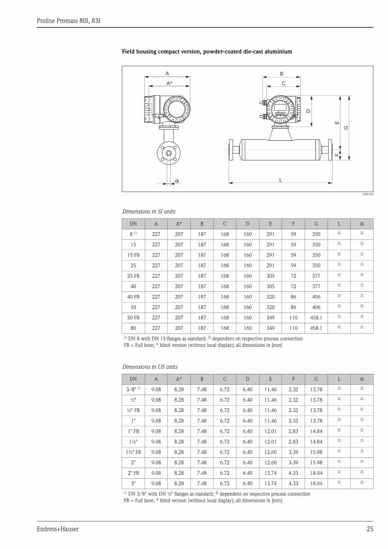
Field housing compact version, powder-coated die-cast aluminium
A0006964
Dimensions in SI units
Dimensions in US units
DN A A* B C D E F G L di
8 1) 227 207 187 168 160 291 59 350 2) 2)
15 227 207 187 168 160 291 59 350 2) 2)
15 FB 227 207 187 168 160 291 59 350 2) 2)
25 227 207 187 168 160 291 59 350 2) 2)
25 FB 227 207 187 168 160 305 72 377 2) 2)
40 227 207 187 168 160 305 72 377 2) 2)
40 FB 227 207 187 168 160 320 86 406 2) 2)
50 227 207 187 168 160 320 86 406 2) 2)
50 FB 227 207 187 168 160 349 110 458.1 2) 2)
80 227 207 187 168 160 349 110 458.1 2) 2)
1) DN 8 with DN 15 flanges as standard; 2) dependent on respective process connection
FB = Full bore; * blind version (without local display); all dimensions in [mm]
DN A A* B C D E F G L di
3/8" 1) 9.08 8.28 7.48 6.72 6.40 11.46 2.32 13.78 2) 2)
½" 9.08 8.28 7.48 6.72 6.40 11.46 2.32 13.78 2) 2)
½" FB 9.08 8.28 7.48 6.72 6.40 11.46 2.32 13.78 2) 2)
1" 9.08 8.28 7.48 6.72 6.40 11.46 2.32 13.78 2) 2)
1" FB 9.08 8.28 7.48 6.72 6.40 12.01 2.83 14.84 2) 2)
1½" 9.08 8.28 7.48 6.72 6.40 12.01 2.83 14.84 2) 2)
1½" FB 9.08 8.28 7.48 6.72 6.40 12.60 3.39 15.98 2) 2)
2" 9.08 8.28 7.48 6.72 6.40 12.60 3.39 15.98 2) 2)
2" FB 9.08 8.28 7.48 6.72 6.40 13.74 4.33 18.04 2) 2)
3" 9.08 8.28 7.48 6.72 6.40 13.74 4.33 18.04 2) 2)
1) DN 3/8" with DN ½" flanges as standard; 2) dependent on respective process connection
FB = Full bore; * blind version (without local display); all dimensions in [mm]
Esc
E
- +
A
A*
B
C
E
D
G
F
L
G
di
Proline Promass 80I, 83I
26 Endress+Hauser
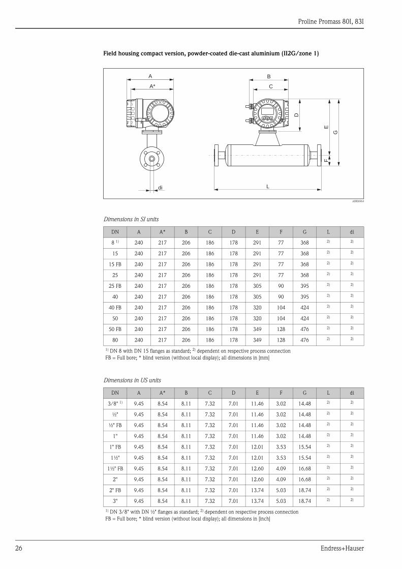
Field housing compact version, powder-coated die-cast aluminium (II2G/zone 1)
A0006964
Dimensions in SI units
Dimensions in US units
DN A A* B C D E F G L di
8 1) 240 217 206 186 178 291 77 368 2) 2)
15 240 217 206 186 178 291 77 368 2) 2)
15 FB 240 217 206 186 178 291 77 368 2) 2)
25 240 217 206 186 178 291 77 368 2) 2)
25 FB 240 217 206 186 178 305 90 395 2) 2)
40 240 217 206 186 178 305 90 395 2) 2)
40 FB 240 217 206 186 178 320 104 424 2) 2)
50 240 217 206 186 178 320 104 424 2) 2)
50 FB 240 217 206 186 178 349 128 476 2) 2)
80 240 217 206 186 178 349 128 476 2) 2)
1) DN 8 with DN 15 flanges as standard; 2) dependent on respective process connection
FB = Full bore; * blind version (without local display); all dimensions in [mm]
DN A A* B C D E F G L di
3/8" 1) 9.45 8.54 8.11 7.32 7.01 11.46 3.02 14.48 2) 2)
½" 9.45 8.54 8.11 7.32 7.01 11.46 3.02 14.48 2) 2)
½" FB 9.45 8.54 8.11 7.32 7.01 11.46 3.02 14.48 2) 2)
1" 9.45 8.54 8.11 7.32 7.01 11.46 3.02 14.48 2) 2)
1" FB 9.45 8.54 8.11 7.32 7.01 12.01 3.53 15.54 2) 2)
1½" 9.45 8.54 8.11 7.32 7.01 12.01 3.53 15.54 2) 2)
1½" FB 9.45 8.54 8.11 7.32 7.01 12.60 4.09 16.68 2) 2)
2" 9.45 8.54 8.11 7.32 7.01 12.60 4.09 16.68 2) 2)
2" FB 9.45 8.54 8.11 7.32 7.01 13.74 5.03 18.74 2) 2)
3" 9.45 8.54 8.11 7.32 7.01 13.74 5.03 18.74 2) 2)
1) DN 3/8" with DN ½" flanges as standard; 2) dependent on respective process connection
FB = Full bore; * blind version (without local display); all dimensions in [inch]
Esc
E
- +
A
A*
B
C
E
D
G
F
L
G
di
Proline Promass 80I, 83I
Endress+Hauser 27
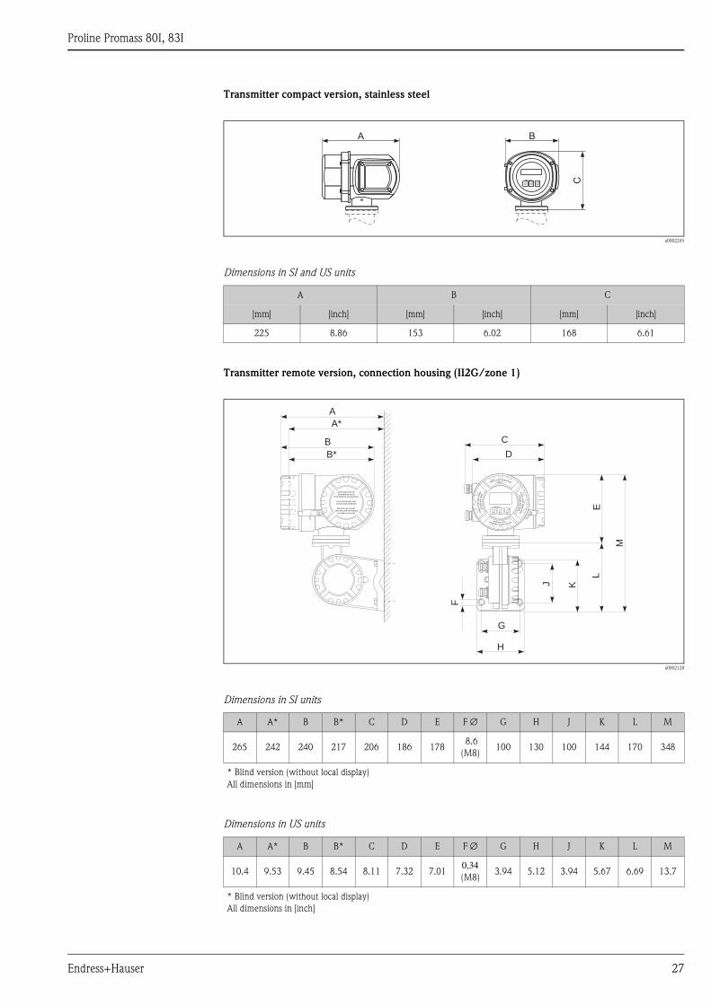
Transmitter compact version, stainless steel
a0002245
Dimensions in SI and US units
Transmitter remote version, connection housing (II2G/zone 1)
a0002128
Dimensions in SI units
Dimensions in US units
A B C
[mm] [inch] [mm] [inch] [mm] [inch]
225 8.86 153 6.02 168 6.61
A A* B B* C D E F ∅ G H J K L M
265 242 240 217 206 186 178 8.6
(M8)100 130 100 144 170 348
* Blind version (without local display)
All dimensions in [mm]
A A* B B* C D E F ∅ G H J K L M
10.4 9.53 9.45 8.54 8.11 7.32 7.010,34
(M8)3.94 5.12 3.94 5.67 6.69 13.7
* Blind version (without local display)
All dimensions in [inch]
A B
CEsc
E- +
Nicht unter Spannungöffnen
Keep
cover
tightw
hile
circuit s
are
alive
Nepasouvrirl’appareil soustension
Keep
cove
rtightw
hile
circ
uits
are
aliv
e
Nicht-eigensichereStromkreise durch
IP40-Abdeckung geschützt
Non-intrinsically safecircuits Ip40 protected
Boucles de courantsans sécurité intrinsèque
protégées par Ip40
B*
B
A*
A
F
G
D
C
H
J K
L
M
EEsc
E+–
Proline Promass 80I, 83I
28 Endress+Hauser
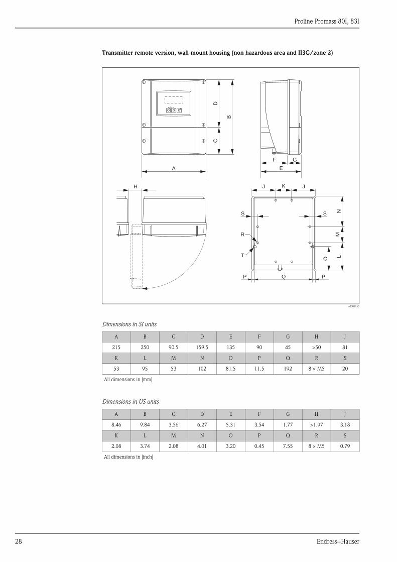
Transmitter remote version, wall-mount housing (non hazardous area and II3G/zone 2)
a0001150
Dimensions in SI units
Dimensions in US units
A B C D E F G H J
215 250 90.5 159.5 135 90 45 >50 81
K L M N O P Q R S
53 95 53 102 81.5 11.5 192 8 × M5 20
All dimensions in [mm]
A B C D E F G H J
8.46 9.84 3.56 6.27 5.31 3.54 1.77 >1.97 3.18
K L M N O P Q R S
2.08 3.74 2.08 4.01 3.20 0.45 7.55 8 × M5 0.79
All dimensions in [inch]
Esc
E- +
DC
B
A
F
E
G
KJ
Q
NL
O
R
H J
M
P P
SS
T
Proline Promass 80I, 83I
Endress+Hauser 29
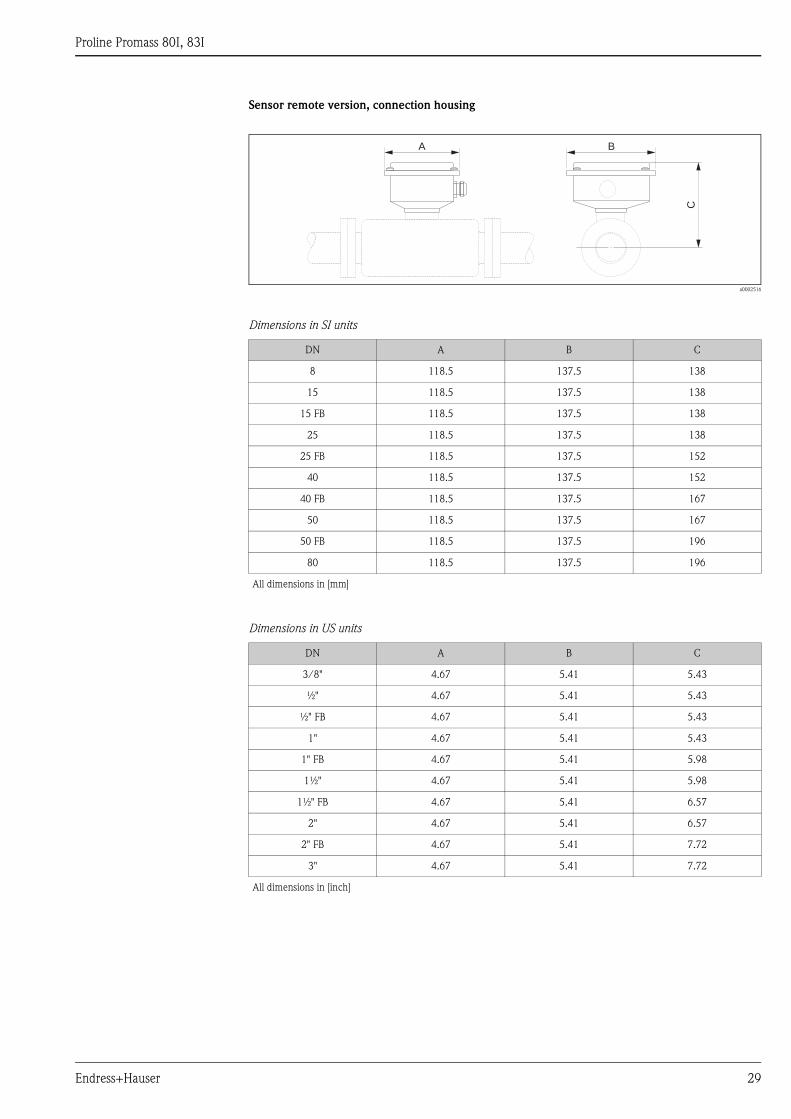
Sensor remote version, connection housing
a0002516
Dimensions in SI units
Dimensions in US units
DN A B C
8 118.5 137.5 138
15 118.5 137.5 138
15 FB 118.5 137.5 138
25 118.5 137.5 138
25 FB 118.5 137.5 152
40 118.5 137.5 152
40 FB 118.5 137.5 167
50 118.5 137.5 167
50 FB 118.5 137.5 196
80 118.5 137.5 196
All dimensions in [mm]
DN A B C
3/8" 4.67 5.41 5.43
½" 4.67 5.41 5.43
½" FB 4.67 5.41 5.43
1" 4.67 5.41 5.43
1" FB 4.67 5.41 5.98
1½" 4.67 5.41 5.98
1½" FB 4.67 5.41 6.57
2" 4.67 5.41 6.57
2" FB 4.67 5.41 7.72
3" 4.67 5.41 7.72
All dimensions in [inch]
B
C
A
Proline Promass 80I, 83I
30 Endress+Hauser
Process connections in SI units
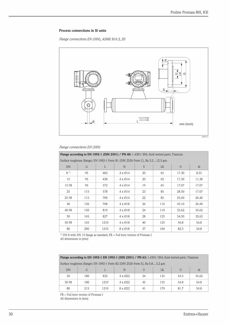
Flange connections EN (DIN), ASME B16.5, JIS
a0003313
Flange connections EN (DIN)
Flange according to EN 1092-1 (DIN 2501) / PN 40: 1.4301/304, fluid wetted parts: Titanium
Surface roughness (flange): EN 1092-1 Form B1 (DIN 2526 Form C), Ra 3.2…12.5 μm
DN G L N S LK U di
8 1) 95 402 4 x Ø14 20 65 17.30 8.55
15 95 438 4 x Ø14 20 65 17.30 11.38
15 FB 95 572 4 x Ø14 19 65 17.07 17.07
25 115 578 4 x Ø14 23 85 28.50 17.07
25 FB 115 700 4 x Ø14 22 85 25.60 26.40
40 150 708 4 x Ø18 26 110 43.10 26.40
40 FB 150 819 4 x Ø18 24 110 35.62 35.62
50 165 827 4 x Ø18 28 125 54.50 35.62
50 FB 165 1210 4 x Ø18 40 125 54.8 54.8
80 200 1210 8 x Ø18 37 160 82.5 54.8
1) DN 8 with DN 15 flange as standard; FB = Full bore version of Promass I
All dimensions in [mm]
Flange according to EN 1092-1 EN 1092-1 (DIN 2501) / PN 63: 1.4301/304, fluid wetted parts: Titanium
Surface roughness (flange): EN 1092-1 Form B2 (DIN 2526 Form E), Ra 0.8…3.2 μm
DN G L N S LK U di
50 180 832 4 x Ø22 34 135 54.5 35.62
50 FB 180 1210 4 x Ø22 45 135 54.8 54.8
80 215 1210 8 x Ø22 41 170 81.7 54.8
FB = Full bore version of Promass I
All dimensions in [mm]
Esc
E- +
L
G
di
S
GU
N
LK
+1.5 (+0.06)–2.0 (–0.08)
mm (inch)
Proline Promass 80I, 83I
Endress+Hauser 31
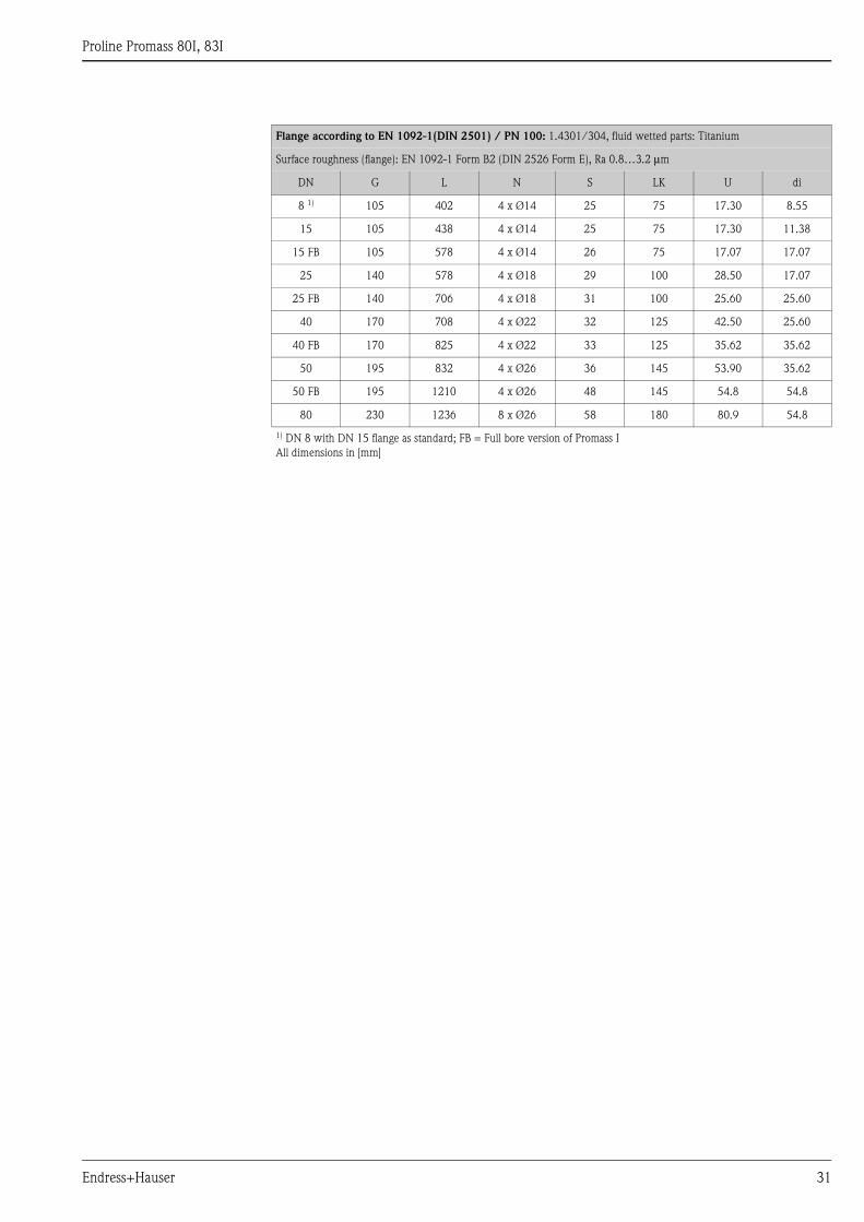
Flange according to EN 1092-1(DIN 2501) / PN 100: 1.4301/304, fluid wetted parts: Titanium
Surface roughness (flange): EN 1092-1 Form B2 (DIN 2526 Form E), Ra 0.8…3.2 μm
DN G L N S LK U di
8 1) 105 402 4 x Ø14 25 75 17.30 8.55
15 105 438 4 x Ø14 25 75 17.30 11.38
15 FB 105 578 4 x Ø14 26 75 17.07 17.07
25 140 578 4 x Ø18 29 100 28.50 17.07
25 FB 140 706 4 x Ø18 31 100 25.60 25.60
40 170 708 4 x Ø22 32 125 42.50 25.60
40 FB 170 825 4 x Ø22 33 125 35.62 35.62
50 195 832 4 x Ø26 36 145 53.90 35.62
50 FB 195 1210 4 x Ø26 48 145 54.8 54.8
80 230 1236 8 x Ø26 58 180 80.9 54.8
1) DN 8 with DN 15 flange as standard; FB = Full bore version of Promass I
All dimensions in [mm]
Proline Promass 80I, 83I
32 Endress+Hauser
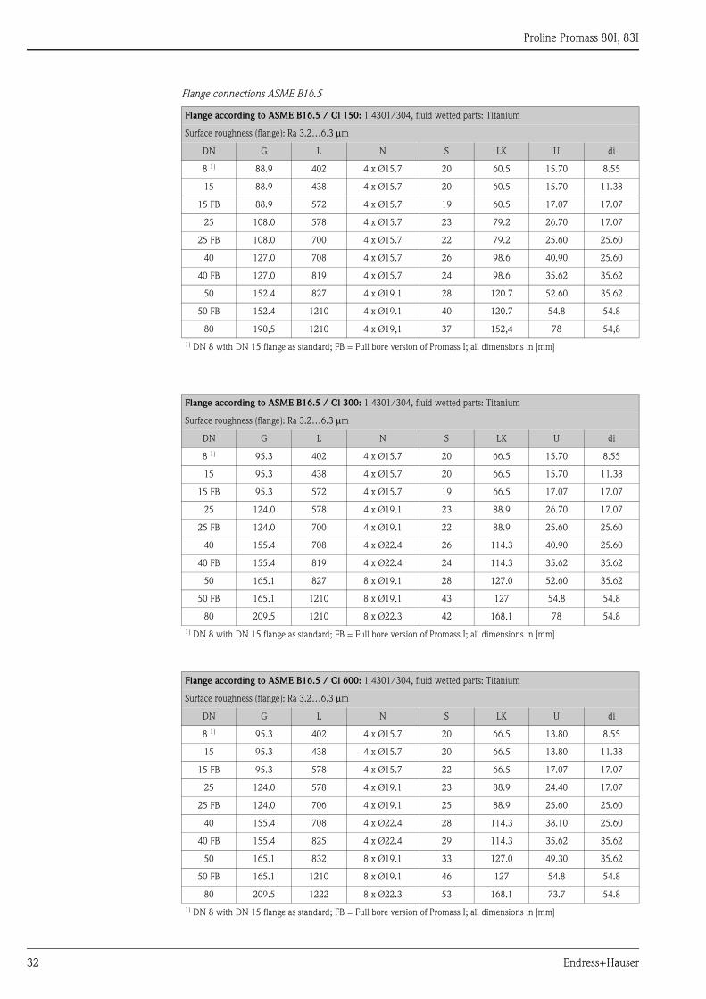
Flange connections ASME B16.5
Flange according to ASME B16.5 / Cl 150: 1.4301/304, fluid wetted parts: Titanium
Surface roughness (flange): Ra 3.2…6.3 μm
DN G L N S LK U di
8 1) 88.9 402 4 x Ø15.7 20 60.5 15.70 8.55
15 88.9 438 4 x Ø15.7 20 60.5 15.70 11.38
15 FB 88.9 572 4 x Ø15.7 19 60.5 17.07 17.07
25 108.0 578 4 x Ø15.7 23 79.2 26.70 17.07
25 FB 108.0 700 4 x Ø15.7 22 79.2 25.60 25.60
40 127.0 708 4 x Ø15.7 26 98.6 40.90 25.60
40 FB 127.0 819 4 x Ø15.7 24 98.6 35.62 35.62
50 152.4 827 4 x Ø19.1 28 120.7 52.60 35.62
50 FB 152.4 1210 4 x Ø19.1 40 120.7 54.8 54.8
80 190,5 1210 4 x Ø19,1 37 152,4 78 54,8
1) DN 8 with DN 15 flange as standard; FB = Full bore version of Promass I; all dimensions in [mm]
Flange according to ASME B16.5 / Cl 300: 1.4301/304, fluid wetted parts: Titanium
Surface roughness (flange): Ra 3.2…6.3 μm
DN G L N S LK U di
8 1) 95.3 402 4 x Ø15.7 20 66.5 15.70 8.55
15 95.3 438 4 x Ø15.7 20 66.5 15.70 11.38
15 FB 95.3 572 4 x Ø15.7 19 66.5 17.07 17.07
25 124.0 578 4 x Ø19.1 23 88.9 26.70 17.07
25 FB 124.0 700 4 x Ø19.1 22 88.9 25.60 25.60
40 155.4 708 4 x Ø22.4 26 114.3 40.90 25.60
40 FB 155.4 819 4 x Ø22.4 24 114.3 35.62 35.62
50 165.1 827 8 x Ø19.1 28 127.0 52.60 35.62
50 FB 165.1 1210 8 x Ø19.1 43 127 54.8 54.8
80 209.5 1210 8 x Ø22.3 42 168.1 78 54.8
1) DN 8 with DN 15 flange as standard; FB = Full bore version of Promass I; all dimensions in [mm]
Flange according to ASME B16.5 / Cl 600: 1.4301/304, fluid wetted parts: Titanium
Surface roughness (flange): Ra 3.2…6.3 μm
DN G L N S LK U di
8 1) 95.3 402 4 x Ø15.7 20 66.5 13.80 8.55
15 95.3 438 4 x Ø15.7 20 66.5 13.80 11.38
15 FB 95.3 578 4 x Ø15.7 22 66.5 17.07 17.07
25 124.0 578 4 x Ø19.1 23 88.9 24.40 17.07
25 FB 124.0 706 4 x Ø19.1 25 88.9 25.60 25.60
40 155.4 708 4 x Ø22.4 28 114.3 38.10 25.60
40 FB 155.4 825 4 x Ø22.4 29 114.3 35.62 35.62
50 165.1 832 8 x Ø19.1 33 127.0 49.30 35.62
50 FB 165.1 1210 8 x Ø19.1 46 127 54.8 54.8
80 209.5 1222 8 x Ø22.3 53 168.1 73.7 54.8
1) DN 8 with DN 15 flange as standard; FB = Full bore version of Promass I; all dimensions in [mm]
Proline Promass 80I, 83I
Endress+Hauser 33
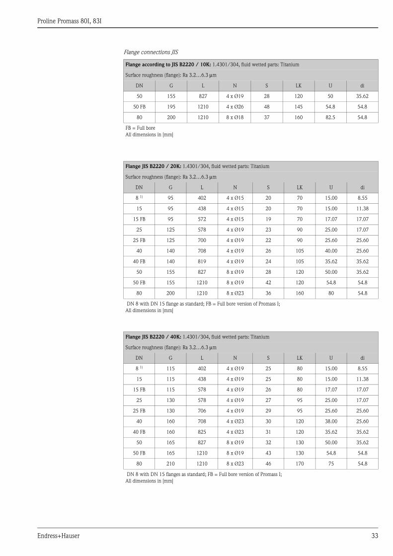
Flange connections JIS
Flange according to JIS B2220 / 10K: 1.4301/304, fluid wetted parts: Titanium
Surface roughness (flange): Ra 3.2…6.3 μm
DN G L N S LK U di
50 155 827 4 x Ø19 28 120 50 35.62
50 FB 195 1210 4 x Ø26 48 145 54.8 54.8
80 200 1210 8 x Ø18 37 160 82.5 54.8
FB = Full bore
All dimensions in [mm]
Flange JIS B2220 / 20K: 1.4301/304, fluid wetted parts: Titanium
Surface roughness (flange): Ra 3.2…6.3 μm
DN G L N S LK U di
8 1) 95 402 4 x Ø15 20 70 15.00 8.55
15 95 438 4 x Ø15 20 70 15.00 11.38
15 FB 95 572 4 x Ø15 19 70 17.07 17.07
25 125 578 4 x Ø19 23 90 25.00 17.07
25 FB 125 700 4 x Ø19 22 90 25.60 25.60
40 140 708 4 x Ø19 26 105 40.00 25.60
40 FB 140 819 4 x Ø19 24 105 35.62 35.62
50 155 827 8 x Ø19 28 120 50.00 35.62
50 FB 155 1210 8 x Ø19 42 120 54.8 54.8
80 200 1210 8 x Ø23 36 160 80 54.8
DN 8 with DN 15 flange as standard; FB = Full bore version of Promass I;
All dimensions in [mm]
Flange JIS B2220 / 40K: 1.4301/304, fluid wetted parts: Titanium
Surface roughness (flange): Ra 3.2…6.3 μm
DN G L N S LK U di
8 1) 115 402 4 x Ø19 25 80 15.00 8.55
15 115 438 4 x Ø19 25 80 15.00 11.38
15 FB 115 578 4 x Ø19 26 80 17.07 17.07
25 130 578 4 x Ø19 27 95 25.00 17.07
25 FB 130 706 4 x Ø19 29 95 25.60 25.60
40 160 708 4 x Ø23 30 120 38.00 25.60
40 FB 160 825 4 x Ø23 31 120 35.62 35.62
50 165 827 8 x Ø19 32 130 50.00 35.62
50 FB 165 1210 8 x Ø19 43 130 54.8 54.8
80 210 1210 8 x Ø23 46 170 75 54.8
DN 8 with DN 15 flanges as standard; FB = Full bore version of Promass I;
All dimensions in [mm]
Proline Promass 80I, 83I
34 Endress+Hauser
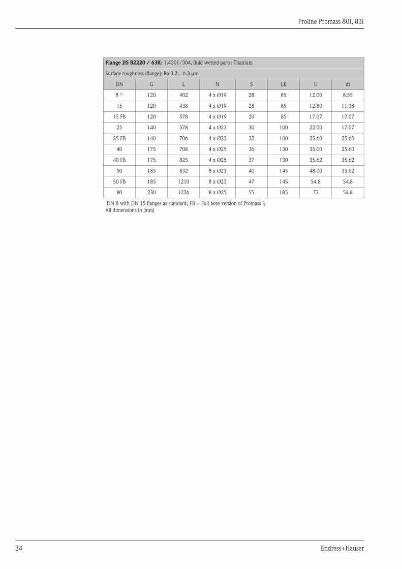
Flange JIS B2220 / 63K: 1.4301/304, fluid wetted parts: Titanium
Surface roughness (flange): Ra 3.2…6.3 μm
DN G L N S LK U di
8 1) 120 402 4 x Ø19 28 85 12.00 8.55
15 120 438 4 x Ø19 28 85 12.80 11.38
15 FB 120 578 4 x Ø19 29 85 17.07 17.07
25 140 578 4 x Ø23 30 100 22.00 17.07
25 FB 140 706 4 x Ø23 32 100 25.60 25.60
40 175 708 4 x Ø25 36 130 35.00 25.60
40 FB 175 825 4 x Ø25 37 130 35.62 35.62
50 185 832 8 x Ø23 40 145 48.00 35.62
50 FB 185 1210 8 x Ø23 47 145 54.8 54.8
80 230 1226 8 x Ø25 55 185 73 54.8
DN 8 with DN 15 flanges as standard; FB = Full bore version of Promass I;
All dimensions in [mm]
Proline Promass 80I, 83I
Endress+Hauser 35
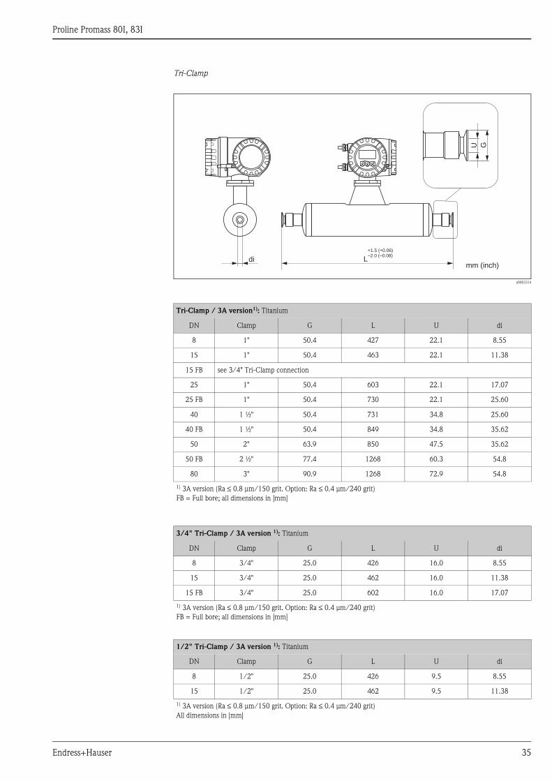
Tri-Clamp
a0003314
Tri-Clamp / 3A version1): Titanium
DN Clamp G L U di
8 1" 50.4 427 22.1 8.55
15 1" 50.4 463 22.1 11.38
15 FB see 3/4" Tri-Clamp connection
25 1" 50.4 603 22.1 17.07
25 FB 1" 50.4 730 22.1 25.60
40 1 ½" 50.4 731 34.8 25.60
40 FB 1 ½" 50.4 849 34.8 35.62
50 2" 63.9 850 47.5 35.62
50 FB 2 ½" 77.4 1268 60.3 54.8
80 3" 90.9 1268 72.9 54.8
1) 3A version (Ra ≤ 0.8 μm/150 grit. Option: Ra ≤ 0.4 μm/240 grit)
FB = Full bore; all dimensions in [mm]
3/4" Tri-Clamp / 3A version 1): Titanium
DN Clamp G L U di
8 3/4" 25.0 426 16.0 8.55
15 3/4" 25.0 462 16.0 11.38
15 FB 3/4" 25.0 602 16.0 17.07
1) 3A version (Ra ≤ 0.8 μm/150 grit. Option: Ra ≤ 0.4 μm/240 grit)
FB = Full bore; all dimensions in [mm]
1/2" Tri-Clamp / 3A version 1): Titanium
DN Clamp G L U di
8 1/2" 25.0 426 9.5 8.55
15 1/2" 25.0 462 9.5 11.38
1) 3A version (Ra ≤ 0.8 μm/150 grit. Option: Ra ≤ 0.4 μm/240 grit)
All dimensions in [mm]
Esc
E- +
Ldi
GU
+1.5 (+0.06)–2.0 (–0.08)
mm (inch)

Proline Promass 80I, 83I
36 Endress+Hauser
Eccentric Tri-Clamp
a0010012
! Note!
Further information refer to "Eccentric Tri-clamps" → ä 19
Eccentric Tri-Clamps: Titanium
DN Clamp G L U di
8 ½" 25.0 427 9.5 8.5
15 3/4" 25.0 463 15.75 11.3
15 FB 1" 50.4 603 22.1 17
25 1" 50.4 603 22.1 17
25 FB 1½" 50.4 730 34.8 26.4
40 1½" 50.4 730 34.8 26.4
40 FB 2" 63.9 849 47.5 35.6
50 2" 63.9 849 47.5 35.6
50 FB 2 ½" 77.4 1268 60.3 54.8
50 FB 3" 82.572 1268 72.9 54.8
80 2 ½" 77.4 1268 60.3 54.8
80 3" 82.572 1268 72.9 54.8
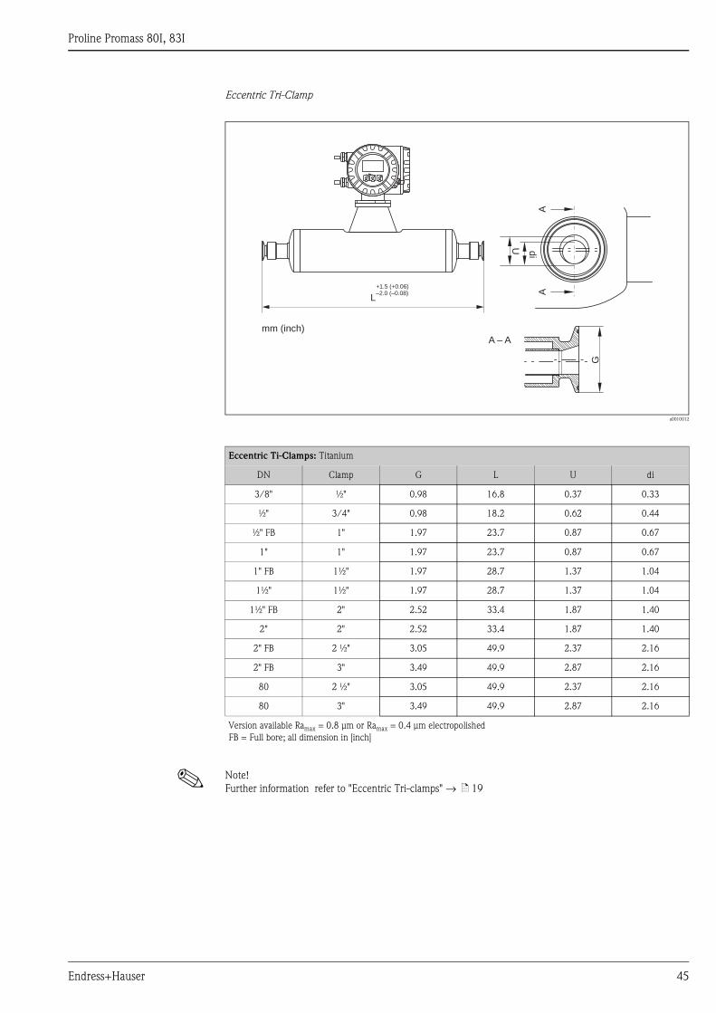
Version available Ramax = 0.8 μm or Ramax = 0.4 μm electropolished
FB = Full bore; all dimension in [mm]
di
U
G
A
A – A
A
Esc
E- +
mm (inch)
L
+1.5 (+0.06)–2.0 (–0.08)
Proline Promass 80I, 83I
Endress+Hauser 37
DIN 11851 (threaded hygienic connection)
a0003322
Threaded hygienic connection DIN 11851 / 3A version1): Titanium
DN G L U di
8 Rd 34 x 1/8" 427 16 8.55
15 Rd 34 x 1/8" 463 16 11.38
15 FB Rd 34 x 1/8" 602 16 17.07
25 Rd 52 x 1/6" 603 26 17.07
25 FB Rd 52 x 1/6" 736 26 25.60
40 Rd 65 x 1/6" 731 38 25.60
40 FB Rd 65 x 1/6" 855 38 35.62
50 Rd 78 x 1/6" 856 50 35.62
50 FB Rd 78 x 1/6" 1268 50 54.8
80 Rd 110 x 1/4" 1268 81 54.8
1) 3A version (Ra ≤ 0.8 μm/150 grit)
FB = Full bore; all dimension s in [mm]
Threaded hygienic connection DIN 11851 Rd 28 x 1/8" / 3A version1): Titanium
DN G L U di
8 Rd 28 x 1/8" 426 10 8.55
15 Rd 28x 1/8" 462 10 11.38
1) 3A version (Ra ≤ 0.8 μm/150 grit)
All dimensions in [mm]
Esc
E- +
Ldi
+1.5 (+0.06)–2.0 (–0.08)
GU
mm (inch)
Proline Promass 80I, 83I
38 Endress+Hauser
DIN 11864-1 Form A (threaded hygienic connection)
a0003317
Threaded hygienic connection DIN 11864-1 Form A / 3A version 1): Titanium
DN G L U di
8 1) Rd 28 x 1/8" 428 10 8.55
15 Rd 34 x 1/8" 463 16 11.38
15 FB Rd 34 x 1/8" 602 16 17.07
25 Rd 52 x 1/6" 603 26 17.07
25 FB Rd 52 x 1/6" 734 26 25.60
40 Rd 65 x 1/6" 731 38 25.60
40 FB Rd 65 x 1/6" 855 38 35.62
50 Rd 78 x 1/6" 856 50 35.62
50 FB Rd 78 x 1/6" 1268 50 54.8
80 Rd 110 x 1/4" 1268 81 54.8
1) 3A version (Ra ≤ 0.8 μm/150 grit. Option: Ra ≤ 0.4 μm/240 grit)2) DN 8 with DN 10 threaded adapter as standard
FB = Full bore
All dimensions in [mm]
Esc
E- +
Ldi
+1.5 (+0.06)–2.0 (–0.08)
GU
mm (inch)
Proline Promass 80I, 83I
Endress+Hauser 39
DIN 11864-2 Form A (flat flange with groove)
a0003318
Detail A: The flange has the smaller groove for the O-ring on the sensor side. When mounting the sensor the corresponding
flange must have accordingly a larger groove.
Esc
E- +
L
+1.5 (+0.06)–2.0 (–0.08)
di
G
N S
LKU
mm (inch)
A
A
DIN 11864-2 Form A (flat flange with groove) / 3A version 1): Titanium
DN G L N S LK U di
8 2) 54 449 4 x Ø9 10 37 10 8.55
15 59 485 4 x Ø9 10 42 16 11.38
25 70 625 4 x Ø9 10 53 26 17.07
40 82 753 4 x Ø9 10 65 38 25.60
50 94 874 4 x Ø9 10 77 50 35.62
50 FB 94 1278 4 x Ø9 10 77 50 54.8
80 133 1268 8 x Ø11 12 112 81 54.8
1) 3A version (Ra ≤ 0.8 μm/150 grit. Option: Ra ≤ 0.4 μm/240 grit)2) DN 8 with DN 10 threaded adapter as standard
FB = Full bore
All dimensions in [mm]
Proline Promass 80I, 83I
40 Endress+Hauser
ISO 2853 (threaded hygienic connection)
a0003319
Threaded hygienic connection ISO 2853 / 3A version 1): Titanium
DN G L U di
8 2) 37.13 435 22.6 8.55
15 37.13 471 22.6 11.38
15 FB 37.13 610 22.6 17.07
25 FB 37.13 744 22.6 25.60
40 50.65 737 35.6 25.60
40 FB 50.65 859 35.6 35.62
50 64.16 856 48.6 35.62
50 FB 64.1 1268 48.6 54.8
80 91.19 1268 72.9 54.8
1) 3A version (Ra ≤ 0.8 μm/150 grit. Option: Ra ≤ 0.4 μm/240 grit)2) DN 8 with DN 10 threaded adapter as standard
FB = Full bore
All dimensions in [mm]
Esc
E- +
Ldi
+1.5 (+0.06)–2.0 (–0.08)
GU
mm (inch)
Proline Promass 80I, 83I
Endress+Hauser 41
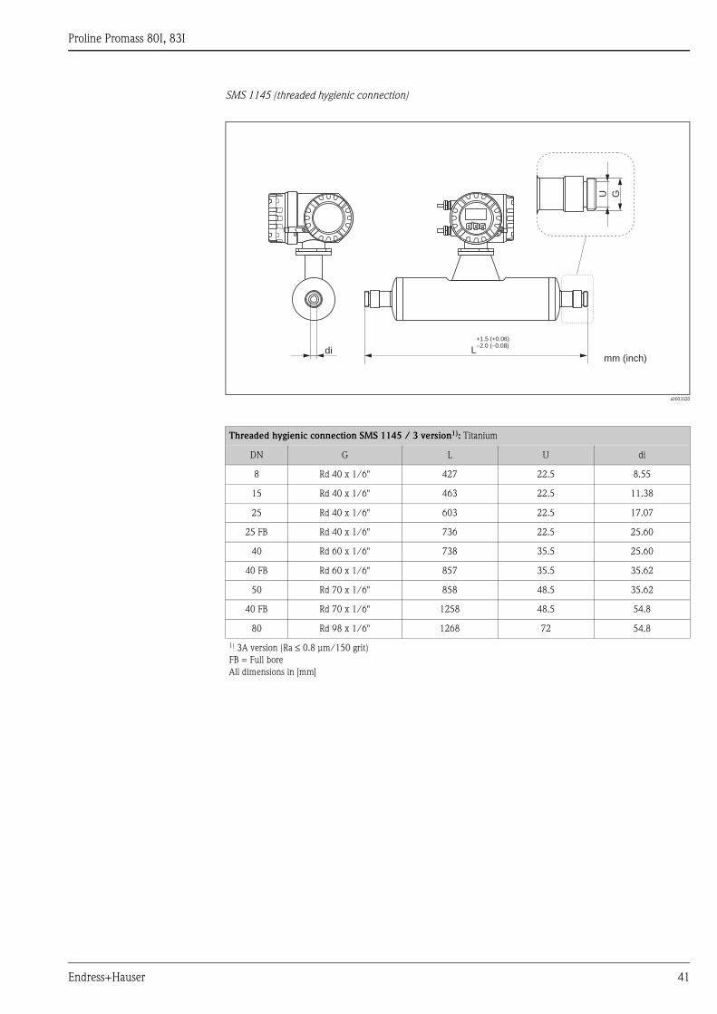
SMS 1145 (threaded hygienic connection)
a0003320
Threaded hygienic connection SMS 1145 / 3 version1): Titanium
DN G L U di
8 Rd 40 x 1/6" 427 22.5 8.55
15 Rd 40 x 1/6" 463 22.5 11.38
25 Rd 40 x 1/6" 603 22.5 17.07
25 FB Rd 40 x 1/6" 736 22.5 25.60
40 Rd 60 x 1/6" 738 35.5 25.60
40 FB Rd 60 x 1/6" 857 35.5 35.62
50 Rd 70 x 1/6" 858 48.5 35.62
40 FB Rd 70 x 1/6" 1258 48.5 54.8
80 Rd 98 x 1/6" 1268 72 54.8
1) 3A version (Ra ≤ 0.8 μm/150 grit)
FB = Full bore
All dimensions in [mm]
Esc
E- +
Ldi
GU
+1.5 (+0.06)–2.0 (–0.08)
mm (inch)
Proline Promass 80I, 83I
42 Endress+Hauser
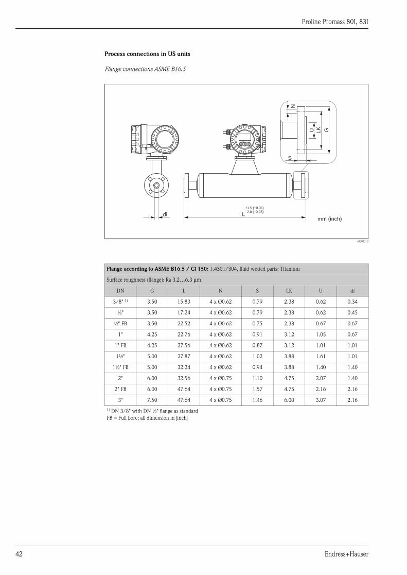
Process connections in US units
Flange connections ASME B16.5
a0003313
Flange according to ASME B16.5 / Cl 150: 1.4301/304, fluid wetted parts: Titanium
Surface roughness (flange): Ra 3.2…6.3 μm
DN G L N S LK U di
3/8" 1) 3.50 15.83 4 x Ø0.62 0.79 2.38 0.62 0.34
½" 3.50 17.24 4 x Ø0.62 0.79 2.38 0.62 0.45
½" FB 3.50 22.52 4 x Ø0.62 0.75 2.38 0.67 0.67
1" 4.25 22.76 4 x Ø0.62 0.91 3.12 1.05 0.67
1" FB 4.25 27.56 4 x Ø0.62 0.87 3.12 1.01 1.01
1½" 5.00 27.87 4 x Ø0.62 1.02 3.88 1.61 1.01
1½" FB 5.00 32.24 4 x Ø0.62 0.94 3.88 1.40 1.40
2" 6.00 32.56 4 x Ø0.75 1.10 4.75 2.07 1.40
2" FB 6.00 47.64 4 x Ø0.75 1.57 4.75 2.16 2.16
3" 7.50 47.64 4 x Ø0.75 1.46 6.00 3.07 2.16
1) DN 3/8" with DN ½" flange as standard
FB = Full bore; all dimension in [inch]
Esc
E- +
L
G
di
S
GU
N
LK
+1.5 (+0.06)–2.0 (–0.08)
mm (inch)
Proline Promass 80I, 83I
Endress+Hauser 43
Flange according to ASME B16.5 / Cl 300: 1.4301/304, fluid wetted parts: Titanium
Surface roughness (flange): Ra 3.2…6.3 μm
DN G L N S LK U di
3/8" 1) 3.75 15.83 4 x Ø0.62 0.79 2.62 0.62 0.34
½" 3.75 17.24 4 x Ø0.62 0.79 2.62 0.62 0.45
½" FB 3.75 22.52 4 x Ø0.62 0.75 2.62 0.67 0.67
1" 4.88 22.76 4 x Ø0.75 0.91 3.50 1.05 0.67
1" FB 4.88 27.56 4 x Ø0.75 0.87 3.50 1.01 1.01
1½" 6.12 27.87 4 x Ø0.88 1.02 4.50 1.61 1.01
1½" FB 6.12 32.24 4 x Ø0.88 0.94 4.50 1.40 1.40
2" 6.50 32.56 8 x Ø0.75 1.10 5.00 2.07 1.40
2" FB 6.50 47.64 8 x Ø0.75 1.69 5.00 2.16 2.16
3" 8.25 47.64 8 x Ø0.88 1.65 6.62 3.07 2.16
1) DN 3/8" with DN ½" flange as standard
FB = Full bore version of Promass I; all dimensions in [inch]
Flange according to ASME B16.5 / Cl 600: 1.4301/304, fluid wetted parts: Titanium
Surface roughness (flange): Ra 3.2…6.3 μm
DN G L N S LK U di
3/8" 1) 3.75 15.83 4 x Ø15.7 0.79 2.62 0.54 0.34
½" 3.75 17.24 4 x Ø15.7 0.79 2.62 0.54 0.45
½" FB 3.75 22.76 4 x Ø15.7 0.87 2.62 0.67 0.67
1" 4.88 22.76 4 x Ø19.1 0.91 3.50 0.96 0.67
1" FB 4.88 27.80 4 x Ø19.1 0.98 3.50 1.01 1.01
1½" 6.12 27.87 4 x Ø22.4 1.10 4.50 1.50 1.01
1½" FB 6.12 32.48 4 x Ø22.4 1.14 4.50 1.40 1.40
2" 6.50 32.76 8 x Ø19.1 1.30 5.00 1.94 1.40
2" FB 6.50 47.64 8 x Ø19.1 1.81 5.00 2.16 2.16
3" 8.25 48.11 8 x Ø22.3 2.09 6.62 2.90 2.16
1) DN 3/8" with DN ½" flange as standard
FB = Full bore version of Promass I; all dimensions in [inch]
Proline Promass 80I, 83I
44 Endress+Hauser
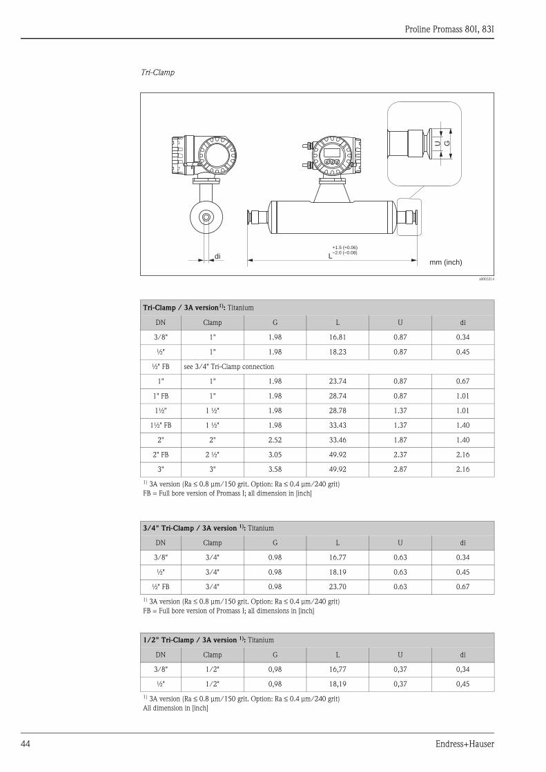
Tri-Clamp
a0003314
Tri-Clamp / 3A version1): Titanium
DN Clamp G L U di
3/8" 1" 1.98 16.81 0.87 0.34
½" 1" 1.98 18.23 0.87 0.45
½" FB see 3/4" Tri-Clamp connection
1" 1" 1.98 23.74 0.87 0.67
1" FB 1" 1.98 28.74 0.87 1.01
1½" 1 ½" 1.98 28.78 1.37 1.01
1½" FB 1 ½" 1.98 33.43 1.37 1.40
2" 2" 2.52 33.46 1.87 1.40
2" FB 2 ½" 3.05 49.92 2.37 2.16
3" 3" 3.58 49.92 2.87 2.16
1) 3A version (Ra ≤ 0.8 μm/150 grit. Option: Ra ≤ 0.4 μm/240 grit)
FB = Full bore version of Promass I; all dimension in [inch]
3/4" Tri-Clamp / 3A version 1): Titanium
DN Clamp G L U di
3/8" 3/4" 0.98 16.77 0.63 0.34
½" 3/4" 0.98 18.19 0.63 0.45
½" FB 3/4" 0.98 23.70 0.63 0.67
1) 3A version (Ra ≤ 0.8 μm/150 grit. Option: Ra ≤ 0.4 μm/240 grit)
FB = Full bore version of Promass I; all dimensions in [inch]
1/2" Tri-Clamp / 3A version 1): Titanium
DN Clamp G L U di
3/8" 1/2" 0,98 16,77 0,37 0,34
½" 1/2" 0,98 18,19 0,37 0,45
1) 3A version (Ra ≤ 0.8 μm/150 grit. Option: Ra ≤ 0.4 μm/240 grit)
All dimension in [inch]
Esc
E- +
Ldi
GU
+1.5 (+0.06)–2.0 (–0.08)
mm (inch)
Proline Promass 80I, 83I
Endress+Hauser 45
Eccentric Tri-Clamp
a0010012
! Note!
Further information refer to "Eccentric Tri-clamps" → ä 19
Eccentric Ti-Clamps: Titanium
DN Clamp G L U di
3/8" ½" 0.98 16.8 0.37 0.33
½" 3/4" 0.98 18.2 0.62 0.44
½" FB 1" 1.97 23.7 0.87 0.67
1" 1" 1.97 23.7 0.87 0.67
1" FB 1½" 1.97 28.7 1.37 1.04
1½" 1½" 1.97 28.7 1.37 1.04
1½" FB 2" 2.52 33.4 1.87 1.40
2" 2" 2.52 33.4 1.87 1.40
2" FB 2 ½" 3.05 49.9 2.37 2.16
2" FB 3" 3.49 49.9 2.87 2.16
80 2 ½" 3.05 49.9 2.37 2.16
80 3" 3.49 49.9 2.87 2.16
Version available Ramax = 0.8 μm or Ramax = 0.4 μm electropolished
FB = Full bore; all dimension in [inch]
di
U
G
A
A – A
A
Esc
E- +
mm (inch)
L
+1.5 (+0.06)–2.0 (–0.08)

Proline Promass 80I, 83I
46 Endress+Hauser
SMS 1145 (threaded hygienic connection)
a0003320
Threaded hygienic connection SMS 1145 / 3A version 1): Titanium
DN G L U di
3/8" Rd 40 x 1/6" 16.81 0.89 0.34
½" Rd 40 x 1/6" 18.23 0.89 0.45
½" FB Rd 40 x 1/6" 23.74 0.89 0.67
1" Rd 40 x 1/6" 28.98 0.89 1.01
1" FB Rd 60 x 1/6" 29.06 1.40 1.01
1½" Rd 60 x 1/6" 33.74 1.40 1.40
1½" FB Rd 70 x 1/6" 33.78 1.91 1.40
2" Rd 70 x 1/6" 49.53 1.91 2.16
2" FB Rd 98 x 1/6" 49.92 2.83 2.16
1) 3A version (Ra ≤ 0.8 μm/150 grit)
FB = Full bore
All dimension in [inch]
Esc
E- +
Ldi
GU
+1.5 (+0.06)–2.0 (–0.08)
mm (inch)
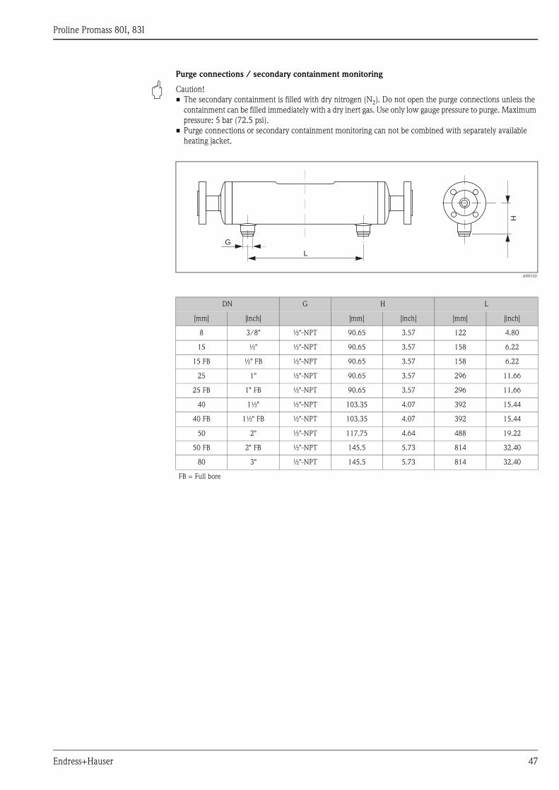
Proline Promass 80I, 83I
Endress+Hauser 47
Purge connections / secondary containment monitoring
" Caution!
• The secondary containment is filled with dry nitrogen (N2). Do not open the purge connections unless the
containment can be filled immediately with a dry inert gas. Use only low gauge pressure to purge. Maximum
pressure: 5 bar (72.5 psi).
• Purge connections or secondary containment monitoring can not be combined with separately available
heating jacket.
a0003321
DN G H L
[mm] [inch] [mm] [inch] [mm] [inch]
8 3/8" ½"-NPT 90.65 3.57 122 4.80
15 ½" ½"-NPT 90.65 3.57 158 6.22
15 FB ½" FB ½"-NPT 90.65 3.57 158 6.22
25 1" ½"-NPT 90.65 3.57 296 11.66
25 FB 1" FB ½"-NPT 90.65 3.57 296 11.66
40 1½" ½"-NPT 103.35 4.07 392 15.44
40 FB 1½" FB ½"-NPT 103.35 4.07 392 15.44
50 2" ½"-NPT 117.75 4.64 488 19.22
50 FB 2" FB ½"-NPT 145.5 5.73 814 32.40
80 3" ½"-NPT 145.5 5.73 814 32.40
FB = Full bore
G
L
H

Proline Promass 80I, 83I
48 Endress+Hauser
Weight • Compact version: see table below
• Remote version
– Sensor: see table below
– Wall-mount housing: 5 kg (11 lbs)
Weight in SI units
Weight in US units
Materials Transmitter housing
Compact version
• Powder coated die-cast aluminium
• Stainless steel housing: stainless steel 1.4301/ASTM 304
• Window material: Glass or polycarbonate
Remote version
• Remote field housing: powder coated die-cast aluminium
• Wall-mount housing: powder coated die-cast aluminium
• Window material: Glass
Sensor housing / containment
• Acid and alkali-resistant outer surface
• Stainless Steel 1.4301/1.4307/304L
Connection housing, sensor (remote version)
Stainless Steel 1.4301/304
Process connections
• Stainless Steel 1.4301/304
– Flanges according to EN 1092-1 (DIN 2501) / according to ASME B16.5 / JIS B2220
• Grade 2 titanium
– DIN 11864-2 Form A (flat flange with groove)
– Threaded hygienic connection
– DIN 11851
– SMS 1145
– ISO 2853
– DIN 11864-1 Form A
– Tri-Clamp (OD-Tubes)
Measuring tubes:
• Grade 9 titanium
• Grade 2 titanium (flange disk)
Seals:
Welded process connections without internal seals
DN [mm] 8 15 15 FB 25 25 FB 40 40 FB 50 50 FB 80
Compact version 13 15 21 22 41 42 67 69 120 124
Remote version 11 13 19 20 39 40 65 67 118 122
FB = Full bore; All values (weight) refer to devices with EN/DIN PN 40 flanges.
Weight information in [kg]
DN [inch] 3/8" ½" ½" FB 1" 1" FB 1½" 1½" FB 2" 2" FB 3"
Compact version 29 33 42 44 88 90 143 148 265 273
Remote version 24 29 37 40 84 86 139 143 260 269
FB = Full bore, All values (weight) refer to devices with EN/DIN PN 40 flanges.
Weight information in [lbs]
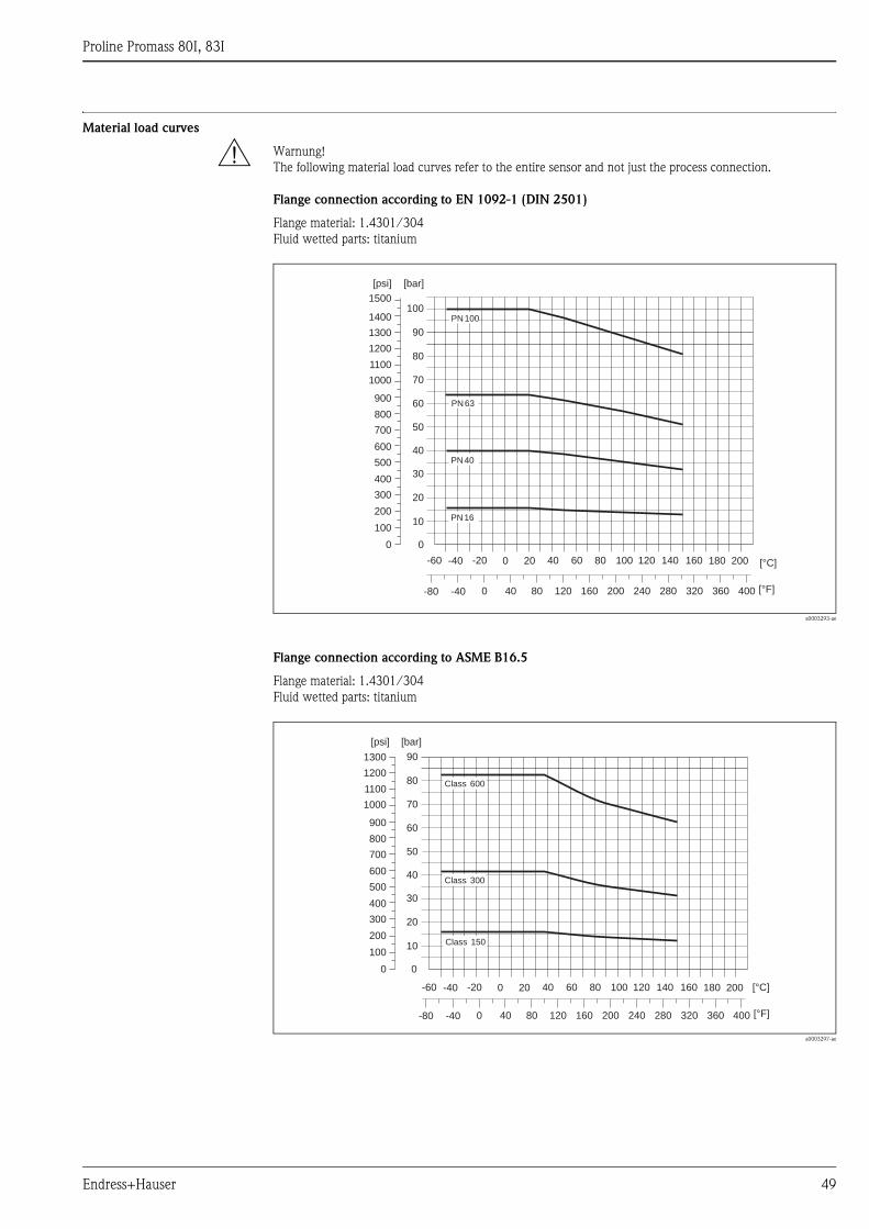
Proline Promass 80I, 83I
Endress+Hauser 49
Material load curves
# Warnung!
The following material load curves refer to the entire sensor and not just the process connection.
Flange connection according to EN 1092-1 (DIN 2501)
Flange material: 1.4301/304
Fluid wetted parts: titanium
a0003293-ae
Flange connection according to ASME B16.5
Flange material: 1.4301/304
Fluid wetted parts: titanium
a0003297-ae
0
10
20
30
40
50
70
60
80
90
100
[bar]
-60 -40 -20 0 20 40 60 80 100 120 140 180 200160 [°C]
PN 40
PN 16
PN 100
PN 63
[psi]
200
100
400
300
500
600
700
800
900
0
1000
1100
1200
1300
1400
1500
-40 0-80 40 80 120 160 200 240 280 320 360 400 [°F]
0
10
20
30
40
50
70
60
80
90
[bar]
-60 -40 -20 0 20 40 60 80 100 120 140 180 200160 [°C]
Class 300
Class 150
Class 600
[psi]
200
100
400
300
500
600
700
800
900
0
1000
1100
1200
1300
-40 0-80 40 80 120 160 200 240 280 320 360 400 [°F]
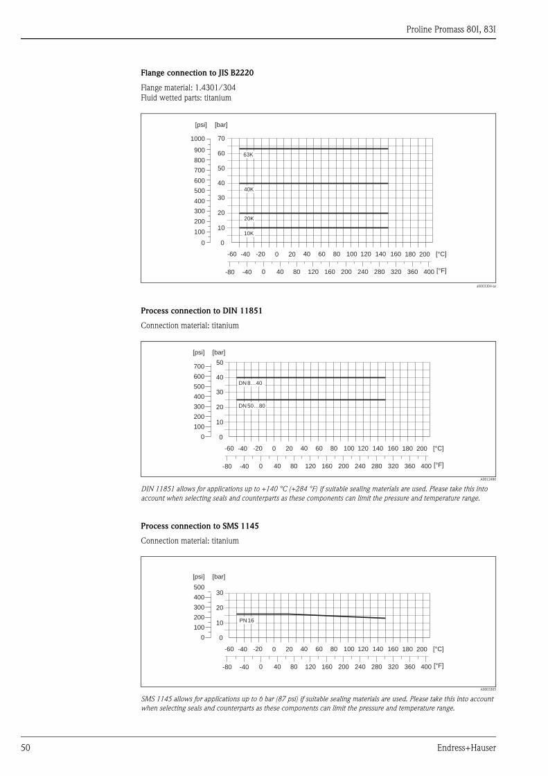
Proline Promass 80I, 83I
50 Endress+Hauser
Flange connection to JIS B2220
Flange material: 1.4301/304
Fluid wetted parts: titanium
a0003304-ae
Process connection to DIN 11851
Connection material: titanium
A0012480
DIN 11851 allows for applications up to +140 °C (+284 °F) if suitable sealing materials are used. Please take this into
account when selecting seals and counterparts as these components can limit the pressure and temperature range.
Process connection to SMS 1145
Connection material: titanium
A0003305
SMS 1145 allows for applications up to 6 bar (87 psi) if suitable sealing materials are used. Please take this into account
when selecting seals and counterparts as these components can limit the pressure and temperature range.
0
10
20
30
40
50
70
60
[bar]
-60 -40 -20 0 20 40 60 80 100 120 140 180 200160 [°C]
63K
10K
40K
20K
[psi]
200
100
400
300
500
600
700
800
900
0
1000
-40 0-80 40 80 120 160 200 240 280 320 360 400 [°F]
0
10
20
30
40
50
DN 8…40
[bar]
-60 -40 -20 0 20 40 60 80 100 120 140 180 200160 [°C]
-40 0-80 40 80 120 160 200 240 280 320 360 400 [°F]
300
400
500
700
600
200
100
0
[psi]
DN 50…80
0
10
20
30
PN 16
[bar]
-60 -40 -20 0 20 40 60 80 100 120 140 180 200160 [°C]
-40 0-80 40 80 120 160 200 240 280 320 360 400 [°F]
300
400
500
200
100
0
[psi]
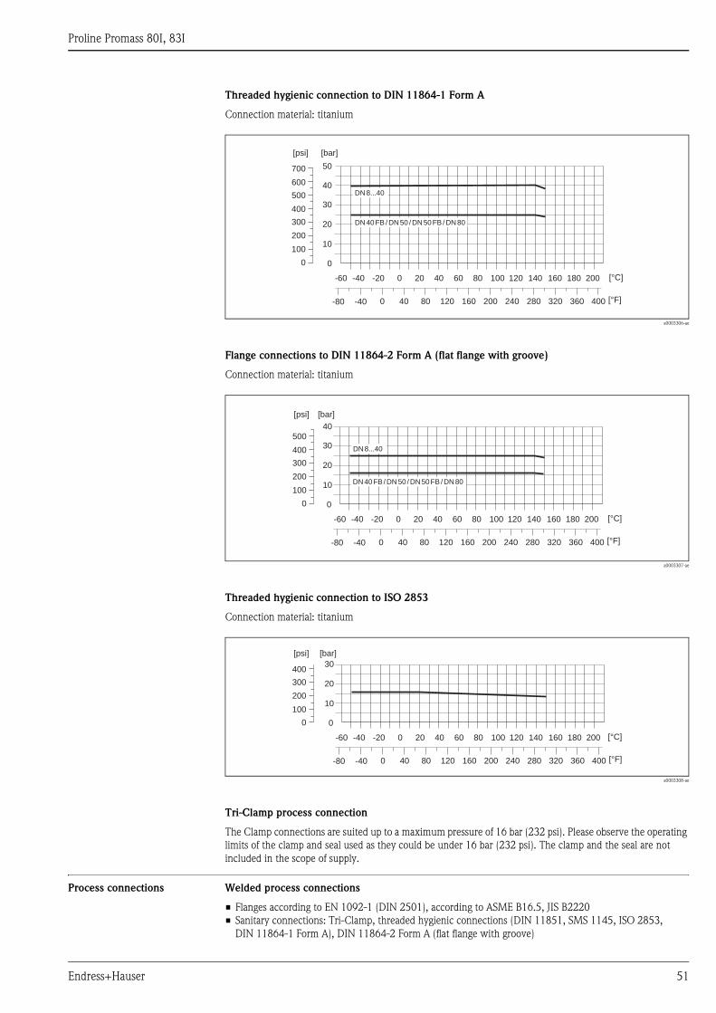
Proline Promass 80I, 83I
Endress+Hauser 51
Threaded hygienic connection to DIN 11864-1 Form A
Connection material: titanium
a0003306-ae
Flange connections to DIN 11864-2 Form A (flat flange with groove)
Connection material: titanium
a0003307-ae
Threaded hygienic connection to ISO 2853
Connection material: titanium
a0003308-ae
Tri-Clamp process connection
The Clamp connections are suited up to a maximum pressure of 16 bar (232 psi). Please observe the operating
limits of the clamp and seal used as they could be under 16 bar (232 psi). The clamp and the seal are not
included in the scope of supply.
Process connections Welded process connections
• Flanges according to EN 1092-1 (DIN 2501), according to ASME B16.5, JIS B2220
• Sanitary connections: Tri-Clamp, threaded hygienic connections (DIN 11851, SMS 1145, ISO 2853,
DIN 11864-1 Form A), DIN 11864-2 Form A (flat flange with groove)
0
10
20
30
40
50
DN 8...40
DN 40 FB /DN 50 /DN 50 FB /DN 80
[bar]
-60 -40 -20 0 20 40 60 80 100 120 140 180 200160 [°C]
[psi]
200
100
400
300
500
600
700
0
-40 0-80 40 80 120 160 200 240 280 320 360 400 [°F]
0
10
20
30
40
DN 8...40
DN 40 FB /DN 50 /DN 50 FB /DN 80
[bar]
-60 -40 -20 0 20 40 60 80 100 120 140 180 200160 [°C]
[psi]
200
100
400
300
500
0
-40 0-80 40 80 120 160 200 240 280 320 360 400 [°F]
0
10
20
30
[bar]
-60 -40 -20 0 20 40 60 80 100 120 140 180 200160 [°C]
-40 0-80 40 80 120 160 200 240 280 320 360 400 [°F]
[psi]
200
100
400
300
0

Proline Promass 80I, 83I
52 Endress+Hauser
Human interface
Display elements • Liquid-crystal display: backlit, two lines (Promass 80) or four lines (Promass 83) with 16 characters per line
• Selectable display of different measured values and status variables
• At ambient temperatures below –20 °C (–4 °F) the readability of the display may be impaired.
Operating elements Promass 80:
• Local operation with three keys (S/O/F)
• Quick Setup menus for straightforward commissioning
Promass 83:
• Local operation with three optical keys (S/O/F)
• Application-specific Quick Setup menus for straightforward commissioning
Language groups Language groups available for operation in different countries:
• Western Europe and America (WEA):
English, German, Spanish, Italian, French, Dutch and Portuguese
• Eastern Europe/Scandinavia (EES):
English, Russian, Polish, Norwegian, Finnish, Swedish and Czech
• South and Eastern Asia (SEA):
English, Japanese, Indonesian
Only Promass 83
• China (CN):
English, Chinese
The language group is changed using the "FieldCare" operating program.
Remote operation Promass 80
Remote operation via HART, PROFIBUS PA
Promass 83
Remote operation via HART, PROFIBUS PA/DP, FOUNDATION Fieldbus, MODBUS RS485
Certificates and approvals
CE mark The measuring system is in conformity with the statutory requirements of the EC Directives.
Endress+Hauser confirms successful testing of the device by affixing to it the CE mark.
C-Tick symbol The measuring system complies with the EMC requirements of the "Australian Communications and Media
Authority (ACMA)"
Ex approval Information about currently available Ex versions (ATEX, FM, CSA, IECEx, NEPSI etc.) can be supplied by your
Endress+Hauser Sales Center on request. All information relevant to explosion protection is available in
separate Ex documents that you can order as necessary.
Sanitary compatibility • 3A approval
• EHEDG tested
Proline Promass 80I, 83I
Endress+Hauser 53
FOUNDATION Fieldbus
certification
The flow device has successfully passed all the test procedures carried out and is certified and registered by the
Fieldbus Foundation. The device thus meets all the requirements of the following specifications:
• Certified to FOUNDATION Fieldbus Specification
• The device meets all the specifications of the FOUNDATION Fieldbus H1.
• Interoperability Test Kit (ITK), revision status 5.01 (device certification number: on request)
• The device can also be operated with certified devices of other manufacturers
• Physical Layer Conformance Test of the Fieldbus Foundation
PROFIBUS DP/PA
certification
The flow device has successfully passed all the test procedures carried out and is certified and registered by the
PNO (PROFIBUS User Organization). The device thus meets all the requirements of the following
specifications:
• Certified in accordance with PROFIBUS Profile Version 3.0 (device certification number: available on
request)
• The device can also be operated with certified devices of other manufacturers (interoperability)
MODBUS certification The measuring device meets all the requirements of the MODBUS/TCP conformity test and has the
"MODBUS/TCP Conformance Test Policy, Version 2.0". The measuring device has successfully passed all the
test procedures carried out and is certified by the "MODBUS/TCP Conformance Test Laboratory" of the
University of Michigan.
Other standards and
guidelines
• EN 60529
Degrees of protection by housing (IP code)
• EN 61010-1
Protection Measures for Electrical Equipment for Measurement, Control, Regulation and Laboratory
Procedures.
• IEC/EN 61326
"Emission in accordance with Class A requirements". Electromagnetic compatibility (EMC requirements).
• NAMUR NE 21
Electromagnetic compatibility (EMC) of industrial process and laboratory control equipment.
• NAMUR NE 43
Standardization of the signal level for the breakdown information of digital transmitters with analog output
signal.
• NAMUR NE 53
Software of field devices and signal-processing devices with digital electronics
Pressure Equipment Directive The measuring devices can be ordered with or without PED (Pressure Equipment Directive). If a device with
PED is required, this must be ordered explicitly. For devices with nominal diameters less than or equal to
DN 25 (1"), this is neither possible nor necessary.
• With the identification PED/G1/III on the sensor nameplate, Endress+Hauser confirms conformity with the
"Basic safety requirements" of Appendix I of the Pressure Equipment Directive 97/23/EC.
• Devices with this identification (with PED) are suitable for the following types of fluid:
– Fluids of Group 1 and 2 with a steam pressure of greater or less than 0.5 bar (7.3 psi)
– Unstable gases
• Devices without this identification (without PED) are designed and manufactured according to good
engineering practice. They correspond to the requirements of Art. 3, Section 3 of the Pressure Equipment
Directive 97/23/EC. Their application is illustrated in Diagrams 6 to 9 in Appendix II of the Pressure
Equipment Directive 97/23/EC.
Proline Promass 80I, 83I
54 Endress+Hauser
Functional safety SIL -2: accordance IEC 61508/IEC 61511-1 (FDIS)
"4–20 mA HART" output according to the following order code:
Promass 80
Promass 83
Ordering informationThe Endress+Hauser service organization can provide detailed ordering information and information on the
order codes on request.
AccessoriesVarious accessories, which can be ordered separately from Endress+Hauser, are available for the transmitter
and the sensor.
Documentation• Flow measuring technology (FA005D)
• Technical Information
– Promass 80A, 83A (T054D)
– Promass 80E, 83E (TI061D)
– Promass 80F, 83F (TI101D)
– Promass 80H, 83H (TI074D
– Promass 80M, 83M (TI102D)
– Promass 80P, 83P (TI078D)
– Promass 80S, 83S (TI076D)
• Operating Instructions/Description of Device Functions
– Promass 80 (BA057D/BA058D)
– Promass 80 PROFIBUS PA (BA072D/BA073D)
– Promass 83 HART (BA059D/BA060D)
– Promass 83 FOUNDATION Fieldbus (BA065D/BA066D)
– Promass 83 PROFIBUS DP/PA (BA063D/BA064D)
– Promass 83 MODBUS (BA107D/BA108D)
• Supplementary documentation on Ex-ratings: ATEX, FM, CSA, IECEx NEPSI
• Functional safety manual Promass 80, 83 (SD077D)
Promass80***-************A
Promass80***-************D
Promass80***-************S
Promass80***-************T
Promass80***-************8
Promass83***-************A
Promass83***-************B
Promass83***-************C
Promass83***-************D
Promass83***-************E
Promass83***-************L
Promass83***-************M
Promass83***-************R
Promass83***-************S
Promass83***-************T
Promass83***-************U
Promass83***-************W
Promass83***-************Ø
Promass83***-************2
Promass83***-************3
Promass83***-************4
Promass83***-************5
Promass83***-************6

Proline Promass 80I, 83I
Endress+Hauser 55
Registered trademarksKALREZ® and VITON®
Registered trademarks of E.I. Du Pont de Nemours & Co., Wilmington, USA
TRI-CLAMP ®
Registered trademark of Ladish & Co., Inc., Kenosha, USA
SWAGELOK ®
Registered trademark of Swagelok & Co., Solon, USA
HART®
Registered trademark of HART Communication Foundation, Austin, USA
PROFIBUS®
Registered trademark of the PROFIBUS User Organization, Karlsruhe, Germany
FOUNDATION™ Fieldbus
Registered trademark of the Fieldbus FOUNDATION, Austin, USA
MODBUS®
Registered trademark of the MODBUS Organization
HistoROM™, S-DAT®, T-DAT™, F-CHIP®, Fieldcheck®, FieldCare®, Applicator®
Registered or registration-pending trademarks of Endress+Hauser Flowtec AG, Reinach, CH

Instruments International
Endress+HauserInstruments International AGKaegenstrasse 24153 ReinachSwitzerland
Tel. +41 61 715 81 00Fax +41 61 715 25 [email protected]
TI075D/06/en/05.10
71116468
FM+SGML6.0ProMoDo