project to implement a processing plant for spent
TRANSCRIPT
Project to implement a processing plant for spent potlining in Jonquière
Comprehensive Study Report (document prepared by Tecsult Inc.)
JANUARY 2006
Project to implement a processing plant for spent potlining in Jonquière i Comprehensive Study Report
TABLE OF CONTENT page
1 SUMMARY................................................................................................................... 1-1 1.1 Background.................................................................................................................. 1-1 1.2 The Issue ..................................................................................................................... 1-1 1.3 Project Description....................................................................................................... 1-2
1.3.1 Construction.............................................................................................. 1-2 1.3.2 Operating Activities ................................................................................... 1-2 1.3.2.1 Pot Lining Processing ............................................................................... 1-2 1.3.2.2 Recovering the Condensate ..................................................................... 1-3 1.3.2.3 Vapour Production .................................................................................... 1-3 1.3.2.4 Cooling Tower........................................................................................... 1-3 1.3.3 Supply and Transportation........................................................................ 1-4 1.3.4 Storage Site .............................................................................................. 1-4
1.4 Alternatives and Implementation Methods ................................................................... 1-4 1.5 Public Consultation ...................................................................................................... 1-5
1.5.1 By the Proponent ...................................................................................... 1-5 1.5.2 Quebec’s Environment Quality Act ........................................................... 1-5 1.5.3 Canadian Environmental Assessment Act ................................................ 1-5
1.6 Description of the Receiving Environment ................................................................... 1-6 1.6.1 Physical Environment ............................................................................... 1-6 1.6.1.1 Hydrography ............................................................................................. 1-6 1.6.1.2 Industrial Waste Disposal Sites................................................................. 1-6 1.6.1.3 Atmospheric Environment ......................................................................... 1-6 1.6.1.4 Noise Environment.................................................................................... 1-7 1.6.1.5 Flora and Fauna........................................................................................ 1-7
1.7 Human Environment .................................................................................................... 1-8 1.8 Impacts and Mitigation Measures ................................................................................ 1-8
1.8.1 Soil, Surface Water and Groundwater: Operations................................... 1-8 1.8.2 Atmospheric Environment ......................................................................... 1-9 1.8.2.1 Construction Period .................................................................................. 1-9 1.8.2.2 Operating Period....................................................................................... 1-9 1.8.2.3 Cumulative Impacts .................................................................................. 1-9 1.8.3 Greenhouse Effect .................................................................................. 1-10 1.8.4 Hydrology and Water Quality .................................................................. 1-10 1.8.4.1 Water Resources .................................................................................... 1-10 1.8.4.2 Impacts of Liquid Discharges.................................................................. 1-11 1.8.5 Waste Management Site......................................................................... 1-11 1.8.6 Ambient Noise Environment ................................................................... 1-11 1.8.7 Biological Environment ........................................................................... 1-12 1.8.8 Human Environment ............................................................................... 1-12 1.8.8.1 Traffic ...................................................................................................... 1-12 1.8.8.2 Aesthetics and Landscape...................................................................... 1-12 1.8.8.3 Psychosocial Impact ............................................................................... 1-12 1.8.8.4 Health...................................................................................................... 1-12 1.8.9 Security ................................................................................................... 1-13 1.8.9.1 Security Measures .................................................................................. 1-13 1.8.9.2 Emergency Response Plan .................................................................... 1-14

Project to implement a processing plant for spent potlining in Jonquière ii Comprehensive Study Report
TABLE OF CONTENT page
1.8.10 Economic Spinoffs .................................................................................. 1-14 1.9 Monitoring and Follow-Up Program ........................................................................... 1-18 2 INTRODUCTION.......................................................................................................... 2-1 3 PROJECT DESCRIPTION........................................................................................... 3-1 3.1 Description of the Processing Plant’s Technical Features ........................................... 3-1
3.1.1 Development and Construction Activities.................................................. 3-1 3.1.1.1 Construction Work .................................................................................... 3-1 3.1.1.2 Raw Water Supply for the Plant ................................................................ 3-2 3.1.1.3 Leachates ................................................................................................. 3-2 3.1.1.4 Natural Gas Supply................................................................................... 3-3 3.1.1.5 Electrical Supply ....................................................................................... 3-3 3.1.1.6 Vapour Supply .......................................................................................... 3-3 3.1.1.7 Schedule ................................................................................................... 3-3 3.1.2 Operational Activities at the Plant ............................................................. 3-3 3.1.2.1 Processing Capacity ................................................................................. 3-8 3.1.2.2 Storage of Raw Materials.......................................................................... 3-8 3.1.2.3 Crushing.................................................................................................... 3-9 3.1.2.4 Water and Caustic Leaching................................................................... 3-10 3.1.2.5 Cyanide Destruction................................................................................ 3-11 3.1.2.6 Evaporation, Crystallization and Causticization ...................................... 3-11 3.1.2.7 Recovering the Condensate ................................................................... 3-12 3.1.2.8 Vapour Production .................................................................................. 3-12 3.1.2.9 Cooling Tower......................................................................................... 3-12
3.2 Description of Waste and Hazards............................................................................. 3-12 3.2.1 Mass Balance ......................................................................................... 3-12 3.2.2 Air Emissions .......................................................................................... 3-16 3.2.2.1 Description .............................................................................................. 3-16 3.2.2.2 Respecting Discharge Standards............................................................ 3-19 3.2.3 Liquid Discharges ................................................................................... 3-20 3.2.4 Solid Discharges ..................................................................................... 3-24 3.2.4.1 Iron Oxides.............................................................................................. 3-24 3.2.4.2 Descaling Residues ................................................................................ 3-25 3.2.4.3 Carbon and Inert Materials...................................................................... 3-25
3.3 Supplies, Transportation and Traffic .......................................................................... 3-25 3.3.1 Supply of Spent Pot Lining...................................................................... 3-25 3.3.2 Transportation Requirements.................................................................. 3-26 3.3.2.1 Supply Sources of Spent Pot Lining........................................................ 3-26 3.3.2.2 Waste Disposal ....................................................................................... 3-32 3.3.3 Distribution of Travel on Transportation Networks .................................. 3-33
3.4 Carbon and Inert Material Storage Site...................................................................... 3-39 3.4.1 Background............................................................................................. 3-39 3.4.2 Site Description....................................................................................... 3-39 3.4.3 Description of Development .................................................................... 3-39 3.4.4 Construction Phases............................................................................... 3-49 3.4.5 Waste Storage ........................................................................................ 3-49 3.4.6 Covers..................................................................................................... 3-50 3.4.7 Managing Leachates............................................................................... 3-51

Project to implement a processing plant for spent potlining in Jonquière iii Comprehensive Study Report
TABLE OF CONTENT page
3.4.8 Waste Recovery...................................................................................... 3-52 3.5 Decommissioning and Rehabilitating the Site............................................................ 3-52 4 ALTERNATIVES AND IMPLEMENTATION METHODS.............................................. 4-1 4.1 Project rationale ........................................................................................................... 4-1 4.2 Background.................................................................................................................. 4-1
4.2.1 Spent Pot Lining as a Hazardous Material................................................ 4-1 4.2.2 Current State of Spent Pot Lining Management in Quebec ...................... 4-1
4.3 Management Options................................................................................................... 4-2 4.3.1 Reduction at the Source ........................................................................... 4-2 4.3.2 Reuse........................................................................................................ 4-3 4.3.3 Recycling .................................................................................................. 4-3 4.3.4 Upgrading ................................................................................................. 4-3 4.3.5 Disposal .................................................................................................... 4-3
4.4 Technological Choices................................................................................................. 4-3 4.4.1 Technologies Being Contemplated ........................................................... 4-3 4.4.1.1 Pyrometallurgical Processes..................................................................... 4-4 4.4.1.2 Hydrometallurgical Processes................................................................... 4-5 4.4.1.3 Technology Comparison ........................................................................... 4-5
4.5 Preferred Technology................................................................................................... 4-6 4.5.1 Economic and Technical Issues ............................................................... 4-6 4.5.1.1 Pilot Tests ................................................................................................. 4-7 4.5.1.2 Advantages of the LCLL Process.............................................................. 4-8 4.5.1.3 Economic Feasibility ................................................................................. 4-8 4.5.2 Environmental and Socio-political Issues.................................................. 4-9
5 SCOPE OF THE STUDY ............................................................................................. 5-1 5.1 Scope of the Project..................................................................................................... 5-1 5.2 Factors to be Considered............................................................................................. 5-1 5.3 Scope of the Factors to be Considered........................................................................ 5-2
5.3.1 Any Change to the Project Attributable to the Environment...................... 5-3 5.3.2 Accidents or Malfunctions ......................................................................... 5-3 5.3.3 Cumulative Environmental Effects ............................................................ 5-3 5.3.4 Renewable Resources.............................................................................. 5-3 5.3.5 Spatial and Temporal Boundaries............................................................. 5-4 5.3.6 Proposed Design of the Follow-up Program ............................................. 5-4
6 PUBLIC CONSULTATION........................................................................................... 6-1 6.1 Introduction .................................................................................................................. 6-1 6.2 Alcan Consultations ..................................................................................................... 6-1
6.2.1 Scope of the1997 Consultations ............................................................... 6-1 6.2.2 Community Concerns Based on Analysis of the Questions...................... 6-2 6.2.3 Public Participation Approach and Communication Activities (2000-
2001)......................................................................................................... 6-6 6.3 Government Consultations........................................................................................... 6-7 7 DESCRIPTION OF THE RECEIVING ENVIRONMENT .............................................. 7-1 7.1 Site Pre-selection and Selection .................................................................................. 7-1 7.2 Delineation of the Study Area ...................................................................................... 7-2 7.3 Biophysical Environment Components ........................................................................ 7-2

Project to implement a processing plant for spent potlining in Jonquière iv Comprehensive Study Report
TABLE OF CONTENT page
7.3.1 Physical Environment Components .......................................................... 7-2 7.3.1.1 Land Topography...................................................................................... 7-2 7.3.1.2 Regional Geology ..................................................................................... 7-2 7.3.1.3 Seismicity.................................................................................................. 7-3 7.3.1.4 Surface Materials ...................................................................................... 7-3 7.3.1.5 Hydrography ............................................................................................. 7-4 7.3.1.6 Hydrogeology............................................................................................ 7-4 7.3.1.7 Groundwater Quality ................................................................................. 7-5 7.3.1.8 Industrial Waste Removal Locations......................................................... 7-5 7.3.2 Atmosphere............................................................................................... 7-5 7.3.3 Regional Climate..................................................................................... 7-10 7.3.3.1 Choice of Weather Station ...................................................................... 7-10 7.3.3.2 Winds ...................................................................................................... 7-10 7.3.3.3 Temperature ........................................................................................... 7-10 7.3.3.4 Precipitation ............................................................................................ 7-11 7.3.4 Surrounding Noise Environment ............................................................. 7-20 7.3.4.1 Location of the Measurement Points....................................................... 7-20 7.3.4.2 Nature of the Measurements .................................................................. 7-20 7.3.4.3 Measuring Instrumentation ..................................................................... 7-20 7.3.4.4 Weather Conditions ................................................................................ 7-23 7.3.4.5 Noise Environment During the Day......................................................... 7-23 7.3.4.6 Noise Environment During the Night....................................................... 7-24 7.3.5 Flora and Fauna...................................................................................... 7-29 7.3.5.1 Vegetation............................................................................................... 7-29 7.3.5.2 Wetlands ................................................................................................. 7-29 7.3.5.3 Wildlife .................................................................................................... 7-29 7.3.5.4 Endangered Species............................................................................... 7-32
7.4 Human Environment Components ............................................................................. 7-32 7.4.1 Regional Setting...................................................................................... 7-32 7.4.2 Socio-economic Profile ........................................................................... 7-35 7.4.3 Characterization of the Study Area ......................................................... 7-35 7.4.3.1 Use by Non-Aboriginal People................................................................ 7-35 7.4.3.2 Use by Aboriginal People........................................................................ 7-36 7.4.4 Infrastructure and Equipment.................................................................. 7-41 7.4.4.1 Rail Network............................................................................................ 7-41 7.4.4.2 Road Network ......................................................................................... 7-41 7.4.4.3 Water, Sewer, Electrical and Gas Systems ............................................ 7-42
7.5 Archaeological Potential............................................................................................. 7-43 7.5.1 Geographic and Geomorphic Context..................................................... 7-43 7.5.2 History of the Area .................................................................................. 7-43 7.5.3 Aboriginal Way of Life ............................................................................. 7-44 7.5.4 Archaeological Potential of the Plant Site ............................................... 7-44 7.5.4.1 Prehistoric Period.................................................................................... 7-44 7.5.4.2 Historical Period...................................................................................... 7-44 7.5.4.3 Conclusion .............................................................................................. 7-44
8 IMPACT AND MITIGATION MEASURE ANALYSIS.................................................... 8-1 8.1 Impacts on the Natural Environment............................................................................ 8-1
Project to implement a processing plant for spent potlining in Jonquière v Comprehensive Study Report
TABLE OF CONTENT page
8.1.1 Components of the Physical Environment ................................................ 8-1 8.1.1.1 Soil, Surface Water and Groundwater: Possibility of an Accidental
Spill at the Site.......................................................................................... 8-1 8.1.1.2 Soil, Surface Water and Groundwater: Possibility of an Accidental
Spill During the Transportation of Materials.............................................. 8-2 8.1.1.3 Soil, Surface Water and Groundwater: Operating Activities ..................... 8-2 8.1.2 Atmospheric Environment ......................................................................... 8-3 8.1.2.1 Construction Period .................................................................................. 8-3 8.1.2.2 Operating Period....................................................................................... 8-3 8.1.2.3 Method ...................................................................................................... 8-3 8.1.2.4 Results – Total Concentrations of Suspended Particulates ...................... 8-5 8.1.2.5 Results - Concentrations of Fine Particulates......................................... 8-13 8.1.2.6 Results – Ammonia Concentrations........................................................ 8-15 8.1.2.7 Results - SO2 Concentrations ................................................................. 8-18 8.1.2.8 Results - Concentrations of Carbon Monoxide (CO)............................... 8-26 8.1.2.9 Results – Concentrations of Nitrogen Dioxide (NO2) .............................. 8-29 8.1.3 Greenhouse Gas..................................................................................... 8-32 8.1.4 Hydrology and Water Quality .................................................................. 8-32 8.1.4.1 Use of Water Resources......................................................................... 8-32 8.1.4.2 Impacts Related to Liquid Discharges..................................................... 8-33 8.1.5 Waste Management Site......................................................................... 8-34 8.1.6 Ambient Noise......................................................................................... 8-34 8.1.6.1 Projection Calculation Method ................................................................ 8-34 8.1.6.2 Characterization of Impact Sources........................................................ 8-36 8.1.7 Impact Analysis on Ambient Noise.......................................................... 8-37 8.1.7.1 Impacts Linked to the Stationary Sources Used for the Operation of
the Plant.................................................................................................. 8-37 8.1.7.2 Impacts of Noise of Transportation and Shipping of Raw Materials ....... 8-41 8.1.7.3 Noise Impacts Linked to the Storage Site and to Transportation
Activities Inside the Property .................................................................. 8-41 8.1.8 Wetlands ................................................................................................. 8-45 8.1.9 Biological Environment ........................................................................... 8-45 8.1.9.1 Vegetation............................................................................................... 8-45 8.1.9.2 Fish, terrestrial and avian fauna and wildlife habitats ............................. 8-45 8.1.9.3 Endangered species ............................................................................... 8-45
8.2 Human Environment .................................................................................................. 8-45 8.2.1 Transportation and Traffic ....................................................................... 8-45 8.2.1.1 Impact of Resulting Traffic on General Traffic......................................... 8-45 8.2.1.2 Road Safety ............................................................................................ 8-46 8.2.2 Aesthetics and Landscape...................................................................... 8-46 8.2.2.1 Pot Lining Processing Plant .................................................................... 8-46 8.2.2.2 Carbon and Inert Temporary Storage Site .............................................. 8-46 8.2.3 Psychosocial Impact ............................................................................... 8-49
8.3 Health......................................................................................................................... 8-49 8.3.1 Direct Effects........................................................................................... 8-49 8.3.2 Incidences from Cumulative Effects........................................................ 8-50
8.4 Safety ......................................................................................................................... 8-50 8.4.1 Identification of Danger ........................................................................... 8-51

Project to implement a processing plant for spent potlining in Jonquière vi Comprehensive Study Report
TABLE OF CONTENT page
8.4.2 Identification of Sensitive Elements ........................................................ 8-52 8.4.3 Review of Passed Accidents................................................................... 8-52 8.4.4 Standardized Scenario............................................................................ 8-53 8.4.4.1 Definition of a Standardized Scenario..................................................... 8-53 8.4.4.2 Assessment of the Consequences of a Standardized Scenario ............. 8-53 8.4.5 Other Scenarios ...................................................................................... 8-58 8.4.5.1 Crushed Pot Lining Silo .......................................................................... 8-61 8.4.5.2 Leaching Gas.......................................................................................... 8-61 8.4.5.3 Pot Lining Container ............................................................................... 8-62 8.4.5.4 Defect of the Acid Supply System........................................................... 8-62 8.4.6 Discussion on External Dangers ............................................................. 8-63 8.4.6.1 Natural Phenomenons ............................................................................ 8-63 8.4.6.2 Industrial Activities .................................................................................. 8-63 8.4.7 Conclusion .............................................................................................. 8-64
8.5 Safety Measures ........................................................................................................ 8-64 8.5.1 General Design Parameters.................................................................... 8-64 8.5.2 Access Restriction to the Site ................................................................. 8-64 8.5.3 Receiving and Handling Spent Pot Lining............................................... 8-64 8.5.4 Leaching ................................................................................................. 8-65 8.5.5 Safety Installations.................................................................................. 8-65 8.5.6 Emergency Shutdown............................................................................. 8-66 8.5.7 Fire-Control Systems .............................................................................. 8-66 8.5.8 Preliminary Risk Management Program ................................................. 8-67 8.5.8.1 Staff Protection ....................................................................................... 8-67 8.5.8.2 Health and Safety Management Program............................................... 8-67 8.5.8.3 External Services Interventions (Contractors)......................................... 8-68 8.5.8.4 Critical Review Program.......................................................................... 8-68 8.5.8.5 Preventive and Predictive Maintenance Program................................... 8-68 8.5.8.6 Health and Safety Auditing Program....................................................... 8-68 8.5.9 List of Regulations and Codes ................................................................ 8-69
8.6 Emergency Response Plan........................................................................................ 8-70 8.7 Economic Spinoffs ..................................................................................................... 8-71
8.7.1 Economic Impacts Resulting from Construction Activities ...................... 8-71 8.7.1.1 Impacts for the Province of Quebec........................................................ 8-71 8.7.1.2 Impacts for the Saguenay - Lac-Saint-Jean Region ............................... 8-72 8.7.2 Annual Impacts resulting from Operating Activities................................. 8-73 8.7.2.1 Impacts for the Province of Quebec........................................................ 8-73 8.7.2.2 Impacts for Saguenay - Lac-Saint-Jean.................................................. 8-73 8.7.3 Economic Impact Maximisation Strategy ................................................ 8-74
8.8 Heritage, Cultural, Historic, Archaeological, Paleontological Resources ................... 8-74 8.9 Land and Resource Use by Aboriginals and Land Claims......................................... 8-74 8.10 Renewable resources ................................................................................................ 8-74
8.10.1 Use of the space ..................................................................................... 8-74 8.10.2 Upgrading of materials ............................................................................ 8-74
9 SIGNIFICANCE OF IMPACTS..................................................................................... 9-1 9.1 Impact Identification and Assessment Method............................................................. 9-1 9.2 Impact Summary .......................................................................................................... 9-3

Project to implement a processing plant for spent potlining in Jonquière vii Comprehensive Study Report
TABLE OF CONTENT page
10 MONITORING AND FOLLOW-UP SYSTEM ............................................................. 10-1 10.1 Work Monitoring ......................................................................................................... 10-1
10.1.1 Processing Plant ..................................................................................... 10-1 10.1.2 Carbon and Inert Storage Cell ................................................................ 10-1 10.1.2.1 Qualification of Stakeholders .................................................................. 10-1 10.1.2.2 Quality of Other Materials Used.............................................................. 10-1
10.2 Discharge Monitoring ................................................................................................. 10-1 10.2.1 Air Emissions .......................................................................................... 10-2 10.2.2 Liquid Discharges ................................................................................... 10-2 10.2.3 Solid Discharges ..................................................................................... 10-3
10.3 Environmental Follow-up............................................................................................ 10-3 10.3.1 Noise Environment.................................................................................. 10-3 10.3.2 Atmospheric Environment ....................................................................... 10-4 10.3.3 Inert and Carbon Storage Cell ................................................................ 10-4 10.3.4 Result Dissemination .............................................................................. 10-4 10.3.4.1 Follow-up Committee .............................................................................. 10-4

Project to implement a processing plant for spent potlining in Jonquière viii Comprehensive Study Report
TABLE OF CONTENT page
LIST OF APPENDICES Appendix A Jonquière Complex Drawing Appendix B General Plan Appendix C Material Safety Data Sheets Appendix D Letter from the MENV – Ambient Air Criteria Appendix E Data and Results from Atmospheric Emission Modellings
Appendix E-1 Topographic Table Appendix E-2 Building-related Data Appendix E 3 Emission-related Data Appendix E-4 Results - Particulates Appendix E-5 Results – NH3 Appendix E-6 Wind Rose
Appendix F Drawings of Atmospheric Emission Sources - Plan View and Elevation Drawing
Project to implement a processing plant for spent potlining in Jonquière ix Comprehensive Study Report
TABLE OF CONTENT page
LIST OF FIGURES Figure 3.1.1 Schematic Diagram of the SPL Processing Plant........................................ 3-4 Figure 3.1.2 Services Diagram ........................................................................................ 3-6 Figure 3.2.1 Mass Balance ............................................................................................ 3-14 Figure 3.2.2 Location of Outfall Sewers at the Jonquière Complex ............................... 3-22 Figure 3.3.1 Spent Pot Lining Supply Sources .............................................................. 3-28 Figure 3.3.2 Carrier Modes for Spent Pot Lining............................................................ 3-30 Figure 3.3.3 Distribution of Travel on the Road Network ............................................... 3-35 Figure 3.3.4 Container Used to Transport Spent Pot Lining .......................................... 3-37 Figure 3.4.1 Storage Site – Location Plan ..................................................................... 3-40 Figure 3.4.2 Storage Site – Layout Overview ................................................................ 3-42 Figure 3.4.3 Top View of the Storage Cell ..................................................................... 3-44 Figure 3.4.4 Cross-Sectional View of the Storage Cell .................................................. 3-46 Figure 3.4.5 Detail Drawing - Profile of the Foot of the Waste Heap ............................. 3-51 Figure 7.3.1 Location of the Parc Berthier Air Quality Measurement Station in
Jonquière ..................................................................................................... 7-7 Figure 7.3.2 Wind Direction Frequencies (1996-2000) .................................................. 7-12 Figure 7.3.3 Wind Speed Variation According to the Direction the Wind is Coming
from (1996-2000) ....................................................................................... 7-14 Figure 7.3.4 Average Monthly Temperatures (1996-2000) ............................................ 7-16 Figure 7.3.5 Average Monthly Precipitation (1961-1990)............................................... 7-18 Figure 7.3.6 Location of Noise Environment Measurement Points ................................ 7-21 Figure 7.3.7 Temporal Noise Trends at 2310 Hébert Street .......................................... 7-27 Figure 7.4.1 Regional Site and Location of Aluminium Plants ....................................... 7-33 Figure 7.4.2 Land Use and Allocation............................................................................ 7-37 Figure 7.4.3 Land Use in the Chemin de la Réserve Sector.......................................... 7-39 Figure 8.1.1 Annual Average Particulate Concentrations (µg/m3) – Year 2000............... 8-7 Figure 8.1.2 Trend for Average Total Particulate and PM 10 Particulates
Concentrations (Annual Averages) at the Parc Berthier Station in Jonquière ................................................................................................... 8-11
Figure 8.1.3 Estimated Trend for the 98th Percentile of Fine Particulates (PM 2.5) at the Parc Berthier Station in Jonquière ................................................... 8-16
Figure 8.1.4 Annual Average Concentrations of NH3 (µg/m3) –1996............................. 8-19 Figure 8.1.5 Hourly Maximum Concentrations of NH3 (µg/m3) –1998............................ 8-21 Figure 8.1.6 Annual Maximum Concentrations of SO2 (µg/m3) – 2000.......................... 8-24 Figure 8.1.7 Annual Average Concentrations of CO (µg/m3) – 2000 ............................. 8-27 Figure 8.1.8 Annual Average Concentrations of NO2 (µg/m3) – 2000............................ 8-30 Figure 8.1.9 Leq24h Isophon Map ................................................................................... 8-39 Figure 8.2.1 Temporary Storage Site for Inert Wastes – Impact on the Landscape...... 8-47 Figure 8.4.1 Standardized Scenario– Toxic Gas Release ............................................. 8-55 Figure 8.4.2 Standardized Scenario – Explosion........................................................... 8-59

Project to implement a processing plant for spent potlining in Jonquière x Comprehensive Study Report
TABLE OF CONTENT page
LIST OF TABLES Table 1.6.1 Concentration of Pollutants in the Ambient Air Measured at the Parc
Berthier Station (02016) Between 1996 and 2003....................................... 1-7 Table 1.8.1 Modeled Concentrations of Pollutants in the Ambient Air (Maximum
Point of Impact).......................................................................................... 1-10 Table 1.8.2 Impacts and Mitigation Measures Summary.............................................. 1-15 Table 3.1.1 Raw Materials – Annual Quantities.............................................................. 3-8 Table 3.2.1 Typical Composition of Spent Pot Lining ................................................... 3-13 Table 3.2.2 Sources of Air Emissions – Conditions and Emission Rates ..................... 3-16 Table 3.2.3 Particulate Discharges into the Air – Respecting Standards ..................... 3-19 Table 3.2.4 Liquid Discharges ...................................................................................... 3-20 Table 3.2.5 Typical Analysis – Boiler Water Flushes.................................................... 3-21 Table 3.2.6 Planned Composition – Flushes from the Cooling Water System ............. 3-24 Table 3.2.7 Colloidal Iron Oxide Waste – Approximate Composition ........................... 3-24 Table 3.2.8 Solid Waste – Estimated Annual Quantities .............................................. 3-25 Table 3.3.1 Transportation Requirements Generated by the Spent Pot Lining
Supply Sources.......................................................................................... 3-32 Table 3.3.2 Transportation Requirements Generated by Solid Waste Disposal........... 3-33 Table 3.3.3 Number of Trucks Circulating on a Normal Day and a Peak Day.............. 3-34 Table 4.44.1 Comparing Hydrometallurgic and Pyrometallurgic Processes..................... 4-5 Table 5.3.1 Factors to be Considered ............................................................................ 5-2 Table 7.3.1 Features of the Air Quality Measurement Station in Jonquière ................... 7-6 Table 7.3.2 Concentration of Ambient Airborne Particulates Measured at the Parc
Berthier Station (02016)............................................................................... 7-6 Table 7.3.3 Concentration of Ambient Airborne Particulates Smaller Than 10 µm
(PM 10) Measured at the Parc Berthier Station (02016).............................. 7-9 Table 7.3.4 Concentration of Sulphur Dioxide Measured in Ambient Air at the Parc
Berthier Station (02016)............................................................................... 7-9 Table 7.3.5 Weather Conditions During the Main Measurement Periods..................... 7-23 Table 7.3.6 Results of Noise Measurements Taken During the Day (dBA).................. 7-23 Table 7.3.7 Results of Noise Measurements Taken at Night (dBA) ............................. 7-25 Table 7.3.8 Species of Mammals Likely to be Found in Urban, Peri-urban and
Agricultural Areas ...................................................................................... 7-31 Table 7.3.9 Birds Likely to be Found in Urban and Peri-urban Areas in the
Saguenay-Lac-Saint-Jean Region............................................................. 7-31 Table 7.4.1 Jobs Within Companies by Area of Activity in Saguenay .......................... 7-35 Table 8.1.1 Total Modelled Maximum Particulate Concentrations.................................. 8-6 Table 8.1.2 Comparison of Maximum Modelled Particulate Concentrations at the
Parc Berthier Station with Measured Results from 1996 to 2000 .............. 8-10 Table 8.1.3 Modelled Concentrations of Particulates Smaller than 2,5 µm (PM 2,5) ... 8-13 Table 8.1.4 Modelled Concentration of Particulates Smaller than 2.5 µm (PM 2.5)
at the Parc Berthier Station........................................................................ 8-14 Table 8.1.5 Modelled Maximum Concentrations of Ammonia ...................................... 8-15 Table 8.1.6 Modelled Maximum Concentrations of SO2 ............................................... 8-23 Table 8.1.7 Modelled Maximum Concentrations of CO ................................................ 8-26 Table 8.1.8 Modelled Maximum Concentrations of NO2............................................... 8-29 Table 8.1.9 Source Noise Levels Considered for the Simulations................................ 8-36

Project to implement a processing plant for spent potlining in Jonquière xi Comprehensive Study Report
TABLE OF CONTENT page
Table 8.1.10 Levels of Noise Anticipated During the Day and Resulting Increases at the Measurement Points Considered (dBA) .......................................... 8-38
Table 8.1.11 Level of Noise Anticipated at Night and Resulting Increases at the Measurement Points Considered (dBA) .................................................... 8-41
Table 8.1.12 Noise Levels (Leq1h) Resulting from the Development of the Storage Site and the Transportation of Materials (dBA).......................................... 8-43
Table 8.1.13 Noise Levels (Leq1h) Resulting from the Operation of the Storage Site and Transportation (dBA)........................................................................... 8-44
Table 8.3.1 Effect Rate of Certain Pathologies (per 100,000 Inhabitants).................... 8-49 Table 8.4.1 Results – Toxic Gas Release..................................................................... 8-54 Table 8.4.2 Results – Explosion in the Silo................................................................... 8-58 Table 8.7.1 Plant Construction – Main Expenditure Items (in Millions of Dollars) ........ 8-71 Table 8.7.2 Regional Economic Impacts Related to the Plant Construction (in
Millions of Dollars)...................................................................................... 8-73 Table 9.1.1 Environmental Resistance Estimation Matrix............................................... 9-2 Table 9.1.2 Impact Significance Estimation Matrix ......................................................... 9-3 Table 9.2.1 Impacts and Mitigation Measures Summary................................................ 9-4 Table 10.2.1 Monitoring Program – Air Emissions.......................................................... 10-2 Table 10.2.2 Monitoring Program – Liquid Discharges................................................... 10-3

Project to Implement a Processing Plant for Spent Pot Lining in Jonquière 1-1 Comprehensive Study Report
1 SUMMARY
This section outlines the main elements from each part of the environmental impact assessment for the project to implement a processing plant for spent pot lining in Jonquière.
1.1 Background
Alcan Primary Metal Group (Alcan or the proponent) submitted a funding request to Technology Partnerships Canada (a division of Industry Canada) for its "project to implement a processing plant for spent pot lining" (the project), at its Jonquière complex in Saguenay, in the Saguenay-Lac-Saint-Jean region and the Le Fjord-du-Saguenay RCM, near the Alcan aluminium smelters. The proposed project consists of constructing and operating a full-scale pilot plant for the processing of spent pot lining (SPL) with an approximate capacity of 80,000 tons/year. The plant will use a chemical process developed by Alcan, called "Low Concentration Caustic Leaching and Liming" (LCLL), that enables the company to process SPL in order to convert it into a non-hazardous waste and to recycle and upgrade some products derived from this treatment. The project is subject to the federal environmental assessment process under the Canadian Environmental Assessment Act. This document details the comprehensive environmental impact assessment of the proponent’s project, as required by the Canadian Environmental Assessment Act. This document was developed from the environmental impact assessment conducted in 2001 as per the requirements of Quebec’s Ministère de l’environnement. This assessment is intended to address all the various points enumerated in the project’s Environmental Assessment Scoping Document.
1.2 The Issue
Pot lining is the interior coating of the electrolytic cells used to produce aluminium. This lining is composed of insulating and refractory bricks and carbon blocks. Throughout the electrolytic process, this lining absorbs a certain amount of the electrolyte’s components. The lining must be replaced every three to eight years. The internal pot lining (spent pot lining or SPL) is therefore removed and stored in a site designed specifically for this purpose. According to Quebec’s Regulation respecting hazardous materials (Q-2, r.15.2), spent pot lining is considered a hazardous material because it is leachable, and because it can, in certain conditions, generate a flammable and toxic gas. In fact, SPL contains leachable fluorides and cyanides, and the presence of various chemical products gives it properties that are reactive to water. The pot lining is also corrosive because of the presence of sodium compounds, which also raises the pH of any leachate. Despite efforts made by aluminium smelters to reduce the amount of SPL being generated, some 55,000 tons are generated in Quebec each year. Nearly one-half of this tonnage comes from Alcan’s aluminium smelters. Alcan has been safely storing SPL in Jonquière since 1980. During the October 2001 to November 2003 period, Alcan shipped the SPL generated from its ongoing operations by train to the United States. On October 31, 2003, Quebec’s ministère de l’Environnement issued an authorization amendment to Alcan concerning its storage activities. The amendment extended

Project to Implement a Processing Plant for Spent Pot Lining in Jonquière 1-2 Comprehensive Study Report
the storage time of roughly 517,000 tons of pot lining to November 31, 2008 and allowed the company to increase the inventory of pot lining in storage.
1.3 Project Description
1.3.1 Construction
The site selected for the construction of a SPL processing plant is located inside the Jonquière complex in the area currently occupied by Building 311, which was previously used for the storage of bauxite (Lot 13279 of the City of Arvida valuation roll). Consequently, it is located in an area managed by the Vaudreuil plant, which is a large producer of various chemical products, such as diverse aluminas and fluorine-based products. The main steps involved in the construction of the pot lining processing plant are as follows: · Demolition of Building 311 in the Jonquière complex; · Soil characterization at the selected site; · Installation of landfill infrastructures and building foundation piles; · Construction of foundations; · Erection of steel structures for the buildings; · Installation of processing equipment. The SPL processing plant will be comprised of the following buildings: a storage building for pot lining containers;
a building for the crushing process, including six storage silos for the crushed pot lining;
a building for the LCLL process (a wet process); this building will contain all the leaching circuits, filtration, cyanide disposal, evaporation, and crystallization equipment. It will also contain storage space for reagents (sulphuric acid, caustic soda solution, coagulants), a control room, a laboratory, and a maintenance shop.
1.3.2 Operating Activities
1.3.2.1 Pot Lining Processing
The SPL will be delivered by train or by truck. It will be placed in individual 20-ton containers. These containers are designed specifically for this purpose and are already being used to transport pot lining. They are watertight and are designed to allow gas to vent. Before the crushing process, any metals present (aluminium and iron) will be removed. The aluminium will be sent to the aluminium smelter, while the iron will be sold for recovery. A dust extractor will capture any dust generated during the unloading process and while feeding the crusher. The crushed material will be sifted and sent to the storage silos. A dust extractor will capture any dust generated during the crushing process. A ventilation system equipped with a dust extractor will be installed on the crushed pot lining storage silos.
Project to Implement a Processing Plant for Spent Pot Lining in Jonquière 1-3 Comprehensive Study Report
The water leaching and caustic soda leaching operations will solubilize any fluorides and cyanides found in the SPL. During this step, the crushed pot lining passes through a series of tanks where it will first be mixed with water, and then with a weak caustic soda solution. These tanks will be vapour heated to help dissolve the fluorides and cyanides. The resulting mixture will be filtered between each tank. The liquid (filtrate) will be sent to a storage tank, while the solid (remaining part of the pot lining) will be sent into the next washing tank. At the last step of the filtration process, the resulting solid is composed of inert material (carbon and inert) that will be sent to the storage site after being verified for conformity to standards. The liquid that is derived from the water leaching and caustic soda leaching steps will be heated, mixed with the vapour, and sent to two side-by-side reactors where the concentration of cyanides will be reduced to less than 2 mg/L through high-temperature degradation. The noncondensible gases coming from the reactors will be sent to the gas venting system. The cyanide-free solution will then be filtered in order to remove iron oxides formed during the reaction. This waste will be sent to the red mud disposal site at the Jonquière complex. The filtrate (liquid portion) will be sent directly to the evaporation and crystallization system where a series of four evaporators will evaporate the water and crystallize the sodium fluoride contained in the solution. The sodium fluoride crystals are filtered from the solution. The filtrate, which is similar in composition to the Bayer liquor used by the Vaudreuil plant in manufacturing aluminium hydroxide, will be pumped for reuse. The sodium fluoride crystals (NaF) will be mixed with a solution from the Scrubber Liquor Processing Plant (SLPP) and sent to the SLPP’s existing causticizing unit. The causticizing process produces calcium fluoride (CaF2) and a caustic soda solution (NaOH). The calcium fluoride currently being produced at the SLPP is sent to the red mud disposal site at the Vaudreuil plant, via the mud washing circuit. The caustic soda solution that is produced will be reused in the pot lining processing plant.
1.3.2.2 Recovering the Condensate
Water vapour produced in the evaporators will be condensed and the water sent to the hot water reservoir. This water will be reused directly in the process and as makeup water for the cooling towers. The water vapour and noncondensible gases, and most of the ammonia formed during the disposal of cyanides, will be evacuated from this hot water tank. An incinerator will be installed at the reservoir’s release vent in order to reduce the amount of ammonia discharged from this source.
1.3.2.3 Vapour Production
The vapour required for the pot lining processing plant will be produced by a 59,000 kW boiler fuelled by natural gas. The exhaust gases from this new boiler will be evacuated through a chimney located on the roof of Building 425 (source No. 7).
1.3.2.4 Cooling Tower
A cooling tower installed on the ground on the northeastern side of the plant will produce the cooling water that will be used, for the most part, in the condensers of the evaporation circuit.

Project to Implement a Processing Plant for Spent Pot Lining in Jonquière 1-4 Comprehensive Study Report
1.3.3 Supply and Transportation
The SPL to be treated in the plant will come from the pot lining generated by Alcan’s ongoing operations inside and outside Quebec, from the stockpiles of pot lining stored in Jonquière, and from pot lining that comes from other aluminium smelters in Quebec. The pot lining generated by Alcan’s ongoing operations in Quebec will come from three pot lining removal centres: Arvida (pot lining generated in Jonquière, as well as that from Shawinigan and Beauharnois), Grande-Baie (which also receives pot lining from the Laterrière plant), and Alma. Pot lining from the Grande-Baie and Alma pot lining removal centres, from the Alcan plants outside Quebec, and from the Bécancour and Deschambault aluminium smelters, will all be shipped by railway. The current practice will continue of shipping the entire cells (or pots) by truck from Shawinigan and Beauharnois to the pot lining removal centre in Arvida, and by railway from the Laterrière aluminium smelter to the Grande-Baie pot lining removal centre.
1.3.4 Storage Site
The main by-product being generated by the SPL processing is a solid composed of carbon and inert material. The objective during the development of the SPL processing project is to upgrade this by-product, which could be used in cement factories because of its carbon content. However, potential clients need to test significant quantities of this product over long periods of time to determine whether it is suitable for their process and to decide to use it on a regular basis. For this reason, the SPL processing plant project includes a storage site for this by-product, which has a storage life of five years. This is considered to be a sufficient amount of time to develop the market for the carbon and inert materials. The site selected for the temporary storage of carbon and inert materials is located on a plot of land at the Arvida plant that was previously occupied by the buildings housing the series of electrolytic cells numbered 54 to 57. The carbon and inert materials generated by the pot lining processing plant will be stored temporarily in Building 308. A portion of the site required will be developed twice yearly, depending on the volume of waste, and the waste will be transported to a storage site. The leachate accumulated in the collection tank will be recovered and transported to the pot lining processing plant so it can be recycled into the process.
1.4 Alternatives and Implementation Methods
Alcan created a work group in 1991 with a mandate to identify SPL processing technologies. The LCLL process was chosen, from amongst the available processes, for the SPL processing plant.

Project to Implement a Processing Plant for Spent Pot Lining in Jonquière 1-5 Comprehensive Study Report
The main advantages of the LCLL process, compared to other processing techniques, are as follows: supports a variation in the composition of SPL;
disposes of cyanides;
produces a solid, non-dangerous waste (carbon and inert material) that can be safely buried or used in other industrial processes;
recycles and reuses fluorides in the form of sodium fluoride;
produces a caustic soda and aluminate solution that can be reused in an alumina plant;
has lower operating costs than a pyrometallurgical treatment;
generates smaller quantities of material to be sent for burial than the amount of pot lining being processed, and perhaps even much smaller quantities if the market were prepared to accept all the by-products;
uses known processes, techniques and equipment.
1.5 Public Consultation
1.5.1 By the Proponent
The project to implement a processing plant for SPL in Jonquière has been the subject of public consultations since 1997. These public consultations have taken two forms. The first type, a corporate consultation, was an initiative led by Alcan. The second was a governmental-type consultation that was held as a result of the public consultation requirements under the Environment Quality Act and the Canadian Environmental Assessment Act. In 1999, Alcan, in cooperation with other aluminium producers, consulted with citizens from the targeted sector about the construction of a pot lining processing plant. This project was never undertaken for business reasons. However, comments collected at that time were used to develop the project to implement a pot lining processing plant as it has been presented. Key concerns dealt with discharges into the air and water, shipping by way of trucks, safety at the plant, noise, and management of the pot lining.
1.5.2 Quebec’s Environment Quality Act
Quebec’s environment minister published the environmental impact assessment of the project to implement a processing plant for SPL in Jonquière on October 28, 2003. The study was available for public consultation until December 12, 2003. The minister received five requests following this consultation period. As a result, the minister mandated the Bureau d’audiences publiques sur l’environnement (BAPE) to hold hearings on the project. These hearings started on January 19, 2004 and the commissioners submitted their report to the minister on April 22, 2004.
1.5.3 Canadian Environmental Assessment Act
On April 6, 2005, Industry Canada, by way of Technology Partnerships Canada, published a notice of commencement of a comprehensive study on the Canadian Environmental Assessment Registry (reference number 05-03-9911), in accordance with the Canadian
Project to Implement a Processing Plant for Spent Pot Lining in Jonquière 1-6 Comprehensive Study Report
Environmental Assessment Act. One month later, Technology Partnerships Canada invited the public to consult and comment a document that defined the scope of the comprehensive study. The revised version of the study’s scoping document, completed once all the public comments were received, was published on July 22, 2005.
1.6 Description of the Receiving Environment
1.6.1 Physical Environment
Alcan’s Jonquière complex, the proposed site for the pot lining processing plant, is located inside the lowlands of the Upper Saguenay, which is distinguished by a subhorizontal topography and dominated by clay deposits. The vegetation there is an integral part of development in the area, where agriculture and urban life coexist.
1.6.1.1 Hydrography
The regional hydrographic network is structured by the Saguenay River. The Jean-Deschêne Creek is at the heart of the zone being studied. To the east, drainage flows toward the Chicoutimi River, which is located quite near the zone. The hydrographic network in the sector for the plant is directly linked to the Saguenay River, while the network in the storage site is a tributary of the Chicoutimi River’s drainage basin. Surface waters from the Jonquière complex are drained through its wastewater system. The Chicoutimi River drains surface waters from the eastern part of the study area. Alcan owns a pumping station (Pont Arnaud) that supplies its factories with raw water. The site for the pot lining processing plant and the storage site for inert waste are located outside the zone flooded by the Chicoutimi River in 1996.
1.6.1.2 Industrial Waste Disposal Sites
There are currently two active industrial waste disposal sites for the Jonquière complex: the industrial waste disposal site (IWDS) and the red mud disposal site. This last site will be used for the disposal of waste, other than carbon and inert materials, generated by the pot lining processing plant. This site accepts between 800,000 and 900,000 tons of waste (dry material) annually. The leachate recovered from the red mud disposal site is recycled for use in the Bayer alumina production process.
1.6.1.3 Atmospheric Environment
The Parc Berthier Station in Jonquière, which is located in the study area, is part of the ministère de l’Environnement, du Développement durable et des Parcs du Québec’s (MDDEP) Air Quality Monitoring Program network. The following elements are measured: total suspended particulates (until 2001), suspended particulates smaller than 10 µm (PM10), and the concentration of sulphur dioxide (SO2) in the atmosphere. Table 1.6.1 summarizes the results from measurements taken at this station between 1996 and 2003.

Project to Implement a Processing Plant for Spent Pot Lining in Jonquière 1-7 Comprehensive Study Report
Table 1.6.1 Concentration of Pollutants in the Ambient Air Measured at the Parc Berthier Station (02016) Between 1996 and 2003
POL-LUTANT STAND
-ARD 1996 1997 1998 1999 2000 2001 2002 2003
Daily Maximum (µg/m3) 150 198 137 161 142 150 105 - -
Annual Average (µg/m3)
70 36.3 29.8 32.7 38.0 29.6 29 - - Suspended particulates
Exceeding the Daily Standard 1 0 1 0 0 0 - -
Hourly Maximum (ppb*)
500 182 169 198 206 183 242 199
Daily Maximum (ppb*)
110 97 109 111 94 75 111 120
Annual Average (ppb*)
20 12.5 10.8 12.9 10.2 9.4 11.8 11.6
Sulphur dioxide
Exceeding the Daily Standard 0 0 2 0 0 2 7
Annual Average (µg/m3)
- 25.5 18.6 20.4 24.4 15.7 15 15 18
98th Percentile (µg/m3)
- 103 77 91 91 74 51 69 71 Particulates smaller than
10 µm (PM10) Daily Maximum
(µg/m3) - 138 104 96 94 95 68 89 75
* ppb: parts per billion by volume
1.6.1.4 Noise Environment
In order to evaluate levels of ambient noise, eight test points were selected on the outskirts of the residential areas closest to the proposed project sites - the processing plant and the waste storage site. The ambient noise levels (Leq) obtained during the day are between 45.6 and 54.5 dBA, while those measured at night are between 42.5 and 56.4 dBA. Daytime noise level measurements show that the main sources of noise are noise spikes caused by traffic. Background noise in most of the residential areas can be identified as noise from activities at the Jonquière complex. The sources of nighttime noise at all test points are activities at the Jonquière complex and traffic in the area. However, this last source is secondary, since noise from the railway activities at the Jonquière complex seems to increase depending on the measurement period and the location.
1.6.1.5 Flora and Fauna
Most of the study area is located on Alcan’s industrial properties. Within this context and based on the areas selected for the processing plant and the carbon and inert material storage site, flora and fauna elements play a relatively small role in the project’s environmental issues and are not any major cause for concern. By virtue of its location inside an industrial facility (that has been in existence for several decades now), there is no danger that the project affects a land species at risk or its habitat.

Project to Implement a Processing Plant for Spent Pot Lining in Jonquière 1-8 Comprehensive Study Report
As for aquatic species, there are occasionally beluga whales in the Saguenay River that belong to the population from the St. Lawrence estuary. The status of these whales under the Species at Risk Act has just been changed from “endangered species” to “threatened species”.
1.7 Human Environment
The receiving environment for the processing plant and waste storage site is part of Alcan’s industrial facilities in Jonquière. The area for the proposed plant is reserved for industrial purposes. The industrial zone of Alcan’s Jonquière complex is surrounded on the south and west by urban areas (residential, commercial, public, and recreational). To the south of the red mud disposal site, the Arvida sector industrial park retains the area’s industrial nature right up to Royaume Boulevard. Highway 70, to the south of this boulevard, constitutes the limit of the urbanized area. In between, there are cultivated areas and wildlands. Agriculture dominates beyond the highway. There is a lot of development in this area. And finally, to the north of the Jonquière complex’s industrial zone, the Saint-Jean-Eudes urban sector, forested areas and the Saguenay Golf Club, all sit on the sloped landscape leading down to the Saguenay River. The project will be located on Alcan property inside the Saguenay municipality. The property’s land and resources are of a strictly industrial nature and are not used for any traditional purposes by Aboriginals. As far as Alcan is aware, its property is not the subject of a land claim by an Aboriginal group. Research at the Quebec provincial archives in Chicoutimi did not reveal evidence of any activities on the sites other than those related to agriculture. There is no historic potential on the site. Even though these premises have not changed very much over the past 70 years, there is nothing to suggest that one or several Aboriginal peoples or other populations have lived there. Overall, the archaeological potential of this site seems extremely low. In this context, the planned developments will, in all likelihood, not have any effect on the archaeological resource.
1.8 Impacts and Mitigation Measures
The identification and assessment of impacts consists of linking project activities with the environmental elements affected by the project. The mitigation measures are considered in the impact assessment. An impact is assessed by considering its intensity, the value of the affected environmental element, and its extent and duration.
1.8.1 Soil, Surface Water and Groundwater: Operations
No degradation of groundwater quality is expected at the plant location since the process has been designed so that it does not generate any liquid discharges on the site. The first part of the process (breaking, crushing and storing the crushed pot lining) is a dry process. The second part - the wet process (leaching, filtration, cyanide disposal, evaporation and crystallization) - will occur in the LCLL process building, which was designed to recover any spillage in ditches. The liquids that are recovered from these ditches could be recycled into the process. The only liquid discharges from the plant (blowdown water from the cooling system and blowdown water from the boiler) will be sent to the Jonquière complex’s water treatment system (Outfall Sewer B).
Project to Implement a Processing Plant for Spent Pot Lining in Jonquière 1-9 Comprehensive Study Report
No degradation of groundwater quality is expected at the site of the temporary waste storage cell, because the storage cell will be waterproofed at its base by a layer of bituminous concrete, a high-density polyethylene geomembrane, and a bentonitic geocomposite. A drainage system will send the small quantity of leachate that might be generated to a waterproof recovery basin. The leachate will then be sent to the pot lining processing plant where it will be recycled. The potential impact on soil, surface water and groundwater is thus considered to be non-existent.
1.8.2 Atmospheric Environment
1.8.2.1 Construction Period
While the plant is being constructed and the storage site developed, air quality might be affected by dust disturbances caused by the transportation of materials and equipment and by worker traffic. If necessary, steps will be taken to limit dust emissions, such as spreading dust depressants. Given the distance of the residential sector from the work site, and the relatively short period of time during which the dust might be disturbed, the impact of work on air quality is considered to be minor.
1.8.2.2 Operating Period
Impacts on air quality were assessed by modelling the air dispersion of substances that will be emitted while the SPL processing plant is in operation. The maximum concentration obtained for each of the pollutants is presented in Table 1.8.1. The substances modelled for air dispersion are particulates and ammonia (NH3) generated directly by the pot lining processing plant, as well as sulphur dioxide (SO2), nitrogen dioxide (NO2) and carbon monoxide (CO) that come from the new boiler’s exhaust gases. Results from this modelling show that concentrations in the ambient air resulting from the pot lining processing plant’s emissions represent only a small contribution compared to air quality standards or criteria. The project’s impact on the atmospheric environment is thus considered to be minor.
1.8.2.3 Cumulative Impacts
Data on air quality at the Parc Berthier Station in Jonquière shows a downward trend in regards to total concentrations of particulates between 1981 and 20011. This decrease can be attributed, in part, to the closure of ten of fourteen Söderberg potrooms at the Jonquière complex, and to improvements made to the operating modes of other cells. Given the small amount of particulates that will be emitted by the pot lining processing plant, and that the last four series of cells of this type were shut down in April 2004, these additional emissions from the project are not expected to change the trend towards improved air quality.
1 Total particulates have not been measured at the Parc Berthier Station since early 2002.

Project to Implement a Processing Plant for Spent Pot Lining in Jonquière 1-10 Comprehensive Study Report
Table 1.8.1 Modeled Concentrations of Pollutants in the Ambient Air (Maximum Point of Impact)
Pollutant Period Maximum
Concentration Obtained
Standard or Criteria % of the Standard
24 hours 2.28 150 1.5% Suspended particulates
1 year 0.13 70 0.2% 1 hour 414 3,200 13% Ammonia
(NH3) 1 year 2.6 100 2.6% 4 minutes 0.29 1,570 0.02% 1 hour 0.17 900 0.02% 24 hours 0.02 300 0.007%
Sulphur dioxide (SO2)
1 year 0.002 60 0.004% 1 hour 26.5 35,000 0.07% Carbon monoxide
(CO) 8 hours 5.1 13,000 0.04% 1 hour 7.17 400 1.8% 24 hours 0.88 200 0.4% Nitrogen dioxide
(NO2) 1 year 0.06 100 0.06%
Particulates smaller than 2.5 µm (PM2.5)
24 hours 0.82 30 2.7%
1.8.3 Greenhouse Effect
In total, greenhouse gas emissions from the pot lining processing plant could represent 97,000 tons per year CO2 equivalent. In 2002, greenhouse gas emissions for all activities at the Jonquière complex were evaluated at 1.93 Mt CO2 equivalent, of which about 0.41 Mt were linked to activities at the last four series of Söderberg cells (closed in April 2004); this represents a 21% decrease. As a result of Alcan’s initiatives to reduce greenhouse gases and close the Söderberg potrooms, the pot lining processing plant’s contribution of GHG will have already been largely offset.
1.8.4 Hydrology and Water Quality
1.8.4.1 Water Resources
The SPL processing plant’s needs for additional raw water are evaluated at 205,000 m3/year. This quantity corresponds to about 660 m3/day, which represents about 1% of the Jonquière complex’s current consumption. For the most part, the Jonquière complex gets its raw water from the Pont-Arnaud pumping station (Chicoutimi River). During peak periods, the combined demand from the Jonquière complex and the pot lining processing plant represents only about 1.8% of the River’s discharge. All of this data leads to the conclusion that there will not be any negative interface between the project and the municipal water supply.

Project to Implement a Processing Plant for Spent Pot Lining in Jonquière 1-11 Comprehensive Study Report
1.8.4.2 Impacts of Liquid Discharges
Liquid discharges from the pot lining processing plant are comprised uniquely of the following: water flushed from the boiler that was used to produce vapour; and
water flushed from the water cooling system.
These liquid discharges will be sent to the wastewater treatment system at the Jonquière complex (Outfall Sewer B), which contains both sedimentation and neutralization tanks. The additional output from these pot lining processing plant flushes (8.0 m3/h), represents less than 1% of the current average output of wastewater being sent to the Jonquière complex wastewater treatment plant (800 m3/h). The impact of this additional discharge on the site is considered to be minor.
1.8.5 Waste Management Site
Waste generated by the pot lining processing plant, other than the carbon and inert materials that will be stored for upgrading, are as follows: • colloidal iron oxides formed during cyanide disposal – about 135 tons per year (wet base);
and • residue from equipment descaling, the quantity of which is estimated at 100 tons per year. These wastes will be sent to the red mud disposal site located near the Jonquière complex. The environmental impact caused by the disposal of waste generated at the pot lining processing plant in the red mud disposal site is minimal, because: • the additional quantity of waste from the pot lining processing plant is very low (0.03%)
compared to the amount of waste sent to this site annually; and • the design and management of the site (recovery of leachates) helps minimize any potential
environmental impact.
1.8.6 Ambient Noise Environment
Two types of noise sources were considered in order to assess the noise generated by the project: point-specific sources (or fixed sources) that include plant equipment, such as dust
extractors, the ventilation system, and the cooling tower, which is also equipped with fans; and
mobile sources related to the transportation of raw materials, waste, and the material needed to develop the storage site (truck and railroad).
In order to assess the impact, simulations were conducted for a localized sector within a 1.2 to 3.3 km range of the future plant. The results show that the noise levels caused by the operation of the processing plant will be largely below the noise levels measured during both the day and night in the sector. There is no disturbance anticipated for the entire urbanized zone under consideration.
Project to Implement a Processing Plant for Spent Pot Lining in Jonquière 1-12 Comprehensive Study Report
1.8.7 Biological Environment
Construction of the plant and development of the temporary storage site for carbon and inert materials will not affect the vegetation, since these sites will be located inside the industrial facility. Impacts on fauna are considered to be negligible since there is almost no wildlife in the area and very few liquid discharges will be generated by the project.
1.8.8 Human Environment
1.8.8.1 Traffic
The movement of materials and equipment and worker traffic will be the sources of increased traffic in the sector. The resulting traffic remains very low most of the time and can be easily accommodated by the road network’s capacity reserve. In conclusion, traffic resulting from the pot lining processing plant will not have a significant impact on general traffic in the sector.
1.8.8.2 Aesthetics and Landscape
Changes in the Landscape may affect the neighbouring urban zones. Since the SPL processing plant will be located inside the industrial facility and be integrated into it, and since its chimneys will be of comparable height to existing chimneys in the neighbourhood, its impact on the general quality of the Landscape - as perceived within its urban environment - will be low or non-existent.
1.8.8.3 Psychosocial Impact
Some degree of psychosocial impact is to be expected amongst those residents near the plant or the transportation routes. This impact – linked to their fear of pot lining as a hazardous material, and more specifically, to its explosive potential – is the result of memories of the 1990 incident in Ville de la Baie involving the ship Pollux. However, the proponent started consultation and information activities some time ago in order to make the public, and the various groups and agencies, aware about the project and the various challenges that it represents. This information program should help ensure the public better understands the risks associated with SPL (under what conditions the pot lining may represent a danger) and the measures that have been outlined in the project to minimize these risks during any activities related to the transportation, handling and storage of the pot lining.
1.8.8.4 Health
Of the air pollutants related to this project, only those particulates suspended in the air are really important when it comes to protecting public health, and of those particulates, we are especially interested in PM2.5 - particulates with a diameter of less than 2.5 microns. The completed simulations and calculations show that the project is only likely to create a 0.6% increase in the rate of fine particulates in the ambient air. This means there will be practically no increase in the levels of fine particulates around the Jonquière industrial facility.

Project to Implement a Processing Plant for Spent Pot Lining in Jonquière 1-13 Comprehensive Study Report
What is more, air quality as it relates to total suspended particulates and PM2.5, has improved greatly since the 1980s, and this improvement is expected to continue as a result of the closure of the last four series of Söderberg cells. Any additional emissions from the project are not expected to change the trend towards improved air quality, or to cancel out any cumulative positive impact observed in the region.
1.8.9 Security
A risk analysis of accidents that could be linked to the SPL processing plant’s operations was conducted according to the approach proposed by the Ministère de l’Environnement, which was in turn inspired by EPA’s methodology (Risk Management Programs). The pot lining itself is the main source of danger at the processing plant. When pot lining comes into contact with water, toxic gases (ammonia) or flammable matter (hydrogen and methane) are produced. There is a risk of explosion if these gases are confined. Two accident scenarios were defined. These scenarios are based on worst-case hypotheses in order to determine what the worst possible consequences would be after an accident at the pot lining processing plant. One of the accident scenarios evaluated was that of a toxic gas discharge (ammonia) from a storage silo. The maximum distance at which ammonia could be found in a concentration of 150 ppm is 130 m, while the maximum distance at which ammonia could be found in a concentration of 25 ppm is 450 m from the silos. The closest residential area is located at approximately 900 metres. The concentration of ammonia at 25 ppm corresponds to the concentration at which all individuals can be exposed for up to one hour without any serious or irreversible health effects or without experiencing any symptoms that might prevent them from protecting themselves. The second scenario evaluated was that of a gas explosion in a storage silo. This explosion could create an overpressure of 1 psi up to a distance of 150 metres. This level of overpressure corresponds to the human injury threshold. The evaluation of the consequences of these scenarios showed that these accidents would have no serious effect outside the Alcan property and would not affect any of the sensitive elements identified inside the facility, which could have, in turn, produced serious consequences.
1.8.9.1 Security Measures
Diverse measures have been established in order to prevent fires, explosions and the release of toxic substances. These measures entail: design criteria for various elements of the plant in order to prevent possible contact between
the pot lining and water or humidity; the use of dusting systems and of ventilation systems in order to dissipate gases; equipment, such as combustible gas detectors and an emergency power system; process conditions that result in the automatic shutdown of the plant; a fire protection system that will be designed to prevent contact between water and the pot
lining; a staff prevention and training program on risks at the plant; a preventative equipment maintenance program;

Project to Implement a Processing Plant for Spent Pot Lining in Jonquière 1-14 Comprehensive Study Report
a health and safety auditing program for the facilities.
1.8.9.2 Emergency Response Plan
The Vaudreuil plant has a general emergency response plan. The SPL plant will be integrated into this plan. The director of the Vaudreuil plant’s emergency response plan is responsible for liaising with emergency preparedness authorities and the municipalities, in cooperation with the person in charge of the multidisciplinary team (chief of the security/fire service). Furthermore, a specific emergency response plan will also be drafted to address particular and specific risks at the pot lining processing plant.
1.8.10 Economic Spinoffs
Construction of the pot lining processing plant, which is evaluated at $232 M, will lead to the creation of jobs in the amount of 1,035 person years – 295 person years in relation to construction work and 740 person years amongst the suppliers. Operation of the plant will provide jobs in the amount of 195 person years, meaning 40 direct jobs and 155 amongst the suppliers.
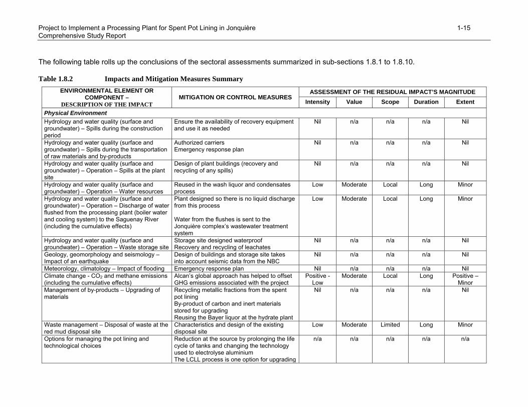
Project to Implement a Processing Plant for Spent Pot Lining in Jonquière 1-15 Comprehensive Study Report
The following table rolls up the conclusions of the sectoral assessments summarized in sub-sections 1.8.1 to 1.8.10. Table 1.8.2 Impacts and Mitigation Measures Summary
ASSESSMENT OF THE RESIDUAL IMPACT’S MAGNITUDE ENVIRONMENTAL ELEMENT OR COMPONENT –
DESCRIPTION OF THE IMPACT MITIGATION OR CONTROL MEASURES
Intensity Value Scope Duration Extent
Physical Environment Hydrology and water quality (surface and groundwater) – Spills during the construction period
Ensure the availability of recovery equipment and use it as needed
Nil n/a n/a n/a Nil
Hydrology and water quality (surface and groundwater) – Spills during the transportation of raw materials and by-products
Authorized carriers Emergency response plan
Nil n/a n/a n/a Nil
Hydrology and water quality (surface and groundwater) – Operation – Spills at the plant site
Design of plant buildings (recovery and recycling of any spills)
Nil n/a n/a n/a Nil
Hydrology and water quality (surface and groundwater) – Operation – Water resources
Reused in the wash liquor and condensates process
Low Moderate Local Long Minor
Hydrology and water quality (surface and groundwater) – Operation – Discharge of water flushed from the processing plant (boiler water and cooling system) to the Saguenay River (including the cumulative effects)
Plant designed so there is no liquid discharge from this process Water from the flushes is sent to the Jonquière complex’s wastewater treatment system
Low Moderate Local Long Minor
Hydrology and water quality (surface and groundwater) – Operation – Waste storage site
Storage site designed waterproof Recovery and recycling of leachates
Nil n/a n/a n/a Nil
Geology, geomorphology and seismology – Impact of an earthquake
Design of buildings and storage site takes into account seismic data from the NBC
Nil n/a n/a n/a Nil
Meteorology, climatology – Impact of flooding Emergency response plan Nil n/a n/a n/a Nil Climate change - CO2 and methane emissions (including the cumulative effects)
Alcan’s global approach has helped to offset GHG emissions associated with the project
Positive - Low
Moderate Local Long Positive – Minor
Management of by-products – Upgrading of materials
Recycling metallic fractions from the spent pot lining By-product of carbon and inert materials stored for upgrading Reusing the Bayer liquor at the hydrate plant
Nil n/a n/a n/a Nil
Waste management – Disposal of waste at the red mud disposal site
Characteristics and design of the existing disposal site
Low Moderate Limited Long Minor
Options for managing the pot lining and technological choices
Reduction at the source by prolonging the life cycle of tanks and changing the technology used to electrolyse aluminium The LCLL process is one option for upgrading
n/a n/a n/a n/a n/a

Project to Implement a Processing Plant for Spent Pot Lining in Jonquière 1-16 Comprehensive Study Report
ASSESSMENT OF THE RESIDUAL IMPACT’S MAGNITUDE ENVIRONMENTAL ELEMENT OR COMPONENT –
DESCRIPTION OF THE IMPACT MITIGATION OR CONTROL MEASURES
Intensity Value Scope Duration Extent the pot lining (recovering the chemical and calorific value) Characteristics of the by-products ensures strong potential for upgrading The LCLL process is based on known processes and techniques
Noise related to operating the plant and transportation: an increase varying from nil to 0.1 dBA
None Nil n/a n/a n/a Nil
Noise related to transporting waste to the disposal site: no increase
None Nil n/a n/a n/a Nil
Change in air quality as a result of dust emissions during construction
Spreading dust depressants as needed Low Moderate Local Short Minor
Air quality during plant operation Emission of suspended particulates, ammonia, SO2, CO, NO2 (including the cumulative effects)
Installation of dust extractors and staged mixing burners included in the plant’s design Installation of an incinerator to reduce ammonia emissions
Nil to low Moderate Local Long Minor
Odours (potentially associated with ammonia emissions)
Installation of an incinerator to reduce ammonia emissions
Nil n/a n/a n/a Nil
Biological Environment Loss of habitat – No habitats will be disturbed by the project
Site selected inside the industrial facility Nil n/a n/a n/a Nil
Vegetation – No natural areas will be disturbed by the project
Site selected inside the industrial facility Nil n/a n/a n/a Nil
Species at risk or species of special status and their habitat – No impact
None Nil n/a n/a n/a Nil
Fish and fish habitat – No impact Reused in the wash liquor and condensates process (no liquid discharges from the process)
Nil n/a n/a n/a Nil
Fauna and wildlife habitats (including migratory birds) – No impact
None Nil n/a n/a n/a Nil
Human Environment Health and safety of workers Design of various plant components
Risk analysis specific to work environment Training Individual protective equipment
n/a n/a n/a n/a n/a
Public health – No impact expected since the project has very little effect on the levels of fine particulates found in ambient air and given the trend towards improved air quality in the study area
Dust extractors Nil n/a n/a n/a Nil

Project to Implement a Processing Plant for Spent Pot Lining in Jonquière 1-17 Comprehensive Study Report
ASSESSMENT OF THE RESIDUAL IMPACT’S MAGNITUDE ENVIRONMENTAL ELEMENT OR COMPONENT –
DESCRIPTION OF THE IMPACT MITIGATION OR CONTROL MEASURES
Intensity Value Scope Duration Extent Public safety – The worst-case scenarios do not result in any impact for the public
Design of various plant components Safety measures Emergency response plan
Nil n/a n/a n/a Minor
Aesthetics and Landscape Site selected inside the Jonquière complex Nil n/a n/a n/a Nil Local population and neighbourhood Psychosocial impact: fear associated with the presence of a hazardous material
Alcan’s information and consultation activities Low Moderate Local Long Minor
Transportation and traffic
None Low Moderate Local Long Minor
Use of the land and resources for traditional purposes – No impact
None Nil n/a n/a n/a Nil
Economic spinoffs and jobs related to the construction and operating activities
Invitations from Alcan’s directory of construction contractors. At a competitive cost, regional companies will be favoured
n/a n/a n/a Positive impact
Heritage, cultural, historical, archaeological and paleontological resources – No impact
None Nil n/a n/a n/a Nil

Project to Implement a Processing Plant for Spent Pot Lining in Jonquière 1-18 Comprehensive Study Report
1.9 Monitoring and Follow-Up Program
A monitoring program will be established to ensure that all the specified control measures are applied and that standards and requirements are respected for each of the plant’s sources of atmospheric emissions. Liquid discharges (flushes) from the pot lining processing plant and surface runoff waters from the site will be directed to the Jonquière complex’s wastewater treatment system (Outfall Sewer B). This discharge point is already subject to regular monitoring. Once operations begin at the plant, all the solid waste to be sent for burial - iron oxides (produced during cyanide disposal) and descaling residues - will be characterized according to the Regulation respecting hazardous materials (Q-2, r.15.2). The waste storage site will be subject to a monitoring program that covers both the construction and operations. This program will specifically target quality control of materials (fill, geomembrane, drains) and include regular site inspections. Observation wells will be installed on the periphery of the storage cell in order to track groundwater during the storage period. The noise environment will be checked to verify the accuracy of forecasts made during the impact assessment. This campaign could be conducted at the eight test points where noise surveys were done during the impact assessment.
Project to Implement a Processing Plant for Spent Pot Lining in Jonquière 2-1 Comprehensive Study Report
2 INTRODUCTION
Aluminium producers have been faced with the problem of managing spent pot lining for several years now. Spent pot lining (SPL) is a by-product of primary aluminium production. Pot lining is the protective coating of the electrolytic cells used in aluminium smelters. This coating consists of carbon blocks from the cathode and refractory bricks. At the end of the cell’s operational life, its interior coating - the spent pot lining - must be removed. Since 1997, SPL has been classified as a hazardous material under Quebec’s Regulation respecting hazardous materials (Q-2, r.15.2), because of its composition and reactivity. The proponent, Alcan Primary Metal Group, proposes constructing and operating a SPL processing plant with an annual capacity of 80,000 tons at the site of the Jonquière complex in Saguenay. The plant will use a treatment process developed by Alcan, called "Low Concentration Caustic Leaching and Liming" (LCLL). Following several years of research, which included pilot tests, Alcan researchers developed the LCLL process, which is a hydrometallurgical process that enables the company to process pot lining in order to convert it into a non-hazardous waste and that facilitates the recycling and upgrading of some products derived from this treatment. Alcan Primary Metal Group submitted a funding request to Technology Partnerships Canada (an agency of Industry Canada) for its project to implement a processing plant for spent pot lining. Consequently, the project is subject to the federal environmental assessment process under the Canadian Environmental Assessment Act. This document presents the comprehensive environmental impact study of the proponent’s project, in order to meet the requirements of the Canadian Environmental Assessment Act and section 32 of the Comprehensive Study List Regulations2. This document was developed from the environmental impact assessment conducted in 2001 based on the requirements of Quebec’s Ministère de l’environnement. This document was prepared to meet the specific requirements outlined in the federal legislation’s Scoping Document. This assessment is intended to address all the various points enumerated in the project’s Environmental Assessment Scoping Document.
2. The proposed construction, decommissioning or abandonment of a facility used exclusively for the treatment,
incineration, disposal or recycling of hazardous waste, or an expansion of such a facility that would result in an increase in its production capacity of more than 35 per cent.

Project to Implement a Processing Plant for Spent Pot Lining in Jonquière 3-1 Comprehensive Study Report
3 PROJECT DESCRIPTION
3.1 Description of the Processing Plant’s Technical Features
3.1.1 Development and Construction Activities
3.1.1.1 Construction Work
The site selected for the construction of a SPL processing plant is located inside the Jonquière complex in the area currently occupied by Building 311 (refer to the illustration of the Jonquière complex in Appendix A), which was previously used for the storage of bauxite. This site is located in an area managed by the Vaudreuil plant, which is a large producer of various chemical products, such as metallurgical alumina, commercial alumina, hydrates and fluorine-based products. The property’s dimensions are 183 metres by 45 metres, for a total surface area of 8,235 square metres. The property is bordered to the northeast by railroads and to the southwest by Building 308, which is currently being used for the bulk storage of SPL before it can be sent to the long-term storage site3, by Building 309, which is used to store bauxite, and by Building 304, which is used to store alumina and chemical products in bags. To the south, Building 310 houses office space and the crushing facilities. The first phase of the construction work will consist of demolishing Building 311 and preparing the land. The demolition material will be sent to an authorized site, as specified in Alcan’s internal procedures; all of the work will be conducted so as to minimize the amount of dust generated at the site. The soil characterization work at the selected site was done in June 2005, and the results showed the soil is not contaminated. Concentrations obtained for all the analyzed parameters (PAH, heavy metals, cyanides, fluorides, C10- C50) were lower than the C criteria established in the Soil Protection and Rehabilitation of Contaminated Sites Policy from Quebec’s Ministère de l’environnement (MENV, 1999); most of the results were lower than the A or B criteria. The soil that needs to be excavated for the construction work will not require any specific treatment. The soil can be used as backfill at the site or be sent to the industrial waste disposal site (IWDS) at the Jonquière complex. Once site preparation is complete, the landfill infrastructures and building foundation piles will be installed. The next step will be construction of the foundations, followed by erection of the steel structures for the buildings. The SPL processing plant will include the following buildings (refer to the Overall Plan in Appendix B): a storage building for pot lining containers;
a building for the crushing process, including storage silos for the crushed pot lining;
a building for the LCLL process (a wet process); this building will contain all the leaching circuits, filtration, cyanide destruction, evaporation, and crystallization equipment. It will also
3 Note, as mentioned in section 3.1.2.2, that the pot lining to be treated in the new plant will arrive at the site in
special containers that will be stored in a new building, the construction of which is included in the project.
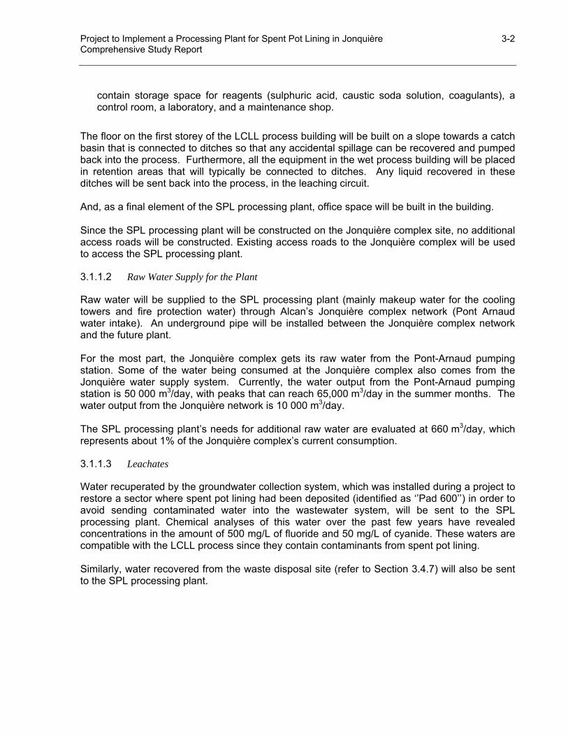
Project to Implement a Processing Plant for Spent Pot Lining in Jonquière 3-2 Comprehensive Study Report
contain storage space for reagents (sulphuric acid, caustic soda solution, coagulants), a control room, a laboratory, and a maintenance shop.
The floor on the first storey of the LCLL process building will be built on a slope towards a catch basin that is connected to ditches so that any accidental spillage can be recovered and pumped back into the process. Furthermore, all the equipment in the wet process building will be placed in retention areas that will typically be connected to ditches. Any liquid recovered in these ditches will be sent back into the process, in the leaching circuit. And, as a final element of the SPL processing plant, office space will be built in the building. Since the SPL processing plant will be constructed on the Jonquière complex site, no additional access roads will be constructed. Existing access roads to the Jonquière complex will be used to access the SPL processing plant.
3.1.1.2 Raw Water Supply for the Plant
Raw water will be supplied to the SPL processing plant (mainly makeup water for the cooling towers and fire protection water) through Alcan’s Jonquière complex network (Pont Arnaud water intake). An underground pipe will be installed between the Jonquière complex network and the future plant. For the most part, the Jonquière complex gets its raw water from the Pont-Arnaud pumping station. Some of the water being consumed at the Jonquière complex also comes from the Jonquière water supply system. Currently, the water output from the Pont-Arnaud pumping station is 50 000 m3/day, with peaks that can reach 65,000 m3/day in the summer months. The water output from the Jonquière network is 10 000 m3/day. The SPL processing plant’s needs for additional raw water are evaluated at 660 m3/day, which represents about 1% of the Jonquière complex’s current consumption.
3.1.1.3 Leachates
Water recuperated by the groundwater collection system, which was installed during a project to restore a sector where spent pot lining had been deposited (identified as ‘’Pad 600’’) in order to avoid sending contaminated water into the wastewater system, will be sent to the SPL processing plant. Chemical analyses of this water over the past few years have revealed concentrations in the amount of 500 mg/L of fluoride and 50 mg/L of cyanide. These waters are compatible with the LCLL process since they contain contaminants from spent pot lining. Similarly, water recovered from the waste disposal site (refer to Section 3.4.7) will also be sent to the SPL processing plant.

Project to Implement a Processing Plant for Spent Pot Lining in Jonquière 3-3 Comprehensive Study Report
3.1.1.4 Natural Gas Supply
An underground pipeline to supply natural gas will be installed between the Jonquière complex network and the future plant. Natural gas will be used to fuel the buildings’ heating units and for the hot water tank’s exhaust gas incinerator. Building 425, which will house the new vapour-producing boiler, already has a natural gas supply.
3.1.1.5 Electrical Supply
Electrical energy used to fuel the plant will come from Alcan’s network. Two on-site transformers will reduce the voltage to 600 V. A diesel-powered emergency generator will power essential equipment in the case of a power outage.
3.1.1.6 Vapour Supply
The vapour needed for the process will be produced by an existing electrical boiler that will be reactivated for the SPL processing plant project. All the vapour produced will be sent through a pipe to the SPL processing plant. In cases where the vapour will be used through indirect contact, either in heat exchangers or in tank coils, the condensate will be recovered and returned to the boiler to produce vapour. The rest of the vapour is used directly in the process and gets added to the SPL processing plant’s water resources.
3.1.1.7 Schedule
Construction work on the plant is expected to begin during the third quarter (Q3) of 2005 and be carried out over a period of approximately 20 months. The demonstration phase of the SPL processing plant should begin during the second quarter (Q2) of 2008.
3.1.2 Operational Activities at the Plant
This section summarizes the process for which Alcan is requesting a Certificate of Authorization. Figure 3.1.1 is a schematic diagram of the LCLL process as it will be set up and Figure 3.1.2 is a services diagram. The atmospheric discharge points and the solid waste being generated are identified on the diagram.
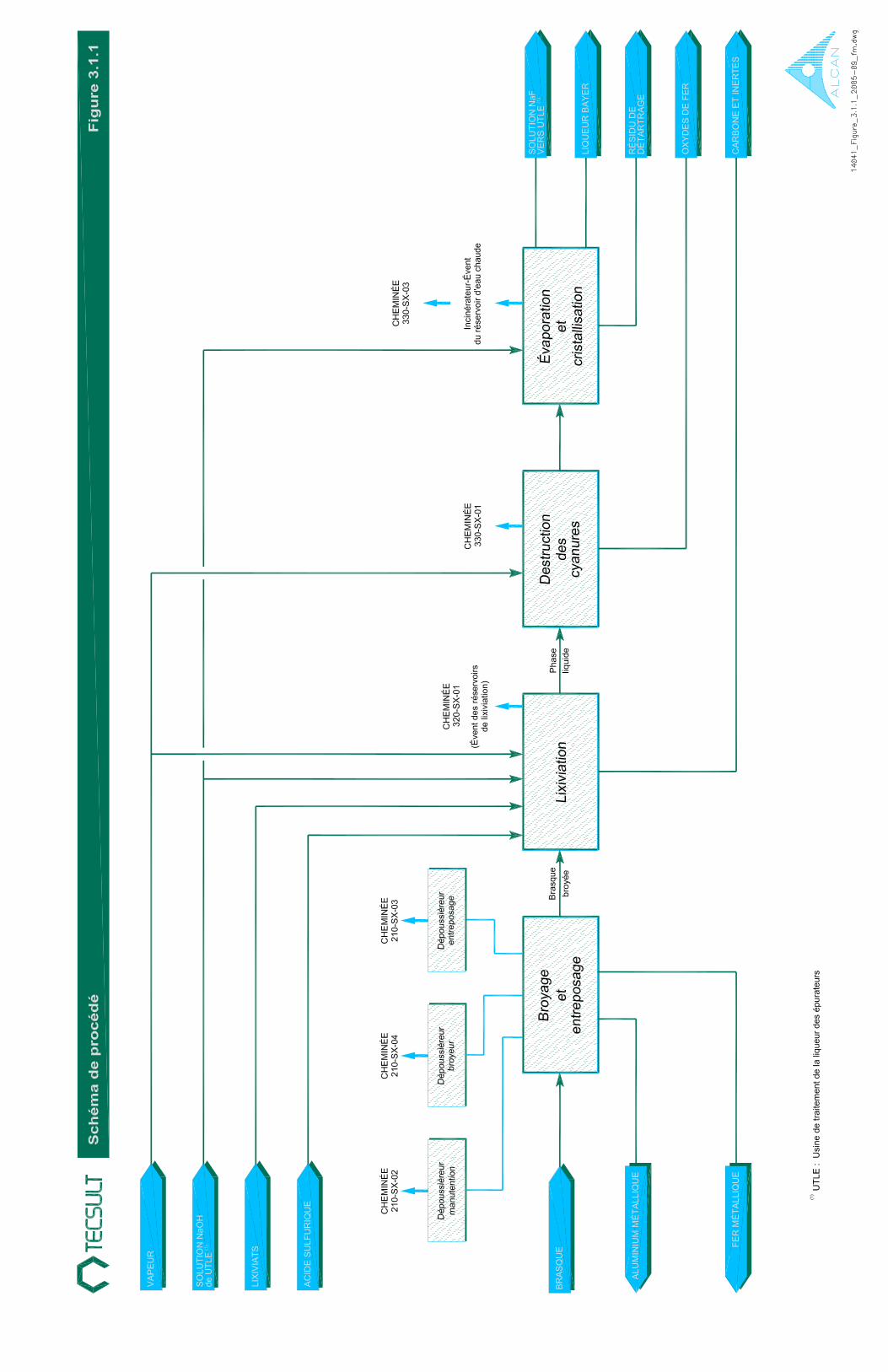

Project to Implement a Processing Plant for Spent Pot Lining in Jonquière 3-5 Comprehensive Study Report
3.1.1 Correspondence Table
Vapeur Vapour Solution NaOH de UTLE (1) NaOH solution from the SLPP (1) Lixiviats Leachates Acide sulfurique Sulfuric acid Cheminée 210-SX-02 Chimney 210-SX-02 Dépoussiéreur manutention Dust extractor – Handling Cheminée 210-SX-04 Chimney 210-SX-04 Dépoussiéreur broyeur Dust extractor – Crusher Cheminée 210-SX-03 Chimney 210-SX-03 Dépoussiéreur entreposage Dust extractor – Storage Cheminée 320-SX-01 Chimney 320-SX-01 Évent des réservoirs de lixiviation Release vent of the leachate tanks Cheminée 330-SX-01 Chimney 330-SX-01 Cheminée 330-SX-03 Chimney 330-SX-03 Incinérateur – Évent du réservoir d’eau chaude
Incinerator – Release vent of the hot water tank
Brasque Pot lining Aluminium métallique Metallic aluminum Fer métallique Metallic iron Broyage et entreposage Crushing and storage Brasque broyée Crushed pot lining Lixiviation Leaching Phase liquide Liquid phase Destruction des cyanures Cyanide destruction Évaporation et cristallisation Evaporation and crystallization Solution NaF vers UTLE (1) NaF solution to the SLPP (1) Liqueur Bayer Bayer Liquor Résidu de détartrage Descaling residues Oxydes de fer Iron oxides Carbone et inertes Carbon and inert materials (1) UTLE : Usine de traitement de la liqueur des épurateurs
(1) SLPP: Scrubber Liquor Processing Plant

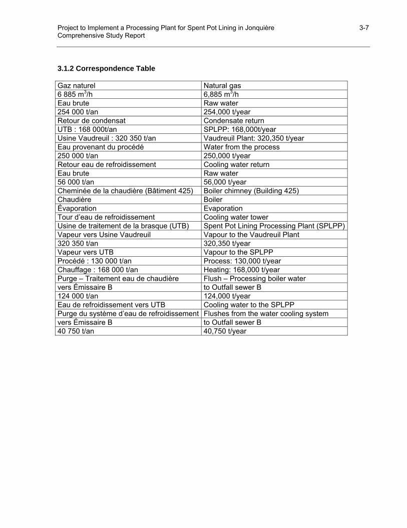
Project to Implement a Processing Plant for Spent Pot Lining in Jonquière 3-7 Comprehensive Study Report
3.1.2 Correspondence Table Gaz naturel Natural gas 6 885 m3/h 6,885 m3/h Eau brute Raw water 254 000 t/an 254,000 t/year Retour de condensat Condensate return UTB : 168 000t/an SPLPP: 168,000t/year Usine Vaudreuil : 320 350 t/an Vaudreuil Plant: 320,350 t/year Eau provenant du procédé Water from the process 250 000 t/an 250,000 t/year Retour eau de refroidissement Cooling water return Eau brute Raw water 56 000 t/an 56,000 t/year Cheminée de la chaudière (Bâtiment 425) Boiler chimney (Building 425) Chaudière Boiler Évaporation Evaporation Tour d’eau de refroidissement Cooling water tower Usine de traitement de la brasque (UTB) Spent Pot Lining Processing Plant (SPLPP)Vapeur vers Usine Vaudreuil Vapour to the Vaudreuil Plant 320 350 t/an 320,350 t/year Vapeur vers UTB Vapour to the SPLPP Procédé : 130 000 t/an Process: 130,000 t/year Chauffage : 168 000 t/an Heating: 168,000 t/year Purge – Traitement eau de chaudière Flush – Processing boiler water vers Émissaire B to Outfall sewer B 124 000 t/an 124,000 t/year Eau de refroidissement vers UTB Cooling water to the SPLPP Purge du système d’eau de refroidissement Flushes from the water cooling system vers Émissaire B to Outfall sewer B 40 750 t/an 40,750 t/year
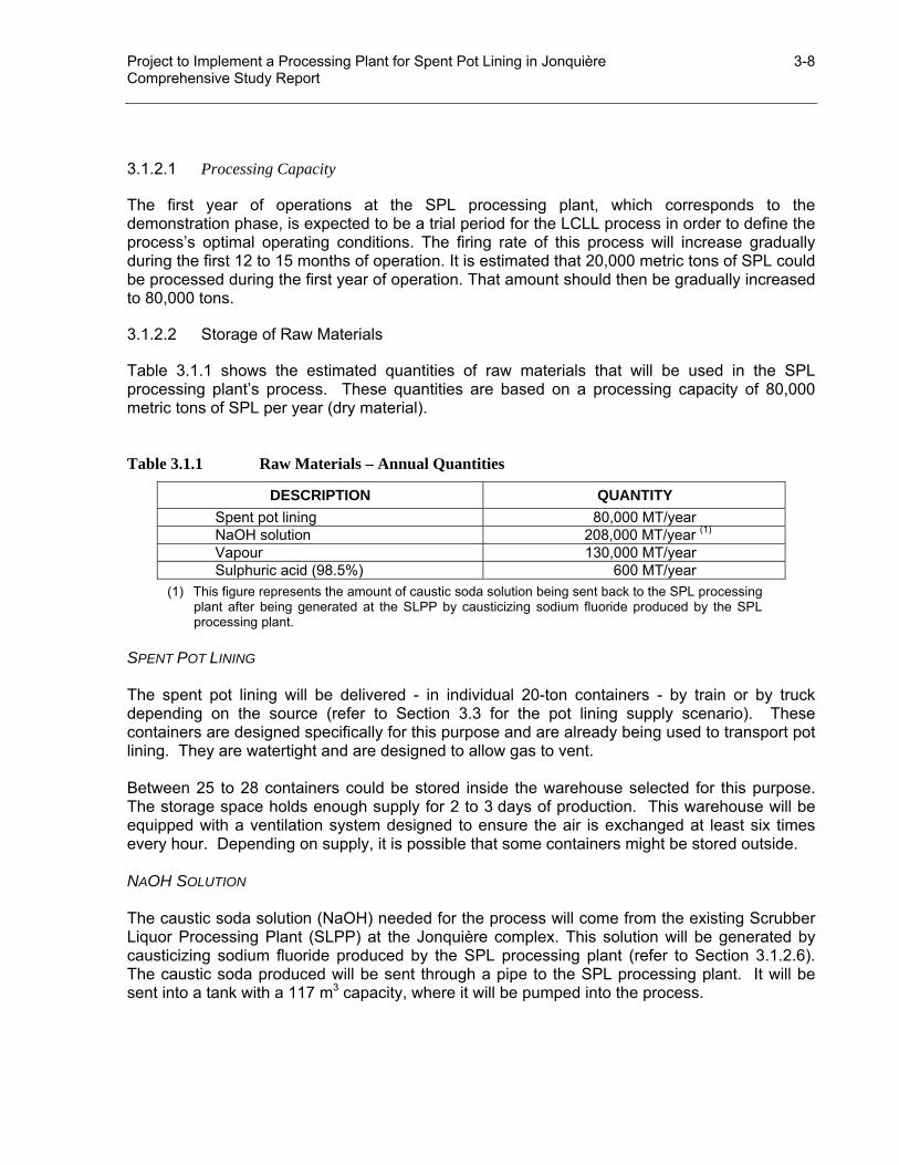
Project to Implement a Processing Plant for Spent Pot Lining in Jonquière 3-8 Comprehensive Study Report
3.1.2.1 Processing Capacity
The first year of operations at the SPL processing plant, which corresponds to the demonstration phase, is expected to be a trial period for the LCLL process in order to define the process’s optimal operating conditions. The firing rate of this process will increase gradually during the first 12 to 15 months of operation. It is estimated that 20,000 metric tons of SPL could be processed during the first year of operation. That amount should then be gradually increased to 80,000 tons.
3.1.2.2 Storage of Raw Materials
Table 3.1.1 shows the estimated quantities of raw materials that will be used in the SPL processing plant’s process. These quantities are based on a processing capacity of 80,000 metric tons of SPL per year (dry material). Table 3.1.1 Raw Materials – Annual Quantities
DESCRIPTION QUANTITY Spent pot lining 80,000 MT/year NaOH solution 208,000 MT/year (1) Vapour 130,000 MT/year Sulphuric acid (98.5%) 600 MT/year
(1) This figure represents the amount of caustic soda solution being sent back to the SPL processing plant after being generated at the SLPP by causticizing sodium fluoride produced by the SPL processing plant.
SPENT POT LINING The spent pot lining will be delivered - in individual 20-ton containers - by train or by truck depending on the source (refer to Section 3.3 for the pot lining supply scenario). These containers are designed specifically for this purpose and are already being used to transport pot lining. They are watertight and are designed to allow gas to vent. Between 25 to 28 containers could be stored inside the warehouse selected for this purpose. The storage space holds enough supply for 2 to 3 days of production. This warehouse will be equipped with a ventilation system designed to ensure the air is exchanged at least six times every hour. Depending on supply, it is possible that some containers might be stored outside. NAOH SOLUTION The caustic soda solution (NaOH) needed for the process will come from the existing Scrubber Liquor Processing Plant (SLPP) at the Jonquière complex. This solution will be generated by causticizing sodium fluoride produced by the SPL processing plant (refer to Section 3.1.2.6). The caustic soda produced will be sent through a pipe to the SPL processing plant. It will be sent into a tank with a 117 m3 capacity, where it will be pumped into the process.

Project to Implement a Processing Plant for Spent Pot Lining in Jonquière 3-9 Comprehensive Study Report
SULPHURIC ACID Tests results showed that a certain amount of fluorides and cyanides might remain in the solid phase after the caustic soda leaching step. The next step, in order to recover these fluorides and cyanides, is an activation wash where sulphuric acid is added to lower the pH. The sulphuric acid used at the plant will come from the Jonquière complex’s sulphuric acid distribution network. The concentrated sulphuric acid will be stored in a tank with a 10 m3 capacity. The diluted sulphuric acid (10%) will be stored in a tank with a 10 m3 capacity. Each of these tanks will be placed in a containment area that can hold 110% of their capacity. COAGULANTS Two coagulating agents, which will be received in a dry format, will be stored in bags. During the process, an aqueous solution of coagulants will be prepared and added to the various solutions in order to increase filtering efficiency.
3.1.2.3 Crushing
The pot lining containers will be transported by fork truck from the storage building. They will be weighed and emptied directly into an input chute supplying a closed conveyor that sends the pot lining into the crusher. According to plans, the pot lining received at the processing plant will be smaller in size than 30 cm and will not contain any large metallic pieces. The purpose of this crusher is to obtain a product that is easier to handle and to facilitate homogenization and the mixing of pot lining from various sources, and, in so doing, to reduce variations in the composition of pot lining being fed into the process. The crusher’s input conveyor will be equipped with a pulley that has a magnetic head to retrieve ferrous material. These materials will then pass through an electromagnetic separator. This separator will separate and recover the metals (aluminium and iron), which will be stored in portable containers. The aluminium will be sent to the aluminium smelter, while the iron will be sold for recovery. A dust extractor will capture any dust generated during the unloading process and while feeding the crusher (source No. 14). The crushed material will be sifted and sent to the storage silos by way of an air-powered conveyor system. A dust extractor will capture any dust generated during the crushing process (source No. 2). A ventilation system will be installed on the crushed pot lining storage silos in order to vent the air used to transport the pot lining and to ensure that any gas released from the crush pot lining is not confined in the silos. This system will be equipped with a dust extractor (source No. 3). The fans from the three ventilation systems in the crushing and storage sector will be connected to the emergency power supply system in case of a power failure. Backup fans that are big enough to ensure the venting of generated gases will also be provided in case the main fans break down. 4 The numbering of discharge points refers to Table 3.2.2, where the main characteristics of each discharge point
are listed.

Project to Implement a Processing Plant for Spent Pot Lining in Jonquière 3-10 Comprehensive Study Report
The pot lining crushing and storage building will be designed so as to prevent possible contact between the pot lining and water; no water wash stations will be installed in this section of the plant and no water pipes will be installed near the crushing equipment and the storage silos.
3.1.2.4 Water and Caustic Leaching
The water leaching and caustic soda leaching operations will solubilize any fluorides and cyanides found in the SPL. By way of a screw auger conveyor, the pot lining will be sent to a second dry crusher from the storage silos in order to further reduce the size of the pot lining particulates for the leaching process. Dust generated during this crushing process is captured in fume hoods and sent to the storage space’s ventilation system (source No. 3). The crushed pot lining will be gathered in a hopper and sent by way of a screw auger conveyor to a tank where water will be added. This mix will be gravity fed into the water-leaching tank. The water-leaching tank will be heated using a vapour coil in order to increase the temperature and thus facilitate dissolution of the fluorides and cyanides. The solution obtained through the water leaching process will then be filtered. The filtrate will be sent to a storage tank, whereas the filter cake will be emptied into the caustic soda leaching tanks and a weak caustic solution will be added. The caustic soda leaching tank will also be heated using a vapour coil. Once the caustic soda leaching process is complete, the mixture is then filtered. The filtrate, which contains fluorides, cyanides, caustic soda and aluminium in the form of a solution will be sent to a storage tank. The filter cake will be sent to the activation wash. The activation wash is designed to process some pot lining (i.e. pot lining from the Söderberg cells that use lithium) in order to remove the residual bit of fluorides and cyanides that were not dissolved during the water and caustic soda leaching processes. The solids will be mixed with vapour and sulphuric acid to lower the pH to about 8. Once the activation wash is complete, the mixture will be filtered. The filtrate will be sent for evaporation and the filter cake will be sent to the polishing wash tank. The purpose of the polishing wash is to remove the remaining fluoride and cyanide following the activation wash. The solids will be mixed with vapour and caustic soda. The mixture will then be filtered; the filtrate will be sent back to the tank containing the caustic soda solution, so that it can be reused in the caustic soda leaching process. The filter cake, which is composed of inert materials (carbon and refractory), will be placed in containers for transport to the warehouse. The inert materials will be verified to ensure they meet the standards and do not present any characteristics of a hazardous material, as defined in the Regulation respecting hazardous materials (Q-2, r.15.2). If this is not the case, these inert materials will be sent back to the water leaching and caustic soda leaching circuits. Tanks used for the water leaching process, the caustic soda leaching process, the activation wash, and the polishing wash will be closed. A sweeping gas (nitrogen or air) will be used to exhaust the gas generated by the reactions in each of these tanks. These gases will be aspirated by the leaching gas exhaust system (source No. 4), which will keep all the tanks under a slight negative pressure.
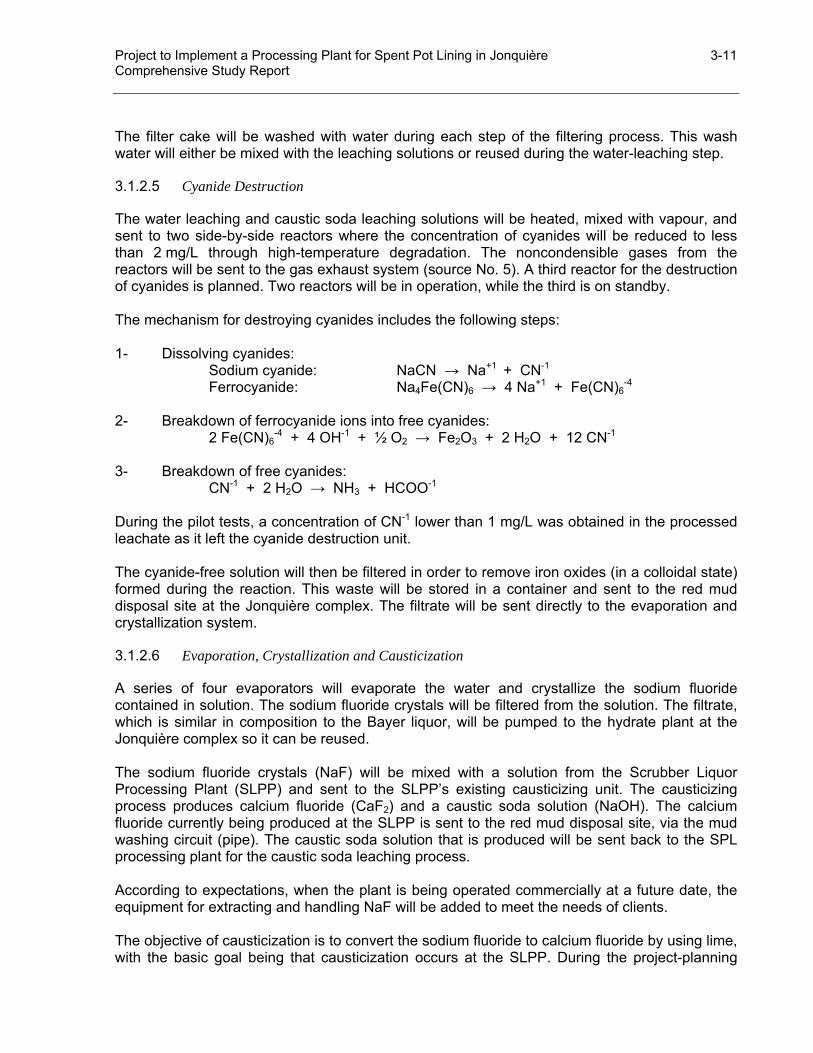
Project to Implement a Processing Plant for Spent Pot Lining in Jonquière 3-11 Comprehensive Study Report
The filter cake will be washed with water during each step of the filtering process. This wash water will either be mixed with the leaching solutions or reused during the water-leaching step.
3.1.2.5 Cyanide Destruction
The water leaching and caustic soda leaching solutions will be heated, mixed with vapour, and sent to two side-by-side reactors where the concentration of cyanides will be reduced to less than 2 mg/L through high-temperature degradation. The noncondensible gases from the reactors will be sent to the gas exhaust system (source No. 5). A third reactor for the destruction of cyanides is planned. Two reactors will be in operation, while the third is on standby. The mechanism for destroying cyanides includes the following steps: 1- Dissolving cyanides: Sodium cyanide: NaCN → Na+1 + CN-1
Ferrocyanide: Na4Fe(CN)6 → 4 Na+1 + Fe(CN)6-4
2- Breakdown of ferrocyanide ions into free cyanides: 2 Fe(CN)6
-4 + 4 OH-1 + ½ O2 → Fe2O3 + 2 H2O + 12 CN-1 3- Breakdown of free cyanides: CN-1 + 2 H2O → NH3 + HCOO-1 During the pilot tests, a concentration of CN-1 lower than 1 mg/L was obtained in the processed leachate as it left the cyanide destruction unit. The cyanide-free solution will then be filtered in order to remove iron oxides (in a colloidal state) formed during the reaction. This waste will be stored in a container and sent to the red mud disposal site at the Jonquière complex. The filtrate will be sent directly to the evaporation and crystallization system.
3.1.2.6 Evaporation, Crystallization and Causticization
A series of four evaporators will evaporate the water and crystallize the sodium fluoride contained in solution. The sodium fluoride crystals will be filtered from the solution. The filtrate, which is similar in composition to the Bayer liquor, will be pumped to the hydrate plant at the Jonquière complex so it can be reused. The sodium fluoride crystals (NaF) will be mixed with a solution from the Scrubber Liquor Processing Plant (SLPP) and sent to the SLPP’s existing causticizing unit. The causticizing process produces calcium fluoride (CaF2) and a caustic soda solution (NaOH). The calcium fluoride currently being produced at the SLPP is sent to the red mud disposal site, via the mud washing circuit (pipe). The caustic soda solution that is produced will be sent back to the SPL processing plant for the caustic soda leaching process. According to expectations, when the plant is being operated commercially at a future date, the equipment for extracting and handling NaF will be added to meet the needs of clients. The objective of causticization is to convert the sodium fluoride to calcium fluoride by using lime, with the basic goal being that causticization occurs at the SLPP. During the project-planning
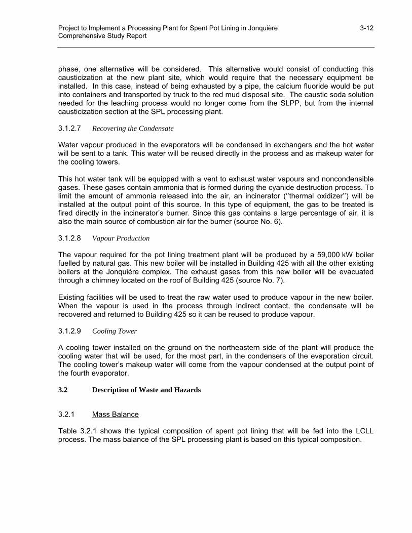
Project to Implement a Processing Plant for Spent Pot Lining in Jonquière 3-12 Comprehensive Study Report
phase, one alternative will be considered. This alternative would consist of conducting this causticization at the new plant site, which would require that the necessary equipment be installed. In this case, instead of being exhausted by a pipe, the calcium fluoride would be put into containers and transported by truck to the red mud disposal site. The caustic soda solution needed for the leaching process would no longer come from the SLPP, but from the internal causticization section at the SPL processing plant.
3.1.2.7 Recovering the Condensate
Water vapour produced in the evaporators will be condensed in exchangers and the hot water will be sent to a tank. This water will be reused directly in the process and as makeup water for the cooling towers. This hot water tank will be equipped with a vent to exhaust water vapours and noncondensible gases. These gases contain ammonia that is formed during the cyanide destruction process. To limit the amount of ammonia released into the air, an incinerator (‘’thermal oxidizer’’) will be installed at the output point of this source. In this type of equipment, the gas to be treated is fired directly in the incinerator’s burner. Since this gas contains a large percentage of air, it is also the main source of combustion air for the burner (source No. 6).
3.1.2.8 Vapour Production
The vapour required for the pot lining treatment plant will be produced by a 59,000 kW boiler fuelled by natural gas. This new boiler will be installed in Building 425 with all the other existing boilers at the Jonquière complex. The exhaust gases from this new boiler will be evacuated through a chimney located on the roof of Building 425 (source No. 7). Existing facilities will be used to treat the raw water used to produce vapour in the new boiler. When the vapour is used in the process through indirect contact, the condensate will be recovered and returned to Building 425 so it can be reused to produce vapour.
3.1.2.9 Cooling Tower
A cooling tower installed on the ground on the northeastern side of the plant will produce the cooling water that will be used, for the most part, in the condensers of the evaporation circuit. The cooling tower’s makeup water will come from the vapour condensed at the output point of the fourth evaporator.
3.2 Description of Waste and Hazards
3.2.1 Mass Balance
Table 3.2.1 shows the typical composition of spent pot lining that will be fed into the LCLL process. The mass balance of the SPL processing plant is based on this typical composition.
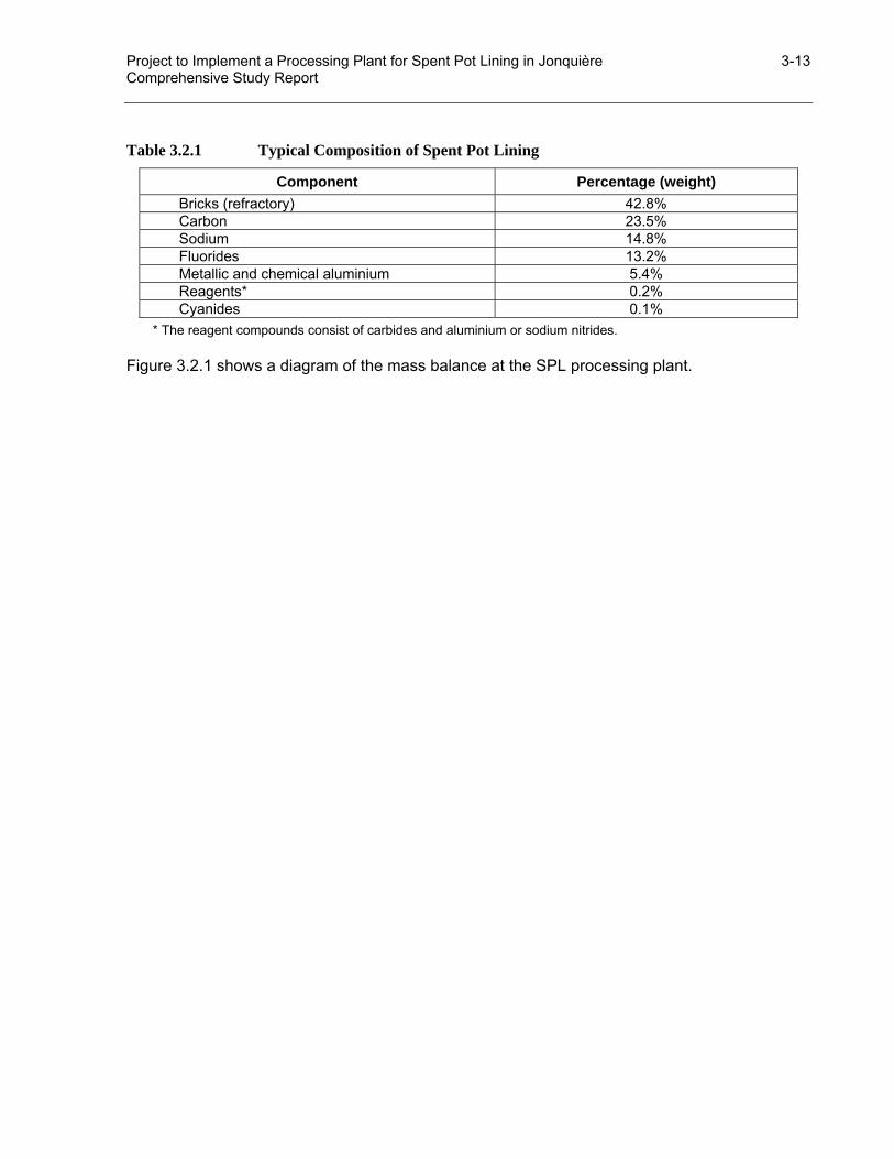
Project to Implement a Processing Plant for Spent Pot Lining in Jonquière 3-13 Comprehensive Study Report
Table 3.2.1 Typical Composition of Spent Pot Lining
Component Percentage (weight) Bricks (refractory) 42.8% Carbon 23.5% Sodium 14.8% Fluorides 13.2% Metallic and chemical aluminium 5.4% Reagents* 0.2% Cyanides 0.1%
* The reagent compounds consist of carbides and aluminium or sodium nitrides. Figure 3.2.1 shows a diagram of the mass balance at the SPL processing plant.

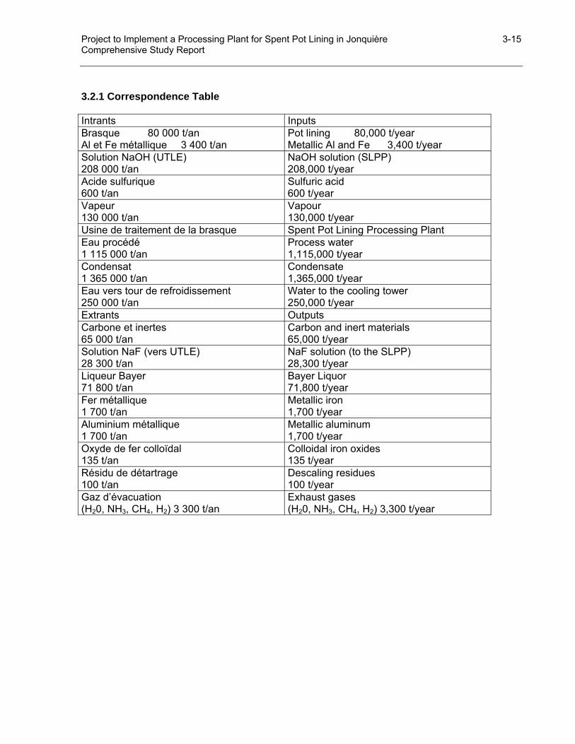
Project to Implement a Processing Plant for Spent Pot Lining in Jonquière 3-15 Comprehensive Study Report
3.2.1 Correspondence Table Intrants Inputs Brasque 80 000 t/an Al et Fe métallique 3 400 t/an
Pot lining 80,000 t/year Metallic Al and Fe 3,400 t/year
Solution NaOH (UTLE) 208 000 t/an
NaOH solution (SLPP) 208,000 t/year
Acide sulfurique 600 t/an
Sulfuric acid 600 t/year
Vapeur 130 000 t/an
Vapour 130,000 t/year
Usine de traitement de la brasque Spent Pot Lining Processing Plant Eau procédé 1 115 000 t/an
Process water 1,115,000 t/year
Condensat 1 365 000 t/an
Condensate 1,365,000 t/year
Eau vers tour de refroidissement 250 000 t/an
Water to the cooling tower 250,000 t/year
Extrants Outputs Carbone et inertes 65 000 t/an
Carbon and inert materials 65,000 t/year
Solution NaF (vers UTLE) 28 300 t/an
NaF solution (to the SLPP) 28,300 t/year
Liqueur Bayer 71 800 t/an
Bayer Liquor 71,800 t/year
Fer métallique 1 700 t/an
Metallic iron 1,700 t/year
Aluminium métallique 1 700 t/an
Metallic aluminum 1,700 t/year
Oxyde de fer colloïdal 135 t/an
Colloidal iron oxides 135 t/year
Résidu de détartrage 100 t/an
Descaling residues 100 t/year
Gaz d’évacuation (H20, NH3, CH4, H2) 3 300 t/an
Exhaust gases (H20, NH3, CH4, H2) 3,300 t/year

Project to Implement a Processing Plant for Spent Pot Lining in Jonquière 3-16 Comprehensive Study Report
3.2.2 Air Emissions
3.2.2.1 Description
Table 3.2.2 enumerates the discharge points for air emissions and their characteristics. Table 3.2.2 Sources of Air Emissions – Conditions and Emission Rates
SOURCE Temperature(°C)
Output (Am3/h) Emission Rate
1 Dust extractor – Handling the pot lining Chimney 210-SX-02 20 67,960
(NH3): 0.159 kg/h CH4: 0.132 kg/h H2: 0.112 kg/h Part.: 0.136 kg/h
2 Dust extractor – Crushing the pot lining Chimney 210-SX-04 20 33,980
(NH3): 0.159 kg/h CH4: 0.132 kg/h H2: 0.112 Part.: 0.068 kg/h
3 Dust extractor – Crushed pot lining silos Chimney 210-SX-03 20 33,980
(NH3): 1.59 kg/h CH4: 1.32 kg/h H2: 1.12 Part.: 0.068 kg/h
4 Leaching gases (water and caustic) Chimney 320-SX-01 87 50,500
(NH3): 13.36 kg/h CH4: 11.1 kg/h H2: 9.39 kg/h
5 Noncondensible gases (cyanide destruction) Chimney 330-SX-01 180 100 (NH3): 0.24 kg/h
6 Hot water tank gas incinerator Chimney 380-SX-03 816 488 (NH3): 1.18 kg/h
7 Boiler combustion gas 200 131,200
CO: 13.2 kg/h NOx: 3.6 kg/h SOx: 0.087 kg/h Part.: 0.88 kg/h
8 Roof-top ventilation fans – Crushing sector (4 in total) 20 27,180 each Part.: 0.0275 kg/h
(by source)
9 Roof-top ventilation fans – Leaching sector (6 in total) 20 27,180 each Part.: 0.013 kg/h
(by source) PARTICULATES The particulates emission rate from the dust extractors at sources 1, 2 and 3 are estimations, based on the following assumptions: the concentration of particulates in the gases at the dust extractor intake is 20 g/m3;
the dust extractors are 99.99%5 efficient in removing the particulates. A dust extractor (source No. 1) will help control the dust emissions generated by the handling of SPL right up to the crushing stage.
5 The efficiency of dust extractors in removing particulates was established by the engineering firm, after verifying
with potential suppliers. This requirement is included in the current specifications of the invitation to tender process.

Project to Implement a Processing Plant for Spent Pot Lining in Jonquière 3-17 Comprehensive Study Report
A second dust extractor (source No. 2) will capture any dust generated during the crushing process. The crushed pot lining storage silos will be ventilated to ensure that the concentration of gases that might be released during storage is maintained at a low level. Air from the silos will be sent to a dust extractor (source No. 3). Dust generated during the second step of the crushing process, before leaching, will also be sent to this dust extractor. The dust recovered in all the dust extractors will be sent to the feed hopper of the water-leaching tank. Rooftop ventilation fans are planned for the crushing building (4 fans, source No. 8) and for the leaching building (6 fans, source No. 9) to ensure a sufficient number of air exchanges and to maintain the quality of the work environment. The assessment of particulate emission rates from these fans is based on the assumption that the concentration of dust will be 1 mg/m3 in the crushing building and 500 µg/m3 in the leaching building. Since the dust captured by the dust extractors will have been produced during the handling and crushing of the SPL, the dust recovered from the dust extractors is expected to have a composition similar to that of SPL. AMMONIA Dust extractors The dust extractors will help to control dust emissions generated during the handling and crushing of SPL. Although measures have been anticipated at this step in the process to minimize contact between humidity and the pot lining, ammonia (NH3) could be generated during these operations at each of these sources. The generation rates of gas produced by the pot lining when it comes into contact with water were used to estimate the ammonia emission rates. These rates were used to design the ventilation systems and were established using internal Alcan data; the rates are considered to be overstated, since the gas composition was considered to be identical to that of gas generated by leaching in the LCLL process. In the case of crushed pot lining, a higher gas generation rate was used to account for the fact that freshly crushed pot lining has a larger surface exposed to air and can thus generate more gas than the pot lining received at the processing plant. The dust extractors (sources No. 1 and No. 2) will help to control dust emissions generated during the handling and crushing of SPL. A maximum rate of 0.159 kg/h of ammonia (NH3) could be generated during these operations at each of these sources. This assessment is based on a gas generation rate of 0.1 cm3 for every supplied gram of pot lining and on the assumption that the composition of gas generated would be the same as that generated during the leaching process. The air used to vent the crushed pot lining storage silos will be sent to a dust extractor (source No. 3). The maximum amount of ammonia that could be discharged from this source is estimated at 1.59 kg/h. In this case, this assessment is based on a gas generation rate of 1.0 cm3 per gram of pot lining being fed into the silos.
Project to Implement a Processing Plant for Spent Pot Lining in Jonquière 3-18 Comprehensive Study Report
Air flow rates from sources No. 1, 2 and 3 were established so as to ensure that outputs are sufficient to maintain the concentration of hydrogen at less than 10 times its minimum flammability concentration, which is 4% by volume in the air. Leaching During the water leaching and caustic soda leaching operations, the gases from the reactors will be drawn away by the ventilation system and released into the air (source No. 4). The amount of ammonia that could be released from this source is estimated at 13.36 kg/h. This estimation is based on the aggregate of chemical reactions that will be produced during the leaching process. Cyanide Destruction Ammonia will also be generated during the reaction that occurs when cyanides are destroyed at high temperatures. According to test results, an estimated 1% of the ammonia formed will be discharged in the noncondensible gases at the reactors’ vent (source No. 5). This quantity will amount to 0.24 kg/h. The rest of the ammonia formed during the cyanide destruction process will end up in the hot water tank. As described earlier, an incinerator (‘’thermal oxidizer’’) will be installed at the hot water tank’s release vent to limit the amount of ammonia released into the air (source No. 6). According to data from the preliminary engineering file, the preliminary design criteria for this incinerator are as follows:
• Gas flow rate (containing ammonia) at the incinerator’s intake: 100 m3/h at 60°C; • Amount of ammonia present in this gas: 23.6 kg/h; • Operational temperature of the incinerator: 816°C (1500°F); • Natural gas flow rate: 3.7 m3/h at the burner and 1.3 m3/h at the pilot; • Effectiveness in destroying the ammonia: 95%6.
COMBUSTION GAS Waste from source No. 7 is made of combustion gas from the vapour-producing boiler fuelled by natural gas that will be installed in Building 425 of the Jonquière complex. Concentrations of carbon monoxide (CO), nitrogen dioxide (NOx) and sulphur oxides (SOx) in the combustion gases of natural gas were established using data from combustion system suppliers.
6 The supplier, according to data obtained directly, would be able to guarantee destruction with 96% effectiveness.

Project to Implement a Processing Plant for Spent Pot Lining in Jonquière 3-19 Comprehensive Study Report
3.2.2.2 Respecting Discharge Standards
SOURCES OF COMBUSTION According to Quebec’s current Regulation respecting the quality of the atmosphere (Q-2, r.20), particulate emissions from the 59 MW boiler, which will be installed in Building 425 of the Jonquière complex to supply the vapour needed for the SPL processing plant, should be below 60 mg/MJ (60 g/GJ). The fuel used will be natural gas, which generates very few particulates during its combustion. The estimated quantity of particulates that will be discharged through the boiler’s chimney is 0.88 kg per hour. This amount represents an emission rate of 4.14 mg/MJ (4.14 g/GJ). In the draft Regulation amending the Regulation respecting the quality of the atmosphere (technical version of July 2002), the standard for nitrogen dioxide emissions is 40 g/GJ from the fuel for a natural gas combustion system that has a rated capacity of above 30 MW. Nitrogen dioxide emissions expected from the boilers will be 15 g/GJ. PARTICULATE EMISSIONS Based on section 24 of Quebec’s current Regulation respecting the quality of the atmosphere (Q-2, r.20), the maximum rate of particulate emissions has been established using the process’s firing rate. The process’s firing rate is determined using the total weight of material introduced into a process over a defined period of time. Since, in the case of the SPL processing plant, the particulate emissions will essentially be derived from the handling, crushing and storage of the SPL, and since we could consider all the operations carried out in the plant’s dry building a “process,” the firing rate of the process that needs to be considered is thus limited to the pot lining firing rate, which is 80,000 t/year (10.73 t/h). According to Schedule B of the Regulation respecting the quality of the atmosphere, the maximum rate of particulate emissions (E) in kg/h, for a new source, is established using the following equation, when the process weight rate is less than 25 tons per hour:
E = 1,7p0.62 where p represents the process weight rate in t/h. For a process weight rate of 10.73 t/h, the maximum particulate emission rate is 7.4 kg/h. The maximum particulate emissions rate is estimated at 1.34 kg/h when all the sources, including the boiler, are taken into consideration (refer to Table 3.2.3). Based on this estimation, the particulate emissions standard, under Quebec’s Regulation respecting the quality of the atmosphere, will be respected. Table 3.2.3 Particulate Discharges into the Air – Respecting Standards
Description Total Discharge (kg/h) Emission Standards (kg/h) Particulates 1.34 7.4
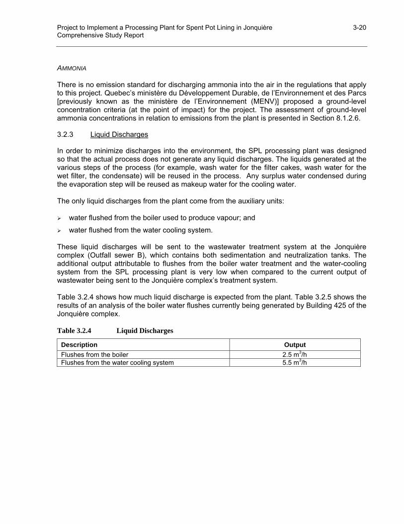
Project to Implement a Processing Plant for Spent Pot Lining in Jonquière 3-20 Comprehensive Study Report
AMMONIA There is no emission standard for discharging ammonia into the air in the regulations that apply to this project. Quebec’s ministère du Développement Durable, de l’Environnement et des Parcs [previously known as the ministère de l’Environnement (MENV)] proposed a ground-level concentration criteria (at the point of impact) for the project. The assessment of ground-level ammonia concentrations in relation to emissions from the plant is presented in Section 8.1.2.6.
3.2.3 Liquid Discharges
In order to minimize discharges into the environment, the SPL processing plant was designed so that the actual process does not generate any liquid discharges. The liquids generated at the various steps of the process (for example, wash water for the filter cakes, wash water for the wet filter, the condensate) will be reused in the process. Any surplus water condensed during the evaporation step will be reused as makeup water for the cooling water. The only liquid discharges from the plant come from the auxiliary units: water flushed from the boiler used to produce vapour; and
water flushed from the water cooling system. These liquid discharges will be sent to the wastewater treatment system at the Jonquière complex (Outfall sewer B), which contains both sedimentation and neutralization tanks. The additional output attributable to flushes from the boiler water treatment and the water-cooling system from the SPL processing plant is very low when compared to the current output of wastewater being sent to the Jonquière complex’s treatment system. Table 3.2.4 shows how much liquid discharge is expected from the plant. Table 3.2.5 shows the results of an analysis of the boiler water flushes currently being generated by Building 425 of the Jonquière complex. Table 3.2.4 Liquid Discharges
Description Output Flushes from the boiler 2.5 m3/h Flushes from the water cooling system 5.5 m3/h
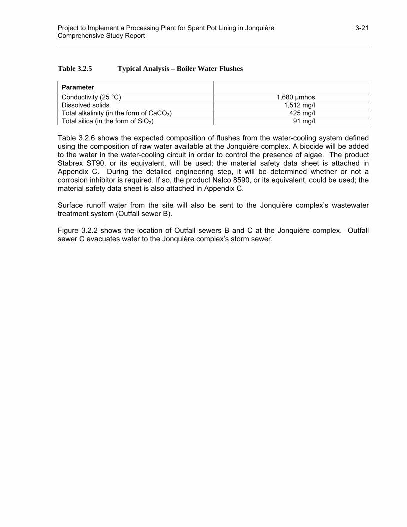
Project to Implement a Processing Plant for Spent Pot Lining in Jonquière 3-21 Comprehensive Study Report
Table 3.2.5 Typical Analysis – Boiler Water Flushes
Parameter Conductivity (25 °C) 1,680 µmhos Dissolved solids 1,512 mg/l Total alkalinity (in the form of CaCO3) 425 mg/l Total silica (in the form of SiO2) 91 mg/l
Table 3.2.6 shows the expected composition of flushes from the water-cooling system defined using the composition of raw water available at the Jonquière complex. A biocide will be added to the water in the water-cooling circuit in order to control the presence of algae. The product Stabrex ST90, or its equivalent, will be used; the material safety data sheet is attached in Appendix C. During the detailed engineering step, it will be determined whether or not a corrosion inhibitor is required. If so, the product Nalco 8590, or its equivalent, could be used; the material safety data sheet is also attached in Appendix C. Surface runoff water from the site will also be sent to the Jonquière complex’s wastewater treatment system (Outfall sewer B). Figure 3.2.2 shows the location of Outfall sewers B and C at the Jonquière complex. Outfall sewer C evacuates water to the Jonquière complex’s storm sewer.
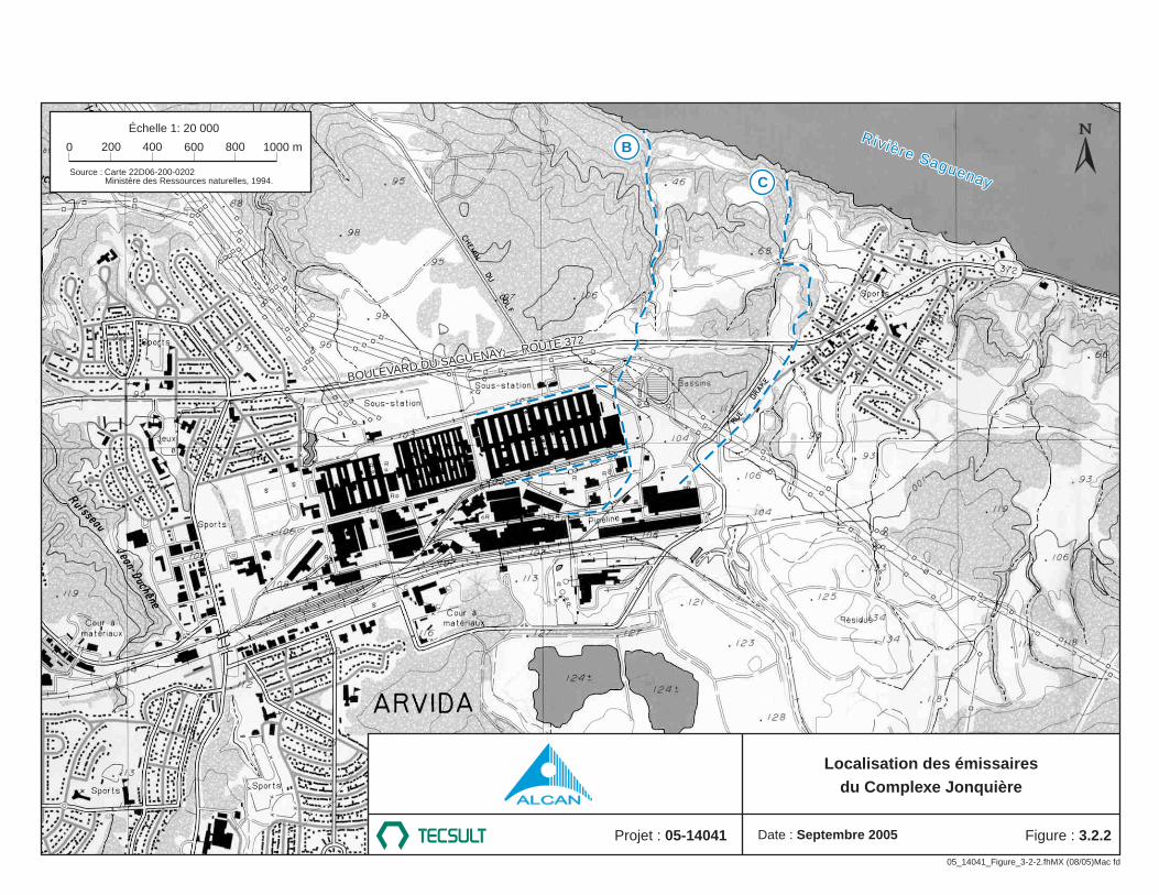
BOULEVARD DU SAGUENAY — ROUTE 372
Rivière Saguenay
Rivière Saguenay
B
C
BOULEVARD DU SAGUENAY — ROUTE 372
05_14041_Figure_3-2-2.fhMX (08/05)Mac fd
Date : Septembre 2005Projet : 05-14041 Figure : 3.2.2
Localisation des émissairesdu Complexe Jonquière
0 200 400 600 800 1000 m
Échelle 1: 20 000
Source : Carte 22D06-200-0202Ministère des Ressources naturelles, 1994.

Project to Implement a Processing Plant for Spent Pot Lining in Jonquière 3-23 Comprehensive Study Report
3.2.2 Correspondence Table Échelle 1 : 20 000 Scale 1:20,000 Source : Carte 22D06-200-0202 Source: Map 22D06-200-0202 Ministère des Ressources naturelles, 1994 Ministère des Ressources naturelles, 1994 Boulevard du Saguenay – Route 372 Saguenay Boulevard – Highway 372 Rivière Saguenay Saguenay River Ruisseau Jean-Duchêne Jean-Duchêne Creek Rue Drake Drake Street

Project to Implement a Processing Plant for Spent Pot Lining in Jonquière 3-24 Comprehensive Study Report
Table 3.2.6 Planned Composition – Flushes from the Cooling Water System
Parameter Total alkalinity (in the form of CaCO3) Total aluminium 3.5 mg/l Total arsenic (in the form of As) 0.014 mg/l Bromine (from the biocide) 0.1 mg/l Total cadmium (in the form of Cd) 0.07 mg/l Total organic carbon 35 mg/l Chloride 56 mg/l Total chromium (in the form of Cr) 0.35 mg/l Total cobalt (in the form of Co) 0.21 mg/l Total copper (in the form of Cu) 0.14 mg/l Cyanides (in the form of HCN) 0.07 mg/l BOD 21 mg/l COD 62 mg/l Total iron (in the form of Fe) 3.0 mg/l Total oil and grease/fat 10 mg/l Total mercury (in the form of Hg) 0.0021 mg/l Total nickel (in the form of Ni) 0.21 mg/l Phosphate (in the form of PO4) 0.56 mg/l Lead (in the form of Pb) 0.7 mg/l Dissolved solids 294 mg/l Suspended solids 3.5 mg/l Sulfates (in the form of SO4) 7 mg/l Total zinc (in the form of Zn) 0.07 mg/l Silica 19.6 mg/l
3.2.4 Solid Discharges
3.2.4.1 Iron Oxides
Iron oxides are formed during the cyanide destruction process. They are then filtered from the solution. Colloidal iron oxides are sent to the red mud disposal site. An estimated 135 metric tons will be disposed of annually (67 t/year of dry material). The approximate composition of this waste is shown in Table 3.2.7. Table 3.2.7 Colloidal Iron Oxide Waste – Approximate Composition
Compound Percentage (weight) Fe2O3 50% H2O 48% NaOH < 1% NaF (in solution form) 1% Al2O3 (in solution form) < 1%