overview of electrochemical spent fuel processing to pyroprocessing.pdf• application of electric...
TRANSCRIPT
National Analytical Management Program (NAMP)
U.S. Department of Energy Carlsbad Field Office
In Cooperation with our University Partners
Radiochemistry Webinars Nuclear Fuel Cycle Series
• Introduction to Pyroprocessing Technology for Used Nuclear Fuel
Meet the Presenter… Dr. Supathorn Phongikaroon
2
Contact Information: Dr. Supathorn Phongikaroon [email protected]
Supathorn Phongikaroon, Ph.D., P.E., is an Associate Professor in the Department of Mechanical and Nuclear Engineering at the Virginia Commonwealth University (VCU). Prior joining VCU in 2014, he was an Assistant Professor in the Department of Chemical and Materials Engineering and Nuclear Engineering Program at the University of Idaho, Idaho Falls Campus (2007 – 2013) and was a Radiochemistry Laboratory lead at the Center for Advanced Energy Studies (2011 – 2013). He has over 10 years of experience in high temperature chemical and electrochemical experiments and detection for used nuclear fuel separations and processes.
Currently, he is the lead principle investigator (PI ) and co-PI on the 2012, 2013, and 2014 Nuclear Energy University Program (NEUP) projects, respectively, relating to safeguard and material detection and accountability in molten salt for pyroprocessing technology. He has led and collaborated on many electrochemical and chemical separation projects for used nuclear fuel since 2004 with several national and international laboratories and leading universities. He has authored and co-authored more than 20 peer-reviewed publications, and given over 50 presentations about molten salt system at national and international conferences and workshops.
Dr. Supathorn Phongikaroon, P.E. Department of Mechanical and Nuclear Engineering Virginia Commonwealth University
Introduction to Pyroprocessing
Technology for Used Nuclear Fuel
National Analytical Management Program (NAMP)
U.S. Department of Energy Carlsbad Field Office
TRAINING AND EDUCATION SUBCOMMITTEE

Topics to be Covered
• Technology Overview
• Electrorefining
• Thermal Processing
• Ceramic Waste Processing
• Current Direction
4

Technology Overview
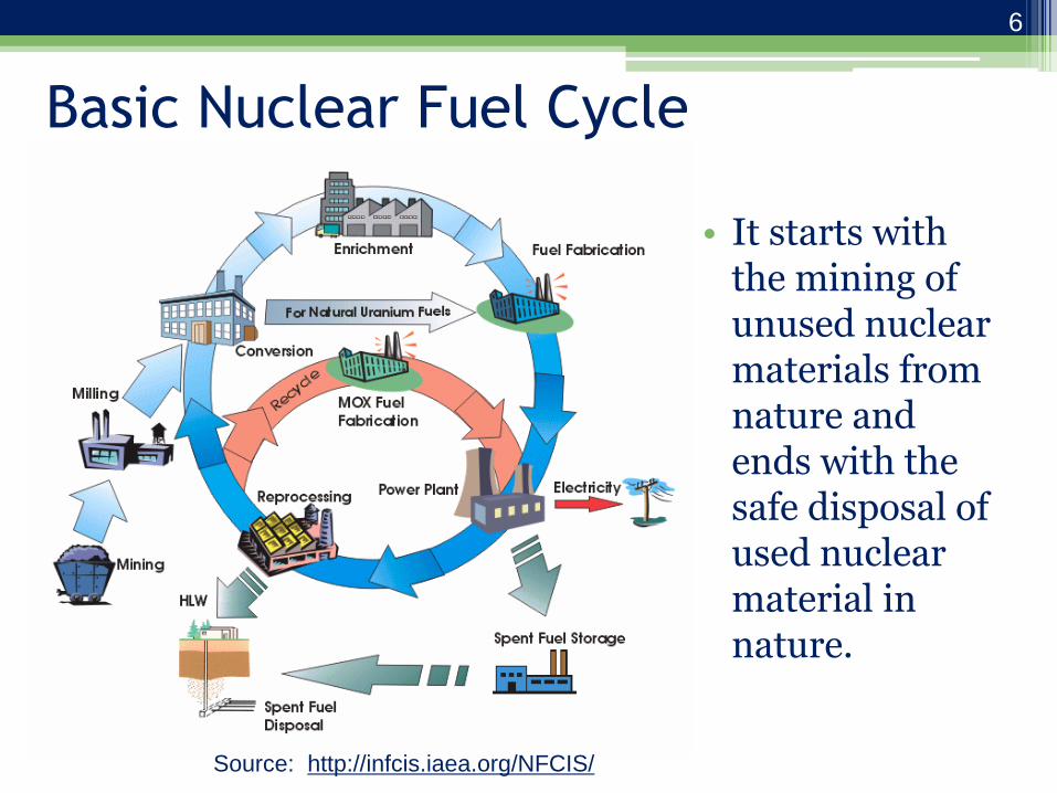
Basic Nuclear Fuel Cycle
• It starts with the mining of unused nuclear materials from nature and ends with the safe disposal of used nuclear material in nature.
Source: http://infcis.iaea.org/NFCIS/
6

Pyroprocessing Technology (aka
Electrochemical or Electrometallurgical Processing)
• Developed at Argonne National Laboratory under the Integral Fast Reactor program in 1980s to provide
− Compact, on-site used fuel separations and fuel fabrication
− Efficient handling of sodium bonding
− Critically-safe conditions for processing high enriched fuel
− Robust method for processing high burnup fuel (avoid organic solvents)
• General characteristics − Dry process, employing molten metals and molten salts
− High temperature process (T >450 C)
− Electrochemical separation of actinides from fission products, cladding, and sodium
− Conversion of sodium metal to sodium chloride
− Initially not designed to recover pure Pu (in contrast with PUREX)
7

Pyroprocessing History • In 1950s and 1960s, many processes were
developed. − Slagging and fluxing of molten metals
− Melt refining or “oxidative slagging”
− Molten zone refining
− Extraction of molten metal by immiscible molten metals and salts
• In 1970s, more processes were developed − Electrolysis or electrorefining
− Fluorination and chlorination of oxide materials
− Direct oxide reduction
− Molten salt extraction
• Present generation of pyrochemical processing for recycling or treating used fuel started in the 1980s.
− IFR program for recycle of EBR-II fuel
− EBR-II Used Fuel Treatment program for fuel stabilization and waste disposal
8

Experimental Breeder Reactor-II • EBR-II was a metallic-fueled
sodium-cooled, fast reactor. – Operated from 1963 to 1995.
– Uranium-10 wt % zirconium driver fuel.
– High enrichment driver fuel (67-78%)
– DU blanket (1% Pu--used for breeding)
– High burnup (>30 atom %) achieved in some fuel pins.
– All fuel sodium bonded
• Demonstration test reactor for Integral Fast Reactor System (1984 to 1995).
• Reactor shut down in 1995
22.4 tons blanket 3.1 tons driver
9
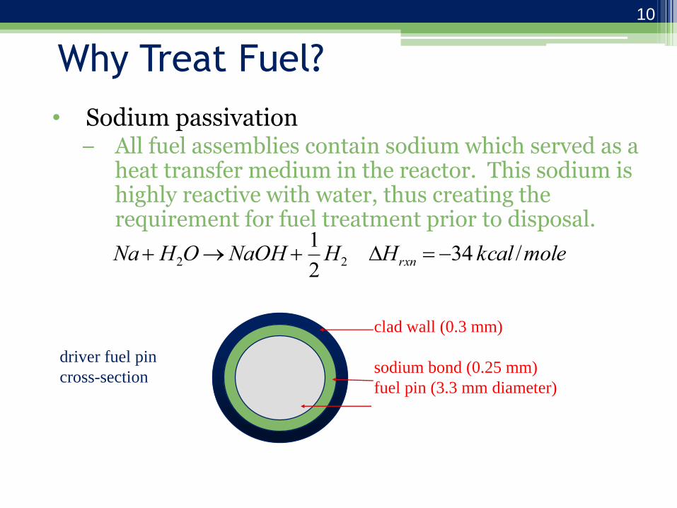
Why Treat Fuel?
• Sodium passivation − All fuel assemblies contain sodium which served as a
heat transfer medium in the reactor. This sodium is highly reactive with water, thus creating the requirement for fuel treatment prior to disposal.
Na H2ONaOH 1
2H2 Hrxn 34 kcal /mole
clad wall (0.3 mm)
sodium bond (0.25 mm)
fuel pin (3.3 mm diameter)
driver fuel pin
cross-section
10

Why Treat Fuel?
• Waste volume minimization
–Recycle actinides
–Concentrate fission products into stable waste forms
• Recovery of plutonium and minor actinides
–TRU recovery should be demonstrated for future applications of pyroprocessing technology
–Key component of waste management
11

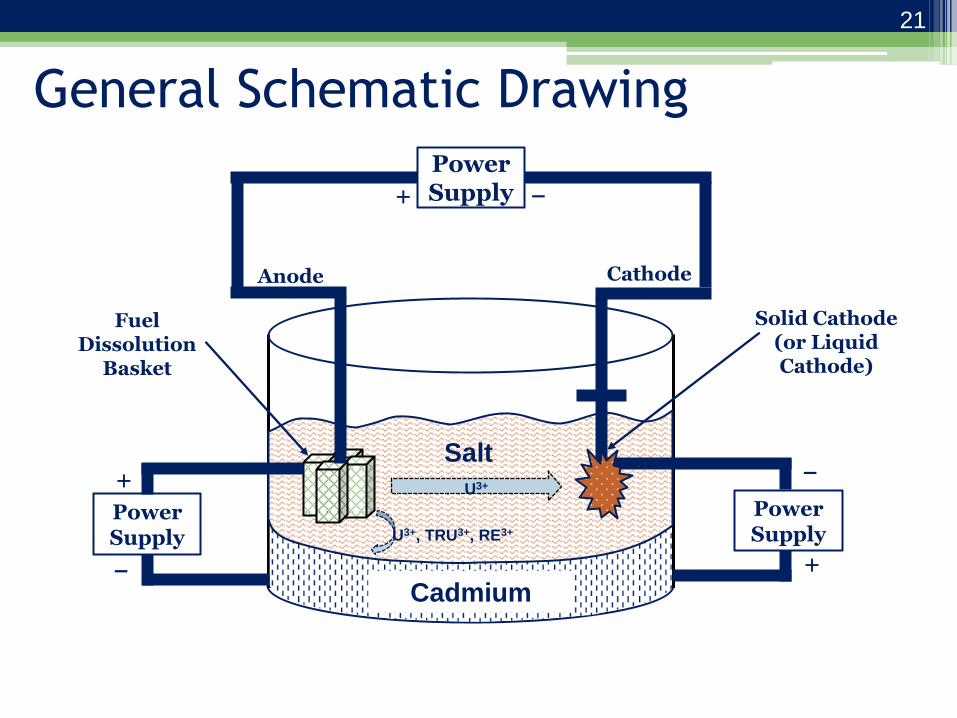
General Process Description
• Electrorefiner (ER) consisting of molten
chloride salt;
• Used fuel loaded into baskets at anode;
• Application of electric current for the
dissolution of uranium, transuranics and metal
fission products;
• Reduction and recovery of pure uranium at a
steel cathode; and
• Uranium-transuranics mixture recovered from
secondary cathode (molten cadmium)
12
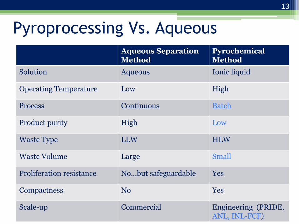
Pyroprocessing Vs. Aqueous
Aqueous Separation Method
Pyrochemical Method
Solution Aqueous Ionic liquid
Operating Temperature Low High
Process Continuous Batch
Product purity High Low
Waste Type LLW HLW
Waste Volume Large Small
Proliferation resistance No…but safeguardable Yes
Compactness No Yes
Scale-up Commercial Engineering (PRIDE, ANL, INL-FCF)
13

EBR-II Used Fuel Treatment Process
14

Advanced Conceptual design
15

Advantages of Advanced Flowsheet
• Accommodates oxide fuel feed
• Recovers actinides for recycled fuel fabrication
• Reduces high level waste volume
• Improves efficiency of actinide recycle
16

High-Level Wastes
• Two high-level wastes are produced from pyrochemical processing.
• A sodalite-based ceramic waste stabilizes fission products that form chlorides.
• A stainless-steel-15% zirconium metal waste stabilizes cladding hulls and more noble fission products.
17

Electrorefining

EBR-II Used Fuel Treatment Process
19

The Heart of Pyroprocessing
Tech.
• Runs at high temperature (450-500 C) with molten LiCl-KCl electrolyte.
• Purified U metal collected on cathode.
• Cadmium chloride is used as an oxidant.
• Cadmium pool captures materials and can be used as an anode for clean-up.
Anode: U (anode) U3+(salt) + 3e- Cathode: U3+(salt) + 3e- U(cathode) Net reaction: U(anode) U(cathode) ELECTROREFINER (ER)
Sample ingot
Westphal and Mariani, J Minerals Metals & Mat Society, 52, 21-25 (2002).
20
Cadmium
Salt
Power Supply + −
Anode Cathode
Power Supply
Power Supply
+
+ −
−
Fuel Dissolution
Basket
Solid Cathode (or Liquid Cathode)
U3+
U3+, TRU3+, RE3+
General Schematic Drawing
21
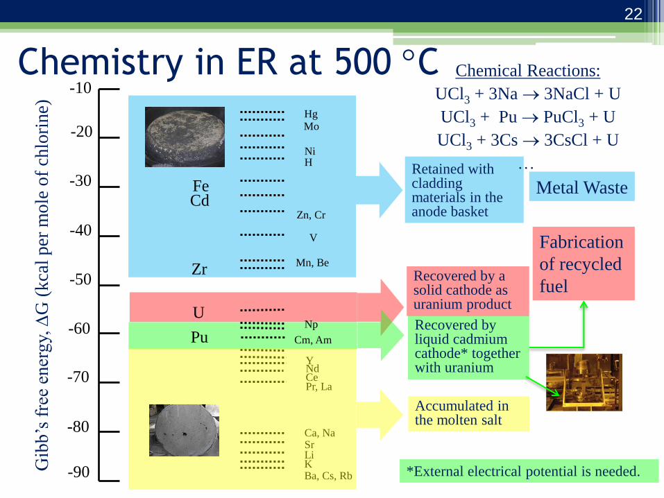
Chemistry in ER at 500 C -10
-20
-30
-40
-50
-60
-70
-80
-90 Gib
b’s
fre
e en
erg
y,
G (
kca
l per
mole
of
chlo
rine)
Hg Mo
Ni H
Zn, Cr
V
Mn, Be
Np
Cm, Am
Y
Ca, Na Sr
K Ba, Cs, Rb
Li
Fe Cd
Zr
U
Pu
Nd Ce Pr, La
Retained with cladding materials in the anode basket
Metal Waste
Recovered by a solid cathode as uranium product
Fabrication
of recycled
fuel
Recovered by liquid cadmium cathode* together with uranium
Accumulated in the molten salt
Chemical Reactions:
UCl3 + 3Na 3NaCl + U
UCl3 + Pu PuCl3 + U
UCl3 + 3Cs 3CsCl + U
*External electrical potential is needed.
22
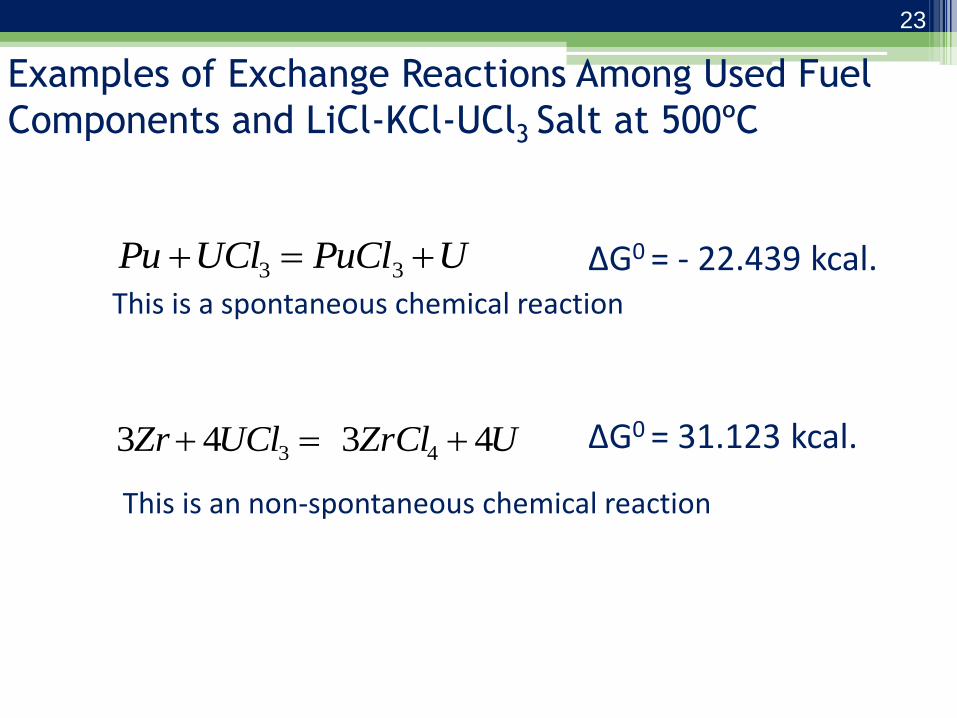
Examples of Exchange Reactions Among Used Fuel
Components and LiCl-KCl-UCl3 Salt at 500ºC
UPuClUClPu 33
UZrClUClZr 4343 43
This is a spontaneous chemical reaction
ΔG0 = - 22.439 kcal.
ΔG0 = 31.123 kcal.
This is an non-spontaneous chemical reaction
23
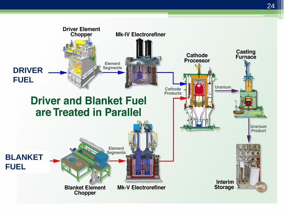
DRIVER
FUEL
BLANKET
FUEL
24

Challenge to Recover All Actinides
• Theoretically, the activity ratio of Pu to U in LiCl-KCl salt needs to be approximately 106 in order to produce a plutonium deposit on a solid cathode at 773 K.
• Pu and U can be co-deposited in liquid cadmium because the activity coefficient for plutonium in Cd phase is very small (~10-4) − The Pu to U ratio in the LiCl-KCl salt must theoretically
be greater than three to co-deposit uranium and plutonium in a liquid cadmium cathode.
Possible approach—Liquid Cadmium Cathode
Vaden et al., Nuclear Technology, 162, 124-128 (2008).
25
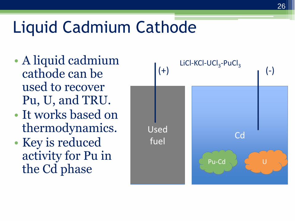
Liquid Cadmium Cathode
• A liquid cadmium cathode can be used to recover Pu, U, and TRU.
• It works based on thermodynamics.
• Key is reduced activity for Pu in the Cd phase
Cd
Pu-Cd U
(-)
Used fuel
(+) LiCl-KCl-UCl3-PuCl3
26
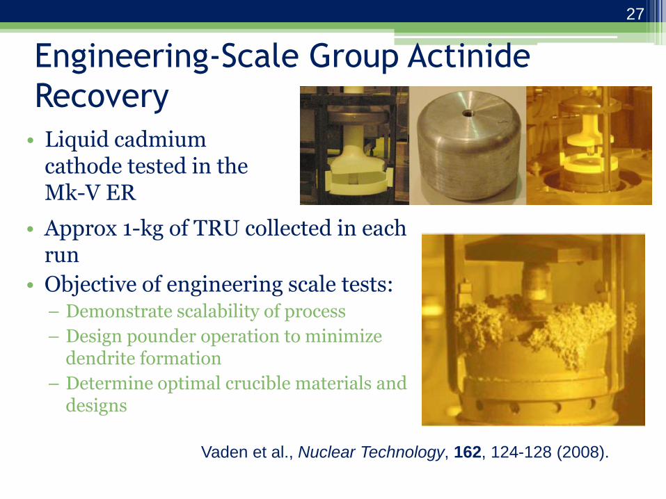
Engineering-Scale Group Actinide
Recovery
• Liquid cadmium cathode tested in the Mk-V ER • Approx 1-kg of TRU collected in each run
• Objective of engineering scale tests: – Demonstrate scalability of process
– Design pounder operation to minimize dendrite formation
– Determine optimal crucible materials and designs
Vaden et al., Nuclear Technology, 162, 124-128 (2008).
27
27
Summary
• Differences in free energy of formation between chloride salts of fuel constituents allow for easy separation of fission products and actinides.
• Standard ER operation results in dendritic, pure U deposits at a cathode.
• Engineering-scale ERs operated for 10+ years at INL (previously ANL-West) for treating used EBR-II fuel.
• Liquid cadmium cathode can be used to co-deposit U, Pu, and minor actinides.
28
Thermal Processing
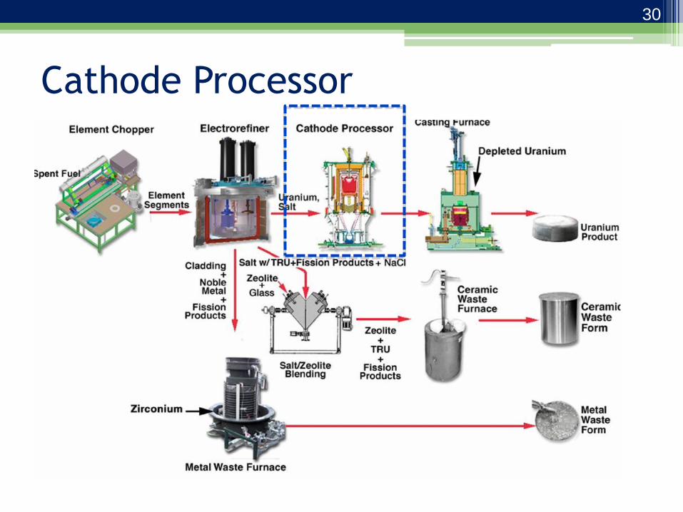
Cathode Processor
30
Cathode Processing
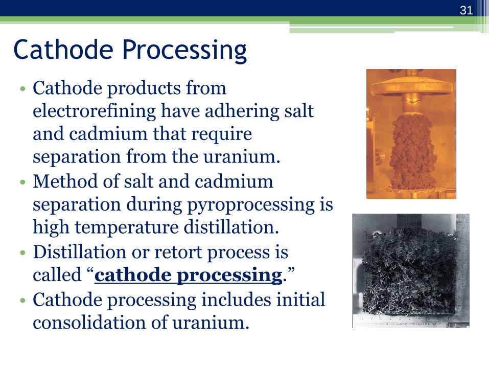
• Cathode products from electrorefining have adhering salt and cadmium that require separation from the uranium.
• Method of salt and cadmium separation during pyroprocessing is high temperature distillation.
• Distillation or retort process is called “cathode processing.”
• Cathode processing includes initial consolidation of uranium.
31
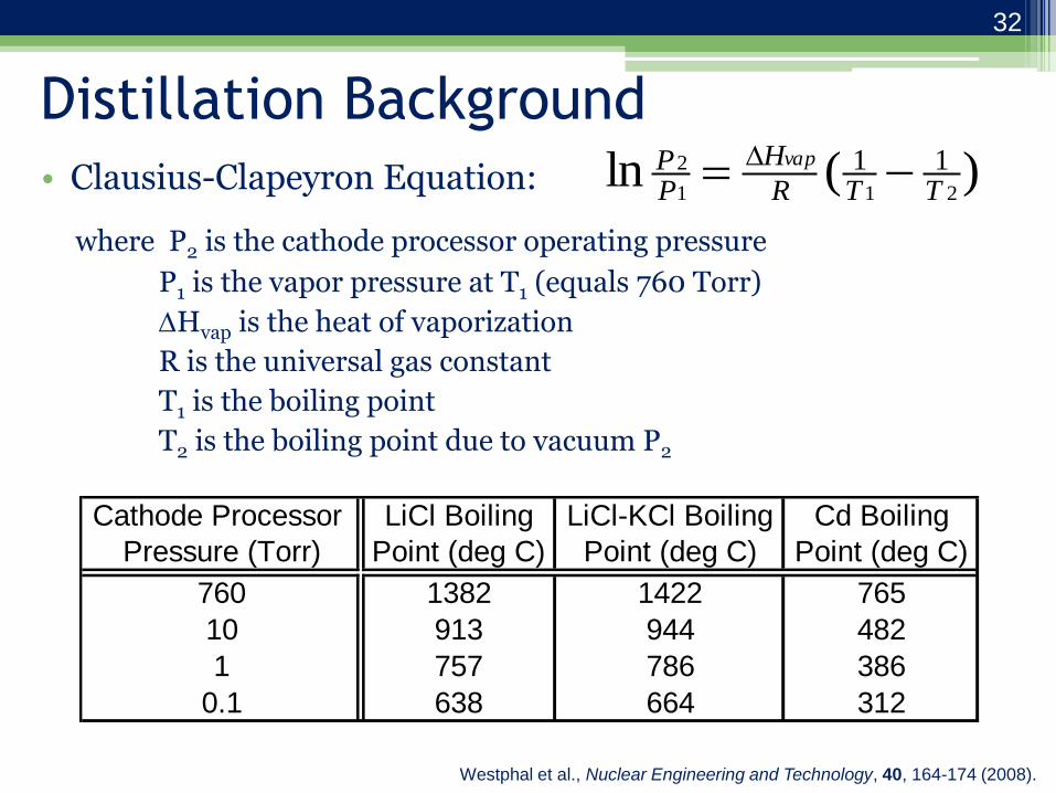
Distillation Background
• Clausius-Clapeyron Equation:
where P2 is the cathode processor operating pressure
P1 is the vapor pressure at T1 (equals 760 Torr)
Hvap is the heat of vaporization
R is the universal gas constant
T1 is the boiling point
T2 is the boiling point due to vacuum P2
)(ln211
2 11TTR
H
PP vap
Cathode Processor LiCl Boiling LiCl-KCl Boiling Cd Boiling
Pressure (Torr) Point (deg C) Point (deg C) Point (deg C)
760 1382 1422 765
10 913 944 482
1 757 786 386
0.1 638 664 312
Westphal et al., Nuclear Engineering and Technology, 40, 164-174 (2008).
32

Cathode Processor Products
Uranium
Salt Westphal et al., ANS 5th Topical Meeting, Charleston, SC (2002): http://www.ipd.anl.gov/anlpubs/2002/07/43801.pdf
33
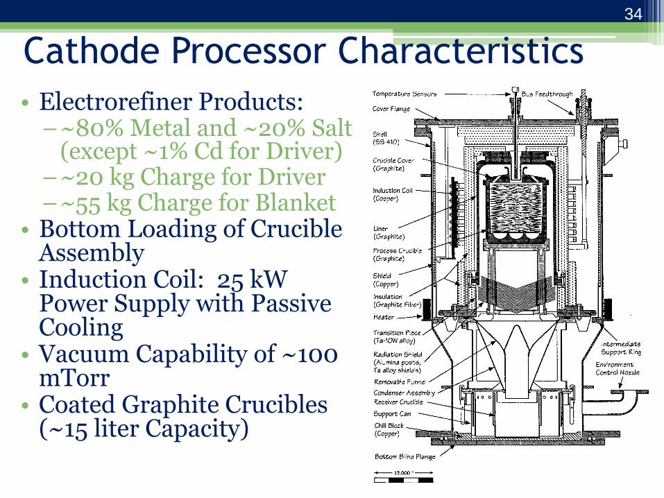
Cathode Processor Characteristics
• Electrorefiner Products: –~80% Metal and ~20% Salt
(except ~1% Cd for Driver) –~20 kg Charge for Driver –~55 kg Charge for Blanket
• Bottom Loading of Crucible Assembly
• Induction Coil: 25 kW Power Supply with Passive Cooling
• Vacuum Capability of ~100 mTorr
• Coated Graphite Crucibles (~15 liter Capacity)
34
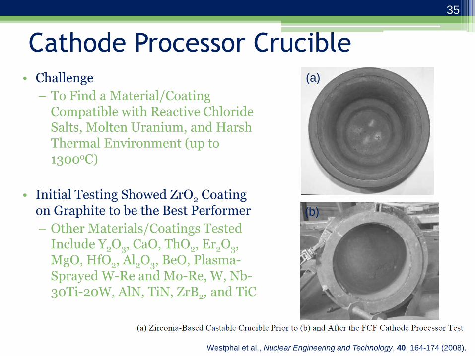
Cathode Processor Crucible • Challenge
– To Find a Material/Coating Compatible with Reactive Chloride Salts, Molten Uranium, and Harsh Thermal Environment (up to 1300oC)
• Initial Testing Showed ZrO2 Coating on Graphite to be the Best Performer
– Other Materials/Coatings Tested Include Y2O3, CaO, ThO2, Er2O3, MgO, HfO2, Al2O3, BeO, Plasma-Sprayed W-Re and Mo-Re, W, Nb-30Ti-20W, AlN, TiN, ZrB2, and TiC
(a)
(b)
Westphal et al., Nuclear Engineering and Technology, 40, 164-174 (2008).
35

Cathode Processor Crucible (cont.) • ZrO2 on Graphite
– Advantages
• Compatible with Chloride Salt and Uranium
• Graphite Suscepts and is Durable
• Easily Applied
– Disadvantages
• Cleaning and Recoating
• Dross Formation Resulting in 2-3 wt. % U Loss (ZrO2+U => UO2+Zr)
• Under Development
– HfN Coating on Metal Substrate
– Castable Materials
(a) Hafnium nitride coated crucible prior
to (b) after the first FCF cathode
processor test.
(a) (b)
36
Cathode Processor Crucible Development
• HfN-coated Nb crucible: – Several tests with irradiated products have shown minimal signs
of reaction.
– Tests will continue with irradiated products to confirm compatibility.
– Pursuing scale-up to >15 liter.
• Zirconia castable with graphite: – Tests with irradiated products have been performed at both mid-
scale (9 liter) and full-scale (15 liter).
– Pro: Elimination of crucible cleaning.
– Con: Slight uranium loss due to reaction.
Westphal et al., Nuclear Engineering and Technology, 40, 164-174 (2008).
37

Cadmium Distillation
Actinide metal product
Distilled Cd + salt
Westphal et al., Journal of Alloys and Compounds, 444-445, 561-564 (2007).
38

Casting Furnace
39
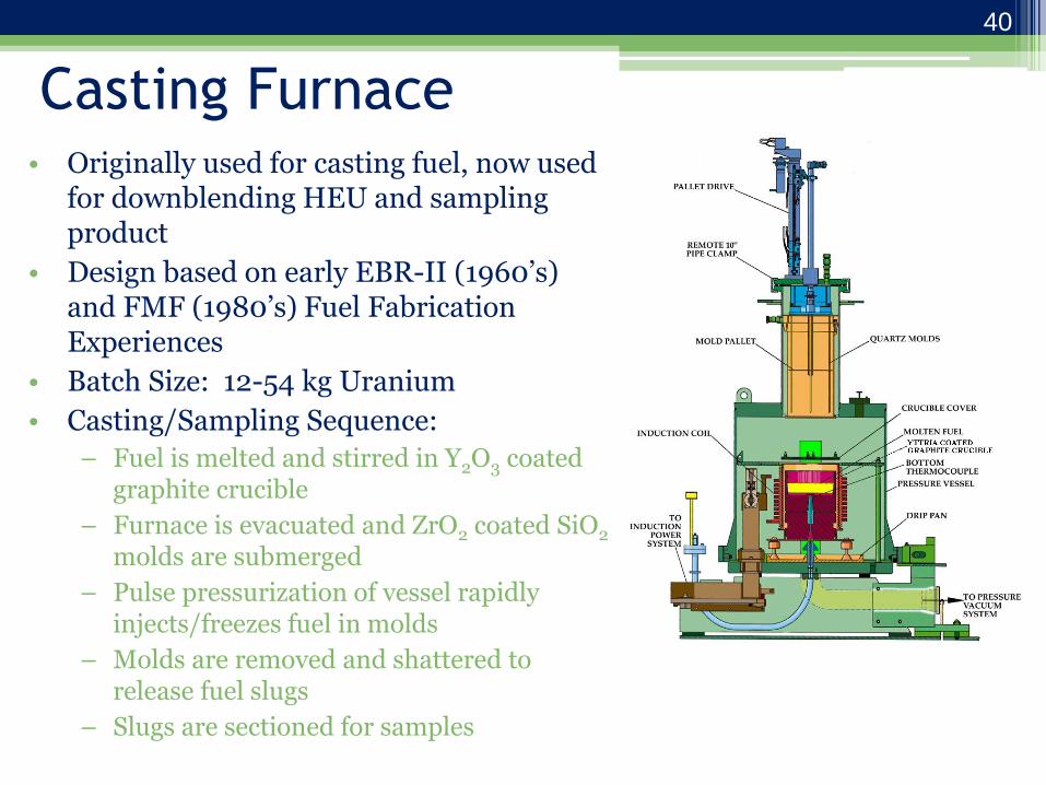
Casting Furnace • Originally used for casting fuel, now used
for downblending HEU and sampling product
• Design based on early EBR-II (1960’s) and FMF (1980’s) Fuel Fabrication Experiences
• Batch Size: 12-54 kg Uranium
• Casting/Sampling Sequence:
– Fuel is melted and stirred in Y2O3 coated graphite crucible
– Furnace is evacuated and ZrO2 coated SiO2 molds are submerged
– Pulse pressurization of vessel rapidly injects/freezes fuel in molds
– Molds are removed and shattered to release fuel slugs
– Slugs are sectioned for samples
40

Metal Waste Furnace
41
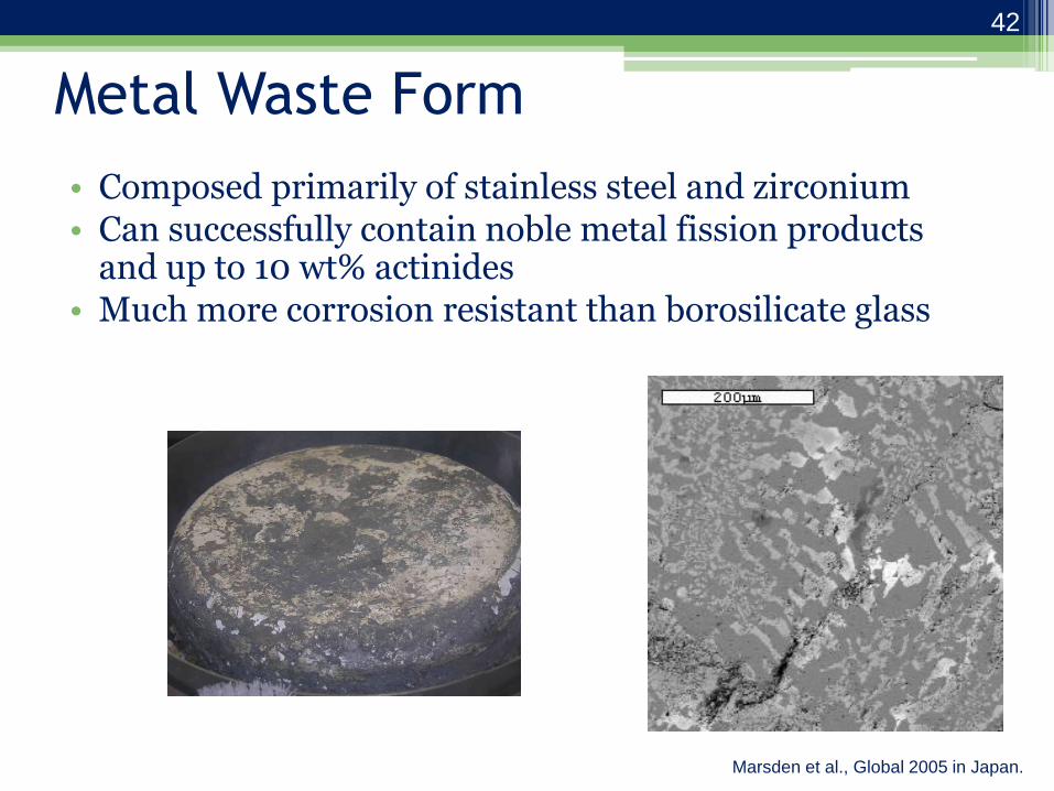
Metal Waste Form
• Composed primarily of stainless steel and zirconium • Can successfully contain noble metal fission products
and up to 10 wt% actinides • Much more corrosion resistant than borosilicate glass
Marsden et al., Global 2005 in Japan.
42

Constituents of the Metal Waste
• Cladding hulls and plenum sections
• Residual Zr (driver fuel)
• Residual metallic sodium (from plenum)
• Noble metal fission products
• Undissolved actinides (typically less than 3%)
43

Functionality of the Metal Waste
Furnace
• Metallic sodium in the cladding plenum sections is reacted with ferrous chloride to form stable sodium chloride and metallic iron.
• Salts (primarily LiCl, KCl, and NaCl) are vacuum distilled from the cladding hulls between 800-1350oC.
• Hulls and zirconium wire are melted and alloyed for approximately three hours at 1600°C to form a homogeneous alloy.
44

Why Add Zr Wire?
• Eutectic point results in low melting point (1300oC).
• Maximum sustained operating temperature of the furnace is 1600oC).
Stein et al. (2002), J. Phase Equilibria, 23(6), 480-494.
Metal waste range
45
Metal Processing Summary
• Cathode processor removes salt and/or cadmium from actinide deposits formed at ER cathode.
• Casting furnace used for multiple purposes: –Product sampling; –Downblending HEU; and –Fuel fabrication.
• Metal waste furnace removes salt from cladding hulls and forms melts Zr-rich alloy that becomes a high level waste (contains noble metal fission products).
46
Ceramic Waste Processing
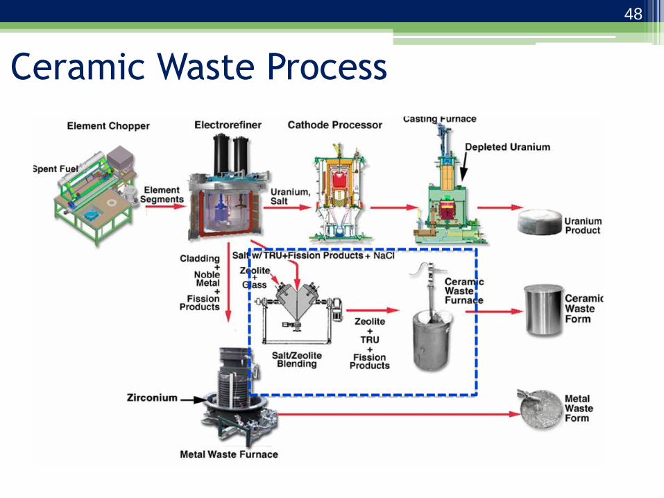
Ceramic Waste Process
48

Electrorefiner Salt Contamination
• Contaminants accumulate in the electrorefiner:
• What dictates the usable life of the salt? – NaCl concentration in the case of sodium-bonded fuel
(melting point) – Fission product chloride concentration in the case of other
fuel (decay heat) – Plutonium concentration in the case of Pu-rich used fuel
Fission products (CsCl, SrCl2, CeCl3…)
NaCl (sodium bonded fuel)
LiCl-KCl
Simpson (2012): http://www5vip.inl.gov/technicalpublications/documents/5411188.pdf
49
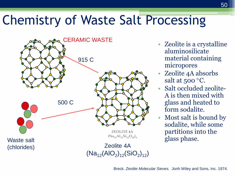
Chemistry of Waste Salt Processing
• Zeolite is a crystalline aluminosilicate material containing micropores
• Zeolite 4A absorbs salt at 500 C.
• Salt occluded zeolite-A is then mixed with glass and heated to form sodalite.
• Most salt is bound by sodalite, while some partitions into the glass phase.
Waste salt
(chlorides) Zeolite 4A
(Na12(AlO2)12(SiO2)12)
500 C
915 C
CERAMIC WASTE
Breck. Zeolite Molecular Sieves. Jonh Wiley and Sons, Inc. 1974.
50

Salt Occlusion in Zeolite-A
• This is known as the “throw-away process,” since it involves discarding all of the salt, including the useful LiCl and KCl
• Approximately 10 wt% salt is accommodated in the zeolite-A structure
• Since fission product concentration will not exceed 30 wt% in the salt, this means that only 3 wt% fission product loading possible in this waste form.
• This is good motivation for developing an advanced, selective process.
51

MILL/CLASSIFIER
ZEOLITE DRYER
HEATED V-MIXER
Ground
Salt
Dried
Zeolite Glass and
Salt-Loaded
Zeolite
CERAMIC WASTE
SALT CRUSHER
Crushed
Salt
ELECTROREFINER
Electrorefiner
Salt
Glass added
after
producing salt-
loaded zeolite
FURNACE
ZEOLITE MILL
Milled
Zeolite
“Throw Away” Ceramic Waste Process
52

Zeolite Drying • Zeolite-4A can hold up to ~20 wt% water in
equilibrium with ambient air.
• Target of 0.2 wt% water in zeolite prior to use in ceramic waste process:
– Minimize corrosion due to salt-water-metal interactions
– Maximize capacity for zeolite to hold salt
– Minimize pores in ceramic waste form • Nominal drying method
– Heat to 550oC
– Apply vacuum
– Keep zeolite fluidized
• Zeolite sample testing:
– Moisture (Karl-Fischer Titration, Near Infrared Absorption)
– Rehydration capacity
53

Salt Solidification and Milling
• Contaminated salt is removed from ER and solidified into cubes.
• These cubes are transferred from Fuel Conditioning Facility (FCF) to Hot Fuels Examination Facility (HFEF)
• ER Salt crushed to < 1.0 cm in size.
• Salt particulate is then ground in high speed mill/classifier to 45-250 m.
54
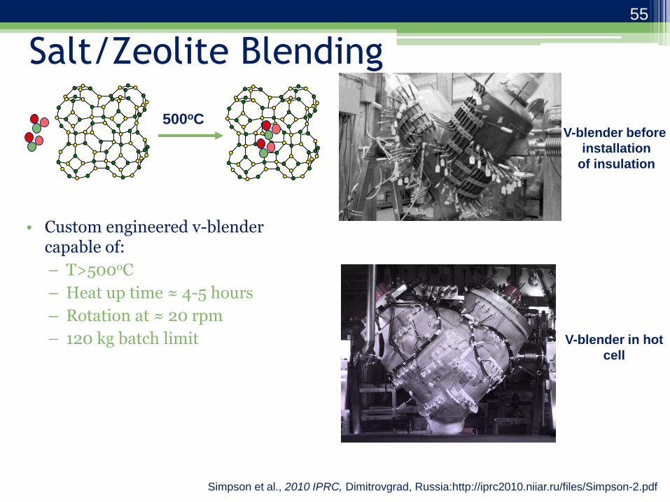
Salt/Zeolite Blending
• Custom engineered v-blender capable of:
– T>500oC
– Heat up time ≈ 4-5 hours
– Rotation at ≈ 20 rpm
– 120 kg batch limit
V-blender before
installation
of insulation
500oC
V-blender in hot
cell
Simpson et al., 2010 IPRC, Dimitrovgrad, Russia:http://iprc2010.niiar.ru/files/Simpson-2.pdf
55

Pressureless Consolidation • After blending salt-loaded zeolite with glass,
conversion to monolithic sodalite waste form is the final step.
• Pressureless consolidation method replaced Hot Isostatic Press after the 1999 technology demonstration for DOE.
• Furnace for out-of-cell, full-scale testing installed in 2005.
– Maximum operating temperature of 1025 °C
– Sealed with atmosphere control
– Capable of processing waste forms 320-400 kg
56
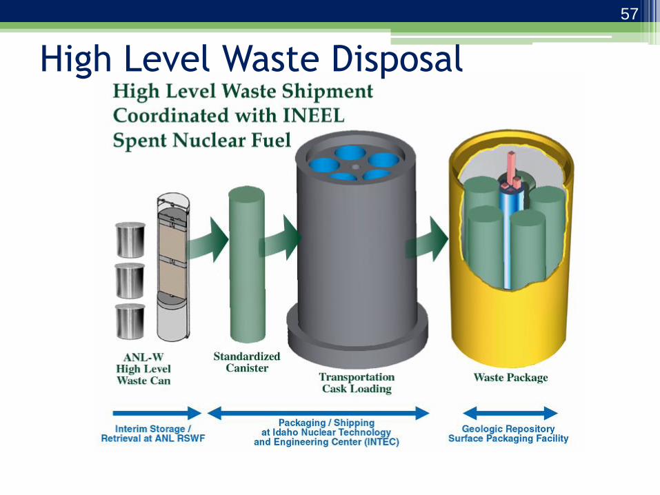
High Level Waste Disposal
57
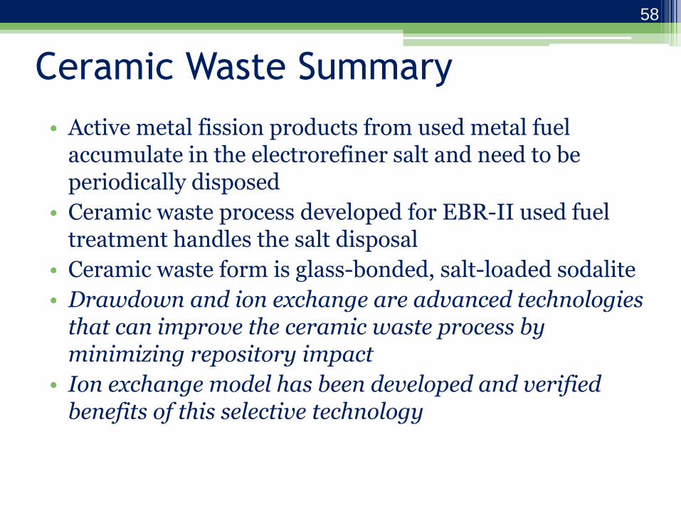
Ceramic Waste Summary
• Active metal fission products from used metal fuel accumulate in the electrorefiner salt and need to be periodically disposed
• Ceramic waste process developed for EBR-II used fuel treatment handles the salt disposal
• Ceramic waste form is glass-bonded, salt-loaded sodalite
• Drawdown and ion exchange are advanced technologies that can improve the ceramic waste process by minimizing repository impact
• Ion exchange model has been developed and verified benefits of this selective technology
58

Current Direction
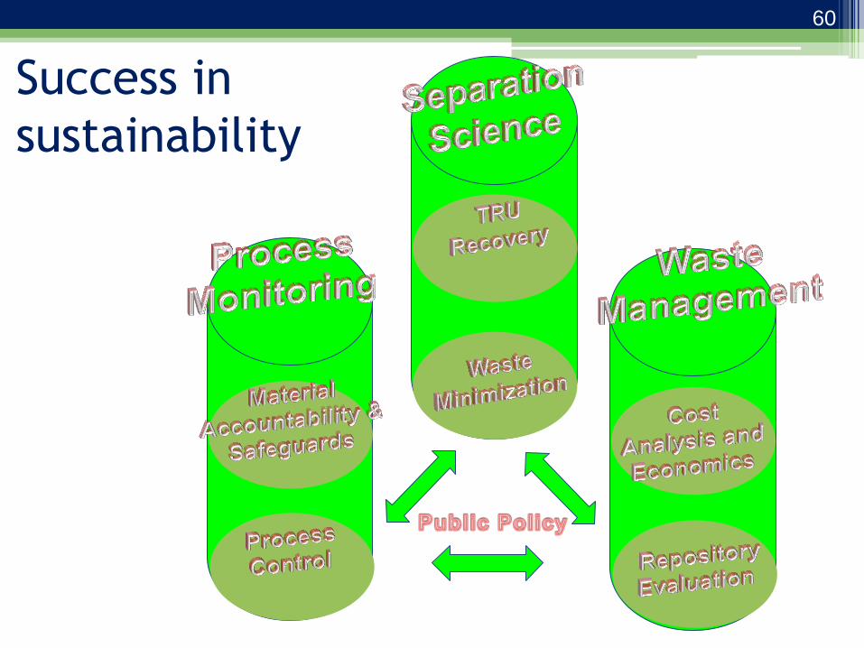
Success in
sustainability
60
National Labs – strengths
• Strong practical processing knowledge and capabilities to handle highly radioactive nuclear materials.
• Access to samples of used fuel and other nuclear waste (salts, metals, oxides).
• Facilities to test processes from bench scale to engineering scale, including both surrogate materials and actual used fuel and waste samples.
• Extensive experience with waste form process development and understanding of regulatory issues related to waste disposal.
• Experts in nuclear non-proliferation and safeguards with strong ties to NNSA and IAEA.
61
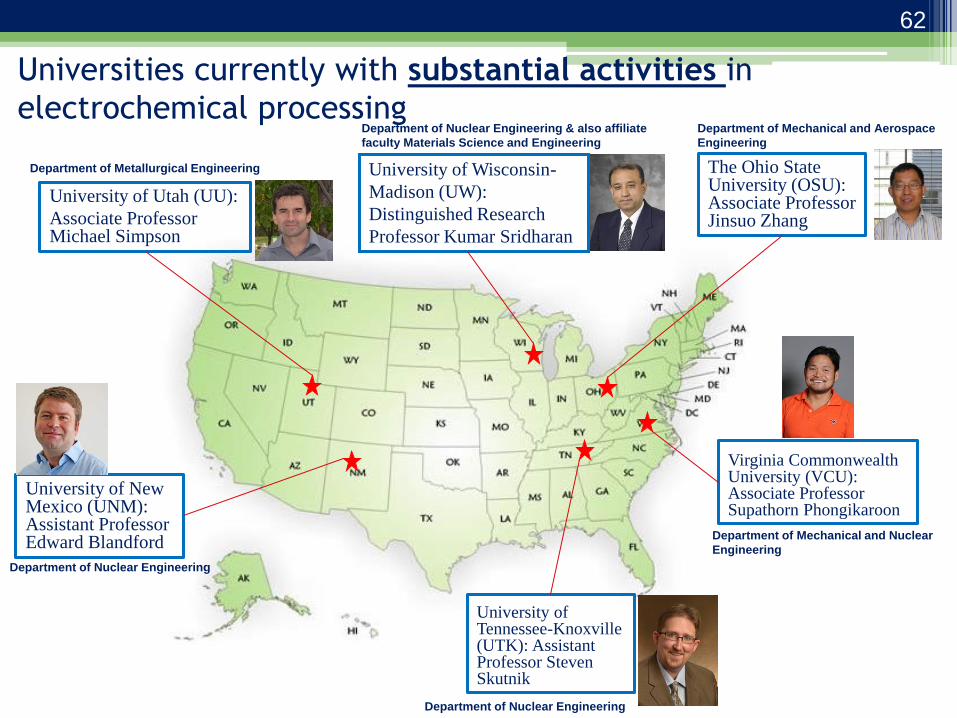
Universities currently with substantial activities in
electrochemical processing
University of Utah (UU):
Associate Professor Michael Simpson
The Ohio State University (OSU): Associate Professor Jinsuo Zhang
University of Wisconsin-
Madison (UW):
Distinguished Research
Professor Kumar Sridharan
University of New Mexico (UNM): Assistant Professor Edward Blandford
University of Tennessee-Knoxville (UTK): Assistant Professor Steven Skutnik
Virginia Commonwealth University (VCU): Associate Professor Supathorn Phongikaroon
Department of Mechanical and Aerospace
Engineering
Department of Nuclear Engineering
Department of Nuclear Engineering
Department of Mechanical and Nuclear
Engineering
Department of Metallurgical Engineering
Department of Nuclear Engineering & also affiliate
faculty Materials Science and Engineering
62
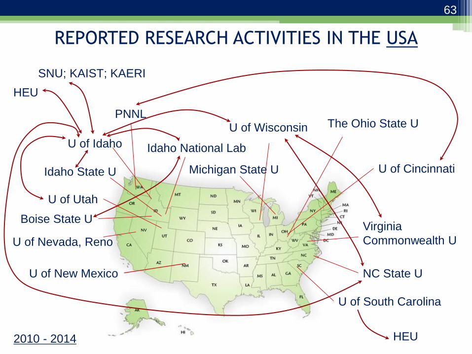
REPORTED RESEARCH ACTIVITIES IN THE USA
U of Idaho
Idaho State U
Boise State U
U of Wisconsin The Ohio State U
U of Utah
U of Nevada, Reno
Idaho National Lab
PNNL
U of Cincinnati
NC State U
Virginia
Commonwealth U
SNU; KAIST; KAERI
HEU
Michigan State U
U of South Carolina
HEU 2010 - 2014
U of New Mexico
63
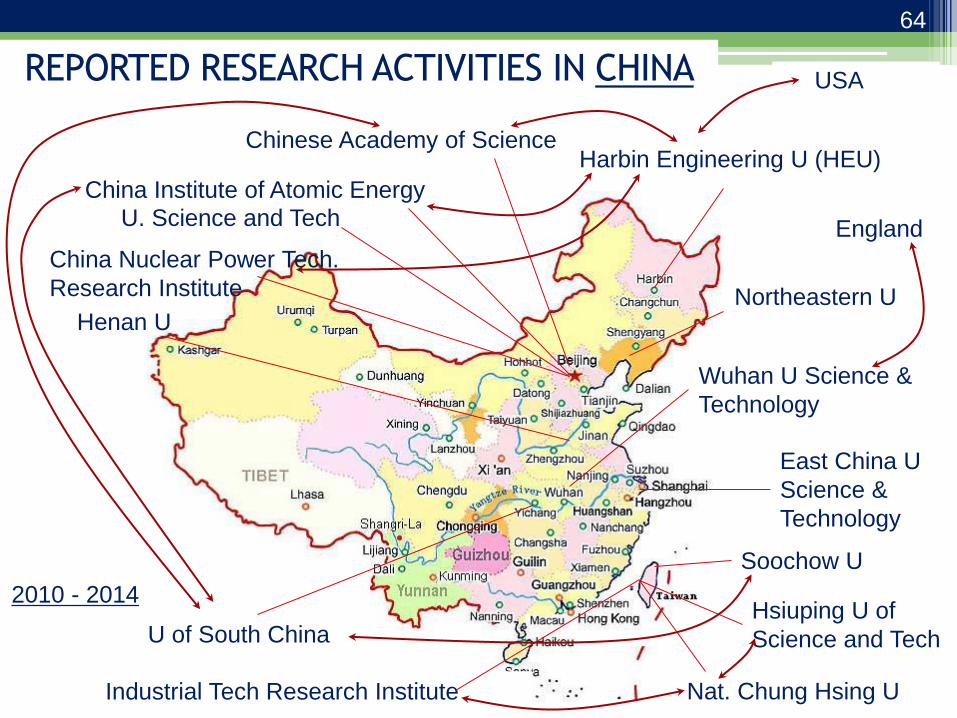
REPORTED RESEARCH ACTIVITIES IN CHINA
Harbin Engineering U (HEU) Chinese Academy of Science
U of South China
Soochow U
China Institute of Atomic Energy
U. Science and Tech
Wuhan U Science &
Technology
East China U
Science &
Technology
Northeastern U Henan U
USA
England
China Nuclear Power Tech.
Research Institute
Hsiuping U of
Science and Tech
Nat. Chung Hsing U Industrial Tech Research Institute
2010 - 2014
64

65
REPORTED RESEARCH ACTIVITIES IN JAPAN
Central Res Inst of Electric
Power Industry (CRIEPI)
Japan Atomic Energy Agency
Doshisha U
Osaka U Kayushu Inst Tech
Nat Inst Adv Ind Sci Tech
Chiba U
Panasonic Corp
Kyoto U Tohoku U
U of Tokyo
Sweden
2010 - 2014
65
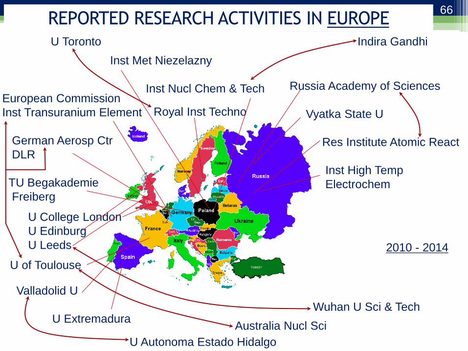
66
REPORTED RESEARCH ACTIVITIES IN EUROPE
Russia Academy of Sciences
Vyatka State U
Res Institute Atomic React
Inst High Temp
Electrochem
Inst Met Niezelazny
Inst Nucl Chem & Tech
U of Toulouse
European Commission
Inst Transuranium Element
German Aerosp Ctr
DLR
TU Begakademie
Freiberg
U College London
U Edinburg
U Leeds
Royal Inst Techno
Valladolid U
U Extremadura
Indira Gandhi
U Autonoma Estado Hidalgo
Australia Nucl Sci
U Toronto
Wuhan U Sci & Tech
2010 - 2014
66

REPORTED RESEARCH ACTIVITIES IN INDIA
SRM U
Indira Gandhi Centre for Atomic Research
Bhabha Atomic Research Center
PSG Coll Technol
Lady Doak College
Inst Nucl Chem & Tech
(Poland)
2010 - 2014
67

Publication in Molten Salt 2010 – 2014 (over
194 papers)
Information from Web of Knowledge
0 5 10 15 20 25 30
China
S. Korea
USA
Japan
India
Europe
Russia
Percentage Distribution
Ranking Journal 1 Electrochimica Acta
2 Journal of Nuclear Materials
3 Journal of Radioanalytical and Nuclear Chemistry
4 Journal of Electrochemical Society
5 Journal of Nuclear Science and Technology
6 Journal of Rare Earth
7 Metallurgical and Materials Transaction B
8 Molten Salt and Ionic Liquid
9 Russian Journal of Electrochemistry
Russian Journal of Physical Chemistry A
Journal of Alloys and Compounds
Acta Metallurgical Sinica
13 International Journal of Electrochemical Science
Journal of Applied Electrochemistry
Nuclear Technology
Journal of Luminescence
Transaction of Nonferrous Metals Society of China
Electrochemistry Communications
19 Chemical Physics Letters
Nuclear Engineering and Technology
Rare Metals
Corrosion
Physical Chemistry Chemical Physics
Chemical Research in Chinese Universities
68

Significant findings
• Growth in molten salt interests among – USA
• More work in late 2013 due to studies sponsored by DOE-NEUP.
– China, • Published articles are from universities with
sponsorship from governmental agencies.
– India, and • Published articles are mostly from the national
laboratory.
– Japan • Published articles are either from the laboratories or
universities collaborating with laboratories/governmental agencies.
69
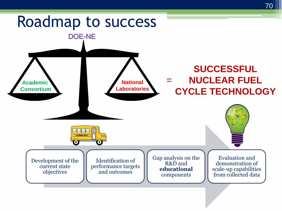
Roadmap to success DOE-NE
Academic
Consortium
National
Laboratories
Development of the current state
objectives
Identification of performance targets
and outcomes
Gap analysis on the R&D and
educational components
Evaluation and demonstration of
scale-up capabilities from collected data
=
SUCCESSFUL
NUCLEAR FUEL
CYCLE TECHNOLOGY
70
Notable References on Pyroprocessing
Technology in the USA • Goff, “Electrochemical Processing of Spent Nuclear Fuel,” Nuclear Regulatory Commission
Seminar presentation. Rockville, MD, March 25, 2008.
• Koch, “EBR-II: An Integrated Experimental Fast Reactor Nuclear Power Station,” American Nuclear Society. 2008.
• Benedict and McFarlane, “EBR-II Spent Fuel Treatment Demonstration Project Status,” Radwaste Magazine, 23-30 July 1998.
• Chang, “The Integral Fast Reactor,” Nuclear Technology, 88, 129-138 (1989).
• Laidler et al., “Development of Pyroprocessing Technology,” Progress in Nuclear Energy, 31, 131-140 (1997).
• Willit et al., “Electrorefining of Uranium and Plutonium-A Literature Review,” Journal of Nuclear Materials, 195, 229-249 (1992).
• Benedict et al., “Pyroprocessing Progress at INL,” Proceedings of Global 2007, Idaho, September 2007.
• Li et al., “Electrorefining Experience for Pyrochemical Processing of Spent EBR-II Driver Fuel,” Proceeding of Global 2005, Japan October 2005.
• National Academy of Sciences, “Electrometallurgical Techniques for DOE Spent fuel Treatment: Final Report,” National Academy Press, 2000.
• Ackerman et al., “Treatment of Wastes in the IFR Fuel Cycle,” Progress in Nuclear Energy, 31, 141-154 (1997).
71

Questions?

Upcoming Webinars in the
Nuclear Fuel Cycle Series
•Nuclear Waste Management-Application to Technetium
•Nuclear Repository Science and the Waste Isolation Pilot Plant
•High Level Waste
NAMP website http://www.wipp.energy.gov/namp/