project overview- strong arm ecen 4160, spring 2005 thaine hock matt corne sammit adhya luz...
TRANSCRIPT

Project Overview- Strong ArmProject Overview- Strong Arm
ECEN 4160, Spring 2005
Thaine Hock
Matt Corne
Sammit Adhya
Luz Quiñónez
Adhya, Corne, Hock, Quinonez 2
Project GoalsProject Goals
To design and build the controlling electronics for a six-axis robotic arm that can be controlled through the use of simple finger motions
Arm will allow paraplegics to control robotic arm in three dimensions
Proof of concept of a larger scale device and training
system

Adhya, Corne, Hock, Quinonez 3
Outline of ApproachOutline of Approach
Microcontroller-Freescale 68MC12
GPIO
LEDDetection
Grid
TouchScreen
RoboticArm-
LynxMotion
LCD-Optrex
FingerSensors
SerialGPIO
Serial
PWMGPIO
FPGA- Xilinx XCS10
CS Signals

Adhya, Corne, Hock, Quinonez 4
Finger SensorsFinger Sensors
Polar Coordinate Control System– Push Buttons and Limit Switches
– Six directions of control
– Grip and Release

Adhya, Corne, Hock, Quinonez 5
Finger DiagramsFinger Diagrams
Limit Switch controls r axis (forward)
/Button controls r axis (back)
Limit Switch controls z axis (up)
/Button controls z axis (down)
Limit Switch controls Φ axis
(right) /Button controls Φ axis (left)Thumb button controls grip
Adhya, Corne, Hock, Quinonez 6
FPGAFPGA
Controls the IR Detection Array– Determine Initial Block Positions
Send Polar Coordinate Position to Micro Controller Using Memory-Mapped Registers
Create all needed glue logic for PCB
Adhya, Corne, Hock, Quinonez 7
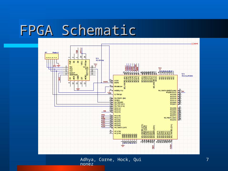
FPGA SchematicFPGA Schematic
Adhya, Corne, Hock, Quinonez 8
ArmArm
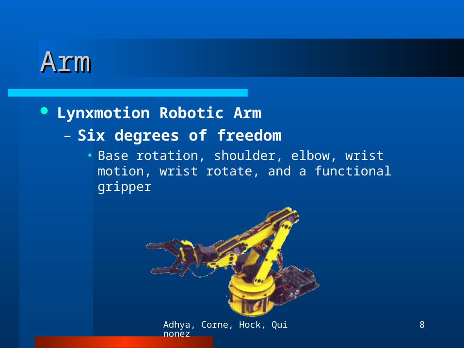
Lynxmotion Robotic Arm– Six degrees of freedom
• Base rotation, shoulder, elbow, wrist motion, wrist rotate, and a functional gripper

Adhya, Corne, Hock, Quinonez 9
Movement CalculationsMovement Calculations

Adhya, Corne, Hock, Quinonez 10
MicrocontrollerMicrocontroller
Compute servo positionsProduce PWM signals to control
servosProcess finger sensor dataProcess touch screen data

Adhya, Corne, Hock, Quinonez 11
Microcontroller SchematicMicrocontroller Schematic

Adhya, Corne, Hock, Quinonez 12
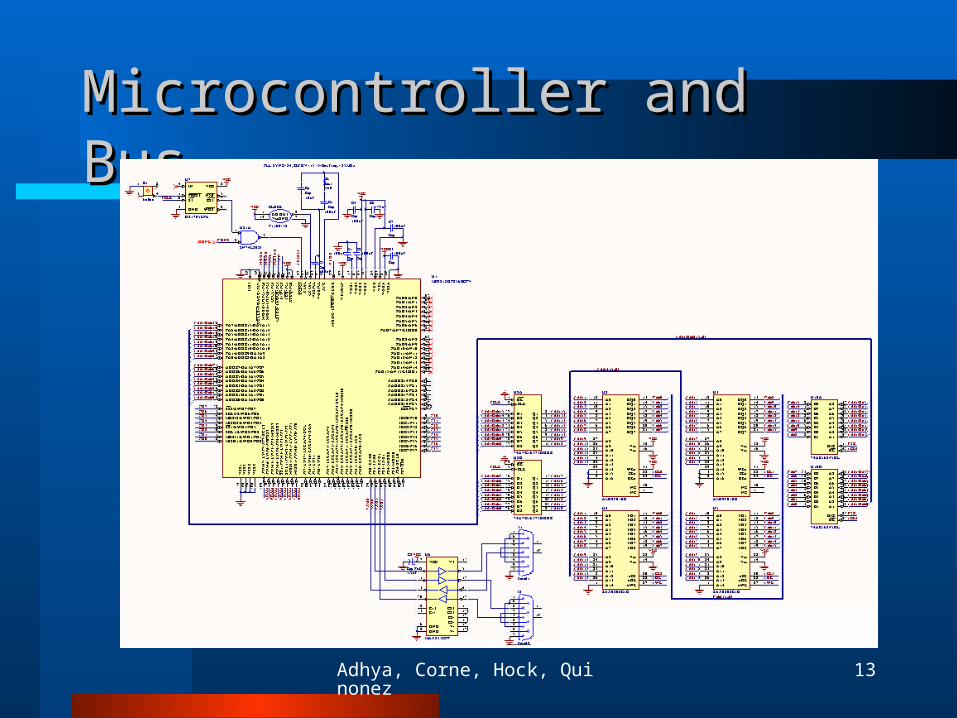
Bus DesignBus Design
Adhya, Corne, Hock, Quinonez 13
Microcontroller and BusMicrocontroller and Bus

Adhya, Corne, Hock, Quinonez 14
PCB LayoutPCB Layout

Adhya, Corne, Hock, Quinonez 15
User InterfaceUser Interface
• QVGA LCD with 8-wire resistive touch screen
• Interfaces to MPU through dual serial interfaces.
• Able to store images in onboard 16Mbit flash memory.

Adhya, Corne, Hock, Quinonez 16
IR SensorsIR Sensors

Adhya, Corne, Hock, Quinonez 17
Parts ListParts ListMicrocontrollerMicrocontroller MC9S12DP256BCPVMicromonitor DS1705EPACMOS SRAM K6X0808C1DCMOS Flash Memory Am29F010B16-bit Bus Tranceiver 74AC16245DL16-bit D Latch 74AVC16373DGGR
FPGAFPGA XCS10-3PC84CPROM XC18V256
MiscellaneousAND gate SN74LS08JPower Jack RAPC712SPST Button PGS125SK43TTL Clock F1100ESM Capacitors T496Diode 1N4008Voltage Regulator LM7805CT
LM78M33C

Adhya, Corne, Hock, Quinonez 18
Startup Software DiagramStartup Software Diagram
Block Pos.
Block Pos.
PowerOn
Initialize68MC12,
FPGA,AndArm
FPGA-Block
Detection
68MC12-Initial Block
Positions
Position Registers
68MC12-Main
Routine
Depending on how many blocks…

Adhya, Corne, Hock, Quinonez 19
Control Software FlowControl Software Flow68MC12-Main
Routine
Poll Finger Sensors
CalculateServo
Positions
GeneratePWM
Signals
No Data
UpdateUser
Interface

Adhya, Corne, Hock, Quinonez 20
Division of LaborDivision of Labor
Finger Sensor– Thaine
FPGA Implementation– Sammit
PCB and Micro controller– Thaine
Robotic Arm Algorithms– Sammit and Matt
IR Sensor and Block Detection– Luz
User Interface– Matt

Adhya, Corne, Hock, Quinonez 21
ScheduleSchedule

Adhya, Corne, Hock, Quinonez 22
MilestonesMilestones
Milestone 1:– User will move robotic arm in one
direction using our commands produced by our board.
Milestone 2:– Robotic arm will be able to pick up and
move a block in 3 dimensions. Also, initial user interface with touch screen will be complete.
Adhya, Corne, Hock, Quinonez 23
Milestone (cont…)Milestone (cont…)
Open Lab:– User ability to control robotic arm in the
relocation of blocks to a predefined location.
– Once task is finished (successful or not), system will locate blocks and reset them to a known operating position.
– User (or helper) will interface with system using a color touch screen.

Adhya, Corne, Hock, Quinonez 24
Risks and Contingency PlanRisks and Contingency Plan
Mapping cylindrical coordinates to servo positions may prove difficult
IR sensors not sensitive enough to detect block positions
Fall Back Plan:– A helper can physically reset system to
known operating state
Adhya, Corne, Hock, Quinonez 25
Cost (BOM)Cost (BOM)
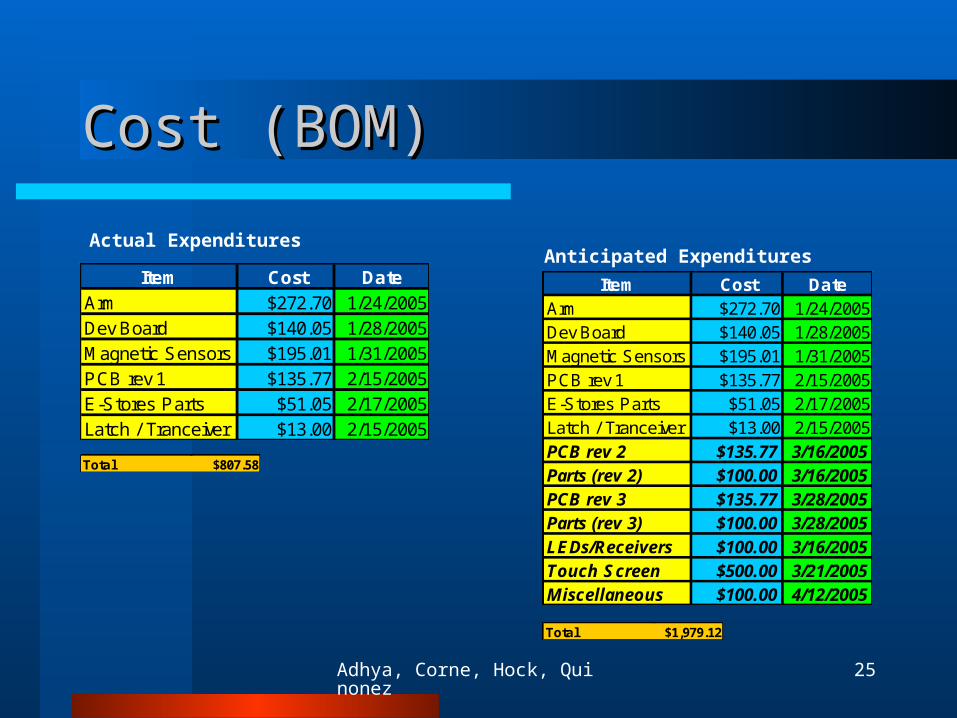
Actual ExpendituresAnticipated Expenditures
Item Cost DateArm $272.70 1/24/2005Dev Board $140.05 1/28/2005Magnetic Sensors $195.01 1/31/2005PCB rev 1 $135.77 2/15/2005E-Stores Parts $51.05 2/17/2005Latch / Tranceiver $13.00 2/15/2005
Total $807.58
Item Cost DateArm $272.70 1/24/2005Dev Board $140.05 1/28/2005Magnetic Sensors $195.01 1/31/2005PCB rev 1 $135.77 2/15/2005E-Stores Parts $51.05 2/17/2005Latch / Tranceiver $13.00 2/15/2005PCB rev 2 $135.77 3/16/2005Parts (rev 2) $100.00 3/16/2005PCB rev 3 $135.77 3/28/2005Parts (rev 3) $100.00 3/28/2005LEDs/Receivers $100.00 3/16/2005Touch Screen $500.00 3/21/2005Miscellaneous $100.00 4/12/2005
Total $1,979.12

Adhya, Corne, Hock, Quinonez 26
Economic Aspects and Economic Aspects and MarketabilityMarketability
Training unit cost is relatively low Practical arm cost will be very high Moderate demand Possibility of medical insurance covering
some/most of the cost Approx 7800 Spinal Cord Injuries each
year, many of them could benefit1
1:http://www.sci-info-pages.com/facts.html
Adhya, Corne, Hock, Quinonez 27
Sustainability and Sustainability and ManufacturabilityManufacturability
Parts widely available for control circuitry. Can be used with many different arms Effect of component tolerances are low
except for a small handful Auto-test routines in software Complies with regulations and is safe to
operate (training version)
Adhya, Corne, Hock, Quinonez 28
Environmental ImpactEnvironmental Impact
Pros Can be mostly lead-
free No byproducts
Cons Would need large
battery (most likely toxic)
Consumes large amounts of power

Adhya, Corne, Hock, Quinonez 29
Impact on SocietyImpact on Society
Full scale device would allow some handicapped persons to be able to perform more physical tasks, qualifying them for more job opportunities

Questions?Questions?
Thanks!