project no : 5524 project name 1 …inkel.in/cfs/soiltor.pdfproject no : 5524 project name setting...
TRANSCRIPT

PROJECT NO : 5524
PROJECT NAME Setting up of Container Freight Station cum LogisticsCentre at Vallarpadam, adjacent to ICTT
1. INTRODUCTION
M/s. Infrastructure Kerala Limited ( INKEL) Cochin, are proposing to
set up container freight station cum logistics centre at Vallarpadam, Cochin, adjacent
to ICTT at the location shown in Fig.1 Soil Exploration work was referred to this firm
by M/s. Infrastructure Kerala Limited (INKEL), Cochin, with a view to determining the
soil properties of the area and to arrive at the most suitable foundation system for the
proposed structure. For this purpose eight boreholes were bored upto depths
varying from 30 to 63 M below ground level. The boreholes were terminated in the
sand layer after drilling for the required depth. The borehole locations are given in
Fig.1 The work comprised of conducting Standard Penetration Tests in the field and
collecting samples for testing in the laboratory. The report presents the details of the
work, analysis of test results and foundation recommendations made based on the
analysis.
2. EXPLORATION TECHNIQUE
Rotary Drilling technique was adopted for boring in this area. Casing
pipes and bentonite slurry were used to protect the sides of the boreholes. Standard
Penetration Tests were conducted at change of layers and at specified intervals
Disturbed samples were collected in plastic bags from all the layers for visual
observation and classification tests. Undisturbed samples were collected from
cohesive layers for shear and consolidation tests.

P.N.5524
2
3. SOIL PROFILE
The profile of the area as observed in the boreholes is given in Figs.2
to 9. The top soil of 0.5 M is non-uniform. The underlying layer upto 3 to 5 M is
silty sand/silty clay/sandy clay . . The layer following upto a depth of 41 to 53 M
comprise of highly consolidating marine silty clay with layer of sand in between at
some location. A layer of decayed wood is seen at two locations at BH-1 at 53 M
and BH-3 at 41 M. The layer below is very dense sand. Water table was met with at
4 to 8 M below ground level at the time of exploration.
4. ANALYSIS OF TEST RESULTS
The various tests conducted are:
1. Standard Penetration Test
2. Determination of Liquid and Plastic Limits
3. Determination of Natural Moisture Content
4. Differential Free Swell Test
5. Grain Size Analysis
6. Determination of Specific Gravity
7. Unconfined Compression Test
8. Determination of Bulk and Dry Densities
9. Consolidation Test
An analysis of the results of these tests were presented in this section
of the report
4.1 Standard Penetration Test
These tests were conducted at change of layers and at specified
intervals, commencing the test at 1.5 M below ground level. The results are
presented graphically in Figs. 2 to 9. The relative density of the cohesionless layers

P.N.5524
3and the consistency of the cohesive layers obtained from the N values are given in
the borelogs.
4.2 Determination of Liquid and Plastic Limits
The limit values of the cohesive layers were determined from the
disturbed and undisturbed samples collected. The results are given in Table-1.
4.3 Determination of Natural Moisture Content
The natural moisture content of the cohesive layers were determined
from the undisturbed samples collected. The results are given in Table-1.
4.4 Differential Free Swell Test
This test was conducted by keeping equal volumes of dry powdered
soil in water and in kerosene. The differential swell is given by,
Dfs = Volume of soil in water – Volume of soil in kerosene
Volume of soil in kerosene
The test was conducted on the samples collected from silty clay
sandy clay layer. The results are given in Table-1. The differential swell noted is
over 60%. In the silty clay layer and over 40% in the sandy clay layer.
4.5 Grain Size Analysis
Combined sieve and hydrometer analyses were conducted on the
various samples collected. The results are given in Table-1. Based on the
proportion of the different soil constituents, the soil is classified using the Triangular
Chart
4.6 Determination of Specific Gravity
The specific gravities of the soil grains were determined from the
various samples collected. The results are given in Table-1. No abnormal value is
noted in the test results.

P.N.5524
44.7 Unconfined Compression Test
These tests were conducted on the undisturbed samples collected
from cohesive layers. The samples were saturated before testing in the laboratory.
The UCC value Qu given in Table-2 could therefore be taken as the shear strength
in the worst condition.
4.8 Determination of Dry and Bulk Densities
The bulk and dry densities were determined from the undisturbed
samples collected. The results are given in Table-2
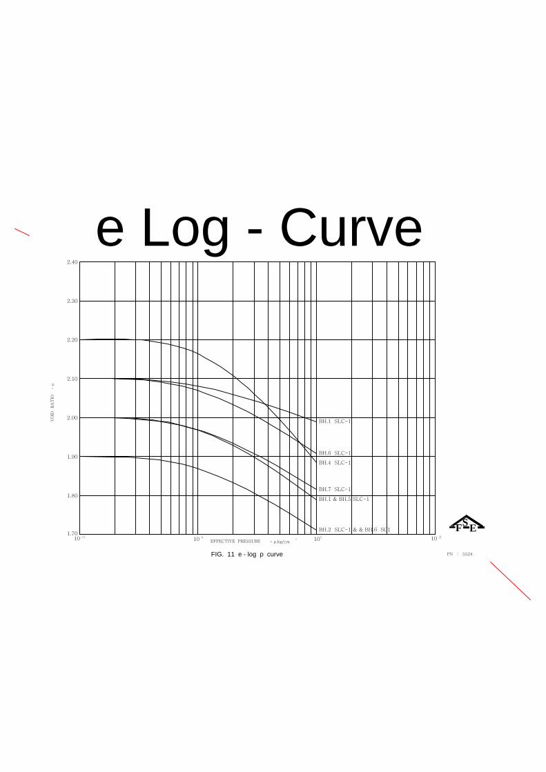
4.9 Consolidation Test
These tests were conducted on the undisturbed samples collected
from the cohesive layers. The values of void ratio and compression index Cc are
given in Table-2. The e-log p curves are given in Figs.11.
5. FOUNDATION ANALYSIS
5.1 Pile Foundation
For the proposed structure shallow foundations are not possible
without ground improvement due to the presence of highly consolidating marine silty
clay ..
Piles could be terminated with 1.5 times the dia of the pile, seated in
the very dense sand layer. The length of pile would therefore vary from 50 to 63 M.
the pile in the layer. with N value over 50..
Piles could be designed as end bearing pile. The end bearing
capacity of the pile could be computed using the formula
Qe = 4 X N x As Tonnes
Where,
N = Standard Penetration Test value
As = Area of cross-section of pile expressed in sq.ft

P.N.5524
5
When the piles are resting in the sand layer with N value over 50, it
could be seen that the structural capacity of the pile which is 50 kg/cm2 would
determine the allowable load.
5.1.1 Negative Drag
The layers upto a depth of nearly 15 M should be considered to be
contributing to negative drag. This could be computed using the formula,
Qn = 2 RC λ L
Where,
R = Radius of the pile
C = Cohesion which could be taken as 0.12 kg/cm2
λ = Adhesive factor taken as 0.9
On an average it could be seen that 15% of the bearing capacity of pile chould be
negative drag. This should be deducted from the allowable pile capacity.
The settlement of the pile foundation would be within 5 % of the pile
dia.
M-20 concrete is recommended for the pile foundation to counteract
the harmful effect of chloride chemicals present in soil and water.
5.2 Foundation for lightly loaded structures pavements and roads:
For lightly loaded structures , pavements, and roads, it is necessary
to give ground improvement to possible depth of about 13 M. This could be achieved
by stone column constructed using rammed system without using bentonite to form
the bore. The initial dia of the rammed bore could be around 60 cms rammed to 90
to 100 cms dia with a C/C spacing 2.5 times the dia. By this method the capacity of
the soil could be increased to 8 times the original capacity which could be taken as
0.1 kg/cm^2 Thus, the improved capacity is 0.8 kg/cm^2 .

P.N.5524
6
6. CONCLUSIONS
1. The area explored has got top top soil of 0.5 M is non-uniform.
The underlying layer upto 3 to 5 M is silty sand/silty clay/sandy clay . . The layer
following upto a depth of 41 to 53 M comprise of highly consolidating marine silty
clay with layer of sand in between at some location. A layer of decayed wood is seen
at two locations at BH-1 at 53 M and BH-3 at 41 M. The layer below is very dense
sand. Water table was met with at 4 to 8 M below ground level at the time of
exploration.
2. For heavily loaded structures pile foundation is recommended
with length of pile of 50 to 63 M, resting the pile in the very dense sand layer, utilizing
the structural capacity of 50 kg/cm^2 less negative drag.
3. For lightly loaded structures, pavements and roads, shallow
foundations can be given with ground improvement as suggested.
4. The settlement of pile foundation would be within 5 % of the pile
dia .
5. M-20 concrete is required for the pile foundation to counteract the
harmful effect of chloride chemicals present in soil and water.
F.S.ENGINEERS PVT.LTD (Dr.A. Verghese Chummar)
NEW NO.98, VELACHERY ROAD Director
GUINDY Dated: Sept 23rd, 2011
CHENNAI – 600 032

28
32
36
40
44
24
20
16
( Grey )
SILTY SAND SLS1
8.00 mts
SSEEFFF.S.ENGINEERS PRIVATE LIMITED
0.50
12
8
STANDARD PENETRATION
END OF BORING
TH
IC
KN
ES
S O
F L
AY
ER
0.50
TOP SOIL TS
DE
PT
H A
T W
HIC
H
U.D.S
SA
MP
LE
S A
RE
D.S
DE
PT
H A
T W
HIC
H
CO
LL
EC
TE
D
IN
" C
MS
"
PE
NE
TR
AT
IO
N
N - V
AL
UE
TE
ST
C
ON
DU
CT
ED
TEST DATA
DE
PT
H B
EL
OW
G
L
4
SO
IL
P
RO
FIL
E
REMARKS : ALL DIMENSIONS ARE IN METRES
DESCRIPTION OF SOIL
>5040
RE
LA
TIV
E D
EN
SIT
Y
10 20
CO
NS
IS
TA
NC
Y
30
OF PENETRATION
REPRESENTATION
GRAPHICAL
RESISTANCE
TYPE OF BORING :
PROJECT :
BORE HOLE NO :
SOIL EXPLORATION AND FOUNDATION DESIGN DIVISION
FIELD BORE LOG
1
ROTARY DRILLING
18.08.11
G.W.L :
DATE OF COMPLETION :
DATE OF COMMENCEMENT :
23.08.11
Fig : 2 P N : 5524
69.00
SOIL INVESTIGATION TO SET UP CONTAINER STATION CUM LOGISTICS
4
48
52
56
60
64
68
3.50
4.00
26.00
29.00
53.00
62.00
69.00
22.00
3.00
24.00
9.00
SILTY CLAY SLC1
( Dark Grey )
SAND S1
( Grey )
( Dark Grey )
SILTY CLAY SLC1
( Grey )
SAND S1
DECAYED WOOD
12.00
9.00
6.00
22.50
31.50
MEDIUM
STIFF
19
14 30
3027.00
24.00
5 3010.50 SOFT
MEDIUM
STIFF
STIFF12
14
7
30
30
30
21.00
18.00
15.00
SOFT
MEDIUM
V.LOOSE
6
2 30
30
307.50
4.50 5
1.50
>50 0 V.DENSE69.00
15
28
48
>50
14
13
12
13
MEDIUM
STIFF
MEDIUM
STIFF
STIFF
STIFF
V.DENSE0>50
66.00
60.00
57.00
54.00
0
30
30
51.00 30
30
30
30
3048.00
45.00
8
12
8
30
30
30
42.00
39.00
36.00
33.00
30.00
13.50 309 STIFF
>5063.00 10
STIFF
STIFF
MEDIUM
DENSE
V.DENSE
V.DENSE
CENTRE FOR " M/s. INKEL INFRASTRUCTURES KERALA LTD " AT VALLARPADAM.

V.DENSE
V.DENSE
V.DENSE
V.DENSE
V.DENSE
MEDIUM7 3013.50
30.00
33.00
36.00
39.00
42.00
30
30
30
17
22
18
45.00
48.00 11
0
30
30
1051.00
13
11
9
54.00
57.00
60.00
V.DENSE
STIFF
STIFF
V.STIFF
V.STIFF
V.STIFF
>50
>50
12
10
>50
>50
>50
>50
1.50
14.50
7.50 30
30
303
3
V.LOOSE
SOFT
V.SOFT
15.00
18.00
21.00
30
30
30
6
7
4SOFT
MEDIUM
MEDIUM
MEDIUM10.50 305
24.00
27.00 30
305
14
MEDIUM
STIFF
6.00
9.00
12.00
SAND S1
( Grey )
( Dark Grey )
SILTY CLAY SLC1
40.00
60.00
44.00
4.00
3.50
56
52
48
4
60.00
P N : 5524Fig : 3
25.08.11
DATE OF COMMENCEMENT :
DATE OF COMPLETION :
G.W.L :
23.08.11
ROTARY DRILLING
2
FIELD BORE LOG
SOIL EXPLORATION AND FOUNDATION DESIGN DIVISION
BORE HOLE NO :
PROJECT :
TYPE OF BORING :
RESISTANCE
GRAPHICAL
REPRESENTATION
OF PENETRATION
30
CO
NS
IS
TA
NC
Y
2010
RE
LA
TIV
E D
EN
SIT
Y
40 >50
DESCRIPTION OF SOIL
REMARKS : ALL DIMENSIONS ARE IN METRES
SO
IL
P
RO
FIL
E
4
DE
PT
H B
EL
OW
G
L
TEST DATA
TE
ST
C
ON
DU
CT
ED
N - V
AL
UE
PE
NE
TR
AT
IO
N
IN
" C
MS
"
CO
LL
EC
TE
D
DE
PT
H A
T W
HIC
H
D.S
SA
MP
LE
S A
RE
U.D.S
DE
PT
H A
T W
HIC
H
TOP SOIL TS
0.50
TH
IC
KN
ES
S O
F L
AY
ER
END OF BORING
STANDARD PENETRATION
8
12
0.50
F.S.ENGINEERS PRIVATE LIMITED
FF EESS
5.00 mts
SILTY SAND SLS1
( Grey )
16
20
24
44
40
36
32
28
CENTRE FOR " M/s. INKEL INFRASTRUCTURES KERALA LTD " AT VALLARPADAM.
SOIL INVESTIGATION TO SET UP CONTAINER STATION CUM LOGISTICS

V.DENSE
V.DENSE
V.DENSE
V.DENSE
V.DENSE
V.DENSE>50 013.50
30.00
33.00
36.00
39.00
42.00
30
30
30
16
14
18
45.00
48.00 0
30
30
30
1251.00
13
11
12
54.00
57.00
60.00
DENSE
V.STIFF
DENSE
V.STIFF
STIFF
STIFF
>50
42
21
31
>50
>50
>50
>50
1.50
34.50
7.50 30
30
304
6
V.LOOSE
MEDIUM
SOFT
15.00
18.00
21.00
30
30
12
14 STIFF
STIFF
V.DENSE10.50 0>50
24.00
27.00 30
309
12
STIFF
STIFF
DECAYED WOOD
SAND S1
( Grey )
SILTY CLAY SLC1
( Dark Grey )
( Grey )
SAND S1
( Dark Grey )
SILTY CLAY SLC1
6.00
27.00
4.00
6.00
60.00
47.00
41.00
14.00
10.00
4.00
3.50
56
52
48
4
60.00
P N : 5524Fig : 4
30.08.11
DATE OF COMMENCEMENT :
DATE OF COMPLETION :
G.W.L :
26.08.11
ROTARY DRILLING
3
FIELD BORE LOG
SOIL EXPLORATION AND FOUNDATION DESIGN DIVISION
BORE HOLE NO :
PROJECT :
TYPE OF BORING :
RESISTANCE
GRAPHICAL
REPRESENTATION
OF PENETRATION
30
CO
NS
IS
TA
NC
Y
2010
RE
LA
TIV
E D
EN
SIT
Y
40 >50
DESCRIPTION OF SOIL
REMARKS : ALL DIMENSIONS ARE IN METRES
SO
IL
P
RO
FIL
E
4
DE
PT
H B
EL
OW
G
L
TEST DATA
TE
ST
C
ON
DU
CT
ED
N - V
AL
UE
PE
NE
TR
AT
IO
N
IN
" C
MS
"
CO
LL
EC
TE
D
DE
PT
H A
T W
HIC
H
D.S
SA
MP
LE
S A
RE
U.D.S
DE
PT
H A
T W
HIC
H
TOP SOIL TS
0.50
TH
IC
KN
ES
S O
F L
AY
ER
END OF BORING
STANDARD PENETRATION
8
12
0.50
F.S.ENGINEERS PRIVATE LIMITED
FF EESS
6.00 mts
SILTY SAND SLS1
( Grey )
16
20
24
44
40
36
32
28
12.00
9.00
6.00 MEDIUM5 30
>50 0V.DENSE
CENTRE FOR " M/s. INKEL INFRASTRUCTURES KERALA LTD " AT VALLARPADAM.
SOIL INVESTIGATION TO SET UP CONTAINER STATION CUM LOGISTICS

STIFF3016
6.00
9.00
12.00
28
32
36
40
44
24
20
16
( Grey )
SILTY SAND SLS1
4.00 mts
SSEEFFF.S.ENGINEERS PRIVATE LIMITED
0.50
12
8
STANDARD PENETRATION
END OF BORING
TH
IC
KN
ES
S O
F L
AY
ER
0.50
TOP SOIL TS
DE
PT
H A
T W
HIC
H
U.D.S
SA
MP
LE
S A
RE
D.S
DE
PT
H A
T W
HIC
H
CO
LL
EC
TE
D
IN
" C
MS
"
PE
NE
TR
AT
IO
N
N - V
AL
UE
TE
ST
C
ON
DU
CT
ED
TEST DATA
DE
PT
H B
EL
OW
G
L
4
SO
IL
P
RO
FIL
E
REMARKS : ALL DIMENSIONS ARE IN METRES
DESCRIPTION OF SOIL
>5040
RE
LA
TIV
E D
EN
SIT
Y
10 20
CO
NS
IS
TA
NC
Y
30
OF PENETRATION
REPRESENTATION
GRAPHICAL
RESISTANCE
TYPE OF BORING :
PROJECT :
BORE HOLE NO :
SOIL EXPLORATION AND FOUNDATION DESIGN DIVISION
FIELD BORE LOG
4
ROTARY DRILLING
02.08.11
G.W.L :
DATE OF COMPLETION :
DATE OF COMMENCEMENT :
05.08.11
Fig : 5 P N : 5524
60.00
4
48
52
56
2.50
3.00
41.00
50.00
60.00
38.00
9.00
( Dark Grey )
SILTY CLAY SLC1
( Brownish Grey )
SAND S1
SANDY CLAY SC1
SOFT
V.STIFF
4
27 30
3027.00
24.00
5 3010.50 MEDIUM
SOFT
MEDIUM6
4
30
30
21.00
18.00
15.00
SOFT
V.SOFT
LOOSE
1
8 30
30
307.50
4.50 3
1.50
>50
>50
>50
>50
>50
9
>50
>50
MEDIUM
MEDIUM
STIFF
V.DENSE
STIFF
V.DENSE
60.00
57.00
54.00
10
8
6
51.00 4
30
0
0
048.00
45.00
8
5
6
30
30
30
42.00
39.00
36.00
33.00
30.00
13.50 305 MEDIUM
V.DENSE
V.DENSE
V.DENSE
V.DENSE
V.DENSE
302V.SOFT
( Grey )
CENTRE FOR " M/s. INKEL INFRASTRUCTURES KERALA LTD " AT VALLARPADAM.
SOIL INVESTIGATION TO SET UP CONTAINER STATION CUM LOGISTICS

V.DENSE
V.DENSE
V.DENSE
V.DENSE
V.DENSE
SOFT4 3013.50
30.00
33.00
36.00
39.00
42.00
30
30
30
7
5
7
45.00
48.00 0
0
0
30
051.00
10
9
7
54.00
57.00
60.00
V.DENSE
STIFF
V.DENSE
MEDIUM
LOOSE
LOOSE
>50
>50
16
>50
>50
>50
>50
>50
1.50
14.50
7.50 30
30
305
2
LOOSE
V.SOFT
V.SOFT
15.00
18.00
21.00
30
30
30
4
1
5 MEDIUM
V.SOFT
V.LOOSE
MEDIUM10.50 306
24.00
27.00 30
305
25
MEDIUM
MEDIUM
3.00
6.00
9.00
12.00
SAND S1
( Brownish Grey )
SILTY CLAY SLC1
( Dark Grey )
( Grey )
SANDY CLAY SC1
( Dark Grey )
SILTY CLAY SLC1
9.00
8.00
22.00
60.00
43.00
34.00
26.00
4.00
3.50
56
52
48
4
60.00
P N : 5524Fig : 6
31.08.11
DATE OF COMMENCEMENT :
DATE OF COMPLETION :
G.W.L :
27.08.11
ROTARY DRILLING
5
FIELD BORE LOG
SOIL EXPLORATION AND FOUNDATION DESIGN DIVISION
BORE HOLE NO :
PROJECT :
TYPE OF BORING :
RESISTANCE
GRAPHICAL
REPRESENTATION
OF PENETRATION
30
CO
NS
IS
TA
NC
Y
2010
RE
LA
TIV
E D
EN
SIT
Y
40 >50
DESCRIPTION OF SOIL
REMARKS : ALL DIMENSIONS ARE IN METRES
SO
IL
P
RO
FIL
E
4
DE
PT
H B
EL
OW
G
L
TEST DATA
TE
ST
C
ON
DU
CT
ED
N - V
AL
UE
PE
NE
TR
AT
IO
N
IN
" C
MS
"
CO
LL
EC
TE
D
DE
PT
H A
T W
HIC
H
D.S
SA
MP
LE
S A
RE
U.D.S
DE
PT
H A
T W
HIC
H
TOP SOIL TS
0.50
TH
IC
KN
ES
S O
F L
AY
ER
END OF BORING
STANDARD PENETRATION
8
12
0.50
F.S.ENGINEERS PRIVATE LIMITED
FF EESS
6.00 mts
SILTY SAND SLS1
( Grey )
16
20
24
44
40
36
32
28
302V.SOFT
CENTRE FOR " M/s. INKEL INFRASTRUCTURES KERALA LTD " AT VALLARPADAM.
SOIL INVESTIGATION TO SET UP CONTAINER STATION CUM LOGISTICS

( Dark Grey )
MEDIUM7 30
V.DENSE
V.DENSE
V.DENSE
V.DENSE
HARD
MEDIUM7 3013.50
30.00
33.00
36.00
39.00
42.00
30
30
30
39
28
32
45.00
48.00 30
0
0
30
051.00
9
10
12
54.00
57.00
60.00
V.DENSE
MEDIUM
HARD
HARD
V.STIFF
HARD
35
>50
6
42
>50
>50
>50
>50
1.50
44.50
7.50 30
30
309
1
MEDIUM
V.SOFT
SOFT
15.00
18.00
21.00
30
30
8
7MEDIUM
MEDIUM
V.SOFT10.50 302
24.00
27.00 30
3013
8
STIFF
MEDIUM
3.00
SANDY CLAY SC1
SAND S1
( Brownish Grey )
SILTY CLAY SLC1
( Dark Grey )
12.00
33.00
60.00
50.00
38.00
5.00
4.50
56
52
48
4
60.00
P N : 5524Fig : 7
26.08.11
DATE OF COMMENCEMENT :
DATE OF COMPLETION :
G.W.L :
19.08.11
ROTARY DRILLING
6
FIELD BORE LOG
SOIL EXPLORATION AND FOUNDATION DESIGN DIVISION
BORE HOLE NO :
PROJECT :
TYPE OF BORING :
RESISTANCE
GRAPHICAL
REPRESENTATION
OF PENETRATION
30
CO
NS
IS
TA
NC
Y
2010
RE
LA
TIV
E D
EN
SIT
Y
40 >50
DESCRIPTION OF SOIL
REMARKS : ALL DIMENSIONS ARE IN METRES
SO
IL
P
RO
FIL
E
4
DE
PT
H B
EL
OW
G
L
TEST DATA
TE
ST
C
ON
DU
CT
ED
N - V
AL
UE
PE
NE
TR
AT
IO
N
IN
" C
MS
"
CO
LL
EC
TE
D
DE
PT
H A
T W
HIC
H
D.S
SA
MP
LE
S A
RE
U.D.S
DE
PT
H A
T W
HIC
H
TOP SOIL TS
0.50
TH
IC
KN
ES
S O
F L
AY
ER
END OF BORING
STANDARD PENETRATION
8
12
0.50
F.S.ENGINEERS PRIVATE LIMITED
FF EESS
5.00 mts
SANDY CLAY SC1
( Grey )
16
20
24
44
40
36
32
28
12.00
9.00
6.002 30
V.SOFT
CENTRE FOR " M/s. INKEL INFRASTRUCTURES KERALA LTD " AT VALLARPADAM.
SOIL INVESTIGATION TO SET UP CONTAINER STATION CUM LOGISTICS

V.SOFT3026.00
9.00
12.00
28
24
20
16
( Grey )
SANDY CLAY SC1
4.00 mts
SSEEFFF.S.ENGINEERS PRIVATE LIMITED
0.50
12
8
STANDARD PENETRATION
END OF BORING
TH
IC
KN
ES
S O
F L
AY
ER
0.50
TOP SOIL TS
DE
PT
H A
T W
HIC
H
U.D.S
SA
MP
LE
S A
RE
D.S
DE
PT
H A
T W
HIC
H
CO
LL
EC
TE
D
IN
" C
MS
"
PE
NE
TR
AT
IO
N
N - V
AL
UE
TE
ST
C
ON
DU
CT
ED
TEST DATA
DE
PT
H B
EL
OW
G
L
4
SO
IL
P
RO
FIL
E
REMARKS : ALL DIMENSIONS ARE IN METRES
DESCRIPTION OF SOIL
>5040
RE
LA
TIV
E D
EN
SIT
Y
10 20
CO
NS
IS
TA
NC
Y
30
OF PENETRATION
REPRESENTATION
GRAPHICAL
RESISTANCE
TYPE OF BORING :
PROJECT :
BORE HOLE NO :
SOIL EXPLORATION AND FOUNDATION DESIGN DIVISION
FIELD BORE LOG
7
ROTARY DRILLING
05.09.11
G.W.L :
DATE OF COMPLETION :
DATE OF COMMENCEMENT :
06.09.11
Fig : 8 P N : 5524
30.00
3.50
4.00
30.00
( Dark Grey )
SILTY CLAY SLC1
3.00
STIFF
STIFF
12
11 30
3027.00
24.00
5 3010.50 MEDIUM
MEDIUM
MEDIUM6
8
30
30
21.00
18.00
15.00
SOFT
MEDIUM
SOFT
5
3 30
30
307.50
4.50 4
1.50
STIFF16 3030.00
13.50 306MEDIUM
305MEDIUM
304 SOFT
307 MEDIUM
305MEDIUM
CENTRE FOR " M/s. INKEL INFRASTRUCTURES KERALA LTD " AT VALLARPADAM.
SOIL INVESTIGATION TO SET UP CONTAINER STATION CUM LOGISTICS

SOFT3 30
STIFF15 30
V.SOFT2 30
13.50
30.00 3010 STIFF
1.50
34.50
7.50 30
30
309
1
STIFF
V.SOFT
SOFT
15.00
18.00
21.00 3024MEDIUM
SOFT10.50 303
24.00
27.00 30
3011
9
MEDIUM
STIFF
SILTY CLAY SLC1
( Dark Grey )
30.00
30.00
P N : 5524Fig : 9
07.09.11
DATE OF COMMENCEMENT :
DATE OF COMPLETION :
G.W.L :
06.09.11
ROTARY DRILLING
8
FIELD BORE LOG
SOIL EXPLORATION AND FOUNDATION DESIGN DIVISION
BORE HOLE NO :
PROJECT :
TYPE OF BORING :
RESISTANCE
GRAPHICAL
REPRESENTATION
OF PENETRATION
30
CO
NS
IS
TA
NC
Y
2010
RE
LA
TIV
E D
EN
SIT
Y
40 >50
DESCRIPTION OF SOIL
REMARKS : ALL DIMENSIONS ARE IN METRES
SO
IL
P
RO
FIL
E
4
DE
PT
H B
EL
OW
G
L
TEST DATA
TE
ST
C
ON
DU
CT
ED
N - V
AL
UE
PE
NE
TR
AT
IO
N
IN
" C
MS
"
CO
LL
EC
TE
D
DE
PT
H A
T W
HIC
H
D.S
SA
MP
LE
S A
RE
U.D.S
DE
PT
H A
T W
HIC
H
TOP SOIL TS
0.50
TH
IC
KN
ES
S O
F L
AY
ER
END OF BORING
STANDARD PENETRATION
8
12
0.50
F.S.ENGINEERS PRIVATE LIMITED
FF EESS
5.00 mts
16
20
24
28
12.00
9.00
6.005 30 MEDIUM
SILTY SAND SLS1
( Grey )
3.00
17.00
6.00
20.00
26.00
( Dark Grey )
SILTY CLAY SLC1
SAND S1
( Grey )
CENTRE FOR " M/s. INKEL INFRASTRUCTURES KERALA LTD " AT VALLARPADAM.
SOIL INVESTIGATION TO SET UP CONTAINER STATION CUM LOGISTICS
e Log - Curve
S
EF
PN : 5524FIG. 11 e - log p curve
1.70
1.80
1.90
2.00
2.10
2.20
2.30
2.40
VO
ID R
AT
IO
10 -1
- e
- p.kg/cmEFFECTIVE PRESSURE2
o10 10
1 10 2
BH.1 SLC-1
BH.1 & BH.5 SLC-1
BH.2 SLC-1 & & BH.6 SC1
BH.4 SLC-1
BH.6 SLC-1
BH.7 SLC-1

0.0
01
0.0
02
0.0
03
0.0
04
0.0
08
0.0
1
0.0
05
0.0
2
0.0
3
0.0
4
0.0
6
0.1
0
0.2
0.3
0.6
0.8
1.0
2.0
3.0
4.0
6.0
8.0
10.0
20.0
30.0
40.0
60.0
80.0
100.0
0
10
20
30
40
50
60
70
80
90
100
PARTICLE SIZE IN mm.
0.0
75
0.1
25
0.2
12
0.4
25
0.7
10
1.1
8
2.3
6
4.7
5
0.4
25
0.0
75
4.7
5
SILT
SAND
MEDIUM
COARSEFINE
GRAVEL
CLAY
FIG. 10 GRAIN SIZE DISTRIBUTION CURVE
PE
RC
EN
T
FIN
ER
Grain size -Curve
EFS
S
1
S
C
1
S
L
C
1
S
L
S
1

Project: Soil Investigation to Set up Containers Station Cum Logistics Centre for “ M/s. InkelInfrastructures Kerala Ltd “ at Vallarpadam.
Sl.No Depth Layer wl wp wnSwell Grain Size Distribution Sp. Gr.
G
Clay Silt Sand Gravel
M % % % % % % % %
1 2 3 4 5 6 7 9 10 11 12 13
BH.1
0.00-0.0.50
0.50-4.00
4.00-26.00
26.00-29.00
29.00-53.00
53.00-62.00
62.00-69.00
BH.2
0.00-0.50
0.50-4.00
4.00-44.00
44.00-60.00
BH.3
0.00-0.50
0.50-4.00
4.00-10.00
10.00-14.00
14.00-41.00
41.00-47.00
47.00-60.00
BH.4
0.00-0.50
0.50-3.00
3.00-41.00
41.00-50.00
50.00-60.00
BH.5
0.00-0.50
0.50-4.00
4.00-26.00
26.00-34.00
34.00-43.00
43.00-60.00
TS
SLS1
SLC1
S1
SLC1
Decayed Wood
S1
TS
SLS1
SLC1
S1
TS
SLS1
SLC1
S1
SLC1
Decayed Wood
S1
TS
SLS1
SLC1
SC1
S1
TS
SLS1
SLC1
SC1
SLC1
S1
-
-
63
-
70
-
-
-
-
68
-
-
-
58
-
69
-
-
-
-
65
45
-
-
-
70
44
65
-
-
-
38
-
36
-
-
-
-
31
-
-
-
32
-
38
-
-
-
-
30
27
-
-
-
40
30
39
-
-
-
41
-
50
-
-
-
-
42
-
-
-
39
-
47
-
-
-
-
43
15
-
-
-
49
15
45
-
-
-
69
-
71
-
-
-
-
66
-
-
-
68
-
66
-
-
-
-
76
42
-
-
-
80
42
75
-
-
3
71
-
74
-
-
-
5
72
-
-
2
70
-
74
-
-
-
4
67
45
-
-
2
65
45
72
-
-
32
29
8
26
-
11
-
35
28
10
-
32
30
12
26
-
9
-
34
33
19
11
-
30
35
15
28
12
-
65
-
92
-
-
89
-
60
-
90
-
66
-
88
-
-
91
-
62
-
24
89
-
68
-
40
-
88
-
-
-
-
-
-
-
-
-
-
-
-
-
-
-
-
-
-
-
-
-
-
-
-
-
-
-
-
-
-
2.65
2.63
2.65
2.63
-
2.65
-
2.65
2.63
2.65
-
2.65
2.63
2.65
2.63
-
2.65
-
2.65
2.63
2.63
2.65
-
2.65
2.63
2.63
2.63
2.65

Sl.No Depth Layer wl wp wnSwell Grain Size Distribution Sp. Gr.
G
Clay Silt Sand Gravel
M % % % % % % % %
1 2 3 4 5 6 7 9 10 11 12 13
BH.6
0.00-0.50
0.50-5.00
5.50-38.00
38.00-50.00
50.00-60.00
BH.7
0.00-0.50
0.50-4.00
4.00-30.00
BH.8
0.00-0.50
0.50-3.00
3.00-20.00
20.00-26.00
26.00-30.00
TS
SC1
SLC1
SC1
S1
TS
SC1
SLC1
TS
SLS1
SLC1
S1
SLC1
-
45
67
43
-
-
45
58
-
-
64
-
70
-
26
37
28
-
-
25
32
-
-
31
-
41
-
15
41
20
-
-
15
44
-
-
44
-
50
-
42
66
42
-
-
42
65
-
-
62
-
80
-
45
69
46
-
-
45
65
-
5
71
-
70
-
12
31
20
9
-
12
35
-
35
29
12
30
-
43
-
34
91
-
43
-
-
60
-
88
-
-
-
-
-
-
-
-
-
-
-
-
-
-
-
2.63
2.63
2.63
2.65
-
2.63
2.63
-
2.65
2.63
2.65
2.63
Table – 1 Laboratory Tests Results PN : 5524

Project: Soil Investigation to Set up Containers Station Cum Logistics Centre for “ M/s. InkelInfrastructures Kerala Ltd “ at Vallarpadam.
Table
–
2
La
Table – 2 Laboratory Tests Results PN : 5524
Bh No Depth Layer UccTest Qu NMC
BulkDensity
DryDensity
ConsolidationTest
Mts Kg/cm2 % gm/cc gm/cc eo Cc
BH-1
BH-2
BH-4
BH-5
BH-6
BH-8
12.00
31.50
12.00
12.00
15.00
3.00
15.00
13.50
SLC1
SLC1
SLC1
SLC1
SLC1
SC1
SLC1
SLC1
0.3
0.5
0.3
0.3
0.3
0.7
0.6
0.1
-
-
-
-
-
-
-
-
1.76
1.84
1.81
1.79
1.85
1.83
1.76
1.79
1.04
1.07
1.09
1.01
1.02
1.28
1.06
1.08
2.10
2.00
1.90
2.20
2.00
2.10
1.90
2.00
0.12
0.21
0.18
0.32
0.21
0.19
0.18
0.18