project manual for apostle islands marina …
TRANSCRIPT

00 01 01-1
PROJECT MANUAL FOR
APOSTLE ISLANDS MARINA
RECONSTRUCTION
CITY OF BAYFIELD
BAYFIELD COUNTY, WI
July 2021
Project #00320024
Prepared By:
MSA Professional Services, Inc.
1230 South Blvd.
Baraboo, WI 53913

THIS PAGE INTENTIONALLY LEFT BLANK

Project #00320024 Seals © 2021 MSA Professional Services, Inc.
00 01 07-1
Apostle Islands Marina Reconstruction City of Bayfield , Bayfield County, WI
Project #00320024
Seals Page
CIVIL ENGINEER:
MSA Professional Services, Inc.
ELECTRICAL ENGINEER:
Muermann Engineering Inc./
Division of MSA Professional
Services, Inc
STRUCTURAL:
MSA Professional Services, Inc.
Krista Russ Kyle

THIS PAGE INTENTIONALLY LEFT BLANK

Project #00320024 Contents and Project Manual Index © 2021 MSA Professional Services, Inc.
00 01 10-1
PROJECT MANUAL FOR
APOSTLE ISLANDS MARINA RECONSTRUCTION
CITY OF BAYFIELD
BAYFIELD COUNTY, WI
CONTENTS AND PROJECT MANUAL INDEX
DESCRIPTION PAGE
DIVISION 00 – PROCUREMENT AND CONTRACTING REQUIREMENTS
Title Page 00 01 01-1
Seals Page 00 01 07-1
Contents and Project Manual Index 00 01 10-1 - 3
Advertisement for Bids 00 11 13-1 - 2
Instructions to Bidders 00 21 13-1 - 11
Available Project Information 00 31 32-1
Bid 00 41 00-1 – 8
Bid Attachment – Potential Conflict of Interest Disclosure Form
Exhibits to Bid
Bid Bond
Appendix F – Davis-Bacon Requirements 00 43 00-1 - 9
Notice of Award 00 51 00-1
Agreement 00 52 00-1 - 8
Notice to Proceed 00 55 00-1
Performance Bond 00 61 13.13-1 - 3
Payment Bond 00 61 13.16-1 - 3
Application for Payment 00 62 76-1 - 3
Field Order 00 63 36-1
Work Change Directive 00 63 49-1
Change Order 00 63 63-1 - 2
Certificate of Substantial Completion 00 65 16-1
Standard General Conditions of the Construction Contract 00 72 00-1 - 68
Supplementary Conditions 00 73 00-1 - 9
Federal Wage Rates 00 73 43-1
Funding Requirements 00 80 00-1 – 4
DIVISION 01 - GENERAL REQUIREMENTS
Section 01 11 00 Summary of Work 01 11 00 - 1
Section 01 31 19 Project Meetings 01 31 19 - 1
Section 01 32 16 Construction Progress Schedule 01 32 16 - 1 - 3
Section 01 32 23 Survey and Layout Data 01 32 23 - 1
Section 01 33 00 Submittals 01 33 00 - 1 - 3
Section 01 33 23 Shop Drawings, Product Data, and Samples
(Submittal Log)
01 33 23 - 1 - 2

Project #00320024 Contents and Project Manual Index © 2021 MSA Professional Services, Inc.
00 01 10-2
Section 01 41 26 Permits 01 41 26 - 1
Section 01 45 16.11 Concrete Quality Control 01 45 16.11 - 1 - 6
Section 01 56 39 Tree Protection 01 56 39 - 1 - 3
Section 01 77 00 Closeout Procedures 01 77 00 - 1 - 3
DIVISION 02 - EXISTING CONDITIONS
Section 02 01 00 Maintenance of Existing Conditions 02 01 00 - 1
Section 02 41 16 Structure Demolition 02 41 16 - 1 - 5
DIVISION 03 - CONCRETE
Section 03 20 00 Concrete Reinforcing 03 20 00 - 1 - 5
Section 03 30 00 Cast-In-Place Concrete 03 30 00 - 1 - 22
DIVISION 05 - METALS
Section 05 12 00 Structural Steel 05 12 00 - 1 - 4
DIVISION 06 – WOOD, PLASTICS, AND COMPOSITES
Section 06 10 00 Rough Carpentry 06 10 00 - 1 - 4
Section 06 15 00 Wood Decking 06 15 00 - 1 - 3
DIVISION 22 - PLUMBING
Section 22 11 00 Plumbing 22 11 00 - 1 - 3
DIVISION 26 - ELECTRICAL
Section 26 05 00 Electrical Contract Requirements 26 05 00 - 1 - 12
Section 26 05 01 Electrical Demolition 26 05 01 - 1 - 5
Section 26 05 04 Documentation 26 05 04 - 1 - 2
Section 26 05 19 Wire and Cable 26 05 19 - 1 - 8
Section 26 05 26 Grounding and Bonding for Electrical
Systems
26 05 26 - 1 - 5
Section 26 05 29 Supporting Devices 26 05 29 - 1 - 4
Section 26 05 34 Conduit 26 05 34 - 1 - 7
Section 26 05 53 Electrical Identification 26 05 37 - 1 - 4
Section 26 24 16 Panelboards 26 24 16 - 1 - 8
Section 26 24 17 Dockside Utility Centers 26 24 17 - 1 - 3
Section 26 56 29 Exterior Lighting Fixtures 26 56 29 - 1 - 7

Project #00320024 Contents and Project Manual Index © 2021 MSA Professional Services, Inc.
00 01 10-3
DIVISION 31 - EARTHWORK
Section 31 05 19.13 Geosynthetics for Earthwork 31 05 19.13 - 1 - 5
Section 31 11 00 Clearing and Grubbing 31 11 00 - 1 - 3
Section 31 23 23.01 Granular Fill 31 23 23.14 - 1 - 2
Section 31 25 00 Erosion and Sedimentation Controls 31 25 00 - 1 - 23
Section 31 37 00 Riprap 31 37 00 - 1 - 10
Section 31 41 16 Steel Sheet Piling 31 41 16 - 1 - 4
Section 31 62 16.16 Steel HP Piles 31 62 16.16 - 1 - 4
DIVISION 32 - EXTERIOR IMPROVEMENTS
Section 32 11 23 Aggregate Base and Subbase 32 11 23 - 1 - 4
Section 32 12 16 Asphaltic Concrete Pavement 32 12 16 - 1 - 5
Section 32 13 10 Concrete Sidewalk, Steps and Driveways 32 13 10 - 1 - 5
Section 32 91 19.13 Topsoil Placement and Grading 32 91 19.13 - 1 - 6
Section 32 92 19 Seeding 32 92 19 - 1 - 6
DIVISION 33 - UTILITIES
Section 33 41 13 Public Storm Utility Drainage Piping 33 41 13 - 1 - 6
APPENDICES
Appendix A Technical Standards
Appendix B Soil Sampling

THIS PAGE INTENTIONALLY LEFT BLANK

Project #00320024 Advertisement for Bids © 2021 MSA Professional Services, Inc.
00 11 13-1
ADVERTISEMENT FOR BIDS
APOSTLE ISLANDS MARINA RECONSTRUCTION
CITY OF BAYFIELD
BAYFIELD COUNTY, WI
The City of Bayfield will receive and accept bids ONLY through QuestCDN.com via the online
electronic bid service (QuestCDN) for the construction of Apostle Islands Marina Reconstruction
until July 30, 2021 at 2:00 PM CDT. All bids will be downloaded and publicly read aloud during a
virtual public bid opening that will be held at the day and time of the bid closing. All planholders
will receive information via Quest on how to join the virtual meeting prior to the bid opening.
A pre-Bid conference will be held virtually at 10:00 AM CDT on July 21, 2021. All planholders will
receive information via Quest on how to join the virtual meeting prior to the pre-bid conference.
Representatives of OWNER and ENGINEER will be present to discuss the Project. Bidders are
encouraged to attend and participate in the conference.
The work for which bids are asked includes approximately 295 lineal feet of improvements along A-
Dock including removals, excavation, steel sheet piling, concrete walkway, water and electrical
services; approximately 410 lineal feet of improvements along East Breakwall including removals,
stone revetment, geotextile fabric, storm sewer pipe through revetment/existing timber cribs, steel
sheet piling, timber walkway, water and electrical services; approximately 630 lineal feet of
improvements along South Shoreline including removals, excavation, stone revetment and geotextile
fabric; work also includes, but not limited to, clearing vegetation, parking lot patching, turf
restoration, lighting relocations, removal and replacement of dock fingers.
The anticipated substantial completion date is April 15, 2022 and final completion date is April 30,
2022. Planholders list will be updated interactively on our web address at http://www.msa-ps.com
under Bidding.
Copies of the BIDDING DOCUMENTS are available at www.questcdn.com. QuestCDN Vbid
system requires Bidders to purchase BIDDING DOCUMENTS from QuestCDN. You may
download the digital plan documents for $40 by inputting Quest eBidDoc #7888268 on the website’s
Project Search page. Please contact QuestCDN.com at 952-233-1632 or [email protected] for
assistance in free membership registration, downloading, and working with the digital project
information.
No proposal will be accepted unless accompanied by a certified check or bid bond equal to at least
5% of the amount bid, payable to the OWNER as a guarantee that, if the bid is accepted, the bidder
will execute and file the proper contract and bond within 15 days after the award of the contract.
BIDDER is required to deliver the original certified check or bid bond within the 72 hours of bid
opening to MSA Professional Services, Inc., Attn: Krista Sommerfeldt, 1230 South Blvd., Baraboo,
WI 53913. The certified check or bid bond will be returned to the bidder as soon as the contract is
signed, and if after 15 days the bidder shall fail to do so, the certified check or bid bond shall be
forfeited to the OWNER as liquidated damages.
No bid may be withdrawn within 60 days after the actual date of the opening thereof.

Project #00320024 Advertisement for Bids © 2021 MSA Professional Services, Inc.
00 11 13-2
The minimum wage rate and fringe benefit requirements to be paid on the project shall be in
accordance with federal Davis-Bacon and Related Acts. Federal wage requirements can be found at
https://beta.sam.gov/search?index=wd. Be aware that project Administrators, Bidders, and
Contractors are required to use the latest federal wage decision available at the time of bid opening.
Federal USACE Section 154 funds, State of Wisconsin Harbor Assistance Program (HAP) funds and
local funds are being used for this project.
OWNER reserves the right to waive any informalities or to reject any or all bids.
Published by the authority of the City of Bayfield , Wisconsin.
CONSULTING ENGINEER:
MSA Professional Services, Inc.
1230 South Blvd.
Baraboo, WI 53913
Krista Sommerfeldt, P.E.
(608) 355-8924

Project #00320024 Instructions to Bidders © 2021 MSA Professional Services, Inc.
00 21 13-1
INSTRUCTIONS TO BIDDERS TABLE OF ARTICLES
Article Article Number 1 Defined Terms 2 Copies of Bidding Documents 3 Qualifications of Bidders 4 Examination of Bidding Documents, Other Related Data and Site 5 Pre-Bid Conference 6 Site and Other Areas 7 Interpretations and Addenda 8 Bid Security 9 Contract Times 10 Liquidated Damages 11 Substitute and “Or-equal” Items 12 Subcontractors, Suppliers and Others 13 Preparation of Form 14 Basis of Bid; Comparison of Bids 15 Submittal of Bid 16 Modification and Withdrawal of Bid 17 Opening of Bids 18 Bids to Remain Subject to Acceptance 19 Evaluation of Bids and Award of Contract 20 Contract Security and Insurance 21 Signing of Agreement 22 Sales and Use Taxes 23 Retainage

Project #00320024 Instructions to Bidders © 2021 MSA Professional Services, Inc.
00 21 13-2
INSTRUCTIONS TO BIDDERS
ARTICLE 1 - DEFINED TERMS
1.01 Terms used in these Instructions to Bidders will have the meanings indicated in the General
Conditions and Supplementary Conditions. Additional terms used in these Instructions to
Bidders have the meanings indicated below:
A. BIDDER - The individual or entity who submits a Bid directly to OWNER.
B. Issuing Office - The office from which the Bidding Documents are to be issued and
where the bidding procedures are to be administered.
C. Successful BIDDER - The lowest responsible BIDDER submitting a responsive Bid
to whom OWNER (on the basis of OWNER’s evaluation as hereinafter provided)
makes an award.
ARTICLE 2 - COPIES OF BIDDING DOCUMENTS
2.01 Complete sets of the Bidding Documents in the number and for the fee, if any, stated in the
Advertisement or Invitation to Bid may be obtained from the Quest CDN.
2.02 QuestCDN Vbid system requires BIDDERS to purchase bidding documents from
QuestCDN. If bid documents are not purchased through QuestCDN, the Vbid system will
not allow Bid submission.
2.03 Complete sets of Bidding Documents must be used in preparing Bids; neither OWNER nor
ENGINEER assumes any responsibility for errors or misinterpretations resulting from the
use of incomplete sets of Bidding Documents.
2.04 OWNER and ENGINEER, in making copies of Bidding Documents available on the above
terms, do so only for the purpose of obtaining Bids for the Work and do not confer a license
or grant for any other use.
ARTICLE 3 - QUALIFICATIONS OF BIDDERS
3.01 To demonstrate BIDDER’s qualifications to perform the Work, within five days of
OWNER’s request, BIDDER shall submit written evidence such as financial data, previous
experience, present commitments, and other such data as may be called for below.
A. Each Bid must contain evidence of BIDDER’s qualification to do business in the
state where the project is located or covenant to obtain such qualification prior to
award of the contract.
B. No contractor or subcontractor may work on this project who is currently debarred
federally or in the State of Wisconsin.

Project #00320024 Instructions to Bidders © 2021 MSA Professional Services, Inc.
00 21 13-3
C. BIDDER’s state contractor license number, if applicable.
3.02 BIDDER is advised to carefully review those portions of the Bid Form requiring BIDDER’s
representations and certifications.
ARTICLE 4 - EXAMINATION OF BIDDING DOCUMENTS, OTHER RELATED DATA
AND SITE
4.01 Subsurface and Physical Conditions
A. The Supplementary Conditions identify:
1. Those reports of explorations and tests of subsurface conditions at or
contiguous to the Site.
2. Those drawings known to OWNER of physical conditions relating to existing
surface or subsurface structures at the Site (except Underground Facilities).
B. Copies of reports and drawings referenced in Paragraph 4.01.A will be made
available by OWNER to any BIDDER on request. Those reports and drawings are
not part of the Contract Documents, but the “technical data” contained therein upon
which BIDDER is entitled to rely as provided in Paragraph 4.02 of the General
Conditions has been identified and established in Paragraph 4.02 of the
Supplementary Conditions. BIDDER is responsible for any interpretation or
conclusion BIDDER draws from any “technical data” or any other data,
interpretations, opinions or information contained in such reports or shown or
indicated in such drawings.
4.02 Underground Facilities
A. Information and data shown or indicated in the Bidding Documents with respect to
existing Underground Facilities at or contiguous to the Site is based upon
information and data furnished to OWNER and ENGINEER by owners of such
Underground Facilities, including OWNER, or others.
4.03 Provisions concerning responsibilities for the adequacy of data furnished to prospective
Bidders with respect to subsurface conditions, or physical conditions and Underground
Facilities, and possible changes in the Bidding Documents due to differing or unanticipated
subsurface or physical conditions appear in Paragraphs 4.02, 4.03, and 4.04 of the General
Conditions. Provisions concerning responsibilities for the adequacy of data furnished to
prospective Bidders with respect to a Hazardous Environmental Condition at the Site, if any,
and possible changes in the Contract Documents due to any Hazardous Environmental
Condition uncovered or revealed at the Site which was not shown or indicated in the
Drawings or Specifications or identified in the Contract Documents to be within the scope of
the Work appear in Paragraph 4.06 of the General Conditions.

Project #00320024 Instructions to Bidders © 2021 MSA Professional Services, Inc.
00 21 13-4
4.04 On request, OWNER will provide BIDDER access to the Site to conduct such examinations,
investigations, explorations, tests and studies as BIDDER deems necessary for submission of
a Bid. BIDDER shall fill all holes and clean up and restore the Site to its former condition
upon completion of such explorations, investigations, tests and studies. BIDDER shall
comply with all applicable Laws and Regulations relative to excavation and utility locates.
4.05 Reference is made to Article 7 of the Supplementary Conditions for the identification of the
general nature of other work that is to be performed at the Site by OWNER or others (such as
utilities and other prime contractors) that relates to the Work contemplated by these Bidding
Documents. On request, OWNER will provide to each BIDDER for examination access to or
copies of contract documents (other than portions thereof related to price) for such other
work.
A. Paragraph 6.13.C of the General Conditions indicates that if an OWNER safety
program exists, it will be noted in the Supplementary Conditions.
4.06 It is the responsibility of each BIDDER before submitting a Bid to:
A. examine and carefully study the Bidding Documents, and the other related data
identified in the Bidding Documents.
B. visit the Site and become familiar with and satisfy BIDDER as to the general, local,
and Site conditions that may affect cost, progress, and performance of the Work.
C. become familiar with and satisfy BIDDER as to all federal, state, and local Laws and
Regulations that may affect cost, progress, and performance of the Work.
D. carefully study all: (1) reports of explorations and tests of subsurface conditions at or
contiguous to the Site and all drawings of physical conditions relating to existing
surface or subsurface structures at the Site (except Underground Facilities) that have
been identified in Paragraph 4.02 of the Supplementary Conditions as containing
reliable "technical data," and (2) reports and drawings of Hazardous Environmental
Conditions, if any, at the Site that have been identified in the Paragraph 4.06 of the
Supplementary Conditions as containing reliable "technical data".
E. BIDDER has considered the information known to BIDDER; information commonly
known to contractors doing business in the locality of the Site; information and
observations obtained from visits to the Site; the Bidding Documents; and the Site-
related reports and drawings identified in the Bidding Documents, with respect to the
effect of such information, observations, and documents on (1) the cost, progress,
and performance of the Work; (2) the means, methods, techniques, sequences, and
procedures of construction to be employed by BIDDER, including applying the
specific means, methods, techniques, sequences, and procedures of construction
expressly required by the Bidding Documents; and (3) BIDDER’s safety precautions
and programs.

Project #00320024 Instructions to Bidders © 2021 MSA Professional Services, Inc.
00 21 13-5
F. agree at the time of submitting its Bid that no further examinations, investigations,
explorations, tests, studies, or data are necessary for the determination of its Bid for
performance of the Work at the price(s) bid and within the times required, and in
accordance with the other terms and conditions of the Bidding Documents.
G. become aware of the general nature of the work to be performed by OWNER and
others at the Site that relates to the Work as indicated in the Bidding Documents.
H. promptly give ENGINEER written notice of all conflicts, errors, ambiguities, or
discrepancies that BIDDER discovers in the Bidding Documents and confirm that the
written resolution thereof by ENGINEER is acceptable to BIDDER; and
I. determine that the Bidding Documents are generally sufficient to indicate and convey
understanding of all terms and conditions for the performance of the Work.
4.07 The submission of a Bid will constitute an incontrovertible representation by BIDDER that
BIDDER has complied with every requirement of this Article 4, that without exception the
Bid is premised upon performing and furnishing the Work required by the Bidding
Documents and applying any specific means, methods, techniques, sequences, and
procedures of construction that may be shown or indicated or expressly required by the
Bidding Documents, that BIDDER has given ENGINEER written notice of all conflicts,
errors, ambiguities, and discrepancies that BIDDER has discovered in the Bidding
Documents and the written resolutions thereof by ENGINEER are acceptable to BIDDER,
and that the Bidding Documents are generally sufficient to indicate and convey
understanding of all terms and conditions for performing and furnishing the Work.
ARTICLE 5 - PRE-BID CONFERENCE
5.01 A pre-Bid conference will be held virtually at 10:00 AM CDT on July 21, 2021. All
planholders will receive information via Quest on how to join the virtual meeting prior to the
pre-bid conference. Representatives of OWNER and ENGINEER will be present to discuss
the Project. BIDDERs are encouraged to attend and participate in the conference.
ENGINEER will transmit to all prospective Bidders of record such Addenda as ENGINEER
considers necessary in response to questions arising at the conference. Oral statements may
not be relied upon and will not be binding or legally effective.
ARTICLE 6 - SITE AND OTHER AREAS
6.01 The Site is identified in the Bidding Documents. Easements for permanent structures or
permanent changes in existing facilities are to be obtained and paid for by OWNER unless
otherwise provided in the Bidding Documents. All additional lands and access thereto
required for temporary construction facilities, construction equipment or storage of materials
and equipment to be incorporated in the Work are to be obtained and paid for by
CONTRACTOR.

Project #00320024 Instructions to Bidders © 2021 MSA Professional Services, Inc.
00 21 13-6
ARTICLE 7 - INTERPRETATIONS AND ADDENDA
7.01 All questions about the meaning or intent of the Bidding Documents are to be submitted to
ENGINEER in writing. Interpretations or clarifications considered necessary by
ENGINEER in response to such questions will be issued by Addenda mailed or delivered to
all parties recorded by ENGINEER as having received the Bidding Documents. Questions
received less than ten days prior to the date for opening of Bids may not be answered. Only
questions answered by Addenda will be binding. Oral and other interpretations or
clarifications will be without legal effect.
7.02 Addenda may be issued to clarify, correct, or change the Bidding Documents as deemed
advisable by OWNER or ENGINEER.
ARTICLE 8 - BID SECURITY
8.01 A Bid must be accompanied by Bid security made payable to OWNER in an amount of 5%
of BIDDER’s maximum Bid price and in the form of a certified check, Surety2000 Bid Bond
(OWNER must be registered with Surety2000 in order to accept) or an electronic Bid Bond
issued by a surety meeting the requirements of Paragraph 5.01 and 5.02 of the General
Conditions. BIDDER is required to deliver the original certified check or bid bond within the
72 hours of bid opening to MSA Professional Services, Inc., Attn: Krista Sommerfeldt, 1230
South Blvd., Baraboo, WI 53913.
8.02 The Bid security of Successful BIDDER will be retained until such BIDDER has executed
the Contract Documents, furnished the required contract security and met the other
conditions of the Notice of Award, whereupon the Bid security will be returned. If the
Successful BIDDER fails to execute and deliver the Contract Documents and furnish the
required contract security within 15 days after the Notice of Award, OWNER may consider
BIDDER to be in default, annul the Notice of Award, and the Bid security of that BIDDER
will be forfeited. The Bid security of other Bidders whom OWNER believes to have a
reasonable chance of receiving the award may be retained by OWNER until the earlier of
seven days after the Effective Date of the Agreement or 61 days after the Bid opening,
whereupon Bid security furnished by such Bidders will be returned.
8.03 Bid security of other Bidders whom OWNER believes do not have a reasonable chance of
receiving the award will be returned within seven days after the Bid opening.
ARTICLE 9 - CONTRACT TIMES
9.01 The number of days within which, or the dates by which, Milestones are to be achieved and
the Work is to be substantially completed and ready for final payment are set forth in the
Agreement.
ARTICLE 10 - LIQUIDATED DAMAGES
10.01 Provisions for liquidated damages, if any, are set forth in the Agreement.

Project #00320024 Instructions to Bidders © 2021 MSA Professional Services, Inc.
00 21 13-7
ARTICLE 11 - SUBSTITUTE AND “OR-EQUAL” ITEMS
11.01 The Contract, if awarded, will be on the basis of materials and equipment specified or
described in the Bidding Documents without consideration of possible substitute or “or-
equal” items. Whenever it is specified or described in the Bidding Documents that a
substitute or “or-equal” item of material or equipment may be furnished or used by
CONTRACTOR if acceptable to ENGINEER, application for such acceptance will not be
considered by ENGINEER until after the Effective Date of the Agreement.
ARTICLE 12 - SUBCONTRACTORS, SUPPLIERS AND OTHERS
12.01 If the Supplementary Conditions require the identity of certain Subcontractors, Suppliers,
individuals, or entities to be submitted to OWNER in advance of a specified date prior to the
Effective Date of the Agreement, the apparent Successful BIDDER, and any other BIDDER
so requested, shall within five days after Bid opening, submit to OWNER a list of all such
Subcontractors, Suppliers, individuals, or entities proposed for those portions of the Work
for which such identification is required. Such list shall be accompanied by an experience
statement with pertinent information regarding similar projects and other evidence of
qualification for each such Subcontractor, Supplier, individual, or entity if requested by
OWNER. If OWNER or ENGINEER, after due investigation, has reasonable objection to
any proposed Subcontractor, Supplier, individual, or entity, OWNER may, before the Notice
of Award is given, request apparent Successful BIDDER to submit a substitute.
12.02 If apparent Successful BIDDER declines to make any such substitution, OWNER may award
the Contract to the next lowest BIDDER that proposes to use acceptable Subcontractors,
Suppliers, individuals, or entities. Declining to make requested substitutions will not
constitute grounds for forfeiture of the Bid security of any BIDDER. Any Subcontractor,
Supplier, individual, or entity so listed and against which OWNER or ENGINEER makes no
written objection prior to the giving of the Notice of Award will be deemed acceptable to
OWNER and ENGINEER subject to revocation of such acceptance after the Effective Date
of the Agreement as provided in Paragraph 6.06 of the General Conditions.
12.03 CONTRACTOR shall not be required to employ any Subcontractor, Supplier, individual, or
entity against whom CONTRACTOR has reasonable objection.
ARTICLE 13 - PREPARATION OF FORM
13.01 The Bid Form is included with the Bidding Documents.
13.02 All blanks on the Bid form shall be completed and submitted via QUESTvBID.
13.03 A Bid by a corporation shall be executed in the corporate name by the president or a vice-
president or other corporate officer accompanied by evidence of authority to sign. The
corporate seal shall be affixed and attested by the secretary or an assistant secretary. The
corporate address and state of incorporation shall be provided on the Bid Form.

Project #00320024 Instructions to Bidders © 2021 MSA Professional Services, Inc.
00 21 13-8
13.04 A Bid by a partnership shall be executed in the partnership name and signed by a partner,
(whose title must appear under the signature), accompanied by evidence of authority to sign.
The official address of the partnership shall be shown.
13.05 A Bid by a limited liability company shall be executed in the name of the firm by a member
and accompanied by evidence of authority to sign. The state of formation of the firm and the
official address of the firm shall be shown.
13.06 A Bid by an individual shall show the BIDDER’s name and official address.
13.07 A Bid by a joint venture shall be executed by each joint venturer in the manner indicated on
the Bid form. The official address of the joint venture must be provided on the Bid Form.
13.08 All names shall be printed in ink below the signatures.
13.09 The Bid shall contain an acknowledgment of receipt of all Addenda, the numbers of which
shall be filled in on the Bid Form.
13.10 Postal and e-mail address and telephone number for communications regarding the Bid shall
be shown.
13.11 The Bid shall contain evidence of BIDDER’s authority and qualification to do business in
the state or locality where the Project is located, or BIDDER shall covenant in writing to
obtain such qualification prior to award of the Contract and attach such covenant to the Bid.
BIDDER’s state contractor license number, if any, shall also be shown on the Bid Form.
ARTICLE 14 - BASIS OF BID; COMPARISON OF BIDS
14.01 BIDDERs shall submit a Bid on a lump sum and/or unit price basis for each item of Work
listed in the Bid schedule.
A. The total of all estimated prices will be the sum of the products of the estimated
quantity of each item and the corresponding unit price. The final quantities and
Contract Price will be determined in accordance with Paragraph 11.03 of the General
Conditions.
B. Discrepancies between the multiplication of units of Work and unit prices will be
resolved in favor of the unit prices. Discrepancies between the indicate sum of any
column of figures and the correct sum thereof will be resolved in favor of the correct
sum. Discrepancies between word and figures will be resolved in favor of the words.
C. All public construction, the estimated cost of which exceeds $25,000, shall be let by
contract to the lowest responsible bidder; all other public construction shall be let as
the council may direct. (See Wis. Stat. § 62.15(1).)

Project #00320024 Instructions to Bidders © 2021 MSA Professional Services, Inc.
00 21 13-9
ARTICLE 15 - SUBMITTAL OF BID
15.01 A Bid shall be submitted no later than the date and time prescribed and at the place indicated
in the Advertisement for Bid or Invitation to Bid and shall be accompanied by the Bid
security and other required documents. Bids will ONLY be received and accepted via the
online electronic bid service through QUESTCDN (www.QuestCDN.com). To access the
electronic bid form, download the project documents and click the online bidding button at
the top of the advertisement. If you need further assistance, please feel free to contact
QuestCDN at (952)-233-1632.
ARTICLE 16 - MODIFICATION AND WITHDRAWAL OF BID
16.01 A Bid may be modified or withdrawn by an appropriate document duly executed in the same
manner that a Bid must be executed and delivered to the place where Bids are to be
submitted prior to the date and time for the opening of Bids.
16.02 If within 24 hours after Bids are opened, any BIDDER files a duly signed written notice with
OWNER and promptly thereafter demonstrates to the reasonable satisfaction of OWNER
that there was a material and substantial mistake in the preparation of its Bid, that BIDDER
may withdraw its Bid, and the Bid security will be returned. Thereafter, if the Work is rebid,
that BIDDER will be disqualified from further bidding on the Work.
ARTICLE 17 - OPENING OF BIDS
17.01 Bids will be opened at the time and place indicated in the Advertisement for Bid or Invitation
to Bid and, unless obviously nonresponsive, read aloud publicly. An abstract of the amounts
of the base Bids and major alternates, if any, will be made available to Bidders after the
opening of Bids.
ARTICLE 18 - BIDS TO REMAIN SUBJECT TO ACCEPTANCE
18.01 All Bids will remain subject to acceptance for the period of time stated in the Bid form, but
OWNER may, in its sole discretion, release any Bid and return the Bid security prior to the
end of this period.
ARTICLE 19 - EVALUATION OF BIDS AND AWARD OF CONTRACT
19.01 OWNER reserves the right to reject any or all Bids, including without limitation,
nonconforming, nonresponsive, unbalanced, or conditional Bids. OWNER further reserves
the right to reject the Bid of any BIDDER whom it finds, after reasonable inquiry and
evaluation, to not be responsible. OWNER may also reject the Bid of any BIDDER if
OWNER believes that it would not be in the best interest of the Project to make an award to
that BIDDER. OWNER also reserves the right to waive all informalities not involving price,
time, or changes in the Work and to negotiate contract terms with the Successful BIDDER.
19.02 More than one Bid for the same Work from an individual or entity under the same or
different names will not be considered. Reasonable grounds for believing that any BIDDER

Project #00320024 Instructions to Bidders © 2021 MSA Professional Services, Inc.
00 21 13-10
has an interest in more than one Bid for the Work may be cause for disqualification of that
BIDDER and the rejection of all Bids in which that BIDDER has an interest.
19.03 In evaluating Bids, OWNER will consider whether or not the Bids comply with the
prescribed requirements, and such alternates, unit prices and other data, as may be requested
in the Bid form or prior to the Notice of Award.
19.04 In evaluating Bidders, OWNER will consider the qualifications of Bidders and may consider
the qualifications and experience of Subcontractors, Suppliers, and other individuals or
entities proposed for those portions of the Work for which the identity of Subcontractors,
Suppliers, and other individuals or entities must be submitted as provided in the
Supplementary Conditions.
19.05 OWNER may conduct such investigations as OWNER deems necessary to establish the
responsibility, qualifications, and financial ability of Bidders, proposed Subcontractors,
Suppliers, individuals, or entities to proposed for those portions of the Work in accordance
with the Contract Documents.
19.06 If the Contract is to be awarded, OWNER will award the Contract to the BIDDER whose
Bid is in the best interests of the project and determined to be the lowest responsive,
responsible bidder.
ARTICLE 20 - CONTRACT SECURITY AND INSURANCE
20.01 Article 5 of the General Conditions, as may be modified by the Supplementary Conditions,
sets forth OWNER’s requirements as to performance and payment Bonds and insurance.
When the Successful BIDDER delivers the executed Agreement to OWNER, it shall be
accompanied by such bonds.
ARTICLE 21 - SIGNING OF AGREEMENT
21.01 When OWNER issues a Notice of Award to the Successful BIDDER, it shall be
accompanied by the required number of unsigned counterparts of the Agreement along with
all the other Contract Documents which are identified in the Agreement as attached thereto.
Within 15 days thereafter, Successful BIDDER shall sign and deliver the required number of
counterparts of the Agreement and attached documents to OWNER. Within 10 days
thereafter, OWNER shall deliver one fully signed counterpart to Successful BIDDER with a
complete set of the Drawings with appropriate identification.
ARTICLE 22 - SALES AND USE TAXES
22.01 OWNER represents that it is a qualifying exempt entity under Section 77.54(9m), Wis. Stats.
(as created by 2015 Wis. Act 126) with respect to exemption from Wisconsin sales and use
tax of certain items that become part of eligible facilities owned by the qualifying exempt
entity. The Bid shall account for such sales and use tax exemptions, to the extent applicable.
The Contract will provide that the CONTRACTOR is not entitled to an increase in Contract
Price if CONTRACTOR is not successful in obtaining an anticipated sales and use tax

Project #00320024 Instructions to Bidders © 2021 MSA Professional Services, Inc.
00 21 13-11
exemption, unless the reason for the inability to obtain the anticipated exemption is a formal
determination by the State of Wisconsin that OWNER is not a qualifying exempt entity.
ARTICLE 23 - RETAINAGE
23.01 Provisions concerning CONTRACTORS’ rights to deposit securities in lieu of retainage
are set forth in the Agreement.

THIS PAGE INTENTIONALLY LEFT BLANK

Project #00320024 Available Project Information © 2021 MSA Professional Services, Inc.
00 31 32-1
AVAILABLE PROJECT INFORMATION

THIS PAGE INTENTIONALLY LEFT BLANK

CONSULTANTS • ENVIRONMENTAL • GEOTECHNICAL • MATERIALS • FORENSICS
www.amengtest.com
REPORT OF GEOTECHNICAL EXPLORATION Breakwater Improvements Bayfield, Wisconsin
AET No. 01-20811
Date: August 28, 2020 Prepared for: City of Bayfield 125 South 1st Street PO Box 1170 Bayfield, WI 54814

Page i
550 Cleveland Avenue North St. Paul, MN 55114 Phone 651-659-9001 Toll Free 800-972-6364 Fax 651-659-1379 www.amengtest.com AA/EEO
This document shall not be reproduced, except in full, without written approval from American Engineering Testing, Inc.
August 28, 2020 City of Bayfield 125 South 1st Street PO Box 1170 Bayfield, WI 54814 Attn: Ms. Billie Hoopman, City Clerk RE: Report of Geotechnical Exploration Breakwater Improvements Bayfield, WI AET No. 01-20811 Dear: Ms. Hoopman American Engineering Testing, Inc. (AET) is pleased to present the results of our subsurface exploration program and geotechnical engineering review for your breakwater improvements project in Bayfield. These services were performed according to our proposal to you dated April 22, 2020. We are submitting one copy of the report to you. Additional copies are being sent on your behalf as noted below. Please contact me if you have any questions about the report. Sincerely, American Engineering Testing, Inc. William K. Cody, PE (MN) Principal Engineer Phone: (651) 603-6606 [email protected] cc: Kyle Busch – MSA Professional Services
Report of Geotechnical Exploration Breakwater Improvements; Bayfield, WI AMERICANAugust 28, 2020 ENGINEERINGReport No. 01-20811 TESTING, INC.
Copyright 2020 American Engineering Testing, Inc.All Rights Reserved
Unauthorized use or copying of this document is strictly prohibited by anyone other than the client for the specific project.
Page ii
SIGNATURE PAGE
Prepared for: Prepared by:
City of Bayfield American Engineering Testing, Inc.125 South 1st Street 550 Cleveland Avenue North Bayfield, WI 54814 St. Paul, Minnesota 55114 (651) 659-9001/www.amengtest.com Attn: Ms. Billie Hoopman, City Clerk
Authored by: Reviewed by:
William K. Cody, PE (MN) Benjamin B. Mattson, PE Principal Engineer Senior Geotechnical Engineer
B j i B M tt PE
8-28-2020

Page iii
TABLE OF CONTENTS
Transmittal Letter............................................................................................................................. i Signature Page ................................................................................................................................ ii TABLE OF CONTENTS ............................................................................................................... iii 1.0 INTRODUCTION .................................................................................................................... 1 2.0 SCOPE OF SERVICES ............................................................................................................ 1 3.0 PROJECT INFORMATION ..................................................................................................... 1 4.0 SUBSURFACE EXPLORATION AND TESTING ................................................................ 2
4.1 Field Exploration Program .................................................................................................... 2 4.2 Laboratory Testing ................................................................................................................ 2
5.0 SITE CONDITIONS ................................................................................................................. 2 5.1 Surface Observations ............................................................................................................. 2 5.2 Subsurface Soils/Geology...................................................................................................... 3 5.3 Groundwater .......................................................................................................................... 3
6.0 RECOMMENDATIONS .......................................................................................................... 3 6.1 Approach Discussion ............................................................................................................. 3 6.2 Global (Overall) Stability ...................................................................................................... 4 6.3 Sheet Pile Analysis and Recommendations ........................................................................... 6 6.4 Possible Design Modifications .............................................................................................. 7
7.0 CONSTRUCTION CONSIDERATIONS ................................................................................ 9 7.1 Observation and Testing ........................................................................................................ 9
8.0 ASTM STANDARDS .............................................................................................................. 9 9.0 LIMITATIONS ......................................................................................................................... 9 APPENDIX A – Geotechnical Field Exploration and Testing Boring Log Notes Unified Soil Classification System Figure 1 - Boring Locations Figure 2 – General Parking Lot Observations Subsurface Boring Logs Gradation Curves Slope Stability Sections Photographs APPENDIX B – Geotechnical Report Limitations and Guidelines for Use

Report of Geotechnical Exploration Breakwater Improvements; Bayfield, WI AMERICAN August 28, 2020 ENGINEERING Report No. 01-20811 TESTING, INC.
Page 1 of 9
1.0 INTRODUCTION
The City of Bayfield is proposing to repair harbor protection (breakwater) structures at the Apostle Islands Marina facility in Bayfield, Wisconsin. To assist planning and design, Ms. Billie Hoopman, City Clerk, authorized American Engineering Testing, Inc. (AET) to perform a geotechnical evaluation utilizing subsurface exploration data recently acquired by Subsurface Exploration Services, LLC (SES). This report presents the results of the above services and provides our engineering recommendations based on this data.
2.0 SCOPE OF SERVICES
AET's services were performed according to our proposal to the City of Bayfield dated April 22, 2020, which was authorized on May 7, 2020. The authorized scope consists of the following.
• Observe and log the drilling of 6 Standard Penetration Test borings ranging from 35 to 55 feet deep
• Soil laboratory testing • Geotechnical engineering review based on the data and preparation of this report
These services are intended for geotechnical purposes only. The scope is not intended to explore for the presence or extent of environmental contamination in the soil or water.
3.0 PROJECT INFORMATION
Repairs are needed to a stone-filled timber crib breakwater along the east side of the existing harbor. On the inboard side, sheet piles will be driven to create a hard edge and strengthen the breakwater. On the lakeward side, rip rap will be placed to increase the height and width of the breakwater. Sheet piling is also planned in the inner harbor along the south dock and adjacent parking area where soil loss from erosion has created subsurface voids and sinkholes. The above stated information represents our understanding of the proposed construction. This information is an integral part of our engineering review. It is important that you contact us if there are changes from that described so that we can evaluate whether modifications to our recommendations are appropriate.

Report of Geotechnical Exploration Breakwater Improvements; Bayfield, WI AMERICAN August 28, 2020 ENGINEERING Report No. 01-20811 TESTING, INC.
Page 2 of 9
4.0 SUBSURFACE EXPLORATION AND TESTING
4.1 Field Exploration Program
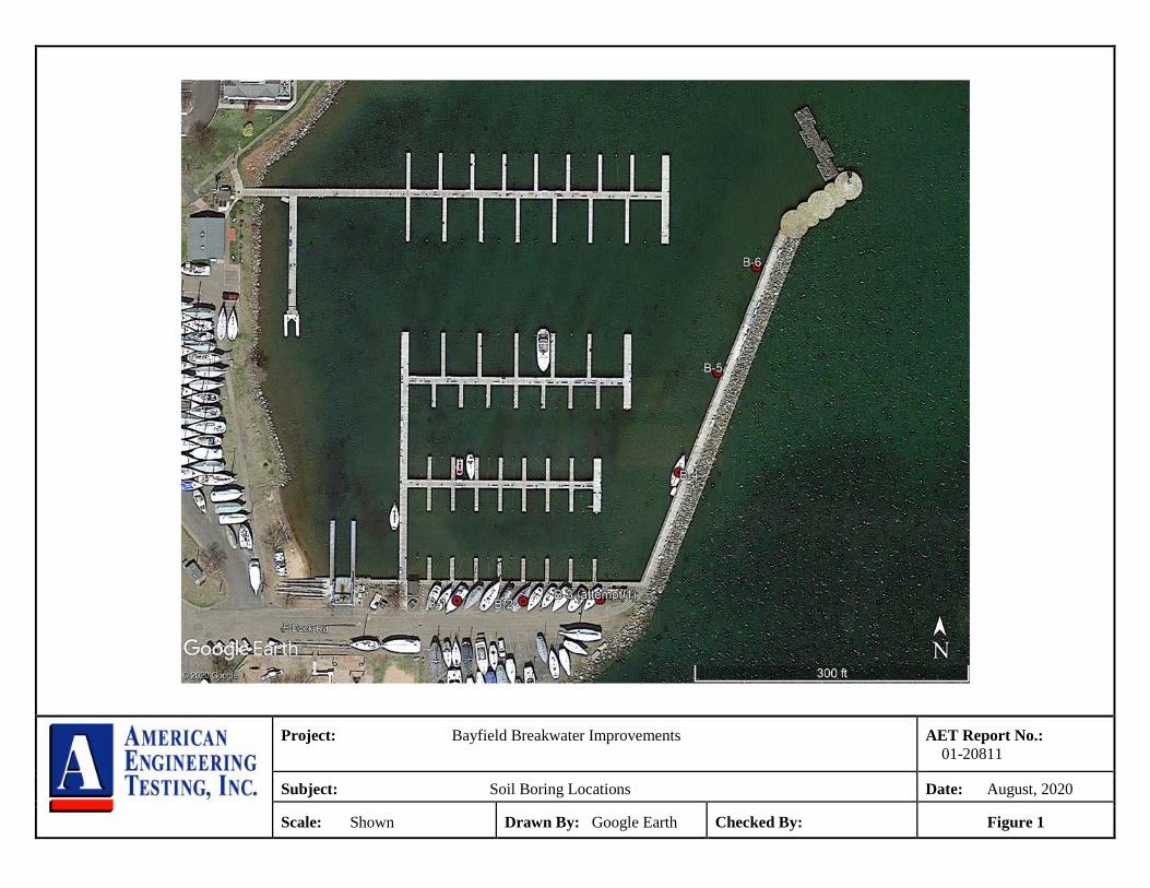
The subsurface exploration program conducted by SES for the project consisted of six standard penetration test borings. Boring locations were selected by representatives of MSA. We provided input on adequate boring depths. The logs of the borings and details of the methods used appear in Appendix A. The logs contain information concerning soil layering, soil classification, geologic origins, and moisture condition. A density description or consistency is also noted for the natural soils, which is based on the standard penetration resistance (N-value). The boring locations are shown on Figure 1 in Appendix A. The borings were located in the field by AET personnel using a GPS device. Approximate surface elevations were also attained using this device.
4.2 Laboratory Testing
The laboratory test program included four gradations of granular materials sampled below the mud line at two of the borings. The test results appear in Appendix A on the individual boring logs adjacent to the samples upon which they were performed, or on the data sheets following the logs.
5.0 SITE CONDITIONS
5.1 Surface Observations
Photographs taken at the time the field exploration was occurring are included in Appendix A. Appendix A also includes a diagram of the south parking area with some general observations of its surface composition and condition. The wooden docks north of the parking area and along the protected side of the breakwater are significantly weathered and unlevel. Occasional submerged wooden piers/piles, boulders, and wood debris were noted adjacent to the wood docks. A portion of the parking/boat storage area is covered with a thin bitumen chip seal product. Some sinkholes were observed in the lot adjacent to the dock in this area.

Report of Geotechnical Exploration Breakwater Improvements; Bayfield, WI AMERICAN August 28, 2020 ENGINEERING Report No. 01-20811 TESTING, INC.
Page 3 of 9
5.2 Subsurface Soils/Geology
Borings B-1, B-2, and B-3 were conducted in the parking/boat storage area on the south side of the marina. Fill soils consisting of silty sand and sand with gravel and wood were noted from the surface to about the 15-foot depth. We suspect the fill soils were not placed in a controlled manner judging from the variability of recorded N-values. Boring B-3 consistently encountered boulder obstructions at a depth of about 4 feet after moving it west four times in 5-foot increments from its originally intended location. The coarse alluvial sand deposits encountered below the fill materials consist of fine to medium grained sands with a little gravel. Borings B-4, B-5, and B-6 were performed from a barge along the leeward side of the breakwater; water depths were in the range of 8 to 10 feet at these locations. At the mudline a 1½- to 2-foot-thick layer of soft lake bottom deposits was encountered above several feet of apparent fill consisting of silty sand and gravelly sand. The borings were then advanced into relatively clean sands (SP) with a little gravel that extended to their respective termination depths. 5.3 Groundwater
The groundwater in the area is dictated by the level of Lake Superior. An undated survey of the site provided showed a lake level near 602.6 MSLD. Water levels at the borings were generally in the range of 603± to 604±.
6.0 RECOMMENDATIONS
6.1 Approach Discussion
Figure 6.1 illustrates the intended improvements that will be made to the existing breakwater:

Report of Geotechnical Exploration Breakwater Improvements; Bayfield, WI AMERICAN August 28, 2020 ENGINEERING Report No. 01-20811 TESTING, INC.
Page 4 of 9
Figure 6.1 – Planned breakwater improvement cross section
The existing wooden crib is about 24 feet wide. The top of the crib elevation is at elevation 606. On the lake side of the breakwater, large diameter armor stone will be placed to a height of about 3 feet above the present elevation of the boulder-filled timber crib structure and pushed out into the lake at a 2H:1V slope. The armor stone is intended to enhance the breakwater’s resistance to wave and ice forces. Along the harbor side of the existing breakwater and south dock sheet piles will be installed to create a hard edge at the harbor/land interface. The sheet piling is intended to support the materials on the land side of the sheets and prevent further erosion into the harbor. 6.2 Global (Overall) Stability
6.2.1 Procedure
We performed global stability analysis of the breakwater improvements by using the computer program SLOPE/W of GeoStudio 2020 (GEO-SLOPE International, Ltd.) The software uses limit-equilibrium methods for both circular and non-circular failure surfaces. For this project, the Morgernstern-Price method was used to analyze critical slip surface of the breakwater. Based on the provided contour map, sheet number G-102, we performed two global stability analyses on two breakwater stations: 1+00 and 3+00. The breakwater stations were selected based on the critical and typical cross section of the new structures. At station 1+00, the lakeside elevation drops from 590 to 550 feet over a 150-foot distance, while station 3+00 represents the remaining breakwater stations where the lake floor is more or less flat.

Report of Geotechnical Exploration Breakwater Improvements; Bayfield, WI AMERICAN August 28, 2020 ENGINEERING Report No. 01-20811 TESTING, INC.
Page 5 of 9
Based on the borings drilled along the breakwater, we use a drained friction angle of 29° for the sand beneath the breakwater. We assume the armor stone to have a total unit weight of 140 pcf, and a drained friction angle of 32°, considering its long-term performance due to fines intrusion and clogging. The existing wooden crib was modeled as “high strength” material, thereby forcing the slip surface behind (harbor side) the crib. Although a new sheet pile is planned at the harbor side, the SLOPE/W model that we performed disregarded the shearing resistance provided by the sheet pile. Based on available Lake Superior water level data provided on the USACE website (https://www.lre.usace.army.mil/Missions/Great-Lakes-Information/), the long-term annual average water elevation is at 601.7 feet and low water elevation was around 599.7 feet. We also assumed that the difference between the lakeside and harbor side water level is negligible (i.e. seepage gradient is small). Therefore, we used a hydrostatic water table to represent the water condition in our model. 6.2.2 Results
A factor of safety of 1.5 or greater is considered acceptable for the breakwater global stability. The computed factor of safety for stations 1+00 and 3+00 are both greater than 1.5, even at low water condition which is expected to control the stability. Assuming the existing wooden crib has adequate strength to support its own weight, it is our opinion the proposed 2H:1V graded slope with armor stone will be stable. Details of the wall geometry, parameters used to evaluate the subsurface conditions, and results of the global stability results are shown in the attached computer program printouts.

Report of Geotechnical Exploration Breakwater Improvements; Bayfield, WI AMERICAN August 28, 2020 ENGINEERING Report No. 01-20811 TESTING, INC.
Page 6 of 9
6.3 Sheet Pile Analysis and Recommendations
The model that we analyzed for sheet pile support/retention is shown in Figure 6.2.
Figure 6.2 – Section through Sheet Pile
Tying the wall back was deemed impractical because of the boulders that were used to fill the existing timber crib wall. Therefore, we analyzed a typical sheet pile section for this application that would provide cantilever support of the harbor side of the existing crib wall and southerly limits paralleling the dock and parking area. NAVFAC DM 7-2 charts were utilized to evaluate the sheet pile’s penetration depth and maximum moment. Results indicate the sheet pile should have a section modulus of not less than 33.4 in³/ft. A maximum design moment of 78,000 ft-lb/ft was assumed. An SKZ 22 or SKZ 24 sheet pile section (Nucor Skyline designation) would provide the recommended modulus. It is also recommended the sheet piling meet ASTM A 572 Grade 60. Required minimum sheet pile length is estimated at 35 feet, providing at least 21 feet of embedment below the mudline. Adding surcharge loads (anything above pedestrian loading)

Report of Geotechnical Exploration Breakwater Improvements; Bayfield, WI AMERICAN August 28, 2020 ENGINEERING Report No. 01-20811 TESTING, INC.
Page 7 of 9
behind the sheet piling and dredging in front of the sheet piling must be restricted. Examples of surcharge loading that should be prohibited include the stockpiling of anything that would add weight and driving force behind the sheeting. For example, dredged soils, riprap, construction equipment, and trailered boat storage should be kept more than 10 feet away from the sheet pile wall. The granular, non-cohesive nature of the native soils should be conducive to vibratory installation of the sheets. Boulders, rubble, and abandoned piling/piers situated along the sheet pile wall alignment, if present, will obstruct or skew the vertical alignment of the sheets during installation. Such potential obstructions should be identified and removed prior to construction. The materials being retained and the soils below the mud line in the harbor are not considered significantly corrosive. The water in this particular environment is also not considered significantly corrosive unless polluted. Corrosion is most noticeable at the water line on sheet piling used in marine applications. We have assumed the water line will not fluctuate more than a few feet during the life of the structure and that the water line will always be several feet above the mud line. The risk of loss of sheet pile steel section from corrosion where the maximum bending moment is occurring is judged to be negligible. Therefore, it is our opinion the structural integrity of the sheets should not be compromised from corrosion. Corrosion protection is not deemed necessary.
6.4 Possible Design Modifications
At the time of this report, changing the crest elevation of the armor stone from 609 to 608 feet was being considered. Regarding the stability analysis we performed, dropping the crest elevation by 1 foot does not impact this analysis significantly. The factor of safety will still meet the stability criterion of 1.5. The lowered armor stone crest elevation does not impact recommended sheet pile section/length. Another design modification that is being contemplated is the elimination of the armor stone embankment. The breakwater would substitute a continuous sheet pile wall instead of the armor stone embankment on the lake side of its alignment, shown on Figure 6.3.

Report of Geotechnical Exploration Breakwater Improvements; Bayfield, WI AMERICAN August 28, 2020 ENGINEERING Report No. 01-20811 TESTING, INC.
Page 8 of 9
Figure 6.3 – Alternative Design Modification: New Sheet Pile on Lakeward Side
This concept could possibly employ tie-backs between the tops of the inner harbor and lake side sheet pile walls. It is our opinion this idea may have merit as it seems to be much less laborious. Stability would probably not be compromised, but we should be requested to perform a stability analysis if this alternative will be pursued. Given the current wooden crib condition, the addition of the lakeward sheet pile wall could actually be viewed as a means of enhancing breakwater stability along the lakeside of the embankment; less load (due to eliminating the sloped armor stone) should equate to less driving force causing instability. However, the lakeward loading condition can be quite different from the inner harbor side; therefore, we recommend that the new sheet pile, including embedment length and section, be evaluated based on the lakeward loading condition. Tie-backs between the tops of the sheets will reinforce the lateral movement at the tops. Tie-backs with walers would seemingly stiffen the entire breakwater system, and possibly reduce sheet pile section and length, relying less on the need for cantilever sufficient embedment.

Report of Geotechnical Exploration Breakwater Improvements; Bayfield, WI AMERICAN August 28, 2020 ENGINEERING Report No. 01-20811 TESTING, INC.
Page 9 of 9
7.0 CONSTRUCTION CONSIDERATIONS
7.1 Observation and Testing
The recommendations in this report are based on the subsurface conditions found at our test boring locations. Since the soil conditions can be expected to vary away from the soil boring locations, we recommend on-site observation by a geotechnical engineer/technician during construction to evaluate these potential changes. 8.0 ASTM STANDARDS
When we refer to an ASTM Standard in this report, we mean that our services were performed in general accordance with that standard. Compliance with any other standards referenced within the specified standard is neither inferred nor implied. 9.0 LIMITATIONS
Within the limitations of scope, budget, and schedule, we have endeavored to provide our services according to generally accepted geotechnical engineering practices at this time and location. Other than this, no warranty, express or implied, is intended. Important information regarding risk management and proper use of this report is given in Appendix B entitled “Geotechnical Report Limitations and Guidelines for Use.”

Appendix A
Geotechnical Field Exploration and Testing Boring Log Notes
Unified Soil Classification System Figure 1 – Boring Locations
Figure 2 – General Parking Lot Observations Subsurface Boring Logs
Gradation Curves Slope Stability Sections
Photographs

Appendix A Geotechnical Field Exploration and Testing
Report No. 01-20811
Appendix A - Page 1 of 2 AMERICAN ENGINEERING TESTING, INC.
A.1 FIELD EXPLORATION The subsurface conditions at the site were explored by drilling and sampling six ( 6 ) standard penetration test borings by others. The locations of the borings appear on Figure 1, preceding the Subsurface Boring Logs in this appendix. A.2 SAMPLING METHODS A.2.1 Split-Spoon Samples (SS) - Calibrated to N60 Values Standard penetration (split-spoon) samples were collected in general accordance with ASTM: D1586 with one primary modification. The ASTM test method consists of driving a 2-inch O.D. split-barrel sampler into the in-situ soil with a 140-pound hammer dropped from a height of 30 inches. The sampler is driven a total of 18 inches into the soil. After an initial set of 6 inches, the number of hammer blows to drive the sampler the final 12 inches is known as the standard penetration resistance or N-value. Our method uses a modified hammer weight, which is determined by measuring the system energy using a Pile Driving Analyzer (PDA) and an instrumented rod. In the past, standard penetration N-value tests were performed using a rope and cathead for the lift and drop system. The energy transferred to the split-spoon sampler was typically limited to about 60% of its potential energy due to the friction inherent in this system. This converted energy then provides what is known as an N60 blow count.
A.2.2 Disturbed Samples (DS)/Spin-up Samples (SU) Sample types described as “DS” or “SU” on the boring logs are disturbed samples, which are taken from the flights of the auger. Because the auger disturbs the samples, possible soil layering and contact depths should be considered approximate. A.2.3 Sampling Limitations Unless actually observed in a sample, contacts between soil layers are estimated based on the spacing of samples and the action of drilling tools. Cobbles, boulders, and other large objects generally cannot be recovered from test borings, and they may be present in the ground even if they are not noted on the boring logs. Determining the thickness of “topsoil” layers is usually limited, due to variations in topsoil definition, sample recovery, and other factors. Visual-manual description often relies on color for determination, and transitioning changes can account for significant variation in thickness judgment. Accordingly, the topsoil thickness presented on the logs should not be the sole basis for calculating topsoil stripping depths and volumes. If more accurate information is needed relating to thickness and topsoil quality definition, alternate methods of sample retrieval and testing should be employed. A.3 CLASSIFICATION METHODS Soil descriptions shown on the boring logs are based on the Unified Soil Classification (USC) system. The USC system is described in ASTM: D2487 and D2488. Where laboratory classification tests (sieve analysis or Atterberg Limits) have been performed, accurate classifications per ASTM: D2487 are possible. Otherwise, soil descriptions shown on the boring logs are visual-manual judgments. Charts are attached which provide information on the USC system, the descriptive terminology, and the symbols used on the boring logs. The boring logs include descriptions of apparent geology. The geologic depositional origin of each soil layer is interpreted primarily by observation of the soil samples, which can be limited. Observations of the surrounding topography, vegetation, and development can sometimes aid this judgment. A.4 WATER LEVEL MEASUREMENTS The ground water level measurements are shown at the bottom of the boring logs. The following information appears under “Water Level Measurements” on the logs:
Date and Time of measurement Sampled Depth: lowest depth of soil sampling at the time of measurement Casing Depth: depth to bottom of casing or hollow-stem auger at time of measurement Cave-in Depth: depth at which measuring tape stops in the borehole Water Level: depth in the borehole where free water is encountered Drilling Fluid Level: same as Water Level, except that the liquid in the borehole is drilling fluid

Appendix A Geotechnical Field Exploration and Testing
Report No. 01-20811
Appendix A - Page 2 of 2 AMERICAN ENGINEERING TESTING, INC.
The true location of the water table at the boring locations may be different than the water levels measured in the boreholes. This is possible because there are several factors that can affect the water level measurements in the borehole. Some of these factors include permeability of each soil layer in profile, presence of perched water, amount of time between water level readings, presence of drilling fluid, weather conditions, and use of borehole casing. A.5 LABORATORY TEST METHODS A.5.1 Water Content Tests Conducted per AET Procedure 01-LAB-010, which is performed in general accordance with ASTM: D2216 and AASHTO: T265. A.5.2 Atterberg Limits Tests Conducted per AET Procedure 01-LAB-030, which is performed in general accordance with ASTM: D4318 and AASHTO: T89, T90. A.5.3 Sieve Analysis of Soils (thru #200 Sieve) Conducted per AET Procedure 01-LAB-040, which is performed in general conformance with ASTM: D6913, Method A. A.5.4 Particle Size Analysis of Soils (with hydrometer) Conducted per AET Procedure 01-LAB-050, which is performed in general accordance with ASTM: D422 and AASHTO: T88. A.5.5 Unconfined Compressive Strength of Cohesive Soil Conducted per AET Procedure 01-LAB-080, which is performed in general accordance with ASTM: D2166 and AASHTO: T208. A.5.6 Laboratory Soil Resistivity using the Wenner Four-Electrode Method Conducted per AET Procedure 01-LAB-090, which is performed using Soil Box apparatus in the laboratory in general accordance with ASTM: G57 A.6 TEST STANDARD LIMITATIONS Field and laboratory testing are done in general conformance with the described procedures. Compliance with any other standards referenced within the specified standard is neither inferred nor implied. A.7 SAMPLE STORAGE Unless notified to do otherwise, we routinely retain representative samples of the soils recovered from the borings for a period of 30 days.

01REP052C (7/11) AMERICAN ENGINEERING TESTING, INC.
BORING LOG NOTES
DRILLING AND SAMPLING SYMBOLS TEST SYMBOLS
Symbol Definition Symbol Definition
AR: Sample of material obtained from cuttings blown out
the top of the borehole during air rotary procedure.
B, H, N: Size of flush-joint casing
CAS: Pipe casing, number indicates nominal diameter in
inches
COT: Clean-out tube
DC: Drive casing; number indicates diameter in inches
DM: Drilling mud or bentonite slurry
DR: Driller (initials)
DS: Disturbed sample from auger flights
DP: Direct push drilling; a 2.125 inch OD outer casing
with an inner 1½ inch ID plastic tube is driven
continuously into the ground.
FA: Flight auger; number indicates outside diameter in
inches
HA: Hand auger; number indicates outside diameter
HSA: Hollow stem auger; number indicates inside diameter
in inches
LG: Field logger (initials)
MC: Column used to describe moisture condition of
samples and for the ground water level symbols
N (BPF): Standard penetration resistance (N-value) in blows per
foot (see notes)
NQ: NQ wireline core barrel
PQ: PQ wireline core barrel
RDA: Rotary drilling with compressed air and roller or drag
bit.
RDF: Rotary drilling with drilling fluid and roller or drag bit
REC: In split-spoon (see notes), direct push and thin-walled
tube sampling, the recovered length (in inches) of
sample. In rock coring, the length of core recovered
(expressed as percent of the total core run). Zero
indicates no sample recovered.
SS: Standard split-spoon sampler (steel; 1.5" is inside
diameter; 2" outside diameter); unless indicated
otherwise
SU Spin-up sample from hollow stem auger
TW: Thin-walled tube; number indicates inside diameter in
inches
WASH: Sample of material obtained by screening returning
rotary drilling fluid or by which has collected inside
the borehole after “falling” through drilling fluid
WH: Sampler advanced by static weight of drill rod and
hammer
WR: Sampler advanced by static weight of drill rod
94mm: 94 millimeter wireline core barrel
▼: Water level directly measured in boring
: Estimated water level based solely on sample appearance
CONS: One-dimensional consolidation test
DEN: Dry density, pcf
DST: Direct shear test
E: Pressuremeter Modulus, tsf
HYD: Hydrometer analysis
LL: Liquid Limit, %
LP: Pressuremeter Limit Pressure, tsf
OC: Organic Content, %
PERM: Coefficient of permeability (K) test; F - Field;
L - Laboratory
PL: Plastic Limit, %
qp: Pocket Penetrometer strength, tsf (approximate)
qc: Static cone bearing pressure, tsf
qu: Unconfined compressive strength, psf
R: Electrical Resistivity, ohm-cms
RQD: Rock Quality Designation of Rock Core, in percent
(aggregate length of core pieces 4" or more in length
as a percent of total core run)
SA: Sieve analysis
TRX: Triaxial compression test
VSR: Vane shear strength, remolded (field), psf
VSU: Vane shear strength, undisturbed (field), psf
WC: Water content, as percent of dry weight
%-200: Percent of material finer than #200 sieve
STANDARD PENETRATION TEST NOTES
(Calibrated Hammer Weight)
The standard penetration test consists of driving a split-spoon
sampler with a drop hammer (calibrated weight varies to provide
N60 values) and counting the number of blows applied in each of
three 6" increments of penetration. If the sampler is driven less
than 18" (usually in highly resistant material), permitted in
ASTM: D1586, the blows for each complete 6" increment and for
each partial increment is on the boring log. For partial increments,
the number of blows is shown to the nearest 0.1' below the slash.
The length of sample recovered, as shown on the “REC” column,
may be greater than the distance indicated in the N column. The
disparity is because the N-value is recorded below the initial 6"
set (unless partial penetration defined in ASTM: D1586 is
encountered) whereas the length of sample recovered is for the
entire sampler drive (which may even extend more than 18").

01CLS021 (07/08) AMERICAN ENGINEERING TESTING, INC.
UNIFIED SOIL CLASSIFICATION SYSTEM
ASTM Designations: D 2487, D2488
AMERICAN
ENGINEERING
TESTING, INC.
Criteria for Assigning Group Symbols and Group Names Using Laboratory TestsA
Soil Classification Notes ABased on the material passing the 3-in
(75-mm) sieve. BIf field sample contained cobbles or
boulders, or both, add “with cobbles or
boulders, or both” to group name. CGravels with 5 to 12% fines require dual
symbols:
GW-GM well-graded gravel with silt
GW-GC well-graded gravel with clay
GP-GM poorly graded gravel with silt
GP-GC poorly graded gravel with clay DSands with 5 to 12% fines require dual
symbols:
SW-SM well-graded sand with silt
SW-SC well-graded sand with clay
SP-SM poorly graded sand with silt
SP-SC poorly graded sand with clay
(D30)
2
ECu = D60 /D10, Cc =
D10 x D60
FIf soil contains >15% sand, add “with
sand” to group name. GIf fines classify as CL-ML, use dual
symbol GC-GM, or SC-SM. HIf fines are organic, add “with organic
fines” to group name. IIf soil contains >15% gravel, add “with
gravel” to group name. JIf Atterberg limits plot is hatched area,
soil is a CL-ML silty clay. KIf soil contains 15 to 29% plus No. 200
add “with sand” or “with gravel”,
whichever is predominant. LIf soil contains >30% plus No. 200,
predominantly sand, add “sandy” to
group name.
MIf soil contains >30% plus No. 200,
predominantly gravel, add “gravelly”
to group name. NPl>4 and plots on or above “A” line.
OPl<4 or plots below “A” line.
PPl plots on or above “A” line.
QPl plots below “A” line.
RFiber Content description shown below.
Group
Symbol
Group NameB
Coarse-Grained
Soils More
than 50%
retained on
No. 200 sieve
Gravels More
than 50% coarse
fraction retained
on No. 4 sieve
Clean Gravels
Less than 5%
finesC
Cu>4 and 1<Cc<3E
GW Well graded gravelF
Cu<4 and/or 1>Cc>3E
GP Poorly graded gravelF
Gravels with
Fines more
than 12% fines C
Fines classify as ML or MH GM Silty gravelF.G.H
Fines classify as CL or CH GC Clayey gravelF.G.H
Sands 50% or more of coarse
fraction passes
No. 4 sieve
Clean Sands Less than 5%
finesD
Cu>6 and 1<Cc<3E
SW Well-graded sandI
Cu<6 and/or 1>Cc>3E
SP Poorly-graded sandI
Sands with
Fines more
than 12% fines D
Fines classify as ML or MH SM Silty sandG.H.I
Fines classify as CL or CH SC Clayey sandG.H.I
Fine-Grained
Soils 50% or
more passes
the No. 200
sieve
(see Plasticity
Chart below)
Silts and Clays
Liquid limit less
than 50
inorganic PI>7 and plots on or above
“A” lineJ
CL Lean clayK.L.M
PI<4 or plots below
“A” lineJ
ML SiltK.L.M
organic Liquid limit–oven dried <0.75
Liquid limit – not dried
OL Organic clayK.L.M.N
Organic siltK.L.M.O
Silts and Clays
Liquid limit 50
or more
inorganic PI plots on or above “A” line CH Fat clayK.L.M
PI plots below “A” line MH Elastic siltK.L.M
organic Liquid limit–oven dried <0.75
Liquid limit – not dried
OH Organic clayK.L.M.P
Organic siltK.L.M.Q
Highly organic soil
Primarily organic matter, dark in color, and organic in odor
PT PeatR
3 2 ½ 1 ¾ 4 10 20 40 60 140 200100
80
60
40
20
0
0
20
40
60
80
100
81
Sieve NumberScreen Opening (in.)
50 10 5 1.0 0.10.5
PARTICLE SIZE IN MILLIMETERS
SIEVE ANALYSIS
PE
RC
EN
T P
AS
SIN
G
PE
RC
EN
T R
ET
AIN
ED
D60 = 15mm
D30 = 2.5mm
D10 = 0.075mm
Cu = = = 200D60
D10
15
0.075Cc = = = 5.6
(D30)
D10 x D60
2.5
0.075 x 15
2 2
CL-ML
For classification of fine-grained soils and fine-grained fraction of coarse-grained soils.
Equation of "A"-lineHorizontal at PI = 4 to LL = 25.5. then PI = 0.73 (LL-20)
Equation of "U"-lineVertical at LL = 16 to PI = 7. then PI = 0.9 (LL-8)
"A" L
INE
"U" L
INE
CL OR O
L
CH OR OH
10 20 30 40 50 60 70 80 90 100 110 0 0
10
20
30
40
50
60
16
7
4
PLA
ST
ICIT
Y IN
DE
X (
PI)
LIQUID LIMIT (LL)
Plasticity Chart
ADDITIONAL TERMINOLOGY NOTES USED BY AET FOR SOIL IDENTIFICATION AND DESCRIPTION
Grain Size Term Particle Size
Boulders Over 12" Cobbles 3" to 12"
Gravel #4 sieve to 3"
Sand #200 to #4 sieve
Fines (silt & clay) Pass #200 sieve
Gravel Percentages
Term Percent
A Little Gravel 3% - 14%
With Gravel 15% - 29% Gravelly 30% - 50%
Consistency of Plastic Soils Term N-Value, BPF
Very Soft less than 2 Soft 2 - 4
Firm 5 - 8
Stiff 9 - 15
Very Stiff 16 - 30
Hard Greater than 30
Relative Density of Non-Plastic Soils Term N-Value, BPF
Very Loose 0 - 4 Loose 5 - 10
Medium Dense 11 - 30
Dense 31 - 50
Very Dense Greater than 50
Moisture/Frost Condition
(MC Column)
D (Dry): Absence of moisture, dusty, dry to
touch. M (Moist): Damp, although free water not
visible. Soil may still have a high
water content (over “optimum”).
W (Wet/ Free water visible, intended to
Waterbearing): describe non-plastic soils.
Waterbearing usually relates to
sands and sand with silt. F (Frozen): Soil frozen
Layering Notes
Laminations: Layers less than
½" thick of
differing material or color.
Lenses: Pockets or layers
greater than ½"
thick of differing
material or color.
Peat Description
Fiber Content
Term (Visual Estimate)
Fibric Peat: Greater than 67%
Hemic Peat: 33 – 67%
Sapric Peat: Less than 33%
Organic Description (if no lab tests)
Soils are described as organic, if soil is not peat
and is judged to have sufficient organic fines
content to influence the Liquid Limit properties. Slightly organic used for borderline cases.
Root Inclusions
With roots: Judged to have sufficient quantity
of roots to influence the soil
properties.
Trace roots: Small roots present, but not judged
to be in sufficient quantity to significantly affect soil properties.
ML OR OL
MH OR OH
Project: Bayfield Breakwater Improvements
AET Report No.: 01-20811
Subject: Soil Boring Locations Date: August, 2020
Scale: Shown Drawn By: Google Earth Checked By: Figure 1

Project: Bayfield Breakwater Improvements
AET Report No.: 01-20811
Subject: General Parking Lot Observations Date: August 2020
Scale: Shown Drawn By: Google Earth Checked By: Figure 2

SS
SS
SS
SS
SS
SS
SS
SS
SS
SS
SS
12
12
6
4
14
16
16
12
10
12
11
7
6
13
6
5
8
12
23
7
20
12
.25" Bituminous pavementFILL, mostly gravelly silty sand, brownFILL, mostly sand, light brown
FILL, mostly silty sand and gravelly poorlygraded sand, with wood, brown
POORLY GRADED SAND WITH SILT, a littlegravel, fine to medium grained, brown,waterbearing, medium dense to loose (SP-SM)
END OF BORING
M
M
M/W
W
W
W
W
W
W
W
W
FILL
COARSEALLUVIUM
5.0
7.7
5/28/20
5/28/20
SAMPLEDDEPTH3.25" HSA
RD w/DM
DRILLINGFLUID LEVEL
WATER LEVEL MEASUREMENTS
2.4
Obscured
7/16/20
605.0
Rig:
8:45
10:15
BLDR:
2.8
None
WATERLEVEL
Surface Elevation
DATE0-10'
10'-35'
NOTE: REFER TO
THE ATTACHED
SHEETS FOR AN
EXPLANATION OF
TERMINOLOGY ON
THIS LOG
CASINGDEPTH
B-61
None
13.0BORINGCOMPLETED:
JW LG:
TIME
12.0
36.5
DEPTH: DRILLING METHOD
CAVE-INDEPTH
01-20811
LLDEN
AMERICANENGINEERINGTESTING, INC.
GEOLOGY
1
2
3
4
5
6
7
8
9
10
11
12
13
14
15
16
17
18
19
20
21
22
23
24
25
26
27
28
29
30
31
32
33
34
35
36
PL
B-1 (p. 1 of 1)AET No:
Project:
MCDEPTH
INFEET
03/2011
Breakwater Improvement Project; Bayfield, WI
MATERIAL DESCRIPTIONRECIN.
SAMPLETYPE WC
01-DHR-060
NFIELD & LABORATORY TESTS
Log of Boring No.
SURFACE BORING LOG
%-#200
AE
T_
CO
RP
01-
2081
1.G
PJ
AE
T+
CP
T+
WE
LL_2
0181
012
_JG
.GD
T
8/28
/20

SS
SS
SS
SS
SS
SS
SS
SS
SS
SS
SS
10
12
10
3
10
8
10
10
9
10
8
8
7
13
WH
6
6
21
7
6
6
8
.25" Bituminous pavementFILL, mostly gravelly silty sand, brownFILL, mostly sand, a little gravel, brown
FILL, mostly sand, a little gravel with wood,brown
SAND, a little gravel, fine to medium grained,brown, moist to waterbearing, medium dense toloose (SP)
END OF BORING
M
M/W
M/W
M/W
W
W
W
W
W
W
W
FILL
COARSEALLUVIUM
5/27/20
5/27/20
SAMPLEDDEPTH3.25" HSA
RD w/DM
DRILLINGFLUID LEVEL
WATER LEVEL MEASUREMENTS
2.3
Obscured
605.6
Rig:
12:45
4:00
BLDR:
2.6
None
WATERLEVEL
Surface Elevation
DATE0-10'
10'-35'
NOTE: REFER TO
THE ATTACHED
SHEETS FOR AN
EXPLANATION OF
TERMINOLOGY ON
THIS LOG
CASINGDEPTH
B-61
None
15.0BORINGCOMPLETED:
JW LG:
TIME
11.5
36.5
DEPTH: DRILLING METHOD
CAVE-INDEPTH
01-20811
LLDEN
AMERICANENGINEERINGTESTING, INC.
GEOLOGY
1
2
3
4
5
6
7
8
9
10
11
12
13
14
15
16
17
18
19
20
21
22
23
24
25
26
27
28
29
30
31
32
33
34
35
36
PL
B-2 (p. 1 of 1)AET No:
Project:
MCDEPTH
INFEET
03/2011
Breakwater Improvement Project; Bayfield, WI
MATERIAL DESCRIPTIONRECIN.
SAMPLETYPE WC
01-DHR-060
NFIELD & LABORATORY TESTS
Log of Boring No.
SURFACE BORING LOG
%-#200
AE
T_
CO
RP
01-
2081
1.G
PJ
AE
T+
CP
T+
WE
LL_2
0181
012
_JG
.GD
T
8/28
/20

SS
SS
SS
7
11
2
9
33
FILL, mostly sand with gravel, brown
END OF BORING - AUGER REFUSAL 50/0.3
M
M
M
FILL
5/27/20
SAMPLEDDEPTH3.25" HSA
DRILLINGFLUID LEVEL
WATER LEVEL MEASUREMENTS
None
604.9
Rig:
10:45
BLDR:
2.5
WATERLEVEL
Surface Elevation
DATE0-4.6'
NOTE: REFER TO
THE ATTACHED
SHEETS FOR AN
EXPLANATION OF
TERMINOLOGY ON
THIS LOG
CASINGDEPTH
B-61
None
BORINGCOMPLETED:
JW LG:
TIME
4.3
DEPTH: DRILLING METHOD
CAVE-INDEPTH
01-20811
LLDEN
AMERICANENGINEERINGTESTING, INC.
GEOLOGY
1
2
3
4
PL
B-3 (p. 1 of 1)AET No:
Project:
MCDEPTH
INFEET
03/2011
Breakwater Improvement Project; Bayfield, WI
MATERIAL DESCRIPTIONRECIN.
SAMPLETYPE WC
01-DHR-060
NFIELD & LABORATORY TESTS
Log of Boring No.
SURFACE BORING LOG
%-#200
AE
T_
CO
RP
01-
2081
1.G
PJ
AE
T+
CP
T+
WE
LL_2
0181
012
_JG
.GD
T
8/28
/20

SS
SS
SS
SS
SS
SS
SS
12
10
2
14
17
14
12
5
17
26
22
25
10
7
AIR
WATER at 1.5'
MUD (not sampled)
FILL, mostly gravelly sand, brown
SAND, a little gravel, fine to medium grained,brown, waterbearing, loose to medium dense(SP)
W
W
W
W
W
W
W
FILL
COARSEALLUVIUM
5/27/20
SAMPLEDDEPTH3.25" HSA
RD w/DM
DRILLINGFLUID LEVEL
WATER LEVEL MEASUREMENTS
Obscured
605.5
Rig:
3:45
MP/SNDR:
None
WATERLEVEL
Surface Elevation
DATE0-12'
12'-55'
NOTE: REFER TO
THE ATTACHED
SHEETS FOR AN
EXPLANATION OF
TERMINOLOGY ON
THIS LOG
CASINGDEPTH
D-25
19.0
BORINGCOMPLETED:
JD LG:
TIME
57.0
DEPTH: DRILLING METHOD
CAVE-INDEPTH
01-20811
LLDEN
AMERICANENGINEERINGTESTING, INC.
GEOLOGY
1
2
3
4
5
6
7
8
9
10
11
12
13
14
15
16
17
18
19
20
21
22
23
24
25
26
27
28
29
30
31
32
33
34
35
36
37
38
39
PL
B-4 (p. 1 of 2)AET No:
Project:
MCDEPTH
INFEET
03/2011
Breakwater Improvement Project; Bayfield, WI
MATERIAL DESCRIPTIONRECIN.
SAMPLETYPE WC
01-DHR-060
NFIELD & LABORATORY TESTS
Log of Boring No.
SURFACE BORING LOG
%-#200
AE
T_
CO
RP
01-
2081
1.G
PJ
AE
T+
CP
T+
WE
LL_2
0181
012
_JG
.GD
T
8/28
/20
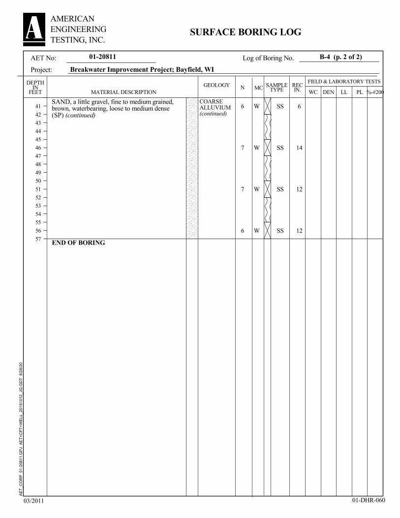
SS
SS
SS
SS
6
14
12
12
6
7
7
6
SAND, a little gravel, fine to medium grained,brown, waterbearing, loose to medium dense(SP) (continued)
END OF BORING
W
W
W
W
COARSEALLUVIUM(continued)
01-20811
LLDEN
AMERICANENGINEERINGTESTING, INC.
GEOLOGY
41
42
43
44
45
46
47
48
49
50
51
52
53
54
55
56
57
PL
B-4 (p. 2 of 2)AET No:
Project:
MCDEPTH
INFEET
03/2011
Breakwater Improvement Project; Bayfield, WI
MATERIAL DESCRIPTIONRECIN.
SAMPLETYPE WC
01-DHR-060
NFIELD & LABORATORY TESTS
Log of Boring No.
SURFACE BORING LOG
%-#200
AE
T_
CO
RP
01-
2081
1.G
PJ
AE
T+
CP
T+
WE
LL_2
0181
012
_JG
.GD
T
8/28
/20

SS
SS
SS
SS
SS
SS
SS
SS
10
12
13
12
11
14
14
4
3
14
34
22
13
14
8
6
AIR
WATER at 1.5'
MUD (not sampled)
FILL, mostly silty sand, trace roots, brown
FILL, mostly gravelly sand, brown
GRAVELLY POORLY GRADED SAND, fineto medium grained, waterbearing, medium dense(SP)SAND, with gravel, fine to medium grained,waterbearing, medium dense to very dense (SP)
POORLY GRADED SAND, fine to mediumgrained, waterbearing, loose (SP)
W
W
W
W
W
W
W
W
FILL
COARSEALLUVIUM 4.5
2.1
5/26/20
SAMPLEDDEPTH3.25" HSA
RD w/DM
DRILLINGFLUID LEVEL
WATER LEVEL MEASUREMENTS
Obscured
7/16/20
604.9
Rig:
4:30
MP/SNDR:
None
WATERLEVEL
Surface Elevation
DATE0-11½'
11½'-43½'
NOTE: REFER TO
THE ATTACHED
SHEETS FOR AN
EXPLANATION OF
TERMINOLOGY ON
THIS LOG
CASINGDEPTH
D-25
20.0
BORINGCOMPLETED:
JD LG:
TIME
27.0
DEPTH: DRILLING METHOD
CAVE-INDEPTH
01-20811
LLDEN
AMERICANENGINEERINGTESTING, INC.
GEOLOGY
1
2
3
4
5
6
7
8
9
10
11
12
13
14
15
16
17
18
19
20
21
22
23
24
25
26
27
28
29
30
31
32
33
34
35
36
37
38
39
PL
B-5 (p. 1 of 2)AET No:
Project:
MCDEPTH
INFEET
03/2011
Breakwater Improvement Project; Bayfield, WI
MATERIAL DESCRIPTIONRECIN.
SAMPLETYPE WC
01-DHR-060
NFIELD & LABORATORY TESTS
Log of Boring No.
SURFACE BORING LOG
%-#200
AE
T_
CO
RP
01-
2081
1.G
PJ
AE
T+
CP
T+
WE
LL_2
0181
012
_JG
.GD
T
8/28
/20

SS
SS
SS
SS
16
14
12
12
4
6
7
5
SAND, with gravel, fine to medium grained,waterbearing, loose (SP)
END OF BORING
W
W
W
W
COARSEALLUVIUM(continued)
01-20811
LLDEN
AMERICANENGINEERINGTESTING, INC.
GEOLOGY
41
42
43
44
45
46
47
48
49
50
51
52
53
54
55
56
57
PL
B-5 (p. 2 of 2)AET No:
Project:
MCDEPTH
INFEET
03/2011
Breakwater Improvement Project; Bayfield, WI
MATERIAL DESCRIPTIONRECIN.
SAMPLETYPE WC
01-DHR-060
NFIELD & LABORATORY TESTS
Log of Boring No.
SURFACE BORING LOG
%-#200
AE
T_
CO
RP
01-
2081
1.G
PJ
AE
T+
CP
T+
WE
LL_2
0181
012
_JG
.GD
T
8/28
/20

SS
SS
SS
SS
SS
SS
SS
SS
19
6
12
14
12
14
12
16
10
6
9
20
11
18
9
6
AIR
WATER at 1.5'
MUD (not sampled)
FILL, mostly silty sand, a little gravel, traceroots, brown
SAND, a little gravel, fine to medium grained,brown, waterbearing, loose to medium dense(SP)
W
W
W
W
W
W
W
W
FILL
COARSEALLUVIUM
5/27/20
SAMPLEDDEPTH3.25" HSA
RD w/DM
DRILLINGFLUID LEVEL
WATER LEVEL MEASUREMENTS
Obscured
603.9
Rig:
11:30
MP/SNDR:
None
WATERLEVEL
Surface Elevation
DATE0-13'
13'-42'
NOTE: REFER TO
THE ATTACHED
SHEETS FOR AN
EXPLANATION OF
TERMINOLOGY ON
THIS LOG
CASINGDEPTH
D-25
20.0
BORINGCOMPLETED:
JD LG:
TIME
57.0
DEPTH: DRILLING METHOD
CAVE-INDEPTH
01-20811
LLDEN
AMERICANENGINEERINGTESTING, INC.
GEOLOGY
1
2
3
4
5
6
7
8
9
10
11
12
13
14
15
16
17
18
19
20
21
22
23
24
25
26
27
28
29
30
31
32
33
34
35
36
37
38
39
PL
B-6 (p. 1 of 2)AET No:
Project:
MCDEPTH
INFEET
03/2011
Breakwater Improvement Project; Bayfield, WI
MATERIAL DESCRIPTIONRECIN.
SAMPLETYPE WC
01-DHR-060
NFIELD & LABORATORY TESTS
Log of Boring No.
SURFACE BORING LOG
%-#200
AE
T_
CO
RP
01-
2081
1.G
PJ
AE
T+
CP
T+
WE
LL_2
0181
012
_JG
.GD
T
8/28
/20

SS
SS
SS
SS
15
13
18
16
5
6
8
7
SAND, a little gravel, fine to medium grained,brown, waterbearing, loose to medium dense(SP) (continued)
END OF BORING
W
W
W
W
COARSEALLUVIUM(continued)
01-20811
LLDEN
AMERICANENGINEERINGTESTING, INC.
GEOLOGY
41
42
43
44
45
46
47
48
49
50
51
52
53
54
55
56
57
PL
B-6 (p. 2 of 2)AET No:
Project:
MCDEPTH
INFEET
03/2011
Breakwater Improvement Project; Bayfield, WI
MATERIAL DESCRIPTIONRECIN.
SAMPLETYPE WC
01-DHR-060
NFIELD & LABORATORY TESTS
Log of Boring No.
SURFACE BORING LOG
%-#200
AE
T_
CO
RP
01-
2081
1.G
PJ
AE
T+
CP
T+
WE
LL_2
0181
012
_JG
.GD
T
8/28
/20

0
5
10
15
20
25
30
35
40
45
50
55
60
65
70
75
80
85
90
95
100
0.0010.010.1110100
3/4 30
medium
D10
coarse
4 14081.5 6 200100
GRAIN SIZE IN MILLIMETERS
Specimen Identification
Specimen Identification
MC% LL PL PI Cc
SILT OR CLAY
GRADATION CURVES
44.0
2.9
31.1
4.0
%Sand %Silt %Clay
51.0
89.4
64.4
93.9
%Gravel
SAND
40
fine
D30
1
D60
U.S. SIEVE NUMBERS
20161410U.S. SIEVE OPENING IN INCHES HYDROMETER
45.4
3.6
14.4
2.3
0.09
1.18
0.68
0.84
23 1/2
PERCENT
FINER
BY
WEIGHT
3
(SP) Gravelly Poorly Graded Sand
(SP-SM) Poorly Graded Sand with Silt
(SP) Gravelly Poorly Graded Sand
(SP) Poorly Graded Sand
3/8
25.00
12.50
37.50
16.00
7.20
0.30
2.26
0.37
0.316
0.173
0.491
0.225
Classification Cu
D100
6 70504
GRAVEL
fineCOBBLES
coarse
0.1588
0.0835
0.1565
0.1599
5.0
7.7
4.5
2.1
B-1
B-1
B-5
B-5
6.0'
15.0'
18.5'
35.0'
B-1
B-1
B-5
B-5
6.0'
15.0'
18.5'
35.0'
7/16/20Breakwater Improvement Project; Bayfield, WIPROJECT AET JOB NO.
DATE01-20811
AMERICANENGINEERINGTESTING, INC.

Crib
Sand (intermediate perm)
Stone
1.952
X (feet)-100 -90 -80 -70 -60 -50 -40 -30 -20 -10 0 10 20 30 40 50 60 70 80 90 100 110 120 130 140 150 160 170 180 190 200
Elev
atio
n (fe
et)
530
540
550
560
570
580
590
600
610
620
Color Name Unit Weight (pcf)
Cohesion'(psf)
Phi' (°)
Crib 140 10,000 45
Sand (intermediateperm)
120 0 29
Stone 140 0 32
X:\01-GEO\01-GEO Folders\EMPLOYEE FILES-CURRENT\Liang Chow\01 - Cody W\01-20811 Bayfield Breakwater\SLOPE\XSection 1+00 B4 WL=599.7.gsz
SLOPE /W 2020 AnalysisBayfield BreakwaterDate: 07/15/20AET No. 01-20811By: LCC
WL Elev = 599.7B-4
Elev 609Elev 606
Station 1+00
2H:1V
10 ft
14
ft 2
1 ft 3
5 ft

Crib
Sand (intermediate perm)
Stone
1.984
X (feet)-100 -90 -80 -70 -60 -50 -40 -30 -20 -10 0 10 20 30 40 50 60 70 80 90 100 110 120 130 140 150 160 170 180 190 200
Elev
atio
n (fe
et)
530
540
550
560
570
580
590
600
610
620
Color Name Unit Weight (pcf)
Cohesion'(psf)
Phi' (°)
Crib 140 10,000 45
Sand (intermediateperm)
120 0 29
Stone 140 0 32
X:\01-GEO\01-GEO Folders\EMPLOYEE FILES-CURRENT\Liang Chow\01 - Cody W\01-20811 Bayfield Breakwater\SLOPE\XSection 1+00 B4 WL=601.7.gsz
SLOPE /W 2020 AnalysisBayfield BreakwaterDate: 07/15/20AET No. 01-20811By: LCC
WL Elev = 601.7B-4
Elev 609Elev 606
2H:1V
Station 1+00
10 ft
14
ft 2
1 ft 3
5 ft

Crib
Sand (intermediate perm)
Stone
3.473
X (feet)-100 -90 -80 -70 -60 -50 -40 -30 -20 -10 0 10 20 30 40 50 60 70 80 90 100 110 120 130 140 150 160 170 180 190 200
Elev
atio
n (fe
et)
530
540
550
560
570
580
590
600
610
620
Color Name Unit Weight (pcf)
Cohesion'(psf)
Phi' (°)
Crib 140 10,000 45
Sand (intermediateperm)
120 0 29
Stone 140 0 32
X:\01-GEO\01-GEO Folders\EMPLOYEE FILES-CURRENT\Liang Chow\01 - Cody W\01-20811 Bayfield Breakwater\SLOPE\XSection 3+00 B5 WL=599.7.gsz
SLOPE /W 2020 AnalysisBayfield BreakwaterDate: 07/15/20AET No. 01-20811By: LCC
WL Elev = 599.7B-5
Elev 609Elev 606
Station 3+00
2H:1V
10 ft
14
ft 2
1 ft 3
5 ft

Crib
Sand (intermediate perm)
Stone
3.649
X (feet)-100 -90 -80 -70 -60 -50 -40 -30 -20 -10 0 10 20 30 40 50 60 70 80 90 100 110 120 130 140 150 160 170 180 190 200
Elev
atio
n (fe
et)
530
540
550
560
570
580
590
600
610
620
Color Name Unit Weight (pcf)
Cohesion'(psf)
Phi' (°)
Crib 140 10,000 45
Sand (intermediateperm)
120 0 29
Stone 140 0 32
X:\01-GEO\01-GEO Folders\EMPLOYEE FILES-CURRENT\Liang Chow\01 - Cody W\01-20811 Bayfield Breakwater\SLOPE\XSection 3+00 B5 WL=601.7.gsz
SLOPE /W 2020 AnalysisBayfield BreakwaterDate: 07/15/20AET No. 01-20811By: LCC
WL Elev = 601.7B-5
Elev 609Elev 606
2H:1V
Staion 3+00
10 ft
14
ft 2
1 ft 3
5 ft

Project: Bayfield Breakwater Improvements Report No.: 01-20811
Subject: Sunken Obstructions Date: August 2020
Scale: None Drawn By: - Checked By: Figure 3

Project: Bayfield Breakwater Improvements Report No.: 01-20811
Subject: Lakeside of Existing Breakwater Date: August 2020
Scale: None Drawn By: - Checked By: Figure 4

Project: Bayfield Breakwater Improvements Report No.: 01-20811
Subject: North End of Existing Breakwater Date: August 2020
Scale: None Drawn By: - Checked By: Figure 5
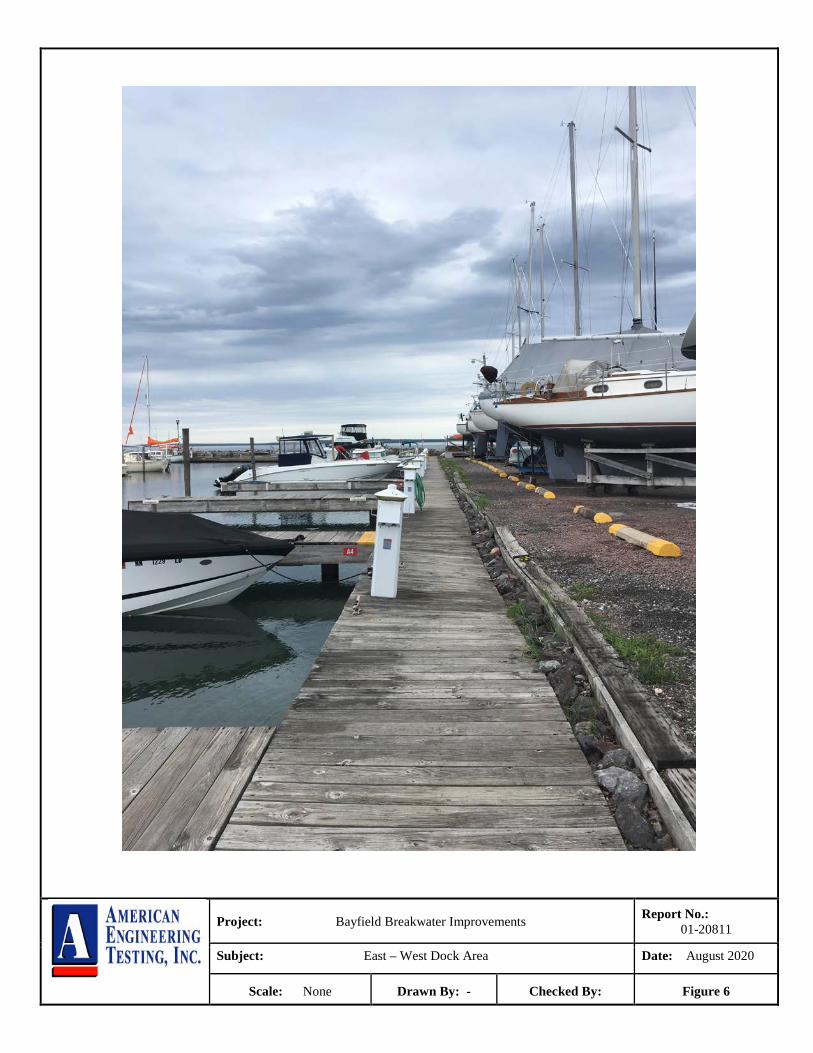
Project: Bayfield Breakwater Improvements Report No.: 01-20811
Subject: East – West Dock Area Date: August 2020
Scale: None Drawn By: - Checked By: Figure 6

Project: Bayfield Breakwater Improvements Report No.: 01-20811
Subject: Existing Breakwater Looking South Date: August 2020
Scale: None Drawn By: - Checked By: Figure 7
Report of Geotechnical Exploration Breakwater Improvements; Bayfield, WI AMERICAN August 28, 2020 ENGINEERING Report No. 01-20811 TESTING, INC.
Appendix B
Geotechnical Report Limitations and Guidelines for Use
Appendix B Geotechnical Report Limitations and Guidelines for Use
Report No. 01-20811
Appendix B – Page 1 of 3 AMERICAN ENGINEERING TESTING, INC
B.1 REFERENCE This appendix provides information to help you manage your risks relating to subsurface problems which are caused by construction delays, cost overruns, claims, and disputes. This information was developed and provided by GBA1, of which, we are a member firm. B.2 RISK MANAGEMENT INFORMATION B.2.1 Understand the Geotechnical Engineering Services Provided for this Report Geotechnical engineering services typically include the planning, collection, interpretation, and analysis of exploratory data from widely spaced borings and/or test pits. Field data are combined with results from laboratory tests of soil and rock samples obtained from field exploration (if applicable), observations made during site reconnaissance, and historical information to form one or more models of the expected subsurface conditions beneath the site. Local geology and alterations of the site surface and subsurface by previous and proposed construction are also important considerations. Geotechnical engineers apply their engineering training, experience, and judgment to adapt the requirements of the prospective project to the subsurface model(s). Estimates are made of the subsurface conditions that will likely be exposed during construction as well as the expected performance of foundations and other structures being planned and/or affected by construction activities. The culmination of these geotechnical engineering services is typically a geotechnical engineering report providing the data obtained, a discussion of the subsurface model(s), the engineering and geologic engineering assessments and analyses made, and the recommendations developed to satisfy the given requirements of the project. These reports may be titled investigations, explorations, studies, assessments, or evaluations. Regardless of the title used, the geotechnical engineering report is an engineering interpretation of the subsurface conditions within the context of the project and does not represent a close examination, systematic inquiry, or thorough investigation of all site and subsurface conditions. B.2.2 Geotechnical Engineering Services are Performed for Specific Purposes, Persons, and Projects, and At Specific Times Geotechnical engineers structure their services to meet the specific needs, goals, and risk management preferences of their clients. A geotechnical engineering study conducted for a given civil engineer will not likely meet the needs of a civil-works constructor or even a different civil engineer. Because each geotechnical engineering study is unique, each geotechnical engineering report is unique, prepared solely for the client. Likewise, geotechnical engineering services are performed for a specific project and purpose. For example, it is unlikely that a geotechnical engineering study for a refrigerated warehouse will be the same as one prepared for a parking garage; and a few borings drilled during a preliminary study to evaluate site feasibility will not be adequate to develop geotechnical design recommendations for the project. Do not rely on this report if your geotechnical engineer prepared it:
• for a different client; • for a different project or purpose; • for a different site (that may or may not include all or a portion of the original site); or • before important events occurred at the site or adjacent to it; e.g., man-made events like construction or environmental
remediation, or natural events like floods, droughts, earthquakes, or groundwater fluctuations. Note, too, the reliability of a geotechnical-engineering report can be affected by the passage of time, because of factors like changed subsurface conditions; new or modified codes, standards, or regulations; or new techniques or tools. If you are the least bit uncertain about the continued reliability of this report, contact your geotechnical engineer before applying the recommendations in it. A minor amount of additional testing or analysis after the passage of time – if any is required at all – could prevent major problems. 1 Geoprofessional Business Association, 1300 Piccard Drive, LL14, Rockville, MD 20850
Telephone: 301/565-2733: www.geoprofessional.org, 2019

Appendix B Geotechnical Report Limitations and Guidelines for Use
Report No. 01-20811
Appendix B – Page 2 of 3 AMERICAN ENGINEERING TESTING, INC
B.2.3 Read the Full Report Costly problems have occurred because those relying on a geotechnical-engineering report did not read the report in its entirety. Do not rely on an executive summary. Do not read selective elements only. Read and refer to the report in full. B.2.4 You Need to Inform Your Geotechnical Engineer About Change Your geotechnical engineer considered unique, project-specific factors when developing the scope of study behind this report and developing the confirmation-dependent recommendations the report conveys. Typical changes that could erode the reliability of this report include those that affect:
• the site’s size or shape; • the elevation, configuration, location, orientation, function or weight of the proposed structure and the desired
performance criteria; • the composition of the design team; or • project ownership.
As a general rule, always inform your geotechnical engineer of project or site changes – even minor ones – and request an assessment of their impact. The geotechnical engineer who prepared this report cannot accept responsibility or liability for problems that arise because the geotechnical engineer was not informed about developments the engineer otherwise would have considered. B.2.5 Most of the “Findings” Related in This Report Are Professional Opinions Before construction begins, geotechnical engineers explore a site’s subsurface using various sampling and testing procedures. Geotechnical engineers can observe actual subsurface conditions only at those specific locations where sampling and testing is performed. The data derived from that sampling and testing were reviewed by your geotechnical engineer, who then applied professional judgement to form opinions about subsurface conditions throughout the site. Actual sitewide-subsurface conditions may differ – maybe significantly – from those indicated in this report. Confront that risk by retaining your geotechnical engineer to serve on the design team through project completion to obtain informed guidance quickly, whenever needed. B.2.6 This Report’s Recommendations Are Confirmation-Dependent The recommendations included in this report – including any options or alternatives – are confirmation-dependent. In other words, they are not final, because the geotechnical engineer who developed them relied heavily on judgement and opinion to do so. Your geotechnical engineer can finalize the recommendations only after observing actual subsurface conditions exposed during construction. If through observation your geotechnical engineer confirms that the conditions assumed to exist actually do exist, the recommendations can be relied upon, assuming no other changes have occurred. The geotechnical engineer who prepared this report cannot assume responsibility or liability for confirmation-dependent recommendations if you fail to retain that engineer to perform construction observation. B.2.7 This Report Could Be Misinterpreted Other design professionals’ misinterpretation of geotechnical engineering reports has resulted in costly problems. Confront that risk by having your geotechnical engineer serve as a continuing member of the design team, to:
• confer with other design-team members; • help develop specifications; • review pertinent elements of other design professionals’ plans and specifications; and • be available whenever geotechnical engineering guidance is needed.
You should also confront the risk of constructors misinterpreting this report. Do so by retaining your geotechnical engineer to participate in prebid and preconstruction conferences and to perform construction-phase observations. B.2.8 Give Constructors a Complete Report and Guidance Some owners and design professionals mistakenly believe they can shift unanticipated-subsurface-conditions liability to constructors by limiting the information they provide for bid preparation. To help prevent the costly, contentious problems this practice has caused, include the complete geotechnical engineering report, along with any attachments or appendices, with your contract documents, but be certain to note conspicuously that you’ve included the material for information purposes only. To avoid misunderstanding, you may also want to note that “informational purposes” means constructors have no right to rely on the interpretations, opinions, conclusions, or recommendations in the report. Be certain that constructors know they may learn about

Appendix B Geotechnical Report Limitations and Guidelines for Use
Report No. 01-20811
Appendix B – Page 3 of 3 AMERICAN ENGINEERING TESTING, INC
specific project requirements, including options selected from the report, only from the design drawings and specifications. Remind constructors that they may perform their own studies if they want to and be sure to allow enough time to permit them to do so. Only then might you be in a position to give constructors the information available to you, while requiring them to at least share some of the financial responsibilities stemming from unanticipated conditions. Conducting prebid and preconstruction conferences can also be valuable in this respect. B.2.9 Read Responsibility Provisions Closely Some client representatives, design professionals, and constructors do not realize that geotechnical engineering is far less exact than other engineering disciplines. This happens in part because soil and rock on project sites are typically heterogeneous and not manufactured materials with well-defined engineering properties like steel and concrete. That lack of understanding has nurtured unrealistic expectations that have resulted in disappointments, delays, cost overruns, claims, and disputes. To confront that risk, geotechnical engineers commonly include explanatory provisions in their reports. Sometimes labeled “limitations,” many of these provisions indicate where geotechnical engineers’ responsibilities begin and end, to help others recognize their own responsibilities and risks. Read these provisions closely. Ask questions. Your geotechnical engineer should respond fully and frankly. B.2.10 Geoenvironmental Concerns Are Not Covered The personnel, equipment, and techniques used to perform an environmental study – e.g., a “phase-one” or “phase-two” environmental site assessment – differ significantly from those used to perform a geotechnical engineering study. For that reason, a geotechnical engineering report does not usually provide environmental findings, conclusions, or recommendations; e.g., about the likelihood of encountering underground storage tanks or regulated contaminants. Unanticipated subsurface environmental problems have led to project failures. If you have not obtained your own environmental information about the project site, ask your geotechnical consultant for a recommendation on how to find environmental risk-management guidance. B.2.11 Obtain Professional Assistance to Deal with Moisture Infiltration and Mold While your geotechnical engineer may have addressed groundwater, water infiltration, or similar issues in this report, the engineer’s services were not designed, conducted, or intended to prevent migration of moisture – including water vapor – from the soil through building slabs and walls and into the building interior, where it can cause mold growth and material-performance deficiencies. Accordingly, proper implementation of the geotechnical engineer’s recommendations will not of itself be sufficient to prevent moisture infiltration. Confront the risk of moisture infiltration by including building-envelope or mold specialists on the design team. Geotechnical engineers are not building-envelope or mold specialists.

THIS PAGE INTENTIONALLY LEFT BLANK

BIDDER ______________________
Project #00320024 Bid © 2021 MSA Professional Services, Inc. 00 41 00-1
BID 1
2
APOSTLE ISLANDS MARINA RECONSTRUCTION 3
CITY OF BAYFIELD 4
BAYFIELD COUNTY, WI 5
6
PROJECT #00320024 7
8
TABLE OF ARTICLES 9
10
Article Article 11
Number 12
13
1 Bid Recipient 14
2 Bidder’s Acknowledgements 15
3 Bidder’s Representations 16
4 Bidder’s Certification 17
5 Basis of Bid 18
6 Time of Completion 19
7 Attachments to this Bid 20
8 Defined Terms 21
9 Bid Submittal 22
23
24
25
BID FORM PROVIDED ON QUESTvBID
ONLINE BIDDING ONLY

BIDDER ______________________
Project #00320024 Bid © 2021 MSA Professional Services, Inc. 00 41 00-2
1
ARTICLE 1 - BID RECIPIENT 2
1.01 This Bid is submitted to: 3
4
QuestCDN/vBID (www.QuestCDN.com) 5
6
Access the electronic bid form by downloading the project documents and select the online 7
bidding button at the top of the advertisement. Contact Quest at (952) 233-1632 if you have 8
questions on how to upload your bid. 9
10
1.02 The undersigned BIDDER proposes and agrees, if this Bid is accepted, to enter into an 11
Agreement with OWNER in the form included in the Bidding Documents to perform all 12
Work as specified or indicated in the Bidding Documents for the prices and within the times 13
indicated in this Bid and in accordance with the other terms and conditions of the Bidding 14
Documents. 15
16
ARTICLE 2 - BIDDERS ACKNOWLEDGEMENTS 17
2.01 BIDDER accepts all of the terms and conditions of the Instructions to Bidders, including 18
without limitation those dealing with the disposition of Bid security. This Bid will remain 19
subject to acceptance for 60 days after the Bid opening, or for such longer period of time that 20
BIDDER may agree to in writing upon request of OWNER. 21
22
ARTICLE 3 - BIDDER’S REPRESENTATIONS 23
3.01 In submitting this Bid, BIDDER represents that: 24
25
A. BIDDER has examined and carefully studied the Bidding Documents, other related 26
data identified in the Bidding Documents, and the following Addenda, receipt of all 27
which is hereby acknowledged. 28
29
Addendum No. Addendum Date
30
B. BIDDER has visited the Site and become familiar with and is satisfied as to the 31
general, local and Site conditions that may affect cost, progress, and performance of 32
the Work. 33
34
C. BIDDER is familiar with and is satisfied as to all Laws and Regulations that may 35
affect cost, progress and performance of the Work. 36
37
D. BIDDER has carefully studied all: (1) reports of explorations and tests of subsurface 38
conditions at or contiguous to the Site and all drawings of physical conditions 39

BIDDER ______________________
Project #00320024 Bid © 2021 MSA Professional Services, Inc. 00 41 00-3
relating to existing surface or subsurface structures at the Site (except Underground 1
Facilities) that have been identified in SC-4.02 as containing reliable "technical 2
data," and (2) reports and drawings of Hazardous Environmental Conditions, if any, 3
at the Site that have been identified in SC-4.06 as containing reliable "technical 4
data." 5
6
E. BIDDER has considered the information known to BIDDER; information commonly 7
known to contractors doing business in the locality of the Site; information and 8
observations obtained from visits to the Site; the Bidding Documents; and the Site-9
related reports and drawings identified in the Bidding Documents, with respect to the 10
effect of such information, observations, and documents on (1) the cost, progress, 11
and performance of the Work; (2) the means, methods, techniques, sequences, and 12
procedures of construction to be employed by BIDDER, including applying the 13
specific means, methods, techniques, sequences, and procedures of construction 14
expressly required by the Bidding Documents; and (3) BIDDER’s safety precautions 15
and programs. 16
17
F. Based on the information and observations referred to in Paragraph 3.01.E above, 18
BIDDER does not consider that further examinations, investigations, explorations, 19
tests, studies, or data are necessary for the determination of this Bid for performance 20
of the Work at the price(s) bid and within the times required, and in accordance with 21
the other terms and conditions of the Bidding Documents. 22
23
G. BIDDER is aware of the general nature of work to be performed by OWNER and 24
others at the Site that relates to the Work as indicated in the Bidding Documents. 25
26
H. BIDDER has given ENGINEER written notice of all conflicts, errors, ambiguities, or 27
discrepancies that BIDDER has discovered in the Bidding Documents, and the 28
written resolution thereof by ENGINEER is acceptable to BIDDER. 29
30
I. The Bidding Documents are generally sufficient to indicate and convey 31
understanding of all terms and conditions for the performance of the Work for which 32
this Bid is submitted. 33
34
ARTICLE 4 - BIDDER’S CERTIFICATION 35
4.01 BIDDER certifies that: 36
37
A. This Bid is genuine and not made in the interest of or on behalf of any undisclosed 38
individual or entity and is not submitted in conformity with any collusive agreement 39
or rules of any group, association, organization or corporation; 40
41
B. BIDDER has not directly or indirectly induced or solicited any other BIDDER to 42
submit a false or sham Bid; 43
44
C. BIDDER has not solicited or induced any individual or entity to refrain from 45
bidding; and 46

BIDDER ______________________
Project #00320024 Bid © 2021 MSA Professional Services, Inc. 00 41 00-4
1
D. BIDDER has not engaged in corrupt, fraudulent, collusive, or coercive practices in 2
competing for the Contract. For the purposes of this Paragraph 4.01.D: 3
1. “corrupt practice” means the offering, giving, receiving, or soliciting of any 4
thing of value likely to influence the action of a public official in the bidding 5
process; 6
2. “fraudulent practice” means an intentional misrepresentation of facts made 7
(a) to influence the bidding process to the detriment of OWNER, (b) to 8
establish bid prices at artificial non-competitive levels, or (c) to deprive 9
OWNER of the benefits of free and open competition; 10
3. “collusive practice” means a scheme or arrangement between two or more 11
Bidders, with or without the knowledge of OWNER, a purpose of which is to 12
establish bid prices at artificial, non-competitive levels; and 13
4. “coercive practice” means harming or threatening to harm, directly or 14
indirectly, persons or their property to influence their participation in the 15
bidding process or affect the execution of the Contract. 16
17
E. BIDDER and all subcontractors will comply with the funding requirements for this 18
work including federal wage requirements. 19
20
ARTICLE 5 - BASIS OF BID 21
5.01 BIDDER will complete the Work in accordance with the Contract Documents for the 22
following price(s): 23
ITEM ITEM EST UNIT TOTAL
NO. DESCRIPTION QTY UNITS PRICE PRICE
BASE BID 1. Apostle Islands Marina Breakwall
Reconstruction, Complete 1 LS $_________ $____________
2. Revetment Geotextile Fabric 7,950 SY $_________ $____________
3. Armorstone W for 1.5:1 Slope 7,430 TON $_________ $____________
4. Armorstone W10 for 1.5:1 Slope 7,875 TON $_________ $____________
5. Armorstone W200 for 1.5:1 Slope 3,445 TON $_________ $____________
6. Armorstone W for 2.0:1 Slope 1,895 TON $_________ $____________
7. Armorstone W10 for 2.0:1 Slope 2,300 TON $_________ $____________
8. Armorstone W200 for 2.0:1 Slope 880 TON $_________ $____________
9. Armorstone W for 2.5:1 Slope 530 TON $_________ $____________
10. Armorstone W10 for 2.5:1 Slope 535 TON $_________ $____________
11. Armorstone W200 for 2.5:1 Slope 230 TON $_________ $____________
12. Soil Sampling 2 EACH $_________ $____________
13. Handling and Disposal of
Contaminated Soil 150 CY $_________ $____________ TOTAL: Items #1-#13
$________________________
24

BIDDER ______________________
Project #00320024 Bid © 2021 MSA Professional Services, Inc. 00 41 00-5
1
LUMP SUM BID PRICE ___________________________________________ ($__________) 2
(use words) (figures) 3
4
All specified cash allowances are included in the price(s) set forth above and have been 5
computed in accordance with Paragraph 11.02 of the General Conditions. 6
7
ARTICLE 6 - TIME OF COMPLETION 8
6.01 BIDDER agrees that the Work will be substantially completed on or before April 15, 2022 9
and will be completed and ready for final payment in accordance with Paragraph 14.07 of the 10
General Conditions on or before April 30, 2022. 11
12
6.02 BIDDER accepts the provisions of the Agreement as to liquidated damages. 13
14
ARTICLE 7 - ATTACHMENTS TO THE BID 15
7.01 The following documents are submitted with and made a condition of this Bid: 16
17
A. Required Bid security in the form of 18
19
B. List of Proposed Subcontractors 20
21
22
23
24
25
26
27
C. List of Proposed Suppliers 28
29
30
31
32
33
34
35
36
D. Evidence of authority to do business in the state of the Project; or a written covenant 37
to obtain such license within the time for acceptance of Bids; 38
39
E. Contractor’s License No.: ____________ [or] Evidence of Bidder’s ability to obtain 40
a State Contractor’s License and a covenant by BIDDER to obtain said license within 41
the time for acceptance of Bids; 42
43
F. Required Bidder Qualifications Statement with Supporting Data including full legal 44
name, prior names, legal status, organizational capabilities, and references; financial 45

BIDDER ______________________
Project #00320024 Bid © 2021 MSA Professional Services, Inc. 00 41 00-6
and performance related qualifications such as financial statements, preferred credit 1
rating agency, disputes and disciplinary actions; office from which work will be 2
performed, key personnel, proposed subcontractors, work that will be self-performed, 3
safety program, insurance and bonds; past project experience of projects similar to 4
this project including location, type, key contractor personnel, and project delivery 5
method; 6
7
G. Conflict of interest form 8
9
10
ARTICLE 8 - DEFINED TERMS 11
8.01 The terms used in this Bid with initial capital letters have the meanings stated in the 12
Instructions to Bidders, the General Conditions, and the Supplementary Conditions. 13

BIDDER ______________________
Project #00320024 Bid © 2021 MSA Professional Services, Inc. 00 41 00-7
ARTICLE 9 - BID SUBMITTAL 1
If BID is submitted by: 2
An Individual 3
Name (typed or printed): ____________________________________________________ 4
5
By:_________________________________________________________________ (SEAL) 6
(Individual’s signature) 7
Doing business as: ________________________________________________________ 8
Business address: _________________________________________________________ 9
________________________________________________________________________ 10
Phone No.:_______________ FAX No.:_______________ E-MAIL: ______________ 11
12
A Partnership 13
Partnership Name: __________________________________________________ (SEAL) 14
15
By: ______________________________________________________________ (SEAL) 16
(Signature of general partner -- attach evidence of authority to sign) 17
18
Name (typed or printed): ____________________________________________________ 19
Business address: _________________________________________________________ 20
________________________________________________________________________ 21
Phone No.:_______________ FAX No.:_______________ E-MAIL: ______________ 22
23
A Corporation 24
Corporation Name: _________________________________________________ (SEAL) 25
State of Incorporation: _____________________________________________________ 26
Type (General Business, Professional, Service, Limited Liability): __________________ 27
28
By: ______________________________________________________________ (SEAL) 29
(Signature -- attach evidence of authority to sign) 30
31
Name (typed or printed): ____________________________________________________ 32
33
Title: _______________________________ 34
(CORPORATE SEAL) 35
Attest: __________________________________________________________________ 36
(Signature -- Indicate Title of Attesting Signature) 37
38
Business address: _________________________________________________________ 39
________________________________________________________________________ 40
Phone No.:_______________ FAX No.:_______________ E-MAIL: ______________ 41
42
Date of Qualification to do business in Wisconsin is ____/____/____. 43
44

BIDDER ______________________
Project #00320024 Bid © 2021 MSA Professional Services, Inc. 00 41 00-8
A Joint Venture 1
Name of Joint Venturer: ____________________________________________________ 2
3
First Joint Venturer Name: ___________________________________________ (SEAL) 4
5
By: _____________________________________________________________________ 6
(Signature of joint venture partner -- attach evidence of authority to sign) 7
8
Name (typed or printed): ____________________________________________________ 9
10
Title: _______________________________ 11
12
Business address: _________________________________________________________ 13
________________________________________________________________________ 14
Phone No.:_______________ FAX No.:_______________ E-MAIL: ______________ 15
16
17
18
Second Joint Venturer Name: ________________________________________ (SEAL) 19
20
21
By: _____________________________________________________________________ 22
(Signature of joint venture partner -- attach evidence of authority to sign) 23
24
Name (typed or printed): ____________________________________________________ 25
26
Title: _______________________________ 27
28
(Each joint venturer must sign. The manner of signing for each individual, partnership, and 29
corporation that is a party to the joint venture should be in the manner indicated above.) 30
31
Business address: _________________________________________________________ 32
________________________________________________________________________ 33
Phone No.:_______________ FAX No.:_______________ E-MAIL: ______________ 34
35
SUBMITTED on ________________________, _____. 36
37
State Contractor License No. ____________________. (if applicable) 38
39

PENAL SUM FORM
EJCDC C-430 (2007 Edition) Prepared by the Engineers Joint Contract Documents Committee.
00 43 00 - 1
BID BOND
Any singular reference to Bidder, Surety, Owner or other party shall be considered plural where applicable.
BIDDER (Name and Address): SURETY (Name and Address of Principal Place of Business): OWNER (Name and Address): BID Bid Due Date: Description (Project Name and Include Location): BOND Bond Number: Date (Not earlier than Bid due date): Penal sum $ (Words) (Figures) Surety and Bidder, intending to be legally bound hereby, subject to the terms set forth below, do each cause this Bid Bond to be duly executed by an authorized officer, agent, or representative. BIDDER SURETY (Seal) (Seal) Bidder’s Name and Corporate Seal Surety’s Name and Corporate Seal By: By: Signature Signature (Attach Power of Attorney) Print Name Print Name Title Title Attest: Attest: Signature Signature Title Title Note: Above addresses are to be used for giving any required notice. Provide execution by any additional parties, such as joint venturers, if necessary.

PENAL SUM FORM
EJCDC C-430 (2007 Edition) Prepared by the Engineers Joint Contract Documents Committee.
00 43 00 - 2
1. Bidder and Surety, jointly and severally, bind themselves, their heirs, executors, administrators, successors, and assigns to pay to Owner upon default of Bidder the penal sum set forth on the face of this Bond. Payment of the penal sum is the extent of Bidder’s and Surety’s liability. Recovery of such penal sum under the terms of this Bond shall be Owner’s sole and exclusive remedy upon default of Bidder.
2. Default of Bidder shall occur upon the failure of Bidder to deliver within the time required by the Bidding Documents (or any extension thereof agreed to in writing by Owner) the executed Agreement required by the Bidding Documents and any performance and payment bonds required by the Bidding Documents.
3. This obligation shall be null and void if:
3.1 Owner accepts Bidder’s Bid and Bidder delivers within the time required by the Bidding Documents (or any extension thereof agreed to in writing by Owner) the executed Agreement required by the Bidding Documents and any performance and payment bonds required by the Bidding Documents, or
3.2 All Bids are rejected by Owner, or
3.3 Owner fails to issue a Notice of Award to Bidder within the time specified in the Bidding Documents (or any extension thereof agreed to in writing by Bidder and, if applicable, consented to by Surety when required by Paragraph 5 hereof).
4. Payment under this Bond will be due and payable upon default of Bidder and within 30 calendar days after receipt by Bidder and Surety of written notice of default from Owner, which notice will be given with reasonable promptness, identifying this Bond and the Project and including a statement of the amount due.
5. Surety waives notice of any and all defenses based on or arising out of any time extension to issue Notice of Award agreed to in writing by Owner and Bidder, provided that the total time for issuing Notice of Award including extensions shall not in the aggregate exceed 120 days from Bid due date without Surety’s written consent.
6. No suit or action shall be commenced under this Bond prior to 30 calendar days after the notice of default required in Paragraph 4 above is received by Bidder and Surety and in no case later than one year after Bid due date.
7. Any suit or action under this Bond shall be commenced only in a court of competent jurisdiction located in the state in which the Project is located.
8. Notices required hereunder shall be in writing and sent to Bidder and Surety at their respective addresses shown on the face of this Bond. Such notices may be sent by personal delivery, commercial courier, or by United States Registered or Certified Mail, return receipt requested, postage pre-paid, and shall be deemed to be effective upon receipt by the party concerned.
9. Surety shall cause to be attached to this Bond a current and effective Power of Attorney evidencing the authority of the officer, agent, or representative who executed this Bond on behalf of Surety to execute, seal, and deliver such Bond and bind the Surety thereby.
10. This Bond is intended to conform to all applicable statutory requirements. Any applicable requirement of any applicable statute that has been omitted from this Bond shall be deemed to be included herein as if set forth at length. If any provision of this Bond conflicts with any applicable statute, then the provision of said statute shall govern and the remainder of this Bond that is not in conflict therewith shall continue in full force and effect.
11. The term “Bid” as used herein includes a Bid, offer, or proposal as applicable.

Project #00320024 Appendix F – Davis-Bacon Requirements © 2021 MSA Professional Services, Inc.
00 43 00-1
Conflict of Interest Form for Funding Requirements 1
Appendix F - Davis-Bacon Requirements 2 3
4

THIS PAGE INTENTIONALLY LEFT BLANK

POTENTIAL CONFLICT OF INTEREST DISCLOSURE
Potential Conflict of Interest Disclosure Page 1 Revised: February 4, 2021
Funding Sources:ARMY CORPS OF ENGINEERS SECTION 154 PROGRAM
WISCONSIN DEPARTMENT OF TRANSPORTATION HARBOR ASSISTANCE PROGRAMAPOSTLE ISLANDS MARINA BREAKWATER IMPROVEMENT PROJECT
CITY OF BAYFIELD, WISCONSIN
Do you have family or business ties to any of the people listed below?Yes No
If yes, please check the box next to the name(s) of the individual(s) and describe therelationship in the space provided adjacent to the name or on the next page:
ELECTED OFFICIALS:
Gordon T. Ringberg, Mayor
James Bryan, Council, District 1, Chair – Harbor Commission
Sheryl Burkel, Council, District 2
Joanne Cirillo, Council, District 3
Matt Carrier, Council, District 4
<INSERT FULL NAME AND TITLE OF OTHER ELECTED OFFICIAL>
<INSERT FULL NAME AND TITLE OF OTHER ELECTED OFFICIAL>
CITY ADMINISTRATION, DEPARTMENT HEADS AND LEGAL COUNSEL:
Billie Hoopman, City Clerk
Dionne Johnston, Treasurer
Tom Kovachevich, Public Works Director
Sarah Mather, Utility Clerk
Colleen Daly, City Attorney
Terry Bauer, Harbor Commission
Michelle Shrider, Harbor Commission
Ted Dougherty, Harbor Commission
Matthew Zawislak, Harbor Commission

POTENTIAL CONFLICT OF INTEREST DISCLOSURE
Potential Conflict of Interest Disclosure Page 2 Revised: February 4, 2021
ENGINEERING AND CONSULTING FIRM(S):
Bruce Lunde, P.E., Senior Project Manager, MSA Professional Services, Inc.
Mary Wagner, P.E., M.A.-I., Funding Administrator, Municipal Advisor Principal, MSA
Professional Services, Inc.
Krista Sommerfeldt, P.E., Senior Project Engineer, MSA Professional Services, Inc.
Russ Jensen, P.E., Team Leader, Senior Project Engineer, MSA Professional Services,
Inc.
Kyle Busch, P.E., Project Engineer, MSA Professional Services, Inc.
Description of Relationship(s) IF ANY: If more than one name is checked, please itemize.
Please Note: The name of any bidder with a potential conflict of interest will be disclosed atthe City Council meeting in which bids are discussed. Potential conflicts of interest will bereviewed in accordance with legal counsel and the local, state and federal entities.
Printed Name of Individual Title Signature
Name of Business/Firm/Company Date Signed [MM/DD/YYYY]

Appendix F
3. Contract and Subcontract provisions. (a) The Recipient shall insure that the subrecipient (s) shall insert in full in any contract in excess of$2,000 which is entered into for the actual construction, alteration and/or repair, including painting anddecorating, of a public building or public work, or building or work financed in whole or in part fromFederal funds or in accordance with guarantees of a Federal agency ("AGENCY") or financed from funds
obtained by pledge of any contract of a Federal agency to make a loan, grant or annual contribution (ex-cept where a different meaning is expressly indicated), and which is subject to the labor standards provi-sions of any of the acts listed in § 5.1, the following clauses: (1) Minimum wages. (i) All laborers and mechanics employed or working upon the site of the work will be paid unconditionally and not less often than once a week, and without subsequent deduction or rebate on any account (except such payroll deductions as are permitted by regulations issued by the Secretary of Labor under the Copeland Act (29 CFR part 3) ), the full amount of wages and bona fide fringe benefits (or cash equivalents thereof) due at time of payment computed at rates not less than those contained in the wage determination of the Secretary of Labor which is attached hereto and made a part hereof, regardless of any contractual relationship which may be alleged to exist between the contractor and such laborers and mechanics. Contributions made or costs reasonably anticipated for bona fide fringe benefits under section 1(b)(2) of the Davis-Bacon Act on behalf of laborers or mechanics are considered wages paid to such laborers or mechanics, subject to the provisions of paragraph (a)(1)(iv) of this section; also, regular contributions made or costs incurred for more than a weekly period (but not less often than quarterly) under plans, funds, or programs which cover the particular weekly period, are deemed to be constructively made or incurred during such weekly period. Such laborers and mechanics shall be paid the appropriate wage rate and fringe benefits on the wage determination for the classification of work actually performed, without regard to skill, except as provided in § 5.5(a)(4). Laborers or mechanics performing work in more than one classification may be compensated at the rate specified for each classification for the time actually worked therein: Provided, That the employer's payroll records accurately set forth the time spent in each classification in which work is performed. The wage determination (including any additional classification and wage rates conformed under paragraph (a)(1)(ii) of this section) and the Davis-Bacon poster (WH-1321) shall be posted at all times by the contractor and its subcontractors at the site of the work in a prominent and accessible place where it can be easily seen by the workers. Subrecipient s may obtain wage determinations from the U.S. Department of Labor’s web site, www.wdol.gov. (ii)(A) The subrecipient (s), on behalf of AGENCY, shall require that any class of laborers or me-chanics,

including helpers, which is not listed in the wage determination and which is to be employed under thecontract shall be classified in conformance with the wage determination. The AGENCY award official
shall approve an additional classification and wage rate and fringe benefits therefore only when the fol-lowing criteria have been met: (1) The work to be performed by the classification requested is not performed by a classification in the wage determination; and (2) The classification is utilized in the area by the construction industry; and (3) The proposed wage rate, including any bona fide fringe benefits, bears a reasonable relationship to the wage rates contained in the wage determination. (B) If the contractor and the laborers and mechanics to be employed in the classification (if known), or their representatives, and the subrecipient (s) agree on the classification and wage rate (including the amount designated for fringe benefits where appropriate), a report of the action taken shall be sent by the subrecipient (s) to the State award official. The State award official will transmit the report, to the Administrator of the Wage and Hour Division, Employment Standards Administration, U.S. Department of Labor, Washington, DC 20210. The Administrator, or an authorized representative, will approve, modify, or disapprove every additional classification action within 30 days of receipt and so advise the State award official or will notify the State award official within the 30-day period that additional time is necessary. (C) In the event the contractor, the laborers or mechanics to be employed in the classification or their representatives, and the and the subrecipient (s) do not agree on the proposed classification and wage rate (including the amount designated for fringe benefits, where appropriate), the award official shall refer the questions, including the views of all interested parties and the recommendation of the State award official, to the Administrator for determination. The Administrator, or an authorized representative, will issue a determination within 30 days of receipt and so advise the contracting officer or will notify the contracting officer within the 30-day period that additional time is necessary. (D) The wage rate (including fringe benefits where appropriate) determined pursuant to paragraphs (a)(1)(ii)(B) or (C) of this section, shall be paid to all workers performing work in the classification under this contract from the first day on which work is performed in the classification. (iii) Whenever the minimum wage rate prescribed in the contract for a class of laborers or mechanics includes a fringe benefit which is not expressed as an hourly rate, the contractor shall either pay the benefit as stated in the wage determination or shall pay another bona fide fringe benefit or an hourly cash equivalent thereof. (iv) If the contractor does not make payments to a trustee or other third person, the contractor may
consider as part of the wages of any laborer or mechanic the amount of any costs reasonably anticipated in providing bona fide fringe benefits under a plan or program, Provided, That the Secretary of Labor has found, upon the written request of the contractor, that the applicable standards of the Davis-Bacon Act have been met. The Secretary of Labor may require the contractor to set aside in a separate account assets for the meeting of obligations under the plan or program. (2) Withholding. The subrecipient (s), shall upon written request of the AGENCY Award Official or an au-thorized representative of the Department of Labor, withhold or cause to be withheld from the con-tractor under this contract or any other Federal contract with the same prime contractor, or any other federally-assisted contract subject to Davis-Bacon prevailing wage requirements, which is held by the same prime contractor, so much of the accrued payments or advances as may be considered necessary to pay laborers and mechanics, including apprentices, trainees, and helpers, employed by the contrac-tor or any subcontractor the full amount of wages required by the contract. In the event of failure to pay any laborer or mechanic, including any apprentice, trainee, or helper, employed or working on the site of the work, all or part of the wages required by the contract, the AGENCY may, after written notice to the contractor, sponsor, applicant, or owner, take such action as may be necessary to cause the sus-pension of any further payment, advance, or guarantee of funds until such violations have ceased.
(3) Payrolls and basic records. (i) Payrolls and basic records relating thereto shall be maintained by the contractor during the course of the work and preserved for a period of three years thereafter for all laborers and mechanics working at the site of the work. Such records shall contain the name, address, and social security number of each such worker, his or her correct classification, hourly rates of wages paid (including rates of contributions or costs anticipated for bona fide fringe benefits or cash equivalents thereof of the types described in section 1(b)(2)(B) of the Davis-Bacon Act), daily and weekly number of hours worked, deductions made and actual wages paid. Whenever the Secretary of Labor has found under 29 CFR 5.5(a)(1)(iv) that the wages of any laborer or mechanic include the amount of any costs reasonably anticipated in providing benefits under a plan or program described in section 1(b)(2)(B) of the Davis-Bacon Act, the contractor shall maintain records which show that the commitment to provide such benefits is enforceable, that the plan or program is financially responsible, and that the plan or program has been communicated in writing to the laborers or mechanics affected, and records which show the costs anticipated or the actual cost incurred in providing such benefits. Contractors employing apprentices or trainees under approved programs shall maintain written evidence of the registration of apprenticeship programs and certification of trainee programs, the registration of the apprentices and trainees, and the ratios and wage rates prescribed in the applicable programs. (ii)(A) The contractor shall submit weekly, for each week in which any contract work is performed, a copy of all payrolls to the subrecipient , that is, the entity that receives the sub-grant or loan from the State capitalization grant recipient. Such documentation shall be available on request of the State

recipient or the AGENCY. As to each payroll copy received, the subrecipient shall provide written confirma-tion in a form satisfactory to the State indicating whether or not the project is in compliance with therequirements of 29 CFR 5.5(a)(1) based on the most recent payroll copies for the specified week. The pay-rolls shall set out accurately and completely all of the information required to be maintained under 29 CFR 5.5(a)(3)(i), except that full social security numbers and home addresses shall not be included on the weekly payrolls. Instead the payrolls shall only need to include an individually identifying numberfor each employee (e.g., the last four digits of the employee's social security number). The required weekly payroll information may be submitted in any form desired. Optional Form WH-347 is availablefor this purpose from the Wage and Hour Division Web site athttp://www.dol.gov/esa/whd/forms/wh347instr.htm or its successor site. The prime contractor isresponsible for the submission of copies of payrolls by all subcontractors. Contractors andsubcontractors shall maintain the full social security number and current address of each covered worker, and shall provide them upon request to the subrecipient (s) for transmission to the State or AGENCYif requested by the AGENCY , the State, the contractor, or the Wage and Hour Division of the Department
of Labor for purposes of an investigation or audit of compliance with prevailing wage requirements. It isnot a violation of this section for a prime contractor to require a subcontractor to provide addresses andsocial security numbers to the prime contractor for its own records, without weekly submission to thesubrecipient (s). (B) Each payroll submitted shall be accompanied by a “Statement of Compliance,” signed by the contractor or subcontractor or his or her agent who pays or supervises the payment of the persons employed under the contract and shall certify the following: (1) That the payroll for the payroll period contains the information required to be provided under § 5.5 (a)(3)(ii) of Regulations, 29 CFR part 5, the appropriate information is being maintained under § 5.5 (a)(3)(i) of Regulations, 29 CFR part 5, and that such information is correct and complete; (2) That each laborer or mechanic (including each helper, apprentice, and trainee) employed on the contract during the payroll period has been paid the full weekly wages earned, without rebate, either directly or indirectly, and that no deductions have been made either directly or indirectly from the full wages earned, other than permissible deductions as set forth in Regulations, 29 CFR part 3; (3) That each laborer or mechanic has been paid not less than the applicable wage rates and fringe benefits or cash equivalents for the classification of work performed, as specified in the applicable wage determination incorporated into the contract. (C) The weekly submission of a properly executed certification set forth on the reverse side of Optional Form WH-347 shall satisfy the requirement for submission of the “Statement of Compliance” required by paragraph (a)(3)(ii)(B) of this section. (D) The falsification of any of the above certifications may subject the contractor or subcontractor to civil or criminal prosecution under section 1001 of title 18 and section 231 of title 31 of the United
States Code. (iii) The contractor or subcontractor shall make the records required under paragraph (a)(3)(i) of thissection available for inspection, copying, or transcription by authorized representatives of the State, AGENCY or the Department of Labor, and shall permit such representatives to interview employees dur-
ing working hours on the job. If the contractor or subcontractor fails to submit the required records or tomake them available, the Federal AGENCY or State may, after written notice to the contractor, sponsor,
applicant, or owner, take such action as may be necessary to cause the suspension of any further pay-ment, advance, or guarantee of funds. Furthermore, failure to submit the required records upon request or to make such records available may be grounds for debarment action pursuant to 29 CFR
5.12. (4) Apprentices and trainees-- (i) Apprentices. Apprentices will be permitted to work at less than the predetermined rate for the work they performed when they are employed pursuant to and individually registered in a bona fide apprenticeship program registered with the U.S. Department of Labor, Employment and Training Administration, Office of Apprenticeship Training, Employer and Labor Services, or with a State Apprenticeship Agency recognized by the Office, or if a person is employed in his or her first 90 days of probationary employment as an apprentice in such an apprenticeship program, who is not individually registered in the program, but who has been certified by the Office of Apprenticeship Training, Employer and Labor Services or a State Apprenticeship Agency (where appropriate) to be eligible for probationary employment as an apprentice. The allowable ratio of apprentices to journeymen on the job site in any craft classification shall not be greater than the ratio permitted to the contractor as to the entire work force under the registered program. Any worker listed on a payroll at an apprentice wage rate, who is not registered or otherwise employed as stated above, shall be paid not less than the applicable wage rate on the wage determination for the classification of work actually performed. In addition, any apprentice performing work on the job site in excess of the ratio permitted under the registered program shall be paid not less than the applicable wage rate on the wage determination for the work actually performed. Where a contractor is performing construction on a project in a locality other than that in which its program is registered, the ratios and wage rates (expressed in percentages of the journeyman's hourly rate) specified in the contractor's or subcontractor's registered program shall be observed. Every apprentice must be paid at not less than the rate specified in the registered program for the apprentice's level of progress, expressed as a percentage of the journeymen hourly rate specified in the applicable wage determination. Apprentices shall be paid fringe benefits in accordance with the provisions of the apprenticeship program. If the apprenticeship program does not specify fringe benefits, apprentices must be paid the full amount of fringe benefits listed on the wage determination for the applicable classification. If the Administrator determines that a different practice prevails for the applicable apprentice classification, fringes shall be paid in accordance with that determination. In the event the Office of Apprenticeship Training, Employer and Labor Services, or a State Apprenticeship Agency recognized by the Office, withdraws approval of an apprenticeship program, the contractor will no longer be permitted to utilize apprentices at less than the applicable predetermined rate for the

work performed until an acceptable program is approved. (ii) Trainees. Except as provided in 29 CFR 5.16, trainees will not be permitted to work at less than the predetermined rate for the work performed unless they are employed pursuant to and individually registered in a program which has received prior approval, evidenced by formal certification by the U.S. Department of Labor, Employment and Training Administration. The ratio of trainees to journeymen on the job site shall not be greater than permitted under the plan approved by the Employment and Training Administration. Every trainee must be paid at not less than the rate specified in the approved program for the trainee's level of progress, expressed as a percentage of the journeyman hourly rate specified in the applicable wage determination. Trainees shall be paid fringe benefits in accordance with the provisions of the trainee program. If the trainee program does not mention fringe benefits, trainees shall be paid the full amount of fringe benefits listed on the wage determination unless the Administrator of the Wage and Hour Division determines that there is an apprenticeship program associated with the corresponding journeyman wage rate on the wage determination which provides for less than full fringe benefits for apprentices. Any employee listed on the payroll at a trainee rate who is not registered and participating in a training plan approved by the Employment and Training Administration shall be paid not less than the applicable wage rate on the wage determination for the classification of work actually performed. In addition, any trainee performing work on the job site in excess of the ratio permitted under the registered program shall be paid not less than the applicable wage rate on the wage determination for the work actually performed. In the event the Employment and Training Administration withdraws approval of a training program, the contractor will no longer be permitted to utilize trainees at less than the applicable predetermined rate for the work performed until an acceptable program is approved. (iii) Equal employment opportunity. The utilization of apprentices, trainees and journeymen under this part shall be in conformity with the equal employment opportunity requirements of Executive Order 11246, as amended, and 29 CFR part 30. (5) Compliance with Copeland Act requirements. The contractor shall comply with the requirements of 29 CFR part 3, which are incorporated by reference in this contract. (6) Subcontracts. The contractor or subcontractor shall insert in any subcontracts the clauses containedin 29 CFR 5.5(a)(1) through (10) and such other clauses as the AGENCY determines may by appropriate,
and also a clause requiring the subcontractors to include these clauses in any lower tier subcontracts. The prime contractor shall be responsible for the compliance by any subcontractor or lower tier sub-contractor with all the contract clauses in 29 CFR 5.5. (7) Contract termination: debarment. A breach of the contract clauses in 29 CFR 5.5 may be grounds for termination of the contract, and for debarment as a contractor and a subcontractor as provided in 29 CFR 5.12. (8) Compliance with Davis-Bacon and Related Act requirements. All rulings and interpretations of the

Davis-Bacon and Related Acts contained in 29 CFR parts 1, 3, and 5 are herein incorporated by reference in this contract. (9) Disputes concerning labor standards. Disputes arising out of the labor standards provisions of thiscontract shall not be subject to the general disputes clause of this contract. Such disputes shall beresolved in accordance with the procedures of the Department of Labor set forth in 29 CFR parts 5, 6,and 7. Disputes within the meaning of this clause include disputes between the contractor (or any of itssubcontractors) and Subrecipient (s), State, AGENCY, the U.S. Department of Labor, or the employees
or their representatives. (10) Certification of eligibility. (i) By entering into this contract, the contractor certifies that neither it (nor he or she) nor any person or firm who has an interest in the contractor's firm is a person or firm ineligible to be awarded Government contracts by virtue of section 3(a) of the Davis-Bacon Act or 29 CFR 5.12(a)(1). (ii) No part of this contract shall be subcontracted to any person or firm ineligible for award of a Government contract by virtue of section 3(a) of the Davis-Bacon Act or 29 CFR 5.12(a)(1). (iii) The penalty for making false statements is prescribed in the U.S. Criminal Code, 18 U.S.C. 1001. 4. Contract Provision for Contracts in Excess of $100,000. (a) Contract Work Hours and Safety Standards Act. The subrecipient shall insert the following clauses set forth in paragraphs (a)(1), (2), (3), and (4) of this section in full in any contract in an amount in excess of $100,000 and subject to the overtime provisions of the Contract Work Hours and Safety Standards Act. These clauses shall be inserted in addition to the clauses required by Item 3, above or 29 CFF 4.6 . As used in this paragraph, the terms laborers and mechanics include watchmen and guards. (1) Overtime requirements. No contractor or subcontractor contracting for any part of the contract work which may require or involve the employment of laborers or mechanics shall require or permit any such laborer or mechanic in any workweek in which he or she is employed on such work to work in excess of forty hours in such workweek unless such laborer or mechanic receives compensation at a rate not less than one and one-half times the basic rate of pay for all hours worked in excess of forty hours in such workweek. (2) Violation; liability for unpaid wages; liquidated damages. In the event of any violation of the clause set forth in paragraph (a)(1) of this section the contractor and any subcontractor responsible therefor shall be liable for the unpaid wages. In addition, such contractor and subcontractor shall be liable to the United States (in the case of work done under contract for the District of Columbia or a territory, to such District or to such territory), for liquidated damages. Such liquidated damages shall be computed with respect to each individual laborer or mechanic, including watchmen and guards, employed in violation

of the clause set forth in paragraph (a)(1) of this section, in the sum of $10 for each calendar day on which such individual was required or permitted to work in excess of the standard workweek of forty hours without payment of the overtime wages required by the clause set forth in paragraph (a)(1) of this section. (3) Withholding for unpaid wages and liquidated damages. The subrecipient, upon written request ofthe AGENCY Award Official or an authorized representative of the Department of Labor, shall with-
hold or cause to be withheld, from any moneys payable on account of work performed by the con-tractor or subcontractor under any such contract or any other Federal contract with the same prime contractor, or any other federally-assisted contract subject to the Contract Work Hours and Safety Standards Act, which is held by the same prime contractor, such sums as may be determined to be necessary to satisfy any liabilities of such contractor or subcontractor for unpaid wages and liqui-dated damages as provided in the clause set forth in paragraph (b)(2) of this section.
(4) Subcontracts. The contractor or subcontractor shall insert in any subcontracts the clauses set forth in paragraph (a)(1) through (4) of this section and also a clause requiring the subcontractors to include these clauses in any lower tier subcontracts. The prime contractor shall be responsible for compliance by any subcontractor or lower tier subcontractor with the clauses set forth in paragraphs (a)(1) through (4) of this section. (b) In addition to the clauses contained in Item 3, above, in any contract subject only to the Contract Work Hours and Safety Standards Act and not to any of the other statutes cited in 29 CFR 5.1, the Subrecipient shall insert a clause requiring that the contractor or subcontractor shall maintain payrolls and basic payroll records during the course of the work and shall preserve them for a period of three years from the completion of the contract for all laborers and mechanics, including guards and watchmen, working on the contract. Such records shall contain the name and address of each such employee, social security number, correct classifications, hourly rates of wages paid, daily and weekly number of hours worked, deductions made, and actual wages paid. Further, the Subrecipient shall insert in any such contract a clause providing hat the records to be maintained under this paragraph shall be made available by the contractor or subcontractor for inspection, copying, or transcription by authorized representatives of the (write the name of agency) and the Department of Labor, and the contractor or subcontractor will permit such representatives to interview employees during working hours on the job.

EJCDC C-510 (2007 Edition) 00 51 00-1 Prepared by the Engineers Joint Contract Documents Committee and endorsed by the Construction Specifications Institute.
NOTICE OF AWARD Date: Project:
Owner:
Owner's Contract No.:
Contract:
Engineer's Project No.:
Bidder:
Bidder's Address: [send Notice of Award Certified Mail, Return Receipt Requested]
You are notified that your Bid dated _____________ for the above Contract has been considered. You are the Successful Bidder and are awarded a Contract for
[Indicate total Work, alternates, or sections of Work awarded.]
The Contract Price of your Contract is
Dollars ($ ).
[Insert appropriate data if unit prices are used. Change language for cost-plus contracts.]
__ copies of the proposed Contract Documents (except Drawings) accompany this Notice of Award.
__ sets of the Drawings will be delivered separately or otherwise made available to you immediately.
You must comply with the following conditions precedent within [15] days of the date you receive this Notice of Award.
1. Deliver to the Owner [ _ ] fully executed counterparts of the Contract Documents.
2. Deliver with the executed Contract Documents the Contract security [Bonds] as specified in the Instructions to Bidders (Article 20), General Conditions (Paragraph 5.01), and Supplementary Conditions (Paragraph SC-5.01).
3. Other conditions precedent: Failure to comply with these conditions within the time specified will entitle Owner to consider you in default, annul this Notice of Award, and declare your Bid security forfeited.
Within ten days after you comply with the above conditions, Owner will return to you one fully executed counterpart of the Contract Documents.
Owner By: Authorized Signature Title Copy to Engineer

THIS PAGE INTENTIONALLY LEFT BLANK

Project #00320024 Agreement © 2021 MSA Professional Services, Inc. 00 52 00-1
AGREEMENT
THIS AGREEMENT is by and between CITY OF BAYFIELD (hereinafter called OWNER) and
_________________________________________ (hereinafter called CONTRACTOR).
OWNER and CONTRACTOR, hereby agree as follows:
ARTICLE 1 - WORK
1.01 CONTRACTOR shall complete all Work as specified or indicated in the Contract
Documents. The Work is generally described as follows: Apostle Islands Marina
Reconstruction, City of Bayfield , Bayfield County, WI.
ARTICLE 2 - THE PROJECT
2.01 The Project for which the Work under the Contract Documents may be the whole or only a
part is generally described as follows: Apostle Islands Marina Reconstruction, City of
Bayfield , Bayfield County, WI.
ARTICLE 3 - ENGINEER
3.01 The Project has been designed by MSA Professional Services, Inc., 1230 South Blvd.,
Baraboo, WI 53913 which is to act as OWNER’s representative, assume all duties and
responsibilities, and have the rights and authority assigned to Engineer in the Contract
Documents in connection with the completion of the Work in accordance with the Contract
Documents.
ARTICLE 4 - CONTRACT TIMES
4.01 Time of the Essence
A. All time limits for Milestones, if any, Substantial Completion, and completion and
readiness for final payment as stated in the Contract Documents are of the essence of
the Contract.
4.02 Dates for Substantial Completion and Final Payment
A. The Work will be substantially completed on or before April 15, 2022 and completed
and ready for final payment in accordance with Paragraph 14.07 of the General
Conditions on or before April 30, 2022.
4.03 Liquidated Damages
A. CONTRACTOR and OWNER recognize that time is of the essence as stated in
Paragraph 4.01 above and that OWNER will suffer financial loss if the Work is not

Project #00320024 Agreement © 2021 MSA Professional Services, Inc. 00 52 00-2
completed within the times specified in Paragraph 4.02 above, plus any extensions
thereof allowed in accordance with Article 12 of the General Conditions. The parties
also recognize the delays, expense and difficulties involved in proving in a legal or
arbitration proceeding the actual loss suffered by OWNER if the Work is not
completed on time. Accordingly, instead of requiring any such proof, OWNER and
CONTRACTOR agree that as liquidated damages for delay (but not as a penalty)
CONTRACTOR shall pay OWNER $500 for each day that expires after the time
specified in Paragraph 4.02 above for Substantial Completion until the Work is
substantially complete. After Substantial Completion, if CONTRACTOR shall
neglect, refuse or fail to complete the remaining Work within the Contract Time or
any proper extension thereof granted by OWNER, CONTRACTOR shall pay
OWNER $500 for each day that expires after the time specified in Paragraph 4.02
above for completion and readiness for final payment until the Work is completed
and ready for final payment.
ARTICLE 5 - CONTRACT PRICE
5.01 OWNER shall pay CONTRACTOR for completion of the Work in accordance with the
Contract Documents an amount in current funds equal to the sum of the amounts determined
pursuant to Paragraph 5.01.A. and 5.01.B below:
A. For all Work other than Unit Price Work, a lump sum of:
_______________________________________________________ ($__________)
(use words) (figure)
All specific cash allowances are included in the price in accordance with
Paragraph 11.02 of the General Conditions.
B. For all Work, at the prices stated in Contractor’s Bid, attached hereto as an exhibit.
ARTICLE 6 - PAYMENT PROCEDURES
6.01 Submittal and Processing of Payments
A. CONTRACTOR shall submit Applications for Payment 10 working days before the
end of the month in accordance with Article 14 of the General Conditions.
Applications for Payment will be processed by ENGINEER as provided in the
General Conditions.
6.02 Progress Payments; Retainage
A. OWNER shall make progress payments on account of the Contract Price on the basis
of CONTRACTOR’s Applications for Payment on or about the [last day of the
month following the month of submittal of the Application for Payment, as provided
in Paragraphs 6.02.A.1 below. All such payments will be measured by the schedule
of values established as provided in Paragraph 2.07.A of the General Conditions (and

Project #00320024 Agreement © 2021 MSA Professional Services, Inc. 00 52 00-3
in the case of Unit Price Work based on the number of units completed) or, in the
event there is no schedule of values, as provided in Division 01-General
Requirements.
1. Prior to Substantial Completion, progress payments will be made in an
amount equal to the percentage indicated below but, in each case, less the
aggregate of payments previously made and less such amounts as
ENGINEER may determine or OWNER may withhold, including but not
limited to liquidated damages, in accordance with Paragraph 14.02 of the
General Conditions.
a. 95% of Work completed (with the balance being retainage). If the
Work has been 50% completed as determined by ENGINEER, and if
the character and progress of the Work have been satisfactory to
OWNER and ENGINEER, then as long as the character and progress
of the Work remain satisfactory to OWNER and ENGINEER, there
will be no additional retainage; and
b. Estimates may include any fabricated or manufactured materials and
components specified, previously paid for by the CONTRACTOR
and delivered to the work or properly stored and suitable for
incorporation in the work embraced in the contract. Invoices
showing the amount of the fabricated or manufactured materials and
components specified must be submitted with proof of payment by
the CONTRACTOR prior to being considered for payment.
Retainage shall be as outlined in paragraph 6.02.A.1.a. above.
B. Upon Substantial Completion, OWNER shall pay an amount sufficient to increase
total payments to CONTRACTOR to 97.5% of the Work completed, less such
amounts as ENGINEER shall determine in accordance with Paragraph 14.02.B.5 of
the General Conditions and less 100% of ENGINEER’s estimate of the value of
Work to be completed or corrected as shown on the tentative list of items to be
completed or corrected attached to the certificate of Substantial Completion.
6.03 Final Payment
A. Upon final completion and acceptance of the Work in accordance with Paragraph
14.07 of the General Conditions, OWNER shall pay the remainder of the Contract
Price as recommended by ENGINEER as provided in said Paragraph 14.07.
ARTICLE 7 - INTEREST
7.01 All moneys not paid when due as provided in Article 14 of the General Conditions shall bear
interest at the rate of 5.0% per annum.

Project #00320024 Agreement © 2021 MSA Professional Services, Inc. 00 52 00-4
ARTICLE 8 - CONTRACTOR’S REPRESENTATIONS
8.01 In order to induce OWNER to enter into this Agreement, CONTRACTOR makes the
following representations:
A. CONTRACTOR has examined and carefully studied the Contract Documents and the
other related data identified in the Bidding Documents.
B. CONTRACTOR has visited the Site and become familiar with and is satisfied as to
the general, local, and Site conditions that may affect cost, progress, and performance
of the Work.
C. CONTRACTOR is familiar with and is satisfied as to all federal, state, and local
Laws and Regulations that may affect cost, progress, and performance of the work.
D. CONTRACTOR has carefully studied all: (1) reports of explorations and tests of
subsurface conditions at or contiguous to the Site and all drawings of physical
conditions relating to existing surface or subsurface structures at the Site (except
Underground Facilities), if any, that have been identified in Paragraph SC-4.02 of the
Supplementary Conditions as containing reliable "technical data," and (2) reports and
drawings of Hazardous Environmental Conditions, if any, at the Site that have been
identified in Paragraph SC-4.06 of the Supplementary Conditions as containing
reliable "technical data."
E. CONTRACTOR has considered the information known to Contractor; information
commonly known to contractors doing business in the locality of the Site;
information and observations obtained from visits to the Site; the Contract
Documents; and the Site-related reports and drawings identified in the Contract
Documents, with respect to the effect of such information, observations, and
documents on (1) the cost, progress, and performance of the Work; (2) the means,
methods, techniques, sequences, and procedures of construction to be employed by
CONTRACTOR, including any specific means, methods, techniques, sequences, and
procedures of construction expressly required by the Contract Documents; and (3)
CONTRACTOR’s safety precautions and programs.
F. Based on the information and observations referred to in Paragraph 8.01.E above,
CONTRACTOR does not consider that further examinations, investigations,
explorations, tests, studies, or data are necessary for the performance of the Work at
the Contract Price, within the Contract Times, and in accordance with the other terms
and conditions of the Contract Documents.
G. CONTRACTOR is aware of the general nature of work to be performed by OWNER
and others at the Site that relates to the Work as indicated in the Contract Documents.
H. CONTRACTOR has given ENGINEER written notice of all conflicts, errors,
ambiguities, or discrepancies that CONTRACTOR has discovered in the Contract

Project #00320024 Agreement © 2021 MSA Professional Services, Inc. 00 52 00-5
Documents, and the written resolution thereof by ENGINEER is acceptable to
CONTRACTOR.
I. The Contract Documents are generally sufficient to indicate and convey
understanding of all terms and conditions for performance and furnishing of the
Work.
ARTICLE 9 - CONTRACT DOCUMENTS
9.01 Contents
A. The Contract Documents consist of the following:
1. This Agreement (pages 00 52 00-1 to 00 52 00-8, inclusive).
2. Performance Bond (pages 00 61 13.13-1 to 00 61 13.13-3, inclusive).
3. Payment Bond (pages 00 61 13.16-1 to 00 61 13.16-3, inclusive).
4. General Conditions (pages 00 72 00-1 to 00 72 00-68, inclusive).
5. Supplementary Conditions (pages 00 73 00-1 to 00 73 00-9, inclusive).
6. Appendix F - Davis-Bacon Requirements
7. Federal Wage Rate Determinations for Bayfield County, Wisconsin;
Construction Type(s) – WI2020015, WI20210010, current as of the bid date.
8. The following which may be delivered or issued on or after the Effective
Date of the Agreement and are not attached hereto:
a. Notice to Proceed (pages 00 55 00-1, inclusive).
b. Written Amendment(s);
c. Work Change Directive(s);
d. Change Order(s).
e. Field Order(s).
B. The documents listed in Paragraphs 9.01.A are attached to this Agreement (except as
expressly noted otherwise above).
C. There are no Contract Documents other than those listed above in this Article 9.
D. The Contract Documents may only be amended, modified, or supplemented as
provided in Paragraph 3.04 of the General Conditions.

Project #00320024 Agreement © 2021 MSA Professional Services, Inc. 00 52 00-6
ARTICLE 10 - MISCELLANEOUS
10.01 Terms
A. Terms used in this Agreement will have the meanings stated in the General
Conditions and the Supplementary Conditions.
10.02 Assignment of Contract
A. No assignment by a party hereto of any rights under or interests in the Contract will
be binding on another party hereto without the written consent of the party sought to
be bound; and, specifically but without limitation, moneys that may become due and
moneys that are due may not be assigned without such consent (except to the extent
that the effect of this restriction may be limited by law), and unless specifically stated
to the contrary in any written consent to an assignment, no assignment will release or
discharge the assignor from any duty or responsibility under the Contract
Documents.
10.03 Successors and Assigns
A. OWNER and CONTRACTOR each binds itself, its partners, successors, assigns, and
legal representatives to the other party hereto, its partners, successors, assigns, and
legal representatives in respect to all covenants, agreements and obligations
contained in the Contract Documents.
10.04 Severability
A. Any provision or part of the Contract Documents held to be void or unenforceable
under any Law or Regulation shall be deemed stricken, and all remaining provisions
shall continue to be valid and binding upon OWNER and CONTRACTOR, who
agrees that the Contract Documents shall be reformed to replace such stricken
provision or part thereof with a valid and enforceable provision that comes as close
as possible to expressing the intention of the stricken provision.
10.05 Contractor’s Certifications
A. CONTRACTOR certifies that it has not engaged in corrupt, fraudulent, collusive, or
coercive practices in competing for or in executing the Contract. For the purposes of
this Paragraph 10.05:
1. “corrupt practice” means the offering, giving, receiving, or soliciting of
anything of value likely to influence the action of a public official in the
bidding process or in the Contract execution;
2. “fraudulent practice” means an intentional misrepresentation of facts made
(a) to influence the bidding process or the execution of the Contract to the
detriment of OWNER, (b) to establish Bid or Contract prices at artificial non-

Project #00320024 Agreement © 2021 MSA Professional Services, Inc. 00 52 00-7
competitive levels, or (c) to deprive OWNER of the benefits of free and open
competition;
3. “collusive practice” means a scheme or arrangement between two or more
BIDDERS, with or without the knowledge of OWNER, a purpose of which is
to establish Bid prices at artificial, non-competitive levels; and
4. “coercive practice” means harming or threatening to harm, directly or
indirectly, persons or their property to influence their participation in the
bidding process or affect the execution of the Contract.
B. CONTRACTOR and all subcontractors will comply with the funding requirements
for this work including federal wage requirements.

Project #00320024 Agreement © 2021 MSA Professional Services, Inc. 00 52 00-8
IN WITNESS WHEREOF, OWNER and CONTRACTOR have signed this Agreement. 1
Counterparts have been delivered to OWNER and CONTRACTOR. All portions of the Contract 2
Documents have been signed or have been identified by OWNER and CONTRACTOR or on their 3
behalf. 4
5
This Agreement will be effective on __________________, ________ (which is the Effective 6
Date of the Agreement).7
8
OWNER: 9
10
CITY OF BAYFIELD 11
12
13
14
By:_______________________________ 15
Gordon Ringberg, Mayor 16
17
(Corporate Seal) 18
19
Attest_____________________________ 20
Billie Hoopman, City Clerk 21
22
Address for giving notices: 23
24
PO Box 1170 25
Bayfield, WI 54814 26
27
(If OWNER is a corporation, attach evidence 28
of authority to sign. If OWNER is a public 29
body, attach evidence of authority to sign and 30
resolution or other documents authorizing 31
execution of this Agreement.) 32
33
34
35
36
CONTRACTOR: 37
38
39
40
41
42
By:________________________________ 43
44
45
(Corporate Seal) 46
47
Attest_____________________________ 48
49
50
Address for giving notices: 51
52
53
54
55
License No. 56
(where applicable) 57
58
Agent for service of process: 59
60
61
(If Contractor is a corporation, a partnership, 62
or a joint venture, attach evidence of authority 63
to sign.) 64

EJCDC C-550 (2007 Edition) 00 55 00-1 Prepared by the Engineers Joint Contract Documents Committee and endorsed by the Construction Specifications Institute.
NOTICE TO PROCEED
Date: _________________
Project:
Owner: Owner's Contract No.:
Contract: Engineer's Project No.:
Contractor:
Contractor's Address:
You are notified that the Contract Times under the above Contract will commence to run on____________. On or before that date, you are to start performing your obligations under the Contract Documents. In accordance with Article 4 of the Agreement, the date of Substantial Completion is __________, and the date of readiness for final payment is __________ [(or) the number of days to achieve Substantial Completion is__________, and the number of days to achieve readiness for final payment is__________].
Before you may start any Work at the Site, Paragraph 2.01.B of the General Conditions provides that you and Owner must each deliver to the other (with copies to Engineer and other identified additional insureds and loss payees) certificates of insurance which each is required to purchase and maintain in accordance with the Contract Documents.
Also, before you may start any Work at the Site, you must:
_____________________________________________ [add other requirements].
(Contractor) Owner
Received by: Given by:
Authorized Signature
(Title) Title
Date Date
Copy to Engineer

THIS PAGE INTENTIONALLY LEFT BLANK

EJCDC C-610 Performance Bond 00 61 13.13-1 Published December 2010 by the Engineers Joint Contract Documents Committee.
PERFORMANCE BOND
CONTRACTOR (Name and Address): SURETY (Name and Address of Principal Place of Business):
OWNER (Name and Address):
CONSTRUCTION CONTRACT Effective Date of the Agreement: Amount:$ Description (Name and Location):
BOND Bond Number: Date (not earlier than the Effective Date of the Agreement of the Construction Contract): Amount:$ Modifications to this Bond Form: None See Paragraph 16
Surety and Contractor, intending to be legally bound hereby, subject to the terms set forth below, do each cause this Performance Bond to be duly executed by an authorized officer, agent, or representative.
CONTRACTOR AS PRINCIPAL SURETY
(seal) (seal) Contractor's Name and Corporate Seal Surety’s Name and Corporate Seal
By: By: Signature Signature (attach power of attorney)
Print Name Print Name
Title Title
Attest: Attest: Signature Signature
Title Title
Notes: (1) Provide supplemental execution by any additional parties, such as joint venturers. (2) Any singular reference to Contractor, Surety, Owner, or other party shall be considered plural where applicable.

EJCDC C-610 Performance Bond 00 61 13.13-2 Published December 2010 by the Engineers Joint Contract Documents Committee.
1. The Contractor and Surety, jointly and severally, bindthemselves, their heirs, executors, administrators, successors, and assigns to the Owner for the performance of the Construction Contract, which isincorporated herein by reference.2. If the Contractor performs the Construction Contract, the Surety andthe Contractor shall have no obligation under this Bond, except whenapplicable to participate in a conference as provided in Paragraph 3.
3. If there is no Owner Default under the Construction Contract, theSurety’s obligation under this Bond shall arise after:
3.1 The Owner first provides notice to the Contractor and the Surety that the Owner is considering declaring a Contractor Default. Such notice shall indicate whether the Owner is requesting a conference among the Owner, Contractor, and Surety to discuss the Contractor’s performance. If the Owner does not request a conference, the Surety may, within five (5) business days after receipt of the Owner’s notice, request such a conference. If the Surety timely requests a conference, the Owner shall attend. Unless the Owner agrees otherwise, any conference requested under this Paragraph 3.1 shall be held within ten (10) business days of the Surety’s receipt of the Owner’s notice. If the Owner, the Contractor, and the Surety agree, the Contractor shall be allowed a reasonable time to perform the Construction Contract, but such an agreement shall not waive the Owner’s right, if any, subsequently to declare a Contractor Default;
3.2 The Owner declares a Contractor Default, terminates the Construction Contract and notifies the Surety; and
3.3 The Owner has agreed to pay the Balance of the Contract Price in accordance with the terms of the Construction Contract to the Surety or to a contractor selected to perform the Construction Contract.
4. Failure on the part of the Owner to comply with the noticerequirement in Paragraph 3.1 shall not constitute a failure to comply with acondition precedent to the Surety’s obligations, or release the Surety fromits obligations, except to the extent the Surety demonstrates actualprejudice.
5. When the Owner has satisfied the conditions of Paragraph 3, theSurety shall promptly and at the Surety’s expense take one of the followingactions:
5.1 Arrange for the Contractor, with the consent of the Owner, to perform and complete the Construction Contract;
5.2 Undertake to perform and complete the Construction Contract itself, through its agents or independent contractors;
5.3 Obtain bids or negotiated proposals from qualified contractors acceptable to the Owner for a contract for performance and completion of the Construction Contract, arrange for a contract to be prepared for execution by the Owner and a contractor selected with the Owners concurrence, to be secured with performance and payment bonds executed by a qualified surety equivalent to the bonds issued on the Construction Contract, and pay to the Owner the amount of damages as described in Paragraph 7 in excess of the Balance of the Contract Price incurred by the Owner as a result of the Contractor Default; or
5.4 Waive its right to perform and complete, arrange for completion, or obtain a new contractor, and with reasonable promptness under the circumstances:
5.4.1 After investigation, determine the amount for which it may be liable to the Owner and, as soon as practicable after the amount is determined, make payment to the Owner; or
5.4.2 Deny liability in whole or in part and notify the Owner, citing the reasons for denial.
6. If the Surety does not proceed as provided in Paragraph 5 withreasonable promptness, the Surety shall be deemed to be in default on thisBond seven days after receipt of an additional written notice from theOwner to the Surety demanding that the Surety perform its obligations under this Bond, and the Owner shall be entitled to enforce any remedy
available to the Owner. If the Surety proceeds as provided in Paragraph 5.4, and the Owner refuses the payment or the Surety has denied liability, in whole or in part, without further notice the Owner shall be entitled to enforce any remedy available to the Owner.
7. If the Surety elects to act under Paragraph 5.1, 5.2, or 5.3, then theresponsibilities of the Surety to the Owner shall not be greater than those of the Contractor under the Construction Contract, and the responsibilities ofthe Owner to the Surety shall not be greater than those of the Owner underthe Construction Contract. Subject to the commitment by the Owner to pay the Balance of the Contract Price, the Surety is obligated, withoutduplication for:
7.1 the responsibilities of the Contractor for correction of defective work and completion of the Construction Contract;
7.2 additional legal, design professional, and delay costs resulting from the Contractor’s Default, and resulting from the actions or failure to act of the Surety under Paragraph 5; and
7.3 liquidated damages, or if no liquidated damages are specified in the Construction Contract, actual damages caused by delayed performance or non-performance of the Contractor.
8. If the Surety elects to act under Paragraph 5.1, 5.3, or 5.4, theSurety’s liability is limited to the amount of this Bond.
9. The Surety shall not be liable to the Owner or others for obligationsof the Contractor that are unrelated to the Construction Contract, and theBalance of the Contract Price shall not be reduced or set off on account ofany such unrelated obligations. No right of action shall accrue on thisBond to any person or entity other than the Owner or its heirs, executors,administrators, successors, and assigns.
10. The Surety hereby waives notice of any change, including changes oftime, to the Construction Contract or to related subcontracts, purchaseorders, and other obligations.
11. Any proceeding, legal or equitable, under this Bond may be institutedin any court of competent jurisdiction in the location in which the work orpart of the work is located and shall be instituted within two years after adeclaration of Contractor Default or within two years after the Contractor ceased working or within two years after the Surety refuses or fails toperform its obligations under this Bond, whichever occurs first. If theprovisions of this paragraph are void or prohibited by law, the minimumperiods of limitations available to sureties as a defense in the jurisdiction ofthe suit shall be applicable.
12. Notice to the Surety, the Owner, or the Contractor shall be mailed ordelivered to the address shown on the page on which their signatureappears.
13. When this Bond has been furnished to comply with a statutory orother legal requirement in the location where the construction was to beperformed, any provision in this Bond conflicting with said statutory orlegal requirement shall be deemed deleted herefrom and provisionsconforming to such statutory or other legal requirement shall be deemedincorporated herein. When so furnished, the intent is that this Bond shallbe construed as a statutory bond and not as a common law bond.
14. Definitions
14.1 Balance of the Contract Price: The total amount payableby the Owner to the Contractor under the Construction Contract afterall proper adjustments have been made including allowance for theContractor for any amounts received or to be received by the Ownerin settlement of insurance or other claims for damages to which theContractor is entitled, reduced by all valid and proper payments madeto or on behalf of the Contractor under the Construction Contract.
14.2 Construction Contract: The agreement between the Ownerand Contractor identified on the cover page, including all ContractDocuments and changes made to the agreement and the ContractDocuments.
14.3 Contractor Default: Failure of the Contractor, which hasnot been remedied or waived, to perform or otherwise to comply with a material term of the Construction Contract.

EJCDC C-610 Performance Bond 00 61 13.13-3 Published December 2010 by the Engineers Joint Contract Documents Committee.
14.4 Owner Default: Failure of the Owner, which has not been remedied or waived, to pay the Contractor as required under the Construction Contract or to perform and complete or comply with the other material terms of the Construction Contract.
14.5 Contract Documents: All the documents that comprise the agreement between the Owner and Contractor.
15. If this Bond is issued for an agreement between a contractor andsubcontractor, the term Contractor in this Bond shall be deemed to beSubcontractor and the term Owner shall be deemed to be Contractor.
16. Modifications to this Bond are as follows:
FOR INFORMATION ONLY – (Name, Address and Telephone) Surety Agency or Broker: Owner’s Representative (Engineer or other party):

THIS PAGE INTENTIONALLY LEFT BLANK

EJCDC C-615 Payment Bond 00 61 13.16-1 Published December 2010 by the Engineers Joint Contract Documents Committee.
PAYMENT BOND
CONTRACTOR (Name and Address): SURETY (Name and Address of Principal Place of Business):
OWNER (Name and Address):
CONSTRUCTION CONTRACT Effective Date of the Agreement: Amount: $ Description (Name and Location): BOND Bond Number: Date (not earlier than the Effective Date of the Agreement of the Construction Contract): Amount: $ Modifications to this Bond Form: None See Paragraph 18 Surety and Contractor, intending to be legally bound hereby, subject to the terms set forth below, do each cause this Payment Bond to be duly executed by an authorized officer, agent, or representative. CONTRACTOR AS PRINCIPAL SURETY (seal) (seal) Contractor's Name and Corporate Seal Surety’s Name and Corporate Seal By: By: Signature Signature (attach power of attorney) Print Name Print Name Title Title Attest: Attest: Signature Signature Title Title Notes: (1) Provide supplemental execution by any additional parties, such as joint venturers. (2) Any singular reference to Contractor, Surety, Owner, or other party shall be considered plural where applicable.

EJCDC C-615 Payment Bond 00 61 13.16-2 Published December 2010 by the Engineers Joint Contract Documents Committee.
1. The Contractor and Surety, jointly and severally, bind themselves, their heirs, executors, administrators, successors, and assigns to the Owner to pay for labor, materials, and equipment furnished for use in the performance of the Construction Contract, which is incorporated herein by reference, subject to the following terms.
2. If the Contractor promptly makes payment of all sums due to Claimants, and defends, indemnifies, and holds harmless the Owner from claims, demands, liens, or suits by any person or entity seeking payment for labor, materials, or equipment furnished for use in the performance of the Construction Contract, then the Surety and the Contractor shall have no obligation under this Bond.
3. If there is no Owner Default under the Construction Contract, the Surety’s obligation to the Owner under this Bond shall arise after the Owner has promptly notified the Contractor and the Surety (at the address described in Paragraph 13) of claims, demands, liens, or suits against the Owner or the Owner’s property by any person or entity seeking payment for labor, materials, or equipment furnished for use in the performance of the Construction Contract, and tendered defense of such claims, demands, liens, or suits to the Contractor and the Surety.
4. When the Owner has satisfied the conditions in Paragraph 3, the Surety shall promptly and at the Surety’s expense defend, indemnify, and hold harmless the Owner against a duly tendered claim, demand, lien, or suit.
5. The Surety’s obligations to a Claimant under this Bond shall arise after the following:
5.1 Claimants who do not have a direct contract with the Contractor,
5.1.1 have furnished a written notice of non-payment to the Contractor, stating with substantial accuracy the amount claimed and the name of the party to whom the materials were, or equipment was, furnished or supplied or for whom the labor was done or performed, within ninety (90) days after having last performed labor or last furnished materials or equipment included in the Claim; and
5.1.2 have sent a Claim to the Surety (at the address described in Paragraph 13).
5.2 Claimants who are employed by or have a direct contract with the Contractor have sent a Claim to the Surety (at the address described in Paragraph 13).
6. If a notice of non-payment required by Paragraph 5.1.1 is given by the Owner to the Contractor, that is sufficient to satisfy a Claimant’s obligation to furnish a written notice of non-payment under Paragraph 5.1.1.
7. When a Claimant has satisfied the conditions of Paragraph 5.1 or 5.2, whichever is applicable, the Surety shall promptly and at the Surety’s expense take the following actions:
7.1 Send an answer to the Claimant, with a copy to the Owner, within sixty (60) days after receipt of the Claim, stating the amounts that are undisputed and the basis for challenging any amounts that are disputed; and
7.2 Pay or arrange for payment of any undisputed amounts.
7.3 The Surety’s failure to discharge its obligations under Paragraph 7.1 or 7.2 shall not be deemed to constitute a waiver of defenses the Surety or Contractor may have or acquire as to a Claim, except as to undisputed amounts for which the Surety and Claimant have reached agreement. If, however, the Surety fails to discharge its obligations under Paragraph 7.1 or 7.2, the Surety shall indemnify the Claimant for the reasonable attorney’s fees the Claimant
incurs thereafter to recover any sums found to be due and owing to the Claimant.
8. The Surety’s total obligation shall not exceed the amount of this Bond, plus the amount of reasonable attorney’s fees provided under Paragraph 7.3, and the amount of this Bond shall be credited for any payments made in good faith by the Surety.
9. Amounts owed by the Owner to the Contractor under the Construction Contract shall be used for the performance of the Construction Contract and to satisfy claims, if any, under any construction performance bond. By the Contractor furnishing and the Owner accepting this Bond, they agree that all funds earned by the Contractor in the performance of the Construction Contract are dedicated to satisfy obligations of the Contractor and Surety under this Bond, subject to the Owner’s priority to use the funds for the completion of the work.
10. The Surety shall not be liable to the Owner, Claimants, or others for obligations of the Contractor that are unrelated to the Construction Contract. The Owner shall not be liable for the payment of any costs or expenses of any Claimant under this Bond, and shall have under this Bond no obligation to make payments to or give notice on behalf of Claimants, or otherwise have any obligations to Claimants under this Bond.
11. The Surety hereby waives notice of any change, including changes of time, to the Construction Contract or to related subcontracts, purchase orders, and other obligations.
12. No suit or action shall be commenced by a Claimant under this Bond other than in a court of competent jurisdiction in the state in which the project that is the subject of the Construction Contract is located or after the expiration of one year from the date (1) on which the Claimant sent a Claim to the Surety pursuant to Paragraph 5.1.2 or 5.2, or (2) on which the last labor or service was performed by anyone or the last materials or equipment were furnished by anyone under the Construction Contract, whichever of (1) or (2) first occurs. If the provisions of this paragraph are void or prohibited by law, the minimum period of limitation available to sureties as a defense in the jurisdiction of the suit shall be applicable.
13. Notice and Claims to the Surety, the Owner, or the Contractor shall be mailed or delivered to the address shown on the page on which their signature appears. Actual receipt of notice or Claims, however accomplished, shall be sufficient compliance as of the date received.
14. When this Bond has been furnished to comply with a statutory or other legal requirement in the location where the construction was to be performed, any provision in this Bond conflicting with said statutory or legal requirement shall be deemed deleted herefrom and provisions conforming to such statutory or other legal requirement shall be deemed incorporated herein. When so furnished, the intent is that this Bond shall be construed as a statutory bond and not as a common law bond.
15. Upon requests by any person or entity appearing to be a potential beneficiary of this Bond, the Contractor and Owner shall promptly furnish a copy of this Bond or shall permit a copy to be made.
16. Definitions
16.1 Claim: A written statement by the Claimant including at a minimum:
1. The name of the Claimant;
2. The name of the person for whom the labor was done, or materials or equipment furnished;
3. A copy of the agreement or purchase order pursuant to which labor, materials, or equipment was furnished for use in the performance of the Construction Contract;

EJCDC C-615 Payment Bond 00 61 13.16-3 Published December 2010 by the Engineers Joint Contract Documents Committee.
4. A brief description of the labor, materials, or equipment furnished;
5. The date on which the Claimant last performed labor or last furnished materials or equipment for use in the performance of the Construction Contract;
6. The total amount earned by the Claimant for labor, materials, or equipment furnished as of the date of the Claim;
7. The total amount of previous payments received by the Claimant; and
8. The total amount due and unpaid to the Claimant for labor, materials, or equipment furnished as of the date of the Claim.
16.2 Claimant: An individual or entity having a direct contract with the Contractor or with a subcontractor of the Contractor to furnish labor, materials, or equipment for use in the performance of the Construction Contract. The term Claimant also includes any individual or entity that has rightfully asserted a claim under an applicable mechanic’s lien or similar statute against the real property upon which the Project is located. The intent of this Bond shall be to include without limitation in the terms of “labor, materials, or equipment” that part of the water, gas,
power, light, heat, oil, gasoline, telephone service, or rental equipment used in the Construction Contract, architectural and engineering services required for performance of the work of the Contractor and the Contractor’s subcontractors, and all other items for which a mechanic’s lien may be asserted in the jurisdiction where the labor, materials, or equipment were furnished.
16.3 Construction Contract: The agreement between the Owner and Contractor identified on the cover page, including all Contract Documents and all changes made to the agreement and the Contract Documents.
16.4 Owner Default: Failure of the Owner, which has not been remedied or waived, to pay the Contractor as required under the Construction Contract or to perform and complete or comply with the other material terms of the Construction Contract.
16.5 Contract Documents: All the documents that comprise the agreement between the Owner and Contractor.
17. If this Bond is issued for an agreement between a contractor and subcontractor, the term Contractor in this Bond shall be deemed to be Subcontractor and the term Owner shall be deemed to be Contractor.
18. Modifications to this Bond are as follows:
FOR INFORMATION ONLY – (Name, Address, and Telephone) Surety Agency or Broker: Owner’s Representative (Engineer or other):

THIS PAGE INTENTIONALLY LEFT BLANK
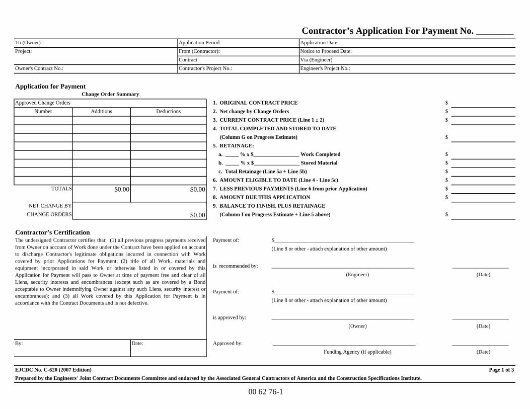
$Number Additions $
$
$
$$$$
$0.00 $$
NET CHANGE BY CHANGE ORDERS $
Payment of:
is recommended by: _____________________(Date)
Payment of:
is approved by: _____________________(Date)
By: Date: Approved by: _____________________(Date)
EJCDC No. C-620 (2007 Edition) Page 1 of 3
9. BALANCE TO FINISH, PLUS RETAINAGE
$0.00 (Column I on Progress Estimate + Line 5 above)
(Owner)
Contractor’s Certification
_____________________________________________________
6. AMOUNT ELIGIBLE TO DATE (Line 4 - Line 5c) TOTALS $0.00 7. LESS PREVIOUS PAYMENTS (Line 6 from prior Application)
8. AMOUNT DUE THIS APPLICATION
a. _____ % x $_________________ Work Completed b. _____ % x $_________________ Stored Material c. Total Retainage (Line 5a + Line 5b)
4. TOTAL COMPLETED AND STORED TO DATE (Column G on Progress Estimate)5. RETAINAGE:
Approved Change Orders 1. ORIGINAL CONTRACT PRICE Deductions 2. Net change by Change Orders
3. CURRENT CONTRACT PRICE (Line 1 ± 2)
Owner's Contract No.: Contractor's Project No.: Engineer's Project No.:
Application for PaymentChange Order Summary
From (Contractor):Via (Engineer)Contract:
Project: Notice to Proceed Date:
Contractor’s Application For Payment No. ________Application Period: Application Date:To (Owner):
Funding Agency (if applicable) _____________________________________________________
Prepared by the Engineers' Joint Contract Documents Committee and endorsed by the Associated General Contractors of America and the Construction Specifications Institute.
$____________________________________________________(Line 8 or other - attach explanation of other amount)
_____________________________________________________(Engineer)
$____________________________________________________(Line 8 or other - attach explanation of other amount)
The undersigned Contractor certifies that: (1) all previous progress payments receivedfrom Owner on account of Work done under the Contract have been applied on accountto discharge Contractor's legitimate obligations incurred in connection with Workcovered by prior Applications for Payment; (2) title of all Work, materials andequipment incorporated in said Work or otherwise listed in or covered by thisApplication for Payment will pass to Owner at time of payment free and clear of allLiens, security interests and encumbrances (except such as are covered by a Bondacceptable to Owner indemnifying Owner against any such Liens, security interest orencumbrances); and (3) all Work covered by this Application for Payment is inaccordance with the Contract Documents and is not defective.
00 62 76-1

Progress Estimate Contractor’s ApplicationFor (contract): Application Number:Application Period: Application Date:
A B C D E F G H IItem Bid Unit Bid
Description Quantity Price Value From Previous Quantity this Value this $ %Application Period Application (not in C or D) (C + E + F) (G / B) (B - G)
Totals
EJCDC No. C-620 (2007 Edition) Page 2 of 3Prepared by the Engineers' Joint Contract Documents Committee and endorsed by the Associated General Contractors of America and the Construction Specifications Institute.
Bid Item No.
Balance to Finish
Materials Presently Stored
Work Completed Total Completed and Stored to Date
00 62 76-2
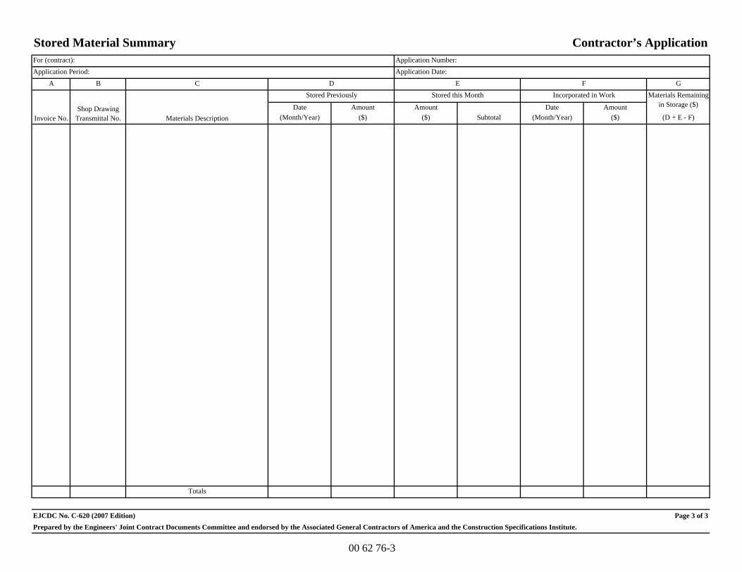
Stored Material Summary Contractor’s ApplicationFor (contract): Application Number:Application Period: Application Date:
A B C D E F GStored this Month
Date Amount Amount Date Amount(Month/Year) ($) ($) Subtotal (Month/Year) ($) (D + E - F)
Totals
EJCDC No. C-620 (2007 Edition) Page 3 of 3
Materials Remaining in Storage ($)
Prepared by the Engineers' Joint Contract Documents Committee and endorsed by the Associated General Contractors of America and the Construction Specifications Institute.
Invoice No.Shop Drawing
Transmittal No. Materials Description
Incorporated in WorkStored Previously
00 62 76-3

THIS PAGE INTENTIONALLY LEFT BLANK

EJCDC C-942 Field Order (2007 Edition) 00 63 36-1 Prepared by the Engineers Joint Contract Documents Committee and endorsed by the Construction Specifications Institute.
Field Order No. Date of Issuance: Effective Date: Project:
Owner:
Owner's Contract No.:
Contract:
Date of Contract:
Contractor:
Engineer's Project No.:
Attention: You are hereby directed to promptly execute this Field Order issued in accordance with General Conditions Paragraph 9.04.A, for minor changes in the Work without changes in Contract Price or Contract Times. If you consider that a change in Contract Price or Contract Times is required, please notify the Engineer immediately and before proceeding with this Work.
Reference:
(Specification Section(s)) (Drawing(s) / Detail(s))
Description:
Attachments:
Engineer:
Receipt Acknowledged by Contractor: Date:
Copy to Owner

THIS PAGE INTENTIONALLY LEFT BLANK

EJCDC C-940 Work Change Directive (2007 Edition) 00 63 49-1 Prepared by the Engineers Joint Contract Documents Committee and endorsed by the Construction Specifications Institute.
Work Change Directive No.
Date of Issuance: Effective Date: Project:
Owner:
Owner's Contract No.:
Contract:
Date of Contract:
Contractor:
Engineer's Project No.:
Contractor is directed to proceed promptly with the following change(s):
Item No. Description
Attachments (list documents supporting change):
Purpose for Work Change Directive: Authorization for Work described herein to proceed on the basis of Cost of the Work due to:
Nonagreement on pricing of proposed change.
Necessity to expedite Work described herein prior to agreeing to changes on Contract Price and Contract Time.
Estimated change in Contract Price and Contract Times:
Contract Price $ (increase/decrease) Contract Time (increase/decrease)
days Recommended for Approval by Engineer: Date
Authorized for Owner by: Date
Received for Contractor by: Date
Received by Funding Agency (if applicable): Date:

THIS PAGE INTENTIONALLY LEFT BLANK

EJCDC C-941 Change Order (2007 Edition) 00 63 63-1 Prepared by the Engineers Joint Contract Documents Committee and endorsed by the Construction Specifications Institute.
Change Order No. ___________
Date of Issuance: Effective Date: Project:
Owner:
Owner's Contract No.:
Contract:
Date of Contract:
Contractor:
Engineer's Project No.:
The Contract Documents are modified as follows upon execution of this Change Order: Description:
Attachments (list documents supporting change):
CHANGE IN CONTRACT PRICE: CHANGE IN CONTRACT TIMES:
Original Contract Price: Original Contract Times: Working days Calendar days
Substantial completion (days or date):
$ Ready for final payment (days or date):
[Increase] [Decrease] from previously approved Change Orders No. ________ to No.: ________ [Increase] [Decrease] from previously approved Change Orders
No. ________to No. ________:
Substantial completion (days):
$ Ready for final payment (days):
Contract Price prior to this Change Order: Contract Times prior to this Change Order:
Substantial completion (days or date):
$ Ready for final payment (days or date):
[Increase] [Decrease] of this Change Order: [Increase] [Decrease] of this Change Order:
Substantial completion (days or date):
$ Ready for final payment (days or date):
Contract Price incorporating this Change Order: Contract Times with all approved Change Orders:
Substantial completion (days or date):
$ Ready for final payment (days or date): RECOMMENDED: ACCEPTED: ACCEPTED:
By: By: By: Engineer (Authorized Signature) Owner (Authorized Signature) Contractor (Authorized Signature)
Date: Date: Date: Approved by Funding Agency (if applicable):
____________________________________________________________
Date:

EJCDC C-941 Change Order (2007 Edition) 00 63 63-2 Prepared by the Engineers Joint Contract Documents Committee and endorsed by the Construction Specifications Institute.
Change Order
Instructions
A. GENERAL INFORMATION
This document was developed to provide a uniform format for handling contract changes that affect Contract Price or Contract Times. Changes that have been initiated by a Work Change Directive must be incorporated into a subsequent Change Order if they affect Price or Times.
Changes that affect Contract Price or Contract Times should be promptly covered by a Change Order. The practice of accumulating Change Orders to reduce the administrative burden may lead to unnecessary disputes.
If Milestones have been listed in the Agreement, any effect of a Change Order thereon should be addressed.
For supplemental instructions and minor changes not involving a change in the Contract Price or Contract Times, a Field Order should be used.
B. COMPLETING THE CHANGE ORDER FORM
Engineer normally initiates the form, including a description of the changes involved and attachments based upon documents and proposals submitted by Contractor, or requests from Owner, or both.
Once Engineer has completed and signed the form, all copies should be sent to Owner or Contractor for approval, depending on whether the Change Order is a true order to the Contractor or the formalization of a negotiated agreement for a previously performed change. After approval by one contracting party, all copies should be sent to the other party for approval. Engineer should make distribution of executed copies after approval by both parties.
If a change only applies to price or to times, cross out the part of the tabulation that does not apply.

EJCDC C-625 (2007 Edition) 00 65 16-1 Prepared by the Engineers Joint Contract Documents Committee and endorsed by the Construction Specifications Institute.
Certificate of Substantial Completion Project: Owner:
Owner's Contract No.:
Contract:
Engineer's Project No.:
This [tentative] [definitive] Certificate of Substantial Completion applies to:
All Work under the Contract Documents: The following specified portions of the Work:
Date of Substantial Completion
The Work to which this Certificate applies has been inspected by authorized representatives of Owner, Contractor, and Engineer, and found to be substantially complete. The Date of Substantial Completion of the Project or portion thereof designated above is hereby declared and is also the date of commencement of applicable warranties required by the Contract Documents, except as stated below. A [tentative] [definitive] list of items to be completed or corrected is attached hereto. This list may not be all-inclusive, and the failure to include any items on such list does not alter the responsibility of the Contractor to complete all Work in accordance with the Contract Documents. The responsibilities between Owner and Contractor for security, operation, safety, maintenance, heat, utilities, insurance and warranties shall be as provided in the Contract Documents except as amended as follows:
Amended Responsibilities Not Amended
Owner's Amended Responsibilities:
Contractor's Amended Responsibilities:
The following documents are attached to and made part of this Certificate:
This Certificate does not constitute an acceptance of Work not in accordance with the Contract Documents nor is it a release of Contractor's obligation to complete the Work in accordance with the Contract Documents.
Executed by Engineer Date
Accepted by Contractor Date
Accepted by Owner Date

THIS PAGE INTENTIONALLY LEFT BLANK

EJCDC C-700 Standard General Conditions of the Construction Contract Copyright © 2007 National Society of Professional Engineers for EJCDC. All rights reserved.
00 72 00 - 1
This document has important legal consequences; consultation with an attorney is encouraged with respect to its use or modification. This document should be adapted to the particular circumstances of the contemplated Project and the controlling Laws and Regulations.
STANDARD GENERAL CONDITIONS OF THE CONSTRUCTION CONTRACT
Prepared by
ENGINEERS JOINT CONTRACT DOCUMENTS COMMITTEE
and
Issued and Published Jointly by
AMERICAN COUNCIL OF ENGINEERING COMPANIES ______________________
ASSOCIATED GENERAL CONTRACTORS OF AMERICA
______________________
AMERICAN SOCIETY OF CIVIL ENGINEERS _______________________
PROFESSIONAL ENGINEERS IN PRIVATE PRACTICE
A Practice Division of the NATIONAL SOCIETY OF PROFESSIONAL ENGINEERS
Endorsed by
CONSTRUCTION SPECIFICATIONS INSTITUTE

EJCDC C-700 Standard General Conditions of the Construction Contract Copyright © 2007 National Society of Professional Engineers for EJCDC. All rights reserved.
00 72 00 - 2
These General Conditions have been prepared for use with the Suggested Forms of Agreement Between Owner and Contractor (EJCDC C-520 or C-525, 2007 Editions). Their provisions are interrelated and a change in one may necessitate a change in the other. Comments concerning their usage are contained in the Narrative Guide to the EJCDC Construction Documents (EJCDC C-001, 2007 Edition). For guidance in the preparation of Supplementary Conditions, see Guide to the Preparation of Supplementary Conditions (EJCDC C-800, 2007 Edition).
Copyright © 2007 National Society of Professional Engineers
1420 King Street, Alexandria, VA 22314-2794 (703) 684-2882 www.nspe.org
American Council of Engineering Companies
1015 15th Street N.W., Washington, DC 20005 (202) 347-7474 www.acec.org
American Society of Civil Engineers
1801 Alexander Bell Drive, Reston, VA 20191-4400 (800) 548-2723 www.asce.org
Associated General Contractors of America
2300 Wilson Boulevard, Suite 400, Arlington, VA 22201-3308 (703) 548-3118 www.agc.org
The copyright for this EJCDC document is owned jointly by the four EJCDC sponsoring organizations and held in trust for their benefit by NSPE.

EJCDC C-700 Standard General Conditions of the Construction Contract Copyright © 2007 National Society of Professional Engineers for EJCDC. All rights reserved.
00 72 00 - 3
STANDARD GENERAL CONDITIONS OF THE CONSTRUCTION CONTRACT
TABLE OF CONTENTS
Page
Article 1 – Definitions and Terminology .......................................................................................................... 7 1.01 Defined Terms ............................................................................................................................... 7 1.02 Terminology ................................................................................................................................ 11
Article 2 – Preliminary Matters ....................................................................................................................... 12 2.01 Delivery of Bonds and Evidence of Insurance ........................................................................... 12 2.02 Copies of Documents .................................................................................................................. 12 2.03 Commencement of Contract Times; Notice to Proceed ............................................................. 12 2.04 Starting the Work ........................................................................................................................ 13 2.05 Before Starting Construction ...................................................................................................... 13 2.06 Preconstruction Conference; Designation of Authorized Representatives ................................ 13 2.07 Initial Acceptance of Schedules .................................................................................................. 13
Article 3 – Contract Documents: Intent, Amending, Reuse .......................................................................... 14 3.01 Intent ............................................................................................................................................ 14 3.02 Reference Standards .................................................................................................................... 14 3.03 Reporting and Resolving Discrepancies ..................................................................................... 15 3.04 Amending and Supplementing Contract Documents ................................................................. 15 3.05 Reuse of Documents ................................................................................................................... 16 3.06 Electronic Data ............................................................................................................................ 16
Article 4 – Availability of Lands; Subsurface and Physical Conditions; Hazardous Environmental Conditions; Reference Points ........................................................................................................... 17
4.01 Availability of Lands ................................................................................................................... 17 4.02 Subsurface and Physical Conditions ........................................................................................... 17 4.03 Differing Subsurface or Physical Conditions ............................................................................. 18 4.04 Underground Facilities ................................................................................................................ 19 4.05 Reference Points .......................................................................................................................... 20 4.06 Hazardous Environmental Condition at Site .............................................................................. 20
Article 5 – Bonds and Insurance ...................................................................................................................... 22 5.01 Performance, Payment, and Other Bonds ................................................................................... 22 5.02 Licensed Sureties and Insurers .................................................................................................... 22 5.03 Certificates of Insurance ............................................................................................................. 23 5.04 Contractor’s Insurance ................................................................................................................ 23 5.05 Owner’s Liability Insurance ........................................................................................................ 25 5.06 Property Insurance ....................................................................................................................... 25 5.07 Waiver of Rights ......................................................................................................................... 26 5.08 Receipt and Application of Insurance Proceeds ......................................................................... 27

EJCDC C-700 Standard General Conditions of the Construction Contract Copyright © 2007 National Society of Professional Engineers for EJCDC. All rights reserved.
00 72 00 - 4
5.09 Acceptance of Bonds and Insurance; Option to Replace ........................................................... 27 5.10 Partial Utilization, Acknowledgment of Property Insurer .......................................................... 28
Article 6 – Contractor’s Responsibilities ........................................................................................................ 28 6.01 Supervision and Superintendence ............................................................................................... 28 6.02 Labor; Working Hours ................................................................................................................ 28 6.03 Services, Materials, and Equipment ........................................................................................... 28 6.04 Progress Schedule ....................................................................................................................... 29 6.05 Substitutes and “Or-Equals” ....................................................................................................... 29 6.06 Concerning Subcontractors, Suppliers, and Others .................................................................... 31 6.07 Patent Fees and Royalties ........................................................................................................... 33 6.08 Permits ......................................................................................................................................... 33 6.09 Laws and Regulations ................................................................................................................. 34 6.10 Taxes ........................................................................................................................................... 34 6.11 Use of Site and Other Areas ........................................................................................................ 34 6.12 Record Documents ...................................................................................................................... 35 6.13 Safety and Protection .................................................................................................................. 35 6.14 Safety Representative .................................................................................................................. 36 6.15 Hazard Communication Programs.............................................................................................. 36 6.16 Emergencies ................................................................................................................................ 36 6.17 Shop Drawings and Samples ...................................................................................................... 37 6.18 Continuing the Work ................................................................................................................... 38 6.19 Contractor’s General Warranty and Guarantee .......................................................................... 39 6.20 Indemnification ........................................................................................................................... 39 6.21 Delegation of Professional Design Services ............................................................................... 40
Article 7 – Other Work at the Site ................................................................................................................... 41 7.01 Related Work at Site ................................................................................................................... 41 7.02 Coordination ................................................................................................................................ 41 7.03 Legal Relationships ..................................................................................................................... 42
Article 8 – Owner’s Responsibilities ............................................................................................................... 42 8.01 Communications to Contractor ................................................................................................... 42 8.02 Replacement of Engineer ............................................................................................................ 42 8.03 Furnish Data ................................................................................................................................ 42 8.04 Pay When Due ............................................................................................................................. 42 8.05 Lands and Easements; Reports and Tests ................................................................................... 42 8.06 Insurance...................................................................................................................................... 42 8.07 Change Orders ............................................................................................................................. 43 8.08 Inspections, Tests, and Approvals .............................................................................................. 43 8.09 Limitations on Owner’s Responsibilities ................................................................................... 43 8.10 Undisclosed Hazardous Environmental Condition .................................................................... 43 8.11 Evidence of Financial Arrangements .......................................................................................... 43 8.12 Compliance with Safety Program ............................................................................................... 43
Article 9 – Engineer’s Status During Construction ......................................................................................... 43 9.01 Owner’s Representative .............................................................................................................. 43

EJCDC C-700 Standard General Conditions of the Construction Contract Copyright © 2007 National Society of Professional Engineers for EJCDC. All rights reserved.
00 72 00 - 5
9.02 Visits to Site ................................................................................................................................ 43 9.03 Project Representative ................................................................................................................. 44 9.04 Authorized Variations in Work .................................................................................................. 44 9.05 Rejecting Defective Work ........................................................................................................... 44 9.06 Shop Drawings, Change Orders and Payments .......................................................................... 45 9.07 Determinations for Unit Price Work .......................................................................................... 45 9.08 Decisions on Requirements of Contract Documents and Acceptability of Work ..................... 45 9.09 Limitations on Engineer’s Authority and Responsibilities ........................................................ 45 9.10 Compliance with Safety Program ............................................................................................... 46
Article 10 – Changes in the Work; Claims ..................................................................................................... 46 10.01 Authorized Changes in the Work ............................................................................................... 46 10.02 Unauthorized Changes in the Work ............................................................................................ 47 10.03 Execution of Change Orders ....................................................................................................... 47 10.04 Notification to Surety .................................................................................................................. 47 10.05 Claims .......................................................................................................................................... 47
Article 11 – Cost of the Work; Allowances; Unit Price Work ....................................................................... 48 11.01 Cost of the Work ......................................................................................................................... 48 11.02 Allowances .................................................................................................................................. 51 11.03 Unit Price Work .......................................................................................................................... 51
Article 12 – Change of Contract Price; Change of Contract Times ............................................................... 52 12.01 Change of Contract Price ............................................................................................................ 52 12.02 Change of Contract Times .......................................................................................................... 53 12.03 Delays .......................................................................................................................................... 53
Article 13 – Tests and Inspections; Correction, Removal or Acceptance of Defective Work ....................... 54 13.01 Notice of Defects ......................................................................................................................... 54 13.02 Access to Work ........................................................................................................................... 54 13.03 Tests and Inspections .................................................................................................................. 55 13.04 Uncovering Work ........................................................................................................................ 55 13.05 Owner May Stop the Work ......................................................................................................... 56 13.06 Correction or Removal of Defective Work ................................................................................ 56 13.07 Correction Period ........................................................................................................................ 56 13.08 Acceptance of Defective Work ................................................................................................... 57 13.09 Owner May Correct Defective Work ......................................................................................... 58
Article 14 – Payments to Contractor and Completion .................................................................................... 58 14.01 Schedule of Values ...................................................................................................................... 58 14.02 Progress Payments ...................................................................................................................... 58 14.03 Contractor’s Warranty of Title .................................................................................................... 61 14.04 Substantial Completion ............................................................................................................... 61 14.05 Partial Utilization ........................................................................................................................ 62 14.06 Final Inspection ........................................................................................................................... 63 14.07 Final Payment .............................................................................................................................. 63 14.08 Final Completion Delayed .......................................................................................................... 64

EJCDC C-700 Standard General Conditions of the Construction Contract Copyright © 2007 National Society of Professional Engineers for EJCDC. All rights reserved.
00 72 00 - 6
14.09 Waiver of Claims ........................................................................................................................ 64
Article 15 – Suspension of Work and Termination ........................................................................................ 65 15.01 Owner May Suspend Work ......................................................................................................... 65 15.02 Owner May Terminate for Cause ............................................................................................... 65 15.03 Owner May Terminate For Convenience ................................................................................... 66 15.04 Contractor May Stop Work or Terminate................................................................................... 66
Article 16 – Dispute Resolution ...................................................................................................................... 67 16.01 Methods and Procedures ............................................................................................................. 67
Article 17 – Miscellaneous .............................................................................................................................. 67 17.01 Giving Notice .............................................................................................................................. 67 17.02 Computation of Times ................................................................................................................ 68 17.03 Cumulative Remedies ................................................................................................................. 68 17.04 Survival of Obligations ............................................................................................................... 68 17.05 Controlling Law .......................................................................................................................... 68 17.06 Headings ...................................................................................................................................... 68
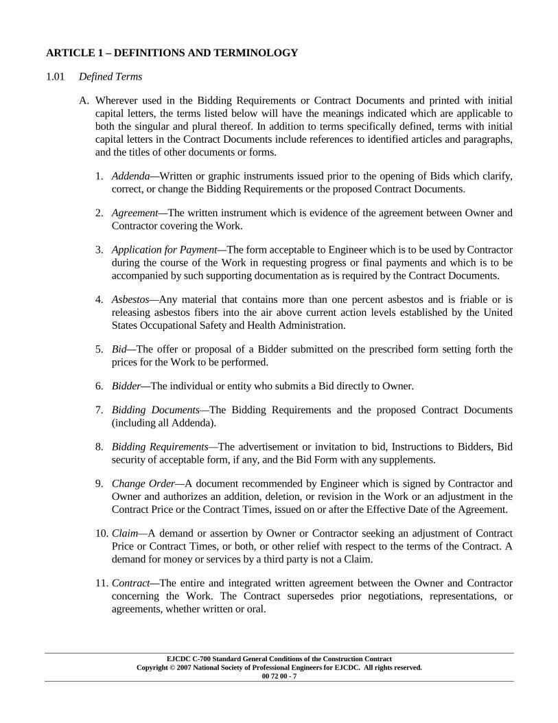
EJCDC C-700 Standard General Conditions of the Construction Contract Copyright © 2007 National Society of Professional Engineers for EJCDC. All rights reserved.
00 72 00 - 7
ARTICLE 1 – DEFINITIONS AND TERMINOLOGY
1.01 Defined Terms
A. Wherever used in the Bidding Requirements or Contract Documents and printed with initial capital letters, the terms listed below will have the meanings indicated which are applicable to both the singular and plural thereof. In addition to terms specifically defined, terms with initial capital letters in the Contract Documents include references to identified articles and paragraphs, and the titles of other documents or forms.
1. Addenda—Written or graphic instruments issued prior to the opening of Bids which clarify, correct, or change the Bidding Requirements or the proposed Contract Documents.
2. Agreement—The written instrument which is evidence of the agreement between Owner and Contractor covering the Work.
3. Application for Payment—The form acceptable to Engineer which is to be used by Contractor during the course of the Work in requesting progress or final payments and which is to be accompanied by such supporting documentation as is required by the Contract Documents.
4. Asbestos—Any material that contains more than one percent asbestos and is friable or is releasing asbestos fibers into the air above current action levels established by the United States Occupational Safety and Health Administration.
5. Bid—The offer or proposal of a Bidder submitted on the prescribed form setting forth the prices for the Work to be performed.
6. Bidder—The individual or entity who submits a Bid directly to Owner.
7. Bidding Documents—The Bidding Requirements and the proposed Contract Documents (including all Addenda).
8. Bidding Requirements—The advertisement or invitation to bid, Instructions to Bidders, Bid security of acceptable form, if any, and the Bid Form with any supplements.
9. Change Order—A document recommended by Engineer which is signed by Contractor and Owner and authorizes an addition, deletion, or revision in the Work or an adjustment in the Contract Price or the Contract Times, issued on or after the Effective Date of the Agreement.
10. Claim—A demand or assertion by Owner or Contractor seeking an adjustment of Contract Price or Contract Times, or both, or other relief with respect to the terms of the Contract. A demand for money or services by a third party is not a Claim.
11. Contract—The entire and integrated written agreement between the Owner and Contractor concerning the Work. The Contract supersedes prior negotiations, representations, or agreements, whether written or oral.

EJCDC C-700 Standard General Conditions of the Construction Contract Copyright © 2007 National Society of Professional Engineers for EJCDC. All rights reserved.
00 72 00 - 8
12. Contract Documents—Those items so designated in the Agreement. Only printed or hard copies of the items listed in the Agreement are Contract Documents. Approved Shop Drawings, other Contractor submittals, and the reports and drawings of subsurface and physical conditions are not Contract Documents.
13. Contract Price—The moneys payable by Owner to Contractor for completion of the Work in accordance with the Contract Documents as stated in the Agreement (subject to the provisions of Paragraph 11.03 in the case of Unit Price Work).
14. Contract Times—The number of days or the dates stated in the Agreement to: (i) achieve Milestones, if any; (ii) achieve Substantial Completion; and (iii) complete the Work so that it is ready for final payment as evidenced by Engineer’s written recommendation of final payment.
15. Contractor—The individual or entity with whom Owner has entered into the Agreement.
16. Cost of the Work—See Paragraph 11.01 for definition.
17. Drawings—That part of the Contract Documents prepared or approved by Engineer which graphically shows the scope, extent, and character of the Work to be performed by Contractor. Shop Drawings and other Contractor submittals are not Drawings as so defined.
18. Effective Date of the Agreement—The date indicated in the Agreement on which it becomes effective, but if no such date is indicated, it means the date on which the Agreement is signed and delivered by the last of the two parties to sign and deliver.
19. Engineer—The individual or entity named as such in the Agreement.
20. Field Order—A written order issued by Engineer which requires minor changes in the Work but which does not involve a change in the Contract Price or the Contract Times.
21. General Requirements—Sections of Division 1 of the Specifications.
22. Hazardous Environmental Condition—The presence at the Site of Asbestos, PCBs, Petroleum, Hazardous Waste, or Radioactive Material in such quantities or circumstances that may present a substantial danger to persons or property exposed thereto.
23. Hazardous Waste—The term Hazardous Waste shall have the meaning provided in Section 1004 of the Solid Waste Disposal Act (42 USC Section 6903) as amended from time to time.
24. Laws and Regulations; Laws or Regulations—Any and all applicable laws, rules, regulations, ordinances, codes, and orders of any and all governmental bodies, agencies, authorities, and courts having jurisdiction.
25. Liens—Charges, security interests, or encumbrances upon Project funds, real property, or personal property.
26. Milestone—A principal event specified in the Contract Documents relating to an intermediate completion date or time prior to Substantial Completion of all the Work.

EJCDC C-700 Standard General Conditions of the Construction Contract Copyright © 2007 National Society of Professional Engineers for EJCDC. All rights reserved.
00 72 00 - 9
27. Notice of Award—The written notice by Owner to the Successful Bidder stating that upon timely compliance by the Successful Bidder with the conditions precedent listed therein, Owner will sign and deliver the Agreement.
28. Notice to Proceed—A written notice given by Owner to Contractor fixing the date on which the Contract Times will commence to run and on which Contractor shall start to perform the Work under the Contract Documents.
29. Owner—The individual or entity with whom Contractor has entered into the Agreement and for whom the Work is to be performed.
30. PCBs—Polychlorinated biphenyls.
31. Petroleum—Petroleum, including crude oil or any fraction thereof which is liquid at standard conditions of temperature and pressure (60 degrees Fahrenheit and 14.7 pounds per square inch absolute), such as oil, petroleum, fuel oil, oil sludge, oil refuse, gasoline, kerosene, and oil mixed with other non-Hazardous Waste and crude oils.
32. Progress Schedule—A schedule, prepared and maintained by Contractor, describing the sequence and duration of the activities comprising the Contractor’s plan to accomplish the Work within the Contract Times.
33. Project—The total construction of which the Work to be performed under the Contract Documents may be the whole, or a part.
34. Project Manual—The bound documentary information prepared for bidding and constructing the Work. A listing of the contents of the Project Manual, which may be bound in one or more volumes, is contained in the table(s) of contents.
35. Radioactive Material—Source, special nuclear, or byproduct material as defined by the Atomic Energy Act of 1954 (42 USC Section 2011 et seq.) as amended from time to time.
36. Resident Project Representative—The authorized representative of Engineer who may be assigned to the Site or any part thereof.
37. Samples—Physical examples of materials, equipment, or workmanship that are representative of some portion of the Work and which establish the standards by which such portion of the Work will be judged.
38. Schedule of Submittals—A schedule, prepared and maintained by Contractor, of required submittals and the time requirements to support scheduled performance of related construction activities.
39. Schedule of Values—A schedule, prepared and maintained by Contractor, allocating portions of the Contract Price to various portions of the Work and used as the basis for reviewing Contractor’s Applications for Payment.

EJCDC C-700 Standard General Conditions of the Construction Contract Copyright © 2007 National Society of Professional Engineers for EJCDC. All rights reserved.
00 72 00 - 10
40. Shop Drawings—All drawings, diagrams, illustrations, schedules, and other data or information which are specifically prepared or assembled by or for Contractor and submitted by Contractor to illustrate some portion of the Work.
41. Site—Lands or areas indicated in the Contract Documents as being furnished by Owner upon which the Work is to be performed, including rights-of-way and easements for access thereto, and such other lands furnished by Owner which are designated for the use of Contractor.
42. Specifications—That part of the Contract Documents consisting of written requirements for materials, equipment, systems, standards and workmanship as applied to the Work, and certain administrative requirements and procedural matters applicable thereto.
43. Subcontractor—An individual or entity having a direct contract with Contractor or with any other Subcontractor for the performance of a part of the Work at the Site.
44. Substantial Completion—The time at which the Work (or a specified part thereof) has progressed to the point where, in the opinion of Engineer, the Work (or a specified part thereof) is sufficiently complete, in accordance with the Contract Documents, so that the Work (or a specified part thereof) can be utilized for the purposes for which it is intended. The terms “substantially complete” and “substantially completed” as applied to all or part of the Work refer to Substantial Completion thereof.
45. Successful Bidder—The Bidder submitting a responsive Bid to whom Owner makes an award.
46. Supplementary Conditions—That part of the Contract Documents which amends or supplements these General Conditions.
47. Supplier—A manufacturer, fabricator, supplier, distributor, materialman, or vendor having a direct contract with Contractor or with any Subcontractor to furnish materials or equipment to be incorporated in the Work by Contractor or Subcontractor.
48. Underground Facilities—All underground pipelines, conduits, ducts, cables, wires, manholes, vaults, tanks, tunnels, or other such facilities or attachments, and any encasements containing such facilities, including those that convey electricity, gases, steam, liquid petroleum products, telephone or other communications, cable television, water, wastewater, storm water, other liquids or chemicals, or traffic or other control systems.
49. Unit Price Work—Work to be paid for on the basis of unit prices.
50. Work—The entire construction or the various separately identifiable parts thereof required to be provided under the Contract Documents. Work includes and is the result of performing or providing all labor, services, and documentation necessary to produce such construction, and furnishing, installing, and incorporating all materials and equipment into such construction, all as required by the Contract Documents.
51. Work Change Directive—A written statement to Contractor issued on or after the Effective Date of the Agreement and signed by Owner and recommended by Engineer ordering an

EJCDC C-700 Standard General Conditions of the Construction Contract Copyright © 2007 National Society of Professional Engineers for EJCDC. All rights reserved.
00 72 00 - 11
addition, deletion, or revision in the Work, or responding to differing or unforeseen subsurface or physical conditions under which the Work is to be performed or to emergencies. A Work Change Directive will not change the Contract Price or the Contract Times but is evidence that the parties expect that the change ordered or documented by a Work Change Directive will be incorporated in a subsequently issued Change Order following negotiations by the parties as to its effect, if any, on the Contract Price or Contract Times.
1.02 Terminology
A. The words and terms discussed in Paragraph 1.02.B through F are not defined but, when used in the Bidding Requirements or Contract Documents, have the indicated meaning.
B. Intent of Certain Terms or Adjectives:
1. The Contract Documents include the terms “as allowed,” “as approved,” “as ordered,” “as directed” or terms of like effect or import to authorize an exercise of professional judgment by Engineer. In addition, the adjectives “reasonable,” “suitable,” “acceptable,” “proper,” “satisfactory,” or adjectives of like effect or import are used to describe an action or determination of Engineer as to the Work. It is intended that such exercise of professional judgment, action, or determination will be solely to evaluate, in general, the Work for compliance with the information in the Contract Documents and with the design concept of the Project as a functioning whole as shown or indicated in the Contract Documents (unless there is a specific statement indicating otherwise). The use of any such term or adjective is not intended to and shall not be effective to assign to Engineer any duty or authority to supervise or direct the performance of the Work, or any duty or authority to undertake responsibility contrary to the provisions of Paragraph 9.09 or any other provision of the Contract Documents.
C. Day:
1. The word “day” means a calendar day of 24 hours measured from midnight to the next midnight.
D. Defective:
1. The word “defective,” when modifying the word “Work,” refers to Work that is unsatisfactory, faulty, or deficient in that it:
a. does not conform to the Contract Documents; or
b. does not meet the requirements of any applicable inspection, reference standard, test, or approval referred to in the Contract Documents; or
c. has been damaged prior to Engineer’s recommendation of final payment (unless responsibility for the protection thereof has been assumed by Owner at Substantial Completion in accordance with Paragraph 14.04 or 14.05).

EJCDC C-700 Standard General Conditions of the Construction Contract Copyright © 2007 National Society of Professional Engineers for EJCDC. All rights reserved.
00 72 00 - 12
E. Furnish, Install, Perform, Provide:
1. The word “furnish,” when used in connection with services, materials, or equipment, shall mean to supply and deliver said services, materials, or equipment to the Site (or some other specified location) ready for use or installation and in usable or operable condition.
2. The word “install,” when used in connection with services, materials, or equipment, shall mean to put into use or place in final position said services, materials, or equipment complete and ready for intended use.
3. The words “perform” or “provide,” when used in connection with services, materials, or equipment, shall mean to furnish and install said services, materials, or equipment complete and ready for intended use.
4. When “furnish,” “install,” “perform,” or “provide” is not used in connection with services, materials, or equipment in a context clearly requiring an obligation of Contractor, “provide” is implied.
F. Unless stated otherwise in the Contract Documents, words or phrases that have a well-known technical or construction industry or trade meaning are used in the Contract Documents in accordance with such recognized meaning.
ARTICLE 2 – PRELIMINARY MATTERS
2.01 Delivery of Bonds and Evidence of Insurance
A. When Contractor delivers the executed counterparts of the Agreement to Owner, Contractor shall also deliver to Owner such bonds as Contractor may be required to furnish.
B. Evidence of Insurance: Before any Work at the Site is started, Contractor and Owner shall each deliver to the other, with copies to each additional insured identified in the Supplementary Conditions, certificates of insurance (and other evidence of insurance which either of them or any additional insured may reasonably request) which Contractor and Owner respectively are required to purchase and maintain in accordance with Article 5.
2.02 Copies of Documents
A. Owner shall furnish to Contractor up to ten printed or hard copies of the Drawings and Project Manual. Additional copies will be furnished upon request at the cost of reproduction.
2.03 Commencement of Contract Times; Notice to Proceed
A. The Contract Times will commence to run on the thirtieth day after the Effective Date of the Agreement or, if a Notice to Proceed is given, on the day indicated in the Notice to Proceed. A Notice to Proceed may be given at any time within 30 days after the Effective Date of the Agreement. In no event will the Contract Times commence to run later than the sixtieth day after the day of Bid opening or the thirtieth day after the Effective Date of the Agreement, whichever date is earlier.

EJCDC C-700 Standard General Conditions of the Construction Contract Copyright © 2007 National Society of Professional Engineers for EJCDC. All rights reserved.
00 72 00 - 13
2.04 Starting the Work
A. Contractor shall start to perform the Work on the date when the Contract Times commence to run. No Work shall be done at the Site prior to the date on which the Contract Times commence to run.
2.05 Before Starting Construction
A. Preliminary Schedules: Within 10 days after the Effective Date of the Agreement (unless otherwise specified in the General Requirements), Contractor shall submit to Engineer for timely review:
1. a preliminary Progress Schedule indicating the times (numbers of days or dates) for starting and completing the various stages of the Work, including any Milestones specified in the Contract Documents;
2. a preliminary Schedule of Submittals; and
3. a preliminary Schedule of Values for all of the Work which includes quantities and prices of items which when added together equal the Contract Price and subdivides the Work into component parts in sufficient detail to serve as the basis for progress payments during performance of the Work. Such prices will include an appropriate amount of overhead and profit applicable to each item of Work.
2.06 Preconstruction Conference; Designation of Authorized Representatives
A. Before any Work at the Site is started, a conference attended by Owner, Contractor, Engineer, and others as appropriate will be held to establish a working understanding among the parties as to the Work and to discuss the schedules referred to in Paragraph 2.05.A, procedures for handling Shop Drawings and other submittals, processing Applications for Payment, and maintaining required records.
B. At this conference Owner and Contractor each shall designate, in writing, a specific individual to act as its authorized representative with respect to the services and responsibilities under the Contract. Such individuals shall have the authority to transmit instructions, receive information, render decisions relative to the Contract, and otherwise act on behalf of each respective party.
2.07 Initial Acceptance of Schedules
A. At least 10 days before submission of the first Application for Payment a conference attended by Contractor, Engineer, and others as appropriate will be held to review for acceptability to Engineer as provided below the schedules submitted in accordance with Paragraph 2.05.A. Contractor shall have an additional 10 days to make corrections and adjustments and to complete and resubmit the schedules. No progress payment shall be made to Contractor until acceptable schedules are submitted to Engineer.
1. The Progress Schedule will be acceptable to Engineer if it provides an orderly progression of the Work to completion within the Contract Times. Such acceptance will not impose on

EJCDC C-700 Standard General Conditions of the Construction Contract Copyright © 2007 National Society of Professional Engineers for EJCDC. All rights reserved.
00 72 00 - 14
Engineer responsibility for the Progress Schedule, for sequencing, scheduling, or progress of the Work, nor interfere with or relieve Contractor from Contractor’s full responsibility therefor.
2. Contractor’s Schedule of Submittals will be acceptable to Engineer if it provides a workable arrangement for reviewing and processing the required submittals.
3. Contractor’s Schedule of Values will be acceptable to Engineer as to form and substance if it provides a reasonable allocation of the Contract Price to component parts of the Work.
ARTICLE 3 – CONTRACT DOCUMENTS: INTENT, AMENDING, REUSE
3.01 Intent
A. The Contract Documents are complementary; what is required by one is as binding as if required by all.
B. It is the intent of the Contract Documents to describe a functionally complete project (or part thereof) to be constructed in accordance with the Contract Documents. Any labor, documentation, services, materials, or equipment that reasonably may be inferred from the Contract Documents or from prevailing custom or trade usage as being required to produce the indicated result will be provided whether or not specifically called for, at no additional cost to Owner.
C. Clarifications and interpretations of the Contract Documents shall be issued by Engineer as provided in Article 9.
3.02 Reference Standards
A. Standards, Specifications, Codes, Laws, and Regulations
1. Reference to standards, specifications, manuals, or codes of any technical society, organization, or association, or to Laws or Regulations, whether such reference be specific or by implication, shall mean the standard, specification, manual, code, or Laws or Regulations in effect at the time of opening of Bids (or on the Effective Date of the Agreement if there were no Bids), except as may be otherwise specifically stated in the Contract Documents.
2. No provision of any such standard, specification, manual, or code, or any instruction of a Supplier, shall be effective to change the duties or responsibilities of Owner, Contractor, or Engineer, or any of their subcontractors, consultants, agents, or employees, from those set forth in the Contract Documents. No such provision or instruction shall be effective to assign to Owner, Engineer, or any of their officers, directors, members, partners, employees, agents, consultants, or subcontractors, any duty or authority to supervise or direct the performance of the Work or any duty or authority to undertake responsibility inconsistent with the provisions of the Contract Documents.

EJCDC C-700 Standard General Conditions of the Construction Contract Copyright © 2007 National Society of Professional Engineers for EJCDC. All rights reserved.
00 72 00 - 15
3.03 Reporting and Resolving Discrepancies
A. Reporting Discrepancies:
1. Contractor’s Review of Contract Documents Before Starting Work: Before undertaking each part of the Work, Contractor shall carefully study and compare the Contract Documents and check and verify pertinent figures therein and all applicable field measurements. Contractor shall promptly report in writing to Engineer any conflict, error, ambiguity, or discrepancy which Contractor discovers, or has actual knowledge of, and shall obtain a written interpretation or clarification from Engineer before proceeding with any Work affected thereby.
2. Contractor’s Review of Contract Documents During Performance of Work: If, during the performance of the Work, Contractor discovers any conflict, error, ambiguity, or discrepancy within the Contract Documents, or between the Contract Documents and (a) any applicable Law or Regulation , (b) any standard, specification, manual, or code, or (c) any instruction of any Supplier, then Contractor shall promptly report it to Engineer in writing. Contractor shall not proceed with the Work affected thereby (except in an emergency as required by Paragraph 6.16.A) until an amendment or supplement to the Contract Documents has been issued by one of the methods indicated in Paragraph 3.04.
3. Contractor shall not be liable to Owner or Engineer for failure to report any conflict, error, ambiguity, or discrepancy in the Contract Documents unless Contractor had actual knowledge thereof.
B. Resolving Discrepancies:
1. Except as may be otherwise specifically stated in the Contract Documents, the provisions of the Contract Documents shall take precedence in resolving any conflict, error, ambiguity, or discrepancy between the provisions of the Contract Documents and:
a. the provisions of any standard, specification, manual, or code, or the instruction of any Supplier (whether or not specifically incorporated by reference in the Contract Documents); or
b. the provisions of any Laws or Regulations applicable to the performance of the Work (unless such an interpretation of the provisions of the Contract Documents would result in violation of such Law or Regulation).
3.04 Amending and Supplementing Contract Documents
A. The Contract Documents may be amended to provide for additions, deletions, and revisions in the Work or to modify the terms and conditions thereof by either a Change Order or a Work Change Directive.
B. The requirements of the Contract Documents may be supplemented, and minor variations and deviations in the Work may be authorized, by one or more of the following ways:

EJCDC C-700 Standard General Conditions of the Construction Contract Copyright © 2007 National Society of Professional Engineers for EJCDC. All rights reserved.
00 72 00 - 16
1. A Field Order;
2. Engineer’s approval of a Shop Drawing or Sample (subject to the provisions of Paragraph 6.17.D.3); or
3. Engineer’s written interpretation or clarification.
3.05 Reuse of Documents
A. Contractor and any Subcontractor or Supplier shall not:
1. have or acquire any title to or ownership rights in any of the Drawings, Specifications, or other documents (or copies of any thereof) prepared by or bearing the seal of Engineer or its consultants, including electronic media editions; or
2. reuse any such Drawings, Specifications, other documents, or copies thereof on extensions of the Project or any other project without written consent of Owner and Engineer and specific written verification or adaptation by Engineer.
B. The prohibitions of this Paragraph 3.05 will survive final payment, or termination of the Contract. Nothing herein shall preclude Contractor from retaining copies of the Contract Documents for record purposes.
3.06 Electronic Data
A. Unless otherwise stated in the Supplementary Conditions, the data furnished by Owner or Engineer to Contractor, or by Contractor to Owner or Engineer, that may be relied upon are limited to the printed copies (also known as hard copies). Files in electronic media format of text, data, graphics, or other types are furnished only for the convenience of the receiving party. Any conclusion or information obtained or derived from such electronic files will be at the user’s sole risk. If there is a discrepancy between the electronic files and the hard copies, the hard copies govern.
B. Because data stored in electronic media format can deteriorate or be modified inadvertently or otherwise without authorization of the data’s creator, the party receiving electronic files agrees that it will perform acceptance tests or procedures within 60 days, after which the receiving party shall be deemed to have accepted the data thus transferred. Any errors detected within the 60-day acceptance period will be corrected by the transferring party.
C. When transferring documents in electronic media format, the transferring party makes no representations as to long term compatibility, usability, or readability of documents resulting from the use of software application packages, operating systems, or computer hardware differing from those used by the data’s creator.

EJCDC C-700 Standard General Conditions of the Construction Contract Copyright © 2007 National Society of Professional Engineers for EJCDC. All rights reserved.
00 72 00 - 17
ARTICLE 4 – AVAILABILITY OF LANDS; SUBSURFACE AND PHYSICAL CONDITIONS; HAZARDOUS ENVIRONMENTAL CONDITIONS; REFERENCE POINTS
4.01 Availability of Lands
A. Owner shall furnish the Site. Owner shall notify Contractor of any encumbrances or restrictions not of general application but specifically related to use of the Site with which Contractor must comply in performing the Work. Owner will obtain in a timely manner and pay for easements for permanent structures or permanent changes in existing facilities. If Contractor and Owner are unable to agree on entitlement to or on the amount or extent, if any, of any adjustment in the Contract Price or Contract Times, or both, as a result of any delay in Owner’s furnishing the Site or a part thereof, Contractor may make a Claim therefor as provided in Paragraph 10.05.
B. Upon reasonable written request, Owner shall furnish Contractor with a current statement of record legal title and legal description of the lands upon which the Work is to be performed and Owner’s interest therein as necessary for giving notice of or filing a mechanic’s or construction lien against such lands in accordance with applicable Laws and Regulations.
C. Contractor shall provide for all additional lands and access thereto that may be required for temporary construction facilities or storage of materials and equipment.
4.02 Subsurface and Physical Conditions
A. Reports and Drawings: The Supplementary Conditions identify:
1. those reports known to Owner of explorations and tests of subsurface conditions at or contiguous to the Site; and
2. those drawings known to Owner of physical conditions relating to existing surface or subsurface structures at the Site (except Underground Facilities).
B. Limited Reliance by Contractor on Technical Data Authorized: Contractor may rely upon the accuracy of the “technical data” contained in such reports and drawings, but such reports and drawings are not Contract Documents. Such “technical data” is identified in the Supplementary Conditions. Except for such reliance on such “technical data,” Contractor may not rely upon or make any claim against Owner or Engineer, or any of their officers, directors, members, partners, employees, agents, consultants, or subcontractors with respect to:
1. the completeness of such reports and drawings for Contractor’s purposes, including, but not limited to, any aspects of the means, methods, techniques, sequences, and procedures of construction to be employed by Contractor, and safety precautions and programs incident thereto; or
2. other data, interpretations, opinions, and information contained in such reports or shown or indicated in such drawings; or
3. any Contractor interpretation of or conclusion drawn from any “technical data” or any such other data, interpretations, opinions, or information.

EJCDC C-700 Standard General Conditions of the Construction Contract Copyright © 2007 National Society of Professional Engineers for EJCDC. All rights reserved.
00 72 00 - 18
4.03 Differing Subsurface or Physical Conditions
A. Notice: If Contractor believes that any subsurface or physical condition that is uncovered or revealed either:
1. is of such a nature as to establish that any “technical data” on which Contractor is entitled to rely as provided in Paragraph 4.02 is materially inaccurate; or
2. is of such a nature as to require a change in the Contract Documents; or
3. differs materially from that shown or indicated in the Contract Documents; or
4. is of an unusual nature, and differs materially from conditions ordinarily encountered and generally recognized as inherent in work of the character provided for in the Contract Documents;
then Contractor shall, promptly after becoming aware thereof and before further disturbing the subsurface or physical conditions or performing any Work in connection therewith (except in an emergency as required by Paragraph 6.16.A), notify Owner and Engineer in writing about such condition. Contractor shall not further disturb such condition or perform any Work in connection therewith (except as aforesaid) until receipt of written order to do so.
B. Engineer’s Review: After receipt of written notice as required by Paragraph 4.03.A, Engineer will promptly review the pertinent condition, determine the necessity of Owner’s obtaining additional exploration or tests with respect thereto, and advise Owner in writing (with a copy to Contractor) of Engineer’s findings and conclusions.
C. Possible Price and Times Adjustments:
1. The Contract Price or the Contract Times, or both, will be equitably adjusted to the extent that the existence of such differing subsurface or physical condition causes an increase or decrease in Contractor’s cost of, or time required for, performance of the Work; subject, however, to the following:
a. such condition must meet any one or more of the categories described in Paragraph 4.03.A; and
b. with respect to Work that is paid for on a unit price basis, any adjustment in Contract Price will be subject to the provisions of Paragraphs 9.07 and 11.03.
2. Contractor shall not be entitled to any adjustment in the Contract Price or Contract Times if:
a. Contractor knew of the existence of such conditions at the time Contractor made a final commitment to Owner with respect to Contract Price and Contract Times by the submission of a Bid or becoming bound under a negotiated contract; or
b. the existence of such condition could reasonably have been discovered or revealed as a result of any examination, investigation, exploration, test, or study of the Site and

EJCDC C-700 Standard General Conditions of the Construction Contract Copyright © 2007 National Society of Professional Engineers for EJCDC. All rights reserved.
00 72 00 - 19
contiguous areas required by the Bidding Requirements or Contract Documents to be conducted by or for Contractor prior to Contractor’s making such final commitment; or
c. Contractor failed to give the written notice as required by Paragraph 4.03.A.
3. If Owner and Contractor are unable to agree on entitlement to or on the amount or extent, if any, of any adjustment in the Contract Price or Contract Times, or both, a Claim may be made therefor as provided in Paragraph 10.05. However, neither Owner or Engineer, or any of their officers, directors, members, partners, employees, agents, consultants, or subcontractors shall be liable to Contractor for any claims, costs, losses, or damages (including but not limited to all fees and charges of engineers, architects, attorneys, and other professionals and all court or arbitration or other dispute resolution costs) sustained by Contractor on or in connection with any other project or anticipated project.
4.04 Underground Facilities
A. Shown or Indicated: The information and data shown or indicated in the Contract Documents with respect to existing Underground Facilities at or contiguous to the Site is based on information and data furnished to Owner or Engineer by the owners of such Underground Facilities, including Owner, or by others. Unless it is otherwise expressly provided in the Supplementary Conditions:
1. Owner and Engineer shall not be responsible for the accuracy or completeness of any such information or data provided by others; and
2. the cost of all of the following will be included in the Contract Price, and Contractor shall have full responsibility for:
a. reviewing and checking all such information and data;
b. locating all Underground Facilities shown or indicated in the Contract Documents;
c. coordination of the Work with the owners of such Underground Facilities, including Owner, during construction; and
d. the safety and protection of all such Underground Facilities and repairing any damage thereto resulting from the Work.
B. Not Shown or Indicated:
1. If an Underground Facility is uncovered or revealed at or contiguous to the Site which was not shown or indicated, or not shown or indicated with reasonable accuracy in the Contract Documents, Contractor shall, promptly after becoming aware thereof and before further disturbing conditions affected thereby or performing any Work in connection therewith (except in an emergency as required by Paragraph 6.16.A), identify the owner of such Underground Facility and give written notice to that owner and to Owner and Engineer. Engineer will promptly review the Underground Facility and determine the extent, if any, to which a change is required in the Contract Documents to reflect and document the

EJCDC C-700 Standard General Conditions of the Construction Contract Copyright © 2007 National Society of Professional Engineers for EJCDC. All rights reserved.
00 72 00 - 20
consequences of the existence or location of the Underground Facility. During such time, Contractor shall be responsible for the safety and protection of such Underground Facility.
2. If Engineer concludes that a change in the Contract Documents is required, a Work Change Directive or a Change Order will be issued to reflect and document such consequences. An equitable adjustment shall be made in the Contract Price or Contract Times, or both, to the extent that they are attributable to the existence or location of any Underground Facility that was not shown or indicated or not shown or indicated with reasonable accuracy in the Contract Documents and that Contractor did not know of and could not reasonably have been expected to be aware of or to have anticipated. If Owner and Contractor are unable to agree on entitlement to or on the amount or extent, if any, of any such adjustment in Contract Price or Contract Times, Owner or Contractor may make a Claim therefor as provided in Paragraph 10.05.
4.05 Reference Points
A. Owner shall provide engineering surveys to establish reference points for construction which in Engineer’s judgment are necessary to enable Contractor to proceed with the Work. Contractor shall be responsible for laying out the Work, shall protect and preserve the established reference points and property monuments, and shall make no changes or relocations without the prior written approval of Owner. Contractor shall report to Engineer whenever any reference point or property monument is lost or destroyed or requires relocation because of necessary changes in grades or locations, and shall be responsible for the accurate replacement or relocation of such reference points or property monuments by professionally qualified personnel.
4.06 Hazardous Environmental Condition at Site
A. Reports and Drawings: The Supplementary Conditions identify those reports and drawings known to Owner relating to Hazardous Environmental Conditions that have been identified at the Site.
B. Limited Reliance by Contractor on Technical Data Authorized: Contractor may rely upon the accuracy of the “technical data” contained in such reports and drawings, but such reports and drawings are not Contract Documents. Such “technical data” is identified in the Supplementary Conditions. Except for such reliance on such “technical data,” Contractor may not rely upon or make any claim against Owner or Engineer, or any of their officers, directors, members, partners, employees, agents, consultants, or subcontractors with respect to:
1. the completeness of such reports and drawings for Contractor’s purposes, including, but not limited to, any aspects of the means, methods, techniques, sequences and procedures of construction to be employed by Contractor and safety precautions and programs incident thereto; or
2. other data, interpretations, opinions and information contained in such reports or shown or indicated in such drawings; or
3. any Contractor interpretation of or conclusion drawn from any “technical data” or any such other data, interpretations, opinions or information.

EJCDC C-700 Standard General Conditions of the Construction Contract Copyright © 2007 National Society of Professional Engineers for EJCDC. All rights reserved.
00 72 00 - 21
C. Contractor shall not be responsible for any Hazardous Environmental Condition uncovered or revealed at the Site which was not shown or indicated in Drawings or Specifications or identified in the Contract Documents to be within the scope of the Work. Contractor shall be responsible for a Hazardous Environmental Condition created with any materials brought to the Site by Contractor, Subcontractors, Suppliers, or anyone else for whom Contractor is responsible.
D. If Contractor encounters a Hazardous Environmental Condition or if Contractor or anyone for whom Contractor is responsible creates a Hazardous Environmental Condition, Contractor shall immediately: (i) secure or otherwise isolate such condition; (ii) stop all Work in connection with such condition and in any area affected thereby (except in an emergency as required by Paragraph 6.16.A); and (iii) notify Owner and Engineer (and promptly thereafter confirm such notice in writing). Owner shall promptly consult with Engineer concerning the necessity for Owner to retain a qualified expert to evaluate such condition or take corrective action, if any. Promptly after consulting with Engineer, Owner shall take such actions as are necessary to permit Owner to timely obtain required permits and provide Contractor the written notice required by Paragraph 4.06.E.
E. Contractor shall not be required to resume Work in connection with such condition or in any affected area until after Owner has obtained any required permits related thereto and delivered written notice to Contractor: (i) specifying that such condition and any affected area is or has been rendered safe for the resumption of Work; or (ii) specifying any special conditions under which such Work may be resumed safely. If Owner and Contractor cannot agree as to entitlement to or on the amount or extent, if any, of any adjustment in Contract Price or Contract Times, or both, as a result of such Work stoppage or such special conditions under which Work is agreed to be resumed by Contractor, either party may make a Claim therefor as provided in Paragraph 10.05.
F. If after receipt of such written notice Contractor does not agree to resume such Work based on a reasonable belief it is unsafe, or does not agree to resume such Work under such special conditions, then Owner may order the portion of the Work that is in the area affected by such condition to be deleted from the Work. If Owner and Contractor cannot agree as to entitlement to or on the amount or extent, if any, of an adjustment in Contract Price or Contract Times as a result of deleting such portion of the Work, then either party may make a Claim therefor as provided in Paragraph 10.05. Owner may have such deleted portion of the Work performed by Owner’s own forces or others in accordance with Article 7.
G. To the fullest extent permitted by Laws and Regulations, Owner shall indemnify and hold harmless Contractor, Subcontractors, and Engineer, and the officers, directors, members, partners, employees, agents, consultants, and subcontractors of each and any of them from and against all claims, costs, losses, and damages (including but not limited to all fees and charges of engineers, architects, attorneys, and other professionals and all court or arbitration or other dispute resolution costs) arising out of or relating to a Hazardous Environmental Condition, provided that such Hazardous Environmental Condition: (i) was not shown or indicated in the Drawings or Specifications or identified in the Contract Documents to be included within the scope of the Work, and (ii) was not created by Contractor or by anyone for whom Contractor is responsible. Nothing in this Paragraph 4.06.G shall obligate Owner to indemnify any individual or entity from and against the consequences of that individual’s or entity’s own negligence.

EJCDC C-700 Standard General Conditions of the Construction Contract Copyright © 2007 National Society of Professional Engineers for EJCDC. All rights reserved.
00 72 00 - 22
H. To the fullest extent permitted by Laws and Regulations, Contractor shall indemnify and hold harmless Owner and Engineer, and the officers, directors, members, partners, employees, agents, consultants, and subcontractors of each and any of them from and against all claims, costs, losses, and damages (including but not limited to all fees and charges of engineers, architects, attorneys, and other professionals and all court or arbitration or other dispute resolution costs) arising out of or relating to a Hazardous Environmental Condition created by Contractor or by anyone for whom Contractor is responsible. Nothing in this Paragraph 4.06.H shall obligate Contractor to indemnify any individual or entity from and against the consequences of that individual’s or entity’s own negligence.
I. The provisions of Paragraphs 4.02, 4.03, and 4.04 do not apply to a Hazardous Environmental Condition uncovered or revealed at the Site.
ARTICLE 5 – BONDS AND INSURANCE
5.01 Performance, Payment, and Other Bonds
A. Contractor shall furnish performance and payment bonds, each in an amount at least equal to the Contract Price as security for the faithful performance and payment of all of Contractor’s obligations under the Contract Documents. These bonds shall remain in effect until one year after the date when final payment becomes due or until completion of the correction period specified in Paragraph 13.07, whichever is later, except as provided otherwise by Laws or Regulations or by the Contract Documents. Contractor shall also furnish such other bonds as are required by the Contract Documents.
B. All bonds shall be in the form prescribed by the Contract Documents except as provided otherwise by Laws or Regulations, and shall be executed by such sureties as are named in the list of “Companies Holding Certificates of Authority as Acceptable Sureties on Federal Bonds and as Acceptable Reinsuring Companies” as published in Circular 570 (amended) by the Financial Management Service, Surety Bond Branch, U.S. Department of the Treasury. All bonds signed by an agent or attorney-in-fact must be accompanied by a certified copy of that individual’s authority to bind the surety. The evidence of authority shall show that it is effective on the date the agent or attorney-in-fact signed each bond.
C. If the surety on any bond furnished by Contractor is declared bankrupt or becomes insolvent or its right to do business is terminated in any state where any part of the Project is located or it ceases to meet the requirements of Paragraph 5.01.B, Contractor shall promptly notify Owner and Engineer and shall, within 20 days after the event giving rise to such notification, provide another bond and surety, both of which shall comply with the requirements of Paragraphs 5.01.B and 5.02.
5.02 Licensed Sureties and Insurers
A. All bonds and insurance required by the Contract Documents to be purchased and maintained by Owner or Contractor shall be obtained from surety or insurance companies that are duly licensed or authorized in the jurisdiction in which the Project is located to issue bonds or insurance policies for the limits and coverages so required. Such surety and insurance companies shall also

EJCDC C-700 Standard General Conditions of the Construction Contract Copyright © 2007 National Society of Professional Engineers for EJCDC. All rights reserved.
00 72 00 - 23
meet such additional requirements and qualifications as may be provided in the Supplementary Conditions.
5.03 Certificates of Insurance
A. Contractor shall deliver to Owner, with copies to each additional insured and loss payee identified in the Supplementary Conditions, certificates of insurance (and other evidence of insurance requested by Owner or any other additional insured) which Contractor is required to purchase and maintain.
B. Owner shall deliver to Contractor, with copies to each additional insured and loss payee identified in the Supplementary Conditions, certificates of insurance (and other evidence of insurance requested by Contractor or any other additional insured) which Owner is required to purchase and maintain.
C. Failure of Owner to demand such certificates or other evidence of Contractor's full compliance with these insurance requirements or failure of Owner to identify a deficiency in compliance from the evidence provided shall not be construed as a waiver of Contractor’s obligation to maintain such insurance.
D. Owner does not represent that insurance coverage and limits established in this Contract necessarily will be adequate to protect Contractor.
E. The insurance and insurance limits required herein shall not be deemed as a limitation on Contractor’s liability under the indemnities granted to Owner in the Contract Documents.
5.04 Contractor’s Insurance
A. Contractor shall purchase and maintain such insurance as is appropriate for the Work being performed and as will provide protection from claims set forth below which may arise out of or result from Contractor’s performance of the Work and Contractor’s other obligations under the Contract Documents, whether it is to be performed by Contractor, any Subcontractor or Supplier, or by anyone directly or indirectly employed by any of them to perform any of the Work, or by anyone for whose acts any of them may be liable:
1. claims under workers’ compensation, disability benefits, and other similar employee benefit acts;
2. claims for damages because of bodily injury, occupational sickness or disease, or death of Contractor’s employees;
3. claims for damages because of bodily injury, sickness or disease, or death of any person other than Contractor’s employees;
4. claims for damages insured by reasonably available personal injury liability coverage which are sustained:

EJCDC C-700 Standard General Conditions of the Construction Contract Copyright © 2007 National Society of Professional Engineers for EJCDC. All rights reserved.
00 72 00 - 24
a. by any person as a result of an offense directly or indirectly related to the employment of such person by Contractor, or
b. by any other person for any other reason;
5. claims for damages, other than to the Work itself, because of injury to or destruction of tangible property wherever located, including loss of use resulting therefrom; and
6. claims for damages because of bodily injury or death of any person or property damage arising out of the ownership, maintenance or use of any motor vehicle.
B. The policies of insurance required by this Paragraph 5.04 shall:
1. with respect to insurance required by Paragraphs 5.04.A.3 through 5.04.A.6 inclusive, be written on an occurrence basis, include as additional insureds (subject to any customary exclusion regarding professional liability) Owner and Engineer, and any other individuals or entities identified in the Supplementary Conditions, all of whom shall be listed as additional insureds, and include coverage for the respective officers, directors, members, partners, employees, agents, consultants, and subcontractors of each and any of all such additional insureds, and the insurance afforded to these additional insureds shall provide primary coverage for all claims covered thereby;
2. include at least the specific coverages and be written for not less than the limits of liability provided in the Supplementary Conditions or required by Laws or Regulations, whichever is greater;
3. include contractual liability insurance covering Contractor’s indemnity obligations under Paragraphs 6.11 and 6.20;
4. contain a provision or endorsement that the coverage afforded will not be canceled, materially changed or renewal refused until at least 30 days prior written notice has been given to Owner and Contractor and to each other additional insured identified in the Supplementary Conditions to whom a certificate of insurance has been issued (and the certificates of insurance furnished by the Contractor pursuant to Paragraph 5.03 will so provide);
5. remain in effect at least until final payment and at all times thereafter when Contractor may be correcting, removing, or replacing defective Work in accordance with Paragraph 13.07; and
6. include completed operations coverage:
a. Such insurance shall remain in effect for two years after final payment.
b. Contractor shall furnish Owner and each other additional insured identified in the Supplementary Conditions, to whom a certificate of insurance has been issued, evidence satisfactory to Owner and any such additional insured of continuation of such insurance at final payment and one year thereafter.

EJCDC C-700 Standard General Conditions of the Construction Contract Copyright © 2007 National Society of Professional Engineers for EJCDC. All rights reserved.
00 72 00 - 25
5.05 Owner’s Liability Insurance
A. In addition to the insurance required to be provided by Contractor under Paragraph 5.04, Owner, at Owner’s option, may purchase and maintain at Owner’s expense Owner’s own liability insurance as will protect Owner against claims which may arise from operations under the Contract Documents.
5.06 Property Insurance
A. Unless otherwise provided in the Supplementary Conditions, Owner shall purchase and maintain property insurance upon the Work at the Site in the amount of the full replacement cost thereof (subject to such deductible amounts as may be provided in the Supplementary Conditions or required by Laws and Regulations). This insurance shall:
1. include the interests of Owner, Contractor, Subcontractors, and Engineer, and any other individuals or entities identified in the Supplementary Conditions, and the officers, directors, members, partners, employees, agents, consultants, and subcontractors of each and any of them, each of whom is deemed to have an insurable interest and shall be listed as a loss payee;
2. be written on a Builder’s Risk “all-risk” policy form that shall at least include insurance for physical loss or damage to the Work, temporary buildings, falsework, and materials and equipment in transit, and shall insure against at least the following perils or causes of loss: fire, lightning, extended coverage, theft, vandalism and malicious mischief, earthquake, collapse, debris removal, demolition occasioned by enforcement of Laws and Regulations, water damage (other than that caused by flood), and such other perils or causes of loss as may be specifically required by the Supplementary Conditions.
3. include expenses incurred in the repair or replacement of any insured property (including but not limited to fees and charges of engineers and architects);
4. cover materials and equipment stored at the Site or at another location that was agreed to in writing by Owner prior to being incorporated in the Work, provided that such materials and equipment have been included in an Application for Payment recommended by Engineer;
5. allow for partial utilization of the Work by Owner;
6. include testing and startup; and
7. be maintained in effect until final payment is made unless otherwise agreed to in writing by Owner, Contractor, and Engineer with 30 days written notice to each other loss payee to whom a certificate of insurance has been issued.
B. Owner shall purchase and maintain such equipment breakdown insurance or additional property insurance as may be required by the Supplementary Conditions or Laws and Regulations which will include the interests of Owner, Contractor, Subcontractors, and Engineer, and any other individuals or entities identified in the Supplementary Conditions, and the officers, directors,

EJCDC C-700 Standard General Conditions of the Construction Contract Copyright © 2007 National Society of Professional Engineers for EJCDC. All rights reserved.
00 72 00 - 26
members, partners, employees, agents, consultants and subcontractors of each and any of them, each of whom is deemed to have an insurable interest and shall be listed as a loss payee.
C. All the policies of insurance (and the certificates or other evidence thereof) required to be purchased and maintained in accordance with this Paragraph 5.06 will contain a provision or endorsement that the coverage afforded will not be canceled or materially changed or renewal refused until at least 30 days prior written notice has been given to Owner and Contractor and to each other loss payee to whom a certificate of insurance has been issued and will contain waiver provisions in accordance with Paragraph 5.07.
D. Owner shall not be responsible for purchasing and maintaining any property insurance specified in this Paragraph 5.06 to protect the interests of Contractor, Subcontractors, or others in the Work to the extent of any deductible amounts that are identified in the Supplementary Conditions. The risk of loss within such identified deductible amount will be borne by Contractor, Subcontractors, or others suffering any such loss, and if any of them wishes property insurance coverage within the limits of such amounts, each may purchase and maintain it at the purchaser’s own expense.
E. If Contractor requests in writing that other special insurance be included in the property insurance policies provided under this Paragraph 5.06, Owner shall, if possible, include such insurance, and the cost thereof will be charged to Contractor by appropriate Change Order. Prior to commencement of the Work at the Site, Owner shall in writing advise Contractor whether or not such other insurance has been procured by Owner.
5.07 Waiver of Rights
A. Owner and Contractor intend that all policies purchased in accordance with Paragraph 5.06 will protect Owner, Contractor, Subcontractors, and Engineer, and all other individuals or entities identified in the Supplementary Conditions as loss payees (and the officers, directors, members, partners, employees, agents, consultants, and subcontractors of each and any of them) in such policies and will provide primary coverage for all losses and damages caused by the perils or causes of loss covered thereby. All such policies shall contain provisions to the effect that in the event of payment of any loss or damage the insurers will have no rights of recovery against any of the insureds or loss payees thereunder. Owner and Contractor waive all rights against each other and their respective officers, directors, members, partners, employees, agents, consultants and subcontractors of each and any of them for all losses and damages caused by, arising out of or resulting from any of the perils or causes of loss covered by such policies and any other property insurance applicable to the Work; and, in addition, waive all such rights against Subcontractors and Engineer, and all other individuals or entities identified in the Supplementary Conditions as loss payees (and the officers, directors, members, partners, employees, agents, consultants, and subcontractors of each and any of them) under such policies for losses and damages so caused. None of the above waivers shall extend to the rights that any party making such waiver may have to the proceeds of insurance held by Owner as trustee or otherwise payable under any policy so issued.
B. Owner waives all rights against Contractor, Subcontractors, and Engineer, and the officers, directors, members, partners, employees, agents, consultants and subcontractors of each and any of them for:

EJCDC C-700 Standard General Conditions of the Construction Contract Copyright © 2007 National Society of Professional Engineers for EJCDC. All rights reserved.
00 72 00 - 27
1. loss due to business interruption, loss of use, or other consequential loss extending beyond direct physical loss or damage to Owner’s property or the Work caused by, arising out of, or resulting from fire or other perils whether or not insured by Owner; and
2. loss or damage to the completed Project or part thereof caused by, arising out of, or resulting from fire or other insured peril or cause of loss covered by any property insurance maintained on the completed Project or part thereof by Owner during partial utilization pursuant to Paragraph 14.05, after Substantial Completion pursuant to Paragraph 14.04, or after final payment pursuant to Paragraph 14.07.
C. Any insurance policy maintained by Owner covering any loss, damage or consequential loss referred to in Paragraph 5.07.B shall contain provisions to the effect that in the event of payment of any such loss, damage, or consequential loss, the insurers will have no rights of recovery against Contractor, Subcontractors, or Engineer, and the officers, directors, members, partners, employees, agents, consultants and subcontractors of each and any of them.
5.08 Receipt and Application of Insurance Proceeds
A. Any insured loss under the policies of insurance required by Paragraph 5.06 will be adjusted with Owner and made payable to Owner as fiduciary for the loss payees, as their interests may appear, subject to the requirements of any applicable mortgage clause and of Paragraph 5.08.B. Owner shall deposit in a separate account any money so received and shall distribute it in accordance with such agreement as the parties in interest may reach. If no other special agreement is reached, the damaged Work shall be repaired or replaced, the moneys so received applied on account thereof, and the Work and the cost thereof covered by an appropriate Change Order.
B. Owner as fiduciary shall have power to adjust and settle any loss with the insurers unless one of the parties in interest shall object in writing within 15 days after the occurrence of loss to Owner’s exercise of this power. If such objection be made, Owner as fiduciary shall make settlement with the insurers in accordance with such agreement as the parties in interest may reach. If no such agreement among the parties in interest is reached, Owner as fiduciary shall adjust and settle the loss with the insurers and, if required in writing by any party in interest, Owner as fiduciary shall give bond for the proper performance of such duties.
5.09 Acceptance of Bonds and Insurance; Option to Replace
A. If either Owner or Contractor has any objection to the coverage afforded by or other provisions of the bonds or insurance required to be purchased and maintained by the other party in accordance with Article 5 on the basis of non-conformance with the Contract Documents, the objecting party shall so notify the other party in writing within 10 days after receipt of the certificates (or other evidence requested) required by Paragraph 2.01.B. Owner and Contractor shall each provide to the other such additional information in respect of insurance provided as the other may reasonably request. If either party does not purchase or maintain all of the bonds and insurance required of such party by the Contract Documents, such party shall notify the other party in writing of such failure to purchase prior to the start of the Work, or of such failure to maintain prior to any change in the required coverage. Without prejudice to any other right or remedy, the other party may elect to obtain equivalent bonds or insurance to protect such other party’s

EJCDC C-700 Standard General Conditions of the Construction Contract Copyright © 2007 National Society of Professional Engineers for EJCDC. All rights reserved.
00 72 00 - 28
interests at the expense of the party who was required to provide such coverage, and a Change Order shall be issued to adjust the Contract Price accordingly.
5.10 Partial Utilization, Acknowledgment of Property Insurer
A. If Owner finds it necessary to occupy or use a portion or portions of the Work prior to Substantial Completion of all the Work as provided in Paragraph 14.05, no such use or occupancy shall commence before the insurers providing the property insurance pursuant to Paragraph 5.06 have acknowledged notice thereof and in writing effected any changes in coverage necessitated thereby. The insurers providing the property insurance shall consent by endorsement on the policy or policies, but the property insurance shall not be canceled or permitted to lapse on account of any such partial use or occupancy.
ARTICLE 6 – CONTRACTOR’S RESPONSIBILITIES
6.01 Supervision and Superintendence
A. Contractor shall supervise, inspect, and direct the Work competently and efficiently, devoting such attention thereto and applying such skills and expertise as may be necessary to perform the Work in accordance with the Contract Documents. Contractor shall be solely responsible for the means, methods, techniques, sequences, and procedures of construction. Contractor shall not be responsible for the negligence of Owner or Engineer in the design or specification of a specific means, method, technique, sequence, or procedure of construction which is shown or indicated in and expressly required by the Contract Documents.
B. At all times during the progress of the Work, Contractor shall assign a competent resident superintendent who shall not be replaced without written notice to Owner and Engineer except under extraordinary circumstances.
6.02 Labor; Working Hours
A. Contractor shall provide competent, suitably qualified personnel to survey and lay out the Work and perform construction as required by the Contract Documents. Contractor shall at all times maintain good discipline and order at the Site.
B. Except as otherwise required for the safety or protection of persons or the Work or property at the Site or adjacent thereto, and except as otherwise stated in the Contract Documents, all Work at the Site shall be performed during regular working hours. Contractor will not permit the performance of Work on a Saturday, Sunday, or any legal holiday without Owner’s written consent (which will not be unreasonably withheld) given after prior written notice to Engineer.
6.03 Services, Materials, and Equipment
A. Unless otherwise specified in the Contract Documents, Contractor shall provide and assume full responsibility for all services, materials, equipment, labor, transportation, construction equipment and machinery, tools, appliances, fuel, power, light, heat, telephone, water, sanitary facilities, temporary facilities, and all other facilities and incidentals necessary for the performance, testing, start-up, and completion of the Work.

EJCDC C-700 Standard General Conditions of the Construction Contract Copyright © 2007 National Society of Professional Engineers for EJCDC. All rights reserved.
00 72 00 - 29
B. All materials and equipment incorporated into the Work shall be as specified or, if not specified, shall be of good quality and new, except as otherwise provided in the Contract Documents. All special warranties and guarantees required by the Specifications shall expressly run to the benefit of Owner. If required by Engineer, Contractor shall furnish satisfactory evidence (including reports of required tests) as to the source, kind, and quality of materials and equipment.
C. All materials and equipment shall be stored, applied, installed, connected, erected, protected, used, cleaned, and conditioned in accordance with instructions of the applicable Supplier, except as otherwise may be provided in the Contract Documents.
6.04 Progress Schedule
A. Contractor shall adhere to the Progress Schedule established in accordance with Paragraph 2.07 as it may be adjusted from time to time as provided below.
1. Contractor shall submit to Engineer for acceptance (to the extent indicated in Paragraph 2.07) proposed adjustments in the Progress Schedule that will not result in changing the Contract Times. Such adjustments will comply with any provisions of the General Requirements applicable thereto.
2. Proposed adjustments in the Progress Schedule that will change the Contract Times shall be submitted in accordance with the requirements of Article 12. Adjustments in Contract Times may only be made by a Change Order.
6.05 Substitutes and “Or-Equals”
A. Whenever an item of material or equipment is specified or described in the Contract Documents by using the name of a proprietary item or the name of a particular Supplier, the specification or description is intended to establish the type, function, appearance, and quality required. Unless the specification or description contains or is followed by words reading that no like, equivalent, or “or-equal” item or no substitution is permitted, other items of material or equipment or material or equipment of other Suppliers may be submitted to Engineer for review under the circumstances described below.
1. “Or-Equal” Items: If in Engineer’s sole discretion an item of material or equipment proposed by Contractor is functionally equal to that named and sufficiently similar so that no change in related Work will be required, it may be considered by Engineer as an “or-equal” item, in which case review and approval of the proposed item may, in Engineer’s sole discretion, be accomplished without compliance with some or all of the requirements for approval of proposed substitute items. For the purposes of this Paragraph 6.05.A.1, a proposed item of material or equipment will be considered functionally equal to an item so named if:
a. in the exercise of reasonable judgment Engineer determines that:
1) it is at least equal in materials of construction, quality, durability, appearance, strength, and design characteristics;
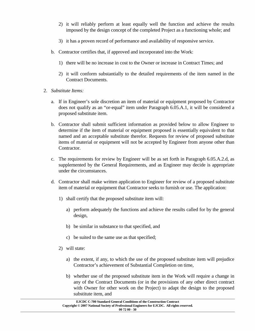
EJCDC C-700 Standard General Conditions of the Construction Contract Copyright © 2007 National Society of Professional Engineers for EJCDC. All rights reserved.
00 72 00 - 30
2) it will reliably perform at least equally well the function and achieve the results imposed by the design concept of the completed Project as a functioning whole; and
3) it has a proven record of performance and availability of responsive service.
b. Contractor certifies that, if approved and incorporated into the Work:
1) there will be no increase in cost to the Owner or increase in Contract Times; and
2) it will conform substantially to the detailed requirements of the item named in the Contract Documents.
2. Substitute Items:
a. If in Engineer’s sole discretion an item of material or equipment proposed by Contractor does not qualify as an “or-equal” item under Paragraph 6.05.A.1, it will be considered a proposed substitute item.
b. Contractor shall submit sufficient information as provided below to allow Engineer to determine if the item of material or equipment proposed is essentially equivalent to that named and an acceptable substitute therefor. Requests for review of proposed substitute items of material or equipment will not be accepted by Engineer from anyone other than Contractor.
c. The requirements for review by Engineer will be as set forth in Paragraph 6.05.A.2.d, as supplemented by the General Requirements, and as Engineer may decide is appropriate under the circumstances.
d. Contractor shall make written application to Engineer for review of a proposed substitute item of material or equipment that Contractor seeks to furnish or use. The application:
1) shall certify that the proposed substitute item will:
a) perform adequately the functions and achieve the results called for by the general design,
b) be similar in substance to that specified, and
c) be suited to the same use as that specified;
2) will state:
a) the extent, if any, to which the use of the proposed substitute item will prejudice Contractor’s achievement of Substantial Completion on time,
b) whether use of the proposed substitute item in the Work will require a change in any of the Contract Documents (or in the provisions of any other direct contract with Owner for other work on the Project) to adapt the design to the proposed substitute item, and

EJCDC C-700 Standard General Conditions of the Construction Contract Copyright © 2007 National Society of Professional Engineers for EJCDC. All rights reserved.
00 72 00 - 31
c) whether incorporation or use of the proposed substitute item in connection with the Work is subject to payment of any license fee or royalty;
3) will identify:
a) all variations of the proposed substitute item from that specified, and
b) available engineering, sales, maintenance, repair, and replacement services; and
4) shall contain an itemized estimate of all costs or credits that will result directly or indirectly from use of such substitute item, including costs of redesign and claims of other contractors affected by any resulting change.
B. Substitute Construction Methods or Procedures: If a specific means, method, technique, sequence, or procedure of construction is expressly required by the Contract Documents, Contractor may furnish or utilize a substitute means, method, technique, sequence, or procedure of construction approved by Engineer. Contractor shall submit sufficient information to allow Engineer, in Engineer’s sole discretion, to determine that the substitute proposed is equivalent to that expressly called for by the Contract Documents. The requirements for review by Engineer will be similar to those provided in Paragraph 6.05.A.2.
C. Engineer’s Evaluation: Engineer will be allowed a reasonable time within which to evaluate each proposal or submittal made pursuant to Paragraphs 6.05.A and 6.05.B. Engineer may require Contractor to furnish additional data about the proposed substitute item. Engineer will be the sole judge of acceptability. No “or equal” or substitute will be ordered, installed or utilized until Engineer’s review is complete, which will be evidenced by a Change Order in the case of a substitute and an approved Shop Drawing for an “or equal.” Engineer will advise Contractor in writing of any negative determination.
D. Special Guarantee: Owner may require Contractor to furnish at Contractor’s expense a special performance guarantee or other surety with respect to any substitute.
E. Engineer’s Cost Reimbursement: Engineer will record Engineer’s costs in evaluating a substitute proposed or submitted by Contractor pursuant to Paragraphs 6.05.A.2 and 6.05.B. Whether or not Engineer approves a substitute so proposed or submitted by Contractor, Contractor shall reimburse Owner for the reasonable charges of Engineer for evaluating each such proposed substitute. Contractor shall also reimburse Owner for the reasonable charges of Engineer for making changes in the Contract Documents (or in the provisions of any other direct contract with Owner) resulting from the acceptance of each proposed substitute.
F. Contractor’s Expense: Contractor shall provide all data in support of any proposed substitute or “or-equal” at Contractor’s expense.
6.06 Concerning Subcontractors, Suppliers, and Others
A. Contractor shall not employ any Subcontractor, Supplier, or other individual or entity (including those acceptable to Owner as indicated in Paragraph 6.06.B), whether initially or as a replacement, against whom Owner may have reasonable objection. Contractor shall not be

EJCDC C-700 Standard General Conditions of the Construction Contract Copyright © 2007 National Society of Professional Engineers for EJCDC. All rights reserved.
00 72 00 - 32
required to employ any Subcontractor, Supplier, or other individual or entity to furnish or perform any of the Work against whom Contractor has reasonable objection.
B. If the Supplementary Conditions require the identity of certain Subcontractors, Suppliers, or other individuals or entities to be submitted to Owner in advance for acceptance by Owner by a specified date prior to the Effective Date of the Agreement, and if Contractor has submitted a list thereof in accordance with the Supplementary Conditions, Owner’s acceptance (either in writing or by failing to make written objection thereto by the date indicated for acceptance or objection in the Bidding Documents or the Contract Documents) of any such Subcontractor, Supplier, or other individual or entity so identified may be revoked on the basis of reasonable objection after due investigation. Contractor shall submit an acceptable replacement for the rejected Subcontractor, Supplier, or other individual or entity, and the Contract Price will be adjusted by the difference in the cost occasioned by such replacement, and an appropriate Change Order will be issued. No acceptance by Owner of any such Subcontractor, Supplier, or other individual or entity, whether initially or as a replacement, shall constitute a waiver of any right of Owner or Engineer to reject defective Work.
C. Contractor shall be fully responsible to Owner and Engineer for all acts and omissions of the Subcontractors, Suppliers, and other individuals or entities performing or furnishing any of the Work just as Contractor is responsible for Contractor’s own acts and omissions. Nothing in the Contract Documents:
1. shall create for the benefit of any such Subcontractor, Supplier, or other individual or entity any contractual relationship between Owner or Engineer and any such Subcontractor, Supplier or other individual or entity; nor
2. shall create any obligation on the part of Owner or Engineer to pay or to see to the payment of any moneys due any such Subcontractor, Supplier, or other individual or entity except as may otherwise be required by Laws and Regulations.
D. Contractor shall be solely responsible for scheduling and coordinating the Work of Subcontractors, Suppliers, and other individuals or entities performing or furnishing any of the Work under a direct or indirect contract with Contractor.
E. Contractor shall require all Subcontractors, Suppliers, and such other individuals or entities performing or furnishing any of the Work to communicate with Engineer through Contractor.
F. The divisions and sections of the Specifications and the identifications of any Drawings shall not control Contractor in dividing the Work among Subcontractors or Suppliers or delineating the Work to be performed by any specific trade.
G. All Work performed for Contractor by a Subcontractor or Supplier will be pursuant to an appropriate agreement between Contractor and the Subcontractor or Supplier which specifically binds the Subcontractor or Supplier to the applicable terms and conditions of the Contract Documents for the benefit of Owner and Engineer. Whenever any such agreement is with a Subcontractor or Supplier who is listed as a loss payee on the property insurance provided in Paragraph 5.06, the agreement between the Contractor and the Subcontractor or Supplier will contain provisions whereby the Subcontractor or Supplier waives all rights against Owner,

EJCDC C-700 Standard General Conditions of the Construction Contract Copyright © 2007 National Society of Professional Engineers for EJCDC. All rights reserved.
00 72 00 - 33
Contractor, Engineer, and all other individuals or entities identified in the Supplementary Conditions to be listed as insureds or loss payees (and the officers, directors, members, partners, employees, agents, consultants, and subcontractors of each and any of them) for all losses and damages caused by, arising out of, relating to, or resulting from any of the perils or causes of loss covered by such policies and any other property insurance applicable to the Work. If the insurers on any such policies require separate waiver forms to be signed by any Subcontractor or Supplier, Contractor will obtain the same.
6.07 Patent Fees and Royalties
A. Contractor shall pay all license fees and royalties and assume all costs incident to the use in the performance of the Work or the incorporation in the Work of any invention, design, process, product, or device which is the subject of patent rights or copyrights held by others. If a particular invention, design, process, product, or device is specified in the Contract Documents for use in the performance of the Work and if, to the actual knowledge of Owner or Engineer, its use is subject to patent rights or copyrights calling for the payment of any license fee or royalty to others, the existence of such rights shall be disclosed by Owner in the Contract Documents.
B. To the fullest extent permitted by Laws and Regulations, Owner shall indemnify and hold harmless Contractor, and its officers, directors, members, partners, employees, agents, consultants, and subcontractors from and against all claims, costs, losses, and damages (including but not limited to all fees and charges of engineers, architects, attorneys, and other professionals, and all court or arbitration or other dispute resolution costs) arising out of or relating to any infringement of patent rights or copyrights incident to the use in the performance of the Work or resulting from the incorporation in the Work of any invention, design, process, product, or device specified in the Contract Documents, but not identified as being subject to payment of any license fee or royalty to others required by patent rights or copyrights.
C. To the fullest extent permitted by Laws and Regulations, Contractor shall indemnify and hold harmless Owner and Engineer, and the officers, directors, members, partners, employees, agents, consultants and subcontractors of each and any of them from and against all claims, costs, losses, and damages (including but not limited to all fees and charges of engineers, architects, attorneys, and other professionals and all court or arbitration or other dispute resolution costs) arising out of or relating to any infringement of patent rights or copyrights incident to the use in the performance of the Work or resulting from the incorporation in the Work of any invention, design, process, product, or device not specified in the Contract Documents.
6.08 Permits
A. Unless otherwise provided in the Supplementary Conditions, Contractor shall obtain and pay for all construction permits and licenses. Owner shall assist Contractor, when necessary, in obtaining such permits and licenses. Contractor shall pay all governmental charges and inspection fees necessary for the prosecution of the Work which are applicable at the time of opening of Bids, or, if there are no Bids, on the Effective Date of the Agreement. Owner shall pay all charges of utility owners for connections for providing permanent service to the Work.

EJCDC C-700 Standard General Conditions of the Construction Contract Copyright © 2007 National Society of Professional Engineers for EJCDC. All rights reserved.
00 72 00 - 34
6.09 Laws and Regulations
A. Contractor shall give all notices required by and shall comply with all Laws and Regulations applicable to the performance of the Work. Except where otherwise expressly required by applicable Laws and Regulations, neither Owner nor Engineer shall be responsible for monitoring Contractor’s compliance with any Laws or Regulations.
B. If Contractor performs any Work knowing or having reason to know that it is contrary to Laws or Regulations, Contractor shall bear all claims, costs, losses, and damages (including but not limited to all fees and charges of engineers, architects, attorneys, and other professionals and all court or arbitration or other dispute resolution costs) arising out of or relating to such Work. However, it shall not be Contractor’s responsibility to make certain that the Specifications and Drawings are in accordance with Laws and Regulations, but this shall not relieve Contractor of Contractor’s obligations under Paragraph 3.03.
C. Changes in Laws or Regulations not known at the time of opening of Bids (or, on the Effective Date of the Agreement if there were no Bids) having an effect on the cost or time of performance of the Work shall be the subject of an adjustment in Contract Price or Contract Times. If Owner and Contractor are unable to agree on entitlement to or on the amount or extent, if any, of any such adjustment, a Claim may be made therefor as provided in Paragraph 10.05.
6.10 Taxes
A. Contractor shall pay all sales, consumer, use, and other similar taxes required to be paid by Contractor in accordance with the Laws and Regulations of the place of the Project which are applicable during the performance of the Work.
6.11 Use of Site and Other Areas
A. Limitation on Use of Site and Other Areas:
1. Contractor shall confine construction equipment, the storage of materials and equipment, and the operations of workers to the Site and other areas permitted by Laws and Regulations, and shall not unreasonably encumber the Site and other areas with construction equipment or other materials or equipment. Contractor shall assume full responsibility for any damage to any such land or area, or to the owner or occupant thereof, or of any adjacent land or areas resulting from the performance of the Work.
2. Should any claim be made by any such owner or occupant because of the performance of the Work, Contractor shall promptly settle with such other party by negotiation or otherwise resolve the claim by arbitration or other dispute resolution proceeding or at law.
3. To the fullest extent permitted by Laws and Regulations, Contractor shall indemnify and hold harmless Owner and Engineer, and the officers, directors, members, partners, employees, agents, consultants and subcontractors of each and any of them from and against all claims, costs, losses, and damages (including but not limited to all fees and charges of engineers, architects, attorneys, and other professionals and all court or arbitration or other dispute resolution costs) arising out of or relating to any claim or action, legal or equitable, brought

EJCDC C-700 Standard General Conditions of the Construction Contract Copyright © 2007 National Society of Professional Engineers for EJCDC. All rights reserved.
00 72 00 - 35
by any such owner or occupant against Owner, Engineer, or any other party indemnified hereunder to the extent caused by or based upon Contractor’s performance of the Work.
B. Removal of Debris During Performance of the Work: During the progress of the Work Contractor shall keep the Site and other areas free from accumulations of waste materials, rubbish, and other debris. Removal and disposal of such waste materials, rubbish, and other debris shall conform to applicable Laws and Regulations.
C. Cleaning: Prior to Substantial Completion of the Work Contractor shall clean the Site and the Work and make it ready for utilization by Owner. At the completion of the Work Contractor shall remove from the Site all tools, appliances, construction equipment and machinery, and surplus materials and shall restore to original condition all property not designated for alteration by the Contract Documents.
D. Loading Structures: Contractor shall not load nor permit any part of any structure to be loaded in any manner that will endanger the structure, nor shall Contractor subject any part of the Work or adjacent property to stresses or pressures that will endanger it.
6.12 Record Documents
A. Contractor shall maintain in a safe place at the Site one record copy of all Drawings, Specifications, Addenda, Change Orders, Work Change Directives, Field Orders, and written interpretations and clarifications in good order and annotated to show changes made during construction. These record documents together with all approved Samples and a counterpart of all approved Shop Drawings will be available to Engineer for reference. Upon completion of the Work, these record documents, Samples, and Shop Drawings will be delivered to Engineer for Owner.
6.13 Safety and Protection
A. Contractor shall be solely responsible for initiating, maintaining and supervising all safety precautions and programs in connection with the Work. Such responsibility does not relieve Subcontractors of their responsibility for the safety of persons or property in the performance of their work, nor for compliance with applicable safety Laws and Regulations. Contractor shall take all necessary precautions for the safety of, and shall provide the necessary protection to prevent damage, injury or loss to:
1. all persons on the Site or who may be affected by the Work;
2. all the Work and materials and equipment to be incorporated therein, whether in storage on or off the Site; and
3. other property at the Site or adjacent thereto, including trees, shrubs, lawns, walks, pavements, roadways, structures, utilities, and Underground Facilities not designated for removal, relocation, or replacement in the course of construction.
B. Contractor shall comply with all applicable Laws and Regulations relating to the safety of persons or property, or to the protection of persons or property from damage, injury, or loss; and

EJCDC C-700 Standard General Conditions of the Construction Contract Copyright © 2007 National Society of Professional Engineers for EJCDC. All rights reserved.
00 72 00 - 36
shall erect and maintain all necessary safeguards for such safety and protection. Contractor shall notify owners of adjacent property and of Underground Facilities and other utility owners when prosecution of the Work may affect them, and shall cooperate with them in the protection, removal, relocation, and replacement of their property.
C. Contractor shall comply with the applicable requirements of Owner’s safety programs, if any. The Supplementary Conditions identify any Owner’s safety programs that are applicable to the Work.
D. Contractor shall inform Owner and Engineer of the specific requirements of Contractor’s safety program with which Owner’s and Engineer’s employees and representatives must comply while at the Site.
E. All damage, injury, or loss to any property referred to in Paragraph 6.13.A.2 or 6.13.A.3 caused, directly or indirectly, in whole or in part, by Contractor, any Subcontractor, Supplier, or any other individual or entity directly or indirectly employed by any of them to perform any of the Work, or anyone for whose acts any of them may be liable, shall be remedied by Contractor (except damage or loss attributable to the fault of Drawings or Specifications or to the acts or omissions of Owner or Engineer or anyone employed by any of them, or anyone for whose acts any of them may be liable, and not attributable, directly or indirectly, in whole or in part, to the fault or negligence of Contractor or any Subcontractor, Supplier, or other individual or entity directly or indirectly employed by any of them).
F. Contractor’s duties and responsibilities for safety and for protection of the Work shall continue until such time as all the Work is completed and Engineer has issued a notice to Owner and Contractor in accordance with Paragraph 14.07.B that the Work is acceptable (except as otherwise expressly provided in connection with Substantial Completion).
6.14 Safety Representative
A. Contractor shall designate a qualified and experienced safety representative at the Site whose duties and responsibilities shall be the prevention of accidents and the maintaining and supervising of safety precautions and programs.
6.15 Hazard Communication Programs
A. Contractor shall be responsible for coordinating any exchange of material safety data sheets or other hazard communication information required to be made available to or exchanged between or among employers at the Site in accordance with Laws or Regulations.
6.16 Emergencies
A. In emergencies affecting the safety or protection of persons or the Work or property at the Site or adjacent thereto, Contractor is obligated to act to prevent threatened damage, injury, or loss. Contractor shall give Engineer prompt written notice if Contractor believes that any significant changes in the Work or variations from the Contract Documents have been caused thereby or are required as a result thereof. If Engineer determines that a change in the Contract Documents is

EJCDC C-700 Standard General Conditions of the Construction Contract Copyright © 2007 National Society of Professional Engineers for EJCDC. All rights reserved.
00 72 00 - 37
required because of the action taken by Contractor in response to such an emergency, a Work Change Directive or Change Order will be issued.
6.17 Shop Drawings and Samples
A. Contractor shall submit Shop Drawings and Samples to Engineer for review and approval in accordance with the accepted Schedule of Submittals (as required by Paragraph 2.07). Each submittal will be identified as Engineer may require.
1. Shop Drawings:
a. Submit number of copies specified in the General Requirements.
b. Data shown on the Shop Drawings will be complete with respect to quantities, dimensions, specified performance and design criteria, materials, and similar data to show Engineer the services, materials, and equipment Contractor proposes to provide and to enable Engineer to review the information for the limited purposes required by Paragraph 6.17.D.
2. Samples:
a. Submit number of Samples specified in the Specifications.
b. Clearly identify each Sample as to material, Supplier, pertinent data such as catalog numbers, the use for which intended and other data as Engineer may require to enable Engineer to review the submittal for the limited purposes required by Paragraph 6.17.D.
B. Where a Shop Drawing or Sample is required by the Contract Documents or the Schedule of Submittals, any related Work performed prior to Engineer’s review and approval of the pertinent submittal will be at the sole expense and responsibility of Contractor.
C. Submittal Procedures:
1. Before submitting each Shop Drawing or Sample, Contractor shall have:
a. reviewed and coordinated each Shop Drawing or Sample with other Shop Drawings and Samples and with the requirements of the Work and the Contract Documents;
b. determined and verified all field measurements, quantities, dimensions, specified performance and design criteria, installation requirements, materials, catalog numbers, and similar information with respect thereto;
c. determined and verified the suitability of all materials offered with respect to the indicated application, fabrication, shipping, handling, storage, assembly, and installation pertaining to the performance of the Work; and
d. determined and verified all information relative to Contractor’s responsibilities for means, methods, techniques, sequences, and procedures of construction, and safety precautions and programs incident thereto.
EJCDC C-700 Standard General Conditions of the Construction Contract Copyright © 2007 National Society of Professional Engineers for EJCDC. All rights reserved.
00 72 00 - 38
2. Each submittal shall bear a stamp or specific written certification that Contractor has satisfied Contractor’s obligations under the Contract Documents with respect to Contractor’s review and approval of that submittal.
3. With each submittal, Contractor shall give Engineer specific written notice of any variations that the Shop Drawing or Sample may have from the requirements of the Contract Documents. This notice shall be both a written communication separate from the Shop Drawings or Sample submittal; and, in addition, by a specific notation made on each Shop Drawing or Sample submitted to Engineer for review and approval of each such variation.
D. Engineer’s Review:
1. Engineer will provide timely review of Shop Drawings and Samples in accordance with the Schedule of Submittals acceptable to Engineer. Engineer’s review and approval will be only to determine if the items covered by the submittals will, after installation or incorporation in the Work, conform to the information given in the Contract Documents and be compatible with the design concept of the completed Project as a functioning whole as indicated by the Contract Documents.
2. Engineer’s review and approval will not extend to means, methods, techniques, sequences, or procedures of construction (except where a particular means, method, technique, sequence, or procedure of construction is specifically and expressly called for by the Contract Documents) or to safety precautions or programs incident thereto. The review and approval of a separate item as such will not indicate approval of the assembly in which the item functions.
3. Engineer’s review and approval shall not relieve Contractor from responsibility for any variation from the requirements of the Contract Documents unless Contractor has complied with the requirements of Paragraph 6.17.C.3 and Engineer has given written approval of each such variation by specific written notation thereof incorporated in or accompanying the Shop Drawing or Sample. Engineer’s review and approval shall not relieve Contractor from responsibility for complying with the requirements of Paragraph 6.17.C.1.
E. Resubmittal Procedures:
1. Contractor shall make corrections required by Engineer and shall return the required number of corrected copies of Shop Drawings and submit, as required, new Samples for review and approval. Contractor shall direct specific attention in writing to revisions other than the corrections called for by Engineer on previous submittals.
6.18 Continuing the Work
A. Contractor shall carry on the Work and adhere to the Progress Schedule during all disputes or disagreements with Owner. No Work shall be delayed or postponed pending resolution of any disputes or disagreements, except as permitted by Paragraph 15.04 or as Owner and Contractor may otherwise agree in writing.

EJCDC C-700 Standard General Conditions of the Construction Contract Copyright © 2007 National Society of Professional Engineers for EJCDC. All rights reserved.
00 72 00 - 39
6.19 Contractor’s General Warranty and Guarantee
A. Contractor warrants and guarantees to Owner that all Work will be in accordance with the Contract Documents and will not be defective. Engineer and its officers, directors, members, partners, employees, agents, consultants, and subcontractors shall be entitled to rely on representation of Contractor’s warranty and guarantee.
B. Contractor’s warranty and guarantee hereunder excludes defects or damage caused by:
1. abuse, modification, or improper maintenance or operation by persons other than Contractor, Subcontractors, Suppliers, or any other individual or entity for whom Contractor is responsible; or
2. normal wear and tear under normal usage.
C. Contractor’s obligation to perform and complete the Work in accordance with the Contract Documents shall be absolute. None of the following will constitute an acceptance of Work that is not in accordance with the Contract Documents or a release of Contractor’s obligation to perform the Work in accordance with the Contract Documents:
1. observations by Engineer;
2. recommendation by Engineer or payment by Owner of any progress or final payment;
3. the issuance of a certificate of Substantial Completion by Engineer or any payment related thereto by Owner;
4. use or occupancy of the Work or any part thereof by Owner;
5. any review and approval of a Shop Drawing or Sample submittal or the issuance of a notice of acceptability by Engineer;
6. any inspection, test, or approval by others; or
7. any correction of defective Work by Owner.
6.20 Indemnification
A. To the fullest extent permitted by Laws and Regulations, Contractor shall indemnify and hold harmless Owner and Engineer, and the officers, directors, members, partners, employees, agents, consultants and subcontractors of each and any of them from and against all claims, costs, losses, and damages (including but not limited to all fees and charges of engineers, architects, attorneys, and other professionals and all court or arbitration or other dispute resolution costs) arising out of or relating to the performance of the Work, provided that any such claim, cost, loss, or damage is attributable to bodily injury, sickness, disease, or death, or to injury to or destruction of tangible property (other than the Work itself), including the loss of use resulting therefrom but only to the extent caused by any negligent act or omission of Contractor, any Subcontractor, any Supplier, or any individual or entity directly or indirectly employed by any of them to perform any of the Work or anyone for whose acts any of them may be liable .

EJCDC C-700 Standard General Conditions of the Construction Contract Copyright © 2007 National Society of Professional Engineers for EJCDC. All rights reserved.
00 72 00 - 40
B. In any and all claims against Owner or Engineer or any of their officers, directors, members, partners, employees, agents, consultants, or subcontractors by any employee (or the survivor or personal representative of such employee) of Contractor, any Subcontractor, any Supplier, or any individual or entity directly or indirectly employed by any of them to perform any of the Work, or anyone for whose acts any of them may be liable, the indemnification obligation under Paragraph 6.20.A shall not be limited in any way by any limitation on the amount or type of damages, compensation, or benefits payable by or for Contractor or any such Subcontractor, Supplier, or other individual or entity under workers’ compensation acts, disability benefit acts, or other employee benefit acts.
C. The indemnification obligations of Contractor under Paragraph 6.20.A shall not extend to the liability of Engineer and Engineer’s officers, directors, members, partners, employees, agents, consultants and subcontractors arising out of:
1. the preparation or approval of, or the failure to prepare or approve maps, Drawings, opinions, reports, surveys, Change Orders, designs, or Specifications; or
2. giving directions or instructions, or failing to give them, if that is the primary cause of the injury or damage.
6.21 Delegation of Professional Design Services
A. Contractor will not be required to provide professional design services unless such services are specifically required by the Contract Documents for a portion of the Work or unless such services are required to carry out Contractor’s responsibilities for construction means, methods, techniques, sequences and procedures. Contractor shall not be required to provide professional services in violation of applicable law.
B. If professional design services or certifications by a design professional related to systems, materials or equipment are specifically required of Contractor by the Contract Documents, Owner and Engineer will specify all performance and design criteria that such services must satisfy. Contractor shall cause such services or certifications to be provided by a properly licensed professional, whose signature and seal shall appear on all drawings, calculations, specifications, certifications, Shop Drawings and other submittals prepared by such professional. Shop Drawings and other submittals related to the Work designed or certified by such professional, if prepared by others, shall bear such professional’s written approval when submitted to Engineer.
C. Owner and Engineer shall be entitled to rely upon the adequacy, accuracy and completeness of the services, certifications or approvals performed by such design professionals, provided Owner and Engineer have specified to Contractor all performance and design criteria that such services must satisfy.
D. Pursuant to this Paragraph 6.21, Engineer’s review and approval of design calculations and design drawings will be only for the limited purpose of checking for conformance with performance and design criteria given and the design concept expressed in the Contract Documents. Engineer’s review and approval of Shop Drawings and other submittals (except design calculations and design drawings) will be only for the purpose stated in Paragraph 6.17.D.1.

EJCDC C-700 Standard General Conditions of the Construction Contract Copyright © 2007 National Society of Professional Engineers for EJCDC. All rights reserved.
00 72 00 - 41
E. Contractor shall not be responsible for the adequacy of the performance or design criteria required by the Contract Documents.
ARTICLE 7 – OTHER WORK AT THE SITE
7.01 Related Work at Site
A. Owner may perform other work related to the Project at the Site with Owner’s employees, or through other direct contracts therefor, or have other work performed by utility owners. If such other work is not noted in the Contract Documents, then:
1. written notice thereof will be given to Contractor prior to starting any such other work; and
2. if Owner and Contractor are unable to agree on entitlement to or on the amount or extent, if any, of any adjustment in the Contract Price or Contract Times that should be allowed as a result of such other work, a Claim may be made therefor as provided in Paragraph 10.05.
B. Contractor shall afford each other contractor who is a party to such a direct contract, each utility owner, and Owner, if Owner is performing other work with Owner’s employees, proper and safe access to the Site, provide a reasonable opportunity for the introduction and storage of materials and equipment and the execution of such other work, and properly coordinate the Work with theirs. Contractor shall do all cutting, fitting, and patching of the Work that may be required to properly connect or otherwise make its several parts come together and properly integrate with such other work. Contractor shall not endanger any work of others by cutting, excavating, or otherwise altering such work; provided, however, that Contractor may cut or alter others' work with the written consent of Engineer and the others whose work will be affected. The duties and responsibilities of Contractor under this Paragraph are for the benefit of such utility owners and other contractors to the extent that there are comparable provisions for the benefit of Contractor in said direct contracts between Owner and such utility owners and other contractors.
C. If the proper execution or results of any part of Contractor’s Work depends upon work performed by others under this Article 7, Contractor shall inspect such other work and promptly report to Engineer in writing any delays, defects, or deficiencies in such other work that render it unavailable or unsuitable for the proper execution and results of Contractor’s Work. Contractor’s failure to so report will constitute an acceptance of such other work as fit and proper for integration with Contractor’s Work except for latent defects and deficiencies in such other work.
7.02 Coordination
A. If Owner intends to contract with others for the performance of other work on the Project at the Site, the following will be set forth in Supplementary Conditions:
1. the individual or entity who will have authority and responsibility for coordination of the activities among the various contractors will be identified;
2. the specific matters to be covered by such authority and responsibility will be itemized; and
3. the extent of such authority and responsibilities will be provided.

EJCDC C-700 Standard General Conditions of the Construction Contract Copyright © 2007 National Society of Professional Engineers for EJCDC. All rights reserved.
00 72 00 - 42
B. Unless otherwise provided in the Supplementary Conditions, Owner shall have sole authority and responsibility for such coordination.
7.03 Legal Relationships
A. Paragraphs 7.01.A and 7.02 are not applicable for utilities not under the control of Owner.
B. Each other direct contract of Owner under Paragraph 7.01.A shall provide that the other contractor is liable to Owner and Contractor for the reasonable direct delay and disruption costs incurred by Contractor as a result of the other contractor’s wrongful actions or inactions.
C. Contractor shall be liable to Owner and any other contractor under direct contract to Owner for the reasonable direct delay and disruption costs incurred by such other contractor as a result of Contractor’s wrongful action or inactions.
ARTICLE 8 – OWNER’S RESPONSIBILITIES
8.01 Communications to Contractor
A. Except as otherwise provided in these General Conditions, Owner shall issue all communications to Contractor through Engineer.
8.02 Replacement of Engineer
A. In case of termination of the employment of Engineer, Owner shall appoint an engineer to whom Contractor makes no reasonable objection, whose status under the Contract Documents shall be that of the former Engineer.
8.03 Furnish Data
A. Owner shall promptly furnish the data required of Owner under the Contract Documents.
8.04 Pay When Due
A. Owner shall make payments to Contractor when they are due as provided in Paragraphs 14.02.C and 14.07.C.
8.05 Lands and Easements; Reports and Tests
A. Owner’s duties with respect to providing lands and easements and providing engineering surveys to establish reference points are set forth in Paragraphs 4.01 and 4.05. Paragraph 4.02 refers to Owner’s identifying and making available to Contractor copies of reports of explorations and tests of subsurface conditions and drawings of physical conditions relating to existing surface or subsurface structures at the Site.
8.06 Insurance
A. Owner’s responsibilities, if any, with respect to purchasing and maintaining liability and property insurance are set forth in Article 5.

EJCDC C-700 Standard General Conditions of the Construction Contract Copyright © 2007 National Society of Professional Engineers for EJCDC. All rights reserved.
00 72 00 - 43
8.07 Change Orders
A. Owner is obligated to execute Change Orders as indicated in Paragraph 10.03.
8.08 Inspections, Tests, and Approvals
A. Owner’s responsibility with respect to certain inspections, tests, and approvals is set forth in Paragraph 13.03.B.
8.09 Limitations on Owner’s Responsibilities
A. The Owner shall not supervise, direct, or have control or authority over, nor be responsible for, Contractor’s means, methods, techniques, sequences, or procedures of construction, or the safety precautions and programs incident thereto, or for any failure of Contractor to comply with Laws and Regulations applicable to the performance of the Work. Owner will not be responsible for Contractor’s failure to perform the Work in accordance with the Contract Documents.
8.10 Undisclosed Hazardous Environmental Condition
A. Owner’s responsibility in respect to an undisclosed Hazardous Environmental Condition is set forth in Paragraph 4.06.
8.11 Evidence of Financial Arrangements
A. Upon request of Contractor, Owner shall furnish Contractor reasonable evidence that financial arrangements have been made to satisfy Owner’s obligations under the Contract Documents.
8.12 Compliance with Safety Program
A. While at the Site, Owner’s employees and representatives shall comply with the specific applicable requirements of Contractor’s safety programs of which Owner has been informed pursuant to Paragraph 6.13.D.
ARTICLE 9 – ENGINEER’S STATUS DURING CONSTRUCTION
9.01 Owner’s Representative
A. Engineer will be Owner’s representative during the construction period. The duties and responsibilities and the limitations of authority of Engineer as Owner’s representative during construction are set forth in the Contract Documents.
9.02 Visits to Site
A. Engineer will make visits to the Site at intervals appropriate to the various stages of construction as Engineer deems necessary in order to observe as an experienced and qualified design professional the progress that has been made and the quality of the various aspects of Contractor’s executed Work. Based on information obtained during such visits and observations, Engineer, for the benefit of Owner, will determine, in general, if the Work is proceeding in accordance with the Contract Documents. Engineer will not be required to make exhaustive or

EJCDC C-700 Standard General Conditions of the Construction Contract Copyright © 2007 National Society of Professional Engineers for EJCDC. All rights reserved.
00 72 00 - 44
continuous inspections on the Site to check the quality or quantity of the Work. Engineer’s efforts will be directed toward providing for Owner a greater degree of confidence that the completed Work will conform generally to the Contract Documents. On the basis of such visits and observations, Engineer will keep Owner informed of the progress of the Work and will endeavor to guard Owner against defective Work.
B. Engineer’s visits and observations are subject to all the limitations on Engineer’s authority and responsibility set forth in Paragraph 9.09. Particularly, but without limitation, during or as a result of Engineer’s visits or observations of Contractor’s Work, Engineer will not supervise, direct, control, or have authority over or be responsible for Contractor’s means, methods, techniques, sequences, or procedures of construction, or the safety precautions and programs incident thereto, or for any failure of Contractor to comply with Laws and Regulations applicable to the performance of the Work.
9.03 Project Representative
A. If Owner and Engineer agree, Engineer will furnish a Resident Project Representative to assist Engineer in providing more extensive observation of the Work. The authority and responsibilities of any such Resident Project Representative and assistants will be as provided in the Supplementary Conditions, and limitations on the responsibilities thereof will be as provided in Paragraph 9.09. If Owner designates another representative or agent to represent Owner at the Site who is not Engineer’s consultant, agent or employee, the responsibilities and authority and limitations thereon of such other individual or entity will be as provided in the Supplementary Conditions.
9.04 Authorized Variations in Work
A. Engineer may authorize minor variations in the Work from the requirements of the Contract Documents which do not involve an adjustment in the Contract Price or the Contract Times and are compatible with the design concept of the completed Project as a functioning whole as indicated by the Contract Documents. These may be accomplished by a Field Order and will be binding on Owner and also on Contractor, who shall perform the Work involved promptly. If Owner or Contractor believes that a Field Order justifies an adjustment in the Contract Price or Contract Times, or both, and the parties are unable to agree on entitlement to or on the amount or extent, if any, of any such adjustment, a Claim may be made therefor as provided in Paragraph 10.05.
9.05 Rejecting Defective Work
A. Engineer will have authority to reject Work which Engineer believes to be defective, or that Engineer believes will not produce a completed Project that conforms to the Contract Documents or that will prejudice the integrity of the design concept of the completed Project as a functioning whole as indicated by the Contract Documents. Engineer will also have authority to require special inspection or testing of the Work as provided in Paragraph 13.04, whether or not the Work is fabricated, installed, or completed.

EJCDC C-700 Standard General Conditions of the Construction Contract Copyright © 2007 National Society of Professional Engineers for EJCDC. All rights reserved.
00 72 00 - 45
9.06 Shop Drawings, Change Orders and Payments
A. In connection with Engineer’s authority, and limitations thereof, as to Shop Drawings and Samples, see Paragraph 6.17.
B. In connection with Engineer’s authority, and limitations thereof, as to design calculations and design drawings submitted in response to a delegation of professional design services, if any, see Paragraph 6.21.
C. In connection with Engineer’s authority as to Change Orders, see Articles 10, 11, and 12.
D. In connection with Engineer’s authority as to Applications for Payment, see Article 14.
9.07 Determinations for Unit Price Work
A. Engineer will determine the actual quantities and classifications of Unit Price Work performed by Contractor. Engineer will review with Contractor the Engineer’s preliminary determinations on such matters before rendering a written decision thereon (by recommendation of an Application for Payment or otherwise). Engineer’s written decision thereon will be final and binding (except as modified by Engineer to reflect changed factual conditions or more accurate data) upon Owner and Contractor, subject to the provisions of Paragraph 10.05.
9.08 Decisions on Requirements of Contract Documents and Acceptability of Work
A. Engineer will be the initial interpreter of the requirements of the Contract Documents and judge of the acceptability of the Work thereunder. All matters in question and other matters between Owner and Contractor arising prior to the date final payment is due relating to the acceptability of the Work, and the interpretation of the requirements of the Contract Documents pertaining to the performance of the Work, will be referred initially to Engineer in writing within 30 days of the event giving rise to the question.
B. Engineer will, with reasonable promptness, render a written decision on the issue referred. If Owner or Contractor believes that any such decision entitles them to an adjustment in the Contract Price or Contract Times or both, a Claim may be made under Paragraph 10.05. The date of Engineer’s decision shall be the date of the event giving rise to the issues referenced for the purposes of Paragraph 10.05.B.
C. Engineer’s written decision on the issue referred will be final and binding on Owner and Contractor, subject to the provisions of Paragraph 10.05.
D. When functioning as interpreter and judge under this Paragraph 9.08, Engineer will not show partiality to Owner or Contractor and will not be liable in connection with any interpretation or decision rendered in good faith in such capacity.
9.09 Limitations on Engineer’s Authority and Responsibilities
A. Neither Engineer’s authority or responsibility under this Article 9 or under any other provision of the Contract Documents nor any decision made by Engineer in good faith either to exercise or not

EJCDC C-700 Standard General Conditions of the Construction Contract Copyright © 2007 National Society of Professional Engineers for EJCDC. All rights reserved.
00 72 00 - 46
exercise such authority or responsibility or the undertaking, exercise, or performance of any authority or responsibility by Engineer shall create, impose, or give rise to any duty in contract, tort, or otherwise owed by Engineer to Contractor, any Subcontractor, any Supplier, any other individual or entity, or to any surety for or employee or agent of any of them.
B. Engineer will not supervise, direct, control, or have authority over or be responsible for Contractor’s means, methods, techniques, sequences, or procedures of construction, or the safety precautions and programs incident thereto, or for any failure of Contractor to comply with Laws and Regulations applicable to the performance of the Work. Engineer will not be responsible for Contractor’s failure to perform the Work in accordance with the Contract Documents.
C. Engineer will not be responsible for the acts or omissions of Contractor or of any Subcontractor, any Supplier, or of any other individual or entity performing any of the Work.
D. Engineer’s review of the final Application for Payment and accompanying documentation and all maintenance and operating instructions, schedules, guarantees, bonds, certificates of inspection, tests and approvals, and other documentation required to be delivered by Paragraph 14.07.A will only be to determine generally that their content complies with the requirements of, and in the case of certificates of inspections, tests, and approvals that the results certified indicate compliance with, the Contract Documents.
E. The limitations upon authority and responsibility set forth in this Paragraph 9.09 shall also apply to the Resident Project Representative, if any, and assistants, if any.
9.10 Compliance with Safety Program
A. While at the Site, Engineer’s employees and representatives shall comply with the specific applicable requirements of Contractor’s safety programs of which Engineer has been informed pursuant to Paragraph 6.13.D.
ARTICLE 10 – CHANGES IN THE WORK; CLAIMS
10.01 Authorized Changes in the Work
A. Without invalidating the Contract and without notice to any surety, Owner may, at any time or from time to time, order additions, deletions, or revisions in the Work by a Change Order, or a Work Change Directive. Upon receipt of any such document, Contractor shall promptly proceed with the Work involved which will be performed under the applicable conditions of the Contract Documents (except as otherwise specifically provided).
B. If Owner and Contractor are unable to agree on entitlement to, or on the amount or extent, if any, of an adjustment in the Contract Price or Contract Times, or both, that should be allowed as a result of a Work Change Directive, a Claim may be made therefor as provided in Paragraph 10.05.

EJCDC C-700 Standard General Conditions of the Construction Contract Copyright © 2007 National Society of Professional Engineers for EJCDC. All rights reserved.
00 72 00 - 47
10.02 Unauthorized Changes in the Work
A. Contractor shall not be entitled to an increase in the Contract Price or an extension of the Contract Times with respect to any work performed that is not required by the Contract Documents as amended, modified, or supplemented as provided in Paragraph 3.04, except in the case of an emergency as provided in Paragraph 6.16 or in the case of uncovering Work as provided in Paragraph 13.04.D.
10.03 Execution of Change Orders
A. Owner and Contractor shall execute appropriate Change Orders recommended by Engineer covering:
1. changes in the Work which are: (i) ordered by Owner pursuant to Paragraph 10.01.A, (ii) required because of acceptance of defective Work under Paragraph 13.08.A or Owner’s correction of defective Work under Paragraph 13.09, or (iii) agreed to by the parties;
2. changes in the Contract Price or Contract Times which are agreed to by the parties, including any undisputed sum or amount of time for Work actually performed in accordance with a Work Change Directive; and
3. changes in the Contract Price or Contract Times which embody the substance of any written decision rendered by Engineer pursuant to Paragraph 10.05; provided that, in lieu of executing any such Change Order, an appeal may be taken from any such decision in accordance with the provisions of the Contract Documents and applicable Laws and Regulations, but during any such appeal, Contractor shall carry on the Work and adhere to the Progress Schedule as provided in Paragraph 6.18.A.
10.04 Notification to Surety
A. If the provisions of any bond require notice to be given to a surety of any change affecting the general scope of the Work or the provisions of the Contract Documents (including, but not limited to, Contract Price or Contract Times), the giving of any such notice will be Contractor’s responsibility. The amount of each applicable bond will be adjusted to reflect the effect of any such change.
10.05 Claims
A. Engineer’s Decision Required: All Claims, except those waived pursuant to Paragraph 14.09, shall be referred to the Engineer for decision. A decision by Engineer shall be required as a condition precedent to any exercise by Owner or Contractor of any rights or remedies either may otherwise have under the Contract Documents or by Laws and Regulations in respect of such Claims.
B. Notice: Written notice stating the general nature of each Claim shall be delivered by the claimant to Engineer and the other party to the Contract promptly (but in no event later than 30 days) after the start of the event giving rise thereto. The responsibility to substantiate a Claim shall rest with the party making the Claim. Notice of the amount or extent of the Claim, with supporting data

EJCDC C-700 Standard General Conditions of the Construction Contract Copyright © 2007 National Society of Professional Engineers for EJCDC. All rights reserved.
00 72 00 - 48
shall be delivered to the Engineer and the other party to the Contract within 60 days after the start of such event (unless Engineer allows additional time for claimant to submit additional or more accurate data in support of such Claim). A Claim for an adjustment in Contract Price shall be prepared in accordance with the provisions of Paragraph 12.01.B. A Claim for an adjustment in Contract Times shall be prepared in accordance with the provisions of Paragraph 12.02.B. Each Claim shall be accompanied by claimant’s written statement that the adjustment claimed is the entire adjustment to which the claimant believes it is entitled as a result of said event. The opposing party shall submit any response to Engineer and the claimant within 30 days after receipt of the claimant’s last submittal (unless Engineer allows additional time).
C. Engineer’s Action: Engineer will review each Claim and, within 30 days after receipt of the last submittal of the claimant or the last submittal of the opposing party, if any, take one of the following actions in writing:
1. deny the Claim in whole or in part;
2. approve the Claim; or
3. notify the parties that the Engineer is unable to resolve the Claim if, in the Engineer’s sole discretion, it would be inappropriate for the Engineer to do so. For purposes of further resolution of the Claim, such notice shall be deemed a denial.
D. In the event that Engineer does not take action on a Claim within said 30 days, the Claim shall be deemed denied.
E. Engineer’s written action under Paragraph 10.05.C or denial pursuant to Paragraphs 10.05.C.3 or 10.05.D will be final and binding upon Owner and Contractor, unless Owner or Contractor invoke the dispute resolution procedure set forth in Article 16 within 30 days of such action or denial.
F. No Claim for an adjustment in Contract Price or Contract Times will be valid if not submitted in accordance with this Paragraph 10.05.
ARTICLE 11 – COST OF THE WORK; ALLOWANCES; UNIT PRICE WORK
11.01 Cost of the Work
A. Costs Included: The term Cost of the Work means the sum of all costs, except those excluded in Paragraph 11.01.B, necessarily incurred and paid by Contractor in the proper performance of the Work. When the value of any Work covered by a Change Order or when a Claim for an adjustment in Contract Price is determined on the basis of Cost of the Work, the costs to be reimbursed to Contractor will be only those additional or incremental costs required because of the change in the Work or because of the event giving rise to the Claim. Except as otherwise may be agreed to in writing by Owner, such costs shall be in amounts no higher than those prevailing in the locality of the Project, shall not include any of the costs itemized in Paragraph 11.01.B, and shall include only the following items:

EJCDC C-700 Standard General Conditions of the Construction Contract Copyright © 2007 National Society of Professional Engineers for EJCDC. All rights reserved.
00 72 00 - 49
1. Payroll costs for employees in the direct employ of Contractor in the performance of the Work under schedules of job classifications agreed upon by Owner and Contractor. Such employees shall include, without limitation, superintendents, foremen, and other personnel employed full time on the Work. Payroll costs for employees not employed full time on the Work shall be apportioned on the basis of their time spent on the Work. Payroll costs shall include, but not be limited to, salaries and wages plus the cost of fringe benefits, which shall include social security contributions, unemployment, excise, and payroll taxes, workers’ compensation, health and retirement benefits, bonuses, sick leave, vacation and holiday pay applicable thereto. The expenses of performing Work outside of regular working hours, on Saturday, Sunday, or legal holidays, shall be included in the above to the extent authorized by Owner.
2. Cost of all materials and equipment furnished and incorporated in the Work, including costs of transportation and storage thereof, and Suppliers’ field services required in connection therewith. All cash discounts shall accrue to Contractor unless Owner deposits funds with Contractor with which to make payments, in which case the cash discounts shall accrue to Owner. All trade discounts, rebates and refunds and returns from sale of surplus materials and equipment shall accrue to Owner, and Contractor shall make provisions so that they may be obtained.
3. Payments made by Contractor to Subcontractors for Work performed by Subcontractors. If required by Owner, Contractor shall obtain competitive bids from subcontractors acceptable to Owner and Contractor and shall deliver such bids to Owner, who will then determine, with the advice of Engineer, which bids, if any, will be acceptable. If any subcontract provides that the Subcontractor is to be paid on the basis of Cost of the Work plus a fee, the Subcontractor’s Cost of the Work and fee shall be determined in the same manner as Contractor’s Cost of the Work and fee as provided in this Paragraph 11.01.
4. Costs of special consultants (including but not limited to engineers, architects, testing laboratories, surveyors, attorneys, and accountants) employed for services specifically related to the Work.
5. Supplemental costs including the following:
a. The proportion of necessary transportation, travel, and subsistence expenses of Contractor’s employees incurred in discharge of duties connected with the Work.
b. Cost, including transportation and maintenance, of all materials, supplies, equipment, machinery, appliances, office, and temporary facilities at the Site, and hand tools not owned by the workers, which are consumed in the performance of the Work, and cost, less market value, of such items used but not consumed which remain the property of Contractor.
c. Rentals of all construction equipment and machinery, and the parts thereof whether rented from Contractor or others in accordance with rental agreements approved by Owner with the advice of Engineer, and the costs of transportation, loading, unloading, assembly, dismantling, and removal thereof. All such costs shall be in accordance with the terms of

EJCDC C-700 Standard General Conditions of the Construction Contract Copyright © 2007 National Society of Professional Engineers for EJCDC. All rights reserved.
00 72 00 - 50
said rental agreements. The rental of any such equipment, machinery, or parts shall cease when the use thereof is no longer necessary for the Work.
d. Sales, consumer, use, and other similar taxes related to the Work, and for which Contractor is liable, as imposed by Laws and Regulations.
e. Deposits lost for causes other than negligence of Contractor, any Subcontractor, or anyone directly or indirectly employed by any of them or for whose acts any of them may be liable, and royalty payments and fees for permits and licenses.
f. Losses and damages (and related expenses) caused by damage to the Work, not compensated by insurance or otherwise, sustained by Contractor in connection with the performance of the Work (except losses and damages within the deductible amounts of property insurance established in accordance with Paragraph 5.06.D), provided such losses and damages have resulted from causes other than the negligence of Contractor, any Subcontractor, or anyone directly or indirectly employed by any of them or for whose acts any of them may be liable. Such losses shall include settlements made with the written consent and approval of Owner. No such losses, damages, and expenses shall be included in the Cost of the Work for the purpose of determining Contractor’s fee.
g. The cost of utilities, fuel, and sanitary facilities at the Site.
h. Minor expenses such as telegrams, long distance telephone calls, telephone service at the Site, express and courier services, and similar petty cash items in connection with the Work.
i. The costs of premiums for all bonds and insurance Contractor is required by the Contract Documents to purchase and maintain.
B. Costs Excluded: The term Cost of the Work shall not include any of the following items:
1. Payroll costs and other compensation of Contractor’s officers, executives, principals (of partnerships and sole proprietorships), general managers, safety managers, engineers, architects, estimators, attorneys, auditors, accountants, purchasing and contracting agents, expediters, timekeepers, clerks, and other personnel employed by Contractor, whether at the Site or in Contractor’s principal or branch office for general administration of the Work and not specifically included in the agreed upon schedule of job classifications referred to in Paragraph 11.01.A.1 or specifically covered by Paragraph 11.01.A.4, all of which are to be considered administrative costs covered by the Contractor’s fee.
2. Expenses of Contractor’s principal and branch offices other than Contractor’s office at the Site.
3. Any part of Contractor’s capital expenses, including interest on Contractor’s capital employed for the Work and charges against Contractor for delinquent payments.
4. Costs due to the negligence of Contractor, any Subcontractor, or anyone directly or indirectly employed by any of them or for whose acts any of them may be liable, including but not

EJCDC C-700 Standard General Conditions of the Construction Contract Copyright © 2007 National Society of Professional Engineers for EJCDC. All rights reserved.
00 72 00 - 51
limited to, the correction of defective Work, disposal of materials or equipment wrongly supplied, and making good any damage to property.
5. Other overhead or general expense costs of any kind and the costs of any item not specifically and expressly included in Paragraphs 11.01.A.
C. Contractor’s Fee: When all the Work is performed on the basis of cost-plus, Contractor’s fee shall be determined as set forth in the Agreement. When the value of any Work covered by a Change Order or when a Claim for an adjustment in Contract Price is determined on the basis of Cost of the Work, Contractor’s fee shall be determined as set forth in Paragraph 12.01.C.
D. Documentation: Whenever the Cost of the Work for any purpose is to be determined pursuant to Paragraphs 11.01.A and 11.01.B, Contractor will establish and maintain records thereof in accordance with generally accepted accounting practices and submit in a form acceptable to Engineer an itemized cost breakdown together with supporting data.
11.02 Allowances
A. It is understood that Contractor has included in the Contract Price all allowances so named in the Contract Documents and shall cause the Work so covered to be performed for such sums and by such persons or entities as may be acceptable to Owner and Engineer.
B. Cash Allowances:
1. Contractor agrees that:
a. the cash allowances include the cost to Contractor (less any applicable trade discounts) of materials and equipment required by the allowances to be delivered at the Site, and all applicable taxes; and
b. Contractor’s costs for unloading and handling on the Site, labor, installation, overhead, profit, and other expenses contemplated for the cash allowances have been included in the Contract Price and not in the allowances, and no demand for additional payment on account of any of the foregoing will be valid.
C. Contingency Allowance:
1. Contractor agrees that a contingency allowance, if any, is for the sole use of Owner to cover unanticipated costs.
D. Prior to final payment, an appropriate Change Order will be issued as recommended by Engineer to reflect actual amounts due Contractor on account of Work covered by allowances, and the Contract Price shall be correspondingly adjusted.
11.03 Unit Price Work
A. Where the Contract Documents provide that all or part of the Work is to be Unit Price Work, initially the Contract Price will be deemed to include for all Unit Price Work an amount equal to

EJCDC C-700 Standard General Conditions of the Construction Contract Copyright © 2007 National Society of Professional Engineers for EJCDC. All rights reserved.
00 72 00 - 52
the sum of the unit price for each separately identified item of Unit Price Work times the estimated quantity of each item as indicated in the Agreement.
B. The estimated quantities of items of Unit Price Work are not guaranteed and are solely for the purpose of comparison of Bids and determining an initial Contract Price. Determinations of the actual quantities and classifications of Unit Price Work performed by Contractor will be made by Engineer subject to the provisions of Paragraph 9.07.
C. Each unit price will be deemed to include an amount considered by Contractor to be adequate to cover Contractor’s overhead and profit for each separately identified item.
D. Owner or Contractor may make a Claim for an adjustment in the Contract Price in accordance with Paragraph 10.05 if:
1. the quantity of any item of Unit Price Work performed by Contractor differs materially and significantly from the estimated quantity of such item indicated in the Agreement; and
2. there is no corresponding adjustment with respect to any other item of Work; and
3. Contractor believes that Contractor is entitled to an increase in Contract Price as a result of having incurred additional expense or Owner believes that Owner is entitled to a decrease in Contract Price and the parties are unable to agree as to the amount of any such increase or decrease.
ARTICLE 12 – CHANGE OF CONTRACT PRICE; CHANGE OF CONTRACT TIMES
12.01 Change of Contract Price
A. The Contract Price may only be changed by a Change Order. Any Claim for an adjustment in the Contract Price shall be based on written notice submitted by the party making the Claim to the Engineer and the other party to the Contract in accordance with the provisions of Paragraph 10.05.
B. The value of any Work covered by a Change Order or of any Claim for an adjustment in the Contract Price will be determined as follows:
1. where the Work involved is covered by unit prices contained in the Contract Documents, by application of such unit prices to the quantities of the items involved (subject to the provisions of Paragraph 11.03); or
2. where the Work involved is not covered by unit prices contained in the Contract Documents, by a mutually agreed lump sum (which may include an allowance for overhead and profit not necessarily in accordance with Paragraph 12.01.C.2); or
3. where the Work involved is not covered by unit prices contained in the Contract Documents and agreement to a lump sum is not reached under Paragraph 12.01.B.2, on the basis of the Cost of the Work (determined as provided in Paragraph 11.01) plus a Contractor’s fee for overhead and profit (determined as provided in Paragraph 12.01.C).

EJCDC C-700 Standard General Conditions of the Construction Contract Copyright © 2007 National Society of Professional Engineers for EJCDC. All rights reserved.
00 72 00 - 53
C. Contractor’s Fee: The Contractor’s fee for overhead and profit shall be determined as follows:
1. a mutually acceptable fixed fee; or
2. if a fixed fee is not agreed upon, then a fee based on the following percentages of the various portions of the Cost of the Work:
a. for costs incurred under Paragraphs 11.01.A.1 and 11.01.A.2, the Contractor’s fee shall be 15 percent;
b. for costs incurred under Paragraph 11.01.A.3, the Contractor’s fee shall be five percent;
c. where one or more tiers of subcontracts are on the basis of Cost of the Work plus a fee and no fixed fee is agreed upon, the intent of Paragraphs 12.01.C.2.a and 12.01.C.2.b is that the Subcontractor who actually performs the Work, at whatever tier, will be paid a fee of 15 percent of the costs incurred by such Subcontractor under Paragraphs 11.01.A.1 and 11.01.A.2 and that any higher tier Subcontractor and Contractor will each be paid a fee of five percent of the amount paid to the next lower tier Subcontractor;
d. no fee shall be payable on the basis of costs itemized under Paragraphs 11.01.A.4, 11.01.A.5, and 11.01.B;
e. the amount of credit to be allowed by Contractor to Owner for any change which results in a net decrease in cost will be the amount of the actual net decrease in cost plus a deduction in Contractor’s fee by an amount equal to five percent of such net decrease; and
f. when both additions and credits are involved in any one change, the adjustment in Contractor’s fee shall be computed on the basis of the net change in accordance with Paragraphs 12.01.C.2.a through 12.01.C.2.e, inclusive.
12.02 Change of Contract Times
A. The Contract Times may only be changed by a Change Order. Any Claim for an adjustment in the Contract Times shall be based on written notice submitted by the party making the Claim to the Engineer and the other party to the Contract in accordance with the provisions of Paragraph 10.05.
B. Any adjustment of the Contract Times covered by a Change Order or any Claim for an adjustment in the Contract Times will be determined in accordance with the provisions of this Article 12.
12.03 Delays
A. Where Contractor is prevented from completing any part of the Work within the Contract Times due to delay beyond the control of Contractor, the Contract Times will be extended in an amount equal to the time lost due to such delay if a Claim is made therefor as provided in Paragraph 12.02.A. Delays beyond the control of Contractor shall include, but not be limited to, acts or

EJCDC C-700 Standard General Conditions of the Construction Contract Copyright © 2007 National Society of Professional Engineers for EJCDC. All rights reserved.
00 72 00 - 54
neglect by Owner, acts or neglect of utility owners or other contractors performing other work as contemplated by Article 7, fires, floods, epidemics, abnormal weather conditions, or acts of God.
B. If Owner, Engineer, or other contractors or utility owners performing other work for Owner as contemplated by Article 7, or anyone for whom Owner is responsible, delays, disrupts, or interferes with the performance or progress of the Work, then Contractor shall be entitled to an equitable adjustment in the Contract Price or the Contract Times, or both. Contractor’s entitlement to an adjustment of the Contract Times is conditioned on such adjustment being essential to Contractor’s ability to complete the Work within the Contract Times.
C. If Contractor is delayed in the performance or progress of the Work by fire, flood, epidemic, abnormal weather conditions, acts of God, acts or failures to act of utility owners not under the control of Owner, or other causes not the fault of and beyond control of Owner and Contractor, then Contractor shall be entitled to an equitable adjustment in Contract Times, if such adjustment is essential to Contractor’s ability to complete the Work within the Contract Times. Such an adjustment shall be Contractor’s sole and exclusive remedy for the delays described in this Paragraph 12.03.C.
D. Owner, Engineer, and their officers, directors, members, partners, employees, agents, consultants, or subcontractors shall not be liable to Contractor for any claims, costs, losses, or damages (including but not limited to all fees and charges of engineers, architects, attorneys, and other professionals and all court or arbitration or other dispute resolution costs) sustained by Contractor on or in connection with any other project or anticipated project.
E. Contractor shall not be entitled to an adjustment in Contract Price or Contract Times for delays within the control of Contractor. Delays attributable to and within the control of a Subcontractor or Supplier shall be deemed to be delays within the control of Contractor.
ARTICLE 13 – TESTS AND INSPECTIONS; CORRECTION, REMOVAL OR ACCEPTANCE OF DEFECTIVE WORK
13.01 Notice of Defects
A. Prompt notice of all defective Work of which Owner or Engineer has actual knowledge will be given to Contractor. Defective Work may be rejected, corrected, or accepted as provided in this Article 13.
13.02 Access to Work
A. Owner, Engineer, their consultants and other representatives and personnel of Owner, independent testing laboratories, and governmental agencies with jurisdictional interests will have access to the Site and the Work at reasonable times for their observation, inspection, and testing. Contractor shall provide them proper and safe conditions for such access and advise them of Contractor’s safety procedures and programs so that they may comply therewith as applicable.

EJCDC C-700 Standard General Conditions of the Construction Contract Copyright © 2007 National Society of Professional Engineers for EJCDC. All rights reserved.
00 72 00 - 55
13.03 Tests and Inspections
A. Contractor shall give Engineer timely notice of readiness of the Work for all required inspections, tests, or approvals and shall cooperate with inspection and testing personnel to facilitate required inspections or tests.
B. Owner shall employ and pay for the services of an independent testing laboratory to perform all inspections, tests, or approvals required by the Contract Documents except:
1. for inspections, tests, or approvals covered by Paragraphs 13.03.C and 13.03.D below;
2. that costs incurred in connection with tests or inspections conducted pursuant to Paragraph 13.04.B shall be paid as provided in Paragraph 13.04.C; and
3. as otherwise specifically provided in the Contract Documents.
C. If Laws or Regulations of any public body having jurisdiction require any Work (or part thereof) specifically to be inspected, tested, or approved by an employee or other representative of such public body, Contractor shall assume full responsibility for arranging and obtaining such inspections, tests, or approvals, pay all costs in connection therewith, and furnish Engineer the required certificates of inspection or approval.
D. Contractor shall be responsible for arranging and obtaining and shall pay all costs in connection with any inspections, tests, or approvals required for Owner’s and Engineer’s acceptance of materials or equipment to be incorporated in the Work; or acceptance of materials, mix designs, or equipment submitted for approval prior to Contractor’s purchase thereof for incorporation in the Work. Such inspections, tests, or approvals shall be performed by organizations acceptable to Owner and Engineer.
E. If any Work (or the work of others) that is to be inspected, tested, or approved is covered by Contractor without written concurrence of Engineer, Contractor shall, if requested by Engineer, uncover such Work for observation.
F. Uncovering Work as provided in Paragraph 13.03.E shall be at Contractor’s expense unless Contractor has given Engineer timely notice of Contractor’s intention to cover the same and Engineer has not acted with reasonable promptness in response to such notice.
13.04 Uncovering Work
A. If any Work is covered contrary to the written request of Engineer, it must, if requested by Engineer, be uncovered for Engineer’s observation and replaced at Contractor’s expense.
B. If Engineer considers it necessary or advisable that covered Work be observed by Engineer or inspected or tested by others, Contractor, at Engineer’s request, shall uncover, expose, or otherwise make available for observation, inspection, or testing as Engineer may require, that portion of the Work in question, furnishing all necessary labor, material, and equipment.

EJCDC C-700 Standard General Conditions of the Construction Contract Copyright © 2007 National Society of Professional Engineers for EJCDC. All rights reserved.
00 72 00 - 56
C. If it is found that the uncovered Work is defective, Contractor shall pay all claims, costs, losses, and damages (including but not limited to all fees and charges of engineers, architects, attorneys, and other professionals and all court or arbitration or other dispute resolution costs) arising out of or relating to such uncovering, exposure, observation, inspection, and testing, and of satisfactory replacement or reconstruction (including but not limited to all costs of repair or replacement of work of others); and Owner shall be entitled to an appropriate decrease in the Contract Price. If the parties are unable to agree as to the amount thereof, Owner may make a Claim therefor as provided in Paragraph 10.05.
D. If the uncovered Work is not found to be defective, Contractor shall be allowed an increase in the Contract Price or an extension of the Contract Times, or both, directly attributable to such uncovering, exposure, observation, inspection, testing, replacement, and reconstruction. If the parties are unable to agree as to the amount or extent thereof, Contractor may make a Claim therefor as provided in Paragraph 10.05.
13.05 Owner May Stop the Work
A. If the Work is defective, or Contractor fails to supply sufficient skilled workers or suitable materials or equipment, or fails to perform the Work in such a way that the completed Work will conform to the Contract Documents, Owner may order Contractor to stop the Work, or any portion thereof, until the cause for such order has been eliminated; however, this right of Owner to stop the Work shall not give rise to any duty on the part of Owner to exercise this right for the benefit of Contractor, any Subcontractor, any Supplier, any other individual or entity, or any surety for, or employee or agent of any of them.
13.06 Correction or Removal of Defective Work
A. Promptly after receipt of written notice, Contractor shall correct all defective Work, whether or not fabricated, installed, or completed, or, if the Work has been rejected by Engineer, remove it from the Project and replace it with Work that is not defective. Contractor shall pay all claims, costs, losses, and damages (including but not limited to all fees and charges of engineers, architects, attorneys, and other professionals and all court or arbitration or other dispute resolution costs) arising out of or relating to such correction or removal (including but not limited to all costs of repair or replacement of work of others).
B. When correcting defective Work under the terms of this Paragraph 13.06 or Paragraph 13.07, Contractor shall take no action that would void or otherwise impair Owner’s special warranty and guarantee, if any, on said Work.
13.07 Correction Period
A. If within one year after the date of Substantial Completion (or such longer period of time as may be prescribed by the terms of any applicable special guarantee required by the Contract Documents) or by any specific provision of the Contract Documents, any Work is found to be defective, or if the repair of any damages to the land or areas made available for Contractor’s use by Owner or permitted by Laws and Regulations as contemplated in Paragraph 6.11.A is found to be defective, Contractor shall promptly, without cost to Owner and in accordance with Owner’s written instructions:

EJCDC C-700 Standard General Conditions of the Construction Contract Copyright © 2007 National Society of Professional Engineers for EJCDC. All rights reserved.
00 72 00 - 57
1. repair such defective land or areas; or
2. correct such defective Work; or
3. if the defective Work has been rejected by Owner, remove it from the Project and replace it with Work that is not defective, and
4. satisfactorily correct or repair or remove and replace any damage to other Work, to the work of others or other land or areas resulting therefrom.
B. If Contractor does not promptly comply with the terms of Owner’s written instructions, or in an emergency where delay would cause serious risk of loss or damage, Owner may have the defective Work corrected or repaired or may have the rejected Work removed and replaced. All claims, costs, losses, and damages (including but not limited to all fees and charges of engineers, architects, attorneys, and other professionals and all court or arbitration or other dispute resolution costs) arising out of or relating to such correction or repair or such removal and replacement (including but not limited to all costs of repair or replacement of work of others) will be paid by Contractor.
C. In special circumstances where a particular item of equipment is placed in continuous service before Substantial Completion of all the Work, the correction period for that item may start to run from an earlier date if so provided in the Specifications.
D. Where defective Work (and damage to other Work resulting therefrom) has been corrected or removed and replaced under this Paragraph 13.07, the correction period hereunder with respect to such Work will be extended for an additional period of one year after such correction or removal and replacement has been satisfactorily completed.
E. Contractor’s obligations under this Paragraph 13.07 are in addition to any other obligation or warranty. The provisions of this Paragraph 13.07 shall not be construed as a substitute for, or a waiver of, the provisions of any applicable statute of limitation or repose.
13.08 Acceptance of Defective Work
A. If, instead of requiring correction or removal and replacement of defective Work, Owner (and, prior to Engineer’s recommendation of final payment, Engineer) prefers to accept it, Owner may do so. Contractor shall pay all claims, costs, losses, and damages (including but not limited to all fees and charges of engineers, architects, attorneys, and other professionals and all court or arbitration or other dispute resolution costs) attributable to Owner’s evaluation of and determination to accept such defective Work (such costs to be approved by Engineer as to reasonableness) and for the diminished value of the Work to the extent not otherwise paid by Contractor pursuant to this sentence. If any such acceptance occurs prior to Engineer’s recommendation of final payment, a Change Order will be issued incorporating the necessary revisions in the Contract Documents with respect to the Work, and Owner shall be entitled to an appropriate decrease in the Contract Price, reflecting the diminished value of Work so accepted. If the parties are unable to agree as to the amount thereof, Owner may make a Claim therefor as provided in Paragraph 10.05. If the acceptance occurs after such recommendation, an appropriate amount will be paid by Contractor to Owner.

EJCDC C-700 Standard General Conditions of the Construction Contract Copyright © 2007 National Society of Professional Engineers for EJCDC. All rights reserved.
00 72 00 - 58
13.09 Owner May Correct Defective Work
A. If Contractor fails within a reasonable time after written notice from Engineer to correct defective Work, or to remove and replace rejected Work as required by Engineer in accordance with Paragraph 13.06.A, or if Contractor fails to perform the Work in accordance with the Contract Documents, or if Contractor fails to comply with any other provision of the Contract Documents, Owner may, after seven days written notice to Contractor, correct, or remedy any such deficiency.
B. In exercising the rights and remedies under this Paragraph 13.09, Owner shall proceed expeditiously. In connection with such corrective or remedial action, Owner may exclude Contractor from all or part of the Site, take possession of all or part of the Work and suspend Contractor’s services related thereto, take possession of Contractor’s tools, appliances, construction equipment and machinery at the Site, and incorporate in the Work all materials and equipment stored at the Site or for which Owner has paid Contractor but which are stored elsewhere. Contractor shall allow Owner, Owner’s representatives, agents and employees, Owner’s other contractors, and Engineer and Engineer’s consultants access to the Site to enable Owner to exercise the rights and remedies under this Paragraph.
C. All claims, costs, losses, and damages (including but not limited to all fees and charges of engineers, architects, attorneys, and other professionals and all court or arbitration or other dispute resolution costs) incurred or sustained by Owner in exercising the rights and remedies under this Paragraph 13.09 will be charged against Contractor, and a Change Order will be issued incorporating the necessary revisions in the Contract Documents with respect to the Work; and Owner shall be entitled to an appropriate decrease in the Contract Price. If the parties are unable to agree as to the amount of the adjustment, Owner may make a Claim therefor as provided in Paragraph 10.05. Such claims, costs, losses and damages will include but not be limited to all costs of repair, or replacement of work of others destroyed or damaged by correction, removal, or replacement of Contractor’s defective Work.
D. Contractor shall not be allowed an extension of the Contract Times because of any delay in the performance of the Work attributable to the exercise by Owner of Owner’s rights and remedies under this Paragraph 13.09.
ARTICLE 14 – PAYMENTS TO CONTRACTOR AND COMPLETION
14.01 Schedule of Values
A. The Schedule of Values established as provided in Paragraph 2.07.A will serve as the basis for progress payments and will be incorporated into a form of Application for Payment acceptable to Engineer. Progress payments on account of Unit Price Work will be based on the number of units completed.
14.02 Progress Payments
A. Applications for Payments:
1. At least 20 days before the date established in the Agreement for each progress payment (but not more often than once a month), Contractor shall submit to Engineer for review an

EJCDC C-700 Standard General Conditions of the Construction Contract Copyright © 2007 National Society of Professional Engineers for EJCDC. All rights reserved.
00 72 00 - 59
Application for Payment filled out and signed by Contractor covering the Work completed as of the date of the Application and accompanied by such supporting documentation as is required by the Contract Documents. If payment is requested on the basis of materials and equipment not incorporated in the Work but delivered and suitably stored at the Site or at another location agreed to in writing, the Application for Payment shall also be accompanied by a bill of sale, invoice, or other documentation warranting that Owner has received the materials and equipment free and clear of all Liens and evidence that the materials and equipment are covered by appropriate property insurance or other arrangements to protect Owner’s interest therein, all of which must be satisfactory to Owner.
2. Beginning with the second Application for Payment, each Application shall include an affidavit of Contractor stating that all previous progress payments received on account of the Work have been applied on account to discharge Contractor’s legitimate obligations associated with prior Applications for Payment.
3. The amount of retainage with respect to progress payments will be as stipulated in the Agreement.
B. Review of Applications:
1. Engineer will, within 10 days after receipt of each Application for Payment, either indicate in writing a recommendation of payment and present the Application to Owner or return the Application to Contractor indicating in writing Engineer’s reasons for refusing to recommend payment. In the latter case, Contractor may make the necessary corrections and resubmit the Application.
2. Engineer’s recommendation of any payment requested in an Application for Payment will constitute a representation by Engineer to Owner, based on Engineer’s observations of the executed Work as an experienced and qualified design professional, and on Engineer’s review of the Application for Payment and the accompanying data and schedules, that to the best of Engineer’s knowledge, information and belief:
a. the Work has progressed to the point indicated;
b. the quality of the Work is generally in accordance with the Contract Documents (subject to an evaluation of the Work as a functioning whole prior to or upon Substantial Completion, the results of any subsequent tests called for in the Contract Documents, a final determination of quantities and classifications for Unit Price Work under Paragraph 9.07, and any other qualifications stated in the recommendation); and
c. the conditions precedent to Contractor’s being entitled to such payment appear to have been fulfilled in so far as it is Engineer’s responsibility to observe the Work.
3. By recommending any such payment Engineer will not thereby be deemed to have represented that:
a. inspections made to check the quality or the quantity of the Work as it has been performed have been exhaustive, extended to every aspect of the Work in progress, or

EJCDC C-700 Standard General Conditions of the Construction Contract Copyright © 2007 National Society of Professional Engineers for EJCDC. All rights reserved.
00 72 00 - 60
involved detailed inspections of the Work beyond the responsibilities specifically assigned to Engineer in the Contract Documents; or
b. there may not be other matters or issues between the parties that might entitle Contractor to be paid additionally by Owner or entitle Owner to withhold payment to Contractor.
4. Neither Engineer’s review of Contractor’s Work for the purposes of recommending payments nor Engineer’s recommendation of any payment, including final payment, will impose responsibility on Engineer:
a. to supervise, direct, or control the Work, or
b. for the means, methods, techniques, sequences, or procedures of construction, or the safety precautions and programs incident thereto, or
c. for Contractor’s failure to comply with Laws and Regulations applicable to Contractor’s performance of the Work, or
d. to make any examination to ascertain how or for what purposes Contractor has used the moneys paid on account of the Contract Price, or
e. to determine that title to any of the Work, materials, or equipment has passed to Owner free and clear of any Liens.
5. Engineer may refuse to recommend the whole or any part of any payment if, in Engineer’s opinion, it would be incorrect to make the representations to Owner stated in Paragraph 14.02.B.2. Engineer may also refuse to recommend any such payment or, because of subsequently discovered evidence or the results of subsequent inspections or tests, revise or revoke any such payment recommendation previously made, to such extent as may be necessary in Engineer’s opinion to protect Owner from loss because:
a. the Work is defective, or completed Work has been damaged, requiring correction or replacement;
b. the Contract Price has been reduced by Change Orders;
c. Owner has been required to correct defective Work or complete Work in accordance with Paragraph 13.09; or
d. Engineer has actual knowledge of the occurrence of any of the events enumerated in Paragraph 15.02.A.
C. Payment Becomes Due:
1. Ten days after presentation of the Application for Payment to Owner with Engineer’s recommendation, the amount recommended will (subject to the provisions of Paragraph 14.02.D) become due, and when due will be paid by Owner to Contractor.

EJCDC C-700 Standard General Conditions of the Construction Contract Copyright © 2007 National Society of Professional Engineers for EJCDC. All rights reserved.
00 72 00 - 61
D. Reduction in Payment:
1. Owner may refuse to make payment of the full amount recommended by Engineer because:
a. claims have been made against Owner on account of Contractor’s performance or furnishing of the Work;
b. Liens have been filed in connection with the Work, except where Contractor has delivered a specific bond satisfactory to Owner to secure the satisfaction and discharge of such Liens;
c. there are other items entitling Owner to a set-off against the amount recommended; or
d. Owner has actual knowledge of the occurrence of any of the events enumerated in Paragraphs 14.02.B.5.a through 14.02.B.5.c or Paragraph 15.02.A.
2. If Owner refuses to make payment of the full amount recommended by Engineer, Owner will give Contractor immediate written notice (with a copy to Engineer) stating the reasons for such action and promptly pay Contractor any amount remaining after deduction of the amount so withheld. Owner shall promptly pay Contractor the amount so withheld, or any adjustment thereto agreed to by Owner and Contractor, when Contractor remedies the reasons for such action.
3. Upon a subsequent determination that Owner’s refusal of payment was not justified, the amount wrongfully withheld shall be treated as an amount due as determined by Paragraph 14.02.C.1 and subject to interest as provided in the Agreement.
14.03 Contractor’s Warranty of Title
A. Contractor warrants and guarantees that title to all Work, materials, and equipment covered by any Application for Payment, whether incorporated in the Project or not, will pass to Owner no later than the time of payment free and clear of all Liens.
14.04 Substantial Completion
A. When Contractor considers the entire Work ready for its intended use Contractor shall notify Owner and Engineer in writing that the entire Work is substantially complete (except for items specifically listed by Contractor as incomplete) and request that Engineer issue a certificate of Substantial Completion.
B. Promptly after Contractor’s notification, Owner, Contractor, and Engineer shall make an inspection of the Work to determine the status of completion. If Engineer does not consider the Work substantially complete, Engineer will notify Contractor in writing giving the reasons therefor.
C. If Engineer considers the Work substantially complete, Engineer will deliver to Owner a tentative certificate of Substantial Completion which shall fix the date of Substantial Completion. There shall be attached to the certificate a tentative list of items to be completed or corrected before

EJCDC C-700 Standard General Conditions of the Construction Contract Copyright © 2007 National Society of Professional Engineers for EJCDC. All rights reserved.
00 72 00 - 62
final payment. Owner shall have seven days after receipt of the tentative certificate during which to make written objection to Engineer as to any provisions of the certificate or attached list. If, after considering such objections, Engineer concludes that the Work is not substantially complete, Engineer will, within 14 days after submission of the tentative certificate to Owner, notify Contractor in writing, stating the reasons therefor. If, after consideration of Owner’s objections, Engineer considers the Work substantially complete, Engineer will, within said 14 days, execute and deliver to Owner and Contractor a definitive certificate of Substantial Completion (with a revised tentative list of items to be completed or corrected) reflecting such changes from the tentative certificate as Engineer believes justified after consideration of any objections from Owner.
D. At the time of delivery of the tentative certificate of Substantial Completion, Engineer will deliver to Owner and Contractor a written recommendation as to division of responsibilities pending final payment between Owner and Contractor with respect to security, operation, safety, and protection of the Work, maintenance, heat, utilities, insurance, and warranties and guarantees. Unless Owner and Contractor agree otherwise in writing and so inform Engineer in writing prior to Engineer’s issuing the definitive certificate of Substantial Completion, Engineer’s aforesaid recommendation will be binding on Owner and Contractor until final payment.
E. Owner shall have the right to exclude Contractor from the Site after the date of Substantial Completion subject to allowing Contractor reasonable access to remove its property and complete or correct items on the tentative list.
14.05 Partial Utilization
A. Prior to Substantial Completion of all the Work, Owner may use or occupy any substantially completed part of the Work which has specifically been identified in the Contract Documents, or which Owner, Engineer, and Contractor agree constitutes a separately functioning and usable part of the Work that can be used by Owner for its intended purpose without significant interference with Contractor’s performance of the remainder of the Work, subject to the following conditions:
1. Owner at any time may request Contractor in writing to permit Owner to use or occupy any such part of the Work which Owner believes to be ready for its intended use and substantially complete. If and when Contractor agrees that such part of the Work is substantially complete, Contractor, Owner, and Engineer will follow the procedures of Paragraph 14.04.A through D for that part of the Work.
2. Contractor at any time may notify Owner and Engineer in writing that Contractor considers any such part of the Work ready for its intended use and substantially complete and request Engineer to issue a certificate of Substantial Completion for that part of the Work.
3. Within a reasonable time after either such request, Owner, Contractor, and Engineer shall make an inspection of that part of the Work to determine its status of completion. If Engineer does not consider that part of the Work to be substantially complete, Engineer will notify Owner and Contractor in writing giving the reasons therefor. If Engineer considers that part of the Work to be substantially complete, the provisions of Paragraph 14.04 will apply with respect to certification of Substantial Completion of that part of the Work and the division of responsibility in respect thereof and access thereto.

EJCDC C-700 Standard General Conditions of the Construction Contract Copyright © 2007 National Society of Professional Engineers for EJCDC. All rights reserved.
00 72 00 - 63
4. No use or occupancy or separate operation of part of the Work may occur prior to compliance with the requirements of Paragraph 5.10 regarding property insurance.
14.06 Final Inspection
A. Upon written notice from Contractor that the entire Work or an agreed portion thereof is complete, Engineer will promptly make a final inspection with Owner and Contractor and will notify Contractor in writing of all particulars in which this inspection reveals that the Work is incomplete or defective. Contractor shall immediately take such measures as are necessary to complete such Work or remedy such deficiencies.
14.07 Final Payment
A. Application for Payment:
1. After Contractor has, in the opinion of Engineer, satisfactorily completed all corrections identified during the final inspection and has delivered, in accordance with the Contract Documents, all maintenance and operating instructions, schedules, guarantees, bonds, certificates or other evidence of insurance, certificates of inspection, marked-up record documents (as provided in Paragraph 6.12), and other documents, Contractor may make application for final payment following the procedure for progress payments.
2. The final Application for Payment shall be accompanied (except as previously delivered) by:
a. all documentation called for in the Contract Documents, including but not limited to the evidence of insurance required by Paragraph 5.04.B.6;
b. consent of the surety, if any, to final payment;
c. a list of all Claims against Owner that Contractor believes are unsettled; and
d. complete and legally effective releases or waivers (satisfactory to Owner) of all Lien rights arising out of or Liens filed in connection with the Work.
3. In lieu of the releases or waivers of Liens specified in Paragraph 14.07.A.2 and as approved by Owner, Contractor may furnish receipts or releases in full and an affidavit of Contractor that: (i) the releases and receipts include all labor, services, material, and equipment for which a Lien could be filed; and (ii) all payrolls, material and equipment bills, and other indebtedness connected with the Work for which Owner might in any way be responsible, or which might in any way result in liens or other burdens on Owner's property, have been paid or otherwise satisfied. If any Subcontractor or Supplier fails to furnish such a release or receipt in full, Contractor may furnish a bond or other collateral satisfactory to Owner to indemnify Owner against any Lien.
B. Engineer’s Review of Application and Acceptance:
1. If, on the basis of Engineer’s observation of the Work during construction and final inspection, and Engineer’s review of the final Application for Payment and accompanying

EJCDC C-700 Standard General Conditions of the Construction Contract Copyright © 2007 National Society of Professional Engineers for EJCDC. All rights reserved.
00 72 00 - 64
documentation as required by the Contract Documents, Engineer is satisfied that the Work has been completed and Contractor’s other obligations under the Contract Documents have been fulfilled, Engineer will, within ten days after receipt of the final Application for Payment, indicate in writing Engineer’s recommendation of payment and present the Application for Payment to Owner for payment. At the same time Engineer will also give written notice to Owner and Contractor that the Work is acceptable subject to the provisions of Paragraph 14.09. Otherwise, Engineer will return the Application for Payment to Contractor, indicating in writing the reasons for refusing to recommend final payment, in which case Contractor shall make the necessary corrections and resubmit the Application for Payment.
C. Payment Becomes Due:
1. Thirty days after the presentation to Owner of the Application for Payment and accompanying documentation, the amount recommended by Engineer, less any sum Owner is entitled to set off against Engineer’s recommendation, including but not limited to liquidated damages, will become due and will be paid by Owner to Contractor.
14.08 Final Completion Delayed
A. If, through no fault of Contractor, final completion of the Work is significantly delayed, and if Engineer so confirms, Owner shall, upon receipt of Contractor’s final Application for Payment (for Work fully completed and accepted) and recommendation of Engineer, and without terminating the Contract, make payment of the balance due for that portion of the Work fully completed and accepted. If the remaining balance to be held by Owner for Work not fully completed or corrected is less than the retainage stipulated in the Agreement, and if bonds have been furnished as required in Paragraph 5.01, the written consent of the surety to the payment of the balance due for that portion of the Work fully completed and accepted shall be submitted by Contractor to Engineer with the Application for such payment. Such payment shall be made under the terms and conditions governing final payment, except that it shall not constitute a waiver of Claims.
14.09 Waiver of Claims
A. The making and acceptance of final payment will constitute:
1. a waiver of all Claims by Owner against Contractor, except Claims arising from unsettled Liens, from defective Work appearing after final inspection pursuant to Paragraph 14.06, from failure to comply with the Contract Documents or the terms of any special guarantees specified therein, or from Contractor’s continuing obligations under the Contract Documents; and
2. a waiver of all Claims by Contractor against Owner other than those previously made in accordance with the requirements herein and expressly acknowledged by Owner in writing as still unsettled.

EJCDC C-700 Standard General Conditions of the Construction Contract Copyright © 2007 National Society of Professional Engineers for EJCDC. All rights reserved.
00 72 00 - 65
ARTICLE 15 – SUSPENSION OF WORK AND TERMINATION
15.01 Owner May Suspend Work
A. At any time and without cause, Owner may suspend the Work or any portion thereof for a period of not more than 90 consecutive days by notice in writing to Contractor and Engineer which will fix the date on which Work will be resumed. Contractor shall resume the Work on the date so fixed. Contractor shall be granted an adjustment in the Contract Price or an extension of the Contract Times, or both, directly attributable to any such suspension if Contractor makes a Claim therefor as provided in Paragraph 10.05.
15.02 Owner May Terminate for Cause
A. The occurrence of any one or more of the following events will justify termination for cause:
1. Contractor’s persistent failure to perform the Work in accordance with the Contract Documents (including, but not limited to, failure to supply sufficient skilled workers or suitable materials or equipment or failure to adhere to the Progress Schedule established under Paragraph 2.07 as adjusted from time to time pursuant to Paragraph 6.04);
2. Contractor’s disregard of Laws or Regulations of any public body having jurisdiction;
3. Contractor’s repeated disregard of the authority of Engineer; or
4. Contractor’s violation in any substantial way of any provisions of the Contract Documents.
B. If one or more of the events identified in Paragraph 15.02.A occur, Owner may, after giving Contractor (and surety) seven days written notice of its intent to terminate the services of Contractor:
1. exclude Contractor from the Site, and take possession of the Work and of all Contractor’s tools, appliances, construction equipment, and machinery at the Site, and use the same to the full extent they could be used by Contractor (without liability to Contractor for trespass or conversion);
2. incorporate in the Work all materials and equipment stored at the Site or for which Owner has paid Contractor but which are stored elsewhere; and
3. complete the Work as Owner may deem expedient.
C. If Owner proceeds as provided in Paragraph 15.02.B, Contractor shall not be entitled to receive any further payment until the Work is completed. If the unpaid balance of the Contract Price exceeds all claims, costs, losses, and damages (including but not limited to all fees and charges of engineers, architects, attorneys, and other professionals and all court or arbitration or other dispute resolution costs) sustained by Owner arising out of or relating to completing the Work, such excess will be paid to Contractor. If such claims, costs, losses, and damages exceed such unpaid balance, Contractor shall pay the difference to Owner. Such claims, costs, losses, and damages incurred by Owner will be reviewed by Engineer as to their reasonableness and, when

EJCDC C-700 Standard General Conditions of the Construction Contract Copyright © 2007 National Society of Professional Engineers for EJCDC. All rights reserved.
00 72 00 - 66
so approved by Engineer, incorporated in a Change Order. When exercising any rights or remedies under this Paragraph, Owner shall not be required to obtain the lowest price for the Work performed.
D. Notwithstanding Paragraphs 15.02.B and 15.02.C, Contractor’s services will not be terminated if Contractor begins within seven days of receipt of notice of intent to terminate to correct its failure to perform and proceeds diligently to cure such failure within no more than 30 days of receipt of said notice.
E. Where Contractor’s services have been so terminated by Owner, the termination will not affect any rights or remedies of Owner against Contractor then existing or which may thereafter accrue. Any retention or payment of moneys due Contractor by Owner will not release Contractor from liability.
F. If and to the extent that Contractor has provided a performance bond under the provisions of Paragraph 5.01.A, the termination procedures of that bond shall supersede the provisions of Paragraphs 15.02.B and 15.02.C.
15.03 Owner May Terminate For Convenience
A. Upon seven days written notice to Contractor and Engineer, Owner may, without cause and without prejudice to any other right or remedy of Owner, terminate the Contract. In such case, Contractor shall be paid for (without duplication of any items):
1. completed and acceptable Work executed in accordance with the Contract Documents prior to the effective date of termination, including fair and reasonable sums for overhead and profit on such Work;
2. expenses sustained prior to the effective date of termination in performing services and furnishing labor, materials, or equipment as required by the Contract Documents in connection with uncompleted Work, plus fair and reasonable sums for overhead and profit on such expenses;
3. all claims, costs, losses, and damages (including but not limited to all fees and charges of engineers, architects, attorneys, and other professionals and all court or arbitration or other dispute resolution costs) incurred in settlement of terminated contracts with Subcontractors, Suppliers, and others; and
4. reasonable expenses directly attributable to termination.
B. Contractor shall not be paid on account of loss of anticipated profits or revenue or other economic loss arising out of or resulting from such termination.
15.04 Contractor May Stop Work or Terminate
A. If, through no act or fault of Contractor, (i) the Work is suspended for more than 90 consecutive days by Owner or under an order of court or other public authority, or (ii) Engineer fails to act on any Application for Payment within 30 days after it is submitted, or (iii) Owner fails for 30 days

EJCDC C-700 Standard General Conditions of the Construction Contract Copyright © 2007 National Society of Professional Engineers for EJCDC. All rights reserved.
00 72 00 - 67
to pay Contractor any sum finally determined to be due, then Contractor may, upon seven days written notice to Owner and Engineer, and provided Owner or Engineer do not remedy such suspension or failure within that time, terminate the Contract and recover from Owner payment on the same terms as provided in Paragraph 15.03.
B. In lieu of terminating the Contract and without prejudice to any other right or remedy, if Engineer has failed to act on an Application for Payment within 30 days after it is submitted, or Owner has failed for 30 days to pay Contractor any sum finally determined to be due, Contractor may, seven days after written notice to Owner and Engineer, stop the Work until payment is made of all such amounts due Contractor, including interest thereon. The provisions of this Paragraph 15.04 are not intended to preclude Contractor from making a Claim under Paragraph 10.05 for an adjustment in Contract Price or Contract Times or otherwise for expenses or damage directly attributable to Contractor’s stopping the Work as permitted by this Paragraph.
ARTICLE 16 – DISPUTE RESOLUTION
16.01 Methods and Procedures
A. Either Owner or Contractor may request mediation of any Claim submitted to Engineer for a decision under Paragraph 10.05 before such decision becomes final and binding. The mediation will be governed by the Construction Industry Mediation Rules of the American Arbitration Association in effect as of the Effective Date of the Agreement. The request for mediation shall be submitted in writing to the American Arbitration Association and the other party to the Contract. Timely submission of the request shall stay the effect of Paragraph 10.05.E.
B. Owner and Contractor shall participate in the mediation process in good faith. The process shall be concluded within 60 days of filing of the request. The date of termination of the mediation shall be determined by application of the mediation rules referenced above.
C. If the Claim is not resolved by mediation, Engineer’s action under Paragraph 10.05.C or a denial pursuant to Paragraphs 10.05.C.3 or 10.05.D shall become final and binding 30 days after termination of the mediation unless, within that time period, Owner or Contractor:
1. elects in writing to invoke any dispute resolution process provided for in the Supplementary Conditions; or
2. agrees with the other party to submit the Claim to another dispute resolution process; or
3. gives written notice to the other party of the intent to submit the Claim to a court of competent jurisdiction.
ARTICLE 17 – MISCELLANEOUS
17.01 Giving Notice
A. Whenever any provision of the Contract Documents requires the giving of written notice, it will be deemed to have been validly given if:

EJCDC C-700 Standard General Conditions of the Construction Contract Copyright © 2007 National Society of Professional Engineers for EJCDC. All rights reserved.
00 72 00 - 68
1. delivered in person to the individual or to a member of the firm or to an officer of the corporation for whom it is intended; or
2. delivered at or sent by registered or certified mail, postage prepaid, to the last business address known to the giver of the notice.
17.02 Computation of Times
A. When any period of time is referred to in the Contract Documents by days, it will be computed to exclude the first and include the last day of such period. If the last day of any such period falls on a Saturday or Sunday or on a day made a legal holiday by the law of the applicable jurisdiction, such day will be omitted from the computation.
17.03 Cumulative Remedies
A. The duties and obligations imposed by these General Conditions and the rights and remedies available hereunder to the parties hereto are in addition to, and are not to be construed in any way as a limitation of, any rights and remedies available to any or all of them which are otherwise imposed or available by Laws or Regulations, by special warranty or guarantee, or by other provisions of the Contract Documents. The provisions of this Paragraph will be as effective as if repeated specifically in the Contract Documents in connection with each particular duty, obligation, right, and remedy to which they apply.
17.04 Survival of Obligations
A. All representations, indemnifications, warranties, and guarantees made in, required by, or given in accordance with the Contract Documents, as well as all continuing obligations indicated in the Contract Documents, will survive final payment, completion, and acceptance of the Work or termination or completion of the Contract or termination of the services of Contractor.
17.05 Controlling Law
A. This Contract is to be governed by the law of the state in which the Project is located.
17.06 Headings
A. Article and paragraph headings are inserted for convenience only and do not constitute parts of these General Conditions.

Project #00320024 Supplementary Conditions © 2021 MSA Professional Services, Inc.
00 73 00-1
SUPPLEMENTARY CONDITIONS 1
2
These Supplementary Conditions amend or supplement the Standard General Conditions of the 3
Construction Contract (No. C-700, 2007 Edition). All provisions which are not so amended or 4
supplemented remain in full force and effect. 5
6
The terms used in these Supplementary Conditions will have the meanings indicated in the General 7
Conditions. Additional terms used in these Supplementary Conditions have the meanings stated 8
below, which are applicable to both the singular and plural thereof. 9
10
The address system used in these Supplementary Conditions is the same as the address system used 11
in the General Conditions, with the prefix "SC" added thereto. 12
13
SC-2.02 Copies of Documents 14
15
SC-2.02 Delete Paragraph 2.02.A in its entirety and insert the following in its place: 16
17
A. OWNER shall furnish to CONTRACTOR the Drawings and Project Manual in 18
electronic format. Printed copies will be furnished upon request at the cost of 19
reproduction. 20
21
SC-4.02 Subsurface and Physical Conditions 22
23
Add the following new paragraph(s) immediately after Paragraph 4.02.B: 24
25
C. In the preparation of Drawings and Specifications, ENGINEER relied upon the 26
following reports of exploration and tests of subsurface conditions at the Site: 27
28
1. Report dated June 2020 prepared by Freshwater Engineering, LLC entitled: 29
Apostle Islands Marina Coastal Engineering Report, consisting of 21 pages. 30
The “technical data” contained in such report upon which CONTRACTOR 31
may rely is stone sizing. 32
1. Report dated July 2020 prepared by American Engineering Testing, Inc, 33
entitled: Report of Geotechnical Exploration, Breakwater Improvements, 34
containing 36 pages. The “technical data” contained in such report upon 35
which CONTRACTOR may rely is none. 36
37
SC-4.06 Hazardous Environmental Condition 38
39
SC-4.06 Delete Paragraphs 4.06.A and 4.06.B in their entirety and insert the following: 40
41
A. No reports or drawings of Hazardous Environmental Conditions at or contiguous to 42
the Site are known to the OWNER or ENGINEER. 43
44
B. Not Used. 45

Project #00320024 Supplementary Conditions © 2021 MSA Professional Services, Inc.
00 73 00-2
1
SC 5.04 Contractor’s Liability Insurance 2
3
SC-5.04.B.6.a Replace with the following: 4
5
a. Such insurance shall remain in effect for three years after final payment. 6
7
SC-5.04 Add the following new paragraph immediately after Paragraph 5.04.B: 8
9
C. The limits of liability for the insurance required by Paragraph 5.04 of the General 10
Conditions shall provide coverage for not less than the following amounts or greater 11
where required by Laws and Regulations, and possess a financial rating of A- or 12
better: 13
14
1. Workers’ Compensation, and related coverages under Paragraphs 5.04.A.1 15
and A.2 of the General Conditions: 16
a. State: Statutory 17
b. Applicable Federal 18
(e.g., Longshoreman’s): Statutory 19
c. Employer’s Liability: 20
Bodily Injury by Accident - $100,000 21
Each Accident 22
Bodily Injury by Disease - $100,000 23
Each Employee 24
Bodily Injury by Disease - $500,000 25
Policy Limit 26
27
2. Contractor’s General Liability under Paragraphs 5.04.A.3 through A.6 of the 28
General Conditions which shall include completed operations and product 29
liability coverages: 30
a. General Aggregate (per project) $2,000,000 31
b. Products-Completed 32
Operations Aggregate $2,000,000 33
c. Personal and Advertising Injury $1,000,000 34
d. Each Occurrence (Bodily Injury 35
and Property Damage) $1,000,000 36
e. Property Damage liability 37
insurance will provide Explosion, 38
Collapse, and Underground coverages 39
where applicable. Provide X, C, U 40
Standard 41
42
3. Excess or Umbrella Liability: 43
General Aggregate $5,000,000 44
Each Occurrence $5,000,000 45

Project #00320024 Supplementary Conditions © 2021 MSA Professional Services, Inc.
00 73 00-3
1
4. Automobile Liability under Paragraph 5.04.A.6 of the General Conditions: 2
a. Combined Single Limit $1,000,000 3
(Bodily Injury and Property Damage 4
Each Accident) 5
6
5. The Contractual Liability coverage required by Paragraph 5.04.B.3 of the 7
General Conditions shall provide coverage for not less than the following 8
amounts: 9
a. Bodily Injury: 10
Each Person $1,000,000 11
Each Accident $2,000,000 12
b. Property Damage: 13
Each Accident $1,000,000 14
Annual Aggregate $2,000,000 15
16
SC 5.06.A Property Insurance 17
18
SC-5.06.A. Delete Paragraph 5.06.A in its entirety and insert the following in its place: 19
20
A. CONTRACTOR shall purchase and maintain property insurance upon the Work at the 21
Site in the amount of the full replacement cost thereof. CONTRACTOR shall be 22
responsible for any deductible or self-insured retention. This insurance shall: 23
24
1. include the interests of OWNER, CONTRACTOR, Subcontractors, 25
ENGINEER, and the officers, directors, partners, employees, agents and 26
other consultants and subcontractors of any of them each of whom is deemed 27
to have an insurable interest and shall be listed as a primary insured or loss 28
payee; 29
30
a. CITY OF BAYFIELD 31
b. MSA Professional Services, Inc. 32
c. Apostle Islands Marina (marina operator) 33
34
2. be written on a Builder’s Risk “all-risk” policy, “installation floater” or open 35
peril or special causes of loss policy form that shall at least include insurance 36
for physical loss and damage to the Work, temporary buildings, falsework, 37
and materials and equipment in transit, at job site, or at a temporary location, 38
and shall insure against at least the following perils or causes of loss: fire, 39
lightning, extended coverage, theft, vandalism and malicious mischief, 40
earthquake, collapse, debris removal, demolition occasioned by enforcement 41
of Laws and Regulations, water damage (if applicable), and such other perils 42
or causes of loss as may be specifically required by the Supplementary 43
Conditions; 44
45

Project #00320024 Supplementary Conditions © 2021 MSA Professional Services, Inc.
00 73 00-4
3. include expenses incurred in the repair or replacement of any insured 1
property (including but not limited to fees and charges of engineers and 2
architects); 3
4
4. cover materials and equipment stored at the Site or at another location that 5
was agreed to in writing by OWNER prior to being incorporated in the Work, 6
provided that such materials and equipment have been included in an 7
Application for Payment recommended by ENGINEER; 8
9
5. allow for partial utilization of the Work by OWNER; 10
11
6. include testing and startup; and 12
13
7. be maintained in effect until final payment is made unless otherwise agreed 14
to in writing by OWNER, CONTRACTOR and ENGINEER with 30 days 15
written notice to each other loss payee to whom a certificate of insurance has 16
been issue; and 17
18
8. comply with the requirements of Paragraph 5.06.C of the General Conditions. 19
20
SC-5.08 Receipt and Application of Insurance Proceeds 21
22
SC-5.08 Delete Paragraphs 5.08.A. and 5.08.B. and replace with the following. 23
24
A. Any insured loss under the policies of insurance required by Paragraph 5.06 will be 25
adjusted with CONTRACTOR and made payable to CONTRACTOR as fiduciary for 26
the insureds, as their interests may appear, subject to the requirements of any 27
applicable mortgage clause and of Paragraph 5.08.B. CONTRACTOR shall deposit 28
in a separate account any money so received and shall distribute it in accordance with 29
such agreement as the parties in interest may reach. If no other special agreement is 30
reached, the damaged Work shall be repaired or replaced, the moneys so received 31
applied on account thereof. 32
B. CONTRACTOR as fiduciary shall have power to adjust and settle any loss with the 33
insurers unless one of the parties in interest shall object in writing within 15 days 34
after the occurrence of loss to CONTRACTOR’s exercise of this power. If such 35
objection be made, CONTRACTOR as fiduciary shall make settlement with the 36
insurers in accordance with such agreement as the parties in interest may reach. If no 37
such agreement among the parties in interest is reached, CONTRACTOR as 38
fiduciary shall adjust and settle the loss with the insurers and, if required in writing 39
by any party in interest, CONTRACTOR as fiduciary shall give bond for the proper 40
performance of such duties. 41
42
SC-6.06 Concerning Subcontractors, Suppliers, and Others 43
44
SC-6.06 Add the new paragraph immediately after paragraph 6.06.G: 45

Project #00320024 Supplementary Conditions © 2021 MSA Professional Services, Inc.
00 73 00-5
1
H. OWNER may furnish to any Subcontractor or Supplier, to the extent practicable, 2
information about amounts paid to CONTRACTOR on account of Work performed 3
for CONTRACTOR by a particular Subcontractor or Supplier. 4
5
SC-6.10 Taxes 6 7
SC-6.10 Add a new paragraph immediately after Paragraph 6.10.A: 8
9
B. OWNER represents that it is a qualifying exempt entity under section 77.54(9m), 10
Wis. Stats. (as created by 2015 Wis. Act 126) with respect to exemption from 11
Wisconsin sales and use tax of certain items that become part of eligible facilities 12
owned by the qualifying exempt entity. The contract price accounts for such sales 13
and use tax exemptions, to the extent applicable. CONTRACTOR shall not be 14
entitled to an increase in contract price if CONTRACTOR is not successful in 15
obtaining an anticipated sales and use tax exemption, unless the reason for the 16
inability to obtain the anticipated exemption is a formal determination by the State of 17
Wisconsin that OWNER is not a qualifying exempt entity. 18 19
1. OWNER’s exemption does not apply to construction tools, machinery, 20
equipment, or other property purchased by or leased by CONTRACTOR, or 21
to supplies or materials not incorporated into the Work. 22
23
SSPPEECCIIFFIIEERR:: IIFF OOWWNNEERR HHAASS AA SSAAFFEETTYY PPRROOGGRRAAMM TTHHEE FFOOLLLLOOWWIINNGG AAPPPPLLIIEESS.. 24
DDEELLEETTEE IIFF NNOOTT AAPPPPLLIICCAABBLLEE.. 25
SC-6.13 Safety and Protection 26
27
SC-6.13 Delete the second sentence of Paragraph 6.13.C and insert the following: 28
29
The following OWNER safety programs are applicable to the Work: [here expressly 30
identify by title and/or date, any such Owner safety programs] 31
32
SC-6.17 Shop Drawings and Samples 33
34
SC-6.17 Add the following new paragraphs immediately after Paragraph 6.17.E: 35
36
F. CONTRACTOR shall furnish required submittals with sufficient information and 37
accuracy in order to obtain required approval of an item with no more than three 38
submittals. ENGINEER will record ENGINEER’s time for reviewing subsequent 39
submittals of Shop Drawings, samples or other items requiring approval and 40
CONTRACTOR shall reimburse OWNER for ENGINEER’s charges for such time. 41
42
G. In the event that CONTRACTOR requests a change of a previously approved item, 43
CONTRACTOR shall reimburse OWNER for ENGINEER’s charges for its review 44
time unless the need for such change is beyond the control of CONTRACTOR. 45

Project #00320024 Supplementary Conditions © 2021 MSA Professional Services, Inc.
00 73 00-6
1
SC-7.02 Coordination 2
SSPPEECCIIFFIIEERR:: UUSSEE FFOOLLLLOOWWIINNGG IIFF OOWWNNEERR WWIILLLL CCOONNTTRRAACCTT WWIITTHH OOTTHHEERRSS TTOO 3
PPEERRFFOORRMM WWOORRKK AATT TTHHEE SSIITTEE.. NNOOTTEE FFOORR MMAARRIINNAA OOPPEERRAATTOORR 4
5
SC-7.02 Delete Paragraph 7.02.A in its entirety and replace with the following: 6
7
A. OWNER intends to contract with others for the performance of other work on the 8
Project at the Site. 9
10
1. [Here identify individual or entirety] shall have authority and responsibility 11
for coordination of the various contractors at the Site; 12
13
2. The following specific matters are to be covered by such authority and 14
responsibility: [here itemize such matters]; 15
16
3. The extent of such authority and responsibilities is: [here provide the extent] 17
18
SC-7.04 Claims Between Contractors 19
20
SC-7.04 Add the following paragraph(s) immediately after Paragraph GC-7.03: 21
22
SC-7.04 Claims Between Contractors 23
24
A. Should CONTRACTOR cause damage to the work or property of any separate 25
contractor at the Site, or should any claim arising out of CONTRACTOR’s 26
performance of the Work at the Site be made by any other contractor against 27
CONTRACTOR, OWNER, ENGINEER, or the construction coordinator, then 28
CONTRACTOR (without involving OWNER, ENGINEER, or construction 29
coordinator) shall either (1) remedy the damage, (2) agree to compensate the other 30
contractor for remedy of the damage, or (3) remedy the damage and attempt to settle 31
with such other contractor by agreement, or otherwise resolve the dispute by 32
arbitration or at law. 33
34
B. CONTRACTOR shall, to the fullest extent permitted by Laws and Regulations, 35
indemnify and hold harmless OWNER, ENGINEER, the construction coordinator 36
and the officers, directors, partners, employees, agents and other consultants and 37
subcontractors of each and any of them from and against all claims, costs, losses and 38
damages (including, but not limited to, fees and charges of engineers, architects, 39
attorneys, and other professionals and court and arbitration costs) arising directly, 40
indirectly or consequentially out of any action, legal or equitable, brought by any 41
other contractor against OWNER, ENGINEER, consultants, or the construction 42
coordinator to the extent said claim is based on or arises out of CONTRACTOR’s 43
performance of the Work. Should another contractor cause damage to the Work or 44

Project #00320024 Supplementary Conditions © 2021 MSA Professional Services, Inc.
00 73 00-7
property of CONTRACTOR or should the performance of work by any other 1
contractor at the Site give rise to any other Claim, CONTRACTOR shall not institute 2
any action, legal or equitable, against OWNER, ENGINEER, or the construction 3
coordinator or permit any action against any of them to be maintained and continued 4
in its name or for its benefit in any court of before any arbiter which seeks to impose 5
liability on or to recover damages from OWNER, ENGINEER, or the construction 6
coordinator on account of any such damage or Claim. 7
8
C. If CONTRACTOR is delayed at any time in performing or furnishing Work by any 9
act or neglect of another contractor, and OWNER and CONTRACTOR are unable to 10
agree as to the extent of any adjustment in Contract Times attributable thereto, 11
CONTRACTOR may make a Claim for an extension of times in accordance with 12
Article 12. An extension of the Contract Times shall be CONTRACTOR’s exclusive 13
remedy with respect to OWNER, ENGINEER, and construction coordinator for any 14
delay, disruption, interference, or hindrance caused by any other contractor. This 15
paragraph does not prevent recovery from OWNER, ENGINEER, ENGINEER’s 16
consultant, or construction coordinator for activities that are their respective 17
responsibilities. 18
19
SC-8.11 Evidence of Financial Arrangements 20
21
SC-8.11 Add the following new paragraph immediately after Paragraph 8.11.A: 22
23
B. On request of CONTRACTOR prior to the execution of any Change Order involving 24
a significant increase in the Contract Price, OWNER shall furnish to 25
CONTRACTOR reasonable evidence that adequate financial arrangements have 26
been made by OWNER to enable OWNER to fulfill the increased financial 27
obligations to be undertaken by OWNER as a result of such Change Order. 28
29
30
SC-12.01 Change of Contract Price 31
32
SC-12.01.C Contractor's Fee. Delete the semicolon at the end of GC 12.01.C.2.c, and add the 33
following language: 34
35
, provided, however, that on any subcontracted work the total maximum fee 36
to be paid by OWNER under this subparagraph shall be no greater than 27 37
percent of the costs incurred by the Subcontractor who actually performs the 38
work; 39
40
41
SC-14.02 Progress Payments 42
43
SC-14.02.C.1. Delete Paragraph 14.02.C.1 in its entirety and insert the following in its place: 44
45

Project #00320024 Supplementary Conditions © 2021 MSA Professional Services, Inc.
00 73 00-8
1. The Application for Payment with ENGINEER’s recommendations will be presented 1
to the OWNER for consideration. If the OWNER finds the Application for Payment 2
acceptable, the recommended amount less any reduction under the provisions of 3
Paragraph 14.02.D will become due in accordance with the Agreement ARTICLE 6 - 4
PAYMENT PROCEDURES, and the OWNER will make payment to the 5
CONTRACTOR. 6
7
SC-16.01 Methods and Procedure 8
9
SC-16.01 Delete Paragraph 16.01.C in its entirety and insert the following in its place: 10
11
C. If the Claim is not resolved by mediation, ENGINEER’s action under Paragraph 12
10.05.C or a denial pursuant to Paragraphs 10.05.C.3 or 10.05.D shall become final 13
and binding 30 days after termination of the mediation unless, within that time 14
period, OWNER or CONTRACTOR: 15
16
1. elects in writing to demand arbitration of the Claim, pursuant to 17
Paragraph SC-16.02, or 18
19
2. agrees with the other party to submit the Claim to another dispute resolution 20
process. 21
22
SC-16.02 Add the following new paragraph immediately after Paragraph 16.01. 23
24
SC-16.02 Arbitration 25
26
A. All Claims or counterclaims, disputes, or other matters in question between OWNER 27
and CONTRACTOR arising out of or relating to the Contract Documents or the 28
breach thereof (except for Claims which have been waived by the making or 29
acceptance of final payment as provided by Paragraph 14.09) including but not 30
limited to those not resolved under the provisions of Paragraphs SC-16.01.A and 31
16.01.B will be decided by arbitration in accordance with the rules of The American 32
Arbitration Association under the Construction Industry Mediation Rules of the 33
American Arbitration Association, subject to the conditions and limitations of this 34
Paragraph SC-16.02. This agreement to arbitrate and any other agreement or consent 35
to arbitrate entered into will be specifically enforceable under the prevailing law of 36
any court having jurisdiction. 37
38
B. The demand for arbitration will be filed in writing with the other party to the 39
Contract and with the selected arbitrator or arbitration provider, and a copy will be 40
sent to ENGINEER for information. The demand for arbitration will be made within 41
the 30 day period specified in Paragraph SC-16.01.C, and in all other cases within a 42
reasonable time after the Claim or counterclaim, dispute, or other matter in question 43
has arisen, and in no event shall any such demand be made after the date when 44

Project #00320024 Supplementary Conditions © 2021 MSA Professional Services, Inc.
00 73 00-9
institution of legal or equitable proceedings based on such Claim or other dispute or 1
matter in question would be barred by the applicable statute of limitations. 2
3
C. No arbitration arising out of or relating to the Contract Documents shall include by 4
consolidation, joinder, or in any other manner any other individual or entity 5
(including ENGINEER, and ENGINEER’s consultants and the officers, directors, 6
partners, agents, employees or consultants of any of them) who is not a party to this 7
Contract unless: 8
9
1. the inclusion of such other individual or entity is necessary if complete relief 10
is to be afforded among those who are already parties to the arbitration; and 11
12
2. such other individual or entity is substantially involved in a question of law 13
or fact which is common to those who are already parties to the arbitration 14
and which will arise in such proceedings. 15
16
D. The award rendered by the arbitrator(s) shall be consistent with the agreement of the 17
parties, in writing, and include: (i) a concise breakdown of the award; (ii) a written 18
explanation of the award specifically citing the Contract Document provisions 19
deemed applicable and relied on in making the award. 20
21
E. The award will be final. Judgment may be entered upon it in any court having 22
jurisdiction thereof, and it will not be subject to modification or appeal, subject to 23
provisions of the Controlling Law relating to vacating or modifying an arbitral 24
award. 25
26
F. The fees and expenses of the arbitrators and any arbitration service shall be shared 27
equally by OWNER and CONTRACTOR. 28
29
30
31

THIS PAGE INTENTIONALLY LEFT BLANK
Project #00320024 Wage Determination © 2021 MSA Professional Services, Inc.
00 73 43-1
Federal Department of Labor (DOL) Davis-Bacon Wage Determination 1
2
Bayfield County, WI 3
Type(s): WI20210015 4
WI20210010 5
6 Applicable Federal Wage Rate determination will be current as of the date of the bid opening, 7 8
Federal wage rates are available at https://beta.sam.gov 9
10

THIS PAGE INTENTIONALLY LEFT BLANK

6/14/2021 SAM.gov
https://sam.gov/wage-determination/WI20210015/3 1/21
"General Decision Number: WI20210015 05/14/2021
Superseded General Decision Number: WI20200015
State: Wisconsin
Construction Type: Heavy
Counties: Wisconsin Statewide.
HEAVY CONSTRUCTION PROJECTS (Excluding Tunnel, Sewer, and Water Lines).
Note: Under Executive Order (EO) 13658, an hourly minimum wage of $10.95 for calendar year 2021 applies to all contracts subject to the Davis-Bacon Act for which the contract is awarded (and any solicitation was issued) on or after January 1, 2015. If this contract is covered by the EO, the contractor must pay all workers in any classification listed on this wage determination at least $10.95 per hour (or the applicable wage rate listed on this wage determination, if it is higher) for all hours spent performing on the contract in calendar year 2021. If this contract is covered by the EO and a classification considered necessary for performance of work on the contract does not appear on this wage determination, the contractor must pay workers in that classification at least the wage rate determined through the conformance process set forth in 29 CFR 5.5(a)(1)(ii) (or the EO minimum wage rate,if it is higher than the conformed wage rate). The EO minimum wage rate will be adjusted annually. Please note that this EO applies to the above-mentioned types of contracts entered into by the federal government that are subject to the Davis-Bacon Act itself, but it does not apply to contracts subject only to the Davis-Bacon Related Acts, including those set forth at 29 CFR 5.1(a)(2)-(60). Additional information on contractor requirements and worker protections under the EO is available at www.dol.gov/whd/govcontracts.
Modification Number Publication Date 0 01/01/2021 1 03/12/2021 2 03/19/2021 3 05/14/2021
BOIL0107-001 01/01/2017
Rates Fringes
BOILERMAKER Boilermaker.................$ 35.65 29.89 Small Boiler Repair (under 25,000 lbs/hr)..............$ 26.91 16.00 ---------------------------------------------------------------- BRWI0001-002 06/01/2020
CRAWFORD, JACKSON, JUNEAU, LA CROSSE, MONROE, TREMPEALEAU, AND VERNON COUNTIES
Rates Fringes
BRICKLAYER.......................$ 35.31 24.7 7 ----------------------------------------------------------------

6/14/2021 SAM.gov
https://sam.gov/wage-determination/WI20210015/3 2/21
BRWI0002-002 06/01/2020
ASHLAND, BAYFIELD, DOUGLAS, AND IRON COUNTIES
Rates Fringes
BRICKLAYER.......................$ 42.77 23.47 ---------------------------------------------------------------- BRWI0002-005 06/01/2020
ADAMS, ASHLAND, BARRON, BROWN, BURNETT, CALUMET, CHIPPEWA, CLARK, COLUMBIA, DODGE, DOOR, DUNN, FLORENCE, FOND DU LAC, FOREST, GREEN LAKE, IRON, JEFFERSON, KEWAUNEE, LANGLADE, LINCOLN, MANITOWOC, MARATHON, MARINETTE, MARQUETTE, MENOMINEE, OCONTO, ONEIDA, OUTAGAMIE, POLK, PORTAGE, RUSK, ST CROIX, SAUK, SHAWANO, SHEBOYGAN, TAYLOR, VILAS, WALWORTH, WAUPACA, WAUSHARA, WINNEBAGO, AND WOOD COUNTIES
Rates Fringes
CEMENT MASON/CONCRETE FINISHER...$ 36.68 23.40 ---------------------------------------------------------------- BRWI0003-002 06/01/2020
BROWN, DOOR, FLORENCE, KEWAUNEE, MARINETTE, AND OCONTO COUNTIES
Rates Fringes
BRICKLAYER.......................$ 35.68 24.40 ---------------------------------------------------------------- BRWI0004-002 06/01/2020
KENOSHA, RACINE, AND WALWORTH COUNTIES
Rates Fringes
BRICKLAYER.......................$ 39.90 25.53 ---------------------------------------------------------------- BRWI0006-002 06/01/2020
ADAMS, CLARK, FOREST, LANGLADE, LINCOLN, MARATHON, MENOMINEE, ONEIDA, PORTAGE, PRICE, TAYLOR, VILAS AND WOOD COUNTIES
Rates Fringes
BRICKLAYER.......................$ 36.60 23.48 ---------------------------------------------------------------- BRWI0007-002 06/01/2020
GREEN, LAFAYETTE, AND ROCK COUNTIES
Rates Fringes
BRICKLAYER.......................$ 37.07 24.72 ---------------------------------------------------------------- BRWI0008-002 06/01/2020
MILWAUKEE, OZAUKEE, WASHINGTON, AND WAUKESHA COUNTIES
Rates Fringes
BRICKLAYER.......................$ 40.75 24.32 ----------------------------------------------------------------
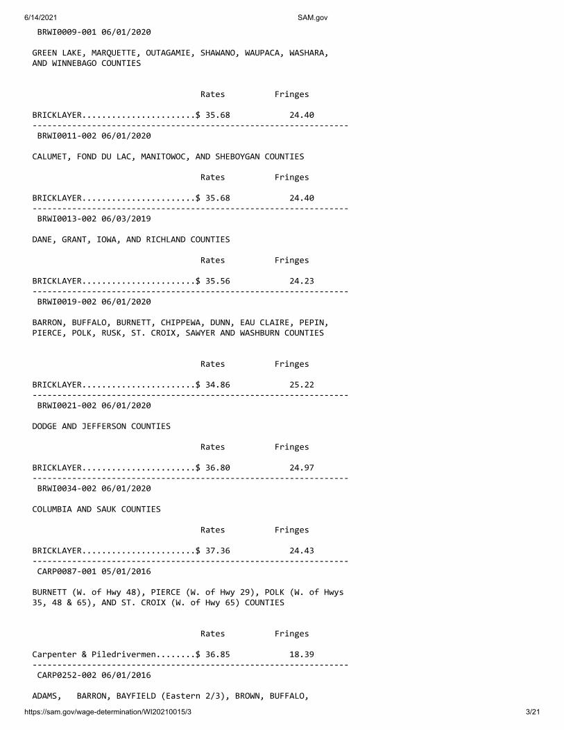
6/14/2021 SAM.gov
https://sam.gov/wage-determination/WI20210015/3 3/21
BRWI0009-001 06/01/2020
GREEN LAKE, MARQUETTE, OUTAGAMIE, SHAWANO, WAUPACA, WASHARA, AND WINNEBAGO COUNTIES
Rates Fringes
BRICKLAYER.......................$ 35.68 24.40 ---------------------------------------------------------------- BRWI0011-002 06/01/2020
CALUMET, FOND DU LAC, MANITOWOC, AND SHEBOYGAN COUNTIES
Rates Fringes
BRICKLAYER.......................$ 35.68 24.40 ---------------------------------------------------------------- BRWI0013-002 06/03/2019
DANE, GRANT, IOWA, AND RICHLAND COUNTIES
Rates Fringes
BRICKLAYER.......................$ 35.56 24.23 ---------------------------------------------------------------- BRWI0019-002 06/01/2020
BARRON, BUFFALO, BURNETT, CHIPPEWA, DUNN, EAU CLAIRE, PEPIN, PIERCE, POLK, RUSK, ST. CROIX, SAWYER AND WASHBURN COUNTIES
Rates Fringes
BRICKLAYER.......................$ 34.86 25.22 ---------------------------------------------------------------- BRWI0021-002 06/01/2020
DODGE AND JEFFERSON COUNTIES
Rates Fringes
BRICKLAYER.......................$ 36.80 24.97 ---------------------------------------------------------------- BRWI0034-002 06/01/2020
COLUMBIA AND SAUK COUNTIES
Rates Fringes
BRICKLAYER.......................$ 37.36 24.43 ---------------------------------------------------------------- CARP0087-001 05/01/2016
BURNETT (W. of Hwy 48), PIERCE (W. of Hwy 29), POLK (W. of Hwys 35, 48 & 65), AND ST. CROIX (W. of Hwy 65) COUNTIES
Rates Fringes
Carpenter & Piledrivermen........$ 36.85 18.39 ---------------------------------------------------------------- CARP0252-002 06/01/2016
ADAMS, BARRON, BAYFIELD (Eastern 2/3), BROWN, BUFFALO,

6/14/2021 SAM.gov
https://sam.gov/wage-determination/WI20210015/3 4/21
BURNETT (E. of Hwy 48), CALUMET, CHIPPEWA, CLARK, COLUMBIA, CRAWFORD, DANE, DODGE, DOOR, DUNN, EAU CLAIRE, FLORENCE (except area bordering Michigan State Line), FOND DU LAC, FOREST, GRANT, GREEN, GREEN LAKE, IOWA, IRON, JACKSON, JEFFERSON, JUNEAU, KEWAUNEE, LA CROSSE, LAFAYETTE, LANGLADE, LINCOLN, MANITOWOC, MARATHON, MARINETTE (except N.E. corner), MARQUETTE, MENOMINEE, MONROE, OCONTO, ONEIDA, OUTAGAMIE, PEPIN, PIERCE (E. of Hwys 29 & 65), POLK (E. of Hwys 35, 48 & 65), PORTAGE, PRICE, RICHLAND, ROCK, RUSK, SAUK, SAWYER, SHAWANO, SHEBOYGAN, ST CROIX (E. of Hwy 65), TAYLOR, TREMPEALEAU, VERNON, VILAS, WALWORTH, WASHBURN, WAUPACA, WAUSHARA, WINNEBAGO, AND WOOD COUNTIES
Rates Fringes
CARPENTER CARPENTER...................$ 33.56 18.00 MILLWRIGHT..................$ 35.08 18.35 PILEDRIVER..................$ 34.12 18.00 ---------------------------------------------------------------- CARP0252-010 06/01/2016
ASHLAND COUNTY
Rates Fringes
Carpenters Carpenter...................$ 33.56 18.00 Millwright..................$ 35.08 18.35 Pile Driver.................$ 34.12 18.00 ---------------------------------------------------------------- CARP0264-003 06/01/2016
KENOSHA, MILWAUKEE, OZAUKEE, RACINE, WAUKESHA, AND WASHINGTON COUNTIES
Rates Fringes
CARPENTER........................$ 35.78 22.11 ---------------------------------------------------------------- CARP0361-004 05/01/2018
BAYFIELD (West of Hwy 63) AND DOUGLAS COUNTIES
Rates Fringes
CARPENTER........................$ 36.15 20.43 ---------------------------------------------------------------- CARP2337-001 06/01/2016
ZONE A: MILWAUKEE, OZAUKEE, WAUKESHA AND WASHINGTON
ZONE B: KENOSHA & RACINE
Rates Fringes
PILEDRIVERMAN Zone A......................$ 31.03 22.69 Zone B......................$ 31.03 22.69 ---------------------------------------------------------------- CARP2337-003 06/01/2019

6/14/2021 SAM.gov
https://sam.gov/wage-determination/WI20210015/3 5/21
Rates Fringes
MILLWRIGHT Zone A......................$ 33.58 21.53 Zone B......................$ 33.58 21.53
ZONE DEFINITIONS
ZONE A: MILWAUKEE, OZAUKEE, WAUKESHA AND WASHINGTON COUNTIES
ZONE B: KENOSHA & RACINE COUNTIES
---------------------------------------------------------------- ELEC0014-002 06/14/2020
ASHLAND, BARRON, BAYFIELD, BUFFALO, BURNETT, CHIPPEWA, CLARK (except Maryville, Colby, Unity, Sherman, Fremont, Lynn & Sherwood), CRAWFORD, DUNN, EAU CLAIRE, GRANT, IRON, JACKSON, LA CROSSE, MONROE, PEPIN, PIERCE, POLK, PRICE, RICHLAND, RUSK, ST CROIX, SAWYER, TAYLOR, TREMPEALEAU, VERNON, AND WASHBURN COUNTIES
Rates Fringes
Electricians:....................$ 35.98 20.98 ---------------------------------------------------------------- ELEC0014-007 07/05/2020
REMAINING COUNTIES
Rates Fringes
Teledata System Installer Installer/Technician........$ 27.75 15.14
Low voltage construction, installation, maintenance and removal of teledata facilities (voice, data, and video) including outside plant, telephone and data inside wire, interconnect, terminal equipment, central offices, PABX, fiber optic cable and equipment, micro waves, V-SAT, bypass, CATV, WAN (wide area networks), LAN (local area networks), and ISDN (integrated systems digital network).
---------------------------------------------------------------- ELEC0127-002 06/01/2020
KENOSHA COUNTY
Rates Fringes
Electricians:....................$ 41.62 30%+12.70 ---------------------------------------------------------------- ELEC0158-002 06/01/2020
BROWN, DOOR, KEWAUNEE, MANITOWOC (except Schleswig), MARINETTE(Wausuakee and area South thereof), OCONTO, MENOMINEE (East of a ine 6 miles West of the West boundary of Oconto County), SHAWANO (Except Area North of Townships of Aniwa and Hutchins) COUNTIES
Rates Fringes
ELECTRICIAN......................$ 34.77 29.75%+10.26

6/14/2021 SAM.gov
https://sam.gov/wage-determination/WI20210015/3 6/21
---------------------------------------------------------------- ELEC0159-003 08/02/2020
COLUMBIA, DANE, DODGE (Area West of Hwy 26, except Chester and Emmet Townships), GREEN, LAKE (except Townships of Berlin, Seneca, and St. Marie), IOWA, MARQUETTE (except Townships of Neshkoka, Crystal Lake, Newton, and Springfield), and SAUK COUNTIES
Rates Fringes
ELECTRICIAN......................$ 41.86 22.67 ---------------------------------------------------------------- ELEC0219-004 06/01/2019
FLORENCE COUNTY (Townships of Aurora, Commonwealth, Fern, Florence and Homestead) AND MARINETTE COUNTY (Township of Niagara)
Rates Fringes
Electricians: Electrical contracts over $180,000....................$ 33.94 21.80 Electrical contracts under $180,000....................$ 31.75 21.73 ---------------------------------------------------------------- ELEC0242-005 05/31/2020
DOUGLAS COUNTY
Rates Fringes
Electricians:....................$ 39.77 28.11 ---------------------------------------------------------------- ELEC0388-002 06/01/2020
ADAMS, CLARK (Colby, Freemont, Lynn, Mayville, Sherman, Sherwood, Unity), FOREST, JUNEAU, LANGLADE, LINCOLN, MARATHON, MARINETTE (Beecher, Dunbar, Goodman & Pembine), MENOMINEE (Area West of a line 6 miles West of the West boundary of Oconto County), ONEIDA, PORTAGE, SHAWANO (Aniwa and Hutchins), VILAS AND WOOD COUNTIES
Rates Fringes
Electricians:....................$ 34.85 26%+11.20 ---------------------------------------------------------------- ELEC0430-002 02/02/2021
RACINE COUNTY (Except Burlington Township)
Rates Fringes
Electricians:....................$ 41.859 22.871 ---------------------------------------------------------------- ELEC0494-005 06/01/2020
MILWAUKEE, OZAUKEE, WASHINGTON, AND WAUKESHA COUNTIES
Rates Fringes

6/14/2021 SAM.gov
https://sam.gov/wage-determination/WI20210015/3 7/21
Electricians:....................$ 42.84 25.54 ---------------------------------------------------------------- ELEC0494-006 06/01/2020
CALUMET (Township of New Holstein), DODGE (East of Hwy 26 including Chester Township), FOND DU LAC, MANITOWOC (Schleswig), and SHEBOYGAN COUNTIES
Rates Fringes
Electricians:....................$ 36.32 22.51 ---------------------------------------------------------------- ELEC0494-013 06/07/2020
DODGE (East of Hwy 26 including Chester Twp, excluding Emmet Twp), FOND DU LAC (Except Waupuin), MILWAUKEE, OZAUKEE, MANITOWOC (Schleswig), WASHINGTON, AND WAUKESHA COUNTIES
Rates Fringes
Sound & Communications Installer...................$ 21.46 18.52 Technician..................$ 31.34 20.00
Installation, testing, maintenance, operation and servicing of all sound, intercom, telephone interconnect, closed circuit TV systems, radio systems, background music systems, language laboratories, electronic carillion, antenna distribution systems, clock and program systems and low-voltage systems such as visual nurse call, audio/visual nurse call systems, doctors entrance register systems. Includes all wire and cable carrying audio, visual, data, light and radio frequency signals. Includes the installation of conduit, wiremold, or raceways in existing structures that have been occupied for six months or more where required for the protection of the wire or cable, but does not mean a complete conduit or raceway system. work covered does not include the installation of conduit, wiremold or any raceways in any new construction, or the installation of power supply outlets by means of which external electric power is supplied to any of the foregoing equipment or products
---------------------------------------------------------------- ELEC0577-003 06/01/2020
CALUMET (except Township of New Holstein), GREEN LAKE (N. part including Townships of Berlin, St Marie, and Seneca), MARQUETTE (N. part including Townships of Crystal Lake, Neshkoro, Newton, and Springfield), OUTAGAMIE, WAUPACA, WAUSHARA, AND WINNEBAGO COUNTIES
Rates Fringes
Electricians:....................$ 34.23 29.50%+10.00 ---------------------------------------------------------------- ELEC0890-003 06/01/2020
DODGE (Emmet Township only), GREEN, JEFFERSON, LAFAYETTE, RACINE (Burlington Township), ROCK AND WALWORTH COUNTIES

6/14/2021 SAM.gov
https://sam.gov/wage-determination/WI20210015/3 8/21
Rates Fringes
Electricians:....................$ 37.41 25.95%+11.11 ---------------------------------------------------------------- ELEC0953-001 06/02/2019
Rates Fringes
Line Construction: (1) Lineman.................$ 47.53 21.43 (2) Heavy Equipment Operator....................$ 42.78 19.80 (3) Equipment Operator......$ 38.02 18.40 (4) Heavy Groundman Driver..$ 33.27 16.88 (5) Light Groundman Driver..$ 30.89 16.11 (6) Groundsman..............$ 26.14 14.60 ---------------------------------------------------------------- ENGI0139-001 06/01/2020
KENOSHA, MILWAUKEE, OZAUKEE, RACINE, WASHINGTON, AND WAUKESHA COUNTIES
Rates Fringes
Power Equipment Operator Group 1.....................$ 47.66 23.15 Group 2.....................$ 47.16 23.15 Group 3.....................$ 46.66 23.15 Group 4.....................$ 45.97 23.15 Group 5.....................$ 42.39 23.15 Group 6.....................$ 37.24 23.15
HAZARDOUS WASTE PREMIUMS: EPA Level ""A"" Protection: $3.00 per hour EPA Level ""B"" Protection: $2.00 per hour EPA Level ""C"" Protection: $1.00 per hour
POWER EQUIPMENT OPERATORS CLASSIFICATIONS
GROUP 1: Cranes, Tower Cranes, Pedestal Tower Cranes and Derricks with or w/o attachments with a lifting capacity of over 100 tons; or Cranes, Tower Cranes, Pedestal Tower Cranes and Derricks with boom, leads, and/or jib lengths measuring 176 feet or longer; Self-Erecting Tower Cranes over 4000 lbs lifting capacity; All Cranes with Boom Dollies; Boring Machines (directional); Master Mechanic. $0.50 additional per hour per 100 tons or 100 ft of boom over 200 ft or lifting capacity of crane over 200 tons to a maximum of 300 tons or 300 ft. Thereafter an increase of $0.01 per ft or ton, whichever is greater.
GROUP 2: Cranes, Tower Cranes, Pedestal Tower Cranes and Derricks with or without attachments with a lifting capacity of 100 tons or less; or Cranes, Tower Cranes Portable Tower Cranes, Pedestal Tower Cranes and Derricks with boom, leadsand/or jib lengths measuring 175 feet or less; Backhoes (excavators) 130,000 lbs and over; Caisson Rigs; Pile Drivers; Boring Machines (vertical or horizontal), Versi-Lift, Tri-Lift, Gantry 20,000 lbs & over.
GROUP 3: Backhoe (excavator) under 130,000 lbs;Self-erecting Tower Crane 4000 lbs & under lifting capacity;Traveling Crane (bridge type); Skid Rigs; Dredge Operator; Mechanic; Concrete Paver (over 27E); Concrete Spreader and

6/14/2021 SAM.gov
https://sam.gov/wage-determination/WI20210015/3 9/21
Distributor; Forklift/ Telehandler (machinery- moving / steel erection); Hydro Blaster, 10,000 psi and over
GROUP 4: Material Hoists; Stack Hoists; Hydraulic Backhoe (tractor or truck mounted); Hydraulic Crane, 5 tons or under (tractor or truck mounted); Hoist (tuggers 5 tons & over); Hydro-Excavators/Daylighters; Concrete Pumps Rotec type Conveyors; Tractor/Bulldozer/End Loader (over 40 hp); Motor Patrol; Scraper Operator; Sideboom; Straddle Carrier; Welder; Bituminous Plant and Paver Operator; Roller over 5 tons; Rail Leveling Machine (Railroad); Tie Placer; Tie Extractor; Tie Tamper; Stone Leveler; Rotary Drill Operator and Blaster; Percussion Drill Operator; Air Track Drill and/or Hammers; Gantrys (under 20,000 lbs); Tencher (wheel type or chain type having 8 inch or larger bucket); Milling Machine; Off-Road Material Haulers.
GROUP 5: Backfiller; Concrete Auto Breaker (large); Concrete Finishing Machines (road type); Rubber Tired Roller; Concrete Batch Hopper; Concrete Conveyor Systems; Grout Pumps; Concrete Mixers (14S or over); Screw Type Pumps and Gypsum Pumps; Tractor, Bulldozer, End Loader (under 40 hp); Trencher (chain type, bucket under 8 inch); Industrial Locomotives; Rollers under 5 tons; Stump Grinder/Chipper (Large); Timber Equipment; Firemen (pile drivers and derricks); Personnel Hoist, Telehandler over 8000 lbs; Robotic Tool Carrier with or without attachments
GROUP 6: Tampers - Compactors (riding type); Assistant Engineer; A-Frames and Winch Trucks; Concrete Auto Breaker; Hydrohammers (small); Brooms and Sweepers; Hoist (tuggers under 5 tons); Boats (Tug, Safety, Work Barges, Launch); Shouldering Machine Operator; Prestress Machines; Screed Operator; Stone Crushers and Screening Plants; Screed Operators (milling machine), Farm or Industrial Tractor Mounted Equipment; Post Hole Digger; Fireman (asphalt plants); Air Compressors over 400 CFM; Generators, over 150 KW; Augers (vertical and horizontal); Air, Electric, Hydraulic Jacks (slipform); Skid Steer Loaders (with or without attachments); Boiler Operators (temporary heat); Refrigeration Plant/Freeze Machines; Power Pack Vibratory/Ultra Sound Drivers and Extractors; Welding Machines; Heaters (mechanical); Pumps; Winches (small electric); Oiler and Greaser; Rotary Drill Tender; Conveyor; Forklifts/Telehandler 8000 lbs & under; Elevators: Automatic Hoists; Pumps (well points); Combination Small Equipment Operators
---------------------------------------------------------------- ENGI0139-003 06/01/2020
REMAINING COUNTIES
Rates Fringes
Power Equipment Operator Group 1.....................$ 42.92 23.15 Group 2.....................$ 41.67 23.15 Group 3.....................$ 39.97 23.15 Group 4.....................$ 39.44 23.15 Group 5.....................$ 37.37 23.15 Group 6.....................$ 35.84 23.15
HAZARDOUS WASTE PREMIUMS: EPA Level ""A"" Protection: $3.00 per hour

6/14/2021 SAM.gov
https://sam.gov/wage-determination/WI20210015/3 10/21
EPA Level ""B"" Protection: $2.00 per hour EPA Level ""C"" Protection: $1.00 per hour
POWER EQUIPMENT OPERATORS CLASSIFICATIONS
GROUP 1: Cranes, Tower Cranes and Derricks with or without attachments with a lifting capacity of over 100 tons; Cranes, Tower Cranes, and Derricks with boom, leads and/or jib lengths 176 ft or longer.
GROUP 2: Backhoes (Excavators) weighing 130,00 lbs and over; Cranes, Tower Cranes and Derricks with or without attachments with a lifting capacity of 100 tons or less; Cranes, Tower Cranes, and Derricks with boom, leads, and/or jib lengths 175 ft or less; Caisson Rigs; Pile Driver
GROUP 3: Backhoes (Excavators) weighing under 130,000 lbs; Travelling Crane (bridge type); Milling Machine; Concrete Paver over 27 E; Concrete Spreader and Distributor; Concrete Laser Screed; Concrete Grinder and Planing Machine; Slipform Curb and Gutter Machine; Boring Machine (Directional); Dredge Operator; Skid Rigs; over 46 meter Concrete Pump.
GROUP 4: Hydraulic Backhoe (tractor or truck mounted); Hydraulic Crane, 10 tons or less; Tractor, Bulldozer, or End Loader (over 40 hp); Motor Patrol; Scraper Operator; Bituminous Plant and Paver Operator; Screed-Milling Machine; Roller over 5 tons; Concrete pumps 46 meter and under; Grout Pumps; Rotec type machine; Hydro Blaster, 10,000 psi and over; Rotary Drill Operator; Percussion Drilling Machine; Air Track Drill with or without integral hammer; Blaster; Boring Machine (vertical or horizontal); Side Boom; Trencher, wheel type or chain type having 8 inch or larger bucket; Rail Leveling Machine (Railroad); Tie Placer; Tie Extractor; Tie Tamper; Stone Leveler; Straddle Carrier; Material Hoists; Stack Hoist; Man Hoists; Mechanic and Welder; Off Road Material Haulers.
GROUP 5: Tractor, Bulldozer, or Endloader (under 40 hp); Tampers -Compactors, riding type; Stump Chipper, large; Roller, Rubber Tire; Backfiller; Trencher, chain type (bucket under 8 inch); Concrete Auto Breaker, large; Concrete Finishing Machine (road type); Concrete Batch Hopper; Concrete Conveyor Systems; Concrete Mixers, 14S or over; Pumps, Screw Type and Gypsum); Hydrohammers, small; Brooms and Sweeeprs; Lift Slab Machine; Roller under 5 tons; Industrial Locomotives; Fireman (Pile Drivers and Derricks); Pumps (well points); Hoists, automatic; A-Frames and Winch Trucks; Hoists (tuggers); Boats (Tug, Safety, Work Barges and Launches); Assistant Engineer
GROUP 6: Shouldering Machine Operator; Farm or Industrial Tractor mounted equipment; Post Hole Digger; Auger (vertical and horizontal); Skid Steer Loader with or without attachments; Robotic Tool Carrier with or without attachments; Power Pack Vibratory/Ultra Sound Driver and Extractor; Fireman (Asphalt Plants); Screed Operator; Stone Crushers and Screening Plants; Air, Electric, Hydraulic Jacks (Slip Form); Prestress Machines; Air Compressor, 400 CFM or over; Refrigeration Plant/Freese Machine; Boiler Operators (temporary heat); Forklifts; Welding Machines; Generators; Pumps over 3""; Heaters, Mechanical; Combination small equipment operator; Winches, small electric; Oiler; Greaser; Rotary Drill Tender; Conveyor; Elevator Operator

6/14/2021 SAM.gov
https://sam.gov/wage-determination/WI20210015/3 11/21
---------------------------------------------------------------- IRON0008-002 06/01/2020
BROWN, CALUMET, DOOR, FOND DU LAC, KEWAUNEE, MANITOWOC, MARINETTE, OCONTO, OUTAGAMI, SHAWANO, SHEBOYGAN, AND WINNEBAGO COUNTIES:
Rates Fringes
IRONWORKER.......................$ 37.31 27.62
Paid Holidays: New Year's Day, Memorial Day, July 4th, Labor Day, Thanksgiving Day & Christmas Day.
---------------------------------------------------------------- IRON0008-003 06/01/2020
KENOSHA, MILWAUKEE, OZAUKEE, RACINE, WALWORTH (N.E. 2/3), WASHINGTON, AND WAUKESHA COUNTIES
Rates Fringes
IRONWORKER.......................$ 39.11 27.87
Paid Holidays: New Year's Day, Memorial Day, July 4th, Labor Day, Thanksgiving Day & Christmas Day.
---------------------------------------------------------------- IRON0383-001 06/01/2020
ADAMS, COLUMBIA, CRAWFORD, DANE, DODGE, FLORENCE, FOREST, GRANT, GREENE, (Excluding S.E. tip), GREEN LAKE, IOWA, JEFFERSON, JUNEAU, LA CROSSE, LAFAYETTE, LANGLADE, MARATHON, MARQUETTE, MENOMINEE, MONROE, PORTAGE, RICHLAND, ROCK (Northern area, vicinity of Edgerton and Milton), SAUK, VERNON, WAUPACA, WAUSHARA, AND WOOD COUNTIES
Rates Fringes
IRONWORKER.......................$ 37.10 27.06 ---------------------------------------------------------------- IRON0512-008 06/03/2019
BARRON, BUFFALO, CHIPPEWA, CLARK, DUNN, EAU CLAIRE, JACKSON, PEPIN, PIERCE, POLK, RUSK, ST CROIX, TAYLOR, AND TREMPEALEAU COUNTIES
Rates Fringes
IRONWORKER.......................$ 37.60 29.40 ---------------------------------------------------------------- * IRON0512-021 05/03/2021
ASHLAND, BAYFIELD, BURNETT, DOUGLAS, IRON, LINCOLN, ONEIDA, PRICE, SAWYER, VILAS AND WASHBURN COUNTIES
Rates Fringes
IRONWORKER.......................$ 35.09 31.80

6/14/2021 SAM.gov
https://sam.gov/wage-determination/WI20210015/3 12/21
---------------------------------------------------------------- LABO0113-002 06/01/2020
MILWAUKEE AND WAUKESHA COUNTIES
Rates Fringes
LABORER Group 1.....................$ 30.05 22.26 Group 2.....................$ 30.20 22.26 Group 3.....................$ 30.40 22.26 Group 4.....................$ 30.55 22.26 Group 5.....................$ 30.70 22.26 Group 6.....................$ 26.54 22.26
LABORERS CLASSIFICATIONS
GROUP 1: General Laborer; Tree Trimmer; Conduit Layer; Demolition and Wrecking Laborer; Guard Rail, Fence, and Bridge Builder; Landscaper; Multiplate Culvert Assembler; Stone Handler; Bituminous Worker (Shoveler, Loader, and Utility Man); Batch Truck Dumper or Cement Handler; Bituminous Worker (Dumper, Ironer, Smoother, and Tamper); Concrete Handler
GROUP 2: Air Tool Operator; Joint Sawer and Filler (Pavement); Vibrator or Tamper Operator (Mechanical Hand Operated); Chain Saw Operator; Demolition Burning Torch Laborer
GROUP 3: Bituminous Worker (Raker and Luteman); Formsetter (Curb, Sidewalk, and Pavement); Strike Off Man
GROUP 4: Line and Grade Specialist
GROUP 5: Blaster and Powderman
GROUP 6: Flagperson; traffic control person
---------------------------------------------------------------- LABO0113-003 06/01/2020
OZAUKEE AND WASHINGTON COUNTIES
Rates Fringes
LABORER Group 1.....................$ 29.30 22.26 Group 2.....................$ 29.40 22.26 Group 3.....................$ 29.45 22.26 Group 4.....................$ 29.65 22.26 Group 5.....................$ 29.50 22.26 Group 6.....................$ 26.39 22.26
LABORERS CLASSIFICATIONS
GROUP 1: General Laborer; Tree Trimmer; Conduit Layer; Demolition and Wrecking Laborer; Guard Rail, Fence, and Bridge Builder; Landscaper; Multiplate Culvert Assembler; Stone Handler; Bituminous Worker (Shoveler, Loader, and Utility Man); Batch Truck Dumper or Cement Handler; Bituminous Worker (Dumper, Ironer, Smoother, and Tamper); Concrete Handler
GROUP 2: Air Tool Operator; Joint Sawer and Filler

6/14/2021 SAM.gov
https://sam.gov/wage-determination/WI20210015/3 13/21
(Pavement); Vibrator or Tamper Operator (Mechanical Hand Operated);
GROUP 3: Bituminous Worker (Raker and Luteman); Formsetter (Curb, Sidewalk, and Pavement); Strike Off Man
GROUP 4: Line and Grade Specialist
GROUP 5: Blaster; powderman
GROUP 6: Flagperson and Traffic Control Person
---------------------------------------------------------------- LABO0113-011 06/01/2020
KENOSHA AND RACINE COUNTIES
Rates Fringes
LABORER Group 1.....................$ 29.11 22.26 Group 2.....................$ 29.26 22.26 Group 3.....................$ 29.46 22.26 Group 4.....................$ 29.43 22.26 Group 5.....................$ 29.76 22.26 Group 6.....................$ 26.25 22.26
LABORERS CLASSIFICATIONS:
GROUP 1: General laborer; Tree Trimmer; Conduit Layer; Demolition and Wrecking Laborer; Guard Rail, Fence, and Bridge Builder; Landscaper; Multiplate Culvert Assembler; Stone Handler; Bituminous Worker (Shoveler, Loader, and Utility Man); Batch Truck Dumper or Cement Handler; Bituminous worker (Dumper, Ironer, Smoother, and Tamper); Concrete Handler
GROUP 2: Air Tool Operator; Joint Sawer and Filler (Pavement); Vibrator or Tamper Operator (Mechanical Hand Operated); Chain Saw Operator; Demolition Burning Torch Laborer
GROUP 3: Bituminous Worker (Raker and Luteman); Formsetter (Curb, Sidewalk, and Pavement); Strike Off Man
GROUP 4: Line and Grade Specialist
GROUP 5: Blaster and Powderman
GROUP 6: Flagman; traffic control person
---------------------------------------------------------------- LABO0140-002 06/01/2020
ADAMS, ASHLAND, BARRON, BAYFIELD, BROWN, BUFFALO, BURNETT, CALUMET, CHIPPEWA, CLARK, COLUMBIA, CRAWFORD, DODGE, DOOR, DOUGLAS, DUNN, EAU CLAIRE, FLORENCE, FOND DU LAC, FOREST, GRANT, GREEN, GREEN LAKE, IRON, JACKSON, JUNEAU, IOWA, JEFFERSON, KEWAUNEE, LA CROSSE, LAFAYETTE, LANGLADE, LINCOLN, MANITOWOC, MARATHON, MARINETTE, MARQUETTE, MENOMINEE, MONROE, OCONTO, ONEIDA, OUTAGAMIE, PEPIN, PIERCE, POLK, PORTAGE, PRICE, RICHLAND, ROCK, RUSK, SAUK, SAWYER, SHAWANO, SHEBOYGAN, ST. CROIX, TAYLOR, TREMPEALEAU, VERNON, VILLAS, WALWORTH, WASHBURN, WAUPACA, WAUSHARA, WINNEBAGO, AND WOOD COUNTIES

6/14/2021 SAM.gov
https://sam.gov/wage-determination/WI20210015/3 14/21
Rates Fringes
LABORER Group 1.....................$ 33.72 17.95 Group 2.....................$ 33.82 17.95 Group 3.....................$ 33.87 17.95 Group 4.....................$ 34.07 17.95 Group 5.....................$ 33.92 17.95 Group 6.....................$ 30.35 17.95
LABORER CLASSIFICATIONS
GROUP 1: General Laborer; Tree Trimmer; Conduit Layer; Demolition and Wrecking Laborer; Guard Rail, Fence, and Bridge Builder; Landscaper; Multiplate Culvert Assembler; Stone Handler; Bitminous Worker (Shoveler, Loader, and Utility Man); Batch Truck Dumper or Cement Handler; Bituminous Worker (Dumper, Ironer, Smoother and Tamper); Concrete Handler
GROUP 2: Air Tool Operator; Joint Sawer and Filler (Pavement); Vibrator or Tamper Operator (Mechanical Hand Operated); Chain Saw Operator, Demolition Burning Torch Laborer
GROUP 3: Bituminous Worker (Raker and Luteman); Formsetter (Curb, Sidewalk and Pavement); Strike Off Man
GROUP 4: Line and Grade Secialist
GROUP 5: Blaster; powderman
GROUP 6: Flagperson; Traffic Control
---------------------------------------------------------------- LABO0464-003 06/01/2020
DANE COUNTY
Rates Fringes
LABORER Group 1.....................$ 34.00 17.95 Group 2.....................$ 34.10 17.95 Group 3.....................$ 34.15 17.95 Group 4.....................$ 34.35 17.95 Group 5.....................$ 34.20 17.95 Group 6.....................$ 30.35 17.95
LABORERS CLASSIFICATIONS:
GROUP 1: General Laborer; Tree Trimmer; Conduit Layer; Demolition and Wrecking Laborer; Guard Rail, Fence, and Bridge Builder; Landscaper; Multiplate Culvert Assembler; Stone Handler; Bituminous Worker (Shoveler, Loader, and Utility Man); Batch Truck Dumper or Cement Handler; Bituminious Worker (Dumper, Ironer, Smoother, and Tamper); Concrete Handler
GROUP 2: Air Tool Operator; Joint Sawer and Filler (Pavement); Vibrator or Tamper Operator (Mechanical Hand Operated); Chain Saw Operator; Demolition Burning Torch Laborer

6/14/2021 SAM.gov
https://sam.gov/wage-determination/WI20210015/3 15/21
GROUP 3: Bituminous Worker (Raker and Luteman); Formsetter (Curb, Sidewalk, and Pavement); Strike Off Man
GROUP 4: Line and Grade Specialist
GROUP 5: Blaster; Powderman
GROUP 6: Flagperson and Traffic Control Person
---------------------------------------------------------------- PAIN0106-008 05/01/2017
ASHLAND, BAYFIELD, BURNETT, AND DOUGLAS COUNTIES
Rates Fringes
Painters: New: Brush, Roller..............$ 30.33 17.27 Spray, Sandblast, Steel....$ 30.93 17.27 Repaint: Brush, Roller..............$ 28.83 17.27 Spray, Sandblast, Steel....$ 29.43 17.27 ---------------------------------------------------------------- PAIN0108-002 06/01/2019
RACINE COUNTY
Rates Fringes
Painters: Brush, Roller...............$ 36.08 20.36 Spray & Sandblast...........$ 37.08 20.36 ---------------------------------------------------------------- PAIN0259-002 05/01/2008
BARRON, CHIPPEWA, DUNN, EAU CLAIRE, PEPIN, PIERCE, POLK, RUSK, SAWYER, ST. CROIX, AND WASHBURN COUNTIES
Rates Fringes
PAINTER..........................$ 24.11 12.15 ---------------------------------------------------------------- PAIN0259-004 05/01/2015
BUFFALO, CRAWFORD, JACKSON, LA CROSSE, MONROE, TREMPEALEAU, AND VERNON COUNTIES
Rates Fringes
PAINTER..........................$ 22.03 12.45 ---------------------------------------------------------------- PAIN0781-002 06/01/2019
JEFFERSON, MILWAUKEE, OZAUKEE, WASHINGTON, AND WAUKESHA COUNTIES
Rates Fringes
Painters: Bridge......................$ 33.30 23.86 Brush.......................$ 32.95 23.86 Spray & Sandblast...........$ 33.70 23.86 ----------------------------------------------------------------

6/14/2021 SAM.gov
https://sam.gov/wage-determination/WI20210015/3 16/21
PAIN0802-002 06/01/2019
COLUMBIA, DANE, DODGE, GRANT, GREEN, IOWA, LAFAYETTE, RICHLAND, ROCK, AND SAUK COUNTIES
Rates Fringes
PAINTER Brush.......................$ 30.93 18.44
PREMIUM PAY: Structural Steel, Spray, Bridges = $1.00 additional per hour.
---------------------------------------------------------------- PAIN0802-003 06/01/2019
ADAMS, BROWN, CALUMET, CLARK, DOOR, FOND DU LAC, FOREST, GREEN LAKE, IRON, JUNEAU, KEWAUNEE, LANGLADE, LINCOLN, MANITOWOC, MARATHON, MARINETTE, MARQUETTE, MENOMINEE, OCONTO, ONEIDA, OUTAGAMIE, PORTAGE, PRICE, SHAWANO, SHEBOYGAN, TAYLOR, VILAS, WAUSHARA, WAUPACA, WINNEBAGO, AND WOOD COUNTIES
Rates Fringes
PAINTER..........................$ 30.93 18.58 ---------------------------------------------------------------- PAIN0934-001 06/01/2017
KENOSHA AND WALWORTH COUNTIES
Rates Fringes
Painters: Brush.......................$ 33.74 18.95 Spray.......................$ 34.74 18.95 Structural Steel............$ 33.89 18.95 ---------------------------------------------------------------- PAIN1011-002 06/02/2019
FLORENCE COUNTY
Rates Fringes
Painters:........................$ 25.76 13.33 ---------------------------------------------------------------- PLAS0599-010 06/01/2017
Rates Fringes
CEMENT MASON/CONCRETE FINISHER Area 1......................$ 39.46 17.17 Area 2 (BAC)................$ 35.07 19.75 Area 3......................$ 35.61 19.40 Area 4......................$ 34.70 20.51 Area 5......................$ 36.27 18.73 Area 6......................$ 32.02 22.99
AREA DESCRIPTIONS
AREA 1: BAYFIELD, DOUGLAS, PRICE, SAWYER, AND WASHBURN COUNTIES

6/14/2021 SAM.gov
https://sam.gov/wage-determination/WI20210015/3 17/21
AREA 2: ADAMS, ASHLAND, BARRON, BROWN, BURNETT, CALUMET, CHIPPEWA, CLARK, COLUMBIA, DODGE, DOOR, DUNN, FLORENCE, FOND DU LAC, FOREST, GREEN LAKE, IRON, JEFFERSON, KEWAUNEE, LANGLADE, LINCOLN, MANITOWOC, MARATHON, MARINETTE, MARQUETTE, MENOMINEE, OCONTO, ONEIDA, OUTAGAMIE, POLK, PORTAGE, RUSK, ST CROIX, SAUK, SHAWANO, SHEBOYGAN, TAYLOR, VILAS, WALWORTH, WAUPACA, WAUSHARA, WINNEBAGO, AND WOOD COUNTIES
AREA 3: BUFFALO, CRAWFORD, EAU CLAIRE, JACKSON, JUNEAU, LA CROSSE MONROE, PEPIN, PIERCE, RICHLAND, TREMPEALEAU, AND VERNON COUNTIES
AREA 4: MILWAUKEE, OZAUKEE, WASHINGTON, AND WAUKESHA COUNTIES
AREA 5: DANE, GRANT, GREEN, IOWA, LAFAYETTE, AND ROCK COUNTIES
AREA 6: KENOSHA AND RACINE COUNTIES
---------------------------------------------------------------- PLUM0011-003 05/07/2018
ASHLAND, BAYFIELD, BURNETT, DOUGLAS, IRON, SAWYER, AND WASHBURN COUNTIES
Rates Fringes
PLUMBER..........................$ 40.63 20.72 ---------------------------------------------------------------- PLUM0075-002 06/01/2016
MILWAUKEE, OZAUKEE, WASHINGTON, AND WAUKESHA COUNTIES
Rates Fringes
PLUMBER..........................$ 40.27 21.47 ---------------------------------------------------------------- PLUM0075-004 06/01/2016
DODGE (Watertown), GREEN, JEFFERSON, LAFAYETTE, AND ROCK COUNTIES
Rates Fringes
PLUMBER..........................$ 40.52 21.47 ---------------------------------------------------------------- PLUM0075-009 06/01/2016
COLUMBIA, DANE, IOWA, MARQUETTE, RICHLAND AND SAUK COUNTIES
Rates Fringes
PLUMBER..........................$ 38.82 20.12 ---------------------------------------------------------------- PLUM0111-007 05/28/2018
MARINETTE COUNTY (Niagara only)
Rates Fringes
PLUMBER/PIPEFITTER...............$ 33.33 24.48

6/14/2021 SAM.gov
https://sam.gov/wage-determination/WI20210015/3 18/21
---------------------------------------------------------------- PLUM0118-002 06/01/2020
KENOSHA, RACINE, AND WALWORTH COUNTIES
Rates Fringes
Plumber and Steamfitter..........$ 43.95 24.35 ---------------------------------------------------------------- PLUM0400-003 06/04/2018
ADAMS,BROWN, CALUMET, DODGE (except Watertown), DOOR, FOND DU LAC, GREEN LAKE,KEWAUNEE, MANITOWOC, MARINETTE (except Niagara), MENOMINEE, OCONTO, OUTAGAMIE, SHAWANO, SHEBOYGAN, WAUPACA, WAUSHARA, AND WINNEBAGO COUNTIES
Rates Fringes
PLUMBER/PIPEFITTER...............$ 36.74 19.06 ---------------------------------------------------------------- PLUM0434-002 05/31/2020
BARON, BUFFALO, CHIPPEWA, CLARK, CRAWFORD, DUNN, EAU CLAIRE, FLORENCE, FOREST, GRANT, JACKSON, JUNEAU, LA CROSSE, LANGLADE, LINCOLN, MARATHON, MONROE, ONEIDA, PEPIN, PIERCE, POLK, PORTAGE, PRICE, RUSK, ST. CROIX, TAYLOR, TREMPEALEAU, VERNON, VILAS, AND WOOD COUNTIES
Rates Fringes
PIPEFITTER.......................$ 42.70 20.47 ---------------------------------------------------------------- PLUM0601-003 06/01/2020
DODGE (Watertown), GREEN, JEFFERSON, LAFAYETTE, MILWAUKEE, OZAUKEE, ROCK, WASHINGTON AND WAUKESHA COUNTIES
Rates Fringes
PIPEFITTER.......................$ 47.79 26.57 ---------------------------------------------------------------- PLUM0601-009 06/01/2020
COLUMBIA, DANE, IOWA, MARQUETTE, RICHLAND AND SAUK COUNTIES
Rates Fringes
PIPEFITTER.......................$ 49.53 24.82 ---------------------------------------------------------------- TEAM0039-002 06/01/2020
Rates Fringes
TRUCK DRIVER 1 & 2 Axle Trucks...........$ 31.07 22.94 3 or more axles; Euclids or Dumptor, Articulated Truck, Mechanic.............$ 31.22 22.94 ---------------------------------------------------------------- SUWI2011-001 11/16/2011
Rates Fringes

6/14/2021 SAM.gov
https://sam.gov/wage-determination/WI20210015/3 19/21
WELL DRILLER.....................$ 16.52 ----------------------------------------------------------------
WELDERS - Receive rate prescribed for craft performing operation to which welding is incidental.
================================================================ Note: Executive Order (EO) 13706, Establishing Paid Sick Leave for Federal Contractors applies to all contracts subject to the Davis-Bacon Act for which the contract is awarded (and any solicitation was issued) on or after January 1, 2017. If this contract is covered by the EO, the contractor must provide employees with 1 hour of paid sick leave for every 30 hours they work, up to 56 hours of paid sick leave each year. Employees must be permitted to use paid sick leave for their own illness, injury or other health-related needs, including preventive care; to assist a family member (or person who is like family to the employee) who is ill, injured, or has other health-related needs, including preventive care; or for reasons resulting from, or to assist a family member (or person who is like family to the employee) who is a victim of, domestic violence, sexual assault, or stalking. Additional information on contractor requirements and worker protections under the EO is available at www.dol.gov/whd/govcontracts.
Unlisted classifications needed for work not included within the scope of the classifications listed may be added after award only as provided in the labor standards contract clauses (29CFR 5.5 (a) (1) (ii)).
----------------------------------------------------------------
The body of each wage determination lists the classification and wage rates that have been found to be prevailing for the cited type(s) of construction in the area covered by the wage determination. The classifications are listed in alphabetical order of ""identifiers"" that indicate whether the particular rate is a union rate (current union negotiated rate for local), a survey rate (weighted average rate) or a union average rate (weighted union average rate).
Union Rate Identifiers
A four letter classification abbreviation identifier enclosed in dotted lines beginning with characters other than ""SU"" or ""UAVG"" denotes that the union classification and rate were prevailing for that classification in the survey. Example: PLUM0198-005 07/01/2014. PLUM is an abbreviation identifier of the union which prevailed in the survey for this classification, which in this example would be Plumbers. 0198 indicates the local union number or district council number where applicable, i.e., Plumbers Local 0198. The next number, 005 in the example, is an internal number used in processing the wage determination. 07/01/2014 is the effective date of the most current negotiated rate, which in this example is July 1, 2014.
Union prevailing wage rates are updated to reflect all rate changes in the collective bargaining agreement (CBA) governing this classification and rate.

6/14/2021 SAM.gov
https://sam.gov/wage-determination/WI20210015/3 20/21
Survey Rate Identifiers
Classifications listed under the ""SU"" identifier indicate that no one rate prevailed for this classification in the survey and the published rate is derived by computing a weighted average rate based on all the rates reported in the survey for that classification. As this weighted average rate includes all rates reported in the survey, it may include both union and non-union rates. Example: SULA2012-007 5/13/2014. SU indicates the rates are survey rates based on a weighted average calculation of rates and are not majority rates. LA indicates the State of Louisiana. 2012 is the year of survey on which these classifications and rates are based. The next number, 007 in the example, is an internal number used in producing the wage determination. 5/13/2014 indicates the survey completion date for the classifications and rates under that identifier.
Survey wage rates are not updated and remain in effect until a new survey is conducted.
Union Average Rate Identifiers
Classification(s) listed under the UAVG identifier indicate that no single majority rate prevailed for those classifications; however, 100% of the data reported for the classifications was union data. EXAMPLE: UAVG-OH-0010 08/29/2014. UAVG indicates that the rate is a weighted union average rate. OH indicates the state. The next number, 0010 in the example, is an internal number used in producing the wage determination. 08/29/2014 indicates the survey completion date for the classifications and rates under that identifier.
A UAVG rate will be updated once a year, usually in January of each year, to reflect a weighted average of the current negotiated/CBA rate of the union locals from which the rate is based.
----------------------------------------------------------------
WAGE DETERMINATION APPEALS PROCESS
1.) Has there been an initial decision in the matter? This can be:
* an existing published wage determination * a survey underlying a wage determination * a Wage and Hour Division letter setting forth a position on a wage determination matter * a conformance (additional classification and rate) ruling
On survey related matters, initial contact, including requests for summaries of surveys, should be with the Wage and Hour Regional Office for the area in which the survey was conducted because those Regional Offices have responsibility for the Davis-Bacon survey program. If the response from this initial contact is not satisfactory, then the process described in 2.) and 3.) should be followed.
With regard to any other matter not yet ripe for the formal process described here, initial contact should be with the Branch of Construction Wage Determinations. Write to:
Branch of Construction Wage Determinations

6/14/2021 SAM.gov
https://sam.gov/wage-determination/WI20210015/3 21/21
Wage and Hour Division U.S. Department of Labor 200 Constitution Avenue, N.W. Washington, DC 20210
2.) If the answer to the question in 1.) is yes, then an interested party (those affected by the action) can request review and reconsideration from the Wage and Hour Administrator (See 29 CFR Part 1.8 and 29 CFR Part 7). Write to:
Wage and Hour Administrator U.S. Department of Labor 200 Constitution Avenue, N.W. Washington, DC 20210
The request should be accompanied by a full statement of the interested party's position and by any information (wage payment data, project description, area practice material, etc.) that the requestor considers relevant to the issue.
3.) If the decision of the Administrator is not favorable, an interested party may appeal directly to the Administrative Review Board (formerly the Wage Appeals Board). Write to:
Administrative Review Board U.S. Department of Labor 200 Constitution Avenue, N.W. Washington, DC 20210
4.) All decisions by the Administrative Review Board are final.
================================================================
END OF GENERAL DECISION"

THIS PAGE INTENTIONALLY LEFT BLANK

6/14/2021 SAM.gov
https://sam.gov/wage-determination/WI20210010/4 1/17
"General Decision Number: WI20210010 05/14/2021
Superseded General Decision Number: WI20200010
State: Wisconsin
Construction Type: Highway
Counties: Wisconsin Statewide.
HIGHWAY, AIRPORT RUNWAY & TAXIWAY CONSTRUCTION PROJECTS (does not include bridges over navigable waters; tunnels; buildings in highway rest areas; and railroad construction)
Note: Under Executive Order (EO) 13658, an hourly minimum wage of $10.95 for calendar year 2021 applies to all contracts subject to the Davis-Bacon Act for which the contract is awarded (and any solicitation was issued) on or after January 1, 2015. If this contract is covered by the EO, the contractor must pay all workers in any classification listed on this wage determination at least $10.95 per hour (or the applicable wage rate listed on this wage determination, if it is higher) for all hours spent performing on the contract in calendar year 2021. If this contract is covered by the EO and a classification considered necessary for performance of work on the contract does not appear on this wage determination, the contractor must pay workers in that classification at least the wage rate determined through the conformance process set forth in 29 CFR 5.5(a)(1)(ii) (or the EO minimum wage rate,if it is higher than the conformed wage rate). The EO minimum wage rate will be adjusted annually. Please note that this EO applies to the above-mentioned types of contracts entered into by the federal government that are subject to the Davis-Bacon Act itself, but it does not apply to contracts subject only to the Davis-Bacon Related Acts, including those set forth at 29 CFR 5.1(a)(2)-(60). Additional information on contractor requirements and worker protections under the EO is available at www.dol.gov/whd/govcontracts.
Modification Number Publication Date 0 01/01/2021 1 03/12/2021 2 03/19/2021 3 04/09/2021 4 05/14/2021
BRWI0001-002 06/01/2020
CRAWFORD, JACKSON, JUNEAU, LA CROSSE, MONROE, TREMPEALEAU, AND VERNON COUNTIES
Rates Fringes
BRICKLAYER.......................$ 35.31 24.7 7 ---------------------------------------------------------------- BRWI0002-002 06/01/2020
ASHLAND, BAYFIELD, DOUGLAS, AND IRON COUNTIES
Rates Fringes
BRICKLAYER.......................$ 42.77 23.47
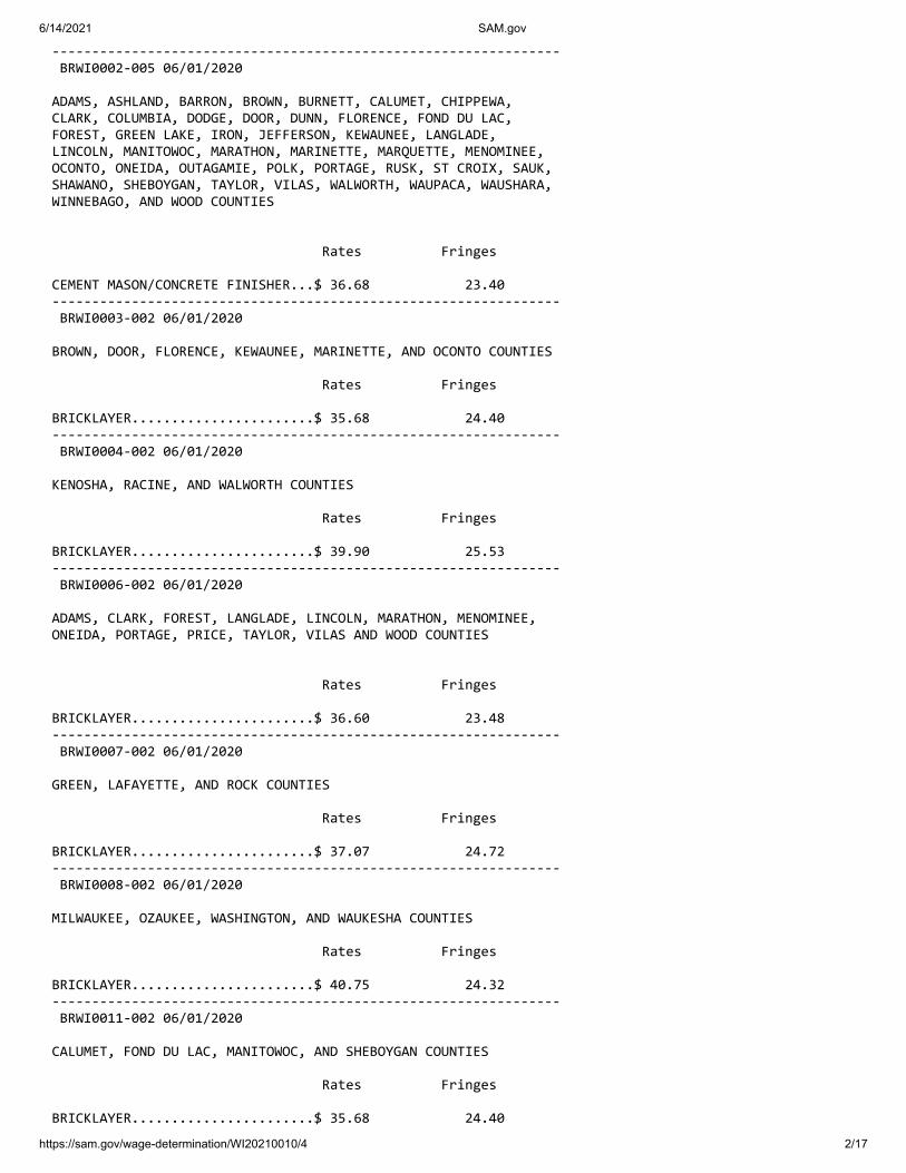
6/14/2021 SAM.gov
https://sam.gov/wage-determination/WI20210010/4 2/17
---------------------------------------------------------------- BRWI0002-005 06/01/2020
ADAMS, ASHLAND, BARRON, BROWN, BURNETT, CALUMET, CHIPPEWA, CLARK, COLUMBIA, DODGE, DOOR, DUNN, FLORENCE, FOND DU LAC, FOREST, GREEN LAKE, IRON, JEFFERSON, KEWAUNEE, LANGLADE, LINCOLN, MANITOWOC, MARATHON, MARINETTE, MARQUETTE, MENOMINEE, OCONTO, ONEIDA, OUTAGAMIE, POLK, PORTAGE, RUSK, ST CROIX, SAUK, SHAWANO, SHEBOYGAN, TAYLOR, VILAS, WALWORTH, WAUPACA, WAUSHARA, WINNEBAGO, AND WOOD COUNTIES
Rates Fringes
CEMENT MASON/CONCRETE FINISHER...$ 36.68 23.40 ---------------------------------------------------------------- BRWI0003-002 06/01/2020
BROWN, DOOR, FLORENCE, KEWAUNEE, MARINETTE, AND OCONTO COUNTIES
Rates Fringes
BRICKLAYER.......................$ 35.68 24.40 ---------------------------------------------------------------- BRWI0004-002 06/01/2020
KENOSHA, RACINE, AND WALWORTH COUNTIES
Rates Fringes
BRICKLAYER.......................$ 39.90 25.53 ---------------------------------------------------------------- BRWI0006-002 06/01/2020
ADAMS, CLARK, FOREST, LANGLADE, LINCOLN, MARATHON, MENOMINEE, ONEIDA, PORTAGE, PRICE, TAYLOR, VILAS AND WOOD COUNTIES
Rates Fringes
BRICKLAYER.......................$ 36.60 23.48 ---------------------------------------------------------------- BRWI0007-002 06/01/2020
GREEN, LAFAYETTE, AND ROCK COUNTIES
Rates Fringes
BRICKLAYER.......................$ 37.07 24.72 ---------------------------------------------------------------- BRWI0008-002 06/01/2020
MILWAUKEE, OZAUKEE, WASHINGTON, AND WAUKESHA COUNTIES
Rates Fringes
BRICKLAYER.......................$ 40.75 24.32 ---------------------------------------------------------------- BRWI0011-002 06/01/2020
CALUMET, FOND DU LAC, MANITOWOC, AND SHEBOYGAN COUNTIES
Rates Fringes
BRICKLAYER.......................$ 35.68 24.40

6/14/2021 SAM.gov
https://sam.gov/wage-determination/WI20210010/4 3/17
---------------------------------------------------------------- BRWI0019-002 06/01/2020
BARRON, BUFFALO, BURNETT, CHIPPEWA, DUNN, EAU CLAIRE, PEPIN, PIERCE, POLK, RUSK, ST. CROIX, SAWYER AND WASHBURN COUNTIES
Rates Fringes
BRICKLAYER.......................$ 34.86 25.22 ---------------------------------------------------------------- BRWI0034-002 06/01/2020
COLUMBIA AND SAUK COUNTIES
Rates Fringes
BRICKLAYER.......................$ 37.36 24.43 ---------------------------------------------------------------- CARP0087-001 05/01/2016
BURNETT (W. of Hwy 48), PIERCE (W. of Hwy 29), POLK (W. of Hwys 35, 48 & 65), AND ST. CROIX (W. of Hwy 65) COUNTIES
Rates Fringes
Carpenter & Piledrivermen........$ 36.85 18.39 ---------------------------------------------------------------- CARP0252-002 06/01/2016
ADAMS, BARRON, BAYFIELD (Eastern 2/3), BROWN, BUFFALO, BURNETT (E. of Hwy 48), CALUMET, CHIPPEWA, CLARK, COLUMBIA, CRAWFORD, DANE, DODGE, DOOR, DUNN, EAU CLAIRE, FLORENCE (except area bordering Michigan State Line), FOND DU LAC, FOREST, GRANT, GREEN, GREEN LAKE, IOWA, IRON, JACKSON, JEFFERSON, JUNEAU, KEWAUNEE, LA CROSSE, LAFAYETTE, LANGLADE, LINCOLN, MANITOWOC, MARATHON, MARINETTE (except N.E. corner), MARQUETTE, MENOMINEE, MONROE, OCONTO, ONEIDA, OUTAGAMIE, PEPIN, PIERCE (E. of Hwys 29 & 65), POLK (E. of Hwys 35, 48 & 65), PORTAGE, PRICE, RICHLAND, ROCK, RUSK, SAUK, SAWYER, SHAWANO, SHEBOYGAN, ST CROIX (E. of Hwy 65), TAYLOR, TREMPEALEAU, VERNON, VILAS, WALWORTH, WASHBURN, WAUPACA, WAUSHARA, WINNEBAGO, AND WOOD COUNTIES
Rates Fringes
CARPENTER CARPENTER...................$ 33.56 18.00 MILLWRIGHT..................$ 35.08 18.35 PILEDRIVER..................$ 34.12 18.00 ---------------------------------------------------------------- CARP0252-010 06/01/2016
ASHLAND COUNTY
Rates Fringes
Carpenters Carpenter...................$ 33.56 18.00 Millwright..................$ 35.08 18.35 Pile Driver.................$ 34.12 18.00 ---------------------------------------------------------------- CARP0264-003 06/01/2016
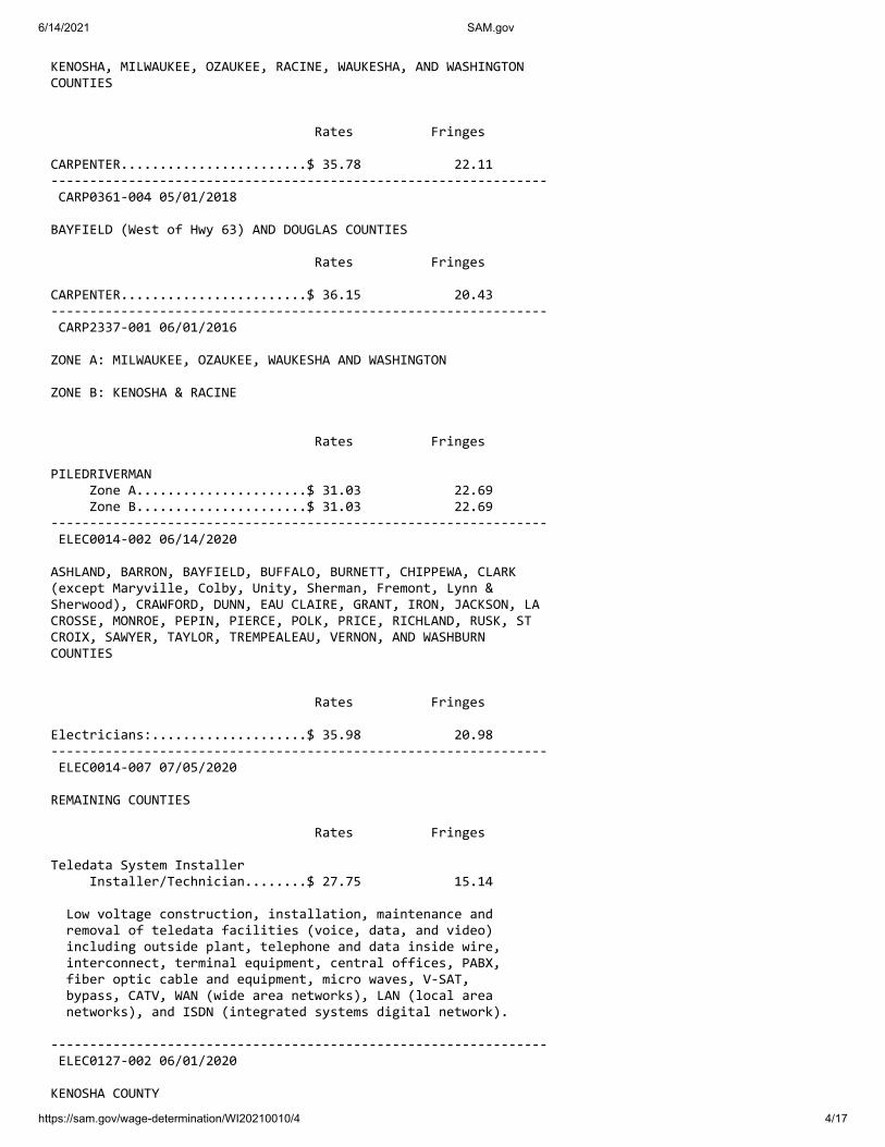
6/14/2021 SAM.gov
https://sam.gov/wage-determination/WI20210010/4 4/17
KENOSHA, MILWAUKEE, OZAUKEE, RACINE, WAUKESHA, AND WASHINGTON COUNTIES
Rates Fringes
CARPENTER........................$ 35.78 22.11 ---------------------------------------------------------------- CARP0361-004 05/01/2018
BAYFIELD (West of Hwy 63) AND DOUGLAS COUNTIES
Rates Fringes
CARPENTER........................$ 36.15 20.43 ---------------------------------------------------------------- CARP2337-001 06/01/2016
ZONE A: MILWAUKEE, OZAUKEE, WAUKESHA AND WASHINGTON
ZONE B: KENOSHA & RACINE
Rates Fringes
PILEDRIVERMAN Zone A......................$ 31.03 22.69 Zone B......................$ 31.03 22.69 ---------------------------------------------------------------- ELEC0014-002 06/14/2020
ASHLAND, BARRON, BAYFIELD, BUFFALO, BURNETT, CHIPPEWA, CLARK (except Maryville, Colby, Unity, Sherman, Fremont, Lynn & Sherwood), CRAWFORD, DUNN, EAU CLAIRE, GRANT, IRON, JACKSON, LA CROSSE, MONROE, PEPIN, PIERCE, POLK, PRICE, RICHLAND, RUSK, ST CROIX, SAWYER, TAYLOR, TREMPEALEAU, VERNON, AND WASHBURN COUNTIES
Rates Fringes
Electricians:....................$ 35.98 20.98 ---------------------------------------------------------------- ELEC0014-007 07/05/2020
REMAINING COUNTIES
Rates Fringes
Teledata System Installer Installer/Technician........$ 27.75 15.14
Low voltage construction, installation, maintenance and removal of teledata facilities (voice, data, and video) including outside plant, telephone and data inside wire, interconnect, terminal equipment, central offices, PABX, fiber optic cable and equipment, micro waves, V-SAT, bypass, CATV, WAN (wide area networks), LAN (local area networks), and ISDN (integrated systems digital network).
---------------------------------------------------------------- ELEC0127-002 06/01/2020
KENOSHA COUNTY

6/14/2021 SAM.gov
https://sam.gov/wage-determination/WI20210010/4 5/17
Rates Fringes
Electricians:....................$ 41.62 30%+12.70 ---------------------------------------------------------------- ELEC0158-002 06/01/2020
BROWN, DOOR, KEWAUNEE, MANITOWOC (except Schleswig), MARINETTE(Wausuakee and area South thereof), OCONTO, MENOMINEE (East of a ine 6 miles West of the West boundary of Oconto County), SHAWANO (Except Area North of Townships of Aniwa and Hutchins) COUNTIES
Rates Fringes
ELECTRICIAN......................$ 34.77 29.75%+10.26 ---------------------------------------------------------------- ELEC0159-003 08/02/2020
COLUMBIA, DANE, DODGE (Area West of Hwy 26, except Chester and Emmet Townships), GREEN, LAKE (except Townships of Berlin, Seneca, and St. Marie), IOWA, MARQUETTE (except Townships of Neshkoka, Crystal Lake, Newton, and Springfield), and SAUK COUNTIES
Rates Fringes
ELECTRICIAN......................$ 41.86 22.67 ---------------------------------------------------------------- ELEC0219-004 06/01/2019
FLORENCE COUNTY (Townships of Aurora, Commonwealth, Fern, Florence and Homestead) AND MARINETTE COUNTY (Township of Niagara)
Rates Fringes
Electricians: Electrical contracts over $180,000....................$ 33.94 21.80 Electrical contracts under $180,000....................$ 31.75 21.73 ---------------------------------------------------------------- ELEC0242-005 05/31/2020
DOUGLAS COUNTY
Rates Fringes
Electricians:....................$ 39.77 28.11 ---------------------------------------------------------------- ELEC0388-002 06/01/2020
ADAMS, CLARK (Colby, Freemont, Lynn, Mayville, Sherman, Sherwood, Unity), FOREST, JUNEAU, LANGLADE, LINCOLN, MARATHON, MARINETTE (Beecher, Dunbar, Goodman & Pembine), MENOMINEE (Area West of a line 6 miles West of the West boundary of Oconto County), ONEIDA, PORTAGE, SHAWANO (Aniwa and Hutchins), VILAS AND WOOD COUNTIES
Rates Fringes

6/14/2021 SAM.gov
https://sam.gov/wage-determination/WI20210010/4 6/17
Electricians:....................$ 34.85 26%+11.20 ---------------------------------------------------------------- ELEC0430-002 02/02/2021
RACINE COUNTY (Except Burlington Township)
Rates Fringes
Electricians:....................$ 41.859 22.871 ---------------------------------------------------------------- ELEC0494-005 06/01/2020
MILWAUKEE, OZAUKEE, WASHINGTON, AND WAUKESHA COUNTIES
Rates Fringes
Electricians:....................$ 42.84 25.54 ---------------------------------------------------------------- ELEC0494-006 06/01/2020
CALUMET (Township of New Holstein), DODGE (East of Hwy 26 including Chester Township), FOND DU LAC, MANITOWOC (Schleswig), and SHEBOYGAN COUNTIES
Rates Fringes
Electricians:....................$ 36.32 22.51 ---------------------------------------------------------------- ELEC0494-013 06/07/2020
DODGE (East of Hwy 26 including Chester Twp, excluding Emmet Twp), FOND DU LAC (Except Waupuin), MILWAUKEE, OZAUKEE, MANITOWOC (Schleswig), WASHINGTON, AND WAUKESHA COUNTIES
Rates Fringes
Sound & Communications Installer...................$ 21.46 18.52 Technician..................$ 31.34 20.00
Installation, testing, maintenance, operation and servicing of all sound, intercom, telephone interconnect, closed circuit TV systems, radio systems, background music systems, language laboratories, electronic carillion, antenna distribution systems, clock and program systems and low-voltage systems such as visual nurse call, audio/visual nurse call systems, doctors entrance register systems. Includes all wire and cable carrying audio, visual, data, light and radio frequency signals. Includes the installation of conduit, wiremold, or raceways in existing structures that have been occupied for six months or more where required for the protection of the wire or cable, but does not mean a complete conduit or raceway system. work covered does not include the installation of conduit, wiremold or any raceways in any new construction, or the installation of power supply outlets by means of which external electric power is supplied to any of the foregoing equipment or products
---------------------------------------------------------------- ELEC0577-003 06/01/2020

6/14/2021 SAM.gov
https://sam.gov/wage-determination/WI20210010/4 7/17
CALUMET (except Township of New Holstein), GREEN LAKE (N. part including Townships of Berlin, St Marie, and Seneca), MARQUETTE (N. part including Townships of Crystal Lake, Neshkoro, Newton, and Springfield), OUTAGAMIE, WAUPACA, WAUSHARA, AND WINNEBAGO COUNTIES
Rates Fringes
Electricians:....................$ 34.23 29.50%+10.00 ---------------------------------------------------------------- ELEC0890-003 06/01/2020
DODGE (Emmet Township only), GREEN, JEFFERSON, LAFAYETTE, RACINE (Burlington Township), ROCK AND WALWORTH COUNTIES
Rates Fringes
Electricians:....................$ 37.41 25.95%+11.11 ---------------------------------------------------------------- ELEC0953-001 06/02/2019
Rates Fringes
Line Construction: (1) Lineman.................$ 47.53 21.43 (2) Heavy Equipment Operator....................$ 42.78 19.80 (3) Equipment Operator......$ 38.02 18.40 (4) Heavy Groundman Driver..$ 33.27 16.88 (5) Light Groundman Driver..$ 30.89 16.11 (6) Groundsman..............$ 26.14 14.60 ---------------------------------------------------------------- ENGI0139-005 06/01/2020
Rates Fringes
Power Equipment Operator Group 1.....................$ 41.62 23.80 Group 2.....................$ 41.12 23.80 Group 3.....................$ 40.62 23.80 Group 4.....................$ 40.36 23.80 Group 5.....................$ 40.07 23.80 Group 6.....................$ 34.17 23.80
HAZARDOUS WASTE PREMIUMS: EPA Level ""A"" protection - $3.00 per hour EPA Level ""B"" protection - $2.00 per hour EPA Level ""C"" protection - $1.00 per hour
POWER EQUIPMENT OPERATORS CLASSIFICATIONS
GROUP 1: Cranes, tower cranes, and derricks with or without attachments with a lifting capacity of over 100 tons; or cranes, tower cranes, and derricks with boom, leads and/or jib lengths measuring 176 feet or longer.
GROUP 2: Cranes, tower cranes and derricks with or without attachments with a lifting capacity of 100 tons or less; or cranes, tower cranes, and derricks with boom, leads, and/or jibs lengths measuring 175 feet or under and Backhoes (excavators) weighing 130,000 lbs and over; caisson rigs; pile driver; dredge operator; dredge engineer; Boat Pilot.

6/14/2021 SAM.gov
https://sam.gov/wage-determination/WI20210010/4 8/17
GROUP 3: Mechanic or welder - Heavy duty equipment; cranes with a lifting capacity of 25 tons or under; concrete breaker (manual or remote); vibratory/sonic concrete breaker; concrete laser screed; concrete slipform paver; concrete batch plant operator; concrete pvt. spreader - heavy duty (rubber tired); concrete spreader & distributor; automatic subgrader (concrete); concrete grinder & planing machine; concrete slipform curb & gutter machine; slipform concrete placer; tube finisher; hydro blaster (10,000 psi & over); bridge paver; concrete conveyor system; concrete pump; Rotec type Conveyor; stabilizing mixer (self-propelled); shoulder widener; asphalt plant engineer; bituminious paver; bump cutter & grooving machine; milling machine; screed (bituminous paver); asphalt heater, planer & scarifier; Backhoes (excavators) weighing under 130,000 lbs; grader or motor patrol; tractor (scraper, dozer, pusher, loader); scraper - rubber tired (single or twin engine); endloader; hydraulic backhoe (tractor type); trenching machine; skid rigs; tractor, side boom (heavy); drilling or boring machine (mechanical heavy); roller over 5 tons; percussion or rotary drilling machine; air track; blaster; loading machine (conveyor); tugger; boatmen; winches & A-frames; post driver; material hoist.
GROUP 4: Greaser, roller steel (5 tons or less); roller (pneumatic tired) - self propelled; tractor (mounted or towed compactors & light equipment); shouldering machine; self- propelled chip spreader; concrete spreader; finishing machine; mechanical float; curing machine; power subgrader; joint sawer (multiple blade) belting machine; burlap machine; texturing machine; tractor endloader (rubber tired) - light; jeep digger; forklift; mulcher; launch operator; fireman, environmental burner
GROUP 5: Air compressor; power pack; vibrator hammer and extractor; heavy equipment, leadman; tank car heaters; stump chipper; curb machine operator; Concrete proportioning plants; generators; mudjack operator; rock breaker; crusher or screening plant; screed (milling machine); automatic belt conveyor and surge bin; pug mill operator; Oiler, pump (over 3 inches); Drilling Machine Tender, day light machine
GROUP 6: Off-road material hauler with or without ejector.
---------------------------------------------------------------- IRON0008-002 06/01/2020
BROWN, CALUMET, DOOR, FOND DU LAC, KEWAUNEE, MANITOWOC, MARINETTE, OCONTO, OUTAGAMI, SHAWANO, SHEBOYGAN, AND WINNEBAGO COUNTIES:
Rates Fringes
IRONWORKER.......................$ 37.31 27.62
Paid Holidays: New Year's Day, Memorial Day, July 4th, Labor Day, Thanksgiving Day & Christmas Day.
---------------------------------------------------------------- IRON0008-003 06/01/2020
KENOSHA, MILWAUKEE, OZAUKEE, RACINE, WALWORTH (N.E. 2/3), WASHINGTON, AND WAUKESHA COUNTIES

6/14/2021 SAM.gov
https://sam.gov/wage-determination/WI20210010/4 9/17
Rates Fringes
IRONWORKER.......................$ 39.11 27.87
Paid Holidays: New Year's Day, Memorial Day, July 4th, Labor Day, Thanksgiving Day & Christmas Day.
---------------------------------------------------------------- IRON0383-001 06/01/2020
ADAMS, COLUMBIA, CRAWFORD, DANE, DODGE, FLORENCE, FOREST, GRANT, GREENE, (Excluding S.E. tip), GREEN LAKE, IOWA, JEFFERSON, JUNEAU, LA CROSSE, LAFAYETTE, LANGLADE, MARATHON, MARQUETTE, MENOMINEE, MONROE, PORTAGE, RICHLAND, ROCK (Northern area, vicinity of Edgerton and Milton), SAUK, VERNON, WAUPACA, WAUSHARA, AND WOOD COUNTIES
Rates Fringes
IRONWORKER.......................$ 37.10 27.06 ---------------------------------------------------------------- IRON0498-005 06/01/2019
GREEN (S.E. 1/3), ROCK (South of Edgerton and Milton), and WALWORTH (S.W. 1/3) COUNTIES:
Rates Fringes
IRONWORKER.......................$ 40.25 40.53 ---------------------------------------------------------------- IRON0512-008 06/03/2019
BARRON, BUFFALO, CHIPPEWA, CLARK, DUNN, EAU CLAIRE, JACKSON, PEPIN, PIERCE, POLK, RUSK, ST CROIX, TAYLOR, AND TREMPEALEAU COUNTIES
Rates Fringes
IRONWORKER.......................$ 37.60 29.40 ---------------------------------------------------------------- * IRON0512-021 05/03/2021
ASHLAND, BAYFIELD, BURNETT, DOUGLAS, IRON, LINCOLN, ONEIDA, PRICE, SAWYER, VILAS AND WASHBURN COUNTIES
Rates Fringes
IRONWORKER.......................$ 35.09 31.80 ---------------------------------------------------------------- LABO0113-002 06/01/2020
MILWAUKEE AND WAUKESHA COUNTIES
Rates Fringes
LABORER Group 1.....................$ 30.05 22.26 Group 2.....................$ 30.20 22.26 Group 3.....................$ 30.40 22.26

6/14/2021 SAM.gov
https://sam.gov/wage-determination/WI20210010/4 10/17
Group 4.....................$ 30.55 22.26 Group 5.....................$ 30.70 22.26 Group 6.....................$ 26.54 22.26
LABORERS CLASSIFICATIONS
GROUP 1: General Laborer; Tree Trimmer; Conduit Layer; Demolition and Wrecking Laborer; Guard Rail, Fence, and Bridge Builder; Landscaper; Multiplate Culvert Assembler; Stone Handler; Bituminous Worker (Shoveler, Loader, and Utility Man); Batch Truck Dumper or Cement Handler; Bituminous Worker (Dumper, Ironer, Smoother, and Tamper); Concrete Handler
GROUP 2: Air Tool Operator; Joint Sawer and Filler (Pavement); Vibrator or Tamper Operator (Mechanical Hand Operated); Chain Saw Operator; Demolition Burning Torch Laborer
GROUP 3: Bituminous Worker (Raker and Luteman); Formsetter (Curb, Sidewalk, and Pavement); Strike Off Man
GROUP 4: Line and Grade Specialist
GROUP 5: Blaster and Powderman
GROUP 6: Flagperson; traffic control person
---------------------------------------------------------------- LABO0113-003 06/01/2020
OZAUKEE AND WASHINGTON COUNTIES
Rates Fringes
LABORER Group 1.....................$ 29.30 22.26 Group 2.....................$ 29.40 22.26 Group 3.....................$ 29.45 22.26 Group 4.....................$ 29.65 22.26 Group 5.....................$ 29.50 22.26 Group 6.....................$ 26.39 22.26
LABORERS CLASSIFICATIONS
GROUP 1: General Laborer; Tree Trimmer; Conduit Layer; Demolition and Wrecking Laborer; Guard Rail, Fence, and Bridge Builder; Landscaper; Multiplate Culvert Assembler; Stone Handler; Bituminous Worker (Shoveler, Loader, and Utility Man); Batch Truck Dumper or Cement Handler; Bituminous Worker (Dumper, Ironer, Smoother, and Tamper); Concrete Handler
GROUP 2: Air Tool Operator; Joint Sawer and Filler (Pavement); Vibrator or Tamper Operator (Mechanical Hand Operated);
GROUP 3: Bituminous Worker (Raker and Luteman); Formsetter (Curb, Sidewalk, and Pavement); Strike Off Man
GROUP 4: Line and Grade Specialist
GROUP 5: Blaster; powderman
GROUP 6: Flagperson and Traffic Control Person
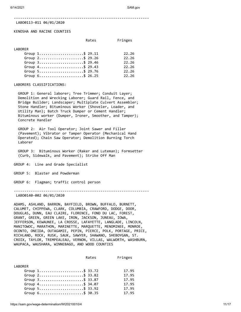
6/14/2021 SAM.gov
https://sam.gov/wage-determination/WI20210010/4 11/17
---------------------------------------------------------------- LABO0113-011 06/01/2020
KENOSHA AND RACINE COUNTIES
Rates Fringes
LABORER Group 1.....................$ 29.11 22.26 Group 2.....................$ 29.26 22.26 Group 3.....................$ 29.46 22.26 Group 4.....................$ 29.43 22.26 Group 5.....................$ 29.76 22.26 Group 6.....................$ 26.25 22.26
LABORERS CLASSIFICATIONS:
GROUP 1: General laborer; Tree Trimmer; Conduit Layer; Demolition and Wrecking Laborer; Guard Rail, Fence, and Bridge Builder; Landscaper; Multiplate Culvert Assembler; Stone Handler; Bituminous Worker (Shoveler, Loader, and Utility Man); Batch Truck Dumper or Cement Handler; Bituminous worker (Dumper, Ironer, Smoother, and Tamper); Concrete Handler
GROUP 2: Air Tool Operator; Joint Sawer and Filler (Pavement); Vibrator or Tamper Operator (Mechanical Hand Operated); Chain Saw Operator; Demolition Burning Torch Laborer
GROUP 3: Bituminous Worker (Raker and Luteman); Formsetter (Curb, Sidewalk, and Pavement); Strike Off Man
GROUP 4: Line and Grade Specialist
GROUP 5: Blaster and Powderman
GROUP 6: Flagman; traffic control person
---------------------------------------------------------------- LABO0140-002 06/01/2020
ADAMS, ASHLAND, BARRON, BAYFIELD, BROWN, BUFFALO, BURNETT, CALUMET, CHIPPEWA, CLARK, COLUMBIA, CRAWFORD, DODGE, DOOR, DOUGLAS, DUNN, EAU CLAIRE, FLORENCE, FOND DU LAC, FOREST, GRANT, GREEN, GREEN LAKE, IRON, JACKSON, JUNEAU, IOWA, JEFFERSON, KEWAUNEE, LA CROSSE, LAFAYETTE, LANGLADE, LINCOLN, MANITOWOC, MARATHON, MARINETTE, MARQUETTE, MENOMINEE, MONROE, OCONTO, ONEIDA, OUTAGAMIE, PEPIN, PIERCE, POLK, PORTAGE, PRICE, RICHLAND, ROCK, RUSK, SAUK, SAWYER, SHAWANO, SHEBOYGAN, ST. CROIX, TAYLOR, TREMPEALEAU, VERNON, VILLAS, WALWORTH, WASHBURN, WAUPACA, WAUSHARA, WINNEBAGO, AND WOOD COUNTIES
Rates Fringes
LABORER Group 1.....................$ 33.72 17.95 Group 2.....................$ 33.82 17.95 Group 3.....................$ 33.87 17.95 Group 4.....................$ 34.07 17.95 Group 5.....................$ 33.92 17.95 Group 6.....................$ 30.35 17.95

6/14/2021 SAM.gov
https://sam.gov/wage-determination/WI20210010/4 12/17
LABORER CLASSIFICATIONS
GROUP 1: General Laborer; Tree Trimmer; Conduit Layer; Demolition and Wrecking Laborer; Guard Rail, Fence, and Bridge Builder; Landscaper; Multiplate Culvert Assembler; Stone Handler; Bitminous Worker (Shoveler, Loader, and Utility Man); Batch Truck Dumper or Cement Handler; Bituminous Worker (Dumper, Ironer, Smoother and Tamper); Concrete Handler
GROUP 2: Air Tool Operator; Joint Sawer and Filler (Pavement); Vibrator or Tamper Operator (Mechanical Hand Operated); Chain Saw Operator, Demolition Burning Torch Laborer
GROUP 3: Bituminous Worker (Raker and Luteman); Formsetter (Curb, Sidewalk and Pavement); Strike Off Man
GROUP 4: Line and Grade Secialist
GROUP 5: Blaster; powderman
GROUP 6: Flagperson; Traffic Control
---------------------------------------------------------------- LABO0464-003 06/01/2020
DANE COUNTY
Rates Fringes
LABORER Group 1.....................$ 34.00 17.95 Group 2.....................$ 34.10 17.95 Group 3.....................$ 34.15 17.95 Group 4.....................$ 34.35 17.95 Group 5.....................$ 34.20 17.95 Group 6.....................$ 30.35 17.95
LABORERS CLASSIFICATIONS:
GROUP 1: General Laborer; Tree Trimmer; Conduit Layer; Demolition and Wrecking Laborer; Guard Rail, Fence, and Bridge Builder; Landscaper; Multiplate Culvert Assembler; Stone Handler; Bituminous Worker (Shoveler, Loader, and Utility Man); Batch Truck Dumper or Cement Handler; Bituminious Worker (Dumper, Ironer, Smoother, and Tamper); Concrete Handler
GROUP 2: Air Tool Operator; Joint Sawer and Filler (Pavement); Vibrator or Tamper Operator (Mechanical Hand Operated); Chain Saw Operator; Demolition Burning Torch Laborer
GROUP 3: Bituminous Worker (Raker and Luteman); Formsetter (Curb, Sidewalk, and Pavement); Strike Off Man
GROUP 4: Line and Grade Specialist
GROUP 5: Blaster; Powderman
GROUP 6: Flagperson and Traffic Control Person
---------------------------------------------------------------- PAIN0106-008 05/01/2017

6/14/2021 SAM.gov
https://sam.gov/wage-determination/WI20210010/4 13/17
ASHLAND, BAYFIELD, BURNETT, AND DOUGLAS COUNTIES
Rates Fringes
Painters: New: Brush, Roller..............$ 30.33 17.27 Spray, Sandblast, Steel....$ 30.93 17.27 Repaint: Brush, Roller..............$ 28.83 17.27 Spray, Sandblast, Steel....$ 29.43 17.27 ---------------------------------------------------------------- PAIN0108-002 06/01/2019
RACINE COUNTY
Rates Fringes
Painters: Brush, Roller...............$ 36.08 20.36 Spray & Sandblast...........$ 37.08 20.36 ---------------------------------------------------------------- PAIN0259-002 05/01/2008
BARRON, CHIPPEWA, DUNN, EAU CLAIRE, PEPIN, PIERCE, POLK, RUSK, SAWYER, ST. CROIX, AND WASHBURN COUNTIES
Rates Fringes
PAINTER..........................$ 24.11 12.15 ---------------------------------------------------------------- PAIN0259-004 05/01/2015
BUFFALO, CRAWFORD, JACKSON, LA CROSSE, MONROE, TREMPEALEAU, AND VERNON COUNTIES
Rates Fringes
PAINTER..........................$ 22.03 12.45 ---------------------------------------------------------------- PAIN0781-002 06/01/2019
JEFFERSON, MILWAUKEE, OZAUKEE, WASHINGTON, AND WAUKESHA COUNTIES
Rates Fringes
Painters: Bridge......................$ 33.30 23.86 Brush.......................$ 32.95 23.86 Spray & Sandblast...........$ 33.70 23.86 ---------------------------------------------------------------- PAIN0802-002 06/01/2019
COLUMBIA, DANE, DODGE, GRANT, GREEN, IOWA, LAFAYETTE, RICHLAND, ROCK, AND SAUK COUNTIES
Rates Fringes
PAINTER Brush.......................$ 30.93 18.44

6/14/2021 SAM.gov
https://sam.gov/wage-determination/WI20210010/4 14/17
PREMIUM PAY: Structural Steel, Spray, Bridges = $1.00 additional per hour.
---------------------------------------------------------------- PAIN0802-003 06/01/2019
ADAMS, BROWN, CALUMET, CLARK, DOOR, FOND DU LAC, FOREST, GREEN LAKE, IRON, JUNEAU, KEWAUNEE, LANGLADE, LINCOLN, MANITOWOC, MARATHON, MARINETTE, MARQUETTE, MENOMINEE, OCONTO, ONEIDA, OUTAGAMIE, PORTAGE, PRICE, SHAWANO, SHEBOYGAN, TAYLOR, VILAS, WAUSHARA, WAUPACA, WINNEBAGO, AND WOOD COUNTIES
Rates Fringes
PAINTER..........................$ 30.93 18.58 ---------------------------------------------------------------- PAIN0934-001 06/01/2017
KENOSHA AND WALWORTH COUNTIES
Rates Fringes
Painters: Brush.......................$ 33.74 18.95 Spray.......................$ 34.74 18.95 Structural Steel............$ 33.89 18.95 ---------------------------------------------------------------- PAIN1011-002 06/02/2019
FLORENCE COUNTY
Rates Fringes
Painters:........................$ 25.76 13.33 ---------------------------------------------------------------- PLAS0599-010 06/01/2017
Rates Fringes
CEMENT MASON/CONCRETE FINISHER Area 1......................$ 39.46 17.17 Area 2 (BAC)................$ 35.07 19.75 Area 3......................$ 35.61 19.40 Area 4......................$ 34.70 20.51 Area 5......................$ 36.27 18.73 Area 6......................$ 32.02 22.99
AREA DESCRIPTIONS
AREA 1: BAYFIELD, DOUGLAS, PRICE, SAWYER, AND WASHBURN COUNTIES
AREA 2: ADAMS, ASHLAND, BARRON, BROWN, BURNETT, CALUMET, CHIPPEWA, CLARK, COLUMBIA, DODGE, DOOR, DUNN, FLORENCE, FOND DU LAC, FOREST, GREEN LAKE, IRON, JEFFERSON, KEWAUNEE, LANGLADE, LINCOLN, MANITOWOC, MARATHON, MARINETTE, MARQUETTE, MENOMINEE, OCONTO, ONEIDA, OUTAGAMIE, POLK, PORTAGE, RUSK, ST CROIX, SAUK, SHAWANO, SHEBOYGAN, TAYLOR, VILAS, WALWORTH, WAUPACA, WAUSHARA, WINNEBAGO, AND WOOD COUNTIES
AREA 3: BUFFALO, CRAWFORD, EAU CLAIRE, JACKSON, JUNEAU, LA CROSSE MONROE, PEPIN, PIERCE, RICHLAND, TREMPEALEAU, AND

6/14/2021 SAM.gov
https://sam.gov/wage-determination/WI20210010/4 15/17
VERNON COUNTIES
AREA 4: MILWAUKEE, OZAUKEE, WASHINGTON, AND WAUKESHA COUNTIES
AREA 5: DANE, GRANT, GREEN, IOWA, LAFAYETTE, AND ROCK COUNTIES
AREA 6: KENOSHA AND RACINE COUNTIES
---------------------------------------------------------------- TEAM0039-001 06/01/2020
Rates Fringes
TRUCK DRIVER 1 & 2 Axles.................$ 31.07 22.94 3 or more Axles; Euclids, Dumptor & Articulated, Truck Mechanic..............$ 31.22 22.94 ------------------------------------------------------------ WELL DRILLER.....................$ 16.52 3.70 ----------------------------------------------------------------
WELDERS - Receive rate prescribed for craft performing operation to which welding is incidental.
================================================================ Note: Executive Order (EO) 13706, Establishing Paid Sick Leave for Federal Contractors applies to all contracts subject to the Davis-Bacon Act for which the contract is awarded (and any solicitation was issued) on or after January 1, 2017. If this contract is covered by the EO, the contractor must provide employees with 1 hour of paid sick leave for every 30 hours they work, up to 56 hours of paid sick leave each year. Employees must be permitted to use paid sick leave for their own illness, injury or other health-related needs, including preventive care; to assist a family member (or person who is like family to the employee) who is ill, injured, or has other health-related needs, including preventive care; or for reasons resulting from, or to assist a family member (or person who is like family to the employee) who is a victim of, domestic violence, sexual assault, or stalking. Additional information on contractor requirements and worker protections under the EO is available at www.dol.gov/whd/govcontracts.
Unlisted classifications needed for work not included within the scope of the classifications listed may be added after award only as provided in the labor standards contract clauses (29CFR 5.5 (a) (1) (ii)).
----------------------------------------------------------------
The body of each wage determination lists the classification and wage rates that have been found to be prevailing for the cited type(s) of construction in the area covered by the wage determination. The classifications are listed in alphabetical order of ""identifiers"" that indicate whether the particular rate is a union rate (current union negotiated rate for local), a survey rate (weighted average rate) or a union average rate (weighted union average rate).
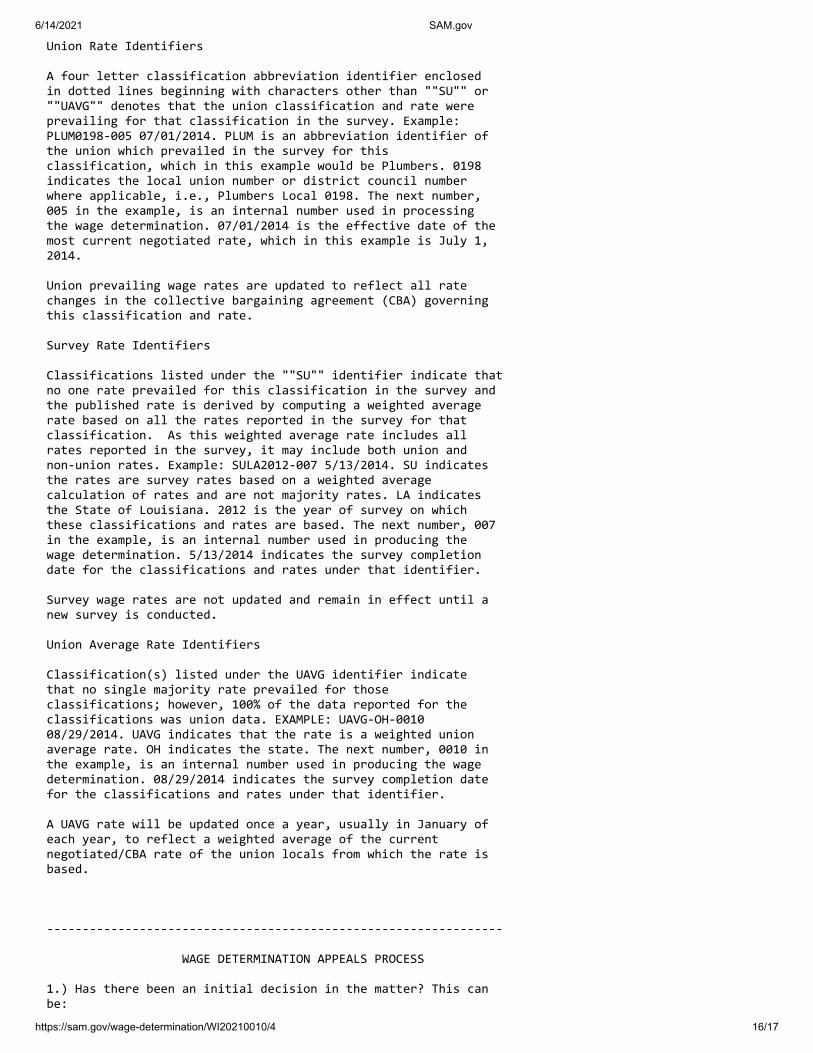
6/14/2021 SAM.gov
https://sam.gov/wage-determination/WI20210010/4 16/17
Union Rate Identifiers
A four letter classification abbreviation identifier enclosed in dotted lines beginning with characters other than ""SU"" or ""UAVG"" denotes that the union classification and rate were prevailing for that classification in the survey. Example: PLUM0198-005 07/01/2014. PLUM is an abbreviation identifier of the union which prevailed in the survey for this classification, which in this example would be Plumbers. 0198 indicates the local union number or district council number where applicable, i.e., Plumbers Local 0198. The next number, 005 in the example, is an internal number used in processing the wage determination. 07/01/2014 is the effective date of the most current negotiated rate, which in this example is July 1, 2014.
Union prevailing wage rates are updated to reflect all rate changes in the collective bargaining agreement (CBA) governing this classification and rate.
Survey Rate Identifiers
Classifications listed under the ""SU"" identifier indicate that no one rate prevailed for this classification in the survey and the published rate is derived by computing a weighted average rate based on all the rates reported in the survey for that classification. As this weighted average rate includes all rates reported in the survey, it may include both union and non-union rates. Example: SULA2012-007 5/13/2014. SU indicates the rates are survey rates based on a weighted average calculation of rates and are not majority rates. LA indicates the State of Louisiana. 2012 is the year of survey on which these classifications and rates are based. The next number, 007 in the example, is an internal number used in producing the wage determination. 5/13/2014 indicates the survey completion date for the classifications and rates under that identifier.
Survey wage rates are not updated and remain in effect until a new survey is conducted.
Union Average Rate Identifiers
Classification(s) listed under the UAVG identifier indicate that no single majority rate prevailed for those classifications; however, 100% of the data reported for the classifications was union data. EXAMPLE: UAVG-OH-0010 08/29/2014. UAVG indicates that the rate is a weighted union average rate. OH indicates the state. The next number, 0010 in the example, is an internal number used in producing the wage determination. 08/29/2014 indicates the survey completion date for the classifications and rates under that identifier.
A UAVG rate will be updated once a year, usually in January of each year, to reflect a weighted average of the current negotiated/CBA rate of the union locals from which the rate is based.
----------------------------------------------------------------
WAGE DETERMINATION APPEALS PROCESS
1.) Has there been an initial decision in the matter? This can be:

6/14/2021 SAM.gov
https://sam.gov/wage-determination/WI20210010/4 17/17
* an existing published wage determination * a survey underlying a wage determination * a Wage and Hour Division letter setting forth a position on a wage determination matter * a conformance (additional classification and rate) ruling
On survey related matters, initial contact, including requests for summaries of surveys, should be with the Wage and Hour Regional Office for the area in which the survey was conducted because those Regional Offices have responsibility for the Davis-Bacon survey program. If the response from this initial contact is not satisfactory, then the process described in 2.) and 3.) should be followed.
With regard to any other matter not yet ripe for the formal process described here, initial contact should be with the Branch of Construction Wage Determinations. Write to:
Branch of Construction Wage Determinations Wage and Hour Division U.S. Department of Labor 200 Constitution Avenue, N.W. Washington, DC 20210
2.) If the answer to the question in 1.) is yes, then an interested party (those affected by the action) can request review and reconsideration from the Wage and Hour Administrator (See 29 CFR Part 1.8 and 29 CFR Part 7). Write to:
Wage and Hour Administrator U.S. Department of Labor 200 Constitution Avenue, N.W. Washington, DC 20210
The request should be accompanied by a full statement of the interested party's position and by any information (wage payment data, project description, area practice material, etc.) that the requestor considers relevant to the issue.
3.) If the decision of the Administrator is not favorable, an interested party may appeal directly to the Administrative Review Board (formerly the Wage Appeals Board). Write to:
Administrative Review Board U.S. Department of Labor 200 Constitution Avenue, N.W. Washington, DC 20210
4.) All decisions by the Administrative Review Board are final.
================================================================
END OF GENERAL DECISION"

THIS PAGE INTENTIONALLY LEFT BLANK

Project #00320024 Funding Requirements© 2021 MSA Professional Services, Inc. 00 80 00-1
SECTION 00 80 0012
FUNDING REQUIREMENTS3
PART 1 GENERAL4
1.01 APPLICABLE PROVISIONS5
A. Applicable provisions of Division 01 shall govern work of this section.6
1.02 APPLICABLE PUBLICATIONS (NONE)7
1.03 DESCRIPTION OF WORK8
A. It is anticipated that a variety of Federal, State and Local funds will be utilized for9the project. The Contractor shall follow all requirements outlined below and10elsewhere in the Contract Documents for each type of funding.11
1.04 RELATED WORK ELSEWHERE12
A. Procurement and Contracting Requirements - Division 00 (All Sections)13
1.05 SUBMITTALS14
A. Closeout Procedures, Section 01 77 00, 1.05 Submittals. Note that some submittals15are ongoing throughout the project.16
1.06 THE DEPARTMENT OF THE ARMY FEDERAL SECTION 154 PROGRAM GRANT17
A. This project will utilize funds from the Section 154 Program grant is pursuant to18Section 154 of Division B of Appendix D, Consolidated Appropriations act, 2001,19Public Law 106-554, as amended (“Section 154 Program”). This program is a federal20program and the funds will be distributed through the U.S. Army Engineer, Detroit21District. (Army Corps of Engineers – “USACE”)22
B. The Section 154 Program grant has several requirements which are outlined in23section 1.08 below. The contractor is responsible to perform its responsibilities in24accordance with the regulations, plans, and specifications to meet the satisfactory25requirements and schedules for compliance with this program and also the Harbor26Assistance Program below.27
1.07 THE WISCONSIN DEPARTMENT OF TRANSPORTATION HARBOR ASSISTANCE28PROGRAM GRANT29
A. This project will utilize funds from the Harbor Assistance Program (“HAP”) as30authorized by s.85.095 Stats, and described in the Wisconsin Department of31Transportation (WisDOT) Administrative Code Trans 28. This program is a state32program.33

Project #00320024 Funding Requirements© 2021 MSA Professional Services, Inc. 00 80 00-2
B. HAP Fund regulations and requirements are included in section 1.08 below. The1contractor is responsible to perform its responsibilities in accordance with the2regulations, plans, and specifications to meet the satisfactory requirements and3schedules for compliance with this program and also the ACOE Section 1544Program.5
1.08 FEDERAL AND STATE FUNDING REQUIREMENTS6
A. The prime contractor is responsible to assure compliance for all work performed7under its contract. The prime contractor is required to provide requested evidence of8compliance to the OWNER or OWNER’s agents for itself and any subcontractors.9
B. The prime contractor is responsible to include these compliance provisions in all10subcontracts. It is recommended that this section 00 80 00 be attached to11subcontracts, along with the applicable wage decision(s). Electronic copies of all12subcontracts must be provided to the OWNER.13
C. The Project is using funds which are subject to the following federal and state14requirements, including:151. Federal Labor Laws:16
a. Section 154: Federal labor laws covering non-Federal construction,17including, but not limited to, 40 U.S.C. 3141-3148 and 40 U.S.C.183701-3708 (revising, codifying and enacting without substantive19change the provisions of the Davis-Bacon Act (formerly 40 U.S.C.20276a et seq.), the Contract Work Hours and Safety Standards Act21(formerly 40 U.S.C. 327 et seq.) and the Copeland Anti- Kickback22Act (formerly 40 U.S.C. 276c)). Notwithstanding any other provision23of this Agreement, inclusion of costs for construction in total project24costs may be withheld, in whole or in part, as a result of the25contractor’s or its subcontractors’ failure to comply with its26obligations under these laws.27
b. The latest available Federal Wage Rate decision is included in28Division 00 71 01.29
c. If a new decision is issued prior to or on the date of the bid, that30decision becomes the prevailing wage decision for the project.31
d. The applicable wage decision(s) must be posted on the job site in a32conspicuous and accessible location.33
e. Failure to comply with Davis-Bacon requirements will result in34debarment and/or other penalties.35
f. Instructions for Completion of Payroll (Form WH-347). The use of36WH-347, payroll form, while not mandatory, is suggested. This form37has been made available for the convenience of contractors and38subcontractors required by their federal or federally-aided39construction-type contracts and subcontracts to submit weekly40payrolls. If an alternate payroll form is used it MUST provide all data41shown and required on the front and back of WH-347.42

Project #00320024 Funding Requirements© 2021 MSA Professional Services, Inc. 00 80 00-3
g. Statement of Compliance. Under the Davis-Bacon law, the1contractor is required to pay fringe benefits as predetermined by the2USDOL, in addition to payment of the minimum rates. The3contractor’s obligation to pay fringe benefits may be met by payment4of the various plans, funds, or programs or by making these payments5to the employees as cash in lieu of fringes. Each contractor should6complete a Statement of Compliance with the fringe benefit7provisions.8
2. In carrying out its obligations under this Agreement, the Contractor shall9comply with all requirements of the following additional applicable federal10laws and implementing regulations prescribed by the Section 154 Program,11including, but not limited to: Section 601 of the Civil Rights Act of 196412(P.L. 88-352), as amended (42 U.S.C. 2000d), and Department of Defense13Directive 5500.11 issued pursuant thereto; the Age Discrimination Act of141975 (42 U.S.C. 6102); the Rehabilitation Act of 1973, as amended (2915U.S.C. 794), and Army Regulation 600-7 issued pursuant thereto.16
3. In addition, the HAP grant identifies the following requirements for17compliance:18a. HAP Nondiscrimination Clause, also to be inserted in all19
subcontracts: In connection with the performance of work under this20AGREEMENT, Contractor agrees not to discriminate against any21employee or applicant for employment because of age, race, religion,22color, handicap, sex, physical condition, developmental disability as23defined in Section 51.01(5), Wis. Stats., sexual orientation or national24origin. This provision shall include, but not be limited to, the25following: employment, upgrading, demotion or transfer; recruitment26or recruitment advertising; layoff or termination; rates of pay or other27forms of compensation; and selection for training, including28apprenticeship. Except with respect to sexual orientation, Contractor29further agrees to take affirmative action to ensure equal employment30opportunities. Contractor agrees to post notices in conspicuous31places, available for employees and applicants for employment.32Notice is included in Division 00 of these specifications.33
b. Title VI of the Civil Rights Act of 1964, 78 Stat. 252, 42 U.S.C.342000d et seq.35
c. Title II and Title III of the Uniform Relocation Assistance and Real36Property Acquisition Policies Act of 1970, 42 U.S.C. 4601 et seq.37
d. Subchapter II of Section 111, Wis. Stats.38e. Americans with Disabilities Act of 1990, 42 U.S.C. 12101, et seq.39f. Federal Occupational Safety and Health Act of 1970, 29 U.S.C. 653,40
et seq., and any other applicable occupational safety and health laws41or regulations.42
4. All work performed for the project is subject to on-site inspection by the43federal representative for the Section 154 Program and the state44representative for the HAP Program to determine that the work was45accomplished in a satisfactory manner and is suitable for inclusion in the46

Project #00320024 Funding Requirements© 2021 MSA Professional Services, Inc. 00 80 00-4
project. This is in addition to the normal monitoring by the RPR and1representative(s) from the City2
5. Work will be done in compliance with NEPA and the Wisconsin3Environmental Policy Act, Section 1.11, Wis. Stats; Section 401 of the4Federal Water Pollution Control Act (FWPCA) 33 U.S.C. 1341 and Section5308, FWPCA, 33 USC 1318 and related; and the requirements of Section 1146of the Clean Air Act, 42 USC 7414.7
6. Conflict of Interest Form in section 00 required to be submitted with bid.8Conflict of interest disclosure is required for any real or apparent conflict of9interest (either for themselves or those with whom they have family or10business ties during their tenure or for one year thereafter) covering11contractor, subcontractor, city, agency personnel, or their agents.12a. HAP required statement: “No official, officer or employee of the City13
during his or her tenure or for one year thereafter, shall have any14interest, direct or indirect, in this contract or in the proceeds thereof15except as permitted under Section 946.13 (2), Wis. Stats.”16
7. Due to the funding, there are regular reporting requirements and the City is17subject to federal single audit(s). In addition, all records related to the project18must be maintained for a period of at least three years after the final19accounting for the project. The contractor will provide to the City or its agent20the records in a timely fashion and as requested to meet these obligations.21
D. Project Signage. Any project sign may contain identification of the funding and the22official WisDOT and USACE Logos.23
24
PART 2 PRODUCTS AND MATERIALS (N/A)25
PART 3 CONSTRUCTION METHODS (N/A)26
PART 4 MEASUREMENT AND PAYMENT27
4.01 FUNDING REQUIREMENTS28
A. Work associated with the funding requirements of the project is considered incidental29and no additional payments will be made for satisfying these requirements.30
31END OF SECTION32

Project #00320024 Summary of Work© 2021 MSA Professional Services, Inc. 01 11 00-1
SECTION 01 11 00
SUMMARY OF WORK
PART 1 GENERAL
1.01 APPLICABLE PROVISIONS
A. Applicable provisions of Division 01 shall govern work of this section.
1.02 APPLICABLE PUBLICATIONS (NONE)
1.03 DESCRIPTION OF WORK
A. All work areas identified in this specification are shown on the bid drawings.
B. Demolition of existing walkways along the east breakwall in preparation forreplacement.
C. Demolition of wood retaining wall, walkway, and selected utilities on A Dock.
D. Removal disposal of concrete riprap along the South Shoreline. Stone riprap maybe reused as core stone on the armored East Breakwall structure.
E. Furnish and install steel sheet pile for the east breakwall and A Dock.
F. Furnish and install tubing to connect circulation tunnels.
G. Furnish and install Armorstone protection at East Breakwall and along SouthShoreline.
H. Install utilities for A dock and East Breakwall.
I. Install new decking and accessories for East Breakwall.
1.04 WORK SCHEDULE
A. Work on the South Shoreline and the outboard armorstone of the East Breakwallconstruction may begin with the Notice to Proceed.
B. Work inside the marina basin may not begin prior to October 15, 2021 andnotification from the Marina Manager that the boats have been cleared from thework area.
PART 2 PRODUCTS (Not Included)
PART 3 EXECUTION (Not Included)END OF SECTION

THIS PAGE INTENTIONALLY LEFT BLANK

Project #03200024 Project Meetings© 2021 MSA Professional Services, Inc. 01 31 19-1
SECTION 01 31 19
PROJECT MEETINGS
PART 1 GENERAL
1.01 APPLICABLE PROVISIONS
A. Applicable provisions of Division 01 shall govern work of this section.
1.02 DESCRIPTION OF WORK
A. Preconstruction Meeting. A Preconstruction Meeting will be scheduled andconducted by the Engineer and shall be attended by representatives of the Owner,Contractor and all subcontractors as deemed required by the Engineer. Thepurpose of the meeting will be to identify all project participants, review projectrequirements and specifications, establish the method of making pay requests andother matters that may be deemed necessary to be discussed. At this meeting, theContractor shall submit the proposed construction schedule for review, consensusby the parties and approval. The Contractor shall also submit a schedule of valuesfor the work to be used as the accounting format for all progress payments.
B. Construction Progress Meetings. Brief weekly meetings, as deemed necessary bythe Engineer, will be held and shall be attended by all Contractors. The purposeof the meeting will be to coordinate work schedules, review the project progressand other matters that may be deemed necessary to be discussed.1. A construction progress meeting agenda shall be prepared as deemed
necessary to the Engineer.2. All construction progress meeting attendees shall be fully prepared prior to
the meeting and shall be ready to discuss issues raised as they relate totheir work. This shall include, but not be limited to, providing revisedschedules, milestone activities, specific requirements for subordinateconstruction and any proposed or completed changes required for theirwork.
1.03 RELATED WORK ELSEWHERE
A. Procurement and Contracting Requirements - Division 00 (All Sections)
1.04 SUBMITTALS (NONE)
1.05 OPERATION/MAINTENANCE MANUALS AND INSTRUCTIONS (NONE)
PART 2 PRODUCTS (N/A)
PART 3 EXECUTION (N/A)
END OF SECTION

THIS PAGE INTENTIONALLY LEFT BLANK

Project #0030024 Construction Progress Schedule © 2021 MSA Professional Services, Inc. 01 32 16-1
SECTION 01 32 16
CONSTRUCTION PROGRESS SCHEDULE
PART 1 GENERAL
1.01 APPLICABLE PROVISIONS
A. Applicable provisions of Division 01 shall govern work of this section.
1.02 DESCRIPTION OF WORK
A. Submit preliminary Construction Progress Schedule in accordance with General Conditions prior to pre-construction conference.
B. The Contractor shall comply with and the Work shall be completed in accordance
with the following construction schedule:
1. Award Contract (August 2, 2021– Tentative)
2. South Shoreline Notice to Proceed (August 16, 2021 – Tentative)
3. Outboard face of East Breakwall Notice to Proceed (August 16, 2021 –
Tentative)
4. Inboard face of East Breakwall and A Dock Notice to Proceed (October
18, 2021 – Tentative)
5. Substantial Completion. Substantial Completion shall be completed by
April 15, 2022.
6. Final Completion. The project shall be completed by April 30, 2022.
Final Completion shall include all work as shown on the Contract
Drawings and detailed in these specifications, including the all items
addressed in final project closeout punchlist.
7. Within 30 days of final completion, submit final project closeout
documentation inclusive of lien waivers, affidavit of compliance with
prevailing wage rate determination, and final pay request.
1.03 RELATED WORK ELSEWHERE
A. Procurement and Contracting Requirements - Division 00 (All Sections)
1.04 SUBMITTALS
A. Furnish electronic (pdf, Excel, or Word) copies of preliminary schedule, and subsequent revisions thereof, to Engineer three (3) days before each progress meeting.
B. Within three (3) days after monthly progress meetings, furnish electronic copies of revised schedule to Engineer. Furnish revised schedule to Subcontractors as appropriate.

Project #0030024 Construction Progress Schedule© 2021 MSA Professional Services, Inc. 01 32 16-2
C. Failure to submit schedules on a timely basis shall be considered cause forwithholding progress payments.
PART 2 PRODUCTS (none)
PART 3 EXECUTION
3.01 FORM OF SCHEDULE
A. Prepare schedule in form of horizontal bar chart.1. Provide separate horizontal bar for each trade, activity or operation.2. Provide continuous vertical line to identify first working day of each
week.3. Scale and space to allow for notations and future revisions.
3.02 CONTENT OF SCHEDULE
A. Show complete sequence of construction by activity or operation.
B. Show dates for beginning and completion of each major element of constructionand installation dates for major equipment items. Include:1. Each individual task of construction.2. Procurement of equipment and systems including Shop Drawing
submittals, Engineer’s review of submittals, shop tests, and delivery dates.3. Identification of Work that will affect existing plant operations.4. Services of manufactures’ representatives.5. Startup dates for major equipment.6. Field tests.7. Dates of Substantial and Final completion.8. Subcontractor Work items.9. MBE, WBE, and SBE activities.10. O&M data activities11. Contractor-provided training.
C. Show projected percentage of completion for each activity as of first day of eachmonth.
3.03 REVISIONS TO SCHEDULE
A. Each month Contractor shall receive update information from Subcontractors andSuppliers that shall be included in current schedule. Revised schedule shallindicate changes such as:1. Major changes in scope.2. Activities modified since previous submittal.3. Revised projections of progress and completion.4. Other identifiable changes.
B. Provide narrative report to define following:

Project #0030024 Construction Progress Schedule© 2021 MSA Professional Services, Inc. 01 32 16-3
1. Problem area and anticipated delays and their impact on schedule.2. Corrective action recommended and its effect.
3.04 MONTHLY PROGRESS MEETINGS
A. Once each month Construction Progress Schedule will be reviewed. Progress willbe reviewed:1. To identify those activities started and completed during previous period.2. For remaining duration required to complete each activity started, but not
completed.3. For durations of selected activities not yet started.4. For effect of Change Orders and proposed sequencing.
B. Update schedule accordingly.
3.05 DELAYS AND RECOVERY
A. If, at any time during the Project, Contractor fails to complete activity by its latestscheduled completion date, Contractor shall, within five (5) working days, submitto Engineer written statement as to how and when work force will be reorganizedto return to current construction schedule.
B. If, during schedule review meetings, it becomes apparent that milestonecompletion dates or Contract completion dates will not be met, Contractor shalltake some or all of the following actions:1. Increase construction staffing in such quantities and crafts as shall
eliminate backlog of Work.2. Increase number of working hours per shift, shifts per day, Work days per
week, amount of construction equipment or combination of foregoingsufficient to substantially eliminate backlog of Work.
3. Reschedule Work actives to achieve concurrency of accomplishment
C. Under no circumstances will addition of equipment or construction forces,increasing working hours or other method, manner or procedure to return tocurrent Construction Progress Schedule be considered justification for Contractmodification or treated as acceleration.
END OF SECTION

THIS PAGE INTENTIONALLY LEFT BLANK

Project #00320024 Survey and Layout Data© 2021 MSA Professional Services, Inc. 01 32 23-1
SECTION 01 32 23
SURVEY AND LAYOUT DATA
PART 1 GENERAL
1.01 APPLICABLE PROVISIONS
A. Applicable provisions of Division 1 shall govern work of this section.
1.02 APPLICABLE PUBLICATIONS (NONE)
1.03 DESCRIPTION OF WORK
A. The Contractor will stake and layout all work. The Contractor shall immediatelyupon entering the site for purpose of beginning work, locate general referencepoints and take such action as necessary to prevent their destruction. TheContractor shall layout the work and be responsible for all lines, elevations andmeasurements. The Contractor must exercise proper precaution to verifydimensions of the drawings before laying out work and will be held responsiblefor any error resulting from failure to exercise such precaution.
1.04 RELATED WORK ELSEWHERE
A. Procurement and Contracting Requirements - Division 00 (All Sections)
1.05 SUBMITTALS (NONE)
PART 2 PRODUCTS (N/A)
PART 3 EXECUTION (N/A)
END OF SECTION

THIS PAGE INTENTIONALLY LEFT BLANK

Project #03200024 Submittals© 2021 MSA Professional Services, Inc. 01 33 00-1
SECTION 01 33 00
SUBMITTALS
PART 1 GENERAL
1.01 APPLICABLE PROVISIONS
A. Applicable provisions of Division 01 shall govern work of this section.
1.02 APPLICABLE PUBLICATIONS (NONE)
1.03 DESCRIPTION OF WORK
A. The work under this section shall cover furnishing submittal information asrequired by the contract drawings, other specification sections and as specifiedherein.
1.04 RELATED WORK ELSEWHERE
A. Procurement and Contracting Requirements - Division 00 (All Sections)
B. Submittal Log - Section 01 33 23
1.05 SUBMITTALS
A. As soon as possible after Notice to Proceed, submit brochures of catalog cuts andspecifications for all new equipment. Submittal of product data shall comply withthe requirements for Submittals.
B. Prior to fabrication or installation, submit Submittals for review. Each submittalshall consist of the electronic versions of the submittal conforming to the projectrequirements as listed on the submittal log.
C. Submittals shall include layout details, schedules, setting instructions, andmanufacturer’s literature. Concrete reinforcing steel Submittals shall include aconcrete pouring sequence for structures with vertical construction joints.1. Submittals shall be identified with the name of the project, numbered
consecutively and bear the stamp of review of the Contractor as evidencethat all drawings have been checked by the Contractor for accuracy andcompatibility with contract requirements. Drawings not so checked andnoted will be returned without being examined.
2. Partial lists will not be considered; Submittals for each part of work shallbe complete in one submittal.
D. If information on previously submitted Submittals is altered, in addition to thenotations made by the Engineer, the Contractor shall bring all changes to the

Project #03200024 Submittals© 2021 MSA Professional Services, Inc. 01 33 00-2
attention of the Engineer. Corrections or changes indicated on reviewedSubmittals shall not be considered an order for extra work.
E. Submittals will not be considered reviewed unless they bear the stamp of reviewand signature of the Engineer. Drawings will be reviewed for general designonly. Dimensions and fit of units of various parts shall be the Contractor’sresponsibility.
F. Prior to work at the site, submit samples allowing reasonable time for review andtesting. Submit samples in sufficient quantity (minimum of five), of adequate sizeshowing quality, type, color range, finish and texture. Label each sample statingmaterial, description, applicable specification sections, intended use, projectname, and Contractor’s name.
G. Order no materials subject to sample review until receipt of written shop drawingreview. Materials installed shall match reviewed samples. No review of samplesshall be taken in itself to change or modify contract requirements beyond theexpressed stipulations of the review letter.
H. All Submittals for major equipment must be reviewed and delivery datesscheduled prior to performing any work at the site. A revised work schedule shallbe submitted weekly showing corrected delivery dates.
1.06 OPERATION/MAINTENANCE MANUALS AND INSTRUCTIONS
A. Prior to startup of the equipment, the Contractor shall provide the Engineer withoperation and maintenance manuals as listed on the submittal log. The manualsshall include the following:1. Supplier and manufacturer’s name, address, telephone number, and local
representative’s name, address and telephone number. Sources of serviceand parts and a list of local repair services, supply houses, and potentialsources for the types of repairs and equipment parts.
2. Complete and accurate set of record drawings including drawingdimensions, schematics of hydraulics, wiring, and piping.
3. Warranties and bonds shall be included in manual.4. Catalog literature complete with test data and performance data and
ratings.5. Specify equipment function, normal operating, and limiting conditions.6. Assembly, installation, alignment, adjusting, and checking instructions.7. Operating instructions for start-up, shutdown, routine and normal
operation.8. Emergency operating instructions indicating range and flexibility during
emergencies.9. Detailed service information including schedule of recommended
maintenance.10. Troubleshooting, common operating problems, problems that might occur
in unit/process. List probable causes and discuss control/prevention.

Project #03200024 Submittals© 2021 MSA Professional Services, Inc. 01 33 00-3
11. Detailed safety section covering the operation and maintenance of unit.Contractor shall supply a complete list of equipment service numbers,model numbers, electrical requirements, manufacturer’s names, etc.
12. The correct model number shall be designated where the literature coversmore than one model.
13. For items assembled by the Contractor, the Contractor shall write andprovide duplicate operation and maintenance instructions.
14. Data shall be folded to 8-1/2 inch x 11 inch size and placed into hardcover binders. Material shall be grouped according to specificationssection and filed behind individual filing tab pages on which the followingis to be typed: Item, Manufacturer, Contractor’s Order Number, Supplier’sOrder Number, Manufacturer’s Order Number.
15. Manuals shall be delivered to the Engineer for approval prior to jobcompletion.
1.07 PERMITS AND APPROVALS
A. Obtain and submit copies of all permits, code inspections, and approvaldocuments, as specified.
1.08 CONSTRUCTION SCHEDULE
A. See 01 32 16 Construction Progress Schedule.
1.09 RECORD DRAWINGS
A. The Engineer will provide the Contractor with a suitable set of contract drawingson which daily records of changes and deviations from contract shall be recorded.All buried or concealed piping, conduit, or similar items shall be located bydimensions and elevations on the record drawings.1. The daily record of changes shall be the responsibility of Contractor’s
field superintendent. No arbitrary mark-ups will be permitted.2. At completion of the project, the Contractor shall submit the marked-up
record drawings to the Owner.
1.10 SUBMITTAL LOG
A. A submittal log is included as Section 01 33 23 of this Project Manual, which liststhe minimum required Submittals, product data, samples, and operation andmaintenance manuals. Additional submittals not listed on the log may be requiredby the Engineer during the course of construction. All submittals to the Engineershall include the submittal number shown on the log.
PART 2 PRODUCTS AND MATERIALS (N/A)
PART 3 CONSTRUCTION METHODS (N/A)
END OF SECTION

THIS PAGE INTENTIONALLY LEFT BLANK

Page 1 of 2SHOP DRAWINGS, PRODUCT DATA, AND SAMPLES SUBMITTAL LOG PROJECT: MSA PROJECT NO:
CONTRACTOR:
To Date Sent
Date
Reviewed Rev
iew
ed w
ith
no
Co
mm
ents
Rev
iew
ed w
ith
Co
mm
ents
as
No
ted
Am
end
an
d
Res
ub
mit
Rej
ecte
d
Date Ret'd Co
ntr
acto
r
Ow
ner
Fie
ld
Fil
e
2
01 32 16 Construction
Progress Schedule
01 77 00 Closeout
Procedures
02 01 00 Maintenance of
Existing
02 41 16 Structure
Demolition
03 30 00 Cast-In-Place
Concrete
05 12 00 Structural Steel
06 10 00 Rough Carpentry
26 05 01 Minor Electrical
Demolition
26 05 02 Utility Services
26 05 26 Grounding and
Bonding for
Electrical Systems
26 05 34 Conduit
26 05 37 Boxes
Su
bm
itta
l/R
evis
ion
#
Spec Section #
Spec Section
Title/Product Date Rec'd
Referred Action copied to
01 33 23-1 Shop Drawing Log

Page 2 of 2SHOP DRAWINGS, PRODUCT DATA, AND SAMPLES SUBMITTAL LOG PROJECT: MSA PROJECT NO:
CONTRACTOR:
To Date Sent
Date
Reviewed Rev
iew
ed w
ith
no
Co
mm
ents
Rev
iew
ed w
ith
Co
mm
ents
as
No
ted
Am
end
an
d
Res
ub
mit
Rej
ecte
d
Date Ret'd Co
ntr
acto
r
Ow
ner
Fie
ld
Fil
e
2
Su
bm
itta
l/R
evis
ion
#
Spec Section #
Spec Section
Title/Product Date Rec'd
Referred Action copied to
31 05 19.13 Geosynthetics for
Earthwork
31 37 00 Riprap
31 62 16.16 Steel HP Piles
32 13 10 Concrete Sidewalk,
Steps and
32 91 19.13 Topsoil Placement
Grading
32 92 19 Seeding
33 10 00 Water Utilities
33 41 13 Public Storm
Utility Drainage
01 33 23-2 Shop Drawing Log

Project #0030024 Permits © 2021 MSA Professional Services, Inc. 01 41 26-1
SECTION 01 41 26
PERMITS
PART 1 GENERAL
1.01 APPLICABLE PROVISIONS
A. Applicable provisions of Division 01 shall govern work of this section.
1.02 APPLICABLE PUBLICATIONS (NONE)
1.03 DESCRIPTION OF WORK
A. The Contractor shall comply in all ways with the requirements of the following
permits:
1. Wisconsin DNR Chapter 30 Great Lakes Erosion Control
2. US Army Corps of Engineers Section 10 and 404 permits (attached)
1.04 SUBMITTALS (NONE)
1.05 OPERATION/MAINTENANCE MANUALS AND INSTRUCTIONS (NONE)
PART 2 PRODUCTS (N/A)
PART 3 EXECUTION (N/A)
END OF SECTION

THIS PAGE INTENTIONALLY LEFT BLANK

Project #0030024 Concrete Quality Control© 2021 MSA Professional Services, Inc. 01 45 16.11-1
SECTION 01 45 16.11
CONCRETE QUALITY CONTROL
PART 1 GENERAL
1.01 APPLICABLE PROVISIONS
A. Applicable provisions of Division 01 shall govern work of this section.
1.02 APPLICABLE PUBLICATIONS
A. The following publications of the issues listed below, but referred to thereafter bybasic designation only, form a part of this specification to the extent indicated bythe reference thereto.1. American Concrete Institute (ACI), Annual Book of ACI Standards:
a. ACI 117/177R - Specification for Tolerances for ConcreteConstruction and Materials and Commentary, Current Edition.
b. ACI 209.1R - Report on Factors Affecting Shrinkage and Creep ofHardened Concrete, Current Edition.
c. ACI 301 - Specifications for Structural Concrete, Current Edition.d. ACI 302.1R - Guide for Concrete Floor and Slab Construction,
Current Edition.e. ACI 305R - Hot Weather Concreting, Current Edition.f. ACI 306.1 (R2002) - Standard Specification for Cold Weather
Concreting, Current Edition.g. ACI 311.4R - Guide for Concrete Inspection, Current Edition.h. ACI 318/318R - Building Code Requirements for Structural
Concrete and Commentary, Current Edition.i. ACI 530/530.1/530R/530.1R - Building Code Requirements and
Specification for Masonry Structures and Related Commentaries,Current Edition.
j. ACI ASCC-1(05) - The Contractor’s Guide to Quality ConcreteConstruction, Third Edition.
k. ACI CP-10/PACK - Craftsman Study Package for ACICertification of Concrete Flatwork Finisher, Current Edition.
l. ACI MCP06 - ACI Manual of Concrete Practice, Parts 1 through 6,and Index, 2006 Edition.
m. ACI SCM-24 - Concrete Repair Basics, Current Edition.n. ACI SP-4 - Formwork for Concrete, Current Edition.o. ACI SP-15 - Field Reference Manual: Standard Specifications for
Structural Concrete ACI 301 with Selected ACI Reference,Current Edition.
p. ACI SP-71 - ASTM Standards in 318, Current Edition.2. American Society for Testing and Materials (ASTM), Annual Book of
ASTM Standards:

Project #0030024 Concrete Quality Control© 2021 MSA Professional Services, Inc. 01 45 16.11-2
a. ASTM C31 - Standard Practice for Making and Curing ConcreteTest Specimens in the Field, Current Edition.
b. ASTM C39 - Standard Test Method for Compressive Strength ofCylindrical Concrete Specimens, Current Edition.
c. ASTM C42 - Standard Test Method for Obtaining and TestingDrilled Cores and Sawed Beams of Concrete, Current Edition.
d. ASTM C78 - Standard Test Method for Flexural Strength ofConcrete (Using Simple Beam with Third-Point Loading), CurrentEdition.
e. ASTM C114 - Standard Test Methods for Chemical Analysis ofHydraulic Cement, Current Edition.
f. ASTM C143 - Standard Test Method for Slump of Hydraulic-Cement Concrete, Current Edition.
g. ASTM C172 - Standard Practice for Sampling Freshly MixedConcrete, Current Edition.
h. ASTM C173 - Standard Test Method for Air Content of FreshlyMixed Concrete by the Volumetric Method, Current Edition.
i. ASTM C183 - Standard Practice for Sampling and the Amount ofTesting of Hydraulic Cement, Current Edition.
j. ASTM C186 - Standard Test Method for Heat of Hydration ofHydraulic Cement, Current Edition.
k. ASTM C187 - Standard Test Method for Normal Consistency ofHydraulic Cement, Current Edition.
l. ASTM C188 - Standard Test Method for Density of HydraulicCement, Current Edition.
m. ASTM C192 - Standard Practice for Making and Curing ConcreteTest Specimens in the Laboratory, Current Edition.
n. ASTM C219 - Standard Terminology Relating to HydraulicCement, Current Edition.
o. ASTM C231 - Standard Test Method for Air Content of FreshlyMixed Concrete by the Pressure Method, Current Edition.
p. ASTM C470 - Standard Specification for Molds for FormingConcrete Test Cylinders Vertically, Current Edition.
q. ASTM C823 - Standard Practice for Examination and Sampling ofHardened Concrete in Constructions, Current Edition.
r. ASTM E329 - Standard Specification for Agencies Engaged inConstruction Inspection and/or Testing, Current Edition.
1.03 DESCRIPTION OF WORK
A. The work under this section shall cover sampling and testing of concrete todetermine the materials conformance and work conformance to the requirementsspecified for cast-in-place concrete.

Project #0030024 Concrete Quality Control© 2021 MSA Professional Services, Inc. 01 45 16.11-3
1.04 RELATED WORK ELSEWHERE
A. Procurement and Contracting Requirements - Division 00 (All Sections)
B. Concrete Accessories - Division 03
C. Cast-in-Place Concrete - Division 03
1.05 SUBMITTALS (NONE)
1.06 OPERATION/MAINTENANCE MANUALS AND INSTRUCTIONS (NONE)
PART 2 PRODUCTS AND MATERIALS (N/A)
PART 3 CONSTRUCTION METHODS
3.01 TESTING FOR ACCEPTANCE
A. Samples of concrete shall be delivered to a location on the site where materialconformance tests can be performed.1. Samples of concrete shall be obtained in accordance with ASTM C172.2. Test specimens shall be stored without being disturbed for the first 24
hours.3. Contractor’s Sampling and Testing. The Contractor, or independent
testing laboratory engaged and paid for by the Contractor, as approved bythe Engineer, shall conduct tests on the proposed concrete mixture todetermine the slump, entrained air content, compressive strength, or otherappropriate tests to determine conformance with these specifications. TheContractor shall supply the standard equipment and molds necessary, andthe Contractor shall transport the test specimens to the testing laboratory.
4. Owner’s Sampling and Testing. The Owner may conduct tests on theproposed concrete mixture to determine the slump, entrained air content,compressive strength, or other appropriate tests to determine conformancewith these specifications, as deemed necessary by the Engineer.
B. Slump and Air Content Tests1. Slump tests shall be made in accordance with ASTM C143. Air content
tests shall be made in accordance with ASTM C173 or ASTM C231.Slump tests and air tests shall always be performed from the same batchfrom which strength tests are performed.
2. If the measured slump or air content falls outside the limits specified, acheck test shall be made immediately on another portion of the samesample. In the event of a second failure, the concrete shall be consideredto have failed to meet the requirements of the specifications and shall notbe used in the work.
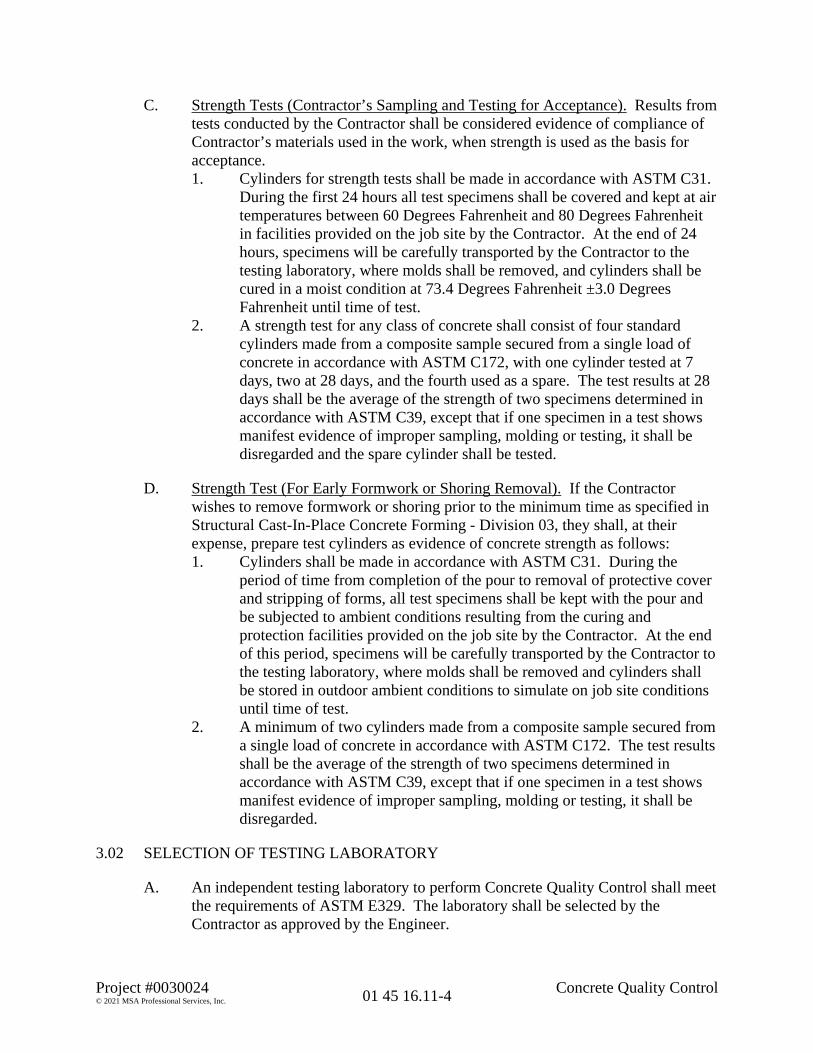
Project #0030024 Concrete Quality Control© 2021 MSA Professional Services, Inc. 01 45 16.11-4
C. Strength Tests (Contractor’s Sampling and Testing for Acceptance). Results fromtests conducted by the Contractor shall be considered evidence of compliance ofContractor’s materials used in the work, when strength is used as the basis foracceptance.1. Cylinders for strength tests shall be made in accordance with ASTM C31.
During the first 24 hours all test specimens shall be covered and kept at airtemperatures between 60 Degrees Fahrenheit and 80 Degrees Fahrenheitin facilities provided on the job site by the Contractor. At the end of 24hours, specimens will be carefully transported by the Contractor to thetesting laboratory, where molds shall be removed, and cylinders shall becured in a moist condition at 73.4 Degrees Fahrenheit ±3.0 DegreesFahrenheit until time of test.
2. A strength test for any class of concrete shall consist of four standardcylinders made from a composite sample secured from a single load ofconcrete in accordance with ASTM C172, with one cylinder tested at 7days, two at 28 days, and the fourth used as a spare. The test results at 28days shall be the average of the strength of two specimens determined inaccordance with ASTM C39, except that if one specimen in a test showsmanifest evidence of improper sampling, molding or testing, it shall bedisregarded and the spare cylinder shall be tested.
D. Strength Test (For Early Formwork or Shoring Removal). If the Contractorwishes to remove formwork or shoring prior to the minimum time as specified inStructural Cast-In-Place Concrete Forming - Division 03, they shall, at theirexpense, prepare test cylinders as evidence of concrete strength as follows:1. Cylinders shall be made in accordance with ASTM C31. During the
period of time from completion of the pour to removal of protective coverand stripping of forms, all test specimens shall be kept with the pour andbe subjected to ambient conditions resulting from the curing andprotection facilities provided on the job site by the Contractor. At the endof this period, specimens will be carefully transported by the Contractor tothe testing laboratory, where molds shall be removed and cylinders shallbe stored in outdoor ambient conditions to simulate on job site conditionsuntil time of test.
2. A minimum of two cylinders made from a composite sample secured froma single load of concrete in accordance with ASTM C172. The test resultsshall be the average of the strength of two specimens determined inaccordance with ASTM C39, except that if one specimen in a test showsmanifest evidence of improper sampling, molding or testing, it shall bedisregarded.
3.02 SELECTION OF TESTING LABORATORY
A. An independent testing laboratory to perform Concrete Quality Control shall meetthe requirements of ASTM E329. The laboratory shall be selected by theContractor as approved by the Engineer.

Project #0030024 Concrete Quality Control© 2021 MSA Professional Services, Inc. 01 45 16.11-5
3.03 TEST REPORTS
A. Test reports will be directly distributed by the laboratory as follows: The originalto the Contractor; two copies to the Engineer; one copy to the Owner.
3.04 TESTING REQUIREMENTS
A. The Contractor shall be required to perform one test for each 100 cubic yards ofconcrete poured, or fraction thereof, for each class of concrete used. Each testshall consist of four (4) cylinders; one (1) to be tested at seven (7) days, two (2) tobe tested at twenty-eight (28) days, and one (1) to be a spare.
B. Compliance testing shall be performed on every single load, or portion thereof,where water addition to the single load, or portion thereof, takes place on site.
C. A minimum of one (1) test shall be performed per day for each class of concreteplaced.
3.05 CONDITIONS OF COMPLIANCE AND NON-COMPLIANCE
A. Compliance of Contractor’s Materials Used in the Work.1. To conform to the requirements of this specification, every 28-day test
representing each mix must be equal to or greater than the specifiedminimum strength without exception. If a specimen shows manifestevidence of improper sampling, molding, or testing, it will be disregarded.Note, however, that the anticipated strength for all mixes is appreciablyabove the specified minimum strength due to quality required by thewater-cement ratio specified.
B. Non-Compliance of Contractor’s Materials Used in the Work1. When strength is used as the basis for acceptance, should individual tests
of the Contractor’s specimens produce strengths less than 90% of thespecified strength (f’c), tests of cores drilled from the area in question maybe required in accordance with ASTM C42. Three cores shall be taken foreach cylinder test less than 90% of the specified strength (f’c). If theconcrete in the structure will be dry under service conditions, the coresshall be air dried (temperature 60 to 80°F, relative humidity less than 60percent) for seven (7) days before test and shall be tested dry. If theconcrete in the structure will be more than superficially wet under serviceconditions, the cores shall be immersed in water for at least 48 hours andtested wet.
2. Concrete represented by the core tests will be considered structurallyadequate and meet the requirements of this specification if the average ofthe three cores is equal to at least 95 percent of the specified strength (f’c)and if no single core is less than 90 percent of f’c. To check testingaccuracy, locations represented by erratic core strengths may be retested.

Project #0030024 Concrete Quality Control© 2021 MSA Professional Services, Inc. 01 45 16.11-6
If these strength acceptance criteria are not met by the core tests, theEngineer shall order appropriate action at no additional cost to the Owner.
END OF SECTION

Apostle Islands Marina Reconstruction TREE AND PLANT PROTECTION00320024
Section 01 56 39 Page 1 of 3
SECTION 01 56 39 - TREE AND PLANT PROTECTION
PART ONE - GENERAL
1.01 QUALITY ASSURANCE
A. Qualifications
1. All assessments or treatment of damaged plants shall be done by a companyspecializing in landscape appraisal and arboriculture.
2. All Contractors shall be approved by the Engineer.
B. All materials and work shall comply with applicable sections of:
1. A Guide for Estimating Value of Trees and Other Plants, Council of Tree andLandscape Appraisers, latest edition.
1.02 DESCRIPTION OF THE WORK
A. The Contractor will provide, erect, maintain, and remove temporary fencing requiredto protect all existing vegetation identified by the Engineer.
B. The Contractor shall confine work to areas within contract limit lines and maintainbarrier fences in good condition throughout the construction of the project.
C. The Contractor will be responsible for any violation as established by this section andshall be subject to the fines as stated in the schedule of fines.
D. Clearing and grubbing shall be limited to those areas shown or identified in the field bythe Engineer. Clearing and grubbing or construction shall not commence beforecompletion and Engineer approval of protective barrier.
1.03 DEFINITIONS
A. Protective Barrier: A fence installed as a temporary device for the purpose ofpreventing unauthorized access during the full period of construction and/or toprotect existing vegetation from damage and disturbance.
B. Damage: Physical change to the site or its vegetation caused by equipment, material,labor, or grading operations which has occurred after a Notice to Proceed has beenissued.
C. Disturbance: Visual change to the site or vegetation caused by equipment, material,labor, or grading operations which has occurred after a Notice to Proceed has beenissued.
D. Trespass: Any encroachment into protected areas caused by equipment, material,labor, or grading operations which has occurred after a Notice to Proceed has beenissued.

Apostle Islands Marina Reconstruction TREE AND PLANT PROTECTION00320024
Section 01 56 39 Page 2 of 3
E. Drip Line: The point where the foliage cover concentrates main water on the ground.This line follows the general configuration of the outermost edge of a tree or shrubformed by its leaves and branches.
F. Existing Vegetation: Any existing tree, shrub, ground cover, wildflower, grass, or weedmass which presently occurs on the site indicated to remain.
G. Protection: Means of protecting existing site features from trespass, damage, ordisturbance by the use of barriers or other means necessary to prevent such trespass,damage, or disturbance.
H. Site: The area as shown on the survey belonging to the Owner including areas whereconstruction occurs or access to the site is granted.
I. Violation: Trespass, disturbance, or damage caused by any construction, delivery, ortransportation vehicle, construction material through storage or usage; solid or liquiddebris; or litter observed by the Engineer who conveys the observed violation to theContractor verbally, if possible, and in writing within 7 days of a violation. The writtennotice shall include the date, the approximate time, the general location, and type ofviolation.
J. Contract Limit Lines: Construction limits defined as shown and as identified in the fieldby the Engineer.
K. Initial Clearing Zone: Area within the construction limit lines, but not areas enclosedby protective barriers.
1.04 SITE CONDITIONS
A. The site and surrounding property presently supports a stand of mature trees. Thesestands are considered key landscape features and are to be preserved and protectedthroughout the work.
B. Clearing, grubbing, and mass grading shall be confined to the initial clearing zone.
1.05 TEMPORARY FENCE
A. Protection: Prior to commencing clearing operations, vegetation to be saved shall beprotected by erecting a barrier in the location indicated and as approved in the field bythe Engineer. The barrier shall be a minimum of 20 feet from each trunk or at the dripline, whichever is greater; or as approved by the Engineer. The barriers shall remain inplace until the Engineer approves their removal.

Apostle Islands Marina Reconstruction TREE AND PLANT PROTECTION00320024
Section 01 56 39 Page 3 of 3
PART TWO - PRODUCTS
2.01 MATERIALS
A. Protection barriers shall be constructed of wood and wire snow fence chain link fabricor orange plastic fence webbing.
B. Fence shall be a minimum of 4 feet in height. Material shall be approved by theEngineer.
C. Fencing shall be strung on 6-foot steel posts set at a maximum spacing of 8 feet centerto center.
PART THREE - EXECUTION
3.01 DAMAGE DETERMINATION
A. Disturbed or damaged trees shall be attended by a tree surgeon approved by theEngineer. All costs incurred shall be paid by the Contractor, and the Contractor shallbe assessed a fine based on a damage appraisal made in accordance with the latestedition of A Guide for Estimating the Value of Trees and Other Plants by an arboristapproved by the Engineer.
B. Trees damaged shall be measured for size of trunk diameter according to the AmericanStandard for Nursery Stock as prepared by the American Association of Nurserymen,Inc.
1. The caliper of the trunk shall be taken 6 inches above ground level for treeslarger than 4 inches, up to and including 12-inch caliper.
2. The caliper of the trunk shall be taken 4 feet, 6 inches above ground level fortrees larger than 12 inches caliper.
END OF SECTION 01 56 39

THIS PAGE INTENTIONALLY LEFT BLANK

Project# 00320024 01 77 00-1Project Closeout
SECTION 01 77 00PART 1 - GENERAL
1.1 Manufacturer's Specifications
A. The installation of manufactured products and equipment, together with allassociated parts, shall be in conformance with the manufacturer'srecommendations, and code requirements. All installations shall be complete andready for immediate use, and every part required for proper operation of themanufacturer's equipment shall be provided. Following the completion of theWork under this Contract, all installed equipment shall be tested for properoperation and compliance with the Contract.
1.2 Final Inspection
A. The Contractor shall request a final inspection in writing at least ten (10) daysprior to the anticipated date of completion.
B. Work will not be considered ready for final inspection until all the Work has beencompleted and the Contractor has certified that all items are properly operatingand in strict compliance with all Contract terms and conditions.
C. The Contractor or the project supervisor shall be at the job site during the finalinspection.
1.3 Tests
A. Complete all tests required to prove actual operating performance of equipmentand systems incorporated into the project.
B. Submit reports of all tests to the Engineer prior to final payment.
C. Provide any regulatory acceptance documents in cases of cleanup.
1.4 Maintenance and Operating Instructions
A. Submit three (3) final copies of all operating, maintenance instructions and partslists for all equipment and systems that require adjustment, servicing, andattention for proper operation. Include all information necessary for properoperation of equipment. Use simple, non-technical language where possible.Provide all necessary diagrams and schematics required by repairmen. Anyhazards likely to occur in operation of equipment shall be pointed out to avoid
Project# 00320024 01 77 00-2Project Closeout
improper operation of any equipment that might result in damage or danger toequipment, building or personnel.
B. Final copies of all maintenance and operating information shall be submitted inbound form as a "Manual of Operating Instructions" with items grouped bysections of Work. Append each manual with name, address, telephone number ofContractor, subcontractor and companies or individuals providing service forequipment used.
C. Provide competent personnel to meet with the Government representative to fullyexplain and familiarize the Government personnel with all equipment and itsoperation and maintenance.
1.5 Record Drawings:
The Contractor shall provide and maintain in proper order and in good, clean condition,at the Research Center office or at the project site, one (1) complete set of full size printsof all Drawings. On this set, with red pencil or ink, the Contractor will neatly inscribe allchanges in Work. At time of final acceptance, and prior to final payment, these correctedprints will be presented to the COR. The Contractor will note all data and changes onthese record drawings in sufficient detail and clarity to provide information necessary forpreparation of "as built" drawings by the Government.
1.6 Guarantees, Warranties and Certificates
A. The Contractor will submit all guarantees, warranties and certificates to theGovernment prior to final payment.
B. The Government requires a 100% warranty for a period of one full year after finalacceptance. Items of Work found defective during the warranty period will bereplaced at no cost to the Government and the warranty for that particular part ofthe Work shall automatically extend for one full year beyond the completion dateof repairs.
C. If a manufacturer or supplier offers a guarantee in excess of the one yearrequirement outlined herein, then the longer guarantee period will apply for thoseparticular items.
PART 2 - PRODUCTS (Not Applicable)
PART 3 - EXECUTION (not Applicable)

Project# 00320024 01 77 00-3Project Closeout
END OF SECTION 01 77 00

THIS PAGE INTENTIONALLY LEFT BLANK
Apostle Islands Marina MAINTENANCE OF EXISTING CONDITIONS00320024
Section 02 01 00 Page 1 of 1
PART ONE GENERAL
1.01 SUMMARY
A. Section Includes requirements for the preservation of the existing conditions at the ApostleIslands Marina. All due care shall be taken to not damage the paving, walks andlandscaping adjacent to work areas.
B. Related Sections
1. 01 56 39 Tree and Plant Protection
2. 02 41 13 Demolition
1.02 SYSTEM DESCRIPTION
A. Apostle Islands Marina is an operating facility with active service and storage workthroughout the year. Contractor shall not inhibit marina operations by blocking orinterfering with day to day work.
B. Contractor shall place materials and structures only in areas designated by marinamanager.
1.03 DELIVERY, STORAGE, AND HANDLING
A. Layout areas shall be only those designated by the marina manager.
B. Contractor shall be responsible for acceptance of material deliveries on site
C. Contractor shall be responsible for storage and protection of delivered materials.
D. Contractor shall be responsible for Waste Management and Disposal.
PART TWO PRODUCTS
None
PART THREE EXECUTION
3.01 EXAMINATION
A. Prior to commencement of construction operations, Contractor shall meet with Engineerand Marina Manager to determine work and laydown areas available.
B. Contractor shall verification site conditions and document areas damaged prior to start ofoperations.
3.02 CLEANING
A. Post construction Contractor shall clean all work and laydown areas to a condition equal orbetter than the pre-construction condition.
3.03 PROTECTION
A. Contractor shall protect all vegetation vulnerable to work related damage.
END OF SECTION 02 01 00

THIS PAGE INTENTIONALLY LEFT BLANK

Project #00320024 Structure Demolition© 2021 MSA Professional Services, Inc. 02 41 16-1
SECTION 02 41 16
STRUCTURE DEMOLITION
PART 1 GENERAL
1.01 APPLICABLE PROVISIONS
A. Applicable provisions of Division 01 shall govern the work of this section.
1.02 APPLICABLE PUBLICATIONS
A. The following publications of the issues listed below, but referred to thereafter by basicdesignation only, form a part of this specification to the extent indicated by thereference thereto.1. American National Standards Institute (ANSI) Specifications and Standards:
a. ANSI A10.6 - Safety Requirements for Demolition, Current Edition.2. Code of Federal Regulations (CFR), Title 29, Chapter XVII - Occupational Safety
and Health Administration (OSHA), Department of Labor, Part 1926 Regulations,Current Edition.
1.03 DESCRIPTION OF WORK
A. The work under this section shall cover furnishing all materials, equipment, tools, laborand supervision necessary to remove equipment, adapt for new equipment, and disposeof unused materials as indicated upon contract drawings and as specified herein.
B. Comply with applicable rules, regulations, codes, and ordinances of local, state, andfederal authorities including ANSI A10.6, Safety Requirements for Demolition.
C. Contractor shall sequence work to enable uninterrupted operation of the facility to theextent of practical limits, and as determined by Engineer.
1.04 RELATED WORK ELSEWHERE
A. Procurement and Contracting Requirements - Division 00 (All Sections)
B. Work Restrictions and Provisions - Division 01
C. Submittals - Division 01
D. Temporary Utilities - Division 01
E. Maintenance of Existing Conditions - Division 02

Project #00320024 Structure Demolition© 2021 MSA Professional Services, Inc. 02 41 16-2
1.05 SUBMITTALS
A. Submit detailed sequence of operation for structure demolition and removal work inaccordance with Submittals - Division 01 of these specifications to ensure minimuminterruptions of Owner’s operations. Submit timeline indicating removal and placementof proposed equipment.
B. Submit detailed information for weather protection, dust protection, openings requiredif any in protection walls, sealing system for perimeter of opening and wall.
C. Submit certificates and/or letters as evidence of discontinuation of services to buildingor structure requiring removal from appropriate agencies and evidence ofdiscontinuation of water or electrical lines used for structure demolition purposes.
PART 2 PRODUCTS
2.01 EQUIPMENT
A. Use normal equipment for structure demolition purposes which meet all safetyrequirements imposed on such equipment.
2.02 REMOVAL OF ITEMS
A. Items noted to be turned over to Owner shall be delivered to location on propertywhere designated by Owner.
B. Refer to contract drawings and 00 21 13 Instructions to Bidders for list items to beremoved.
2.03 ITEMS FOR STORAGE
A. Items noted for storage shall be delivered to location on site at Contractor’s discretionuntil reincorporated into the Work.
PART 3 EXECUTION
3.01 GENERAL
A. Conditions existing at time of inspection for bidding purposes will be maintained by theOwner to the extent practicable. Owner shall have the right to salvage any existingequipment and furnishings.
B. Owner assumes no responsibility for subsurface conditions on site. Become familiarwith subsurface conditions at the site. Owner assumes no responsibility for actualconditions of structures and appurtenances to be demolished. Become familiar withactual condition of structures and appurtenances.

Project #00320024 Structure Demolition© 2021 MSA Professional Services, Inc. 02 41 16-3
C. Perform structure demolition work required in connection with this project with duecare, including shoring and bracing. Be responsible for any damage which may becaused by such work to any part or parts of existing building which is to remain. Wherenecessary to prevent collapse of any construction, install temporary shores, struts, orbracing. Do not commence structure demolition work until all temporary constructionis complete.
3.02 POLLUTION CONTROLS
A. Use water sprinkling, temporary enclosures, and other suitable methods to limit dustand dirt rising and scattering in air to lowest level practical. Clean adjacent structuresand improvements of dust, dirt, and debris caused by structure demolition operations.Return adjacent areas to condition existing prior to start of the work.
B. Comply with governing regulations pertaining to environmental protection.
3.03 BELOW-GRADE DEMOLITION
A. Demolish and remove below-grade wood, metal construction, and floor construction asdirected upon contract drawings. Demolish all abandoned structures to a depth of notless than 24 inches below the existing ground surface, or 24 inches below planned finishgrade, whichever is lower.
B. All abandoned structures or tanks which could hold moisture shall have drain holes cutthrough the bottom, or the structures or tanks shall be otherwise breached to allowmoisture to pass.
C. Cap, with appropriate thrust restraint, all abandoned piping and conduit for a complete,permanent abandonment. Provide thrust restraint with a poured concrete reactionblock in accordance with the contract drawings, or as indicated in Special Procedures -Division 01.
D. Completely fill below-grade areas and voids resulting from demolition. Use satisfactorysoil materials consisting of stone, gravel, and sand, free from debris, trash, frozenmaterials, roots and other organic matter. Prior to placement of fill materials, ensurethat areas to be filled are free of standing water, trash and debris. Place fill materials inhorizontal layers not exceeding 6 inches in loose depth. Compact each layer at optimummoisture content of fill material to a density equal to original adjacent ground, unlesssubsequent excavation for new work is required.
E. Coordinate activities to permit access by other trades required for the work, enablingthem to complete work which is assigned to them. Accomplish all work required bycontract drawings, including work specifically noted plus additional work related tospecific work noted.

Project #00320024 Structure Demolition© 2021 MSA Professional Services, Inc. 02 41 16-4
3.04 SELECTIVE DEMOLITION
A. Demolish masonry and concrete in small sections. Use braces and shores as necessaryto support the structure of the building and protect it from damage. Where limits ofdemolition are exposed in the finish work, cut with saws, providing a straight line,plumb, true, and square.
B. Disconnect services to equipment at unions, flanges, valves, or fittings. Remove and/ordemolish plumbing, mechanical, and electrical components not requiring salvage orreuse. Remove and/or demolish to penetration point at floor, ceiling, and wall orsurface, as applicable. Cut fire electrical systems in such a manner as to insurecontinued operation of the systems in remaining buildings.
C. Leave exposed existing floor, ceiling, and wall or surface in suitable condition forreceiving new finish.
3.05 PROTECTION
A. Make such explorations and probes as necessary to ascertain any required protectionmeasures before proceeding with demolition and removal work. Provide protection forworkmen, public, adjacent construction, and occupants of existing building(s). Provideprotection for adjacent private property. Promptly repair damages caused to adjacentfacilities at no cost to Owner.
B. Provide and maintain adequate catch platforms, warning lights, barricades, guards,weather protection, dust protection, fences, planking, bracing, shoring, piling, signs, andother items required for proper protection.
C. Explosives shall not be used. Use no equipment or methods of operation which willcause damage to adjoining buildings either by direct contact or by transmission.
3.06 UTILITY SERVICES
A. Maintain existing utilities indicated to remain, keep in service, and protect againstdamage during demolition operations.
3.07 DISPOSAL
A. Remove all disposable material and equipment indicated and properly dispose of at off-site location of Contractor’s choice. Storage of disposable materials and equipment onsite shall not be permitted.
B. Burning of debris on site is not permitted.
3.08 RESTORATION
A. Restore the site after demolition operations are complete.

Project #00320024 Structure Demolition© 2021 MSA Professional Services, Inc. 02 41 16-5
B. Restore interior and exterior building surfaces with similar materials and to a conditionequal to or better than previously existed. Refer to the finish schedules of the contractdrawings and specifications for materials and finishes specified.
C. Restore site with similar materials, and to a condition equal to or better than previouslyexisted. Perform grading in accordance with final grading requirements as indicated onthe contract drawings.1. Grading tolerances shall be as indicated in Grading - Division 31.2. Restore turf areas disturbed. Refer to Seeding - Division 32 and Sodding -
Division 32 for specific requirements.3. Restore pavement or sidewalk areas disturbed. Refer to Maintenance of
Existing Conditions - Division 02 for specific requirements.
D. Provide temporary erosion control measures until such time as permanent restorationno longer requires these measures, and as directed by the Engineer.
END OF SECTION

THIS PAGE INTENTIONALLY LEFT BLANK

Project #03200024 Concrete Reinforcing© 2021 MSA Professional Services, Inc. 03 20 00-1
SECTION 03 20 00
CONCRETE REINFORCING
PART 1 GENERAL
1.01 APPLICABLE PROVISIONS
A. Applicable provisions of Division 01 shall govern work of this section.
1.02 APPLICABLE PUBLICATIONS
A. The following publications of the issues listed below, but referred to thereafter bybasic designation only, form a part of this specification to the extent indicated bythe reference thereto.1. American Concrete Institute (ACI) Specifications and Standards:
a. ACI 315 - Manual of Standard Practice for Detailing ReinforcedConcrete Structures, Current Edition.
b. ACI 318 - Building Code Requirements for Structural Concreteand Commentary, Current Edition.
2. American Society for Testing and Materials (ASTM), Annual Book ofASTM Standards:a. ASTM A82 - Standard Specification for Steel Wire, Plain, for
Concrete Reinforcement, Current Edition.b. ASTM A184 - Standard Specification for Welded Deformed Steel
Bar Mats for Concrete Reinforcement, Current Edition.c. ASTM A615 - Standard Specification for Deformed and Plain
Carbon-Steel Bars for Concrete Reinforcement, Current Edition.d. ASTM A1064 - Standard Specification for Carbon-Steel Wire and
Welded Wire Reinforcement, Plan and Deformed, for Concrete,Current Edition.
3. American Welding Society (AWS), Specifications and Standards:a. AWS D12.1 - Welding Reinforcing Steel, Metal Inserts, and
Connections in Reinforced Concrete Construction, Current Edition.4. American Association of State Highway Transportation Officials
(AASHTO), Specifications and Standards:a. AASHTO M182 - Specification for Burlap Cloth Made from Jute
or Kenaf, Current Edition5. Concrete Reinforcing Steel Institute (CRSI) Specifications and Standards:
a. CRSI - Manual of Standard Practice, Current Edition.b. CRSI - Recommended Practice for Placing Reinforcing Bars,
Current Edition.c. CRSI - Recommended Practice for Placing Bar Supports,
Specifications and Nomenclature, Current Edition.d. CRSI - Recommended Practice for Reinforcing Bar Splices,
Current Edition.

Project #03200024 Concrete Reinforcing© 2021 MSA Professional Services, Inc. 03 20 00-2
1.03 DESCRIPTION OF WORK
A. The work under this section shall cover furnishing and installing concretereinforcing as shown on the contract drawings and as specified herein.
1.04 RELATED WORK ELSEWHERE
A. Procurement and Contracting Requirements - Division 00 (All Sections)
B. Concrete Accessories - Division 03
C. Cast-in-Place Concrete - Division 03
1.05 SUBMITTALS
A. Contractor shall submit such product literature and catalog cuts of materials to besupplied to relate these materials to the specification. Information shall be inconformance with requirements of Submittals - Division 01 of thesespecifications.1. Submit detailed reinforcing drawings prepared in accordance with ACI
315, including bar schedule with bar marks and bends indicated.2. Comply with CRSI Manual of Standard Practice showing bar schedules,
stirrup spacing, diagrams of bent bars and arrangements of concretereinforcement. Include special reinforcement required at openingsthrough concrete.
3. Verify dimensions and make proper allowance for fitting together work ofother trades.
B. Submit a certification attesting that reinforcing steel meets the requirements ofASTM A615, including Supplementary Requirements S1, and that welded steelwire fabric meets the requirements of ASTM A1064.1. Submit certified copies of mill reports, tensile and bend tests for
reinforcing steel on projects where the quantity of reinforcing exceeds 15tons.
2. For information only, submit manufacturer’s data and instruction forproprietary items, including reinforcement and accessories.
PART 2 PRODUCTS
2.01 REINFORCEMENT
A. Steel Bar Reinforcement. Main reinforcing and stirrups; ASTM A615, Grade 60.
B. Welded Wire Fabric. Welded wire fabric, flat sheets, ASTM A1064, 6x6-W2.9xW2.9, unless otherwise specified or indicated on the contract drawings.

Project #03200024 Concrete Reinforcing© 2021 MSA Professional Services, Inc. 03 20 00-3
C. Steel Tie Wire. Steel tie wire, ASTM A82, plain, cold-drawn, 16 gauge orheavier.
D. Supports For Reinforcement. Bolsters, chairs, spacers and other devices forspacing, supporting and fastening reinforcement in place complying with CRSIManual of Standard Practice. For slabs on grade where base material will notsupport chairs, use supports with sand plates or horizontal runners to locate meshproperly in slab. Provide hot-dipped galvanized or plastic-coated accessories incontact with forms for sight exposed concrete; stainless steel accessories forsandblasted or bushhammered concrete.
PART 3 EXECUTION
3.01 FABRICATION
A. Fabricate and place to shapes and dimensions indicated or required to carry outintent of contract drawings and these specifications.
B. Bends for stirrups and ties shall be made around a pin having a diameter not lessthan four times the diameter of reinforcing bar. Bends for other bars shall bemade around a pin having a diameter not less than six times diameter of bar,except that for bars larger than 1 inch, pin shall be not less than eight timesdiameter of bar.1. Perform cutting and bending in the shop; bend and cut steel cold. Heating
of reinforcement will not be permitted. Do not bend or straighten bars in amanner that will injure the material.
2. Field bending of bars shall not be allowed without the Engineer’sapproval.
C. Tagging shall be with metal, linen, or rope fiber tags filled in with machine orwaterproof ink. Paper tags shall not be allowed.
D. Reinforcing bars shall conform accurately to the dimensions shown on thecontract drawings.
3.02 PRODUCT DELIVERY, STORAGE AND HANDLING
A. For reinforcing steel fabricated on-site, shop from the mill in bundles, limited toone size and length, tagged with a waterproof tag showing the name of the mill,heat number, grade and size of the bars and identifying number.
B. For reinforcing steel fabricated off-site, deliver in bundles identified as tostructure and shop drawing number. Identify each individual bar with awaterproof tag showing the grade, size and bar mark from the approved barschedule.

Project #03200024 Concrete Reinforcing© 2021 MSA Professional Services, Inc. 03 20 00-4
C. Protect reinforcing steel and wire fabric from damage and from dirt, oil grease,other foreign matter, and rust-causing condition. Do not store reinforcement indirect contact with the ground.
3.03 CLEANING
A. Before placing and before pouring concrete, all reinforcement shall be thoroughlycleaned of all oil, dirt, loose mill scale, loose rust, or foreign matter that willdestroy or reduce bond.
3.04 PLACING REINFORCEMENT
A. Placement. Metal reinforcement shall be accurately placed in accordance withapproved Submittals and adequately secured in position by concrete or metalchairs or spacers. Nails shall not be driven into forms to support reinforcementnor shall wire ties come in contact with forms.
B. Splicing. Lap at splices shall be sufficient to transfer stress between bars by bondand shear.1. Furnish reinforcing bars in full lengths as indicated on the contract
drawings and approved Submittals.2. Do not splice bars unless indicated on the contract drawings or approved
by the Engineer in writing. When authorized, make splices in accordancewith ACI 318; perform welding in accordance with AWS D12.1.
3. Splices generally shall be avoided at points of maximum stress. Minimumsplice lap for stressed bars shall be forty times bar diameter.
C. Offsets in longitudinal bars at change of cross section shall be placed in region oflateral support. Slope of inclined portion of offset shall not be more than one insix and, in tied columns, ties shall be spaced not over 3 inches on centers for adistance of 1 foot below actual point of offset.
D. Embedded Items. The Contractor shall provide for the installation of all itemsembedded in the concrete, such as coil rod inserts, anchor bolts, dowels, etc., asshown on the contract drawings or as provided for in other Divisions of thesespecifications.1. All dowel bars shall be tied securely in place before pouring concrete.2. Provide for clearances with appurtenant materials and devices.
E. Drilled and Grouted or Epoxy Dowel Installation. Existing concrete which willbe incorporated into new work and requiring integration with new concrete willbe doweled as indicated on the contract drawings and as follows:1. Drill hole in existing concrete of size that is 3/4 inch larger in diameter
than diameter of dowel bar. Incline the hole in the concrete such that thenon-shrink grouting or epoxy will be retained in the hole.
2. Fill hole with non-shrink grouting or epoxy.3. Immediately place dowel bar into hole.

Project #03200024 Concrete Reinforcing© 2021 MSA Professional Services, Inc. 03 20 00-5
4. Allow grout or epoxy to take initial set before disturbing dowel bar.
F. Steel Reinforcing Fabric. Reinforce as detailed on the contract drawings; andwhere not indicated, reinforce with wire fabric, place 2 inches from the top of theslab.1. Flat sheets shall be used whenever available. Wire fabric shall lap 6
inches on side joints and 12 inches on end joints. Properly secure withannealed wire. Fabric shall be raised and secured in the correct locationusing permanent supports. Raising the fabric by hook during placement ofconcrete shall NOT be permitted.
2. Alternately, in tight quarters and around appurtenances and openings, lapmesh reinforcement not less than one mesh space plus 2 inches, and tie.
G. Concrete Cover. The minimum cover of concrete for all reinforcement shallconform to the dimensions indicated on the contract drawings, which indicate theclear distance from the edge and end of the reinforcement to the face of theconcrete surface. Provide clearance and spacing indicated on the contractdrawings and approved Submittals, where so indicated.1. Where no clearances are indicated, the thickness of the concrete cover
over reinforcement shall be as follows:a. Concrete cast against and permanently exposed to earth - 3 inches;b. Formed concrete exposed to earth or weather - 2 inches;c. Formed concrete not exposed to earth or weather - 1-1/2 inches;d. Slabs not exposed to earth or weather - 1 inch.
END OF SECTION

THIS PAGE INTENTIONALLY LEFT BLANK

Project #00320024 Cast-in-Place Concrete© 2021 MSA Professional Services, Inc. 03 30 00-1
SECTION 03 30 00
CAST-IN-PLACE CONCRETE
PART 1 GENERAL
1.01 APPLICABLE PROVISIONS
A. Applicable provisions of Division 01 shall govern work of this section.
1.02 APPLICABLE PUBLICATIONS
A. The following publications of the issues listed below, but referred to thereafter bybasic designation only, form a part of this specification to the extent indicated bythe reference thereto.1. American Concrete Institute (ACI), Annual Book of ACI Standards:
a. ACI 117/177R - Standard Specification for Tolerances forConcrete Construction and Materials and Commentary, CurrentEdition.
b. ACI 211.1 - Standard Practice for Selecting Proportions forNormal, Heavyweight, and Mass Concrete, Current Edition.
c. ACI 209.1R - Report on Factors Affecting Shrinkage and Creep ofHardened Concrete, Current Edition.
d. ACI 301 - Specification for Structural Concrete, Current Edition.e. ACI 302.1R - Guide for Concrete Floor and Slab Construction,
Current Edition.f. ACI 304R - Guide for Measuring, Mixing, Transporting, and
Placing Concrete, Current Edition.g. ACI 305R - Hot Weather Concreting, Current Edition.h. ACI 306.1 (R2002) - Standard Specification for Cold Weather
Concreting, Current Edition.i. ACI 308R - Guide to Curing Concrete, Current Edition.j. ACI 309R - Guide for Consolidation of Concrete, Current Edition.k. ACI 311.4R - Guide for Concrete Inspection, Current Edition.l. ACI 318/318R - Building Code Requirements for Structural
Concrete and Commentary, Current Edition.m. ACI 530/530.1/530R/530.1R - Building Code Requirements for
Commentary for Masonry Structures and Specification forMasonry Structures and Related Commentaries, Current Edition.
n. ACI ASCC-1(05) - The Contractor’s Guide to Quality ConcreteConstruction, Third Edition.
o. ACI CP-10/PACK - Craftsman Study Package for ACICertification of Concrete Flatwork Technician/Finisher, CurrentEdition.
p. ACI MCP06 - ACI Manual of Concrete Practice, Parts 1 through 6,and Index, 2006 Edition.
q. ACI SCM-24 - Concrete Repair Basics, Current Edition.

Project #00320024 Cast-in-Place Concrete© 2021 MSA Professional Services, Inc. 03 30 00-2
r. ACI SP4 - Formwork for Concrete, Current Edition.s. ACI SP15 - Field Reference Manual: Standard Specifications for
Structural Concrete ACI 301 with Selected ACI Reference,Current Edition.
t. ACI SP-71 - ASTM Standards in ACI 318, Current Edition.2. American Society for Testing and Materials (ASTM), Annual Book of
ASTM Standards:a. ASTM C33 - Standard Specification for Concrete Aggregates,
Current Edition.b. ASTM C70 - Standard Test Method for Surface Moisture in Fine
Aggregate, Current Edition.c. ASTM C94 - Standard Specification for Ready-Mixed Concrete,
Current Edition.d. ASTM C109 - Standard Test Method for Compressive Strength of
Hydraulic Cement Mortars (using 2-inch or [50 mm] CubeSpecimens), Current Edition.
e. ASTM C125 - Standard Terminology Relating to Concrete andConcrete Aggregates, Current Edition.
f. ASTM C127 - Standard Test Method for Density, Relative Density(Specific Gravity) and Absorption of Coarse Aggregate, CurrentEdition.
g. ASTM C128 - Standard Test Method for Density, Relative Density(Specific Gravity) and Absorption of Fine Aggregate, CurrentEdition.
h. ASTM C131 - Standard Test Method for Resistance toDegradation of Small-Size Coarse Aggregate by Abrasion andImpact in the Los Angeles Machine, Current Edition.
i. ASTM C143 - Standard Test Method for Slump of Hydraulic-Cement Concrete, Current Edition.
j. ASTM C150 - Standard Specification for Portland Cement,Current Edition.
k. ASTM C171 - Standard Specification for Sheet Materials forCuring Concrete, Current Edition.
l. ASTM C191 - Standard Test Methods for Time Setting ofHydraulic Cement by Vicat Needle, Current Edition.
m. ASTM C219 - Standard Terminology Relating to HydraulicCement, Current Edition.
n. ASTM C226 - Standard Specification for Air-Entraining Additionsfor Use in the Manufacture of Air-Entraining Hydraulic Cement,Current Edition.
o. ASTM C233 - Standard Test Method for Air-EntrainingAdmixtures in Concrete, Current Edition.
p. ASTM C260 - Standard Specification for Air-EntrainingAdmixtures for Concrete, Current Edition.

Project #00320024 Cast-in-Place Concrete© 2021 MSA Professional Services, Inc. 03 30 00-3
q. ASTM C311 - Standard Test Methods for Sampling and TestingFly Ash or Natural Pozzolans for use as a Mineral Admixture inPortland-Cement Concrete, Current Edition.
r. ASTM C309 - Standard Specification for Liquid Membrane-Forming Compounds for Curing Concrete, Current Edition.
s. ASTM C494 - Standard Specification for Chemical Admixtures forConcrete, Current Edition.
t. ASTM C535 - Standard Test Method for Resistance toDegradation of Large-Size Coarse Aggregate by Abrasion andImpact in the Los Angeles Machine, Current Edition.
u. ASTM C566 - Standard Test Method for Total EvaporableMoisture Content of Aggregate by Drying, Current Edition.
v. ASTM C595 - Standard Specification for Blended HydraulicCement, Current Edition.
w. ASTM C618 - Standard Specification for Coal Fly Ash and Raw orCalcined Natural Pozzlan for Use in Concrete, Current Edition.
x. ASTM C688 - Standard Specification for Functional Additions forUse in Hydraulic Cements, Current Edition.
y. ASTM C989 - Standard Specification for Slag Cement for Use inCement and Mortars, current edition.
3. Portland Cement Association (PCA) Standards and Specifications:a. PCA - Design and Control of Concrete Mixtures, Current Edition.
1.03 DESCRIPTION OF WORK
A. The work covered under this section shall cover furnishing all materials,equipment and labor required to construct all cast-in-place concrete as shown onthe contract drawings and as specified.
1.04 RELATED WORK ELSEWHERE
A. Procurement and Contracting Requirements - Division 00 (All Sections)
B. Submittals - Division 01
C. Concrete Quality Control - Division 01
D. Structural Cast-in-Place Concrete Forming - Division 03
E. Concrete Accessories - Division 03
F. Concrete Reinforcing - Division 03
1.05 SUBMITTALS
A. Submit such product literature and catalog cuts of materials to be supplied torelate these materials to the specification. Information shall be in conformancewith requirements of Submittals - Division 01 of these specifications.

Project #00320024 Cast-in-Place Concrete© 2021 MSA Professional Services, Inc. 03 30 00-4
B. Concrete Design Mix1. Prior to the start of placing of concrete, submit the design mix for each
class of concrete, indicating that the concrete constituents and proportionswill result in a concrete mix meeting the physical requirements for eachclass of concrete specified. Submit with the design mix, laboratory testreports and manufacturer’s certificates attesting the conformance ofconstituents with these specifications.
2. Do not vary the proportions of the constituents or source of material of theapproved mix without submitting corresponding test result documentationto the Engineer for review and approval.
3. Design mix shall indicate proportions of cement, aggregate and water, andnames and proportions of admixtures and air-entraining agents.
4. Provide certification that the design mix complies with all ACI and ASTMrequirements.
1.06 OPERATION/MAINTENANCE MANUALS AND INSTRUCTIONS (NONE)
PART 2 PRODUCTS
2.01 CEMENT
A. Cement shall be Portland Cement ASTM C150 Type I or IA, except as otherwisenoted or approved. Type III cement shall only be used for Class L concrete, orwhen approved by the Engineer.
B. A singular brand and manufacturer of cement shall be used for the entire work.
2.02 FLY ASH
A. Fly ash shall conform to ASTM C618 Class C.
B. A singular source of fly ash shall be used for the entire work.
2.03 SLAG
A. Slag shall be ground granulated blast furnace slag conforming to ASTM C989.
2.04 AGGREGATE
A. Aggregate shall consist of clean, hard durable sand, gravel, crushed gravel orcrushed rock.
B. Aggregate shall conform to the requirements of ASTM C33. Fine and coarseaggregate shall meet ASTM C33 grading requirements. Coarse aggregates shallbe graded in accordance with ASTM gradations as follows:1. 3/4 inch maximum coarse aggregate - ASTM No. 672. 1-1/2 inch maximum coarse aggregate - ASTM No. 4

Project #00320024 Cast-in-Place Concrete© 2021 MSA Professional Services, Inc. 03 30 00-5
C. Maximum aggregate size shall be as defined in the Concrete Schedule, or wherenot defined in the Concrete Schedule, as defined by dimensional constraints forcast-in-place concrete as follows.1. Not larger than one-fifth of the narrowest dimension between sides of the
forms;2. Not larger than one-third the thickness of the slab;3. Not larger than three-fourths of the minimum clear spacing between
individual reinforcing bars or wire, bundles of bars, or prestressingtendons or ducts.
2.05 MIXING WATER
A. Mixing water shall be natural or treated water, clean and free from injuriousamount of oil, acid, alkali, chlorides and sulfates, other common salts, organicmatter or other deleterious substances.
B. Mixing water shall yield cement paste complying with the requirements ASTMC109 and ASTM C191.
2.06 ADMIXTURES
A. All admixtures are subject to the written approval of the Engineer and shall beused in strict accordance with the manufacturer’s recommendations.1. Air-Entraining Admixture
a. All concrete exposed to weather and freeze-thaw cycles shall beair-entrained, unless otherwise specified.
b. Air-Entraining admixture shall conform to ASTM C260.c. Air-Entrainment shall be as indicated for each class as in the
Concrete Schedule.2. Water-Reducing, Set-Controlling Admixtures
a. Water-Reducing, Set-Controlling admixtures shall conform toASTM C494, Type A for water-reducing, Type C for accelerating,Type D for water-reducing and retarding, and Type E forwater-reducing and accelerating.
B. Admixtures containing calcium chloride or soluble chloride shall not be used.
2.07 CURING AND SEALING COMPOUND - INTERIOR
A. Membrane-forming curing compound shall meet the moisture retentionrequirements of ASTM C309, Type 1. Kure 200W, Sonneborn Division ofBASF; Sealtight CS-309 Curing and Sealing Compound, W.R. Meadows, Inc.;Eucocure, Euclid Chemical Co.; or equal.
B. Shall be compatible with surface finish.

Project #00320024 Cast-in-Place Concrete© 2021 MSA Professional Services, Inc. 03 30 00-6
2.08 CURING COMPOUND - EXTERIOR
A. Curing compound shall comply with ASTM C309, Type 2; resin, whitepigmented.
PART 3 EXECUTION
3.01 COORDINATION
A. Examine the drawings and specifications for work of other sections or othercontractors and coordinate such work with the requirements of this Section; makeprovisions for installation of such items as sleeves, pipes, conduits, inserts andhangers in a manner that will not impair or weaken concrete construction.
3.02 READI-MIX CONCRETE
A. Acceptability and Use. Readi-mix concrete shall be designed on the basis ofstrength, durability, impermeability, and exposure condition, as required for theintended use of the structure by methods specified in ACI 211.1 and ACI 318.All readi-mix concrete shall comply with the water-cement ratio for each specificclass of concrete as specified in the Concrete Schedule. Concrete design mix,complete with sample test results shall be submitted to the Engineer for approvalprior to placing any concrete.1. Failure to Meet Strength Requirements. Failure to meet strength
requirements shall be as defined in Concrete Quality Control- Division 01of these specifications.
2. Watertight Concrete. All concrete exposed to earth or water shall bewatertight, shall have a water-cement ratio as specified, and shall be air-entrained as specified in the Concrete Schedule.a. Construct keyways as indicated on the contract drawings.b. Provide damp-proofing membrane as indicated on the contract
drawings.3. Waterproof Concrete. All concrete for water retaining structures shall be
waterproof, shall have a water-cement ratio as specified, and shall be air-entrained as specified in the Concrete Schedule.a. Construct keyways and waterstops as indicated on the contract
drawings.
B. Mix Proportioning. Mix proportioning shall be the responsibility of theContractor and shall be submitted for review and approval by the Engineer, inaccordance with these specifications.1. Select proportions for concrete to obtain the quality requirements for the
class of concrete as specified in the Concrete Schedule. Contractor, attheir expense, shall have an approved independent laboratory preparedesign mixes for each specified concrete class.
2. Slump. Slump for class of concrete shall be as specified in the ConcreteSchedule. The Contractor shall at their expense, make field slump tests in

Project #00320024 Cast-in-Place Concrete© 2021 MSA Professional Services, Inc. 03 30 00-7
accordance with ASTM C143 and Concrete Quality Control-Division 01of these specifications.
3. Adjustment to Concrete Mixes. Design mix adjustments may be requestedby the Contractor when characteristics of materials, conditions, weather,test results, or other circumstances warrant. Laboratory test data forrevised design mixes and strength results shall be submitted and approvedbefore using in the work. No change in contract price will be allowed forthese changes.
4. Addition of Water to the Batch. Addition of water to the batch deliveredto the site shall be in strict accordance with ASTM C94. This shall be theContractor’s responsibility and by their direction, following consultationwith the Engineer.a. Addition of water to the batch shall be one time only. Total
gallons of water added to the batch shall be recorded on the loadticket, which shall be supplied to the Engineer prior to that deliverytruck leaving the site. If water is permitted to be added to mixedconcrete upon arrival at the job, an additional mixing of 30revolutions of the drum shall be required.
b. Contractor shall adjust the water-cement ratio of the batch to thecorresponding value based on the addition of water to the batchand shall submit this information to the Engineer with adjustedstrength data for the final batch proportion.
c. At no time shall the addition of water cause the water-cement ratiospecified in the concrete class schedule to be exceeded.
3.03 GENERAL
A. Unless otherwise specified, conform to ACI 304, 305, and 306 for concreteinstallation requirements such as preparation, mixing, conveying, depositing,curing, and cold and hot weather requirements; consolidate concrete inaccordance with ACI 309.
B. Concrete not placed within 90 minutes or 300 revolutions, whichever occurs first,after the first mixing of the cement and aggregates will be rejected.
C. Contractor shall indicate on record set of Drawings at site, for review prior toinstallation, a pouring program for concrete work showing unit of operation,method of pouring, installation of construction/control joints, expansion joints andall necessary work.
D. Proper grade marker or stakes shall be used by Contractor to establish grades forramps, platforms, sidewalks, slopes to drains, inlets, etc.
E. Trenches, forms, conveying equipment shall be prepared to receive concrete inaccordance with ACI 304.

Project #00320024 Cast-in-Place Concrete© 2021 MSA Professional Services, Inc. 03 30 00-8
F. Place concrete footings upon undistributed clean surfaces, free from frost, ice,mud and water; when foundation is on dry soil or pervious material, laywaterproof sheathing paper over earth surfaces to receive concrete.
G. Rock surfaces upon which concrete is to be placed, make level, clean, free fromall objectionable coatings, water, mud, debris, loose semi-detached or unsoundfragments; level surfaces to receive sand cushion placed to minimum thickness of2 inches.
H. Immediately after placement, protect concrete from premature drying, excessivelyhot or cold temperature and mechanical injury; maintain with minimum moistureloss and relatively constant temperature for the period necessary for hydration ofthe cement and hardening of the concrete.
I. All freshly cast concrete shall be protected from damaging effects of the elementsfreezing, rapid drop in temperature and loss of moisture and from futureconstruction operations.
3.04 PREPARATION OF EQUIPMENT AND PLACE OF DEPOSIT
A. Before placement, clean equipment for mixing and transporting the concrete;remove debris and ice from all surfaces upon which concrete is placed; cleanreinforcement of dirt, loose rust, and mill scale, or other coatings.
B. Remove water from all areas before depositing concrete; before depositing newconcrete on or against concrete that has set, thoroughly roughen; clean existingsurfaces of laitance, foreign matter or loose particles; retighten forms; slushexisting surfaces with neat cement grout coat; place new concrete before grout hasattained initial set; give horizontal construction joints grout brush coat of cement,fine aggregate, in same proportions as concrete to be placed.
C. Thoroughly wet the stone base on which slabs are to be placed where no vaporbarrier is indicated.
D. Check compaction of fill and proper grade for slabs-on-grade. Check screeds andexercise care to prevent disturbing screeds during placement. Provide forconstruction joints in slabs-on-grade at 20 feet maximum in each direction unlessshown otherwise on the contract drawings. Place expansion joint material atjunctures of slabs-on-grade with vertical walls and as otherwise shown.
E. Remove debris, excess form oil, and water from formwork; avoid washing newlydeposited concrete.
3.05 MIXING
A. Ready-mixed concrete shall be mixed and delivered in accordance with ASTMC94 and ACI 304. The production facilities shall comply with the requirementsof the National Ready Mixed Concrete Association Certification Plan as regards

Project #00320024 Cast-in-Place Concrete© 2021 MSA Professional Services, Inc. 03 30 00-9
materials storage and handling, batching equipment, central mixer, truck mixers,agitators, non-agitating units, ticketing system, etc.
B. Do not over-mix; do not use concrete which is retained in mixers so long as torequire additional water in excess of design mix water to permit satisfactoryplacing; retempering of mix is not permitted.
C. Concrete shall be delivered to the site of the work and the mixed concretedischarged completely within 1-1/2 hours after water has been added to cement.In hot weather, or under conditions contributing to quick stiffening of concrete,this time may be reduced by the Engineer.
D. Concrete delivered shall arrive at the site having a temperature not less than50 Degrees F nor greater than 85 Degrees F, unless otherwise permitted by theEngineer.
3.06 CONVEYING
A. Convey concrete from the mixer to the final deposit by methods that will preventsegregation or loss of materials.
B. Use of aluminum conveyances is not permitted.
3.07 CONCRETE PLACEMENT
A. Place concrete, including drops greater than 60 inches using recommendedpractices in accordance with ACI 304 and ACI 318. Once pouring operationcommences, it shall be carried out as a continuous operation until a section iscompleted.
B. Deposit concrete as nearly as practical in its final position to avoid segregationdue to rehandling or flowing; do not use vibrators to move concrete horizontallywithin the forms.
C. Do not use retempered concrete or concrete contaminated by foreign material.
D. Plan and conduct concrete placement to insure that the concrete is kept plastic andthat the concrete is free of cold joints.
E. Where there is a time delay greater than 45-minutes between adjacent concreteplacement, a bulkhead construction joint, complete with waterstops whererequired, must be installed.
F. Do not commence placing when the sun, heat, wind or limitations of facilitiesprovided prevent proper finishing or curing.
G. Discontinue concreting when the descending natural air temperature falls lowerthan 40 Degrees Fahrenheit unless preparations are made and in place to heat or

Project #00320024 Cast-in-Place Concrete© 2021 MSA Professional Services, Inc. 03 30 00-10
insulate concrete in accordance with the cold weather concreting requirements ofthis specification.
H. Concrete for walls shall be deposited in approximately horizontal layers not toexceed 18 inches in height to avoid segregation due to rehandling and flowing.
I. Concrete shall not be placed or poured in water. Water level shall be removed orlowered in a manner approved by Engineer. Excess water shall not be permitted.Powdering a mixture of cement to absorb excess water shall not be permitted.
J. Concrete shall be placed before initial set has occurred. Placing should be carriedon in such manner that the concrete in the form is still plastic and can beintegrated with fresh concrete.
K. Contractor shall notify Engineer of concrete pouring schedule one day in advanceof pour to allow for inspection of reinforcing and forms.
L. Bottom dump buckets may be used for transporting mixed concrete to the desiredlocation. Particular care shall be taken to avoid jarring or bumping as this maycause segregation.
M. Where chutes are used to transport concrete, they shall be of metal or wood withmetal lining and should have a slope not exceeding 1 vertical to 2 horizontal andnot less than 1 vertical to 3 horizontal so that the concrete will travel fast enoughto keep the chute clean but slow enough to avoid segregation of materials. Theend of each chute shall be provided with a baffle to help prevent segregation, orthe concrete should be discharged through a tremie or elephant trunk directly intothe form.
N. Elephant trunks and/or tremies shall be used in walls and columns to prevent freefall of the concrete and to allow the concrete to be placed through the cage ofreinforcing steel.
O. Pumping equipment shall be of suitable type, without Y-sections, and withadequate pumping capacity. Loss of slump in pumping shall not exceed 1-1/2inches.
3.08 CONSOLIDATION
A. Each concrete layer placed shall be compacted by mechanical internal vibratingequipment supplemented by hand spading, rodding, or tamping.
B. The period of concrete vibration shall not be less than two seconds nor more thanfive seconds at any one point.
C. Consolidate concrete thoroughly as it is placed in order to secure a dense mass;work concrete well around the reinforcement and embedded items and into thecorners of the forms.

Project #00320024 Cast-in-Place Concrete© 2021 MSA Professional Services, Inc. 03 30 00-11
D. Use internal vibrators inserted vertically over the entire area of the placement;form vibrators not permitted; internal vibrators shall maintain a minimum of 5000impulses when submerged in concrete.
E. Vibrate until voids are eliminated, coarse aggregate is suspended in mortar, andentrapped air bubbles begin to rise to the surface; concrete should move back intothe space vacated by the vibrator; vibration duration shall be limited only to thetime necessary to produce consolidation without causing segregation.
F. Space vibrator insertions such that the area visibly affected by the vibratoroverlaps the adjacent just-vibrated area by a few inches.
G. Penetrate at least 6 inches into previously placed layers in order to bond betweenlayers and avoid cold joints.
H. Take care not to over-vibrate air entrained concrete; place vibrator to eliminatehoneycombing but avoid excess vibrating that bleeds all entrapped air from themix.
I. Do not use vibrators to transport concrete.
3.09 JOINTS AND KEYWAYS
A. Construct expansion, control, and isolation joints and keyways only whereindicated on the drawings or at additional locations approved by the Engineer(and as shown on the Standard Details).
B. Where the placing of concrete is discontinued, clean off laitance and otherobjectionable material to a sufficient depth to expose sound concrete as soon asconcrete is firm enough to retain its form; smooth the top surface of concreteadjacent to the forms with a trowel to minimize visible joints on exposed faces.
C. Immediately upon completion of the work of placing concrete, removeaccumulations splashed upon the reinforcement and the surfaces of the forms;perform this removal before concrete takes its initial set; clean reinforcing steelcarefully to prevent damage to the concrete steel bond.
D. Do not halt work within 18 inches of the top of any face.
E. For bonded horizontal joint construction, roughen the surface and expose theaggregate; clean the surface thoroughly by wet sandblasting, by cutting with high-pressure water jet or by other approved methods; perform cleaning after theconcrete has hardened to prevent raveling of the surface below the desired depth.
F. Before bonding concrete is placed, clean the surface of loose or soft particles orother objectionable materials and keep wet for a minimum period of 12 hours.

Project #00320024 Cast-in-Place Concrete© 2021 MSA Professional Services, Inc. 03 30 00-12
G. Cover the cleaned and saturated surface with a coating of neat cement grout anddeposit new concrete before the grout has attained its initial set.
3.10 CURING
A. Concrete shall be wet cured by immersion of moisture-retaining covers inconformance with ACI 308 or shall receive curing compound in accordance withACI 309.
B. Water curing is the preferred method of protection for curing concrete other thanunder hot weather conditions; cover exposed surfaces with a saturated material(burlap or cotton mats) and keep wet continuously with a soil soaker hose for 7curing days for all concrete except high early strength concrete; leave covering inplace, without wetting, for an additional 3 days.
C. A curing day is defined as 24-hour day when the concrete surfaces are kept moistand the uniform temperature of the concrete mass is between 55 DegreesFahrenheit and 75 Degrees Fahrenheit.
D. Curing shall start as soon as free surface water disappears after finishing. Whereforms are not removed immediately, curing shall be accomplished in a manneracceptable to the Engineer.
E. Curing compounds may not be used on surfaces that are to receive additionalconcrete, paint or tile.
F. Curing and sealing compound shall not be applied to steel reinforcing anchors,water stops, construction joints, or surfaces to be bonded to other concrete.
G. When using a curing compound, keep surfaces moist after the forms are removed,and the form tie holes repaired; after the surfaces are finished, apply the curingcompound according to the manufacturer’s recommendations; remove forms onlyas required to advance repair of tie holes and minor defects.
H. Slabs: Immediately following slab finishing, apply liquid membrane-formingcuring compound or begin water curing before the surface becomes dry.
I. Vertical Surfaces: When the forms are removed entirely, spray the surface withwater and allow it to reach a uniformly damp appearance with no free water onthe surface; apply curing compound or begin water curing.
J. For curing concrete under hot weather conditions, see Hot Weather Requirementsin this section.
K. For curing concrete under cold weather conditions, see Cold WeatherRequirements in this section.

Project #00320024 Cast-in-Place Concrete© 2021 MSA Professional Services, Inc. 03 30 00-13
3.11 CONCRETE WALL FINISHES
A. Complete screeding and darbying of top of walls before excess moisture orbleeding water is present on the surface.
B. Do not begin subsequent finishing operations until surface water has disappeared.
C. Refer to Concrete Schedule, included in this specification section, for finish typeat each location, defined as follows:1. Rough Form Finish: (Type W1)
a. No form facing materials specified.b. Patch tie holes and defects.c. Chip off fins 1/4 inch or more in height.
2. Smooth Form Finish: (Type W2)a. Use a form facing material that will produce a smooth, hard,
uniform texture on the concrete.b. Keep seams to a practical minimum.c. Patch tie holes and defects.d. Remove all fins.
3. Smooth Rubbed Finish: (Type W3)a. Produce a Smooth Form Finish.b. Wet surface and rub with a Carborundum brick until uniform color
and texture are produced.c. Perform rubbing no later than 24 hours after forms are removed.d. Do not use any cement grout other than the paste drawn from the
concrete itself by rubbing.e. Thoroughly wash the surface with water.
4. Smooth Troweled Finish: (Type W4)a. Produce a Smooth Rubbed Finish.b. After wet-rubbing, finish with a steel trowel to increase
compaction of fines and to provide maximum density.5. Smooth Finish (Grout Cleaned): (Type W5)
a. Use for architectural surfaces exposed to general view, unless otherindicated.
b. Mix 1 part portland cement and 1-1/2 parts fine sand withsufficient water to produce grout having consistency of thick paint;use white portland cement in combination with normal portlandcement to achieve uniform surface color after drying.
c. Wet surface of concrete and uniformly apply grout with brush orspray gun completely filling air bubbles; surface with a wood floatscouring wall vigorously.
d. Allow grout to partially set for one to two hours, depending onweather conditions; in hot dry weather, keep damp, using fine fogspray.
e. When grout has hardened sufficiently to be scraped from wall withedge of steel trowel without removing grout from small air holes,cut off all grout that can be removed with trowel.

Project #00320024 Cast-in-Place Concrete© 2021 MSA Professional Services, Inc. 03 30 00-14
f. Allow surface to dry thoroughly then rub vigorously with dryburlap to completely remove dried grout; there shall be no visiblefilm or grout remaining after this rubbing.
g. The entire cleaning operation for any area must be completed theday it is started; no grout shall be left on overnight, and sufficienttime shall be allowed for grout to dry after it has been cut withtrowel so it can be wiped off clean with burlap.
h. After entire surface has been grout cleaned, wipe off any slightlydark spots or streaks with fine abrasive hone.
3.12 CONCRETE SLAB FINISHING
A. Complete screeding and darbying slabs before excess moisture or bleeding wateris present on the surface.
B. Do not begin subsequent finishing operations until surface water has disappearedand the concrete will sustain foot pressure with only approximately 1/4 inchindentation.
C. Refer to Concrete Schedule, included in this specification section, for finish typeat each location, defined as follows:1. Smooth Float Finish: (Type S1)
a. Consolidate concrete with a power-driven disc-type float or acombination floating-troweling machine with metal float shoesattached.
b. Machines which have a water attachment for wetting the concreteduring the finishing operation are prohibited.
c. Check and level surface plane to a tolerance not exceeding 1/4 inchin 10 feet when tested with a 10-foot straightedge. Cut down highspots and fill low spots; immediately after re-leveling, refloatsurface to a uniform, smooth, granular texture.
d. Where slab drainage is indicated, take care to maintain accurateslopes for drainage.
2. Steel Troweled Finish: (Type S2)a. Produce a Smooth Float Finish.b. After float finishing, steel trowel surface as specified in Concrete
Schedule to increase the compaction of fines and to providemaximum density and wear resistance.
c. Steel Troweled Finish: Screed and bull float or darby. Givepreliminary float finish, true, even and free from depressions; floatsurface with hand or machine floats; compact surface with not lessthan 2 thorough and complete steel troweling operations.
d. Tolerance on finished steel troweled floors in no instance shallexceed 1/8 inch in 10’-0” on surface; where floor drains occur,slope floors to drains.

Project #00320024 Cast-in-Place Concrete© 2021 MSA Professional Services, Inc. 03 30 00-15
e. Buffing: After concrete floors have been properly cured, buffthoroughly to remove soluble salt incrustation or other foreignsubstances.
3. Integral Finishes: (Type S3)a. Use for slabs where some material other than concrete will be the
final wearing surface.b. Screeded Finish - Place screed blocks at frequent intervals and
strike off to surface elevations desired; unless otherwise indicated,use on base slabs upon which grout finish, regular mortar bedceramic tile, sand cushion terrazzo or similar type wearing surfaceis applied.
4. Broom Finish: (Type S4)a. Draw stiff broom over previous Smooth Float Finish, to obtain
non-slip finish.5. Abrasive Aggregate Non-slip Finish: (Type S5)
a. Screed and float concrete to the required finish level with nocoarse aggregate visible.
b. Uniformly sprinkle abrasive aggregate over the floated surface at arate of not less than 1/4-pound per square foot.
c. Steel trowel surface to a smooth even finish, uniform in texture andappearance and free from blemishes, including trowel marks.
d. Immediately after curing remove cement coating covering theabrasive aggregate by steel brushing, rubbing with an abrasivestone or sandblasting to expose abrasive particles.
6. Hardener Floor Treatment: (Type S6)a. Hardener shall be installed in strict accordance with
manufacturer’s printed instructions; experienced workmen shallapply hardener at a minimum of 45 pounds per 100 square feet.
3.13 CONCRETE SIDEWALKS
A. Concrete sidewalk construction shall be as specified in Concrete Sidewalks,Steps, Driveways and Retaining Walls - Division 32 of these specifications.
3.14 CONCRETE CURB AND GUTTER
A. Concrete curb and gutter construction shall be as specified in Concrete Curb andGutter - Division 32 of these specifications.
3.15 CONCRETE WHEEL BUMPER BLOCKS
A. Shall be reinforced precast concrete, minimum 4000 psi, with air entrainment;maximum height 6 inches; install where indicated on Drawings.
3.16 CONCRETE SPLASH BLOCKS
A. Reinforced precast concrete splash blocks formed of 4000 psi concrete with airentrained concrete; shall be 2 inches thick x 1’-0” wide x 2’-6” long; front shall

Project #00320024 Cast-in-Place Concrete© 2021 MSA Professional Services, Inc. 03 30 00-16
be turned up 4 inches for 6 inches overall height; upper corners of turned up lipshall be cut off at 45 Degree angle; wire mesh reinforcing turned up in front lip.
3.17 CONCRETE FILL FOR COMPOSITE FLOOR DECK
A. Fill over composite floor deck shall be lightweight aggregate concrete; noadmixtures containing chloride salts or other deleterious materials shall be used;lightweight concrete shall not exceed 100 pcf weight.
3.18 PERIMETER INSULATION
A. Install perimeter insulation at building foundation wall and under floor slab asshown on the contract drawings.
3.19 HOT WEATHER REQUIREMENTS
A. Comply with ACI 305R unless otherwise specified herein below.
B. Hot weather conditions are deemed to exist when the temperature in the forms is75 Degrees Fahrenheit or above, or a combination of high air temperature, lowrelative humidity and wind velocity impair the quality of fresh or hardenedconcrete; take protective measures for mixing, transporting and placing concretein accordance with ACI 305R.
C. The temperature of the concrete at the place of discharge may not exceed 85Degrees Fahrenheit.1. If ice is used to lower temperature, place crushed, shaved or chipped ice
directly into the mixer as part or all of the mixing water; mix until ice iscompletely melted.
2. Record the concrete temperature at the time of discharge.
D. Do not add water that will cause the proportions to exceed the maximum water-cement ratio shown in Table I.1. Notify the Engineer before adding any water to the concrete mix.2. Record the amount of water added to the concrete at the jobsite.
E. Discharge concrete within 45 minutes or 100 revolutions, whichever occurs first,after the first mixing of cement and aggregates.
F. Placing and Curing:1. Place concrete promptly upon arrival.2. Provide at least one standby vibrator for each 3 vibrators in use.3. Protect concrete from direct sunlight; keep forms covered and moist by
means of water sprinkling or the application of continuously wetted burlapor cotton mats for a minimum of 24 hours. Windbreaks and/or sunshadesshall be provided as directed by the Engineer.
4. When forms are removed, provide wet cover to the newly exposedsurfaces to avoid exposure to hot sun and wind.

Project #00320024 Cast-in-Place Concrete© 2021 MSA Professional Services, Inc. 03 30 00-17
5. Continue specified water curing methods for 10 days; leave covering inplace 4 additional days; do not permit alternate wetting and drying cycles.
6. For slabs on grade, beam and deck concrete, and other horizontalplacements protect the surface between finishing operations using one ormore of the following methods:a. Careful use of a fog nozzle.b. Spreading and removing polyethylene sheeting between finishing
operations.c. Application of mono-molecular film after the strike-off.
G. During extremes in weather, floor slabs shall not be cast unless the slab isprotected by a roof and other suitable protective measures are provided. Aftercuring has been completed, the floor shall be exposed to the air for 48 hours priorto allowing traffic on the floors.
3.20 COLD WEATHER REQUIREMENTS
A. Comply with ACI 306.1 (R2002) unless otherwise specified herein below.
B. Cold weather is defined any time when the daily temperature is 40 DegreesFahrenheit or lower during placement and the protection period. If at any timeduring the progress of the work, the temperature drops below 40 Degrees F., theContractor shall make suitable provisions to protect the concrete by use ofinsulation materials such as blankets, mats, etc., and equipment for providingartificial heat.
C. Combustion type temporary heating devices shall be vented outside of anytemporary enclosure and building envelope. Combustion gases shall not beallowed in any temporary enclosure and building envelope.
D. Protect concrete surfaces from freezing for at least 24 hours after placement.
E. All surfaces in contact with newly-placed concrete including formwork,reinforcement and subgrade must be above 35 Degrees Fahrenheit.
F. Use preparation methods capable of producing concrete with a temperature notmore than 85 Degrees Fahrenheit, and not less than 55 Degrees Fahrenheit, at thetime of placement.
G. Do not heat concrete ingredients to a temperature higher than that necessary tokeep the temperature of the mixed concrete, as placed, within the specifiedtemperatures. (Do not heat water in excess of 140 Degrees Fahrenheit.)
H. Concrete shall have a temperature of not less than 55 Degrees Fahrenheit whenplaced; mix concrete at a temperature between:1. 60 Degrees Fahrenheit and 70 Degrees Fahrenheit when outside air
temperature is above 30 Degrees Fahrenheit.

Project #00320024 Cast-in-Place Concrete© 2021 MSA Professional Services, Inc. 03 30 00-18
2. 65 Degrees Fahrenheit and 75 Degrees Fahrenheit when outside airtemperature is between 0 Degrees Fahrenheit and 30 Degrees Fahrenheit.
3. 70 Degrees Fahrenheit and 80 Degrees Fahrenheit when outside airtemperature is below 0 Degrees Fahrenheit.
I. Follow concrete placement with tarpaulins or other readily movable coverings, soonly a few feet of concrete is exposed to the outside air at any time.
J. Maintain the temperature and moisture conditions specified in all parts of thenewly placed concrete by covering, insulating, housing or heating; arrange forprotection methods in advance of placement.
K. Maintain concrete at a temperature of not less than 55 Degrees Fahrenheit normore than 70 Degrees Fahrenheit for a period of 3 days after placement.
L. A thermometer accurate to plus or minus 2 Degrees F shall be placed under thecuring blanket. Additional insulation shall be supplied as required to maintain thetemperature above 55 Degrees F.
M. After the curing period, the temperature of the exposed surface shall not bepermitted to drop faster than 30 Degrees F in 24 hours.
N. Do not remove forms during the initial protection period.
O. Protect insulation against wetting that will impair its insulating value usingmoisture-proof cover material; keep insulation in close contact with concrete.
P. Construct enclosure to withstand wind and snow loads and be reasonably airtight;provide sufficient space between the concrete and enclosure to permit freecirculation of heated air.
Q. Use vented heaters; do not permit heaters to heat or dry concrete locally.Unvented salamanders or other heaters which produce carbon dioxide as by-products shall not be permitted within enclosures or inside buildings. If heatersare used, precautions shall be taken to prevent drying of the slab through the useof water jackets or other suitable methods.
R. Maintain relative humidity above 40% within heated enclosures beforeconstruction supports are removed.
S. Monitor temperature to insure concrete is kept within specified limits recordingtime and concrete temperature every 8 hours.
T. Assure concrete has developed necessary strength before removing forms;provide additional test cylinders with the same protection as the structure theyrepresent to verify concrete strength before construction supports are removed.

Project #00320024 Cast-in-Place Concrete© 2021 MSA Professional Services, Inc. 03 30 00-19
U. If water curing is used, terminate at least 12-hours before end of temperatureprotection period. Permit concrete to dry.
V. After the required protection period gradually reduce the concrete temperaturewithin an enclosure or insulation at a rate not to exceed 20 Degrees Fahrenheit perday until the outside temperature has been reached.
W. Apply membrane forming curing compound to concrete surfaces during the firstperiod of above-freezing temperatures after forms are stripped and before airtemperature rises to 50 Degrees Fahrenheit; apply membrane forming curingcompound to slabs as soon as finishing operations are completed, except wherelive steam curing is used.
3.21 DELIVERY TICKETS
A. With each load of concrete delivered to the job there shall be furnished by theready-mixed concrete producer duplicate delivery tickets, one for the Contractorand one for the Engineer. Delivery tickets shall provide the followinginformation:1. Date and serial number of ticket;2. Name of ready-mixed concrete plant;3. Job location;4. Contractor;5. Type and brand name of cement;6. Mix number or specified cement content in bags per cubic yard of
concrete;7. Truck number;8. Time dispatched stamped by a time clock;9. Amount of concrete in load in cubic yards;10. Admixtures in concrete, if any;11. Maximum size of aggregate;12. Water added at job, if any;13. Slump of concrete ordered

Project #00320024 Cast-in-Place Concrete© 2021 MSA Professional Services, Inc. 03 30 00-20
TABLE 1CONCRETE CLASS SCHEDULE
SlumpCompressive Water- Air Content Range Coarse
Strength Cement Range (%) (Inches) AggregateParameter (PSI) Ratio Minimum- Minimum- (Inches)
Value 28-Day Maximum Maximum Maximum MaximumClass A 4,000 0.5 1 to 2 2 to 4 3/4Class B 4,000 0.5 1 to 2 2 to 4 1-1/2Class C 4,000 0.5 5 to 7 2 to 4 3/4Class D 4,000 0.5 4 to 6 2 to 4 1-1/2Class E 3,000 0.5 1 to 2 2 to 4 3/4
(Interior)Class F 3,000 0.5 5 to 7 2 to 4 1-1/2
(Exterior)Class G 2,000 0.67 1 to 2 4 to 6 1-1/2Class H 5,000 0.45 1 to 2 2 to 4 3/4Class I 5,000 0.45 1 to 2 2 to 4 1-1/2Class J 5,000 0.45 5 to 7 2 to 4 3/4Class K 5,000 0.45 4 to 6 2 to 4 1-1/2
(Exterior)Class L 3,000 psi 0.40 5 to 7 2 to 4 3/4
@24 hours 4 to 6 2 to 4 1-1/2

Project #00320024 Cast-in-Place Concrete© 2021 MSA Professional Services, Inc. 03 30 00-21
TABLE 2CONCRETE SCHEDULEUSES AND PROPERTIES
Use Finish Class and ConsiderationsStructural (not including water-retaining structures)Foundations and footings, W1 Class A(non-exposed) W1 Class BExposed foundations S2 Top, W5 Sides Class C
S2 Top, W5 Sides Class DBuried walls and footing walls, (Interior) W1 Class A
W1 Class BBuried walls and footing walls, (Exterior) W1 Class C
W1 Class DExposed walls S2 Top, W5 Sides Class C
S2 Top, W5 Sides Class DSlabs and floors, S2 or S4 Class C(Exterior) S2 or S4 Class DSlabs and floors, S2 or S4 Class A(Interior) S2 or S4 Class BBeams, joists, bond beams, W5 Class Aspandrels and lintelsTopping for precast decking, (Interior) S2 or S4, Top Class E
W5 SidesTopping for precast decking, (Exterior) S2 or S4, Top Class F
W5 SidesEquipment pads and bases S2 Top, W5 Sides Class E (Interior)
S2 Top, W5 Sides Class F (Exterior)Curbing, sidewalk, end walls, S4 Top, W5 Sides Class Cstaircases, driveways and ramps S4 Top, W5 Sides Class DManhole bases and benches Special Construction Class EPavement base, cradles Special Construction Class Eand inlet walls Class FMass and fill None Class GTraffic areas requiringearly access or use Special Construction Class LWater Retaining StructuresSlabs and bases S2 Class H(Interior) S2 Class ISlabs and bases S2 Class J(Exterior) S2 Class KBuried walls, W1 Class H(Interior) W1 Class IBuried walls, W1 Class J

Project #00320024 Cast-in-Place Concrete© 2021 MSA Professional Services, Inc. 03 30 00-22
(Exterior) W1 Class KExposed walls S2 Top, W5 Sides Class J
S2 Top, W5 Sides Class KFillets S2 Top, W5 Sides Class E
S2 Top, W5 Sides Class FSevere Exposure (Chemical Resistant)Slabs and bases S2 Class H(Interior) S2 Class ISlabs and bases S2 Class J(Exterior) S2 Class KBuried walls, W1 Class H(Interior) W1 Class IBuried walls, W1 Class J(Exterior) W1 Class KExposed walls S2 Top, W5 Sides Class J
S2 Top, W5 Sides Class KFillets S2 Top, W5 Sides Class E
S2 Top, W5 Sides Class F
END OF SECTION

Project #00320024 Structural Steel© 2021 MSA Professional Services, Inc. 05 12 00-1
SECTION 05 12 00
STRUCTURAL STEEL
PART 1 GENERAL
1.01 APPLICABLE PROVISIONS
A. Applicable provisions of Division 01 shall govern work of this section.
1.02 APPLICABLE PUBLICATIONS
A. The following publications of the issues listed below, but referred to thereafter bybasic designation only, form a part of this specification to the extent indicated bythe reference thereto.1. American Iron and Steel Institute (AISI), Specifications and Standards:
a. Specification for the Design, Fabrication and Erection of StructuralSteel for Buildings (Riveted, Bolted and Arc-Welded Construction),Current Edition.
2. American National Standards Institute (ANSI), Specifications andStandards, Current Edition.
3. American Society for Testing and Materials (ASTM), Annual Book ofASTM Standards:a. ASTM A36 - Standard Specification for Carbon Structural Steel,
Current Edition.b. ASTM A108 - Standard Specification for Steel Bar, Carbon and
Alloy, Cold-Finished, Current Edition.c. ASTM A307 - Standard Specification for Carbon Steel Bolts and
Studs, 60,000 PSI Tensile Strength, Current Edition.d. ASTM A320 - Standard Specification for Alloy Steel and Stainless
Steel Bolting Materials for Low-Temperature Service, CurrentEdition.
e. ASTM A325 - Standard Specification for Structural Bolts, Steel,Heat Treated, 120/105 ksi Minimum Tensile Strength, CurrentEdition.
f. ASTM A501 - Standard Specification for Hot-Formed Welded andSeamless Carbon Steel Structural Tubing, Current Edition.
g. ASTM A505 - Standard Specification for Steel, Sheet and Strip,Alloy, Hot-Rolled and Cold-Rolled, General Requirements for,Current Edition.
h. ASTM A506 - Standard Specification for Alloy and StructuralAlloy Steel, Sheet and Strip, Hot-Rolled and Cold-Rolled, CurrentEdition.
i. ASTM F593 - Standard Specification for Stainless Steel Bolts, HexCap Screws and Studs, Current Edition.

Project #00320024 Structural Steel© 2021 MSA Professional Services, Inc. 05 12 00-2
4. American Welding Society (AWS), Specifications and Standards:a. AWS - Code for Welding in Building Construction, Current
Edition.5. Steel Structures Painting Council (SSPC), Specifications and Standards,
Current Edition.
1.03 DESCRIPTION OF WORK
A. The work under this section shall cover furnishing and installing structural steeland appurtenances as described in this section, other applicable sections, and asshown on the contract drawings.
1.04 RELATED WORK ELSEWHERE
A. Procurement and Contracting Requirements - Division 00 (All Sections)
B. Submittals - Division 01
C. Concrete Reinforcing - Division 03
D. Non-Shrink Grouting - Division 03
E. High Performance Coatings - Division 9
1.05 SUBMITTALS
A. Preparation of shop drawings shall be in conformance with requirements inSubmittals - Division 01 of these specifications.
B. The Contractor shall submit such submittals and/or catalog cuts required for theconstruction and installation of the materials. These drawings shall be accurate inevery detail and shall contain all information necessary to relate the materials to thespecifications.
C. Submittals shall indicate the intended arrangement, major support requirements,and plot area.
PART 2 PRODUCTS
2.01 STRUCTURAL STEEL
A. The structural steel shall conform to ASTM A36.
B. Quality Assurance. Comply with the provisions of the following standards, exceptas otherwise indicated: AWS - American Welding Society, Code for Welding inBuilding Construction; AISC - American Institute of Steel Construction,

Project #00320024 Structural Steel© 2021 MSA Professional Services, Inc. 05 12 00-3
Specifications for the Design, Fabrication, and Erection of Structural Steel forBuildings, Current Edition.
2.02 TUBULAR STEEL PRODUCTS
A. Hot formed structural quality, welded or seamless steel shall comply as follows:1. Square, Rectangular and Special Shapes - ASTM A501.2. Structural Steel Pipe - ASTM A501.
2.03 STEEL, SHEET AND STRIP, ALLOY, HOT-ROLLED AND COLD ROLLED
A. General requirements for steel, sheet and strip, alloy, hot-rolled and cold rolled,shall comply with ASTM A505.
B. Regular quality and structural quality steel, sheet and strip, alloy, hot-rolled andcold rolled, shall comply with ASTM A506.
2.04 BOLTS, NUTS AND WASHERS
A. High strength bolts, nuts and washer shall conform to ASTM A325 High Strength,and all others ASTM A307.
B. Welded stud connectors shall meet the requirements of ASTM A108, Grades 1010through 1020. Studs shall conform to AWS D1.5.
C. All hex head bolts shall have nuts and two standard washers. All nuts, bolts, andwashers shall have the manufacturer’s markings on them.
D. Standard size holes shall be used unless noted otherwise.
E. All bolts shall be tightened using the turn-of-the-nut method or approved equal.
2.05 MISCELLANEOUS STEEL MEMBERS
A. Furnish all lintels and framing members, including but not limited toaccommodations for ductwork, miscellaneous openings, mechanical and electricalequipment. Review mechanical and electrical drawings and determine where suchmembers are required.
B. Verify sizes of miscellaneous steel members on Submittals.
PART 3 CONSTRUCTION METHODS
3.01 FABRICATION
A. Fabrication shall conform to AISC Specifications and Standards.

Project #00320024 Structural Steel© 2021 MSA Professional Services, Inc. 05 12 00-4
3.02 WELDING
A. Welding shall comply with AWS and AISC, Specifications and Standards.
B. All welding shall be done in accordance with the latest edition of AWS D1.1 withE70XX electrodes.
3.03 ERECTION
A. Erection shall conform to AISC Specifications and Standards. ASTM A325 highstrength bolts shall be used where shown on contract drawings; all other locationsASTM A307 carbon steel bolts shall be acceptable.
END OF SECTION

Project #00320024 Rough Carpentry© 2021 MSA Professional Services, Inc. 06 10 00-1
SECTION 06 10 00
ROUGH CARPENTRY
PART 1 GENERAL
1.01 SECTION INCLUDES
A. Pressure treated lumber.
B. Blocking, nailers, fascia, and fasteners.
C. Pre-Manufactured shear walls.
1.02 RELATED SECTIONS
A.
1.03 REFERENCES
A. American Lumber Standards Committee (ALSC):1. Softwood Lumber Standards.
B. American Wood Protection Association (AWPA) U1-18.
C. National Forest Products Association (NFPA).
D. National Institute of Standards and Technology (NIST):1. NIST PS 20 - American Softwood Lumber Standard.
E. Southern Pine Inspection Bureau (SPIB):1. SPIB - Standard Grading Rules for Southern Pine Lumber.
F. Western Wood Products Association (WWPA):1. WWPA G5 - Western Lumber Grading Rules.
1.04 SUBMITTALS
A. Submit product data on the sawn lumber, rough timber, and metal connectors.
1.05 QUALITY ASSURANCE
A. All lumber shall bear a grading stamp exposed to view.

Project #00320024 Rough Carpentry© 2021 MSA Professional Services, Inc. 06 10 00-2
PART 2 PRODUCTS
2.01 LUMBER MATERIALS
A. Lumber Grading Rules: SPIB and WWPA.
B. Lumber Framing: 19 percent maximum moisture content.2x4s, 2x6s and 2x8s: SPF No 2 and better, Fb = 875 psi2x102 and 2x12s: DF No. 2 and better, Fb = 825 psi.
C. Pressure Treated Lumber: Southern Pine No. 1 select better, preservative treatedconforming to the U1-18 Standards of the American Wood ProtectionAssociation. Each piece shall be treated in accordance with AWPA standards andcertified by an approved inspection agency.
2.02 ACCESSORIES
A. Wall Framing Base Plate Anchor:1. Simpson Stainless Steel Titen HD Heavy Duty Screw Anchor: ½ inch
diameter by 5 inch long or,2. Powers Fasteners Wedge-Bolt Plus 316 Stainless Steel ½ inch diameter by
5 inches long.
B. Masonry Screws: Powers Fasteners Tapper 304 ¼ inch diameter by 3.25 inch longstainless steel.
C. Self drilling and tapping screws.
D. Cement Coated Screws only. No nails are allowed.
E. Metal Connectors:1. Hot dipped galvanized steel.2. Connector type as noted on the drawings.3. Manufactured by Simpson.4. Or equal by USP Structural Connectors, Kant Sag.
F. Column Base: Simpson CB6x6 or equal.
G. Post Cap: Simpson EPCZ or equal.
H. Nails. Hot dipped galvanized or stainless steel in contact with pressure treatedlumber.
I. Wood to Metal Screws: Hilti Self-Drilling screws, #3 point, #10 fastenerdiameter.
J. Sill Gasket: Closed cell polythene foam in continuous rolls. Gasket shall be aswide as wall plate.

Project #00320024 Rough Carpentry© 2021 MSA Professional Services, Inc. 06 10 00-3
K. H clips.
L. Site applied preservative treatment.
M. Plate Steel: A36, prime painted.
PART 3 EXECUTION
3.01 ANCHORS
A. Fasteners and connectors in contact with treated wood shall be hot dippedgalvanized steel or stainless steel.
3.02 FRAMING
A. Set structural members level and plumb, in correct position.
B. Interior walls shall run full height from the floor slab to the bottom of the rooftrusses, unless noted otherwise.
C. Bottom wall plates of interior walls shall be fastened to the concrete slab withmasonry screws at 24 inches on center.
D. Brace the top wall plates of interior walls to the bottom of the roof trusses. Wherethe walls run parallel to the trusses then install 2x4 blocking at 24 inches oncenter between the trusses and secure the top plate to the blocking.
E. Anchor the bottom wall plate to the concrete foundation with one wall framingbase plate anchor at 32 inches on center. Install one anchor within at a maximumof 6 inches from each end of a plate and 12 inches from each corner. Concretemust be 21 days old prior to installing the anchors.
F. Make provisions for erection loads, and for sufficient temporary bracing tomaintain structure safe, plumb, and in true alignment until completion of erectionand installation of permanent bracing.
G. Place horizontal members crown side up.
H. Construct headers, floor framing and wall studs full length without splices.
I. Set members level and plumb, in correct position.
J. Provide pressure treated lumber at all locations in contact with concrete ormasonry.
K. Pressure treated lumber that is cut or drilled shall have the cut or drilled areasfiled coated with a preservative treatment.

Project #00320024 Rough Carpentry© 2021 MSA Professional Services, Inc. 06 10 00-4
L. Provide headers for all openings regardless if headers are shown on the drawings.
M. Place sill gasket directly on concrete foundation and concrete masonry units.
N. For any walls with vertical cavities taller than 10 feet, provide equally spacedcontinuous horizontal solid wood blocking at no more than 10 feet on center.
3.03 NAILERS
A. Fasten wood nailers to masonry with stainless steel masonry screws. Use one (1)screw at 24 inches on center for 2x4’s. Use two (2) screws at 24 inches on centerfor 2x6’s, 2x8’s, and plywood on top of masonry walls. Fasten to metal withself-drilling, self-tapping wood to metal screws.
B. Pressure treated lumber that is cut or drilled shall have the cut or drilled areasfiled coated with a preservative treatment.
3.04 TOLERANCES
A. Framing Members: 1/4 inch from true position, maximum.
B. Surface Flatness of Floors: 1/4 inch in 10 feet, maximum.
END OF SECTION

Project #00320024 Wood Decking© 2021 MSA Professional Services, Inc. 06 15 00-1
SECTION 06 15 00
WOOD DECKING
PART 1 GENERAL
1.01 SUMMARY
A. Section includes softwood lumber structural wood decking.
1.02 RELATED SECTIONS:
A. Section 06 10 00 - Rough Carpentry: Timber Framing.
1.03 REFERENCES
A. AITC 108 (American Institute of Timber Construction) - Standard For HeavyTimber Construction.
B. AITC 112 (American Institute of Timber Construction) - Standard for Tongue andGroove Heavy Timber Decking.
C. ALSC (American Lumber Standards Committee) - Softwood Lumber Standards.
D. NFPA (National Forest Products Association) - Lumber Grading Rules.
E. SPIB (Southern Pine Inspection Bureau) - Lumber Grading Rules.
1.04 SUBMITTALS
A. Section 01 33 00 - Submittal Procedures [Submittals]: Submittal provisions.
B. Shop Drawings: Indicate deck framing system, loads and cambers, and bearingdetails.
C. Product Data: Submit technical data on wood preservative materials.
1.05 QUALITY ASSURANCE
A. Perform Work in accordance with the following:1. Lumber Grading Agency: Certified by ALSC.
B. In lieu of grade stamping exposed to view lumber, submit manufacturer’scertificate certifying Products meet or exceed specified requirements.

Project #00320024 Wood Decking© 2021 MSA Professional Services, Inc. 06 15 00-2
1.06 QUALIFICATIONS
A. Manufacturer: Company specializing in manufacturing products specified in thissection with minimum three (3) years documented experience.
B. Installer: Company specializing in performing Work of this section withminimum three (3) years documented experience.
C. Design decking under direct supervision of Professional Engineer experienced indesign of this Work and licensed in State of Wisconsin.
1.07 DELIVERY, STORAGE, AND HANDLING
A. Section 01 60 00 - Product Requirements [Material and Equipment]: Productstorage and handling provisions.
PART 2 PRODUCTS
2.01 MATERIALS
A. Lumber Decking: Stress Group A, treated Southern Yellow Pine (SYP) species,non-laminate, No. 1 grade, select, 2 x 6 size classification, 19 percent maximummoisture content.
B. Rough Cut Timbers- Where specified in the drawings, timbers are to be CCAtreated rough sawn SYP.
2.02 ACCESSORIES
A. Fasteners and Anchors:1. Fasteners: Fasteners are to be cement coated and compatible for use with
the treated materials.2. No nails are allowed. All decking fasteners shall be Philips head and be
driven flush with the decking.3. Timber fasteners for side skirting shall be driven flush with skirting.
2.03 FINISHES
A. Decking shall be smooth and free of significant knots and splinters. Edges shallbe radius 1/8” along long edges.
PART 3 EXECUTION
3.01 EXAMINATION
A. Section 01 30 00 - Administrative Requirements [01 31 13 - ProjectCoordination]: Coordination and project conditions.

Project #00320024 Wood Decking© 2021 MSA Professional Services, Inc. 06 15 00-3
B. Verify support framing is ready to receive decking.
3.02 PREPARATION
A. Coordinate placement of bearing and support items.
3.03 INSTALLATION - LUMBER DECKING
A. Install decking perpendicular to framing members and full length across deck.
B. Maintain decking joint space of 1/8 inch maximum.
3.04 TOLERANCES
A. Section 01 40 00 - Quality Requirements [01 45 00 - Quality Control]:Tolerances.
B. Surface Flatness of Decking Without Load: 1/4 inch in 10 feet and 1/2 inch in30 feet maximum.
END OF SECTION

THIS PAGE INTENTIONALLY LEFT BLANK

Project #00320024 Plumbing© 2021 MSA Professional Services, Inc.
22 11 00-1
122 11 002
PLUMBING34
PART ONE GENERAL56
1.01 SUMMARY7A. Section Includes: Domestic water and fire protection piping for floating dockage8
system.9B. Related Sections10
2. 26 24 17 Dockside Utility Centers111.02 REFERENCES12
A. ASTM A120 Galvanized Seamless Steel Pipe and Fittings13B. ASTM F441 Standard Specification for Chlorinated Polyvinyl Chloride (CPVC)14
Plastic Piping.15C. ASTM A795-13 Specification for Hot Dipped Zinc-Coated (Galvanized) Welded16
and Seamless Steel Pipe for Fire Protection Use17D. ASTM F876 Standard Specification for Cross-linked Polyethylene (PEX) Tubing18E. AWWA C661 Disinfection of Water Mains19F. State of Wisconsin Administrative Code20
1.03 SYSTEM DESCRIPTION21A. Water distribution piping system from the existing vaults at shoreline to dockside22
utility centers (DUC) and related hose bibs.23B. Fire protection piping and fittings for dockage related systems.24
1.04 SUBMITTALS25A. Submit in accordance with the provisions of General and Special Requirements.26B. After bid opening, but prior to award of contract, submit a detailed list of materials,27
detailed connection drawings and plumbing schematics to Owner for approval.28C. The Contractor will make application for all required permits and approvals and the29
responsibility for proper design of the systems rests with the Contractor. If30additional fees are incurred for repeat reviews due to improper initial design, those31costs will be borne by the Contractor.32
1.05 WARRANTY33A. Provide a 5-year warrantee in accordance with General and Supplemental34
Conditions.351.06 SYSTEM STARTUP36
A. Provide startup testing per State of Wisconsin requirements.37

Project #00320024 Plumbing© 2021 MSA Professional Services, Inc.
22 11 00-2
B. Document test results when the system passes as part of final system startup1documentation.2
1.07 OPERATION AND MAINTENANCE3A. Submit operation and maintenance data under provisions of Section 01 26 364
Submittal Instructions56
PART TWO PRODUCTS78
2.01 EXISTING PRODUCTS9A. Tie in potable water supply to existing supplies at utility vault adjacent to each dock10
accessway.112.02 MATERIALS12
A. Domestic water system: Schedule 80 CPVC or PEX.131. Header: Schedule 80 CPVC or PEX.142. Laterals to Dockside Utility Pedestals: ¾-inch, food-grade flexible nylon reinforced15
hose with spin-on fittings 150psi rated.16B. Hose bib vacuum breaker shall be Watts Model 8A or other as approved.17C. All other piping specialties shall be specified in the construction drawings provided18
by the Contractor and subject to approval of the Owner. All materials shall be of19first line quality, and meet all applicable codes and standards.20
PART THREE EXECUTION2122
3.01 INSTALLATION23A. Install piping to conserve space within the dockage framing system and not24
interfere with use of space by other utilities. Piping shall be placed in a manner25to facilitate balanced loading on docks.26
B. Install piping to allow for expansion and contraction without stressing pipe, joints,27or connected equipment. Provide clearance for access to valves and fittings.28
C. Provide complete domestic water systems services on the docks to serve the29locations shown on the drawings.30
D. Provide all flexible connections required to allow for vertical and lateral31movement of the pier relative to shore and for differential movement of the32floating pier sections.33
E. Fire Department standpipes shall be equipped with a 2-1/2” Siamese fitting. Each34outlet shall be reduced to a 1-1/2” threaded discharge. Both discharges shall be35provided with caps. Provide signage at each standpipe stating “Fire Department36Connection”.37
F. Provide 3/4" drain valves at the ends of the domestic and fire protection headers.38Provide topside access to each drain valve. Drain valves must be located so that39

Project #00320024 Plumbing© 2021 MSA Professional Services, Inc.
22 11 00-3
when an air pressure is applied at the utility vault 3/4" air inlet, all water may be1ejected from the system.2
G. Piping system shall be tested in compliance with local code. All water mains shall3be disinfected in compliance with AWWA C661.4
H. All utility connections should be designed so that if disconnection is required, it5can be done without entering the water and with a minimum of effort.6
3.02 WARRANTY7A. All work in this section shall be considered under the dockage system warranty.8
END OF SECTION 22 11 009

THIS PAGE INTENTIONALLY LEFT BLANK

Project #00320024 Electrical Contract Requirements© 2021 MSA Professional Services, Inc.
26 05 00-1
SECTION 26 05 001
ELECTRICAL CONTRACT REQUIREMENTS2
PART 1 GENERAL3
1.01 APPLICABLE PROVISIONS4
A. Drawings and general provisions of contract, including general and supplemental5conditions and Division 01 specification sections, apply to work under this6Section.7
1.02 APPLICABLE PUBLICATIONS8
A. Publications, standards and listing requirements called out in the Sections of this9Division of Labor shall form a part of these specifications as if contained herein.10
B. The requirements of the Contract Documents, including the General Conditions,11and Supplementary Conditions, and Division 01 - General Requirements, apply to12this section except as modified herein.13
1.03 DESCRIPTION OF WORK14
A. Sections included:151. Section 26 05 00 - GENERAL REQUIREMENTS162. Section 26 05 01 - ELECTRICAL DEMOLITION173. Section 26 05 04 - DOCUMENTATION184. Section 26 05 19 - WIRE AND CABLE195. Section 26 05 26 - GROUNDING AND BONDING206. Section 26 05 29 - SUPPORTING DEVICES217. Section 26 05 34 - CONDUIT228. Section 26 05 53 - ELECTRICAL IDENTIFICATION239. Section 26 24 16 - PANELBOARDS2410. Section 26 24 17 - DOCKSIDE UTILITY CENTERS2511. Section 26 56 29 - EXTERIOR LIGHTING FIXTURES26
B. Work Included:271. The work covered by this Division of the specifications includes the28
furnishing of all labor, materials, tools, equipment, permits, certificates29and temporary protection necessary for or incidental to executing and30completing the electrical work and work on related systems.31
2. All work shall be as specified and indicated on the drawings unless32specifically excepted on the drawings or herein.33
3. Read all other Divisions of the Specifications which are applicable to this34work, including the General Conditions section applicable to all bidders.35
4. The Electrical Contract Requirements section is a supplement to and not a36replacement for the project General Conditions section.37

Project #00320024 Electrical Contract Requirements© 2021 MSA Professional Services, Inc.
26 05 00-2
5. In cases of conflict with information in the General Conditions, the more1stringent of the contract requirements shall be considered applicable.2
6. Prior to submitting bid, call to the attention of the Electrical Engineer any3material or apparatus believed to be inadequate or any necessary items or4work omitted.5
7. Address any questions regarding the interpretation of the plans and/or6specifications at least 12 days before the bid opening.7
8. The Electrical Engineer reserves the right to interpret his own8specifications and plans after bids are received, and to demand that the9installation conform to his intent.10
9. Failure to become acquainted with existing conditions at the site shall in11no way relieve the responsibility for making installation in conformance12with plans and specifications without additional cost to the owner.13
C. Examination of Plans, Specifications and Site:141. Before submitting a bid, the bidder shall familiarize himself with all15
features of the building and site which may affect the execution of his16work.17
2. No extra payment will be allowed for the failure to obtain this18information.19
3. If there are omissions or errors in the plans or specifications, they shall be20clarified with the architect prior to submitting bid.21
4. For all remodeling projects, a site visit to the premises, for the purpose of22the noting of all existing conditions which may affect work is required.23
5. Knowledge of all existing conditions, which may affect work in a24renovation project, shall be included in the preparation of bid.25
6. Lack of information on existing conditions shall not be allowed for a valid26cause for additional compensation.27
D. Codes, Permits, and Inspection Fees281. All work and materials shall conform in every respect to the current rules29
and requirements of the National Fire Protection Association, National and30State Electrical Codes, Local Codes and Ordinances, Local Utility31Regulations and OSHA.32
2. Give to the proper authorities all required notices relating to the project,33obtain all official permits and licenses required, pay all fees incidental34thereto, deliver upon completion of the work and without cost to the35Owner all required certificates of inspection and approval.36
1.04 RELATED WORK ELSEWHERE37
A. Applicable provisions of Division 01: General Conditions shall govern work in38this section.39
B. All other Divisions of the Specifications which are applicable to or interface with40work in Division 26 05 00.41
Project #00320024 Electrical Contract Requirements© 2021 MSA Professional Services, Inc.
26 05 00-3
1.05 SHOP DRAWINGS1
A. Submit shop drawings in accordance with Section 26 05 04.2
B. Submit shop drawings following Section specific Shop drawing submittal3guidelines.4
1.06 OPERATION & MAINTENANCE MANUALS5
A. Submit operation and maintenance manuals in accordance with Section 26 05 04.6
B. Submit operation and maintenance manuals following Section specific shop7drawing submittal guidelines.8
1.07 QUALITY ASSURANCE9
A. Provide quality assurance in accordance with Section 26 05 04.10
B. All materials, equipment and parts are to be new, undamaged and unused of11current manufacture.12
C. Acknowledges acquaintance with the plans and specifications and their respective13requirements.14
D. Guarantee that the electrical system has been installed strictly in accordance with15the electrical plans and specifications using only the best of materials available,16installed in a substantial manner by experienced labor.17
E. Various components of the electrical system shall be placed in service prior to18completion date as instructed by Owner. This shall not change the guarantee19period which shall be one year after acceptance by Owner.20
F. Replace and/or repair any items failing from causes of faulty workmanship,21materials or design without cost to Owner at any time within one year from date22of final acceptance.23
1.08 WARRANTY24
A. Equipment shall be warranted for a period of not less than 1 year from the date of25commissioning against defects in material and workmanship.26
B. The warranty shall be comprehensive. No deductibles shall be allowed for travel27time, service hours, repair parts cost, etc.28
PART 2 PRODUCTS29
2.01 GENERAL30

Project #00320024 Electrical Contract Requirements© 2021 MSA Professional Services, Inc.
26 05 00-4
A. It is the intent of these specifications that all the necessary material, apparatus,1and devices to complete the installation as specified herein, except such parts as2are specifically excepted, shall be provided.3
B. If an item is either shown on the plan or called for in these specifications, it shall4be considered sufficient of said item in this contract.5
C. All sizes given are as minimum.6
D. Material and labor shall be first class and workmanlike and to the satisfaction of7the Electrical Engineer and shall be subject to inspection test and approval at all8times from commencement until acceptance of completed work.9
E. Manufacturers shall be responsible for providing material listed by U.L. or other10approved agencies, and all governing codes and ordinances.11
F. All material must bear U.L. and/or other approved labels where possible.12
G. Items specified by catalog number or brand name and approval of shop drawings13will not relieve the manufacturer of this responsibility.14
2.02 MATERIALS: ALTERNATE MATERIALS15
A. Where materials, equipment apparatus, or other products are specified by16manufacturer, brand name, and type of catalog number such designation is to17establish standards of desired quality and style and shall be the basis of the bid.18
B. Substitutions shall not be made unless there are "equals" listed in the19specifications or on the plan.20
C. Substitutions may be bid as alternates.21
D. Burden of proof that materials are equal shall be upon bidder requesting their use;22therefore, bidder shall furnish, with their request for approval all supporting data.23
E. Assume responsibility for substituted material and state name of manufacturer,24type or brand or equipment and addition to or deduction from base bid.25
F. Materials and equipment must meet all requirements as to type, quality, function,26appearance and physical dimensions shown.27
G. Assume responsibility for any costs to other Divisions as a result of the use of28alternate materials.29
H. Submit supporting data to Architect/Electrical Engineer within 15 days after the30bid date.31
PART 3 EXECUTION32

Project #00320024 Electrical Contract Requirements© 2021 MSA Professional Services, Inc.
26 05 00-5
3.01 EXAMINATION1
A. Equipment Submittal Drawings21. Within 45 days after a notice to proceed and prior to ordering equipment,3
furnish to the Electrical Engineer submittal drawings for review (see4section 26 05 04).5
2. Review of any submittal drawings does not waive any condition of the6specifications unless specifically noted thereon.7
3. No fabrication or ordering of equipment shall be started until reviewed8drawings are returned.9
3.02 FIELD MEASUREMENTS10
A. Job Drawings111. Maintain, at the job site, one (1) complete set of up-to-date plans and12
written specifications, complete with all addenda items.132. This complete plan and specification set shall be reserved for all field14
markings to show minor revisions and detailed construction notes.153. These marked plans shall be returned to the Electrical Engineer prior to16
contract completion and final payment.174. Assist the Electrical Engineer in transferring applicable field notes to the18
project drawings for record purposes.19
3.03 DELIVERY, STORAGE AND HANDLING20
A. Material on Site and Storage211. Maintain proper care and storage of material and equipment on site.222. Any material damaged by rust corrosion, warping, breakage, finish23
damage, etc. shall be replaced by the Contractor to the satisfaction of the24Engineer.25
3.04 INSTALLATION26
A. Field Change Orders271. No revisions to the contract price shall be allowed unless such revisions28
have been authorized in writing by both Owner and the change order29submitter.30
2. All work completed prior to completion of a written contract change order31will not be compensated for by the Owner.32
3. Any work item that is proposed to perform, on the basis of a proposed33contract adder, must be announced in advance such that time is available34for the Architect, Owner and the Electrical Engineer to determine if a35change in contract price is allowable.36
B. Installation: General371. Use of Existing Electrical Services.38

Project #00320024 Electrical Contract Requirements© 2021 MSA Professional Services, Inc.
26 05 00-6
a. When available, existing electrical services shall be made available1for temporary construction electrical power.2
b. All connections to an existing service shall be completed in3accordance with all code requirements, and such connections shall4not limit or interfere with the operation of the existing plant5facilities.6
2. Connections to Equipment Furnished by Others.7a. Included in Division 26 are electrical connections to equipment8
provided by others.9b. Refer to final shop drawings for equipment provided by other10
divisions for exact location of electrical outlets and the connections11required.12
c. Provide energization to the equipment furnished by other Divisions13only at the request of the providing party.14
d. Assume that once the equipment has been started up, that it shall15be shut off unless it is requested that it be left on by the providing16party.17
e. Only start up and turn on equipment if requested so by the party18providing said equipment.19
f. If required, power shall not be activated to the equipment until20qualified starting personnel are on site.21
g. After making a permanent power connection, the breaker shall be22left in an off position and a "hold" tag or some other device be23utilized to keep the power turned off to the equipment.24
3. Relocating of equipment.25a. Assume responsibility for relocating of all electrical equipment as26
shown on the drawings.27b. As a part of this relocation, be responsible to:28
1) Determine the extent of the electrical work for the existing29installation.30
2) Disconnect existing electrical equipment and remove all31unused equipment from existing area.32
3) Install new conduit from existing controls to new33equipment.34
c. Extend all wiring:351) Assume responsibility for installing new wire from control36
panel point to equipment.372) Do not splice cables.38
d. Visit the site prior to bid and bring any specific relocation of39equipment questions to the attention of the Owner and Electrical40Engineer prior to bidding.41
4. Assume responsibility for all requirements pertaining to this relocation.425. Equipment Access & Location.43
a. All equipment, junction and pull boxes, and accessories shall be44installed to permit access to equipment for maintenance.45

Project #00320024 Electrical Contract Requirements© 2021 MSA Professional Services, Inc.
26 05 00-7
b. Any relocation of conduits, equipment, or accessories required to1provide maintenance access shall be accomplished at no additional2cost.3
c. Equipment shall be installed with ample space allowed for4removal, repair or changes to the equipment.5
d. Ready accessibility to equipment and wiring shall be provided6without moving other equipment which is to be installed or which7is already in place.8
e. Locate electrical outlets and equipment to fit the details, panels,9decorating or finish at the space.10
f. The Architect shall reserve the right to make minor position11changes up to 10' of the outlets before the work has been installed.12
g. Verify door swings before installing room lighting switch boxes13and install boxes on the latch side of door unless noted otherwise.14
h. Furnish information as to exact location and size of sleeves for15openings for new construction.16
i. Provide and set in place all required sleeves, inserts, forms, etc.17and coordinate this work with all other divisions of work.18
6. Cutting and patching.19a. Beams or columns shall not be pierced without permission of the20
Architect and then only as directed.21b. If any openings are required through walls or floors where no22
sleeve has been provided, the hole for the sleeve shall be core23drilled to avoid all unnecessary damage and structural weakening.24
c. Provide all cutting and patching required for complete installation25of systems unless specifically noted elsewhere.26
d. All new or existing work cut or damaged shall be patched and27restored to its original condition.28
e. Coordinate the location of sleeves, openings, chases, furred spaces,29etc.30
f. Provide during the progress of construction all sleeves, hangers31and inserts that are to be built into the structure.32
g. Provide sleeves for cables passing through masonry, concrete or33other similar construction.34
h. Sleeves shall be of metal conduit and shall extend completely35through the construction.36
i. Conduits or cables penetrating smoke or fire barriers must not37destroy the barrier's integrity.38
j. Grout openings between sleeves and concrete or masonry walls39and floors.40
k. Pack annular space between sleeves and conduits with fiberglass.41l. Where penetrations occur through fire rated walls or floors, fill42
space with fire resistive caulk.43

Project #00320024 Electrical Contract Requirements© 2021 MSA Professional Services, Inc.
26 05 00-8
m. Wherever cables must pass through fire or smoke rated walls or1floors, provide approved, sleeved, foam filled fire stops around2cables as manufactured by O.Z., Dow, Square D, or equal.3
n. Provide all materials required for patching unless otherwise noted.4o. Where alterations disturb lawns, paving, walks, etc., the surfaces5
shall be repaired, refinished and left in the condition existing prior6to commencement of work.7
7. Excavation and backfill.8a. Backfilling of all trenches beneath concrete floor and stair slabs9
within building shall be accomplished with gravel fill and shall be10specially compacted to same density as surrounding area.11
b. Lines passing under foundation walls shall have a minimum of 1121/2 inch clearance.13
c. Care shall be taken to insure no disturbance of bearing soil under14foundations.15
8. Floor mounted equipment.16a. Provide "housekeeping" pads for all floor mounted equipment to17
be installed, specifically switchboard, generator and transformers.18b. In general, a housekeeping pad shall consist of a concrete base 4"19
in height extending 3" beyond perimeter of equipment.20c. Do not use the base dimensions shown on the drawings.21d. Base dimensions depend upon final approved equipment shop22
drawings.239. Exterior base mounted equipment.24
a. Provide concrete pads for all exterior base mounted equipment.25b. In general, this pad shall be an 8" concrete pad extending a26
minimum of 4" beyond the perimeter of the equipment mounted27onto that base.28
c. Provide #4 reinforcement rods 12" on center in each direction.29d. Concrete shall be finished smooth and shall be set at an elevation30
as determined by architect.31e. Provide minimum 12" engineered fill under base.32
10. Attachments and supports.33a. Be responsible for proper fittings and support for each item of34
equipment and materials installed under Division 26.35b. Be responsible for the proper application, installation and location36
of all necessary and required inserts, supports and anchor bolts.37c. Where same are to be installed by other Divisions of work, supply38
same to the contractor in whose work they occur with instructions39for placement and proper installation.40
d. Establish the method and nature and select accessories necessary41for proper support appropriate to item and point of attachment with42due consideration given to ambient/environmental conditions and43service duty.44

Project #00320024 Electrical Contract Requirements© 2021 MSA Professional Services, Inc.
26 05 00-9
e. Attachments, supporting devices and accessories shall be1specifically designed for the application, suitable for the duty2imposed in service and acceptable to the Architect.3
f. Attachments shall be made to structural components of the4structure in such manner not to jeopardize the integrity of the5structure and otherwise consistent with trade practices.6
g. Generally, anchors shall be concrete insert type in poured concrete7and drilled expansion type in precast concrete.8
h. Powder actuated anchors shall not be used in concrete work.9i. Provide all mounting backboards as required to mount electrical10
and electronic equipment.11j. That equipment which is normally assumed to be mounted on12
some type of a backboard shall be mounted on backboards13provided by Division 26.14
k. All mounting backboards used by the contractor shall be 3/4" AC15grade marine duty plywood.16
l. All plywood shall be painted on both sides and edges with two17coats of fire resistant white enamel paint.18
m. Provide back mounting panels to meet this specification.19n. Steel channel interior to be painted or galvanized.20o. Exterior conduit mounting channel shall be stainless steel.21p. All sleeves to be furnished and installed by Division 26.22
C. Installation: Trial Usage of Electrical Systems231. The Electrical Engineer has the privilege of the trial usage of electrical24
systems or parts thereof for the purpose of testing under load the new25installation and learning the operational procedures.26
2. The trial usage shall be continued for a length of time as deemed27reasonable by the Electrical Engineer and all related costs shall be28included in the bid, with the exception of the electrical power cost which29will be paid by the Owner.30
3. The operations shall be carried out only with the express knowledge and31under supervision of the responsible sub-trade who shall not waive any32responsibility because of trial usage.33
4. While trial usage will be kept to a minimum, it shall not be construed as34acceptance by the Electrical Engineer.35
D. Installation: Cooperation/Coordination361. Coordinate and cooperate with other Divisions of work and Owner by37
scheduling and installing work to facilitate the construction progresses and38the Owners use of the building.39
2. Any deviation from contract plans shall be approved by the Electrical40Engineer before proceeding.41
3. Study the plans of other trade divisions of work and to fit work into the42work of others in a coordinated manner.43
4. Lay out work and be responsible for measurements.44

Project #00320024 Electrical Contract Requirements© 2021 MSA Professional Services, Inc.
26 05 00-10
5. Check facilities provided by others which require electrical connections1and provide outlets suitably located for them.2
6. Take such measurements as may be necessary to assure approved fitting3and proper installation of his work and all other work depending thereon.4
7. Cooperate with other contractors to avoid complications between the5installation of electrical equipment and equipment installed by others.6
E. Installation: Finish and Painting71. Equipment and materials such as transformers, panels and switches, shall8
be furnished with the manufacturer's standard finishes, consisting of a9prime coat and baked enamel finish coat, unless otherwise noted.10
2. In general painting will be done by other trades. Assume responsibility to11coordinate work with the painters so that all equipment is installed prior to12painting.13
3. Assume responsibility for additional expense required to paint support14channels, panel trims, flush junction box covers, fixture hangers and other15electrical devices not in place prior to normal routine painting.16
4. An undamaged finish is required on all equipment.175. If finish becomes rusted, corroded, scratched, or flaked during storage or18
installation, be responsible for refinishing the equipment to the satisfaction19of the Architect.20
6. Finish painting on the job site is not required by the electrical contractor,21except where noted.22
7. Refer to other areas of this Division 26 for painting of equipment23furnished by the Division 26.24
8. Where painting is required to be done by the electrical contractor, the25painting shall be done in accordance with the painting portion of the26general specification.27
F. Installation: Damage to Other Work281. Assume responsibility for all damages resulting from the execution of29
work under Section 26 05 00.302. Assume responsibility to adequately protect Division 26 work at all times.313. All damages resulting from their operations shall be repaired, or the32
damaged portions replaced by the party originally performing the work (to33the entire satisfaction of the Architect), and all cost thereof shall be borne34by those responsible for the damage.35
G. Installation: Clean-Up361. At all times, keep the premises free from excessive accumulation of waste37
materials or rubbish resulting from work, including tools, scaffolding, and38surplus materials and leave work room or it's equivalent, clean.39
2. In case of dispute, the Architect may order the removal of such rubbish40and charge the cost to the responsible Division of work as determined by41the Architect.42

Project #00320024 Electrical Contract Requirements© 2021 MSA Professional Services, Inc.
26 05 00-11
3. At the time of final clean-up, all fixtures and equipment shall be1thoroughly cleaned and left in proper conditions for their intended use.2
H. Installation: Drawing Schedules and Details31. The electrical drawings include a number of standard and job specific4
details.52. These details may or may not be specifically referenced on the drawings6
and in the specification.73. Assume that even if the detail is not specifically referenced, that it shall8
apply to this project. (As an example, if a detail is shown for the exterior9mounted receptacles, but the detail is not referenced from the plan sheets,10the contractor shall assume that all exterior mounted receptacles shall be11installed per the detail.)12
4. Details and schedules are shown as a means to aid the electrical contractor13and are not meant to be all inclusive of all devices.14
5. Assume responsibility for making takeoff of equipment required, (i.e.,15additional circuit breakers, motor connections, etc.) and ancillary16equipment and appurtenances for a complete connection or circuit.17
6. Verify all sizes of electrical equipment with shop drawings and nameplate18rating of the equipment it serves.19
I. Installation: Coordination Drawings201. Prepare coordination drawings to a scale of ¼” = 1’0 or larger; detailing21
major elements, components, and systems of electrical equipment and22materials in relationship with other systems, installations, and building23components.24
2. Indicate locations where space is limited for installation and access and25where sequencing and coordination of installations are of importance to26the efficient flow of the work, including, (but not limited to) the following:27
3. Indicate the proposed locations of major raceway systems, equipment, and28materials. Include the following:29a. Clearances for servicing equipment, including space for equipment30
disassembly required for periodic maintenance.31b. Exterior wall and foundation penetrations.32c. Fire-rated wall and floor penetrations.33d. Equipment connections and support details.34e. Sizes and location of required concrete pads and bases.35
4. Prepare floor plans, elevations, and details to indicate penetrations in36floors, walls, and ceilings and their relationship to other penetrations and37installations.38
5. Locations include, but are not limited to, electrical rooms and other39specialty electrical and communication rooms where equipment is being40provided.41
J. Installation: Bid Drawings42
Project #00320024 Electrical Contract Requirements© 2021 MSA Professional Services, Inc.
26 05 00-12
1. It must be understood that electrical drawings and details bid drawings are1diagrammatic.2
2. Electrical drawings and details bid drawings are not intended to be shop3drawings.4
3. It is expected that it may be necessary to move conduit, outlets and/or5equipment in some cases to get coordinated installation and such changes6are considered a part of the Contract obligation without cost to the Owner.7
4. No outlets or equipment shall be located where the usefulness and/or8operation will be affected by the work of other trades, door swing,9counter, equipment, etc.10
K. Installation: Contract Termination Requirements111. Furnish Owner with service manuals for all items furnished under this12
Contract.132. Service manuals shall be complete with drawings, diagrams, operations14
and installation instructions and parts lists.15
3.05 OWNER TRAINING16
A. Provide as outlined in each specification section requiring owner training.17
3.06 SPARE EQUIPMENT18
A. Provide as outlined per section 26 05 04.19
END OF SECTION20

Project #00320024 Electrical Demolition© 2021 MSA Professional Services, Inc.
26 05 01-1
SECTION 26 05 0112
ELECTRICAL DEMOLITION3
PART 1 GENERAL4
1.01 APPLICABLE PROVISIONS5
A. Applicable provisions of Division 01 shall govern the work of this section.6
B. The Contract Documents are complementary; what is called for by one is as binding7as if called for by all.8
1.02 APPLICABLE PUBLICATIONS9
A. The following publications of the issues listed below, but referred to thereafter by10basic designation only, form a part of this specification to the extent applicable. The11latest edition accepted by the Authority Having Jurisdiction of the referenced12publications in effect at the time of the bid governs.131. American National Standards Institute/National Fire Protection Agency14
(ANSI/NFPA), Specifications and Standards, current edition:152. National Electrical Contractors Association (NECA), current edition.16
a. NFPA 70 - National Electrical Code, (NEC) and state amendments17thereto.18
b. NFPA 303 – Fire Protection Standards for Marinas and Boatyards.193. ASTM International (ASTM)204. Illuminating Engineering Society (IES). Institute of Electrical and21
Electronics Engineers (IEEE)225. Insulated Cable Engineers Association (ICEA)236. International Society of Automation (ISA)247. National Electrical Manufacturers Association (NEMA)258. Underwriters’ Laboratories, Inc. (UL), Specifications and Standards,26
current edition.279. Wisconsin Department of Safety and Professional Services (DSPS)2810. National Electrical Contractors Association (NECA), current edition.29
a. NECA 1 - Standard Practices for Good Workmanship in Electrical30Contracting.31
11. International Electrical Testing Association (NETA)32a. NETA STD ATS - Acceptance Testing Specifications for Electrical33
Power Distribution Equipment and Systems.3412. Canadian Standards Association (CSA), Specifications and Standards,35
current edition.3613. Electrical and Electronic Manufacturers Association Canada (EEMAC),37
Specifications and Standards, Current Edition.3814. International Electrotechnical Association (IEC), Specifications and39
Standards, Current Edition.40

Project #00320024 Electrical Demolition© 2021 MSA Professional Services, Inc.
26 05 01-2
1.03 DESCRIPTION OF WORK1
A. General Requirements21. Furnish labor and materials to demolish and remodel existing electrical3
systems as indicated on the drawings and as specified herein.42. Every effort has been made to identify major demolition and remodeling5
work required as part of this project. There may, however be minor work6items not specifically identified for demolition or remodeling.7
3. The Contractor shall thoroughly review the demolition drawings and shall8include work associated with demolition and remodeling of minor items9such as receptacles, exit lights, and control stations affected by the work10shown on the demolition drawings.11
4. Because of the demolition and remodeling work required as part of this12project, the Contractor is required to investigate the extent of work on site13prior to bidding. Failure to perform this investigation will not relieve the14Contractor of responsibility for demolition and remodeling of the minor15work items described.16
B. Construction Methods:171. Where detailed construction methods are identified for demolition and18
remodeling of electrical equipment (for example, methods for19implementing service change), it is not intended that the methods proposed20be the only acceptable methods for completing the work. The Contractor is21encouraged to investigate and propose alternate methods which simplify the22work.23
2. Alternate methods shall be reviewed by the Engineer prior to commencing24the work.25
3. Only alternate methods which adequately accomplish the goals of the26specified methods will be allowed.27
C. Dock Electrical Demolition:281. Disconnect existing feeders to shore power receptacles. Remove existing29
feeders and shore power receptacles.30
1.04 RELATED WORK ELSEWHERE31
A. Architectural, structural, equipment, and mechanical demolition work as indicated32on the drawings is related to electrical demolition and remodeling but is not33included under the scope of this section.34
B. Electrical - Division 2635
1.05 QUALITY ASSURANCE36
A. All work and materials shall conform to or exceed in every detail the applicable37rules and requirements of the Wisconsin State Electrical Code Volumes 1 and 2,38the National Electrical Code (ANSI/NFPA 70), other applicable National Fire39

Project #00320024 Electrical Demolition© 2021 MSA Professional Services, Inc.
26 05 01-3
Protection Association standards, the National Electrical Safety Code, and present1manufacturing standards2
B. All materials and labor required under this section shall be compatible with existing3equipment and conditions.4
PART 2 PRODUCTS AND MATERIALS5
2.01 MATERIALS AND EQUIPMENT6
A. Materials and equipment for patching and extending work: As specified in7individual sections.8
PART 3 CONSTRUCTION METHODS9
3.01 DIVISION OF WORK10
A. Contractor shall be responsible for coordinating demolition with subcontractors or11other trades.12
3.02 FIELD MEASUREMENTS13
A. Field verify all measurements. Do not base electrical installation or equipment14locations on the contract drawings. Actual field conditions govern all final installed15locations, distances, and levels.16
B. Verify all circuiting arrangements17
C. Verify that abandoned wiring and equipment serve only abandoned facilities.18
D. Demolition Drawings are based on casual field observation and existing record19documents. Report discrepancies to Engineer before disturbing existing20installation.21
E. The Contractor shall review demolition drawings and existing conditions for the22extent of demolition work required.23
F. Commencement of demolition work indicates that Contractor accepts existing24conditions and fully comprehends the extent of demolition work.25
3.03 INSTALLATION26
A. Preparation271. Identify existing electrical equipment which is to be removed.282. Identify existing electrical equipment which is to remain but will be affected29
by demolition or new construction work.303. Identify existing equipment which is to be removed and which the Owner31
wishes to retain. Owner shall have first right to all removed equipment not32

Project #00320024 Electrical Demolition© 2021 MSA Professional Services, Inc.
26 05 01-4
specifically being re-used. If Owner retains equipment, Contractor shall1transport to designated storage facility located on site. If Owner refuses2equipment, Contractor shall be responsible for disposal.3
4. Identify damaged or inoperable existing equipment prior to performing4work.5
5. Coordinate utility service outages with user and engineer as well as the6Utility Company if applicable.7
6. Maintain access to existing electrical installations, which are to remain8active.9
7. Utilize materials and methods compatible with existing electrical10installations. Verify existing requirements for compatibility.11
3.04 GENERAL DEMOLITION OF ELECTRICAL WORK12
A. Demolition of Electrical Work, Structure Modified:131. This paragraph defines requirements for electrical demolition where the14
surfaces or areas containing the work are to be removed.152. Disconnect electrical equipment which is to be removed.163. Remove surface mounted and free-standing electrical equipment.174. Remove existing wiring to source of supply.185. Remove surface mounted conduits and raceways.196. Disconnect concealed conduits from equipment which is to remain.207. Concealed conduits may be removed with structure which is to be removed.218. Transport Owner retained equipment to on-site location as directed by22
Owner.239. Dispose of all other removed equipment.24
B. Demolition of Electrical Work, Structure Not Modified:251. This paragraph defines requirements for electrical demolition where the26
surfaces or areas containing the work are to remain.272. Disconnect electrical equipment which is to be removed.283. Remove surface mounted and free-standing electrical equipment.294. Remove existing wiring to source of supply.305. Remove surface mounted conduits and raceways.316. Concealed conduit which is abandoned shall be cut flush with walls and32
floors. Patch surfaces to match existing finish.337. Transport Owner retained equipment to on-site location as directed by34
Owner.358. Dispose of all other removed equipment.36
3.05 GENERAL REMODELING OF ELECTRICAL WORK37
A. Reconnection of Electrical Equipment381. This paragraph defines requirements for electrical remodeling where the39
conduit and/or conductors connecting existing equipment must be replaced40because of remodeling work in the area.41

Project #00320024 Electrical Demolition© 2021 MSA Professional Services, Inc.
26 05 01-5
2. Thoroughly investigate existing wiring and conduit to determine1requirements for reconnection.2
3. Provide temporary wiring and connections to maintain existing systems in3service during construction. Minimize and coordinate necessary outages4with the Owner. When work must be performed on energized equipment5or circuits, use personnel experienced in such operations.6
4. Install new conduit and/or wiring as indicated to maintain existing7operational characteristics or to provide new operational characteristics.8
5. Demolish abandoned conduit and wiring as described above.96. Remove temporary work upon completion of the permanent work.10
3.06 CLEANING, PATCHING, AND REPAIR11
A. Repair existing construction and finishes damaged during demolition and12remodeling work. Refer to architectural specifications for patching requirements.13Any damaged construction shall be repaired to match the finished, surrounding14surfaces.15
B. Clean and repair existing materials and equipment, which remain or are to be16reused.17
C. Clean exposed surfaces and check tightness of electrical connections.18
D. Replace electrical equipment damaged during construction.19
E. Remove construction debris from all electrical enclosures.20
PART 4 MEASUREMENT AND PAYMENT21
4.01 ELECTRICAL DEMOLITION22
A. General. Electrical Demolition shall be paid for at the bid price in accordance with23one of the following methods, unless indicated otherwise in the Bid Schedule or24Special Conditions - Division 01.251. Electrical Demolition, Lump Sum. When so provided, payment for26
Electrical Demolition shall be made at the contract lump sum price bid or27as specified in Special Conditions - Division 01.28
2. Electrical Demolition, Inclusive. When no quantity is provided, Electrical29Demolition be shall be considered inclusive to payment for work scheduled30under this contract.31
END OF SECTION32

THIS PAGE INTENTIONALLY LEFT BLANK

Project #00320024 Documentation© 2021 MSA Professional Services, Inc.
26 05 04-1
SECTION 26 05 041
DOCUMENTATION2
PART 1 GENERAL3
1.01 RELATED DOCUMENTS4
A. Drawings and general provisions of contract, including general and supplemental5conditions Division 01 specification sections, apply to work of this section.6
1.02 FINAL TESTS AND DEMONSTRATIONS7
A. Test all work and all equipment installed to ensure its proper and safe operation.8Check all interlocking and automatic control sequences and test the operation of9all safety and protective devices. Rectify all defects. Coordinate this work with10the Power Company, supplier's representative and all other persons as directed by11the OWNER or his representatives, in order to achieve the proper and intended12operation of all equipment.13
B. Test, adjust and record operating voltages at each system level before energizing14branch circuits. Transformer taps must be adjusted to obtain as near as possible15nominal system voltage. Where transformer is under Utility jurisdiction, obtain16services of Utility to correct voltage. Be responsible for replacement of all17devices and equipment damaged due to failure to comply with this requirement.18
C. Balance load among feeder conductors at each panelboard and reconnect loads as19may be necessary to obtain a reasonable balance of load on each phase. Electrical20unbalance shall not exceed 10%.21
D. Provide all instruments and equipment necessary to perform required tests.22
E. All checks and tests shall be permanently recorded and made available to the23OWNER or his representatives. The tests shall include:241. System grounding252. Fuses:26
a. Equipment nameplate requirement27b. Actual fuse rating28
3. Breakers:29a. Nameplate30b. Actual rating31
4. Motors:32a. Complete nameplate data33b. Overload relay element34c. Voltage and current phase readings35d. Direction of rotation36
Project #00320024 Documentation© 2021 MSA Professional Services, Inc.
26 05 04-2
5. Ampere readings on any cable operating in parallel to insure an even1division of current.2
F. The above reading shall be made for all fuses, breakers, motors and parallel3cables installed as part of this contract and connected to by Division 26. This4testing shall be for all new equipment, whether furnished by the electrical5contractor or not.6
G. Upon request, demonstrate proper operation of all electrical systems and7equipment in the presence of the Architect’s Consulting Electrical Engineer8and/or other designated persons.9
1.03 PROJECT CLOSEOUT CHECKLIST10
A. Submit the following:1112
ITEM SUPPLIED TO: CHECK OFF
O&M Manual ARCHITECT _____
Certificate from systems suppliersstating that the system was startedup, tested and Owner's instructionswere given. Certificate shall havedate of instructions and test and shallhave the owner's representative'ssignature.
ARCHITECT _____
Copy of marked up record drawing. ARCHITECT _____
Provide warranty for all equipment ARCHITECT _____
END OF SECTION13

Project #00320024 Wire and Cable© 2021 MSA Professional Services, Inc.
26 05 19-1
SECTION 26 05 191
WIRE AND CABLE2
PART 1 GENERAL3
1.01 APPLICABLE PROVISIONS4
A. Drawings and general provisions of contract, including general and supplemental5conditions Division 1 specification sections, apply to work of this section.6
1.02 APPLICABLE PUBLICATIONS7
A. American National Standards Institute/National Fire Protection Agency8(ANSI/NFPA), Specifications and Standards, current edition:91. NFPA 70 – National Electrical Code.102. NFPA 303 – Fire Protection Standards for Marinas and Boatyards.113. ANSI/TIA/EIA-568-B.2.12
B. National Electrical Contractors Association (NECA), Standard of Installation,13current edition.14
C. National Electrical Manufacturers Association (NEMA), Specifications and15Standards, current edition.16
D. Underwriters Laboratories, Inc. (UL), Specifications and Standards, current17edition.18
1.03 DESCRIPTION OF WORK19
A. Furnish and install a complete and operable wire and cable system as indicated on20the drawings and as specified herein.21
1.04 RELATED WORK ELSEWHERE22
A. Division 26: Electrical23
1.05 SHOP DRAWINGS24
A. Submit shop drawings in accordance with Section 26 05 0425
1.06 OPERATION & MAINTENANCE MANUALS26
A. Submit Operations & Maintenance Manuals in accordance with Section 26 05 0427
B. The following information shall be submitted in addition to the items listed above:281. Manufacturer literature in scope to demonstrate compliance with the29
requirements of this specification.30

Project #00320024 Wire and Cable© 2021 MSA Professional Services, Inc.
26 05 19-2
2. Clearly identify the types of wire and cable proposed.1
1.07 QUALITY ASSURANCE2
A. Provide quality assurance in accordance with Section 26 05 043
B. Manufacturers shall be certified to ISO 9001 International Quality Standard and4shall have third party certification verifying quality assurance in5design/development and production in accordance with ISO 9001.6
C. All materials, equipment, and parts shall be new and unused of current7manufacture.8
D. Provide all necessary accessories required for a complete and operable system.9
1.08 WARRANTY10
A. Wire and cable shall be warranted for a period of not less than 1 year from the11date of commissioning against defects in material and workmanship.12
B. The warranty shall be comprehensive. No deductibles shall be allowed for travel13time, service hours, repair parts cost, etc.14
C. The warranty shall not deprive the Owner of other rights the Owner may have15under other provisions of the Contract Documents and will be in addition to and16run concurrent with other warranties made by the Contractor under the17requirements of the Contract Documents.18
PART 2 PRODUCTS19
2.01 GENERAL20
A. Approved manufacturer:211. Contractor’s option.22
B. All materials and equipment furnished shall be current production of23manufacturers regularly engaged in the manufacture of such items, and for which24replacement parts are available. All materials and equipment shall be new (less25than 1 year old when turned over to the Owner).26
2.02 WIRE AND CABLE – GENERAL PURPOSE (600V)27
A. General:281. All conductors with ampacity of 100A or less shall be copper. Feeders for29
this equipment must be copper.30

Project #00320024 Wire and Cable© 2021 MSA Professional Services, Inc.
26 05 19-3
2. THWN or THHN general purpose building wire insulated with polyvinyl1chloride (PVC) and covered with protective sheath of nylon intended for2lighting and power circuits at 600 volts or less, in residential, commercial,3and industrial buildings.4
3. The wire shall be suitable for 90ºC maximum continuous conductor5temperature in dry locations and 75ºC in wet locations and listed by6Underwriters Laboratories for use in accordance with Article 310 of the7National Electrical Code.8
B. Conductors:91. Class B or Class C stranded, annealed uncoated copper per UL Standard10
83 or 1063.112. Where aluminum conductors are allowed, aluminum alloy conductors12
shall be compact stranded conductors of a recognized Aluminum13Association 8000 Series aluminum alloy conductor material (AA-800014series alloy).15
C. Insulation:161. Each conductor shall be insulated with PVC and sheathed with nylon17
complying with the requirements of UL Standard 83 for Types THHN or18THWN and UL Standard 1063 for Type MTW and CSA C22.2 No. 75 for19T90 Nylon.20
2. Types THWN or THHN shall comply with the optional Gasoline and Oil21Resistance rating of UL Standard 83. The insulation shall also comply22with UL requirements for 105ºC Appliance Wiring Material.23
3. The average thickness of PVC insulation, for a given conductor size, shall24be as specified in UL Standard 83 for TWHN or THHN. The minimum25thickness at any point, of the PVC insulation, shall be not less than 9026percent of the specified average thickness.27
4. The minimum thickness at any point of the nylon sheath shall be as28specified in UL Standard 83 for Types THWN or THHN.29
5. Where aluminum feeders are allowed, insulation to meet requirements of30XHHW-2 Standards.31
6. The PVC insulation shall be applied tightly to the conductor and shall be32free-stripping.33
D. Identification:341. The wire shall be identified by surface marking indicating manufacturer’s35
identification, conductor size and metal, voltage rating, UL Symbol, type36designations, and optional ratings. The wire shall also be identified as C37(UL) Type T90 Nylon or TWN 75, FT1.38
E. Tests:39

Project #00320024 Wire and Cable© 2021 MSA Professional Services, Inc.
26 05 19-4
1. Wire shall be tested in accordance with the requirements of UL Standard183 for Types THWN or THHN wire and for the optional Gasoline and Oil2Resistance listing; as Type MTW to UL Standard 1063 (stranded items):3as AWM to UL Standard 758 (stranded items); and as C(UL) Type T904Nylon or TWN75.5
F. Usage:61. General use power wiring, minimum size No. 12 AWG.72. General use control wiring, minimum size No. 14 AWG.8
2.03 WIRE AND CABLE – G-CABLE9
A. General:101. G-GC, EPDM insulated cables for use in circuits not exceeding 200011
volts. Cables listed by UL as type G and recognized for use in marina12(wet) applications at a maximum continuous conductor temperature of1390℃ in accordance with Article 338 of the National Electric Code.14
B. Usage:151. Marina power wiring.16
2.04 WIRE AND CABLE – UNDERGROUND (600V)17
A. General:181. USE-2 or RHH, cross linked polyethylene insulated cables for use in19
circuits not exceeding 600 volts. Cables listed by UL as Type USE-2 and20recognized for underground use in wet locations at a maximum continuous21conductor temperature of 90ºC in accordance with Article 338 of the22National Electric Code.23
2. UL listed as Type RHH or RHW-2 for general purpose wiring applications24at maximum continuous conductor temperature of 90ºC in dry locations25(RHH) or 90ºC in wet or dry locations (RHW-2).26
3. Installed in air, conduit, or other recognized raceways in accordance with27Article 310 of the National Electric Code.28
B. Conductors:291. Conductors shall be Class B stranded annealed uncoated copper per UL30
Standard 854 and 44.312. A suitable separator over the conductor may be used at the option of the32
manufacturer.33
C. Insulation:341. Each conductor shall be insulated by surface marking indicating35
manufacturer’s identification, conductor size and metal, voltage rating, UL36Symbol, and type designations.37
D. Tests:38

Project #00320024 Wire and Cable© 2021 MSA Professional Services, Inc.
26 05 19-5
1. Wire shall be tested in accordance with the requirements of UL Standard18654 for Type USE-2, UL Standard 44 for Types RHW-2 or RHH.2
E. Usage:31. Underground power wiring, minimum size No. 12 AWG.4
2.05 WIRING CONNECTORS5
A. Spring Wire Connectors:61. 10 AWG and smaller wire.7
B. Compression Connectors (T&B Sta-Kon or equal):81. Fire alarm wiring.92. Control wiring.103. For those devices that are not rated to accept stranded wire.11
C. Cord Connectors. All cord connectors should be Kellums type using wire mesh12cord restraint.13
D. Provide watertight Crouse-Hinds or equal cord grips in appropriate areas.14
PART 3 EXECUTION15
3.01 EXAMINATION16
A. Verify that wire is in compliance with specifications.17
B. Verify that interior of building has been protected from weather.18
C. Verify that mechanical work likely to damage wire and cable has been completed.19
D. Inspect wire for physical damage and proper connection.20
E. Measure tightness of bolted connections and compare torque measurements with21manufacturer’s recommended values.22
F. Verify continuity of each conductor.23
G. Feeder or branch circuits with ampacity greater than 100 amperes shall be tested24after installation to measure insulation resistance of each conductor.251. All equipment shall be disconnected and the wire ends shall be cleaned26
and dried.272. Connect Megohmeter between conductor and a grounded point in the28
enclosure and energize until the reading stabilizes.293. The Megohmeter reading for each conductor shall not be less than 10,00030
Megohoms.31
3.02 FIELD MEASUREMENTS32

Project #00320024 Wire and Cable© 2021 MSA Professional Services, Inc.
26 05 19-6
A. Field verify all measurements. Do not base on contract drawings.1
B. Identify conflicts with the work of other trades prior to installation of work.2
C. Adjust system to satisfy field requirements.3
3.03 DELIVERY, STORAGE AND HANDLING4
A. Receive, sign for and store all equipment in this section.5
B. Maintain original quality and condition of wire while it is in storage.6
3.04 INSTALLATION7
A. General:81. The complete installation shall be done in a neat, workmanlike manner in9
accordance with all applicable codes and the manufacturer’s10recommendations.11
2. Install all materials, assemblies and equipment in strict accordance with12manufacturer’s recommendations and instructions. Consult manufacturer13for all wiring diagrams, schematics, sizes, outlets, etc. before installing.14
B. Pre-Installation:151. Verify that interior of building has been protected from weather.162. Verify that mechanical work likely to damage wire has been completed.173. Completely and thoroughly swab raceway prior to installation.184. Verify that field measurements are as shown on drawings.195. Wire and cable routing shown on drawings is approximate unless20
dimensioned. Route wire and cable to satisfy project conditions.216. Where wire and cable routing is not shown, and destination only is22
indicated, determine exact routing and lengths required.237. Determine required separation between cable and other work.248. Determine cable routing to avoid interference with other work.25
C. Conductor Sizing:261. Conductor sizes are based on copper.272. Use conductor not smaller than No.12 AWG for power and lighting28
circuits.293. Use No.10 AWG conductors for 20 ampere, 120-volt branch circuits30
longer than 75 feet.314. Use No. 10 AWG conductors for 20 ampere, 277-volt branch circuits32
longer than 200 feet.335. Where circuit wiring length exceeds 100 feet, increase wire size as needed34
to maintain a maximum voltage drop of three percent.356. Use conductor not smaller than No.14 AWG for control circuits.367. Wire and cable size shall be increased from size indicated or required by37
code to meet the following voltage drop requirements:38

Project #00320024 Wire and Cable© 2021 MSA Professional Services, Inc.
26 05 19-7
a. 3% drop for branch circuits.1b. 5% drop for motor circuits.2
D. Wire Pulling:31. Pull all conductors into raceway at same time.42. No.4 AWG and larger wire and power cables shall be lubricated with5
pulling lubricant to reduce pulling tension and abrasion damage. The6lubricant shall be water or wax based containing no oils or greases that7may adversely affect cable jackets. Follow cable manufacturer’s8specifications regarding use of lubricant.9
3. The minimum bend radius and maximum pulling tension ratings of the10wire and cable shall not be exceeded.11
E. Splices and Terminations:121. Splices and terminations shall not be made within raceways.132. Clean conductor surfaces before splicing or terminating.143. Make splices, taps, and terminations to carry full amp capacity of15
conductors with no perceptible temperature rise.164. Wire nuts, “ScotchLocks”, and similar devices may be used to splice17
120V power circuits.185. Control, communication, and data transmission wire and cable shall not be19
spliced.206. Support cables above accessible ceiling, using spring metal clips or plastic21
cable ties to support cables from structure. Do not rest cable on ceiling22panels or support for the ceiling suspension system per NEC.23
7. Neatly train and lace wiring inside boxes, equipment, and panelboards.248. Clean conductor surfaces before installing lugs and connectors.259. Make splices, taps, and terminations to carry full ampacity of conductors26
with no perceptible temperature rise.2710. All aluminum conductors shall terminate on tin plated, aluminum-bodied28
compressor lug or compression adapter. An oxide-inhibiting joint29compound must be applied on the aluminum conductor during30termination. The compression connectors shall be installed according to31manufacturers’ instructions with the compression tool recommended by32the manufacturer of the connector.33
11. Perform an infrared survey of all aluminum conductor connections after34the installation is complete and in normal service. Infrared surveys shall35be performed during periods of maximum possible loading with at least3630% of rated load of the equipment being inspected. All connections with37elevated temperatures shall be corrected by the contractor.38
12. No copper-to-aluminum transitions permitted when splicing onto existing39copper feeders.40
13. Use polaris type mechanical connectors for copper conductor splices and41taps, 8 AWG and larger. Tape uninsulated conductors and connector with42electrical tape to 150 percent of insulation rating of conductor.43

Project #00320024 Wire and Cable© 2021 MSA Professional Services, Inc.
26 05 19-8
14. Use insulated spring wire connectors with plastic caps for copper1conductor splices and taps, 10 AWG and smaller.2
F. Motors:31. Motor wiring to motors less than 10 horsepower shall be spliced and4
terminated with fully insulated crimp-on end cap with a layer of self-5vulcanizing rubber tape, followed by five layers of vinyl electrical tape.6“SkotchLocks” and similar devices shall not be used.7
2. Motor wiring to motors 10 horsepower or larger shall be spliced and8terminated with crimp-on ring terminal lugs, brass nuts, bolts and washers9with a layer of self-vulcanizing rubber tape, followed by five layers of10vinyl electrical tape. “SkotchLocks” and similar devices shall not be used.11
G. Wire Marking:121. The ends of each conductor shall be marked with circuit number, motor13
number, wire or terminal number.142. Labels shall be typed in black lettering with indelible ribbons on a white,15
heat shrink sleeve. Markers shall be shrunk around the wire to provide a16tight, non-slip bond with a compatible heat gun.17
3. Heat shrink wire markers shall be Brady Bradysleeve Type B-321 or B-1832219
H. Color Coding:201. Color coding shall be as follows:21
22120/208V 277/480V 120/24023System System System24
Phase A Black Brown Black25Phase B Red Orange Red26Phase C Blue Yellow27Neutral White Gray White28Ground Green Green Green29
I. Ground Wire Color Coding301. Provide green insulated ground wire for #8 and smaller. #6 wire shall31
have green band per code.32
J. Control Panels:331. Control panel wiring. Wiring within control cabinets shall be stranded34
type MTW.35
END OF SECTION36

Project #00320024 Grounding and Bonding for Electrical Systems© 2021 MSA Professional Services, Inc. 26 05 26-1
SECTION 26 05 2612
GROUNDING AND BONDING FOR ELECTRICAL SYSTEMS3
PART 1 GENERAL4
1.01 APPLICABLE PROVISIONS5
A. Applicable provisions of Division 01 shall govern the work of this section.6
B. The Contract Documents are complementary; what is called for by one is as7binding as if called for by all.8
1.02 APPLICABLE PUBLICATIONS9
A. The following publications of the issues listed below, but referred to thereafter by10basic designation only, form a part of this specification to the extent applicable.11The latest edition accepted by the Authority Having Jurisdiction of the referenced12publications in effect at the time of the bid governs131. American National Standards Institute/National Fire Protection Agency14
(ANSI/NFPA), Specifications and Standards, current edition:15a. ANSI/NFPA 70 - National Electrical Code, (NEC) and state16
amendments thereto.17b. NFPA 303 – Fire Protection Standards for Marinas and Boatyards.18
2. Underwriters’ Laboratories, Inc. (UL), Specifications and Standards,19current edition.20a. UL 467 – Ground and Bonding Equipment21
3. National Electrical Contractors Association (NECA), current edition.22a. NECA 1 - Standard Practices for Good Workmanship in Electrical23
Contracting.244. Product specific standards and requirements are included in product25
specifications.26
1.03 DESCRIPTION OF WORK27
A. Furnish and install complete and operable grounding and bonding systems as28indicated on the drawings and as specified herein including but not limited to:291. Grounding electrodes.302. Bonding jumpers.313. Ground connections.32
B. Provide bonding jumpers and wire, grounding bushings, clamps and33appurtenances required for complete grounding system to bond equipment and34raceways to equipment grounding conductors.35

Project #00320024 Grounding and Bonding for Electrical Systems© 2021 MSA Professional Services, Inc. 26 05 26-2
1.04 RELATED WORK ELSEWHERE1
A. Electrical - Division 262
1.05 SUBMITTALS3
A. Submit shop drawings in accordance with Section 26 05 04.4
B. Review of shop drawings shall be for conformance with design concept only and5will not release the Contractor for fulfilling the terms and intent of the contract6documents.7
1.06 QUALITY ASSURANCE8
A. Measure ground resistance from system neutral connection at service entrance to9convenient ground reference point using suitable ground testing equipment.10Resistance shall not exceed 2 ohms. Additional grounding electrodes shall be11used to satisfy ground resistance requirements where required by earth conditions.12
B. All grounding components and materials shall be UL listed and labeled.13
1.07 WARRANTY14
A. The warranty shall not deprive the owner of other rights the owner may have15under other provisions of the contract documents and will be in addition to and16run concurrent with other warranties made by the contractor under the17requirements of the contract documents.18
B. The warranty shall be comprehensive. No deductibles shall be allowed for travel19time, service hours, repair parts cost, etc.20
C. Submit a written warranty executed by the installer indicating ground test was21completed.22
1.08 MAINTENANCE23
A. Before substantial completion, perform all maintenance activities required by any24sections of the specifications including any calibrations, final adjustments,25component replacements or other routine service required before placing26equipment or systems into service.27
PART 2 PRODUCTS AND MATERIALS28
2.01 MECHANICAL CONNECTORS29
A. The mechanical connector bodies shall be manufactured from high strength, high30conductivity cast copper alloy material. Bolts, nuts, washers and lockwashers31

Project #00320024 Grounding and Bonding for Electrical Systems© 2021 MSA Professional Services, Inc. 26 05 26-3
shall be made of silicon bronze and supplied as a part of the connector body and1shall be of the two bolt type.2
B. Split bolt connector types are not allowed.3
C. The connectors shall meet or exceed UL 467 and be clearly marked with the4catalog number, conductor size and manufacturer.5
2.02 COMPRESSION CONNECTORS6
A. The compression connectors shall be manufactured from pure wrought copper.7The conductivity of this material shall be no less than 99 percent.8
B. The connectors shall meet or exceed the performance requirements of IEEE 837,9latest revision.10
C. The installation of the connectors shall be made with a compression, tool and die11system, as recommended by the manufacturer of the connectors.12
D. The connectors shall be clearly marked with the manufacturer, catalog number,13conductor size and the required compression tool settings.14
E. Each connector shall be factory filled with an oxide-inhibiting compound.15
F. Connector to be suitable for direct burial in earth and concrete.16
2.03 WIRE17
A. Material: Stranded copper (aluminum not permitted).18
B. Feeder and Branch Circuit Equipment Ground: Size as shown on drawings,19specifications or as required by NFPA 70, whichever is larger. Differentiate20between the normal ground and the isolated ground when both are used on the21same facility.22
PART 3 CONSTRUCTION METHODS23
3.01 FIELD MEASUREMENTS24
A. Field verify all measurements. Do not base electrical installation or equipment25locations on the contract drawings. Actual field conditions govern all final26installed locations, distances, and levels.27
B. Identify conflicts with the work of other trades prior to installation of electrical28system.29
C. Adjust electrical system installation to satisfy field requirements.30

Project #00320024 Grounding and Bonding for Electrical Systems© 2021 MSA Professional Services, Inc. 26 05 26-4
3.02 DELIVERY, STORAGE, AND HANDLING1
A. Field verify exact routing of all backbone cable.2
B. Adjust grounding system installation to satisfy field requirements.3
3.03 INSTALLATION4
A. General:51. Install products in accordance with manufacturer instructions.62. Mechanical connections shall be accessible for inspection and checking.7
No insulation shall be installed over mechanical ground connections.83. Ground connection surfaces shall be cleaned and all connections shall be9
made so that it is impossible to move them.104. Attach grounds permanently before feeder circuits are energized.115. Connect grounding electrode conductor and reinforcing steel in foundation12
footing. Bond steel together.136. Bond all conductive components to meet Regulatory Requirements.14
B. Less than 600 volt system grounding:151. Receptacle Grounding: All receptacles installed shall have a separate16
grounding contact.172. Bond together system neutrals, service equipment enclosures, exposed18
non-current carrying metal parts of electrical equipment, metal raceway19systems, grounding conductor in raceways and cables, receptacle ground20connectors, and plumbing systems.21
3. Bond together each metallic raceway, pipe, duct and other metal objects.224. Equipment Grounding Conductor: Separate, insulated green conductor23
shall be installed within each raceway and cable tray, sized per NEC or as24indicated in the contract documents whichever is larger. Terminate each25end on suitable lug, bus, enclosure or bushing, per NEC. Install a ground26wire from each device to the respective enclosure.27
3.04 TESTING AND START-UP SERVICES28
A. Inspect grounding and bonding system conductors and connections for tightness29and proper installation.30
PART 4 MEASUREMENT AND PAYMENT31
4.01 GROUNDING AND BONDING FOR ELECTRICAL SYSTEMS32
A. Grounding and Bonding for Electrical Systems shall be paid for at the bid price in33accordance with one of the following methods, unless indicated otherwise in the34Bid Schedule or Special Procedures - Division 01.351. Grounding and Bonding for Electrical Systems, Lump Sum. When so36
provided, payment for Grounding and Bonding for Electrical Systems37

Project #00320024 Grounding and Bonding for Electrical Systems© 2021 MSA Professional Services, Inc. 26 05 26-5
shall be made at the contract lump sum price bid or as specified in Special1Procedures - Division 01.2
2. Grounding and Bonding for Electrical Systems, Inclusive. When no3quantity is provided, Grounding and Bonding for Electrical Systems shall4be considered inclusive to payment for work scheduled under this5contract.6
END OF SECTION7

THIS PAGE INTENTIONALLY LEFT BLANK

Project #00320024 Supporting Devices© 2021 MSA Professional Services, Inc.
26 05 29-1
SECTION 26 05 291
SUPPORTING DEVICES2
PART 1 GENERAL3
1.01 APPLICABLE PROVISIONS4
A. Drawings and general provisions of contract, including general and supplemental5conditions and Division 01 specification sections, apply to work of this section.6
B. The contract documents are complementary; What is called for by one is as7binding as if called for by all.8
1.02 APPLICABLE PUBLICATIONS9
A. Conform to requirements of current ANSI/NFPA 70 - National Electric Code.10
B. Conform to requirements of current NFPA 303 – Fire Protection Standards for11Marinas and Boatyards.12
C. Conform to current American National Standards Institute (ANSI) standards.13
D. Conform to current American National Standards Institute ANSI B31.1 standards.14
E. Conform to National Electrical Contractors Association (NECA) “Standards of15Installation”16
1.03 DESCRIPTION OF WORK17
A. Furnish and install complete and operable support devices as required.18
B. Metal supporting devices shall be zinc galvanized or cadmium plated steel or19malleable iron.20
C. Equipment and materials shall be supported with devices designed for such21purpose. Wire or plastic ty-raps not acceptable.22
D. Where so specified on the drawings, provide stainless steel, PVC covered, or hot23dipped galvanized.24
E. Refer to drawings or other portions of the specifications for particular pieces of25equipment which may require more stringent equipment specifications than listed26in this specification.27
1.04 RELATED WORK ELSEWHERE28
A. Division 26: Electrical29

Project #00320024 Supporting Devices© 2021 MSA Professional Services, Inc.
26 05 29-2
1.05 SHOP DRAWINGS1
A. Submit shop drawings in accordance with Section 26 05 04.2
1.06 OPERATION & MAINTENANCE MANUALS (NONE)3
1.07 QUALITY ASSURANCE4
A. Provide quality assurance in accordance with Section 26 05 04.5
B. All materials, equipment and parts are to be new, undamaged and unused of6current Manufacture.7
1.08 WARRANTY8
A. Equipment shall be warranted for a period of not less than 1 year from the date of9commissioning against defects in material and workmanship.10
B. The warranty shall be comprehensive. No deductibles shall be allowed for travel11time, service hours, repair parts cost, etc.12
C. The warranty shall not deprive the Owner of other rights the Owner may have13under other provisions of the Contract Documents and will be in addition to and14run concurrent with other warranties made by the Contractor under the15requirements of the Contract Documents.16
PART 2 PRODUCTS17
2.01 GENERAL18
A. All materials and equipment furnished shall be current production of19manufacturers regularly engaged in the manufacture of such items, and for which20replacement parts are available. All materials and equipment shall be new (less21than 1 year old when turned over to the Owner).22
2.02 MOUNTING EQUIPMENT23
A. For all panelboard, starters, disconnects, VFDs, control panel, etc. provide24mounting panels of not less than 1/4 in. steel plate or 3/4 in. exterior grade25plywood. Provide uniform mounting panels as far as practical.26
2.03 CABLE SUPPORTS27
A. G Cabling shall be securely fastened by nonmetallic clips to structural members28other than deck planking on underside of deck.29
2.04 CONDUIT SUPPORTS30

Project #00320024 Supporting Devices© 2021 MSA Professional Services, Inc.
26 05 29-3
A. 1- hole galvanized steel straps for EMT, 2-hole galvanized steel straps for all1other conduits. Do not use perforated hanger iron.2
PART 3 EXECUTION3
3.01 EXAMINATION4
A. Verify locations prior to rough in.5
B. Verify mounting details6
3.02 FIELD MEASUREMENTS7
A. Verify that field measurements are as shown on Drawings.8
3.03 DELIVERY, STORAGE AND HANDLING9
A. Receive, sign for and store all equipment in this section.10
B. Accept equipment on site. Inspect for damage.11
C. Protect equipment from corrosion and entrance of debris by storing above grade.12Provide appropriate covering.13
3.04 INSTALLATION14
A. General:151. The complete installation shall be done in a neat, workmanlike manner in16
accordance with all applicable codes and the manufacturer’s17recommendations.18
2. Install all materials, assemblies and equipment in strict accordance with19manufacturer’s recommendations and instructions. Consult manufacturer20for all wiring diagrams, schematics, sizes, outlets, etc. before installing.21
B. Provide anchors, fasteners, and supports in accordance with NECA "Standard of22Installation".23
C. Do not fasten supports to pipes, ducts, mechanical equipment, or other conduit.24
D. Do not use spring steel clips on ceiling support wires.25
E. Do not use powder actuated anchors.26
F. Obtain permission from Architect before drilling or cutting structural members.27
G. Fabricate supports from structural steel or steel channel. Rigidly weld members28or use hexagon head bolts to present a neat appearance with adequate strength and29rigidity. Use spring lock washers under all nuts.30

Project #00320024 Supporting Devices© 2021 MSA Professional Services, Inc.
26 05 29-4
H. Install surface mounted cabinets and panelboards with minimum of four anchors.1
I. In wet and damp locations use steel channel supports to stand cabinets and2panelboards one inch off wall.3
J. Use steel metal channel to bridge studs above and below cabinets and panelboards4recessed in hollow partitions.5
K. Degrease and clean surfaces to receive nameplates and labels.6
L. Install nameplate and label parallel to equipment lines.7
M. Secure nameplates to equipment fronts using screws if so specified on drawings.8
N. Anchors:91. Install anchors at proper locations to prevent stresses from exceeding those10
permitted by ANSI B31 and transfer of loading and stresses to connected11equipment.12
2. Installation methods shall be in conformity with manufacturer's13recommendations for maximum holding power.14
O. Conduit Supports151. Support conduit as follows:16
a. Vertical Surfaces: Galvanized, heavy-duty, sheet steel straps; back17straps provided for exposed conduit and conduit on exterior walls.18
b. Horizontal Surfaces: Single or double rack channel trapeze,19complete with conduit straps as required; supported with threaded20hanger rods.21
2. Support 1 3/4 in. and larger conduit runs passing through floors at each22floor with riser pipe clamps.23
END OF SECTION24

Project #00320024 Conduit© 2021 MSA Professional Services, Inc.
26 05 34-1
SECTION 26 05 3412
CONDUIT3
PART 1 GENERAL4
1.01 APPLICABLE PROVISIONS5
A. Drawings and general provisions of contract, including general and supplemental6conditions and Division 01 specifications sections, apply to work of this section.7
B. The Contract Documents are complementary; what is called for by one is as8binding as if called for by all.9
1.02 APPLICABLE PUBLICATIONS10
A. The following publications of the issues listed below, but referred to thereafter by11basic designation only, form a part of this specification to the extent applicable.12The latest edition accepted by the Authority Having Jurisdiction of the referenced13publications in effect at the time of the bid governs141. American National Standards Institute/National Fire Protection Agency15
(ANSI/NFPA), Specifications and Standards, current edition:16a. ANSI C80.1 - Electrical Rigid Steel Conduit (ERSC).17b. ANSI C80.3 - Steel Electrical Metallic Tubing (EMT).18c. ANSI C80.5 - Electrical Rigid Aluminum Conduit (ERAC).19d. ANSI/NFPA 70 - National Electrical Code, (NEC) and state20
amendments thereto.21e. NFPA 303 – Fire Protection Standards for Marinas and Boatyards.22
2. ASTM International (ASTM), originally known as the American Society23for Testing and Materials, Specifications and Standards, current edition:24a. ASTM F2160 - Solid Wall High Density Polyethylene (HDPE)25
Conduit Based on Controlled Outside Diameter.26b. ASTM D2239 - Polyethylene (PE) Plastic Pipe (SIDR) Based on27
Controlled Inside Diameter.28c. ASTM D3035 - Polyethylene (PE) Plastic Pipe (SDR) Based on29
Controlled Outside Diameter.30d. ASTM D3350 - Polyethylene Plastics Pipe and Fittings Materials.31
3. Illuminating Engineering Society (IES). Institute of Electrical and32Electronics Engineers (IEEE)33
4. Insulated Cable Engineers Association (ICEA)345. International Society of Automation (ISA)356. National Electrical Manufacturers Association (NEMA), Specifications36
and Standards, current edition:37a. NEMA FB 1 - Fittings, Cast Metal Boxes, and Conduit Bodies for38
Conduit, Electrical Metallic Tubing, and Cable; National Electrical39Manufacturers Association.40

Project #00320024 Conduit© 2021 MSA Professional Services, Inc.
26 05 34-2
b. NEMA RN 1 - Polyvinyl Chloride (PVC) Externally Coated1Galvanized Rigid Steel Conduit and Intermediate Metal Conduit;2National Electrical Manufacturers Association.3
c. NEMA TC 2 - Electrical Polyvinyl Chloride (PVC) Tubing and4Conduit; National Electrical Manufacturers Association.5
d. NEMA TC 3 - PVC Fittings for Use with Rigid PVC Conduit and6Tubing; National Electrical Manufacturers Association.7
e. NEMA TC 7 - Smooth Wall Coilable Polyethylene Electrical8Plastic Conduit.9
7. Underwriters’ Laboratories, Inc. (UL), Specifications and Standards,10current edition:11a. UL 1 - Standard for Flexible Metal Conduit12b. UL 6 - Electrical Rigid Metal Conduit - Steel.13c. UL 6A - Standard for Electrical Rigid Metal Conduit - Aluminum14
and Stainless Steel.15d. UL 651A Type EB and A Rigid PVC Conduit and HDPE conduit.16e. UL 651B Continuous Length HDPE.17f. UL 1660 - Liquid-Tight Flexible Nonmetallic Conduit.18g. UL 2239 - Standard for Safety for Hardware for the Support of19
Conduit, Tubing, and Cable.208. Wisconsin Department of Safety and Professional Services (DSPS)219. National Electrical Contractors Association (NECA), current edition.22
a. NECA 1 - Standard Practices for Good Workmanship in Electrical23Contracting.24
b. NECA 101 - Standard for Installing Steel Conduit (Rigid, IMC,25EMT).26
10. International Electrical Testing Association (NETA)27a. NETA STD ATS - Acceptance Testing Specifications for28
Electrical Power Distribution Equipment and Systems.2911. Canadian Standards Association (CSA), Specifications and Standards,30
current edition.3112. Electrical and Electronic Manufacturers Association Canada (EEMAC),32
Specifications and Standards, Current Edition.3313. International Electrotechnical Association (IEC), Specifications and34
Standards, Current Edition.35
1.03 DESCRIPTION OF WORK36
A. Furnish and install complete and operable conduit system as indicated on the37drawings, scheduled in Section 26 05 00, and as specified herein.38
1.04 RELATED WORK ELSEWHERE39
A. Electrical - Division 2640
1.05 SUBMITTALS41

Project #00320024 Conduit© 2021 MSA Professional Services, Inc.
26 05 34-3
A. Submit shop drawings in accordance with Division 01.1
B. Submit the following information specifically for conduit:21. Manufacturer literature sufficient in scope to demonstrate compliance with3
the requirements of this specification.42. Clearly identify the types and sizes of conduit and fittings proposed.53. Incorporate all changes in conduit routing on electrical plan drawings.64. Dimension underground and concealed conduit from building lines.7
1.06 QUALITY ASSURANCE8
A. All materials, equipment, and parts shall be new and unused of current9manufacture.10
B. System supplier shall be responsible for providing all necessary accessories11required for a complete and operable system.12
C. Manufacturer Qualifications: Company specializing in manufacturing products13specified in this section, with not less than three years of documented experience.14
D. Products: Listed and classified by UL or testing firm acceptable to the authority15having jurisdiction as suitable for the purpose specified and indicated.16
1.07 WARRANTY17
A. See Division 01 for additional requirements.18
1.08 EXTRA MATERIALS19
A. See Division 01 for additional requirements.20
PART 2 PRODUCTS AND MATERIALS21
2.01 RIGID NON-METALLIC CONDUIT (TYPE PVC)22
A. Manufacturer:231. Carlon.242. Or equal.25
B. Conduit:261. Made from polyvinyl chloride compound (recognized by UL), which27
includes inert modifiers to improve weatherability and heat distortion.282. Rated for use with 90 degree C conductors. Material shall comply with29
NEMA Specification TC-2.303. The conduit and fittings shall be homogeneous plastic material free from31
visible cracks, holes or foreign inclusions. The conduit bore shall be32smooth and free of blisters, nicks or other imperfections, which could mar33conductors or cables.34

Project #00320024 Conduit© 2021 MSA Professional Services, Inc.
26 05 34-4
4. Conduit, fittings and cement shall be produced by the same manufacturer1to assure system integrity.2
5. Schedule 80 non-metallic conduit shall be used in locations subject to3physical damage.4
C. Conduit Bodies:51. Made from polyvinyl chloride compound (recognized by UL), which6
includes inert modifiers to improve weatherability and heat distortion.72. Rated for use with 90 degree C conductors. Material shall comply with8
NEMA Specification TC-3.93. Stainless steel hardware.104. Cover constructed of same material with solid gasket.11
D. Fittings:121. Made from polyvinyl chloride compound (recognized by UL), which13
includes inert modifiers to improve weatherability and heat distortion.142. Rated for use with 90 degree C conductors. Material shall comply with15
NEMA Specification TC-3.16
PART 3 CONSTRUCTION METHODS17
3.01 DIVISION OF WORK18
A. The Contractor shall be responsible for coordinating raceway installation and19means of support with all applicable trades.20
3.02 FIELD MEASUREMENTS21
A. The Contractor shall obtain from the appropriate trades and review shop drawings22for all equipment requiring electrical connections. Conduit rough-in shall be23based upon shop drawing requirements.24
B. The Contractor shall be responsible for coordinating conduit location and rough-25in with actual equipment conditions and requirements.26
C. Field verify all measurements. Do not base conduit rough-in or equipment27locations on the contract drawings. Actual field conditions govern all final28installed locations, distances, and levels.29
D. Identify conflicts with the work of other trades prior to installation of electrical30equipment and conduit work.31
E. Adjust conduit system installation to satisfy field requirements.32
3.03 DELIVERY, STORAGE, AND HANDLING33
A. Accept conduit on site. Inspect for damage.34

Project #00320024 Conduit© 2021 MSA Professional Services, Inc.
26 05 34-5
B. Protect conduit from corrosion and entrance of debris.1
C. Store conduit above grade. Protect from environment with suitable covering.2
D. Protect PVC and conduit from sunlight.3
3.04 INSTALLATION4
A. General:51. Install conduit in accordance with NECA "Standard Practices for Good6
Workmanship in Electrical Contracting", all requirements of the NEC, and7manufacturer recommended practices.8
2. Arrange conduit to maintain headroom and present neat appearance.93. Design raceway systems to minimize the number of fittings, couplings,10
kicks, and offsets.114. Do not use flexible conduit in place of bends, conduit bodies, or expansion12
fittings.13
B. Raceway sizing:141. Size raceways as indicated on drawings.152. Where raceways sizes are not indicated on drawings, size in accordance16
with NEC requirements. Minimum size 3/4-inch.173. Exposed conduit runs not longer than 10-feet in length and terminating at18
a single device may be 1/2-inch unless prohibited by NEC.19
C. Raceway Installation:201. Maintain adequate clearance between conduit and piping.212. Maintain 12-inch clearance between conduit and surfaces with22
temperatures exceeding 104 degrees F.233. Cut conduit square using saw or pipe cutter; de-burr cut ends.244. Bring conduit to shoulder of fittings; fasten securely.255. Use conduit hubs to fasten conduit to NEMA 3R, NEMA 4, NEMA 4X26
and NEMA 12 boxes.276. Install no more than equivalent of three 90-degree bends between boxes.28
Use conduit bodies to make sharp changes in direction, as around beams.29Use hydraulic factory elbows for bends in metal conduit larger than 2-inch30size.31
7. Avoid moisture traps; install junction box with drain fitting at low points32in conduit system.33
8. Suitable pull string shall be installed in each empty conduit, sleeves and34nipples excepted.35
9. Use suitable caps to protect installed conduit against entrance of dirt and36moisture.37
10. Remove all debris and moisture from raceways prior to installing38conductors.39
11. Ground and bond conduit under provisions of Section 26 05 26.4012. Identify conduit under provisions of Section 26 05 53.41

Project #00320024 Conduit© 2021 MSA Professional Services, Inc.
26 05 34-6
13. All field cut threads shall be coated with Thomas & Betts Kopr-Shield1prior to assembly.2
14. The contractor is responsible for any deviations in general location,3conduit size, routing, or changes to the conduit schedule without the4express written approval or direction by the Engineer.5
D. Structural Coordination:61. Suitable fittings, designed and listed for the purpose, shall be used to7
accommodate expansion and deflection where conduit crosses seismic,8control and expansion joints.9
2. Install conduit to preserve fire resistance rating of partitions and other10elements.11
3. Route conduit through roof openings for piping and ductwork or through12suitable roof jack with pitch pocket. Coordinate location with roofing13installation.14
4. Where conduit passes between areas subject to variable temperatures, seal15conduits to prevent air interchange and condensation formation. Use16conduit fitting specifically manufactured for this purpose.17
E. Raceway Support:181. General:19
a. Arrange supports to prevent misalignment during wiring20installation.21
b. Do not permanently support conduit with wire or perforated pipe22straps.23
c. Remove wire used for temporary supports.24d. Do not attach conduit to ceiling support wires.25e. Channel, rod, and hardware shall comply with the requirements of26
Section 26 05 29.272. Hardware:28
a. Construct conduit support rack with channel and rod to support29conduits not supported from structure.30
b. Support conduit with channel anchored to structure when conduit31offset from structure is required.32
c. Secure conduits to channel with pipe straps.33d. Support conduit from structure when conduit offset from structure34
is not required.35e. Secure conduits directly to structure with one-hole strap and36
conduit spacer.37
PART 4 MEASUREMENT AND PAYMENT38
4.01 CONDUIT39
A. Conduit shall be paid for at the bid price in accordance with one of the following40methods, unless indicated otherwise in the Bid Schedule or Special Procedures -41Division 01.42

Project #00320024 Conduit© 2021 MSA Professional Services, Inc.
26 05 34-7
1. Conduit, Lump Sum. When so provided, payment for Conduit shall be1made at the contract lump sum price bid or as specified in Special2Procedures - Division 01.3
2. Conduit, Inclusive. When no quantity is provided, Conduit shall be4considered inclusive to payment for work scheduled under this contract.5
END OF SECTION6

THIS PAGE INTENTIONALLY LEFT BLANK

Project #00320024 Electrical Identification© 2021 MSA Professional Services, Inc.
26 05 53-1
SECTION 26 05 531
ELECTRICAL IDENTIFICATION2
PART 1 GENERAL3
1.01 APPLICABLE PROVISIONS4
A. Drawings and general provisions of contract, including general and supplemental5conditions Division 01 specification Sections, apply to work of this section.6
1.02 APPLICABLE PUBLICATIONS7
A. Conform to requirements of current ANSI/NFPA 70 - National Electric Code.8
B. Conform to National Electrical Contractors Association (NECA) “Standards of9Installation”.10
1.03 DESCRIPTION OF WORK11
A. Furnish and install complete labeling as specified herein.12
B. All major pieces of electrical equipment shall have engraved labels indicating13their functions. This shall include the following:141. All panelboards, starters, disconnects, transfer switches, switchboards,15
motor control centers and transformers shall have engraved labels16indicating their functions.17
1.04 RELATED WORK ELSEWHERE18
A. Division 26: Electrical.19
1.05 SHOP DRAWINGS20
A. Submit shop drawings in accordance with Section 26 05 0421
1.06 OPERATIONS & MAINTENANCE MANUALS22
A. Submit Operations & Maintenance Manuals in accordance with Section 26 05 0423
1.07 QUALITY ASSURANCE24
A. Provide quality assurance in accordance with Section 26 05 0425
B. All materials, equipment and parts are to be new, undamaged and unused of26current Manufacture.27
1.08 WARRANTY28

Project #00320024 Electrical Identification© 2021 MSA Professional Services, Inc.
26 05 53-2
A. Equipment shall be warranted for a period of not less than 1 year from the date of1commissioning against defects in material and workmanship.2
B. The warranty shall be comprehensive. No deductibles shall be allowed for travel3time, service hours, repair parts cost, etc.4
PART 2 PRODUCTS5
2.01 GENERAL6
A. All materials and equipment furnished shall be current production of7manufacturers regularly engaged in the manufacture of such items, and for which8replacement parts are available. All materials and equipment shall be new (less9than 1 year old when turned over to the Owner).10
2.02 ENGRAVED LABELS11
A. Where the words "provide engraved label" appears on the drawings or in the12specifications, it shall mean that the label shall be an engraved 3-layer phenolic13label with black letters on white material, unless other colors are called out on the14drawings or details.15
B. The label size shall be a minimum of 3/4" high and be 3" long. Labels may be16attached with double backed adhesive tape unless indicated otherwise.17
C. Where references are made on the drawings to provide engraved labels, engraved18nameplate or engraved plates, these should be engraved phenolic labels.19
2.03 ENGRAVED PLATES20
A. Where references are made to engraved plates, this shall mean that the normal21device plate shall have an engraving on it with black letters so as to indicate what22this switch or device is used for.23
2.04 BRANCH CIRCUIT OUTLETS: LABELING24
A. Each branch circuit outlet, receptacles, lighting, and any other device requiring25120/208, the contractor shall:261. Provide circuit, written in pencil or non-washable ink, inside of outlet box27
in an area that can be easily viewed when removing outlet faceplate.282. Write circuit number in ink on device between receptacles under plate.293. Optional: Provide typed label (not dyno label) for each circuit attached to30
device plate.314. Label each junction box outlet cover in non-washable marker as to circuit32
number routed through junction box.33
2.05 PANELBOARDS: LABELING34

Project #00320024 Electrical Identification© 2021 MSA Professional Services, Inc.
26 05 53-3
A. Panelboard Directory:11. Prepare and affix a typewritten directory to the inside cover of each2
panelboard indicating loads controlled by each circuit.32. Each distribution and lighting panelboard shall be equipped with a4
typewritten directory accurately indicating rooms and/or equipment being5served.6
3. Assume that originally directories will have to be developed based on the7room numbers on the project drawings.8
4. Near project completion, all directories will have to be changed to reflect9actual room numbers as designated by the building occupant.10
5. Include the cost of doing the original handwritten directory and revisions11to the directory based on occupant room numbers.12
6. Each existing panelboard that is revised, modified or has had circuits13deleted or added to, shall have its directories retyped to reflect existing14circuits and all modified circuits.15
7. Each changed circuit on existing panelboards shall have an asterisk next to16the revised or modified circuits.17
B. Panelboard Identification:181. Label per NEC 210.5.192. Identify each panel with a suitably engraved nameplate mounted at the top20
of the front cover.213. The nameplates shall be made of laminated black and white plastic with22
white on the outside.234. The lettering shall be 1/4 inch high (minimum), engraved by cutting24
through the white outside layer so that the letters appear black.255. Fasten nameplates with brass or stainless steel panhead screws.266. Nameplate engraving shall match the numbers or letters shown on the27
drawings or assigned by the Owner's Representative.287. Labels shall be engraved as to the function of the circuit breaker.298. Labels shall also be engraved to indicate the load served by the circuit30
breaker.31
C. Identify the source of the feeder circuit serving the panelboard.32
PART 3 EXECUTION33
3.01 EXAMINATION34
A. Verify surfaces are cleaned and ready to receive labels.35
B. Verify labels are correct.36
C. Verify that labels are installed as specified, level and plumb.37
3.02 DELIVERY, STORAGE AND HANDLING38

Project #00320024 Electrical Identification© 2021 MSA Professional Services, Inc.
26 05 53-4
A. Receive, sign for and store all equipment in this section.1
3.03 INSTALLATION2
A. General:31. Degrease and clean surface prior to installing labels.42. Install nameplate and label parallel to equipment lines.53. Secure nameplates to equipment fronts using screws if so specified on6
drawings.74. Identify Raceways of Certain Systems with Color Banding:8
a. Band exposed or accessible raceways of the following systems for9identification.10
b. Bands shall be pretensioned, snap-around colored plastic sleeves,11colored adhesive marking tape, or a combination of the two.12
c. Make each color band 2 inches wide, completely encircling13conduit, and place adjacent bands of two-color markings in14contact, side by side.15
d. Install bands at changes in direction, at penetrations of walls and16floors, and at 40-foot maximum intervals in straight runs.17
END OF SECTION18

Project #00320024 Panelboards© 2021 MSA Professional Services, Inc.
26 24 16-1
SECTION 26 24 161
PANELBOARDS2
PART 1 GENERAL3
1.01 APPLICABLE PROVISIONS4
A. Drawings and general provisions of contract, including general and supplemental5conditions and Division 1 specification sections, apply to work of this section.6
1.02 APPLICABLE PUBLICATIONS7
A. American National Standards Institute/National Fire Protection Agency8(ANSI/NFPA), Specifications and Standards, current edition:91. NFPA70 – National Electrical Code.102. NFPA 303 – Fire Protection Standards for Marinas and Boatyards.11
B. National Electrical Contractors Association (NECA), Standard of Installation,12current edition.13
C. National Electrical Manufacturers Association (NEMA), Specifications and14Standards, current edition.151. NEMA PB 1 - Panelboards162. NEMA PB 1.1 - Instructions for Safe Installation, Operation and17
Maintenance of Panelboards Rated 600 Volts or Less.183. NEMA AB 1 - Molded Case Circuit Breakers.194. NEMA KS 1 - Enclosed and Miscellaneous Distribution Equipment20
Switches (600 Volts Maximum)21
D. Underwriters Laboratories, Inc. (UL), Specifications and Standards, current22edition:231. UL 50 - Enclosures for Electrical Equipment242. UL 67 - Panelboards.253. UL 98 - Enclosed and Dead-front Switches264. UL 489 - Molded-Case Circuit Breakers and Circuit Breaker Enclosures27
E. Federal Specifications and standards, current edition:281. W-P-115C - Type I Class 1292. W-C-375B - Molded Case Circuit Breakers303. W-C-375B/Gen - Circuit Breakers, Molded Case, Branch Circuit and31
Service.324. W-P115C - Type 1 Class 2 Load Center33
1.03 DESCRIPTION OF WORK34

Project #00320024 Panelboards© 2021 MSA Professional Services, Inc.
26 24 16-2
A. Furnish and install complete and operable Distribution and Branch Circuit1Panelboards system as indicated on the drawings and as specified herein.2
1.04 RELATED WORK ELSEWHERE3
A. Division 26: Electrical4
1.05 SHOP DRAWINGS5
A. Submit shop drawings in accordance with Section 26 05 046
B. The following information shall be submitted in addition to the above:71. Manufacturer literature sufficient in scope to demonstrate compliance with8
the requirements of this specification.92. Overall panelboard dimensions, interior mounting dimensions, and wiring10
gutter dimensions. The location of the main, branches, and solid neutral11shall be clearly shown. Illustrate one line diagrams with applicable12voltage systems.13
1.06 OPERATION & MAINTENANCE MANUALS14
A. Submit Operations & Maintenance Manuals in accordance with Section 26 05 0415
1.07 QUALITY ASSURANCE16
A. Provide quality assurance in accordance with Section 26 05 0417
B. The panelboard manufacturer shall be certified to ISO 9001 International Quality18Standard and shall have third party certification verifying quality assurance in19design/development, production, installation, and service, in accordance with ISO209001.21
C. All panelboards provided under this section shall be the products of a single22manufacturer specializing in manufacture of panelboard products with a minimum23of fifty years documented experience.24
D. Provide all necessary accessories required for a complete and operable system.25
1.08 WARRANTY26
A. Panelboards shall be warranted for a period of not less than 1 year from the date27of commissioning against defects in material and workmanship.28
B. The warranty shall be comprehensive. No deductibles shall be allowed for travel29time, service hours, repair parts cost, etc.30

Project #00320024 Panelboards© 2021 MSA Professional Services, Inc.
26 24 16-3
C. The warranty shall not deprive the Owner of other rights the Owner may have1under other provisions of the Contract Documents and will be in addition to and2run concurrent with other warranties made by the Contractor under the3requirements of the Contract Documents.4
PART 2 PRODUCTS5
2.01 GENERAL6
A. All materials and equipment furnished shall be current production of7manufacturers regularly engaged in the manufacture of such items, and for which8replacement parts are available. All materials and equipment shall be new (less9than 1 year old when turned over to the Owner).10
B. Provide a complete and fully functional distribution system using materials and11equipment of types, sizes, and rating as required to meet performance12requirements. Use materials and equipment that comply with referenced13standards and manufacturer’s standard design and construction, in accordance14with published product information. Coordinate the features of all materials and15equipment so they form an integrated system, with components and16interconnections matched for optimum performance of specified functions.17
2.02 240VAC LIGHTING AND APPLIANCE PANELBOARDS18
A. Manufacturers19
1. Square D Company NQ – Class1640202. Eaton21
B. Interior:22
1. Rated for 240 vac/48 VDC maximum. Continuous main current ratings,23as indicated on the drawings, not to exceed 600 amperes maximum.24
2. UL Listed short circuit current ratings as indicated on the drawings with a25maximum of 200,000 RMS symmetrical amperes.26
3. Provide one continuous bus bar per phase. Each bus bar shall have27sequentially phased branch circuit connectors suitable for plug-on or bolt-28on branch circuit breakers. The bussing shall be fully rated. Panelboard29bus current ratings shall be determined by heat-rise tests conducted in30accordance with UL 67. Bussing shall be plated copper. Bus bar plating31shall run the entire length of the bus bar. Main lug and main breaker32panelboards shall be suitable for use as Service Equipment.33
4. All current-carrying parts shall be insulated from ground and phase-to-34phase by high dielectric strength thermoplastic.35
5. A solidly bonded copper equipment ground bar shall be provided. An36additional copper isolated/insulated ground bar shall also be provided37where indicated on the drawings.38

Project #00320024 Panelboards© 2021 MSA Professional Services, Inc.
26 24 16-4
6. Split solid neutral shall be plated and located in the mains compartment up1to 225 amperes so all incoming neutral cable may be of the same length.2UL Listed panelboards with 200 percent rated solid neutrals shall have3plated copper neutral bus for non-linear load applications where indicated4on the drawings.5
7. Interior trim shall be of dead-front construction to shield user from6energized parts. Dead-front trim shall have pre-formed twist-outs7covering unused mounting space.8
8. Nameplates shall contain system information and catalog number or9factory order number. Interior wiring diagram, neutral wiring diagram,10UL Listed label and short circuit current rating shall be displayed on the11interior or in a booklet format.12
9. Interiors shall be field convertible for top or bottom incoming feed. Main13circuit breakers shall be vertically mounted. Sub-feed circuit breakers14shall be vertically mounted. Interior leveling provisions shall be provided15for flush mounted applications.16
C. Main Circuit Breaker:17
1. Main circuit breakers shall have an overcenter, trip-free, toggle18mechanism which will provide quick-make, quick-break contact action.19Circuit breakers shall have a permanent trip unit with thermal and20magnetic trip elements in each pole. Each thermal element shall be true21rms sensing and be factory calibrated to operate in a 40 degrees C ambient22environment. Thermal elements shall be ambient compensating above 4023degrees C.24
2. Two- and three-pole circuit breakers shall have common tripping of all25poles. Circuit breakers frame sizes above 100 amperes shall have a single26magnetic trip adjustment located on the front of the circuit breaker that27allows the user to simultaneously select the desired trip level of all poles.28Circuit breakers shall have a push-to-trip button for maintenance and29testing purposes.30
3. Circuit breaker handle and faceplate shall indicate rated ampacity. Circuit31breakers shall be UL Listed for reverse connection without restrictive line32or load markings.33
4. Circuit breaker escutcheon shall have international I/O markings, in34addition to standard ON/OFF markings. Circuit breaker handle35accessories shall provide provisions for locking handle in the ON or OFF36position where indicated on the drawings.37
5. Lugs shall be UL Listed to accept solid or stranded copper and aluminum38conductors. Lugs shall be suitable for 75 degree C rated wire or 90 degree39C rated wire as required by the application. Lug body shall be bolted in40place; snap-in designs are not acceptable.41
6. The circuit breakers shall be UL Listed for use with and provided with the42following accessories where indicated on the drawings: Shunt Trip, Under43Voltage Trip, Ground Fault Shunt Trip, Auxiliary Switch, Alarm Switch,44Mechanical Lug Kits, and Compression Lug Kits.45

Project #00320024 Panelboards© 2021 MSA Professional Services, Inc.
26 24 16-5
D. Branch Circuit Breakers:1
1. Circuit breakers shall be UL Listed with amperage ratings, interrupting2ratings, and number of poles as indicated on the drawings.3
2. Molded case branch circuit breakers shall have bolt-on type bus4connectors.5
3. Circuit breakers shall have an overcenter toggle mechanism which will6provide quick-make, quick-break contact action. Circuit breakers shall7have thermal and magnetic trip elements in each pole. Two- and three-pole8circuit breakers shall have common tripping of all poles.9
4. There shall be two forms of visible trip indication. The breaker handle10shall reside in a position between ON and OFF. In addition, there shall be11a red indicator appearing in the clear window of the circuit breaker12housing.13
5. The exposed faceplates of all branch circuit breakers shall be flush with14one another.15
6. Lugs shall be UL Listed to accept solid or stranded copper and aluminum16conductors. Lugs shall be suitable for 75 degree C rated wire or 90 degree17C rated wire as required by the application.18
7. Breakers shall be UL Listed for use with the following accessories where19indicated on the drawings: Shunt Trip, Auxiliary Switch, and Alarm20Switch.21
E. Enclosures:22
1. Type 3R, 5, and 12:23
a. Enclosures shall be constructed in accordance with UL 5024requirements. Enclosures shall be painted with ANSI 49 gray25enamel electrodeposited over cleaned phosphatized steel.26
b. All doors shall be gasketed and equipped with a tumbler type vault27lock and two (2) additional quarter turn fasteners on enclosures 59-28inches or more in height. All lock assemblies shall be keyed alike.29One (1) key shall be provided with each lock. A clear plastic30directory cardholder shall be mounted on the inside of door.31
c. Maximum enclosure dimensions shall not exceed 21-inches wide32and 6.5-inches deep.33
PART 3 EXECUTION34
3.01 EXAMINATION35
A. Verify equipment is in compliance with approved submittal drawings.36
B. Examine area to receive panelboard to assure adequate clearance for panelboard37installation.38
C. Start work only after unsatisfactory conditions are corrected.39

Project #00320024 Panelboards© 2021 MSA Professional Services, Inc.
26 24 16-6
D. Inspect completed installation for physical damage, anchorage, and grounding.1
E. Perform tests according to panelboard manufacturer’s instructions.2
F. Tighten bus connections and mechanical fasteners.3
G. Touch-up scratched or marred surfaces to match original finish.4
3.02 FIELD MEASUREMENTS5
A. Field verify locations of panelboards with other trades. Adjust as required to meet6field conditions and code requirements. Do not base exact panelboard locations7on the contract drawings.8
B. Identify conflicts with the work of other trades prior to installation of electrical9equipment.10
C. Adjust panelboard installation to satisfy field requirements.11
3.03 DELIVERY, STORAGE AND HANDLING12
A. Receive, sign for and store all equipment in this section.13
B. Do not store exposed to weather.14
C. Physically protect against damage from work of other trades.15
3.04 INSTALLATION16
A. General:171. The complete installation shall be done in a neat, workmanlike manner in18
accordance with all applicable codes and the manufacturer’s19recommendations.20
2. Start of installation shall not begin until areas are broom clean, properly21lighted, exterior enclosing walls in place, exterior windows glazed, roof22completely installed to prevent weather damage to equipment.23
B. Cleaning:241. Prior to turning the system over to the Owner, the system shall be25
physically cleaned.262. All appearance defects shall be carefully and professionally touched up so27
that the equipment is in “factory new” condition.283. At the completion of the work, remove from the building and the premises29
all rubbish and debris resulting from the work.30
C. Grounding31

Project #00320024 Panelboards© 2021 MSA Professional Services, Inc.
26 24 16-7
1. All equipment shall be grounded in accordance with NEC, these1specifications and drawings, and the equipment supplier’s2recommendations.3
D. Install panelboards so that circuit breakers are not more than 6 feet above the4finished floor or grade.5
E. Where panelboards or auxiliary cabinets are flush mounted in an outside wall,6insulate the enclosure back and sides with 1/2 inch rigid fiberglass insulation and7vapor barrier.8
F. Selectively connect branch circuits to equally balance currents in the panelboard9busses.10
G. For each emergency panelboard, provide an engraved red nameplate with white11lettering that indicates the following:121. "This electrical device is being fed from more than one location. Prior to13
servicing, all sources of power to this panel shall be disconnected."142. This label shall comply with the requirements stated in specification15
section 26 05 53.16
H. See Section 26 05 29 for equipment mounting.17
I. Install panelboards plumb and flush with wall finishes.18
J. Install panelboards such that top of panel is located at an elevation of 6-feet above19finished floor elevation.20
K. Provide filler plates for unused spaces in panelboards.21
L. Provide typed circuit directory for each branch circuit panelboard. Revise22directory to reflect circuiting changes required to balance phase loads. See23Section 26 05 53.24
M. Stub five empty 1-inch conduits to accessible location above ceiling and25additional five empty 1-inch conduits below floor (if space exists) of each flush-26mounted panelboard to allow for future expansion.27
N. Measure steady state load currents at each panelboard feeder. Should the28difference at any panelboard between phases exceed 10 percent, rearrange circuits29in the panelboard to balance the phase loads within 10 percent. Take care to30maintain proper phasing for multi wire branch circuits.31
O. Inspect for physical damage, proper alignment, anchorage, and grounding. Check32proper installation and tightness of connections for circuit breakers, fusible33switches, and fuses.34

Project #00320024 Panelboards© 2021 MSA Professional Services, Inc.
26 24 16-8
P. Verify that bonding jumper is properly installed in service entrance rated panels.1
Q. Thoroughly clean and remove construction debris from panelboard interior and2exterior.3
3.05 OWNER TRAINING4
A. Provide complete operator training for the Owner’s personnel.5
B. Use submitted Operations & Maintenance manuals as reference during this6demonstration and tour.7
3.06 SPARE EQUIPMENT8
A. As shown on panel schedules.9
B. All spare breakers listed on panel schedules to be mounted in panelboards.10
END OF SECTION11

Project #00320024 26 24 17-1 Dockside Utility Centers© 2021 MSA Professional Services, Inc.
SECTION 26 24 171
DOCKSIDE UTILITY CENTERS2
PART 1 GENERAL3
1.01 SUMMARY4
A. Section includes requirements for Dockside Utility Centers (DUC).5
1.02 REFERENCES6
A. National Electrical Code, NEC Article 555 Marinas and Boatyards7
B. National Fire Protection Association, NFPA 303, Fire Protection Standards for8Marinas and Boatyards9
C. Underwriter’s Laboratories, UL Specification 231, Power Outlets10
1.03 SUBMITTALS11
A. Furnish descriptive drawings for all products in configurations identical to those12required for this project.13
B. Furnish parts, installation and maintenance instructions to OWNER.14
1.04 GUARANTEE15
A. Manufacturer to warrantee against defects in parts or workmanship for a16minimum of One year from installation.17
PART 2 PRODUCTS18
2.01 DESIGN CRITERIA19
A. DUC shall be UL listed and meet the requirements of NFPA 303 and NEC Article20555.21
B. DUC shall withstand 500 lb. Horizontal impact to the DUC without dislodging22from its mounting.23
2.02 2STRUCTURAL MATERIALS24
A. Provide DUCs with receptacles configured as shown on drawings.25
B. The body shall be flame retardant, corrosion, impact and UV resistant. The body26shall be capable of withstanding the harsh marine environment.27

Project #00320024 26 24 17-2 Dockside Utility Centers© 2021 MSA Professional Services, Inc.
C. DUC shall be full height body; post mounted DUC are not acceptable. Use Eaton1Lighthouse DUC With hose bibs.2
2.03 RECEPTACLES3
A. DUC shall utilize marine-grade corrosion-resistant, grounding and locking type4receptacles which conform to NEMA requirements.5
B. Receptacles shall be mounted at a downward angle from the horizontal plane to6minimize stress on the power cord and connection.7
C. Receptacles shall be mounted minimum 30 inches above deck.8
D. Receptacles shall be NEMA L5-30R (30A/125V) and NEMA SS-29(50A/125/250V) twist-lock. Verify all plug types with owner before ordering10DUCs.11
E. The NEMA receptacles for each slip within the utility pedestal shall be wired to a12single phase power distribution system. Rotate legs to balance loads as required.13
F. The receptacle shall meet NEC 406.9 weather resistant receptacles with while in14use cover.15
2.04 BREAKERS16
A. The circuit breakers shall be of thermal/magnetic type.17
B. Individual circuit breaker protection shall be utilized for each receptacle.18
C. Circuit breakers shall be covered to ensure proper weather and security protection.19
D. Circuit breakers shall be located minimum 30 inches above the deck surface.20
E. Each shore power circuit breakers shall be equipped with 30ma Ground Fault21protection and alerting system on each DUC.22
2.05 LIGHTING23
A. DUC be equipped with a LED light source oriented to illuminate the deck.24
B. DUC lens shall be clear Lexan.25
C. The lumen pattern from the diffuser will not interfere or impede navigation and/or26docking in berths.27
D. The light shall be controlled by a photo-electric sensor contained within the unit.28Protected by a 20 Amp single pole breaker.29
2.06 WIRING/GROUNDING30

Project #00320024 26 24 17-3 Dockside Utility Centers© 2021 MSA Professional Services, Inc.
A. DUC shall be factory-wired of standard copper wire and provide isolation1between the high and low voltage equipment.2
B. DUC shall provide a terminal block for a 250 Amp bus bar to accommodate loop3feed connections for:41. THREE PHASE: Three pole four wire, (3) phase and (1) neutral5
conductor with lug acceptance of 500 kcmil-to-8 AWG copper conductors6and a separate ground block to accept 350 MCM to 6 AWG conductors.7
C. Access to the terminal block and plumbing shall be provided by an access panel8or hinged upper unit to allow for proper terminations.9
D. Access doors shall be provided on the low voltage side to allow for connection10and inspection of all low voltage wiring.11
E. All exposed metal parts shall have an internal ground that is part of the equipment12grounding system.13
2.07 PLUMBING14
A. Provide two hose bibs per DUC. Water connection shall be (1) 3/4 inches which15divides internally into (2) ¾ inch hose bibs with ¼ turn ball valves.16
B. All hose bibs shall have anti-siphon devices.17
C. Two hose hooks shall be included.18
2.08 ACCEPTABLE MANUFACTURERS19
A. Eaton: Lighthouse20
PART 3 EXECUTION21
3.01 MOUNTING22
A. The base shall be secured to the decking surface by stainless steel bolts, washers,23and nuts. Secure the unit directly to the decking with included base plate per24manufacturer’s instructions. Provide shims to plumb unit.25
END OF SECTION26

Project #00320024 Exterior Lighting Fixtures© 2021 MSA Professional Services, Inc.
26 56 29-1
SECTION 26 56 291
EXTERIOR LIGHTING FIXTURES2
PART 1 GENERAL3
1.01 APPLICABLE PROVISIONS4
A. Drawings and general provisions of contract, including general and supplemental5conditions and Division 01 specification sections, apply to work of this section.6
1.02 APPLICABLE PUBLICATIONS7
A. Conform to requirements of current ANSI/NFPA 70 - National Electric Code.8
B. Conform to current Underwriters Laboratories (UL) Specifications and Standards.9
C. Conform to ACI recommendations.10
1.03 DESCRIPTION OF WORK11
A. Furnish and install complete and operable exterior lighting system as indicated on12the drawings and as specified herein.13
B. Supply and install all concrete fixture bases.14
1.04 RELATED WORK ELSEWHERE15
A. Division 26: Electrical16
1.05 SHOP DRAWINGS17
A. Submit shop drawings in accordance with Section 26 05 04.18
B. Lighting Equipment Information Directory:191. Furnish information and complete the lighting equipment database.202. This information shall be provided using Microsoft Excel software.213. An Excel spreadsheet will be furnished for completion of the following22
information:23a. Lighting fixture type (number used on fixture schedule).24b. Lighting fixture description.25c. Lighting fixture distributor.26d. Lighting fixture manufacturer – with address and telephone27
number.28
1.06 OPERATION & MAINTENANCE MANUALS29
A. Submit Operations & Maintenance Manuals in accordance with Section 26 05 04.30

Project #00320024 Exterior Lighting Fixtures© 2021 MSA Professional Services, Inc.
26 56 29-2
1.07 QUALITY ASSURANCE1
A. Provide quality assurance in accordance with Section 26 05 04.2
B. All materials, equipment and parts shall be new and unused of current3manufacture.4
C. Provide all necessary accessories required for a complete and operable system.5
D. Store Lighting Fixtures and accessories in original cartons and in clean dry space;6protect from weather and construction traffic.7
1.08 WARRANTY8
A. Equipment shall be warranted for a period of not less than 1 year from the date of9commissioning against defects in material and workmanship.10
B. The warranty shall be comprehensive. No deductibles shall be allowed for travel11time, service hours, repair parts cost, etc.12
C. The warranty shall not deprive the Owner of other rights the Owner may have13under other provisions of the Contract Documents and will be in addition to and14run concurrent with other warranties made by the Contractor under the15requirements of the Contract Documents.16
PART 2 PRODUCTS17
2.01 GENERAL18
A. All materials and equipment furnished shall be current production of19manufacturers regularly engaged in the manufacture of such items, and for which20replacement parts are available. All materials and equipment shall be new (less21than 1 year old when turned over to the Owner).22
2.02 LED FIXTURES AND COMPONENTS23
A. Each bidder shall make his a count of all fixtures of the type indicated on the24fixture schedule and they shall be furnished as hereunder.25
B. Basic catalog numbers only are given herein for fixtures. Provide auxiliary parts26necessary for a complete installation.27
C. Fixtures shall be furnished as required, for a full and complete installation, even28though not specifically called out on plans.29
D. Should any parts of the fixture be found to be bent or not in accord with their30designed position, adjust, repair or replace at once the affected items required and31subject to Architect’s approval.32

Project #00320024 Exterior Lighting Fixtures© 2021 MSA Professional Services, Inc.
26 56 29-3
E. Provide all equipment, wiring and concrete pole bases.1
F. Exterior pole installation shall include a pole base cover. This pole base cover2shall be included and installed for all exterior lighting and poles whether or not3specifically called for in the fixture schedule.4
G. All exterior pole mounted lighting shall have fuses in each of the current carrying5wires. Fuses shall be watertight fuse arrangement, Buss type HEB or equal.6
H. LED Luminaires shall meet all DesignLights Consortium® (DesignLights.org)7Product Qualification Criteria. This does not require that the luminaire be listed8on the DesignLights Consortium’s® Qualified Products List, but they must meet9the Product Qualification Criteria. The technical requirements that the luminaire10shall meet for each Application Category are:111. Minimum Light Output.122. Zonal Lumen Requirements.133. Minimum Luminaire Efficacy.144. Minimum CRI.155. L70 Lumen Maintenance.166. Minimum Luminaire Warranty of 5 years (not pro-rated) to include LED17
driver and all LED components.18
I. Color Temperature of 4000K as listed on the Fixture Schedule on the plans.19
J. Color Consistency: LED manufacturer shall use a maximum 3-step MacAdam20Ellipse binning process to achieve consistent fixture-to-fixture color for interior21fixtures. Exterior fixtures shall use a maximum 5-step MacAdam Ellipse binning22process.23
K. Glare Control: Exterior fixtures shall meet DesignLights Consortium’s® criteria24for Zonal Lumen Distribution requirements or Backlight-Uplight-Glare (BUG)25standards for exterior fixtures.26
L. Luminaire shall be mercury-free, lead-free, and RoHS compliant.27
M. Luminaire shall comply with FCC 47 CFR part 15 non-consumer RFI/EMI28standards.29
N. Light output of the LED system shall be measured using the absolute photometry30method following IES LM-79 and IES LM-80 requirements and guidelines.31
O. Luminaire shall maintain 70% lumen output (L70) for a minimum of 50,00032hours.33
P. Driver shall have a rated life of 50,000 hours, minimum.34
Q. Lumen output shall not depreciate more than 20% after 10,000 hours of use.35

Project #00320024 Exterior Lighting Fixtures© 2021 MSA Professional Services, Inc.
26 56 29-4
R. Driver and LEDs shall be furnished from a single manufacturer to ensure1compatibility.2
S. Luminaire Color Rendering Index (CRI) shall be a minimum of 80 for exterior3fixtures.4
T. LED fixture shall be thermally designed as to not exceed the maximum junction5temperature of the LED for the ambient temperature of the location the fixture is6to be installed. Rated case temperature shall be suitable for operation in the7ambient temperatures typically found for the intended installation. Exterior8luminaires to operate in ambient temperatures of -20°F to 122°F (-29°C to 50°C).9
U. LED driver shall have a minimum power factor (pf) of 0.9 and a maximum crest10factor (cf) of 1.5 at full input power and across specified voltage range.11
V. Luminaire shall operate normally for input voltage fluctuations of plus or minus1210 percent.13
W. Luminaire shall have a maximum Total Harmonic Distortion (THD) of 20% at14full input power and across specified voltage range.15
X. Wiring connections to LED drivers shall utilize polarized quick-disconnects for16field maintenance.17
Y. All connections to luminaires shall be reverse polarity protected and provide high18voltage protection in the event connections are reversed or shorted during the19installation process.20
Z. Fuse Protections: All luminaires shall have built-in fuse protection. All power21supply outputs shall be either fuse protected or be Polymeric Positive22Temperature Coefficient (PTC)-protected as per Class 2 UL listing.23
AA. All luminaires shall be provided with knockouts for conduit connections.24
BB. The LED lighting fixture shall carry a limited 5-year warranty minimum for LED25light engine(s)/board array, and driver(s).26
2.03 FIXTURE BASES27
A. Be responsible for furnishing and installation of all concrete bases. If not28qualified in the installation of concrete bases, employ the services of a contractor29who is qualified in the installation of concrete bases.30
B. Refer to the drawings, plans and details for pole base locations and construction31details.32
2.04 LED DRIVERS33

Project #00320024 Exterior Lighting Fixtures© 2021 MSA Professional Services, Inc.
26 56 29-5
A. All drivers to be universal voltage unless noted otherwise.1
PART 3 EXECUTION2
3.01 EXAMINATION3
A. Examine each luminaire to determine suitability for lamps specified.4
3.02 FIELD MEASUREMENTS5
A. Field verify exact location of all poles and ground mounted fixtures. Adjust to6accommodate field conditions.7
B. Coordinate with landscape architecture.8
C. Coordinate exact pole location with site surveyor.9
3.03 DELIVERY, STORAGE AND HANDLING10
A. Receive, sign for and store all equipment in this section.11
B. Maintain original quality and condition of equipment while it is in storage.12
3.04 INSTALLATION13
A. General:141. The complete installation shall be done in a neat, workmanlike manner in15
accordance with all applicable codes and the manufacturer’s16recommendations.17
2. Install all fixtures, materials, assemblies and equipment in strict18accordance with manufacturer’s recommendations and instructions.19Consult manufacturer for all wiring diagrams, schematics, sizes, outlets,20etc. before installing.21
B. Cleaning:221. Prior to turning the system over to the Owner, the system shall be23
physically cleaned.242. All appearance defects shall be carefully and professionally touched up so25
that the equipment is in “factory new” condition.263. At the completion of the work, remove from the building and the premises27
all rubbish and debris resulting from the work.28
C. Fixture Bases:291. Bases shall be installed per ACI installation specifications. The following30
shall be adhered to:31a. For round bases, the base shall not be out of round more than 1";32
i.e. for a 24" base, maximum diameter 24.5", minimum diameter,3323.5".34

Project #00320024 Exterior Lighting Fixtures© 2021 MSA Professional Services, Inc.
26 56 29-6
b. Bases shall be vertically plum within 1/2 bubble.1c. Fixture bases shall be in line with sidewalks, roadways, or building2
lines; whichever applies.3d. Bases shall be installed such that the center line over all the bases4
is not more than 1" beyond a site line of all the bases.5e. If there is a question as to the site line, it should be brought to the6
Architect's attention for determination.7f. Fixture base details generally indicate the height of the top of the8
base above finished grade.9g. Finished grade is established as the sidewalk or roadway that is10
being lighted using the exterior fixtures.11h. If there is a question as to what established grade height should be12
used, it should be brought to the Architect's attention for13determination.14
2. For round bases where sonnotube or similar cardboard form is used, strict15adherence to the tube manufacturer’s specifications shall be followed.16These shall include, but are not limited to:17a. Tubes shall not be stored on their side.18b. Tubes must be protected from moisture at all times.19c. If any tube is found to be delaminated prior to the concrete pour, it20
shall be removed and replaced with a new tube.213. A releasing agent shall be sprayed on the sonnotube prior to installation so22
that the tube can be easily removed from the concrete base.234. Sonnotube shall be removed to below grade as soon as possible after24
concrete installation.255. Any excessive pockets in the concrete base shall be patched as per ASCI26
standard practice.276. Concrete base shall be rubbed to provide a smooth finish.287. The concrete shall be vibrated during installation to remove any air29
pockets.308. A rod shall be pushed down around the entire perimeter of the form to31
remove air pockets from forming between the sonnotube and the concrete.32
D. Exterior Light Pole:331. Unless specified otherwise, all equipment, wiring and concrete pole bases34
shall be provided.352. Concrete bases shall be installed as shown using a double nut anchor bolt36
system as follows:37a. After the concrete base is poured the first nut is installed on the38
anchor bolt and the pole base is set on this nut.39b. The second nut is placed on the top of the pole base plate.40c. The nuts are then used to properly level the pole.41d. Once the pole is leveled, the nuts shall be tightened and the void42
between the pole base and the concrete base shall be grouted.43e. This grouting shall include a drain gutter sloping away from the44
pole.45f. Exterior pole installation shall include a pole base cover.46

Project #00320024 Exterior Lighting Fixtures© 2021 MSA Professional Services, Inc.
26 56 29-7
g. A pole base cover shall be included and installed for all exterior1lighting.2
E. Exterior Lighting Circuitry:31. Exterior building lighting is shown as being controlled by the BAS4
system.5
F. Start-Up and Testing:61. Operate each luminaire after installation and connection. Inspect for7
proper connection and operation.8
3.05 OWNER TRAINING9
A. Provide minimum of one half hour training on luminaire operation and LED10replacement.11
END OF SECTION12

Project #00320024 Geosynthetics for Earthwork© 2021 MSA Professional Services, Inc. 31 05 19.13-1
SECTION 31 05 19.13
GEOSYNTHETICS FOR EARTHWORK
PART 1 GENERAL
1.01 APPLICABLE PROVISIONS
A. Applicable provisions of Division 01 shall govern work of this section.
1.02 APPLICABLE PUBLICATIONS
A. The following publications of the issues listed below, but referred to thereafter bybasic designation only, form a part of this specification to the extent indicated bythe reference thereto.1. American Society for Testing and Materials (ASTM), Annual Book of
ASTM Standards, Current Edition.2. State of Wisconsin, Department of Transportation, Standard Specifications
for Highway and Structure Construction, Current Edition at time of bidopening.
1.03 DESCRIPTION OF WORK
A. The work under this section shall cover furnishing and installing geotextile fabricsfor subgrade separation and stabilization, and under riprap in accordance with thecontract drawings and specified herein, and in accordance with Section 645 of theState of Wisconsin, Department of Transportation, Standard Specifications.
1.04 RELATED WORK ELSEWHERE
A. Procurement and Contracting Requirements - Division 00 (All Sections)
B. Submittals - Division 01
C. Subgrade Preparation - Division 31
D. Riprap - Division 31
1.05 SUBMITTALS
A. Contractor shall submit such product literature and catalog cuts of materials to besupplied to relate these materials to the specifications. Information shall be inconformance with requirements of Submittals - Division 01 of thesespecifications.
B. The Contractor shall furnish to the Engineer at least ten days prior to use in thework a manufacturer’s Certified Report of Test or Analysis that the geotextilefabric delivered for use conforms to this specification. The delivered geotextile

Project #00320024 Geosynthetics for Earthwork© 2021 MSA Professional Services, Inc. 31 05 19.13-2
fabric shall bear markings to clearly identify it with the applicable test reportfurnished to the Engineer.
PART 2 PRODUCTS
2.01 GENERAL
A. The geotextile fabric shall consist of either woven or nonwoven polyester,polypropylene, stabilized nylon, polyethylene or polyvinylidene chloride. Allfabric shall have the minimum strength values in the weakest principal direction.Nonwoven fabric may be needle punched, heat bonded, resin bonded, orcombinations thereof.
B. The geotextile fabric shall be insect, rodent, mildew, and rot resistant.
C. The geotextile fabric shall be furnished in a wrapping which will protect thefabric from ultraviolet radiation and from abrasion due to shipping and hauling.The geotextile is to be kept dry until installed.
D. The geotextile fabric rolls shall be clearly marked showing the type of fabric.
E. Samples of fabric for testing may be obtained from the job site as specified hereinor as determined by the Engineer.
F. If sewn seams are used, the Contractor shall furnish a field sewn seam sampleproduced from the geotextile fabric and thread and with the equipment to be usedon the project, prior to its incorporation into the work.
G. All numerical values specified below represent minimum/maximum average rollvalues (i.e., the average of minimum test results on any roll in a lot should meet orexceed the minimum specified values).
2.02 GEOTEXTILE FABRIC, TYPE SAS (SUBGRADE AGGREGATE SEPARATION)
A. The fabric shall comply with the following physical properties:
Test Method ValueGrab Tensile Strength, lbs ASTM D 4632 170 min.Apparent Opening Size,
U.S. Standard Sieve ASTM D 4751 70 max.Permittivity, SEC-1 ASTM D 4491 0.35 min.
B. Acceptable materials are Geotex 701, Thrace-LINQ 160EX, Mirafi 170N, andUS 180 NW, or equal.
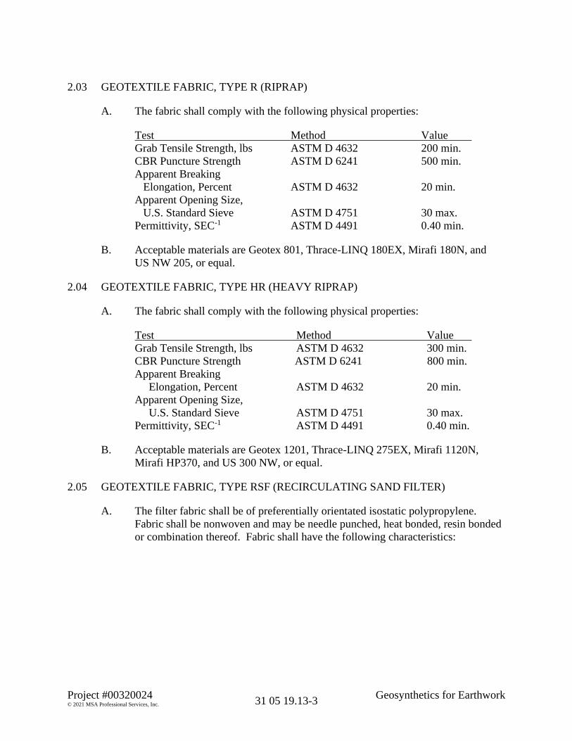
Project #00320024 Geosynthetics for Earthwork© 2021 MSA Professional Services, Inc. 31 05 19.13-3
2.03 GEOTEXTILE FABRIC, TYPE R (RIPRAP)
A. The fabric shall comply with the following physical properties:
Test Method ValueGrab Tensile Strength, lbs ASTM D 4632 200 min.CBR Puncture Strength ASTM D 6241 500 min.Apparent Breaking
Elongation, Percent ASTM D 4632 20 min.Apparent Opening Size,
U.S. Standard Sieve ASTM D 4751 30 max.Permittivity, SEC-1 ASTM D 4491 0.40 min.
B. Acceptable materials are Geotex 801, Thrace-LINQ 180EX, Mirafi 180N, andUS NW 205, or equal.
2.04 GEOTEXTILE FABRIC, TYPE HR (HEAVY RIPRAP)
A. The fabric shall comply with the following physical properties:
Test Method ValueGrab Tensile Strength, lbs ASTM D 4632 300 min.CBR Puncture Strength ASTM D 6241 800 min.Apparent Breaking
Elongation, Percent ASTM D 4632 20 min.Apparent Opening Size,
U.S. Standard Sieve ASTM D 4751 30 max.Permittivity, SEC-1 ASTM D 4491 0.40 min.
B. Acceptable materials are Geotex 1201, Thrace-LINQ 275EX, Mirafi 1120N,Mirafi HP370, and US 300 NW, or equal.
2.05 GEOTEXTILE FABRIC, TYPE RSF (RECIRCULATING SAND FILTER)
A. The filter fabric shall be of preferentially orientated isostatic polypropylene.Fabric shall be nonwoven and may be needle punched, heat bonded, resin bondedor combination thereof. Fabric shall have the following characteristics:

Project #00320024 Geosynthetics for Earthwork© 2021 MSA Professional Services, Inc. 31 05 19.13-4
ValueMinimum
Test Property Test Method Requirements1
Nominal Weight (oz/yd2) ASTM D5261 8.0Grab Tensile (lbs) ASTM D4632 205Grab Elongation At Break (%) ASTM D4632 50Puncture Resistance (lbs) ASTM D4833 95Trapezoidal Tear (lbs) ASTM D4533 85Mullen Burst (psi) ASTM D3786 300Water Flow Rate (gpm/ft2) ASTM D4491 130Permittivity (sec-1) ASTM D4491 1.6Permeability kv (cm/sec) ASTM D4491 0.4A.O.S.2 (sieve size) ASTM D4751 120-80UV Resistance (500 hrs)3 ASTM D4355 >85pH Resistance 2-13
B. Acceptable manufacturer of filter fabric materials are Phillips 66, Polyfelt, Mirafi,Du Pont, Webtec, or equal.
PART 3 EXECUTION
3.01 GENERAL
A. Installation procedures shall be in accordance with manufacturer’srecommendations and as specified herein.
B. Sewing. All factory and field seams shall be sewn with a thread having the sameor greater durability as the material in the fabric. A 401 stitch conforming toFederal Standard No. 751a shall be used for all seams. All seams shall develop atensile strength equal to or greater than 60 percent of the specified grab tensilestrength of the fabric, unless otherwise specified.
3.02 GEOTEXTILE FABRIC, TYPE SAS
A. Prior to the placement of the geotextile fabric, the subgrade shall be smoothed,shaped and compacted to the required grade, section, and density. After the fabrichas been placed on the subgrade area, no traffic or construction equipment will bepermitted to travel directly on the fabric.
B. Weight or pins may be required to prevent lifting of the fabric by wind.
1 Values in weaker principal direction. All minimum values represent minimum average roll values (i.e., testresults from any sampled roll in a lot, tested in accordance with ASTM D 4759 shall meet or exceed the minimumvalues listed).
2 Small sieve size number represents the maximum average roll value.3 UV resistance testing is based on results from independent conformance testing.
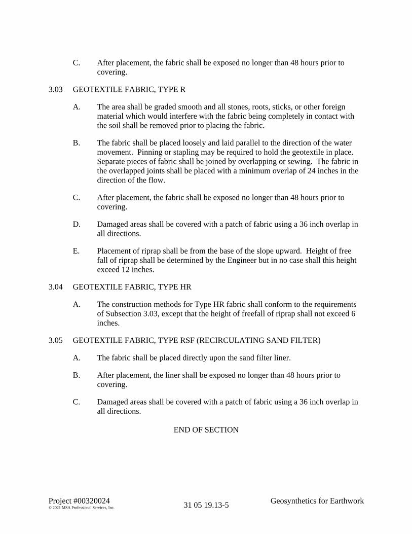
Project #00320024 Geosynthetics for Earthwork© 2021 MSA Professional Services, Inc. 31 05 19.13-5
C. After placement, the fabric shall be exposed no longer than 48 hours prior tocovering.
3.03 GEOTEXTILE FABRIC, TYPE R
A. The area shall be graded smooth and all stones, roots, sticks, or other foreignmaterial which would interfere with the fabric being completely in contact withthe soil shall be removed prior to placing the fabric.
B. The fabric shall be placed loosely and laid parallel to the direction of the watermovement. Pinning or stapling may be required to hold the geotextile in place.Separate pieces of fabric shall be joined by overlapping or sewing. The fabric inthe overlapped joints shall be placed with a minimum overlap of 24 inches in thedirection of the flow.
C. After placement, the fabric shall be exposed no longer than 48 hours prior tocovering.
D. Damaged areas shall be covered with a patch of fabric using a 36 inch overlap inall directions.
E. Placement of riprap shall be from the base of the slope upward. Height of freefall of riprap shall be determined by the Engineer but in no case shall this heightexceed 12 inches.
3.04 GEOTEXTILE FABRIC, TYPE HR
A. The construction methods for Type HR fabric shall conform to the requirementsof Subsection 3.03, except that the height of freefall of riprap shall not exceed 6inches.
3.05 GEOTEXTILE FABRIC, TYPE RSF (RECIRCULATING SAND FILTER)
A. The fabric shall be placed directly upon the sand filter liner.
B. After placement, the liner shall be exposed no longer than 48 hours prior tocovering.
C. Damaged areas shall be covered with a patch of fabric using a 36 inch overlap inall directions.
END OF SECTION

THIS PAGE INTENTIONALLY LEFT BLANK

31 11 00-1Project #0030024 Clearing and Grubbing© 2021 MSA Professional Services, Inc.
SECTION 31 11 0012
CLEARING AND GRUBBING3
PART 1 GENERAL4
1.01 APPLICABLE PROVISIONS5
A. Applicable provisions of Division 01 shall govern work of this section.6
1.02 APPLICABLE PUBLICATIONS7
A. The following publications of the issues listed below, but referred to thereafter by8basic designation only, form a part of this specification to the extent indicated by9the reference thereto.101. State of Wisconsin, Department of Transportation, Standard Specifications11
for Highway and Structure Construction, Current Edition at time of bid12opening.13
1.03 DESCRIPTION OF WORK14
A. Under this item the Contractor shall furnish all equipment and labor necessary to15cut and dispose of any vegetation within the clearing limits as described in this16section and specified herein.17
1.04 RELATED WORK ELSEWHERE18
A. Procurement and Contracting Requirements - Division 00 (All Sections)19
1.05 SUBMITTALS (NONE)20
1.06 OPERATION/MAINTENANCE MANUALS AND INSTRUCTIONS (NONE)21
PART 2 PRODUCTS AND MATERIALS (N/A)22
PART 3 CONSTRUCTION METHODS23
3.01 CLEARING AND GRUBBING24
A. Clearing and Grubbing shall consist of cutting and disposing of trees, brush,25windfalls, logs, and other vegetation occurring within the clearing limits, and the26removing and disposing of roots, stumps, stubs, grubs, logs and other timber from27within the grubbing limits.28
B. All work performed under this section shall be done in accordance with Subsection29201.3 of the State of Wisconsin, Department of Transportation, Standard30Specifications, with the following exceptions and additions:31

31 11 00-2Project #0030024 Clearing and Grubbing© 2021 MSA Professional Services, Inc.
1. Clearing and Grubbing Limits defined as follows:1a. Trees/brush as individually marked for removal.2b. Between lines 3 feet outside the grading limits (slope-intercept line)3
of the roadway cuts and fills, including intercepting embankments,4channels, ditches, borrow pits, and marsh or waste disposal area.5
c. Other parts of the right-of-way as designated in the plans or special6provisions.7
d. With Engineer’s approval, areas with vegetation that interferes with8excavation, embankment, or other construction operations.9
e. At no time shall Clearing and Grubbing operations extend beyond10the right-of-way without written approval from both Engineer and11Owner.12
f. At no time shall Clearing and Grubbing operations occur on trees,13brush, or other vegetation clearly marked for preservation.14
3.02 DISPOSAL OF MATERIALS15
A. Material removed shall be removed from the site and disposed of by the Contractor16in accordance with all local codes and ordinances.17
PART 4 MEASUREMENT AND PAYMENT18
4.01 GENERAL19
A. Clearing and Grubbing shall be paid for at the bid price in accordance with one of20the following methods, unless indicated otherwise in the Bid Schedule or Special21Procedures - Division 01.22
B. All work specified herein shall be considered in each of the measurement and23payment method(s) stipulated, unless indicated otherwise in the Bid Schedule or24Special Procedures - Division 01.25
C. The following incidental Clearing and Grubbing operations required to perform the26work will not be measured, and will be considered inclusive to the work for which27the incidental Clearing and Grubbing must occur:281. Clearing areas of light brush, shrubs, and other vegetation that Contractor29
removes with a brush scythe or mowing machine.302. Clearing areas containing logs, tree roots, roots of brush and shrubs, and31
other vegetation having a woody structure that the Contractor can remove32with a rooter.33
3. Trimming overhanging limbs and branches to provide required clearance.344. Clearing and Grubbing borrow pits.35

31 11 00-3Project #0030024 Clearing and Grubbing© 2021 MSA Professional Services, Inc.
4.02 CLEARING AND GRUBBING1
A. Clearing and Grubbing, Inch of Diameter. When so provided, measurement for2Clearing and Grubbing will be by the inch of diameter acceptably completed. The3diameter of the tree at a distance 4 feet above the existing ground level will be used4(diameter will be computed by dividing circumference by 3.14). Only those trees5and stumps larger than 3-inches in diameter will be added to the measurement.6Measurement will be rounded to the nearest inch. Payment will be made at the7contract unit price bid per inch of diameter cleared and grubbed.8
B. Clearing and Grubbing, Square Yards. When so provided, measurement for9Clearing and Grubbing will be by the square yard of horizontal area bounded by10the trunks cut and/or grubbed. Payment for Clearing and Grubbing shall be made11at the contract square yard price bid or as specified in Special Procedures -12Division 01.13
C. Clearing and Grubbing, Lump Sum. When so provided, payment for Clearing and14Grubbing shall be made at the contract lump sum price bid or as specified in Special15Procedures - Division 01.16
D. Clearing and Grubbing, Inclusive. When no quantity is provided, Clearing and17Grubbing shall be considered inclusive in the payment for contract work related to18the associated construction.19
20END OF SECTION21

THIS PAGE INTENTIONALLY LEFT BLANK

Project #00320024 Granular Fill© 2021 MSA Professional Services, Inc. 31 23 23.14-1
SECTION 31 23 23.1412
GRANULAR FILL3
PART 1 GENERAL4
1.01 APPLICABLE PROVISIONS5
A. Applicable provisions of Division 01 shall govern work of this section.6
1.02 APPLICABLE PUBLICATIONS7
A. The following publications of the issues listed below, but referred to thereafter by8basic designation only, form a part of this specification to the extent indicated by the9reference thereto.101. State of Wisconsin, Department of Transportation, Standard Specifications11
for Highway and Structure Construction, Current Edition at time of bid12opening.13
2. American Society for Testing and Materials (ASTM), Annual Book of14ASTM Standards, Current Edition.15
1.03 DESCRIPTION OF WORK16
A. The work covered under this section shall consist of furnishing all material,17equipment, and labor required to execute the filling, compaction, and testing of all18subgrade excavations for this project.19
1.04 RELATED WORK ELSEWHERE20
A. Procurement and Contracting Requirements - Division 00 (All Sections)21
B. Subgrade Preparation - Division 3122
1.05 SUBMITTALS (NONE)23
1.06 OPERATION/MAINTENANCE MANUALS AND INSTRUCTIONS (NONE)24
PART 2 PRODUCTS AND MATERIALS25
2.01 GRANULAR FILL26
A. All granular subbase and granular fill materials shall conform to Section 209 of the27State of Wisconsin, Department of Transportation, Standard Specifications.28

Project #00320024 Granular Fill© 2021 MSA Professional Services, Inc. 31 23 23.14-2
PART 3 CONSTRUCTION METHODS1
3.01 COMPACTION2
A. Granular fill materials shall be mechanically compacted in 6 inch to 8 inch lifts to393 percent maximum dry density per modified proctor (ASTM-D1557).4
PART 4 MEASUREMENT AND PAYMENT5
4.01 GENERAL6
A. Granular fill shall be paid for at the bid price in accordance with one of the following7methods, unless indicated otherwise in the Bid Schedule or Special Procedures -8Division 01.9
B. All work specified herein shall be considered in each of the measurement and10payment method(s) stipulated, unless indicated otherwise in the Bid Schedule or11Special Procedures - Division 01.12
4.02 GRANULAR FILL13
A. Granular Fill, Cubic Yards. The measurement for granular fill shall be by the cubic14yard truck volume or as specified in Special Procedures - Division 01. Payment shall15be made at the contract unit price bid per cubic yard of granular fill installed, as16measured or as specified in Special Procedures - Division 01.17
B. Granular Fill, Ton. The measurement for granular fill shall be by the ton or as18specified in Special Procedures - Division 01. Weight tickets from approved truck19scales shall be provided. Payment shall be made at the contract unit price bid per ton20of granular fill installed, as measured or as specified in Special Procedures -21Division 01.22
23END OF SECTION24

Project #0030024 Erosion and Sedimentation Controls© 2021 MSA Professional Services, Inc. 31 25 00-1
SECTION 31 25 0012
EROSION AND SEDIMENTATION CONTROLS3
PART 1 GENERAL4
1.01 APPLICABLE PROVISIONS5
A. Applicable provisions of Division 01 shall govern work of this section.6
1.02 APPLICABLE PUBLICATIONS7
A. The following publications of the issues listed below, but referred to thereafter by8basic designation only, form a part of this specification to the extent indicated by the9reference thereto.101. State of Wisconsin, Department of Natural Resources (WDNR),11
Conservation Practice Standards, Current Edition.122. State of Wisconsin, Department of Transportation, Standard Specifications13
for Highway and Structure Construction, Current Edition at time of bid14opening.15
1.03 DESCRIPTION OF WORK16
A. The work under this section shall cover providing the necessary materials, equipment17and labor to control erosion and sedimentation controls by the methods specified18herein. If no specific quantities are shown on the contract drawings, the Contractor19shall use whatever quantities are necessary to prevent sediment transport off the job20site, into permanent manmade storm water conveyances or management facilities or21to Waters of the State.22
B. The Contractor will be required to provide erosion control as per the current edition23of the applicable State of Wisconsin, Department of Natural Resources (WDNR),24Conservation Practice Standards. Copies of these standards can be obtained by25contacting the following:26
27State of Wisconsin Department of Natural Resources28Non-Point Source and Land Management Section29101 South Webster Street, P.O. Box 792130Madison, WI 53707-792131
32or by visiting the following website:33http://dnr.wi.gov/topic/stormwater/standards/const_standards.html34
35

Project #0030024 Erosion and Sedimentation Controls© 2021 MSA Professional Services, Inc. 31 25 00-2
C. The Engineer has prepared an erosion control plan for this project. The intent of this1plan is to identify erosion control provisions for the construction site that comply2with local, state, and federal regulations. The Contractor shall submit for approval3by the appropriate regulatory agency any changes to the Erosion Control Plan, prior4to beginning any construction on the project which may cause erosion in the portion5of the site where the change to the Erosion Control Plan is proposed.6
1.04 RELATED WORK ELSEWHERE7
A. Procurement and Contracting Requirements - Division 00 (All Sections)8
B. Clearing and Grubbing - Division 319
C. Grading - Division 3110
D. Subgrade Preparation - Division 3111
E. Structural Excavation for Structures - Division 3112
F. Trenching and Backfilling - Division 3113
G. Riprap - Division 3114
1.05 SUBMITTALS (NONE)15
1.06 OPERATION/MAINTENANCE MANUALS AND INSTRUCTIONS (NONE)16
PART 2 PRODUCTS AND MATERIALS17
2.01 TOPSOIL18
A. Topsoil shall be fertile, friable, natural loam surface soil, reasonably free of subsoil,19clay lumps, brush, weeds and free of roots, stumps, stones larger than 2 inches in any20dimension, and other matter harmful to plant growth. Topsoil to supplement21insufficient topsoil on the site shall originate from local sources, but not from bogs or22marshes.23
2.02 LIME24
A. Lime used for soil amendment shall be agricultural grade limestone ground25sufficiently fine so that 80 percent passes a No. 8 sieve. Lime shall contain2680 percent calcium carbonate equivalent. Moisture shall not exceed 10 percent.27

Project #0030024 Erosion and Sedimentation Controls© 2021 MSA Professional Services, Inc. 31 25 00-3
2.03 FERTILIZER1
A. Fertilizer used in conjunction with seeding shall be dry, free-flowing granular2fertilizer suitable for application by agricultural fertilizer spreaders or blower3equipment, or non-volatile liquid commercial fertilizer, having an analysis of420-10-10 (Nitrogen-Phosphoric Acid-Potash), or equal, unless use of phosphorus5based fertilizers are banned by the community where the work is to be completed. In6such communities, an analysis of 20-0-10, or equal, shall be used. Fertilizer having7other analysis shall be applied at a rate to achieve at least the individual following8amounts of nutrient per unit area:9
10Nutrient Application Rate Application Rate11
(Per Acre) (Per 1000 Sq. Ft.)1213
Nitrogen (N) 100 pounds 2.3 pounds14Phosphoric Acid (P2O5) 50 pounds 1.2 pounds15Potash (K2O) 50 pounds 1.2 pounds16
2.04 SEEDING FOR CONSTRUCTION SITE EROSION CONTROL17
A. Seeding for Construction Sites shall conform with Wisconsin DNR Conservation18Practice Standard 1059.19
B. Seed mixtures shall conform to one of the following:201. WisDOT, 2003. State of Wisconsin Standard Specifications For Highway21
and Structure Construction. Section 630, Seeding.222. United States Department of Agriculture – Natural Resource Conservation23
Service Field Office Technical Guide Section IV, Standard 342, Critical Area24Planting.25
3. UWEX Publication A3434 Lawn and Establishment & Renovation.26
C. All seed shall conform to the requirements of the Wisconsin Statutes and of the27Administrative Code Chapter ATCP 20.01 regarding noxious weed seed content and28labeling.29
D. Seed mixtures that contain potentially invasive species or species that may be30harmful to native plant communities shall be avoided.31
E. Seed shall not be used later than one year after the test date that appears on the label.32
F. Seed shall be tested for purity, germination and noxious weed seed content and shall33meet the minimum purity and germination requirements as prescribed in the current34edition of Rules for Testing Seed, published by the Association of Official Seed35Analysts.36

Project #0030024 Erosion and Sedimentation Controls© 2021 MSA Professional Services, Inc. 31 25 00-4
2.05 MULCH FOR CONSTRUCTION SITES1
A. Mulching for construction sites shall conform with Wisconsin DNR Conservation2Practice Standard 1058.3
B. Mulch shall consist of natural biodegradable material such as plant residue (including4but not limited to straw, hay, wood chips, bark and wood cellulose fiber), or other5equivalent materials of sufficient dimension (depth or thickness) and durability to6achieve the intended effect for the required time period.7
C. Mulch shall be environmentally harmless to wildlife and plants. Materials such as8gravel, plastic, fabric, sawdust, municipal solid waste, solid waste byproducts1,9shredded paper, and non-biodegradable products shall not be used.10
D. Mulch shall be free of diseased plant residue (i.e., oak wilt), noxious weed seeds,11harmful chemical residues, heavy metals, hydrocarbons and other known12environmental toxicants.13
E. Marsh hay shall not be used as mulch in lowland areas but may be used on upland14sites to prevent the spread of invasive, nonnative species (i.e., reed canary grass)15commonly found in marsh hay.16
F. Straw and hay mulch that will be crimped shall have a minimum fiber length of176 inches.18
G. Wood chips or wood bark shall only be used for sites that are not seeded.19
2.06 EROSION MAT20
A. Non-Channel Erosion Mat products shall conform with Wisconsin DNR21Conservation Practice Standard 1052.22
B. Channel Erosion Mat products shall conform with Wisconsin DNR Conservation23Practice Standard 1053.24
C. Erosion mat shall conform to the requirements of the State of Wisconsin, Department25of Transportation, Product Acceptability List (PAL) for Erosion Control26Revegetative Mat (ECRM) and Turf-Reinforcement Mat (TRM).27
D. For mats that utilize netting, the netting shall be bonded to the parent material to28prevent separation of the net for the life of the product.29
E. For urban class mats the following material requirements shall be adhered to:301. Only 100% organic biodegradable netted products are allowed, including31
parent material, stitching, and netting.322. The netting shall be stitched with biodegradable thread/yarn to prevent33
separation of the net from parent material.343. All materials and additive components used to manufacture the anchoring35
devices shall be completely biodegradable as determined by ASTM D 5338.36

Project #0030024 Erosion and Sedimentation Controls© 2021 MSA Professional Services, Inc. 31 25 00-5
4. Mats with photodegradable netting shall not be installed after September 1st.15. Steel wire pins or stables shall not be used in lawns.2
2.07 SEEDING AND SODDING3
A. Seeding and sodding shall conform to Seeding - Division 32 and Sodding -4Division 32.5
2.08 STRAW BALE EROSION BARRIERS6
A. Straw Bale (Sediment Bale Barriers) shall conform with Wisconsin DNR7Conservation Practice Standard 1055.8
B. Bales used for erosion control shall be either hay or straw, shall have rectangular9surfaces, and shall be tightly bound with twine, not wire. The material in the bales10shall be reasonably free of grain, weed seed and mold, and shall be dry and suitable11for the purpose intended.12
C. The minimum cross sectional area for wood stakes shall be 2.0 by 2.0 inches13nominal.14
D. The minimum diameter of steel (rebar) stakes shall be one-half inch.15
2.09 SEDIMENT CONTROL FENCE (SILT FENCE)16
A. Silt Fence shall conform with Wisconsin DNR Conservation Practice Standard 1056.17
B. Silt fence shall be in accordance with Section 628.2.6 of the State of Wisconsin,18Department of Transportation, Standard Specifications for Highway and Structure19Construction.20
C. Wood Posts:211. Wood Posts used to support the fabric shall be at least 2 inch x 2 inch in22
cross-section and shall be a minimum of 12 inches longer than the height of23the silt fence. Posts shall be made from kiln-dried hickory or Oak.24
2. Staples used to attach silt fence to wood posts shall be at least 0.5-inches in25length.26
D. Steel Supports:271. Steel posts shall be at least 5 feet long with a strength of 1.33 pounds per foot28
and shall have projections for the attachment of fasteners.292. The silt fence fabric shall be attached in at least three places on the upslope30
side with 50 pound plastic tie straps or wire fasteners.31
E. Silt fence shall have a support cord.32

Project #0030024 Erosion and Sedimentation Controls© 2021 MSA Professional Services, Inc. 31 25 00-6
F. The Contractor shall furnish upon request a manufacturer’s Certificate of1Compliance that the geotextile fabric as furnished meets the above requirements.2
G. Silt Fence shall be installed in accordance with Wisconsin DNR Conservation3Practice Standard 1056.4
2.10 STONE DITCH CHECKS5
A. Stone Ditch Checks shall be installed in accordance with Wisconsin DNR6Conservation Practice Standard 1062.7
2.11 RIPRAP8
A. Riprap shall be established in accordance with Riprap - Division 31 of this9specification.10
2.12 LAND APPLICATION OF POLYACRYLAMIDE11
A. Land Application of Polyacrylamide shall be performed in accordance with12Wisconsin DNR Conservation Practice Standard 1050.13
2.13 STONE TRACKING PAD14
A. Stone Tracking Pads shall be established in accordance with Wisconsin DNR15Conservation Practice Standard 1057.16
B. The aggregate for tracking pads shall be 3 to 6 inch clear or washed stone. All17material to be retained on a 3-inch sieve.18
2.14 VEGETATIVE BUFFERS19
A. Vegetative Buffers for Construction shall be established in accordance with20Wisconsin DNR Conservation Practice Standard 1054.21
B. Prior to land disturbance the perimeter of vegetative buffers shall be flagged or22fenced to prevent equipment from creating ruts, compacting the soil and to prevent23damage to existing vegetation.24
C. Trees should not be cut down to establish a vegetative buffer. Other erosion control25measures are preferred.26
2.15 TEMPORARY SEDIMENT TRAPS27
A. Temporary Sediment Traps shall conform with Wisconsin DNR Conservation28Practice Standard 1063.29

Project #0030024 Erosion and Sedimentation Controls© 2021 MSA Professional Services, Inc. 31 25 00-7
B. The stone outlet of a Sediment Trap shall consist of a stone section of embankment1located at the discharge point. Stone shall consist of angular well graded 3 to 6 inch2clear washed stone.3
C. If filter fabric is indicated for the up-slope side of the stone outlet, a monofilament4type fabric shall be used (such as WisDOT Type FF or equivalent).5
2.16 TEMPORARY CONSTRUCTION SITE DIVERSION6
A. Temporary Construction Site Diversions shall conform to Wisconsin DNR7Conservation Practice Standard 1066.8
2.17 DUST CONTROL9
A. Dust Control measures shall be implemented in accordance with Wisconsin DNR10Conservation Practice Standard 1068.11
B. Asphalt and petroleum based products shall not be used for dust control.12
C. Mulch or seed and mulch may be applied to protect exposed soil from wind erosion13according to the provisions of WDNR Conservation Practice Standard 105814Mulching for Construction Sites and 1059 Seeding for Construction Site Erosion15Control.16
D. Polymers may be used for dust control according to the provisions of WDNR17Conservation Practice Standard 1050 Erosion Control Land Application of Polymers.18
E. Tackifiers and Soil Stabilizers Type A – Products must be selected from the19WisDOT Erosion Control PAL.20
F. Solid board fences, snow fences, burlap fences, crate walls, bales of hay and similar21material may be used to control air currents and blown soil.22
2.18 CONSTRUCTION SITE DE-WATERING23
A. Construction Site Dewatering activities shall be conducted in accordance with24Wisconsin DNR Conservation Practice Standard 1061.25
2.19 STORM DRAIN INLET PROTECTION26
A. Storm Drain Inlet Protection shall conform Wisconsin DNR Conservation Practice27Standard 1060.28
B. All fabrics used as part of an inlet protection device must be selected from the list of29approved fabrics certified for inlet protection, Geotextile Fabric, Type FF in the30current edition of the WisDOT Product Acceptability List (PAL).31

Project #0030024 Erosion and Sedimentation Controls© 2021 MSA Professional Services, Inc. 31 25 00-8
C. Inlet Protection Barriers include, but are not limited to, straw bales, sandbags, other1material filled bags and socks, and stone weepers.2
D. Manufactured bags, when used, shall conform to the standards below:31. Minimum Size 14 x 26 inches42. Grab Tensile strength of fabric, ASTM D-4632 = 95 lb. min.53. UV stability, ASTM D-4355 = 70 % min.64. Fabric shall be sewn together with double stitching.7
E. Straw Bale installation shall conform to the criteria outlined in the WDNR8Conservation Practice Standard (1055) Sediment Bale Barrier (Non-Channel).9
F. Stone weeper installation shall conform to the criteria in WDNR Conservation10Practice Standard (1063) Sediment Trap.11
2.20 DITCH CHECK (CHANNEL)12
A. Ditch Checks for erosion and sediment control in drainage ditches and channels shall13conform Wisconsin DNR Conservation Practice Standard 1062.14
B. Stone ditch checks shall be constructed of a well-graded angular stone, a D50 of153 inch or greater, sometimes referred to as breaker run or shot rock.16
C. Manufactured products listed in WisDOT’s PAL are also acceptable for temporary17ditch checks.18
D. Silt fence and single rows of straw bales are not permitted.19
2.21 LAND APPLICATION OF ANIONIC POLYACRYLAMIDE (POLYMERS, PAM).20
A. Land Application of Anionic Polyacrylamide (PAM) shall conform Wisconsin DNR21Conservation Practice Standard 1050.22
B. Anionic PAM mixtures shall be environmentally benign, harmless to fish, aquatic23organisms, wildlife, and plants. Anionic PAM mixtures shall be non-combustible.24
C. Cationic PAM shall not be used at any level. Anionic PAM mixtures shall have25£0.05% free acrylamide monomer by weight as established by the Food and Drug26Administration (FDA) and the Environmental Protection Agency (EPA).27
D. The manufacturer or supplier shall provide a product expiration date for anionic28PAM mixtures based on product expiration date of PAM in pure form. PAM shall29not be used if the expiration date will be reached prior to establishment of vegetation30in areas where PAM is to be used.31
E. Contractor shall store and mix polymer in accordance with manufacturer or supplier32written instructions.33

Project #0030024 Erosion and Sedimentation Controls© 2021 MSA Professional Services, Inc. 31 25 00-9
PART 3 CONSTRUCTION METHODS1
3.01 EROSION CONTROL REQUIREMENTS2
A. The erosion control requirements specified in the project Storm Water Management3Plan shall be adhered to at all times.4
B. Temporary and permanent erosion control measures shall be performed by the5Contractor. The Contractor shall control water pollution, erosion, and siltation6through the use of intercepting embankments, berms, dikes, dams, settling basins,7slope paving, ditch checks, riprap, mulches, erosion mats, seeding, sodding, plantings8and other erosion control devices or methods.9
C. The Contractor shall submit for approval his plan of operations for accomplishing10temporary and permanent erosion control work relating to grubbing, grading, paving11and other work which might create erosion.12
D. The area of erosive land exposed to the elements by grubbing, excavation, borrow13and fill operations at any one time shall be minimized to the maximum extent14practicable and the duration of such exposure prior to final trimming, finishing and15seeding or application of temporary erosion control measures shall be as short as16practicable. Construction in and adjacent to rivers, streams, lakes, or other17waterways shall be performed in such a manner as to avoid washing, sloughing or18deposition of materials into such waterways which would obstruct or impair the flow19thereof thus endangering the roadway or stream banks, or which would result in20undue or avoidable contamination, pollution or siltation of such waterways.21
E. The Owner or Designated Representative shall have full authority to suspend or limit22grading and other operations pending adequate performance of such permanent23erosion control measures as finish grading, topsoiling, mulching, matting and seeding24and any temporary erosion control measures ordered by the Engineer.25
F. Grubbing and grading operations shall be performed in proper sequence with other26work to minimize erosion. Intercepting ditches or dikes shall be constructed as soon27as practical after clearing and grubbing operations are completed and prior to or28during the operations of excavating the cuts. Where erosion is likely to be a29problem, the permanent erosion control measures shall follow immediately after the30grading operations if conditions permit, unless the Engineer shall authorize31temporary erosion control measures.32

Project #0030024 Erosion and Sedimentation Controls© 2021 MSA Professional Services, Inc. 31 25 00-10
G. Water pumped from the site shall be treated by temporary sedimentations basins, grit1chambers, sand filters, upslope chambers, hydro-cyclones, swirl concentrators, or2other appropriate controls designed and used to remove total suspended solids (TSS)3to 40 mg/l or less for the highest dewatering pumping rate. If the water is4demonstrated to contain less than 40 mg/l TSS during dewatering operations, then no5control is needed before discharge. Water may not be discharged in a manner that6causes erosion of the site or receiving channels. Construction Site Dewatering7activities shall be conducted in accordance with Wisconsin DNR Conservation8Practice Standard 1061.9
H. The Contractor shall take all possible precautions to prevent sediment from being10tracked onto public or private roadways. Any sediment reaching a public or private11road shall be removed by street cleaning (not flushing) before the end of each12workday.13
I. All storm drain or culvert inlets shall be protected with appropriate erosion control14practices as identified in the appropriate Conservation Practice Standard.15Channelized runoff from adjacent areas passing through the site shall be diverted16around disturbed areas, if practical. Otherwise, the channel shall be protected. Sheet17flow runoff from adjacent areas greater than 10,000 square feet in area shall also be18diverted around disturbed areas unless shown to have resultant runoff velocities of19less than 0.5 ft/sec across the disturbed area for one-year design storms having a20duration of from 0.5 to 24 hours. Diverted runoff shall be conveyed in a manner that21will not erode the conveyance and receiving channels.22
J. All disturbed ground left inactive for seven (7) or more days shall be stabilized by23seeding or sodding (only prior to October 15) or by mulching or covering, or other24equivalent control measure.25
K. For sites with more than 10 acres disturbed at one time, or if a channel originates in26the disturbed area, one or more Temporary Sediment Traps shall be constructed in27accordance with Wisconsin DNR Conservation Practice Standard 1063. The basin28discharge rate shall also be sufficiently low as to not cause erosion along the29discharge channel or the receiving water.30
L. For sites with less than 10 acres disturbed at one time, sediment control fences, hay31bales, or equivalent control measures shall be placed along all sideslope and32downslope sides of the site. If a channel or area of concentrated runoff passes33through the site, sediment control fences shall be placed along the channel edges to34reduce sediment reaching the channel.35
M. Any soil or dirt storage piles containing more than ten cubic yards of material should36not be located with a downslope drainage length of less than 25 feet to a roadway or37drainage channel. If remaining for more than seven (7) days, they shall be stabilized38by mulching, vegetative cover, tarps, or other means. Erosion from piles which will39be in existence for less than seven (7) days shall be controlled by placing hay bales or40

Project #0030024 Erosion and Sedimentation Controls© 2021 MSA Professional Services, Inc. 31 25 00-11
sediment control fence barriers around the pile. In-street utility repair or construction1soil; or dirt storage piles located closer than 25 feet to a roadway or drainage channel2must be covered with tarps or a suitable alternative control must be used if exposed3for more than seven (7) days, and storm drain or culvert inlets must be protected with4straw bales or other appropriate filtering barriers (CPS 1060).5
3.02 TEMPORARY SEEDING6
A. Seeding for Construction Sites shall be installed and maintained in accordance with7Wisconsin DNR Conservation Practice Standard 1059.8
B. Temporary Seeding (Cover Crop) - Areas needing protection during periods when9permanent seeding is not applied shall be seeded with annual species for temporary10protection. See table below for seeding rates of commonly used species. The residue11from this crop may either be incorporated into the soil during seedbed preparation at12the next permanent seeding period or left on the soil surface and the planting made as13a no-till seeding.14
15Species Lbs/Acre Percent Purity16Oats 1311 9817Cereal Rye 1312 9718Winter wheat 1312 9519Annual Ryegrass 802 9720
211 Spring and summer seeding222 Fall seeding23
C. Permanent Seeding - Rates shall be based on pounds or ounces of Pure Live Seed24(PLS) per acre. If a nurse crop is used in conjunction with permanent seeding, the25nurse crop shall not hinder establishment of the permanent vegetation. A nurse crop26shall be applied at 50% its temporary seeding rate when applied with permanent27seed.28
D. Inoculation - Legume seed shall be inoculated in accordance with the manufacturer’s29recommendations. Inoculants shall not be mixed with liquid fertilizer.30
E. Sowing311. Seed grasses and legumes no more than 1/4 inch deep. Distribute seed32
uniformly. Mixtures with low seeding rates require special care in sowing to33achieve proper seed distribution.34
2. Seed may be broadcast, drilled, or hydroseeded as appropriate for the site.353. Seed when soil temperatures remain consistently above 53°F. Dormant seed36
when the soil temperature is consistently below 53°F (typically37November 1st until snow cover). Seed shall not be applied on top of snow.38
F. Turf seedlings must not be mowed until the stand is at least 6 inches tall. Do not39mow closer than 3 inches during the first year of establishment.40

Project #0030024 Erosion and Sedimentation Controls© 2021 MSA Professional Services, Inc. 31 25 00-12
G. Alternate plans must be submitted for approval.1
3.03 APPLICATION OF STRAW OR HAY MULCH2
A. Mulching for Construction Sites shall be installed and maintained in accordance with3Wisconsin DNR Conservation Practice Standard 1058.4
B. Application Rate:51. Mulch shall cover a minimum of 80% of the soil surface for unseeded areas.6
For seeded areas, mulch shall be placed loose and open enough to allow some7sunlight to penetrate and air to circulate but still cover a minimum of 70% of8the soil surface.9
2. Mulch shall be applied at a uniform rate of 1½ to 2 tons per acre for sites that10are seeded, and 2 to 3 tons per acre for sites that are not seeded. This11application results in a layer of ½ to 1½ inches thick for seeded sites, and 1½12to 3 inches thick for sites not seeded.13
3. Wood chips or wood bark shall be applied at a rate of 6 to 9 tons per acre to14achieve a minimum of 80% ground cover. This application should result in a15layer of wood chips or wood bark ½ to 1½ inches thick.16
C. In areas where mulch is to be placed over seed, mulch shall be placed within 2417hours of seeding.18
D. Mulch Anchoring Methods - Anchoring of mulch shall be based on the type of mulch19applied, site conditions, and accomplished by one of the following techniques:201. Crimping: Immediately after spreading, the mulch shall be anchored by a21
mulch crimper or equivalent device consisting of a series of dull flat discs22with notched edges spaced approximately 8 inches apart. The mulch shall be23impressed in the soil to a depth of 1 to 3 inches.24
2. Polypropylene Plastic, or Biodegradable Netting: Apply plastic netting over25mulch application and staple according to manufacturer’s recommendations.26
3. Tackifier: Tackifier shall be sprayed in conjunction with mulch or27immediately after the mulch has been placed. Tackifiers must be selected28from those that meet the WisDOT Erosion Control Product Acceptability List29(PAL). Asphalt based products shall not be applied.30a. The tackifiers shall be applied at the following minimum application31
rates per acre:321) Latex-Base: mix 15 gallons of adhesive (or the33
manufacturer’s recommended rate which ever is greater) and34a minimum of 250 pounds of recycled newsprint (pulp) as a35tracer with 375 gallons of water.36
2) Guar Gum: mix 50 pounds of dry adhesive (or the37manufacturer’s recommended rate which ever is greater) and38a minimum of 250 pounds of recycled newsprint (pulp) as39tracer with 1,300 gallons of water.40

Project #0030024 Erosion and Sedimentation Controls© 2021 MSA Professional Services, Inc. 31 25 00-13
3) Other Tackifiers: (Hydrophilic Polymers) mix 100 pounds of1dry adhesive (or the manufacturer’s recommended rate which2ever is greater) and a minimum of 250 pounds of recycled3newsprint (pulp) as a tracer with 1,300 gallons of water.4
3.04 PLACING EROSION MAT5
A. Installation instructions shall be supplied by the manufacturer. The Contractor shall6install the mat in accordance with the manufacturer’s recommendations and in7accordance with Section 628.2 of the State of Wisconsin, Department of8Transportation, Standard Specifications for Highway and Structure Construction, and9the State of Wisconsin, Department of Transportation general requirements for10erosion mat except as may be modified herein.11
B. Erosion control revegetative mats shall be installed after all topsoiling, fertilizing,12liming and seeding is complete.13
C. The mat shall be in firm and intimate contact with the soil. It shall be installed and14anchored per the manufacturer’s recommendation.15
D. The mat shall be unrolled and draped loosely, without stretching, so that continuous16ground contact is maintained. In ditches, mat shall be unrolled and applied parallel17to the direction of drainage. On slopes, mat shall be applied parallel to the slope18direction.19
E. Turf-reinforcement mat shall be installed in conjunction with the topsoiling operation20and shall be followed by Erosion Control Revegetative Mat installation.21
F. At time of installation, document the manufacturer and mat type by retention of22material labels and manufacturer’s installation instructions. Retain this23documentation until the site has been stabilized.24
G. In channels and on slopes, each upslope and each downslope end of each piece of25mat shall be placed in a 4-inch trench, stapled on 12-inch centers, backfilled and26tamped. Where one roll ends and second roll starts, the upslope piece shall be27brought over the end of the downslope roll so that there is a 12 inch overlap, placed28in a 4 inch trench, stapled on 12 inch centers, backfilled and tamped. In channels,29erosion mats shall extend for whichever is greater: upslope one-foot minimum30vertically from the ditch bottom or 6 inches higher than the design flow depth.31
H. On slopes, where two or more widths of mat are applied, the two edges shall be32overlapped according to the manufacturer’s installation instructions and stapled at 1833to 24 inch intervals along the exposed edge of the lap joint. The body of the mat34shall be stapled in a grid pattern with staples 3 feet on center each way.35
I. Where heavy concentrations of water or extremely erodible soil conditions exist, as36noted on the contract drawings, erosion checks shall be installed at intervals of37

Project #0030024 Erosion and Sedimentation Controls© 2021 MSA Professional Services, Inc. 31 25 00-14
50 feet, or less. Such a check shall consist of a 4-inch deep trench perpendicular to1the flow direction across the entire width of the fabric. The mat shall be stapled at29-inch intervals along the bottom of the trench across the entire width of the mat.3The trench shall then be backfilled and tamped.4
J. If anchoring devices become loosened, or if any fabric loosens, is torn or5undermined, repairs shall be made immediately without additional compensation.6
K. Erosion mat when used in conjunction with fertilizing and seeding done for surface7restoration, shall be installed immediately after fertilizing and seeding operations8have been completed. Straw or hay mulch shall not be used under the fabric.9
L. Erosion mat shall at a minimum be inspected weekly and within 24 hours after every10precipitation event that produces 0.5 inches of rain or more during a 24-hour period.111. If there are signs of rilling under the mat, install more staples or more12
frequent anchoring trenches. If rilling becomes severe enough to prevent13establishment of vegetation, remove the section of mat where the damage has14occurred. Fill the eroded area with topsoil, compact, reseed and replace the15section of mat, trenching and overlapping ends per manufacturer’s16recommendations. Additional staking shall be provided where rilling was17filled.18
2. If the reinforcing plastic netting has separated from the mat, remove the19plastic and if necessary replace the mat.20
3. Maintenance shall be completed as soon as possible with consideration to site21conditions.22
3.05 VEGETATIVE BUFFERS23
A. Vegetative Buffers for Construction shall be installed and maintained in accordance24with Wisconsin DNR Conservation Practice Standard 1054.25
B. Trees should not be cut down to establish a vegetative buffer.26
C. A stand of dense vegetation shall be maintained to a height of 3 – 12 inches.27
D. Vegetative buffers shall at a minimum be inspected weekly and within 24 hours after28every precipitation event that produces 0.5 inches of rain or more during a 24-hour29period. Vegetative buffers shall be inspected for proper distribution of flows,30sediment accumulation and signs of rill formation.31
E. If the vegetative buffer becomes silt covered, contains rills, or is otherwise rendered32ineffective, other perimeter sediment control measures shall be installed. Eroded33areas shall be repaired and stabilized. Repair shall be completed as soon as possible34with consideration to site conditions.35

Project #0030024 Erosion and Sedimentation Controls© 2021 MSA Professional Services, Inc. 31 25 00-15
3.06 TEMPORARY SOD PLACEMENT1
A. The Contractor shall place sod with edges in close contact and with joints staggered.2Sod placement on slopes shall commence at the bottom of the slope, and the rows3shall be laid perpendicular to the slope. The edge of the sod at the tops of slopes4shall be turned slightly under, and a layer of soil shall be compacted over the edge to5direct surface drainage over the edge onto the top of the sod. Sod placement in areas6other than on slopes shall be made so that the top sod surface is flush with adjoining7surfaces.8
B. On slopes steeper than 4:1 horizontal to vertical, the Contractor shall stake the sod9with split cedar shingles, or other equally effective stakes, spaced from 18 to1036 inches apart along the longitudinal axis of the sod strip. These stakes shall be11placed near the top edge of the sod strip and shall be driven flush with the sod.12
C. After the sod is placed, it shall be rolled or firmly tamped to press the sod onto the13underlying soil. The Contractor shall, at the end of the day in which the sod is laid,14thoroughly soak all sodded areas by sprinkling them with water.15
D. Sod shall be maintained in a moist, growing condition. The Contractor shall repair16all areas damaged by erosion or traffic of any kind.17
3.07 PLACING HAY BALE BARRIERS18
A. Straw Bale (Sediment Bale Barriers) shall be installed and maintained in accordance19with Wisconsin DNR Conservation Practice Standard 1055.20
B. Sufficient bales shall be on the site to create the necessary barriers prior to the start of21groundbreaking operations. The bales shall be stacked and covered with plastic22sheeting until required for use.23
C. At a minimum, sediment bale barriers shall be placed in a single row, lengthwise on24the contour, with the ends of adjacent sediment bale barriers tightly abutting one25another. The holes between bales shall be chinked (filled by wedging) with straw,26hay or equivalent material to prevent water from escaping between the bales.27
D. The maximum allowable slope lengths contributing runoff to a sediment bale barrier28are specified below:29
30Slope Barrier Row Spacing31< 2% 100 feet322 to 5% 75 feet335 to 10% 50 feet3410 to 33% 25 feet3533 to 50% 20 feet36> 50% Not Permitted37

Project #0030024 Erosion and Sedimentation Controls© 2021 MSA Professional Services, Inc. 31 25 00-16
E. Sediment bale barriers shall not be placed perpendicular to the contour.1
F. The end of the sediment bale barrier shall be extended upslope to prevent water from2flowing around the barrier ends.3
G. Installed sediment bale barrier shall be a minimum of 10 inches high and shall not4exceed a maximum height of 20 inches from ground level.5
H. The barrier shall be entrenched and backfilled. A trench shall be excavated the width6of a sediment bale barrier and the length of the proposed barrier to a minimum depth7of 4 inches. After bales are staked and chinked, the excavated soil shall be backfilled8and compacted against the barrier. Backfill to ground level on the down slope side.9On the upslope side of the sediment bale barrier backfill to 4 inches above ground10level.11
I. At least two wood stakes, “T” or “U” steel posts, or 1/2 inch rebar driven through at12equidistance along the centerline of the barrier shall securely anchor each bale. The13first stake in each bale shall be driven toward the previously laid bale to force the14bales together. Stakes shall be driven a minimum 12-inches into the ground to15securely anchor the sediment bale barriers.16
J. Bales shall be installed so that bindings are oriented around the sides rather than17along the tops and bottoms of the bales in order to prevent deterioration of the18bindings.19
K. Sediment bale barriers shall, at a minimum, be inspected weekly and within 24 hours20after every precipitation event that produces 0.5 inches of rain or more during a 24-21hour period.22
L. Damaged or decomposed sediment bale barriers, any undercutting, or flow channels23around the end of the sediment bale barriers shall be repaired.24
M. Sediment shall be properly disposed of once the deposits reach 1/2 the height of the25sediment bale barrier.26
N. Sediment bale barriers and anchoring devices shall be removed and properly27disposed of when they have served their usefulness, but not before the upslope areas28have been permanently stabilized.29
O. Any sediment deposits remaining in place after the sediment bale barrier is no longer30required shall be dressed to conform to the existing grade, prepared, and seeded.31
3.08 CONSTRUCTION OF SEDIMENT CONTROL FENCE (SILT FENCE)32
A. Silt Fence shall be installed and maintained in accordance with Wisconsin DNR33Conservation Practice Standard 1056.34
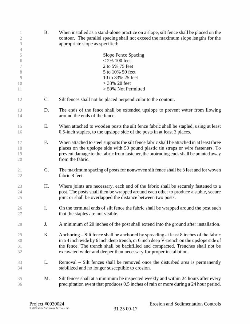
Project #0030024 Erosion and Sedimentation Controls© 2021 MSA Professional Services, Inc. 31 25 00-17
B. When installed as a stand-alone practice on a slope, silt fence shall be placed on the1contour. The parallel spacing shall not exceed the maximum slope lengths for the2appropriate slope as specified:3
4Slope Fence Spacing5< 2% 100 feet62 to 5% 75 feet75 to 10% 50 feet810 to 33% 25 feet9> 33% 20 feet10> 50% Not Permitted11
C. Silt fences shall not be placed perpendicular to the contour.12
D. The ends of the fence shall be extended upslope to prevent water from flowing13around the ends of the fence.14
E. When attached to wooden posts the silt fence fabric shall be stapled, using at least150.5-inch staples, to the upslope side of the posts in at least 3 places.16
F. When attached to steel supports the silt fence fabric shall be attached in at least three17places on the upslope side with 50 pound plastic tie straps or wire fasteners. To18prevent damage to the fabric from fastener, the protruding ends shall be pointed away19from the fabric.20
G. The maximum spacing of posts for nonwoven silt fence shall be 3 feet and for woven21fabric 8 feet.22
H. Where joints are necessary, each end of the fabric shall be securely fastened to a23post. The posts shall then be wrapped around each other to produce a stable, secure24joint or shall be overlapped the distance between two posts.25
I. On the terminal ends of silt fence the fabric shall be wrapped around the post such26that the staples are not visible.27
J. A minimum of 20 inches of the post shall extend into the ground after installation.28
K. Anchoring – Silt fence shall be anchored by spreading at least 8 inches of the fabric29in a 4 inch wide by 6 inch deep trench, or 6 inch deep V-trench on the upslope side of30the fence. The trench shall be backfilled and compacted. Trenches shall not be31excavated wider and deeper than necessary for proper installation.32
L. Removal – Silt fences shall be removed once the disturbed area is permanently33stabilized and no longer susceptible to erosion.34
M. Silt fences shall at a minimum be inspected weekly and within 24 hours after every35precipitation event that produces 0.5 inches of rain or more during a 24 hour period.36

Project #0030024 Erosion and Sedimentation Controls© 2021 MSA Professional Services, Inc. 31 25 00-18
N. Damaged or decomposed fences, undercutting, or flow channels around the end of1barriers shall be repaired or corrected.2
O. Sediment shall be properly disposed of once the deposits reach 1/2 the height of the3fence.4
3.09 STONE TRACKING PAD5
A. Stone Tracking Pads shall be installed and maintained in accordance with Wisconsin6DNR Conservation Practice Standard 1057.7
B. The tracking pad shall be installed prior to any traffic leaving the site.8
C. The aggregate shall be placed in a layer at least 12 inches thick. On sites with a high9water table, or where saturated conditions are expected during the life of the practice,10stone tracking pads shall be underlain with a WisDOT Type R geotextile fabric to11prevent migration of underlying soil into the stone.12
D. Tracking pads and tire washing stations shall, at a minimum, be inspected weekly13and within 24 hours after every precipitation event that produces 0.5 inches of rain or14more during a 24-hour period.15
E. The tracking pad performance shall be maintained by scraping or top-dressing with16additional aggregate.17
F. A minimum 12-inch thick pad shall be maintained.18
3.10 STORM DRAIN INLET PROTECTION19
A. Storm Drain Inlet Protection shall be installed and maintained in accordance with20Wisconsin DNR Conservation Practice Standard 1060.21
B. The contributing drainage area to the inlet protection device shall be one acre or less.22In instances were a larger contributing drainage area exists, runoff shall be routed23through a properly designed sediment trapping or settling device upstream of inlet.24
C. Other than Type D inlet protection devices, no gaps shall be left in the material used25that would allow the flow of water to bypass the inlet protection device.26
D. Filter Fabric Barrier Criteria - See Inlet Protection Detail271. Inlet protection Type A devices shall be utilized around inlets and unpaved28
areas until permanent stabilization methods have been established. Type A29devices shall be utilized on inlets prior to installation of curb and gutter or30pavement, and where safety considerations are not compromised on the site.31
2. Type B shall be utilized after the casting and grate are in place.323. Type D shall be utilized in areas where other types of inlet protection are33
identified as incompatible with roadway and traffic conditions, causing34

Project #0030024 Erosion and Sedimentation Controls© 2021 MSA Professional Services, Inc. 31 25 00-19
possible safety hazards when ponding occurs at the inlet. Type D shall only1be used after castings are in place on top of the inlet boxes.2
4. Type D inlet protection shall conform to the standard drawing as shown in3the contract drawings. There shall be a three-inch space between the bag and4the sides of the inlet to prevent the inlet sides from blocking the overflow;5and shall only be used in inlets deeper than 30 inches from the top of grate to6bottom of the inlet. If such clearance is not available, cinch or tie the sides of7the bag (with rope or ties) to provide clearance.8
E. Criteria Applicable to the Post-Paving/Curbing Phase of Construction91. Inlet protection Types B, C, and D are applicable to post paving construction.10
See Inlet Protection Detail.11a. Type B shall be utilized on inlets without curb box.12b. Type C shall be utilized on street inlets with curb heads. A 1½ inch x13
3½ inch (37 mm by 87 mm) minimum, piece of wood shall be14wrapped and secured in the fabric and placed in front of the curb head15as shown in the contract drawings. The wood shall not block the16entire opening of the curb box and be secured to the grate with wire17or plastic ties.18
c. Type D.19
F. Remove inlet protection devices once the contributing drainage area is stabilized20with appropriate vegetation or impervious area.21
G. Inlet protection shall be at a minimum inspected weekly and within 24 hours after22every precipitation event that produces 0.5 inches of rain or more during a 24-hour23period.24
H. Sediment deposits shall be removed and the inlet protection device restored to its25original dimensions when the sediment has accumulated between 1/3 to 1/2 the26design depth of the device, or when the device is no longer functioning as designed.27Removed sediment shall be deposited in a suitable area and stabilized.28
I. Any material falling into the inlet shall be removed.29
3.11 DITCH CHECK (CHANNEL)30
A. Ditch Checks for erosion and sediment control in drainage ditches and channels shall31be installed and maintained in accordance with Wisconsin DNR Conservation32Practice Standard 1062.33
B. Ditch checks shall be utilized during rough grading and shall be removed once the34final grading and channel stabilization is applied, unless intended to be part of a35permanent storm water management plan.36
C. Channel erosion mat or other nonerodible materials shall be placed at the base of a37ditch check, and extended a minimum of 6 feet, to prevent scour and washing out the38

Project #0030024 Erosion and Sedimentation Controls© 2021 MSA Professional Services, Inc. 31 25 00-20
toe of the ditch check. DNR Conservation Practice Channel Erosion Mat (1053)1contains criteria for the placement of erosion mat in this location.2
D. Stone ditch checks may be underlain by a nonwoven geotextile fabric to ease3installation and removal. If the geotextile fabric is extended, it can serve purpose4specified in item 3.11 C above.5
E. Chink or seal stone and rock ditch checks to minimize the flow through the ditch6check.7
F. For added stability, the base of a stone or rock ditch check shall be keyed into the soil8to a depth of 6-inches.9
G. Ditch checks shall, at a minimum, be inspected weekly and within 24 hours after10every precipitation event that produces 0.5 inches of rain or more during a 24 hour11period.12
H. Unless incorporated into a permanent storm water management system, ditch checks13shall be removed once the final grading and channel stabilization is applied.14
I. Maintenance shall be completed as soon as possible with consideration to site15conditions.16
3.12 TEMPORARY SEDIMENT TRAPS17
A. Temporary Sediment Traps shall be installed and maintained in accordance with18Wisconsin DNR Conservation Practice Standard 1063.19
B. Sediment traps shall be constructed prior to disturbance of up-slope areas and placed20so they function during all phases of construction.21
C. The depth of the sediment trap measured from the sediment trap bottom to the invert22of the stone outlet, shall be at least three feet to minimize re-suspension and provide23storage for sediment.24
D. The sediment trap shall have a length to width ratio of at least 2:1. The position of25the outlet to the inlet shall be as such to minimize short-circuiting of the water flow26path.27
E. Side slopes shall be no steeper than 2:1.28
F. Embankments of temporary sediment traps shall not exceed five feet in height29measured from the downstream toe of the embankment to the top of the30embankment. Construct embankments with a minimum top width of four feet, and31side slopes of 2:1 or flatter. Earthen embankments shall be compacted.32

Project #0030024 Erosion and Sedimentation Controls© 2021 MSA Professional Services, Inc. 31 25 00-21
G. Sediment traps shall be constructed with both a principal and emergency spillway.1The stone outlet of a sediment trap shall consist of a stone section of embankment2(stone outlet) located at the discharge point. The stone outlet section provides a3means of dewatering the basin back to the top of the permanent storage between4storm events, and also serves as a non-erosive emergency spillway for larger flow5events.6
H. The stone outlet shall have a minimum top width of 2 feet and a maximum side-slope7of 2:1.8
I. The stone outlet shall be protected from undercutting by excavating a keyway trench9across the stone foundation and up the sides to the height of the outlet.10
J. Sediment Traps shall, at a minimum, be inspected weekly and within 24 hours after11every precipitation event that produces 0.5 inches of rain or more during a 24-hour12period. Sediment may need to be removed more frequently.13
K. Deposits of sediment shall be removed when they reach a depth of one foot.14
L. If the outlet becomes clogged it shall be cleaned to restore flow capacity.15
M. Maintenance shall be completed as soon as possible with consideration given to site16conditions.17
N. Sediment traps shall be removed and the location stabilized after the disturbed area18draining to the sediment trap is stabilized and no longer susceptible to erosion.19
3.13 TEMPORARY CONSTRUCTION SITE DIVERSION20
A. Temporary Construction Site Diversions shall be installed and maintained in21accordance with Wisconsin DNR Conservation Practice Standard 1066.22
B. The minimum berm cross section shall have side slopes of 2:1 (horizontal:vertical) or23flatter, a minimum top width of two feet and a minimum height of 1.5 feet.24
C. Diversions that are to serve longer than 30 days shall be stabilized as soon as they are25constructed.26
D. Diversions shall, at a minimum, be inspected weekly and within 24 hours after every27precipitation event that produces 0.5 inches of rain or more during a 24-hour period.28
E. Maintenance shall be completed as soon as possible with consideration to site29conditions.30
F. Accumulated sediment shall be removed when it reaches one half the height of the31diversion berm.32

Project #0030024 Erosion and Sedimentation Controls© 2021 MSA Professional Services, Inc. 31 25 00-22
G. Diversions shall be removed and the area stabilized according to construction1contract drawings.2
3.14 DUST CONTROL3
A. Dust Control measures shall be installed and maintained in accordance with4Wisconsin DNR Conservation Practice Standard 1068.5
B. Polymers may be used in areas that do not receive vehicle traffic. Dry applied6polymers must be initially watered for activation to be effective for dust control.7Polymers shall be utilized in accordance with the provisions of WDNR Conservation8Practice Standard 1050 Erosion Control Land Application of Polymers.9
C. Tackifiers and Soil Stabilizers Type A – Products must be installed at rates10conforming to the WisDOT Erosion Control PAL.11
D. Chlorides shall be applied according to the most recent version of the WisDOT12Standard Specifications for Highway and Bridge Construction.13
E. Barriers - Barriers shall be placed at right angles to prevailing wind currents at14intervals of about 15 times the barrier height.15
F. Areas that have dust control practices shall at a minimum be inspected daily.16
3.15 LAND APPLICATION OF ANIONIC POLYACRYLAMIDE (POLYMERS).17
A. Land Application of Anionic Polyacrylamide (polymers) shall be installed and18maintained in accordance with Wisconsin DNR Conservation Practice Standard191050.20
B. Application rates shall not exceed manufacturer’s written application rate21recommendations that shall not exceed the WDNR use restrictions.22
C. Maximum application rates, in parts per million (ppm or mg/L or mg/kg), shall be23determined by multiplying 1.4 by the number of pounds applied per acre. This24number shall be less than or equal to the WDNR use restriction. Repeated25applications of anionic PAM mixtures may be applied, if necessary, to ensure26adequate effectiveness.27
D. The application method shall provide uniform coverage to the target area and avoid28drift to non-target areas.29
E. When used on bare soil, without seed or mulch, anionic PAM mixtures shall be used30on slopes 2.5:1 or flatter.31
F. Anionic PAM mixtures shall not be applied to channel bottoms.32
Project #0030024 Erosion and Sedimentation Controls© 2021 MSA Professional Services, Inc. 31 25 00-23
G. The applicator of anionic PAM mixture shall document, at the time of application,1the following: name of applicator, application rate per acre, date applied, product2type, weather conditions during application, and method of application. Copies of3this documentation shall be entered into the contractor’s monitoring log or project4diary and made available upon request.5
H. Unused liquid anionic PAM mixtures shall be minimized. Excess material shall not6be applied at a rate greater than the maximum application rate. Disposal shall not7occur in storm water conveyance systems (i.e., storm sewer manholes, storm sewer8inlets, ditches, and culverts).9
I. PAM shall not be used within 30 feet of surface waters of the state.10
J. Maintenance will consist of reapplying anionic PAM mixtures to disturbed areas,11including high use traffic areas, which interfere in the performance of this practice.12
K. AnionicPAM mixtures should be reapplied in areas where wind or rill erosion is13apparent and whenever an area has been graded, driven upon, or otherwise disturbed14since the anionic PAM mixture was last applied.15
PART 4 MEASUREMENT AND PAYMENT16
4.01 GENERAL17
A. Erosion and sedimentation controls shall be paid for at the bid price in accordance18with one of the following methods, unless indicated otherwise in the Bid Schedule or19Special Procedures - Division 01.20
B. All work specified herein shall be considered in each of the measurement and21payment method(s) stipulated, unless indicated otherwise in the Bid Schedule or22Special Procedures - Division 01.23
4.02 EROSION AND SEDIMENTATION CONTROLS24
A. Erosion and Sedimentation Controls, Lump Sum. When so provided, payment for25erosion and sedimentation controls shall be made at the contract lump sum price bid.26
B. Erosion and Sedimentation Controls, Inclusive. When no quantity is provided,27erosion and sedimentation controls shall be considered inclusive to payment for28contract work related to the associated construction.29
30
END OF SECTION31

THIS PAGE INTENTIONALLY LEFT BLANK

Project #00320024 Riprap© 2021 MSA Professional Services, Inc. 31 37 00-1
SECTION 31 37 00
RIPRAP
PART 1 GENERAL
1.01 SECTION INCLUDES
This section covers stone material suppliers, production and quality control as theyrelate to construction of all armorstone structures in the project.
1.02 APPLICABLE PUBLICATIONS
A. The following publications of the issues listed below, but referred to thereafter bybasic designation only, form a part of this specification to the extent indicated bythe reference thereto.1. State of Wisconsin, Department of Transportation, Standard
Specifications for Highway and Structure Construction, Current Edition attime of bid opening.
2. US Army Corps of Engineers Shoreline Protection Manual, CurrentEdition at time of bid opening.
1.03 RELATED WORK ELSEWHERE
A. Procurement and Contracting Requirements - Division 00 (All Sections)B. 31 05 19.16 Geosynthetics for Earthwork
1.04 QUALITY CONTROL
A. General
1. The Contractor is responsible for, and shall establish and maintain, qualitycontrol for all stone production performed in the quarry and hauling underhis contract to ensure compliance with the specifications.
2. The Contractor shall exercise care in hauling and unloading of stone duringall phases of construction to prevent cracking, splitting, spalling, etc., thatwould otherwise lead to rejection at the job site.
B. Production Quality Control and Quarry Inspection
1. The Contractor shall provide a Quality Control Program (QCP) and anappropriate full-time quarry and loading facility inspector(s), who shall verifythat all stone produced and delivered to the job site conforms to therequirements of this section. The QCP and inspector activities shallinclude, but not be limited to:
Project #00320024 Riprap© 2021 MSA Professional Services, Inc. 31 37 00-2
a. Maintaining a daily log, compiled in table form, presented in a clearand legible fashion indicating the following as a minimum:
· quantity of stone produced to date for each stone type;· quantity shipped to date for each stone type;· running average stone weight for all material produced for the
project.
Running average stone weight shall be determined by dividing thetotal weight of stone on each truck by the number of stones on thetruck.
b. Loading each truck or barge with stone from one classification only.
c. Tabulating for each barge load of stone delivered to the site the totaltonnage of stones loaded on the barge by classification (if truckscales are not utilized, this will be the barge displacement recordsduring loading), as well as an average weight for each stoneclassification. This does not replace barge displacement readings tobe performed at the project site. Failure to maintain adequaterecords as part of the QCP can be reason for rejection of the bargeload at the project site.
d. Transmitting average stone weight information to the Engineer on aweekly basis in a format approved by the Engineer. Average weightinformation does not relieve the requirement specified for medianstone weight for the material produced.
e. Maintaining separate stockpiles of stone materials by stoneclassification both at the quarry and on the site.
g. Visually inspecting each stone for blast fractures, size, quality factors,and to generally verify that the stone meets the quality requirementsof this section.
h. Conducting stone gradations and elongation tests and makingappropriate production modifications on each stone classification asrequired to ensure that they meet the gradation and geometricrequirements of this section.
2. No stone shall be presented for quality assurance testing that has notpassed the Contractor's QCP.

Project #00320024 Riprap© 2021 MSA Professional Services, Inc. 31 37 00-3
C. Submittals
1. Submit gradation test results, stone quantity tabulations or other datarequired for the QCP as requested by the Engineer or directed by theContract Documents.
2. Quarry inspector and loading facility inspector logs shall be made availableat any time during the project for review by the Engineer.
1.03 QUALITY ASSURANCE
A. General
1. Quality assurance activities will be performed by the Engineer's QuarryRepresentative (EQR). These activities are intended to provideindependent observations of conformance to the requirements of thissection prior to shipment of the stone to the site, and in no way relieve theContractor of his responsibilities for quality control and in-placerequirements.
B. Gradation Testing
1. All Gradation Testing shall be performed after the required curing period ofeach stone classification is completed. Stone curing shall be in accordancewith Section 3.02.
2. In addition to quality control gradations conducted by the Contractor'sQuarry Inspector, quality assurance gradations shall be performed by theQCP inspector in the presence of the EQR at the quarry. The Engineermay also perform quality assurance gradations at the project site. Qualityassurance gradation procedures for each stone classification will be aspresented below.
a. Armor stone:
Prior to any stone to be shipped to the project site, the EQR willselect a random sample of stone equal to at least 100 times themedian stone weight in each classification or 100 stones, whicheveris greater. Each individual piece in the sample will be measuredalong three mutually perpendicular axes, and then weighed. Weightscomputed from measurements and actual weights will be recorded intable format. Using this recorded information, a gradation curve willbe assembled and a statistical equation capable of predicting actualstone weights from measured stone weights with a 95 percent levelof confidence will be developed. Subsequent quality assurancegradations will then be performed at intervals selected by theEngineer by measuring a random sample of stones along threemutually perpendicular axes, computing the weight of each stone,

Project #00320024 Riprap© 2021 MSA Professional Services, Inc. 31 37 00-4
and using the statistical equation to estimate the actual weight ofeach stone. Quality assurance gradations will be performed at a rateof one per 5000 tons of stone provided.
b. Filter and Core Stone:
EQR will select a random sample of stone equal to at least 30 timesthe median stone weight in each classification or 100 stones,whichever is greater. The entire sample will be weighed, after whicheach individual piece above 5 pounds will be weighed. Weights ofeach individual piece will be recorded in a table format such that agradation curve may be assembled. Quality assurance gradationswill be performed at a rate of one per 5,000 tons of stone produced.
3. Contractor shall provide EQR with all loaders, certified scales, otherequipment, and operators at both the quarry and project site of suchequipment as required to gather samples and weigh each individual stone.Methods used to weigh each individual stone must be accurate to ±0.1 tonfor armor stone.
4. EQR will observe stones for elongation. Stones exceeding the maximumaspect ratios specified in this section will be marked with a red "E", and theContractor shall reject them. No rejected stones shall be shipped to theproject site.
C. Visual Observations of Material Quality
1. The Contractor shall stockpile all armor stone that has been accepted inthe Contractor's QCP, and random samples of filter and core stone, in amanner that each stone can be viewed from the top and sides.
2. The EQR will observe each armor stone, and a random sampling of filterand core stones to be used in the project. Stones with cracks, seams,blasting fractures, or other visible defects which could be detrimental to thelongevity of the stone in-service will be marked with a red "R", and theContractor shall reject them. No rejected stones shall be shipped to theproject site. Stones of acceptable quality will be marked on three sideswith a green dot.
3. The Contractor shall provide equipment and operators to turn and handlequestionable stones for further evaluation by the EQR. In addition, rejectedstones shall be segregated and removed from the stockpile area.
4. No stone shall be incorporated into the work before the EQR has made hisobservations.

Project #00320024 Riprap© 2021 MSA Professional Services, Inc. 31 37 00-5
1.05 SUBMITTALS
A. Submit Analysis of proposed stone material.
PART 2 PRODUCTS
2.01 MATERIALS
A. Provide armor stone grade (armor, intermediate stone, core stone) asindicated in the Special Procedures - Division 01 or as shown on thecontract drawings, and in conformance with Section 606 of the StandardSpecifications. Stone shall be durable field or quarry stone approved bythe Engineer prior to placing. It shall be sound, hard, dense, resistant tothe action of air and water, and free from seams, cracks or otherstructural defects.
GENERAL
A. All stone materials to be furnished under this contract shall meet all requirementsspecified in this section of the specifications. The Engineer or EQR, at any timeduring the contract, may reject materials at the source or at the project site forfailure to meet the specified requirements. Materials which have been deliveredto the project site and are rejected, whether in stockpile or in place in thestructure, shall be removed from the project at the Contractor's expense.
2.02 STONE GRADATIONS
A. Material having the gradations listed below shall be placed in the work at thelocations as shown on the drawings. Gradation limits are in-place requirements.Adjustments in production, transportation and placement methods shall be madeas necessary to ensure final placed materials are within specified ranges. Stoneshall be well graded, and not exhibit gap grading or scalping from individual sizeranges.
Stone Sizing
Type Weight Range Median Weight
Armor 2,400-4000 lbs. 3,180 lbs.Toe Berm & First Underlayer 225-420 lbs. 320 lbs.Second Underlayer 8-24 lbs. 16 lbs.Core & Bedding Layer .25-1.35 lbs. .80 lbs.
Within each stone gradation, a minimum of 50 percent of the stones by number shall belarger than the median stone weight.

Project #00320024 Riprap© 2021 MSA Professional Services, Inc. 31 37 00-6
B. All stone shall have a minimum specific gravity of 2.6 based on water having aunit weight of 62.4 pounds per cubic foot.
C. The maximum aspect ratio (greatest dimension: least dimension) of any piece ofarmor stone weighing more than 500 pounds shall not be greater than 3:1 whenmeasured on mutually perpendicular axes. The maximum aspect ratio of anypiece of stone less than 500 pounds shall not be greater than 4.5:1 whenmeasured on mutually perpendicular axes.
2.03 SOURCES
A. Armor and Filter Stone
1. The following listed sources have supplied materials that meet the qualityrequirements specified. All stone shall be produced from the sources listedbelow, and meet the requirements of Article 2.04, B, Other Sources.
2. The contractor shall submit, along with the Bid Form, the followinginformation on the sources of stone that they intend to use for this project:
· Proof of Qualification by the Corps of Engineers (COE) for supplyingbreakwater and revetment stone in the 2 to 8 ton size ranges.
· A map of the quarry showing the location, elevations and areal extent ofapproved in-situ stone.
· If COE test results were not previously submitted, contractor shall submitcomplete geologic test results for the stone.
· A listing of installations where the in-place service of the stone can beobserved.
3. The potential suppliers listed above have not been investigated withrespect to the availability of specific quantities and sizes of the materialrequired for the project at the proposed time of construction. The listing ofpotential suppliers only indicates that there could be some material in thesource, if selected areas and appropriate quarrying techniques are used,that meets all the requirements specified. The listing of potential suppliersdoes not guarantee that the quality or sufficient quantities of materialsnecessary for this contract is available in any of the sources listed nor doesit guarantee that economical production can be obtained from that source.
4. Nothing herein is to be construed as implying that potential suppliers listedherein are actually interested in or capable of producing or offering stone inthe size, gradation, weights or quantities required or that transportationfrom the supplier is available. The Contractor shall verify that each supplier
Project #00320024 Riprap© 2021 MSA Professional Services, Inc. 31 37 00-7
has the capability to produce the quantity required of the quality, sizes,gradation or weights specified in the time frame allocated for this project.
5. By providing a bid for this project, the Contractor is providing verificationthat he has the capability to produce the quantity required of the quality,sizes, gradation or weights specified in the time frame allocated for thisproject.
6. All stone from a specific classification shall come from a single source.Separate sources may be used for each stone classification.
7. If it is found during the contract that acceptable materials and quantities ofmaterials cannot be obtained by the Contractor from the original source(s),the Contractor may request approval to use alternate source(s) from the listof approved suppliers. Obtaining and furnishing materials from thesubstitute source(s) shall be at no additional cost to the Owner.
2.04 MATERIAL QUALITY - ARMOR STONE AND FILTER STONE
A. Previously Approved
1. All stone shall be highly resistant to weathering and disintegration underfreezing/thawing and wetting/drying conditions and shall be of a quality toensure permanence of the structure in the climate in which it is to be used.The stone shall be durable, sound, free from detrimental cracks, seamsand other defects that tend to increase deterioration from natural causes orcause breakage in handling and/or placing. Stone with high argillaceous orshale content is more susceptible to weathering, abrasion, thin filter, closefracturing and other undesirable rock properties and will not be accepted.
2. The stone shall be free of damage as a result of blasting during production.Stones containing blast cracks that have the potential of causing morethan 20 percent loss of weight of an individual stone, if the crack opens inservice, are not acceptable without rework. Rework of such stones is theContractor's option and shall consist of splitting the stone by jacking orother suitable method. The resulting stone pieces after splitting may bereevaluated for acceptance in accordance with the requirements of thisspecification section. Stones that have the potential of causing less than20 percent loss of weight of an individual stone, if the crack opens inservice, will be accepted if the potential loss will not cause the stone to beout of the gradation limits.
B. Other Sources
1. If the Contractor elects to use stone from a source not indicated in Article2.03, Item A, as previously approved, the material must be approved by the

Project #00320024 Riprap© 2021 MSA Professional Services, Inc. 31 37 00-8
Engineer, prior to its production, for use on this project. This approvalprocess may include any or all of the following, as directed by the Engineer.
a. Test samples of the proposed stone shall be obtained by theContractor at his own expense. Samples selected for testing shall berepresentative of material formations in the quarry to be used orbeing used on the project. The Engineer must be present and agreeon the selection of all test samples prior to shipment. The Engineermay personally select all samples if he so elects. If specified sizesare in excess of 2,000 pounds, one ton samples will be taken.
b. Tests (requirements in parentheses) to which the material may besubject to include one or more of the following: petrographicexamination; specific gravity (as specified in this section); LosAngeles abrasion ASTM C131-81 (35 percent maximum loss with500 revolutions); absorption ASTM C127-84 (maximum 2 percentwater absorption); wetting and drying; freezing and thawing ASTMC666, Method A (no significant deterioration or significant drop inpulse velocity over 300 freeze thaw cycles); soundness; compressivestrength; expansion; tensile strength; ultrasonic readings ASTMC597; gradation; water content; dry unit weight and total porosity;elastic moduli; direct shear and any other tests determined necessaryto assure that the stone is suitable for its intended use.
c. The Contractor is responsible for allowing sufficient time for thetesting to be completed such that there are no delays in the start ofconstruction.
d. If the Contractor elects to use material from a source not previouslyapproved, all costs incurred as a result of testing to verify materialacceptability shall be the responsibility of the Contractor.
PART 3 EXECUTION
3.01 EXCAVATION
A. The bed for the riprap shall be prepared by excavating, shaping theslopes and constructing the toe for riprap installation. Restore the surfaceof adjacent work following riprap placement and dispose of surplusmaterial.
3.02 QUARRY OPERATIONS
A. Quarry operations shall be conducted by the Contractor in a manner thatwill produce stone conforming to the requirements specified and may involve selectivequarrying, handling, and loading as necessary. Blasting and handling of rock shall becontrolled by the Contractor to produce rock of the size ranges and quality specified.

Project #00320024 Riprap© 2021 MSA Professional Services, Inc. 31 37 00-9
Techniques such as the use of proper hole diameter, hole depth, hole angle, burden andspacing distances, types and distribution of explosives, delay interval and sequence,removal of muck piles between each shot, and special handling techniques will berequired as necessary to produce the specified materials. All specifications of blastingoperations shall be specifically designed so that the end product is not damaged fromthe blasting technique and that the stone is suitable for the intended purpose.
B. The Contractor shall submit in writing, to the Engineer, the anticipatedproduction rates for the various types of stone materials. If the production rates changesignificantly such that delays are caused at the project site, the Engineer shall be notifiedimmediately in writing with the reason for the delay.
3.02 CURING STONE
A. It has been found that some freshly quarried stone exhibits unloading typefracturing caused by the release of stored energy. This release of stored energy, andpossible fracturing, must take place prior to shipment from the quarry to assure thatplacement of potential fractured stone does not occur. Therefore, all stone quarried fromany source, shall be stockpiled at the quarry a minimum of 48 hours, prior to shipment tothe project.
B. In addition to the curing noted above, stone from some quarries requires alonger curing time to release the subsurface water retained after quarrying. This sub-surface water or "quarry sap", can cause detrimental effects in freshly quarried stone.The conditions which determine this additional quarry time are dependent on the type ofstone quarried, its physical properties and the time of the year the quarrying takes place.If the stone is quarried during freezing weather (25 degrees F. and below), the excesswater retained in the rock could cause the rock to split. Each quarry the Contractorselects for use in the production of stone will be evaluated on an individual basis todetermine applicable additional curing time, but the following general guidelines willapply.
1. For limestone or dolomite quarries:
a. When the ambient air temperature at the quarry reaches a 24-hour averageof 25 degrees F. for three consecutive days, it will be herein after referred to as thecutoff day. April 15 will herein after be referred to as the start-up day. Stone must beblasted 2 weeks prior to the cutoff day or special procedures must be performed asfollows:
. Stone blasted after two weeks before the cutoff day will only beaccepted if suitable guaranteed storage can be provided and ensured by the Contractorso that stone materials can be inspected for suitability after the startup day. Specialstockpiling and handling techniques must be used to produce suitable stone after thequarry cutoff day or during freezing weather.

Project #00320024 Riprap© 2021 MSA Professional Services, Inc. 31 37 00-10
b. It is the responsibility of the Contractor to schedule and manage thestone production operation to ensure sufficient quantities of suitable stonethroughout the project.
2. Igneous and metamorphic quarries:
a. There are no special quarrying or delivery restrictions based onweather, however, the requirements for stockpiling stone at the quarry for aminimum of 48 hours shall not be waived.
END OF SECTION

Project #00320024 Riprap© 2021 MSA Professional Services, Inc.
31 37 00-1
SECTION 31 37 00
RIPRAP
PART 1 GENERAL
1.01 SECTION INCLUDES
This section covers stone material suppliers, production and quality control as theyrelate to construction of all armorstone structures in the project.
1.02 APPLICABLE PUBLICATIONS
A. The following publications of the issues listed below, but referred to thereafter bybasic designation only, form a part of this specification to the extent indicated bythe reference thereto.1. State of Wisconsin, Department of Transportation, Standard
Specifications for Highway and Structure Construction, Current Edition attime of bid opening.
2. US Army Corps of Engineers Shoreline Protection Manual, CurrentEdition at time of bid opening.
1.03 RELATED WORK ELSEWHERE
A. Procurement and Contracting Requirements - Division 00 (All Sections)B. 31 05 19.16 Geosynthetics for Earthwork
1.04 QUALITY CONTROL
A. General
1. The Contractor is responsible for, and shall establish and maintain, qualitycontrol for all stone production performed in the quarry and hauling underhis contract to ensure compliance with the specifications.
2. The Contractor shall exercise care in hauling and unloading of stone duringall phases of construction to prevent cracking, splitting, spalling, etc., thatwould otherwise lead to rejection at the job site.
B. Production Quality Control and Quarry Inspection
1. The Contractor shall provide a Quality Control Program (QCP) and anappropriate full-time quarry and loading facility inspector(s), who shall verifythat all stone produced and delivered to the job site conforms to therequirements of this section. The QCP and inspector activities shallinclude, but not be limited to:
Project #00320024 Riprap© 2021 MSA Professional Services, Inc.
31 37 00-2
a. Maintaining a daily log, compiled in table form, presented in a clearand legible fashion indicating the following as a minimum:
· quantity of stone produced to date for each stone type;· quantity shipped to date for each stone type;· running average stone weight for all material produced for the
project.
Running average stone weight shall be determined by dividing thetotal weight of stone on each truck by the number of stones on thetruck.
b. Loading each truck or barge with stone from one classification only.
c. Tabulating for each barge load of stone delivered to the site the totaltonnage of stones loaded on the barge by classification (if truckscales are not utilized, this will be the barge displacement recordsduring loading), as well as an average weight for each stoneclassification. This does not replace barge displacement readings tobe performed at the project site. Failure to maintain adequaterecords as part of the QCP can be reason for rejection of the bargeload at the project site.
d. Transmitting average stone weight information to the Engineer on aweekly basis in a format approved by the Engineer. Average weightinformation does not relieve the requirement specified for medianstone weight for the material produced.
e. Maintaining separate stockpiles of stone materials by stoneclassification both at the quarry and on the site.
g. Visually inspecting each stone for blast fractures, size, quality factors,and to generally verify that the stone meets the quality requirementsof this section.
h. Conducting stone gradations and elongation tests and makingappropriate production modifications on each stone classification asrequired to ensure that they meet the gradation and geometricrequirements of this section.
2. No stone shall be presented for quality assurance testing that has notpassed the Contractor's QCP.

Project #00320024 Riprap© 2021 MSA Professional Services, Inc.
31 37 00-3
C. Submittals
1. Submit gradation test results, stone quantity tabulations or other datarequired for the QCP as requested by the Engineer or directed by theContract Documents.
2. Quarry inspector and loading facility inspector logs shall be made availableat any time during the project for review by the Engineer.
1.03 QUALITY ASSURANCE
A. General
1. Quality assurance activities will be performed by the Engineer's QuarryRepresentative (EQR). These activities are intended to provideindependent observations of conformance to the requirements of thissection prior to shipment of the stone to the site, and in no way relieve theContractor of his responsibilities for quality control and in-placerequirements.
B. Gradation Testing
1. All Gradation Testing shall be performed after the required curing period ofeach stone classification is completed. Stone curing shall be in accordancewith Section 3.02.
2. In addition to quality control gradations conducted by the Contractor'sQuarry Inspector, quality assurance gradations shall be performed by theQCP inspector in the presence of the EQR at the quarry. The Engineermay also perform quality assurance gradations at the project site. Qualityassurance gradation procedures for each stone classification will be aspresented below.
a. Armor stone:
Prior to any stone to be shipped to the project site, the EQR willselect a random sample of stone equal to at least 100 times themedian stone weight in each classification or 100 stones, whicheveris greater. Each individual piece in the sample will be measuredalong three mutually perpendicular axes, and then weighed. Weightscomputed from measurements and actual weights will be recorded intable format. Using this recorded information, a gradation curve willbe assembled and a statistical equation capable of predicting actualstone weights from measured stone weights with a 95 percent levelof confidence will be developed. Subsequent quality assurancegradations will then be performed at intervals selected by theEngineer by measuring a random sample of stones along three

Project #00320024 Riprap© 2021 MSA Professional Services, Inc.
31 37 00-4
mutually perpendicular axes, computing the weight of each stone,and using the statistical equation to estimate the actual weight ofeach stone. Quality assurance gradations will be performed at a rateof one per 5000 tons of stone provided.
b. Filter and Core Stone:
EQR will select a random sample of stone equal to at least 30 timesthe median stone weight in each classification or 100 stones,whichever is greater. The entire sample will be weighed, after whicheach individual piece above 5 pounds will be weighed. Weights ofeach individual piece will be recorded in a table format such that agradation curve may be assembled. Quality assurance gradationswill be performed at a rate of one per 5,000 tons of stone produced.
3. Contractor shall provide EQR with all loaders, certified scales, otherequipment, and operators at both the quarry and project site of suchequipment as required to gather samples and weigh each individual stone.Methods used to weigh each individual stone must be accurate to ±0.1 tonfor armor stone.
4. EQR will observe stones for elongation. Stones exceeding the maximumaspect ratios specified in this section will be marked with a red "E", and theContractor shall reject them. No rejected stones shall be shipped to theproject site.
C. Visual Observations of Material Quality
1. The Contractor shall stockpile all armor stone that has been accepted inthe Contractor's QCP, and random samples of filter and core stone, in amanner that each stone can be viewed from the top and sides.
2. The EQR will observe each armor stone, and a random sampling of filterand core stones to be used in the project. Stones with cracks, seams,blasting fractures, or other visible defects which could be detrimental to thelongevity of the stone in-service will be marked with a red "R", and theContractor shall reject them. No rejected stones shall be shipped to theproject site. Stones of acceptable quality will be marked on three sideswith a green dot.
3. The Contractor shall provide equipment and operators to turn and handlequestionable stones for further evaluation by the EQR. In addition, rejectedstones shall be segregated and removed from the stockpile area.
4. No stone shall be incorporated into the work before the EQR has made hisobservations.

Project #00320024 Riprap© 2021 MSA Professional Services, Inc.
31 37 00-5
1.05 SUBMITTALS
A. Submit Analysis of proposed stone material.
PART 2 PRODUCTS
2.01 MATERIALS
A. Provide armor stone grade (armor, intermediate stone, core stone) asindicated in the Special Procedures - Division 01 or as shown on thecontract drawings, and in conformance with Section 606 of the StandardSpecifications. Stone shall be durable field or quarry stone approved bythe Engineer prior to placing. It shall be sound, hard, dense, resistant tothe action of air and water, and free from seams, cracks or otherstructural defects.
GENERAL
A. All stone materials to be furnished under this contract shall meet all requirementsspecified in this section of the specifications. The Engineer or EQR, at any timeduring the contract, may reject materials at the source or at the project site forfailure to meet the specified requirements. Materials which have been deliveredto the project site and are rejected, whether in stockpile or in place in thestructure, shall be removed from the project at the Contractor's expense.
2.02 STONE GRADATIONS
A. Material having the gradations listed below shall be placed in the work at thelocations as shown on the drawings. Gradation limits are in-place requirements.Adjustments in production, transportation and placement methods shall be madeas necessary to ensure final placed materials are within specified ranges. Stoneshall be well graded, and not exhibit gap grading or scalping from individual sizeranges.
Stone Sizing
Type Weight Range Median Weight
Armor 2,400-4000 lbs. 3,180 lbs.Toe Berm & First Underlayer 225-420 lbs. 320 lbs.Second Underlayer 8-24 lbs. 16 lbs.Core & Bedding Layer .25-1.35 lbs. .80 lbs.
Within each stone gradation, a minimum of 50 percent of the stones by number shall belarger than the median stone weight.

Project #00320024 Riprap© 2021 MSA Professional Services, Inc.
31 37 00-6
B. All stone shall have a minimum specific gravity of 2.6 based on water having aunit weight of 62.4 pounds per cubic foot.
C. The maximum aspect ratio (greatest dimension: least dimension) of any piece ofarmor stone weighing more than 500 pounds shall not be greater than 3:1 whenmeasured on mutually perpendicular axes. The maximum aspect ratio of anypiece of stone less than 500 pounds shall not be greater than 4.5:1 whenmeasured on mutually perpendicular axes.
2.03 SOURCES
A. Armor and Filter Stone
1. The following listed sources have supplied materials that meet the qualityrequirements specified. All stone shall be produced from the sources listedbelow, and meet the requirements of Article 2.04, B, Other Sources.A.
2. The contractor shall submit, along with the Bid Form, the followinginformation on the sources of stone that they intend to use for this project:
· Proof of Qualification by the Corps of Engineers (COE) for supplyingbreakwater and revetment stone in the 2 to 8 ton size ranges.
· A map of the quarry showing the location, elevations and areal extent ofapproved in-situ stone.
· If COE test results were not previously submitted, contractor shall submitcomplete geologic test results for the stone.
· A listing of installations where the in-place service of the stone can beobserved.
3. The potential suppliers listed above have not been investigated withrespect to the availability of specific quantities and sizes of the materialrequired for the project at the proposed time of construction. The listing ofpotential suppliers only indicates that there could be some material in thesource, if selected areas and appropriate quarrying techniques are used,that meets all the requirements specified. The listing of potential suppliersdoes not guarantee that the quality or sufficient quantities of materialsnecessary for this contract is available in any of the sources listed nor doesit guarantee that economical production can be obtained from that source.
4. Nothing herein is to be construed as implying that potential suppliers listedherein are actually interested in or capable of producing or offering stone inthe size, gradation, weights or quantities required or that transportationfrom the supplier is available. The Contractor shall verify that each supplier

Project #00320024 Riprap© 2021 MSA Professional Services, Inc.
31 37 00-7
has the capability to produce the quantity required of the quality, sizes,gradation or weights specified in the time frame allocated for this project.
5. By providing a bid for this project, the Contractor is providing verificationthat he has the capability to produce the quantity required of the quality,sizes, gradation or weights specified in the time frame allocated for thisproject.
6. All stone from a specific classification shall come from a single source.Separate sources may be used for each stone classification.
7. If it is found during the contract that acceptable materials and quantities ofmaterials cannot be obtained by the Contractor from the original source(s),the Contractor may request approval to use alternate source(s) from the listof approved suppliers. Obtaining and furnishing materials from thesubstitute source(s) shall be at no additional cost to the Owner.
2.04 MATERIAL QUALITY - ARMOR STONE AND FILTER STONE
A. Previously Approved
1. All stone shall be highly resistant to weathering and disintegration underfreezing/thawing and wetting/drying conditions and shall be of a quality toensure permanence of the structure in the climate in which it is to be used.The stone shall be durable, sound, free from detrimental cracks, seamsand other defects that tend to increase deterioration from natural causes orcause breakage in handling and/or placing. Stone with high argillaceous orshale content is more susceptible to weathering, abrasion, thin filter, closefracturing and other undesirable rock properties and will not be accepted.
2. The stone shall be free of damage as a result of blasting during production.Stones containing blast cracks that have the potential of causing more than20 percent loss of weight of an individual stone, if the crack opens inservice, are not acceptable without rework. Rework of such stones is theContractor's option and shall consist of splitting the stone by jacking orother suitable method. The resulting stone pieces after splitting may bereevaluated for acceptance in accordance with the requirements of thisspecification section. Stones that have the potential of causing less than20 percent loss of weight of an individual stone, if the crack opens inservice, will be accepted if the potential loss will not cause the stone to beout of the gradation limits.
B. Other Sources
1. If the Contractor elects to use stone from a source not indicated in Article2.03, Item A, as previously approved, the material must be approved by the

Project #00320024 Riprap© 2021 MSA Professional Services, Inc.
31 37 00-8
Engineer, prior to its production, for use on this project. This approvalprocess may include any or all of the following, as directed by the Engineer.
a. Test samples of the proposed stone shall be obtained by theContractor at his own expense. Samples selected for testing shall berepresentative of material formations in the quarry to be used orbeing used on the project. The Engineer must be present and agreeon the selection of all test samples prior to shipment. The Engineermay personally select all samples if he so elects. If specified sizesare in excess of 2,000 pounds, one ton samples will be taken.
b. Tests (requirements in parentheses) to which the material may besubject to include one or more of the following: petrographicexamination; specific gravity (as specified in this section); LosAngeles abrasion ASTM C131-81 (35 percent maximum loss with500 revolutions); absorption ASTM C127-84 (maximum 2 percentwater absorption); wetting and drying; freezing and thawing ASTMC666, Method A (no significant deterioration or significant drop inpulse velocity over 300 freeze thaw cycles); soundness; compressivestrength; expansion; tensile strength; ultrasonic readings ASTMC597; gradation; water content; dry unit weight and total porosity;elastic moduli; direct shear and any other tests determined necessaryto assure that the stone is suitable for its intended use.
c. The Contractor is responsible for allowing sufficient time for thetesting to be completed such that there are no delays in the start ofconstruction.
d. If the Contractor elects to use material from a source not previouslyapproved, all costs incurred as a result of testing to verify materialacceptability shall be the responsibility of the Contractor.
PART 3 EXECUTION
3.01 EXCAVATION
A. The bed for the riprap shall be prepared by excavating, shaping theslopes and constructing the toe for riprap installation. Restore the surfaceof adjacent work following riprap placement and dispose of surplusmaterial.
3.02 QUARRY OPERATIONS
A. Quarry operations shall be conducted by the Contractor in a manner thatwill produce stone conforming to the requirements specified and may involve selectivequarrying, handling, and loading as necessary. Blasting and handling of rock shall be

Project #00320024 Riprap© 2021 MSA Professional Services, Inc.
31 37 00-9
controlled by the Contractor to produce rock of the size ranges and quality specified.Techniques such as the use of proper hole diameter, hole depth, hole angle, burden andspacing distances, types and distribution of explosives, delay interval and sequence,removal of muck piles between each shot, and special handling techniques will berequired as necessary to produce the specified materials. All specifications of blastingoperations shall be specifically designed so that the end product is not damaged fromthe blasting technique and that the stone is suitable for the intended purpose.
B. The Contractor shall submit in writing, to the Engineer, the anticipatedproduction rates for the various types of stone materials. If the production rates changesignificantly such that delays are caused at the project site, the Engineer shall be notifiedimmediately in writing with the reason for the delay.
3.02 CURING STONE
A. It has been found that some freshly quarried stone exhibits unloading typefracturing caused by the release of stored energy. This release of stored energy, andpossible fracturing, must take place prior to shipment from the quarry to assure thatplacement of potential fractured stone does not occur. Therefore, all stone quarried fromany source, shall be stockpiled at the quarry a minimum of 48 hours, prior to shipment tothe project.
B. In addition to the curing noted above, stone from some quarries requires alonger curing time to release the subsurface water retained after quarrying. This sub-surface water or "quarry sap", can cause detrimental effects in freshly quarried stone.The conditions which determine this additional quarry time are dependent on the type ofstone quarried, its physical properties and the time of the year the quarrying takes place.If the stone is quarried during freezing weather (25 degrees F. and below), the excesswater retained in the rock could cause the rock to split. Each quarry the Contractorselects for use in the production of stone will be evaluated on an individual basis todetermine applicable additional curing time, but the following general guidelines willapply.
1. For limestone or dolomite quarries:
a. When the ambient air temperature at the quarry reaches a 24-hour averageof 25 degrees F. for three consecutive days, it will be herein after referred to as thecutoff day. April 15 will herein after be referred to as the start-up day. Stone must beblasted 2 weeks prior to the cutoff day or special procedures must be performed asfollows:
. Stone blasted after two weeks before the cutoff day will only beaccepted if suitable guaranteed storage can be provided and ensured by the Contractorso that stone materials can be inspected for suitability after the startup day. Special

Project #00320024 Riprap© 2021 MSA Professional Services, Inc.
31 37 00-10
stockpiling and handling techniques must be used to produce suitable stone after thequarry cutoff day or during freezing weather.
b. It is the responsibility of the Contractor to schedule and manage thestone production operation to ensure sufficient quantities of suitable stonethroughout the project.
2. Igneous and metamorphic quarries:
a. There are no special quarrying or delivery restrictions based onweather, however, the requirements for stockpiling stone at the quarry for aminimum of 48 hours shall not be waived.
END OF SECTION

Project #00320024 Steel Sheet Piling© 2021 MSA Professional Services, Inc.
31 41 16-1
SECTION 31 41 1612
STEEL SHEET PILING3
PART 1 GENERAL4
1.01 APPLICABLE PROVISIONS5
A. Applicable provisions of Division 01 shall govern work of this section.6
1.02 APPLICABLE PUBLICATIONS7
A. The following publication of the issues listed below, but referred to thereafter by8basic designation only, form a part of this specification to the extent indicated by the9reference thereto.101. American Society for Testing and Materials (ASTM), Annual Book of11
ASTM Standards:12a. ASTM A328 - Standard Specification for Steel Sheet Piling, Current13
Edition14b. ASTM A572 - Standard Specification for High-Strength Low-Alloy15
Columbium-Vanadium Structural Steel, Current Edition.162. STATE OF WISCONSIN, Wisconsin Department of Transportation17
(WisDOT), STANDARD SPECIFICATIONS FOR HIGHWAY AND18STRUCTURE CONSTRUCTION, 2021 Edition.19
1.03 DESCRIPTION OF WORK20
A. The work covered under this section shall consist of furnishing all material,21equipment, labor, and supervision required to execute the steel sheet piling22foundations in accordance with the requirements of the soils data and as specified23herein. Included in these items are the furnishing, driving, splicing if necessary, and24cutting of steel foundation piling.25
1.04 RELATED WORK ELSEWHERE26
A. Procurement and Contracting Requirements - Division 00 (All Sections)27
B. Geotechnical Investigation - Division 0028
C. Concrete Accessories - Division 0329
D. Concrete Reinforcing - Division 0330
E. Cast-in-Place Concrete - Division 0331
F. Structural Excavation for Structures - Division 3132
G. Granular Fill – Division 3133

Project #00320024 Steel Sheet Piling© 2021 MSA Professional Services, Inc.
31 41 16-2
H. Above Ground Water Utility Storage Tanks - Division 331
1.05 SUBMITTALS2
A. Contractor shall submit such product literature and catalog cuts of materials to be3supplied to relate these materials to the specifications. Information shall be in4conformance with requirements of the Submittals - Division 01 of these5specifications.6
B. Submittals shall include a steel pile driving plan. Plan shall be sealed by a7Professional Engineer of the State of Wisconsin, and shall indicate piling size, pile8capacity used as basis of design, and length of sheet piles included in the base bid.9
C. Unless the engineer directs otherwise, the contractor shall submit before or at10delivery of steel sheet piling the certified report of test or analysis as specified for11mill inspection and tests in WisDOT standard spec. 506.3.21.12
1.06 OPERATION/MAINTENANCE MANUALS AND INSTRUCTIONS (NONE)13
1.07 SOIL DATA14
A. Data obtained from the geotechnical investigations made at the site are contained in15Division 00.16
PART 2 PRODUCTS17
2.01 STEEL SHEET PILES18
A. Steel sheet piles shall conform to the requirements for structural steel in ASTM19A328, with a minimum yield strength of 39,000 PSI. Sheet piles of alternate ASTM20specification or grade shall be submitted to the Engineer for review.21
B. Manufacturers:221. Nucor Skyline. 888-450-4330. [email protected]. Supply sections as shown on the plans. Alternates with at least equivalent24
web thickness, section modulus, and moment of inertia shall be submitted to25the Engineer for review.26
PART 3 EXECUTION27
3.01 FABRICATION AND DELIVERY28
A. All steel foundation piles shall consist of the structural steel shapes shown on the29foundation and piles plan as submitted with the bid. All steel piles shall be fabricated30and delivered in accordance with the requirements of WisDOT Section 506, except31as hereinafter provided. A Certified Report of Test or Analysis shall be submitted to32the Engineer at or prior to delivery of the piles.33

Project #00320024 Steel Sheet Piling© 2021 MSA Professional Services, Inc.
31 41 16-3
3.02 ORDERING PILES1
A. The Contractor shall be entirely responsible for furnishing steel of sufficient lengths2to obtain the required penetration and specified bearing for each pile, to the minimum3length shown in the plans.4
3.03 TEST PILES5
A. Driving of a test pile is not part of this contract. Test piles may be driven for6Contractor’s own information. Location of test piles to be approved by the Engineer.7Test piles attaining required bearing capacity without being damaged may be8incorporated in the structure with the approval of the Engineer. Test piles not9accepted for use in the structure shall be cut off two feet below structure base.10
3.04 EQUIPMENT FOR DRIVING11
A. Equipment for driving steel piles shall conform to the requirements set forth in12WisDOT Subsection 512.3.113
3.05 DRIVING AND CUTTING OFF14
A. General. Steel piles shall be driven as set forth in WisDOT Subsection 512.3.115except as hereinafter provided.16
B. Bearing Value. The bearing value for each individual pile shall be determined as set17forth in the Contractor’s foundation and piles plan as submitted with the bid and in18accordance with the recommendations set forth in the soil data in Division 00.19
C. Penetration. Steel piles shall be driven to “refusal” in sound, competent rock as per20the soils report in Division 00, or to the minimum depth as shown on the plans.21
D. The driving line for the sheet pile walls shall be cleared by the contractor of all22debris, stone, concrete, submerged timbers, or other material that may interfere with23the proper alignment of the wall.24
E. Piles damaged during driving or driven out of their proper location shall be corrected25at the contractor's expense.26
F. After all piles in a unit have been driven, the top of the piles shall be cut off at the27elevation and in accordance with the detail shown on the Contractor’s foundation and28piles plan as submitted with the bid.29
G. Shear connection between piling sections to develop full sheeting shear capacity.30Piling corners, knuckles, and connectors shall also develop sheeting shear capacity.31

Project #00320024 Steel Sheet Piling© 2021 MSA Professional Services, Inc.
31 41 16-4
3.06 PILE CUTOFFS1
A. Cut off sheet piles at the elevations the plans show or as the engineer directs. Pile2cut-offs become the contractor’s property.3
4END OF SECTION5

Project #00320024 Steel HP Piles© 2021 MSA Professional Services, Inc.
31 62 16.16-1
SECTION 31 62 16.1612
STEEL HP PILES3
PART 1 GENERAL4
1.01 APPLICABLE PROVISIONS5
A. Applicable provisions of Division 01 shall govern work of this section.6
1.02 APPLICABLE PUBLICATIONS7
A. The following publication of the issues listed below, but referred to thereafter by8basic designation only, form a part of this specification to the extent indicated by the9reference thereto.101. American Society for Testing and Materials (ASTM), Annual Book of11
ASTM Standards:12a. ASTM A572 - Standard Specification for High-Strength Low-Alloy13
Columbium-Vanadium Structural Steel, Current Edition.14b. ASTM A709 - Specification for Structural Steel for Bridges, Current15
Edition.162. STATE OF WISCONSIN, Wisconsin Department of Transportation17
(WisDOT), STANDARD SPECIFICATIONS FOR HIGHWAY AND18STRUCTURE CONSTRUCTION, 2021 Edition.19
1.03 DESCRIPTION OF WORK20
A. The work covered under this section shall consist of furnishing all material,21equipment, labor, and supervision required to execute the steel HP pile foundations22in accordance with the requirements of the soils data and as specified herein.23Included in these items are the furnishing, driving, splicing if necessary, and cutting24of steel foundation piling, including furnishing and attaching pile points.25
1.04 RELATED WORK ELSEWHERE26
A. Procurement and Contracting Requirements - Division 00 (All Sections)27
B. Geotechnical Investigation - Division 0028
C. Concrete Accessories - Division 0329
D. Concrete Reinforcing - Division 0330
E. Cast-in-Place Concrete - Division 0331
F. Structural Excavation for Structures - Division 3132

Project #00320024 Steel HP Piles© 2021 MSA Professional Services, Inc.
31 62 16.16-2
G. Above Ground Water Utility Storage Tanks - Division 331
1.05 SUBMITTALS2
A. Contractor shall submit such product literature and catalog cuts of materials to be3supplied to relate these materials to the specifications. Information shall be in4conformance with requirements of the Submittals - Division 01 of these5specifications.6
B. Submittals shall include a steel pile driving plan. Plan shall be sealed by a7Professional Engineer of the State of Wisconsin, and shall indicate piling size, pile8capacity used as basis of design, and length of HP piles included in the base bid.9
1.06 SOIL DATA10
A. Data obtained from the geotechnical investigations made at the site are contained in11Division 00.12
PART 2 PRODUCTS13
2.01 STEEL HP PILES14
A. Steel HP piles shall conform to the requirements for structural steel in ASTM A572,15Grade 50.16
B. The Contractor shall submit at or prior to the time of delivery of the steel HP piles17the Certified Report of Test or Analysis as specified for structural steel under18WisDOT Subsection 506.3.21.19
2.02 PILE POINTS20
A. Pile tips shall be placed on all HP Piles.21
B. Submit pile point details to the Engineer for review.22
C. Attach pile points conforming to the manufacturer’s instructions unless the plans23show otherwise.24
PART 3 EXECUTION25
3.01 FABRICATION AND DELIVERY26
A. All steel foundation piles shall consist of the structural steel shapes shown on the27foundation and piles plan as submitted with the bid. All steel piles shall be fabricated28and delivered in accordance with the requirements of WisDOT Section 506, except29as hereinafter provided. A Certified Report of Test or Analysis shall be submitted to30the Engineer at or prior to delivery of the piles.31

Project #00320024 Steel HP Piles© 2021 MSA Professional Services, Inc.
31 62 16.16-3
B. Except for piles made from cutoffs by permission of the Engineer, lengths of steel1piles up to and including 20 feet in length shall be furnished in one unwelded piece.2Piles from 20 feet to 50 feet in length may have two field or shop welded splices, and3piles over 50 feet in length may be furnished with four splices.4
3.02 ORDERING PILES5
A. The Contractor shall be entirely responsible for furnishing steel of sufficient lengths6to obtain the required penetration and specified bearing for each pile, or to the7minimum length shown in the plans.8
3.03 TEST PILES9
A. Driving of a test pile is not part of this contract. Test piles may be driven for10Contractor’s own information. Location of test piles to be approved by the Engineer.11Test piles attaining required bearing capacity without being damaged may be12incorporated in the structure with the approval of the Engineer. Test piles not13accepted for use in the structure shall be cut off two feet below structure base.14
3.04 EQUIPMENT FOR DRIVING15
A. Equipment for driving steel piles shall conform to the requirements set forth in16WisDOT Subsection 550.3.5. The head of the pile shall be cut squarely and a driving17cap shall be provided to hold the axis of the pile in line with the axis of the hammer.18
3.05 DRIVING19
A. General. Steel piles shall be driven as set forth in WisDOT Subsection 550.3 except20as hereinafter provided.21
B. Bearing Value. The bearing value for each individual pile shall be determined as set22forth in the Contractor’s foundation and piles plan as submitted with the bid and in23accordance with the recommendations set forth in the soil data in Division 00.24
C. Penetration. Steel piles shall be driven to “refusal” in sound, competent rock as per25the soils report in Division 00, or to the minimum depth as shown on the plans.26
D. Splicing of Piles271. Pile splices shall be made in accordance with the pertinent requirements set28
forth in WisDOT Subsection 550.3.4.292. The splice shall develop the full strength of the pile. The splicing shall30
conform to the details shown on the contract drawings.313. No separate or additional compensation will be allowed for splicing.32
E. Piles damaged during driving or driven out of their proper location shall be corrected33at the contractor's expense.34

Project #00320024 Steel HP Piles© 2021 MSA Professional Services, Inc.
31 62 16.16-4
3.06 CUTTING OFF PILES1
A. After all piles in a unit have been driven, the top of the piles shall be cut off at the2elevation and in accordance with the detail shown on the Contractor’s foundation and3piles plan as submitted with the bid.4
3.07 PILE CUTOFFS5
A. Delivered or driven lengths of steel piles may, when necessary, be spliced and6extended with suitable cutoffs.7
B. The Engineer may permit the Contractor to produce pile lengths by splicing together8suitable cutoffs, except that cutoffs less than 5 feet in length shall not be used to9fabricate such piles. No separate or additional compensation will be allowed for10furnishing a pile fabricated from cutoffs.11
C. All pile cutoffs are the property of the Contractor and any cutoffs not used in the12work shall be disposed of by the Contractor.13
14END OF SECTION15

Project #0030024 Aggregate Base and Subbase© 2021 MSA Professional Services, Inc. 32 11 23-1
SECTION 32 11 2312
AGGREGATE BASE AND SUBBASE3
PART 1 GENERAL4
1.01 APPLICABLE PROVISIONS5
A. Applicable provisions of Division 01 shall govern work of this section.6
1.02 APPLICABLE PUBLICATIONS7
A. The following publications of the issues listed below, but referred to thereafter by8basic designation only, form a part of this specification to the extent indicated by the9reference thereto.101. State of Wisconsin, Department of Transportation, Standard Specifications11
for Highway and Structure Construction, Current Edition at time of bid12opening.13
1.03 DESCRIPTION OF WORK14
A. The work covered under this section shall consist of furnishing all material15equipment and labor required to construct a dense compacted base course composed16of one or more courses or layers of coarse aggregate, fine aggregate and binder or17filler blended to produce an intimate mixture of the required gradation and stability,18in accordance with Sections 301 and 305 of the State of Wisconsin, Department of19Transportation, Standard Specifications. This work shall also consist of a furnishing20all material equipment and labor required to place breaker run and select crushed21material for this project in accordance with Sections 301, 311 and 312 of the State of22Wisconsin, Department of Transportation, Standard Specifications.23
1.04 RELATED WORK ELSEWHERE24
A. Procurement and Contracting Requirements - Division 00 (All Sections)25
B. Subgrade Preparation - Division 3126
C. Salvage Existing Pavement and Base - Division 3227
1.05 SUBMITTALS (NONE)28
1.06 OPERATION/MAINTENANCE MANUALS AND INSTRUCTIONS (NONE)29

Project #0030024 Aggregate Base and Subbase© 2021 MSA Professional Services, Inc. 32 11 23-2
PART 2 PRODUCTS AND MATERIALS1
2.01 DENSE GRADED BASE2
A. Materials furnished and used in this work shall consist of coarse and fine aggregate3with sufficient binder to produce a stable base for the surfacing. Base materials shall4be free from vegetative or organic matter, shale and lumps of clay. Dense graded5base shall be crushed stone or crushed gravel conforming to the gradations required6in Section 305.2.2.1 of the State of Wisconsin, Department of Transportation,7Standard Specifications, unless indicated otherwise in Special Procedures -8Division 01 or on the contract drawings.9
2.02 BREAKER RUN10
A. Breaker Run shall be used when shown on typical sections or called for in Special11Procedures - Division 01. Breaker run shall be free of organic matter, shale and12lumps of clay. The material shall comply with Section 311 of the State of13Wisconsin, Department of Transportation, Standard Specifications. If the cross14section thickness of breaker run is less than 12 inches, the gradation for breaker run15shall conform to 3-inch dense graded base as per Section 305.2.2.1 of the State of16Wisconsin, Department of Transportation, Standard Specifications.17
2.03 SELECT CRUSHED MATERIAL18
A. Select Crushed Material shall be used when shown on typical sections or called for in19Special Procedures - Division 01. Select Crushed shall be free of organic matter,20shale and lumps of clay. The material shall comply with Section 312 of the State of21Wisconsin, Department of Transportation, Standard Specifications.22
PART 3 CONSTRUCTION METHODS23
3.01 DENSE GRADED BASE24
A. Each layer of base shall be compacted over the entire area per Section 301.3 and25305.3 of the State of Wisconsin, Department of Transportation, Standard26Specifications.27
B. Each layer shall also be compacted and consolidated to the degree that there will be28no appreciable displacement of it laterally or longitudinally under compaction29equipment or a fully loaded tandem dump truck.30
C. Where aggregate base is being placed on top of existing gravel, the existing gravel31shall be scarified to a depth of three inches prior to placement of additional base.32
D. Aggregate base course beneath and within 10 feet of a structure shall be compacted33to 95 percent maximum dry density per modified proctor (ASTM D1557).34

Project #0030024 Aggregate Base and Subbase© 2021 MSA Professional Services, Inc. 32 11 23-3
E. The aggregate base shall be graded, shaped and rolled to the finished cross section1template shown on the contract drawings and to the satisfaction of the Engineer.2
3.02 BREAKER RUN3
A. Each layer of breaker run shall be compacted over the entire area per Section 301.34and 305.3.2.3 of the State of Wisconsin, Department of Transportation, Standard5Specifications.6
B. Each layer shall also be compacted and consolidated to the degree that there will be7no appreciable displacement of it laterally or longitudinally under compaction8equipment or a fully loaded tandem dump truck.9
C. The breaker run shall be graded, shaped and rolled to the finished cross section10template shown on the contract drawings and to the satisfaction of the Engineer.11
PART 4 MEASUREMENT AND PAYMENT12
4.01 GENERAL13
A. Aggregate base course shall be paid for at the bid price in accordance with one of the14following methods, unless indicated otherwise in the Bid Schedule or Special15Procedures - Division 01.16
B. All work specified herein shall be considered in each of the measurement and17payment method(s) stipulated, unless indicated otherwise in the Bid Schedule or18Special Procedures - Division 01.19
4.02 DENSE GRADED BASE20
A. Dense Graded Base, Square Yard. Measurement for dense graded base will be per21square yard installed as measured in the field. The dense graded base shall be22installed and compacted to the thickness stated on the contract drawings or in Special23Procedures - Division 01. Payment shall be made at the contract unit price bid per24square yard for dense graded base installed and compacted.25
B. Dense Graded Base, Ton. Measurement will be per ton of dense graded base26compacted in place. The Contractor shall supply the Engineer with load tickets to27verify the amount of material used. Each load shall have its own load ticket showing28weights, truck number, time, date, and placement location. Payment shall be made at29the contract unit price bid per ton for dense graded base installed and compacted.30
C. Dense Graded Base, Cubic Yard In Place. Measurement for dense graded base will31be per cubic yard installed, computed from the square yards measured in the field32multiplied by the compacted thickness stated on the contract drawings or in the33

Project #0030024 Aggregate Base and Subbase© 2021 MSA Professional Services, Inc. 32 11 23-4
Special Procedures – Division 01. Payment will be made at the contract unit price bid1per cubic yard in place for dense graded base installed.2
4.03 BREAKER RUN3
A. Breaker Run, Square Yard. Measurement for breaker run shall be per square yard4installed as measured in the field. The breaker run shall be installed and compacted5to the thickness stated on the contract drawings or in Special Procedures -6Division 01. Payment shall be made at the contract unit price bid per square yard for7breaker run installed and compacted.8
B. Breaker Run, Ton. Measurement shall be per ton of breaker run compacted in place.9The Contractor shall supply the Engineer with load tickets to verify the amount of10material used. Each load shall have its own load ticket showing weights, truck11number, time, date, and placement location. Payment shall be made at the contract12unit price bid per ton for breaker run installed.13
C. Breaker Run, Cubic Yards. Measurement for breaker run shall be per cubic yard14installed as measured in the field. The breaker run shall be installed and compacted15to the depth stated on the contract drawings or in Special Procedures - Division 01.16Payment shall be made at the contract unit price bid per cubic yard for breaker run17installed and compacted.18
4.04 SELECT CRUSHED MATERIAL19
A. Select Crushed Material, Square Yard. Measurement for select crushed material20shall be per square yard installed as measured in the field. The select crushed21material shall be installed and compacted to the thickness stated on the contract22drawings or in Special Procedures - Division 01. Payment shall be made at the23contract unit price bid per square yard for select crushed material installed and24compacted.25
B. Select Crushed Material, Ton. Measurement shall be per ton of select crushed26material compacted in place. The Contractor shall supply the Engineer with load27tickets to verify the amount of material used. Each load shall have its own load28ticket showing weights, truck number, time, date, and placement location. Payment29shall be made at the contract unit price bid per ton for select crushed material30installed.31
C. Select Crushed Material, Cubic Yards. Measurement for select crushed material32shall be per cubic yard installed as measured in the field. The select crushed material33shall be installed and compacted to the depth stated on the contract drawings or in34Special Procedures - Division 01. Payment shall be made at the contract unit price35bid per cubic yard for select crushed material installed and compacted.36
37END OF SECTION38

Project #0030024 Asphaltic Concrete Pavement© 2021 MSA Professional Services, Inc. 32 12 16-1
SECTION 32 12 1612
ASPHALTIC CONCRETE PAVEMENT3
PART 1 GENERAL4
1.01 APPLICABLE PROVISIONS5
A. Applicable provisions of Division 01 shall govern the work of this section.6
1.02 APPLICABLE PUBLICATIONS7
A. The following publications of the issues listed below, but referred to thereafter by8basic designation only, form a part of this specification to the extent indicated by the9reference thereto.101. State of Wisconsin, Department of Transportation, Standard Specifications11
for Highway and Structure Construction, Current Edition at time of bid12opening.13
1.03 DESCRIPTION OF WORK14
A. The work under this section includes all materials, equipment, supervision, and labor15necessary to construct a plant-mixed asphaltic concrete pavement on the prepared16foundation of base course or existing surface, as indicated on the contract drawings17and specified herein.18
B. All work shall conform to the requirements specified in the State of Wisconsin,19Department of Transportation, Standard Specifications for the particular class, type20and grade of material specified.21
NOTE TO SPECIFIER: THE FOLLOWING 5 ITEMS SHOULD BE REVIEWED TO VERIFY22THAT THE OWNER DOES NOT WANT OR NEED THESE DOT SPECIFIED ITEMS. THESE ARE23NOT STANDARD ITEMS FOR A NORMAL LOCAL MUNICIPAL ROADWAY OR PARKING LOT24PROJECT.25
C. Items from the State of Wisconsin, Department of Transportation, Standard26Specifications excluded from this specification section include:271. Ride Quality Requirements and Testing (Section 440)282. PG Asphalt Binder and Tack Coat Sampling and Testing (Sections 455.2.229
and 455.2.3).303. Cold Weather Paving (Section 450.3.2.1.2)314. Safety Edge (Section 450.3.2.11)325. QMP Sampling and Testing (Section 460.2.8)33
1.04 RELATED WORK ELSEWHERE34
A. Procurement and Contracting Requirements - Division 00 (All Sections)35

Project #0030024 Asphaltic Concrete Pavement© 2021 MSA Professional Services, Inc. 32 12 16-2
B. Submittals - Division 011
C. Subgrade Preparation - Division 312
D. Aggregate Base and Subbase - Division 323
E. Asphaltic Tack Coat - Division 324
1.05 SUBMITTALS5
A. Contractor shall submit such product literature and catalog cuts of materials to be6supplied to relate these materials to the specifications. Information shall be in7conformance with requirements of Submittals - Division 01 of these specifications.8
B. Job Mix Formula. Contractor shall submit a Wisconsin Department of9Transportation approved Job Mix Formula for the asphaltic mixture to be used to the10Engineer prior to paving. If requested, the Contractor shall submit a history of recent11testing results.12
1.06 OPERATION/MAINTENANCE MANUALS AND INSTRUCTIONS (NONE)13
PART 2 PRODUCTS AND MATERIALS14
2.01 GENERAL15
A. All materials shall conform to the requirements of the State of Wisconsin,16Department of Transportation, Standard Specifications, unless specified otherwise17herein or in Special Procedures - Division 01.18
B. Asphaltic concrete pavement shall be Asphaltic Concrete Pavement, Classification19LT, unless indicated otherwise in the Bid Schedule or Special Procedures -20Division 01.21
2.02 ASPHALTIC MATERIAL22
A. The asphaltic material for asphaltic concrete pavement, including overlays shall be23asphalt, Type AC with an Asphaltic Binder Grade of PG 58-28 and a binder24designation ‘S’ unless specified otherwise in the Bid Schedule or Special Procedures25– Division 01.26
PART 3 CONSTRUCTION METHODS27
3.01 GENERAL28
A. All work shall conform to the requirements specified in the State of Wisconsin,29Department of Transportation, Standard Specifications for the particular class, type30and grade of material specified, unless specified otherwise herein or in Special31Procedures - Division 01.32

Project #0030024 Asphaltic Concrete Pavement© 2021 MSA Professional Services, Inc. 32 12 16-3
3.02 PREPARATION1
A. All existing asphaltic concrete pavement removals, including driveway removals,2shall be saw cut to the limits designated as pavement removal on the contract3drawings or to the limits staked by the Engineer in the field. Typically, all pavement4sawcuts shall be parallel or perpendicular to the centerline of the roadway.5
B. Weeds shall be removed on all streets to be resurfaced prior to the application of the6tack coat or construction of asphaltic concrete pavement. Prior to the application of7the tack coat or construction of asphaltic concrete, the surface of the prepared8foundation shall be cleaned by brooming all dust, dirt, debris or other foreign or9loose material.10
C. Apply tack coat as specified in Asphaltic Tack Coat - Division 32 to existing11pavement and each layer of a plant-mixed asphaltic base or pavement that will be12overlaid with asphaltic mixture.13
D. The Contractor shall perform all final shaping and grading of aggregate bases14necessary to produce the required roadway cross sectional contour. All valve boxes,15manhole frames, and other utility appurtenances shall be adjusted to the final grade16prior to the placement of the upper layer of asphalt.17
3.03 PLACEMENT18
A. Asphaltic concrete pavements shall be placed in reasonable conformity with the19thickness shown on the contract drawings, Bid Schedule, or specified in Special20Procedures - Division 01.21
B. Upper layer paving. The upper layer of asphalt pavement shall not be paved when22ambient air temperatures 3-feet above the paving surface is less than 40 degrees F.23
C. Lower layer paving. The lower layer of asphalt pavement shall not be paved when24ambient air temperatures 3-feet above the paving surface is less than 32 degrees F.25

Project #0030024 Asphaltic Concrete Pavement© 2021 MSA Professional Services, Inc. 32 12 16-4
D. The following thickness limits shall apply unless specified otherwise:1
2ASPHALT NOMINAL MINIMUM MAXIMUM MAXIMUM3
MIX AGGREGATE LAYER LOWER UPPER4GRADATION SIZE THICKNESS LAYER LAYER5
(Nmas) (inches) (inches) (inches) (inches)61 1.5 3.5 5 4.572 1.0 3.25 5 483 3/4 2.25 4 394 1/2 1.75 3 2.5105 3/8 1.5 3 211
3.04 COMPACTION12
A. Compaction methods and requirements shall conform to Sections 450.3.2.6 and13460.3.3 of the State of Wisconsin, Department of Transportation, Standard14Specifications.15
B. The Contractor shall perform field pavement density tests on projects requiring over161000 tons of asphaltic mixture. Tests shall be performed to determine the necessary17compaction methods to achieve the required minimum density. The Contractor shall18not operate below the specified minimum density on a continuing basis.19
C. Additional tests shall be performed as directed by the Engineer for varying paving20conditions, such as different weather conditions, base conditions, job mix, layer21thickness, and construction methods.22
D. Documentation of all testing shall be provided to the Engineer.23
3.05 QUALITY CONTROL24
A. The Contractor shall provide and maintain a quality control program.25
B. If requested by the Owner or Engineer, submit samples and sampling data of all26proposed materials for test and analysis.27
PART 4 MEASUREMENT AND PAYMENT28
4.01 GENERAL29
A. Asphaltic concrete pavement shall be paid for at the bid price in accordance with one30of the following methods, unless indicated otherwise in the Bid Schedule or Special31Procedures - Division 01.32
B. All work specified herein shall be considered in each of the measurement and33payment method(s) stipulated, unless indicated otherwise in the Bid Schedule or34Special Procedures - Division 01.35

Project #0030024 Asphaltic Concrete Pavement© 2021 MSA Professional Services, Inc. 32 12 16-5
4.02 ASPHALTIC CONCRETE PAVEMENT1
A. Asphaltic Concrete Pavement, Square Yards. The measurement for asphaltic2concrete pavement shall be by the square yard of the specified thickness of surface3area constructed, as measured in the field. Payment shall be made at the contract unit4price bid per square yard of asphaltic concrete pavement constructed, as measured or5as specified in Special Procedures - Division 01.61. Where the average thickness of a portion of asphaltic concrete pavement is7
deficient in thickness by more than 0.25 inch of compacted material, but not8more than 1.00 inch, at the option of the Engineer, shall be either overlayed9to the specified thickness or payment will be made at an adjusted price as10specified as follows:11
12Deficiency in Thickness Proportional Part of13
by Cores (inches) Contract Price Allowed140.00 to 0.25 100%150.26 to 0.50 75%160.51 to 1.00 50%17
1.01 or greater 0%1819
2. Areas of pavement determined to be deficient in thickness by more than201.00 inch shall be either removed and replaced or overlayed by the21Contractor (with the Engineer’s approval) to the specified thickness.22
3. When the deficient area has been acceptably replaced or overlayed payment23shall then be made for 100 percent of the original contract unit price.24
B. Asphaltic Concrete Pavement, Ton. Measurement shall be per ton of asphaltic binder25course and surface course compacted in place. The Contractor shall supply the26Engineer with load tickets to verify the amount of material used. Payment shall be27made at the contract unit price bid per ton for asphaltic concrete pavement installed.28
C. Asphaltic Concrete Pavement, Lump Sum. When so provided, payment for29Asphaltic Concrete Pavement shall be made at the contract lump sum price bid.30
31END OF SECTION32

THIS PAGE INTENTIONALLY LEFT BLANK
Project #00320024 Concrete Sidewalk, Steps and Driveways© 2021 MSA Professional Services, Inc.
32 13 10-1
SECTION 32 13 1012
CONCRETE SIDEWALK, STEPS AND DRIVEWAYS3
PART 1 GENERAL4
1.01 APPLICABLE PROVISIONS5
A. Applicable provisions of Division 01 shall govern work of this section.6
1.02 APPLICABLE PUBLICATIONS7
A. The following publications of the issues listed below, but referred to thereafter by8basic designation only, form a part of this specification to the extent indicated by the9reference thereto.101. State of Wisconsin, Department of Transportation, Standard Specifications11
for Highway and Structure Construction, Current Edition at time of bid12opening.13
2. American Society for Testing and Materials (ASTM), Annual Book of14ASTM Standards, Current Edition.15
1.03 DESCRIPTION OF WORK16
A. The work covered under this section shall consist of furnishing all material,17equipment, and labor required to execute the concrete sidewalk, driveway and step18work for this project.19
B. This work shall be in accordance with Section 602 of the State of Wisconsin,20Department of Transportation, Standard Specifications, and as indicated on the21contract drawings and specifications.22
1.04 RELATED WORK ELSEWHERE23
A. Procurement and Contracting Requirements - Division 00 (All Sections)24
B. Concrete Quality Control - Division 0125
C. Maintenance of Existing Conditions - Division 0226
D. Cast-in-Place Concrete - Division 0327
E. Subgrade Preparation - Division 3128
F. Aggregate Base and Subbase - Division 3229

Project #00320024 Concrete Sidewalk, Steps and Driveways© 2021 MSA Professional Services, Inc.
32 13 10-2
1.05 SUBMITTALS1
A. Contractor shall submit such product literature and catalog cuts to relate the materials2supplied to the specifications. Information shall be in conformance with3requirements of Submittals - Division 01 of these specifications.4
1.06 OPERATION/MAINTENANCE MANUALS AND INSTRUCTIONS (NONE)5
PART 2 PRODUCTS AND MATERIALS6
2.01 CONCRETE7
A. Concrete for sidewalk, steps and driveways shall be as specified in Cast-in-Place8Concrete - Division 03 of these specifications.9
2.02 BASE MATERIAL10
A. Base material shall be as specified in Aggregate Base and Subbase - Division 32 of11these specifications or conform with Section 305 of the State of Wisconsin,12Department of Transportation, Standard Specifications.13
2.03 CURING COMPOUND14
A. Curing compound shall be as specified in Cast-in-Place Concrete - Division 03 of15these specifications.16
PART 3 CONSTRUCTION METHODS17
3.01 BASE PREPARATION - GRADING18
A. Prepare foundation by excavating to the lines, grades and cross section as required.19All soft or unstable material shall be removed and replaced with sand or aggregate20base course material compacted to a relative field density of 95%, based on the21Modified Proctor Density, ASTM D1557. Proof-roll subbase to check for unstable22areas needing additional compaction. Finish to a true and firm surface.23
B. If not listed as a separate bid item, minor clearing and grubbing shall be considered24incidental to the respective concrete work.25
C. Disposal locations for all excess or unsuitable excavated material shall be subject to26Owner approval.27
3.02 DETECTABLE WARNING FIELDS28
A. Detectable warning fields shall be included in the current WisDOT Prequalified29Product List.30

Project #00320024 Concrete Sidewalk, Steps and Driveways© 2021 MSA Professional Services, Inc.
32 13 10-3
3.03 BASE MATERIAL1
A. A minimum thickness of 4 inches of compacted aggregate base course or granular2subbase course material is required under sidewalks and steps, unless indicated3otherwise on the contract drawings or Special Procedures - Division 01.4
3.04 SIDEWALK5
A. Sidewalks shall be constructed to a uniform depth of 5 inches except at alleys and6driveways where they shall be constructed to a uniform depth of 6 inches unless7otherwise noted.8
B. Sidewalks shall slope toward the roadway at 1 foot vertical per 50 feet horizontal9(2 percent), unless shown otherwise on the plans.10
C. The concrete shall be placed on a moist foundation, deposited to the required depth,11and consolidated and spaded sufficiently to bring the mortar to the surface, after12which it shall be struck off and finished to a true and even surface.13
D. The final floating shall be done with a wooden float. Before the mortar has set, the14surface shall be brushed or lightly broomed, perpendicular to the direction of travel15or as shown on the contract drawings. Before the concrete is given the final surface16finish, the surface of the walk shall be checked with a ten-foot straightedge, and any17areas which show a variation or departure from the testing edge of more than 1/418inch shall be corrected by adding or removing concrete as necessary while the19concrete is still plastic.20
E. Concrete sidewalks may be constructed with suitable, approved slip-form equipment21when permitted by the Engineer. The wood floating may be omitted when a suitable22finish is produced by the slip-form equipment.23
F. Ramps for individuals with disabilities shall be constructed at the locations and in24accordance with the details and dimensions shown on the contract drawings, these25specifications and the Americans with Disabilities Act (ADA). Ramps shall include26detectable warning fields installed per manufacturer’s recommendations.27
G. Where reinforcement is required, it shall conform to and be placed in accordance28with the details shown on the contract drawings.29
H. Joints for sidewalks, including transverse joints, longitudinal joints, contraction30joints, expansion joints and joint felts and filler materials shall conform to the31requirements of Section 602.3.2.5 of the State of Wisconsin, Department of32Transportation, Standard Specifications, except as modified herein.33

Project #00320024 Concrete Sidewalk, Steps and Driveways© 2021 MSA Professional Services, Inc.
32 13 10-4
1. Sidewalks shall be divided into sections not less than 3 feet nor more than112 feet, unless otherwise indicated on the contract drawings. Transverse2joints shall be spaced at 6 foot intervals.3
2. Prefabricated expansion joint of 1/2-inch thickness shall be placed where4steps or sidewalks abut curbs, pavements, steps, or existing sidewalk.5Prefabricated expansion joint of 1 inch thickness shall be placed where6sidewalk abuts buildings, retaining walls, or other rigid structures.7Expansion joints shall be provided on each side of driveways and at uniform8intervals of not more than 96 foot centers for sidewalk construction.9
3. Extend joint fillers full-width and depth of joint and not less than 1/4-inch or10more than 1/2-inch below finished surface. Furnish joint fillers in one-piece11lengths for the full width being placed, wherever possible. Where more than12one length is required, lace or clip joint filler sections together. Trim top13edge of filler to conform to profile of concrete.14
3.05 STEPS15
A. Steps shall be constructed and placed as shown on the contract documents.16
3.06 DRIVEWAYS17
A. Driveways shall be constructed to a uniform depth of 6 inches. Driveways shall be18constructed to the limits and slope shown on the contract drawings or as staked by19the Engineer.20
3.07 CURING COMPOUND21
A. Curing compound shall be applied at the recommended coverage requirement and22application rate of the manufacturer. The compound shall be applied by sprayer as23soon as all free water has disappeared after finishing operations.24
B. If the coating is damaged within 72 hours of its application, the damaged surfaces25shall be resprayed immediately.26
3.08 ADJUSTING UTILITY APPURTENANCES27
A. Valves and curb stop boxes shall be adjusted to finished grade of new construction in28a manner that the new construction will not interfere with the proper operation of the29facility. Catch basins, manholes and inlet covers shall be adjusted to the required30elevation by adjusting the top of the existing structure by removing or adding31adjusting rings and reinstalling the fixtures firmly in place.32

Project #00320024 Concrete Sidewalk, Steps and Driveways© 2021 MSA Professional Services, Inc.
32 13 10-5
PART 4 MEASUREMENT AND PAYMENT1
4.01 GENERAL2
A. Concrete sidewalk, steps and driveways shall be paid for at the bid price in3accordance with one of the following methods, unless indicated otherwise in the Bid4Schedule or Special Procedures - Division 01.5
B. All work specified herein shall be considered in each of the measurement and6payment method(s) stipulated, unless indicated otherwise in the Bid Schedule or7Special Procedures - Division 01.8
4.02 CONCRETE SIDEWALK9
A. Concrete Sidewalk, Square Foot. Measurement for concrete sidewalk shall be per10square foot of a specific thickness installed. Payment shall be made at the contract11unit price bid per square foot of the specific thickness of concrete sidewalk installed.12
4.03 STEPS13
A. Steps, Square Foot. Measurement for concrete steps shall be per square foot of tread14surface. Payment shall be made at the contract unit price bid per square foot of tread15surface.16
4.04 DRIVEWAYS17
A. Driveways, Square Foot. Measurement for concrete driveways shall be per square18foot of a specific thickness installed. Payment shall be made at the contract unit19price bid per square foot of the specific thickness of concrete driveway installed.20
4.05 DETECTABLE WARNING FIELDS21
A. Detectable Warning Fields, Square Foot. Detectable warning fields shall be22measured and paid per square foot installed.23
24END OF SECTION25

THIS PAGE INTENTIONALLY LEFT BLANK

Project #01621002 32 91 19-1 Topsoil Grading and Placement© 2021 MSA Professional Services, Inc.
SECTION 32 91 1912
TOPSOIL GRADING AND PLACEMENT3
PART 1 GENERAL4
1.01 SUMMARY5
A. The work under this section includes the types of acceptable topsoil, final grading,6and placement prior to seeding or landscaping.7
1.02 RELATED SECTIONS8
A. Section 32 92 19 – Seeding9
B. Section 32 93 00 – Plants10
C. Section 01 56 39 – Tree Protection11
D. Section 31 25 00 – Erosion and Sedimentation Controls12
1.03 REFERENCES13
A. U. S. Department of Agriculture (USDA), Natural Resources Conservation Service,142003, National Soil Survey Handbook, title 430-VI.15
B. Federal Specifications (FS), Specifications and Standards FS O-F-241 - Fertilizers,16Mixed, Commercial, Current Edition.17
C. ASTM D5268-13, Standard Specification for Topsoil Used for Landscaping18Purposes, ASTM International, West Conshohocken, PA, 2013, www.astm.org19
1.04 SUBMITTALS20
A. Test Reports211. Prior to starting work, submit electronic copy of soil test reports to22
Engineer/Landscape Architect for approval. These test results shall include23recommended fertilizer application rates.24
2. Cost of all testing to be borne by Contractor.25
1.05 QUALITY ASSURANCE26
A. All soil sampling and testing shall comply with procedures specified in: ASTM27D5268-13, Standard Specification for Topsoil Used for Landscaping Purposes.28
B. Testing Laboratories: Certified facilities normally engaged in agronomic soil29testing shall be utilized.30

Project #01621002 32 91 19-2 Topsoil Grading and Placement© 2021 MSA Professional Services, Inc.
C. Required Topsoil Tests11. Chemical analysis indicating fertility: pH, phosphate phosphorous,2
potassium, calcium, magnesium, zinc, iron, manganese.32. Physical properties including organic content and particle size distribution.4
1.06 DELIVERY, STORAGE, AND HANDLING5
A. Weather: Do not mix, deliver, place or grade soils when frozen or with moisture6above field capacity.7
B. Protect soil and soil stockpiles, including the stockpiles at the soil blender’s yard,8from wind, rain and washing that can erode soil or separate fines and coarse9material, and contamination by chemicals, dust and debris that may be detrimental10to plants or soil drainage. Cover stockpiles with plastic sheeting or fabric at the end11of each workday.12
C. All manufactured packaged products and material shall be delivered to the site in13unopened containers and stored in a dry enclosed space suitable for the material14and meeting all environmental regulations. Biological additives shall be protected15from extreme cold and heat. All products shall be freshly manufactured and dated16for the year in which the products are to be used.17
D. Deliver all chemical amendments in original, unopened containers with original18labels intact and legible, which state the guaranteed chemical analysis. Store all19chemicals in a weather protected enclosure.20
E. Bulk material: Coordinate delivery and storage with Owner’s Representative and21confine materials to neat piles in areas acceptable to Owner’s Representative.22
PART 2 PRODUCTS23
2.01 TOPSOIL24
A. Topsoil: Topsoil should be fertile, friable, natural loam, surface soil, reasonably25free of subsoil, clay lumps, brush, weeds and other litter. It shall comply with26ASTM D 5268, pH range of 5.5 to 7.4, and 4 percent organic material minimum.27It shall also be free of roots, stumps, stones larger than 1 inch in any dimension,28and other extraneous material harmful to plant growth. Imported topsoil shall29have a similar infiltration rate to existing topsoil.30
B. Topsoil Source: Import topsoil from off-site sources. Obtain topsoil only from31naturally, well drained sites where topsoil occurs in a depth of not less than 4 inches.32Do not obtain from bogs, marshes, or farm fields that can contain weed seeds that33could be problematic to establishing turf or perennial plants.34
C. Salvaged Topsoil: Salvaged topsoil may be used, only if approved by Owner and35Engineer/Landscape Architect. Contractor to provide test reports as outlined under36

Project #01621002 32 91 19-3 Topsoil Grading and Placement© 2021 MSA Professional Services, Inc.
1.04 Submittals. Amendments shall be added as required by testing results.1Salvaged topsoil shall be shredded and screened prior to placement. A minimum of2100% of the topsoil shall pass through the one-inch sieve (25 mm) and 90% shall3pass the No. 10 (2.00 mm) sieve.4
2.02 FERTILIZER5
A. As recommended by topsoil test analysis results.6
PART 3 EXECUTION7
3.01 SITE EXAMINATION8
A. Prior to installation of Topsoil, examine site to confirm that existing conditions are9satisfactory for the work of this section to proceed.101. Confirm that the subgrade is at the proper elevation and compacted as11
required. Subgrade elevations shall slope toward the under drain lines as12shown on the drawings.13
2. Confirm that surface all areas to be filled with Topsoil are free of14construction debris, refuse, compressible or biodegradable materials, stones15greater than 2 inches diameter, soil crusting films of silt or clay that reduces16or stops drainage from the Topsoil into the subsoil; and/or standing water.17Remove unsuitable material from the site.18
3. Confirm that no adverse drainage conditions are present.194. Confirm that no conditions are present which are detrimental to plant20
growth.215. Confirm that utility work has been completed per the drawings.226. Confirm that irrigation work, which is shown to be installed below prepared23
soil levels, has been completed.24
B. If unsatisfactory conditions are encountered, notify the Owner’s Representative25immediately to determine corrective action before proceeding.26
3.02 COORDINATION WITH PROJECT WORK27
A. The Contractor shall coordinate with all other work that may impact the completion28of the work.29
B. Prior to the start of work, prepare a detailed schedule of the work for coordination30with other trades.31
C. Coordinate the relocation of any irrigation lines, heads or the conduits of other32utility lines that are in conflict with tree locations. Root balls shall not be altered to33fit around lines. Notify the Owner’s Representative of any conflicts encountered.34

Project #01621002 32 91 19-4 Topsoil Grading and Placement© 2021 MSA Professional Services, Inc.
3.03 GRADE AND ELEVATION CONTROL1
A. Provide grade and elevation control during installation of Topsoil. Utilize grade2stakes, surveying equipment, and other means and methods to assure that grades3and contours conform to the grades indicated on the plans.4
3.04 SITE PREPARATION5
A. Salvaged Topsoil (if allowed under Part 2): Topsoil shall be stripped to a minimum6depth of 6 inches in all areas of cut or fill, except within roadway limits topsoil shall7be stripped full depth. Stockpile topsoil in storage piles in areas shown, or where8otherwise directed. Construct storage piles to freely drain surface water. Cover or9sprinkle water on storage piles if required to prevent windblown dust. Any10appreciable volume left in the stockpile after properly placing shall become the11property of the Owner and left in the pile, if the Owner elects not to keep surpluses,12contractor shall remove at no additional cost. In any event, the pile shall be13smoothed and seeded. All piles, which are to be left for seven or more days, shall14be stabilized as indicated in the Erosion and Sedimentation Controls - Division 31.15
B. Excavate to the proposed subgrade. Maintain all required angles of repose of the16adjacent materials as shown on the drawings or as required by this specification.17Do not over excavate compacted subgrades of adjacent pavement or structures.18Maintain a supporting 1:1 side slope of compacted subgrade material along the19edges of all paving and structures where the bottom of the paving or structure is20above the bottom elevation of the excavated planting area.21
C. Remove all construction debris and material including any construction materials22from the subgrade.23
D. Confirm that the subgrade is at the proper elevation and compacted as required.24Subgrade elevations shall slope approximately parallel to the finished grade and/or25toward the subsurface drain lines as shown on the drawings.26
E. In areas where Topsoil is to be spread, confirm subgrade has been scarified.27
F. Protect adjacent walls, walks and utilities from damage or staining by the soil. Use281/2 inch plywood and or plastic sheeting as directed to cover existing concrete,29metal and masonry work and other items as directed during the progress of the30work.311. At the end of each working day, clean up any soil or dirt spilled on any32
paved surface.332. Any damage to the paving or site features or work shall be repaired at the34
Contractor’s expense.35

Project #01621002 32 91 19-5 Topsoil Grading and Placement© 2021 MSA Professional Services, Inc.
3.05 PRESERVATION OF TREES AND SHRUBS1
A. Trees and shrubs to be preserved shall be thoroughly protected from scarring or2other injury during placement and grading operations as specified in Tree3Protection – Division 01. If not otherwise specified excavation operations shall not4disturb the original ground around trees within a distance extending to the perimeter5of the canopy (dripline). Exposed roots resulting from excavation shall be cut6cleanly and covered with humus-bearing soil.7
3.06 PLACEMENT AND GRADING8
A. Grading. The Contractor shall grade in back of the curb or walk to provide a smooth9surface and a 4:1 maximum slope unless shown otherwise on the plan. Graded10surfaces shall be covered with topsoil to finished grade as shown on the typical11sections.12
B. Utility Adjustment. The Contractor shall adjust all valve boxes, manhole frames,13and other utility appurtenances to within 1 inch of the final grade as shown on the14contract drawings or as staked in the field by the Engineer.15
C. All areas disturbed by the Contractor’s activities shall be topsoiled to the minimum16depth of 6-inches and maximum depth of 12-inches unless shown otherwise on the17Contract Drawings. If there is excess topsoil material from the site, the Contractor18shall offer the excess to owner, if owner rejects surplus, remove all excess topsoil19from the site and dispose of it. Excess topsoil shall not be spread across the site to20exceed more than the required depth of topsoil.21
D. Construction in and adjacent to flowing streams shall be performed to avoid22washing, sloughing or deposition of materials into the channel which may obstruct23or impair stream flow, or which may result in contamination and/or silting of the24stream.25
3.07 CLEAN-UP26
A. During installation, keep the site free of trash, pavements reasonably clean and27work area in an orderly condition at the end of each day. Remove trash and debris28in containers from the site no less than once a week.291. Immediately clean up any spilled or tracked soil, fuel, oil, trash or debris30
deposited by the Contractor from all surfaces within the project or on public31right of ways and neighboring property.32
B. Once installation is complete, wash all soil from pavements and other structures.33Ensure that mulch is confined to planting beds and that all tags and flagging tape34are removed from the site. The Owner’s Representative seals are to remain on the35trees and removed at the end of the warranty period.361. Make all repairs to grades, ruts, and damage to the work or other work at37
the site.38

Project #01621002 32 91 19-6 Topsoil Grading and Placement© 2021 MSA Professional Services, Inc.
2. Remove and dispose of all excess Planting Soil, subsoil, mulch, plants,1packaging, and other material brought to the site by the Contractor.2
3.08 SUBSTANTIAL COMPLETION ACCEPTANCE3
A. Upon written notice from the Contractor, the Owners Representative shall review4the work and make a determination if the work is substantially complete.5
B. The date of substantial completion of the planting soil shall be the date when the6Owner’s Representative accepts that all work in Planting, Planting Soil, and7Irrigation installation sections is complete.8
3.09 FINAL ACCEPTANCE / SOIL SETTLEMENT9
A. At the end of the plant warrantee and maintenance period, (see Specification section10- Planting) the Owner’s Representative shall observe the soil installation work and11establish that all provisions of the contract are complete and the work is12satisfactory.131. Restore any soil settlement greater than ½” adjacent to paved or hard surface14
areas and 1” or greater in other areas, and or erosion areas to the grades15shown on the drawings or to match existing pavement grades. When16restoring soil grades remove plants and mulch and add soil before restoring17the planting. Do not add soil over the root balls of plants or on top of mulch.18
2. Failure to pass acceptance: If the work fails to pass final acceptance, any19subsequent observations must be rescheduled as per above. The cost to the20Owner for additional observations will be charged to the Contractor at the21prevailing hourly rate of the Owner’s Representative.22
23END OF SECTION24

32 92 19-1Project #00320024 Seeding© 2021 MSA Professional Services, Inc.
SECTION 32 92 19
SEEDING
PART 1 GENERAL
1.01 SUMMARY
A. The work covered under this section shall consist of furnishing all material,equipment, and labor required to execute the seeding for this project. All areasdisturbed by the construction and not covered with pavement, aggregate basecourse, sod, or other structures shall be seeded, fertilized and mulched.
B. Related Sections1. 01 33 00 Submittal Procedures2. 31 25 00 Erosion and Sedimentation Controls3. 32 91 19 Topsoil Placement and Grading4. 31 23 33 Trenching and Backfilling
1.02 REFERENCES
A. State of Wisconsin, Department of Transportation, Standard Specifications forHighway and Structure Construction, Current Edition at time of bid opening.
1.03 SUBMITTALS
A. Certification of Conformance or Compliance1. Seed: From seed vendor for each grass seed mixture stating the botanical
and common names, percentage by weight for each species and variety,and percentage of purity, germination and weed seed. Include the year ofproduction and date of packaging.
2. Fertilizer: Provide date of fertilizer identifying type, composition andmanufacturer.
3. Herbicides and Pesticides: Product label and manufacturer’s applicationinstructions.
4. Mulch: Provide data regarding mulch supplier and assurance that mulch isfree of weed seeds.
5. Watering/ Irrigation: Provide plans with system design and identifymethods for maintaining seed bed moisture per requirements. Reliance onnatural precipitation will not be allowed.

32 92 19-2Project #00320024 Seeding© 2021 MSA Professional Services, Inc.
B. Contractor shall submit such product literature and catalog cuts of materials to besupplied to relate these materials to these specifications. Information shall be inconformance with requirements of 01 33 00 Submittal Procedures.
1.04 SCHEDULING
A. Within two weeks of Notice to Proceed submit a project work schedule toEngineer indicating dates for:1. Seed installation, verifying compliance with seeding schedules for each
mix.2. Substantial completion.
1.05 REGULATORY REQUIREMENTS
A. Comply with applicable regulations for fertilizer and herbicide composition andapplication. Include evidence of compliance from applicable agencies havingjurisdiction over herbicide/pesticide application and copies of applicator’s currentlicense.
B. Provide certificate of compliance from authority having jurisdiction indicatingapproval of seed mixtures.
PART 2 PRODUCTS
A. Mixture. Unless specified otherwise, the Contractor shall select a seed mixture ormixtures from the following:1. ‘Sandy Soil Turf Mix’ Mix by Deer Creek Seed, or equal, shall be used in
all lawn areas.2. Deer Creek Seed is located in Ashland, WI 54806. 877-247-3736
2.02 FERTILIZER
A. Fertilizer shall contain the following percentages by weight:Nitrogen (N) 20%Potash (K) 10%
B. If local ordinances restrict the use of phosphorus in fertilizer, the local restrictionsshall supersede the above percentages.
2.03 COMPOST
A. Compost shall be a well decomposed, stable, mature, and weed free organicmatter source. The compost shall be derived from: agricultural waste, foodwaste, yard trimmings, or any plant-derived residuals. The compost will notresemble the raw material from which it was derived, have visible free water,produce dust, or objectionable odors. The compost shall have a pH in the range

32 92 19-3Project #00320024 Seeding© 2021 MSA Professional Services, Inc.
of 6.0 – 8.5, but shall not have added liming agents or ash by-products when usedin conjunction with acid loving plants. The compost shall pass 100% through a1/2-inch sieve. No biosolid (treated sewerage waste) shall be allowed.
2.04 MULCH
A. Material used as mulch may consist of the following:1. Dry cereal straw (oats, wheat, barley, or rye)2. Prairie hay3. Wood excelsior composed of wood fibers, at least 8 inches long, based on
an average of 100 fibers, and approximately 0.024 inch thick and 0.031inch wide. The fibers must be cut from green wood and be reasonably freeof seeds or other viable plant material.
4. Do not use other hay (bromegrass, timothy, orchard grass, alfalfa, orclover).
B. All material used as mulch must be free from all noxious weed, seed-bearingstalks, or roots and will be inspected and approved by the Engineer prior to itsuse.
C. Erosion matting as specified in Section 31 25 00 Erosion and SedimentationControls.
D. The Contractor may use other materials, subject to the approval of the Engineer.
2.05 TACKIFIER
A. Binding agent used to hold mulch material in place shall be clear non-staining latexbased tackifier or a water-soluble polymer such as Curasol, Terra Tack or FibrexSpray Sod.
2.06 WATER
A. Water shall be clean and free of impurities or substances that might injure theseed or grass.
PART 3 EXECUTION
3.01 FERTILIZER
A. Uniformly distribute fertilizer by mechanical means at the rate of 10 pounds per1,000 square feet or as specified by topsoil analysis.
B. Work fertilizer into the top 3 inches of soil. Cultivating equipment shall be set sothat the fertilizer will not penetrate into the soil more than 3 inches. Do not applyfertilizer when there is a possibility of rain before lawn areas can be seeded orsodded.

32 92 19-4Project #00320024 Seeding© 2021 MSA Professional Services, Inc.
C. At the Contractor’s option, the Contractor may perform soil tests and applyfertilizer based on the results.
3.02 SEEDING
A. Sow seed during the months of April, May, August and September, unlessotherwise approved by the Engineer/Landscape Architect. Do not sow seed whenweather conditions are unfavorable, such as during drought or high winds.
B. Perform drill seeding using approved equipment such as cultipacker seeders andgrass seed drills.
C. Drill the seed uniformly to an average depth of 1/2 inch and at a rate of 3 poundsper 1,000 square feet if not otherwise specified. All areas shall be seeded in atleast two directions. Turf grass seeds shall not be covered by more than 1/4 inchof soil if to be topdressed with compost. The seeding device shall lightly roll theseed bed to provide good moisture contact between the seed and soil.
D. Water thoroughly and immediately with a fine mist until soil is soaked to a depthof 3 inches. Maintain soil in a moist condition until seeds have sprouted andreached a height of 1 inch. Water thereafter at least once every 14 days unlessnatural rainfall has provided equivalent watering.
E. Seed shall be tested when required in accordance with the methods andprocedures used in making purity analyses and germination tests as adopted bythe U.S. Department of Agriculture in the Administration of the Federal Seed Act.
F. All seed shall conform to the requirements of the Wisconsin Statutes regardingnoxious weed seed content. No seed shall be used on the work later than one yearafter the germination test date that appears on the label.
3.03 MULCHING
A. This work shall consist of furnishing, placing, and anchoring a mulch or mattingcover over seeded areas.
B. Place all mulch on given areas within 8 hours after seeding. A mechanical blowermay be used to apply mulch material, provided the machine has been specificallydesigned and approved for this purpose. per manufacturer’s requirements.
C. Mulch all seeded areas at the following rates:.1. Straw at 2 tons per acre.2. Wood cellulose at 1,500 pounds per acre.
D. Anchor the mulch with a spray tackifier. It may be applied either simultaneouslyor in a separate application. Take precautionary measures to prevent tackifier

32 92 19-5Project #00320024 Seeding© 2021 MSA Professional Services, Inc.
materials from marking or defacing structures, pavements, utilities or plantings.Crimping is not an acceptable method of anchoring.
E. In existing developed areas, mulching shall be done in such a manner to preventdust and mulch from being deposited on non-seeded areas. Acceptable methodsare by hand or a small chopper/mulcher with a controlled discharge.
F. If erosion matting is used as cover in-lieu of mulch in areas not otherwise requiredby applicable Erosion Control or Stormwater Management regulations, followprovisions identified in Section 31 25 00 Erosion and Sedimentation Controls.
3.04 WATERING
A. Maintaining adequate moisture for establishment of turf is responsibility of thecontractor. Contractor to coordinate temporary irrigation, if needed. If weatherconditions are not suitable establishing turf or on site irrigation is not available.Water shall be applied uniformly and in such a manner as not to waterlog thetopsoil, dislodge the seed, or cause erosion.
B. If water is provided by a water utility, the Contract shall maintain a record of theamount of water obtained and provide it to the utility.
3.05 MAINTENANCE
A. Control growth of weeds: Apply herbicides in accordance with manufacturer'sinstructions. Remedy damage resulting from improper use of herbicides.Coordinate application of herbicides with Owner.
B. Mowing: Contractor is responsible for mowing until final acceptance ofacceptable stand of grass or otherwise directed by the Owner in writing. Mowgrass at regular intervals to maintain at a maximum height of 2 1/2 inches. Do notcut more than 1/3 of grass blade at any one mowing. The first mowing shall takeplace when seedlings are 40 percent higher than desired height. Neatly trim edgesand hand clip where necessary. Do not let clippings lay in clumps.
C. The Contractor shall do additional seeding, fertilizing and mulching in areas failingto show an acceptable stand of grass within 30 days of initial seeding.
3.06 ACCEPTANCE
A. Payment for seeding will be based on an acceptable stand of grass grown on thesite as determined by the Engineer/Landscape Architect. The work will beconsidered acceptable after a 3-inch uniform stand of grass is attained and allgullies, rivulets, and washouts have been repaired to the satisfaction of theEngineer. If an acceptable stand of grass is not produced within 60 days of initialseeding, the Owner reserves the right to reseed the unacceptable areas and cost ofthis work will be deducted from the Contract. The 60 days applies to the

32 92 19-6Project #00320024 Seeding© 2021 MSA Professional Services, Inc.
growing period, nominally April 1 to November 1, but dependent upon actualweather conditions as decided by Owner.
B. The Contractor shall request the Engineer’s/Landscape Architect’s inspection andacceptance will be made in writing when the above conditions have been met.Contractor shall make all corrective actions necessary to attain acceptance.
C. Seeding shall be completed and approved before final acceptance of the project bythe Engineer. This includes mowing as described under the Maintenance Section.
END OF SECTION

Project #0030024 Public Storm Utility Drainage Piping© 2021 MSA Professional Services, Inc.
33 41 13-1
SECTION 33 41 1312
PUBLIC STORM UTILITY DRAINAGE PIPING3
PART 1 GENERAL4
1.01 APPLICABLE PROVISIONS5
A. Applicable provisions of Division 01 shall govern work of this section.6
1.02 APPLICABLE PUBLICATIONS7
A. The following publications of the issues listed below, but referred to thereafter by8basic designation only, form a part of this specification to the extent indicated by the9reference thereto.101. American Association of State Highway and Transportation Officials11
(AASHTO), Standard Specifications, Latest Edition.122. American Society for Testing and Materials (ASTM), Annual Book of13
ASTM Standards, Current Edition.143. State of Wisconsin, Department of Transportation, Standard Specifications15
for Highway and Structure Construction, Current Edition at time of bid16opening.17
1.03 DESCRIPTION OF WORK18
A. The work covered under this section shall consist of furnishing all material,19equipment, and labor required to install the public storm utility drainage piping for20this project.21
1.04 RELATED WORK ELSEWHERE22
A. Procurement and Contracting Requirements - Division 00 (All Sections)23
B. Structural Excavation for Structures - Division 3124
C. Dewatering - Division 3125
D. Trenching and Backfilling - Division 3126
E. Storm Drainage Manholes, Frames, and Covers - Division 3327
1.05 SUBMITTALS28
A. Contractor shall submit such product literature and catalog cuts of materials to be29supplied to relate these materials to the specifications. Information shall be in30conformance with requirements of Submittals - Division 01 of these specifications.31
1.06 OPERATION/MAINTENANCE MANUALS AND INSTRUCTIONS (NONE)32
Project #0030024 Public Storm Utility Drainage Piping© 2021 MSA Professional Services, Inc.
33 41 13-2
PART 2 PRODUCTS AND MATERIALS1
2.01 Storm sewer pipe used in maintaining and extending the tunnel openings shall be selected2from one of the following materials. The pipe shall extend through the revetment. Pipe3material shall exceed the following specifications as needed to ensure it can bear the weight4of the revetment. Proper anchoring shall be utilized to prevent floatation of pipe, especially5during installation.6
A. REINFORCED CONCRETE PIPE (RCP)71. Reinforced concrete pipe shall conform to the requirements of Section 608 of8
the State of Wisconsin, Department of Transportation, Standard9Specifications.10
B. HIGH DENSITY POLYETHYLENE PIPE (HDPE)111. High density polyethylene pipe shall conform to the requirements of Section12
530 of the State of Wisconsin, Department of Transportation Standard13Specifications. Pipes which are between 42 inch diameter and 48 inch14diameter shall meet the requirements of AASHTO M252 and M294, Type D.15
2. Couplings and fittings for 4-36 inch pipe shall be suitable for the specific16project application and as recommended by the pipe manufacturer. The joint17for 42-48 inch pipe shall consist of a bell and spigot, integrally welded to the18barrel of the pipe, utilizing a suitable profile gasket located on the spigot end.19a. The fittings shall not reduce or impair the overall integrity or function20
of the pipe line. Fittings may be either molded or fabricated.21Common corrugated fittings include in-line joint fittings, such as22couplers and reducers, and branch or complimentary assembly23fittings such as tees, wyes, and end caps. These fittings may be24installed by various methods, such as snap-on, screw-on, bell and25spigot, and wrap around.26
b. Couplings shall provide sufficient longitudinal strength to preserve27pipe alignment and prevent separation at the joints.28
c. Only fittings supplied or recommended by the pipe manufacturer29shall be used. Where designated on the contract drawings, a30neoprene or rubber gasket shall be supplied.31
C. POLYVINYL CHLORIDE PIPE (PVC)321. Four-inch to 15-inch diameter pipe shall be Type PSM SDR-35 and meet the33
requirements of ASTM D3034. Pipe over 15-inch diameter shall meet the34requirements of ASTM F679. Pipe shall be of the bell and spigot type.35
D. FUSIBLE POLYVINYL CHLORIDE PIPE (PVC)361. Fusible polyvinylchloride (PVC) pipe meet all applicable parameters as37
outlined in AWWA C900, AWWA C905, and applicable sections of ASTM38D1784 and ASTM D2241. Fusible PVC pipe shall be DIPS (ductile iron pipe39size) with a minimum dimension ratio (DR) of 18 and a maximum working40pressure rating of 235 psi. Pipe shall be manufactured under the trade names41Fusible C-900® or Fusible C-905® for Underground Solutions, Inc., Poway,42

Project #0030024 Public Storm Utility Drainage Piping© 2021 MSA Professional Services, Inc.
33 41 13-3
CA, (858) 679-9551. Pipe shall be tested at the extrusion facility for1properties required to meet AWWA C900 and AWWA C905. Ends shall be2plain for butt fuse joining.3
PART 3 CONSTRUCTION METHODS4
3.01 GENERAL5
A. Construction of the public storm utility drainage piping shall include all excavation,6backfilling, compacting of trenches and breaking into existing manholes, inlets or7storm sewers required to provide a completed storm sewer at the locations shown on8the contract drawings.9
3.02 PROTECTION OF EXISTING UTILITIES10
A. Utility locations shown on contract drawings are approximate. Contractor shall11contact all utility companies at least three working days prior to excavation for12locations of all buried utilities owned by them. Should utilities be unexpectedly13encountered during excavation, consult Engineer immediately for directions as to14procedure. Cooperate with the Owner and public and private utility companies in15keeping their respective services and facilities in operation. Repair damaged utilities16to the satisfaction of the utility owner. Contractor shall be responsible for the cost of17repairing damaged utilities.18
3.03 CONCRETE STORM SEWER19
A. Concrete storm sewer shall be constructed as shown on the contract drawings and in20accordance with Section 608 of the State of Wisconsin, Department of21Transportation, Standard Specifications, with the following exceptions and additions:221. Joints shall be of flexible watertight rubber gaskets installed as per23
manufacturer’s instructions and in accordance with Section 608 of the State24of Wisconsin, Department of Transportation Standard Specifications.25
2. Joints for elliptical storm sewer shall be mortar, gasket, mastic or26combination in accordance with Section 608 of the State of Wisconsin,27Department of Transportation Standard Specifications.28
3. Backfill shall be as indicated on the contract drawings and specified in29Trenching and Backfilling - Division 31 and Special Procedures -30Division 01. Backfill shall be incidental to storm sewer construction.31
4. If no embedment class is specified, then Class B embedment with a shaped32subgrade shall be used.33
5. Joint ties shall be installed on apron endwall joints and the adjacent two pipe34joints.35
3.04 HIGH DENSITY POLYETHYLENE PIPE (HDPE)36
A. High density polyethylene pipe shall be constructed as shown on the contract37drawings and, in accordance with the Special Procedures - Division 01 and Section38608 of the State of Wisconsin, Department of Transportation, Standard39

Project #0030024 Public Storm Utility Drainage Piping© 2021 MSA Professional Services, Inc.
33 41 13-4
Specifications, and in accordance with “Standard Practice for Underground1Installation of Thermoplastic Pipe for Sewers and Other Gravity-Flow Applications”2(ASTM D 2321) with the following exceptions and additions:31. Joints for sewer pipe shall be sealed to be water tight in accordance with4
AASHTO Standard Specifications for Highway Bridges, Division II, Section530.4.2.16
2. Embedment shall be Class II or as indicated in Special Procedures -7Division 01 and shall be incidental to storm sewer construction.8
3. Backfill shall be Type II as specified in Trenching and Backfilling -9Division 31 or as indicated in Special Procedures - Division 01. Backfill10shall be incidental to storm sewer construction.11
3.05 POLYVINYL CHLORIDE PIPE (PVC)12
A. PVC pipe shall be constructed as shown on the contract drawings and in accordance13with the Special Procedures – Division 01 and in accordance with “Standard Practice14for Underground Installation of Thermoplastic Pipe for Sewers and Other Gravity-15Flow Applications” (ASDM D2321) with the following exceptions:161. Joints for sewer pipe shall be sealed to be water tight in accordance with17
AASHTO Standard Specifications for Highway Bridges, Division II, Section1830.4.2.119
2. Embedment shall be Class II or as indicated in Special Procedures -20Division 01 and shall be incidental to storm sewer construction.21
3. Backfill shall be Type II as specified in Trenching and Backfilling -22Division 31 or as indicated in Special Procedures - Division 01. Backfill23shall be incidental to storm sewer construction.24
3.06 TESTING25
A. Leakage Testing. All storm sewers shall be tested for excessive infiltration and sand26leakage. All sand leaks shall be repaired by the Contractor at his expense. If in the27judgment of the Engineer the infiltration will cause a continued maintenance28problem, the sewer shall be repaired by the Contractor at his expense.29
B. Alignment and Grade shall be checked by lamping method to detect poor alignment,30offset joints, sags, kinks, or open joints; defects shall be corrected by the Contractor31before final acceptance. If closer inspection is warranted, the Owner may arrange for32a televised inspection. The Owner will assume the cost of televised inspection if no33serious defect is found. If defects are found which the Engineer attributes to the34failure of proper installation or sound materials, the Contractor shall pay for the test.35Defects shall be promptly corrected.36
C. Deflection Limitation. Deflections in corrugated metal pipe shall be limited to 537percent of the nominal pipe diameter. If visual inspection indicates a greater38deflection, the Contractor shall supply and pull a rigid ball or mandrel with a39diameter 5 percent less than the nominal pipe size through the sewer. Failure of the40ball to freely pass through shall be cause for rejection of the sewer.41

Project #0030024 Public Storm Utility Drainage Piping© 2021 MSA Professional Services, Inc.
33 41 13-5
D. Deflection Test. All HDPE and PVC pipe installations shall be tested for deflection1by using a rigid ball or mandrel and shall be performed in accordance with ASTM2D2321 and without the use of mechanical pulling devices. Deflection may not3exceed 5 percent if tested within 30 days of placement of final backfill or 7.5 percent4if tested more than 30 days after final backfill is placed. Final backfill must be in5place prior to testing.6
SPECIFIER TO CONFIRM WITH OWNER IF STORM SEWER TELEVISING IS7REQUIRED FOR THE PROJECT. SPECIFIER SHOULD BE AWARE THAT STORM8SEWER TELEVISING IS NOT COMMON/STANDARD PRACTICE AND WILL ADD9COST TO THE PROJECT. IF STORM SEWER TELEVISING IS REQUIRED,10SPECIFIER TO INCLUDE E. BELOW AND A BID ITEM FOR SUCH PER SPEC11SECTION 33 01 30.16. IF STORM SEWER TELEVISING IS NOT REQUIRED,12SPECIFIER TO DELETE E. BELOW.13
E. Televising. All new storm sewer main and connections shall be televised in14accordance with Section 33 01 30.16 for alignment and other deficiencies.15Televising and repair if needed shall be done prior to placement of subbase materials.16When sewer line flows are above the minimum requirements (generally not more17than 1/4 of the pipe diameter) or inspection of the complete periphery of the pipe is18necessary to effectively conduct the inspection operations, one or more of the19following methods of flow control shall be used at no extra cost to the Owner:201. Plugging or Blocking: A sewer line plug shall be inserted into the line at a21
structure upstream from the section to be inspected. The plug shall be so22designed that all or any portion of the sewage flows can be released. During23the inspection portion of the operation, flows shall be shut off or substantially24reduced in order to properly inspect the pipe at the invert. After the25inspection is complete, flows shall be restored to normal.26
2. Pumping and Bypassing: Where pumping is required, in the opinion of the27Engineer, to assure completion of the inspection, the Contractor will be28required to furnish pumping equipment, conduits, etc. All costs for flow29control, temporary pumping, etc., shall be inclusive to testing and shall be30included in the unit price bid for the related storm sewer item.31
3. Liability: Contractor shall be liable for damages to private or public property32which may result from sewer flow control operations.33
F. Acceptance. If any of the tests are not met, the Contractor shall, at his own expense,34determine the source of the problem and repair or replace all defective work.35
3.07 PROTECTING OPENINGS36
A. Fences shall be provided around all openings and whenever required for the37protection of the public. They shall be neat and substantial. All openings, fences,38and surface obstructions shall be guarded and shall be indicated at night by suitable39flashers.40

Project #0030024 Public Storm Utility Drainage Piping© 2021 MSA Professional Services, Inc.
33 41 13-6
PART 4 MEASUREMENT AND PAYMENT1
4.01 GENERAL2
A. Public storm utility drainage piping shall be paid for at the bid price in accordance3with one of the following methods, unless indicated otherwise in the Bid Schedule or4Special Procedures - Division 01.5
B. All work specified herein shall be considered in each of the measurement and6payment method(s) stipulated, unless indicated otherwise in the Bid Schedule or7Special Procedures - Division 01.8
4.02 PUBLIC STORM UTILITY DRAINAGE PIPING9
A. Public Storm Utility Drainage Piping, Lineal Foot. Measurement for the public10storm utility drainage piping shall be for the lineal foot of storm sewer installed,11measured to the center of inlets, catch basins and manholes. Payment shall be made12at the contract unit price bid per lineal foot of storm sewer installed. Contractor shall13furnish and install all bedding, fittings and appurtenances required to complete the14project. All said costs shall be included in the respective storm sewer bid items.15
16END OF SECTION17
Project #00320024 Appendices © 2021 MSA Professional Services, Inc.
APPENDIX A 1
2
Technical Standards 3
4

THIS PAGE INTENTIONALLY LEFT BLANK

Technical Standards are reviewed periodically and updated if needed. To obtain the current version of WDNR this standard, contact your local WDNR office or the Standards Oversight Council office in Madison, WI at (608) 441-2677. July 2018
WISCONSIN DEPARTMENT OF NATURAL RESOURCES TECHNICAL STANDARD
TRACKOUT CONTROL PRACTICES 1057
DEFINITION A practice or combination of practices used to prevent, reduce, or mitigate trackout1 of sediment.
PURPOSE Land-disturbing construction activity generally creates conditions where a vehicle comes in contact with exposed soil, which is then transported off site and/or deposited onto streets and roadways. This sediment can then become a road hazard and be carried from streets into drainage infrastructure and discharged into waters of the state. The purpose of this standard is to identify common methods which may be used to prevent, reduce, and/or mitigate the tracking of sediment.
CONDITIONS WHERE PRACTICE APPLIES This standard applies where land-disturbing activity is likely to result in trackout.
CRITERIA General Criteria Be aware of applicable federal, state, and local laws, rules, regulations, or permit requirements governing the practice. This standard does not contain the text of federal, state, or local laws.
Install one of the following practices, or a combination of practices, to prevent, reduce, or mitigate tracking of sediment off site.
Trackout is best managed by implementing controls in the order below. These controls may be implemented in series where conditions warrant.
(1) Prevent trackout with stabilized work surfaces and reduced vehicle contact with soil,
(2) Reduce trackout with stone tracking pad, manufactured trackout control devices, or tire washing,
(3) Mitigate trackout with street cleaning.
Select a device capable of supporting the vehicle load. Provide an alternate stabilized egress for oversized or overweight loads if needed.
Provide stable approaches to and from the practice.
Provide a stable driving surface from the practice to the off-site street or road.
Limit water use to minimize the discharge of sediment into drainage infrastructure.
Apply dust control measures when necessary to minimize generation of airborne dust while implementing trackout control practices.
Criteria Applicable to Stabilized Work Surfaces Install aggregate, concrete, asphalt, manufactured mats, or other material in work areas and haul roads to minimize contact of vehicles with exposed soils and standing water (Figure 1).
1 Words in the standard that are shown in italics are described in the Definitions section. The words are italicized the first time they are used in the text.
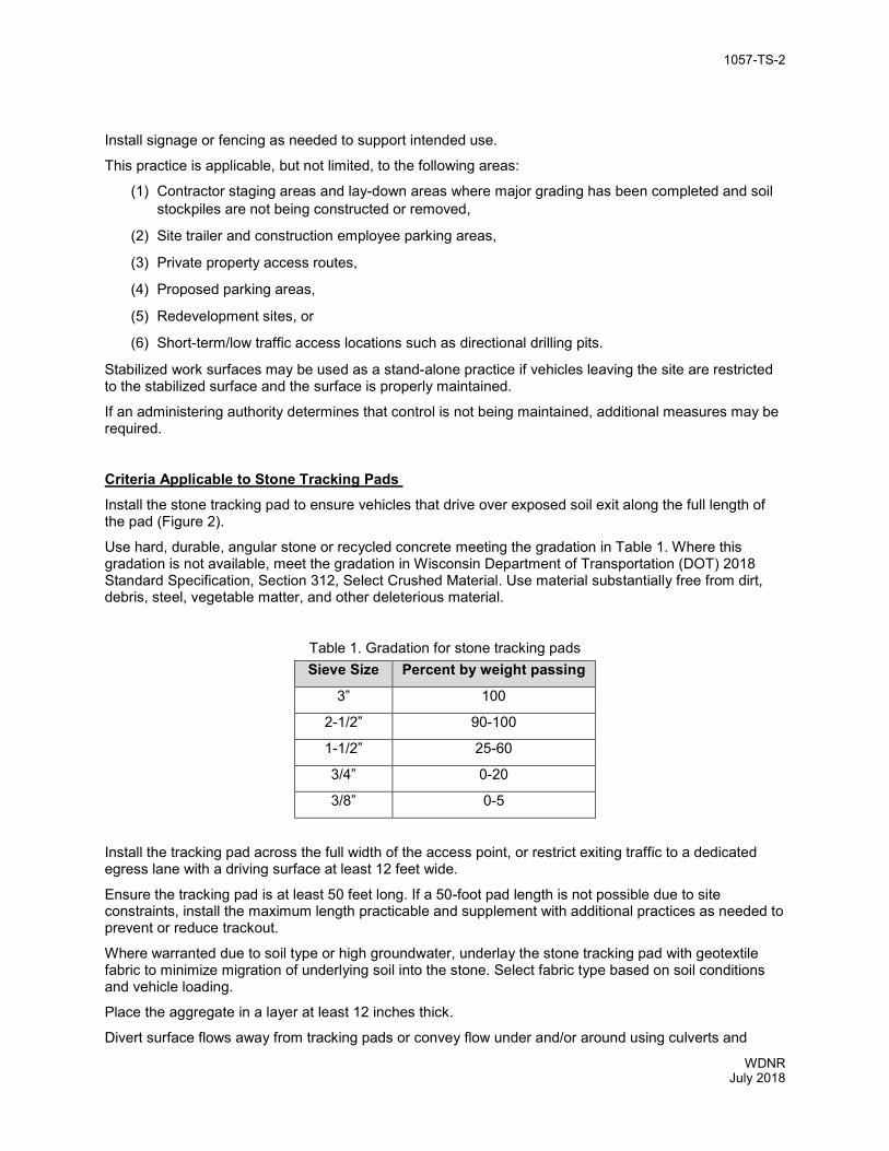
1057-TS-2
WDNR July 2018
Install signage or fencing as needed to support intended use.
This practice is applicable, but not limited, to the following areas:
(1) Contractor staging areas and lay-down areas where major grading has been completed and soil stockpiles are not being constructed or removed,
(2) Site trailer and construction employee parking areas,
(3) Private property access routes,
(4) Proposed parking areas,
(5) Redevelopment sites, or
(6) Short-term/low traffic access locations such as directional drilling pits.
Stabilized work surfaces may be used as a stand-alone practice if vehicles leaving the site are restricted to the stabilized surface and the surface is properly maintained.
If an administering authority determines that control is not being maintained, additional measures may be required.
Criteria Applicable to Stone Tracking Pads Install the stone tracking pad to ensure vehicles that drive over exposed soil exit along the full length of the pad (Figure 2).
Use hard, durable, angular stone or recycled concrete meeting the gradation in Table 1. Where this gradation is not available, meet the gradation in Wisconsin Department of Transportation (DOT) 2018 Standard Specification, Section 312, Select Crushed Material. Use material substantially free from dirt, debris, steel, vegetable matter, and other deleterious material.
Table 1. Gradation for stone tracking pads Sieve Size Percent by weight passing
3” 100
2-1/2” 90-100
1-1/2” 25-60
3/4” 0-20
3/8” 0-5
Install the tracking pad across the full width of the access point, or restrict exiting traffic to a dedicated egress lane with a driving surface at least 12 feet wide.
Ensure the tracking pad is at least 50 feet long. If a 50-foot pad length is not possible due to site constraints, install the maximum length practicable and supplement with additional practices as needed to prevent or reduce trackout.
Where warranted due to soil type or high groundwater, underlay the stone tracking pad with geotextile fabric to minimize migration of underlying soil into the stone. Select fabric type based on soil conditions and vehicle loading.
Place the aggregate in a layer at least 12 inches thick.
Divert surface flows away from tracking pads or convey flow under and/or around using culverts and

1057-TS-3
WDNR July 2018
swales. Direct runoff from tracking pads to sediment control practices.
Do not compact aggregate prior to use. Compaction, grouting, or other means of creating a smooth surface compromise the effectiveness of the tracking pad.
Remove stones lodged between the tires of dual wheel vehicles prior to leaving the construction site.
Criteria Applicable to Manufactured Trackout Control Devices
Install the manufactured trackout control device on a surface capable of supporting anticipated loads per manufacturer recommendations (Figure 3).
Situate the device to ensure vehicles that drive over exposed soil exit across the full length of the device. Provide a minimum device length of 32 feet for stand-alone installations. Add length if needed to reduce trackout in adverse conditions.
Criteria Applicable to Tire Washing Select the type of washing station based on project conditions and water availability. If a wash rack is used, select a rack capable of supporting the vehicle loading.
Install the washing station on site in a stabilized area. If the device discharges untreated water, direct wash water to a sediment basin designed per the current Technical Standard 1064, Sediment Basin, or an equivalent device. Follow the current Technical Standard 1051, Water Application of Additives for Sediment Control, for flocculants used at the tire washing station. Return sediment collected in the sediment basin to the site or dispose of appropriately.
Direct vehicles that drive over exposed soil to exit through the station.
This practice may be applicable, but not limited, to the following areas:
(1) Areas with prolonged periods or significant quantity of hauling on or off site, or
(2) Sites which drain to a sensitive resource such as an Outstanding Resource Water or Exceptional Resource Water.
Perform tire washing per manufacturer’s directions until the majority of sediment is removed from the tires.
Criteria Applicable to Street/Pavement Cleaning Scrape and/or sweep pavements and gutters until a shovel-clean or broom-clean condition is obtained. Repeat as needed to maintain public safety and reduce sediment delivery to drainage infrastructure or water resources, and at the end of each work day.
Use available equipment or select equipment per the recommendations in Table 2.
Return sediment to the site or dispose of appropriately.
CONSIDERATIONS
(1) An extended stabilized work surface such as a 150-foot long aggregate driveway within the site may be used as trackout control if sediment control is provided along the portions of driveways subject to sediment accumulation.
(2) Other methods of trackout control may be utilized if they do not generate dust or result in discharge of untreated water to drainage infrastructure or water resources.

1057-TS-4
WDNR July 2018
(3) Manual removal of sediment from vehicles may be needed when working in heavy mud cannot be avoided.
(4) Implement traffic guidance (e.g., signs, barriers, fences, flags) to restrict exiting traffic to the trackout device and prevent the circumvention of unfamiliar devices.
(5) Inform drivers of device weight limits and the location of alternate stabilized egress for oversized and/or overweight loads.
(6) Document in the erosion control plan whether stabilized impervious surfaces, such as staging areas, are temporary or permanent. Post-construction performance standards may apply in accordance with s. NR 151.121-128 or s. NR 151-421-249 Wis. Adm. Code.
(7) Vehicles traveling across trackout control practices should maintain a slow constant speed.
(8) Extend the tracking control length and/or implement additional trackout control practices to supplement primary control measures during major hauling operations, in heavy clay soils, or when conditions render the practice insufficient.
(9) All trackout control practices, especially stone tracking pads, generally need more maintenance during and immediately after completion of major hauling operations.
(10) If known soil and/or groundwater contamination is present on site as documented on the Bureau for Remediation and Redevelopment Tracking System (BRRTS on the Web) or has been identified through activities on site, then the potential for contamination transport should be assessed. If contamination is identified, impacted soil or water should be characterized and stored, treated or disposed of in compliance with applicable standards and rules. If this is a new contaminant release, consult Wisconsin Department of Natural Resources (DNR) staff in the regional Remediation and Redevelopment Program.
(11) Methods of street cleaning vary based on project size, conditions, and availability of equipment. These methods require the contractor to follow OSHA standards for silica dust control and may require additional safeguards to meet current standards.

1057-TS-5
WDNR July 2018
Table 2. Street cleaning methods Method
Effective for: Notes
Larger clumps
Wet Dry Sand Clay/Silt Minimizing dust
Shovel and broom by hand
Yes Yes Yes Yes Yes Yes Good for incidental tracking from low traffic sites or minor accumulations.
Power angle broom
Yes Yes Yes, with dust control
Yes Yes Less effective, but better with dust control
Harder to control collection of debris.
Power pick up broom
Yes Yes Yes, with dust control
Yes Yes Yes, with dust control
Generally will not get close to edges without a gutter broom, which is less effective. Use in reverse to maximum effects. Better dust control than angle broom.
Traditional street sweeper
Yes Yes Yes, with dust control
Yes Yes
Yes, with dust control
May not be cost effective for low traffic sites. Better dust control than an angle broom.
High efficiency sweeper (vacuum or regenerative air)
No No Yes Yes Dry – Yes
Wet – No
Yes May not be cost effective for low traffic sites. Presents difficulties with larger material. Best option for dust control.
PLANS AND SPECIFICATIONS Address the following in plans and specification:
(1) Location, materials, and dimensions of all stabilized work surfaces,
(2) Location of all points of egress with all trackout control practices shown,
(3) Material specifications conforming to this standard,
(4) Sequence or schedule for installation and removal of practices through different phases of construction; clearly indicate if stabilized work surfaces are temporary or permanent,
(5) Standard drawings and installation, and
(6) Stabilization after removal.
Include the responsible party by name, or by title if not known (e.g., general contractor, land owner). Include the frequency of inspection and maintenance in plans, standard detail drawings, or specifications.
Amend onsite erosion control plans to reflect modifications during the life of the project, including relocation or addition of site entrances and exits.
OPERATION AND MAINTENANCE Monitor all trackout control practices and nearby streets and roads at least daily during construction and more frequently during heavy use.
Clean and maintain all practices as needed to minimize trackout.

1057-TS-6
WDNR July 2018
Accumulation of sediment on off-site pavement near a site exit is an indication that street cleaning is needed and on-site prevention and control measures need maintenance or are not adequate. Relocate or add practices when construction egress locations are changed or when current control measures are not reducing trackout.
Clean streets and roads as needed to maintain traction, minimize further spread of sediment, and reduce discharge to drainage infrastructure.
Clean trackout control devices, mats, and other reusable materials prior to transport to a new site to reduce the potential for spread of invasive species and minimize further spread of sediment.
Add signage, fencing, steel posts, and/or traffic barriers as needed to improve use of practices.
Stabilized Work Surface Monitor stabilized work surface areas for soil deposits, standing water, and damage. Remove soil deposits daily through scraping and/or pavement cleaning, and repair damage as needed. Top dress gravel surfaces as needed. Replace or repair torn or damaged mats.
Stone Tracking Pad Monitor tracking pads for compaction, soil deposits, and mixing of underlying soils and stone layers.
Maintain a loosened, rough surface by scraping, loosening, or top-dressing with additional aggregate.
Replace geotextile and stone if less-intensive maintenance efforts fail to reestablish effectiveness.
Add stone as needed to maintain the minimum pad thickness.
Replace damaged or crushed culverts under tracking pad.
Manufactured Trackout Control Device Monitor and maintain devices to minimize shifting, rutting of adjacent surfaces, and structural failure.
Remove accumulated sediment as required to maintain the function of the device.
Replace missing or damaged elements such as bars or anchors, and remove and reset devices if they shift during use.
Fill ruts in adjacent surfaces with aggregate or paving materials. Maintain a stable surface between the device and street or road. Tire Washing Monitor tire washing station for sediment accumulation, clogged hoses, appropriate water levels, and effectiveness.
Remove accumulated sediment.
Replenish flocculant as needed, and replace or replenish water as needed.
Maintain hoses to minimize clogging or freezing.
For manufactured tire washing stations, maintain per manufacturer’s recommendations.
Modify operations as needed during cold weather to minimize formation of ice-hazards on roadways.

1057-TS-7
WDNR July 2018
DEFINITIONS Aggregate: A composite mixture of hard, durable, mineral materials that have been mechanically processed.
Broom-clean: A pavement condition where no measurable material is collected when a push broom is pushed lightly across the surface. This is generally applicable in dry conditions.
Drainage infrastructure: Features present above or below grade for the purpose of collecting and transmitting storm water. These features include, but are not limited to, ditches, storm sewers, drainage inlets, flumes, and manholes.
Manufactured trackout control device: A device installed and maintained at an egress location for reducing trackout of sediments through flexing and vibrating tires.
Trackout: The relocation of material from its intended location to offsite surfaces by vehicles.
Shovel-clean: A pavement condition where no measurable material is collected when a flat-edged shovel is pushed across the surface. This is generally applicable in wet conditions.
Site: The area within the construction limits. Construction limits may change over the course of a project.
Vehicle: Cars, trucks, and other equipment capable of moving persons or property using tires or tracks.
REFERENCES Wisconsin Council on Forestry, Invasive Species Best Management Practices for Transportation and Utility Rights-of-Way, https://councilonforestry.wi.gov/Documents/InvasiveSpecies/ROW-Manual.pdf
Wisconsin DNR, Outstanding and Exceptional Resource Waters, http://dnr.wi.gov/topic/SurfaceWater/orwerw.html
Wisconsin DNR, Storm Water Construction Technical Standards, http://dnr.wi.gov/topic/stormwater/standards/const_standards.html
Wisconsin DNR, Storm Water Post-Construction Technical Standards, http://dnr.wi.gov/topic/stormwater/standards/postconst_standards.html
Wisconsin Department of Transportation, Select Crushed Material, 2018 Standard Specification, Section 312, http://wisconsindot.gov/rdwy/stndspec/ss-03-12.pdf

1057-TS-8
WDNR July 2018
Figure 1:
Example of a common setup that can be used to implement a stabilized surface area.

1057-TS-9
WDNR July 2018
Figure 2:
Stone tracking pad detail
Note 1 Use hard, durable, angular stone or recycled concrete meeting the gradation in Table 1. Where this gradation is not available, meet the gradation in Wisconsin Department of Transportation (DOT) 2018 Standard Specification, Section 312, Select Crushed Material. Note 2 Slope the stone tracking pad in a manner to direct runoff to an approved treatment practice. Note 3 Select fabric type based on soil conditions and vehicles loading. Note 4 Install tracking pad across full width of the access point, or restrict existing traffic to a dedicated egress lane at least 12 feet wide across the top of the pad. Note 5 If a 50’ pad length is not possible due to site geometry, install the maximum length practicable and supplement with additional practices as needed.

1057-TS-10
WDNR July 2018
Figure 3:
Example manufactured trackout control device detail.
Note 1 This detail is provided as an example. Comply with manufacturer’s specifications while also meeting the minimum manufactured tracking pad length and width described in this technical standard. Note 2 Install such that runoff flows to an approved treatment practice. Note 4 A thinner stone layer or other stable surface may be acceptable such that rutting is minimized as vehicles mount or dismount from the manufactured trackout control device. Note 5 Select fabric type based on soil conditions and vehicles loading. Note 6 Direct all exiting vehicles over manufactured trackout control device. Stone tracking pad installation across remaining access width is recommended. A 12’ minimum can be used when exiting traffic is restricted to a dedicated egress lane. Note 7 If minimum installation length is not possible due to site geometry, install the maximum length practicable and supplement with additional practices as needed. Note 7 Accommodate exiting vehicles in excess of manufactured trackout control device weight capacity with other treatment practices.

Mulching For Construction Sites
(1058)
Wisconsin Department of Natural Resources Technical Standard
I. Definition
Mulching is the application of organic material to the soil surface to protect it from raindrop impact and overland flow. Mulch covers the soil and absorbs the erosive impact of rainfall and reduces the flow velocity of runoff.
II. Purpose
This practice may be used to:
• Reduce soil erosion • Aid in seed germination and establishment
of plant cover • Conserve soil moisture
III. Conditions Where Practice Applies
This practice may be applied on exposed soils as a temporary control where soil grading or landscaping has taken place or in conjunction with temporary or permanent seeding. Mulching is generally not appropriate in areas of concentrated flow.
IV. Federal, State, and Local Laws
Users of this standard shall comply with applicable federal, state and local laws, rules, regulations or permit requirements governing mulching. This standard does not contain the text of federal, state, or local laws.
V. Criteria
This section establishes the minimum standards for design, installation and performance requirements.
A. Site Preparation:
Soil surface shall be prepared prior to the application of mulch in order to achieve the desired purpose and to ensure optimum contact between soil and mulch. All areas to be mulched shall be reasonably free of rills and gullies.
B. Materials:
Mulch shall consist of natural biodegradable material such as plant residue (including but not limited to straw, hay, wood chips, bark and wood cellulose fiber), or other equivalent materials of sufficient dimension (depth or thickness) and durability to achieve the intended effect for the required time period.
Mulch shall be environmentally harmless to wildlife and plants. Materials such as gravel, plastic, fabric, sawdust, municipal solid waste, solid waste byproducts1, shredded paper, and non-biodegradable products shall not be used.
Mulch shall be free of diseased plant residue (i.e. oak wilt), noxious weed seeds, harmful chemical residues, heavy metals, hydrocarbons and other known environmental toxicants.
Marsh hay shall not be used as mulch in lowland areas but may be used on upland sites to prevent the spread of invasive, non- native species (i.e. reed canary grass) commonly found in marsh hay.
Straw and hay mulch that will be crimped shall have a minimum fiber length of 6 inches.
Technical Standards are reviewed periodically and updated if needed. To obtain the current version of WDNR this standard, contact your local WDNR office or the Standards Oversight Council office in Madison, WI at (608) 441-2677. 06/03
1 Words in the standard that are shown in italics are described in X. Definitions. The words are italicized the first time they are used in the text.

2 WDNR
06/03
Wood chips or wood bark shall only be used for sites that are not seeded.
C. Application Rate:
1. Mulch shall cover a minimum of 80% of
the soil surface for unseeded areas. For seeded areas, mulch shall be placed loose and open enough to allow some sunlight to penetrate and air to circulate but still cover a minimum of 70% of the soil surface.
2. Mulch shall be applied at a uniform rate
of 1½ to 2 tons per acre for sites that are seeded, and 2 to 3 tons per acre for sites that are not seeded. This application results in a layer of ½ to 1½ inches thick for seeded sites, and 1½ to 3 inches thick for sites not seeded.
3. Wood chips or wood bark shall be
applied at a rate of 6 to 9 tons per acre to achieve a minimum of 80% ground cover. This application should result in a layer of wood chips or wood bark ½ to 1½ inches thick.
D. Mulch Anchoring Methods
Anchoring of mulch shall be based on the type of mulch applied, site conditions, and accomplished by one of the following techniques:
1. Crimping
Immediately after spreading, the mulch shall be anchored by a mulch crimper or equivalent device consisting of a series of dull flat discs with notched edges spaced approximately 8 inches apart. The mulch shall be impressed in the soil to a depth of 1 to 3 inches.
2. Polypropylene Plastic, or Biodegradable
Netting
Apply plastic netting over mulch application and staple according to manufacturer’s recommendations.
3. Tackifier
Tackifier shall be sprayed in conjunction with mulch or immediately
after the mulch has been placed. Tackifiers must be selected from those that meet the WisDOT Erosion Control Product Acceptability List (PAL). Asphalt based products shall not be applied.
The tackifiers shall be applied at the following minimum application rates per acre:
a. Latex-Base: mix 15 gallons of
adhesive (or the manufacturer’s recommended rate which ever is greater) and a minimum of 250 pounds of recycled newsprint (pulp) as a tracer with 375 gallons of water.
b. Guar Gum: mix 50 pounds of dry
adhesive (or the manufacturer’s recommended rate which ever is greater) and a minimum of 250 pounds of recycled newsprint (pulp) as tracer with 1,300 gallons of water.
c. Other Tackifiers: (Hydrophilic
Polymers) mix 100 pounds of dry adhesive (or the manufacturer’s recommended rate which ever is greater) and a minimum of 250 pounds of recycled newsprint (pulp) as a tracer with 1,300 gallons of water.
VI. Considerations A. Wood products typically absorb available
soil nitrogen as they degrade, thus making it unavailable for seed.
B. The use of mulch behind curb and gutter
may not be desirable unless anchored by netting, because air turbulence from nearby traffic can displace the mulch. Consider the use of erosion mat or sod as an alternative.
C. In areas where lawn type turf will be
established, the use of tackifiers is the preferred anchoring method. Crimping will tend to leave an uneven surface and plastic netting can become displaced and entangled in mowing equipment.

3 WDNR
06/03
D. A heavier application of mulch may be desired to prevent seedlings from being damaged by frost.
E. It may be beneficial to apply polyacrylimide
in addition to mulch. Refer to WDNR Technical Standard (1050) Erosion Control Land Application of Anionic Polyacrylamide for information about the advantages and proper use of polymers.
F. Concentrated flows above the site where
mulch is applied should be diverted.
G. Mulch should be placed within 24 hours of seeding.
H. Mulching operations should not be
performed during periods of excessively high winds that would preclude the proper placement of mulch.
I. Materials such as gravel may be effective
for erosion control but are not considered mulches.
VII. Plans and Specifications
A. Plans and specifications for mulching shall
be in keeping with this standard and shall describe the requirements for applying the practice to achieve its intended purpose. The plans and specifications shall address the following:
1. Type of mulch used
2. Application rate
3. Timing of application
4. Method of anchoring
B. All plans, standard detail drawings, or
specifications shall include schedules for installation, inspection, and maintenance. The responsible party shall be identified.
VIII. Operation and Maintenance
Mulch shall, at a minimum, be inspected weekly and within 24 hours after every precipitation event that produces 0.5 inches of rain or more during a 24-hour period.
Mulch that is displaced shall be reapplied and properly anchored. Maintenance shall be completed as soon as possible with consideration to site conditions. IX. References WisDOT’s Erosion Control Product Acceptability List (PAL) can be found on the WisDOT web site: https://wisconsindot.gov/Pages/doing-bus/eng-consultants/cnslt-rsrces/tools/pal/default.aspx Printed copies are no longer being distributed. X. Definitions Noxious weed (V.B): Any weed a governing body declares to be noxious within its respective boundaries. The State of Wisconsin list of noxious weeds can be found in Statute 66.0407. Solid Waste Byproducts (V.B): Includes industrial, commercial, residential, and agricultural wastes that have been processed, incinerated, or composted and still contain inorganic wastes such as glass and metals and organic wastes including plastics, textiles, rubber, leather, and other miscellaneous organic wastes which may be toxic or hazardous in nature.

Seeding For Construction Site Erosion Control (1059)
Wisconsin Department of Natural Resources
Technical Standard
I. Definition
Planting seed to establish temporary or permanent vegetation for erosion control.
II. Purpose
The purpose of temporary seeding1 is to reduce runoff and erosion until permanent vegetation or other erosion control practices can be established. The purpose of permanent seeding is to permanently stabilize areas of exposed soil.
Ill. Conditions Where Practice Applies
This practice applies to areas of exposed soil where the establishment of vegetation is desired. Temporary seeding applies to disturbed areas that will not be brought to final grade or on which land-disturbing activities will not be performed for a period greater than 30 days, and requires vegetative cover for less than one year. Permanent seeding applies to areas where perennial vegetative cover is needed.
IV. Federal, State and Local Laws
Users of this standard shall be aware of all applicable federal, state and local laws, rules, regulations or permit requirements governing seeding. This standard does not contain the text of federal, state or local laws.
V. Criteria
This section establishes the minimum standards for design, installation and performance requirements.
A. Site and Seedbed Preparation
Site preparation activities shall include:
1. Temporary Seeding
a. Temporary seeding requires a seedbed of loose soil to a minimum depth of 2 inches.
b. Fertilizer application is not
generally required for temporary seeding. However, any application of fertilizer or lime shall be based on soil testing results.
c. The soil shall have a pH range of
5.5 to 8.0. 2. Permanent Seeding
a. Topsoil installation shall be completed prior to permanent seeding.
b. Permanent seeding requires a
seedbed of loose topsoil to a minimum depth of 4 inches with the ability to support a dense vegetative cover.
c. Application rates of fertilizer or
lime shall be based on soil testing results.
d. Prepare a tilled, fine, but firm
seedbed. Remove rocks, twigs foreign material and clods over two inches that cannot be broken down.
e. The soil shall have a pH range of
5.5 to 8.0.
Technical Standards are reviewed periodically and updated if needed. To obtain the current version of WDNR this standard, contact your local WDNR office or the Standards Oversight Council office in Madison, WI at (608) 441-2677. 11/03
1 Words in the standard that are shown in italics are described in X. Definitions. The words are italicized the first time they are used in the text.

WDNR, WI 11/03
2
Species Lbs/Acre Percent Purity Oats 1311
98 Cereal Rye 1312
97 Winter wheat 1312
95 Annual Ryegrass 802
97
B. Seeding
1. Seed Selection
a. Seed mixtures that will produce dense vegetation shall be selected based on soil and site conditions and intended final use. Section IX References, lists sources containing suggested seed mixtures.
b. All seed shall conform to the
requirements of the Wisconsin Statutes and of the Administrative Code Chapter ATCP 20.01 regarding noxious weed seed content and labeling.
c. Seed mixtures that contain
potentially invasive species or species that may be harmful to native plant communities shall be avoided.
d. Seed shall not be used later than
one year after the test date that appears on the label.
e. Seed shall be tested for purity,
germination and noxious weed seed content and shall meet the minimum purity and germination requirements as prescribed in the current edition of Rules for Testing Seed, published by the Association of Official Seed Analysts.
2. Seed Rates
a. Temporary Seeding (Cover Crop)
Areas needing protection during periods when permanent seeding is not applied shall be seeded with annual species for temporary protection. See Table 1 for seeding rates of commonly used species. The residue from this crop may either be incorporated into the soil during seedbed preparation at the next permanent seeding period or left on the soil surface and the planting made as a no-till seeding.
Table 1 Temporary Seeding Species and Rates
1 Spring and summer seeding 2 Fall seeding
b. Permanent Seeding
Rates shall be based on pounds or ounces of Pure Live Seed (PLS) per acre. Section IX contains some possible reference documents that provide seeding rates. Permanent seeding rates may be increased above the minimum rates shown in the reference documents to address land use and environmental conditions.
If a nurse crop is used in conjunction with permanent seeding, the nurse crop shall not hinder establishment of the permanent vegetation.
A nurse crop shall be applied at 50% its temporary seeding rate when applied with permanent seed.
3. Inoculation
Legume seed shall be inoculated in accordance with the manufacturer’s recommendations. Inoculants shall not be mixed with liquid fertilizer.
4. Sowing
Seed grasses and legumes no more than ¼ inch deep. Distribute seed uniformly. Mixtures with low seeding rates require special care in sowing to achieve proper seed distribution.
Seed may be broadcast, drilled, or hydroseeded as appropriate for the site.
Seed when soil temperatures remain consistently above 53° F. Dormant seed when the soil temperature is consistently below 53° F (typically

WDNR, WI 11/03
3
Nov. 1st until snow cover). Seed shall not be applied on top of snow.
VI. Considerations
A. Consider seeding at a lower rate and making
two passes to ensure adequate coverage.
B. Compacted soil areas may need special site preparation prior to seeding to mitigate compaction. This may be accomplished by chisel plowing to a depth of 12 inches along the contour after heavy equipment has left the site.
C. Sod may be considered where adequate
watering is available.
D. When working in riparian areas refer to the NRCS Engineering Field Handbook, Chapter 16, Streambank and Shoreline Protection and Chapter 18, Soil Bioengineering for Upland Slope Protection and Erosion Reduction.
E. A site assessment should be conducted to
evaluate soil characteristics, topography, exposure to sunlight, proximity to natural plant communities, proximity to nuisance, noxious and/or invasive species, site history, moisture regime, climatic patterns, soil fertility, and previous herbicide applications.
F. Use introduced species only in places where
they will not spread into existing natural areas.
G. Lightly roll or compact the area using
suitable equipment when the seedbed is judged to be too loose, or if the seedbed contains clods that might reduce seed germination.
H. See Section IX. References for suggested
seed mixes (NRCS, WisDOT, UWEX) or use their equivalent.
I. Turf seedlings should not be mowed until
the stand is at least 6 inches tall. Do not mow closer than 3 inches during the first year of establishment.
J. Seeding should not be done when the soil is
too wet.
K. Consider watering to help establish the seed. Water application rates shall be controlled to prevent runoff and erosion.
L. Prairie plants may not effectively provide
erosion control during their establishment period without a nurse crop.
M. Topsoil originating from agricultural fields
may contain residual chemicals. The seedbed should be free of residual herbicide or other contaminants that will prevent establishment and maintenance of vegetation. Testing for soil contaminants may be appropriate if there is doubt concerning the soil’s quality.
N. Consider using mulch or a nurse crop if
selected species are not intended for quick germination. When mulching refer to WDNR Technical Standard Mulching for Construction Sites (1058).
VIl. Plans and Specifications Plans and specifications for seeding shall be in keeping with this standard and shall describe the requirements for applying this practice. All plans, standard detail drawings, or specifications shall include schedule for installation, inspection, and maintenance. The responsible party shall be identified. VlIl. Operation and Maintenance A. During construction areas that have been
seeded shall at a minimum be inspected weekly and within 24 hours after every precipitation event that produces 0.5 inches of rain or more during a 24-hour period. Inspect weekly during the growing season until vegetation is densely established or permit expires. Repair and reseed areas that have erosion damage as necessary.
B. Limit vehicle traffic and other forms of
compaction in areas that are seeded. C. A fertilizer program should begin with a soil
test. Soil tests provide specific fertilizer recommendations for the site and can help to avoid over-application of fertilizers.

WDNR, WI 11/03
4
IX. References
A. Seed Selection References
United States Department of Agriculture – Natural Resources Conservation Service Field Office Technical Guide Section IV, Standard 342, Critical Area Planting.
UWEX Publication A3434 Lawn and Establishment & Renovation.
WisDOT, 2003. State of Wisconsin Standard Specifications For Highway and Structure Construction. Section 630, Seeding.
B. General References
Association of Official Seed Analysts, 2003. Rules for Testing Seed. http://www.aosaseed.com.
Metropolitan Council, 2003. Urban Small Sites Best Management Practice Manual, Chapter 3, Vegetative Methods 3-85 – 3-91. Minneapolis.
The State of Wisconsin list of noxious weeds can be found in Statute 66.0407.
United States Department of Agriculture – Natural Resources Conservation Service. Engineering Field Handbook, Chapters 16 and 18.
UWEX Publication GWQ002 Lawn & Garden Fertilizers.
X. Definitions
Dense (V.A.2.b) A stand of 3-inch high grassy vegetation that uniformly covers at least 70% of a representative 1 square yard plot.
Dormant seed (V.B.4): Seed is applied after climatic conditions prevent germination until the following spring.
Introduced Species (VI.F) Plant species that historically would not have been found in North America until they were brought here by travelers from other parts of the world. This would include smooth bromegrass and alfalfa. Some of these species may have a wide distribution such as Kentucky bluegrass.
Nurse Crop (V.B.2.b): Also known as a companion crop; is the application of temporary (annual) seed with permanent seed. Permanent seeding (II) Seeding designed to minimize erosion for an indefinite period after land disturbing construction activities have ceased on the site. Soil Bioengineering (VI.D) Practice of combining mechanical, biological and ecological concepts to arrest and prevent shallow slope failures and erosion. Temporary Seeding (II) Seeding designed to control erosion for a time period of one year or less that is generally removed in order to perform further construction activities or to permanently stabilize a construction site. Topsoil (V.A.2.a) Consists of loam, sandy loam, silt loam, silty clay or clay loam humus-bearing soils adapted to sustain plant life with a pH range of 5.5 – 8.0. Manufactured topsoil shall through the addition of sand or organic humus material, peat, manure or compost meet the above criteria.

Technical Standards are reviewed periodically and updated if needed. To obtain the current version of this standard, contact your local WDNR office or the Standards Oversight Council office in Madison, WI at (608) 441-2677.
WDNR November 2017
WISCONSIN DEPARTMENT OF NATURAL RESOURCES TECHNICAL STANDARD
DUST CONTROL ON CONSTRUCTION SITES 1068
DEFINITION Dust control includes practices used to reduce or prevent the surface and air transport of dust during construction.
Dust control measures for construction activities include minimization of soil disturbance, applying mulch and establishing vegetation, water spraying, surface roughening, applying additives (polymers), spray-on tackifiers, chlorides, and barriers.
PURPOSE This practice may be used to:
(1) Reduce wind erosion and dust.
(2) Minimize deposition of dust and wind transported soils into water bodies through runoff or wind action.
(3) Reduce respiratory problems.
(4) Minimize low visibility conditions caused by airborne dust.
CONDITIONS WHERE PRACTICE APPLIES Dust control measures may be applied at any construction site, but is particularly important for sites with dry exposed soils which may be exposed to wind or vehicular traffic.
CRITERIA Comply with applicable federal, state and local laws, rules, regulations or permit requirements governing this practice. This standard does not contain the text of federal, state, or local laws.
This section establishes the minimum standards for design, installation and performance requirements.
Limit the area exposed for dust generation prior to implementing dust control practices.
Asphalt and petroleum based products cannot be used for dust control.
Mulch and Vegetation. Mulch or seed and mulch may be applied to protect exposed soil from both wind and water erosion. Refer to WDNR Technical Standards Mulching for Construction Sites (1058) and Seeding for Construction Site Erosion Control (1059) for criteria.
Water. Water until the surface is wet and repeat as needed. Water at rates so that runoff does not occur. Provide a stone tracking pad or tire washing station at treated soil surfaces that receive vehicle traffic. Refer to WDNR Technical Standard Stone Tracking Pad and Tire Washing (1057) for criteria.
Tillage. Tillage can be used as a control measure performed with chisel type plows on exposed soils. Begin tillage on the windward side of the site. Tillage is only applicable to flat areas.
Additives. Additives can be an effective practice for areas that do not receive vehicle traffic. Initially apply water to additives for activation to be effective for dust control. Refer to WDNR Technical Standard 1050 - Land Applied Additives for Erosion Control for application criteria.

1068-TS-2
WDNR November 2017
Tackifiers and Soil Stabilizers Type A. Select products and install at rates conforming to the WisDOT Erosion Control Product Acceptability List (PAL). Examples include vegetable based products such as natural Latex or Guar Gum.
Chlorides. Apply chlorides according to the most recent version of the WisDOT Standard Specifications for Highway and Bridge Construction.
Barriers. Place barriers at right angles to prevailing wind currents at intervals of about 15 times the barrier height. Solid board fences, snow fences, burlap fences, crate walls, bales of hay and similar material can be used to control air currents and blown soil.
CONSIDERATIONS Some sites may require an approach that utilizes a combination of measures for dust control.
PLANS AND SPECIFICATIONS Prepare plans and specifications for dust control practices in keeping with this standard and to describe the requirements for applying the practice to achieve its intended purpose.
OPERATION AND MAINTENANCE Inspect daily areas that have dust control practices.
REFERENCES WisDOT’s Erosion Control Product Acceptability List (PAL) can be found on the WisDOT web site: http://wisconsindot.gov/Pages/doing-bus/eng-consultants/cnslt-rsrces/tools/pal/default.aspx Printed copies are no longer being distributed.

Turbidity Barrier (1069)
Wisconsin Department of Natural Resources
Technical Standard
I. Definition
A temporary fabric barrier with very low permeability, installed in or near the bed of a waterway or waterbody to minimize sediment transport and is installed parallel to flow. Turbidity barrier cannot be installed perpendicular to a moving channel.
II. Purposes
The purpose of this practice is to provide sediment containment while construction activities are occurring in or directly adjacent to a waterway or waterbody.
III. Conditions Where Practice Applies
This practice applies where construction activities intrude or are directly adjacent to a waterway or waterbody. This includes but is not limited to bridge construction, rip rap placement, utility work, streambank restoration, boat launches and dredging.
Use turbidity barriers in conditions with fine soils and flow velocities not exceeding 5 feet per second, unless additional reinforcement is installed.
IV. Federal, State, and Local Laws
Users of this standard shall be aware of applicable federal, state, and local laws, rules, regulations, or permit requirements governing the use and placement of turbidity barriers. This standard does not contain the text of federal, state, or local laws.
V. Criteria
This section establishes the minimum standards for design, installation and performance requirements.
A. Installation – Details of construction not listed
in the text shall conform to the pertinent requirements of Figures 1 and 2.
1. The barrier shall be installed before
construction activities are initiated in, or
adjacent to the waterway or waterbody. Install the turbidity barrier as close to the construction as practical. The barrier shall remain in place and be maintained until the construction activity is completed and the disturbed area stabilized 1.
2. The ends of the barrier shall be securely
anchored and keyed into the shoreline to fully enclose the area where sediment may enter the water.
3. Driven steel posts shall be used to hold the
barrier in position. The maximum spacing between posts shall be 10 feet. When barrier height exceeds 8 feet, post spacing may need to be decreased.
When bedrock prevents the installation of posts, float devices may be used. Flotation devices shall be flexible, buoyant units contained in an individual flotation sleeve or collar attached to the turbidity barrier. Use solid expanded polystyrene logs or equivalent having a 49 square inch minimum end area. Do not use polystyrene beads or chips. Buoyancy provided by the flotation devices shall be sufficient to support the weight of the turbidity barrier and maintain a freeboard of at least three inches above the water surface. Refer to Figure 1.
4. The barrier and steel posts shall extend from
the bottom of the waterway or waterbody to an elevation 2 feet above the anticipated high water level during the time of year and duration the barrier will be in place. The elevation shall not exceed the top of bank.
5. Ballast shall be used to hold the barrier in a
vertical position. Bottom load lines shall consist of a chain incorporated into the bottom hem of the screen, of sufficient weight to serve as ballast to hold the screen in a vertical position. Additional anchorage shall be provided if necessary.
Technical Standards are reviewed periodically and updated if needed. To obtain the current version of WDNR this standard, contact your local WDNR office or the Standards Oversight Council office in Madison, WI. 9/05
1 Words in the standard that are shown in italics are described in X. Definitions. The words are italicized the first time they are used in the text.

9/05
Requirement Method Value Min. grab tensile strength
ASTM D 4632
200 lb (890 N)
Min. puncture strength
ASTM D 4833
90 lb (400 N)
Maximum permeability
ASTM D 4491
-7 ≤ 1X10 cm/s
Min. ultraviolet stability
ASTM D 4355 70%
6. Danger buoys shall be used as directed by
the Coast Guard or DNR permit when working in navigable waters.
7. Turbidity barriers shall be installed parallel
to the direction of flow and shall not be installed across channels.
B. Material
1. Reusable components of the turbidity barrier
system shall be clean and free of potential exotic species. Fabric cannot be reused.
2. Top load lines shall consist of 5/16 inch
steel cable.
3. Fabric shall be selected according to the specifications in Table 1.
Table 1
Source: WisDOT Spec 628.2.10.
VI. Considerations
A. The 5 feet per second flow velocity specified in Section III can be the base flow of the stream or the base flow plus the addition of storm event runoff. Base flow can be used alone for short term projects (typically one day duration, i.e. culvert installation) when the chance of precipitation is low. Longer term projects (i.e. bridge work) should consider storm flow in addition to base flow (typically the two year event).
B. If the current exceeds 5 feet per second, other
methods to divert flow away from the turbidity barrier such as temporary concrete traffic barriers, coffer dams, pumping, or sheet piling should be considered.
C. Sediment that has been settled out by the
turbidity barrier should only be removed if so directed by the regulatory authority because re-
suspension of sediment will likely occur during the removal process. Use of polymers may help prevent resuspension of sediment. See WDNR Technical Standard 1051 Sediment Control Water Application of Polymers for further guidance.
D. Turbidity barriers are meant to manage sediment
in the waterbody. The best way to prevent sediment from entering the waterbody is through the implementation of effective upland erosion control, stopping sediment transport at its source.
E. Turbidity barriers should not be used to reduce
the conveyance capacity of the channel. An example is use on bridge projects where the turbidity barrier is installed adjacent to each abutment simultaneously.
F. Turbidity barriers may be installed on the banks
of a waterway or waterbody if higher water levels are anticipated during construction.
VII. Plans and Specifications Plans and specifications for installing a turbidity barrier shall be in keeping with this standard and attached detail drawing and shall describe the requirements for applying the practice to achieve its intended purpose: A. Location of turbidity barrier.
B. Material specification conforming to standard.
C. All plans, standard detail drawings, or specifications shall include schedule sequence or notes for installation, inspection, and maintenance. The responsible party shall be identified.
VIII. Operation and Maintenance A. Turbidity barriers shall be inspected daily and
repaired if necessary. B. Turbidity barriers shall not be removed until the
water behind the barrier has equal or greater clarity than the waterway or waterbody.
C. Care shall be taken when removing the barrier to
minimize the release or re-suspension of accumulated sediment.
D. To prevent the spread of exotic species turbidity
barriers shall not be reused on other sites. Buoys
2 WDNR

9/05
and chains can be reused but shall be either disinfected with vinegar or cleaned with hot water greater than 104 deg. F then allowed to completely dry for a minimum period of five days. If there are any questions about the occurrence of zebra mussels, Eurasian water- milfoil, or other aquatic invasive species in a waterbody that you are working in, or intend to work in, contact your local DNR staff.
IX. References
WisDOT Facilities Development Manual: Chapter 10, Section 10, Subject 45, Turbidity Barrier
X. Definitions
Stabilized (V.A.1): Means that all land disturbing construction activities at the construction site have been completed, and that a uniform perennial vegetative cover has been established with a density of at least 70% of the cover for the unpaved areas and areas not covered by permanent structures, or that employ equivalent stabilization measures.
WDNR 3

TURBIDITY BARRIER STANDARD POST INSTALLATION
2' MIN.
ANCHOR
DETAILS OF CONSTRUCTION, MATERIALS AND WORKMANSHIP NOT SHOWN ON THIS DRAWINGSHALL CONFORM TO THE PERTINENT REQUIREMENTS OF THE STANDARD ANDTHE APPLICABLE SPECIAL PROVISIONS
DRIVEN STEEL POSTS, PIPES, OR CHANNELS. LENGTH SHALL BE SUFFICIENTTO SECURELY SUPPORT BARRIER AT HIGH WATER ELEVATIONS.
SANDBAGS TO BE USED AS ADDITIONAL BALLAST WHEN ORDERED BY THE ENGINEER ORPROJECT MANAGER TO MEET ADVERSE FIELD CONDITIONS. SPACE AS APPROPRIATEFOR SITE CONDITIONS.
WHEN BARRIER HEIGHT, H, EXCEEDS 8 FT., POST SPACING MAY NEED TO BE DECREASED.
IN WATERWAYS SUBJECT TO FLUCTUATING WATER ELEVATIONS, PROVISIONS SHOULD BEMADE TO ALLOW THE WATER TO EQUALIZE ON EACH SIDE OF THE BARRIER. THIS MAY BEACCOMPLISHED BY LEAVING A PORTION OF THE BARRIER OPEN ON THE UPSTREAM END.
GENERAL NOTES
PLAN VIEW
TURBIDITY BARRIER MAY BE REMOVED AT THE ENGINEERS OR PROJECT MANAGERSDISCRETION, WHEN PERMANENT EROSION CONTROL MEASURES HAVE BEEN ESTABLISHED.
FLOAT ALTERNATIVE WILL ONLY BE ALLOWED WITH WRITTEN APPROVAL OF THE ENGINEEROR PROJECT MANAGER, AND IS MEANT FOR LOCATIONS WHERE BED ROCK PREVENTS THEINSTALLATION OF POSTS.
ALLOW SUFFICIENT SLACK VERTICALLY AND HORIZONTALLY SO THAT SEDIMENT BUILD UPWILL NOT SEPARATE OR LOWER THE TURBIDITY BARRIER.
SAND BAGS(40 LB. MIN.)
USE AS DIRECTED BY COAST GUARD OR DNR PERMIT WHENWORKING IN NAVIGABLE WATERWAYS.
4' MAX.
7
ANCHOR
BUOY
BUOY
B B
TURBIDITY BARRIER FLOAT ALTERNATIVECAUTION - SEE NOTE 5
This drawing based on WisconsinDepartment of TransportationStandard Detail Drawing 8 E 11-2.
Figure 1. Turbidity Barrier Placement Details
AA
SECTION A-A
SECTION B-B
RIPRAP
RIPRAP
RIPRAP
RIPRAP
Wat
er F
low
BUOY7
7
7
7
7
7
BUOY
Wat
er F
low
BALLAST
BALLAST
ANCHOR
ANCHOR
ANCHOR
BUOY
SAND BAGS2
1
1
2SAND BAGS(40 LB. MIN.)
BALLAST
2' MIN.4' MAX.
2SAND BAGS(40 LB. MIN.)
BALLAST
DANGER BUOY(EXAMPLE)
DANGER BUOY(EXAMPLE)
SHORELINE
SHORELINE
4
3
WORK AREAFABRIC3
H
WORK AREAFABRIC
SAND BAGS(40 LB. MIN.)
ANCHOR
STREAMBED
STREAMBED
NORMAL WATERSURFACE ELEVATION
CABLE
CABLE
SURFACE WATER
FLOATATION LOG, ORAPPROVED EQUAL(49 SQ. IN. MIN. END AREA)
6
7
6
5
4
3
2
1
FLOATATION LOG, ORAPPROVED EQUAL
NOT TO SCALE2
10' MAX
ANCHOR
BUOY

THIS PAGE INTENTIONALLY LEFT BLANK

ROADWAY
BRIDGE ABUTMENT
BRIDGE ABUTMENT
STREAM BED
POSTS
C C
100' 100'
100' 100'
10'MAX.
FIGURE 2. TURBIDITY BARRIER DETAIL SHOWING
WAT
ER
FLO
W
SLOPE INTERCEPT SLOPE INTERCEPT
SLOPE INTERCEPT SLOPE INTERCEPT
PLAN VIEW
SECTION C-C
TURBIDITY BARRIER
FLOAT ALTERNATIVE WILL ONLY BE ALLOWED WITH WRITTENAPPROVAL OF THE ENGINEER OR PROJECT MANAGER AND ISMEANT FOR LOCATIONS WHERE BEDROCK PREVENTS THEINSTALLATION OF POSTS.
GENERAL NOTE
This Drawing is Based on WisconsinDepartment of TransportationStandard Detail Drawing 8 E 11-2.
TYPICAL PLACEMENT AT STRUCTURES
NOT TO SCALE

Project #00320024 Appendices © 2021 MSA Professional Services, Inc.
APPENDIX B 1
2
Soil Sampling 3
4

THIS PAGE INTENTIONALLY LEFT BLANK

Consensus-Based Sediment Quality Guidelines
Recommendations for Use & Application
December 2003Interim Guidance
RR-088
Note to User:The information in this guidance can be used for screening sediment quality data to help estimate the likelihood of toxicity. DNR staff, responsible parties and consultants should evaluate available information in order to make case-by-case investigative, remediation and management decisions for each site.
Any remedial action selected in accordance with Wis. Stats. 292 to address sediment contamination must comply with the Wis. Admin. Code ch. 700 through 754 rule series, in particular Wis. Admin. Code §§ 722.09 (2)(c) and (3).
The values presented in the Consensus Based Sediment Quality Guidelines (RR-088) could be used as cleanup standards by responsible parties, with department approval, if they meet the provisions of Wis. Admin. Code ch. 700 – 754 rule series.
In addition, site-specific standard development and/or performance standards are potential options, if the remedial actions would comply with Wis. Stat. ch. 292 and Wis. Admin. Code ch. 700 through 754 rule series.
Risk assessments for sediment remediation are governed by Wis. Admin. Code NR § 722.11. In the case of sediments, a risk assessment for sediment is only allowable if the department determines that compliance with the applicable environmental standards listed in Wis. Admin. Code § NR 722.09(2) will not be protective of public health, safety, welfare, and the environment, and a more stringent standard is needed.
The department’s Integrated Sediment Team in conjunction with the Contaminated Sediment External Advisory Group are currently working on guidance for developing cleanup standards for sediments.

II
GOVERNORJim Doyle
NATURAL RESOURCES BOARD
Trygve Solberg, ChairJames Tiefenthaler Jr., Vice Chair
Gerald O'Brien, SecretaryHerbert F. BehnkeHoward D. Poulson
Jonathan P. ElaStephen D. Willett
Wisconsin Department of Natural ResourcesBox 7921
Madison, WI 53707
Scott Hassett, SecretaryWilliam H. Smith, Deputy Secretary
Elizabeth Kluesner, Executive Assistant
The Wisconsin Department of Natural Resources provides equal opportunity in its employmentprograms, services, and functions under an Affirmative Action Plan. If you have any questions,please write to Equal Opportunity Office, Department of Interior, Washington, D.C. 20240.
This publication is available in alternative format (large print, Braille, audio tape, etc.) upon request.Please call 608-267-3543 for more information.
PDF Version III

III
Acknowledgments
Preparation of this guidance, Consensus - Based Sediment Quality Guidelines; Recommendations forUse & Application, was a joint effort of Regional and Central Office staff that are members of theDepartment of Natural Resource's Contaminated Sediment Standing Team.
The Contaminated Sediment Standing Team is sponsored by:
Bureau of Remediation and Redevelopment, Air and Waste Division
Bureau of Watershed Management, Water Division
Contaminated Sediment Standing Team Members:
Tom Aartilla Jim Hosch Liesa NiestaJim Amrhein Tom Janisch Kelly O'ConnorMargaret Brunette Jim Killian Jennie PelczarBill Fitzpatrick Ed Lynch Candy SchrankSteve Galarneau Paul Luebke Linda TalbotBob Grefe Al Nass Xiaochun Zhang
Guidance Status
This guidance will be updated as needed. Comments and concerns may be sent to “Guidance Revisions” – RR/5, WDNR, P.O. Box 7921, Madison, WI, 53707
Notice
This document is intended solely as guidance and does not contain any mandatoryrequirements except where requirements found in statute or administrative rule arereferenced. This guidance does not establish legal rights or obligations and is not finallydeterminative of any of the issues addressed. This guidance does not create any rightsenforceable by any party in litigation with the State of Wisconsin or the Department of NaturalResources. Any regulatory decisions made by the Department of Natural Resources will bemade by applying the governing statutes and administrative rules to the relevant facts.
IV
Consensus - Based Sediment Quality Guidelines; Recommendations for Use &Application
Table of Contents
1. Overview …………………………………………………………………………………………….12. Introduction…………………………………………………………………………………………..33. Recommendations on the Type of Sediment Quality Guidelines to be Used………………...44. The Uses of Sediment Quality Guidelines………………………………………………………..45. Considerations and Advantages of Using Consensus-Based Sediment Quality
Guidelines…………………………………………………………………….. …………………….66. Interpreting Guidelines Concentrations That Fall Between the Lower TEC and
Upper PEC Consensus-Based Effect Guideline Values………………………………………..87. Recommended Guidelines and Values to be Used in Sediment Quality Assessments …….98. Additional Considerations for Some Contaminants…………………………………………….109. Background or Reference Site Concentration Considerations in Using the
Effect-Based Sediment Quality Guidelines……………………………………………………...119.1 Metals and Silt/Clay Fraction Relationships………………………………………………..139.2 Nonpolar Organic Compound and Total Organic Carbon Relationships………………..14
10. Point of Application of the CBSQGs in the Bed Sediment…………………………………….1511. Other Approaches Being Used to Develop SQGs …………………………………………….16
Tables
Table 1. Recommended Sediment Quality Guideline Values for Metals and Associated Levels of Concern to be Used in Doing Assessments of Sediment Quality……………………17
Table 2. Recommended Sediment Quality Guideline Values for Polycyclic AromaticHydrocarbons (PAHs) and Associated Levels of Concern to be Used in Doing Assessmentsof Sediment Quality……………………………………………………………………………………18
Table 3. Recommended Sediment Quality Guideline Values for Polychlorinated Biphenyls(PCBs) and Chlorinated and Other Pesticides and Associated Levels of Concern to be Usedin Doing Assessments of Sediment Quality………………………………………………………..19
Table 4. Recommended Sediment Quality Guideline Values for Assorted Contaminantsand Associated Levels of Concern to be Used in Doing Assessments of SedimentQuality………………………………………………………………………………………………….20
References …………………………………………………………………………………………..21

V
Appendixes
Appendix A. Recommended Procedure for Calculating Mean Probable EffectQuotients (PEC Quotients) for Mixtures of Chemicals found at ContaminatedSediment Sites and Their Reliability of Predicting the Presence or Absence ofToxicity……………………………………………………………………………………………..25
Appendix B. Recommended Procedure for Calculating the Maximum ProbableBackground Concentration (MPBC) For a Metal or Organic Compound at Referenceor Background Sites…………………………………………………………………………….. 29
Appendix C. Notes On Dioxins and Furans…………………………………………………. 32
Appendix D. Calculation Table. Dry Weight Sediment Concentrations of OrganicCompounds Normalized to 1% TOC for Comparison with CBSQGs and Grain SizeNormalizations of Metals for Site-to-Site Comparisons ………………………………...……33
Appendix E. Identification of Contamination that Leads to Adverse Effects………………. 35

1
Consensus - Based Sediment Quality Guidelines; Recommendations for Use &Application
1. Overview
• Wisconsin DNR needs effects-based (i.e., empirical) sediment quality guidelines (SQGs) forcommonly found, in place contaminants to serve as benchmark values for making comparisons tothe concentrations of contaminant levels in sediments at sites under evaluation for variousreasons (e.g., NR 347 dredging projects, degree and extent studies, screening level ecologicalrisk assessments). There is a need for these values on lower assessment tiers and on a screeninglevel basis and for other objectives during different phases of a site assessment.
• In the last few years, a number of entities have generated effects-based SQGs for some of themore widely measured contaminant metal and organic chemical compounds. Most of theguidelines have focused on effects to benthic-dwelling species. Watershed program staff haveused some of the guidelines for evaluating sediment quality at initial or lower tiers in theassessment process for the sediment quality at sites.
• The most recent development in sediment quality guidelines is where the effect-levelconcentrations from several guidelines of similar narrative intent are combined through averagingto yield consensus-based lower and upper effect values for contaminants of concern (e.g.,MacDonald et al. 2000a). The consensus-based values have been evaluated for their reliability inpredicting toxicity in sediments by using matching sediment chemistry and toxicity data from fieldstudies. The results of the reliability evaluation showed that most of the consensus-based valuesfor individual contaminants provide an accurate basis for predicting the presence or absence oftoxicity (MacDonald et al. 2000a). To predict the toxicity for mixtures of various contaminants insediments, the concentration of each contaminant is divided by its corresponding probable effectconcentration (PEC). The resulting values are called PEC-Quotients (PEC-Q). The individualPEC-Qs are summed and divided by the number of PEC-Qs to yield a mean PEC-Q. Usingrelationships derived from existing databases, the mean PEC-Q value can be used to predict thetoxicity of a mixture of contaminants in a sediment sample. The appendix provides furtherexplanation and examples of calculating and combining PEC-Q values.
• The CBSQGs as developed only involve effects to benthic macroinvertebrate species. A largeamount of databases from toxicological research have established the cause and effect orcorrelations of sediment contaminants to benthic organism and benthic community assessmentendpoints. The guidelines do not consider the potential for bioaccumulation in aquatic organismsand subsequent food chain transfers and effects to humans or wildlife that consume the upperfood chain organisms. For the most part where noncarcinogenic or nonbioaccumulative organicchemicals are involved, the guidelines should be protective of human health and wildlifeconcerns. Where bioaccumulative compounds such as PCBs and methyl mercury are involved,protection of human health or wildlife-based endpoints could result in more restrictive sedimentconcentrations than contained in the CBSQGs. Where these bioaccumulative compounds areinvolved, the CBSQGs need to be used in conjunction with other tools, such as human health andecological risk assessments, bioaccumulation-based guidelines, bioaccumulation studies, and

2
tissue residue guidelines to evaluate the direct toxicity and upper food chain effects of thesecompounds. Food chain models will need to be used to estimate safe levels of contaminants insediments that will not result in accumulated levels in upper food chain organisms that exceedtoxicity and tissue reference values.
• There are a number of program needs and uses for sediment quality guidelines during a tieredassessment process for a site under investigation related to further investigative and managementdecisions. For consistency sake, we recommend that the consensus-based SQGs (CBSQGs) ascurrently developed by MacDonald et al. (2000a) be utilized in appropriate situations by allDepartment programs for screening sediment quality data to help estimate the likelihood oftoxicity, as staff evaluate the available information in order to make case-by-case investigative andmanagement decisions for a site. For chemicals for which CBSQGs are not available, werecommend utilizing the most reliable of other effects-based freshwater SQGs that have beenpublished in the scientific literature or developed by WDNR or other regulatory entities. In theSQG tables that follow, these latter values are included and identified as to source. In most cases,the guidelines will need to be backed by additional sampling and field studies at sites underinvestigation to support the guideline-predicted biological effects.
• The MacDonald et al. (2000a) CBSQGs have a lower (threshold effect concentration - TEC) andupper (probable effect concentration - PEC) effect level at which toxicity to benthic-dwellingorganisms are predicted to be unlikely and probable, respectively. There is an incrementalincrease in toxicity as the contaminant concentrations increase between the TEC and PECconcentrations, although specific numerical values relating to the degree of toxicity can't bederived. Based on the ranges of concentration related to the TEC and PEC values, we havedeveloped a qualitative descriptor system to be used to provide a common basis of expressingrelative levels of concern with increasing contaminant concentrations. The resulting levels ofconcern can be used to rank and prioritize sites for additional investigation phases. The midpointeffect concentration (MEC) is a concentration midway between the TEC and PEC concentrations.
Level ofConcern
ThresholdEffect
Concentration(TEC)
Level ofConcern
MidpointEffect
Concentration(MEC)
Level ofConcern
ProbableEffect
Concentration(PEC)
Level ofConcern
Level 1 Level 2 Level 3 Level 4≤ TEC
FromCBSQGs > TEC ≤ MEC
TEC + PEC / 2= MEC > MEC ≤ PEC
FromCBSQGs > PEC
• Development of sediment quality guidelines is an evolving science. As additional SQGs withapplicability to Wisconsin sites and reliability in predicting toxicity are developed, they in turnshould be evaluated for possible replacement of the CBSQGs as appropriate. There is a need tocontinually reexamine the appropriate use of SQGs as management tools and to refine uses ofSQGs to better predict toxicity and/or biological community impairment (Fairey et al. 2001).Given the 1) variable environmental and site-specific factors that control the sequestering,release, and bioavailability of contaminants in sediments, 2) the effects of varying mixtures ofsediment contaminants, and 3) the variable sensitivities and exposure and uptake routes ofbenthic macroinvertebrates to contaminants, there is a continued need for guidelines to besupported by site-specific field studies. Along with numerical guidelines, biological criteria basedon specific toxicity tests and identified endpoints (e.g., mortality, growth, and reproduction to thetest organisms) and benthic community study metrics should be established and used, as

3
appropriate, in evaluating sediment quality. Levels of acceptable reductions in the endpoints(e.g., no more than 20% reduction [p < 0.05] in endpoint response compared to the reference siteor control site results in toxicity tests) that can be extrapolated to have ecological relevance forthe survival of populations in the field should be established (Lawrence, 1999; Michelsen, 1999;Chapman et al. 1997; Suter, 1996; and Suter and Tsao, 1996) and used in the evaluation andmanagement decisions for a contaminated sediment site.
2. Introduction
Over the past several years, different entities including several states, Canadian provinces, U.S. EPA,and various researchers have each developed sets of effects-based SQGs. The guidelines weregenerally developed using empirical approaches that established databases that related a range ofeffects (e.g. reduced survival, growth, or reproduction of benthic macroinvertebrate organisms) to arange of increasing concentrations of individual sediment-associated contaminants. The guidelinesgenerally established two concentration levels based on effects - a lower effect level at which no orminimal effects are predicted and an upper effect concentration level at which adverse effects arehighly probable or will frequently be seen. The focus for all the sets of guidelines was primarily ondeveloping concentrations that would be protective of the majority of bottom dwelling species thatreside on or in the sediments and sediment pore water. The developed guidelines generally do notconsider the food chain aspects of such bioaccumulative compounds as methyl mercury and thenonpolar organic compounds (e.g., PCBs) in terms of effects to humans or wildlife.
During the early-1990’s, the sediment staff within the Water Quality Standards Section of the Bureauof Watershed Management had initially used effects-based guidelines developed by the province ofOntario in Canada (Persaud et al.1993) and NOAA (1991) in doing screening level assessments ofsediment quality for various sediment projects (e.g., NR 347 assessments and in relationship to siteinvestigations conducted at a number of sites). In 1996, based on the studies of contaminatedsediments in the Great Lakes, U.S. EPA (Ingersoll et al. 1996a, 1996b) produced a set of sedimentquality guidelines that Water Program staff incorporated into doing assessments along with the abovetwo sets of guidelines. The Ontario and U.S. EPA guidelines are relevant because they weredeveloped based on databases from studies involving benthic macroinvertebrate species and sitesfrom the Great Lakes region. Since the U.S. EPA guidelines were published, several other sets ofguidelines have been developed and published (MacDonald and MacFarlane, 1999 and CCME,1999).
The most recent development in SQGs is the consensus-based SQGs (CBSQGs) in which thegeometric mean of several sets of SQGs of similar narrative intent have been integrated to yield"consensus based" lower (threshold effect concentration - TEC) and upper (probable effectconcentration - PEC) effect levels (MacDonald et al. 2000a, 2000b ; Swartz, 1999). The CBSQGs ofMacDonald et al. (2000a) have been adopted for use as sediment quality targets in the St. LouisRiver Area of concern (Crane et al. 2000). Prior to publication of the above consensus-basedguidelines in the literature, Water Program staff used the consensus-based approach to developsediment quality guidelines for a number of metals based on averaging the effect levels from severalsets of guidelines. The latter sediment quality objectives are now being superceded by ourrecommendation that the CBSQGs of MacDonald et al. (2000a) be used for all future sediment qualityassessments.

4
3. Recommendations On the Type of Sediment Quality Guidelines To Be Used
For the sake of consistency on a statewide basis in doing initial screenings of sediment quality in thelower tiers of a site assessment and for other uses, it is recommended that:1) The CBSQGs as developed by MacDonald et al. (2000a) for the protection of benthic organisms
should be considered for use by all evaluators;2) Reliable effect-based freshwater sediment quality guidelines published in the scientific literature
or in Water Quality Standards Section development memos should be used for contaminants forwhich CBSQGs are not available; and
3) Because points 1 and 2 above principally involve protective levels for benthic organisms, otherapproaches such as food chain modeling and back calculating from acceptable fish tissue levelsshould be used to establish protective levels of bioaccumulative contaminants in sediments forecological receptors and humans. Water Quality Standards Section staff tentatively plan todevelop a separate technical paper that lists the approaches available and calculation methods ofeach approach to derive concentrations of contaminants in sediments that would be protective ofhumans and ecological receptors such as birds and wildlife.
4. The Uses of Sediment Quality Guidelines
As discussed above, there is a need for effects-based sediment SQGs for commonly foundcontaminants in order to compare to the concentrations that may be in the sediments of a site understudy. There is a need for these values on a screening level basis and for other needs duringdifferent phases of a site assessment. The uses for CBSQGs include:
1) To assess the quality of prospective dredged materials (NR 347 dredging projects) related topotential effects both in place, during removal activities, and at the completion of removalactivities. The possible impacts of residual contaminant levels left exposed at the projectdepth and/or in the side walls at the project boundaries also need to be evaluated.
2) To screen study site contaminant concentrations to evaluate the relative degree of potentialrisks and impacts to sediment dwelling species.
3) To identify and to help prioritize sites for additional studies based on the relative degree andextent of contamination, size of contaminated deposits, and potential risks to benthicreceptors. These steps can allow for a systematic basis for prioritorizing sites for allocation ofavailable funding and resources for further monitoring.
4) To evaluate the need to collect additional sediment chemistry data, based on initial screeningresults, and determine the need to do a concurrent collection of biological data (e.g., toxicitytesting and macroinvertebrate community studies) in a second study phase to moreadequately characterize the degree and extent of contamination. The biological studies wouldattempt to validate if the CBSQGs are accurate predictors of toxicity and impacts to the benthiccommunity related to the contaminant concentrations found at a site.
5) As toxicity benchmarks in the staged processes associated with screening level ecological riskassessments and the problem formulation stage of baseline ecological risk assessments(Crane et al. 2000; Ingersoll et al. 1997; U.S. EPA, 1997; WDNR, 1992). Use of the CBSQGs
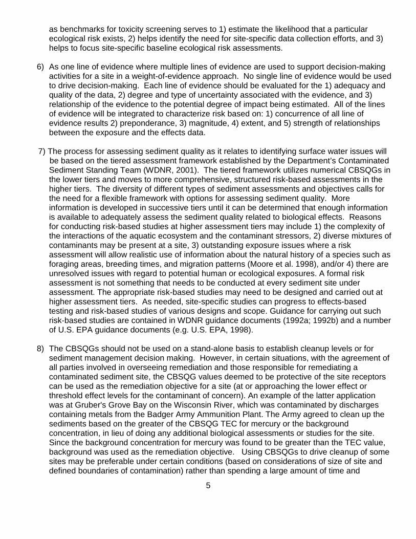
5
as benchmarks for toxicity screening serves to 1) estimate the likelihood that a particularecological risk exists, 2) helps identify the need for site-specific data collection efforts, and 3)helps to focus site-specific baseline ecological risk assessments.
6) As one line of evidence where multiple lines of evidence are used to support decision-makingactivities for a site in a weight-of-evidence approach. No single line of evidence would be usedto drive decision-making. Each line of evidence should be evaluated for the 1) adequacy andquality of the data, 2) degree and type of uncertainty associated with the evidence, and 3)relationship of the evidence to the potential degree of impact being estimated. All of the linesof evidence will be integrated to characterize risk based on: 1) concurrence of all line ofevidence results 2) preponderance, 3) magnitude, 4) extent, and 5) strength of relationshipsbetween the exposure and the effects data.
7) The process for assessing sediment quality as it relates to identifying surface water issues will be based on the tiered assessment framework established by the Department’s Contaminated
Sediment Standing Team (WDNR, 2001). The tiered framework utilizes numerical CBSQGs inthe lower tiers and moves to more comprehensive, structured risk-based assessments in thehigher tiers. The diversity of different types of sediment assessments and objectives calls forthe need for a flexible framework with options for assessing sediment quality. Moreinformation is developed in successive tiers until it can be determined that enough informationis available to adequately assess the sediment quality related to biological effects. Reasonsfor conducting risk-based studies at higher assessment tiers may include 1) the complexity ofthe interactions of the aquatic ecosystem and the contaminant stressors, 2) diverse mixtures ofcontaminants may be present at a site, 3) outstanding exposure issues where a riskassessment will allow realistic use of information about the natural history of a species such asforaging areas, breeding times, and migration patterns (Moore et al. 1998), and/or 4) there areunresolved issues with regard to potential human or ecological exposures. A formal riskassessment is not something that needs to be conducted at every sediment site underassessment. The appropriate risk-based studies may need to be designed and carried out athigher assessment tiers. As needed, site-specific studies can progress to effects-basedtesting and risk-based studies of various designs and scope. Guidance for carrying out suchrisk-based studies are contained in WDNR guidance documents (1992a; 1992b) and a numberof U.S. EPA guidance documents (e.g. U.S. EPA, 1998).
8) The CBSQGs should not be used on a stand-alone basis to establish cleanup levels or forsediment management decision making. However, in certain situations, with the agreement ofall parties involved in overseeing remediation and those responsible for remediating acontaminated sediment site, the CBSQG values deemed to be protective of the site receptorscan be used as the remediation objective for a site (at or approaching the lower effect orthreshold effect levels for the contaminant of concern). An example of the latter applicationwas at Gruber's Grove Bay on the Wisconsin River, which was contaminated by dischargescontaining metals from the Badger Army Ammunition Plant. The Army agreed to clean up thesediments based on the greater of the CBSQG TEC for mercury or the backgroundconcentration, in lieu of doing any additional biological assessments or studies for the site.Since the background concentration for mercury was found to be greater than the TEC value,background was used as the remediation objective. Using CBSQGs to drive cleanup of somesites may be preferable under certain conditions (based on considerations of size of site anddefined boundaries of contamination) rather than spending a large amount of time and

6
resources for additional studies and risk assessments that may lead to considerable costs withlittle benefit. At larger, more complex sites, the costs associated with detailed studies may bewarranted to reduce uncertainties and focus resources on the remedial actions that provide thegreatest benefits (MacDonald et al. 1999).
9) It should be noted that there may be contaminated sediment sites and situations where anumerical chemical concentration related to effects may not be the primary driver in asediment cleanup. Based on a number of balancing factors (e.g., technical feasibility ofremediation methods, considerations of natural attenuation factors specific to the site, remedialimplementability, human health and ecological risks, stakeholder input, and costs)performance-based standards based on the removal of an established mass of contaminant orremoval of visual contamination (applicable to coal tars and petroleum oils) from a site may bethe remediation action objective rather than a numerical concentration. There may besituations where the above balancing factors will also be considered to derive a factoredcleanup concentration that will not initially achieve the science-based protective sedimentconcentration but may after an established time period (e.g., when factors such as naturalattenuation are considered).
5. Considerations and Advantages of Using Consensus-Based Sediment Quality Guidelines
Given the number of guidelines available, selection of any one as the most appropriate and mostreliable for ability to predict toxicity and impacts to benthic species at a study site is difficult. Eachguideline set was generally developed using a different methodology (e.g. Ontario [Persaud et al.1993] used the screening level concentration approach and Ingersoll et al.[1996a] used the effectlevel approach). Each approach for developing guidelines has inherent advantages, limitations,levels of acceptance, different extent of field validation, and differing degree of environmentalapplicability (EPA, 1992). Selecting one set of guidelines is further complicated by uncertaintiesregarding the bioavailability of contaminants in sediments, the effects of co-varying chemicals andchemical mixtures, the ecological relevance of the guidelines, and correlative versus causal relationsbetween chemistry and biological effects (MacDonald et al. 2000a). Given these problems, muchdiscussion has taken place over the use of guidelines as a tool for use in doing sediment qualityassessments (Peddicord et al. 1998). Cautions are often placed on the use of any one set ofguidelines as stand alone decision tools in the assessment and remediation decision making processwithout additional supporting data from toxicity testing and in-field studies. However, recentevaluations based on combining several sets of guidelines into one to yield "consensus-based"guidelines have shown that such guidelines can substantially increase the reliability, predictive ability,and level of confidence in using and applying the guidelines (Crane et al. 2000; MacDonald et al.2000 a, 2000 b; Ingersoll et al. 2000). The agreement of guidelines derived from a variety oftheoretical and empirical approaches helps to establish the validity of the consensus-based values.Use of values from multiple guidelines that are similar for a contaminant provides a weight-of-evidence for relating to actual biological effects.
A series of papers were produced (Swartz, 1999; Macdonald et al. 2000a, 2000b;) that addressedsome of the difficulties associated with the assessment of sediment quality conditions using variousnumerical sediment quality guidelines. The results of these investigations demonstrated thatcombining and integrating the effect levels from several sets of guidelines to result in consensus-based sediment quality guidelines provide a unifying synthesis of the existing guidelines, reflectcausal rather than correlative effects, and can account for the effects of contaminant mixtures in

7
sediment (Swartz, 1999). Additionally, MacDonald et al. (2000a) have evaluated the consensus-based effect levels for reliability in predicting toxicity in sediments by using matching sedimentchemistry and toxicity data from field studies conducted throughout the United States. The results oftheir evaluation showed that most of the consensus-based threshold effect concentrations (TEC -lower effect level) and probable effect concentrations (PEC - upper effect level) for individualcontaminants provide an accurate basis for predicting the absence or presence, respectively, ofsediment toxicity.
Ingersoll et al. (2000, 2001), MacDonald et al. (2000a), and Fairey et al. (2001) evaluated thereliability of using mean quotient concentration-related values to predict the toxicity in sediments of amixture of different contaminants. For example, mean PEC quotients were calculated to evaluate thecombined effects of multiple contaminants in sediments (Ingersoll et al. 2000, 2001; MacDonald et al.2000a). A PEC quotient is calculated for each contaminant in each sample by dividing theconcentration of a contaminant in sediment by the PEC concentration for that chemical. A meanquotient was calculated for each sample by summing the individual quotient for each contaminant andthen dividing this sum by the number of PECs evaluated. Dividing by the number of PEC quotientsnormalizes the value to provide comparable indices of contamination among samples for whichdifferent numbers of contaminants were analyzed. Results of the evaluation showed that the meanPEC quotients that represent mixtures of contaminants were highly correlated to the incidences oftoxicity in the same sediments. See Appendix A for calculation methods and ranges of PEC quotientvalues that are potentially associated with toxicity.
Based on MacDonald et al. (2000a), the consensus-based SQGs can be used for or considered forthe following:• To provide a reliable basis for assessing sediment quality conditions in freshwater ecosystems.
• To identify hot spots with respect to sediment contamination.
• To determine the potential for and spatial extent of injury to sediment-dwelling organisms.
• To evaluate the need for sediment remediation.
• To support the development of monitoring programs to further assess the extent of contaminationand the effects of contaminated sediment on sediment-dwelling organisms.
The above applications are strengthened when the consensus-based values are used in combinationwith other sediment quality assessment tools including effects-based testing (i.e., sediment toxicitytests, bioaccumulation assessments, benthic invertebrate community assessments, and morecomprehensive designed risk-based studies).
The consensus-based SQGs as developed only involve effects to benthic macroinvertebrate species.The guidelines do not consider the potential for bioaccumulation in aquatic organisms andsubsequent food chain transfers to humans or wildlife. Where bioaccumulative compoundsare involved, the consensus-based SQGs need to be used in conjunction with other tools, such asbioaccumulation-based guidelines, bioaccumulation studies, food chain modeling, and tissue residueguidelines to evaluate the direct toxicity and upper food chain effects of these compounds.

8
The MacDonald et al. (2000a) consensus-based sediment quality guidelines have been adopted bythe Minnesota Pollution Control Agency (Crane et al. 2000) for use as sediment quality targets in theSt. Louis River Area of Concern (AOC) on Lake Superior. Following the recommendation in thisguidance for the use of the MacDonald et al. (2000a) consensus-based SQGs, which would involvetheir use on the Wisconsin side of the AOC, would be somewhat consistent with their planned use byMinnesota for making assessment and management decisions for contaminated sediment sites onthe Duluth side of the AOC.
6. Interpreting Sediment Concentrations That Fall Between the Lower TEC and Upper PECConsensus-Based Effect Guideline Concentrations
The greatest certainty in predicting the absence or presence of sediment toxicity occurs at sedimentcontaminant concentrations that are lower than the TEC or greater than the PEC values, respectively.The development of consensus-based SQGs does not include determining the predictability of toxicityrelated to specific contaminant concentrations in the gradient between the TEC and PEC values.Generally, a consensus-based value for a contaminant cannot be set within the range between theTEC and PEC that would have a low frequency of both false negatives and false positives (Swartz,1999). Toxicity does occur at contaminant concentrations between the TEC and PEC values with theamount of toxicity dependent on the particular contaminant and with the incidence of toxicity greaterthan that which occurs at the TEC concentration but less than that which occurs at the PECconcentration (MacDonald et al. 2000a). The TEC and PEC concentrations in the consensus-basedSQGs define three ranges of concentrations for each contaminant (i.e. < TEC ; > TEC but < PEC ;and > PEC. In assessing the degree of concordance that exists between the chemicalconcentrations in the three ranges and the incidence of toxicity, it has been demonstrated that formost reliable consensus-based SQG contaminants, there is a consistent and incremental increase inthe incidence of toxicity to sediment-dwelling organisms with increasing chemical concentrations(MacDonald et al. 2000a, 2000b).
The databases for some individual sets of guidelines, such as the Ontario guidelines (Persaud et al.1993) that have been combined with other guidelines to produce the consensus-based SQGs can beinterpolated to yield predictions of the percent of benthic species that may be affected at specificconcentrations between the lower and upper effect levels. A somewhat conservative but still realisticinterpretation that can be applied to contaminant concentrations that fall in the gradient ofconcentrations between the consensus-based TEC and PEC concentrations is that as theconcentrations of a contaminant increase, toxicity and effects to benthic macroinvertebrate speciesrelated to reductions in survival, reproduction, and growth, bioaccumulation, and benthic communityalterations correspondingly increase and/or are increasingly more probable. An identified limitationof this relationship is that the threshold and nature of this trend can be controlled by factors in specificsediments due to their characteristics (Peddicord et al.1998). Site specific effects-based testing canbe performed to determine the reliability of the prediction of adverse effects based on the use of theCBSQGs on the lower tiers of the assessment.
It is recommended that for the purposes of interpreting the potential impacts of concentrations ofcontaminants between the TEC and PEC values of the CBSQGs or other guidelines, that a midpointeffect concentration (MEC) be derived and qualitative descriptors be applied to the four possibleranges of concentration that will be created. The qualitative descriptors would be termed "ConcernLevels" and would be used as a relative gauge of the potential impacts to the benthic species at thatlevel of contaminant and could be used to prioritize sites for additional studies. A prioritization scheme

9
for ranking sites will, in most cases, depend on professional judgment of staff given the fact thatsampling data for sites will generally be variable for the number of samples and the number ofparameters analyzed for. The descriptive “Concern Level” scheme is shown in the following table forarsenic concentrations and is applied below in Tables 1 – 4 of the CBSQGs for the various groupedcontaminants.
Level ofConcern
ThresholdEffect
Concentration(TEC)
Level ofConcern
MidpointEffect
Concentration(MEC)
Level ofConcern
ProbableEffect
Concentration(PEC)
Level ofConcern
Level 1 Level 2 Level 3 Level 4≤ TEC
CBSQGValue > TEC ≤ MEC
TEC + PEC / 2= MEC > MEC ≤ PEC
CBSQGValue > PEC
Example For CBSQG Values for Arsenic (mg/kg)≤ 9.8 9.8 > 9.8 ≤ 21.4 21.4 > 21.4 ≤ 33 33 > 33
7. Recommended Guidelines and Values to be Used in Sediment Quality Assessments
The consensus-based SQG parameters and related effect concentrations in the tables below are fromMacDonald et al. (2000a) and are indicated in the source column as CBSQGs. Effect-based sediment qualityguideline values for some contaminants from other published sources for which CBSQGs were not availableare also included in the following tables and identified as such in the source column. These values alsorepresent useful tools for assessing sediment quality. However, their ability to predict toxicity and reliabilitymay not be as great as that for the CBSQGs for a number of reasons including incomplete validation from fieldtesting. This uncertainty has to be weighed in using the values in the assessment process. In cases wheremore than one set of guidelines have effect-based concentrations for contaminants for which CBSQGs are notavailable, the effect-based values from that set of guidelines that were the lowest were generally used in theguideline tables that follow. The narrative terminology for effect levels for the latter guidelines may be differentfrom the TEC and PEC terminology from the CBSQGs but the narrative intent is generally the same inestablishing a lower and a higher effect level. Also, the emphasis is on those guidelines developed fromstudies done in freshwater rather than marine or estuarine habitats.
The individual sets of guidelines that were combined and integrated by MacDonald et al. (2000a) to yield theCBSQGs are as follows:
Type of SQG Acronym Approach ReferenceDerivation of Threshold Effect Concentration (TEC) CBSQG by MacDonald et al. (2000a) from the following
Lowest Effect Level LEL Screening Level Concentration Approach Persaud et al. 1993Threshold Effect Level TEL Effect Level Approach Smith et al. 1996.Effect Range - Low ERL Effect Level Approach Long and Morgan, 1991Threshold Effect Level forHyalella azteca in 28-day tests TEL-HA28 Effect Level Approach Ingersoll et al. 1996a and
1996bMinimal Effect Threshold MET Screening Level Concentration Approach EC and MENVIQ, 1992Chronic Equilibrium PartitioningThreshold
SQAL(Sediment Quality
Advisory Level)Equilibrium Partitioning Approach Bolton et al. (1985); Zarba,
(1992); U.S. EPA, 1997
Derivation of Probable Effect Concentration (PEC) CBSQG by MacDonald et al. (2000a) from the followingSevere Effect level SEL Screening Level Concentration Approach Persaud et al. 1993Probable Effect level PEL Effect Level Approach Smith et al. 1996.Effect Range - Median ERM Effect Level Approach Long and Morgan, 1991Probable Effect Level forHyalella azteca in 28-day tests PEL-HA28 Effect Level Approach Ingersoll et al. 1996a and
1996bToxic Effect Threshold TET Effect Level Approach EC and MENVIQ, 1992Acute Equilibrium PartitioningThreshold
No guidelinedeveloped ----- -----

10
8. Additional Considerations For Some Contaminants
PAHs
Some sources of the parent or unsubstituted PAHs that are in Table 2, such as creosote, coal tars,and petroleum oils, can have co-occurring compounds such as substituted PAHs and heterocyclicaromatic compounds (carbozoles, indoles, acridines, and quinolines) that can be equally or moretoxic and more soluble than the listed parent PAH compounds.
Additionally, photoactivation of certain unsubstituted and substituted PAHs, which enhances theirtoxicity to aquatic organisms that have bioaccumulated these compounds, has been demonstratedboth in the laboratory and in the field. The latter may have implications in certain types of habitats(Ankley et al. 2002).
The possible presence of co-occurring toxic compounds where petroleum oils and coal tars areinvolved and photoactivation of PAHs at sites may need to be considered or toxicity may beunderestimated by looking only at the sediment guidelines for the listed parent PAHs in Table 2.
Dioxins and Furans
Polychlorinated dibenzo dioxins (PCDDs) and Polychlorinated dibenzo furans ( PCDFs) are unwantedby products of various chemical manufacturing and combustion processes. They are generallyubiquitous in soils and sediments in urban and rural areas. The potential for greatest levels to befound in environmental media are where chlorinated organic compounds such as certain pesticidesand pentachlorophenol were either manufactured or used. Pentachlorophenol use at wood treatmentoperations (railroad ties, utility poles, or lumber) at some sites in Wisconsin sites has led to dioxin andfuran compound contamination in floodplain soils and stream sediments. Another source of PCDDsand PCDFs is from the production of paper products from chlorine-bleached wood pulp.
There are 210 polychlorinated dibenzo-p-dioxins (PCDDs) and dibenzofurans (PCDFs) which arebased on the points of attachment or substitution of chlorine atoms on the aromatic rings. Of these,17 (7 dioxins and 10 furans) which have chlorine substituted in the 2,3,7,8 positions are thought topose the greatest risks to receptor organisms. In order to account for the differing toxicities of the 172,3,7,8-substituted isomers, each has been given a toxic equivalency factor (TEF) related to the mosttoxic form, 2,3,7,8-TCDD (TEF = 1.0). In terms of risk assessments, those PCDDs and PCDFs notsubstituted in the 2,3,7,8 positions can be ignored. The summed concentration of the TEF of each2,3,7,8-substituted isomer times its concentration equals the toxic equivalent concentration to 2,3,7,8-TCDD or TCDD-EQ concentration. Appendix C provides a table to calculate a summed TCDD-EQconcentration based on the TEF value and reported concentration for each of the 17 2,3,7,8-substituted isomers found in sediments and floodplain soils.
Cyanide
Cyanide as measured and reported as total cyanides in sediments can include hydrogen cyanide(HCN), cyanide ion (CN-), simple cyanides, and metallo- and organo-cyanide complexes. HCN andCN- are grouped as free cyanides and are the most toxic forms of cyanide and the forms of concern.

11
Most complexed cyanides are relatively nontoxic and total cyanide determinations are not very usefulmeasures of either water or sediment quality. Factors that affect the release or dissociation of freecyanides from complexed cyanide forms include pH, redox potential, photodecomposition of thecomplex and release of free cyanide, relative strength of the metallo- and organo-cyanide complexes,and possible presence of bacteria responsible for degradation of ferrocyanide complexes. Insediments, the cyanide in the free form present in the pore water is more relatable to toxicity tobenthic organisms than the total cyanide measured in the solid phase. However, given the abovefactors, it is difficult to predict or model the dissociation and release of the free toxic forms of cyanideto the pore water from the less toxic total cyanide form associated with and normally measured in thesolid phase sediments. A general idea of the concentrations of free cyanide in pore water that wouldbe toxic to benthic invertebrates can be drawn from the acute and chronic toxicity criteria for freecyanides in surface waters classified as supporting Warm Water Sport Fish (NR 105, Wis. Admin.Code) which are 45.8 ug/L and 11.47 ug/L, respectively. Free cyanides as HCN, in general, are notvery persistent in the environment due to their volatility, have low adsorption to sediment particles,high water solubility, and inability to substantially bioaccumulate. Where any significant levels of totalcyanide are detected in sediments, additional analysis may need to be done to also determine whatfractions of the total cyanide are in dissociable forms (amenable to chlorination or weak aciddissociable forms) to give an indication of the potential to release free cyanide with its attendanttoxicity..
9. Background or Reference Site Concentration Considerations In Using the Effect-BasedSQGs
In designing and collecting sediment samples at any phase of a site assessment, consideration mayneed to be given to sampling and analyzing for the same potential chemical stressors, biological data,and/or physical data that are being analyzed for within the study site area at a representativebackground/reference site to be used as benchmarks for comparison purposes. Establishingrepresentative reference sites is critical because if reference sites are not highly similar to the areasunder study, misleading or inappropriate conclusions may be drawn when making data comparisons(Apitz et al. 2002). The background/reference site selected needs to have all the characteristics of thestudy site sediments as close as practical, which includes similar particle size fractions, total organiccarbon content, depositional attributes, and relative positioning (e.g., water depth and stream crosssection) in the water body as the study site location, but needs to be out of the influence of the studysite and the factors responsible for contaminating the study site. Contributions of contaminants (seeAppendix E for a discussion of contamination/contaminant and relation to adverse effects) at thereference site can come from two sources: 1) natural sources based on the soils and geologicalfeatures in the watershed, and 2) anthropogenic sources such as urban runoff. The reference siteshould be relatively unaffected by anthropogenic inputs. In urban areas, sediment sites outside of thefactors that may be influencing the study site may themselves be influenced by ubiquitous urbansources. The sediment quality of reference sites should be reflective of the land uses and land coverof the watershed that the study site is in. Alternatively, suitable background values may be derivedthrough sediment profiles by examining concentrations at depth with the assumption that the lowestconcentration at depth represents the pre-industrial or pre-development sediment horizon (Persaudet al. 1993).
It has to be recognized that in diverse geographical and geological areas, the natural levels of metalsand ubiquitous source anthropogenic organic compounds will vary. Given this variation, dependence
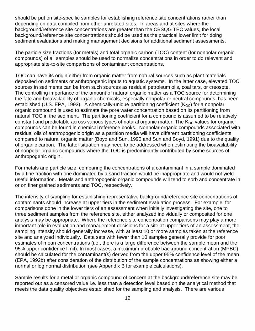
12
should be put on site-specific samples for establishing reference site concentrations rather thandepending on data compiled from other unrelated sites. In areas and at sites where thebackground/reference site concentrations are greater than the CBSQG TEC values, the localbackground/reference site concentrations should be used as the practical lower limit for doingsediment evaluations and making management decisions for additional sediment assessments.
The particle size fractions (for metals) and total organic carbon (TOC) content (for nonpolar organiccompounds) of all samples should be used to normalize concentrations in order to do relevant andappropriate site-to-site comparisons of contaminant concentrations.
TOC can have its origin either from organic matter from natural sources such as plant materialsdeposited on sediments or anthropogenic inputs to aquatic systems. In the latter case, elevated TOCsources in sediments can be from such sources as residual petroleum oils, coal tars, or creosote.The controlling importance of the amount of natural organic matter as a TOC source for determiningthe fate and bioavailability of organic chemicals, especially nonpolar or neutral compounds, has beenestablished (U.S. EPA, 1993). A chemically-unique partitioning coefficient (KOC) for a nonpolarorganic compound is used to estimate the pore water concentration based on its partitioning fromnatural TOC in the sediment. The partitioning coefficient for a compound is assumed to be relativelyconstant and predictable across various types of natural organic matter. The KOC values for organiccompounds can be found in chemical reference books. Nonpolar organic compounds associated withresidual oils of anthropogenic origin as a partition media will have different partitioning coefficientscompared to natural organic matter (Boyd and Sun, 1990 and Sun and Boyd, 1991) due to the qualityof organic carbon. The latter situation may need to be addressed when estimating the bioavailabilityof nonpolar organic compounds where the TOC is predominantly contributed by some sources ofanthropogenic origin.
For metals and particle size, comparing the concentrations of a contaminant in a sample dominatedby a fine fraction with one dominated by a sand fraction would be inappropriate and would not yielduseful information. Metals and anthropogenic organic compounds will tend to sorb and concentrate inor on finer grained sediments and TOC, respectively.
The intensity of sampling for establishing representative background/reference site concentrations ofcontaminants should increase at upper tiers in the sediment evaluation process. For example, forcomparisons done in the lower tiers of an assessment when initially investigating the site, one tothree sediment samples from the reference site, either analyzed individually or composited for oneanalysis may be appropriate. Where the reference site concentration comparisons may play a moreimportant role in evaluation and management decisions for a site at upper tiers of an assessment, thesampling intensity should generally increase, with at least 10 or more samples taken at the referencesite and analyzed individually. Data sets with fewer than 10 samples generally provide for poorestimates of mean concentrations (i.e., there is a large difference between the sample mean and the95% upper confidence limit). In most cases, a maximum probable background concentration (MPBC)should be calculated for the contaminant(s) derived from the upper 95% confidence level of the mean(EPA, 1992b) after consideration of the distribution of the sample concentrations as showing either anormal or log normal distribution (see Appendix B for example calculations).
Sample results for a metal or organic compound of concern at the background/reference site may bereported out as a censored value i.e. less than a detection level based on the analytical method thatmeets the data quality objectives established for the sampling and analysis. There are various

13
methods to handle the censored data to derive values that can be used with the uncensored values inthe data set to derive a mean and standard deviation to be used in the calculation of a maximumprobable background concentration. Analyses of methods to handle censored data show that, inmost cases, sophisticated statistical techniques recommended for estimation problems involvingcensored data are unnecessary or even inappropriate for statistical comparisons where the number ofcensored data samples in a data set are generally small. In general, the simple substitution methodswork best to maintain power and control type I error rate in statistical comparisons (Clarke, 1995).The simple substitution method includes either 1) substitution of the detection limit as the quantifiedconcentration, or 2) substitution of one-half the detection limit as the quantified concentration. Clarke(1995) recommends steps in selecting the substitution method. At its simplest, substitution method 1)above should generally be used where the number of censored data results are less than 40% of thedata set, and method 2) where the censored data is greater than 40%.
9.1 Metals and Silt/Clay Fraction Relationships
There is a strong correlation between decreasing grain size and increasing metal concentrations.Sand-sized material, which is typically low in trace metal concentrations, may serve as a diluent ofmetal-rich finer grained particles. Larger fractions of sand can hide significant trace metalconcentrations and dispersion patterns (Horowitz, 1991). Adjusting for particle grain size effects isimportant for 1) determining natural background levels of trace elements associated with sediments toserve as a baseline for comparison purposes with other sites, 2) for distinguishing and determiningthe degree of anthropogenic enrichment, 3) for comparing metal data from site-to-site on astandardized basis, and 4) providing a means for tracing the extent of metal transport and dispersionby eliminating the diluent effects of large particle size contributions.
Two methods are used to address grain size effects. One is to separate out the sand, silt, and claysized particles from a sample by sieving and analyzing the separate fractions. The other method is toassume that the majority of the metals in a sample are associated with the fine fraction (silt + clay)and then mathematically normalize the metal data to this fraction by dividing the bulk concentration bythe fine fraction percentage expressed as a decimal fraction to yield mg of a metal / kg of fines.Particle size analysis of a sediment sample is usually reported as percent sand, silt, and clayfractions. An example of normalizing a bulk sediment concentration for a metal to the fine fraction fora sample with 84 mg/kg of lead and 60% fines (40% silt + 20% clay) is 84 mg Pb/kg ÷ 0.60 kgfines /kg sediment = 140 mg lead / kg of fines. The assumption may not always hold true that all ormost of the metals are associated with the fine fraction. Also, when the fine fraction falls below 50%of the total combined fractions, the mathematical normalization may not represent the true metalconcentration in the fines (Horowitz, 1991). The normalization to the fine fractions should at aminimum be done at least qualitatively to compare on a relative basis the fine fraction contentsbetween the sediment samples where the metal concentrations are being compared. Besides grainsize, other normalizing factors have been used and include iron, aluminum, and total organic carbon(Daskalakis et al. 1995).
It should be noted that for the CBSQGs for the metals, MacDonald et al. (2000a) do not indicate whatthe relative percentage of the mineral particle size fractions (% sand, silt, and clay) were assumed tobe associated with the expressed values. TOC may play some role in the chemical form of the metaland thus its release from the sediments and its bioavailability. TOC may serve as a secondarybinding phase of metals with acid volatile sulfates (AVS) serving as the primary binding phase. It isdifficult to predict or measure the role of TOC as it relates to metals. For this reason, the study site

14
bulk sediment metal concentrations need to be directly compared with the CBSQG concentrations inTable 1 without any adjustments for TOC or fine fraction content. The process above for adjustingmetal concentrations based on the percent fines is an additional assessment tool for comparing theconcentrations between the unimpacted reference site and the study site and between study sites ona fine content-normalized basis and does not play a role in SQG application.
Normalizing contaminant concentrations to the mineral fine content or TOC content is not to be donefor assessing toxicity under TSCA or determining hazardous waste characteristics under the ToxicityCharacteristic Leaching Procedure (TCLP) test. The sample dry weight bulk concentrations asreported by the analytical laboratory are to be used for comparison with the applicable criteria underthese regulations.
9.2 Nonpolar Organic Compound and Total Organic Carbon Relationships
In the case of nonpolar organic compounds such as PAHs, PCBs, dioxins/furans, and chlorinatedpesticides, the bulk sediment concentrations can be normalized to the TOC content for site-to-sitecomparison purposes by dividing the dry weight sediment concentration by the percent TOC in thesediment expressed as a decimal fraction. For example the TOC normalized PCB concentration for asediment concentration of 7 mg/kg with 3.5% TOC is 200 mg PCB / kg TOC (i.e., 7 mg PCBs/kg ÷0.035 kg TOC/kg = 200 mg PCB/kg TOC). Normalization of nonpolar organic compounds to TOCcontent is valid only if the TOC content in the sediments is greater than 0.2%. At TOC concentrationsless than 0.2%, other factors that influence partitioning to the sediment pore waters (e.g., particle sizeand sorption to nonorganic mineral fractions) become relatively more important (Di Toro et al.1991).
MacDonald et al. (2000a) indicate that some individual sets of guidelines that were used in theirconsensus-based approach were originally expressed on an organic carbon-normalized basis. Theyconverted the values in these sets of to dry weight-normalized values at 1% organic carbon to beaveraged with the other sets of guideline values to yield the CBSQGs. The final MacDonald et al.(2000a) CBSQG values are expressed on a dry weight basis without regard to organic carboncontent. It should be noted that the consensus-based SQG values in Tables 2, 3, and 4 below areexpressed on an assumed dry weight normalized basis at 1% organic carbon. It has beenestablished that the organic carbon content of sediment is an important factor influencing themovement and bioavailability of nonpolar organic compounds (e.g., PAHs, PCBs, and chlorinatedpesticides) between the organic carbon content in bulk sediments and the sediment pore water andoverlying surface water. Biological responses of benthic organisms to nonionic organic chemical insediments are different across sediments when the sediment concentrations are expressed on a dryweight basis, but similar when expressed on an organic carbon normalized basis (ug chemical / gorganic carbon basis) (U.S. EPA, 2000).
To appropriately compare the CBSQG dry weight-normalized to 1% TOC values with the dry weightconcentrations in the study sediments of variable TOC content, the study sediment contaminantconcentrations also need to be converted to a dry weight-normalized to 1% TOC basis.Appendix D provides a spread sheet for calculating dry weight sediment concentrations for nonpolarorganic compounds normalized to 1% TOC. The concentrations given are for an example sediment.Appendix D also contains a spreadsheet for calculating the concentrations of metals normalized tothe fine fraction in a sediment sample. An Excel spreadsheet is available for doing the calculations.

15
An example showing the necessity of doing this conversion to a common 1% TOC basis for organiccompounds is shown as follows:
• The threshold effect concentration (TEC) for total PAHs (TPAHs) is 1,610 ug/kg at 1% TOC.• The example site under assessment has a TPAH concentration of 7,300 ug/kg at 5% TOC.• Comparing the dry weight concentrations between the guideline value and the example site
concentration without consideration of the TOC content differences would appear to show thatthe study site concentrations are greater than the TEC guideline value (7,300 study site vs.1,610 TEC).
• To convert the study site TPAH concentration to a dry weight concentration normalized to 1%,divide the 7,300 ug/kg value by 5 (5% TOC content) = 1,460 ug TPAH/kg at 1% TOC. On thecommon basis of 1% TOC, the study site TPAH concentration is less than the TECconcentration (1,460 ug/kg study site vs. 1,610 ug/kg TEC).
• In the case above, another approach for converting the concentrations to a commonnormalized basis is to multiply the TEC concentration by 5 that is the percent TOC of the studysite sample. The common basis here are dry weight-normalized concentrations at 5% TOC(7,300 ug/kg study site vs. 8,050 ug/kg TEC).
10. Point of Application of the CBSQGs in the Bed Sediment
The numerical CBSQGs apply to the biologically active zone associated with deposited sediments inflowing (streams and rivers) and static (lakes and ponds) water bodies and wetland soils andsediments. The biologically active zone is inhabited by infaunal organisms including microbes,meiofauna, and macroinvertebrates and other organisms (e.g., egg and larval stage of fish) thatspend all or part of their life cycles associated either within (infaunal) or on (epibenthic) the bottomsediments. The community of organisms present will generally depend on the physical and chemicalcharacteristics of the waterbody and bottom sediments as determined by the watershed location andecoregion within the State. The depth of the biologically-active zone varies between sites dependingon the substrate characteristics present (including particle size fractions, organic matter content,compaction, pore-water geochemistry, and water content) which influence the composition ofsediment-associated organisms present. The biologically active zone typically encompasses the top20 to 40 cm. of sediment in freshwater environments (Clarke et al. 2001). The majority of benthicorganisms will usually be associated with the upper strata (e.g., 15 cm) related to these depth ranges.Certain invertebrate and/or amphibian species can utilize habitats deeper in bed sediments during aportion of their life history (e.g., down to 100 cm below the sediment surface) (MacDonald et al.2000a). The best available knowledge about the local composition of sediment-associated biota andthe bioactive depth zone they occupy should supplement the generic depth assumptions above(Clarke et al. 2001) where possible. Contaminants in sediments at depths below the biologicallyactive zone can be of concern because of their potential to move to the upper sediment strata throughvarious mechanisms that include diffusion and being transported on groundwater flows that dischargeto the surface water body. The groundwater-sediment-surface water zone is a zone of transitions inwhich various environmental factors can affect contaminant fate and transport.
The CBSQGs should be considered when assessing contaminated soils and sediments deposited onupper bank areas and floodplain areas that have the potential to be eroded or scoured andtransported to and deposited in a nearby surface water body.

16
11. Other Approaches Being Used to Develop SQGs
U.S. EPA has developed national equilibrium partitioning sediment guidelines (ESGs) for a broadrange of sediment types. They have finalized the methodologies for deriving ESGs for nonionicorganic chemicals (2000a) and mixtures of certain metals (cadmium, copper, lead, nickel, zinc, andsilver (U.S.EPA, 2000b). U.S. EPA is planning to publish final guidance (EPA, 2000c) for developingSQGs based on a combination of the equilibrium partitioning (EqP) approach, quantitative structureactivity relationships, narcosis theory, and concentration addition models for mixtures of PAH found atspecific sites. The EqP-based summed PAH toxicity model provides a method to address causality,account for bioavaliability, consider mixtures, and predict toxicity and ecological effects (U.S. EPA,2000). The U.S. EPA guidance indicates that the total number of PAHs that need to be considered inSQG development is 34 (18 parent and 16 with alkylated groups). Use of fewer than 34 may greatlyunderestimate the total toxicological contribution of PAH mixtures. The guidance requires the use ofconservative uncertainty factors to be applied when fewer than the 34 are being used to estimate site-specific toxicity of PAH mixtures.
When guidance has been published in final for the use and application of the ESGs for metals, PAHmixtures, and other nonionic organic compounds, the Water Quality Standards section plans toproduce additional guidance on the use of the ESGs to be used in addition to or instead of theCBSQGs. U.S. EPA’s apparent intent is not to use the ESG numeric values as stand alone criteriafor application as part of a States water quality standards under Section 3 (c) of the Clean Water Act,but to use them as a screening tool in conjunction with other assessment tools such as toxicity testingin evaluating and prioritizing sites under various programs (e.g., developing Total Maximum DailyLoads (TMDLs) s and WPDES permit limitations, Superfund, RCRA).

17
Table 1. Recommended Sediment Quality Guideline Values For Metals and Associated Levels ofConcern To Be Used In Doing Assessments of Sediment Quality.
mg/kg dry wt.++
Metal
Level 1Concern
≤ TECTEC
Level 2Concern
> TEC≤ MEC
MEC
Level 3Concern
> MEC≤ PEC
PEC
Level 4Concern
> PEC
Source of SQGEffect-Based
Concentrations
Antimony ⇦⇦⇦⇦ 2 ⇔⇔⇔⇔ 13.5 ⇔⇔⇔⇔ 25 ⇨⇨⇨⇨ NOAA (1991) 1.
Arsenic ⇦⇦⇦⇦ 9.8 ⇔⇔⇔⇔ 21.4 ⇔⇔⇔⇔ 33 ⇨⇨⇨⇨ CBSQG (2000a)2
Cadmium ⇦⇦⇦⇦ 0.99 ⇔⇔⇔⇔ 3.0 ⇔⇔⇔⇔ 5.0 ⇨⇨⇨⇨ CBSQG (2000a)Chromium ⇦⇦⇦⇦ 43 ⇔⇔⇔⇔ 76.5 ⇔⇔⇔⇔ 110 ⇨⇨⇨⇨ CBSQG (2000a)Copper ⇦⇦⇦⇦ 32 ⇔⇔⇔⇔ 91 ⇔⇔⇔⇔ 150 ⇨⇨⇨⇨ CBSQG (2000a)Iron ⇦⇦⇦⇦ 20,000 ⇔⇔⇔⇔ 30,000 ⇔⇔⇔⇔ 40,000 ⇨⇨⇨⇨ Ontario (1993) 3
Lead ⇦⇦⇦⇦ 36 ⇔⇔⇔⇔ 83 ⇔⇔⇔⇔ 130 ⇨⇨⇨⇨ CBSQG (2000a)Manganese ⇦⇦⇦⇦ 460 ⇔⇔⇔⇔ 780 ⇔⇔⇔⇔ 1,100 ⇨⇨⇨⇨ Ontario (1993)Mercury ⇦⇦⇦⇦ 0.18 ⇔⇔⇔⇔ 0.64 ⇔⇔⇔⇔ 1.1 ⇨⇨⇨⇨ CBSQG (2000a)Nickel ⇦⇦⇦⇦ 23 ⇔⇔⇔⇔ 36 ⇔⇔⇔⇔ 49 ⇨⇨⇨⇨ CBSQG (2000a)Silver ⇦⇦⇦⇦ 1.6 ⇔⇔⇔⇔ 1.9 ⇔⇔⇔⇔ 2.2 ⇨⇨⇨⇨ BC (1999) 4.
Zinc ⇦⇦⇦⇦ 120 ⇔⇔⇔⇔ 290 ⇔⇔⇔⇔ 460 ⇨⇨⇨⇨ CBSQG (2000a) ++ The CBSQGs for organic compounds are expressed on a dry weight concentration at 1% TOC in sediments. However, unlike the organic compounds, the CBSQG and study site metals concentrations can be compared on a bulk chemistry basis and do not need to be adjusted to a 1% TOC basis to do the comparison. TOC does not play the same role in determining metals availability as it does in determining organic compound availability.
1. NOAA (1991) = Long, E.R. and L.G. Morgan. 1991. The potential for biological effects of sediment-sorbed contaminants tested in the National Status and Trends Program. NOAA Technical Memorandum NOS OMA 52. National Oceanic and Atmospheric Administration. Seattle, Washington.
2. CBSQG (2000a) = MacDonald, D.D., C.G. Ingersoll, and T.A. Berger. 2000a. Development and evaluation of consensus-based sediment quality guidelines for freshwater ecosystems. Arch. Environ. Contam. Toxicol. 39:20-31.
3. Ontario (1993) = Persaud, D.R., R. Jaagumagi, and A. Hayton. 1993. Guidelines for the protection and management of aquatic sediments in Ontario. Standards Development Branch. Ontario Ministry of Environment and Energy. Toronto, Canada.
4. MacDonald, D.D. and M. MacFarlane. 1999. (Draft). Criteria for managing contaminated sediment in British Columbia. British Columbia Ministry of Environment, Lands, and Parks. Victoria, British Columbia.

18
Table 2. Recommended Sediment Quality Guideline Values For Polycyclic Aromatic Hydrocarbons(PAHs) and Associated Levels of Concern To Be Used In Doing Assessments of Sediment Quality.
ug/kg dry wt. at 1% TOC ++
PAHLevel 1Concern
≤ TECTEC
Level 2Concern
> TEC≤ MEC
MEC
Level 3Concern
> MEC≤ PEC
PEC
Level 4Concern
> PEC
Source of SQGEffect-Based
Concentrations
Low Molecular Weight PAHs ( 3 or less benzene rings)Acenapthene ⇦⇦⇦⇦ 6.7 ⇔⇔⇔⇔ 48 ⇔⇔⇔⇔ 89 ⇨⇨⇨⇨ CCME (1999) 1.
Acenaphthylene ⇦⇦⇦⇦ 5.9 ⇔⇔⇔⇔ 67 ⇔⇔⇔⇔ 128 ⇨⇨⇨⇨ CCME (1999)Anthracene ⇦⇦⇦⇦ 57.2 ⇔⇔⇔⇔ 451 ⇔⇔⇔⇔ 845 ⇨⇨⇨⇨ CBSQG (2000a) 2.
Fluorene ⇦⇦⇦⇦ 77.4 ⇔⇔⇔⇔ 307 ⇔⇔⇔⇔ 536 ⇨⇨⇨⇨ CBSQG (2000a)Naphthalene ⇦⇦⇦⇦ 176 ⇔⇔⇔⇔ 369 ⇔⇔⇔⇔ 561 ⇨⇨⇨⇨ CBSQG (2000a)2-methylnapthalene ⇦⇦⇦⇦ 20.2 ⇔⇔⇔⇔ 111 ⇔⇔⇔⇔ 201 ⇨⇨⇨⇨ CCME (1999)Phenanthrene ⇦⇦⇦⇦ 204 ⇔⇔⇔⇔ 687 ⇔⇔⇔⇔ 1,170 ⇨⇨⇨⇨ CBSQG (2000a)
High Molecular Weight PAHs ( 4 or more benzene rings)Benz(a)anthracene ⇦⇦⇦⇦ 108 ⇔⇔⇔⇔ 579 ⇔⇔⇔⇔ 1,050 ⇨⇨⇨⇨ CBSQG (2000a)Benzo(a)pyrene ⇦⇦⇦⇦ 150 ⇔⇔⇔⇔ 800 ⇔⇔⇔⇔ 1,450 ⇨⇨⇨⇨ CBSQG (2000a)Benzo(e)pyrene ⇦⇦⇦⇦ 150 ⇔⇔⇔⇔ 800 ⇔⇔⇔⇔ 1,450 ⇨⇨⇨⇨ Similar as above 3.
Benzo(b)fluoranthene ⇦⇦⇦⇦ 240 ⇔⇔⇔⇔ 6,820 ⇔⇔⇔⇔ 13,400 ⇨⇨⇨⇨ Similar as below 4.
Benzo(k)fluoranthene ⇦⇦⇦⇦ 240 ⇔⇔⇔⇔ 6,820 ⇔⇔⇔⇔ 13,400 ⇨⇨⇨⇨ Persaud et al. 1993 5
Benzo(g,h,I)perylene ⇦⇦⇦⇦ 170 ⇔⇔⇔⇔ 1,685 ⇔⇔⇔⇔ 3,200 ⇨⇨⇨⇨ Persaud et al. 1993Chrysene ⇦⇦⇦⇦ 166 ⇔⇔⇔⇔ 728 ⇔⇔⇔⇔ 1,290 ⇨⇨⇨⇨ CBSQG (2000a)Dibenz(a,h)anthracene ⇦⇦⇦⇦ 33 ⇔⇔⇔⇔ 84 ⇔⇔⇔⇔ 135 ⇨⇨⇨⇨ CBSQG (2000a)Fluoranthene ⇦⇦⇦⇦ 423 ⇔⇔⇔⇔ 1,327 ⇔⇔⇔⇔ 2,230 ⇨⇨⇨⇨ CBSQG (2000a)Indeno(1,2,3-cd)pyrene ⇦⇦⇦⇦ 200 ⇔⇔⇔⇔ 1,700 ⇔⇔⇔⇔ 3,200 ⇨⇨⇨⇨ CBSQG (2000a)Pyrene ⇦⇦⇦⇦ 195 ⇔⇔⇔⇔ 858 ⇔⇔⇔⇔ 1,520 ⇨⇨⇨⇨ CBSQG (2000a)
Total PAHsTotal PAHs ⇦⇦⇦⇦ 1,610 ⇔⇔⇔⇔ 12,205 ⇔⇔⇔⇔ 22,800 ⇨⇨⇨⇨ CBSQG (2000a) ++ To compare the study site concentrations with the Table 2 concentrations on a common basis, divide the study site concentrations by the %TOC at the study site to yield a dry wt. normalized value at 1% TOC. If no site TOC information is available, assume a 1% TOC content.
1. CCME (1999) = Canadian Council of Ministers of the Environment (CCME). 1999. Canadian sediment quality guidelines for the protection of aquatic life: Summary tables. In: Canadian environmental quality guidelines. 1999. Canadian Council of Ministers of the Environment, Winnipeg.2. CBSQG (2000a) = MacDonald, D.D., C.G. Ingersoll, and T.A. Berger. 2000a. Development and evaluation of consensus-based sediment quality guidelines for freshwater ecosystems. Arch. Environ. Contam. Toxicol. 39:20-31.3. There are no guideline values for Benzo(e)pyrene. "Similar as above" assumes the similarity of the chemical structure of Benzo(e)pyrene with Benzo(a)pyrene would yield similar quantitative structure activity relationships (QSARs) as it relates to toxicity, therefore the effect level concentrations that were derived for Benzo(a)pyrene would also apply to Benzo(e)pyrene.4. There are no guideline values for Benzo(b)fluoranthene. "Similar as below" assumes the similarity of the chemical structure of Benzo(b)fluoranthene with Benzo(k)fluoranthene would yield similar quantitative structure activity relationships (QSARs) as it Relates to toxicity, therefore the effect level concentrations that were derived for Benzo(k)fluoranthene would also apply to Benzo(b)fluoranthene.5. Ontario (1993) = Persaud, D.R., R. Jaagumagi, and A. Hayton. 1993. Guidelines for the protection and management of aquatic sediments in Ontario. Standards Development Branch. Ontario Ministry of Environment and Energy. Toronto, Canada.

19
Table 3. Recommended Sediment Quality Guideline Values For Polychlorinated Biphenyls (PCBs)And Chlorinated and Other Pesticides and Associated Levels of Concern To Be Used In DoingAssessments of Sediment Quality.
ug/kg dry wt. at 1% TOC ++
PCB and Pesticides
Level 1Concern
≤ TECTEC
Level 2Concern
> TEC≤ MEC
MEC
Level 3Concern
> MEC≤ PEC
PEC
Level 4Concern
> PEC
Source of SQGEffect-Based
Concentrations
PCBsTotal PCBs ⇦⇦⇦⇦ 60 ⇔⇔⇔⇔ 368 ⇔⇔⇔⇔ 676 ⇨⇨⇨⇨ CBSQG (2000a) 1.
PesticidesAldrin ⇦⇦⇦⇦ 2 ⇔⇔⇔⇔ 41 ⇔⇔⇔⇔ 80 ⇨⇨⇨⇨ Ontario (1993) 2.
BHC ⇦⇦⇦⇦ 3 ⇔⇔⇔⇔ 62 ⇔⇔⇔⇔ 120 ⇨⇨⇨⇨ Ontario (1993)alpha-BHCalpha-BHCalpha-BHCalpha-BHC ⇦⇦⇦⇦ 6 ⇔⇔⇔⇔ 53 ⇔⇔⇔⇔ 100 ⇨⇨⇨⇨ Ontario (1993)beta-BHCbeta-BHCbeta-BHCbeta-BHC ⇦⇦⇦⇦ 5 ⇔⇔⇔⇔ 108 ⇔⇔⇔⇔ 210 ⇨⇨⇨⇨ Ontario (1993)gamma-BHCgamma-BHCgamma-BHCgamma-BHC(lindane)(lindane)(lindane)(lindane) ⇦⇦⇦⇦ 3 ⇔⇔⇔⇔ 4 ⇔⇔⇔⇔ 5 ⇨⇨⇨⇨ CBSQG (2000a)Chlordane ⇦⇦⇦⇦ 3.2 ⇔⇔⇔⇔ 10.6 ⇔⇔⇔⇔ 18 ⇨⇨⇨⇨ CBSQG (2000a)Dieldrin ⇦⇦⇦⇦ 1.9 ⇔⇔⇔⇔ 32 ⇔⇔⇔⇔ 62 ⇨⇨⇨⇨ CBSQG (2000a)Sum DDD ⇦⇦⇦⇦ 4.9 ⇔⇔⇔⇔ 16.5 ⇔⇔⇔⇔ 28 ⇨⇨⇨⇨ CBSQG (2000a)Sum DDE ⇦⇦⇦⇦ 3.2 ⇔⇔⇔⇔ 17 ⇔⇔⇔⇔ 31 ⇨⇨⇨⇨ CBSQG (2000a)Sum o,p’ + p,p’DDT
⇦⇦⇦⇦ 4.2 ⇔⇔⇔⇔ 33.6 ⇔⇔⇔⇔ 63 ⇨⇨⇨⇨ CBSQG (2000a)
Sum of DDT +DDD+ DDE
⇦⇦⇦⇦ 5.3 ⇔⇔⇔⇔ 289 ⇔⇔⇔⇔ 572 ⇨⇨⇨⇨ CBSQG (2000a)
Endrin ⇦⇦⇦⇦ 2.2 ⇔⇔⇔⇔ 104.6 ⇔⇔⇔⇔ 207 ⇨⇨⇨⇨ CBSQG (2000a)Heptachlor Epoxide ⇦⇦⇦⇦ 2.5 ⇔⇔⇔⇔ 9.3 ⇔⇔⇔⇔ 16 ⇨⇨⇨⇨ CBSQG (2000a)Mirex ⇦⇦⇦⇦ 7 ⇔⇔⇔⇔ 10.5 ⇔⇔⇔⇔ 14 ⇨⇨⇨⇨ BC (1999) 3.
Toxaphene ⇦⇦⇦⇦ 1 ⇔⇔⇔⇔ 1.5 ⇔⇔⇔⇔ 2 ⇨⇨⇨⇨ BC (1999)++ To compare the study site concentrations with the Table 3 concentrations on a common basis, divide the study site concentrations by the %TOC at the study site to yield a dry wt. - normalized value at 1% TOC. If no site TOC information is available, assume a 1% TOC content.
1. CBSQG (2000a) = MacDonald, D.D., C.G. Ingersoll, and T.A. Berger. 2000a. Development and evaluation of consensus-based sediment quality guidelines for freshwater ecosystems. Arch. Environ. Contam. Toxicol. 39:20-31.
2. Ontario (1993) = Persaud, D.R., R. Jaagumagi, and A. Hayton. 1993. Guidelines for the protection and management of aquatic sediments in Ontario. Standards Development Branch. Ontario Ministry of Environment and Energy. Toronto, Canada.
3. MacDonald, D.D. and M. MacFarlane. 1999. (Draft). Criteria for managing contaminated sediment in British Columbia. BritishColumbia Ministry of Environment, Lands, and Parks. Victoria, British Columbia.

20
Table 4. Recommended Sediment Quality Guideline Values For Assorted Contaminants andAssociated Levels of Concern To Be Used In Doing Assessments of Sediment Quality.
ug/kg dry wt. at 1% TOC ++
Sediment Contaminant
Level 1Concern
≤ TECTEC
Level 2Concern
> TEC≤ MEC
MEC
Level 3Concern
> MEC≤ PEC
PEC
Level 4Concern
> PEC
Source of SQGEffect-Based
Concentrations
Benzene ⇦⇦⇦⇦ 57 ⇔⇔⇔⇔ 83.5 ⇔⇔⇔⇔ 110 ⇨⇨⇨⇨ BC (1999) 1.
Toluene ⇦⇦⇦⇦ 890 ⇔⇔⇔⇔ 1,345 ⇔⇔⇔⇔ 1,800 ⇨⇨⇨⇨ BC (1999)Xylene ⇦⇦⇦⇦ 25 ⇔⇔⇔⇔ 37.5 ⇔⇔⇔⇔ 50 ⇨⇨⇨⇨ BC (1999)2,3,7,8-TCDD (pgTEQ/g) ⇦⇦⇦⇦ 0.85 ⇔⇔⇔⇔ 11.2 ⇔⇔⇔⇔ 21.5 ⇨⇨⇨⇨ Canada (2002) 2.
Pentachlorophenol ⇦⇦⇦⇦ 150 ⇔⇔⇔⇔ 175 ⇔⇔⇔⇔ 200 ⇨⇨⇨⇨ Janisch (1990) 3.
Tributyltin ⇦⇦⇦⇦ 0.52 ⇔⇔⇔⇔ 1.73 ⇔⇔⇔⇔ 2.94 ⇨⇨⇨⇨ Janisch (1994) 4.
1,2-Dichlorobenzene ⇦⇦⇦⇦ 23 ⇔⇔⇔⇔ ----- ⇔⇔⇔⇔ 23 ⇨⇨⇨⇨ Washington (1991) 5.
1,4-Dichlorebenzene ⇦⇦⇦⇦ 31 ⇔⇔⇔⇔ 60.5 ⇔⇔⇔⇔ 90 ⇨⇨⇨⇨ Washington (1991)1,2,4-Trichlorobenzene ⇦⇦⇦⇦ 8 ⇔⇔⇔⇔ 13 ⇔⇔⇔⇔ 18 ⇨⇨⇨⇨ Washington (1991)Dimethyl Phthalate ⇦⇦⇦⇦ 530 ⇔⇔⇔⇔ ----- ⇔⇔⇔⇔ 530 ⇨⇨⇨⇨ Washington (1991)Diethyl Phthalate ⇦⇦⇦⇦ 610 ⇔⇔⇔⇔ 855 ⇔⇔⇔⇔ 1,100 ⇨⇨⇨⇨ Washington (1991)Di-N-Butyl Phthalate ⇦⇦⇦⇦ 2,200 ⇔⇔⇔⇔ 9,600 ⇔⇔⇔⇔ 17,000 ⇨⇨⇨⇨ Washington (1991)Di-N-Octyl Phthalate ⇦⇦⇦⇦ 580 ⇔⇔⇔⇔ 22,790 ⇔⇔⇔⇔ 45,000 ⇨⇨⇨⇨ Washington (1991)Dibenzofuran ⇦⇦⇦⇦ 150 ⇔⇔⇔⇔ 365 ⇔⇔⇔⇔ 580 ⇨⇨⇨⇨ Washington (1991)Phenol ⇦⇦⇦⇦ 4,200 ⇔⇔⇔⇔ 8,100 ⇔⇔⇔⇔ 12,000 ⇨⇨⇨⇨ Washington (1991)2-Methylphenol ⇦⇦⇦⇦ 6,700 ⇔⇔⇔⇔ ----- ⇔⇔⇔⇔ 6,700 ⇨⇨⇨⇨ Washington (1991)2,4-Dimethyl Phenol ⇦⇦⇦⇦ 290 ⇔⇔⇔⇔ ----- ⇔⇔⇔⇔ 290 ⇨⇨⇨⇨ Washington (1991)Benzyl Alcohol ⇦⇦⇦⇦ 570 ⇔⇔⇔⇔ 650 ⇔⇔⇔⇔ 730 ⇨⇨⇨⇨ Washington (1991)Benzoic Acid ⇦⇦⇦⇦ 6,500 ⇔⇔⇔⇔ ----- ⇔⇔⇔⇔ 6,500 ⇨⇨⇨⇨ Washington (1991)++ To compare the study site concentrations with the Table 4 concentrations on a common basis, divide the study site concentrations by the %TOC at the study site to yield a dry wt. - normalized value at 1% TOC. If no site TOC informatio is available, assume a 1% TOC content.
1. MacDonald, D.D. and M. MacFarlane. 1999. (Draft). Criteria for managing contaminated sediment in British Columbia. BritishColumbia Ministry of Environment, Lands, and Parks. Victoria, British Columbia.
2. Canadian Sediment Quality Guidelines for the Protection of Aquatic Life. Summary Table. Update 2002. Canadian Council of Ministers of the Environment.3. Janisch (1990) = Memo of February 7, 1990 prepared to Maltbey of NCD entitled Sediment Quality Criteria for Pentachlorophenol related to the Semling-Menke Company Contaminated Groundwater Inflow to the Wisconsin River. Sediment guidelines for Developed for pentachlorophenol in sediment based on the water quality criteria in NR 105. Considerations made for pH of of water and organic carbon partitioning coefficient of pentachlorophenol. The pH determines the dissociated / undissociated forms of pentachlorophenol and its partitioning coefficient. The pH used to calculate the above sediment values was 7.0. The Koc value used was 3.226 or 1,821 L/kg OC. The organic carbon content of the sediment was assumed to be 1%. The TEC and PEC values above for PCP were based on the chronic and acute water quality criteria in NR 105, respectively.4. Janisch (1994) = Memo of November 14, 1994 prepared to LaValley of NWD entitled Preliminary Ecological Risk Assessment for the Contaminated Sediments Associated with the Fraser Shipyard Site, Superior, Wisconsin. Sediment guidelines for tributyltin derived based on the proposed water quality criteria for tributyltin at the time (EPA, 1988). The organic carbon partitioning coefficient used was 1,970 L/kg OC and an assumed organic carbon content of 1% in sediment. The TEC and PEC values above for tributyltin were based on the chronic and acute water quality values as proposed by EPA, respectively.5. Washington (1991) = Sediment Management Standards, Chapter 173-204 WAC, Washington State Department of Ecology. April 1991. The Standards were developed using the Apparent Effects Threshold Approach. The TEC and PEC values above for the compounds are based on no effect and minimal effect standards, respectively, from the Washington Standards and are intended to apply to Puget Sound, an estuarine habitat. The values were calculated based on an assumed TOC content in sediment of 1%.

21
References
Ankley, G.T., L.P. Burkhard, P.M. Cook, S.A. Diamond, R.J. Erickson, and D.R. Mount. 2002.Assessing risks from photoactivated toxicity of polycyclic aromatic hydrocarbons to aquaticorganisms. Mid-Continent Ecology Division. National Health and Environmental Effects ResearchLaboratory. U.S. EPA. Duluth, MN.
Apitz, S.E. et al. 2000. Critical issues for contaminated sediment management. Marine EnvironmentalSupport Office. U.S. Navy. Chapter 7. Evaluating reference area conditions in sediment assessments.MESO-02-TM-01.
Bolton, S.H., Breteler, R.J., B.W. Vigon, J.A. Scanlon, and S.L. Clark. 1985. National perspective onsediment quality. Prepared for U.S. EPA, Washington, DC. 194 pgs.
Boyd, S.A. and S. Sun. 1990. Residual petroleum and polychlobiphenyl oils as sorptive phases fororganic contaminants in soils. Environ. Sci. Technol. 24:142-144.
British Columbia. Ministry of Environment, Lands and Parks. 1999. Criteria for managingcontaminated sediment in British Columbia (Draft). Prepared pursuant to Section 26(1) of the WasteManagement Act.
Canadian Council of Ministers of the Environment (CCME). 1999. Canadian sediment qualityguidelines for the protection of aquatic life: Summary tables. In: Canadian environmental qualityguidelines. 1999. Canadian Council of Ministers of the Environment, Winnipeg.
Chapman, P.M., M. Cano, A.T. Fritz, C. Gaudet, C.A. Menzie, M. Sprenger, and W.A. Stubblefield.1997. Critical issues in methodological uncertainty. Session 4. Contaminated site cleanup decisions.Chapter 7. Workgroup summary report on contaminated site cleanup decisions. Proceedings of thePellston Workgroup on Sediment Ecological Risk Assessment. April 23-28, 1995. Pacific Grove, CA.Edited by C.G. Ingersoll, T. Dillon, and G.R Biddinger. Society of Environmental Toxicology andChemistry. (SETAC Press).
Clarke, D.G., Palermo, M.R., and T.C. Sturgis. 2001. Subaqueous cap design: Selection ofbioturbation profiles, depths, and rates. DOER Technical Notes Collection. ERDC TN-DOER-C21.U.S. Army Engineers Research and Development Center, Vicksburg, MS.
Clarke, J.U. 1995. Guidelines for statistical treatment of less than detection limit data in dredgedsediment evaluations. U.S. Army Engineer Waterways Experiment Station. Vicksburg, MS. EEDP-04-23.
Crane, J.L., D.D. MacDonald, C.G. Ingersoll, D.E. Smorong, R.A. Lindskoog, C.G. Severn, T.A.Berger, and L.J. Field. 2000. Development of a framework for evaluating numerical sediment qualitytargets and sediment contamination in the St. Louis River Area of Concern. U.S. EnvironmentalProtection Agency, Great Lakes National Program Office, Chicago, IL. EPA-905-R-00-008.
Daskalakis, K.D. and T.P. O'Connor. 1995. Normalization and elemental sediment contamination inthe coastal United States. Environ. Sci. Technol. 29:4470-477.

22
Di Toro, D.M., C.S. Zarba, D.J. Hansen, W.J. Berry, R.C. Swartz, C.E. Cowan, S.P. Pavlou, H.E.Allen, N.A. Thomas, and P.R. Paquin. 1991. Annual Review. Technical basis for establishingsediment quality criteria for nonionic organic chemicals using equilibrium partitioning. Environ.Toxicol. Chem. 10:1541-1583.
EC, MENVIQ (Environment Canada and Ministere de l'Environnement du Quebec. 1992. Interimcriteria for quality assessment of St. Lawrence River sediment. Environment Canada, Ottawa.
Fairey, R., E.R. Long, C.A. Roberts, B.S. Anderson, B.M. Phillips, J.W. Hunt, H.R. Puckett, and C.J.Wilson. 2001. An evaluation of methods for calculating mean sediment quality guideline quotients asindicators of contamination and acute toxicity to amphipods by chemical mixtures. Environ. Toxicol.Chem. 20:2276-2286.
Gilbert, R.O. 1987. Statistical Methods for Environmental Pollution Monitoring. Von NostrandReinhold. New York, N.Y.
Horowitz, A.J. 1991. A primer on sediment-trace element chemistry. Lewis Publishers.
Ingersoll, C.G., P.S. Haverland, E.L. Brunson, T.J. Canfield, F.J. Dwyer, C.E. Henke, N.E. Kemble,and D.R. Mount. 1996a. Calculation and evaluation of sediment effect concentrations for theamphipod Hyalella azteca and the midge Chironomus riparius. Assessment and Remediation ofContaminated Sediments (ARCS) Program. U.S. EPA Great Lakes National Program Office. Region5. EPA 905-R96-008.
Ingersoll, C.G., P.S. Haverland, E.L. Brunson, T.J. Canfield, F.J. Dwyer, C.E. Henke, N.E. Kemble,D.R. Mount, and R.G. Fox. 1996b. Calculation and evaluation of sediment effect concentrations forthe amphipod Hyalella azteca and the midge Chironomus riparius. J. Great Lakes Res. 22(3)602-623.
Ingersoll, C.G., T. Dillon, and G.R. Biddinger. 1997. Ecological risk assessments of contaminatedsediments. Proceedings of the Pellston workshop on sediment ecological risk assessment. SpecialPublication of the Society of Environmental Toxicology and Chemistry (SETAC). Pensacola, FL.
Ingersoll, C.G., D.D. MacDonald, N. Wang, J.L. Crane, L.J. Field, P.S. Haverland, N.E. Kemble, R.A.Lindskoog, C. Severn, and D.E. Smorong. 2000. Prediction of toxicity using consensus-basedfreshwater sediment quality guidelines. U.S. EPA Great Lakes National Program Office. EPA-905/R-00/007.
Ingersoll, C.G., D.D. MacDonald, N. Wang, J.L. Crane, L.J. Field, P.S. Haverland, N.E. Kemble, R.A.Lindskoog, C. Severn, and D.E. Smorong. 2001. Predictions of sediment toxicity using consensus-based freshwater sediment quality guidelines. Arch. Environ. Contam. Toxicol. 41:8-21.
Lawrence, G. 1999. EC20 determinations for toxicity tests in aquatic risk assessments. SETAC News.July 1999.
Long, E.R. and L.G. Morgan. 1991. The potential for biological effects of sediment-sorbedcontaminants tested in the National Status and Trends Program. NOAA Technical MemorandumNOS OMA 52. National Oceanic and Atmospheric Administration. Seattle, Washington.

23
MacDonald, D.D. and M. MacFarlane. 1999 (draft). Criteria for managing contaminated sediment inBritish Columbia. British Columbia Ministry of Environment, Lands, and Parks. Victoria, BritishColumbia.
MacDonald, D.D., C.G. Ingersoll, and T.A. Berger. 2000a. Development and evaluation of consensus-based sediment quality guidelines for freshwater ecosystems. Arch. Environ. Contam. Toxicol. 39:20-31.
MacDonald, D.D., L.M. Dipinto, J. Field, C.G. Ingersoll, and E.R. Long. 2000b. Development andevaluation of consensus-based sediment effect concentrations for polychlorinated biphenyls. Environ.Toxicol. Chem. 19:1403-1413.
Michelsen, T. 1999. Contaminated sediments: When is cleanup required? The Washington StateApproach. Pgs. 74-77. In: Deciding when to intervene. Data interpretation tools for making sedimentmanagement decisions beyond source control. Sediment Priority Action Committee. Great LakesWater Quality Board. Report to the International Joint Commission. Based on a workshop at theGreat Lakes Institute for Environmental Research in Windsor, Ontario. December 1-2, 1998.
Moore, D.W., T.S. Bridges, and J. Cora. 1998. Use of risk assessment in dredging and dredgedmaterials management. Technical Note DOER-RI. U.S. Army Engineer Waterways ExperimentStation. Vicksburg, MS.
Peddicord, R.K, C.R. Lee, and R.M Engler. 1998. Use of sediment quality Guidelines (SQGs) indredged material management. Dredge Research Technical Note EEDP-04-29. Long-Term Effectsof Dredging Operations Program. U.S. Army Engineer Waterways Experiment Station, Vicksburg,MS.
Persaud, D.R., R. Jaagumagi, and A. Hayton. 1993. Guidelines for the protection and management ofaquatic sediments in Ontario. Standards Development Branch. Ontario Ministry of Environment andEnergy. Toronto, Canada.
Smith, S.L., D.D. MacDonald, K.A. Keenleyside, C.G. Ingersoll, and L.J. Field. 1996. A preliminaryevaluation of sediment quality assessment values for freshwater ecosystems. J. Great Lakes Res.22(3):624-638.
Sun, S., and S.A. Boyd. 1991. Sorption of polychlorobiphenyls (PCB) congeners by residual PCB-oilphase in soils. J. Environ. Qual. 20:557-561.
Suter, G.W. II. 1996. Risk characterization for ecological risk assessment of contaminated sites. OakRidge National Laboratory. Oak Ridge, TN. ES/ER/TM-200.
Suter, G.W. II and C.L. Tsao. 1996. Toxicological benchmarks for screening potential contaminants ofconcern for effects on aquatic biota: 1996 revision. Oak Ridge National Laboratory, Oak Ridge, TN.ES/ER/TM-96/R2.
Swartz, R.C. 1999. Consensus sediment quality guidelines for polycyclic aromatic hydrocarbonmixtures. Environ. Toxicol. Chem. 18:780-787.

24
U.S. EPA. 1988 (Draft). Ambient water quality criteria for tributyltin - 1988. Prepared for U.S. EPA.Office of Research and Development. Environmental Research Laboratories, Duluth, MN.
U.S. EPA. 1992a. Sediment classification methods compendium. Office of Water. EPA 823-R-92-006.
U.S. EPA. 1992b. Supplemental Guidance to RAGS: Calculating the Concentration Term. Publication9285.7-081. May 1992.
U.S. EPA. 1993. Technical basis for deriving sediment quality criteria for nonionic organiccontaminants for the protection of benthic organisms by using equilibrium partitioning. EPA 822-R-93-011. U.S. Environmental Protection Agency. Office of Water, Washington D.C.
U.S. EPA. 1997. The incidence and severity of sediment contamination in surface waters of theUnited States. Volume 1: National sediment quality survey. EPA 823-R-97-006. Office of Science andTechnology. Washington, D.C.
U.S. EPA. 1997. Ecological risk assessment guidance for Superfund: Process for designing andconducting ecological risk assessments. Interim Final. EPA 540-R-97-006.
U.S. EPA. 2000a. Technical basis for the derivation of equilibrium partitioning sediment guidelines(ESGs) for the protection of benthic organisms: Nonionic organics. U.S. EPA Office of Science andTechnology. Washington, D.C.
U.S. EPA. 2000b. Equilibrium partitioning sediment guidelines (ESGs) for the protection of benthicorganisms: Metal mixtures (cadmium, copper, lead, nickel, silver, and zinc). U.S. EPA. Office ofScience and Technology. Washington, D.C.
U.S. EPA. 2000c. (Final Draft). Equilibrium partitioning sediment guidelines (ESGs) for the protectionof benthic organisms: PAH mixtures. Office of Science and Technology and Office of Research andDevelopment.
WDNR. 1992a. Background document on assessing ecological impacts and threats fromcontaminated sediments. PUBL-WR-322-93.
WDNR. 1992b. Guidance for assessing ecological impacts and threats from contaminated sediments.PUBL-WR-321-93.
WDNR. 2001. Figure Showing: Process Steps for Assessing Sediment Quality Objectives Protectiveof Human Health, Aquatic Organisms, and Aquatic Dependent Wildlife. Developed by theContaminated Sediment Standing Team. February 27, 2001.
U.S. EPA. Guidelines for ecological risk assessment. EPA/630/R95/002F. April 1998. RiskAssessment Forum.
Zarba, C.S. 1992. Equilibrium partitioning approach. In: Sediment classification methodscompendium. EPA 823-R-92-006. Office of Water. U.S. EPA. Washington, D.C.

25
Appendix A
Recommended Procedure for Calculating Mean Probable Effect Quotients (Mean PECQuotients) for Mixtures of Chemicals found at Contaminated Sediment Sites and TheirReliability of Predicting the Presence or Absence of Toxicity (Adopted from Ingersoll et al.2000, 2001).
Step 1. Based on existing databases, the reliability to predict toxicity is greatest for the organiccompound groups of total PAHs and total PCBs and the metals arsenic, cadmium,chromium, copper, lead, nickel, and zinc. Inclusion of other compounds or metals thathave a PEC value, where there is insufficient data available to evaluate its predictivereliability (e.g., mercury, dieldrin, DDD, DDT, endrin, and lindane) into the overallPEC-Q calculation may result in an overall PEC-Q value with lower predictive ability.
Step 2. Calculate the individual PEC Quotients (PEC-Qs) for chemicals with reliable PECswithin each of the chemical classes. Since the PECs for PAH and PCB chemicalclasses are based on total concentrations, individual PEC-Qs for individual compoundsin these classes do not need to be calculated.
Individual Chemical PEC-Q = Chemical concentration in Study Site Sediments (in dry wt.) PEC SQG Concentration for Chemical (in dry wt.)
For the nonpolar organic compounds (total PCBs and total PAHs), the PEC SQG is expressedon a dry weight basis normalized to 1% organic carbon. The concentration for these groups ofnonpolar compounds in the study site sediments also needs to be expressed on this samebasis. To do this, divide the concentration in the study site sediments by the percent TOC inthe sediments expressed as a whole number (e.g., 7,300 ug/kg PCB at 5% TOC is 7,300 ÷ 5 =1,460 mg/kg dry weight normalized to 1% TOC).
Step 3. In the case of metals, a mean PEC-Qmetals for the metals involved needs to becalculated based on summing the PEC-Q for the individual metals and dividing by thenumber of metals.
Mean PEC-Qmetals = Σ individual metal PEC-Qs Number of metals for which individual PEC-Qs calculated
Step 4. Calculate the overall mean PEC-Q for the three main classes of chemicals.
Mean PEC-Qoverall = (mean PEC-Qmetals + PEC-Qtotal PAHs + PEC-Qtotal PCBs) nWhere n = number of classes of chemicals for which sediment chemistry available (e.g., in this case,there are three classes – metals, PAHs and PCBs. In other cases, metals and PAHsmay be the only chemicals of concern at a site and therefore PEC-Qs may only be calculated forthese two groups and therefore n = 2.

26
Appendix A (continued)
The database used by Ingersoll et al. (2001) to determine the ability of the PEC-Qs to predict toxicityis based on testing freshwater sediments from a number of sites using 10- to 42-day toxicity tests withthe amphipod Hyalella azteca or the 10- to 14-day toxicity tests with the midges Chironomus tentansor C. riparius. Toxicity of samples was determined as a significant reduction in survival or growthof the test organisms relative to a control or reference sediment. A relative idea of the predictiveability of the overall mean PEC-Qs and individual PEC-Qs for each group of chemicals is shown inthe table below from Ingersoll et al. (2001). Mean PEC quotients were calculated to provide anoverall measure of chemical contamination and to support an evaluation of the combined effects ofmultiple contaminants in sediments.
Incidence of Toxicity (% of samples where toxicity observed versus notoxicity) Based on the Mean PEC Quotients
(Number of Samples in Parentheses)Range of Mean PEC Quotients
Test Species and TestDuration
< 0.1 0.1 to < 0.5 0.5 to < 1.0 1.0 to < 5.0 > 5.0
TotalNumber ofSamples
Hyalella azteca10- to 14-day testsMean Overall PEC-Q 1. 19 (79) 26 (89) 38 (34) 49 (35) 86 (29) 266Qmetals
2. 23 (40) 24 (139) 33 (45) 81 (31) 100 (11) 266PEC-Qtotal PAHs
3. 25 (123) 33 (76) 35 (20) 49 (33) 100 (14) 266PEC-QtotalPCBs
4. 20 (98) 25 (61) 47 (43) 47 (34) 73 (30) 266Hyalella azteca28- to 42-day tests > 1.0
Mean Overall PEC-Q 4 (45) 6 (18) 50 (18) NC 5. 100 (28) 109PEC-Qmetals 5 (40) 25 (24) 60 (33) NC 100 (12) 109PEC-Qtotal PAHs 8 (57) 64 (37) 55 (9) NC 100 (6) 109PEC-Qtotal PCBs 4 (26) 6 (35) 17 (12) NC 97 (36) 109Chironomus spp.10- to 14-day tests > 5.0
Mean Overall PEC-Q 29 (21) 35 (78) 35 (26) 50 (34) 78 (18) 177PEC-Qmetals 8 (12) 43 (107) 22 (36) 75 (12) 90 (10) 177PEC-Qtotal PAHs 26 (64) 33 (73) 77 (13) 85 (20) 71 (7) 177PEC-Qtotal PCBs 48 (58) 23 (31) 34 (32) 35 (34) 68 (22) 177
1. Mean Overall PEC-Q = Based on samples where average metal quotient, total PAH quotient, and PCB quotient summed and divided by 3.
In samples where the metals, total PAHs, and total PCBs were all measured, each of the three PEC-Qs were evaluated individually to determine their predictive ability, yielding the individual PEC-Qvalues below.
2. PEC-Qmetals = Average PEC quotient for the number of metals involved calculated .3. PEC-Qtotal PAHs = Based on the samples where individual PAHs measured in samples which were
summed to yield a total PAHs value.4. PEC-Qtotal PCBs = Based on samples where total PCBs measured in samples.
5. NC = Not calculated.

27
Appendix A (continued)
Observations from Ingersoll et al. (2001):• There was an overall increase in the incidence of toxicity with an increase in the mean quotients in
toxicity tests involving all three test organisms.• A consistent increase in the toxicity in all three tests occurred at a mean quotient of > 0.5. However, the
overall incidence of toxicity was greater in the Hyalella azteca 28-day test compared to shorter term tests.The longer term tests, in which survival and growth are measured, tend to be more sensitive than theshorter term tests, with the acute to chronic ratios on the order of six indicated for Hyalella azteca.
• The use of chronic laboratory toxicity tests better identified chemical contamination in sediments comparedto many of the commonly used measures of benthic invertebrate community structure. The use of longer-term toxicity tests in combination with SQGs may provide a more sensitive and protective measure ofpotential toxic effects of sediment contamination on benthic communities compared to use of the 10-daytoxicity tests.
• There appears to be different patterns of toxicity when the PEC-Qs for the chemical classes are used aloneor combined. The different patterns in toxicity may be the result of unique chemical signals associated withindividual contaminants in samples. While the combined mean PEC quotient value from the chemicalclasses can be used to classify samples as toxic or nontoxic, individual PEC quotients of each chemicalclass might be useful in helping identify substances that may be causing or substantially contributing to theobserved toxicity.
• The results of the evaluation indicate that the consensus-based PECs can be used to reliably predicttoxicity of sediments on both a regional and national basis.
Example Calculation
The analytical results for a sediment sample and the steps to derive a mean overall PEC-Q for all thecontaminants are as follows:
mg/kg dry wt.Sample Bulk Sediment Concentrations
Metals OrganicsArsenic Cadmium Copper Chromium Lead Nickel Zinc Total
PAHsTotalPCBs
TOC
75 9 170 90 270 65 320 108 9.2 2.5%Since TOC does not play a major role in the partitioning of metals from the sediments to the sediment porewater and its subsequent bioavailability, it is not necessary to convert metals concentrations to a dry weightnormalized concentration at 1% TOC. Use the bulk sediment concentration as reported on the lab sheetsto compare directly with the PEC SQGs. Normalization of metals concentrations to the fine fraction is donefor the purposes of comparing the study site metal concentrations with the reference site concentrations ona common basis and is not related to the SQGs.
Convert the PAH and PCBconcentrations dry wt. normalizedconcentrations at 1% TOC. Divideconcentrations by 2.5. Step 2 above.
75 9 170 90 270 65 320 43.2 3.68Determine the PEC concentrations for each contaminant (from Tables 1, 2, and 3 above).
33 5 150 110 130 49 460 22.8 0.68Calculate the PEC-Q for each contaminant. Step 2 above.
2.27 1.8 1.13 0.82 2.08 1.33 0.70 1.89 5.41Calculate a mean PEC-Q for the metals. Step 3 above.
1.45 1.89 5.41Calculate an overall mean PEC-Q value from the 3 chemical classes (metals, PAHs, and PCBs). Step 4 above.
Mean PEC-Q = 2.92Compare the 2.92 value with the ranges of PEC-Q values in the table above. For the shorter-term toxicity tests with Hyalella aztecaand Chironomus spp., a value of 2.92 is in a range where 50% of the samples were toxic. For the longer-term tests with H. azteca, allof the samples were toxic at the PEC-Q value of 2.92. It appears based on these results, H. azteca or benthic organisms of similarsensitivity in the field populations may be significantly impacted by the concentrations of contaminants present. If these resultsrepresented an actual site, further assessments of the site is warranted.

28
Observations From MacDonald et al. (2000)
MacDonald et al. (2000) also looked at the predictive ability of the CBSQGs. To examine therelationships between the degree of chemical contamination and probability of observing toxicity infreshwater sediments, the incidence of toxicity within various ranges of mean PEC quotients wascalculated from an existing database. The data were plotted in a graph (Table 1, MacDonald et al.2000). The interpolated data from this graph is in the table below. MacDonald et al. found thatsubsequent curve-fitting indicated that the mean PEC-quotient is highly correlated with incidence oftoxicity (r2 = 0.98), with the relationship being an exponential function. The resulting equation (Y =101.48 (1-0.36X) can be used to estimate the probability of observing sediment toxicity at any meanPEC quotient.
Relationship between Mean PEC Quotient and Incidence of Toxicity in FreshwaterSediments
(Derived and Interpolated from MacDonald et al. 2000a)Mean PEC Quotient Average Incidence of Toxicity (%)
0 00.25 200.50 400.75 541.00 641.25 701.50 771.75 842.00 872.25 902.50 922.75 953.00 963.25 983.50 993.75 99.5≥ 4.00 100
Utilizing the mean PEC-Quotient of 2.92 calculated in the example above yields a predicted averageincidence of toxicity of approximately 95% based on the table immediately above. The chances arelikely that if a sampled site yields a mean PEC-Q of 2.92, significant toxicity to infaunal species will bepresent.

29
Appendix B
Recommended Procedure for Calculating the Maximum Probable Background Concentration(MPBC) For a Metal or Organic Compound at Reference or Background Sites
Calculating the 95% upper confidence limit (UCL) of the mean of a data set of backgroundconcentrations for a parameter. Use of the UCL as the maximum probable background concentration(MPBC) for comparison purposes with the study site concentrations (Adapted from EPA, 1992b).
Statistical confidence limits are a tool for addressing uncertainties of a distribution average.The 95% UCL of the arithmetic mean concentration is used as the average concentrationbecause it is not possible to know the true mean. The 95% UCL therefore accounts foruncertainties due to limited sampling data. As sample numbers increase, uncertaintiesdecrease as the UCL moves closer to the true mean. Sampling data sets with fewer than 10samples may provide a poor estimate of the mean concentration (i.e., there is a largedifference between the sample mean and the 95% UCL). Data sets with 10 to 20 samplesmay provide a somewhat better estimate of the mean (i.e., the 95% UCL is close to the samplemean). In general, the UCL approaches the true mean as more samples are included in thecalculation.
Transformation of the Data
The data set for the background concentrations should be looked at to determine if the data islognormally or normally distributed. A statistical test should be used to identify the bestdistributional assumption for the data set. The W-test (Gilbert, 1987) is one statistical methodthat can be used to determine if a data set is consistent with a normal or lognormal distribution.In all cases, it is useful to plot the data to better understand the parameter distribution in thebackground or reference site area.
Assuming the data set for the background concentrations is normally distributed, the 95% UCL iscalculated by the following four steps:
1) Calculate the arithmetic mean of the untransformed data.2) Calculate the standard deviation of the untransformed data.3) Determine the one-tailed t-statistic (see a statistical text for the Student t Distribution table).4) Calculate the UCL using the following equation:
UCL = x + t (s / square root of n)
Where;UCL = Upper Confidence Level of the Mean to be used as the maximum probable backgroundconcentration (MPBC).x = Mean of the datas = Standard deviation of the datat = Student-t statistic from statistical textbookn = number of samples

30
APPENDIX B (continued)
Example Calculation
10 samples were taken at a background site for mercury that had comparable hydrologic andsediment characteristics as the site under study but was not influenced by the sources ofmercury contamination at the study site. The background sample concentrations for mercurywere: 15, 30, 33, 55, 62, 83, 97, 104, 125, and 155 ug/kg.
Following the 4 steps above –
1) Mean mercury concentration - 75.9 ug/kg2) Standard deviation – 45.023) Student t-statistic value for one-tail test. n = 10 samples. Degrees of freedom 10 – 1 = 9.
t-distribution - 1.8334) UCL = x + t (s / square root of n)
UCL = 75.9 + 1.833 (45.02 / square root of 10)UCL = 75.9 + 1.833 (45.02 / 3.16)UCL = 75.9 + 1.833 (14.25)UCL = 75.9 + 26.12UCL = 102.02 ug/kg
The UCL value for mercury of 102.02 ug/kg becomes the maximum probable backgroundconcentration (MPBC) that will be used to compare the study site concentrations against.Concentrations of mercury in study site sediment samples that are greater than the 102.02ug/kg value can be considered to be influenced by the sources of mercury other natural orubiquitous (e.g., atmospheric depositions) sources. As discussed above in the main bodyof this document, the percent fine fractions need to be looked at in the sediment samplesunder comparison. If the relative contribution of fines are the same in the samples from thebackground site and the study site, then no adjustments need to be made. If the percentfines are significantly different between the samples and the sites, then considerations fornormalization of the mercury concentrations to the fine content should be looked at in orderto do relevant site-to-site comparisons of metal concentrations.
The CBSQG TEC value for mercury is 180 ug/kg (Table 1 above). The MPBC for mercuryin this example at 102.02 ug/kg is less than the MPBC value. An interpretation of thisrelationship is that benthic macroinvertebrates are possibly tolerant of mercuryconcentrations that are somewhat greater than background concentrations. Thisrelationship may come into play if a decision is made to use the greater of the MPBC or theTEC value to drive the cleanup of a site.

31
An example of what fewer background samples would mean to the resulting MPBC valuecan be seen by the following example using only 4 of the sample results for mercury –30. 62, 104, and 155 ug/kg.
1) Mean mercury concentration – 87.8ug/kg2) Standard deviation – 54.113) Student t-statistic value for one-tail test for n = 4 samples. Degrees of freedom 4 – 1 = 3
t-distribution – 2.353 UCL = x + t (s / square root of n)
UCL = 87.8 + 2.353 (54.11 / square root of 4)UCL = 87.8 + 2.353 (54.11 / 2)UCL = 87.8 + 2.353 (27.06)UCL = 87.8 + 63.7UCL = 151.5 ug/kg

32
APPENDIX CNotes on Dioxins and Furans
• Polychlorinated dibenzo-p-dioxins and dibenzofurans are ubiquitous contaminants, primarily from combustionsources. Background concentrations are normally in the range 0.15 - 2.5 pg TCDD-EQ/g Sediment.
• There are concerns with the other 2,3,7,8-substituted congeners beside 2,3,7,8-TCDD and TCDF. There is a need torequest that all 17 - 2,3,7,8 substituted congeners be analyzed for. Analytical costs are high. To do an adequateenvironmental assessment, detection levels for 2,3,7,8-TCDD need to be at the single digit pg/g level.
• Dioxins and furans are not produced commercially but are unintended by-products from various chemicalmanufacturing and other sources.
• Dioxins and furans are found in discharges from wood treatment facilities that use pentachlorophenol, kraft pulp mills,and chemical manufacturing plants that produced pentachlorophenol, trichlorophenol, and the pesticides 2,4-D and2,4,5-T. Also, if a water body has a history of aquatic applications of the herbicide Silvex, residual dioxins and furansmay be present
• For some perspective, the department's landspreading program for paper mill sludges sets limits for spreading basedon land uses - Silviculture - 10 pg/g; Agriculture - 1.2 pg/g; Grazing - 0.5 pg/g.
• Examples of high levels of dioxins/furans at Wisconsin sediment sites include - Crawford Creek - discharge from woodtreatment facility that used pentachlorophenol - 5,500 pg TCDD-EQ/g; Military Creek-discharge from wood treatmentfacility that used pentachlorophenol– 2,500 pgTCDD-EQ/g; Fox River - paper mill discharges - 21 - 441 pg TCDD-EQ/ g; and Wisconsin River - paper mill discharges - 31 - 78 pg TCDD-EQ / g.
• The recommendation is that dioxin and furan analysis only be done where there is a demonstrated need given theidentification of possible historical sources at a site.
• The different 2,3,7,8 – substituted dioxins and furans have toxic equivalency factors (TEF) assigned to them relativeto their toxicity compared to 2,3,7,8-TCDD. The table below provides a method to calculate the summed TCDDequivalent concentration for all the substituted forms in a sample.
2,3,7,8 - Substituted Dioxin and Furan Congeners
Worksheet For Calculating2,3,7,8-TCDD Equivalent
Concentrations
SedimentConcentration
pg/g (ppt) dry weight
ToxicEquivalency Factors
(TEF)(Equivalency to2,3,7,8-TCDD)
pg/g x TEF =Toxic Equivalency
to 2,3,7,8-TCDDOr TCDD-EQ
Dioxins2,3,7,8-TetraCDD 1.01,2,3,7,8-PentaCDD 0.51,2,3,4,7,8-HexaCDD 0.11,2,3,6,7,8-HexaCDD 0.11,2,3,7,8,9-HexaCDD 0.11,2,3,4,6,7,8-HeptaCDD 0.01OctaCDD 0.001
Furans2,3,7,8-TetraCDF 0.12,3,4,7,8-PentaCDF 0.51,2,3,7,8-PentaCDF 0.051,2,3,4,7,8-HexaCDF 0.11,2,3,6,7,8-HexaCDF 0.12,3,4,6,7,8-HexaCDF 0.11,2,3,7,8,9-HexaCDF 0.11,2,3,4,6,7,8-HeptaCDF 0.011,2,3,4,7,8,9-HeptaCDF 0.01OctaCDF 0.001
Sum of TCDD-EQ of Individual Substituted Dioxin and Furan Congeners(___pg TCDD-EQ / kg sediment) =

33
APPENDIX D
Dry Weight Sediment Concentrations of Organic Compounds Normalized to 1%TOC for Comparison with CBSQGs and Grain Size Normalizations of Metals for
Site-to-Site ComparisonsSample Site: Example Calculations
(Request a copy of Excel Spreadsheet)
Sample Description:Date:
ug/g = ppm = mg/kgng/g = ppb = ug/kg
TOC reported as mg/kg ÷ 10,000 = % TOCBulk Chemistry
Parameter Concen-tration Units % TOC in
SampleTOC 25,000 mg/kg 2.5%
Dry Wt. Concentration ÷ TOC expressed as a % = Concentration Normalized to 1% TOC
PAHs Dry WeightConcentration
Normalized to 1% TOC forComparison With CBSQG Values
Acenapthene 3.2 ug/kg 1.3 ug/kg @ 1% TOCAcenaphthylene 5.9 ug/kg 2.4 ug/kg @ 1% TOC
Anthracene 57.2 ug/kg 22.9 ug/kg @ 1% TOCFluorene 77.4 ug/kg 30.9 ug/kg @ 1% TOC
Napthalene 176 ug/kg 70.4 ug/kg @ 1% TOC2-Methylnapthalene 20.2 ug/kg 8.1 ug/kg @ 1% TOC
Phenanthrene 204 ug/kg 81.6 ug/kg @ 1% TOCBenzo(a)anthracene 108 ug/kg 43.2 ug/kg @ 1% TOC
Benzo(a)pyrene 150 ug/kg 60 ug/kg @ 1% TOCBenzo(e)pyrene 150 ug/kg 60 ug/kg @ 1% TOC
Benzo(b)fluoranthene 240 ug/kg 96 ug/kg @ 1% TOCBenzo(k)fluoranthene 240 ug/kg 96 ug/kg @ 1% TOCBenzo(g,h,i)perylene 170 ug/kg 68 ug/kg @ 1% TOC
Chrysene 166 ug/kg 66.4 ug/kg @ 1% TOCDibenz(a,h)anthracene 33 ug/kg 13.2 ug/kg @ 1% TOC
Fluoranthene 423 ug/kg 169.2 ug/kg @ 1% TOCIndeno(1,2,3-c,d)pyrene 200 ug/kg 80 ug/kg @ 1% TOC
Pyrene 195 ug/kg 78 ug/kg @ 1% TOC
Total PAHs(sum of 18 PAHs listed above)
2618.9 ug/kg 1,047.6 ug/kg @ 1% TOC

34
PCB and Pesticides Concen-tration Units
Normalized to 1% TOC forComparison With CBSQG Values
PCBs (total) 60 ug/kg 21 ug/kg @ 1% TOCAldrin 2 ug/kg 0.8 ug/kg @ 1% TOCBHC 3 ug/kg 1.2 ug/kg @ 1% TOC
a-BHC 6 ug/kg 2.4 ug/kg @ 1% TOCB-BHC 5 ug/kg 2 ug/kg @ 1% TOC
Y-BHC (lindane) 3 ug/kg 1.2 ug/kg @ 1% TOCChlordane 3.2 ug/kg 1.3 ug/kg @ 1% TOC
Dieldrin 1.9 ug/kg 0.8 ug/kg @ 1% TOCSum pp DDD 4.9 ug/kg 1.9 ug/kg @ 1% TOCSum pp DDE 3.2 ug/kg 1.3 ug/kg @ 1% TOC
Sum op + pp DDT 4.2 ug/kg 1.7 ug/kg @ 1% TOCSum of DDT and metabolites 5.3 ug/kg 2.1 ug/kg @ 1% TOC
Endrin 3 ug/kg 1.2 ug/kg @ 1% TOCHeptachlor Epoxide 2.5 ug/kg 1.0 ug/kg @ 1% TOC
Mirex 7 ug/kg 2.8 ug/kg @ 1% TOCToxaphene 1 ug/kg 0.4 ug/kg @ 1% TOC
Metals % sand 50 %
% silt 25 %Particle Size% clay 25 %
Fine FractionSilt + Clay = 50% or 0.50
Dry Wt. Concentration ÷ Fines expressed as decimal fraction = Normalized to Fine Concentration
MetalsDry Weight
Concentration (Compare with CBSQGs
Normalized to Fine Concentration forSite-to-site Comparisons( Not for
Comparison with CBSQGs)Antimony 2 mg/kg 4 mg/kg finesArsenic 9.8 mg/kg 19.6 mg/kg fines
Cadmium 0.99 mg/kg 1.98 mg/kg finesChromium 43 mg/kg 86 mg/kg fines
Copper 32 mg/kg 64 mg/kg finesIron 20,000 mg/kg 40,000 mg/kg finesLead 36 mg/kg 72 mg/kg fines
Manganese 460 mg/kg 920 mg/kg finesMercury 0.18 mg/kg 0.36 mg/kg finesNickel 23 mg/kg 46 mg/kg finesSilver 1.6 mg/kg 3.2 mg/kg finesZinc 120 mg/kg 240 mg/kg fines

35
Appendix E
Identification of Contamination that Leads to Adverse Effects
Contamination of a chemical nature (i.e., a contaminant) is a substance or substances (either organicor inorganic) that are present in environmental media such as sediments or surface waters that arefound above levels that would normally occur. What is normal or background for metals or nutrients(e.g., nitrogen, phosphorus) would be those metals and nutrients at levels that originate from thenatural soil types and the geochemical components of the watershed. What is normal for naturalorganic compounds would generally be those compounds that originate from natural watershed-source vegetative or animal matter that are deposited on the bottoms of lakes, streams, andwetlands. Organic chemicals manufactured by humans and released to the environment by variousmechanisms generally do not have counterparts found in nature and therefore any levels found inenvironmental media would be considered potential contamination. Many manufactured organiccompounds may be found ubiquitously at low levels in sediments especially in urban areas. ,
Environmental concerns arise when the level of contamination (concentration of contaminants) insurface waters and sediments leads to observed and measurable effects to biological receptors, suchas 1) chronic and/or acute toxicity (the contaminant becomes a toxicant) to aquatic receptors (forexample directly to aquatic life such as bottom inhabiting macroinvertebrates), and/or 2) concernsabout humans and wildlife that are upper food chain organisms who may become exposed to harmfullevels of contaminants principally through consumption of aquatic organisms that havebioaccumulated the contaminants. For the toxicity to aquatic organisms to be realized and/orunacceptable levels of bioaccumulation to occur, the aquatic organism has to (a) be exposed to thepotential toxicant in its habitat, (b) the potential toxicant has to be in a form available for uptake, and(c) the uptake or dose of the contaminant has to be at a level that causes toxicity to the particularexposed receptor or results in levels of bioaccumulation that may pose risks to humans and/or wildlifewho consume the exposed receptor as food.
Elevated levels of nutrients can lead to eutrophication of water bodies and production and depositionplant materials in sediments that deplete oxygen levels in the water body when they decompose.Addition and decomposition of natural organic matter and anthropogenic-added organic matter insediments can lead to production of hydrogen sulfide and ammonia levels that may be detrimental tobenthic organisms.