project management of dag: eastern anatolia...
TRANSCRIPT
Project Management of DAG: Eastern Anatolia Observatory Onur Keskin(a), Cahit Yesilyaprak(b), Sinan K. Yerli(c), Lorenzo Zago(d) Tolga Guver(e), Sinan Alis(e)
(a) FMV Isik University. Dept. of Mechanical Eng., Istanbul/Turkey; (b) Atatürk University, Science Faculty, Department of Astronomy and Astrophysics, Erzurum/Turkey; (c) Orta Dogu Teknik
Universiteesi (METU), Physics Department, Ankara/Turkey; (d) Institut d'Automatisation Industrielle de la HEIG-VD, Yverdon-les-Bains, Switzerland; (e) Istanbul University, Faculty of
Science, Department of Astronomy and Space Sciences, Istanbul/Turkey
ABSTRACT
The four meter DAG (Eastern Anatolia Observatory in Turkish) telescope is not only the largest telescope in Turkey but also the most promising telescope in the northern hemisphere with a large potential to offer scientific observations with its cutting edge technology. DAG is designed to be an AO telescope which will allow both infrared and visible observations with its two Nasmyth platforms dedicated to next generation focal plane instruments. In this paper, status updates from DAG telescope will be presented in terms of; (i) in house optical design of DAG, (ii) tender process of telescope, (iii) tender process of enclosure, and (iv) tender process of the observatory building. Also status updates from the focal plane instruments project and possible collaboration activities will be presented.
Keywords: Project Management, Telescope, Enclosure, Observatory Building
1. INTRODUCTION 1.1 Telescope Mount Coordinate System
The telescope mount coordinate system is a fixed coordinate frame, which is aligned about the azimuth axis on the defined park position, and has its origin at the intersection of the Altitude and Azimuth axes of the telescope. It is used for dimensioning all non-moving parts of the telescopes.
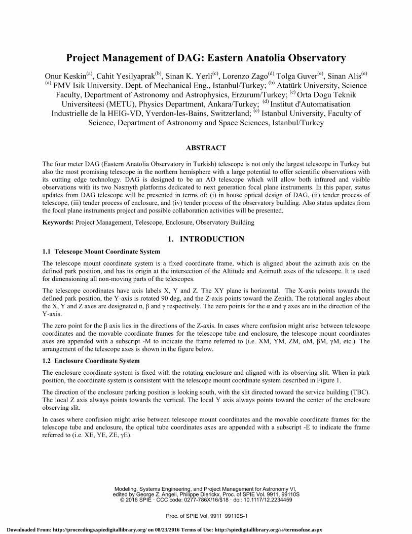
The telescope coordinates have axis labels X, Y and Z. The XY plane is horizontal. The X-axis points towards the defined park position, the Y-axis is rotated 90 deg, and the Z-axis points toward the Zenith. The rotational angles about the X, Y and Z axes are designated α, β and γ respectively. The zero points for the α and γ axes are in the direction of the Y-axis.
The zero point for the β axis lies in the directions of the Z-axis. In cases where confusion might arise between telescope coordinates and the movable coordinate frames for the telescope tube and enclosure, the telescope mount coordinates axes are appended with a subscript -M to indicate the frame referred to (i.e. XM, YM, ZM, αM, βM, γM, etc.). The arrangement of the telescope axes is shown in the figure below.
1.2 Enclosure Coordinate System
The enclosure coordinate system is fixed with the rotating enclosure and aligned with its observing slit. When in park position, the coordinate system is consistent with the telescope mount coordinate system described in Figure 1.
The direction of the enclosure parking position is looking south, with the slit directed toward the service building (TBC). The local Z axis always points towards the vertical. The local Y axis always points toward the center of the enclosure observing slit.
In cases where confusion might arise between telescope mount coordinates and the movable coordinate frames for the telescope tube and enclosure, the optical tube coordinates axes are appended with a subscript -E to indicate the frame referred to (i.e. XE, YE, ZE, γE).
Modeling, Systems Engineering, and Project Management for Astronomy VI, edited by George Z. Angeli, Philippe Dierickx, Proc. of SPIE Vol. 9911, 99110S
© 2016 SPIE · CCC code: 0277-786X/16/$18 · doi: 10.1117/12.2234459
Proc. of SPIE Vol. 9911 99110S-1
Downloaded From: http://proceedings.spiedigitallibrary.org/ on 08/23/2016 Terms of Use: http://spiedigitallibrary.org/ss/termsofuse.aspx
Figure 1. Orientation of the telescope coordinates
2. TELESCOPE REQUIREMENTS 2.1 Optical Tube Coordinate System
The optical tube coordinate system applies to the telescope tube, which is the main body of the telescope holding the primary (M1), and secondary (M2) mirrors and such. When in park position, the coordinate system is consistent with the telescope mount coordinate system described in Figure 1.
The local Z axis always points towards the line of sight. As the telescope is pointed off-zenith towards zenith angle of 90 degrees (or an elevation angle of zero, horizon pointing), the positive Y axis points up (to zenith for a horizon pointing telescope). The Z axis then points towards the horizon in the direction of the telescope pointing as the telescope moves toward horizon pointing (elevation angle of zero). This provides the local coordinates used by the M1, M2 and M3 assemblies and any other items mounted to the telescope tube.
In cases where confusion might arise between telescope coordinates and the movable coordinate frames for the telescope tube and enclosure, the optical tube coordinates are appended with a subscript -T to indicate the frame referred to (i.e. XT, YT, ZT).
2.2 Reference to Optical Design
The principle optical schematics of the telescope is illustrated in Figure 2. The telescope shall provide two Nasmyth foci but no Cassegrain focus. Table 1 gives the nominal design of the telescope configuration, for three values of the primary mirror f-number specification range, and a primary mirror diameter of 4 m. These numbers are indicative of the final optical configuration.
1. Radius of curvature and distances between mirrors vertex are given in absolute value. 2. Distances are defined along optical axis, from vertex to vertex 3. Entrance pupil of the telescope is the primary mirror. 4. Primary mirror thickness is indicative and values given here ensure that lateral supports contact points, collocated
with the plane of the center of gravity of the mirror. Lateral support contact points are at the mid height between the height of the vertex and the height of the meniscus, on the mirror edge. In this configuration lateral supports need only to apply forces in the mirror plane and not in the axial direction as well.
2.3 Optical System Requirements
Specifications were derived assuming that M1 is a thin mirror controlled in shape and position by an active optics (aO) system, consisting of a number of axial and lateral actuators. It nonetheless also applies to other mirror types (segmented, semi-rigid, etc.).
Proc. of SPIE Vol. 9911 99110S-2
Downloaded From: http://proceedings.spiedigitallibrary.org/ on 08/23/2016 Terms of Use: http://spiedigitallibrary.org/ss/termsofuse.aspx

Parameters constant to all designs - units [mm]FT/Dl FT D1 A3 B3 M1M3 M3F
14 [-] 56000 4000 425 300 -1000 4200
Primary mirrorF1 /D1 1.6 1.7 1.8 1.9 2.0 -
F1 6400 6800 7200 7600 8000 [mm]
R1 -12800 -13600 -14400 -15200 -16000 [mm]
K1 -1.004750 -1.005585 -1.006512 -1.007535 -1.008658 -
Secondary mirror - mirror diameter is for an unvignetted FoV of 30'F2/D2 1.7 1.8 1.9 2.0 2.2 -
D2 662.643 686.835 710.720 734.305 757.596 [mm]
F2 -1111.663 -1232.458 -1359.618 -1493.217 -1633.333 [mm]R2 -2223.325 -2464.916 -2719.236 -2986.434 -3266.667 [mm]
K2 -1.627157 -1.680976 -1.737038 -1.795454 -1.856341e 0.166 0.172 0.178 0.184 0.189
Mirrors separationsM1M2 -5415.385 -5717.197 -6015.190 -6309.434 -6600.000 [mm]
M2M3 4415.385 4717.197 5015.190 5309.434 5600.000 [mm]
Normalized parametersk 0.153846 0.159236 0.164557 0.169811 0.175000
m2 8.750000 8.235294 7.777778 7.368421 7.000000p 0.173697 0.181244 0.188836 0.196476 0.204167ß 0.500000 0.470588 0.444444 0.421053 0.400000
4000
2000
o
-2000
-4000
M2
N2
M3
F,/D,=1.8
N1
M1 -
-8000 -6000 -4000 -2000 o
Table 1. Nominal design of the DAG telescope configuration
Specifications also consider the presence of an adaptive optics (AO) system – not part of the telescope delivery – which may be able to correct residual static errors, to some extent (as determined by the AO actuators stroke). Nevertheless, specifications are made such that the telescope will be a seeing limited telescope when operating in seeing limited mode, and a diffraction limited telescope when operating in AO correction mode.
Figure 2. The actual optical schematic is defined in accordance to requirements
Proc. of SPIE Vol. 9911 99110S-3
Downloaded From: http://proceedings.spiedigitallibrary.org/ on 08/23/2016 Terms of Use: http://spiedigitallibrary.org/ss/termsofuse.aspx

Table 2. Optical System Requirements of DAG Telescope Primary mirror clear aperture (D1): 4.0 m;
Primary mirror focal ratio (f1): 1.8
Configuration: Ritchey-Chretien (RC) M1 and Μ2 are hyperboloids with conic constants matched to cancel off-axis coma and spherical aberration.
Focal Planes Two Nasmyth foci. No Cassegrain focus
Effective focal length: 56 m
Operational waveband: 350 to 3000 nm
Unvignetted FOV (diameter): 30 arcmin available at the Nasmyth foci
Primary science FOV: 10 arcmin
Number, location of Nasmyth foci: Two foci, located 4.2 m after M3
The AO system foreseen for the DAG telescope has a deformable mirror with an inter-actuator distance (ΛΑΟ) of 0.4 m, as projected in the entrance pupil plane (M1). According to Nyquist/Shannon sampling theorem, wavefront errors at spatial scales shorter than twice the inter-actuator distance, i.e. 0.8 m, cannot be corrected. The AO system cutoff spatial frequency is therefore defined as the spatial frequency associated to the inter-actuator sampling, 1/(2ΛΑΟ).
Because the deformable mirror actuators grid is generally square, the AO correction domain in the spatial frequency space also has a square shape. Wavefront aberrations which can be described with spatial frequencies inside the square are defined as low order WFE, while wavefront aberrations that are located outside this domain are designed as high order WFE. It is clear that low order WFE could in principle be seen and then corrected by the AO system wavefront sensor (WFS), while the high order ones could not.
This being said, because it is not certain that the future AO system geometry will be square, and because it simplifies specifications, we will assume here that the low frequency corrected domain is circular, therefore the cutoff frequency will be defined for all directions inside the pupil, not only for two given orthogonal directions.
In this respect, demonstration of the low order and high order residual wavefront errors specifications are met regardless of the direction of measure inside the entrance pupil.
2.4 Secondary Mirror
The secondary mirror M2 will be a convex mirror controlled in five degree of freedom: decentering, piston, and tip-tilt relative to the vertex. The alignment mechanism will have the following requirements:
Table 3. Alignment mechanism requirements of DAG telescope Focus (Δz) Decenter (Δx, Δy) Tip-tilt (θx, θy) Absolute Accuracy 10 μm 20 μm 20 arcsec Incremental accuracy referred to a 20 μm focus move 2.5 μm 5 μm 5 arcsec
The range along all degrees of freedom are adequate to ensure at the Nasmyth foci the image optical quality specified in terms of WFE, under all applicable gravity and thermoelastic deformations experienced by the telescope.
On-axis aberrations generated by M2 misalignment within the specified incremental accuracy, as seen from the focal plane (defocus, astigmatism, 3rd order coma and spherical) is expected to be significantly smaller than the on-axis WFE budget. Off-axis aberrations generated by M2 misalignment as seen from the focal plane will be significantly smaller than the expected off-axis astigmatism for the Ritchey-Chretien configuration, over the 10’ science FOV.
Proc. of SPIE Vol. 9911 99110S-4
Downloaded From: http://proceedings.spiedigitallibrary.org/ on 08/23/2016 Terms of Use: http://spiedigitallibrary.org/ss/termsofuse.aspx

2.5 Tertiary Mirror
The tertiary mirror M3 will be a flat, elliptical mirror, inclined at 45 deg with respect to the telescope optical axis. It will be actively aligned along piston (telescope axis) and tip-tilt. The range along all degrees of freedom are adequate to ensure at the Nasmyth foci the image optical quality specified in terms of WFE, under all applicable gravity and thermoelastic deformations experienced by the telescope. The M3 mechanism shall have the following requirements:
Table 4. M3 mechanism requirements of DAG telescope
Piston (aligned along the ZT axis) Tip-tilt (Rx, Ry)
Absolute Accuracy 10 μm 20 arcsec Incremental accuracy
referred to a 20 μm focus move 2.5 μm 5 arcsec
2.6 General Applicable Requirements for M1, M2 and M3
Table 5. General applicable optical requirements of DAG telescope
Micro roughness Micro roughness shall be lower than 2 nm rms (goal 1 nm rms). The assumption is that micro roughness for the three mirrors add in quadrature, totalizing to 3.5 nm (1.7 nm goal).
Optical surface Scratches, pits and digs according to DIN3140: 5/6x0.4; K2x0.025
Reflectivity (coated optical surface):
Aluminum coating; 90% in [350-700 nm], 85% in [700-950 nm], 90% in [950-1050 nm], 95% in [1050-1300 nm], 97% in [1300-1800 nm], 98% in [1800-3000 nm].
2.7 Mechanical Requirements
Table 6. Mechanical requirements of DAG telescope Mounting: Altitude-Azimuth
Zenith blind spot (ZBS): ≤ 1 deg Zenith angle
Azimuth range >= ± 270 deg
Altitude range (in maintenance mode) αM = –90 to +90 deg
Altitude range (in observing mode) Zenith Angle = ZBS to 70 deg
"Locked" system (structural) eigenfrequencies > 8 Hz
Slew speed 2 deg/sec + 8 second settling time
Pointing accuracy, absolute (blind pointing error)
< 2 arcsec for any point in the sky with Zenith angle < 70 deg,
Pointing accuracy, incremental < 0.1 arcsec for a 10 arcmin offset in any direction
Tracking accuracy, open loop rms < 0.1 arcsec for one minute
Tracking accuracy, closed loop with rms < 0.1 arcsec for one hour under maximum telescope wind
Proc. of SPIE Vol. 9911 99110S-5
Downloaded From: http://proceedings.spiedigitallibrary.org/ on 08/23/2016 Terms of Use: http://spiedigitallibrary.org/ss/termsofuse.aspx

autoguider load
• Maximum mean wind speed: U = 4 m/s
• Turbulence intensity: σu/U = 0.2
• Turbulence scale: L = 2 m
• Wind power density according to the Von Karman spectrum:
with n = frequency (Hz),
Secondary mirror alignment The support mechanism will provide fine alignment along 5 degrees of freedom: piston, tip-tilt, x- and y-center.
Tertiary mirror flip and alignment The mechanism will provide the following functions: • Switching the light beam to alternate Nasmyth foci
• Fine alignment along 3 degrees of freedom: piston (ZT axis), tip-tilt
Instrument Nasmyth flanges (Figure 3) Load capability: 2000 kg located 1.7 m from the flange and attached to it, plus 2000 kg as equipment laying on the platform itself, with center of gravity at its center.
Instrument envelope (Figure 3) Load capability: 2000 kg located 1.7 m from the flange and attached to it, plus 2000 kg as equipment laying on the platform itself, with center of gravity at its center.
Figure 3. DAG telescope design
Proc. of SPIE Vol. 9911 99110S-6
Downloaded From: http://proceedings.spiedigitallibrary.org/ on 08/23/2016 Terms of Use: http://spiedigitallibrary.org/ss/termsofuse.aspx

3. ENCLOSURE REQUIREMENTS 3.1 General Applicable Requirements of DAG Enclosure
Table 7. General requirements of DAG enclosure
Free inner volume:
a. Half sphere centered at X,Y,Z=0 with radius (upward)=7.0 m
b. Cylinder below this half sphere of radius=7.0 m and height=3.065 m
c. Cylinder centered at X=0, Y=5.6 m, with radius (directed along Y) =2.5 m, top not lower than Z=3 m, free volume all the way downward. This free volume shall be provided for one particular angular position of the rotating enclosure.
d. The overall free height shall include all margins required by the hook of the overhead crane to access all points of the above defined volume.
Azimuth track Circular azimuth track centered on the telescope azimuth axis
Height (position) of azimuth track –4 m from Z=0 level Slit width 4.5 m Minimum free elevation angle of view of telescope for a 4-m diameter light beam centered at X,Y,Z=0 10.5 deg
Minimum free elevation angle of telescope for maintenance. 0.0 deg
3.2 Mechanical Requirements of DAG Enclosure
Table 8. Mechanical requirements of DAG enclosure Rotation range ± 275 deg Maximum rotation (slew mode) speed adjustable up to 2 deg/sec + 8 second settling time Rotation accuracy, absolute (blind pointing error) < 1 deg
Rotation accuracy, incremental < 0.1 deg for a 5 deg offset in any direction Rotation accuracy, closed loop with feedback signal < 0.05 deg for one hour (with a smooth operation)
Slit doors opening/closing time < 2 minutes
Overhead crane travel Along YE axis: YE from –7.0 m to +7.0 m Along XE axis: XE from –2 m to +2 m
Overhead crane load 6.5 metric tons Lifetime profile 30 azimuth revolutions at maximum speed per day
4. PIER INTERFACE REQUIREMENTS The pier characteristics are defined by the telescope manufacturer (AMOS) to withstand the followings:
• With the telescope dummy fixed on the pier with 24 points, with only translational constraints, the first three eigenfrequencies of the system is higher than: (i) 8.07Hz bending in X direction; (ii) 8.22Hz rotation around Z axis; (iii) 9.71Hz bending in Y direction.
• The minimum local stiffness values under each mechanical jack are: (i) Vertical stiffness: 1.5e9 N/m; (ii) Lateral stiffness: 2.0e8 N/m
• total vertical load: 858kN (dead load), 1950kN (survival), -236kN (upward, survival)
Proc. of SPIE Vol. 9911 99110S-7
Downloaded From: http://proceedings.spiedigitallibrary.org/ on 08/23/2016 Terms of Use: http://spiedigitallibrary.org/ss/termsofuse.aspx
• total lateral load applied at 1836mm above the pier interface: 3kN (due to wind), 1250kN (survival due to seism and wind simultaneously)
• total torsion torque applied on the top pier: 14kNm (due to the azimuth telescope motor)
5. OBSERVATORY REQUIREMENTS 5.1 Enclosure Support Building
Table 9. Enclosure support building requirements
Main functions:
3-floor building surrounding the telescope pier: 1. Pier floor: access to pier 2. Base floor: access to building, maintenance labs 3. Observing floor: access to telescope and instruments 4. Topped by the rotating enclosure circular support slab Thermal control of telescope volume by forced ventilation.
Enclosure support top surface (interface with anchorages the enclosure support track):
Circular slab of - outer diameter 16 m - inner diameter 14 m, with a 5-m wide hatch in correspondence with the slit in parking position. Located 2 m below reference origin (altitude axis)
Observing floor
Circular slab of - outer diameter 16 m - inner diameter 7 m Located 4 m (TBC) below reference origin (altitude axis)
Pier height from foundation slab imbedded in solid ground 3 m
Building foundation Separate from pier foundation
5.2 Maintenance and Control Building
Table 10. Maintenance and control building requirements
Main functions:
Multi-functional building adjacent to the enclosure building, providing 1. In/outlet of telescope optical units (M1, M2, M3) by an
elevator, providing access to enclosure base and observing floors.
2. Storage, cleaning and coating plant for telescope optics. Handling crane for all M1, M2, M3 operations.
3. Observatory control room 4. Vehicle storage (garage) for a middle size van. 5. Workshop 6. Living facilities: dorms, canteen, infirmary
Building foundation Separate from enclosure foundation Optics handling requirement Defined by M1 cell: 5x5x2 m, 10 tons Volume for optics storage, cleaning and coating plant
At least 12x8x4 m, with direct access to the outside. The height specified is meant under the hook of the crane.
Control room 25 m2 Workshop 30 m2 Vehicle storage 25 m2, with direct access to the outside
Living facilities Dorms: 4 rooms, each 20 m2 Canteen: 30 m2 Infirmary: 20 m2
Proc. of SPIE Vol. 9911 99110S-8
Downloaded From: http://proceedings.spiedigitallibrary.org/ on 08/23/2016 Terms of Use: http://spiedigitallibrary.org/ss/termsofuse.aspx
Greenjiouse& ReverseTrombe Wall
Entwine
I
imuth,Floor, -74:1 ,II r ` Intermdiatey i Floor:,' oun dl Floor
_-'l
Sun Shaders
FitneseCente
6. CURRENT STATUS 6.1 Telescope
• Telescope FDR has been successfully passed with compliance to technical specifications. • M1 mirror blank is to be delivered by mid-August 2016. • Procurement of the main orders by AMOS is undergoing.
6.2 Enclosure
• Enclosure PDR passed with compliance to technical specifications. • FDR will take place by mid-July 2016. • Manufacturing of the embedded plates is expected by the first week of August 2016.
6.3 Pier
• The pier design proposed by GUNARDA and PROMER has been checked by EIE and AMOS about the local stiffness at the interface level with the mechanical jacks and about the dynamical behavior.
• The local stiffness requirements are fulfilled. • Pier manufacturing will be finalized by September 2016.
6.4 Observatory Building
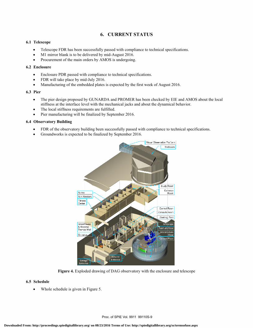
• FDR of the observatory building been successfully passed with compliance to technical specifications. • Groundworks is expected to be finalized by September 2016.
Figure 4. Exploded drawing of DAG observatory with the enclosure and telescope
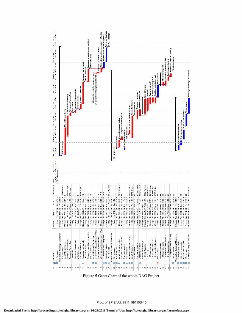
6.5 Schedule
• Whole schedule is given in Figure 5.
Proc. of SPIE Vol. 9911 99110S-9
Downloaded From: http://proceedings.spiedigitallibrary.org/ on 08/23/2016 Terms of Use: http://spiedigitallibrary.org/ss/termsofuse.aspx
esso
rs
31 d
ays
days
lay
days
10 d
ays
20 d
ays
20 d
ays
1 w
ks
1 da
ys
30 d
ays
10 d
ays
0 da
ys0
days
5 da
ys
5 da
ys
1 w
k
2015
Hal
f 2, 2
015
MIA
IMIJ
JIA
ISIO
INID
I TO
Tol
os^o
po
T
lalf
1, 2
016
alf 2
, 201
6al
f 1, 2
017
alf 2
, 201
7H
alf 1
, 201
8JIFIMIAIMIJ JIAISIOINID JIFIMIAIMIJ JIAISIOINID
JIF
IMIA
IMIJ
FD
R T
eles
cop'
a
1Mou
nt M
anuf
actu
rirjg
Tel
esco
pe P
re -
asse
mbl
y
Tel
esco
pe F
acto
ry T
gst
Mou
nt
Tel
esco
pe D
isas
sem
bly
SR
R T
eles
cope
Tra
nspo
rt T
eles
cope
Hal
f 2, 2
018
alf 1
, 201
9H
alf 2
, 201
9H
JIA
ISIO
I NID
JIF
IMIA
IMIJ
JIA
ISIO
INID
Tel
esco
pe p
arts
sta
ndß
yU
PC
K T
eles
cope T
eles
cope
unp
acki
ng a
nd e
rect
ion
ER
EC
Tel
esco
peM
2 an
d M
rea
dy fo
r sh
ipm
ertt
M1
mirr
or F
inal
Acc
epta
nce
at L
OS
Tr.
nsp
ortto
St-
Pet
ersb
ourg
Mirr
ois
tran
spor
t to
obse
rvat
ory
- A
TA
SA
MM
1 an
d ot
her
optic
s in
tegr
atio
nT
eles
cope
fina
l AIV
PA
C T
eles
cope
- E
nclo
sure
R E
rlosu
re Man
uf. E
mbe
dded
pla
tes
ansp
ort e
mbe
dded
pla
tes
Pie
rs d
esig
n re
view
R E
nclo
sure
Tm
Inst
alla
tion
embe
dded
pla
tes
Man
uf. E
nclo
sure
F)SR
Ren
clos
ure
Tra
nspo
rt e
nclo
sure
Unp
acki
ng e
nclo
sure
Dom
e S
truc
ture
Cla
ddin
gM
echa
nism
s pa
rt 1
Pla
nt In
stal
latio
n pa
ri 1
Ele
ctric
al In
stal
latio
n pa
rt 1
Win
ter
paus
e
B41
1din
gs d
esig
n re
view
Civ
il w
orks
con
trac
ting
and
conc
rete
wor
ksii
Win
ter
paus
e
Mec
hani
sms
part
2E
lect
rical
Inst
alla
tion
part
2
ePre
Com
mis
sion
ing
Acc
epta
nce
Tes
ts &
Tra
inin
gT
PA
C e
nclo
sure
Bui
ldin
gs fi
nish
ing
and
serv
ices
AS
Dur
atio
nS
tart
Fin
ish
Pre
dec
1 da
yT
hu 5
.03.
15T
hu 5
.03.
15
900
days
Mon
25.
01.1
6F
rl 5.
07.1
91F
S +
2:
3
1 da
y
228
days
Mon
25.
01.1
6M
on 2
5.01
.16
Tue
26.
01.1
6T
hu 8
.12.
16
165
days
25 d
ays
Fri
9.09
.16
Thu
27.
04.1
74F
S-6
5
5FS
-1
1
6
Thu
27.
04.1
7W
ed 3
1.05
.17
1 da
yT
hu 1
.06.
17T
hu 1
.06.
17
20 d
ays
Fri
2.06
.17
Thu
29.
06.1
7 7
1 da
yF
ri 30
.06.
17F
ri 30
.06.
17 8
45 d
ays
Mon
10.
07.1
7F
ri 8.
09.1
7 9F
S +
5
180
days
Mon
11.
09.1
7F
ri 18
.05.
1810
1 da
yM
on 2
1.05
.18
Mon
21.
05.1
8 11
106
days
Mon
21.
05.1
8M
on 1
5.10
.18
11
1 da
yT
ue 1
6.10
.18
Tue
16.
10.1
8 13
0 da
ysF
ri 10
.08.
18F
ri 10
.08.
18
0 da
ysF
ri 31
.08.
18F
ri 31
.08.
18
10 d
ays
Fri
31.0
8.18
Thu
13.
09.1
816
30 d
ays
Fri
14.0
9.18
Thu
25.
10.1
8 17
;15
55 d
ays
Fri
26.1
0.18
Thu
10.
01.1
9 13
;18
115
days
Fri
11.0
1.19
Thu
20.
06.1
919
1 da
yF
ri 5.
07.1
9F
ri 5.
07.1
9 20
F5
+'
739
days
Tue
1.1
2.15
Frl
28.0
9.18
1 da
yT
ue 1
.12.
15T
ue 1
.12.
15
1 da
yF
ri 25
.03.
16F
ri 25
.03.
16
61 d
ays
Mon
25.
04.1
6M
on 1
8.07
.162
4FS
+:
29 d
ays
Tue
19.
07.1
6F
ri 26
.08.
16 2
5
1 m
onF
ri 25
.03.
16T
hu 2
1.04
.16
1 da
yF
ri 15
.07.
16F
ri 15
.07.
16
34 d
ays
Mon
26.
09.1
6T
hu 1
0.11
.162
6FS
+:
36 w
ksM
on 1
5.08
.16
Fri
21.0
4.17
28F
S +
,
1 da
yM
on 2
4.04
.17
Mon
24.
04.1
730
70 d
ays
45 d
ays
133
days
118
days
Mon
27.
03.1
7F
ri 30
.06.
17 3
1 F
S -
2
Mon
8.0
5.17
Mon
22.
05.1
7
Fri
7.07
.17
32S
S +
:
Wed
22.
11.1
7M
on 2
2.05
.17
Wed
1.1
1.17
33S
S+
100
days
Thu
29.
06.1
7W
ed 1
5.11
.173
5F5
-9
45 d
ays
Thu
21.
09.1
7W
ed 2
2.11
.17
35F
S-3
40 d
ays
Thu
28.
09.1
7W
ed 2
2.11
.17
37S
S+
40 d
ays
Thu
28.
09.1
7W
ed 2
2.11
.17
37S
S +
,
20 w
ksT
hu 2
3.11
.17
Wed
11.
04.1
839
100
days
Thu
12.
04.1
8W
ed 2
9.08
.184
0
30 d
ays
Thu
12.
04.1
8W
ed 2
3.05
.184
0
40 d
ays
Thu
12.
04.1
8W
ed 6
.06.
1840
30 d
ays
Thu
7.0
6.18
Wed
18.
07.1
843
30 d
ays
Thu
19.
07.1
8W
ed 2
9.08
.184
4
1 da
yF
ri 28
.09.
18F
ri 28
.09.
1845
433
days
Wed
23.
03.1
6F
ri 17
.11.
178w
ksW
ed 2
3.03
.16
Tue
17.
05.1
6
2 m
ons
Wed
18.
05.1
6T
ue 1
2.07
.164
84
mon
sT
ue 2
6.07
.16
Mon
14.
11.1
6
5 m
ons
Mon
26.
12.1
6F
ri 12
.05.
1750
6.5
mon
sM
on 2
2.05
.17
Fri
17.1
1.17
51F
5+'
IDT
ask
Nam
e
TO
- T
eles
cope
Con
trac
tual
Tel
esco
pe M
ilest
ones
FD
R T
eles
cope
Mou
nt M
anuf
actu
ring
Tel
esco
pe P
re -
asse
mbl
y
Tel
esco
pe F
acto
ry T
est
DR
R M
ount
Tel
esco
pe D
isas
sem
bly
SR
R T
eles
cope
Tra
nspo
rt T
eles
cope
Tel
esco
pe p
arts
sta
ndby
UP
CK
Tel
esco
pe
Tel
esco
pe u
npac
king
and
ere
ctio
nE
RE
C T
eles
cope
M2
and
M3
read
y fo
r sh
ipm
ent
M1
mirr
or F
inal
Acc
epta
nce
at L
ZO
:
Tra
nspo
rt to
St-
Pet
ersb
ourg
Mirr
ors
tran
spor
t to
obse
rvat
ory
-AT
44 45 46 47 48 49 50 51 52
®M
1 an
d ot
her
optic
s in
tegr
atio
n
®T
eles
cope
fina
l AIV
PA
C T
eles
cope
Con
trac
tual
Enc
losu
re M
ilest
ones
TO
- E
nclo
sure
PD
R E
nclo
sure
@__
Man
uf. E
mbe
dded
pla
tes
Tra
nspo
rt e
mbe
dded
pla
tes
Pie
rs d
esig
n re
view
FD
R E
nclo
sure
Inst
alla
tion
embe
dded
pla
tes
Man
uf. E
nclo
sure
SR
R e
nclo
sure
Tra
nspo
rt e
nclo
sure
Unp
acki
ng e
nclo
sure
Ere
ctio
n en
clos
ure_
?D
ome
Str
uctu
re
Cla
ddin
gM
echa
nism
s pa
rt 1
Pla
nt In
stal
latio
n pa
rt 1
Ele
ctric
al In
stal
latio
n pa
rt 1
Win
ter
paus
eE
nclo
sure
fina
l AIV
Mec
hani
sms
part
2E
lect
rical
Inst
alla
tion
part
2
Pre
Com
mis
sion
ing
Acc
epta
nce
Tes
ts &
Tra
inin
gP
AC
enc
losu
re
Con
trac
tual
Bui
ldin
g M
ilest
ones
Bui
ldin
gs d
esig
n re
view
Civ
il w
orks
con
trac
ting
Site
and
con
cret
e w
orks
Win
ter
paus
e
INB
uild
ings
fini
shin
g an
d se
rvic
es
Figure 5 Gantt Chart of the whole DAG Project
Proc. of SPIE Vol. 9911 99110S-10
Downloaded From: http://proceedings.spiedigitallibrary.org/ on 08/23/2016 Terms of Use: http://spiedigitallibrary.org/ss/termsofuse.aspx

7. FUTURE WORK As the largest telescope project moves forward, the additional FPI project has just been funded by the Ministry of Development of Turkey. DAG team, within this short time scale and in collaboration of four national universities, has started the FPI project. The Project will be coordinated by Ataturk University Astrophysics Research and Application Centre (ATASAM) which was founded in 2012 and is responsible for most of the astrophysical, and electro-optical research funded by the Ministry of Development. There will be three supporting laboratories which will be established within the framework of the DAG-FPI project. These laboratories will be established at the following universities: i) FMV Isik University (for AO and DR research and development); ii) Orta Dogu Teknik Universitesi/METU (calibration laboratory); iii) Istanbul University (MKID).
Currently, desired type of instruments for the DAG telescope is given in Table 11. At the moment, there expected to be one AO supported focus at the telescope. However, DAG team is investigating the possibilities for building a second AO system for the other focus as well. This, in principle, is possible as the AO system (including DR) will be built in Turkey at FMV Isik University.
Table 11. DAG FPI Instruments Focus Instrument No Wavelength Type Local Contribution (%) Int. Contribution (%) N1/N2 - DR 50 50
N1 - AO 90 10 N1 A VIS IMG 95 5 N1 B NIR IMG 95 5 N1 C VIS+NIR NT - 100 N2 A VIS SPEC 80 20 N2 B NIR SPEC 80 20 N2 C ? ? ? 100?
N1: AO hosting focus; N2: Non-AO focus; DR: Derotator; AO: Adaptive Optics; NIR: Near-IR; IMG: Imaging; SPEC: Spectroscopy; MOS: Multi-object Spectroscopy; NT: New technology detectors
The main purpose of the DAG-FPI project is to obtain first generation instruments for the DAG telescope. This includes optical and near-infrared detectors and both for imaging and for spectroscopy. Since the national observatory of Turkey has been operational, Turkish astronomical community is well familiar with FOSC instruments built by the Copenhagen University. This kind of instruments (FOSC series, FORS2@VLT etc) are generally the workhorses of observatories. In this respect, a multi purpose instrument for optical and its equivalent in near-infrared are desired. These two instruments most likely will be installed at the Nasmyth-2 focus where the AO system will not be operational. But depending on the discussions that will undergo before the commissioning and even during the building of the instruments, these multi purpose instruments can be installed at the Nasmyth-1 focus. The need for AO both for imaging and spectroscopy is driven mainly by the scientific rationale of the DAG project, and broad research interests of the Turkish astronomical community.
The design of the telescope is made so that each Nasmyth focus can hold three instruments up to a total weight of 2000 kg. N1 will be equipped with an AO system for the moment. A brief overview of the expected instrument distribution for the two foci is given below:
N1-a: An imager (can be metal oxide semiconductors) for the optical wavelengths where high resolution imaging is needed.
N1-b: A NIR imaging detector. Depending on science cases this instrument can be used with or without AO given the typical field-of-view of such detectors are quite small already.
N1-c: A microwave kinetic inductor detector as a new technology instrument will likely be placed. This will be operated around at temperatures of 100 mK and allow observing from optical to near-infrared wavelengths.
N2-a: DAG Project team has decided to obtain a spectrograph which willl operate between 350-1000 nm with resolutions between 100-3000. This instrument is expected to be a workhorse for the Turkish astronomical community.
Proc. of SPIE Vol. 9911 99110S-11
Downloaded From: http://proceedings.spiedigitallibrary.org/ on 08/23/2016 Terms of Use: http://spiedigitallibrary.org/ss/termsofuse.aspx
N2-b: As DAG will be the first and largest telescope to operate in the near-IR in Turkey, spectroscopy will be very crucial. This instrument will enable Turkish astronomers to work in the wavelength range of 0.9 – 2.5 microns.
N2-c: Although it is desired to have a multi-object spectrograph (if not possible with N2-a), this instrument slot can be reserved for future collaborations.
This ambitious project will not only serve to national but also to the international astronomical communities. At this stage, all kind of scientific and technical collaborations are very welcome and expected.
ACKNOWLEDGEMENTS
Authors would like to thank Republic of Turkey, Ministry of Development; FMV Işık University, Istanbul/Turkey; Atatürk University, Erzurum/Turkey (Project No: 2011K120230, 2016K121140); Orta Doğu Teknik Üniversitesi, Ankara/Turkey (Project No: 2016K121380); Haute Ecole d'Ingénierie et de Gestion du Canton de Vaud (HEIG-VD), Yverdon-les-Bains/Switzerland; Istanbul University, Istanbul/Turkey (Project No: 2016K121370); Atatürk University, Erzurum/Turkey, Astrophysics Research and Application Center (ATASAM), Erzurum/Turkey; FMV Işık University, Center of Optomechatronics Application and Research (OPAM), Istanbul/Turkey; Istanbul University Observatory Research and Application Center (IUGUAM), Istanbul/Turkey; for their support throughout the DAG project.
Proc. of SPIE Vol. 9911 99110S-12
Downloaded From: http://proceedings.spiedigitallibrary.org/ on 08/23/2016 Terms of Use: http://spiedigitallibrary.org/ss/termsofuse.aspx