project final report - trimis.ec.europa.eu · average 12% less fuel than their late 1990-ies...
TRANSCRIPT

Project Final Report (FTR-5-93) 1
PROJECT FINAL REPORT
Grant Agreement number: 213414
Project acronym: FUTURE
Project title: Flutter-Free Turbomachinery Blades
Funding Scheme: Collaborative project
Period covered: from July 1 2008 to June 30 2013
Name, title and organisation of the scientific representative of the project's coordinator:
Torsten Fransson, Prof., KTH
Tel: +46-790 7475
Fax: +46 20 4161
E-mail: [email protected]
Project website address: www.future-project.eu

Project Final Report (FTR-5-93) 2
1. Final publishable summary report
1. Executive summary
The propulsion of aircrafts is today almost exclusively based on turbomachinery-based engines, which is primarily due to their unprecedented power density. Turbomachines have progressively evolved since the middle of the last century and key advances have been made in increasing reliability, availability and environmental friendliness. Today’s aircraft engines consume on an average 12% less fuel than their late 1990-ies counterparts and are thanks to this much “greener”. Environmentally friendly aircraft engines are light, powerful, silent and produce low emissions of greenhouse gases and nitride oxides. This is achieved by having an efficient propulsion concept such as a high bypass ratio turbofan and by having an efficient power generation cycle. Reduced component counts and reduced weight of components among others are trends that make propulsion “greener”. There are however limits for how “green” and aircraft engine can become using traditional cycles, largely affected by mechanical integrity. Of many phenomena affecting the mechanical integrity of turbomachines, flutter is probably the most severe, as it can lead to the disintegration of components in very short time. Within the FUTURE project, the phenomenon of flutter in turbomachines is addressed in a combined experimental and numerical effort, such as to increase the accuracy and reliability of turbomachinery flutter predictions. The focus of the project is put on the two primary areas of turbomachines, in which flutter is observed as are i) low-pressure compressors and ii) low-pressure turbines. In the FUTURE project, a number of different aerodynamic test facilities are used as are: - Non-rotating compressor cascade rig with controlled oscillation of blades - Non-rotating turbine cascade rig with controlled oscillation of blades - Rotating compressor rig (1 ½ stage) - Rotating turbine rig (1 stage) In addition, the following mechanical test rigs are used to characterize mechanical damping:
- Rotating in vacuo test rig for measurement of structural properties of a blisk - Rotating in vacuo test rig for measurement of structural properties of a bladed disk with
cantilevered blades and interlocked blades State-of-the-art measurement techniques such as tip timing, optical vibration measurements, fast-response pressure transducers and Pressure-Sensitive Paint (PSP) have been used to characterize the structural properties and the unsteady aerodynamic behaviour during controlled oscillation and free flutter. Tests have been performed on a freely fluttering LPT rotor validating the potential for using structural mistuning to limit vibration amplitudes or suppress flutter completely. A variety of leading-edge computational activities have been performed in parallel to the experiments such as to validate numerical tools on high-quality test data acquired in the FUTURE project and to ultimately get a deeper understanding of the flutter phenomenon in turbomachines.

Project Final Report (FTR-5-93) 3
Summary description of project context and objectives
Project Context
In modern aircraft engine design, where the driving forces are increasing aircraft safety, lowering weight, raising performance and cost-effective manufacturing, the challenge is to optimize for conflicting aerodynamic and structural demands. Increasingly thinner, lighter, but more loaded blades substantially raise the vulnerability towards flow induced vibrations such as flutter, leading to a high damage potential. By advancing the state-of-the-art in flutter prediction capabilities and design rules, the FUTURE project will lead to short term benefits in terms of decreased development cost in current engine programs, reduced weight and thus fuel consumption, and increased ability to efficiently manage flutter problems occurring on engines at service.
Mid-term and long-term benefits are that improved analysis and design aeromechanical methods for aggressive lightweight blade design are an enabling factor for high efficiency future environmental friendly aero engines and gas turbines with maintained safety. In combination with a reduced time-to-market the project outcomes will have a strong impact on the competitiveness for the European aero engine module and stationary gas turbines manufacturers participating in the project. The project will give the partners access to experimental data that are not available in any other company in the world.
Project Technical Objectives
Design “Flutter-Free” Blades
Most of the cascade data available so far were obtained from generic experiments on two-dimensional attached subsonic and transonic flows with oscillating turbine and compressor cascade blades. New sets of data are now needed to further increase the understanding of the role played by the differences that exist between annular cascades and multistage configurations in the inception of flutter, data that FUTURE will supply. A parametric flutter study will be conducted for compressor profiles in a full annular oscillating cascade. A new suspension system capable of allowing for measurements of natural blade flutter will be used for the same compressor profiles in the annular cascade. An experimental parametric study on the blade aeroelastic behaviour will be carried out using oscillating rigid 3D blades in a sector annular cascade to study the influence of complex blade motions with the help of a pioneering excitation mechanism. As an additional effort to capture the physics observed in engine-realistic configurations, measurements on an innovative oscillating 3D flexible blade will also be conducted.
In order to assess the significance of the engine multi-row environment including wave reflections for the first time, a full scale VIGV-rotor-stator compressor test case will be designated to measure and assess sustained near flutter of the rotor.

Project Final Report (FTR-5-93) 4
The dependence of aeroelastic stability on relevant structural and aerodynamic parameters will be assessed in a full-scale single-stage rig using a blisk rotor that is representative of a modern ultra-high bypass fan design. The blade vibration will be actively controlled in terms of amplitudes and phases, allowing sophisticated aerodynamic measurement in great technical detail and with unprecedented flexibility concerning independent variation of the dominant parameters.
Breakthrough system for controlled forced vibration:
One device for excitation of a rotor in operation will be developed within the project.
The rotor will be designed so that no resonance-crossings occur in the operating range. Hence, one would not be able to assess the aerodynamic damping outside the flutter regime. The purpose of the controlled excitation device is to be able to excite rotor vibration to assess aerodynamic damping also in the stable regime.
The development of such a system is not only expected to lead to the advent of a new era in the experimental research of compressor and turbine aeroelasticity, it is also opens up for several new possibilities in the future. One is as a rational approach to investigate and assess the effect of incoming disturbances on turbomachinery performance and HCF. Another possibility is for investigation of using a similar device on an aircraft engine for active control of damping.
Leading-edge measurement techniques:
Within the FUTURE project various sophisticated state-of-the-art measurements techniques will be used, and further developed as well as validated. The novel PSP (Pressure Sensitive Paint) technique will significantly enhance the resolution and quality of the experimental results. The high quality experimental results will be essential for the validation and calibration of analysis and design tools and formulation of improved design rules. As experiments and numerical calculations will be performed simultaneously it will be possible to throughout the project identify experimental and/or numerical inaccuracies and thus during the experimental campaigns gain insight into the governing physical phenomena. This is an enormous advantage of having all the major European aeromechanical companies, research institutes and universities involved in the same project. The database to be established will be world-wide unique.
Validated aeromechanical design and analysis tools:
The currently available numerical tools will be verified and benchmark tests will be performed based on the new state-of-the-art experimental test data acquired in the FUTURE project, which include complex mode shapes, 3D and multi-row effects. This kind of data does till today not exist. Based on the assessment of prediction bottlenecks and the identification of the relevant flow physics and flutter controlling parameters, potential routes will be identified to improve the design and analysis tools and the methods will be calibrated accordingly.

Project Final Report (FTR-5-93) 5
2. Description of the main S&T results/foregrounds
WP1 – Turbine and Compressor Cascade Flutter
WP1 consisted in turbine and compressor cascade flutter experiment campaigns and provided detailed measurements of relevant aeroelastic properties in a simplified and well controlled
environment. The tests completed the more complex rotating rig experiments of WP 2 (CTA turbine rig) and WP3 (TUD compressor rig), and contributed to identify and isolate the effects of different aerodynamic and mechanical design parameters. Two state-of-the-art facilities were employed in
WP1, one at partner KTH and one at partner EPFL ( ).
Figure 1. Cascade test facilities used In particular three different experiment campaigns were performed with the following objectives:
(A) KTH Turbine Experiments (on new airfoil geometry) assess the impact of complex vibration modes on aeroelastic stability, by testing a 3D
rigid vs real deforming airfoil (requiring relatively high aspect ratio) and modes representative of rotor assemblies (requiring two Degree of Freedom (DoF) oscillation system, combining bending and torsion);
assess validity of the stability maps approach and related linear superposition principle on simplified as well as complex vibration modes;
apply and assess a novel type of Pressure Sensitive Paint (PSP) technique to measure timeresolved surface pressure, allowing high temporal and spatial resolution, such providing more detailed information on the unsteady flow behaviour.
(B) EPFL Turbine Experiments (on existing ADTurB cascade hardware)
assess the impact of assembly vibration modes on aeroelastic stability of packeted airfoils (two jointly in pair and stator segment of engine configurations), by testing blade clusters modes (requiring an annular cascade).

Project Final Report (FTR-5-93) 6
(C) EPFL Compressor Experiments (on new airfoil geometry) perform detailed measurements of the vibration induced unsteady blade loading
through controlled vibration experiments, complemented by assessment of the flutter boundaries under different flow situations in a freely vibrating cascade;
identify and study flutter boundaries and address non-linear flow phenomena specific to compressor stall flutter, by gathering detailed information on the aeroelastic behaviour in all blades free flutter (requiring an annular cascade).
KTH Turbine Experiments
KTH AETR (Aerolastic Test Rig) is a set up composed by an annular cascade with 5 blades. The flow is directed using elastic walls that allow the periodicity assessment of the cascade.
Figure 2. KTH annular sector cascade test facility
The middle blade is oscillated in 3 orthogonal rigid body modes. The oscillation is achieved using a mechanical actuator beneath the hub of the cascade, which provides control on the vibration mode and frequency of the oscillation.
The objective of the setup is to perform flutter experiments in the influence coefficient domain. Within this purpose the oscillating blade and the adjacent are instrumented with fast response pressure transducers at 3 different span positions (10% 50% 90%). The motion of the blade is real-time measured using a set of 3 lasers. Consequently the pressure and motion are synchronized within the same timeline which allows the stability analysis.
Project Final Report (FTR-5-93) 7
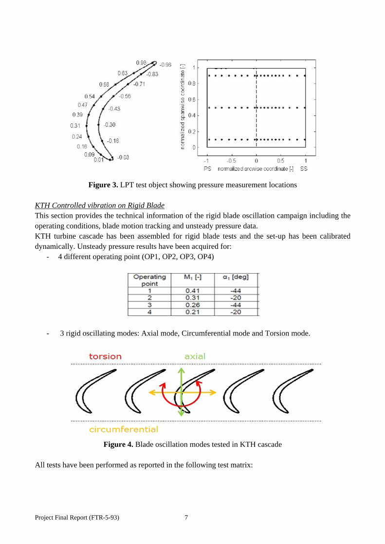
Figure 3. LPT test object showing pressure measurement locations
KTH Controlled vibration on Rigid Blade This section provides the technical information of the rigid blade oscillation campaign including the operating conditions, blade motion tracking and unsteady pressure data. KTH turbine cascade has been assembled for rigid blade tests and the set-up has been calibrated dynamically. Unsteady pressure results have been acquired for:
- 4 different operating point (OP1, OP2, OP3, OP4)
- 3 rigid oscillating modes: Axial mode, Circumferential mode and Torsion mode.
Figure 4. Blade oscillation modes tested in KTH cascade
All tests have been performed as reported in the following test matrix:
Project Final Report (FTR-5-93) 8
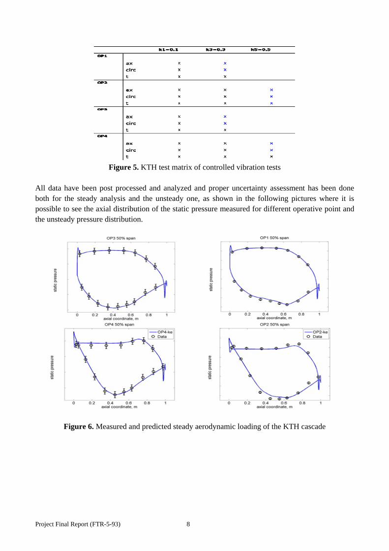
Figure 5. KTH test matrix of controlled vibration tests
All data have been post processed and analyzed and proper uncertainty assessment has been done both for the steady analysis and the unsteady one, as shown in the following pictures where it is possible to see the axial distribution of the static pressure measured for different operative point and the unsteady pressure distribution.
Figure 6. Measured and predicted steady aerodynamic loading of the KTH cascade

Project Final Report (FTR-5-93) 9
Figure 7. Steady and unsteady test data; correlation of CFD results
KTH Controlled vibration on Flexible Blade An elastic blade was designed, assembled and operated under restricted conditions and unsteady pressure measurements were performed using the unsteady PSP technique by partner Onera. However for safety reasons as well as due to limitations of the used measurement technique (PSP), the range of tested frequency was limited by an upper limit of 80Hz. This section gives an overview of the results obtained using the Pressure Sensitive Paint (PSP) as an innovative investigation method to the usual pressure taps to provide pressure images on the blade surface in a turbine cascade. To achieve unsteady PSP measurements, several parameters have to be adjusted, like the blade material, the optical access, the intensity of excitation lamp, but the main issue concerns the blade deformation leading to changes in measurement conditions. The Pressure Sensitive Paint (PSP) technique has been used in the KTH flutter cascade as an innovative measurement technique with the aim to provide more detailed description of the unsteady aerodynamics governing flutter on the surface blade, and to push this technique to a higher TRL (Technology Readiness Level) for turbomachinery application. During a first test campaign, PSP measurements have been performed on rigid blades where one blade was oscillating in a controlled manner. Then a second campaign has been done on a flexible blade.
Project Final Report (FTR-5-93) 10
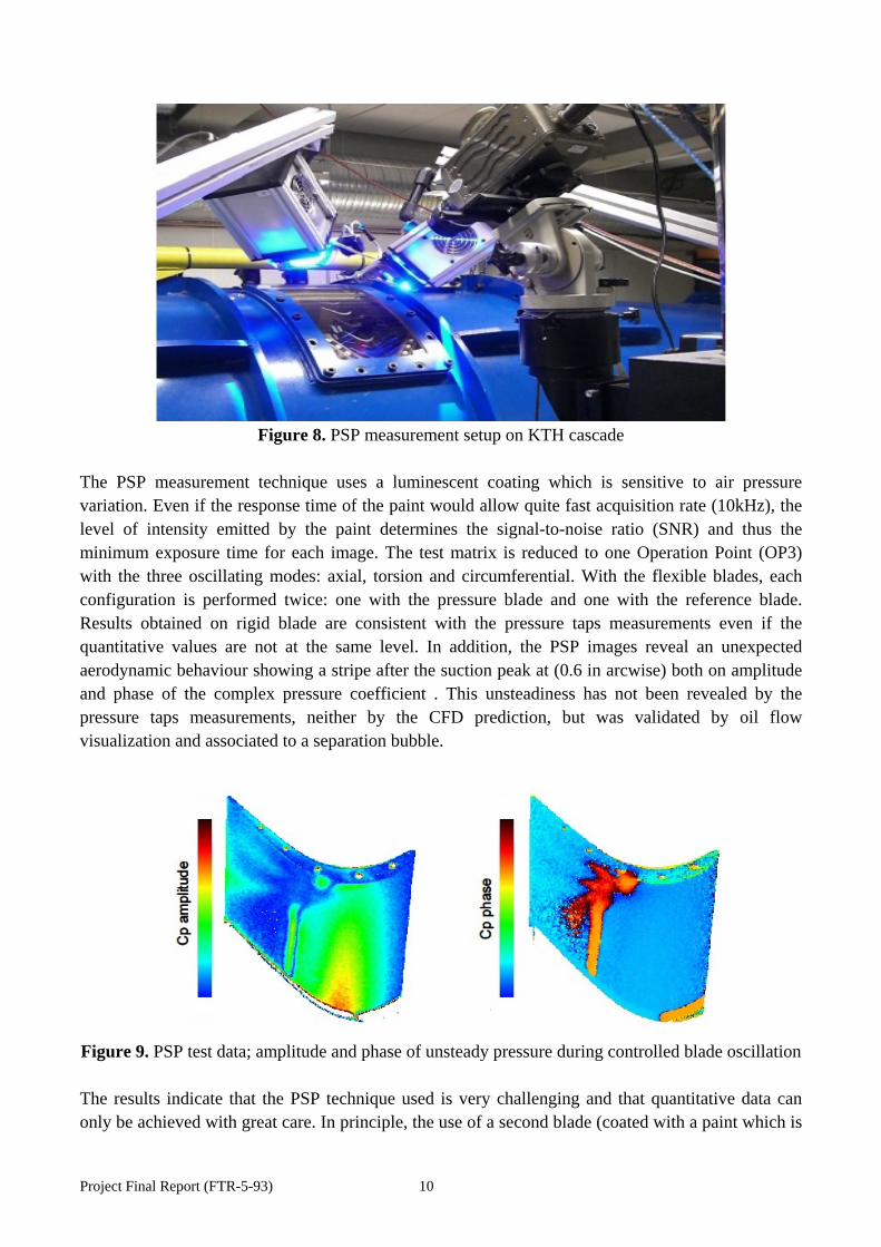
Figure 8. PSP measurement setup on KTH cascade
The PSP measurement technique uses a luminescent coating which is sensitive to air pressure variation. Even if the response time of the paint would allow quite fast acquisition rate (10kHz), the level of intensity emitted by the paint determines the signal-to-noise ratio (SNR) and thus the minimum exposure time for each image. The test matrix is reduced to one Operation Point (OP3) with the three oscillating modes: axial, torsion and circumferential. With the flexible blades, each configuration is performed twice: one with the pressure blade and one with the reference blade. Results obtained on rigid blade are consistent with the pressure taps measurements even if the quantitative values are not at the same level. In addition, the PSP images reveal an unexpected aerodynamic behaviour showing a stripe after the suction peak at (0.6 in arcwise) both on amplitude and phase of the complex pressure coefficient . This unsteadiness has not been revealed by the pressure taps measurements, neither by the CFD prediction, but was validated by oil flow visualization and associated to a separation bubble.
Figure 9. PSP test data; amplitude and phase of unsteady pressure during controlled blade oscillation The results indicate that the PSP technique used is very challenging and that quantitative data can only be achieved with great care. In principle, the use of a second blade (coated with a paint which is

Project Final Report (FTR-5-93) 11
insensitive to pressure) should be able to cope with the illumination variations due to blade deformation. But the processing of two set of images instead of one introduces additional noise on the images and no significant results can be obtained from these images.
EPFL Turbine Experiments
The Non-Rotating Annular Test Facility at EPFL-LTT that comprises twenty prismatic turbine blades allowed for testing of compressor or turbine cascades in sub- trans- or supersonic flow conditions with a large variation of inlet angles. It has been used for numerous investigations both steady state and unsteady.
Figure 10. EPFL turbine cascade
The measurement have been conducted with the following techniques:
- Aerodynamic 5 hole probes - Static pressure taps - Unsteady pressure transducers - Displacements sensors
The tests have been performed for: a single blade, a two-blade-cluster (Cluster A) and a four-blade-cluster (Cluster B).

Project Final Report (FTR-5-93) 12
Figure 11. Tested cluster arrangements
The test campaigns have been designed in order to represent critical modes for those cluster configurations. -Assembly system mode, which occurs when the assembly is deforming globally as a system and all the blades are moving simultaneously and synchronously. The cluster A bending mode was obtained by moving in phase the two airfoils in the packet along the same bending direction “e4, while, The cluster B torsion mode is obtained by moving the four airfoils in the packet along the same bending direction “e1”, but with different amplitudes and phase lags.
Figure 12. Assimilated system modes
-Assembly airfoil modes, that represents a family of assembly mode in which each airfoil of the cluster has a characteristic modeshape. The interaction between the blades in the packet may significantly impact on the single blade dynamic behavior. The cluster A mixed mode is obtained by rotating the first airfoil of the packet and by moving along the bending direction “e1” the second one, while The cluster B mixed mode will be obtained by rotating the first and third airfoil of the packet and by moving along the bending direction “e1” the second and fourth one.

Project Final Report (FTR-5-93) 13
Figure 13. Assimilated airfoil modes
Hence, the following measurement campaign have been performed: - 1st measurement campaign: a two-blade-cluster of which both blades of the cluster move simultaneously and in phase (“e4” direction). Single blade controlled vibrations with a bending direction which is almost close to perpendicular to the blade chord (“e4” direction).
Figure 14. Tested two-blade-cluster
- 2nd measurement campaign: Single blade controlled vibrations with a bending direction which is parallel to the cascade test facility (“e1” direction). A four-blade-cluster which is controlled in phase and amplitude to simulate a movement similar to torsion (“e1” direction).
Figure 15. Tested four-blade-cluster
- 3rd measurement campaign: Two-blade-cluster and four-blade-cluster controlled vibration, both having in alternating manner bending “e1” and torsion vibration modes. - 4th measurement campaign: Single blade controlled vibration in torsion mode. A two-blade-cluster of which both blades of the cluster move simultaneously and synchronously (torsion direction). The following table summarizes the full test campaigns.
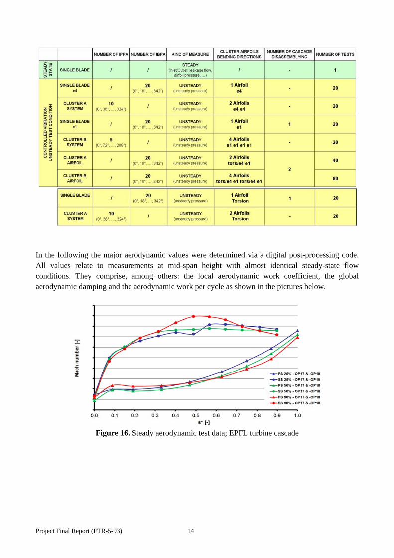
Project Final Report (FTR-5-93) 14
In the following the major aerodynamic values were determined via a digital post-processing code. All values relate to measurements at mid-span height with almost identical steady-state flow conditions. They comprise, among others: the local aerodynamic work coefficient, the global aerodynamic damping and the aerodynamic work per cycle as shown in the pictures below.
Figure 16. Steady aerodynamic test data; EPFL turbine cascade

Project Final Report (FTR-5-93) 15
Figure 17. Aeroelastic test data; EPFL turbine cascade
EPFL Compressor Experiments
This section provides the results of the tests performed in the frame of the EPFL compressor cascade controlled vibration experiment.
Figure 18. EPFL compressor test object

Project Final Report (FTR-5-93) 16
In association to the time dependant signals, steady-state flow fields and blade surface steady-state static pressures were measured. The steady-state and unsteady measurement positions are acquired at 20%, 50% and 90% of the blade span by the instrumentation shown in the picture below.
Figure 26 EPFL compressor instrumentation The operating points selected for this test campaign are based on the steady-state data acquired during the first compressor measurement campaign (October 2010). Operating points of interest has been measured with the cascade vibrating to assess unsteady data. During the unsteady measurement campaign, the cascade’s blades are subjected to controlled vibration motion (first bending mode shape). All test have been performed following the test matrix below.
Figure 27 EPFL compressor test matrix An example of results are presented below for some flow conditions. In figure 28 steady state pressure along the profile tip is presented.

Project Final Report (FTR-5-93) 17
Figure 28 EPFL compressor steady aerodynamic test data; left: blade loading, right: casing pressure Unsteady pressure measurements on the blade are presented in figure 29 per several inter-blade-phase-angle.
Figure 29 EPFL compressor aeroelastic test data

Project Final Report (FTR-5-93) 18
WP2 – LPT Rotating Rig Flutter
Introduction
Two high aspect ratio aeronautical low-pressure turbine rotor blades sharing the same aerodynamic surface were designed to flutter in a rotating high-speed wind tunnel located at the CTA (Zamudio). The first rotor blade has plane not-contacting tip-shrouds and it is referred to as the cantilever configuration whereas the second features a z-shape shroud where there is a contact with the neighbouring blades and it is named the interlock configuration.
This is the first time that a bladed-disk has been specifically designed to flutter under controlled conditions and therefore it is believed that just the proper design of test vehicle itself would justify the whole project. The major technical difficulty was to design a rotor blade within the design space of an existing rig whose vibration amplitude were high enough to be measurable but not to compromise the safe operation of the rig and the facility.
Three more experiments were designed around this test. First, and more relevant, a vacuum spinning rig was designed and built in AVIO, as a separate project, to measure the mechanical damping of both bladed-disks. The main idea is that the rotor blades are excited in a vacuum chamber by means of stationary or rotating magnet system to control separately the frequency and nodal diameter of the excitation. The pull load of the rotor blade may be controlled independently also. This is possible using two rotating disks: the specimen and a second disk that contains the magnets. The rig is complex and a number of problems had to be solved to put in operation the whole system. The main objective of this test was to determine the mechanical damping and vibration frequency of each individual blade for different shaft speeds, nodal diameters and vibration amplitudes.
A third experiment was conducted in the KTH vibrating sector cascade using the 70% span section of the airfoil to experimentally characterise the aerodynamic damping of the rotor blade under different reduced frequencies and incidences. Finally a ping test of all the rotor blades was conducted at POLITO.
Figure 19. Close-up of the Cantilever (left) and Interlocked (middle) shroud model and detail of the hardware of the interlocked rotor blade. The support for the mistuning mass can be clearly seen.
To complete the picture an experiment to validate the influence of mistuning due wearing or manufacturing imperfections on the rotor stability was designed. Rotor blade shrouds were designed

Project Final Report (FTR-5-93) 19
to host mistuning masses with the objective of testing different mistuning patterns. Two patterns were designed and tested the first adding a mass in one out of two blade with the ultimate objective of completely supress flutter and a second designed to half the vibration amplitude of the tuned bladed-disk and obtain clean signals of a mistuned fluttering configuration.
Experimental Campaign
Instrumentation. The LPT rotating rig experiment was designed to be measured with non-intrusive measurement techniques. Aerodynamic surfaces were not instrumented and therefore there is no direct measurement of the steady or unsteady pressures on the airfoils. Blade vibration measurements, both in the CTA wind tunnel and in the AVIO friction rig were performed using a blade tip timing optical system provided by RR to avoid the use of strain-gauges which are intrusive, induce an uncontrolled level of mistuning and provide incomplete information of the bladed-disk. Inlet and outlet aerodynamic boundary conditions of the rotor blade were obtained by radial and circumferential traverses of total pressure and angle using fast response five-hole probes. Inlet stagnation temperature and exit static pressure were measured also. Unsteady pressures in the casing were recorded using unsteady pressure transducers and therefore all the instrumentation used in the tests was non-intrusive.
Figure 20. CTA high speed wind-tunnel (left) and close-up of the rotor blade tip-shroud with the rotating magnets and blade tip timing optical probes (right)
Testing sequence. The cantilever bladed-disk was tested first at the CTA. The CTA wind tunnel allows an independent control of the rotor blade shaft speed, Mach and Reynolds numbers. Different shaft speeds and density levels were tested while the exit Mach number was kept constant. First low density levels and shaft speeds were tested to ensure the integrity of the hardware, once confidence was gained the different points of the test matrix were measured. Flutter could be clearly identified in a wide range of the test matrix and the experiment was considered by the consortium a great success. Then the two mistuning patterns were tested for the cantilever configuration. It could be verified that the design intent was correct and that the first pattern managed to completely supress the flutter that
Project Final Report (FTR-5-93) 20
had been intentionally created before, while the second reduced the vibration amplitude roughly to the half.
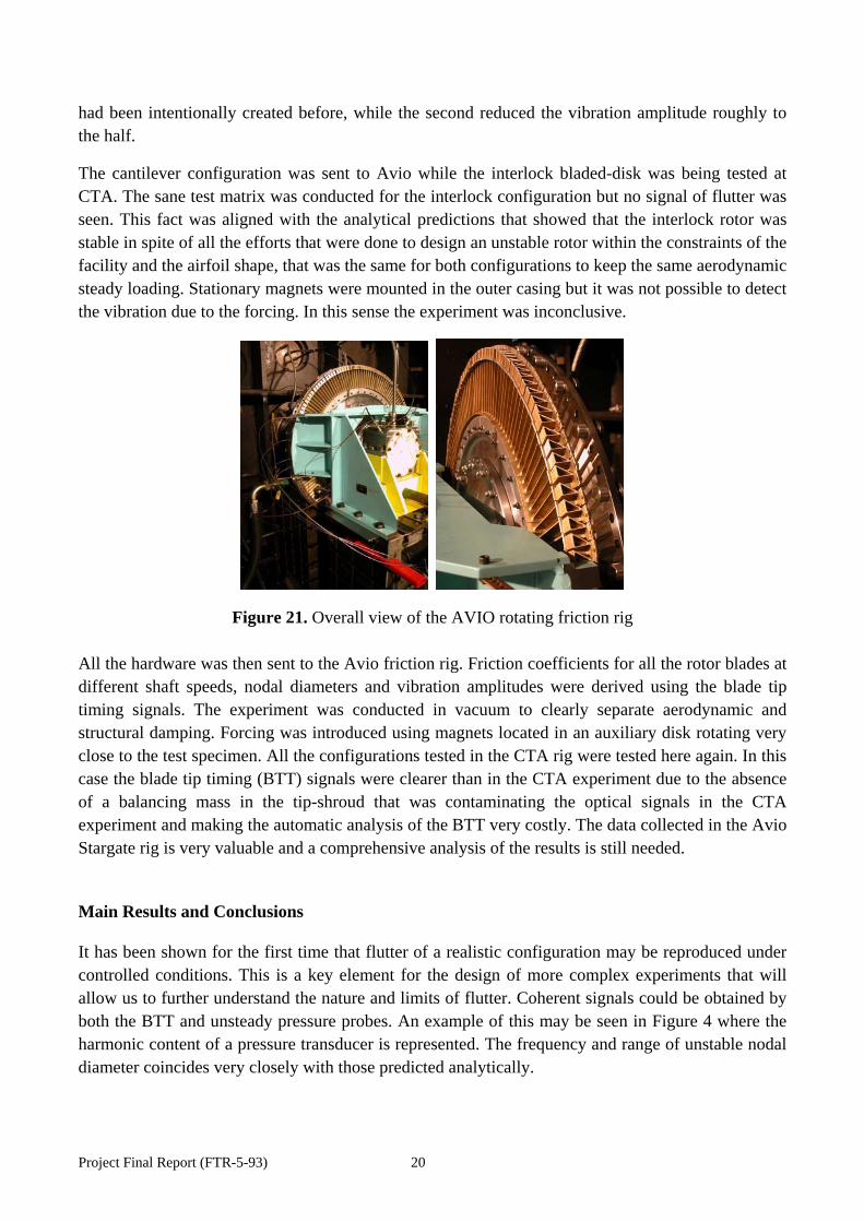
The cantilever configuration was sent to Avio while the interlock bladed-disk was being tested at CTA. The sane test matrix was conducted for the interlock configuration but no signal of flutter was seen. This fact was aligned with the analytical predictions that showed that the interlock rotor was stable in spite of all the efforts that were done to design an unstable rotor within the constraints of the facility and the airfoil shape, that was the same for both configurations to keep the same aerodynamic steady loading. Stationary magnets were mounted in the outer casing but it was not possible to detect the vibration due to the forcing. In this sense the experiment was inconclusive.
Figure 21. Overall view of the AVIO rotating friction rig All the hardware was then sent to the Avio friction rig. Friction coefficients for all the rotor blades at different shaft speeds, nodal diameters and vibration amplitudes were derived using the blade tip timing signals. The experiment was conducted in vacuum to clearly separate aerodynamic and structural damping. Forcing was introduced using magnets located in an auxiliary disk rotating very close to the test specimen. All the configurations tested in the CTA rig were tested here again. In this case the blade tip timing (BTT) signals were clearer than in the CTA experiment due to the absence of a balancing mass in the tip-shroud that was contaminating the optical signals in the CTA experiment and making the automatic analysis of the BTT very costly. The data collected in the Avio Stargate rig is very valuable and a comprehensive analysis of the results is still needed.
Main Results and Conclusions
It has been shown for the first time that flutter of a realistic configuration may be reproduced under controlled conditions. This is a key element for the design of more complex experiments that will allow us to further understand the nature and limits of flutter. Coherent signals could be obtained by both the BTT and unsteady pressure probes. An example of this may be seen in Figure 4 where the harmonic content of a pressure transducer is represented. The frequency and range of unstable nodal diameter coincides very closely with those predicted analytically.

Project Final Report (FTR-5-93) 21
It has experimentally been shown that flutter severity increases with the density level, but the trend with the shaft speed for this experiment could not be clearly explained. Further analytical work is needed fully understand this behaviour.
Figure 22. Unsteady pressure as a function of the nodal diameter and density for low shaft speeds The stabilizing effect of mistuning has been demonstrated experimentally for the first time under controlled conditions. Trends are predictable using current analytical tools but absolute values difficult to predict. The difference in the vibration amplitude of the three cases is clearly visible and the trend steady.
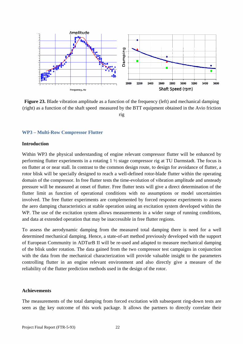
It has experimentally been shown that the vibration amplitude is controlled by non-linear mechanisms, dry friction in particular. Figure 5 (left) displays the response of the blades of the cantilever configuration as a function of the frequency. It can be clearly appreciated that the response of the rotor blade is non-symmetric about the resonance, which is the classical response of a non-linear damper. In this particular case the friction of the system is solely due to the fir-tree attachment but more complex experiments can be devised where contributions from other contacts, such as the interlock, may be expected. It has also been shown that the mechanical damping changes significantly with the shaft speed as it is outlined in Figure 5 (right). This change of the damping with the pull load needs to be properly retained in the simulation for a correct prediction of the vibration amplitude.
Project Final Report (FTR-5-93) 22
Figure 23. Blade vibration amplitude as a function of the frequency (left) and mechanical damping (right) as a function of the shaft speed measured by the BTT equipment obtained in the Avio friction
rig
WP3 – Multi-Row Compressor Flutter
Introduction
Within WP3 the physical understanding of engine relevant compressor flutter will be enhanced by performing flutter experiments in a rotating 1 ½ stage compressor rig at TU Darmstadt. The focus is on flutter at or near stall. In contrast to the common design route, to design for avoidance of flutter, a rotor blisk will be specially designed to reach a well-defined rotor-blade flutter within the operating domain of the compressor. In free flutter tests the time-evolution of vibration amplitude and unsteady pressure will be measured at onset of flutter. Free flutter tests will give a direct determination of the flutter limit as function of operational conditions with no assumptions or model uncertainties involved. The free flutter experiments are complemented by forced response experiments to assess the aero damping characteristics at stable operation using an excitation system developed within the WP. The use of the excitation system allows measurements in a wider range of running conditions, and data at extended operation that may be inaccessible in free flutter regions.
To assess the aerodynamic damping from the measured total damping there is need for a well determined mechanical damping. Hence, a state-of-art method previously developed with the support of European Community in ADTurB II will be re-used and adapted to measure mechanical damping of the blisk under rotation. The data gained from the two compressor test campaigns in conjunction with the data from the mechanical characterization will provide valuable insight to the parameters controlling flutter in an engine relevant environment and also directly give a measure of the reliability of the flutter prediction methods used in the design of the rotor.
Achievements
The measurements of the total damping from forced excitation with subsequent ring-down tests are seen as the key outcome of this work package. It allows the partners to directly correlate their

Project Final Report (FTR-5-93) 23
aeromechanical simulations on test data and to conclude on prediction accuracy of aerodynamic and mechanical damping with the additional test data from the ECL spin pit tests. Figure 24 shows the total damping as a critical damping ratio for different operating points and different nodal diameter patterns. The predicted trend of the damping versus nodal diameter as it has been shown in earlier reports agree well with test data. There are however differences that are not fully explained to date and further analysis of the data is needed here.
Figure 24. Measured total damping in the TUD compressor from blade tip timing data at various operating points
Figure 25. Free-flutter experiments in TUD compressor; operating points denoted “critical” featured higher blade vibration amplitude

Project Final Report (FTR-5-93) 24
In addition to the forced excitation experiments, the compressor operating range has been screened for free flutter occurrences. A series of operating points have been identified that featured higher vibration amplitude as depicted in Figure 25 (points denoted with “critical”). This is a substantial result as it represents a very rare test case that comes with detailed measurements of blade vibration amplitudes, accurate mechanical characterization and total damping measurements from ring-down experiments.
Figure 26. Correlation of measured and predicted damping of the TUD compressor (OP20)
Last, a comparison of measured and predicted damping is shown in Figure 26. The comparison shows that the predictions are close to test data in terms of values and trends, but that differences exist of the order of 100-200% of the measured value. This might seem as an unacceptably high value but still the order of magnitude of damping is about the same. The observed differences come to some degree from different mean aerodynamics, to some degree from the prediction of the mechanical vibration and to some degree from the varying treatment of the unsteady aerodynamics. The test data acquired during the TUD tests include also detailed measurement of the unsteady casing pressures, which is used by the partners to identify the source of the discrepancies and then to use this information to improve their aeroelastic prediction capabilities.
WP4 – Synthesis of Experiments and Computations
The work package WP4 “Synthesis of Experiments and Computations” was aimed to
do the Post-Test Predictions of Experiments o TUD compressor o EPFL Compressor cascade o CTA turbine / Star Gate Avio

Project Final Report (FTR-5-93) 25
o EPFL turbine cascade o KTH turbine cascade
Establish a database containing a set of flutter experimental data for the calibration of numerical methods
compare the measured and analytical results for all five experiments
Calibrate numerical tools for flutter and forced response predictions through direct comparisons with high-quality experimental data from all test programs in work packages 1-3, encompassing unique engine-representative configurations for turbomachinery blade instability measurements
Derive best practice guidelines o Experimental o Numerical
Elaborate improved and/or new flutter design criteria for compressors and turbines
Establishment of Data Base containing Experimental and Numerical Data
A web-based data base for the numerical and experimental data has been established at the begin of the project. According to the data standardization agreement, also elaborated within WP4, this data base has then been filled throughout the FUTURE project with the measured results from the five experiments and the corresponding analytical results from all partners. This form of communication proved to be very efficient. The resulting data base is of high value to all partners to improve their numerical methods, even after the end of the project. All deliverables, technical reports and progress reports have also been stored in the data base in a clearly laid-out and easy-accessible manner.
In addition to that, the data-base was designed such, that it could be used as a general communication platform between the partners. For that purpose each work package had a separate folder which could be structured according the needs of the involved partners. This feature was very helpful and improved the quality of the data exchange .
Post-Test Predictions / Comparison with experimental Data
TUD compressor
Goal of TUD compressor experiment and corresponding calculations was to validate aerodynamic damping of specific travelling wave modes and free flutter in a multi-stage environment.
In order to excite the blades in the travelling wave modes of interest, an excitation system (air injection system) was design within the FUTURE project and incorporated into the rig.

Project Final Report (FTR-5-93) 26
Figure 27. TUD compressor with air injector (excitation system)
A first interesting finding when comparing measured and analytical results is that the measured compressor map is relatively well captured by the calculations (Fig 4-2) even though differences in the radial flow profiles of the distinct calculations were observed, probably due to different secondary flows at the tip. This also leads to slightly different shock characteristics. (Fig 4-3).
Figure 28. Compressor map: TUD: measurement – others: calculation

Project Final Report (FTR-5-93) 27
Figure 29. Steady tip pressure field OP19: TUD picture: measurement – others: calculation
Figure 30. Flutter curve: TUD experimental results - others: calculation
Measured and calculated damping curves for one operating conditions are exemplarily depicted in Figure 4-4. There exist also cases with more variation between the various calculations and measurement. This is probably due to the different steady solutions (shock characteristics).
Free flutter could not be validated. Even though some experimental results indicated some sort of asynchronous vibrations, none of the computational results showed flutter. An exact explanation could not yet be found for the measured effect.

Project Final Report (FTR-5-93) 28
EPFL annular compressor cascade
A modern geometry 3D-rotor which is susceptible to flutter was designed within the FUTURE project for the transonic compressor rig at TU Darmstadt. A typical 2d-section of this rotor was investigated in the non-rotating annular test facility at EPFL. Due to the extensive instrumentation a better understanding of the unsteady flow was expected.
The controlled vibration experiments allow the understanding of the unsteady surface pressures for the selected cascade geometry, mode shape and frequency as a function of operating conditions, and inter-blade phase angles. Due to the non-rotating setup of the tests, the effort required to extract this information from the cascade tests is significantly lower than for the rotating rigs, so that a larger range of aerodynamic and aeroelastic parameters can be covered by the cascade tests.
Figure 31. Cavities of EPFL compressor cascade
The comparison between the experimental and numerical results showed that it is necessary to include the cavities of the EPFL compressor cascade into the CFD model in order to get the steady aerodynamic results right. This holds true for the results at inlet, outlet and blade surfaces. In the context of the FUTURE project this is extremely important, since the numerical aeroelastic results can only be correct if the steady flow field is captured correctly. In former projects numerical inlet boundary conditions had to be artificially adjusted in order to get a good agreement with measured surface pressures. Due to incorporation of the cavities within FUTURE such a non-physical modification is not necessary any more.
Project Final Report (FTR-5-93) 29
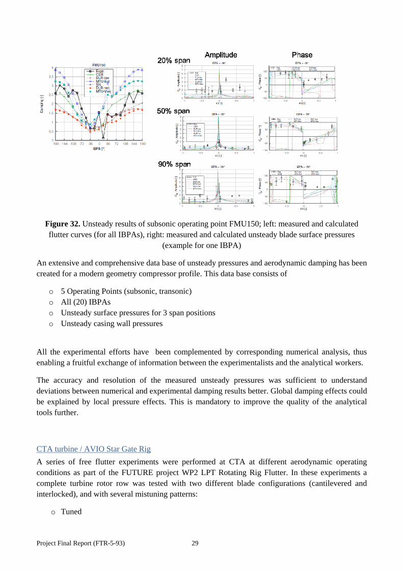
Figure 32. Unsteady results of subsonic operating point FMU150; left: measured and calculated flutter curves (for all IBPAs), right: measured and calculated unsteady blade surface pressures
(example for one IBPA)
An extensive and comprehensive data base of unsteady pressures and aerodynamic damping has been created for a modern geometry compressor profile. This data base consists of
o 5 Operating Points (subsonic, transonic) o All (20) IBPAs o Unsteady surface pressures for 3 span positions o Unsteady casing wall pressures
All the experimental efforts have been complemented by corresponding numerical analysis, thus enabling a fruitful exchange of information between the experimentalists and the analytical workers.
The accuracy and resolution of the measured unsteady pressures was sufficient to understand deviations between numerical and experimental damping results better. Global damping effects could be explained by local pressure effects. This is mandatory to improve the quality of the analytical tools further.
CTA turbine / AVIO Star Gate Rig
A series of free flutter experiments were performed at CTA at different aerodynamic operating conditions as part of the FUTURE project WP2 LPT Rotating Rig Flutter. In these experiments a complete turbine rotor row was tested with two different blade configurations (cantilevered and interlocked), and with several mistuning patterns:
o Tuned

Project Final Report (FTR-5-93) 30
o 0-1 Mistuning (alternate mistuning) o 1-1-1-1-0 Mistuning (4 equal blades, 1 distinct)
The blade oscillations have been measured with a optical tip-timing system. Additionally unsteady hub wall pressures have been measured.
The mechanical damping of the rotor configuration was measured in a very sophisticated manner under rotation with a co-rotating magnetic excitation system in the vacuum at the AVIO rig.
The rotor was designed within the FUTURE project such that it should flutter in its tuned, cantilevered configuration at certain operating conditions and to be stable in the cantilevered, alternate mistuning configuration.
WP4 of the FUTURE project includes the realization of the post-test numerical computations (modal analysis, steady aerodynamics, and unsteady aerodynamics) required to reproduce the aeroelastic and dynamical behavior of the CTA experiment and AVIO experiment.
One major success in terms of validation was that for the cantilevered configuration
o In the tuned case both, the CTA experiment as well as the numerical results showed aerodynamic instabilities (flutter, limit-cycle oscillations)
o In the alternate mistuning case both, the CTA experiment as well as the numerical results showed aerodynamic stable behavior
o In the 1-1-1-1-0 mistuning case both, the CTA experiment as well as the numerical results showed approximately have the instability of the tuned case
Figure 33. Left: basic sector for the alternate mistuning calculations. Right: Mistuning mass (blue).
Another very interesting finding is that in case of aerodynamic instabilities (flutter, limit cyclice oscillation) several nodal diameters (or inter blade phase angles) can become unstable at the same time. In case of the experimental results this could be seen nicely in the unsteady hub pressure signal

Project Final Report (FTR-5-93) 31
(see. Fig 4-8) since in the steady frame of reference (probe system) each nodal diameter corresponds to a different frequency, while in the rotor frame of reference the frequencies are almost identical. The analytical results of all partners (see Fig 4-9) all show a wide range of unstable nodal diameters (negative critical damping values), too.
Figure 34. Frequency spectrum of the unsteady pressure measurements from the CTA rig for the case OP1. The nodal diameters are indicated with red lines. The most unstable one corresponds to ND=-21, and the range of NDs present in the spectrum goes approximately from ND=-18 to ND=-
31.
Figure 35. OP1, first modal family, critical damping ratio vs. nodal diameter, with the STARGATE measurements included. Dashed and solid vertical blue lines mark the range of unstable ND, and the
most unstable ND, from the CTA measurements.

Project Final Report (FTR-5-93) 32
In Figure 4-9 in addition the comparison of the numerical damping results to the measured mechanical damping from the star gate rig is shown: In case of the (measured) limit cycle oscillation the mechanical damping (black squares) is expected to equal the aerodynamic instability.
KTH turbine cascade
The KTH non-rotating turbine cascade comprises an annular sector of five blades one of which was made oscillating in controlled rigid-body modes. The unsteady pressure was measured during controlled blade oscillation on the oscillating blade itself and on two neighbour blades. The testing of the aeroelastic properties was hence done in the influence coefficient domain. Data were acquired at nominal operating conditions and severe off-design condition such as to force induce a massive separation on the pressure side. The intent was to assess the effect of this separation on the unsteady behaviour of the flow during blade oscillation. The figures below shows a sample comparison of the measured and predicted steady and unsteady pressure on the oscillating blade.
Figure 36. Comparison of test data and simulation results at operating point OP3; left: steady loading, right: unsteady loading
EPFL annular turbine cascade
The EPFL non-rotating annular turbine cascade comprises 20 oscillating blades, each one controlled by an independent excitation system. Three different experimental campaigns were conducted, for a total of nine distinct controlled vibration tests. The EPFL annular turbine tests served especially to validate the analytical prediction of the flutter behavior of packages of vanes or blades. In case of vane rows this is important since LPT vanes are often assembled out of vane clusters. In case of blades there exist concepts to have welded pairs of blades. The oscillating behavior and aeroelastic behavior of a cluster differs from that of a single vane or blade. In the EPFL annular turbine cascade such cluster modes have been excited in a controlled manner and unsteady pressures could be
Project Final Report (FTR-5-93) 33
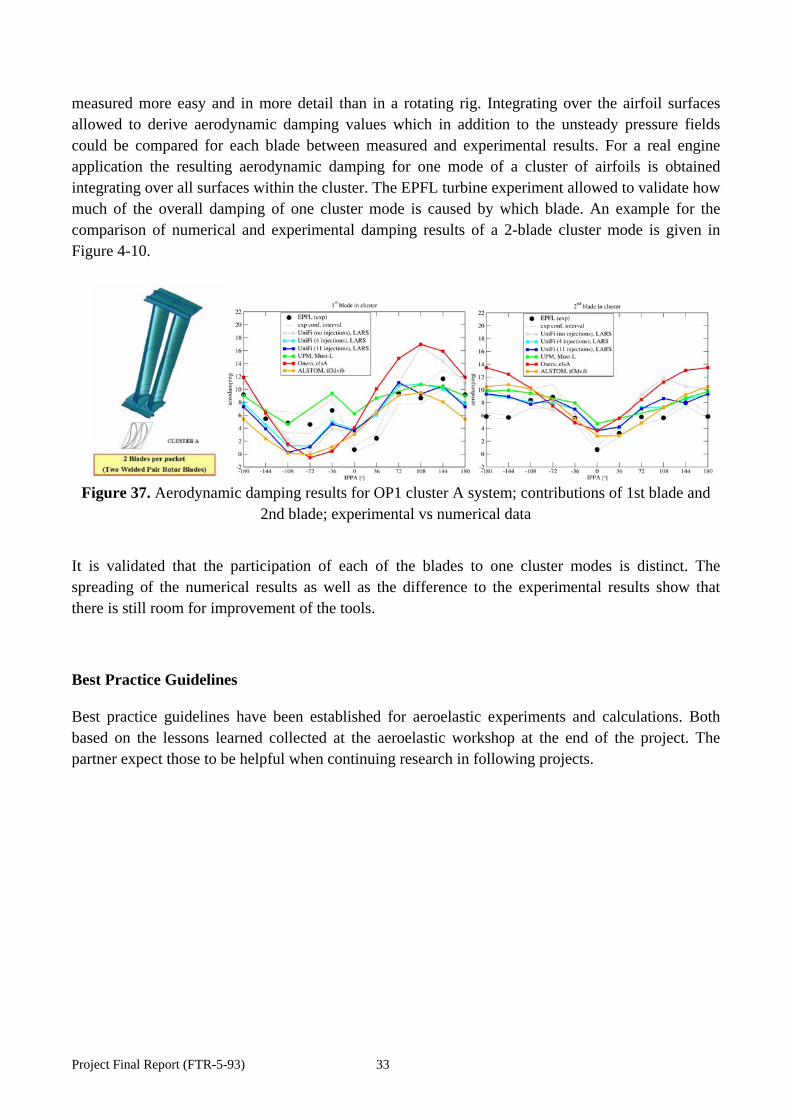
measured more easy and in more detail than in a rotating rig. Integrating over the airfoil surfaces allowed to derive aerodynamic damping values which in addition to the unsteady pressure fields could be compared for each blade between measured and experimental results. For a real engine application the resulting aerodynamic damping for one mode of a cluster of airfoils is obtained integrating over all surfaces within the cluster. The EPFL turbine experiment allowed to validate how much of the overall damping of one cluster mode is caused by which blade. An example for the comparison of numerical and experimental damping results of a 2-blade cluster mode is given in Figure 4-10.
Figure 37. Aerodynamic damping results for OP1 cluster A system; contributions of 1st blade and
2nd blade; experimental vs numerical data
It is validated that the participation of each of the blades to one cluster modes is distinct. The spreading of the numerical results as well as the difference to the experimental results show that there is still room for improvement of the tools.
Best Practice Guidelines
Best practice guidelines have been established for aeroelastic experiments and calculations. Both based on the lessons learned collected at the aeroelastic workshop at the end of the project. The partner expect those to be helpful when continuing research in following projects.

Project Final Report (FTR-5-93) 34
3. Dissemination activities
Publications
Title Author(s) Lead author affiliation
Conference Journal
Year Type1
An Excitation System for Fan Blade Flutter Experimentation
Snedden, G., Wegman, E., van Zyl, L., Dunn, D., Grobler, J.-H.
CSIR IASSA Symposium
2010 PR
The Development of an Air Injection System for the Forced Response Testing of Axial Compressors
Wegman, E., Snedden, G., Van der Spuy, J., Holzinger, F., Schiffer, H.-P., Mårtensson, H., Östlund J.
CSIR ASME Turbo Expo GT2013-96011
2013 CP
Experimental Aeroelastic Analysis of Clustered Turbine Blades Vibrating in Mixed Torsion/Bending Mode
Zanker, A., Ott, P., Calza, P.
EPFL AIAA Symposium
2013 CP
Experimental Aeroelastic Investigation of Vibrating Turbine Blade Clusters
Zanker, A., Ott, P., Calza, P.
EPFL ETC conference
2013 CP
Transonic Compressor Flutter Research within the FUTURE Project
Mårtensson, H., Östlund, J.
GKN (VAC)
CEAS Conference
2013 CP
Design and Analysis of a Transonic Flutter Research Compressor
Mårtensson, H., Östlund, J., Bladh, R., Grüber, B.
VAC (GKN)
IFASD conference
2011 CP
Design and Pre-Test Analyses of the Transonic Flutter Research Compressor for FUTURE
Mårtensson, H., Östlund, J., Bladh, R.,
VAC (GKN)
ISUAAAT conference
2012 CP
Aerodynamic Coupling Effects on Intentionally Mistuned Bladed Disks
Sotillo, A., Khemiri, O., Martel, C.,
ITP ASME Turbo Expo
2014 CA
1JP: journal paper, CP: conference paper, PR: presentation, CA: abstract of conference paper, IL: invited lecture
Project Final Report (FTR-5-93) 35
Corral, R. Towards Flutter-Free Turbomachinery Blades
Vogt, D.M., Fransson, T.H.
KTH Aero Days 2011 CP
Turbomachinery Aeroelasticity Analyses - Everyday Business or Exceptional Challenge?
Vogt, D.M., Fransson, T.H.
KTH ETC conference
2011 IL
Current Research on Turbomachinery Flutter within the EU Collaborative Project “FUTURE”
Vogt, D.M. KTH ISUAAAT conference
2012 IL
Development of an Excitation System for Forced Response Investigations in the TU Darmstadt Compressor
Holzinger, F., Biela, C., Schiffer, H.-P., Östlund, J., Mårtensson, H.
TUD ISUAAAT conference
2009 CP
Commissioning the FUTURE Compressor
Holzinger, F., Leichtfuß, S., Schiffer, H.-P., Östlund, J., Kharyton, V.
TUD ISUAAAT conference
2012 CP
Student theses (MSc theses, diploma works, term theses)
Title Author Supervised by Partner
Performed at Partner
Year Type
Development of a Concept for Forced Response Investigations
Felix Holzinger
TUD VAC (GKN)
2009 MSc
Konstruktion eines Gehäuses für einen 1 ½-stufigen Axialverdichter mit Vorleiträdern, Schleifring- und Anregungssystem Design of a casing for a 1 ½ stage axial compressor with inlet guide vanes, slip ring and excitation system
Sebastian Bürkle
TUD TUD 2010 BSc
Development of a Model for Designing Flexibly Deforming Turbine Blades for Testing Purpose
Omid Lorestani
KTH KTH 2010 MSc
Experimentelle Untersuchung von Drucklufteinblasung am Kalibrationskanal
Felix Stritzke TUD TUD 2010 BSc

Project Final Report (FTR-5-93) 36
Experimental Investigation of Compressed Air Injection at the Calibration Rig Echtzeitmessung des Schaufelspitzenspalts in einem transsonischen Verdichter Real-time measurement of the blade tip clearance in a transonic compressor
Bayan Luantonio Morocho Mondavi
TUD TUD 2011 BSc
Inbetriebnahme eines verstellbaren Vorleitrades für einen Transsonischen Verdichter Commissioning of Variable Inlet Guide Vanes for a Transonic Compressor
Muhanad Mahmoud Hassan Ahmed
TUD TUD 2011 BSc
Vibration excitation of axial compressor rotor blades
Gert Raubenheimer
SUN SUN 2011 MSc
Studio dei fenomeni aeroelastici nelle palettature di turbine a gas con metodi numerici
David Disabato
UniFi UniFi 2012 PhD
Instationäre Auswertung von Daten einer transsonischen Verdichterstufe Unsteady Analysis of Data of a Transonic Compressor Stage
Tim Hauser TUD TUD 2012 BSc
Mistuning and Damping Characterizations of a Turbine Rotor for Flutter Investigation
Mauricio Gutierrez
KTH GKN (VA) 2012 MSc
Validation and Verification of Flutter CFD Tools for Steam Turbines with Cascade Measurements
Stefano Cerutti KTH Alstom 2012 MSc
Kennfeldauswertung einer Transsonikverdichterstufe Performance assessment of a transonic compressor stage
Fabian von Blücher
TUD TUD 2013 BSc
Schaufelschwingungsanalyse eines Transsonikverdichters mit Hilfe von Spaltweitensensoren Tip clearance probe based blade vibration study on a transonic compressor
Timo Graeber TUD TUD 2013 BSc
Aerodynamic and Aeroelastic Francesco UniFi GKN 2013 MSc

Project Final Report (FTR-5-93) 37
Analysis of a Transonic Research Compressor
Troiano
Assessment of two Commercial Software Packages for the Prediction of Flutter in Gas Turbine
Milad Mosalman
KTH KTH 2013 MSc
Assessment of Non-Proprietary Codes for Flutter Prediction in a Compressor Stage
Vikram Reddy KTH KTH 2013 MSc
Validation of Detailed CFD Simulation of Cascade Flutter
Milos Ivankovic
KTH IC 2012 MSc

Project Final Report (FTR-5-93) 38
4. Address of the project public website
www.future-project.eu
5. Additional material
Project logo
Photos of project consortium
Figure 38. Meeting at DLR in Göttingen, May 2012

Project Final Report (FTR-5-93) 39
Figure 39. Meeting at UPM/ITP in Madrid, Nov 2011
Figure 40. Meeting at KTH in Stockholm, June 2013

Project Final Report (FTR-5-93) 40
Active project participants (status at end of project)
Damian Vogt KTH Ronnie Bladh Siemens
Torsten Fransson KTH Vsevolod Kharyton Siemens
Antonio Sanz KTH Ivan McBean Alstom
Paolo Calza AVIO Francesco Poli UniFi
Carlos Martel UPM Daniele Botto Polito
Roque Corral ITP Glen Snedden CSIR
Almudena Vega Cosa UPM Johan van der Spuy SUN
Peter Ott EPFL Detlef Korte MTU
Achim Zanker EPFL Felix Holzinger TUD
Bob Elliott RR Virginie Chenaux DLR
Gilles Leroy Turbomeca Joachim Belz DLR
Renaud Daon Snecma Frédéric Sicot Cerfacs
Arnaud Naert TA Laurent Blanc ECL
Marie-Claire Merienne Onera Luca di Mare IC
Jan Östlund GKN (VA) Robin Elder PCA
Eric Wegman CSIR Maria Mayorca Siemens
Laurent Blanc ECL Arrigo Beretta RR
Hans Mårtensson VA (GKN) Pieter Groth VA (GKN)

Project Final Report (FTR-5-93) 41
4.1 Report on societal implications
Replies to the following questions will assist the Commission to obtain statistics and indicators on societal and socio-economic issues addressed by projects. The questions are arranged in a number of key themes. As well as producing certain statistics, the replies will also help identify those projects that have shown a real engagement with wider societal issues, and thereby identify interesting approaches to these issues and best practices. The replies for individual projects will not be made public.
A General Information (completed automatically when Grant Agreement number is
entered. Grant Agreement Number: 213414
Title of Project: FUTURE – Flutter-Free Turbomachinery Blades
Name and Title of Coordinator: Prof. Torsten Fransson
B Ethics
1. Did your project undergo an Ethics Review (and/or Screening)?
If Yes: have you described the progress of compliance with the relevant Ethics Review/Screening Requirements in the frame of the periodic/final project reports?
Special Reminder: the progress of compliance with the Ethics Review/Screening Requirements should be described in the Period/Final Project Reports under the Section 3.2.2 'Work Progress and Achievements'
No
2. Please indicate whether your project involved any of the following issues (tick box) :
YES
RESEARCH ON HUMANS
Did the project involve children?
Did the project involve patients?
Did the project involve persons not able to give consent?
Did the project involve adult healthy volunteers?
Did the project involve Human genetic material?
Did the project involve Human biological samples?
Did the project involve Human data collection?
RESEARCH ON HUMAN EMBRYO/FOETUS
Did the project involve Human Embryos?
Did the project involve Human Foetal Tissue / Cells?
Did the project involve Human Embryonic Stem Cells (hESCs)?
Did the project on human Embryonic Stem Cells involve cells in culture?
Did the project on human Embryonic Stem Cells involve the derivation of cells from Embryos?
PRIVACY
Did the project involve processing of genetic information or personal data (eg. health, sexual

Project Final Report (FTR-5-93) 42
lifestyle, ethnicity, political opinion, religious or philosophical conviction)?
Did the project involve tracking the location or observation of people?
RESEARCH ON ANIMALS
Did the project involve research on animals?
Were those animals transgenic small laboratory animals?
Were those animals transgenic farm animals?
Were those animals cloned farm animals?
Were those animals non-human primates?
RESEARCH INVOLVING DEVELOPING COUNTRIES
Did the project involve the use of local resources (genetic, animal, plant etc)?
Was the project of benefit to local community (capacity building, access to healthcare, education etc)?
DUAL USE
Research having direct military use 0 Yes 0 No
Research having the potential for terrorist abuse
C Workforce Statistics
3. Workforce statistics for the project: Please indicate in the table below the number of people who worked on the project (on a headcount basis).
Type of Position Number of Women Number of Men
Scientific Coordinator 0 1
Work package leaders 1 5 Experienced researchers (i.e. PhD holders) 3 25 PhD Students 2 10 Other 6 22
4. How many additional researchers (in companies and universities) were recruited specifically for this project?
12
Of which, indicate the number of men:
10

Project Final Report (FTR-5-93) 43
D Gender Aspects
5. Did you carry out specific Gender Equality Actions under the project?
x
Yes No
6. Which of the following actions did you carry out and how effective were they?
Not at all effective
Very effective
x Design and implement an equal opportunity policy X Set targets to achieve a gender balance in the workforce Organise conferences and workshops on gender x Actions to improve work-life balance X Other:
7. Was there a gender dimension associated with the research content – i.e. wherever people were
the focus of the research as, for example, consumers, users, patients or in trials, was the issue of gender considered and addressed?
Yes- please specify
X No
E Synergies with Science Education
8. Did your project involve working with students and/or school pupils (e.g. open days, participation in science festivals and events, prizes/competitions or joint projects)?
x Yes- please specify : education of students at involved universities, MSc student at industry partners
No
9. Did the project generate any science education material (e.g. kits, websites, explanatory booklets, DVDs)?
x Yes- please specify : learning material at universities
No
F Interdisciplinarity
10. Which disciplines (see list below) are involved in your project?
x Main discipline2: 2.3
Associated discipline2: Associated discipline2:
G Engaging with Civil society and policy makers
11a Did your project engage with societal actors beyond the research community? (if 'No', go to Question 14)
x
Yes No
2 Insert number from list below (Frascati Manual).

Project Final Report (FTR-5-93) 44
11b If yes, did you engage with citizens (citizens' panels / juries) or organised civil society (NGOs, patients' groups etc.)?
No
Yes- in determining what research should be performed
Yes - in implementing the research
Yes, in communicating /disseminating / using the results of the project
11c In doing so, did your project involve actors whose role is mainly to organise the dialogue with citizens and organised civil society (e.g. professional mediator; communication company, science museums)?
Yes No
12. Did you engage with government / public bodies or policy makers (including international organisations)
No
Yes- in framing the research agenda
Yes - in implementing the research agenda
Yes, in communicating /disseminating / using the results of the project
13a Will the project generate outputs (expertise or scientific advice) which could be used by policy makers?
Yes – as a primary objective (please indicate areas below- multiple answers possible)
Yes – as a secondary objective (please indicate areas below - multiple answer possible)
No
13b If Yes, in which fields? Agriculture Audiovisual and Media Budget Competition Consumers Culture Customs Development Economic and Monetary Affairs Education, Training, Youth Employment and Social Affairs
Energy Enlargement Enterprise Environment External Relations External Trade Fisheries and Maritime Affairs Food Safety Foreign and Security Policy Fraud Humanitarian aid
Human rights Information Society Institutional affairs Internal Market Justice, freedom and security Public Health Regional Policy Research and Innovation Space Taxation Transport

Project Final Report (FTR-5-93) 45
13c If Yes, at which level?
Local / regional levels
National level
European level
International level
H Use and dissemination
14. How many Articles were published/accepted for publication in peer-reviewed journals?
0
To how many of these is open access3 provided? -
How many of these are published in open access journals? -
How many of these are published in open repositories? -
To how many of these is open access not provided? -
Please check all applicable reasons for not providing open access: -
publisher's licensing agreement would not permit publishing in a repository no suitable repository available no suitable open access journal available no funds available to publish in an open access journal lack of time and resources lack of information on open access other4: ……………
-
15. How many new patent applications (‘priority filings’) have been made? ("Technologically unique": multiple applications for the same invention in different jurisdictions should be counted as just one application of grant).
0
16. Indicate how many of the following Intellectual Property Rights were applied for (give number in each box).
Trademark -
Registered design -
Other -
17. How many spin-off companies were created / are planned as a direct result of the project?
0
Indicate the approximate number of additional jobs in these companies: -
18. Please indicate whether your project has a potential impact on employment, in comparison with the situation before your project:
Increase in employment, or x In small & medium-sized enterprises
x Safeguard employment, or x In large companies
Decrease in employment, None of the above / not relevant to the project
3 Open Access is defined as free of charge access for anyone via Internet. 4 For instance: classification for security project.

Project Final Report (FTR-5-93) 46
Difficult to estimate / not possible to quantify
19. For your project partnership please estimate the employment effect resulting directly from your participation in Full Time Equivalent (FTE =
one person working fulltime for a year) jobs: Difficult to estimate / not possible to quantify
Indicate figure: X
I Media and Communication to the general public
20. As part of the project, were any of the beneficiaries professionals in communication or media relations?
Yes x No
21. As part of the project, have any beneficiaries received professional media / communication training / advice to improve communication with the general public?
Yes x No
22 Which of the following have been used to communicate information about your project to the general public, or have resulted from your project?
Press Release Coverage in specialist press
Media briefing Coverage in general (non-specialist) press
TV coverage / report Coverage in national press
Radio coverage / report Coverage in international press
Brochures /posters / flyers x Website for the general public / internet
DVD /Film /Multimedia x Event targeting general public (festival, conference, exhibition, science café)
23 In which languages are the information products for the general public produced?
Language of the coordinator x English
Other language(s)
Question F-10: Classification of Scientific Disciplines according to the Frascati Manual 2002 (Proposed Standard Practice for Surveys on Research and Experimental Development, OECD 2002):
FIELDS OF SCIENCE AND TECHNOLOGY 1. NATURAL SCIENCES 1.1 Mathematics and computer sciences [mathematics and other allied fields: computer sciences and other
allied subjects (software development only; hardware development should be classified in the engineering fields)]
1.2 Physical sciences (astronomy and space sciences, physics and other allied subjects) 1.3 Chemical sciences (chemistry, other allied subjects)

Project Final Report (FTR-5-93) 47
1.4 Earth and related environmental sciences (geology, geophysics, mineralogy, physical geography and other geosciences, meteorology and other atmospheric sciences including climatic research, oceanography, vulcanology, palaeoecology, other allied sciences)
1.5 Biological sciences (biology, botany, bacteriology, microbiology, zoology, entomology, genetics, biochemistry, biophysics, other allied sciences, excluding clinical and veterinary sciences)
2 ENGINEERING AND TECHNOLOGY 2.1 Civil engineering (architecture engineering, building science and engineering, construction engineering,
municipal and structural engineering and other allied subjects) 2.2 Electrical engineering, electronics [electrical engineering, electronics, communication engineering and
systems, computer engineering (hardware only) and other allied subjects] 2.3. Other engineering sciences (such as chemical, aeronautical and space, mechanical, metallurgical and
materials engineering, and their specialised subdivisions; forest products; applied sciences such as geodesy, industrial chemistry, etc.; the science and technology of food production; specialised technologies of interdisciplinary fields, e.g. systems analysis, metallurgy, mining, textile technology and other applied subjects)
3. MEDICAL SCIENCES 3.1 Basic medicine (anatomy, cytology, physiology, genetics, pharmacy, pharmacology, toxicology,
immunology and immunohaematology, clinical chemistry, clinical microbiology, pathology) 3.2 Clinical medicine (anaesthesiology, paediatrics, obstetrics and gynaecology, internal medicine, surgery,
dentistry, neurology, psychiatry, radiology, therapeutics, otorhinolaryngology, ophthalmology) 3.3 Health sciences (public health services, social medicine, hygiene, nursing, epidemiology) 4. AGRICULTURAL SCIENCES 4.1 Agriculture, forestry, fisheries and allied sciences (agronomy, animal husbandry, fisheries, forestry,
horticulture, other allied subjects) 4.2 Veterinary medicine 5. SOCIAL SCIENCES 5.1 Psychology 5.2 Economics 5.3 Educational sciences (education and training and other allied subjects) 5.4 Other social sciences [anthropology (social and cultural) and ethnology, demography, geography
(human, economic and social), town and country planning, management, law, linguistics, political sciences, sociology, organisation and methods, miscellaneous social sciences and interdisciplinary , methodological and historical S1T activities relating to subjects in this group. Physical anthropology, physical geography and psychophysiology should normally be classified with the natural sciences].
6. HUMANITIES 6.1 History (history, prehistory and history, together with auxiliary historical disciplines such as
archaeology, numismatics, palaeography, genealogy, etc.) 6.2 Languages and literature (ancient and modern) 6.3 Other humanities [philosophy (including the history of science and technology) arts, history of art, art
criticism, painting, sculpture, musicology, dramatic art excluding artistic "research" of any kind, religion, theology, other fields and subjects pertaining to the humanities, methodological, historical and other S1T activities relating to the subjects in this group]

Project Final Report (FTR-5-93) 48
2. FINAL REPORT ON THE DISTRIBUTION OF THE EUROPEAN UNION FINANCIAL CONTRIBUTION
Please refer to the numbers reported in the FORCE database.