project 019-271 sd highway 19 turner county 1 · 2015-04-24 · 0.581 turner county sd highway 19...
TRANSCRIPT
STATE OF SOUTH DAKOTA
DEPARTMENT OF TRANSPORTATION
PLANS FOR PROPOSEDINDEX OF SHEETS
DAKOTA
SOUTH
OF
STATE PROJECT SHEETSHEETS
TOTAL
04/24/2015Plotting Date:
tr
mi1nt15
1:5600
1
Plotted
Fro
m -
Plot
Scale -
File - ...\turnI3
QP\
TitlI3
QP.dgn
Plot
Na
me -
GREGORY
MIX
CHARLES
BUFFALO
KINGSBURYBROOKINGS
JERAULD SANBORN MINER LAKE MOODY
MINNEHAHAMcCOOKHANSONDAVISON
AURORABRULE
DOUGLASLINCOLN
TURNER
HUTCHINSON
BON
HOMME
YANKTONCLAY UNION
LAWRENCE
BUTTE
HARDINGPERKINS CORSON
MEADE
PENNINGTON
CUSTER
FALL RIVER
CAMPBELL McPHERSON BROWN MARSHALL ROBERTS
ZIEBACH DEWEY
WALWORTH
POTTER
SULLY
EDMUNDS
FAULK
HYDE HAND
SPINK
DAY
GRANT
CODINGTONCLARK
DEUEL
HAMLIN
BENNETT
JACKSON
HAAKON
STANLEY
TODD
MELLETTE
BEADLE
JONES
TRIPP
HUGHES
LYMAN
PROJECT
STORM WATER PERMIT
(None required)
19
44
131415
1110
123
363534
2627
2423
16 5 4
12
13
36
25
19
30
31
20
29
32
21
33
S. D.
452
AV
E
POP. 1,022
D2
2
C4
Camp
Creek
Elce
Creek
44
19
455
AV
E
456
AV
E
457
AV
E
458
AV
E
R 53 W
T 9
9 N
T 1
00 N
PARKER
273 ST
274 ST
276 ST
272 ST
271 ST
275 ST
453
AV
E
East
Fork
Vermillion
River
River
VermillionFork
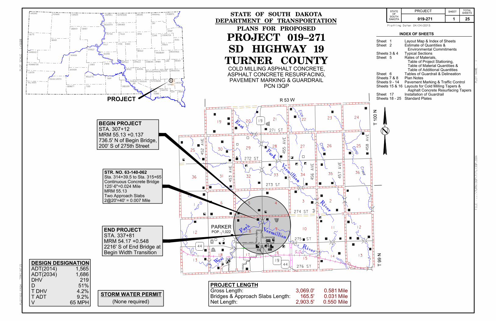
STR. NO. 63-140-062
2@20’=40’ = 0.007 Mile
Two Approach Slabs
MRM 55.13
125’-6"=0.024 Mile
Continuous Concrete Bridge
Sta. 314+39.5 to Sta. 315+65
END PROJECT
Begin Width Transition
2216’ S of End Bridge at
MRM 54.17 +0.548
STA. 337+81
BEGIN PROJECT
200’ S of 275th Street
736.5’ N of Begin Bridge,
MRM 55.13 +0.137
STA. 307+12
22
28 25
129
87
161718
DESIGN DESIGNATION
V
T ADT
T DHV
D
DHV
ADT(2034)
ADT(2014)
65 MPH
9.2%
4.2%
51%
219
1,686
1,565
PROJECT LENGTH
Net Length:
Bridges & Approach Slabs Length:
Gross Length:
2,903.5’
165.5’
3,069.0’
Mile
Mile
Mile
0.550
0.031
0.581
TURNER COUNTY
SD HIGHWAY 19
PROJECT 019-271
PCN I3QP
PAVEMENT MARKING & GUARDRAIL
ASPHALT CONCRETE RESURFACING,
COLD MILLING ASPHALT CONCRETE,
West
OGLALA LAKOTA
Standard Plates
Installation of Guardrail
Asphalt Concrete Resurfacing Tapers
Layouts for Cold Milling Tapers &
Pavement Marking & Traffic Control
Plan Notes
Tables of Guardrail & Delineation
Table of Additional Quantities
Table of Material Quantities &
Table of Project Stationing,
Rates of Materials,
Typical Sections
Environmental Commitments
Estimate of Quantities &
Layout Map & Index of Sheets
Sheets 18 - 25
Sheet 17
Sheets 15 & 16
Sheets 9 - 14
Sheets 7 & 8
Sheet 6
Sheet 5
Sheets 3 & 4
Sheet 2
Sheet 1
019-271 1 25

ESTIMATE OF QUANTITIES & ENVIRONMENTAL COMMITMENTS
PROJECT
STATE OF
SOUTH DAKOTA __ ____(__)___
SHEET
__ __
TOTAL SHEETS
ESTIMATE OF QUANTITIES
SPECIFICATIONS Standard Specifications for Roads and Bridges, 2004 Edition and Required Provisions, Supplemental Specifications and Special Provisions as included in the Proposal. ENVIRONMENTAL COMMITMENTS An Environmental Commitment is a measure that SDDOT commits to implement in order to avoid, minimize, and/or mitigate a real or potential environmental impact. Environmental commitments to various agencies and the public have been made to secure approval of this project. An agency mentioned below with permitting authority can influence a project if perceived environmental impacts have not been adequately addressed. Unless otherwise designated, the Contractor’s primary contact regarding matters associated with these commitments will be the Project Engineer. These environmental commitments are not subject to change without prior written approval from the SDDOT Environmental Office. The environmental commitments associated with this project are as follows: COMMITMENT B: FEDERALLY THREATENED, ENDANGERED, AND PROTECTED SPECIES COMMITMENT B2: WHOOPING CRANE The Whooping Crane is a spring and fall migratory bird in South Dakota that is about 5 feet tall and typically stops on wetlands, rivers, and agricultural lands along their migration route. An adult Whooping Crane is white with a red crown and a long, dark, pointed bill. Immature Whooping Cranes are cinnamon brown. While in flight, their long necks are kept straight and their long dark legs trail behind. Adult Whooping Cranes' black wing tips are visible during flight. Action Taken/Required: Harassment or other measures to cause the Whooping Crane to leave the site is a violation of the Endangered Species Act. If a Whooping Crane is sighted roosting in the vicinity of the project, borrow pit, or staging site associated with the project, cease construction activities in the affected area until the Whooping Crane departs and contact the Project Engineer. The Project Engineer will contact the Environmental Office so that the sighting can be reported to USFWS.
COMMITMENT C: WATER SOURCE The Contractor shall not withdraw water with equipment previously used outside the State of South Dakota without prior approval from the SDDOT Environmental Office. Thoroughly wash all construction equipment before entering South Dakota to reduce the risk of invasive species introduction into the project vicinity. The Contractor shall not withdraw water directly from streams of the James, Big Sioux, and Vermillion watersheds without prior approval from the SDDOT Environmental Office. Action Taken/Required: The Contractor shall obtain the necessary permits from the regulatory agencies such as the Department of Environment and Natural Resources (DENR) and the United States Army Corps of Engineers (COE) prior to executing water extraction activities. COMMITMENT E: STORM WATER Construction activities constitute less than 1 acre of disturbance. Action Taken/Required: At a minimum and regardless of project size, appropriate erosion and sediment control measures must be installed to control the discharge of pollutants from the construction site. COMMITMENT H: WASTE DISPOSAL SITE The Contractor shall furnish a site(s) for the disposal of construction and/or demolition debris generated by this project. Action Taken/Required: Construction and/or demolition debris may not be disposed of within the State ROW. The waste disposal site(s) shall be managed and reclaimed in accordance with the following from the General Permit for Highway, Road, and Railway Construction/Demolition Debris Disposal Under the South Dakota Waste Management Program issued by the Department of Environment and Natural Resources. The waste disposal site(s) shall not be located in a wetland, within 200 feet of surface water, or in an area that adversely affects wildlife, recreation, aesthetic value of an area, or any threatened or endangered species, as approved by the Project Engineer. If the waste disposal site(s) is located such that it is within view of any ROW, the following additional requirements shall apply: 1. Construction and/or demolition debris consisting of concrete, asphalt
concrete, or other similar materials shall be buried in a trench completely separate from wood debris. The final cover over the construction and/or demolition debris shall consist of a minimum of 1 foot of soil capable of supporting vegetation. Waste disposal sites provided outside of the State ROW shall be seeded in accordance with Natural Resources Conservation Service recommendations. The seeding recommendations may be obtained through the appropriate County NRCS Office. The Contractor shall control the access to waste disposal sites not within the State ROW through the use of fences, gates, and placement of a sign or signs at the entrance to the site stating No Dumping Allowed.
2. Concrete and asphalt concrete debris may be stockpiled within view of
the ROW for a period of time not to exceed the duration of the project. Prior to project completion, the waste shall be removed from view of the ROW or buried and the waste disposal site reclaimed as noted above.
COMMITMENT H: WASTE DISPOSAL SITE (CONTINUED) The above requirements will not apply to waste disposal sites that are covered by an individual solid waste permit as specified in SDCL 34A-6-58, SDCL 34A-6-1.13, and ARSD 74:27:10:06. Failure to comply with the requirements stated above may result in civil penalties in accordance with South Dakota Solid Waste Law, SDCL 34A-6-1.31. Cost associated with furnishing waste disposal site(s), disposing of waste, maintaining control of access (fence, gates and signs), and reclamation of the waste disposal site(s) shall be incidental to the contract unit prices for the various items. COMMITMENT I: HISTORICAL PRESERVATION OFFICE CLEARANCES The SDDOT has obtained concurrence with the State Historical Preservation Office (SHPO or THPO) for all work included within the project limits and all designated option borrow sites provided within the plans. Action Taken/Required: All earth disturbing activities not designated within the plans require review of cultural resources impacts. This work includes, but is not limited to: staging areas, borrow sites, waste disposal sites, and all material processing sites. The Contractor shall arrange and pay for a cultural resource survey and/or records search. The Contractor has the option to contact the state Archaeological Research Center (ARC) at 605-394-1936 or another qualified archaeologist, to obtain either a records search or a cultural resources survey. A record search might be sufficient for review; however, a cultural resources survey may need to be conducted by a qualified archaeologist. The Contractor shall provide ARC with the following: a topographical map or aerial view on which the site is clearly outlined, site dimensions, project number, and PCN. If applicable, provide evidence that the site has been previously disturbed by farming, mining, or construction activities with a landowner statement that artifacts have not been found on the site. The Contractor shall submit the records search or cultural resources survey report and if the location of the site is within the current geographical or historic boundaries of any South Dakota reservation to SDDOT Environmental Engineer, 700 East Broadway Avenue, Pierre, SD 57501-2586 (605-773-3180). SDDOT will submit the information to the appropriate SHPO/THPO. Allow 30 Days from the date this information is submitted to the Environmental Engineer for SHPO/THPO review. If evidence for cultural resources is uncovered during project construction activities, then such activities shall cease and the Project Engineer shall be immediately notified. The Project Engineer will contact the SDDOT Environmental Engineer in order to determine an appropriate course of action. SHPO/THPO review does not relieve the Contractor of the responsibility for obtaining any additional permits and clearances for staging areas, borrow sites, waste disposal sites, or material processing sites that affect wetlands, threatened and endangered species, or waterways. The Contractor shall provide the required permits and clearances to the Project Engineer at the preconstruction meeting.
019-271 2 25

DAKOTA
SOUTH
OF
STATE PROJECT SHEETSHEETS
TOTAL
04/24/2015Plotting Date:
tr
mi1nt15
1:5
2
Plotted
Fro
m -
Plot
Scale -
File - ...\turnI3
QP\tsecI3
QP.dgn
Plot
Na
me -
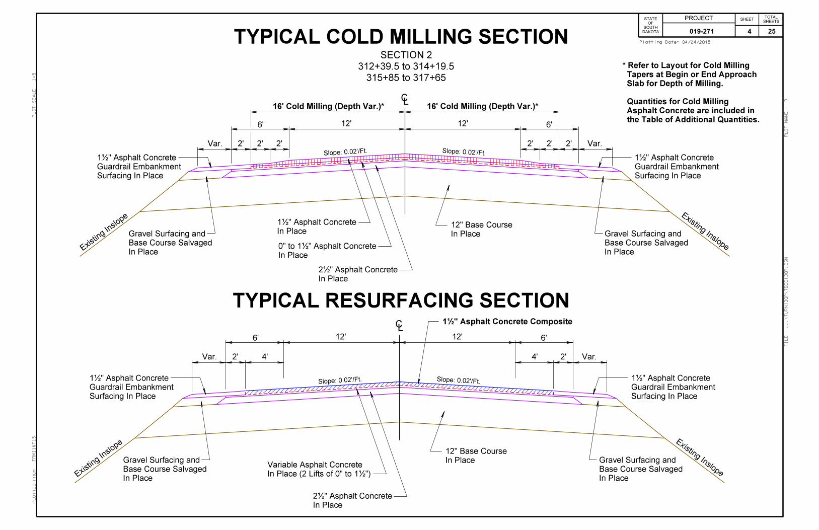
TYPICAL RESURFACING SECTION
2’
Existing Inslope
In Place
1‰" Asphalt Concrete
Slope: 0.02’/Ft.
In Place
1‰" Asphalt Concrete
12’
In Place
2‰" Asphalt Concrete
In Place
12" Base Course
In Place
Gravel Surfacing
Existin
g Inslope
2’ 2’
4’
Slope: 0.04’/Ft.
LC
Slope: 0.02’/Ft.
Slope: 0.04’/Ft.
2’
12’
2’2’
4’
Slope: 0.05’/Ft.Slope: 0.05’/Ft.
In Place
Gravel Surfacing
317+65 to 337+81
307+12 to 312+39.5
SECTION 1
1‰" Asphalt Concrete Composite
019-271 3 25
DAKOTA
SOUTH
OF
STATE PROJECT SHEETSHEETS
TOTAL
04/24/2015Plotting Date:
tr
mi1nt15
1:5
3
Plotted
Fro
m -
Plot
Scale -
File - ...\turnI3
QP\tsecI3
QP.dgn
Plot
Na
me -
Existing Inslope
In Place
1‰" Asphalt Concrete
Slope: 0.02’/Ft.
12’
In Place
2‰" Asphalt Concrete
In Place
12" Base Course
2’
6’
LC
315+85 to 317+65
312+39.5 to 314+19.5
SECTION 2
TYPICAL RESURFACING SECTION
TYPICAL COLD MILLING SECTION
Var.
In Place
0" to 1‰" Asphalt ConcreteIn Place
Base Course Salvaged
Gravel Surfacing and
2’ 2’
Surfacing In Place
Guardrail Embankment
1‰" Asphalt Concrete
Existin
g Inslope
Slope: 0.02’/Ft.2’Var.
In Place
Base Course Salvaged
Gravel Surfacing and
2’2’
Surfacing In Place
Guardrail Embankment
1‰" Asphalt Concrete
12’6’
Slope: 0.02’/Ft.
12’
In Place
2‰" Asphalt Concrete
In Place
12" Base Course
2’
6’
LC
Var.
In Place
Base Course Salvaged
Gravel Surfacing and
Surfacing In Place
Guardrail Embankment
1‰" Asphalt ConcreteSlope: 0.02’/Ft.
2’Var.
In Place
Base Course Salvaged
Gravel Surfacing and
Surfacing In Place
Guardrail Embankment
1‰" Asphalt Concrete
12’6’
In Place (2 Lifts of 0" to 1‰")
Variable Asphalt Concrete
Existin
g Inslope Existing Inslope
16’ Cold Milling (Depth Var.)*16’ Cold Milling (Depth Var.)*
4’4’
1‰" Asphalt Concrete Composite
the Table of Additional Quantities.
Asphalt Concrete are included in
Quantities for Cold Milling
Slab for Depth of Milling.
Tapers at Begin or End Approach
* Refer to Layout for Cold Milling
019-271 4 25

PROJECT
STATE OF
SOUTH DAKOTA __ ____(__)___
SHEET
10 __
TOTAL SHEETS
RATES OF MATERIALSSection 1
Rural 2 Lane307+12.00 to 312+39.50317+65.00 to 337+81.00
* Includes Approach SlabsThe Estimate of quantities is based on the following quantities of materials per station.
1.5'' ASPHALT CONCRETE COMPOSITE Crushed Aggregate 37.07 Tons
MC-70Asphalt for Prime at the rate of 0.14 ton applied 10 feet wide (5 feet wide each shoulder)(Rate = 0.3 gallon per square yard).
SS-1h or CSS-1h Asphalt for Tack at the rate of 0.09 ton applied 37 feet wide (Rate = 0.05 gallon per square yard).
FLUSH SEALSS-1h or CSS-1h Asphalt for Flush Seal at the rate of 0.09 ton applied 36 feet wide (Rate = 0.05 gallon per square yard).
Sand for Flush Seal at the rate of 1.07 tons applied 24 feet wide (Rate = 8 pounds per square yard).
TABLE OF MATERIALS QUANTITIES
BASE BASE COLD ASPHALT MC-70 SS-1h/ SS-1h/ SANDCOURSE COURSE MILLING CONCRETE ASPH. CSS-1h CSS-1h FOR
SALVAGED ASPHALT COMPOSITE FOR ASPH. ASPH. FLUSHASPHALT CONCRETE PRIME FOR FOR SEALMIX N.A.B.I. TACK FLUSH N.A.B.I.
N.A.B.I. SEAL N.A.B.I.
SECTIONTon Ton SqYd Ton Ton Ton Ton Ton
1 - - - 943 3.6 2.3 2.3 272 - - - 107 - 0.3 0.3 4
Subtotals: - - - 1050 3.6 2.6 2.6 31Additional Quantities: 60 28 1786 11 - - - -
Totals: 60 28 1786 1061 3.6 2.6 2.6 31
N.A.B.I. = Not A Bid ItemCost for shall be included in the contract unit price per ton for Asphalt Concrete Composite.
RATES OF MATERIALSSection 2
Rural 2 Lane - Between Guardrail312+39.50 to 317+65.00 (less 125.5' for one bridge &
0+00.00 to 0+00.00 less 40' for two approach slabs) * Includes Approach Slabs
The Estimate of quantities is based on the following quantities of materials per station.
1.5'' ASPHALT CONCRETE COMPOSITE Crushed Aggregate 29.60 Tons
SS-1h or CSS-1h Asphalt for Tack at the rate of 0.08 ton applied 33 feet wide (Rate = 0.05 gallon per square yard).
FLUSH SEALSS-1h or CSS-1h Asphalt for Flush Seal at the rate of 0.09 ton applied 36 feet wide (Rate = 0.05 gallon per square yard).
Sand for Flush Seal at the rate of 1.07 tons applied 24 feet wide (Rate = 8 pounds per square yard).
TABLE OF ADDITIONAL QUANTITIESBASE BASE COLD ASPHALTCOURSE COURSE MILLING CONCRETE
SALVAGED ASPHALT COMPOSITEASPHALT CONCRETE MIX
LOCATION Ton Ton SqYd Ton
Shoulder Transitions Width Mill Depth Sec. 1 312+09.5 L to 312+39.5 L 0' to 2' 0'' - 1 - 0.5 Sec. 1 317+65 R to 317+95 R 2' to 0' 0'' - 1 - 0.5
Begin/End Project - - 506 -
Begin/End Approach Slabs - - 1280 -
Guardrail Locations See Guardrail Table - 26 - 10
Pads2 Farm Entrances 20 - - - 4 Field Entrances 40 - - -
TOTALS: 60 28 1786 11
NOTES: The tonnage shown above for Base Course is based on a compacted depth of 2 inches.The tonnage shown above for Base Course Salvaged Asphalt Mix is based on a compacted depth of 4 inches.The tonnage shown above for Asphalt Concrete Composite is based on a compacted depth of 1½ inches.
The above quantities are included in the Estimate of Quantities.
N.A.B.I. = Not A Bid Item
TABLE OF PROJECT STATIONINGGROSS EXCEPTION NET
SECTION LENGTHS BRIDGE SECTIONSECTION STATION TO STATION DESCRIPTION LENGTH LENGTHS (APPR SLABS) LENGTHS LENGTHS
1 307+12.00 to 312+39.50 Rural 2 Lane 527.50' 2543.50' 2543.50' 0.482 mi.317+65.00 to 337+81.00 2016.00'
2 312+39.50 to 317+65.00 Rural 2 Lane - Betw een Guardrail 525.50' 525.50' 20.00' 125.50' 360.00' 0.068 mi.0+00.00 to 0+00.00 0.00' 20.00'
Totals 3069.00' 0.581 mi. 40.00' 0.008 mi. 125.50' 0.024 mi. 2903.50' 0.550 mi.
019-271 5 25

PROJECT
STATE OF
SOUTH DAKOTA __ ____(__)___
SHEET
11 __
TOTAL SHEETS
TABLE FOR REMOVAL AND INSTALLATION OF GUARDRAIL AND RELATED ITEMS
110E0700 110E0740 260E____ 320E1___ 629E0100 629E0300REMOVE REMOVE BASE ASPHALT 3 CABLE 3 CABLE
LOCATION 3 CABLE 3 CABLE COURSE CONCRETE GUARDRAIL GUARDRAILGUARDRAIL GUARDRAIL SALVAGED COMPOSITE SLIP BASE
ANCHOR ASPHALT ANCHORASSEMBLY MIX ASSEMBLY
BRIDGE CORNERFt Each Ton Ton Ft Each
STR.NO. 63-140-062MRM 55.13Begin Bridge L - - 2 1 - - Begin Bridge R 74 1 11 4 115 1End Bridge L 74 1 11 4 115 1End Bridge R - - 2 1 - -
019-271 TOTALS: 148 2 26 10 230 2
TABLE OF GUARDRAIL DELINEATORS & OBJECT MARKERS
LOCATION
TYPE 2 OBJECT MARKER BACK TO
BACK
TYPE 2 OBJECT MARKER
GUARDRAIL TERMINAL
END OBJECT MARKER
(ADHESIVE)
GUARDRAIL DELINEATOR
N.A.B.I. BEAM CABLE
# # # # #
BRIDGE CORNER LANE-SHOULDER Yellow White Yellow WhiteSTR.NO. 63-140-062MRM 55.13Begin Bridge L 1 4Begin Bridge R 1 1 2 3End Bridge L 1 1 2 3End Bridge R 1 4
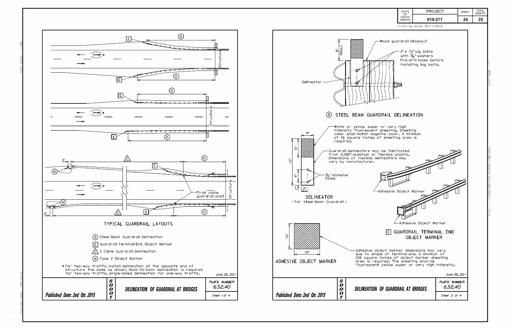
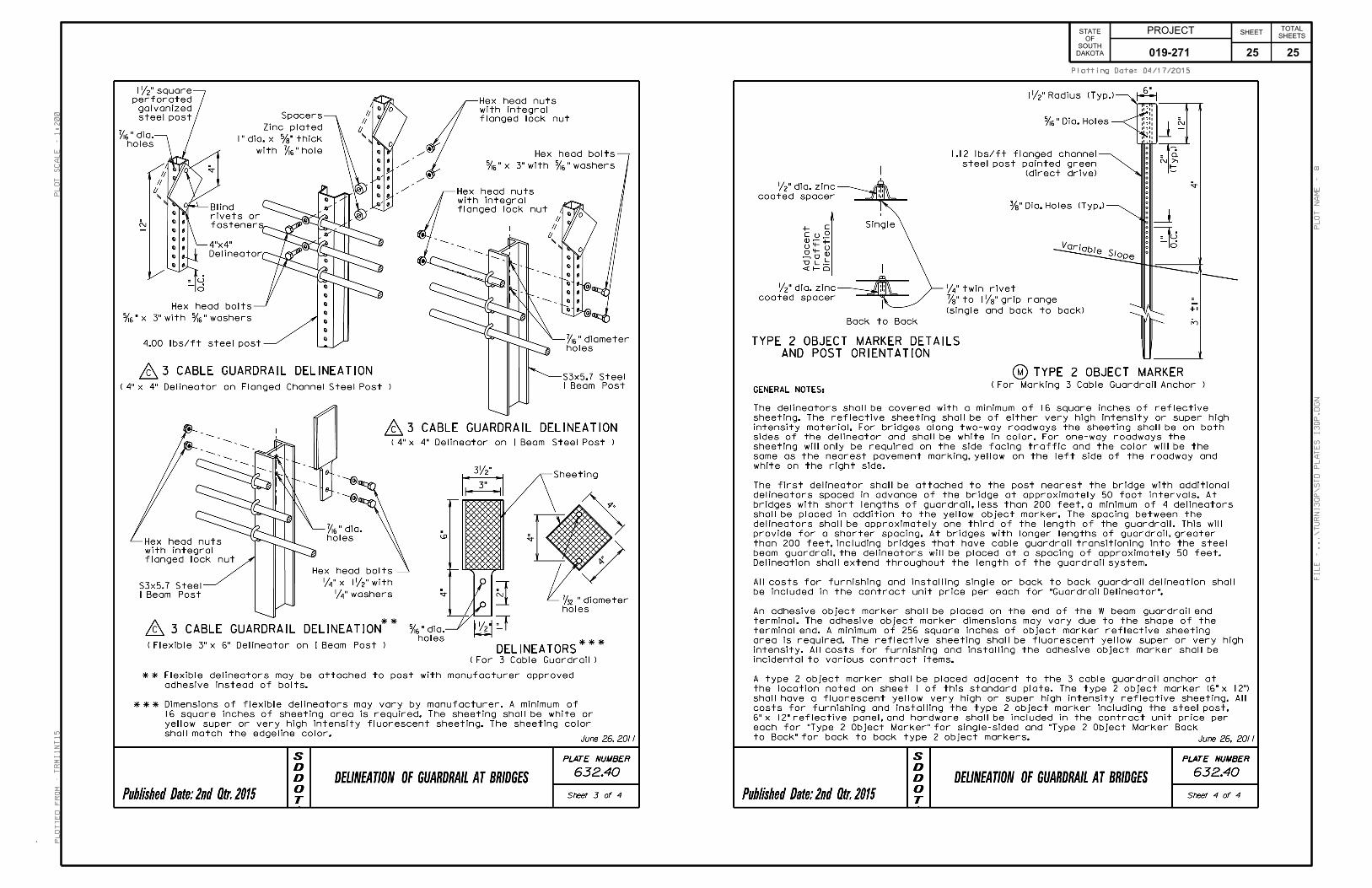
TOTALS 2 - 4 - 12 - 6# - For KEY, Refer to Standard Plate 632.40 - Sheet 1 of 4. 18N.A.B.I. = Not A Bid Item - Cost is incidental to the contract unit prices for the various items.
BEM CM
019-271 6 25

PROJECT
STATE OF
SOUTH DAKOTA __ ____(__)___
SHEET
10 __
TOTAL SHEETS
UTILITIES The Contractor shall contact the involved utility companies through South Dakota One Call (1-800-781-7474) prior to starting work. It shall be the responsibility of the Contractor to coordinate work with the utility owners to avoid damage to existing facilities. Utilities are not planned to be affected on this project. If utilities are identified near the improvement area through the SD One Call Process as required by South Dakota Codified Law 49-7A and Administrative Rule Article 20:25, the Contractor shall contact the Project Engineer to determine modifications that will be necessary to avoid utility impacts. SURFACING THICKNESS DIMENSIONS Plans tonnage will be applied even though the thickness may vary from that shown on the plans. At those locations where material must be placed to achieve a required elevation, plans tonnage may be varied to achieve the required elevation. INTERSECTING ROADS AND ENTRANCES Intersecting roads and entrances shall be satisfactorily cleared of vegetation, shaped and compacted prior to placement of mainline surfacing. This work will be considered incidental to other contract items. Separate measurement and payment will not be made. SHOULDER WORK Prior to construction, Department of Transportation Maintenance Forces will spray the shoulders to kill existing vegetation. It is the Contractor’s responsibility to notify the State a minimum of thirty days prior to starting work on the surface of the highway. The State assumes no responsibility for the effectiveness of the herbicide applied. Vegetation and accumulated material on or adjacent to the existing roadway edge shall be removed to the satisfaction of the Engineer prior to asphalt concrete resurfacing. Any remaining windrow of accumulated material shall be spread evenly on the inslope adjacent to the asphalt shoulder, to the satisfaction of the Engineer, following application of the flush seal. Shoulder work shall be incidental to other contract items. Separate measurement and payment will not be made. BASE COURSE Material obtained from Cold Milling Asphalt Concrete operations may be used as Base Course. However, if milled material is used, it must first be blended 50/50 with virgin Base Course at no additional cost for the blending. BASE COURSE, SALVAGED ASPHALT MIX Material obtained from Cold Milling Asphalt Concrete operations shall be used as Base Course, Salvaged Asphalt Mix as specified on the layout for Installation of Guardrail. WATER FOR COMPACTION Cost for water for compaction of the Base Course and Base Course, Salvaged Asphalt Mix shall be incidental to the contract unit prices for the various contract items. The moisture required at the time of compaction will be 6%± unless otherwise directed by the Engineer.
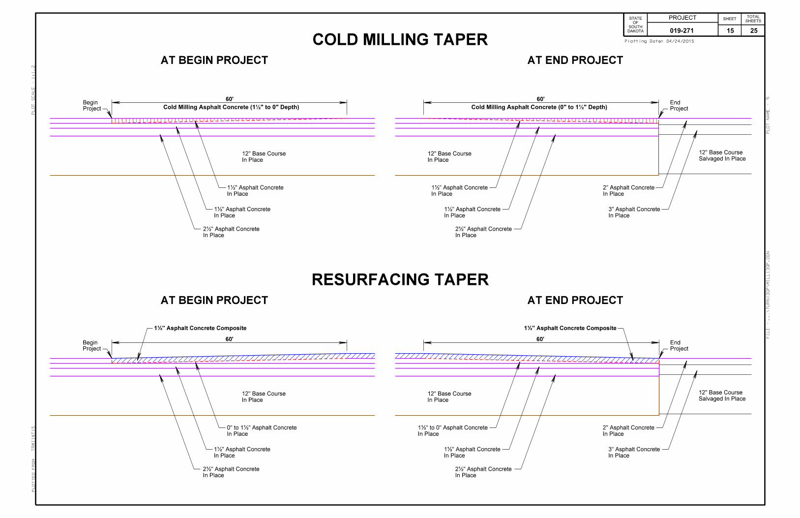
COLD MILLING ASPHALT CONCRETE Cold Milling is estimated to produce 138 tons of salvaged asphalt concrete material. Approximately 28 tons will be reused as Base Course, Salvaged Mix. Remaining unused material shall become the property of the Contractor. Estimated quantities are for information purposes only and the exact quantity will be determined upon construction. No allowance will be made for loss of expected reimbursement or loss of anticipated profit. Cold Milling Asphalt Concrete operations ahead of asphalt concrete laydown will be limited by particular job conditions and will be subject to approval of the Engineer. In no case shall cold milling operations ahead of asphalt concrete laydown operations exceed seven calendar days. The requirement for a traveling stringline shall be waived. If resurfacing as per the typical section cannot be placed immediately after cold milling at the project ends, and at bridge approach slabs then temporary asphalt mix ramps shall be placed as directed by the Engineer. Cost for placing and removing the temporary ramps shall be incidental to the contract unit prices for the various items. COLD MILLING TAPERS In order to construct the new surfacing flush with the asphalt concrete, it will be necessary to taper the depth of milling according to the details for Cold Milling Tapers. Cost for this work shall be included in the contract unit price per square yard for Cold Milling Asphalt Concrete. Taper depth of Cold Milling at locations shown below:
STA TO STA. LOCATION SIZE SQYDS 307+12 to 307+72 Begin Project 60’ L x 38’ W * 253 312+39.5 to 314+19.5 Begin Appr. Slab 180’ L x 32’ W 640 315+85 to 317+65 End Appr. Slab 180’ L x 32’ W 640 337+21 to 337+81 End Project 60’ L x 38’ W * 253 TOTAL: 1,786
* Includes granular shoulder width to provide room for resurfacing. SAWING IN EXISTING SURFACING Where new asphalt concrete is placed adjacent to existing asphalt concrete or concrete pavement, the existing asphalt concrete or concrete pavement shall be sawed full depth to a true line with a vertical face. No separate payment will be made for sawing. FLUSH SEAL Application of the flush seal shall be completed within 10 working days following completion of the asphalt concrete resurfacing. ASPHALT CONCRETE COMPOSITE Virgin mineral aggregate for the Asphalt Concrete Composite shall conform to the requirements for Class E, Type 1. The asphalt binder used in the mixture shall be PG 58-34, PG 64-28 or PG 64-34 Asphalt Binder. All other requirements in the specifications for Asphalt Concrete Composite shall apply.
RUMBLE STRIPES INSTALLATION: Rumble stripes shall be constructed according to the details of Standard Plate 320.20. Rumble stripes shall be installed in rural areas with posted speeds greater than 50 mph and are not required in urban areas. The rumble stripes shall begin at the location of the Speed Limit 65 sign as traffic is departing the built up area of a community, unless otherwise specified in the plans. The Engineer shall provide the exact start and stop locations. Rumble stripes shall not be installed on bridge decks, through curb & gutter sections, through mailbox turnouts, through intersecting roads or through approaches. They also shall not be placed within 50 feet of any railroad crossing. Gaps for rumble stripes installation as detailed on the standard plates are included with the measurement and payment. Cost for asphalt concrete rumble stripes shall be included in the contract unit price per mile for Grind 8” Rumble Strip or Stripe in Asphalt Concrete. ROADWAY CLEANING: The Contractor shall be required to remove loose material from the driving surface and/or asphalt shoulders of the roadway. Loose material may be broomed to the edge of shoulders. It shall be the Contractor’s responsibility to ensure the loose material does not enter any vegetated areas or waterways. Cost for this work shall be incidental to the contract unit price per mile for Grind 8” Rumble Strip or Stripe in Asphalt Concrete.
019-271 7 25
PROJECT
STATE OF
SOUTH DAKOTA __ ____(__)___
SHEET
11 __
TOTAL SHEETS
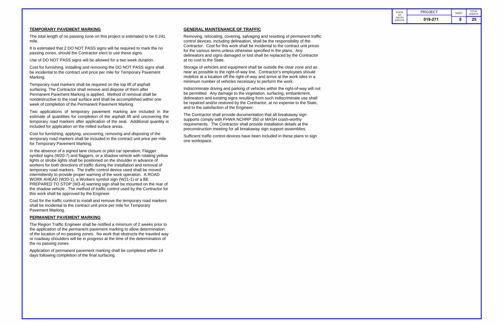
TEMPORARY PAVEMENT MARKING The total length of no passing zone on this project is estimated to be 0.241 mile. It is estimated that 2 DO NOT PASS signs will be required to mark the no passing zones, should the Contractor elect to use these signs. Use of DO NOT PASS signs will be allowed for a two week duration. Cost for furnishing, installing and removing the DO NOT PASS signs shall be incidental to the contract unit price per mile for Temporary Pavement Marking. Temporary road markers shall be required on the top lift of asphalt surfacing. The Contractor shall remove and dispose of them after Permanent Pavement Marking is applied. Method of removal shall be nondestructive to the road surface and shall be accomplished within one week of completion of the Permanent Pavement Marking. Two applications of temporary pavement marking are included in the estimate of quantities for completion of the asphalt lift and uncovering the temporary road markers after application of the seal. Additional quantity is included for application on the milled surface areas. Cost for furnishing, applying, uncovering, removing and disposing of the temporary road markers shall be included in the contract unit price per mile for Temporary Pavement Marking. In the absence of a signed lane closure or pilot car operation, Flagger symbol signs (W20-7) and flaggers, or a shadow vehicle with rotating yellow lights or strobe lights shall be positioned on the shoulder in advance of workers for both directions of traffic during the installation and removal of temporary road markers. The traffic control device used shall be moved intermittently to provide proper warning of the work operation. A ROAD WORK AHEAD (W20-1), a Workers symbol sign (W21-1) or a BE PREPARED TO STOP (W3-4) warning sign shall be mounted on the rear of the shadow vehicle. The method of traffic control used by the Contractor for this work shall be approved by the Engineer. Cost for the traffic control to install and remove the temporary road markers shall be incidental to the contract unit price per mile for Temporary Pavement Marking. PERMANENT PAVEMENT MARKING The Region Traffic Engineer shall be notified a minimum of 2 weeks prior to the application of the permanent pavement marking to allow determination of the location of no passing zones. No work that obstructs the traveled way or roadway shoulders will be in progress at the time of the determination of the no passing zones. Application of permanent pavement marking shall be completed within 14 days following completion of the final surfacing.
GENERAL MAINTENANCE OF TRAFFIC Removing, relocating, covering, salvaging and resetting of permanent traffic control devices, including delineation, shall be the responsibility of the Contractor. Cost for this work shall be incidental to the contract unit prices for the various items unless otherwise specified in the plans. Any delineators and signs damaged or lost shall be replaced by the Contractor at no cost to the State. Storage of vehicles and equipment shall be outside the clear zone and as near as possible to the right-of-way line. Contractor’s employees should mobilize at a location off the right-of-way and arrive at the work sites in a minimum number of vehicles necessary to perform the work. Indiscriminate driving and parking of vehicles within the right-of-way will not be permitted. Any damage to the vegetation, surfacing, embankment, delineators and existing signs resulting from such indiscriminate use shall be repaired and/or restored by the Contractor, at no expense to the State, and to the satisfaction of the Engineer. The Contractor shall provide documentation that all breakaway sign supports comply with FHWA NCHRP 350 or MASH crash-worthy requirements. The Contractor shall provide installation details at the preconstruction meeting for all breakaway sign support assemblies. Sufficient traffic control devices have been included in these plans to sign one workspace.
019-271 8 25
PROJECT
STATE OF
SOUTH DAKOTA __ ____(__)___
SHEET
12 __
TOTAL SHEETS
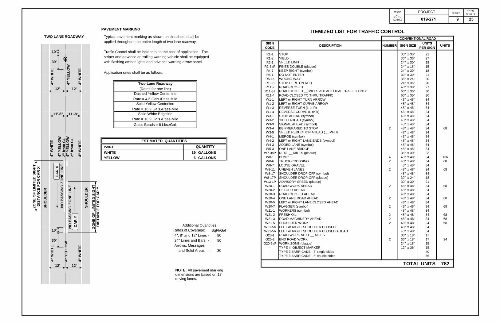
PAVEMENT MARKING
TWO LANE ROADWAY Typical pavement marking as shown on this sheet shall beapplied throughout the entire length of two lane roadway.
10' Traffic Control shall be incidental to the cost of application. Thestriper and advance or trailing warning vehicle shall be equipped
30' with flashing amber lights and advance warning arrow panel.
Application rates shall be as follows:PAINT
Two Lane Roadway12' 12' (Rates for one line)
Dashed Yellow CenterlineRate = 4.6 Gals./Pass-Mile
Solid Yellow CenterlineRate = 16.9 Gals./Pass-Mile
11'-8" 11'-8" Solid White EdgelineRate = 16.9 Gals./Pass-MileGlass Beads = 8 Lbs./Gal.
ESTIMATED QUANTITIESPAINT QUANTITYWHITE 19 GALLONSYELLOW 6 GALLONS
Included in the above quantities are: Additional White Additional YellowDescription PAINT Gallons Description Gallons4" Lines 0' 0 Transitions 0 Ea 08'' Lines 0' 0 4'' Skip Lines 0' 012'' Gore Lines 0' 0 8'' Lines 0' 0Crosswalks 0 Ea 0 12'' Lines 0' 024'' Stop Lines 0' 0 24'' Hatches 0' 024" Hatches 0' 0 Solid Areas 0sf 0Solid Areas 0sf 0 Additional Yellow: 0ArrowsLeft Arrows 0 Ea 0 Additional Quantities
10' Right Arrows 0 Ea 0 Rates of Coverage: SqFt/GalStraight Arrows 0 Ea 0 4", 8" and 12" Lines - 80
30' Combo Arrows 0 Ea 0 24" Lines and Bars - 50Lane Drop Arrows 0 Ea 0 Arrows, MessagesMessages and Solid Areas - 30STOP 0 Ea 0STOP AHEAD 0 Ea 0
12' 12' R X R with Bars 0 Ea 0SCHOOL X-ING 0 Ea 0
Additional White: 0NOTE: All pavement marking dimensions are based on 12' driving lanes.
SHO
ULD
ER
4" W
HIT
E
ZON
E O
F LI
MIT
ED S
IGH
TD
ISTA
NC
E FO
R C
AR
X
ZON
E O
F LI
MIT
ED S
IGH
TD
ISTA
NC
E FO
R C
AR
Y
NO
PA
SSIN
G Z
ON
E LI
NE
4" Y
ELLO
W2"
from
CL
4" W
HIT
E
4" W
HIT
E
4" W
HIT
E
4" Y
ELLO
WN
O P
ASS
ING
ZO
NE
LIN
E4"
YEL
LOW
2" fr
om C
L
SHO
ULD
ER
4" W
HIT
E
4" W
HIT
E
4" Y
ELLO
W
CA
R X
CA
R Y
CL
ITEMIZED LIST FOR TRAFFIC CONTROLCONVENTIONAL ROAD
SIGN CODE DESCRIPTION NUMBER SIGN SIZE UNITS
PER SIGN UNITS0.000001
R1-1 STOP 30'' x 30'' 21R1-2 YIELD 36'' x 36'' 27R2-1 SPEED LIMIT __ 24'' x 30'' 18
R2-6aP FINES DOUBLE (plaque) 24'' x 18'' 15R4-7 KEEP RIGHT (symbol) 24'' x 30'' 18R5-1 DO NOT ENTER 30'' x 30'' 21R5-1a WRONG WAY 36'' x 24'' 20R10-6 STOP HERE ON RED 24'' x 36'' 20R11-2 ROAD CLOSED 48'' x 30'' 27R11-3a ROAD CLOSED __ MILES AHEAD LOCAL TRAFFIC ONLY 60'' x 30'' 30R11-4 ROAD CLOSED TO THRU TRAFFIC 60'' x 30'' 30W1-1 LEFT or RIGHT TURN ARROW 48'' x 48'' 34W1-2 LEFT or RIGHT CURVE ARROW 48'' x 48'' 34W1-3 REVERSE TURN (L or R) 48'' x 48'' 34W1-4 REVERSE CURVE (L or R) 48'' x 48'' 34W3-1 STOP AHEAD (symbol) 48'' x 48'' 34W3-2 YIELD AHEAD (symbol) 48'' x 48'' 34W3-3 SIGNAL AHEAD (symbol) 48'' x 48'' 34W3-4 BE PREPARED TO STOP 2 48'' x 48'' 34 68W3-5 SPEED REDUCTION AHEAD (__ MPH) 48'' x 48'' 34W4-1 MERGE (symbol) 48'' x 48'' 34W4-2 LEFT or RIGHT LANE ENDS (symbol) 48'' x 48'' 34W4-3 ADDED LANE (symbol) 48'' x 48'' 34W5-3 ONE LANE BRIDGE 48'' x 48'' 34
W7-3aP NEXT __ MILES (plaque) 36'' x 30'' 23W8-1 BUMP 4 48'' x 48'' 34 136W8-6 TRUCK CROSSING 2 48'' x 48'' 34 68W8-7 LOOSE GRAVEL 48'' x 48'' 34W8-11 UNEVEN LANES 2 48'' x 48'' 34 68W8-17 SHOULDER DROP-OFF (symbol) 48'' x 48'' 34
W8-17P SHOULDER DROP-OFF (plaque) 30'' x 24'' 18W13-1P ADVISORY SPEED (plaque) 30'' x 30'' 21W20-1 ROAD WORK AHEAD 2 48'' x 48'' 34 68W20-2 DETOUR AHEAD 48'' x 48'' 34W20-3 ROAD CLOSED AHEAD 48'' x 48'' 34W20-4 ONE LANE ROAD AHEAD 2 48'' x 48'' 34 68W20-5 LEFT or RIGHT LANE CLOSED AHEAD 48'' x 48'' 34W20-7 FLAGGER (symbol) 2 48'' x 48'' 34 68W21-1 WORKERS (symbol) 48'' x 48'' 34W21-2 FRESH OIL 2 48'' x 48'' 34 68W21-3 ROAD MACHINERY AHEAD 2 48'' x 48'' 34 68W21-5 SHOULDER WORK 2 48'' x 48'' 34 68
W21-5a LEFT or RIGHT SHOULDER CLOSED 48'' x 48'' 34W21-5b LEFT or RIGHT SHOULDER CLOSED AHEAD 48'' x 48'' 34G20-1 ROAD WORK NEXT __ MILES 36'' x 18'' 17G20-2 END ROAD WORK 2 36'' x 18'' 17 34
G20-5aP WORK ZONE (plaque) 24'' x 18'' 15- TYPE III OBJECT MARKER 12'' x 36'' 15- TYPE 3 BARRICADE - 8' single sided 40- TYPE 3 BARRICADE - 8' double sided 56
0.000001
TOTAL UNITS 7821
019-271 9 25
Work Vehicle
(48"X48")
AHEAD
(TYPICAL)
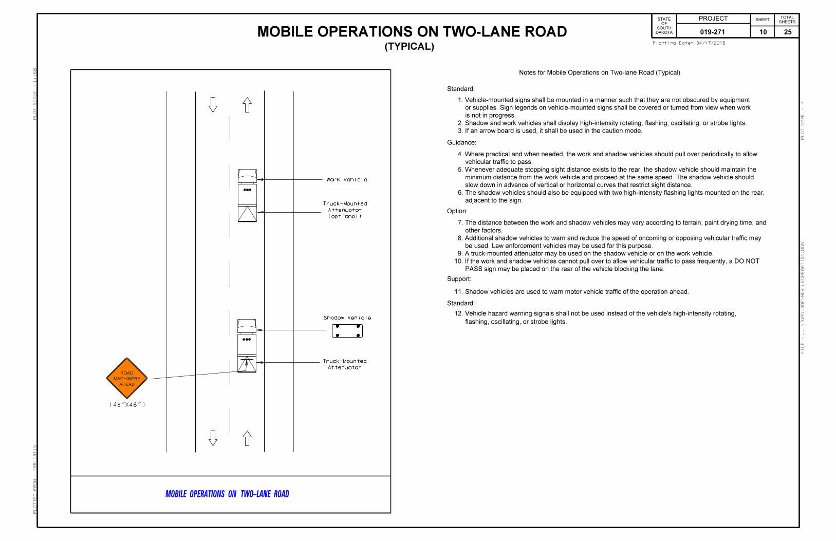
MOBILE OPERATIONS ON TWO-LANE ROAD
ROAD
MACHINERY
Shadow Vehicle
MOBILE OPERATIONS ON TWO-LANE ROAD
Notes for Mobile Operations on Two-lane Road (Typical)
Standard:
1. Vehicle-mounted signs shall be mounted in a manner such that they are not obscured by equipment
or supplies. Sign legends on vehicle-mounted signs shall be covered or turned from view when work
is not in progress.
2. Shadow and work vehicles shall display high-intensity rotating, flashing, oscillating, or strobe lights.
3. If an arrow board is used, it shall be used in the caution mode.
Guidance:
4. Where practical and when needed, the work and shadow vehicles should pull over periodically to allow
vehicular traffic to pass.
5. Whenever adequate stopping sight distance exists to the rear, the shadow vehicle should maintain the
minimum distance from the work vehicle and proceed at the same speed. The shadow vehicle should
slow down in advance of vertical or horizontal curves that restrict sight distance.
6. The shadow vehicles should also be equipped with two high-intensity flashing lights mounted on the rear,
adjacent to the sign.
Option:
7. The distance between the work and shadow vehicles may vary according to terrain, paint drying time, and
other factors.
8. Additional shadow vehicles to warn and reduce the speed of oncoming or opposing vehicular traffic may
be used. Law enforcement vehicles may be used for this purpose.
9. A truck-mounted attenuator may be used on the shadow vehicle or on the work vehicle.
10. If the work and shadow vehicles cannot pull over to allow vehicular traffic to pass frequently, a DO NOT
PASS sign may be placed on the rear of the vehicle blocking the lane.
Support:
11. Shadow vehicles are used to warn motor vehicle traffic of the operation ahead.
Standard:
flashing, oscillating, or strobe lights.
12. Vehicle hazard warning signals shall not be used instead of the vehicle’s high-intensity rotating,
Attenuator
Truck-Mounted
(optional)
Attenuator
Truck-Mounted
DAKOTA
SOUTH
OF
STATE PROJECT SHEETSHEETS
TOTAL
04/17/2015Plotting Date:
tr
mi1nt15
1:160
4
Plotted
Fro
m -
Plot
Scale -
File - ...\turnI3
QP\
Mobile
Operation.dgn
Plot
Na
me -
019-271 10 25

DAKOTA
SOUTH
OF
STATE PROJECT SHEETSHEETS
TOTAL
04/17/2015Plotting Date:
tr
mi1nt15
1:200
1
Plotted
Fro
m -
Plot
Scale -
File - ...\tc
Std
Plates I3
QP.dgn
Plot
Na
me -
019-271 11 25
DAKOTA
SOUTH
OF
STATE PROJECT SHEETSHEETS
TOTAL
04/17/2015Plotting Date:
tr
mi1nt15
1:200
2
Plotted
Fro
m -
Plot
Scale -
File - ...\tc
Std
Plates I3
QP.dgn
Plot
Na
me -
019-271 12 25
DAKOTA
SOUTH
OF
STATE PROJECT SHEETSHEETS
TOTAL
04/17/2015Plotting Date:
tr
mi1nt15
1:200
3
Plotted
Fro
m -
Plot
Scale -
File - ...\tc
Std
Plates I3
QP.dgn
Plot
Na
me -
019-271 13 25
DAKOTA
SOUTH
OF
STATE PROJECT SHEETSHEETS
TOTAL
04/17/2015Plotting Date:
tr
mi1nt15
1:200
4
Plotted
Fro
m -
Plot
Scale -
File - ...\tc
Std
Plates I3
QP.dgn
Plot
Na
me -
019-271 14 25
DAKOTA
SOUTH
OF
STATE PROJECT SHEETSHEETS
TOTAL
04/24/2015Plotting Date:
tr
mi1nt15
1:1.2
5
Plotted
Fro
m -
Plot
Scale -
File - ...\turnI3
QP\
millI3
QP.dgn
Plot
Na
me -
COLD MILLING TAPER
RESURFACING TAPER
60’
Cold Milling Asphalt Concrete (1‰" to 0" Depth)
60’
In Place
1‰" Asphalt Concrete
In Place
2‰" Asphalt Concrete
In Place
1‰" Asphalt Concrete
In Place
1‰" Asphalt Concrete
In Place
2‰" Asphalt Concrete
60’
In Place
3" Asphalt Concrete
In Place
2" Asphalt Concrete
Cold Milling Asphalt Concrete (0" to 1‰" Depth)
60’
In Place
1‰" Asphalt Concrete
In Place
2‰" Asphalt Concrete
In Place
1‰" Asphalt Concrete
In Place
1‰" Asphalt Concrete
In Place
2‰" Asphalt Concrete
Salvaged In Place
12" Base Course
Salvaged In Place
12" Base Course
In Place
3" Asphalt Concrete
In Place
2" Asphalt Concrete
In Place
12" Base Course
In Place
12" Base Course
In Place
12" Base Course
In Place
12" Base Course
AT BEGIN PROJECT AT END PROJECT
AT BEGIN PROJECT AT END PROJECT
In Place
0" to 1‰" Asphalt Concrete
In Place
1‰" to 0" Asphalt Concrete
Project
Begin
Project
Begin
Project
End
Project
End
1‰" Asphalt Concrete Composite 1‰" Asphalt Concrete Composite
019-271 15 25

DAKOTA
SOUTH
OF
STATE PROJECT SHEETSHEETS
TOTAL
04/24/2015Plotting Date:
tr
mi1nt15
1:1.2
6
Plotted
Fro
m -
Plot
Scale -
File - ...\turnI3
QP\
millI3
QP.dgn
Plot
Na
me -
COLD MILLING TAPER
RESURFACING TAPER
120’
In Place
1‰" Asphalt Concrete
Cold Milling Asphalt Concrete (0" to 3" Depth)
12" Base Course In Place
In Place
2‰" Asphalt Concrete
60’
Slab
Appr
or End
Begin
In Place
1‰" Asphalt Concrete
Cold Milling Asphalt Concrete (3" to 1‰" Depth)
Place
In
Slab
Appr
120’
In Place
1‰" Asphalt Concrete
12" Base Course In Place
In Place
2‰" Asphalt Concrete
60’
Slab
Appr
or End
Begin
Place
In
Slab
Appr
In Place
1‰" to 0" Asphalt Concrete
AT BEGIN OR END APPROACH SLAB
AT BEGIN OR END APPROACH SLAB
1‰" Asphalt Concrete Composite
1‰" Asphalt Concrete Composite
019-271 16 25
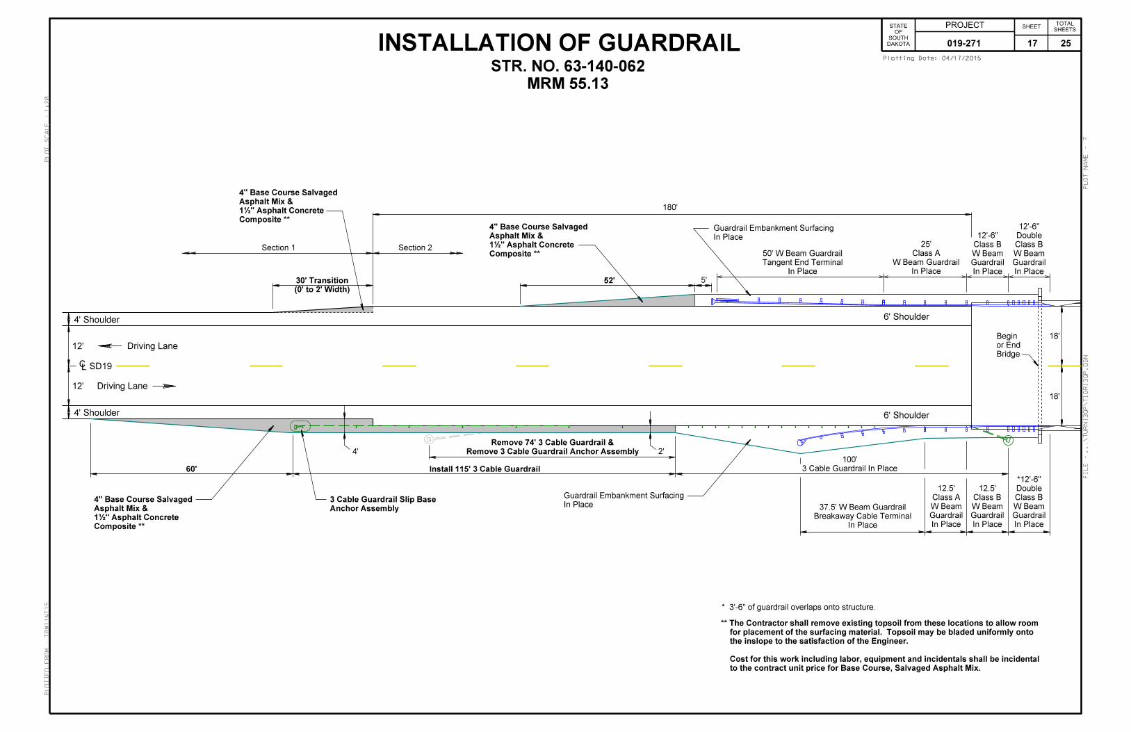
INSTALLATION OF GUARDRAIL DAKOTA
SOUTH
OF
STATE PROJECT SHEETSHEETS
TOTAL
04/17/2015Plotting Date:
tr
mi1nt15
1:20
7
Plotted
Fro
m -
Plot
Scale -
File - ...\turnI3
QP\tigrI3
QP.dgn
Plot
Na
me -
MRM 55.13
STR. NO. 63-140-062
* 3’-6" of guardrail overlaps onto structure.
Anchor Assembly
3 Cable Guardrail Slip Base
Driving Lane
12’
12’
Driving Lane
4’ Shoulder
18’
SD19CL
18’
Bridge
or End
Begin
6’ Shoulder
6’ Shoulder
4’ Shoulder
In Place
Guardrail
W Beam
Class B
Double
*12’-6"
In Place
Guardrail
W Beam
Class A
12.5’
In Place
Guardrail
W Beam
Class B
12.5’
In Place
Breakaway Cable Terminal
37.5’ W Beam Guardrail
3 Cable Guardrail In Place
100’
60’ Install 115’ 3 Cable Guardrail
5’52’
Section 1 Section 2
180’
(0’ to 2’ Width)
30’ Transition
In Place
Tangent End Terminal
50’ W Beam Guardrail
In Place
Guardrail
W Beam
Class B
12’-6"
In Place
Guardrail
W Beam
Class B
Double
12’-6"
In Place
W Beam Guardrail
Class A
25’
4’
In Place
Guardrail Embankment Surfacing
In Place
Guardrail Embankment Surfacing
Remove 3 Cable Guardrail Anchor Assembly
Remove 74’ 3 Cable Guardrail &
2’
Composite **
1‰" Asphalt Concrete
Asphalt Mix &
4" Base Course Salvaged
Composite **
1‰" Asphalt Concrete
Asphalt Mix &
4" Base Course Salvaged
Composite **
1‰" Asphalt Concrete
Asphalt Mix &
4" Base Course Salvaged
to the contract unit price for Base Course, Salvaged Asphalt Mix.
Cost for this work including labor, equipment and incidentals shall be incidental
the inslope to the satisfaction of the Engineer.
for placement of the surfacing material. Topsoil may be bladed uniformly onto
** The Contractor shall remove existing topsoil from these locations to allow room
019-271 17 25

DAKOTA
SOUTH
OF
STATE PROJECT SHEETSHEETS
TOTAL
04/17/2015Plotting Date:
tr
mi1nt15
1:200
1
Plotted
Fro
m -
Plot
Scale -
File - ...\turnI3
QP\
Std
Plates I3
QP.dgn
Plot
Na
me -
019-271 18 25

DAKOTA
SOUTH
OF
STATE PROJECT SHEETSHEETS
TOTAL
04/17/2015Plotting Date:
tr
mi1nt15
1:200
2
Plotted
Fro
m -
Plot
Scale -
File - ...\turnI3
QP\
Std
Plates I3
QP.dgn
Plot
Na
me -
019-271 19 25

DAKOTA
SOUTH
OF
STATE PROJECT SHEETSHEETS
TOTAL
04/17/2015Plotting Date:
tr
mi1nt15
1:200
3
Plotted
Fro
m -
Plot
Scale -
File - ...\turnI3
QP\
Std
Plates I3
QP.dgn
Plot
Na
me -
019-271 20 25
DAKOTA
SOUTH
OF
STATE PROJECT SHEETSHEETS
TOTAL
04/17/2015Plotting Date:
tr
mi1nt15
1:200
4
Plotted
Fro
m -
Plot
Scale -
File - ...\turnI3
QP\
Std
Plates I3
QP.dgn
Plot
Na
me -
019-271 21 25

DAKOTA
SOUTH
OF
STATE PROJECT SHEETSHEETS
TOTAL
04/17/2015Plotting Date:
tr
mi1nt15
1:200
5
Plotted
Fro
m -
Plot
Scale -
File - ...\turnI3
QP\
Std
Plates I3
QP.dgn
Plot
Na
me -
019-271 22 25
DAKOTA
SOUTH
OF
STATE PROJECT SHEETSHEETS
TOTAL
04/17/2015Plotting Date:
tr
mi1nt15
1:200
6
Plotted
Fro
m -
Plot
Scale -
File - ...\turnI3
QP\
Std
Plates I3
QP.dgn
Plot
Na
me -
019-271 23 25
DAKOTA
SOUTH
OF
STATE PROJECT SHEETSHEETS
TOTAL
04/17/2015Plotting Date:
tr
mi1nt15
1:200
7
Plotted
Fro
m -
Plot
Scale -
File - ...\turnI3
QP\
Std
Plates I3
QP.dgn
Plot
Na
me -
019-271 24 25
DAKOTA
SOUTH
OF
STATE PROJECT SHEETSHEETS
TOTAL
04/17/2015Plotting Date:
tr
mi1nt15
1:200
8
Plotted
Fro
m -
Plot
Scale -
File - ...\turnI3
QP\
Std
Plates I3
QP.dgn
Plot
Na
me -
019-271 25 25