lncs 3088 - making user’s sketch into a motion picture for ... · making user’s sketch into a...
TRANSCRIPT

J. Lladós and Y.-B. Kwon (Eds.): GREC 2003, LNCS 3088, pp. 341–352, 2004. © Springer-Verlag Berlin Heidelberg 2004
Making User’s Sketch into a Motion Picture for Visual Storytelling on the Web
Yang-Hee Nam
Division of Digital Media, Ewha Womans University, 11-1 Daehyun-dong, Seodaemun-gu, Seoul, South Korea
Abstract. This paper introduces a cheap engineering solution of authoring and presenting user’s own story in the form of animation on the world wide web. Most of existing story-making tools allow users to choose characters from a given database because model building task is time-consuming and requires some level of expertise. Comparatively, we suggest an easy ‘three-dimensionalizing’ method by incorporating user’s own 2D sketches of charac-ters, scenes and text to the story and by making them finally be presented in the form of 3D-like animation semi-automatically on the web.
1 Introduction
A Story is one of the important ways of communication and of cultivating creativity. For decades, most of elementary school teachers in Korea have given their students a so-called ‘picture diary’ homework so as to cultivate children’s ability of thought, imagination and expression.
In this digital era, there have been digitally shared authoring tools such as wiki wiki web and storyspace [1]. These are text-based softwares regarding efficiency appropriate for serious writers. There have also been many commercial tools or games developed for visual story making such as SimCity, StoryMaker, ComicChat, and so on [2]. These can offer easy and fast ways of developing stories with corre-sponding visuals. The main purpose of these softwares, however, is usually not gen-eral story making but special purpose games or chatting. Also, the user’s creativity tends to be limited to build expectable stories with some choice of characters and scene objects from the existing database.
Comparatively, we present a general story building environment where our re-search focuses on a way of incorporating user’s own sketches of characters and scenes for the story. The story can finally be presented in the form of 3D-like anima-tion on the web. Usually, there are two ways of creating user’s own objects. One is to let users draw every necessary image frames for the animation. The other way lets users build their own 3-dimensional graphical models representing scenes and charac-ters. The problem is that the both approaches are time consuming and quite difficult for general users to use. They thus make users difficult to focus on the story devel-

342 Y.-H. Nam
opment itself. Online authoring is, of course, not recommended in such time consum-ing approaches.
Our approach deals with the above problems by giving users 2D constrained sketching environment and by putting the cartoon-style sketches into a 3-dimensionalized scene. The sketches are drawn in 2-dimensional plane, but they stand and behave in a 3D world as paper-dolls that children often play with in a real-world. The 3-dimensionalizing process is based on automatic sketch analysis and generation of view sequences according to the story text.
The resulting web-based digital storytelling system will have further applications on various fields such as online education, interactive movies with multiple users’ participation, and other interactive multimedia services [3].
The next section introduces an overall design of online storytelling framework, and the 3rd section describes sketch analysis methods for model building. Section 4 shows how the sketched objects are incorporated into the story animation with auto-matic camera control according to time. We finally give a conclusion and discuss our further research in Section 5.
2 Design of a Web-based Visual Storytelling System
This section discusses system requirements for shared digital storytelling. We first present our design of system components. By web-based visual storytelling system, we refer such a system in that the users can build their story text with the associated visuals while cooperating with other remote users. Also, a story will be developed with an appropriate timeline.
The main requirements for this kind of systems are identified as below:
• The ability of fast and easy modeling for the shape, attributes and behavior for main characters and scenes.
• The capability of scripting or inputing user’s story text across time. • Association with visuals and texts in an appropriate timeline. • The capability of inter-communication between users commonly participating
to an authoring process. • Automatic and appropriate synchronization of authoring status between users
sharing a story. • The playback system for visualizing the spatio-temporal development of a
story. This reveals the flow of text with the corresponding camera movement for the generating scenes.
Based on the above requirements, the client architecture of our web-based visual storytelling system is designed as Fig. 1. The main component named as Story Builder allows users the basic establishment for a target story such as date and weather condition. Also, it provides the most important part of the system - text input and visual sketchbook environment. These two different kinds of inputs can be asso-ciated each other using timeline manager. Users can also specify where to put their

Making User’s Sketch into a Motion Picture for Visual Storytelling on the Web 343
sketch objects into the scene using the visual sketchbook. And a remote user can help organizing scenes using helper tools.
Visualization Manager is responsible for generating the animation sequence of scenes built from the sketches. If it generates animation sequences directly with 2D images given by users, it should solve 2D interpolation problem which is known very difficult without manual indication of the frame correspondence. Requesting users to specify such a correspondence for image frames is non-sense in real-time authoring systems. It also requires users to draw many numbers of images in dense intervals of time.
On the other hand, our approach analyses the 2D sketch to build the basic 3D out-line structure so that 3D-like animation effect can be generated by the continuous change of viewpoint and character poses. In this case, only one or two sketch is enough for describing a diary-length story.
Networking manager transfers the story updates of a client to the server so as to keep the consistency between the clients participating the story authoring. While updating the story, a user can also communicate with remote users about the storyline and get help from a remote user for the visual authoring task that could be relatively difficult for novice young users.
Fig. 1. Client System Architecture
3 Sketch Analysis for Making Story Objects Alive
This section presents the main idea for building a story animation from user’s simple 2D drawing input. The basic concept is to make use of the information on the 3-dimensional structure implied in the sketch.
Story Builder
- Basic Setup - Story Text Input - Timeline Manager - Visual Sketchbook - Scene Organizing Helper
Visualization Manager
- Camera Interpolation - Synchronized Playback
of Text and Visuals
Networking Manager
(Sharing Graphic Updates and Story Text)
(Chatting Module)
toWeb Server
User

344 Y.-H. Nam
There has been an existing approach applied to generate a 3D-like navigation ef-fect from an input image [4][5]. We can apply the approach for building an anima-tion from a background sketch. We should also provide a method to put non-static objects into the scene and to move them. However, the existing approach to construct 3D model from 2D images are not efficient enough to apply for the real-time web based authoring [6][7][8]. Otherwise, we can model 3D objects with independent off-line tools and bring them later into web application environment, but it is also diffi-cult and time-consuming for non-expert users. To avoid the needs of complex 3D modelling, we employ a ‘paper-doll metaphor’ for the main objects such as actors. In the following subsections, we introduce a paper-doll metaphor for modelling story objects and the sketch based background imaging method.
3.1 Projective Mesh Guidelines for Sketching a Story Background
Story background is a scene where the story happens. To construct a 3-dimensional background from a 2D image, we provide projective mesh guidelines to help users to set their background sketch plan. Projective mesh guidelines represent 3-D spatial plans when spaces are projected onto the 2D images. We employed 6 types of projec-tive meshes that represent a space with a vanishing point(type-1) as shown in fig. 2(a), a horizontal plan(type-2) as in fig. 2(b), a diagonal plan(type-3), an arc-type plan(type-4), left-right vanishing points(type-5), and a triangle plan(type-6). Among many projective space plan, fig. 3 and fig. 4 shows a type-1 and type-2 mesh guide-lines that are useful in the majority of simply sketched scenes. The type-1 mesh pro-vides a sketch plan for the scene with a vanishing in it. Users can move the vanishing point interactively so that the drawn image can fit to the guideline. It is then easy to identify the sketch regions corresponding to the 3D faces of a hexahedron. The im-age in each region is mapped into the corresponding face as a texture. Now that the 3D scene is modelled, viewpoint animation can easily be generated.
Fig. 2. Examples of projective mesh guidelines
(a) type-1 mesh overlapped (b) type-2(horizontal)
onto the user sketch mesh guideline

345
Fig. 4. Example of Reconstruction of type-2 (horizontal) mesh
3.2 Analysis of 2D Actor Sketch Using a Paper-Doll Metaphor
For putting the objects that play main roles as story actors into 3D animation, we suggest a so-called ‘paper-doll metaphor’ so that users can make and control their own actors easily enough. We are mentioning such a paper-doll having the following properties:
• People can easily draw and create paper-doll, while constructing a 3D doll model is a difficult task.
• In real-life, people cut a paper-doll running after one’s contour. The doll has a flat shape without volume.
• Once it is cut, people can make it stand and move in a 3D space. All the motions of a paper-doll are basically controlled by bending some major joints in the body. Each joint motion has one-degree of freedom since a paper-doll can bend in the typical folding direction. Otherwise, the paper might be torn into pieces.
We thus define the paper-doll metaphor as controlling virtual actors according to the above properties. That is, the sketched image of an actor is digitally cut out according to its contour and is modelled as a flat polygonal shape without volume.
11 22
33 44
55 66
77 88
Back Wall : 3,4,5,6
Right Wall : 3,4,5,6
Ceiling : 1,2,3,4
Bottom : 5,6,7,8
(b) 3D Reconstruction Model
Left Wall : 3,4,5,6
(b) Walls corresponding to 2D Sketch Polygons
Left Wall Right Wall
Ceiling
Bottom
Back Wall
55
1133
991122
6644
2288
1111
55 33
9977
11 2288
44 66
11
(c) Reconstructed 3D Model
Vanishing Point 77
(a)Type-1 Mesh
(a) Type-2 Mesh
Fig. 3. Image regions and their target 3D scene in the case of type-1 mesh [4]
Making User’s Sketch into a Motion Picture for Visual Storytelling on the Web

346 Y.-H. Nam
Fig. 5. Digital cutting and skeleton matching process for a digital paper-doll
Fig. 5 shows the process from automatic digital image cutting and skeleton matching against predefined body structure template. First, user draws an actor on a blank background. Otherwise, user can also load and use some popular character image. In both cases, the second step is extracing the contour of the sketched object by flood filling method [9]. As the silhouette extraction by flood filling fails if there is any hole in the shilouette line, our interactive method warns users to draw connected curves at least for the outline. Yet the constraint does not request users additional effort or difficulty in drawing. In the third step, we cut out the character’s outer region found in the previous step. During this process, the drawings of character’s inner decoration are ignored. They will be considered later to map as a texture image to a 3D reconstructed model. The fourth step is carrying out a thinning on the identified object region [10]. Once the skeleton is extracted from a given sketch, we try to match between the skeleton and the corresponding template structure. During the final step, the positions of joints and the length of limbs of the skeleton template are adjusted according to the user character’s relative part sizes. Using the upper and lower bounds of the spine, also the head and feet of the template, it is resized to fit the extracted bounds of the sketched object. This resulting skeleton structure will be used to control the motion of a paper-doll-like actor.
Though we can of course use more sophisticated image processing algorithm for this process of digital cutting and skeleton matching, we found it is very important that the effectiveness in time and ease of authoring on the web is kept for the usability.
Now, to use the skeleton structure for motion control, we have to know where the joints are and how their rotation axes is defined. We achieve this by predefining the template of 10 joints for human. The template has the information on the rotation axis for each joint so that the joint can bend around the axis just like folding a paper.
After matching each joint structure, the skin groups are built up by associating them with the limbs between relevant joints. Building up the groups of limbs and skin is done by dividing the polygon of the doll based on the bending axis line. As shown in fig. 6, each of the bending axes is defined as passing through the middle of the associated joint and perpendicular to the connecting limb. It thus crosses the contour line of the paper-doll. These bending axes correspond to the folding lines when children plays with a paper-doll. Since the angles of two adjacent limbs associated with a joint can have a significant difference such as in the case of shoulder joints, the axes are built up based on the average of perpendicular directions to each of two

347
connecting limbs. The dotted rectangular region named Gn in fig. 6 indicates an polygon area belonging to the same skin group.
Based on these axes set up, users can specify the degree of rotation for each joint to generate a simple paper-doll motion. Each limb and the corresponding polygon groups act as if they stick together so that the motion of the limb is also applied to the associated polygons. After changing the character pose, the interior of the resulting silhouette is filled up with the skin group’s texture warped by polygon based 3D transformation corresponding to the joint bending. Fig. 6 shows some of the examples of the resulting motion using paper-doll metaphor. The motion style is not accurate at all because our method emphasizes on the object creation using user’s own sketch and easy real-time control of its 3D pose.
Fig. 6. Examples of bending motion using paper-doll metaphor
4 Automatic Camera Control for Visualizing the Storyline
Based on the simple sketch analysis introduced in the previous chapter, this section explains how the constructed 3D scene can automatically be presented as an anima-tion. Since we have the background scenes and characters that are built as three-dimensional objects from 2D sketches, it is now possible to generate the animation by continuously establishing new position and direction of virtual 3D view. Now the problem is how to decide the sequence of camera positions and angles for the anima-tion frames.
We employed an automatic camera control method to provide scene animation in addition to the actor motion. The automatic camera control makes users free from difficult set-up task of virtual camera [11][12][13][14]. Our method for camera pa-
Making User’s Sketch into a Motion Picture for Visual Storytelling on the Web
axis
G1
G3 axis
axis
G2
348 Y.-H. Nam
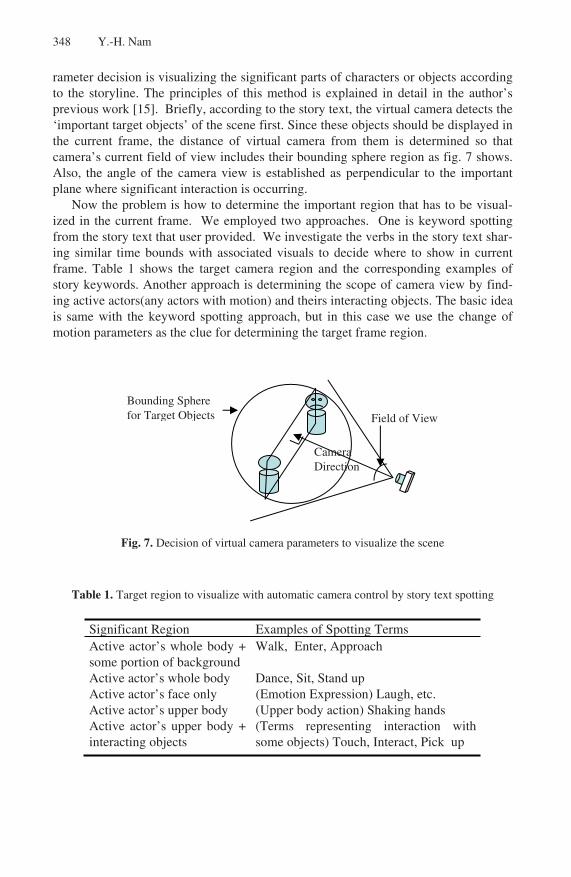
rameter decision is visualizing the significant parts of characters or objects according to the storyline. The principles of this method is explained in detail in the author’s previous work [15]. Briefly, according to the story text, the virtual camera detects the ‘important target objects’ of the scene first. Since these objects should be displayed in the current frame, the distance of virtual camera from them is determined so that camera’s current field of view includes their bounding sphere region as fig. 7 shows. Also, the angle of the camera view is established as perpendicular to the important plane where significant interaction is occurring.
Now the problem is how to determine the important region that has to be visual-ized in the current frame. We employed two approaches. One is keyword spotting from the story text that user provided. We investigate the verbs in the story text shar-ing similar time bounds with associated visuals to decide where to show in current frame. Table 1 shows the target camera region and the corresponding examples of story keywords. Another approach is determining the scope of camera view by find-ing active actors(any actors with motion) and theirs interacting objects. The basic idea is same with the keyword spotting approach, but in this case we use the change of motion parameters as the clue for determining the target frame region.
Fig. 7. Decision of virtual camera parameters to visualize the scene
Table 1. Target region to visualize with automatic camera control by story text spotting
Significant Region Examples of Spotting Terms Active actor’s whole body + some portion of background
Walk, Enter, Approach
Active actor’s whole body Dance, Sit, Stand up Active actor’s face only (Emotion Expression) Laugh, etc. Active actor’s upper body (Upper body action) Shaking hands Active actor’s upper body + interacting objects
(Terms representing interaction with some objects) Touch, Interact, Pick up
Bounding Sphere for Target Objects Field of View
Camera Direction

349
Fig. 8. Insertion of actors into a scene and generated shots by virtual camera animation
Fig. 8 shows several example frames created by camera animation. The initial frame of fig. 8’s first row shows the main actor standing in a position. In this scene, the virtual camera is zoomed out and visualizes the whole scene. Across time, the camera position is changed so that it can zoom the actor’s upper body region. Other images show scenes created by virtual camera animation in real-time.
5 Implementation: A Shared Story Building & Animation Tool
Based on the proposed method that makes user sketch into 3D-like scenes and charac-ters, we built up web-based shared storytelling system called DstoryOnline using Java applets and a server system. We also implemented using WildTangent library for the 3D graphics on the web.
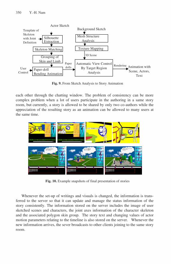
Fig. 9 summarizes all the major process for making sketches into an animation real-time. The input story text is attached to the generated visual frames according to the timeline specification of the text. It then switches over to the next group of text according to the change of scenes. In this manner, the story text and the visuals are unfolded simultaneously. The synchronization of text flow and the sequence of the scene play is based on the timeline specified at the authoring time. Fig. 10 shows some example snapshots extracted from a continuous animation sequences generated as the result of authoring.
Those who connect to the site can join one of currently opened story rooms. They can participate to a common authoring space. To avoid the consistency problem, there are user-levels with different authoring capabilities in a story room.
The user who opened a story room first becomes the main author and the next us-ers can only help and communicate with the main author. The users in a common story room cam share the visuals by selecting other user’s 3D view and authoring sketchbook. A user can help another user’s authoring process using helper’s tools that provide the functions of object pointing and text-based chatting. Users can communicate
Making User’s Sketch into a Motion Picture for Visual Storytelling on the Web
350 Y.-H. Nam
Fig. 9. From Sketch Analysis to Story Animation
each other through the chatting window. The problem of consistency can be more complex problem when a lot of users participate in the authoring in a same story room, but currently, a story is allowed to be shared by only two co-authors while the appreciation of the resulting story as an animation can be allowed to many users at the same time.
Fig. 10. Example snapshots of final presentation of stories
Whenever the set-up of writings and visuals is changed, the information is trans-ferred to the server so that it can update and manage the status information of the story consistently. The information stored on the server includes the image of user sketched scenes and characters, the joint axes information of the character skeleton and the associated polygon skin group. The story text and changing values of actor motion parameters relating to the timeline is also stored on the server. Whenever the new information arrives, the sever broadcasts to other clients joining to the same story room.
Grouping of Skin and Limb
Paper-doll Bending Animation
Skeleton Matching
Template of Skeleton with Joint Definition
Silhouette Extraction
Automatic View ControlBy Target Region
Analysis
Background Sketch
Mesh Structure Analysis
Texture Mapping
Paper dolls
3D Scene
Animation with Scene, Actors,
Text
RenderingUser
Control
Actor Sketch

351
6 Conclusions and Further Remarks
In summary, this paper describes an approach using sketch analysis and automatic view control to make it possible to simplify the process of visual story development and its presentation on the web. A web-based prototype system called DStoryOnline is constructed using Java to show the feasibility of the proposed methods. Since the scenes and objects are created based on user’s quick sketches, the resulting scenes can look rough but quite interesting because the objects are user’s personal creations. Finally, a story can be played as a motion-picture on the web, while attaching the corresponding story text across time. It is also verified experimentally that the real-time shared authoring is also possible at least by two people joining to the web.
This work is currently under extension to provide teacher’s tool to help story crea-tion of elementary school students. Based on our framework, the user interface for specifying motion parameters will be upgraded. Also, the keyword spotting mecha-nism will be more intensified by supplement the verb database.
References
1. Bolter, Joyce, Smith, Story Space, Computer Software, Cambridge MA: Eastgate Sys-tems (1992).
2. Kurlander, D., Skelly T., Slesin D., Comic Chat, Proceedings of SIGGRAPH’96, New Orleans, LA (1996), 1: 225–236.
3. Kim, K. R., Lim, C. Y., A Study on the narrative structure and interaction of the interac-tive movie, Human-Computer Interaction Workshop (2002), Phoenix Park, Korea, CD-1.
4. Horry, Y., Anjyo K., Arai K., Tour Into the Picture : Using a Spidery Mesh Interface to Make Animation from a Single Image, Proceedings of SIGGRAPH (1997), 1:225–232.
5. Kang, H., Pyo, S., Anjyo, K., Shin, S., TIP Using a Vanishing Line & Its Extension to Panoramic Images”, Eurographics (2001), Vol.20, No.3.
6. Beymer, D., Shashua, A., Poggio, T., Example based Image Analysis and Synthesis, AI Memo No. 1431, MIT (1993).
7. Kakadiaris, I., Metaxas, D., Bajcsy, R., Active Part- Decomposition, Shape and Motion Estimation of Articulated Objects: A Physics-based Approach, Proceedings Of the IEEE Computer Vision and Pattern Recognition, 1:980–994, Seattle, Washington, June (1994).
8. Agrawala, M., Beers, A., Chaddha, N., Model-based Motion Estimation for Synthetic Images, ACM Multimedia(1995).
9. Hearn, D., Baker, M. P. (ed.): Computer Graphics-C version, Prentice Hall (1997). 10. Zhang, T. Y., Suen, C.Y., A Fast Parallel Algorithm for Thinning Digital Patterns, Com-
munications of the ACM (1984) vol. 27, no. 3, pp 236–239. 11. Drucker, S. M., et al., CINEMA: A system for procedural camera movements, In: David
Zeltzer (eds.): Computer Graphics(Symposium on Interactive 3D Graphics) (1992) vol.25, pages 67–70.
12. Christianson, D.B., et al., Declarative Camera Control for Automatic Cinematography, In : Proceedings of the AAAI (1996).
13. Blinn, J., Where Am I? What Am I Looking At?, IEEE Computer Graphics and Applica-tions (1988) pages 76–81.
Making User’s Sketch into a Motion Picture for Visual Storytelling on the Web

352 Y.-H. Nam
14. He, Li-wei et al., The Virtual Cinematographer: A Paradigm for Automatic Real-Time Camera Control and Directing, In Computer Graphics (SIGGRAPH’96 Proceedings) (1996) pages 217–224, August 1996.
15. Nam, Y., Thalmann, D., CAIAS : Camera Agent based on Intelligent Action Spotting for Real-Time Participatory Animation in Virtual Stage, 5th International Conference on Vir-tual Systems and Multi-Media(VSMM), Scotland, UK (1999).