progress in nuclear energy - microfluidic foundry
TRANSCRIPT

lable at ScienceDirect
Progress in Nuclear Energy 88 (2016) 147e155
Contents lists avai
Progress in Nuclear Energy
journal homepage: www.elsevier .com/locate/pnucene
Modeling analyses of radioactive aerosol flow and collectionin mesoscopic impactor filters
Fenglei Niu a, Xiaochao Du a, Houbo Qi a, *, Mingqiang Yi b, Xu Yang a
a Beijing Key Laboratory of Passive Nuclear Power Safety and Technology, North China Electric Power University, Beijing 102206, Chinab Microfluidic Foundry L.L.C., San Pablo, CA 94806, USA
a r t i c l e i n f o
Article history:Received 3 June 2015Received in revised form28 December 2015Accepted 29 December 2015Available online xxx
Keywords:AerosolFilterMicrofluidMEMS inertial impactor
* Corresponding author.E-mail address: [email protected] (H. Qi).
http://dx.doi.org/10.1016/j.pnucene.2015.12.0100149-1970/© 2016 Elsevier Ltd. All rights reserved.
a b s t r a c t
The concentration of radioactive aerosols in the containment increases rapidly during the serious nuclearaccidents. The common aerosol filters use mesh structures or filter papers, which can significantly in-crease the flow resistance due to the aerosol deposition and retard the containment pressure relieffollowing the nuclear accidents. This paper proposes and studies a MEMS (Micro Electro MechanicalSystems) inertial impactor filters which can filtrate and collect 1 to 3 microns aerosol particles withoutfilter papers. It can significantly reduce the flow resistance in filtering micron-size aerosol particles. Themodeling method is given and the simulation results are analyzed.
© 2016 Elsevier Ltd. All rights reserved.
1. Introduction
When there is a rupture in the primary loop, the radioactiveaerosols under the thermal dynamic action would be rapidlyreleased into the internal environment, causing significant increaseof radioactive aerosols concentration in the containment vessels(Fischer and Kanzleiter,1999; Chen et al., 2011). It will cause seriousdamage to the atmospheric environment if such radioactive aero-sols are directly emitted (Yi et al., 1999). Therefore, it is necessary toattenuate the radioactive aerosols before release. Attempts havebeen made by the FCVS designs to reduce the emission of the mostpenetrating sized particles by incorporating different retentiontechniques as well as by utilization of fine aerosol filters. Thecommon filters collecting aerosols in nuclear power plants are FCVSwith water scrubbers e droplet separators/deep bed fine aerosolfilters, metal fiber filters with sorbent retention stage, sand bedfilters (OECD, 2014), high efficiency air filters, and activated carbonfilters (Allelein, 2009). Although these filters can collect and reducea certain amount of radioactive dust, the filter papers they used cansignificantly increase the flow resistance in the course of aerosoldeposition and therefore retard the containment pressure relief
following the nuclear accidents, moreover, replacement of filterpaper needs to be done regularly due to their mesh structure, and ithas been a technical problem under the highly radioactive condi-tion. In addition, the used filter papers become the new radioactivewastes (Arunkumar et al., 2007; Yu and Lin, 2011; Sun et al., 2012).The studies documented in this paper are concerned with a MEMS(Micro Electro Mechanical Systems) inertial impactor, which cancollect micron sized particles with no need of changing the filterpapers, and it can significantly reduce the flow resistance infiltering micron-size aerosol particles. MEMS belongs to the microdevice technology, which has many potential benefits, such as highperformance, low power consumption, good responsiveness, andlow cost. MEMS devices would be easier to isolate, clean, and reuse.As for practical application, there is much lower possibility for theMEMS inertial impactor than the common filters to get overloadedor chocked, because the diameter of the impactors' flow channels isbigger than the porous media. The impactor's collecting area can bedesigned to changeable parts depending on the needs ofapplication.
In recent years, MEMS technology has made lots of progress.According to the survey, there is no precedent to collect plantaerosols based on MEMS technology. This study of MEMS deviceaims at filtering and collecting aerosols within 1e3 microns, whichis a new attempt both on the design concept and technology.

Fig. 1. Inertial impactor model.
F. Niu et al. / Progress in Nuclear Energy 88 (2016) 147e155148
2. Filter model development
When a particle laden air stream is caused to change directionsuddenly, particles will tend to follow straight trajectories and toimpact the opposite wall. It has been witnessed that the heavier(bigger) particles impact while the smaller particles follow the airstream. Using this theory, we design a novel filter to collect theaerosol releases from nuclear power plant containments. Unlikecommon filters, this impactor system does not have the electropart. It uses particle inertia to achieve separation and collection,which is a passively screening system. Based on the inertial effectsin motion, the geometric model of MEMS inertial impactor formicron level aerosol collection was designed into a T tube with flatnozzle inlet, and the entrance width W is far less than its length.Therefore, a dimension in the direction of velocity can be neglectedbecause of this design, the fluid flow can be simplified to a two-dimensional flow (As shown in Fig. 1), and the flow field isassumed to not be affected by the existence of the particles. Wefirstly computed the 2-D flow field around a T-junction, then theparticles were seeded in the nozzle inlet and their trajectories werecomputed to determine whether they would impact or flow out.Our purpose is to find the optimized size that can achieve plantaerosol deposition based on the particle track.
Fig. 1 depicts the air streamlines and the particle trajectories inthe inertial impactor. In our theoretical studies, the particles' mo-tion equations in a known flow field were analyzed. The relativeimportance of the various forces exerted on the particles wasdetermined. An analytical criterion for determining whether theparticle would impact or flow out was also developed. Based on theflow field computed with the commercial code FLUENT, the cut-offparticle size was calculated as a function of the Reynolds numberand the impaction distance.
3. Particle motion equations and asymptotic analysis
The particles' motion is governed by Newton's second law (Yiet al., 1999), mass times acceleration equals to the force exertedon them. In the carrier flow field, the particles will experience theStokes drag force resulting from the relative velocity between theparticle and the fluid. Assuming sphere particle of diameter dp, theStokes drag force is 6prfvVrdp, in which Vr is the relative velocitybetween the particle and fluid.We also normalize the problemwithlength scale W, velocity scale U, and time scale U
W.The non-dimensional particles' motion equations are defined by Soo(1967) as below,
Stk2
d2x
dt2¼ u� dx
dt
Stk2
d2y
dt2¼ v� dy
dt
(3.1)
where (x, y) describe the instantaneous location of the particle attime t, and (u, v) are velocity of the flow field at point (x, y). Stk(Stokes number) is the normalized particle size, which is defined bySoo (1967) as following equation,
Stk ¼ Re9
rprf
þ 12
!�dpW
�2
(3.2)
Re ¼ uWg
(3.3)
In the above equation, rp is the particle density, dp is the particlediameter, u is the average inlet flow speed, W is the inlet nozzle
width, and g is the fluid kinematic viscosity. Stk is the ratio betweenthe particles' stopping distance in the quiescent fluid and the inletnozzle's width. The particles of large Stk will impact and can becollected while the particles of small Stk will flow out. Accountingfor the fact that an air mass moves with the particle, the stokesnumber is based on the apparent density that includes, in addition
to the particle's mass, the virtual air mass of�12
rfrp
�mp, where mp is
the particle mass.In order to design the impactor that is used for the plant aerosols
collection, we should find the relation among aerosol size, Re, andthe size of impactor. For each impactor design (D) and each flowfield (Re), we will seed each size (Stk) particle with the same speedas the fluid flow and then compute its trajectories inside theimpactor to determine whether it will be collected or flow out. Thefraction of collected particles is then calculated as the ratio ofcollected particles and total particles. By repeating the above cal-culations, we can obtain the fraction of collected particles (E) as afunction of the particle size (Stk), which is defined as the efficiencycurve of the inertial impactor.
Fig. 2 depicts the particle trajectories (dashed lines) and the flowstreamlines (solid lines). It is clear that the particle trajectoriesdeviate from the streamlines and the particles impact onto thebottom (impaction) plate. According to our simulations, no parti-cles impacted when
ffiffiffiffiffiffiffiStk
p� 1:08 and all particles impacted whenffiffiffiffiffiffiffi
Stkp
� 1:09.After a mass of simulating calculations, we can get the effi-
ciency curve as shown in Fig. 3, which reveals that the fraction ofthe collected particles (E) is a function of the particles' size for an“ideal” impactor with uniform inlet speed. That is, for the “ideal”impactor, particles that larger than a certain size (cut-off size) arecollected at the impaction plate while smaller particles flow out ofthe impactor. The cut-off size ð
ffiffiffiffiffiffiffiStk
p50Þ is defined as the size ð
ffiffiffiffiffiffiffiStk
pÞ
at which 50% of the particles are collected. In order to quantify the“sharpness” of the efficiency curve, we define a sharpness factorQE,
QE ¼Z0:950
��� ffiffiffiffiffiffiffiStkp
�ffiffiffiffiffiffiffiStk
p50
��� dE (3.4)
In an ideal impactor, QE¼ 0. The smaller the QE, the sharper theefficiency curve. In the definition of QE, the upper limit of the in-tegral was chosen as 0.95 instead of 1 to make the data morereasonable. This is due to the difficulty of computing the particletrajectories near thewall since the velocity is nearly zero. Moreover,in experiments, it is hard to obtain data for collection efficiencyclose to 1.

Fig. 2. Particle Trajectories (Dashed Lines) and Streamlines (Solid Lines) (Calculated using the Stokes Flow Field whenffiffiffiffiffiffiffiStk
p¼ 1 and
ffiffiffiffiffiffiffiStk
p¼ 1:1).
Fig. 3. Relation between the fraction of the collected particles (E) andffiffiffiffiffiffiffiStk
p.
F. Niu et al. / Progress in Nuclear Energy 88 (2016) 147e155 149
4. A criterion for determining the impaction of particles
4.1. Particle's requirements for the impaction
The performance of an impactor can be predicted by numericalmethods, which solve the equations governing the fluid flow andparticlemotion (Yi et al., 1999). Inmany cases, it is only necessary to
decide whether a particle could actually impact, given its positionand velocity components at a point sufficiently close to the plate. Insuch cases, an analytical criterion can be developed for determiningwhether a particle impacts without following through the inte-gration process until actual impact had occurred.
Our asymptotic solution for the flow field near the stagnationpoint suggests that the velocity decreases as a quadratic function ofy. A linearly decreasing flow field velocity would require anonphysical pressure singularity at the wall. Therefore, it's neces-sary to develop different criteria to judge whether a particle im-pacts or not. We assume the particle has vertical velocity v0 aty¼ y0, and the fluid's velocity is v1f at y¼D.
1) Simplest (most conservative collision criterion):
Considering equation (3.1) and neglecting the quadratic term,we obtain that, for the particle to arrive at the wall, it needs,
�v0 >2y0Stk
(4.1)
2) Results based on Stokes flow near the wall:
We assume fluid velocity of the form v ¼ v1f
�yD
�2, the collision
criterion is,

Fig. 4. (a): Relation between Reynolds Number and Cut-off Particle Diameterfor1000 mmWidth Nozzle. (b): Relation between Reynolds Number and Cut-off ParticleDiameter for100 mm Width Nozzle.
F. Niu et al. / Progress in Nuclear Energy 88 (2016) 147e155150
�v0 >2y0Stk
� 43Stk
v1fy30v0D2 ¼ 2y0
Stk
1� 2
3v1fy20v0D2
!(4.2)
3) When pressure effects are considered, the equation is,
Stk2
d2ydt2
¼ v1f
�yD
�2� dy
dt� 19
�dpW
�2v1fD2 (4.3)
Notice that additional work needs to be done to overcome thepressure gradient as the flow approaches the stagnation point.Therefore, a higher initial speed is needed for the particle to reachthe wall. The impaction criterion is,
�v0 >2y0Stk
"1� 2v1f y20
3v0D2 þ 2v1f9v0D2
�dpW
�2#
(4.4)
As we all know, the containment vessel pressure would increaserapidly when a serious accident takes place in nuclear powerplants, and the aerosol particles would also have a large instanta-neous speed, which is enough for the aerosol to crash into theMEMS inertial impactor filters. Therefore, all of the factors meet therequirements of being collected.
4.2. Calculations of particle's trajectories and collection efficiency
The trajectories of particles and collection efficiency are calcu-lated by the DPM model of the commercial code FLUENT, which isoften used to calculate the discrete phase model. The velocity ofparticles is modeled uniformly with the same as flow speed,considering particles are affected by gravity, Brownianmotion, dragforce, thermophoresis force, Saffman force, pressure gradient forceand buoyancy lift. If the particle was collected when it hit the floor,then the particle's trajectories in MEMS inertial impactor can betraced by numerical simulation, and the collected percentage isobtained.
5. Affecting factors analysis for the impactor's performance
In our study, the particles were assumed to be uniformlydistributed at the nozzle inlet. In conditions consistent with aserious nuclear plant accident, aerosol density is regarded as fuelcanning material which is 8030 times as dense as air. Next, we willdiscuss the specific relation between collection efficiency and Re, aswell as the relation between collection efficiency and thegeometrical size of MEMS inertial impactor filters.
5.1. The relation between Re and collection efficiency
For relatively high Reynolds numbers (Re > 500), Marple et al.(1974, 1987, 1991) and Marple and Liu (1975) computed perfor-mance curves for this type of an impactor. Here, we repeatedsimilar calculations for the low Reynolds numbers (Re < 500) thatare typical to mesoscopic impactor.
Fig. 4 shows the cut-off Stokes number, ðffiffiffiffiffiffiffiStk
pÞ50 (the normal-
ized critical cut-off particle diameter, ðdpÞ50=W) as a function of theReynolds number. As the Reynolds number increases, the cut-offparticle size decreases. The reason for this phenomenon is thatthe larger fluid inertia would cause the streamlines to get closer tothe impaction surface.
Fig. 5 schematically presents two streamlines originating at thesame point at the entrance under different Reynolds numbers(Re1> Re2). The smallest distance between the streamline and the
impaction surface is denoted as (s), which is the distance that theparticles need to cross in order for impact to occur. The larger theReynolds number, the smaller the s. The dependence of s on theReynolds number causes the dependence of the cut-off Stokesnumber on the Reynolds number. Furthermore, this dependencewas stronger for smaller Reynolds numbers. That means thedependence of the cut-off Stokes number on the Reynolds numberis stronger in mesoscopic impactor than in traditional ones.
5.2. The relation between filter geometrical size and collectionefficiency
In our simulations, particles were treated as spheres with finitediameter dp, not a point. Since the dependence of the cut-off size onthe Reynolds number decreases as the Reynolds number increases,it is desirable to operate the impactor at as high a Reynoldsnumbers as possible to minimize its sensitivity to fluctuations inthe flow rate. Unfortunately, high Reynolds number operation isdifficult to achieve in a mesoscopic impactor. By reducing theimpaction distance, one can reduce the dependence of the cut-off

Fig. 5. Effects of the Reynolds number on streamlines and the distances (Re1> Re2).
Fig. 7. (a) Efficiency curves (Y/W¼ T/W ¼ 1). (b) Efficiency curves (Y/W ¼ 1/2 and T/W ¼ 1).
F. Niu et al. / Progress in Nuclear Energy 88 (2016) 147e155 151
size on the Reynolds number. For example, when Y/W ¼ 1/2, thedependence of the cut-off size on the Reynolds number is weakerthan when Y/W ¼ 1.
The effect of the impaction distance on the cut-off Stokesnumber is illustrated in Fig. 6. As the impact distance (Y) increases,the
ffiffiffiffiffiffiffiStk
pincreases nearly linearly when Re ¼ 10. As shown in Fig. 5,
the distance required for the particle to impact (s) is proportional tothe impaction distance when the pattern of the streamlineschanges in proportion to the impaction distance. Since the Stokesnumber is the particle's stopping distance, this means that the cut-off particle size also changes in proportion to the impaction dis-tance. This dependence would flatten out when s does not varywith the impaction distance any more. After the simulation calcu-lation, we obtained the relation between geometrical size Y/W andcollection efficiency as shown in Fig. 7.
Fig. 7a and b shows the efficiency curves when Y/W¼ 1 (G1) andY/W¼ 1/2 (G2), respectively. r�p ¼ 1000 and Re¼ 1, 5, 10, 20, 50, 80.It indicated that when Y/W ¼ 1/2, the dependence of efficiencycurve on inlet velocity profile and the Reynolds number was
Fig. 6. Cut-off particle size as a function of the impaction distances, Re ¼ 10.
weaker than when Y/W ¼ 1. In addition, the efficiency curves weresharper than that of Y/W ¼ 1/2.
6. Design and validation of MEMS inertial impactor filter
6.1. Filter design and simulation model establishment
Based on the analysis above and the environmental condition ofcontainment under a serious accident, we can design the filter sizeand have it meet filtering requirements. Though the aerosol ismixture which contained a huge range of materials and chemicalcompounds, the density of the fuel cladding material is muchhigher than any other compounds of aerosols, and makes up a largepercent of the mixture, so fuel cladding material has the mostimportant influence in the aerosols. Therefore, the density of thefuel cladding material (alloy material particles) whose density is8030 times of air was used for the computation purpose in oursimulation. Moreover, we supposed the particle size is 2 mm (OECD,2014), designed the temperature as 150 �C (Lin, 2008). In the nu-merical simulation, the inlet pressure of gas phase and particleswas designed as 0.407 MPa (Lin, 2008), considering particles underthe force of gravity, Brownian motion, drag force, thermophoresisforce, Saffman force and pressure gradient force.
According to the analysis, the diameter of T tube would be smallenough to meet the condition of small Reynolds number. In oursimulation, the inlet diameter of T tube was designed asW¼ 1mm,outlet diameter Y ¼ 0.5 mm, and height T ¼ 1 mm. In order toensure the particle's collision distance, we designed a long bottomof the collection plate with 13 mm.
In this paper, we set up inertial impact model using the abovedimensions. NaviereStokes equation and Continuity equation wasbuilt and solved by using the commercial code FLUENT for thesimulation of flow field in T impactor. In computing, we assumedthat the fluid inlet velocity is 6 m/s according to the nuclear powerplant accident conditions.
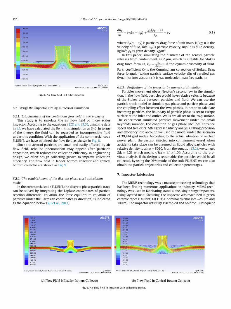
Fig. 8. Air flow field in T tube impactor.
F. Niu et al. / Progress in Nuclear Energy 88 (2016) 147e155152
6.2. Verify the impactor size by numerical simulation
6.2.1. Establishment of the continuous flow field in the impactorThis study is to simulate the air flow field of micro scales
impactor. According to the equations (3.2) and (3.3), using the datain 6.1, we have calculated the Re in this simulation as 340. In termsof the theory, the fluid can be regarded as incompressible fluidunder this condition. With the application of the commercial codeFLUENT, we have obtained the flow field as shown in Fig. 8.
Since the aerosol particles are small and easily affected by airflow field, rebound phenomenon may appear after particle'sdeposition, which reduces the collection efficiency. In engineeringdesign, we often design collecting groove to improve collectionefficiency. The flow field in ladder bottom collector and conicalbottom collector are shown as Fig. 9.
6.2.2. The establishment of the discrete phase track calculationmodel
In the commercial code FLUENT, the discrete phase particle trackcan be solved by integrating the Laplace coordinates of particlereaction differential equation, the force equilibrium equation ofparticles under the Cartesian coordinates (x direction) is indicatedas the equation below (Ru et al., 2013).
Fig. 9. Air flow field in impact
dupdt
¼ FD�u� up
þ gx�rp � r
rp
þ Fx (6.1)
where FD(u � up) is particles' drag force of unit mass, N/kg; u is thevelocity of fluid, m/s; up is particle velocity, m/s; r is fluid density,kg/m3; rp is grain density, kg/m3.
In this paper, simulating the diameter of the aerosol particlereleases from containment as 2 mm, which is suitable for Stokes
drag force formula, FD ¼ 18md2prpCc
.m is the dynamic viscosity of fluid,
Pa s; coefficient CC is the Cunningham correction of Stokes. Dragforce formula (taking particle surface velocity slip of rarefied gasdynamics into account), l is gas molecule mean free path, m.
6.2.3. Verification of the impactor by numerical simulationParticles movement obeys Newton's second law in the simula-
tion. In the flow field, particles would have relative velocity becauseof the Stokes drag between particles and fluid. We can use theparticle track model to simulate gas phase and particle phase, andthe coupling effect between the two phases. In order to calculateincoming particles, the boundary of particle phase is set to escapesurface at the inlet and outlet. Walls are all set to the trap surface.The experiment simulated particles movement under the smallReynolds number. The condition of gas phase includes entrancespeed and free exits. After grid sensitivity analysis, taking precisionand efficiency into account, we used the model under the scenarioof 39,414 grid nodes. According to the actual situation of nuclearpower plant, the aerosol injected into containment vessel whenaccidents take place can be assumed as liquid alloy particles withrelative density to air, r¼ 8030. From the equation (3.2), we can getStk ¼ 1.21 which means
ffiffiffiffiffiffiffiStk
p¼ 1:1>1:09. According to the pre-
vious analysis, if the design is reasonable, the particles would be allcollected. By using the DPMmodel of the code FLUENT, we can alsoobtain the particle trajectories and collection percentages.
7. Impactor fabrication
The MEMS technology was a mature processing technology thathas been finding numerous applications in industry. MEMS tech-nology was used in fabricating stand-alone, single stage impactors.Using layered manufacturing, the impactor was machined in greenceramic tapes (DuPont, LTCC 951, nominal thicknesses ~250 m and100m). The impactor was fully assembled and co-fired. Subsequent
or with collecting groove.

Fig. 10. Cross-section of the mesoscopic impactor fabricated in seven layers of ceramictapes.
F. Niu et al. / Progress in Nuclear Energy 88 (2016) 147e155 153
to the machining, internal cavities were filled with a graph-iteeorganic binder mixture to prevent process-induced de-formations, the layers were stacked together, laminated, and co-fired (Bau et al., 1998). During the firing process, the organicbinder burnt out and alumina particles and the glass sintered toform a rigid, monolithic block with internal fluidic passages. Fig. 10depicts a cross-section of an impactor made out of 7 layers (fromtop to bottom) of ceramic tapes. Layers 1e3 contain the nozzle;layers 4e6 house the impactor's cavity and layer 7 houses the exitports (Each layer is about 230 m thick after firing, and the nozzle
Fig. 11. Photographs of an impactor fabricated in ceramic tapes.
Fig. 12. Real object of impactor.
size (the top slot) is about 5 mm*500 m). Fig. 11a and Fig. 11brespectively show photographs of the top and bottom views of animpactor. Fig. 11c is an image of a diced impactor's cross-section.The slot shown in Fig. 11a is the entrance to the intake nozzle.The two slots on the bottom serve to exhaust the gas stream. Thegas streamwas drawn through the impactor by inducing a vacuumdownstream of the device.
The real object of impactor was shown in Fig. 12, inside therubber is a real T-end impactor, inlet on the side of the siliconsurface while two exports on the border of silicon and rubber.
We note in passing that a few impactors can be connected inparallel to accommodate high flow rates. Furthermore, a number ofimpactors can be connected in series to form a multi-stageimpactor that makes the aerosols inside the containment to becollected efficiently.
8. Conclusions
In the process of numerical simulation, setting temperature for150 �C and pressure for 0.407 MPa based on the nuclear powerplant accident situation. We supposed that the particles rush into Ttubewith uniform speed as the same value of flow field. Figs.13 and14 show the particle track and the percentage of particle collection,respectively.
Simulating the same process, particle tracks in two impactorswith different collecting groove were obtained and shown asFig. 15.

Fig. 14. Collection percentage of particles (data screenshot).
Fig. 13. Particles trajectories in T tube.
Fig. 15. Particle trajectories in impactor with collecting groove. (For interpretation of the references to color in this figure legend, the reader is referred to the web version of thisarticle.)
F. Niu et al. / Progress in Nuclear Energy 88 (2016) 147e155154
(1) From results shown in Figs. 13e15, it indicates that all theaerosols were collected in the MEMS inertial impactor filter,which proves that the size of impactor is reasonable, and thetheory we put forward is feasible. It also proves that usingMEMS inertial impactor filter to collect aerosol in contain-ment vessel is feasible. Besides, collecting groove canimprove the collection efficiency. Since the collected speed ofthe particles was reduced by collecting groove (particle'speed in figure orderly increased from color blue to red), thepossibility of rebound was also reduced. It can be demon-strated in Fig. 15, ladder bottom collector has larger bluecollected area than conical bottom collector, so it become abetter choice for aerosol collection, the design of collecting
groove has a certain value in practical engineeringapplication.
(2) From the simulation results analysis, it demonstrated thatparticles in MEMS inertial impactor filter were attenuatedquickly, so the length of the bottom plate is long enough forthe good collection efficiency.
(3) MEMS inertial impactor filter has many advantages, such asminiaturization, low cost, high precision and good dynamiccharacteristics, which made it applicable for the specialenvironment of nuclear power plant containment vessel. Inpractice, it can be arranged in series in containment vessel toincrease the filtering efficiency. The concept that usingMEMS inertial impactor filter to attenuatemicron radioactiveaerosols is feasible and has practical significance.
It would cause serious pollution if the radioactive aerosols ofcontainment vessels were released into the air without filtering.How to collect and attenuate with a simple and effective methodhas always been a problem. Based on the analysis and demon-stration in this paper, application of MEMS Inertial impactor filterto attenuate and filtrate aerosol in containment vessel under theaccident cases of nuclear power plant is feasible. If this method isapplied successfully, it will make up for the deficiencies of existingaerosol filtration method, and become an innovative method foraerosols attenuation which will prevent the radioactive aerosolsfrom escaping effectively.
This paper does not discuss the influence of radioactivity onparticle transport phenomena. Radioactive particles can heat upthe surrounding gas which will change the gas properties and, in
consequence, change the transport phenomena. In the furthersimulation we will consider its effects. Moreover, in order to getmore reasonable results, in the future work when we calculate forthe condition of the mixture aerosols, we will use the aerodynamicdiameter to consider the effects of internal voids and agglomerates.
Acknowledgments
This research is supported by the National Natural ScienceFoundation of China (91326108) and the Reactor System DesignTechnology Laboratory (HT-A100K-02-2014007).

F. Niu et al. / Progress in Nuclear Energy 88 (2016) 147e155 155
References
Arunkumar, R., Hogancamp, Kristina U., Parsons, Michael S., et al., 2007. High-ef-ficiency particulate afilter test stand and aerosol generator for particle loadingstudies. Rev. Sci. Instrum. 78 (8).
Bau, Haim H., Ananthasuresh, Suresh G.K., Santiago-Aviles, Jorge J., et al., 1998.Ceramic tape-based MESO systems technology. In: 1998 ASME InternationalMechanical Engineering Congress and Exposition (IMECE'98), pp. 491e498.
Chen, X.L., Wang, Y.Y., Xiong, Q.F., et al., 2011. The incident particle simulation basedon the radioactive aerosol detector of nuclear power plant. Mar. Sci. Technol.Press 33 (8), 53e57.
Fischer, K., Kanzleiter, T., 1999. Experiments and computational models for aerosolbehavior in the containment. Nucl. Eng. Des. 191 (1), 53e67.
Allelein, Hans-Josef, 2009. State of the Art Report on Nuclear Aerosol SNEA. CSNI/R,p. 5.
Lin, C.G., August 1st, 2008. AP1000 System and Equipment. Version 1. Atomic En-ergy Press, pp. 192e193.
Marple, V.A., Liu, B.Y.H., 1975. On fluid flow and aerosol impaction in inertialimpactor. J. Colloid Interface Sci. 53, 31e34.
Marple, V.A., Liu, B.Y.H., Whitby, K.T., 1974, Dec. On the flow fields of inertialimpactor. J. Fluids Eng. 394e400.
Marple, V.A., Rubow, K.L., Turner, W., Spengler, J.D., 1987. Low flow rate sharp cutimpactor for indoor air sampling: design and calibration. J. Air Pollut. ControlAssoc. 37, 1303e1307.
Marple, V.A., Rubow, K.L., Behm, S.M., 1991. A microorfice uniform deposit impactor(MOUDI): description, calibration, and use. Aerosol Sci. Technol. 14, 434e446.
OECD, 2014. Status Report on Filtered Containment Venting, 7. NEA/CSNI/R,pp. 71e74.
Ru, X.L., Zhou, T., Lin, D.P., et al., 2013. The numerical simulation and comparativestudy on two kinds of section within the narrow channel which PM1 particledeposit on. Nucl. Power Eng. Press 34 (z1), 42e46.
Soo, S.L., 1967. Fluid Dynamics of Multiphase Systems. Blaisdell PublishingCompany.
Sun, X.T., Ji, S.T., Liu, Z.H., et al., 2012. The research on aerosol behavior in nuclearfuel cycle critical accident. At. Energy Sci. Technol. Press 46 (z1), 314e319.
Yi, M.Q., Hu, H.H., Bau, H.H., 1999. Theoretical and experimental study of meso-scopic impactors. In: IMECE 1999 MEMS 1999 Symposium Proceedings. MEMS-Vol. 1, pp. 517e522.
Yu, L.T., Lin, Y.Q., 2011. The Experience Feedback and Analysis of Air PurificationSystem in Nuclear Power Plant, China's Nuclear Science and Technology Prog-ress Report (The second volume), Nuclear Power Volume Classification (top), 10.