programming with bluespec systemverilog: design methodologies
TRANSCRIPT

Programming with Bluespec SystemVerilog:
Design Methodologies, Styles, Patterns and Examples
Preliminary Draft
Please do not circulate without permission from Bluespec, Inc.
Revision: 24 November 2008
Copyright c© 2000 – 2008 Bluespec, Inc.
This document describes Bluespec SystemVerilog coding guidelines though a series of descriptions andexamples, where the objectives are to:
• bring experienced Verilog and VHDL designers up to speed with the abilities and features of Bluespec,• produce expected RTL with respect to interfaces, and structures,• take advantage of the extensive libraries provided by Bluespec.
This document is organized into several sections which need not be read in sequence. Rather, each sectiongives hints, advice and examples on particular design or programming structures.
This document is not intended to replace the Reference Guide or the User’s guide. It is a intended only asa supplement to aid designers in expressing their designs in the Bluespec environment.
This document is under development.
1

Contents
Table of Contents 2
1 Types 4
1.1 Bit Types . . . . . . . . . . . . . . . . . . . . . . . . . . . . . . . . . . . . . . . . . . . . . . 4
1.2 Non Bit Types . . . . . . . . . . . . . . . . . . . . . . . . . . . . . . . . . . . . . . . . . . . 4
1.3 Conversion Between Types . . . . . . . . . . . . . . . . . . . . . . . . . . . . . . . . . . . . 4
1.4 Types from the Bluespec Library . . . . . . . . . . . . . . . . . . . . . . . . . . . . . . . . . 5
2 Designing Interfaces 8
2.1 Interface Basics . . . . . . . . . . . . . . . . . . . . . . . . . . . . . . . . . . . . . . . . . . . 8
2.2 Sharing Signals in an Interface . . . . . . . . . . . . . . . . . . . . . . . . . . . . . . . . . . 9
2.3 Combining Interfaces . . . . . . . . . . . . . . . . . . . . . . . . . . . . . . . . . . . . . . . . 10
2.4 Basic Interfaces from the Bluespec Library . . . . . . . . . . . . . . . . . . . . . . . . . . . . 10
2.5 Interface Paradigms from the Library . . . . . . . . . . . . . . . . . . . . . . . . . . . . . . 11
3 Logic Representation 12
3.1 Sequential Element . . . . . . . . . . . . . . . . . . . . . . . . . . . . . . . . . . . . . . . . . 12
3.2 Combinational Logic . . . . . . . . . . . . . . . . . . . . . . . . . . . . . . . . . . . . . . . . 12
4 System Design Examples 13
4.1 Synchronous State Machine . . . . . . . . . . . . . . . . . . . . . . . . . . . . . . . . . . . . 13
4.2 Defining Interface Methods . . . . . . . . . . . . . . . . . . . . . . . . . . . . . . . . . . . . 15
4.3 Extracting pieces from an interface . . . . . . . . . . . . . . . . . . . . . . . . . . . . . . . . 16
4.4 Using RWire to Avoid Registers and Latency . . . . . . . . . . . . . . . . . . . . . . . . . . 16
5 Testbenches 18
5.1 Controlling Simulation . . . . . . . . . . . . . . . . . . . . . . . . . . . . . . . . . . . . . . . 18
5.2 Stored Test Patterns . . . . . . . . . . . . . . . . . . . . . . . . . . . . . . . . . . . . . . . . 19
5.3 Generating Random Test Patterns . . . . . . . . . . . . . . . . . . . . . . . . . . . . . . . . 19
6 Common Hints and Style Suggestions 21
6.1 Identifier Names . . . . . . . . . . . . . . . . . . . . . . . . . . . . . . . . . . . . . . . . . . 21
6.2 Use let Variables . . . . . . . . . . . . . . . . . . . . . . . . . . . . . . . . . . . . . . . . . . 21
6.3 Using types instead of ‘defines . . . . . . . . . . . . . . . . . . . . . . . . . . . . . . . . . . . 21
6.4 Adding Monitors . . . . . . . . . . . . . . . . . . . . . . . . . . . . . . . . . . . . . . . . . . 22
2

7 Helping the Scheduler 23
7.1 Rules versus Always Blocks . . . . . . . . . . . . . . . . . . . . . . . . . . . . . . . . . . . . 23
7.2 Alleviating Read/Write Conflicts with ConfigReg . . . . . . . . . . . . . . . . . . . . . . . . 24
7.3 Register Updates . . . . . . . . . . . . . . . . . . . . . . . . . . . . . . . . . . . . . . . . . . 24
8 Debugging Hints and Tips 26
8.1 Viewing Complex Data Structures . . . . . . . . . . . . . . . . . . . . . . . . . . . . . . . . 26
9 BlueSim 29
9.1 Improving Simulation Speed . . . . . . . . . . . . . . . . . . . . . . . . . . . . . . . . . . . . 29
10 Other Notes 30
10.1 Using Bluespec with other tools . . . . . . . . . . . . . . . . . . . . . . . . . . . . . . . . . . 30
11 Using Existing Verilog Components in a BSV Design 31
11.1 Sample Verilog Memory Import . . . . . . . . . . . . . . . . . . . . . . . . . . . . . . . . . . 31
3

1 Types
Bluespec provides a strong, static type-checking environment. Everything has a type; that is, every variableand every expression has a type. Variables must be assigned values which have compatible types. Typechecking, which occurs before program elaboration or execution, ensures that object types are compatibleand that needed conversion functions are valid for the context.
This section describes common types and structures as defined and used in the Bluespec environment.
1.1 Bit Types
At the lowest level, synthesizable objects can be considered as a wire or wires having some fixed widthand interpretation. These correspond to Verilog wire and reg, and additionally have tighter semanticssurrounding their use.
• Bool is a Boolean – a True or False value. The implementation is one bit, but bit-wise operations onBooleans in Bluespec are illegal. Booleans should be used for True or False values; Bit#(1) should beused for zero or one variables.)• Bit#(n) defines a type containing n bits. Type Bit allows bit-wise operations, but Bit#(1) cannot be
used as a Bool; that is, operators &&, ||, and ! are not allowed. Use Bit#(n) types for variables whichare simple bit patterns. Note: bit[15:0] is a synonym for Bit#(16).• UInt#(n) defines an unsigned integer of n bits in width. Use UInt#(n) for variables which should be
interpreted as unsigned quantities. Note: unsigned variables are always greater than or equal to zero.• Int#(n) defines a signed (two’s-complement) integer of width n. Use Int#(n) for variables which should
be interpreted as signed quantities.
These bit type can be combined into other types through the use of user defined structures or by using themany pre-defined types in the Bluespec library. (See Reference Manual for details of the documentation.)
1.2 Non Bit Types
In addition to the many bit types found in Bluespec, there are many other types which are only used duringcompile-time evaluation, and cannot be turned into hardware bits. These types are most useful duringcompile time elaboration, where Bluespec allows the manipulation of objects of these types for complicatedand highly parameterized designs.
• Integer – Integers are unbounded in size which are commonly used as loop indices for compile-timeevaluation.• String – Strings must be resolved at compile time.• Interfaces – Interfaces can be considered a type, and hence can be passed to or returned from functions.• Action – See Reference Manual for functions which manipulate this type.• ActionValue – See Reference Manual for functions which manipulate this type.• Rules – See Reference Manual for functions which manipulate this type.• Modules – See Reference Manual for functions which manipulate this type.• functions – Functions are first class objects and can be passed to other functions or modules.
1.3 Conversion Between Types
The Bluespec environment strictly checks both bit-width compatibility and type. This behavior differs fromtypical Verilog tools in that conversion is automatic in Verilog tools, whereas Bluespec requires explicit
4

conversions. To convert across types in Bluespec, the following overloaded functions should suffice. Duringtype checking, the compiler resolves these functions to a particular type instance. Excessive type conversionusually indicates a poor choice of the basic object types used in the design.
• pack() – converts (packs) from various types, including Bool, Int, and UInt to Bit#(n).• unpack() – converts to various types, including Bool, Int, and UInt from Bit#(n).• zeroExtend() – increases the bit width of an expression by padding the most significant end with zeros.
This function and the following two are overloaded in type Bit, UInt, and Int.• signExtend() – increases the bit width of an expression by replicating the most significant bit.• truncate() – shortens the bit width to a particular width.• fromInteger – Converts from an Integer to any type where this function is provided in the Literal type-
class. Integers are most often used during static elaboration since they cannot be turned into bit, hencethere is no corresponding toInteger function.• valueOf – Converts from a numeric type to an Integer. Numeric types are the “n’s” as used in Bit#(n)
or the number 17 as used in Bit#(17).
These conversion utilities do not incur logic overhead. The following example shows these type conversionfunctions in use.
...
Bit#(1) aB1;
Bool aBool = unpack( aB1 ) ; // unpack from Bit
...
Bit#(16) aB16 ;
Int#(16) aI16 = unpack( aB16 ); // size matters
...
Bit#(16) bB16 ;
bB16 = pack( aI16 ) ; // convert back to bits
...
// Truncates and Extends do not require any bit width information
UInt#(16) aU16;
UInt#(14) aU14 = truncate ( aU16 ) ;
...
Bit#(16) aB16;
Bit#(14) aB1 = truncate ( aB16 ) ;
...
// Extending requires same base type
Int#(14) aI14 ;
Int#(16) aI16 = signExtend( aI14 ) ;
UInt#(14) aU14 ;
UInt#(16) aU16 = signExtend( aU14 ) ;
Bit#(14) aB14 ;
Bit#(16) aB16 = zeroExtend( aB14 ) ;
...
// UInt to Int 16 conversion using pack and unpack
UInt#(16) aU16 ;
Int#(16) aI16 = unpack( pack ( aU16 ) ) ;
1.4 Types from the Bluespec Library
The Bluespec environment provides many abstractions and polymorphic data types in its library. A fewcommon ones are detailed here, since they have high correlation to common (hardware) design paradigms.
5
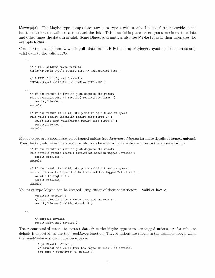
Maybe#(a) The Maybe type encapsulates any data type a with a valid bit and further provides somefunctions to test the valid bit and extract the data. This is useful in places where you sometimes store dataand other times the data in invalid. Some Bluespec primitives also use Maybe types in their interfaces, forexample RWire.
Consider the example below which pulls data from a FIFO holding Maybe#(a type), and then sends onlyvalid data to the valid FIFO.
...
// A FIFO holding Maybe results
FIFO#(Maybe#(a_type)) result_fifo <- mkSizedFIFO (16) ;
// A FIFO for only valid results
FIFO#(a_type) valid_fifo <- mkSizedFIFO (16) ;
...
// If the result is invalid just dequeue the result
rule invalid_result (! isValid( result_fifo.first )) ;
result_fifo.deq ;
endrule
// If the result is valid, strip the valid bit and re-queue.
rule valid_result (isValid( result_fifo.first )) ;
valid_fifo.enq( validValue( result_fifo.first )) ;
result_fifo.deq ;
endrule
Maybe types are a specialization of tagged unions (see Reference Manual for more details of tagged unions).Thus the tagged-union “matches” operator can be utilized to rewrite the rules in the above example.
// If the result is invalid just dequeue the result
rule invalid_result (result_fifo.first matches tagged Invalid) ;
result_fifo.deq ;
endrule
// If the result is valid, strip the valid bit and re-queue.
rule valid_result ( result_fifo.first matches tagged Valid{.x} ) ;
valid_fifo.enq( x ) ;
result_fifo.deq ;
endrule
Values of type Maybe can be created using either of their constructors – Valid or Invalid.Results_t aResult ;
// wrap aResult into a Maybe type and enqueue it.
result_fifo.enq( Valid( aResult ) ) ;
...
// Enqueue Invalid
result_fifo.enq( Invalid ) ;
The recommended means to extract data from the Maybe type is to use tagged unions, or if a value ordefault is expected, to use the fromMaybe function. Tagged unions are shown in the example above, whilethe fromMaybe is show in the code below.
Maybe#(int) mValue ;
// Extract the value from the Maybe or else 0 if invalid.
int extr = fromMaybe( 0, mValue ) ;
6
The above code fragment is equivalent to:
Maybe#(int) mValue ;
int extr = 0 ;
if ( isValid( mValue ) )
extr = validValue( mValue ) ;
The former is recommended.
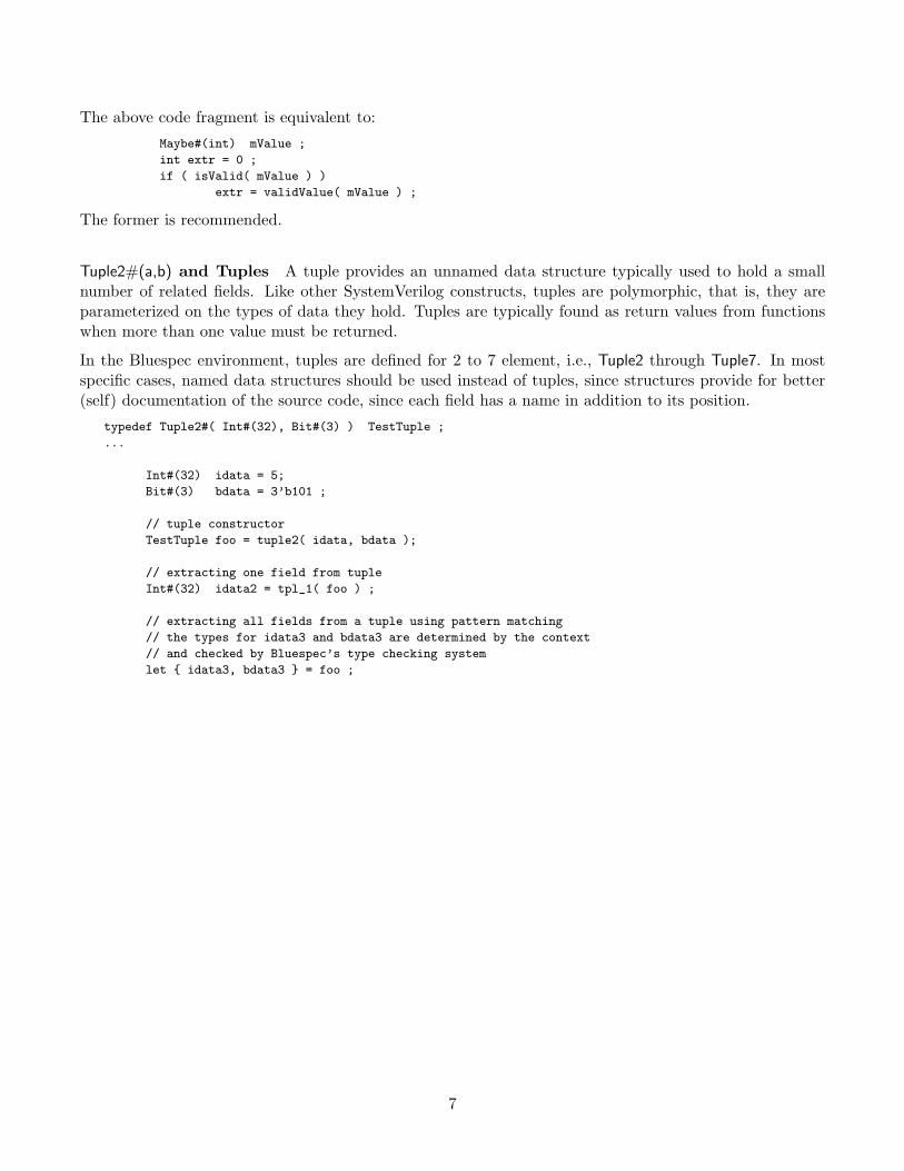
Tuple2#(a,b) and Tuples A tuple provides an unnamed data structure typically used to hold a smallnumber of related fields. Like other SystemVerilog constructs, tuples are polymorphic, that is, they areparameterized on the types of data they hold. Tuples are typically found as return values from functionswhen more than one value must be returned.
In the Bluespec environment, tuples are defined for 2 to 7 element, i.e., Tuple2 through Tuple7. In mostspecific cases, named data structures should be used instead of tuples, since structures provide for better(self) documentation of the source code, since each field has a name in addition to its position.
typedef Tuple2#( Int#(32), Bit#(3) ) TestTuple ;
...
Int#(32) idata = 5;
Bit#(3) bdata = 3’b101 ;
// tuple constructor
TestTuple foo = tuple2( idata, bdata );
// extracting one field from tuple
Int#(32) idata2 = tpl_1( foo ) ;
// extracting all fields from a tuple using pattern matching
// the types for idata3 and bdata3 are determined by the context
// and checked by Bluespec’s type checking system
let { idata3, bdata3 } = foo ;
7
2 Designing Interfaces
This section presents an overview of interfaces as they are used with Bluespec SystemVerilog. This sectionfocuses on defining interfaces, and does not detail how methods can be defined. See Section 4.2 for detailsand examples of defining methods, since many implementations can provide the same interface.
2.1 Interface Basics
In Verilog interfaces for modules are port lists; conceptually a bundle of independent of wires whichconnect the module to its parent. SystemVerilog extends the port list concept by providing interfaceswhich encapsulate interconnect and communication thus separating communication from functionality andenabling abstraction in the design.
SystemVerilog interfaces have many similarity to Verilog modules in that interfaces must be defined andinstantiated before use. Moreover, interfaces or modules can provide tasks and functions to further encap-sulate communication between modules.
In the Bluespec environment, interfaces to modules are methods, that is, specific functions which may beinvoked by the caller. These functions may take zero or more arguments, can return values or cause actionsto occur. Bluespec interfaces provide a means to group wires into bundles with specified uses.
Bluespec classifies methods into types:
• Value Methods – These are methods which return a value to the caller. When these methods are called,there is no change of state.• Action Methods – These are methods which cause actions (state changes) to occur. One may consider
these as input methods, since they typically take data into the module.• ActionValue Methods - These methods couple Action and Value methods, providing an action to the
module which provided the method, and returning a value to the caller.
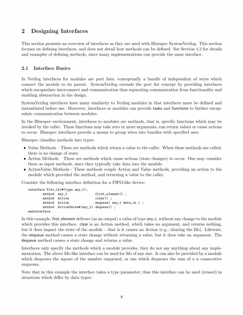
Consider the following interface definition for a FIFO-like device:
interface Fifo_ifc#(type any_t);
method any_t first_element() ;
method Action clear() ;
method Action enqueue( any_t data_in ) ;
method ActionValue#(any_t) dequeue() ;
endinterface
In this example, first element delivers (as an output) a value of type any t, without any change to the modulewhich provides this interface. clear is an Action method, which takes no argument, and returns nothing,but it does impact the state of the module – that is it causes an Action (e.g., clearing the fifo). Likewise,the enqueue method causes a state change without returning a value, but it does take an argument. Thedequeue method causes a state change and returns a value.
Interfaces only specify the methods which a module provides, they do not say anything about any imple-mentation. The above fifo-like interface can be used for fifo of any size. It can also be provided by a modulewhich dequeues the square of the number enqueued, or one which dequeues the sum of a n consecutiveenqueues.
Note that in this example the interface takes a type parameter; thus this interface can be used (reused) insituations which differ by data types:
8
// declaring a module with an interface of Fifo_ifc
module mkFifo1( Fifo_ifc#(any_t) ) ;
...
endmodule
...
// instantiate a interface with a specific type Bit#(32)
Fifo_ifc#(Bit#(32)) fifo32_inst1 <- mkFifo1 ;
...
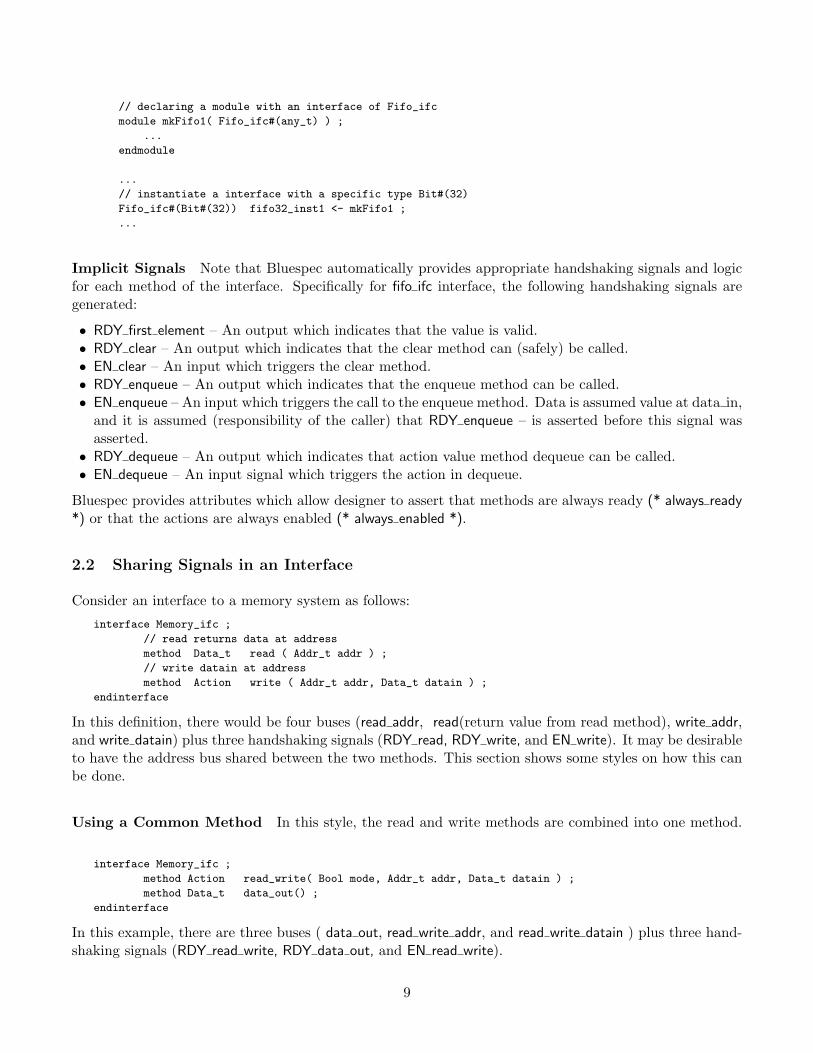
Implicit Signals Note that Bluespec automatically provides appropriate handshaking signals and logicfor each method of the interface. Specifically for fifo ifc interface, the following handshaking signals aregenerated:
• RDY first element – An output which indicates that the value is valid.• RDY clear – An output which indicates that the clear method can (safely) be called.• EN clear – An input which triggers the clear method.• RDY enqueue – An output which indicates that the enqueue method can be called.• EN enqueue – An input which triggers the call to the enqueue method. Data is assumed value at data in,
and it is assumed (responsibility of the caller) that RDY enqueue – is asserted before this signal wasasserted.• RDY dequeue – An output which indicates that action value method dequeue can be called.• EN dequeue – An input signal which triggers the action in dequeue.
Bluespec provides attributes which allow designer to assert that methods are always ready (* always ready*) or that the actions are always enabled (* always enabled *).
2.2 Sharing Signals in an Interface
Consider an interface to a memory system as follows:
interface Memory_ifc ;
// read returns data at address
method Data_t read ( Addr_t addr ) ;
// write datain at address
method Action write ( Addr_t addr, Data_t datain ) ;
endinterface
In this definition, there would be four buses (read addr, read(return value from read method), write addr,and write datain) plus three handshaking signals (RDY read, RDY write, and EN write). It may be desirableto have the address bus shared between the two methods. This section shows some styles on how this canbe done.
Using a Common Method In this style, the read and write methods are combined into one method.
interface Memory_ifc ;
method Action read_write( Bool mode, Addr_t addr, Data_t datain ) ;
method Data_t data_out() ;
endinterface
In this example, there are three buses ( data out, read write addr, and read write datain ) plus three hand-shaking signals (RDY read write, RDY data out, and EN read write).
9
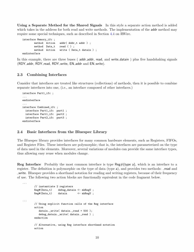
Using a Separate Method for the Shared Signals In this style a separate action method is addedwhich takes in the address for both read and write methods. The implementation of the addr method mayrequire some special techniques, such as described in Section 4.4 on RWire.
interface Memory_ifc ;
method Action addr( Addr_t addr ) ;
method Data_t read ( ) ;
method Action write ( Data_t datain ) ;
endinterface
In this example, there are three buses ( addr addr, read, and write datain ) plus five handshaking signals(RDY addr, RDY read, RDY write, EN addr and EN write).
2.3 Combining Interfaces
Consider that interfaces are treated like structures (collections) of methods, then it is possible to combineseparate interfaces into one, (i.e., an interface composed of other interfaces.)
interface Part1_ifc ;
...
endinterface
...
interface Combined_ifc ;
interface Part1_ifc part1 ;
interface Part1_ifc part2 ;
interface Part2_ifc part3 ;
endinterface
2.4 Basic Interfaces from the Bluespec Library
The Bluespec library provides interfaces for many common hardware elements, such as Registers, FIFOs,and Register Files. These interfaces are polymorphic; that is, the interfaces are parameterized on the typeof data used in the elements. Moreover, several variations of modules can provide the same interface types,thus allowing easy reuse when modules change.
Reg Interface Probably the most common interface is type Reg#(type a), which is an interface to aregister. The definition is polymorphic on the type of data (type a), and provides two methods: read andwrite. Bluespec provides a shorthand notation for reading and writing registers, because of their frequency
of use. The following two action blocks are functionally equivalent in the code fragment below.
...
// instantiate 2 registers
Reg#(Data_t) debug_datain <- mkRegU ;
Reg#(Data_t) datain <- mkRegU ;
...
// Using explicit function calls of the Reg interface
action
datain._write( datain._read + 500 );
debug_datain._write( datain._read ) ;
endaction
// Alternative, using Reg interface shorthand notation
action
10
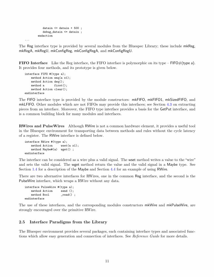
datain <= datain + 500 ;
debug_datain <= datain ;
endaction
...
The Reg interface type is provided by several modules from the Bluespec Library; these include mkReg,mkRegA, mkRegU, mkConfigReg, mkConfigRegA, and mkConfigRegU.
FIFO Interface Like the Reg interface, the FIFO interface is polymorphic on its type – FIFO#(type a).It provides four methods, and its prototype is given below.
interface FIFO #(type a);
method Action enq(a x1);
method Action deq();
method a first();
method Action clear();
endinterface
The FIFO interface type is provided by the module constructors: mkFIFO, mkFIFO1, mkSizedFIFO, andmkLFIFO. Other modules which are not FIFOs may provide this interfaces; see Section 4.3 on extractingpieces from an interface. Moreover, the FIFO type interface provides a basis for the GetPut interface, andis a common building block for many modules and interfaces.
RWires and PulseWires Although RWire is not a common hardware element, it provides a useful toolin the Bluespec environment for transporting data between methods and rules without the cycle latencyof a register. The RWire interface is defined below.
interface RWire #(type a);
method Action wset(a x1);
method Maybe#(a) wget() ;
endinterface
The interface can be considered as a wire plus a valid signal. The wset method writes a value to the “wire”and sets the valid signal. The wget method return the value and the valid signal in a Maybe type. SeeSection 1.4 for a description of the Maybe and Section 4.4 for an example of using RWire.
There are two alternative interfaces for RWires, one in the common Reg interface, and the second is thePulseWire interface, which wraps a RWire without any data.
interface PulseWire #(type a);
method Action send ();
method Bool _read() ;
endinterface
The use of these interfaces, and the corresponding modules constructors mkWire and mkPulseWire, arestrongly encouraged over the primitive RWire.
2.5 Interface Paradigms from the Library
The Bluespec environment provides several packages, each containing interface types and associated func-tions which allow easy generation and connection of interfaces. See Reference Guide for more details.
11
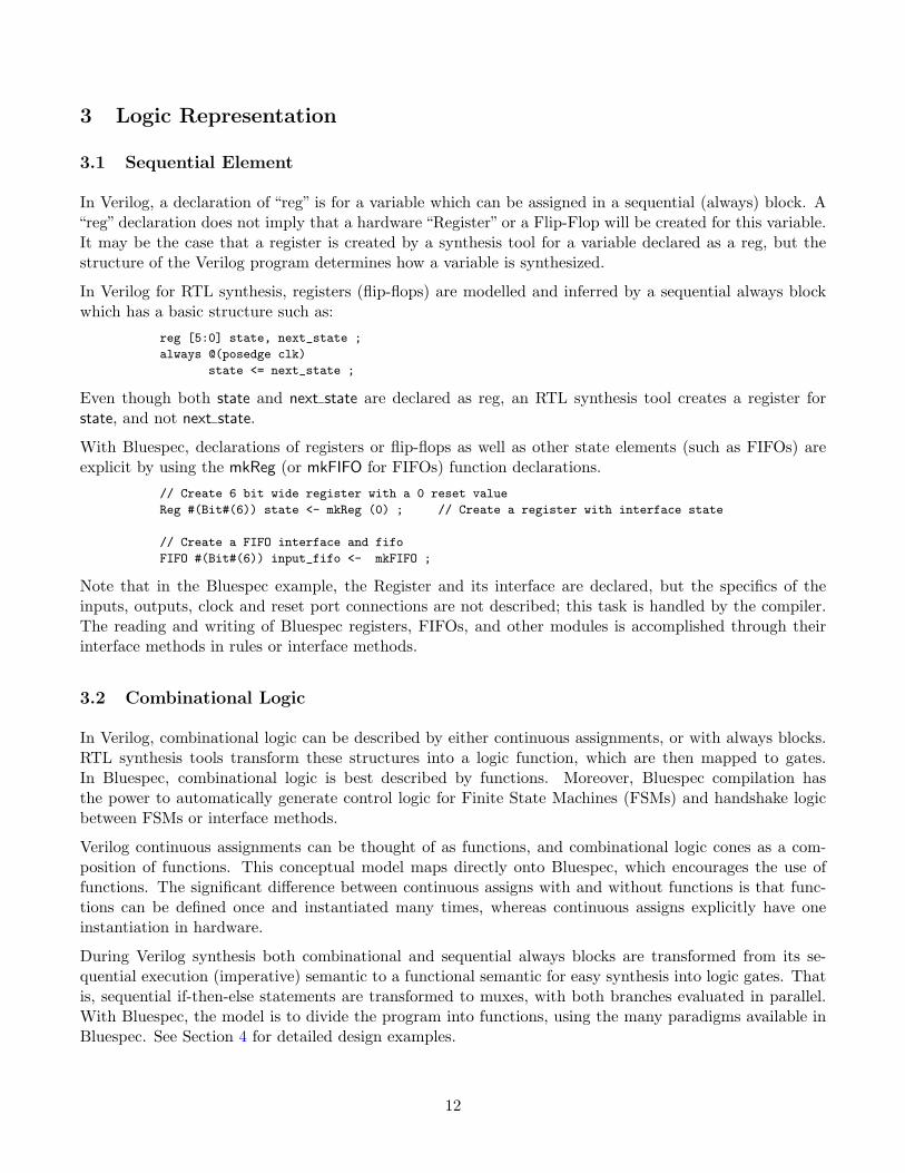
3 Logic Representation
3.1 Sequential Element
In Verilog, a declaration of “reg” is for a variable which can be assigned in a sequential (always) block. A“reg” declaration does not imply that a hardware “Register” or a Flip-Flop will be created for this variable.It may be the case that a register is created by a synthesis tool for a variable declared as a reg, but thestructure of the Verilog program determines how a variable is synthesized.
In Verilog for RTL synthesis, registers (flip-flops) are modelled and inferred by a sequential always blockwhich has a basic structure such as:
reg [5:0] state, next_state ;
always @(posedge clk)
state <= next_state ;
Even though both state and next state are declared as reg, an RTL synthesis tool creates a register forstate, and not next state.
With Bluespec, declarations of registers or flip-flops as well as other state elements (such as FIFOs) areexplicit by using the mkReg (or mkFIFO for FIFOs) function declarations.
// Create 6 bit wide register with a 0 reset value
Reg #(Bit#(6)) state <- mkReg (0) ; // Create a register with interface state
// Create a FIFO interface and fifo
FIFO #(Bit#(6)) input_fifo <- mkFIFO ;
Note that in the Bluespec example, the Register and its interface are declared, but the specifics of theinputs, outputs, clock and reset port connections are not described; this task is handled by the compiler.The reading and writing of Bluespec registers, FIFOs, and other modules is accomplished through theirinterface methods in rules or interface methods.
3.2 Combinational Logic
In Verilog, combinational logic can be described by either continuous assignments, or with always blocks.RTL synthesis tools transform these structures into a logic function, which are then mapped to gates.In Bluespec, combinational logic is best described by functions. Moreover, Bluespec compilation hasthe power to automatically generate control logic for Finite State Machines (FSMs) and handshake logicbetween FSMs or interface methods.
Verilog continuous assignments can be thought of as functions, and combinational logic cones as a com-position of functions. This conceptual model maps directly onto Bluespec, which encourages the use offunctions. The significant difference between continuous assigns with and without functions is that func-tions can be defined once and instantiated many times, whereas continuous assigns explicitly have oneinstantiation in hardware.
During Verilog synthesis both combinational and sequential always blocks are transformed from its se-quential execution (imperative) semantic to a functional semantic for easy synthesis into logic gates. Thatis, sequential if-then-else statements are transformed to muxes, with both branches evaluated in parallel.With Bluespec, the model is to divide the program into functions, using the many paradigms available inBluespec. See Section 4 for detailed design examples.
12

4 System Design Examples
This section describes several design example using Bluespec SystemVerilog.
4.1 Synchronous State Machine
With Bluespec, a state machine can be written by a series of independent rules, which the compiler willproperly order and synthesize control logic. Alternately, the transitions can be combined into a functionand that function instantiated in one rule, which highlights the independent and synchronous nature ofthe rules.
FSM with Multiple Rules
...
typedef enum {S0, S1, S2, S3} StateType
deriving (Eq, Bits);
...
Reg#(StateType) curr_state <- mkReg (S0) ;
(* fire_when_enabled, no_implicit_conditions *)
rule state_S0 (curr_state == S0);
curr_state <= S1;
endrule
(* fire_when_enabled, no_implicit_conditions *)
rule state_S1 (curr_state == S1);
curr_state <= S2;
endrule
(* fire_when_enabled, no_implicit_conditions *)
rule state_S2 (curr_state == S2);
curr_state <= S3;
endrule
(* fire_when_enabled, no_implicit_conditions *)
rule state_S3 (curr_state == S3);
curr_state <= S0;
endrule
...
Each rule corresponds to one or more state transitions, where the rule condition is the current state andinput condition for transition to occur.
Each rule is also annotated with a fire when enabled attribute. This attribute enables compile time checksto insure that other conditions (rules or method will not block the rule execution – basically a check forindependence between rules.) The no implicit conditions attribute, is a compile-time assertion which insuresthat there are no implicit conditions (such as full or empty FIFOs) which would prevent this rule fromfiring. Together, these attribute check the designer’s intentions and understanding of the Bluespec model.
13

FSM with One Rule Alternately, the FSM may be described in one rule, which gives the full FSMbehavior in a case statement.
Reg#(StateType) curr_state <- mkReg (S0) ;
(* fire_when_enabled *)
rule rule1_StateChange (True);
StateType next_state;
case (curr_state)
S0 : next_state = S1;
S1 : next_state = S2;
S2 : next_state = S3;
S3 : next_state = S0;
default : next_state = S0;
endcase
curr_state <= next_state;
endrule: rule1_StateChange
Another One Rule FSM Example This FSM example is a minor variation of the above, where afunction describes the state transitions and the rule instantiates the function. This style has the advantagethat the rule bodies, which update state, and call actions are separate from the function, thus allowingeasier maintenance and reuse.
typedef enum {S0, S1, S2, S3} StateType
deriving (Eq, Bits);
function StateType next_state (StateType curr_state);
let myLocalVar;
case (curr_state)
S0 : myLocalVar = S1;
S1 : myLocalVar = S2;
S2 : myLocalVar = S3;
S3 : myLocalVar = S0;
default : myLocalVar = S0;
endcase
return myLocalVar;
endfunction
...
rule rule1_StateChange (True);
curr_state <= next_state(curr_state);
endrule: rule1_StateChange
Discussion The implementation style for an FSM strongly depends on scope of the FSM within thedesign, where the following guidelines should be used.
• If the FSM implements only the control structure, that is, it provides the next state logic, but doesnot detail the actions which occur within a given state, then the FSM should be implemented in onerule. This is similar to common Verilog styles, and does not take advantage of Bluespec features.
• If the FSM design includes the actions within each state, then the recommended style is one rule pertransition or state arc. That is, given two transition, state A to B and state A to C, there should bea two rules, one per transition.
14
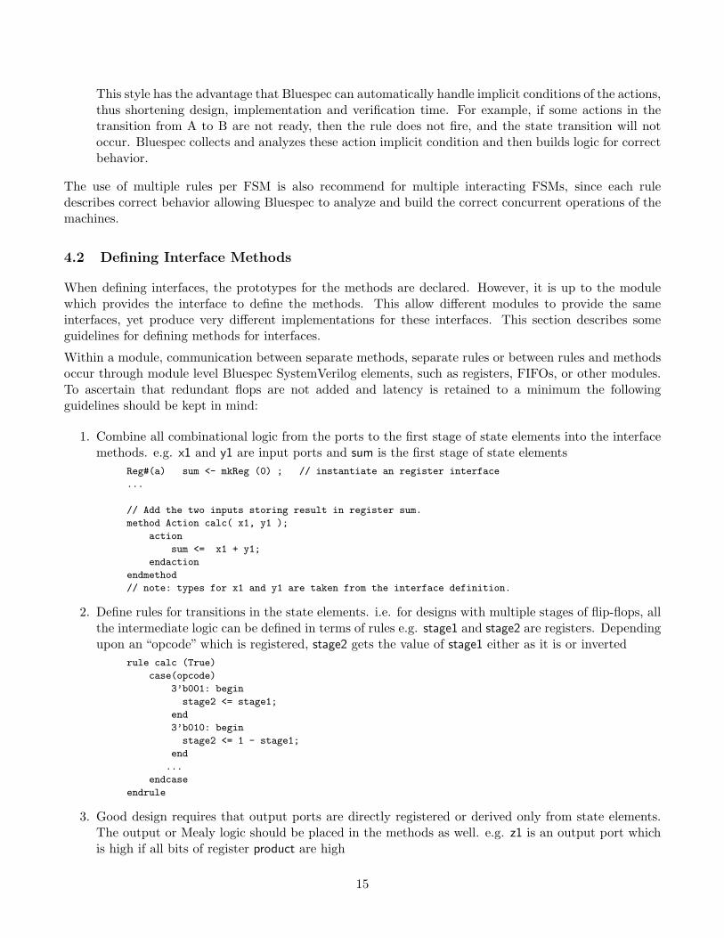
This style has the advantage that Bluespec can automatically handle implicit conditions of the actions,thus shortening design, implementation and verification time. For example, if some actions in thetransition from A to B are not ready, then the rule does not fire, and the state transition will notoccur. Bluespec collects and analyzes these action implicit condition and then builds logic for correctbehavior.
The use of multiple rules per FSM is also recommend for multiple interacting FSMs, since each ruledescribes correct behavior allowing Bluespec to analyze and build the correct concurrent operations of themachines.
4.2 Defining Interface Methods
When defining interfaces, the prototypes for the methods are declared. However, it is up to the modulewhich provides the interface to define the methods. This allow different modules to provide the sameinterfaces, yet produce very different implementations for these interfaces. This section describes someguidelines for defining methods for interfaces.
Within a module, communication between separate methods, separate rules or between rules and methodsoccur through module level Bluespec SystemVerilog elements, such as registers, FIFOs, or other modules.To ascertain that redundant flops are not added and latency is retained to a minimum the followingguidelines should be kept in mind:
1. Combine all combinational logic from the ports to the first stage of state elements into the interfacemethods. e.g. x1 and y1 are input ports and sum is the first stage of state elements
Reg#(a) sum <- mkReg (0) ; // instantiate an register interface
...
// Add the two inputs storing result in register sum.
method Action calc( x1, y1 );
action
sum <= x1 + y1;
endaction
endmethod
// note: types for x1 and y1 are taken from the interface definition.
2. Define rules for transitions in the state elements. i.e. for designs with multiple stages of flip-flops, allthe intermediate logic can be defined in terms of rules e.g. stage1 and stage2 are registers. Dependingupon an “opcode” which is registered, stage2 gets the value of stage1 either as it is or inverted
rule calc (True)
case(opcode)
3’b001: begin
stage2 <= stage1;
end
3’b010: begin
stage2 <= 1 - stage1;
end
...
endcase
endrule
3. Good design requires that output ports are directly registered or derived only from state elements.The output or Mealy logic should be placed in the methods as well. e.g. z1 is an output port whichis high if all bits of register product are high
15
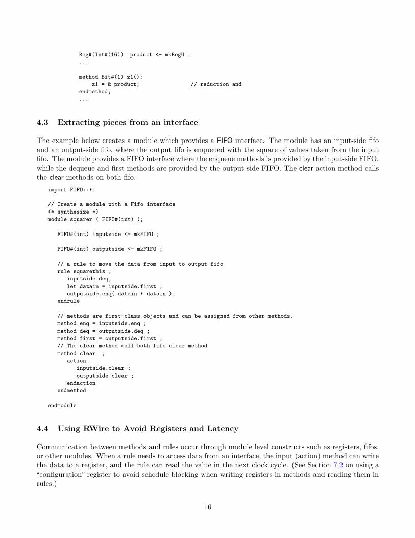
Reg#(Int#(16)) product <- mkRegU ;
...
method Bit#(1) z1();
z1 = & product; // reduction and
endmethod;
...
4.3 Extracting pieces from an interface
The example below creates a module which provides a FIFO interface. The module has an input-side fifoand an output-side fifo, where the output fifo is enqueued with the square of values taken from the inputfifo. The module provides a FIFO interface where the enqueue methods is provided by the input-side FIFO,while the dequeue and first methods are provided by the output-side FIFO. The clear action method callsthe clear methods on both fifo.
import FIFO::*;
// Create a module with a Fifo interface
(* synthesize *)
module squarer ( FIFO#(int) );
FIFO#(int) inputside <- mkFIFO ;
FIFO#(int) outputside <- mkFIFO ;
// a rule to move the data from input to output fifo
rule squarethis ;
inputside.deq;
let datain = inputside.first ;
outputside.enq( datain * datain );
endrule
// methods are first-class objects and can be assigned from other methods.
method enq = inputside.enq ;
method deq = outputside.deq ;
method first = outputside.first ;
// The clear method call both fifo clear method
method clear ;
action
inputside.clear ;
outputside.clear ;
endaction
endmethod
endmodule
4.4 Using RWire to Avoid Registers and Latency
Communication between methods and rules occur through module level constructs such as registers, fifos,or other modules. When a rule needs to access data from an interface, the input (action) method can writethe data to a register, and the rule can read the value in the next clock cycle. (See Section 7.2 on using a“configuration” register to avoid schedule blocking when writing registers in methods and reading them inrules.)
16
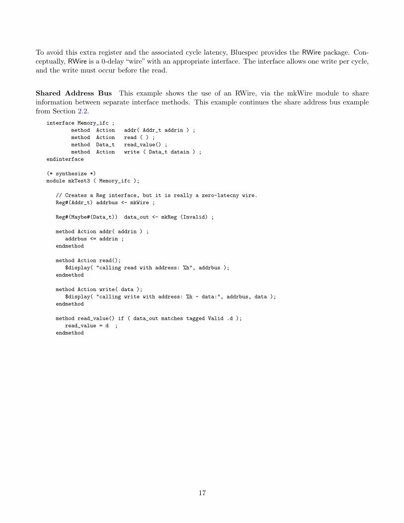
To avoid this extra register and the associated cycle latency, Bluespec provides the RWire package. Con-ceptually, RWire is a 0-delay “wire” with an appropriate interface. The interface allows one write per cycle,and the write must occur before the read.
Shared Address Bus This example shows the use of an RWire, via the mkWire module to shareinformation between separate interface methods. This example continues the share address bus examplefrom Section 2.2.
interface Memory_ifc ;
method Action addr( Addr_t addrin ) ;
method Action read ( ) ;
method Data_t read_value() ;
method Action write ( Data_t datain ) ;
endinterface
(* synthesize *)
module mkTest3 ( Memory_ifc );
// Creates a Reg interface, but it is really a zero-latecny wire.
Reg#(Addr_t) addrbus <- mkWire ;
Reg#(Maybe#(Data_t)) data_out <- mkReg (Invalid) ;
method Action addr( addrin ) ;
addrbus <= addrin ;
endmethod
method Action read();
$display( "calling read with address: %h", addrbus );
endmethod
method Action write( data );
$display( "calling write with address: %h - data:", addrbus, data );
endmethod
method read_value() if ( data_out matches tagged Valid .d );
read_value = d ;
endmethod
17
5 Testbenches
5.1 Controlling Simulation
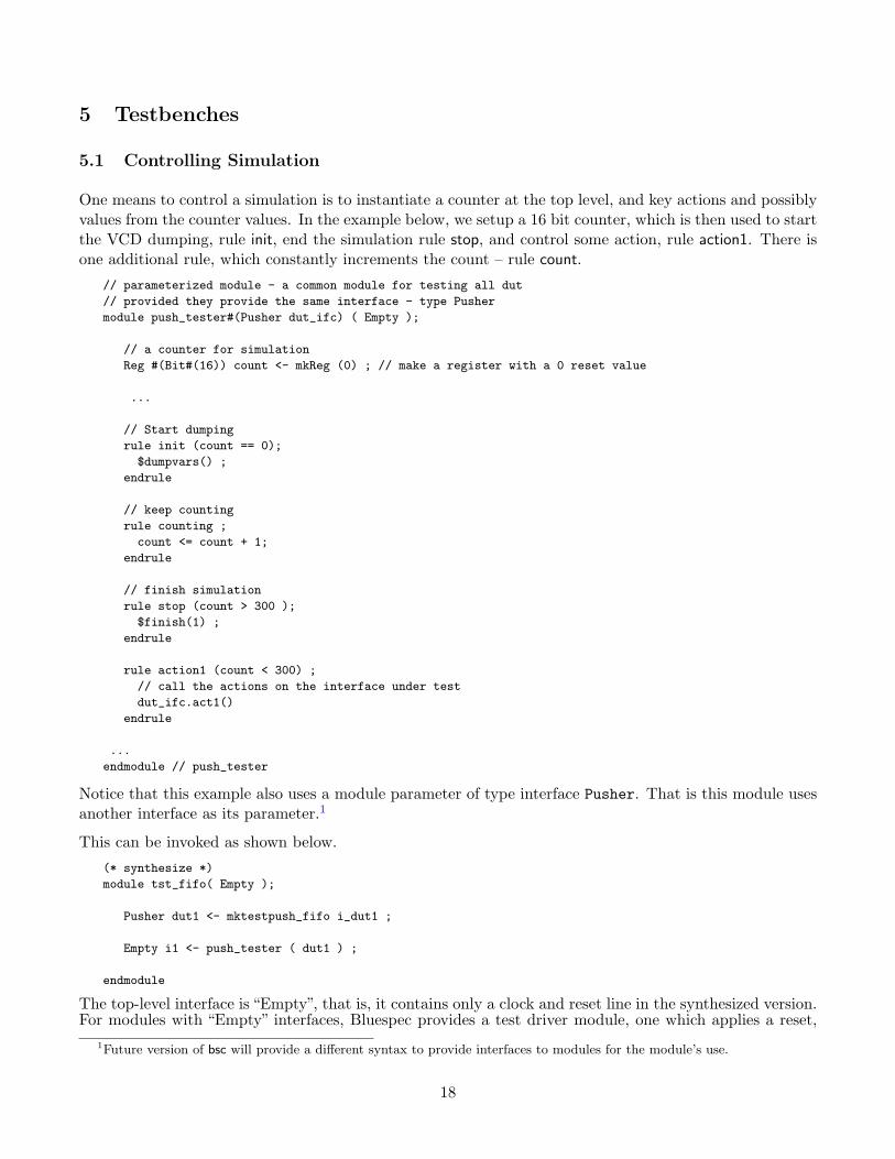
One means to control a simulation is to instantiate a counter at the top level, and key actions and possiblyvalues from the counter values. In the example below, we setup a 16 bit counter, which is then used to startthe VCD dumping, rule init, end the simulation rule stop, and control some action, rule action1. There isone additional rule, which constantly increments the count – rule count.
// parameterized module - a common module for testing all dut
// provided they provide the same interface - type Pusher
module push_tester#(Pusher dut_ifc) ( Empty );
// a counter for simulation
Reg #(Bit#(16)) count <- mkReg (0) ; // make a register with a 0 reset value
...
// Start dumping
rule init (count == 0);
$dumpvars() ;
endrule
// keep counting
rule counting ;
count <= count + 1;
endrule
// finish simulation
rule stop (count > 300 );
$finish(1) ;
endrule
rule action1 (count < 300) ;
// call the actions on the interface under test
dut_ifc.act1()
endrule
...
endmodule // push_tester
Notice that this example also uses a module parameter of type interface Pusher. That is this module usesanother interface as its parameter.1
This can be invoked as shown below.
(* synthesize *)
module tst_fifo( Empty );
Pusher dut1 <- mktestpush_fifo i_dut1 ;
Empty i1 <- push_tester ( dut1 ) ;
endmodule
The top-level interface is “Empty”, that is, it contains only a clock and reset line in the synthesized version.For modules with “Empty” interfaces, Bluespec provides a test driver module, one which applies a reset,
1Future version of bsc will provide a different syntax to provide interfaces to modules for the module’s use.
18
and then drives the clock indefinitely. The module is located in $BLUESPECDIR/Verilog/main.v and canbe invoked by vcs using the following command-line.
vcs $BLUESPECDIR/Verilog/main.v +define+TOP=tst_fifo +libext+.v -y $BLUESPECDIR/Verilog/ *.v
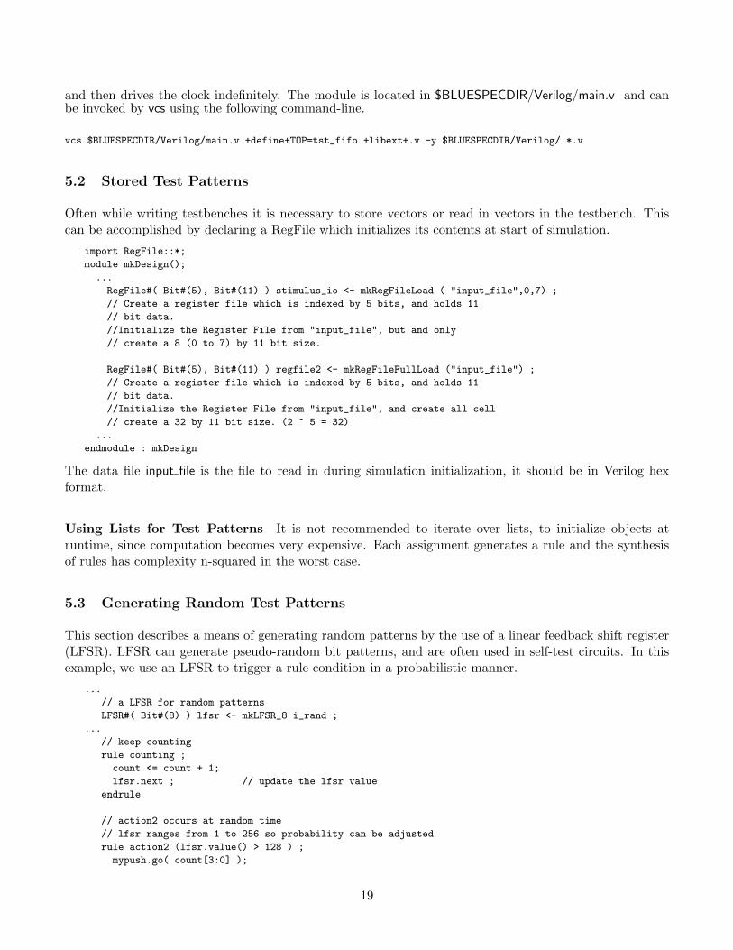
5.2 Stored Test Patterns
Often while writing testbenches it is necessary to store vectors or read in vectors in the testbench. Thiscan be accomplished by declaring a RegFile which initializes its contents at start of simulation.
import RegFile::*;
module mkDesign();
...
RegFile#( Bit#(5), Bit#(11) ) stimulus_io <- mkRegFileLoad ( "input_file",0,7) ;
// Create a register file which is indexed by 5 bits, and holds 11
// bit data.
//Initialize the Register File from "input_file", but and only
// create a 8 (0 to 7) by 11 bit size.
RegFile#( Bit#(5), Bit#(11) ) regfile2 <- mkRegFileFullLoad ("input_file") ;
// Create a register file which is indexed by 5 bits, and holds 11
// bit data.
//Initialize the Register File from "input_file", and create all cell
// create a 32 by 11 bit size. (2 ^ 5 = 32)
...
endmodule : mkDesign
The data file input file is the file to read in during simulation initialization, it should be in Verilog hexformat.
Using Lists for Test Patterns It is not recommended to iterate over lists, to initialize objects atruntime, since computation becomes very expensive. Each assignment generates a rule and the synthesisof rules has complexity n-squared in the worst case.
5.3 Generating Random Test Patterns
This section describes a means of generating random patterns by the use of a linear feedback shift register(LFSR). LFSR can generate pseudo-random bit patterns, and are often used in self-test circuits. In thisexample, we use an LFSR to trigger a rule condition in a probabilistic manner.
...
// a LFSR for random patterns
LFSR#( Bit#(8) ) lfsr <- mkLFSR_8 i_rand ;
...
// keep counting
rule counting ;
count <= count + 1;
lfsr.next ; // update the lfsr value
endrule
// action2 occurs at random time
// lfsr ranges from 1 to 256 so probability can be adjusted
rule action2 (lfsr.value() > 128 ) ;
mypush.go( count[3:0] );
19

$display( "%t - action2 %h", $time, count[3:0] ) ;
endrule
Other LFSR library functions are described in “The Reference Guide”.
20
6 Common Hints and Style Suggestions
This section describes some common issues and restrictions when using Bluespec. Moreover, some oftenoverlooked convenience of Bluespec are also described.
6.1 Identifier Names
A current restriction in Bluespec SystemVerilog requires that type names begin with an uppercase, andthat variable names begin with lower case letters. Type names include typedefs, interfaces, and structures.Variable names include module names, module instance names, interface instantiations, methods names,formal and actual argument names.
If the first character of an instance name is an underscore, (_), the compiler will not generate the name.This is used extensively in the Bluespec libraries as it allows layers of modules inside libraries to be hiddenfrom users of the libraries.
If a user doesn’t want a module instantiation to appear in the hierarchical naming, he can start the instancename with _. This tells the compiler not to generate the name. For example, a module hierarchy of foocalling bar which instantiates readme will generate foo_bar_readme. If instead, the instantiation is named_readme, the final generated name will be foo_bar.
The unintended consequence may be that there are unamed objects generated. For example, if in theBSV code the register names start with an underscore, then they will be converted into unnamed registers.To avoid this, instance names should not start with an underscore, unless the desired behavior is to notgenerate the instance name.
6.2 Use let Variables
let definitions are a short hand step which directs the compiler to resolve and type check variable types.let variable are useful to give meaningful names to intermediate values and also to share intermediatevalues.
let norm1 = normalize( bas_res ) ;
let rounded = round ( norm1 ) ;
as opposed to explicitly declaring the types
FP_I#(8,24) norm1 = normalize( bas_res ) ;
FP_I#(8,25) rounded = round ( norm1 ) ;
One caveat, if too many let declarations are used, BSC may not be able to determine some interme-diate types. This is especially true when there are truncate and extension operations surrounding thesedeclarations.
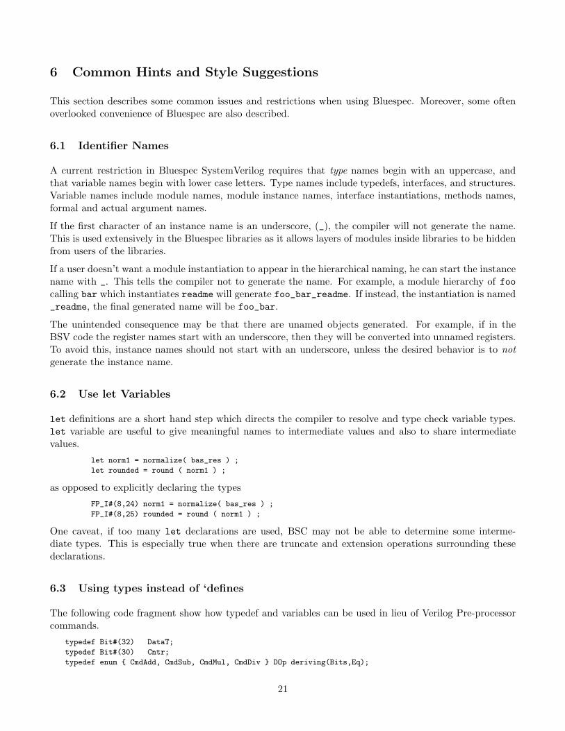
6.3 Using types instead of ‘defines
The following code fragment show how typedef and variables can be used in lieu of Verilog Pre-processorcommands.
typedef Bit#(32) DataT;
typedef Bit#(30) Cntr;
typedef enum { CmdAdd, CmdSub, CmdMul, CmdDiv } DOp deriving(Bits,Eq);
21

typedef struct {
Cntr counter ;
DataT data1;
DataT data2;
DOp opcode} Cmd
deriving(Bits) ;
typedef Tuple5#(Cntr,DataT,DataT,DOp,Cntr) CmdCnt;
Integer numAdd = 5;
Integer numMul = 3;
Integer numDiv = 1;
Integer numTotal = numAdd + numMul + numDiv;
These definitions can be specified in a file and accessed via the import syntax.
6.4 Adding Monitors
To aid in design debug, there are several bsc techniques which can be used, either alone or in combination.
BSC options Use the -keep-fires option on the bsc command line. Verilog code generated with this optionwill keep all the CAN FIRE <rule> and the WILL FIRE <rule> signals, even if they can be optimizedaway.
Synthesis Directives By adding (* synthesize *) directive on modules, the Bluespec generated Verilogwill have more levels of hierarchy, which may allow easier debug. Note that the scheduling phaseof Bluespec may produce a different, typically less optimized, scheduler than one where the entiredesign is scheduled. Hence these synthesis directives should be removed before gate-level synthesis.Note that the synthesis directive can only be used on non-polymorphic modules.
Functions can also be synthesized as a Verilog module, by preceding the function with a (* noinline*) attribute. Like the (* synthesize *) directive the generated Verilog may be less efficient whenusing this attribute, since optimizations cannot take place across these boundaries. Parameterizedfunctions cannot be synthesized directly into Verilog.
Adding Hardware Monitors Yet another technique is to add a “monitor signal” or Probe. Probes arenot optimized nor removed in Bluespec, so the signal will remain for debug. For example,
...
Probe#(Data_t) debug_datain1 <- mkProbe ;
...
rule someRule ( ... ) ;
...
debug_datain1 <= ...
...
endrule
...
Note that these types of monitors can only be added in a module context, that is not in functions,and can only be assigned in action contexts, such as rules, or action methods.
22

7 Helping the Scheduler
7.1 Rules versus Always Blocks
Consider the following Verilog code fragment, and a corresponding (incorrect) Bluespec model.reg [31:0] burst_count, dest_burst_size ;
reg burst_in_progress ;
...
always @(posedge clk) // burst_in_progress_stop
begin
if (burst_in_progress && (burst_count==dest_burst_size))
burst_in_progress <= False;
...
end
always @(posedge clk) // burst_count;
begin
burst_count <= burst_in_progress ? burst_count+1 : 0;
...
end
Incorrect Bluespec model:...
Reg#(Data_t) dest_burst_size <- mkReg (32’h0) ;
Reg#(Data_t) burst_count <- mkReg (0) ;
Reg#(Bool) burst_in_progress <- mkReg (False) ;
rule burst_in_progress_stop (burst_in_progress && (burst_count==dest_burst_size));
burst_in_progress <= False;
...
endrule
rule burst_counting ;
burst_count <= burst_in_progress ? burst_count + 1 : 0;
...
endrule
At first inspection the Bluespec code may look equivalent, but the scheduler sees the cross correlationbetween the rules. That is, Rule burst counting reads burst in progress and updates register burst countRule burst in progress reads burst count and sets burst in progress.
For the scheduler to allow the rules to happen in parallel, they must be able to occur in any order and stillgive the same result. If Rule burst counting happens first, then register burst count can be updated suchthat rule burst counting become disabled; a similar argument happens in the other directions.
A corrected model is below, which combines the two rules into one rule which only occurs when burst in progressis True. Note that the two actions in the rule can be listed in either order, since all actions in one ruleoccur concurrently.
...
Reg#(Data_t) dest_burst_size <- mkReg (32’h0) ;
Reg#(Data_t) burst_count <- mkReg (0) ;
Reg#(Bool) burst_in_progress <- mkReg (False) ;
rule burst_in_progress_stop (burst_in_progress) ;
burst_in_progress <= burst_count != dest_burst_size ;
burst_count <= (burst_count != dest_burst_size) ? burst_count+1 : 0;
23

...
endrule
7.2 Alleviating Read/Write Conflicts with ConfigReg
According to term-rewriting semantics, rules are thought of as firing one-at-a-time sequentially. Fromthis point of view, the scheduling logic’s job is not only to generate this sequence, but also to divide itinto ”chunks”, so all the rules in a chunk fire during the same clock. However, if the rules involve severalregisters, all the reads from these registers will be performed near the beginning of the clock cycle, andall the writes at the end. It follows that any rule (or method) which reads a register must occur earlier inthe TRS sequence as one which writes to it. Sometimes, however, there are conflicting constraints betweentwo rules; if so, those two rules cannot be scheduled in the same chunk (that is, fired on the same clock).
An example of this occurs when a method writes to a register which is read by an internal rule. Fortechnical reasons a module’s methods are always scheduled first in a chunk, earlier than all the internalrules, and with greater urgency. So this combination of circumstances would mean that the method andthe rule can never fire together, and the rule will be inhibited whenever the method fires.
This situation often occurs with configuration registers, which are written by an external method (connectedto some local bus mechanism) which writes the register on every clock (though the value written changesvery rarely). In this case a rule reading the register would be starved out completely, and never fire.
The ConfigReg package was designed to address this issue. A ConfigReg has the same interface as a Reg,and the Verilog implementation for mkReg and mkConfigReg are also identical. The only difference is thescheduling information specified in the ”import “BVI” wrapper – for ordinary registers, reads must occurbefore writes (as described above); for ConfigReg’s, the two methods are conflict-free, so reads may occurbefore or afterwards.
Thus the conflict described above no longer occurs. The downside is that the value read, whether the readoccurs before or after a write within the same chunk, will always be the contents of the register at thebeginning of the chunk – that is, the value might be slightly stale. In the case of configuration registersthis does not normally matter – the parameters are set very rarely, and a one-clock difference is neitherhere nor there.
7.3 Register Updates
In Bluespec registers are considered atomic units with regard to their updates. That is, if any bit of aregister is updated, then the entire register is considered updated. As an example, consider the follow codefragment. There are two rules which each update a separate byte of a 32 bit register. Bluespec semanticssay that these two rules conflict, since both are updating the same register.
Reg#(Bit#(32)) reg1 <- mkReg(0) ;
rule updateByte1 ( r1 ) ;
reg1[7:0] <= 8’d4 ;
endrule
rule updateByte3 ( r2 ) ;
reg1[23:16] <= 8’d5 ;
endrule
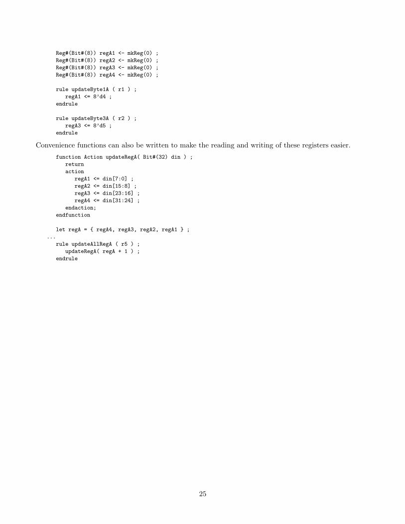
A better methodology is to define four 8-bit registers, and update the bytes a needed, if this is the intendedbehavior. This style of coding has been observed to have better synthesis results.
24
Reg#(Bit#(8)) regA1 <- mkReg(0) ;
Reg#(Bit#(8)) regA2 <- mkReg(0) ;
Reg#(Bit#(8)) regA3 <- mkReg(0) ;
Reg#(Bit#(8)) regA4 <- mkReg(0) ;
rule updateByte1A ( r1 ) ;
regA1 <= 8’d4 ;
endrule
rule updateByte3A ( r2 ) ;
regA3 <= 8’d5 ;
endrule
Convenience functions can also be written to make the reading and writing of these registers easier.
function Action updateRegA( Bit#(32) din ) ;
return
action
regA1 <= din[7:0] ;
regA2 <= din[15:8] ;
regA3 <= din[23:16] ;
regA4 <= din[31:24] ;
endaction;
endfunction
let regA = { regA4, regA3, regA2, regA1 } ;
...
rule updateAllRegA ( r5 ) ;
updateRegA( regA + 1 ) ;
endrule
25

8 Debugging Hints and Tips
8.1 Viewing Complex Data Structures
Advanced data structures, such as vectors, lists, and structures, are difficult to view during simulation anddebugging since they are converted into bits during compilation. You can use the Probe primitive which isprovided in the Bluespec library, to ensure that signals of interest are not optimized away by the compilerand are given a known name. The Probe primitive is used just like a register, except that only a writemethod exists. Since reads are not available, a Probe does not impact scheduling. associated signal willbe named just like the port of any Verilog module, in this case <instance_name>$PROBE, but no actualProbe instance will be created.
The first step is to define a specialized probe module based on the module mkProbe provided in the BSVlibrary. In this example we’ll call our module mkS_Probe. This module instantiates a mkProbe module foreach field of the structure and defines the write method to include each field of the structure.
The specialized module, mkS_Probe, has to be kept in sync with the structure definition. For each fieldadded to the structure, two lines must be added to the mkS_Probe module definition; one for the instan-tiation and one for the write. A unique module must be written for each unique data structure, but theyall use the same basic techniques.
// Probe library is needed for this technique
import Probe :: * ;
// Define a struct, for which we want to see the internals
typedef struct {
Bit#(sx) xx;
Bit#(st) tt;
Bool zz ;
} MyS #( type sx, type st )
deriving ( Bits, Eq );
// Here we define a module specific to the MyS structure above.
// This module provides the Probe interface, and hence works exactly like the
// mkProbe module.
// This module should be keep in sync with the structure definition
// above. 2 lines are need for each new field added - one to
// instantiate the mkProbe module and one for the write.
module mkS_Probe( Probe#(MyS#(x,y)) ) ;
// We need to instantiate a mkProbe module for each field of the
// structure which we wish to probe. By using the let "type", we
// leave the type determination to the bsc compiler
let xx <- mkProbe ;
let tt <- mkProbe ; // new fields added in structure above
let zz <- mkProbe ; // must be added here
// The Probe interface has one method, which we must provide in
// this module. A _write action causes all the sub-probes to be
// written as well.
method Action _write( s ) ;
xx <= s.xx ;
tt <= s.tt ; // new fields added in structure above
zz <= s.zz ; // must be added here
endmethod
26

endmodule
Once we’ve defined the mkS_Probe module, we can use it to view the signals in the structure. The remainderof this code shows an example of using mkProbe and mkS_Probe.
// Define an interface and module for the example.
interface Foo ;
method Bit#(4) mx;
method Bit#(7) mt ;
method MyS#(4,7) ms ;
endinterface
(* synthesize *)
module mkTest( Foo ) ;
let init_s = MyS{ xx: 0, tt:1, zz: True } ;
// Create a register to hold the structure listed above.
Reg#(MyS#(4,7)) r <- mkReg( init_s ) ;
// Define a regular probe and the specialized probe modules
let rprobe <- mkProbe ;
let rprobe_current <- mkS_Probe ;
let rprobe_new <- mkS_Probe ;
// Probe can only be written in an action context, - e.g. a rule
// or an action method.
rule r1 ( True );
rprobe <= r ; // Write the regular probe
rprobe_current <= r ; // Write the specialized probe with
// the current value
let ns = MyS{xx: r.xx + 5,
tt: r.tt + 3,
zz: r.zz } ;
rprobe_new <= ns ; // Write the specialized probe
// with the "new" value
r <= ns ;
endrule
method mx = r.xx ;
method mt = r.tt ;
method ms = r ;
endmodule
After compiling, the generated Verilog will contain signals named <instance_name>$PROBE, however noactual Probe instance will be created. The only side effects of a BSV Probe instantiation relate to thenaming and retention of the associated signal in the generated Verilog.
In the generated Verilog code, the following code segment will be found.
// probes
assign rprobe$PROBE = r ;
assign rprobe_current_xx$PROBE = r[11:8] ;
assign rprobe_current_tt$PROBE = r[7:1] ;
assign rprobe_current_zz$PROBE = r[0] ;
assign rprobe_new_xx$PROBE = x__h365 ;
assign rprobe_new_tt$PROBE = x__h385 ;
27

assign rprobe_new_zz$PROBE = r[0] ;
The first line corresponds to the rprobe, and the is assigned the current value of r[11:0]. The structureinformation is not present. The next 3 lines show the rprobe_current instance of mkS_Probe module,while the last 3 lines show the rprobe_new instance. Note that within each of these instances the specificstructure fields are presented, which will aid in the observation of the design. For net-list synthesis, thesesignals will be removed, since they are not connected to further down-stream logic.
28
9 BlueSim
This section focuses on BlueSim, the native Bluespec simulator.
9.1 Improving Simulation Speed
The user has a great deal of control over how well the simulation execution performs. A poorly writtenmodel or testbench can slow down the simulation by orders of magnitude.
Initialization
Use the RegFile primitive to create and initialize data arrays with very low overhead.
Avoid any initialization which requires runtime actions or rules. These rules must be checked at everyclock in the simulation.
Avoid creating data at initialization time for the same reason.
Rule Writing
Any source code which causes many (hundreds or thousands) of rules to be created will execute slowly.
Avoid using rules whose predicate is True. These will be scheduled on every tick. If possible, have all rulesdepend on computed conditions.
One large factor in simulation overhead is scheduling the rule firings. Using simple predicates and ajudicious economy of rules will greatly speed simulation.
Computations
Long case statements generate complex code. If possible, use a RegFile or a computation to derive a code,then use the code to control the simulation behavior.
The compiler is very good at finding common subexpressions and other normal optimizations, so the userneed not worry about these.
29

10 Other Notes
10.1 Using Bluespec with other tools
When using a simulator and other Design automation tools, Verilog modules from the Bluespec librarywill need to be included during elaboration. The examples below show how this can be accomplished viacommand line or command script
Simulators and other tool Simulators typically require that the Verilog library directory is specified.Bluespec provides Verilog definitions for these“primitive”modules in $BLUESPECDIR/Verilog/, whichbe accessed in most simulators as:
vcs,ncverilog +libext+.v -y $BLUESPECDIR/Verilog/ *.v
Design Compiler can access Bluespec’s Verilog library by adding the following to command scripts orin the /.synopsys dc.setup file.
bluespecdir = get_unix_variable("BLUESPECDIR")
search_path = search_path + {bluespecdir + "/Verilog"}
Be sure to ungroup the library elements, especially registers, since DC can simplify the registerinstantiate if constant inputs are known compile -ungroup all
May want to set DC variable’s compile sequential area recovery to true, since this instructs dc toreconsider its choice of sequential cells.
30
11 Using Existing Verilog Components in a BSV Design
The importBVI statement is used to include existing Verilog components in a BSV module allowing thedesigner to reuse existing components and design components for reuse. The wrapper, or code around theVerilog program, can be polymorphic to allow reuse in a variety of designs. Since a polymorphic modulecannot be synthesized, for synthesis, a non-polymorphic instance of the module is instantiated in whichvalues for the parameters are specified.
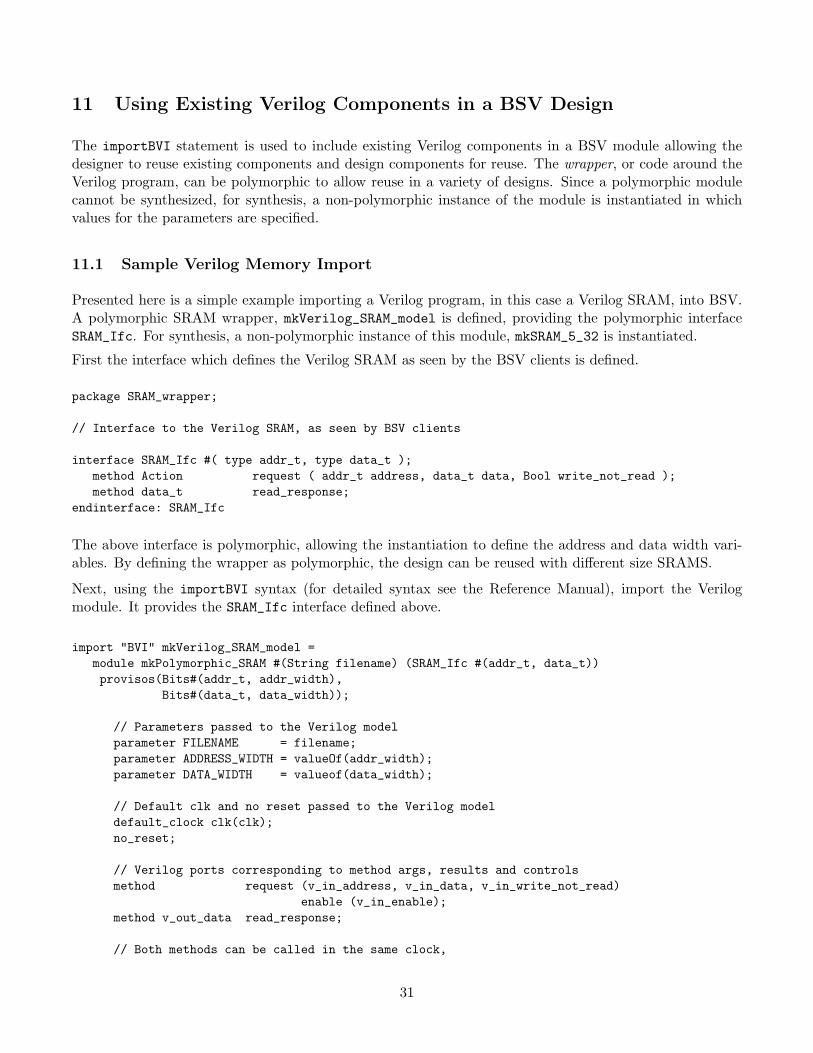
11.1 Sample Verilog Memory Import
Presented here is a simple example importing a Verilog program, in this case a Verilog SRAM, into BSV.A polymorphic SRAM wrapper, mkVerilog_SRAM_model is defined, providing the polymorphic interfaceSRAM_Ifc. For synthesis, a non-polymorphic instance of this module, mkSRAM_5_32 is instantiated.
First the interface which defines the Verilog SRAM as seen by the BSV clients is defined.
package SRAM_wrapper;
// Interface to the Verilog SRAM, as seen by BSV clients
interface SRAM_Ifc #( type addr_t, type data_t );method Action request ( addr_t address, data_t data, Bool write_not_read );method data_t read_response;
endinterface: SRAM_Ifc
The above interface is polymorphic, allowing the instantiation to define the address and data width vari-ables. By defining the wrapper as polymorphic, the design can be reused with different size SRAMS.
Next, using the importBVI syntax (for detailed syntax see the Reference Manual), import the Verilogmodule. It provides the SRAM_Ifc interface defined above.
import "BVI" mkVerilog_SRAM_model =module mkPolymorphic_SRAM #(String filename) (SRAM_Ifc #(addr_t, data_t))provisos(Bits#(addr_t, addr_width),
Bits#(data_t, data_width));
// Parameters passed to the Verilog modelparameter FILENAME = filename;parameter ADDRESS_WIDTH = valueOf(addr_width);parameter DATA_WIDTH = valueof(data_width);
// Default clk and no reset passed to the Verilog modeldefault_clock clk(clk);no_reset;
// Verilog ports corresponding to method args, results and controlsmethod request (v_in_address, v_in_data, v_in_write_not_read)
enable (v_in_enable);method v_out_data read_response;
// Both methods can be called in the same clock,
31
// but read_response must logically precede requestschedule (read_response) SB (request);
endmodule
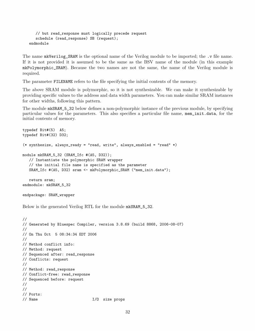
The name mkVerilog_SRAM is the optional name of the Verilog module to be imported; the .v file name.If it is not provided it is assumed to be the same as the BSV name of the module (in this examplemkPolymorphic_SRAM). Because the two names are not the same, the name of the Verilog module isrequired.
The parameter FILENAME refers to the file specifying the initial contents of the memory.
The above SRAM module is polymorphic, so it is not synthesizable. We can make it synthesizable byproviding specific values to the address and data width parameters. You can make similar SRAM instancesfor other widths, following this pattern.
The module mkSRAM_5_32 below defines a non-polymorphic instance of the previous module, by specifyingparticular values for the parameters. This also specifies a particular file name, mem_init.data, for theinitial contents of memory.
typedef Bit#(5) A5;typedef Bit#(32) D32;
(* synthesize, always_ready = "read, write", always_enabled = "read" *)
module mkSRAM_5_32 (SRAM_Ifc #(A5, D32));// Instantiate the polymorphic SRAM wrapper// the initial file name is specified as the parameterSRAM_Ifc #(A5, D32) sram <- mkPolymorphic_SRAM ("mem_init.data");
return sram;endmodule: mkSRAM_5_32
endpackage: SRAM_wrapper
Below is the generated Verilog RTL for the module mkSRAM_5_32.
//// Generated by Bluespec Compiler, version 3.8.69 (build 8868, 2006-08-07)//// On Thu Oct 5 08:34:34 EDT 2006//// Method conflict info:// Method: request// Sequenced after: read_response// Conflicts: request//// Method: read_response// Conflict-free: read_response// Sequenced before: request////// Ports:// Name I/O size props
32
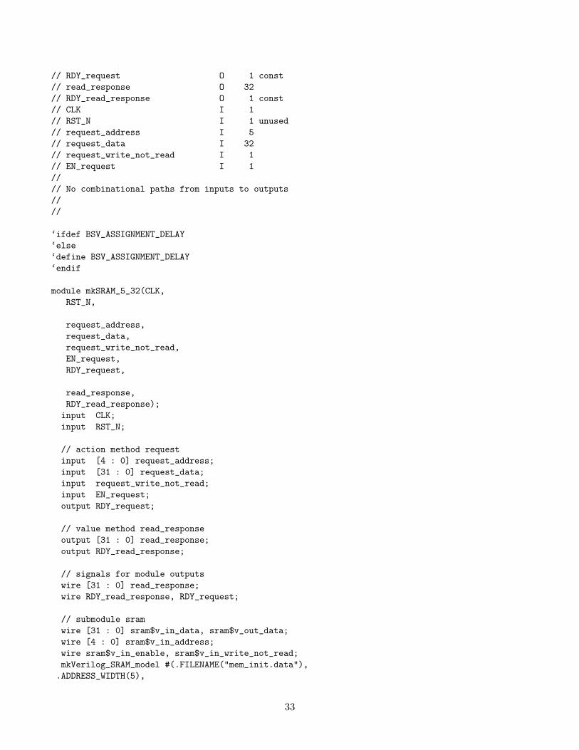
// RDY_request O 1 const// read_response O 32// RDY_read_response O 1 const// CLK I 1// RST_N I 1 unused// request_address I 5// request_data I 32// request_write_not_read I 1// EN_request I 1//// No combinational paths from inputs to outputs////
‘ifdef BSV_ASSIGNMENT_DELAY‘else‘define BSV_ASSIGNMENT_DELAY‘endif
module mkSRAM_5_32(CLK,RST_N,
request_address,request_data,request_write_not_read,EN_request,RDY_request,
read_response,RDY_read_response);input CLK;input RST_N;
// action method requestinput [4 : 0] request_address;input [31 : 0] request_data;input request_write_not_read;input EN_request;output RDY_request;
// value method read_responseoutput [31 : 0] read_response;output RDY_read_response;
// signals for module outputswire [31 : 0] read_response;wire RDY_read_response, RDY_request;
// submodule sramwire [31 : 0] sram$v_in_data, sram$v_out_data;wire [4 : 0] sram$v_in_address;wire sram$v_in_enable, sram$v_in_write_not_read;mkVerilog_SRAM_model #(.FILENAME("mem_init.data"),.ADDRESS_WIDTH(5),
33

.DATA_WIDTH(32)) sram(.clk(CLK),.v_in_address(sram$v_in_address),.v_in_data(sram$v_in_data),.v_in_write_not_read(sram$v_in_write_not_read),.v_in_enable(sram$v_in_enable),.v_out_data(sram$v_out_data));
// action method requestassign RDY_request = 1’d1 ;
// value method read_responseassign read_response = sram$v_out_data ;assign RDY_read_response = 1’d1 ;
// submodule sramassign sram$v_in_address = request_address ;assign sram$v_in_data = request_data ;assign sram$v_in_enable = EN_request ;assign sram$v_in_write_not_read = request_write_not_read ;
endmodule // mkSRAM_5_32
34