programmable controllers (analog control edition) · fx3g/fx3u/fx3uc plc user's manual -...
TRANSCRIPT

Programmable Controllers
U(Analo
FX3
MITSUBIS
MITSUBISHI ELECTRIC
01082010JY997D16701Version H
g Control Edition)
ser's ManualG/FX3U/F
HI ELECTRIC INDUS
X3UC
TRIAL AUTOMATION


Safety Precautions(Read these precautions before use.)
Before installation, operation, maintenance or inspection of this product, thoroughly read through andunderstand this manual and all of the associated manuals. Also, take care to handle the module properly andsafely.
This manual classifies the safety precautions into two categories: and .
Depending on the circumstances, procedures indicated by may also cause severe injury.It is important to follow all precautions for personal safety.Store this manual in a safe place so that it can be taken out and read whenever necessary. Always forward itto the end user.
1. DESIGN PRECAUTIONS
Indicates that incorrect handling may cause hazardous conditions, resulting indeath or severe injury.
Indicates that incorrect handling may cause hazardous conditions, resulting inmedium or slight personal injury or physical damage.
• Make sure to have the following safety circuits outside of the PLC to ensure safe system operation even duringexternal power supply problems or PLC failure.Otherwise, malfunctions may cause serious accidents.1) Most importantly, have the following: an emergency stop circuit, a protection circuit, an interlock circuit for
opposite movements (such as normal vs. reverse rotation), and an interlock circuit (to prevent damage to theequipment at the upper and lower positioning limits).
2) Note that when the PLC CPU detects an error, such as a watchdog timer error, during self-diagnosis, alloutputs are turned off. Also, when an error that cannot be detected by the PLC CPU occurs in an input/outputcontrol block, output control may be disabled.External circuits and mechanisms should be designed to ensure safe machinery operation in such a case.
3) Note that the output current of the service power supply for sensors varies depending on the model and theabsence/presence of extension blocks. If an overload occurs, the voltage automatically drops, inputs in thePLC are disabled, and all outputs are turned off.External circuits and mechanisms should be designed to ensure safe machinery operation in such a case.
4) Note that when an error occurs in a relay, triac or transistor output device, the output could be held either on oroff.For output signals that may lead to serious accidents, external circuits and mechanisms should be designed toensure safe machinery operation in such a case.
• Do not bundle the control line together with or lay it close to the main circuit or power line. As a guideline, lay the control line at least 100mm(3.94") or more away from the main circuit or power line.Noise may cause malfunctions.
• Make sure to ground the shield wire or shield of the shielded cable connected to an analog input expansion board,special adapter, or special function block at one point on the PLC.However, do not use common grounding with heavy electrical systems.Noise may cause malfunctions.
• Make sure to ground the shield wire or shield of the shielded cable connected to an analog output expansionboard, special adapter, or special function block at one point on the analog device side.However, do not use common grounding with heavy electrical systems.Noise may cause malfunctions.
• Install module so that excessive force will not be applied to the power connectors or terminal blocks.Failure to do so may result in wire damage/breakage or PLC failure.
(1)

Safety Precautions(Read these precautions before use.)
2. WIRING PRECAUTIONS
• Make sure to cut off all phases of the power supply externally before attempting wiring work.Failure to do so may cause electric shock or damages to the product.
• Connect the DC power supply wiring to the dedicated terminals described in this manual.If an AC power supply is connected to a DC input/output terminal or DC power supply terminal, the PLC will beburnt out.
• Do not wire vacant terminals externally.Doing so may damage the product.
• Perform class D grounding (grounding resistance: 100Ω or less) to the grounding terminal on the main unit.Do not use common grounding with heavy electrical systems.
• When drilling screw holes or wiring, make sure cutting or wire debris does not enter the ventilation slits.Failure to do so may cause fire, equipment failures or malfunctions.
• Make sure to observe the following precautions in order to prevent malfunctions under the influence of noise:- Do not bundle the power line or twisted shielded cable together with or lay it close to the main circuit, high-
voltage line, or load line.Otherwise, noise disturbance and/or surge induction are likely to take place. As a guideline, lay the control line at least 100mm (3.94") or more away from the main circuit, high-voltage line, or load line.
- Ground the shield of the analog input/output cable at one point on the signal receiving side. However, do not use common grounding with heavy electrical systems.
• Make sure to properly wire to the European terminal board in accordance with the following precautions.Failure to do so may cause electric shock, equipment failures, a short-circuit, wire breakage, malfunctions, ordamage to the product.- The disposal size of the cable end should follow the dimensions described in the manual.- Tightening torque should follow the specifications in the manual.- Twist the end of strand wire and make sure there are no loose wires. - Do not solder-plate the electric wire ends.- Do not connect more than the specified number of wires or electric wires of unspecified size.- Affix the electric wires so that neither the terminal block nor the connected parts are directly stressed.
• Make sure to properly wire the terminal block in accordance with the following precautions.Failure to do so may cause electric shock, equipment failures, a short-circuit, wire breakage, malfunctions, ordamage to the product.- The disposal size of the cable end should follow the dimensions described in the manual.- Tightening torque should follow the specifications in the manual.
(2)

Safety Precautions(Read these precautions before use.)
3. STARTUP AND MAINTENANCE PRECAUTIONS
• Do not touch any terminal while the PLC's power is on.Doing so may cause electrical shock or malfunctions.
• Before cleaning or retightening terminals, cut off all phases of the power supply externally.Failure to do so may cause electric shock.
• Before modifying or disrupting the program in operation or running the PLC, carefully read through this manualand the associated manuals and ensure the safety of the operation.An operation error may damage the machinery or cause accidents.
• Do not change the program in the PLC from two or more peripheral equipment devices at the same time. (i.e. froma programming tool and a GOT)Doing so may cause destruction or malfunction of the PLC program.
• Do not disassemble or modify the PLC.Doing so may cause fire, equipment failures, or malfunctions.For repair, contact your local Mitsubishi Electric distributor.
• Turn off the power to the PLC before connecting or disconnecting any extension cable.Failure to do so may cause equipment failures or malfunctions.
• Turn of the power to the PLC before attaching or detaching the peripheral devices, expansion boards, specialadapters, and extension blocks.Failure to do so may cause equipment failures or malfunctions.
(3)

Safety Precautions(Read these precautions before use.)
MEMO
(4)

FX3G/FX3U/FX3UC PLC User's Manual - Analog Control Edition
FX3G/FX3U/FX3UC Series Programmable Controllers
User's Manual [Analog Control Edition]
ForewordThis manual describes the "analog" function of the MELSEC-F FX Series programmable controllers and should be read and understood before attempting to install or use the unit.Store this manual in a safe place so that you can take it out and read it whenever necessary. Always forward it to the end user.
© 2005 MITSUBISHI ELECTRIC CORPORATION
Manual number JY997D16701
Manual revision H
Date 8/2010
This manual confers no industrial property rights or any rights of any other kind, nor does it confer any patentlicenses. Mitsubishi Electric Corporation cannot be held responsible for any problems involving industrial propertyrights which may occur as a result of using the contents noted in this manual.
1

FX3G/FX3U/FX3UC PLC User's Manual - Analog Control Edition
Outline Precautions• This manual provides information for the use of the FX3U Series Programmable Controllers. The manual
has been written to be used by trained and competent personnel. The definition of such a person or persons is as follows;
1) Any engineer who is responsible for the planning, design and construction of automatic equipmentusing the product associated with this manual should be of a competent nature, trained and qualifiedto the local and national standards required to fulfill that role. These engineers should be fully aware ofall aspects of safety with regards to automated equipment.
2) Any commissioning or service engineer must be of a competent nature, trained and qualified to thelocal and national standards required to fulfill that job. These engineers should also be trained in theuse and maintenance of the completed product. This includes being completely familiar with allassociated documentation for the said product. All maintenance should be carried out in accordancewith established safety practices.
3) All operators of the completed equipment should be trained to use that product in a safe andcoordinated manner in compliance to established safety practices. The operators should also befamiliar with documentation which is connected with the actual operation of the completed equipment.
Note: The term 'completed equipment' refers to a third party constructed device which contains or uses the product associated with this manual
• This product has been manufactured as a general-purpose part for general industries, and has not been designed or manufactured to be incorporated in a device or system used in purposes related to human life.
• Before using the product for special purposes such as nuclear power, electric power, aerospace, medicine or passenger movement vehicles, consult with Mitsubishi Electric.
• This product has been manufactured under strict quality control. However when installing the product where major accidents or losses could occur if the product fails, install appropriate backup or failsafe functions in the system.
• When combining this product with other products, please confirm the standard and the code, or regulations with which the user should follow. Moreover, please confirm the compatibility of this product to the system, machine, and apparatus with which a user is using.
• If in doubt at any stage during the installation of the product, always consult a professional electrical engineer who is qualified and trained to the local and national standards. If in doubt about the operation or use, please consult the nearest Mitsubishi Electric distributor.
• Since the examples indicated by this manual, technical bulletin, catalog, etc. are used as a reference, please use it after confirming the function and safety of the equipment and system. Mitsubishi Electric will accept no responsibility for actual use of the product based on these illustrative examples.
• This manual content, specification etc. may be changed without a notice for improvement.• The information in this manual has been carefully checked and is believed to be accurate; however, if you
have noticed a doubtful point, a doubtful error, etc., please contact the nearest Mitsubishi Electric distributor.
Registration• The company name and the product name to be described in this manual are the registered trademarks or
trademarks of each company.
2

FX3G/FX3U/FX3UC PLC User's Manual - Analog Control Edition Table of Contents
Table of ContentsSAFETY PRECAUTIONS .................................................................................................. (1)
Common Items
1. Introduction A-1
1.1 Outline and Features of Analog Control.......................................................................................A-11.1.1 Analog input control......................................................................................................................A-21.1.2 Analog output control....................................................................................................................A-31.1.3 Temperature sensor input control.................................................................................................A-4
2. Description of Analog Products A-5
2.1 Types of Analog Products ............................................................................................................A-52.1.1 Expansion board...........................................................................................................................A-52.1.2 Special adapter.............................................................................................................................A-62.1.3 Special function block...................................................................................................................A-8
2.2 List of Analog Product Models .....................................................................................................A-92.2.1 Expansion board...........................................................................................................................A-92.2.2 Special adapter.............................................................................................................................A-92.2.3 Special function block.................................................................................................................A-10
3. System Configuration Drawings of Analog Products A-13
3.1 FX3U Series PLC .......................................................................................................................A-133.1.1 Connection of special adapters ..................................................................................................A-133.1.2 Connection of special function blocks ........................................................................................A-14
3.2 FX3UC Series PLC.....................................................................................................................A-153.2.1 Connection of special adapters ..................................................................................................A-153.2.2 Connection of special function blocks ........................................................................................A-17
3.3 FX3G Series PLC .......................................................................................................................A-193.3.1 Connection of expansion boards, special adapters...................................................................A-193.3.2 Connection of special function blocks ........................................................................................A-21
4. Comparison of Performance Specifications A-22
4.1 Analog Input ...............................................................................................................................A-224.1.1 FX3U-4AD-ADP ..........................................................................................................................A-224.1.2 FX2N-2AD...................................................................................................................................A-234.1.3 FX3U-4AD...................................................................................................................................A-244.1.4 FX2N-4AD...................................................................................................................................A-254.1.5 FX3UC-4AD ................................................................................................................................A-264.1.6 FX2NC-4AD ................................................................................................................................A-274.1.7 FX2N-8AD...................................................................................................................................A-284.1.8 FX3G-2AD-BD ............................................................................................................................A-29
4.2 Analog Output ............................................................................................................................A-304.2.1 FX3U-4DA-ADP ..........................................................................................................................A-304.2.2 FX2N-2DA...................................................................................................................................A-314.2.3 FX3U-4DA...................................................................................................................................A-324.2.4 FX2N-4DA ..................................................................................................................................A-334.2.5 FX2NC-4DA ................................................................................................................................A-344.2.6 FX3G-1DA-BD ............................................................................................................................A-35
4.3 Mixed Analog Input/Output.........................................................................................................A-364.3.1 FX3U-3A-ADP.............................................................................................................................A-364.3.2 FX2N-5A .....................................................................................................................................A-374.3.3 FX0N-3A .....................................................................................................................................A-39
3

FX3G/FX3U/FX3UC PLC User's Manual - Analog Control Edition Table of Contents
4.4 Temperature Sensor Input .........................................................................................................A-404.4.1 FX3U-4AD-PT-ADP ....................................................................................................................A-404.4.2 FX3U-4AD-PTW-ADP.................................................................................................................A-414.4.3 FX3U-4AD-PNK-ADP .................................................................................................................A-424.4.4 FX3U-4AD-TC-ADP ....................................................................................................................A-434.4.5 FX2N-4AD-PT.............................................................................................................................A-444.4.6 FX2N-4AD-TC.............................................................................................................................A-454.4.7 FX2N-8AD...................................................................................................................................A-464.4.8 FX2N-2LC ...................................................................................................................................A-474.4.9 FX3U-4LC ...................................................................................................................................A-48
5. Version Number A-49
5.1 PLC Main Unit ............................................................................................................................A-495.1.1 Manufacturer's serial number check method..............................................................................A-495.1.2 Version check .............................................................................................................................A-50
5.2 Special adapter ..........................................................................................................................A-515.2.1 Manufacturer's serial number check method..............................................................................A-51
6. Manual Introduction (Types, Contents, and Obtainment) A-52
6.1 How to Use the Manuals ............................................................................................................A-526.2 Description of Related Manuals .................................................................................................A-53
6.2.1 Analog control manuals ..............................................................................................................A-536.2.2 Manuals related to the FX3G/FX3U/FX3UC Series PLC main unit..............................................A-536.2.3 Manuals of analog units..............................................................................................................A-55
7. Generic Names and Abbreviations in This Manual A-57
4

FX3G/FX3U/FX3UC PLC User's Manual - Analog Control Edition Table of Contents
FX3U-4AD (4-channel Analog Input)FX3UC-4AD (4-channel Analog Input)
1. Outline B-3
1.1 Outline of Functions .....................................................................................................................B-31.2 Setup Procedure Before Starting Operation ................................................................................B-41.3 Connectable PLC and Version Numbers .....................................................................................B-51.4 Compatible Programming Tool Version Number .........................................................................B-5
2. Specifications B-6
2.1 Generic Specifications .................................................................................................................B-62.2 Power Supply Specifications........................................................................................................B-72.3 Performance Specifications .........................................................................................................B-72.4 Input Mode (Characteristics) BFM #0 ..........................................................................................B-8
3. Wiring B-10
3.1 Terminal Layout .........................................................................................................................B-113.2 Cable and Terminal Tightening Torque......................................................................................B-12
3.2.1 Power cable (FX3UC-4AD) .........................................................................................................B-123.2.2 Cable (FX3U-4AD)......................................................................................................................B-123.2.3 Cable (FX3UC-4AD)....................................................................................................................B-13
3.3 Examples of Power Supply Circuit .............................................................................................B-143.3.1 FX3U-4AD...................................................................................................................................B-143.3.2 FX3UC-4AD ................................................................................................................................B-153.3.3 Cautions regarding connection of power cables.........................................................................B-15
3.4 Analog Input Line .......................................................................................................................B-163.4.1 FX3U-4AD...................................................................................................................................B-163.4.2 FX3UC-4AD ................................................................................................................................B-17
3.5 Grounding ..................................................................................................................................B-17
4. Analog Input B-18
4.1 Analog Input Procedures............................................................................................................B-18
5. Buffer Memory (BFM) B-20
5.1 Assignment of Unit Numbers and Outline of Buffer Memory .....................................................B-205.2 Buffer Memory Reading/Writing Method ....................................................................................B-22
5.2.1 Buffer memory direct specification (FX3U, FX3UC PLC only).....................................................B-225.2.2 FROM/TO instruction (FX3G, FX3U, FX3UC PLC)......................................................................B-22
5.3 Buffer Memory List (BFM) ..........................................................................................................B-235.4 Buffer Memory Details................................................................................................................B-27
5.4.1 BFM #0: Input mode specification ..............................................................................................B-275.4.2 BFM #2 to #5: Averaging time....................................................................................................B-285.4.3 BFM #6 to #9: Digital filter setting...............................................................................................B-295.4.4 BFM #10 to #13: Channel data...................................................................................................B-305.4.5 BFM #19: Data change disable ..................................................................................................B-315.4.6 BFM #20: Initialization function (resetting to factory default status) ...........................................B-315.4.7 BFM #21: Input characteristics writing........................................................................................B-315.4.8 BFM #22: Convenient function setting........................................................................................B-325.4.9 BFM #26: Upper/lower limit error status .....................................................................................B-345.4.10 BFM #27: Abrupt change detection status ...............................................................................B-35
5

FX3G/FX3U/FX3UC PLC User's Manual - Analog Control Edition Table of Contents
5.4.11 BFM #28: Over-scale status .....................................................................................................B-365.4.12 BFM #29: Error status ..............................................................................................................B-375.4.13 BFM #30: Model code ..............................................................................................................B-385.4.14 BFM #41 to #44: Offset data / BFM #51 to #54: Gain data ......................................................B-385.4.15 BFM #61 to #64: Addition data .................................................................................................B-395.4.16 BFM #71 to #74: Lower limit error setting / BFM #81 to #84: Upper limit error setting.............B-405.4.17 BFM #91 to #94: Abrupt change detection value setting..........................................................B-415.4.18 BFM #99: Clearance of upper/lower limit error data and abrupt change detection data ..........B-425.4.19 BFM #101 to #104: Minimum peak value / BFM #111 to #114: Maximum peak value ............B-425.4.20 BFM #109: Minimum peak value resetting / BFM #119: Maximum peak value resetting.........B-435.4.21 BFM #125: Peak value automatic transfer to first data register specification...........................B-435.4.22 BFM #126: Upper/lower error status data automatic transfer-to data register specification.....B-445.4.23 BFM #127: Abrupt change detection status data automatic transfer-to data register
specification ...........................................................................................................................B-455.4.24 BFM #128: Over-scale status data automatic transfer-to data register specification ...............B-465.4.25 BFM #129: Error status data automatic transfer-to data register specification.........................B-465.4.26 BFM #197: Selection of cyclic data update function (function for data history) ........................B-475.4.27 BFM #198: Data history sampling time setting .........................................................................B-475.4.28 BFM #199: Data history resetting/stoppage .............................................................................B-485.4.29 BFM #200 to #6999: Data history.............................................................................................B-49
6. Changing Input Characteristics B-50
6.1 Procedure for Changing Input Characteristics ...........................................................................B-50
7. Examples of Practical Programs B-53
7.1 Program That Uses Averaging Time..........................................................................................B-537.2 Program That Uses Convenient Functions ................................................................................B-557.3 Program That Uses Data History Function ................................................................................B-587.4 Initialization Program for 4AD (Factory Default).........................................................................B-61
8. Troubleshooting B-62
8.1 PLC Version Number Check ......................................................................................................B-628.2 Wiring Check..............................................................................................................................B-628.3 Program Check ..........................................................................................................................B-628.4 Error Status Check.....................................................................................................................B-638.5 4AD Initialization and Test Program...........................................................................................B-64
6

FX3G/FX3U/FX3UC PLC User's Manual - Analog Control Edition Table of Contents
FX3U-4AD-ADP (4-channel analog Input)
1. Outline C-3
1.1 Outline of Functions .................................................................................................................... C-31.2 Setup Procedure Before Starting Operation ............................................................................... C-41.3 Connectable PLCs and Version Number .................................................................................... C-51.4 Compatible Programming Tool Version Number ........................................................................ C-5
2. Specifications C-6
2.1 Generic Specifications ................................................................................................................ C-62.2 Power Supply Specifications....................................................................................................... C-72.3 Performance Specifications ........................................................................................................ C-72.4 A/D Conversion Time.................................................................................................................. C-8
2.4.1 When connected to a FX3U, FX3UC PLC.................................................................................... C-82.4.2 When connected to a FX3G PLC................................................................................................. C-9
3. Wiring C-10
3.1 Terminal Layout ........................................................................................................................ C-113.2 Applicable Cables and Terminal Tightening Torque ................................................................. C-123.3 Power Supply Line .................................................................................................................... C-13
3.3.1 To connect to the FX3G, FX3U Series PLC............................................................................... C-133.3.2 To connect to the FX3UC Series PLC........................................................................................ C-13
3.4 Analog Input Line ...................................................................................................................... C-143.5 Grounding ................................................................................................................................. C-14
4. Programming C-15
4.1 Loading of A/D Conversion Data............................................................................................... C-154.2 List of Special Devices .............................................................................................................. C-174.3 Switching of Input Mode............................................................................................................ C-184.4 Input Data.................................................................................................................................. C-194.5 Averaging Time......................................................................................................................... C-204.6 Error Status ............................................................................................................................... C-214.7 Model Code............................................................................................................................... C-234.8 Basic Program Example............................................................................................................ C-24
5. Changing of Input Characteristics C-26
5.1 Example: Changing of Voltage Input Characteristics................................................................ C-26
6. Troubleshooting C-29
6.1 PLC Version Number Check ..................................................................................................... C-296.2 Wiring Check............................................................................................................................. C-296.3 Special Device Check ............................................................................................................... C-306.4 Program Check ......................................................................................................................... C-306.5 Error Status Check.................................................................................................................... C-31
7

FX3G/FX3U/FX3UC PLC User's Manual - Analog Control Edition Table of Contents
FX3G-2AD-BD (2-channel analog Input)
1. Outline D-3
1.1 Outline of Functions .................................................................................................................... D-31.2 Setup Procedure Before Starting Operation ............................................................................... D-41.3 Connectable PLCs and Version Number .................................................................................... D-51.4 Compatible Programming Tool Version Number ........................................................................ D-5
2. Specifications D-6
2.1 Generic Specifications ................................................................................................................ D-62.2 Performance Specifications ........................................................................................................ D-72.3 A/D Conversion Time.................................................................................................................. D-8
3. Wiring D-9
3.1 Terminal Layout ........................................................................................................................ D-103.2 Applicable Cables and Terminal Tightening Torque ................................................................. D-113.3 Analog Input Line ...................................................................................................................... D-123.4 Grounding ................................................................................................................................. D-12
4. Programming D-13
4.1 Loading of A/D Conversion Data............................................................................................... D-134.2 List of Special Devices .............................................................................................................. D-144.3 Switching of Input Mode............................................................................................................ D-144.4 Input Data.................................................................................................................................. D-154.5 Averaging Time......................................................................................................................... D-164.6 Error Status ............................................................................................................................... D-174.7 Model Code............................................................................................................................... D-194.8 Basic Program Example............................................................................................................ D-19
5. Changing of Input Characteristics D-20
5.1 Example: Changing of Voltage Input Characteristics................................................................ D-20
6. Troubleshooting D-21
6.1 PLC Version Number Check ..................................................................................................... D-216.2 Checking Installation ................................................................................................................. D-216.3 Wiring Check............................................................................................................................. D-216.4 Special Device Check ............................................................................................................... D-216.5 Program Check ......................................................................................................................... D-226.6 Error Status Check.................................................................................................................... D-22
8

FX3G/FX3U/FX3UC PLC User's Manual - Analog Control Edition Table of Contents
FX3U-4DA (4-channel Analog Output)
1. Outline E-3
1.1 Outline of Functions .....................................................................................................................E-31.2 Setup Procedure Before Starting Operation ................................................................................E-41.3 Connectable PLCs and Version Numbers ...................................................................................E-51.4 Compatible Programming Tool Version Number .........................................................................E-5
2. Specifications E-6
2.1 Generic Specifications .................................................................................................................E-62.2 Power Supply Specifications........................................................................................................E-72.3 Performance Specifications .........................................................................................................E-72.4 Output Mode (Characteristics) BFM #0........................................................................................E-8
3. Wiring E-9
3.1 Terminal Layout .........................................................................................................................E-103.2 Cable and Terminal Tightening Torque......................................................................................E-103.3 Wiring to Power Supply Terminals .............................................................................................E-11
3.3.1 Examples of Power Supply Circuit .............................................................................................E-113.3.2 Cautions regarding wiring to the power supply terminals ...........................................................E-11
3.4 Analog Output Wiring .................................................................................................................E-123.5 Grounding ..................................................................................................................................E-12
4. Analog Output E-13
4.1 Analog Output Procedures.........................................................................................................E-13
5. Buffer Memory (BFM) E-15
5.1 Assignment of Unit Numbers and Outline of Buffer Memory .....................................................E-155.2 Buffer Memory Reading/Writing Method ....................................................................................E-16
5.2.1 Buffer memory direct specification (FX3U, FX3UC PLC only).....................................................E-175.2.2 FROM/TO instruction (FX3G, FX3U, FX3UC PLC)......................................................................E-17
5.3 Buffer Memory List (BFM) ..........................................................................................................E-185.4 Buffer Memory Details................................................................................................................E-21
5.4.1 BFM #0: Output mode specification ...........................................................................................E-215.4.2 BFM #1 to #4: Output data .........................................................................................................E-225.4.3 BFM #5: Output setting upon PLC stop......................................................................................E-225.4.4 BFM #6: Output status................................................................................................................E-235.4.5 BFM #9: Offset/gain setting value write command.....................................................................E-245.4.6 BFM #10 to #13: Offset data/BFM #14 to #17: Gain data ..........................................................E-255.4.7 BFM #19: Data change prohibition of setting change.................................................................E-265.4.8 BFM #20: Initialization function (resetting to factory default status) ...........................................E-275.4.9 BFM #28: Disconnection detection status (only in current output mode) ...................................E-275.4.10 BFM #29: Error status ..............................................................................................................E-285.4.11 BFM #30: Model code ..............................................................................................................E-295.4.12 BFM #32 to #35: Data to be output upon PLC stop..................................................................E-295.4.13 BFM #38: Upper/lower limit function setting .............................................................................E-305.4.14 BFM #39: Upper/lower limit function status ..............................................................................E-315.4.15 BFM #40: Clearance of upper/lower limit function status .........................................................E-315.4.16 BFM #41 to #44: Lower limit values of upper/lower limit function
BFM #45 to #48: Upper limit values of upper/lower limit function..........................................E-32
9

FX3G/FX3U/FX3UC PLC User's Manual - Analog Control Edition Table of Contents
5.4.17 BFM #50: Setting of output corrective function by load resistance (only in voltage output mode)/BFM #51 to #54: Load resistance values ...............................E-33
5.4.18 BFM #60: Status automatic transfer function setting................................................................E-345.4.19 BFM #61: Error status data automatic transfer-to data register specification...........................E-355.4.20 BFM #62: Upper/lower limit function status data automatic transfer-to data register
specification ...........................................................................................................................E-365.4.21 BFM #63: Specification of data register for automatic transfer at disconnection detection ......E-375.4.22 BFM #80 to #3098: Table output function ................................................................................E-37
6. Table Output Function E-38
6.1 Outline of Table Output Function ...............................................................................................E-386.2 Preparation of data table............................................................................................................E-396.3 Procedures for transferring data table to buffer memory ...........................................................E-446.4 Procedures for executing table output function..........................................................................E-486.5 Details of table output error........................................................................................................E-506.6 Examples uses of table output function .....................................................................................E-52
7. Changing Output Characteristics E-53
7.1 Procedure for Changing Output Characteristics ........................................................................E-53
8. Examples of Practical Programs E-56
8.1 Example of Program for Analog Output Operation (Regular Operation)....................................E-568.2 Example of Program using Useful Functions .............................................................................E-578.3 Example of Program for Table Output Operation (Pattern Output Operation) ...........................E-608.4 Program to Initialize FX3U-4DA (Factory Default)......................................................................E-63
9. Troubleshooting E-64
9.1 PLC Version Number Check ......................................................................................................E-649.2 Wiring Check..............................................................................................................................E-649.3 Program Check ..........................................................................................................................E-649.4 Error Status Check.....................................................................................................................E-659.5 FX3U-4DA Initialization and Test Program.................................................................................E-66
10

FX3G/FX3U/FX3UC PLC User's Manual - Analog Control Edition Table of Contents
FX3U-4DA-ADP (4-channel analog Output)
1. Outline F-3
1.1 Outline of Functions .....................................................................................................................F-31.2 Setup Procedure Before Starting Operation ................................................................................F-41.3 Connectable PLCs and Version Numbers ...................................................................................F-51.4 Compatible Programming Tool Version Number .........................................................................F-5
2. Specifications F-6
2.1 Generic Specifications .................................................................................................................F-62.2 Power Supply Specifications........................................................................................................F-72.3 Performance Specifications .........................................................................................................F-72.4 D/A Conversion Time...................................................................................................................F-8
2.4.1 When connected to a FX3U, FX3UC PLC.....................................................................................F-82.4.2 When connected to a FX3G PLC..................................................................................................F-9
3. Wiring F-10
3.1 Terminal Layout .........................................................................................................................F-113.2 Applicable Cables and Terminal Tightening Torque ..................................................................F-123.3 Power Supply Line .....................................................................................................................F-13
3.3.1 To connect to the FX3G, FX3U Series PLC................................................................................F-133.3.2 To connect to the FX3UC Series PLC.........................................................................................F-13
3.4 Analog Output Line ....................................................................................................................F-143.5 Grounding ..................................................................................................................................F-14
4. Programming F-15
4.1 Writing of D/A Conversion Data .................................................................................................F-154.2 List of Special Devices ...............................................................................................................F-174.3 Switching of Output Mode..........................................................................................................F-184.4 Output Holding Function Cancellation Setting ...........................................................................F-194.5 Output Setting Data....................................................................................................................F-204.6 Error Status ................................................................................................................................F-214.7 Model Code................................................................................................................................F-234.8 Basic Program Example.............................................................................................................F-23
5. Changing of Output Characteristics F-24
5.1 Example: Changing of Voltage Output Characteristics ..............................................................F-24
6. Troubleshooting F-26
6.1 PLC Version Number Check ......................................................................................................F-266.2 Wiring Check..............................................................................................................................F-266.3 Special Device Check ................................................................................................................F-266.4 Program Check ..........................................................................................................................F-276.5 Error Status Check.....................................................................................................................F-27
11

FX3G/FX3U/FX3UC PLC User's Manual - Analog Control Edition Table of Contents
FX3G-1DA-BD (1-channel analog Output)
1. Outline G-3
1.1 Outline of Functions .................................................................................................................... G-31.2 Setup Procedure Before Starting Operation ............................................................................... G-41.3 Connectable PLCs and Version Numbers .................................................................................. G-51.4 Compatible Programming Tool Version Number ........................................................................ G-5
2. Specifications G-6
2.1 Generic Specifications ................................................................................................................ G-62.2 Performance Specifications ........................................................................................................ G-72.3 D/A Conversion Time.................................................................................................................. G-8
3. Wiring G-9
3.1 Terminal Layout ........................................................................................................................ G-103.2 Applicable Cables and Terminal Tightening Torque ................................................................. G-113.3 Analog Output Line ................................................................................................................... G-123.4 Grounding ................................................................................................................................. G-12
4. Programming G-13
4.1 Writing of D/A Conversion Data ................................................................................................ G-134.2 List of Special Devices .............................................................................................................. G-144.3 Switching of Output Mode......................................................................................................... G-144.4 Output Holding Function Cancellation Setting .......................................................................... G-154.5 Output Setting Data................................................................................................................... G-154.6 Error Status ............................................................................................................................... G-164.7 Model Code............................................................................................................................... G-164.8 Basic Program Example............................................................................................................ G-17
5. Changing of Output Characteristics G-18
5.1 Example: Changing of Voltage Output Characteristics ............................................................. G-18
6. Troubleshooting G-19
6.1 PLC Version Number Check ..................................................................................................... G-196.2 Checking installation ................................................................................................................. G-196.3 Wiring Check............................................................................................................................. G-196.4 Special Device Check ............................................................................................................... G-196.5 Program Check ......................................................................................................................... G-206.6 Error Status Check.................................................................................................................... G-20
12

FX3G/FX3U/FX3UC PLC User's Manual - Analog Control Edition Table of Contents
FX3U-3A-ADP(2-channel analog Input, 1-channel analog output)
1. Outline H-3
1.1 Outline of Functions .................................................................................................................... H-31.2 Setup Procedure Before Starting Operation ............................................................................... H-41.3 Connectable PLCs and Version Number .................................................................................... H-51.4 Compatible Programming Tool Version Number ........................................................................ H-5
2. Specifications H-6
2.1 Generic Specifications ................................................................................................................ H-62.2 Power Supply Specifications....................................................................................................... H-62.3 Performance Specifications ........................................................................................................ H-72.4 Conversion Time......................................................................................................................... H-8
2.4.1 When connected to a FX3U, FX3UC PLC.................................................................................... H-82.4.2 When connected to a FX3G PLC................................................................................................. H-9
3. Wiring H-10
3.1 Terminal Layout ........................................................................................................................ H-113.2 Applicable Cables and Terminal Tightening Torque ................................................................. H-123.3 Power Supply Line .................................................................................................................... H-13
3.3.1 To connect to the FX3G, FX3U Series PLC............................................................................... H-133.3.2 To connect to the FX3UC Series PLC........................................................................................ H-13
3.4 Analog Input / output Line ......................................................................................................... H-143.4.1 Analog Input Line....................................................................................................................... H-143.4.2 Analog Output Line.................................................................................................................... H-14
3.5 Grounding ................................................................................................................................. H-15
4. Programming H-16
4.1 Loading/Writing of Conversion Data ......................................................................................... H-164.2 List of Special Devices .............................................................................................................. H-174.3 Switching of Input Mode............................................................................................................ H-184.4 Switching of Output Mode......................................................................................................... H-194.5 Output Holding Function Cancellation Setting .......................................................................... H-194.6 Setting whether or not a channel is used.................................................................................. H-204.7 Input Data.................................................................................................................................. H-214.8 Output Setting Data................................................................................................................... H-224.9 Averaging Time......................................................................................................................... H-234.10 Error Status ............................................................................................................................. H-244.11 Model Code............................................................................................................................. H-264.12 Basic Program Example.......................................................................................................... H-27
5. Changing of Input/output Characteristics H-29
5.1 Example: Changing of Voltage Input Characteristics................................................................ H-295.2 Example: Changing of Voltage Output Characteristics ............................................................. H-32
13

FX3G/FX3U/FX3UC PLC User's Manual - Analog Control Edition Table of Contents
6. Troubleshooting H-34
6.1 PLC Version Number Check ..................................................................................................... H-346.2 Wiring Check............................................................................................................................. H-346.3 Special Device Check ............................................................................................................... H-346.4 Program Check ......................................................................................................................... H-356.5 Error Status Check.................................................................................................................... H-35
14
FX3G/FX3U/FX3UC PLC User's Manual - Analog Control Edition Table of Contents
FX3U-4AD-PT-ADP (4-channel Platinum Resistance Thermometer Data Input)
1. Outline I-3
1.1 Outline of Functions ...................................................................................................................... I-31.2 Setup Procedure Before Starting Operation ................................................................................. I-41.3 Connectable PLC and Its Version Number ................................................................................... I-51.4 Compatible Programming Tool Version Number .......................................................................... I-5
2. Specifications I-6
2.1 Generic Specifications .................................................................................................................. I-62.2 Power Supply Specifications......................................................................................................... I-72.3 Performance Specifications .......................................................................................................... I-72.4 A/D Conversion Time.................................................................................................................... I-8
2.4.1 When connected to a FX3U, FX3UC PLC...................................................................................... I-82.4.2 When connected to a FX3G PLC................................................................................................... I-9
2.5 Temperature Measurement........................................................................................................... I-9
3. Wiring I-10
3.1 Terminal Layout .......................................................................................................................... I-113.2 Applicable Cable and Terminal Tightening Torque ..................................................................... I-123.3 Power Supply Line ...................................................................................................................... I-13
3.3.1 To connect to the FX3G, FX3U Series PLC................................................................................. I-133.3.2 To connect to the FX3UC Series PLC.......................................................................................... I-13
3.4 Selection of the Platinum Resistance Thermometer Sensor....................................................... I-143.5 Wiring of the Platinum Resistance Thermometer Sensor ........................................................... I-143.6 Grounding ................................................................................................................................... I-14
4. Programming I-15
4.1 Loading of A/D Conversion Data................................................................................................. I-154.2 List of Special Devices ................................................................................................................ I-174.3 Selection of Temperature Unit .................................................................................................... I-184.4 Temperature Measurement......................................................................................................... I-194.5 Averaging Time........................................................................................................................... I-204.6 Error Status ................................................................................................................................. I-214.7 Model Code................................................................................................................................. I-244.8 Basic Program Example.............................................................................................................. I-25
5. Troubleshooting I-26
5.1 PLC Version Number Check ....................................................................................................... I-265.2 Wiring Check............................................................................................................................... I-265.3 Special Device Check ................................................................................................................. I-265.4 Program Check ........................................................................................................................... I-275.5 Error Status Check...................................................................................................................... I-27
15

FX3G/FX3U/FX3UC PLC User's Manual - Analog Control Edition Table of Contents
FX3U-4AD-PTW-ADP (4-channel Platinum Resistance Thermometer Data Input)
1. Outline J-3
1.1 Outline of Functions ..................................................................................................................... J-31.2 Setup Procedure Before Starting Operation ................................................................................ J-41.3 Connectable PLC and Its Version Number .................................................................................. J-51.4 Compatible Programming Tool Version Number ......................................................................... J-5
2. Specifications J-6
2.1 Generic Specifications ................................................................................................................. J-62.2 Power Supply Specifications........................................................................................................ J-72.3 Performance Specifications ......................................................................................................... J-72.4 A/D Conversion Time................................................................................................................... J-8
2.4.1 When connected to a FX3U, FX3UC PLC..................................................................................... J-82.4.2 When connected to a FX3G PLC.................................................................................................. J-9
2.5 Temperature Measurement.......................................................................................................... J-9
3. Wiring J-10
3.1 Terminal Layout ......................................................................................................................... J-113.2 Applicable Cable and Terminal Tightening Torque .................................................................... J-123.3 Power Supply Line ..................................................................................................................... J-13
3.3.1 To connect to the FX3G, FX3U Series PLC................................................................................ J-133.3.2 To connect to the FX3UC Series PLC......................................................................................... J-13
3.4 Selection of the Platinum Resistance Thermometer Sensor...................................................... J-143.5 Wiring of the Platinum Resistance Thermometer Sensor .......................................................... J-143.6 Grounding .................................................................................................................................. J-14
4. Programming J-15
4.1 Loading of A/D Conversion Data................................................................................................ J-154.2 List of Special Devices ............................................................................................................... J-174.3 Selection of Temperature Unit ................................................................................................... J-184.4 Temperature Measurement........................................................................................................ J-194.5 Averaging Time.......................................................................................................................... J-204.6 Error Status ................................................................................................................................ J-214.7 Model Code................................................................................................................................ J-244.8 Basic Program Example............................................................................................................. J-25
5. Troubleshooting J-26
5.1 PLC Version Number Check ...................................................................................................... J-265.2 Wiring Check.............................................................................................................................. J-265.3 Special Device Check ................................................................................................................ J-265.4 Program Check .......................................................................................................................... J-275.5 Error Status Check..................................................................................................................... J-27
16

FX3G/FX3U/FX3UC PLC User's Manual - Analog Control Edition Table of Contents
FX3U-4AD-PNK-ADP (4-channel Resistance Thermometer Data Input)
1. Outline K-3
1.1 Outline of Functions .....................................................................................................................K-31.2 Setup Procedure Before Starting Operation ................................................................................K-41.3 Connectable PLC and Its Version Number ..................................................................................K-51.4 Compatible Programming Tool Version Number .........................................................................K-5
2. Specifications K-6
2.1 Generic Specifications .................................................................................................................K-62.2 Power Supply Specifications........................................................................................................K-62.3 Performance Specifications .........................................................................................................K-72.4 A/D Conversion Time...................................................................................................................K-8
2.4.1 When connected to a FX3U, FX3UC PLC.....................................................................................K-82.4.2 When connected to a FX3G PLC..................................................................................................K-9
2.5 Temperature Measurement..........................................................................................................K-9
3. Wiring K-10
3.1 Terminal Layout .........................................................................................................................K-113.2 Applicable Cables and Terminal Tightening Torque ..................................................................K-123.3 Power Supply Line .....................................................................................................................K-13
3.3.1 To connect to the FX3G, FX3U Series PLC................................................................................K-133.3.2 To connect to the FX3UC Series PLC.........................................................................................K-13
3.4 Selection of the Resistance Thermometer Sensor.....................................................................K-143.5 Wiring of the Resistance Thermomester Sensor ......................................................................K-143.6 Caution Regarding Wiring ..........................................................................................................K-153.7 Grounding ..................................................................................................................................K-15
4. Programming K-16
4.1 Loading of A/D Conversion Data................................................................................................K-164.2 List of Special Devices ...............................................................................................................K-184.3 Selection of Temperature Unit ...................................................................................................K-194.4 Input sensor selection ................................................................................................................K-204.5 Temperature Measurement........................................................................................................K-214.6 Averaging Time..........................................................................................................................K-224.7 Error Status ................................................................................................................................K-234.8 Model Code................................................................................................................................K-264.9 Basic Program Example.............................................................................................................K-27
5. Troubleshooting K-29
5.1 PLC Version Number Check ......................................................................................................K-295.2 Wiring Check..............................................................................................................................K-295.3 Special Device Check ................................................................................................................K-295.4 Program Check ..........................................................................................................................K-305.5 Error Status Check.....................................................................................................................K-30
17

FX3G/FX3U/FX3UC PLC User's Manual - Analog Control Edition Table of Contents
FX3U-4AD-TC-ADP (4-channel Thermocouple Data Input)
1. Outline L-3
1.1 Outline of Functions .....................................................................................................................L-31.2 Setup Procedure Before Starting Operation ................................................................................L-41.3 Connectable PLC and Its Version Number ..................................................................................L-51.4 Compatible Programming Tool Version Number .........................................................................L-5
2. Specifications L-6
2.1 Generic Specifications .................................................................................................................L-62.2 Power Supply Specifications........................................................................................................L-62.3 Performance Specifications .........................................................................................................L-72.4 A/D Conversion Time...................................................................................................................L-8
2.4.1 When connected to a FX3U, FX3UC PLC.....................................................................................L-82.4.2 When connected to a FX3G PLC..................................................................................................L-9
2.5 Temperature Measurement..........................................................................................................L-9
3. Wiring L-10
3.1 Terminal Layout .........................................................................................................................L-113.2 Applicable Cables and Terminal Tightening Torque ..................................................................L-123.3 Power Supply Line .....................................................................................................................L-13
3.3.1 To connect to the FX3G, FX3U Series PLC................................................................................L-133.3.2 To connect to the FX3UC Series PLC.........................................................................................L-13
3.4 Selection of the Thermocouple ..................................................................................................L-143.4.1 Thermocouple type.....................................................................................................................L-143.4.2 Compensating lead wire .............................................................................................................L-14
3.5 Wiring of Thermocouple .............................................................................................................L-143.5.1 Wiring of thermocouple type K ...................................................................................................L-143.5.2 Wiring of the thermocouple type J ..............................................................................................L-15
3.6 Caution Regarding Wiring ..........................................................................................................L-153.7 Grounding ..................................................................................................................................L-15
4. Programming L-16
4.1 Loading of A/D Conversion Data................................................................................................L-164.2 List of Special Devices ...............................................................................................................L-184.3 Selection of Temperature Unit ...................................................................................................L-194.4 Selection of Type K or J .............................................................................................................L-204.5 Temperature Measurement........................................................................................................L-214.6 Averaging Time..........................................................................................................................L-224.7 Error Status ................................................................................................................................L-234.8 Model Code................................................................................................................................L-264.9 Basic Program Example.............................................................................................................L-27
5. Troubleshooting L-29
5.1 PLC Version Number Check ......................................................................................................L-295.2 Wiring Check..............................................................................................................................L-295.3 Special Device Check ................................................................................................................L-295.4 Program Check ..........................................................................................................................L-305.5 Error Status Check.....................................................................................................................L-30
18

FX3G/FX3U/FX3UC PLC User's Manual - Analog Control Edition Table of Contents
PID Instruction (FNC 88)
1. Outline M-3
1.1 Outline of function .......................................................................................................................M-31.2 Basic Operation Expressions in PID Instruction (Reference)......................................................M-4
2. How to Use PID Instruction M-5
2.1 Explanation of function and operation.........................................................................................M-52.2 Relationship Between Parameter Setting and Auto-Tuning........................................................M-6
3. Parameter M-7
3.1 Parameter List: (S3) to (S3) + 28 ................................................................................................M-73.2 Details of Parameters..................................................................................................................M-9
3.2.1 Sampling time (TS): (S3) .............................................................................................................M-93.2.2 Operation setting (ACT):(S3)+1.................................................................................................M-103.2.3 Input filter (α): (S3)+2 ................................................................................................................M-123.2.4 Proportional gain (KP): (S3)+3...................................................................................................M-133.2.5 Integral time (TI): (S3)+4 ...........................................................................................................M-133.2.6 Differential gain (KD): (S3)+5.....................................................................................................M-153.2.7 Differential time (TD): (S3)+6.....................................................................................................M-153.2.8 Alarm output flag: (S3)+24 ........................................................................................................M-17
4. Auto-Tuning M-18
4.1 Limit Cycle Method....................................................................................................................M-184.1.1 Parameters set in auto-tuning (of limit cycle method) ...............................................................M-184.1.2 Auto-tuning procedure ...............................................................................................................M-194.1.3 Reference: How to obtain three constants in PID control (limit cycle method)..........................M-20
4.2 Step Response Method.............................................................................................................M-214.2.1 Parameters to be set by auto-tuning (step response method) ..................................................M-214.2.2 Auto-tuning procedure ...............................................................................................................M-214.2.3 Reference: How to obtain three constants in PID control (step response method)...................M-22
4.3 Cautions on Auto-Tuning Execution..........................................................................................M-22
5. Example of Practical Programs (for Step Response Method) M-23
5.1 Example: System and operation ...............................................................................................M-235.2 Program example of auto-tuning (step response method) and PID control ..............................M-245.3 Program example of auto-tuning (step response method)........................................................M-26
6. Troubleshooting M-28
6.1 Error Codes...............................................................................................................................M-28
Warranty...................................................................................................................................... i
Revised History ......................................................................................................................... ii
19

FX3G/FX3U/FX3UC PLC User's Manual - Analog Control Edition Table of Contents
MEMO
20
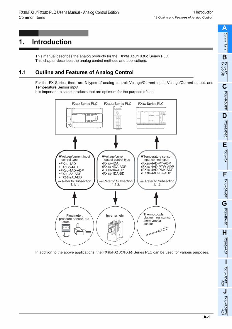
1 Introduction1.1 Outline and Features of Analog Control
FX3G/FX3U/FX3UC PLC User's Manual - Analog Control EditionCommon Items
A
Comm
on Items
B
FX3U-4ADFX3UC-4AD
C
FX3U-4AD-ADP
D
FX3G-2AD-BD
E
FX3U-4DA
F
FX3U-4DA-ADP
G
FX3G-1DA-BD
H
FX3U-3A-ADP
I
FX3U-4AD-PT -ADP
J
FX3U-4AD-PTW -AD
1. Introduction
This manual describes the analog products for the FX3G/FX3U/FX3UC Series PLC.This chapter describes the analog control methods and applications.
1.1 Outline and Features of Analog Control
For the FX Series, there are 3 types of analog control: Voltage/Current input, Voltage/Current output, andTemperature Sensor input.It is important to select products that are optimum for the purpose of use.
In addition to the above applications, the FX3U/FX3UC/FX3G Series PLC can be used for various purposes.
Thermocouple,platinum resistancethermometersensor
→ Refer to Subsection1.1.3.
Temperature sensor input control type
FX3UC Series PLC
Flowmeter,pressure sensor, etc.
Voltage/current input control type
•FX3U-4AD-ADP
•FX3U-4AD•FX3UC-4AD
•FX3U-3A-ADP•FX3G-2AD-BD
→ Refer to Subsection1.1.1.
•FX3U-4DAFX3U-4DA-ADP•
•FX3U-3A-ADP•FX3G-1DA-BD
Voltage/current output control type
Inverter, etc.
→ Refer to Subsection1.1.2.
FX3U Series PLC FX3G Series PLC
•FX3U-4AD-PT-ADP•FX3U-4AD-PTW-ADP•FX3U-4AD-PNK-ADP•FX3U-4AD-TC-ADP• 3U
A-1
P
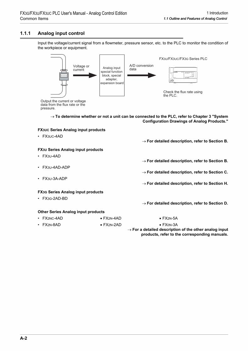
1 Introduction1.1 Outline and Features of Analog Control
FX3G/FX3U/FX3UC PLC User's Manual - Analog Control EditionCommon Items 1.1 Outline and Features of Analog Control
1.1.1 Analog input control
Input the voltage/current signal from a flowmeter, pressure sensor, etc. to the PLC to monitor the condition ofthe workpiece or equipment.
→ To determine whether or not a unit can be connected to the PLC, refer to Chapter 3 "SystemConfiguration Drawings of Analog Products."
FX3UC Series Analog input products• FX3UC-4AD
→ For detailed description, refer to Section B.
FX3U Series Analog input products• FX3U-4AD
→ For detailed description, refer to Section B.• FX3U-4AD-ADP
→ For detailed description, refer to Section C.• FX3U-3A-ADP
→ For detailed description, refer to Section H.
FX3G Series Analog input products• FX3G-2AD-BD
→ For detailed description, refer to Section D.
Other Series Analog input products• FX2NC-4AD • FX2N-4AD • FX2N-5A• FX2N-8AD • FX2N-2AD • FX0N-3A
→ For a detailed description of the other analog inputproducts, refer to the corresponding manuals.
Voltage orcurrent
Analog input
special function
block, special
adapter,
expansion board
A/D conversiondata
FX3U/FX3UC Series PLC
Output the current or voltagedata from the flux rate or thepressure.
Check the flux rate usingthe PLC.
/FX3G
A-2

1 Introduction1.1 Outline and Features of Analog Control
FX3G/FX3U/FX3UC PLC User's Manual - Analog Control EditionCommon Items
A
Comm
on Items
B
FX3U-4ADFX3UC-4AD
C
FX3U-4AD-ADP
D
FX3G-2AD-BD
E
FX3U-4DA
F
FX3U-4DA-ADP
G
FX3G-1DA-BD
H
FX3U-3A-ADP
I
FX3U-4AD-PT -ADP
J
FX3U-4AD-PTW -AD
1.1.2 Analog output control
Output the voltage/current signal from the PLC to an inverter, etc. to control the inverter frequency, etc.
→ To determine whether or not a unit can be connected to the PLC, refer to Chapter 3 "SystemConfiguration Drawings of Analog Products."
Analog output products for FX3U Series• FX3U-4DA
→ For detailed description, refer to Section E.• FX3U-4DA-ADP
→ For detailed description, refer to Section F.• FX3U-3A-ADP
→ For detailed description, refer to Section H.
Analog output products for FX3G Series• FX3G-1DA-BD
→ For detailed description, refer to Section G.
Other Series Analog output products• FX2NC-4DA • FX2N-2DA • FX0N-3A• FX2N-4DA • FX2N-5A
→ For a detailed description of the other analog outputproducts, refer to the corresponding manuals.
Voltage orcurrent
Analog output
special function
block, special
adapter,
expansion board
D/A conversiondata
Output the frequency datafrom the PLC.
The frequency will bechanged depending onthe input voltage/current.
Inverter, etc.FX3U/FX3UC Series PLC/FX3G
A-3
P

1 Introduction1.1 Outline and Features of Analog Control
FX3G/FX3U/FX3UC PLC User's Manual - Analog Control EditionCommon Items 1.1 Outline and Features of Analog Control
1.1.3 Temperature sensor input control
Use the PLC to check the workpiece/machine temperature measured with a thermocouple or platinumresistance thermometer sensor.
→ To determine whether or not a unit can be connected to the PLC, refer to Chapter 3 "SystemConfiguration Drawings of Analog Products."
FX3U Series Temperature sensor input products• FX3U-4AD-PT-ADP
→ For detailed description, refer to Section I.• FX3U-4AD-PTW-ADP
→ For detailed description, refer to Section J.• FX3U-4AD-PNK-ADP
→ For detailed description, refer to Section K.• FX3U-4AD-TC-ADP
→ For detailed description, refer to Section L.• FX3U-4LC
→ For detailed description, refer to the FX3U-4LC User’s Manual.
Other Series Temperature sensor input products• FX2N-8AD • FX2N-2LC• FX2N-4AD-TC • FX2N-4AD-PT
→ For a detailed description of the other temperature sensor input products, refer to thecorresponding manuals.
Temperature data(Analog data) Temperature
sensor input,special functionblock or special
adapter
Temperature data(Digital value)
Check the temperatureusing the PLC.
Measure thetemperature of theequipment.
FX3U/FX3UC Series PLC/FX3G
A-4

2 Description of Analog Products2.1 Types of Analog Products
FX3G/FX3U/FX3UC PLC User's Manual - Analog Control EditionCommon Items
A
Comm
on Items
B
FX3U-4ADFX3UC-4AD
C
FX3U-4AD-ADP
D
FX3G-2AD-BD
E
FX3U-4DA
F
FX3U-4DA-ADP
G
FX3G-1DA-BD
H
FX3U-3A-ADP
I
FX3U-4AD-PT -ADP
J
FX3U-4AD-PTW -AD
2. Description of Analog Products
2.1 Types of Analog Products
Analog input/output products are required to perform analog control using the FX Series PLC.There are 3 types of input/output products: the expansion board, special adapter and the special functionblock.Subsequent subsections explain differences among analog products.
2.1.1 Expansion board
The analog expansion board uses PLC devices to send/receive data to/from the PLC.
1. FX3G Series PLC• Connect analog expansion boards to option connectors of an FX3G PLC.
• Up to 2*1 analog expansion boards can be connected.
→ For a detailed description of the system configuration, refer to the PLC User’s Manual - HardwareEdition.
*1. Only 1 analog special adapter can be connected to the FX3G Series PLC(14-point and 24-point type).When two analog expansion boards are connected to the FX3G Series PLC(40-point or 60-point type),analog special adapters are not available in the main unit.
PLC
Analog
expansion board
A-5
P

2 Description of Analog Products2.1 Types of Analog Products
FX3G/FX3U/FX3UC PLC User's Manual - Analog Control EditionCommon Items 2.1 Types of Analog Products
2.1.2 Special adapter
The analog special adapter uses PLC devices to send/receive data to/from the PLC.
1. FX3U Series PLC• Connect the special adapter(s) to the left side of the FX3U Series PLC.• An expansion board is needed to connect the special adapter(s).• Up to 4 analog special adapters can be connected.• When using the high-speed input/output special adapter(s), be sure to connect the high-speed input/output
special adapter(s) first, and then connect the analog special adapter(s).
→ For a detailed description of the system configuration, refer to the PLC User’s Manual - HardwareEdition.
2. FX3UC (D, DS, DSS) Series PLC• Connect the special adapter(s) to the left side of the FX3UC (D, DS, DSS) Series PLC.• Up to 4 analog special adapters can be connected.
→ For a detailed description of the system configuration, refer to the PLC User’s Manual - HardwareEdition.
PO ER
FX3U-4AD-ADP
WPOWER
FX3U-4AD-ADP
POWER
FX3U-4AD-ADP
POWER
FX3U-4AD-ADP
RD
RDA
RDB
SDA
SDB
SG
SD
FX3U-***-BD
Up to 4 Analog adapters can be connected.
PLC
"***" represents "422", "232","485", "8AV", "CNV", or "USB."
Analog special adapters Expansion board
High-speedinput/output
special adapters
PO ER
FX3U-4AD-ADPWPOWER
FX3U-4AD-ADPPOWER
FX3U-4AD-ADPPOWER
FX3U-4AD-ADP
Up to 4 Analog adapters can be connected.
PLCAnalog special adapters
A-6
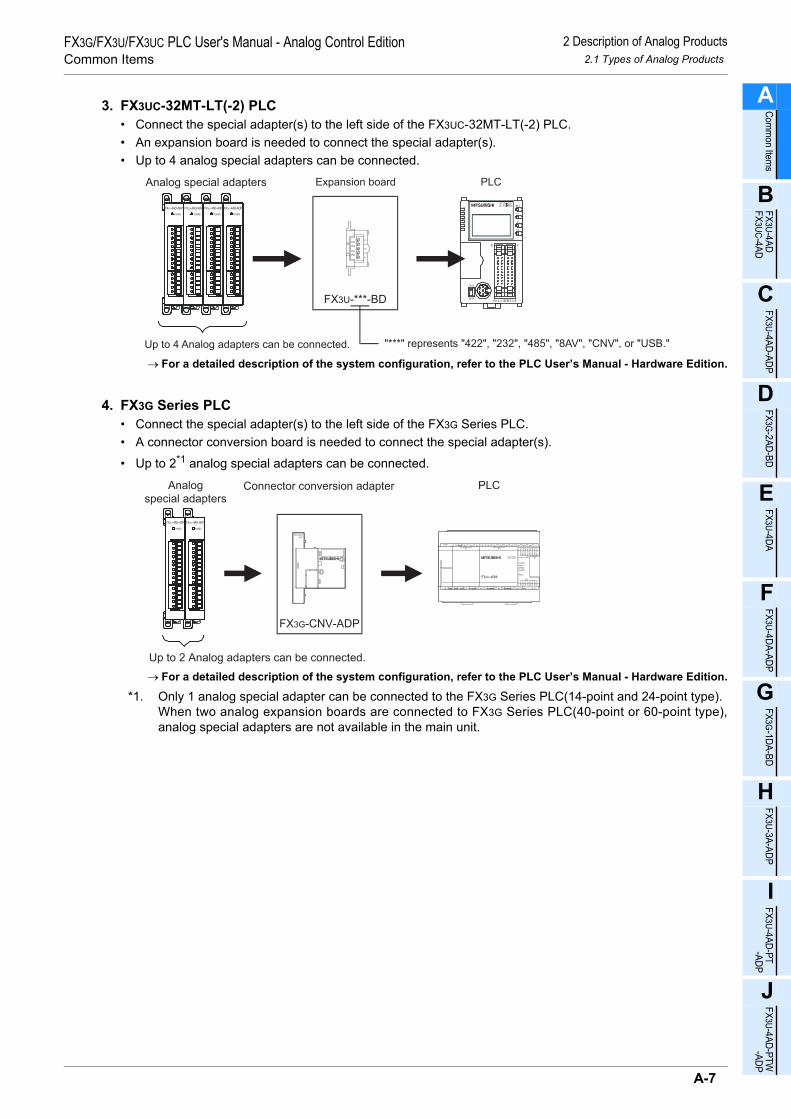
2 Description of Analog Products2.1 Types of Analog Products
FX3G/FX3U/FX3UC PLC User's Manual - Analog Control EditionCommon Items
A
Comm
on Items
B
FX3U-4ADFX3UC-4AD
C
FX3U-4AD-ADP
D
FX3G-2AD-BD
E
FX3U-4DA
F
FX3U-4DA-ADP
G
FX3G-1DA-BD
H
FX3U-3A-ADP
I
FX3U-4AD-PT -ADP
J
FX3U-4AD-PTW -AD
3. FX3UC-32MT-LT(-2) PLC• Connect the special adapter(s) to the left side of the FX3UC-32MT-LT(-2) PLC.• An expansion board is needed to connect the special adapter(s).• Up to 4 analog special adapters can be connected.
→ For a detailed description of the system configuration, refer to the PLC User’s Manual - Hardware Edition.
4. FX3G Series PLC• Connect the special adapter(s) to the left side of the FX3G Series PLC.• A connector conversion board is needed to connect the special adapter(s).
• Up to 2*1 analog special adapters can be connected.
→ For a detailed description of the system configuration, refer to the PLC User’s Manual - Hardware Edition.
*1. Only 1 analog special adapter can be connected to the FX3G Series PLC(14-point and 24-point type).When two analog expansion boards are connected to FX3G Series PLC(40-point or 60-point type),analog special adapters are not available in the main unit.
PO ER
FX3U-4AD-ADP
WPOWER
FX3U-4AD-ADP
POWER
FX3U-4AD-ADP
POWER
FX3U-4AD-ADP
RD
RDA
RDB
SDA
SDB
SG
SD
FX3U-***-BD
Up to 4 Analog adapters can be connected.
PLC
"***" represents "422", "232", "485", "8AV", "CNV", or "USB."
Analog special adapters Expansion board
Analog
special adaptersConnector conversion adapter PLC
Up to 2 Analog adapters can be connected.
FX3G-CNV-ADP
A-7
P

2 Description of Analog Products2.1 Types of Analog Products
FX3G/FX3U/FX3UC PLC User's Manual - Analog Control EditionCommon Items 2.1 Types of Analog Products
2.1.3 Special function block
The special function block uses buffer memory (BFM) to send/receive data to/from the PLC.
1. FX3U Series PLC• Connect the special function block(s) to the right side of the FX3U Series PLC.• Up to 8 special function blocks can be connected.
→ For a detailed description of the system configuration, refer to the PLC User’s Manual - Hardware Edition.
2. FX3UC Series PLC• Connect the special function block(s) to the right side of the FX3UC Series PLC.• In some cases, FX2NC-CNV-IF or FX3UC-1PS-5V may be needed for connection.• Up to 8*1 special function blocks can be connected.
*1. Up to 7 special function units/blocks can be connected to the FX3UC-32MT-LT(-2) PLC.
Select either FX3UC-1PS-5V or FX2NC-CNV-IF considering the current components consumption.→ For a detailed description of the system configuration, refer to the PLC User’s Manual - Hardware Edition.
3. FX3G Series PLC• Connect the special function block(s) to the right side of the FX3G Series PLC.• Up to 8 special function blocks can be connected.
→ For a detailed description of the system configuration, refer to the PLC User's Manual - Hardware Edition.
Up to 8 special function units/blocks can beconnected (excluding the special adapters).
PLC Analog special function blockfor FX3U, FX2N and FX0N
Up to 8*1 special function units/blocks can be connected (excluding the special adapters).
PLC FX3UC or FX2NC Analogspecial function block FX3UC-1PS-5V
orFX2NC-CNV-IF
FX3U, FX2N or FX0N Analogspecial function block
Up to 8 special function units/blocks can beconnected (excluding the special adapters).
PLC Analog special function blockfor FX3U and FX2N
A-8

2 Description of Analog Products2.2 List of Analog Product Models
FX3G/FX3U/FX3UC PLC User's Manual - Analog Control EditionCommon Items
A
Comm
on Items
B
FX3U-4ADFX3UC-4AD
C
FX3U-4AD-ADP
D
FX3G-2AD-BD
E
FX3U-4DA
F
FX3U-4DA-ADP
G
FX3G-1DA-BD
H
FX3U-3A-ADP
I
FX3U-4AD-PT -ADP
J
FX3U-4AD-PTW -AD
2.2 List of Analog Product Models
The analog input/output products compatible with the FX3U/FX3UC/FX3G Series PLC are described below:
2.2.1 Expansion board
• FX3G Series PLC
2.2.2 Special adapter
Type No. of channels Range Resolution Function Refer-
ence
Voltage/current input
FX3G-2AD-BD 2chVoltage: 0V to 10V DC 2.5mV(12bits) Combined use of voltage and
current inputs is possible. DCurrent: 4mA to 20mA DC 8µA(11bits)
Voltage/current output
FX3G-1DA-BD 1chVoltage: 0V to 10V DC 2.5mV(12bits)
Voltage and current output. GCurrent: 4mA to 20mA DC 8µA(11bits)
Type No. of channels Range Resolution Function Refer-
ence
Voltage/current input
FX3U-4AD-ADP 4chVoltage: 0V to 10V DC 2.5mV(12bits) Combined use of voltage and
current inputs is possible. CCurrent: 4mA to 20mA DC 10µA(11bits)
Voltage/current output
FX3U-4DA-ADP 4chVoltage: 0V to 10V DC 2.5mV(12bits) Combined use of voltage and
current outputs is possible. FCurrent: 4mA to 20mA DC 4µA(12bits)
Voltage/current input/output mixture
FX3U-3A-ADP
Input2ch
Voltage: 0V to 10V DC 2.5mV(12bits)Combined use of voltage/current inputs and voltage/current output is possible.
HCurrent: 4mA to 20mA DC 5µA(12bits)
Output1ch
Voltage: 0V to 10V DC 2.5mV(12bits)
Current: 4mA to 20mA DC 4µA(12bits)
Temperature sensor input
FX3U-4AD-PT-ADP 4ch Pt100: -50°C to +250°C 0.1°C
Compatible with the platinum resistance thermometer sensor (Pt100).The product can be switched between "Centigrade" and "Fahrenheit."
I
FX3U-4AD-PTW-ADP 4ch Pt100: -100°C to +600°C 0.2°C to 0.3°C
Compatible with the platinum resistance thermometer sensor (Pt100).The product can be switched between "Centigrade" and "Fahrenheit."
J
FX3U-4AD-PNK-ADP 4ch
Pt1000: -50°C to +250°C
0.1°C
Compatible with the input sensor (Pt1000 and Ni1000).The product can be switched between "Centigrade" and "Fahrenheit."
KNi1000: -45°C to +115°C
FX3U-4AD-TC-ADP 4ch
Type K: -100°C to +1000°C 0.4°CCompatible with thermocouple types K and J.The product can be switched between "Centigrade" and "Fahrenheit."
LType J: -100°C to +600°C 0.3°C
A-9
P

2 Description of Analog Products2.2 List of Analog Product Models
FX3G/FX3U/FX3UC PLC User's Manual - Analog Control EditionCommon Items 2.2 List of Analog Product Models
2.2.3 Special function block
Type No. of channels Range Resolution Function Refer-
enceVoltage/current input
FX3U-4AD*1 4ch
Voltage: -10V to +10V DC
0.32mV (with sign, 16 bits)
Combined use of voltage and current inputs is possible. The offset/gain can be adjusted.*3The sampling function is incorporated.
BCurrent: -20mA to +20mA DC
1.25µA (with sign, 15 bits)
FX3UC-4AD*2 4ch
Voltage: -10V to +10V DC
0.32mV (with sign, 16 bits)
Combined use of voltage and current inputs is possible. The offset/gain can be adjusted.*3The sampling function is incorporated.
BCurrent: -20mA to +20mA DC
1.25µA (with sign, 15 bits)
FX2NC-4AD*2 4ch
Voltage: -10V to +10V DC
0.32mV (with sign, 16 bits)
Combined use of voltage and current inputs is possible.The offset/gain can be adjusted.*3The sampling function is incorporated.
*5Current: -20mA to +20mA DC
1.25µA (with sign, 15 bits)
FX2N-8AD*1 8ch
Voltage: -10V to +10V DC
0.63mV (with sign, 15 bits)
Combined use of voltage, current, and thermocouple is possible. The offset/gain can be adjusted.*3The sampling function is incorporated.
*5Current: -20mA to +20mA DC
2.5µA (with sign, 14 bits)
FX2N-4AD*1 4ch
Voltage: -10V to +10V DC
5mV (with sign, 12 bits) Combined use of voltage and
current inputs is possible.The offset/gain can be adjusted.
*5Current:-20mA to +20mA DC
10µA (with sign, 11 bits)
FX2N-2AD*1 2ch
Voltage: 0V to 10V DC
2.5mV (12bits)
Combined use of voltage and current inputs is impossible.The offset/gain can be adjusted.(Common to 2 input channels)
*5Current: 4mA to 20mA DC
4µA (12bits)
Voltage/current output
FX3U-4DA*1 4ch
Voltage: -10V to +10V DC
0.32mV (with sign, 16 bits) Combined use of voltage and
current outputs is possible.*4The offset/gain can be adjusted.
ECurrent: 0mA to 20mA DC
0.63µA (15bits)
FX2NC-4DA*2 4ch
Voltage: -10V to +10V DC
5mV (with sign, 12 bits) Combined use of voltage and
current outputs is possible.The offset/gain can be adjusted.
*5Current: 0mA to 20mA DC
20µA (10bits)
FX2N-4DA*1 4ch
Voltage: -10V to +10V DC
5 mV (with sign, 12 bits) Combined use of voltage and
current outputs is possible.The offset/gain can be adjusted.
*5Current: 0mA to 20mA DC
20µA (10bits)
FX2N-2DA*1 2ch
Voltage: 0V to 10V DC
2.5 mV (12 bits) Combined use of voltage and
current outputs is possible.The offset/gain can be adjusted.
*5Current: 4mA to 20mA DC
4µA (12bits)
*1. To connect this block to the FX3UC Series PLC, either the FX2NC-CNV-IF or FX3UC-1PS-5V is required.*2. Connectable with the FX3UC Series PLC only.*3. The offset and gain of the FX3U-4AD, FX3UC-4AD, FX2NC-4AD and FX2N-8AD cannot be adjusted for
channels using the analog value direct indication mode.*4. The offset and gain of the FX3U-4DA cannot be adjusted for channels using the analog value mV (or µA)
specification mode.*5. Refer to the instruction manual of the respective product.
A-10

2 Description of Analog Products2.2 List of Analog Product Models
FX3G/FX3U/FX3UC PLC User's Manual - Analog Control EditionCommon Items
A
Comm
on Items
B
FX3U-4ADFX3UC-4AD
C
FX3U-4AD-ADP
D
FX3G-2AD-BD
E
FX3U-4DA
F
FX3U-4DA-ADP
G
FX3G-1DA-BD
H
FX3U-3A-ADP
I
FX3U-4AD-PT -ADP
J
FX3U-4AD-PTW -AD
Voltage/current input/output mixture
FX2N-5A*1
Input4ch
Voltage: -10V to +10V DC
0.32mV (with sign, 16 bits) Combined use of voltage and
current is possible.The offset/gain can be adjusted.*3The scaling function is incorporated.
*2
Current: -20mA to +20mA DC
1.25µA (with sign, 15 bits)
Output1ch
Voltage: -10V to +10V DC
5mV (with sign, 12 bits)
Current: 0mA to 20mA DC
20µA (10bits)
FX0N-3A*1, *4
Input2ch
Voltage: 0V to 10V DC
40mV (8bits)
The input format is common to 2 channels.The offset/gain can be adjusted.(Common to 2 input channels)
*2
Current: 4mA to 20mA DC
64µA (8bits)
Output1ch
Voltage: 0V to 10V DC
40mV (8bits)
Current: 4mA to 20mA DC
64µA (8bits)
Temperature sensor input
FX2N-8AD*1 8ch
Type K: -100°C to +1200°C
0.1°C
Combined use of voltage, current, and thermocouple is possible.Compatible with thermocouple types K, J, and T.The unit can be switched between "Centigrade" and "Fahrenheit."The sampling function is incorporated.
*2
Type J: -100°C to +600°C
Type T: -100°C to +350°C
FX2N-4AD-TC*1 4ch
Type K: -100°C to +1200°C 0.4°C Compatible with thermocouple
types K and J.The unit can be switched between "Centigrade" and "Fahrenheit."
*2Type J: -100°C to +600°C 0.3°C
FX2N-4AD-PT*1 4ch Pt100:-100°C to +600°C 0.2°C to 0.3°C
Compatible with the platinum resistance thermometer sensor (Pt100 or JPt100).The unit can be switched between "Centigrade" and "Fahrenheit."
*2
FX3U-4LC*1 4ch
Example:Type K:-100°C to +1300°CExample:Pt100:-200°C to +600°C
0.1°C or 1°C(Depends on the sensor input range.)
Compatible with thermocouple types K, J, R, S, E, T, B, N, PL II, W5Re/W26Re, U, and L.Compatible with the platinum resistance thermometer sensor (Pt1000, Pt100, and JPt100).The unit can be switched between "Centigrade" and "Fahrenheit."Compatible with the micro voltage input.The temperature adjustment function (PID operation, etc.) is incorporated.The peak disconnection detection function is incorporated.(A CT sensor is needed.)
*2
*1. To connect this block to the FX3UC Series PLC, either the FX2NC-CNV-IF or FX3UC-1PS-5V is required.*2. Refer to the instruction manual of the respective product.*3. The offset and gain of the FX2N-5A cannot be adjusted for channels using the analog value direct
indication mode or analog value mV (or µA) specification mode.*4. The FX0N-3A cannot be connected to the FX3G Series PLC.
Type No. of channels Range Resolution Function Refer-
ence
A-11
P

2 Description of Analog Products2.2 List of Analog Product Models
FX3G/FX3U/FX3UC PLC User's Manual - Analog Control EditionCommon Items 2.2 List of Analog Product Models
Type No. of channels Range Resolution Function Refer-
enceTemperature sensor input
FX2N-2LC*1 2ch
Example:Type K: -600°C to +1300°C
0.1°C or 1°C (Depends on the sensor input range.)
Compatible with thermocouple types K, J, R, S, E, T, B, N, PL II, W5Re/W26Re, U, and L.Compatible with the platinum resistance thermometer sensor (Pt100, JPt100).The unit can be switched between "Centigrade" and "Fahrenheit."The temperature adjustment function (PID operation, etc.) is incorporated.The peak disconnection detection function is incorporated.(A CT sensor is needed.)
*2Example:Pt100: -200°C to +600°C
*1. To connect this block to the FX3UC Series PLC, either the FX2NC-CNV-IF or FX3UC-1PS-5V is required.*2. Refer to the instruction manual of the respective product.
A-12

3 System Configuration Drawings of Analog Products3.1 FX3U Series PLC
FX3G/FX3U/FX3UC PLC User's Manual - Analog Control EditionCommon Items
A
Comm
on Items
B
FX3U-4ADFX3UC-4AD
C
FX3U-4AD-ADP
D
FX3G-2AD-BD
E
FX3U-4DA
F
FX3U-4DA-ADP
G
FX3G-1DA-BD
H
FX3U-3A-ADP
I
FX3U-4AD-PT -ADP
J
FX3U-4AD-PTW -AD
3. System Configuration Drawings of Analog Products
This section shows drawings to describe the configuration of analog units for the FX3U/FX3UC/FX3G SeriesPLC.
3.1 FX3U Series PLC
3.1.1 Connection of special adapters
*1. An FX3U-232-BD, FX3U-485-BD, FX3U-422-BD, FX3U-USB-BD, FX3U-8AV-BD, or FX3U-CNV-BD isneeded to connect the special adapters.
R D
RDA
RDB
SDA
SDB
SG
S D
Up
to
4 a
na
log
sp
ecia
l a
da
pte
rs c
an
be
co
nn
ecte
d.
Analog input
• Flowmeter
• Pressure sensor
• Signal converter, etc.
Analog input
• Flowmeter
• Pressure sensor
• Signal converter, etc.
Analog output
• Inverter, etc.
Analog output
• Inverter, etc.
B C represent the connecting positions.
For a detailed installation description, refer to the following manual supplied withyour PLC.
Refer to the FX3U Series User's Manual - Hardware Edition.
FX3U-***-BD*1
B
European terminal block
FX3U Series
CAB
A
FX3U-4AD-ADP
FX3U-4DA-ADP
FX3U-3A-ADP
European terminal block
European terminal block
A
A
A
FX3U-4AD-TC-ADPFX3U-4AD-PNK-ADPFX3U-4AD-PT-ADPFX3U-4AD-PTW-ADP
European terminal block
A Temperature sensor
input
•
•
•
Thermocouple
(types K and J)
Resistance
thermometer
sensor (Pt1000 and
Ni1000) Platinum resistance
thermometer
sensor (Pt100)
and, ,
CTo connect special function blocks , refer to the next page.
A-13
P

3 System Configuration Drawings of Analog Products3.1 FX3U Series PLC
FX3G/FX3U/FX3UC PLC User's Manual - Analog Control EditionCommon Items 3.1 FX3U Series PLC
3.1.2 Connection of special function blocks
• For a detailed description of the connectable special function blocks and system configuration:→ Refer to the FX3U Series User's Manual - Hardware Edition.
The analog special function blocks shown in the table below can be connected to the FX3U Series PLC:
FX Series Type
Analog special function blocks for the FX3U
FX3U-4AD, FX3U-4DA, FX3U-4LC
Analog special function blocks for the FX2N
FX2N-8AD, FX2N-4AD, FX2N-2AD, FX2N-4DA, FX2N-2DA, FX2N-5A,FX2N-4AD-PT, FX2N-4AD-TC, FX2N-2LC
Analog special function blocks for the FX0N
FX0N-3A
Up
to 8
spe
cial
func
tion
bloc
ks c
an b
e co
nnec
ted.
Bor the expansion boardsATo connect the special adaptersrefer to the previous page.
,
FX3U Series
CA B
B C represent the connecting positions.For a detailed description of installation, refer to the following manualsupplied with your PLC. → Refer to the FX3U Series User's Manual - Hardware Edition.
A and, ,
Special functionblock for FX3U,FX2N and FX0N
Terminal block
Analog input• Flowmeter• Pressure sensor• Signal converter, etc.
Analog output• Inverter, etc.
Temperature sensorinput• Thermocouple• Platinum resistance thermometer sensor (Pt100)
C
A-14

3 System Configuration Drawings of Analog Products3.2 FX3UC Series PLC
FX3G/FX3U/FX3UC PLC User's Manual - Analog Control EditionCommon Items
A
Comm
on Items
B
FX3U-4ADFX3UC-4AD
C
FX3U-4AD-ADP
D
FX3G-2AD-BD
E
FX3U-4DA
F
FX3U-4DA-ADP
G
FX3G-1DA-BD
H
FX3U-3A-ADP
I
FX3U-4AD-PT -ADP
J
FX3U-4AD-PTW -AD
3.2 FX3UC Series PLC
3.2.1 Connection of special adapters
1. FX3UC (D, DS, DSS) Series PLC
European terminal block
European terminal block
European terminal block
European terminal block
Up
to
4 a
na
log
sp
ecia
l a
da
pte
rs c
an
be
co
nn
ecte
d.
Analog input
•Flowmeter
•Pressure sensor
•Signal converter, etc.
Analog input
•Flowmeter
•Pressure sensor
•Signal converter, etc.
Analog output
•Inverter, etc.
Analog output
•Inverter, etc.
C , represent the connecting positions.
For a detailed description of installation, refer to the following manual supplied with toyour PLC.
→ Refer to the FX3UC Series User's Manual - Hardware Edition.
A
FX3U-4AD-ADP
FX3U-4DA-ADP
FX3U-3A-ADP
Thermocouple
(types K and J)
A
A
A
A
•
Resistance
thermometer
sensor (Pt1000 and
Ni1000)
•
Platinum resistance
thermometer
sensor (Pt100)
•
CTo connect the special function blocks Drefer to Subsection 3.2.2-1.
or the conversion adapters ,A C1 D C2
FX3U-4AD-TC-ADPFX3U-4AD-PNK-ADPFX3U-4AD-PT-ADPFX3U-4AD-PTW-ADP
input
Temperature sensor
A-15
P

3 System Configuration Drawings of Analog Products3.2 FX3UC Series PLC
FX3G/FX3U/FX3UC PLC User's Manual - Analog Control EditionCommon Items 3.2 FX3UC Series PLC
2. FX3UC-32MT-LT(-2) PLC
*1. An FX3U-232-BD, FX3U-485-BD, FX3U-422-BD, FX3U-USB-BD, FX3U-8AV-BD, or FX3U-CNV-BD isneeded to connect the special adapters.
RD
RDA
RDB
SDA
SDB
SG
SD
European terminal block
European terminal block
European terminal block
Up
to
4 a
na
log
sp
ecia
l a
da
pte
rs c
an
be
co
nn
ecte
d.
Analog input
•Flowmeter
•Pressure sensor
•Signal converter, etc.
Analog input
•Flowmeter
•Pressure sensor
•Signal converter, etc.
Analog output
•Inverter, etc.
Analog output
•Inverter, etc.
B C , , and represent the connecting positions.
For a detailed description of installation, refer to the following manual supplied with toyour PLC.
→ Refer to the FX3UC Series User's Manual - Hardware Edition.
FX3U-***-BD*1
B
A
FX3U-4AD-ADP
FX3U-4DA-ADP
FX3U-3A-ADP
A
A
A
CTo connect the special function blocks Drefer to Subsection 3.2.2-2.
or the conversion adapters ,A
BC1 D C2
European terminal block
A
FX3U-4AD-TC-ADPFX3U-4AD-PNK-ADPFX3U-4AD-PT-ADPFX3U-4AD-PTW-ADP
Temperature sensor
input
•
•
•
Thermocouple
(types K and J)
Resistance
thermometer
sensor (Pt1000 and
Ni1000) Platinum resistance
thermometer
sensor (Pt100)
A-16

3 System Configuration Drawings of Analog Products3.2 FX3UC Series PLC
FX3G/FX3U/FX3UC PLC User's Manual - Analog Control EditionCommon Items
A
Comm
on Items
B
FX3U-4ADFX3UC-4AD
C
FX3U-4AD-ADP
D
FX3G-2AD-BD
E
FX3U-4DA
F
FX3U-4DA-ADP
G
FX3G-1DA-BD
H
FX3U-3A-ADP
I
FX3U-4AD-PT -ADP
J
FX3U-4AD-PTW -AD
3.2.2 Connection of special function blocks
1. FX3UC (D, DS, DSS) Series PLC
• For a detailed description of special function block connectability and system configuration:→ Refer to the FX3UC Series User's Manual - Hardware Edition.
• Use the FX3UC-1PS-5V (extension power supply unit) if the capacity of the 5V DC power supply unit incorporated in the FX3UC Series PLC is deteriorated.
→ Refer to the FX3UC Series User's Manual - Hardware Edition.The analog special function blocks shown in the table below can be connected to the FX3UC Series PLC:
FX Series Type
Analog special function blocks for the FX3U FX3U-4AD, FX3U-4DA, FX3U-4LC
Analog special function blocks for the FX2NC FX2NC-4AD, FX2NC-4DA
Analog special function blocks for the FX2NFX2N-8AD, FX2N-4AD, FX2N-2AD, FX2N-4DA, FX2N-2DA,FX2N-5A, FX2N-4AD-PT, FX2N-4AD-TC, FX2N-2LC
Analog special function blocks for the FX0N FX0N-3A
C1A D C2
Up
to 8
spe
cial
func
tion
bloc
ks c
an b
e co
nnec
ted.
C represent the connecting positions.For a detailed description of installation, refer to the following manual supplied withto your PLC. → Refer to the FX3UC Series User's Manual - Hardware Edition.
A and, ,
C1
FX3UC-4AD
D
FX3UC-1PS-5V
Analog input•Flowmeter•Pressure sensor•Signal converter, etc.
Analog output•Inverter, etc.
Temperature sensorinput•Thermocouple•Platinum resistance thermometer sensor (Pt100)
European terminal block
C1
Special functionblock for FX2NC
European terminal block
C1
FX3UC-4AD
European terminal block
To connect the special adapters refer to Subsection 3.2.1-1.
C1
Special functionblock for FX2NC
European terminal block
Special functionblock for FX3U,FX2N and FX0N
Terminal block
D
FX2NC-CNV-IF
C1 C2or
D
C2
A
A-17
P
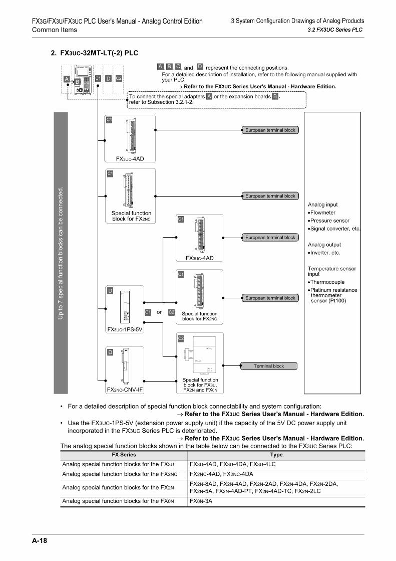
3 System Configuration Drawings of Analog Products3.2 FX3UC Series PLC
FX3G/FX3U/FX3UC PLC User's Manual - Analog Control EditionCommon Items 3.2 FX3UC Series PLC
2. FX3UC-32MT-LT(-2) PLC
• For a detailed description of special function block connectability and system configuration:→ Refer to the FX3UC Series User's Manual - Hardware Edition.
• Use the FX3UC-1PS-5V (extension power supply unit) if the capacity of the 5V DC power supply unit incorporated in the FX3UC Series PLC is deteriorated.
→ Refer to the FX3UC Series User's Manual - Hardware Edition.The analog special function blocks shown in the table below can be connected to the FX3UC Series PLC:
FX Series Type
Analog special function blocks for the FX3U FX3U-4AD, FX3U-4DA, FX3U-4LC
Analog special function blocks for the FX2NC FX2NC-4AD, FX2NC-4DA
Analog special function blocks for the FX2NFX2N-8AD, FX2N-4AD, FX2N-2AD, FX2N-4DA, FX2N-2DA,FX2N-5A, FX2N-4AD-PT, FX2N-4AD-TC, FX2N-2LC
Analog special function blocks for the FX0N FX0N-3A
C1A B D C2
Up
to 7
spe
cial
func
tion
bloc
ks c
an b
e co
nnec
ted.
B C represent the connecting positions.For a detailed description of installation, refer to the following manual supplied withyour PLC. → Refer to the FX3UC Series User's Manual - Hardware Edition.
A , and, ,
C1
FX3UC-4AD
D
FX3UC-1PS-5V
Analog input•Flowmeter•Pressure sensor•Signal converter, etc.
Analog output•Inverter, etc.
Temperature sensorinput•Thermocouple•Platinum resistance thermometer sensor (Pt100)
European terminal block
C1
Special functionblock for FX2NC
European terminal block
C1
FX3UC-4AD
European terminal block
Brefer to Subsection 3.2.1-2.
ATo connect the special adapters or the expansion boards ,
C1
Special functionblock for FX2NC
European terminal block
Special functionblock for FX3U,FX2N and FX0N
Terminal block
D
FX2NC-CNV-IF
C1 C2or
D
C2
A-18

3 System Configuration Drawings of Analog Products3.3 FX3G Series PLC
FX3G/FX3U/FX3UC PLC User's Manual - Analog Control EditionCommon Items
A
Comm
on Items
B
FX3U-4ADFX3UC-4AD
C
FX3U-4AD-ADP
D
FX3G-2AD-BD
E
FX3U-4DA
F
FX3U-4DA-ADP
G
FX3G-1DA-BD
H
FX3U-3A-ADP
I
FX3U-4AD-PT -ADP
J
FX3U-4AD-PTW -AD
3.3 FX3G Series PLC
3.3.1 Connection of expansion boards, special adapters
1. FX3G Series PLC (14-point, 24-point type)
and represent the connecting positions.
For a detailed description of installation, refer to the following manual
supplied with your PLC.
FX3G Series
Refer to the FX3G Series User's Manual - Hardware Edition.
European terminal block
European terminal block
European terminal block
Analog input
Flowmeter
Pressure sensor
Signal converter, etc.
Analog output
Inverter, etc.
Analog output
Inverter, etc.
Temperature sensor
input
Thermocouple
(types K and J)
Resistance
thermometer sensor
(Pt1000 and Ni1000)
Platinum resistance
thermometer
sensor (Pt100)
Up
to
1 a
nalo
g e
xp
an
sio
n b
oard
, an
alo
g s
pecia
l ad
ap
ter
can
be c
on
necte
d.
FX3G-CNV-ADP FX3U-4AD-ADP
1st
adapter
European terminal block
Analog input
Flowmeter
Pressure sensor
Signal converter, etc.
FX3U-3A-ADP
1st
adapter
Board A
Board A
European terminal blockAnalog output
Inverter, etc.
FX3G-1DA-BD
European terminal block
Analog input
Flowmeter
Pressure sensor
Signal converter, etc.
FX3G-2AD-BD
1st
adapter
1st
adapter
FX3U-4DA-ADP
FX3U-4AD-TC-ADP
FX3U-4AD-PNK-ADP
FX3U-4AD-PT-ADP
FX3U-4AD-PTW-ADP
A-19
P

3 System Configuration Drawings of Analog Products3.3 FX3G Series PLC
FX3G/FX3U/FX3UC PLC User's Manual - Analog Control EditionCommon Items 3.3 FX3G Series PLC
2. FX3G Series PLC (40-point, 60-point type)U
p t
o 2
an
alo
g e
xp
an
sio
n b
oa
rds,
an
alo
g s
pe
cia
l a
da
pte
rs c
an
be
co
nn
ecte
d.
Refer to the FX3G Series User's Manual - Hardware Edition.
, , and represent the connecting positions.
For a detailed description of installation, refer to the following manual supplied with to
your PLC.A
FX3G-2AD-BD
B
B
FX3G-1DA-BD
FX3G-2AD-BD
C
FX3G-1DA-BD
C
Only either or
can be used as 2nd.
European
terminal
block
European
terminal
block
European
terminal
block
European
terminal
block
Any one can be
selected.
FX3U-4AD-ADP
A
A
FX3U-4AD-TC-ADPFX3U-4AD-PNK-ADPFX3U-4AD-PT-ADP
FX3U-4AD-PTW-ADP
FX3U-4AD-ADP
A 1st
adapter
FX3U-4AD-TC-ADPFX3U-4AD-PNK-ADPFX3U-4AD-PT-ADP
FX3U-4AD-PTW-ADP
A 1st
adapter
FX3G-CNV-ADP
B
A B C
CBA
A C
European
terminal
block
European
terminal
block
European
terminal
block
European
terminal
block
European
terminal
block
Analog input
Flowmeter
Pressure sensor
Signal converter,
etc.
Analog input
Flowmeter
Pressure sensor
Signal converter,
etc.
Analog input
Flowmeter
Pressure sensor
Signal converter,
etc.
Analog output
Inverter, etc.
Analog output
Inverter, etc.
Temperature
sensor input
Thermocouple
(types K and J)
Resistance
thermometer
sensor (Pt1000
and Ni1000)
Platinum
resistance
thermometer
sensor (Pt100)
2nd
adapter
FX3U-4DA-ADP
A 2nd
adapter
2nd
adapter
FX3U-4DA-ADP
A 1st
adapter
European
terminal
block
Analog output
Inverter, etc.FX3U-3A-ADP
A 2nd
adapter
FX3U-3A-ADP
A 1st
adapter
European
terminal
block
European
terminal
block
Board A
Board B
Board B
Board A
A-20

3 System Configuration Drawings of Analog Products3.3 FX3G Series PLC
FX3G/FX3U/FX3UC PLC User's Manual - Analog Control EditionCommon Items
A
Comm
on Items
B
FX3U-4ADFX3UC-4AD
C
FX3U-4AD-ADP
D
FX3G-2AD-BD
E
FX3U-4DA
F
FX3U-4DA-ADP
G
FX3G-1DA-BD
H
FX3U-3A-ADP
I
FX3U-4AD-PT -ADP
J
FX3U-4AD-PTW -AD
3.3.2 Connection of special function blocks
• For a detailed description of the connectable special function blocks and system configuration:→ Refer to the FX3G Series User's Manual - Hardware Edition.
The analog special function blocks shown in the table below can be connected to the FX3G Series PLC:
FX Series Type
Analog special function blocks for the FX3U
FX3U-4AD, FX3U-4DA, FX3U-4LC
Analog special function blocks for the FX2N
FX2N-8AD, FX2N-4AD, FX2N-2AD, FX2N-4DA, FX2N-2DA, FX2N-5A,FX2N-4AD-PT, FX2N-4AD-TC, FX2N-2LC
Up
to
8 s
pe
cia
l fu
nctio
n b
locks c
an
be
co
nn
ecte
d.
or the connector conversionATo connect the special adapters
adapter
FX3G Series
CAB
B C represent the connecting positions.
For a detailed description of installation, refer to the following manualsupplied with your PLC.
→ Refer to the FX3G Series User's Manual - Hardware Edition.
A and, ,
Special functionblock for FX3U
and FX2N
Terminal block
Analog input
• Flowmeter
• Pressure sensor
• Signal converter, etc.
Analog output
• Inverter, etc.
Temperature sensorinput
• Thermocouple
C
B , refer to the previous page.
A-21
P

4 Comparison of Performance Specifications4.1 Analog Input
FX3G/FX3U/FX3UC PLC User's Manual - Analog Control EditionCommon Items 4.1 Analog Input
4. Comparison of Performance Specifications
The analog product performance specifications are shown in the following tables. Select the optimal productfor your equipment.
4.1 Analog Input
4.1.1 FX3U-4AD-ADP
SpecificationsFX3U-4AD-ADP
Voltage input Current input
Number of input points 4ch
Analog input range0V to 10V DC
(Input resistance: 194 kΩ)4mA to 20mA DC
(Input resistance: 250 Ω)
Absolute maximum input -0.5V,+15V -2mA,+30mA
OffsetImpossible to change Impossible to change
Gain
Digital output 12 bits, binary 11 bits, binary
Resolution 2.5mV(10V×1/4000) 10µA(16mA×1/1600)
Ove
rall
accu
racy Ambient temperature
:25±5°C ±0.5%(±50mV) for 10V full scale ±0.5%(±80µA) for 16mA full scale
Ambient temperature:0 to 55°C ±1.0%(±100mV) for 10V full scale ±1.0%(±160µA) for 16mA full scale
Time required for A/D conversion
• FX3U/FX3UC Series PLC : 200µs (Data updated every scan time.)• FX3G Series PLC : 250µs (Data updated every scan time.)
Input characteristics
Insulation method• The photocoupler is used to insulate the analog input area from the PLC.• The DC/DC converter is used to insulate the power supply from the analog inputs.• Channels are not insulated from each other.
Number of I/O points occupied 0 point (This number is not related to the maximum I/O points of the PLC.)
0
4000
10V
4080
Analog input
Dig
ita
l o
utp
ut
10
.2V
0
1600
20mA
1640
Analog input
Dig
ital outp
ut
4mA
20.4
mA
A-22

4 Comparison of Performance Specifications4.1 Analog Input
FX3G/FX3U/FX3UC PLC User's Manual - Analog Control EditionCommon Items
A
Comm
on Items
B
FX3U-4ADFX3UC-4AD
C
FX3U-4AD-ADP
D
FX3G-2AD-BD
E
FX3U-4DA
F
FX3U-4DA-ADP
G
FX3G-1DA-BD
H
FX3U-3A-ADP
I
FX3U-4AD-PT -ADP
J
FX3U-4AD-PTW -AD
4.1.2 FX2N-2AD
*1. For FX2N-2AD, combined use of the voltage and current inputs is not possible.
*2. Use the adjustment volume to adjust FX2N-2AD.*3. Adjustment of the offset or gain value will change the resolution.
SpecificationsFX2N-2AD
Voltage input Current input
Number of input points 2ch
Analog input range*10V to 5V DC
0V to 10V DC(Input resistance: 200 kΩ)
4mA to 20mA DC(Input resistance: 250Ω)
Absolute maximum input -0.5V,+15V -2mA,+60mA
Offset If the digital value is "0":0V to 1V*2,*3 If the digital value is "0":0mA to 4mA*2,*3
GainIf the digital value is "4000":
5V to 10V*2,*3 If the digital value is "4000":20mA*2,*3
Digital output 12 bits, binary
Resolution 2.5mV(10V×1/4000)*3 4.00µA(16mA×1/4000)*3
Ove
rall
accu
racy Ambient temperature:
25±5°C - -
Ambient temperature:0 to 55°C ±1.0%(±100mV) for 10V full scale ±1.0%(±160µA) for 16mA full scale
Time required for A/D conversion
2.5ms × number of selected channels(Operation synchronized with sequence program)
Input characteristics
Insulation method• The photocoupler is used to insulate the analog input area from the PLC.• Channels are not insulated from each other.
Number of I/O points occupied 8 points (Taken from either the input or output points of the PLC.)
0
4000
10V
4095
Analog input
Dig
ital o
utpu
t
10.2
38V
4095
0
4000
20mAAnalog input
Dig
ital i
nput
4mA
20.3
80m
A
A-23
P

4 Comparison of Performance Specifications4.1 Analog Input
FX3G/FX3U/FX3UC PLC User's Manual - Analog Control EditionCommon Items 4.1 Analog Input
4.1.3 FX3U-4AD
*1. Adjustment of the offset or gain value will not affect the resolution. In the direct indication mode, however, the offset/gain cannot be adjusted.
*2. The offset and the gain should satisfy the following condition:1V ≤ (Gain - Offset)
*3. The offset and the gain should satisfy the following condition:3mA ≤ (Gain - Offset) ≤ 30mA
*4. The resolution and the input/output characteristics depend on the selected mode.*5. If 1 or more channels use the digital filter(s), the time required for A/D conversion will be
"5 ms × number of selected channels."
SpecificationsFX3U-4AD
Voltage input Current input
Number of input points 4ch
Analog input range -10V to +10V DC(Input resistance: 200 kΩ)
-20mA to +20mA DC4mA to 20mA DC
(Input resistance: 250 Ω)
Absolute maximum input ±15V ±30mA
Offset -10V to +9V*1,*2 -20mA to +17mA*1,*3
Gain -9V to +10V*1,*2 -17mA to +30mA*1,*3
Digital output With sign, 16 bits, binary With sign, 15 bits, binary
Resolution*4 0.32mV(20V×1/64000)2.5mV(20V×1/8000)
1.25µA(40mA×1/32000)5.00µA(40mA×1/8000)
Ove
rall
accu
racy Ambient temperature:
25±5°C ±0.3%(±60mV) for 20V full scale ±0.5%(±200µA) for 40mA full scaleSame accuracy for 4mA to 20mA input
Ambient temperature:0 to 55°C ±0.5%(±100mV) for 20V full scale ±1.0%(±400µA) for 40mA full scale
Same accuracy for 4mA to 20mA input
Time required for A/D conversion 500µs × number of selected channels*5
Input characteristics*4
Insulation method• The photocoupler is used to insulate the analog input area from the PLC.• The DC/DC converter is used to insulate the power supply from the analog inputs.• Channels are not insulated from each other.
Number of I/O points occupied 8 points (Taken from either the input or output points of the PLC.)
When the input mode is set to "0":
0
+32000
+10V
+10.
2V
+32640
-10V
-10.
2V
-32000-32640
When the input mode is set to "6":
0
+16000
+20mA-20mA
-16000
+16320
+20.
4mA
-16320
-20.
4mA
When the input mode is set to "3":
0
16000
20mA4mA
16400
20.4
mA
A-24
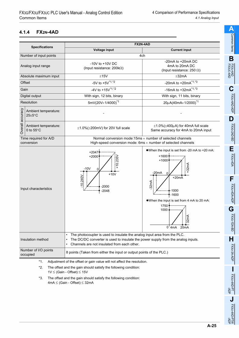
4 Comparison of Performance Specifications4.1 Analog Input
FX3G/FX3U/FX3UC PLC User's Manual - Analog Control EditionCommon Items
A
Comm
on Items
B
FX3U-4ADFX3UC-4AD
C
FX3U-4AD-ADP
D
FX3G-2AD-BD
E
FX3U-4DA
F
FX3U-4DA-ADP
G
FX3G-1DA-BD
H
FX3U-3A-ADP
I
FX3U-4AD-PT -ADP
J
FX3U-4AD-PTW -AD
4.1.4 FX2N-4AD
*1. Adjustment of the offset or gain value will not affect the resolution.
*2. The offset and the gain should satisfy the following condition:1V ≤ (Gain - Offset) ≤ 15V
*3. The offset and the gain should satisfy the following condition:4mA ≤ (Gain - Offset) ≤ 32mA
SpecificationsFX2N-4AD
Voltage input Current input
Number of input points 4ch
Analog input range -10V to +10V DC(Input resistance: 200kΩ)
-20mA to +20mA DC4mA to 20mA DC
(Input resistance: 250 Ω)
Absolute maximum input ±15V ±32mA
Offset -5V to +5V*1,*2 -20mA to +20mA*1,*3
Gain -4V to +15V*1,*2 -16mA to +32mA*1,*3
Digital output With sign, 12 bits, binary With sign, 11 bits, binary
Resolution 5mV(20V×1/4000)*1 20µA(40mA×1/2000)*1
Ove
rall
accu
racy Ambient temperature:
25±5°C - -
Ambient temperature:0 to 55°C ±1.0%(±200mV) for 20V full scale ±1.0%(±400µA) for 40mA full scale
Same accuracy for 4mA to 20mA input
Time required for A/D conversion
Normal conversion mode:15ms × number of selected channelsHigh-speed conversion mode: 6ms × number of selected channels
Input characteristics
Insulation method• The photocoupler is used to insulate the analog input area from the PLC.• The DC/DC converter is used to insulate the power supply from the analog inputs.• Channels are not insulated from each other.
Number of I/O points occupied 8 points (Taken from either the input or output points of the PLC.)
0
+2000
+10V
+10.
235V
+2047
-10V
-10.
240V
-2000-2048
When the input is set from -20 mA to +20 mA:
0
+1000
+20mA-20mA
-1000
+1600
+32m
A
-1600
-32m
A
When the input is set from 4 mA to 20 mA:
0
1000
20mA4mA
1750
32m
A
A-25
P

4 Comparison of Performance Specifications4.1 Analog Input
FX3G/FX3U/FX3UC PLC User's Manual - Analog Control EditionCommon Items 4.1 Analog Input
4.1.5 FX3UC-4AD
*1. Adjustment of the offset or gain value will not affect the resolution. In the direct indication mode, however, the offset/gain cannot be adjusted.
*2. The offset and the gain should satisfy the following condition:1V ≤ (Gain - Offset)
*3. The offset and the gain should satisfy the following condition:3mA ≤ (Gain - Offset) ≤ 30mA
*4. The resolution and the input/output characteristics depend on the selected mode.*5. If 1 or more channels use the digital filter(s), the time required for A/D conversion will be
"5 ms × number of selected channels."
SpecificationsFX3UC-4AD
Voltage input Current input
Number of input points 4ch
Analog input range -10V to +10V DC(Input resistance: 200 kΩ)
-20mA to +20mA DC4mA to 20mA DC
(Input resistance: 250 Ω)
Absolute maximum input ±15V ±30mA
Offset -10V to +9V*1,*2 -20mA to +17mA*1,*3
Gain -9V to +10V*1,*2 -17mA to +30mA*1,*3
Digital output With sign, 16 bits, binary With sign, 15 bits, binary
Resolution*4 0.32mV(20V×1/64000)2.5mV(20V×1/8000)
1.25µA(40mA×1/32000)5.00µA(40mA×1/8000)
Ove
rall
accu
racy Ambient temperature:
25±5°C ±0.3%(±60mV) for 20V full scale ±0.5%(±200µA) for 40mA full scaleSame accuracy for 4mA to 20mA input
Ambient temperature:0 to 55°C ±0.5%(±100mV) for 20V full scale ±1.0%(±400µA) for 40mA full scale
Same accuracy for 4mA to 20mA input
Time required for A/D conversion 500µs × number of selected channels*5
Input characteristics*4
Insulation method• The photocoupler is used to insulate the analog input area from the PLC.• The DC/DC converter is used to insulate the power supply from the analog inputs.• Channels are not insulated from each other.
Number of I/O points occupied 8 points (Taken from either the input or output points of the PLC.)
When the input mode is set to "0":
0
+32000
+10V
+10.
2V
+32640
-10V
-10.
2V
-32000-32640
When the input mode is set to "6":
0
+16000
+20mA-20mA
-16000
+16320
+20.
4mA
-16320
-20.
4mA
When the input mode is set to "3":
0
16000
20mA4mA
16400
20.4
mA
A-26

4 Comparison of Performance Specifications4.1 Analog Input
FX3G/FX3U/FX3UC PLC User's Manual - Analog Control EditionCommon Items
A
Comm
on Items
B
FX3U-4ADFX3UC-4AD
C
FX3U-4AD-ADP
D
FX3G-2AD-BD
E
FX3U-4DA
F
FX3U-4DA-ADP
G
FX3G-1DA-BD
H
FX3U-3A-ADP
I
FX3U-4AD-PT -ADP
J
FX3U-4AD-PTW -AD
4.1.6 FX2NC-4AD
*1. Adjustment of the offset or gain value will not affect the resolution. In the direct indication mode, however, the offset/gain cannot be adjusted.
*2. The offset and the gain should satisfy the following condition:1V ≤ (Gain - Offset)
*3. The offset and the gain should satisfy the following condition:3mA ≤ (Gain - Offset) ≤ 30mA
*4. The resolution and the input/output characteristics depend on the selected mode.*5. If 1 or more channels use the digital filter(s), the time required for A/D conversion will be
"5 ms × number of selected channels."
SpecificationsFX2NC-4AD
Voltage input Current input
Number of input points 4ch
Analog input range -10V to +10V DC(Input resistance: 200kΩ)
-20mA to +20mA DC4mA to 20mA DC
(Input resistance: 250 Ω)
Absolute maximum input ±15V ±30mA
Offset -10V to +9V*1,*2 -20mA to +17mA*1,*3
Gain -9V to +10V*1,*2 -17mA to +30mA*1,*3
Digital output With sign, 16 bits, binary With sign, 15 bits, binary
Resolution*4 0.32mV(20V×1/64000)2.5mV(20V×1/8000)
1.25µA(40mA×1/32000)5.00µA(40mA×1/8000)
Ove
rall
accu
racy Ambient temperature:
25±5°C ±0.3%(±60mV) for 20V full scale ±0.5%(±200µA) for 40mA full scaleSame accuracy for 4mA to 20mA input
Ambient temperature:0 to 55°C ±0.5%(±100mV) for 20V full scale ±1.0%(±400µA) for 40mA full scale
Same accuracy for 4mA to 20mA input
Time required for A/D conversion 1ms × number of selected channels*5
Input characteristics*4
Insulation method• The photocoupler is used to insulate the analog input area from the PLC.• The DC/DC converter is used to insulate the power supply from the analog inputs.• Channels are not insulated from each other.
Number of I/O points occupied 8 points (Taken from either the input or output points of the PLC.)
When the input mode is set to "0":
0
+32000
+10V
+10.
2V
+32640
-10V
-10.
2V
-32000-32640
When the input mode is set to "6":
0
+16000
20mA-20mA
-16000
+16320
+20.
4mA
-16320
-20.
4mA
When the input mode is set to "3":
0
16000
20mA4mA
16400
20.4
mA
A-27
P

4 Comparison of Performance Specifications4.1 Analog Input
FX3G/FX3U/FX3UC PLC User's Manual - Analog Control EditionCommon Items 4.1 Analog Input
4.1.7 FX2N-8AD
*1. Adjustment of the offset or gain value will not affect the resolution. In the direct indication mode, however, theoffset/gain cannot be adjusted.
*2. The offset and the gain should satisfy the following condition:1V ≤ (Gain - Offset)
*3. The offset and the gain should satisfy the following condition:3mA ≤ (Gain - Offset) ≤ 30mA
*4. The resolution and the input/output characteristics depend on the selected mode.*5. If 1 or more channels use the thermocouple input(s), the input voltage/current data conversion speed will be
"1 ms × number of selected channels."
SpecificationsFX2N-8AD
Voltage input Current input
Number of input points 8ch
Analog input range -10V to +10V DC(Input resistance: 200 kΩ)
-20mA to +20mA DC4mA to 20mA DC
(Input resistance: 250 Ω)
Absolute maximum input ±15V ±30mA
Offset -10V to +9V*1,*2 -20mA to +17mA*1,*3
Gain -9V to +10V*1,*2 -17mA to +30mA*1,*3
Digital output With sign, 15 bits, binary With sign, 14 bits, binary
Resolution*4 0.63mV(20V×1/32000)2.5mV(20V×1/8000)
2.50µA(40mA×1/16000)2.00µA(16mA×1/8000)
Ove
rall
accu
racy Ambient temperature:
25±5°C ±0.3%(±60mV) for 20V full scale ±0.3%(±120µA) for 40mA full scaleSame accuracy for 4mA to 20mA input
Ambient temperature:0 to 55°C ±0.5%(±100mV) for 20V full scale ±0.5%(±200µA) for 40mA full scale
Same accuracy for 4mA to 20mA input
Time required for A/D conversion 500µs × number of selected channels*5
Input characteristics*4
Insulation method• The photocoupler is used to insulate the analog input area from the PLC.• The DC/DC converter is used to insulate the power supply from the analog inputs.• Channels are not insulated from each other.
Number of I/O points occupied 8 points (Taken from either the input or output points of the PLC.)
When the input mode is set to "0":
0
+16000
+10V
+10.
2V
+16320
-10V
-10.
2V
-16000-16320
When the input mode is set to "6":
0
+8000
+20mA-20mA
-8000
+8160
+20.
4mA
Approx.-8160
-20.
4mA
When the input mode is set to "3":
0
8000
20mA4mA
8200
20.4
mA
A-28

4 Comparison of Performance Specifications4.1 Analog Input
FX3G/FX3U/FX3UC PLC User's Manual - Analog Control EditionCommon Items
A
Comm
on Items
B
FX3U-4ADFX3UC-4AD
C
FX3U-4AD-ADP
D
FX3G-2AD-BD
E
FX3U-4DA
F
FX3U-4DA-ADP
G
FX3G-1DA-BD
H
FX3U-3A-ADP
I
FX3U-4AD-PT -ADP
J
FX3U-4AD-PTW -AD
4.1.8 FX3G-2AD-BD
SpecificationsFX3G-2AD-BD
Voltage input Current input
Number of input points 2ch
Analog input range 0V to 10V DC(Input resistance: 198.7 kΩ)
4mA to 20mA DC(Input resistance: 250 Ω)
Absolute maximum input -0.5V. +15V -2mA, +30mA
OffsetImpossible to change Impossible to change
Gain
Digital output 12 bits, binary 11 bits, binary
Resolution 2.5mV(10V×1/4000) 8µA(16mA×1/2000)
Ove
rall
accu
racy Ambient temperature:
25±5°C ±0.5%(±50mV) for 10V full scale ±0.5%(±80µA) for 16mA full scale
Ambient temperature:0 to 55°C ±1.0%(±100mV) for 10V full scale ±1.0%(±160µA) for 16mA full scale
Time required for A/D conversion 180µs (Data updated every scan time.)
Input characteristics
Insulation method• The analog input area is not insulated from the PLC.• Channels are not insulated from each other.
Number of I/O points occupied 0 point (This number is not related to the maximum I/O points of the PLC.)
0
4000
10V 10.2V
4080
Analog input
Dig
ita
l o
utp
ut
0
2000
20mA 20.32mA
2040
Analog input
Dig
ita
l o
utp
ut
4mA
A-29
P

4 Comparison of Performance Specifications4.2 Analog Output
FX3G/FX3U/FX3UC PLC User's Manual - Analog Control EditionCommon Items 4.2 Analog Output
4.2 Analog Output
4.2.1 FX3U-4DA-ADP
SpecificationsFX3U-4DA-ADP
Voltage output Current output
Number of output points 4ch
Analog output range 0V to 10V DC(External load: 5k to 1MΩ)
4mA to 20mA DC(External load: 500Ω or less)
OffsetImpossible to change Impossible to change
Gain
Digital input 12 bits, binary
Resolution 2.5mV(10V×1/4000) 4µA(16mA×1/4000)
Ove
rall
accu
racy
Ambient temperature:25±5°C ±0.5%(±50mV) for 10V full scale ±0.5%(±80µA) for 16mA full scale
Ambient temperature:0 to 55°C ±1.0%(±100mV) for 10V full scale ±1.0%(±160µA) for 16mA full scale
Reference
If the external load resistance (Rs) is less than5kΩ, the accuracy increases as shown in thefollowing formula: (Increase: 100 mV per 1%) -
Time required for D/A conversion
• FX3U/FX3UC Series PLC : 200µs (Data updated every scan time.)• FX3G Series PLC : 250µs (Data updated every scan time.)
Output characteristics
Insulation method• The photocoupler is used to insulate the analog output area from the PLC.• The DC/DC converter is used to insulate the power supply from the analog inputs.• Channels are not insulated from each other.
Number of I/O points occupied 0 point (This number is not related to the maximum I/O points of the PLC.)
47×100Rs+47
-0.9(%)
0
10V
4000Digital input
Ana
log
outp
ut
4080
0
20mA
4000Digital input
Ana
log
outp
ut
4mA 4080
A-30

4 Comparison of Performance Specifications4.2 Analog Output
FX3G/FX3U/FX3UC PLC User's Manual - Analog Control EditionCommon Items
A
Comm
on Items
B
FX3U-4ADFX3UC-4AD
C
FX3U-4AD-ADP
D
FX3G-2AD-BD
E
FX3U-4DA
F
FX3U-4DA-ADP
G
FX3G-1DA-BD
H
FX3U-3A-ADP
I
FX3U-4AD-PT -ADP
J
FX3U-4AD-PTW -AD
4.2.2 FX2N-2DA
*1. Use the adjustment volume to adjust the FX2N-2DA.
*2. Adjustment of the offset or gain value will change the resolution.
SpecificationsFX2N-2DA
Voltage output Current output
Number of output points 2ch
Analog output range0V to 10V DC0V to 5V DC
(External load: 2k to 1MΩ)
4mA to 20mA DC(External load: 400Ω or less)
Offset*1,*2 If the digital value is "0":0V to 1V
If the digital value is "0":4mA
Gain*1,*2 If the digital value is "4000":5V to 10V
If the digital value is "4000":20mA
Digital output 12 bits, binary
Resolution 2.5mV(10V×1/4000)*2 4µA(16mA×1/4000)*2
Overall accuracy±0.1V ±0.16mA
Does not include any load fluctuation. -
Time required for D/A conversion
4ms × number of selected channels(Operation synchronized with sequence program)
Output characteristics
If the input data consists of 13 bits or more, only the lower 12 bits will be valid, and the other bits willbe ignored.
Insulation method• The photocoupler is used to insulate the analog output area from the PLC.• Channels are not insulated from each other.
Number of I/O points occupied 8 points (Taken from either the input or output points of the PLC.)
0
10V
4000Digital input
Ana
log
outp
ut
4095
0
20mA
4000Digital input
Ana
log
outp
ut4mA 40
95
A-31
P

4 Comparison of Performance Specifications4.2 Analog Output
FX3G/FX3U/FX3UC PLC User's Manual - Analog Control EditionCommon Items 4.2 Analog Output
4.2.3 FX3U-4DA
*1. Adjustment of the offset or gain value will not affect the resolution. In the analog value specificationmode, however, the offset/gain cannot be adjusted.
*2. The offset and the gain should satisfy the following condition:1V ≤ (Gain - Offset) ≤ 10V
*3. The offset and the gain should satisfy the following condition:3mA ≤ (Gain - Offset) ≤ 30mA
*4. Adjustment of the offset or gain value will not affect the resolution.
SpecificationsFX3U-4DA
Voltage output Current output
Number of output points 4ch
Analog output range -10V to +10V DC(External load: 1k to 1MΩ)
0mA to 20mA DC4mA to 20mA DC
(External load: 500Ω or less)
Offset -10V to +9V*1,*2 0mA to 17mA*1,*3
Gain -9V to +10V*1,*2 3mA to 30mA*1,*3
Digital input With sign, 16 bits, binary 15 bits, binary
Resolution 0.32mV(20V×1/64000)*4 0.63µA(20mA×1/32000)*4
Ove
rall
accu
racy Ambient temperature:
25±5°C ±0.3%(±60mV) for 20V full scale ±0.3%(±60µA) for 20mA full scaleSame accuracy for 4mA to 20mA output
Ambient temperature:0 to 55°C ±0.5%(±100mV) for 20V full scale ±0.5%(±100µA) for 20mA full scale
Same accuracy for 4mA to 20mA output
Reference Includes corrective function by load fluctuation. -
Time required for D/A conversion 1ms (The number of selected channels will not affect this value.)
Output characteristics
Insulation method• The photocoupler is used to insulate the analog output area from the PLC.• The DC/DC converter is used to insulate the power supply from the analog output.• Channels are not insulated from each other.
Number of I/O points occupied 8 points (Taken from either the input or output points of the PLC.)
0
+10V
+32000
-32000
-10V
When the output mode is set to "0":
+326
40
-326
40
+10.2V
-10.2V
When the output mode is "2":(The dotted line is for mode 3.)
0
20mA
32000Digital input
Ana
log
outp
ut
4mA 3264
0
20.4mA
A-32

4 Comparison of Performance Specifications4.2 Analog Output
FX3G/FX3U/FX3UC PLC User's Manual - Analog Control EditionCommon Items
A
Comm
on Items
B
FX3U-4ADFX3UC-4AD
C
FX3U-4AD-ADP
D
FX3G-2AD-BD
E
FX3U-4DA
F
FX3U-4DA-ADP
G
FX3G-1DA-BD
H
FX3U-3A-ADP
I
FX3U-4AD-PT -ADP
J
FX3U-4AD-PTW -AD
4.2.4 FX2N-4DA
*1. Adjustment of the offset or gain value will not affect the resolution.
*2. The offset and the gain should satisfy the following condition:11V ≤ (Gain - Offset) ≤ 15V
*3. The offset and the gain should satisfy the following condition:4mA ≤ (Gain - Offset) ≤ 32mA
SpecificationsFX2N-4DA
Voltage output Current output
Number of output points 4ch
Analog output range -10V to +10V DC(External load: 2k to 1MΩ)
0mA to 20mA DC4mA to 20mA DC
(External load: 500Ω or less)
Offset -5V to +5V*1,*2 -20mA to +20mA*1,*3
Gain 15 V or less, andGain - Offset ≥ 1V
32 mA or less, andGain - Offset ≥ 4mA
Digital output With sign, 12 bits, binary 10 bits, binary
Resolution 5mV(10V×1/2000)*1 20µA(20mA×1/1000)*1
Overall accuracy±1.0%(±200mV) for 20V full scale ±1.0%(±200µA) for 20mA full scale
Same accuracy for 4mA to 20mA output
Does not include any load fluctuation. -
Time required for D/A conversion 2.1 ms (The number of selected channels will not affect this value.)
Output characteristics
Insulation method• The photocoupler is used to insulate the analog input area from the PLC.• The DC/DC converter is used to insulate the power supply from the analog output.• Channels are not insulated from each other.
Number of I/O points occupied 8 points (Taken from either the input or output points of the PLC.)
0+2000
+10V
-10V
-2000
When the output mode is set to "0":
+204
7
-204
8
0 1000Digital input
4mA
Ana
log
outp
ut
20mA
When the output mode is "2":(The dotted line is for mode 1.)
1023
A-33
P

4 Comparison of Performance Specifications4.2 Analog Output
FX3G/FX3U/FX3UC PLC User's Manual - Analog Control EditionCommon Items 4.2 Analog Output
4.2.5 FX2NC-4DA
*1. Adjustment of the offset or gain value will not affect the resolution.
*2. The offset and the gain should satisfy the following condition:1V ≤ (Gain - Offset) ≤ 15V
*3. The offset and the gain should satisfy the following condition:4mA ≤ (Gain - Offset) ≤ 32mA
SpecificationsFX2NC-4DA
Voltage output Current output
Number of output points 4ch
Analog output range -10V to +10V DC(External load: 2k to 1MΩ)
0mA to 20mA DC4mA to 20mA DC
(External load: 500Ω or less)
Offset -5V to +5V*1,*2 -20mA to +20mA*1,*3
Gain -4V to +15V*1,*2 -16mA to +32mA*1,*3
Digital input With sign, 12 bits, binary 10 bits, binary
Resolution*1 5mV(20V×1/4000) 20µA(20mA×1/1000)
Ove
rall
accu
racy Ambient temperature:
25±5°C ±0.5%(±100mV) for 20V full scale ±0.5%(±100µA) for 20mA full scaleSame accuracy for 4mA to 20mA output
Ambient temperature:0 to 55°C ±1.0%(±200mV) for 20V full scale ±1.0%(±200µA) for 20mA full scale
Same accuracy for 4mA to 20mA output
Reference Does not include any load fluctuation. -
Time required for D/A conversion 2.1ms (The number of selected channels will not affect this value.)
Output characteristics
Insulation method• The photocoupler is used to insulate the analog output area from the PLC.• The DC/DC converter is used to insulate the power supply from the analog output.• Channels are not insulated from each other.
Number of I/O points occupied 8 points (Taken from either the input or output points of the PLC.)
0
+10V
+2000
-2000
-10V
When the output mode is set to "0":
+204
7
-204
8
When the output mode is "2":(The dotted line is for mode 1.)
0
20mA
1000Digital input
Ana
log
outp
ut
4mA 1023
A-34
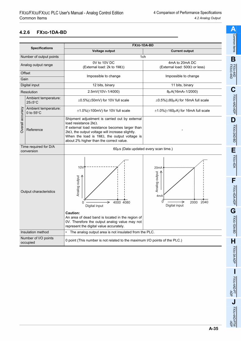
4 Comparison of Performance Specifications4.2 Analog Output
FX3G/FX3U/FX3UC PLC User's Manual - Analog Control EditionCommon Items
A
Comm
on Items
B
FX3U-4ADFX3UC-4AD
C
FX3U-4AD-ADP
D
FX3G-2AD-BD
E
FX3U-4DA
F
FX3U-4DA-ADP
G
FX3G-1DA-BD
H
FX3U-3A-ADP
I
FX3U-4AD-PT -ADP
J
FX3U-4AD-PTW -AD
4.2.6 FX3G-1DA-BD
SpecificationsFX3G-1DA-BD
Voltage output Current output
Number of output points 1ch
Analog output range 0V to 10V DC(External load: 2k to 1MΩ)
4mA to 20mA DC(External load: 500Ω or less)
OffsetImpossible to change Impossible to change
Gain
Digital input 12 bits, binary 11 bits, binary
Resolution 2.5mV(10V×1/4000) 8µA(16mA×1/2000)
Ove
rall
accu
racy
Ambient temperature:25±5°C ±0.5%(±50mV) for 10V full scale ±0.5%(±80µA) for 16mA full scale
Ambient temperature:0 to 55°C ±1.0%(±100mV) for 10V full scale ±1.0%(±160µA) for 16mA full scale
Reference
Shipment adjustment is carried out by externalload resistance 2kΩ.If external load resistance becomes larger than2kΩ, the output voltage will increase slightly.When the load is 1MΩ, the output voltage isabout 2% higher than the correct value.
-
Time required for D/A conversion 60µs (Data updated every scan time.)
Output characteristics
Caution:An area of dead band is located in the region of0V. Therefore the output analog value may notrepresent the digital value accurately.
Insulation method • The analog output area is not insulated from the PLC.
Number of I/O points occupied 0 point (This number is not related to the maximum I/O points of the PLC.)
0
10V
4000 4080Digital input
An
alo
g o
utp
ut
0 2000
20mA
Digital input
An
alo
g o
utp
ut
4mA
2040
A-35
P

4 Comparison of Performance Specifications4.3 Mixed Analog Input/Output
FX3G/FX3U/FX3UC PLC User's Manual - Analog Control EditionCommon Items 4.3 Mixed Analog Input/Output
4.3 Mixed Analog Input/Output
4.3.1 FX3U-3A-ADP
SpecificationsFX3U-3A-ADP
Voltage input Current input Voltage output Current output
Number of input/output points 2ch 1ch
Analog input/output range
0V to 10V DC(Input resistance:198.7kΩ)
4mA to 20mA DC(Input resistance:250Ω)
0V to 10V DC(External load:5k to 1MΩ)
4mA to 20mA DC(External load:500Ω or less)
Absolute maximum input
-0.5V,+15V
-2mA,+30mA - -
Digital input/output 12 bits, binary
Resolution 2.5mV(10V×1/4000) 5µA(16mA×1/3200) 2.5mV(10V×1/4000) 4µA(16mA×1/4000)
Ove
rall
accu
racy
Ambient temperature:25±5°C
±0.5%(±50mV)for 10V full scale
±0.5%(±80µA)for 16mA full scale
±0.5%(±50mV)for 10V full scale
±0.5%(±80µA)for 16mA full scale
Ambient temperature:0 to 55°C
±1.0%(±100mV)for 10V full scale
±1.0%(±160µA)for 16mA full scale
±1.0%(±100mV)for 10V full scale
±1.0%(±160µA)for 16mA full scale
Reference - -
If the external load resistance (Rs) is less than 5kΩ, the accuracy increases as shown in the following formula: (Increase: 100 mV per 1%)
-
Time required for conversion
• FX3U/FX3UC Series PLC :80µs for each selected input channel + 40µs for each selected output channel(Operation synchronized with sequence program)
• FX3G Series PLC :90µs for each selected input channel + 50µs for each selected output channel(Operation synchronized with sequence program)
I/O characteristics
Insulation method
• The photocoupler is used to insulate the analog input and output area from the PLC.• The DC/DC converter is used to insulate the power supply from the analog input and output.• Channels are not insulated from each other.
Number of I/O points occupied
0 points(This number of points is not related to the maximum number of input/output points of the PLC.)
47×100
Rs+47-0.9(%)
0
4000
10V
4080
Analog input
Dig
ita
l o
utp
ut
10
.2V
0
3200
20mA
3280
Analog input
Dig
ita
l o
utp
ut
4mA
20
.4m
A
0
10V
4000Digital input
An
alo
g o
utp
ut
40
80
0
20mA
4000Digital input
An
alo
g o
utp
ut
4mA 40
80
A-36

4 Comparison of Performance Specifications4.3 Mixed Analog Input/Output
FX3G/FX3U/FX3UC PLC User's Manual - Analog Control EditionCommon Items
A
Comm
on Items
B
FX3U-4ADFX3UC-4AD
C
FX3U-4AD-ADP
D
FX3G-2AD-BD
E
FX3U-4DA
F
FX3U-4DA-ADP
G
FX3G-1DA-BD
H
FX3U-3A-ADP
I
FX3U-4AD-PT -ADP
J
FX3U-4AD-PTW -AD
4.3.2 FX2N-5A
1. Analog input
SpecificationsFX2N-5A
Voltage input Current inputNumber of input points 4ch
Analog input range-10V to +10V DC
-100mV to +100mV DC(Input resistance: 200kΩ)
-20mA to +20mA DC4mA to 20mA DC
(Input resistance: 250Ω)Absolute maximum input ±15V ±30mA
Offset
• -10V to +10V DC:-32V to +5V DC
• -100mV to +100mV DC:-320mV to +50mV DC
-32mA to +10mA
Gain
• -10V to +10V DC:-5V to +32V, and Gain - Offset > 1V
• -100mV to +100mV DC:-50mV to +320mV, and Gain - Offset > 10mA
-10mA to +32mA, andGain - Offset > 1 mA
Digital input/output
• -10V to +10V DC:With sign, 16 bits, binary
• -100mV to +100mV DC:With sign, 12 bits, binary
With sign, 15 bits, binary
Resolution 312.5µV(20V×1/64000)50µV(200mV×1/4000)
1.25µA(40mA×1/32000)10µA(40mA×1/4000)
Ove
rall
accu
racy Ambient temperature:
25±5°C
• -10V to +10V DC:±0.3% (±60mV) for 20V full scale
• -100mV to +100mV DC:±0.5% (±1mV) for 200mV full scale
±0.3%(±120µA) for 40mA full scaleSame accuracy for 4mA to 20mA input
Ambient temperature:0±55°C
• -10V to +10V DC:±0.5% (±100mV) for 20V full scale
• -100mV to +100mV DC:±1.0% (±2mV) for 200mV full scale
±0.5%(±200µA) for 40mA full scaleSame accuracy for 4mA to 20mA input
Time required for conversion 1ms × number of selected channels
I/O characteristics
When the input mode is set to "0":
0
+32000
+10V
+10.
240V
+32767
-10V
-10.
240V
-32000-32768
When the input mode is set to "2":
0
+32000
+20mA-20mA
-32000
+32767+2
0.48
0mA
-32768
-20.
480m
A
When the input mode is set to "1":
0
+32000
20mA4mA
+32767
20.3
83m
A
2mA
-4000
A-37
P

4 Comparison of Performance Specifications4.3 Mixed Analog Input/Output
FX3G/FX3U/FX3UC PLC User's Manual - Analog Control EditionCommon Items 4.3 Mixed Analog Input/Output
2. Analog output
3. Other
SpecificationsFX2N-5A
Voltage output Current outputNumber of output points 1ch
Analog output range -10V to +10V DC(External load: 5k to 1MΩ)
0mA to 20mA DC4mA to 20mA DC
(External load: 500Ω or less)Offset -10V to +5V 0mA to 10mA
Gain -9V to +10V, andGain - Offset ≥ 1V
3 mA to 30 mA or less, andGain - Offset ≥ 3mA
Digital input/output With sign, 12 bits, binary 10 bits, binaryResolution 5mV(10V×1/4000) 20µA(20mA×1/1000)
Ove
rall
accu
racy Ambient temperature:
25±5°C ±0.5% (±100mV) for 20V full scale ±0.5%(±200µA) for 40mA full scaleSame accuracy for 4mA to 20mA output
Ambient temperature:0±55°C ±1.0% (±200mV) for 20V full scale ±1.0%(±400µA) for 40mA full scale
Same accuracy for 4mA to 20mA output
Time required for conversion 2ms
I/O characteristics
Specifications FX2N-5A
Insulation method
• The photocoupler is used to insulate the analog input and output area from thePLC.
• The DC/DC converter is used to insulate the power supply from the analog inputand output.
• Channels are not insulated from each other.Number of I/O points occupied 8 points (Taken from either the input or output points of the PLC.)
When the output mode is set to "0":
0+32000
+10V
-10V
-32000 +327
67
-327
68
When the output mode is "4":(The dotted line is for mode 2.)
0 32000
20mA
Digital input
4mA
Ana
log
outp
ut
3276
7
A-38

4 Comparison of Performance Specifications4.3 Mixed Analog Input/Output
FX3G/FX3U/FX3UC PLC User's Manual - Analog Control EditionCommon Items
A
Comm
on Items
B
FX3U-4ADFX3UC-4AD
C
FX3U-4AD-ADP
D
FX3G-2AD-BD
E
FX3U-4DA
F
FX3U-4DA-ADP
G
FX3G-1DA-BD
H
FX3U-3A-ADP
I
FX3U-4AD-PT -ADP
J
FX3U-4AD-PTW -AD
4.3.3 FX0N-3A
*1. Combined use of voltage and current inputs is not possible.*2. Adjustment of the volume (offset or gain) value will change the resolution.*3. Adjustment of the offset or gain value will change the resolution.
SpecificationsFX0N-3A
Voltage input Current input Voltage output Current output
Number of input/output points
2ch 1ch
Analog input/output range*1
0V to 10V DC0V to 5V DC
(Input resistance: 200kΩ)
4mA to 20mA DC(Input resistance: 250Ω)
0V to 10V DC0V to 5V DC
(External load: 1k to 1MΩ)
4mA to 20mA DC(External load: 500Ω)
Absolute maximum input
-0.5V,+15V
-2mA,+60mA - -
Offset*2*3 If the digital value is "0":0V to 1V
If the digital value is "0":0mA to 4mA
If the digital value is "0":0V to 1V
If the digital value is "0":4mA
Gain*2*3 If the digital value is "250":5V to 10V
If the digital value is "250":20mA
If the digital value is "250":5V to 10V
If the digital value is "250":20mA
Digital input/output
0 to 2508 bits, binary
0 to 2508 bits, binary
Resolution*3 40mV(10V×1/250) 64µA(16mA×1/250) 40mV(10V×1/250) 64µA(16mA×1/250)
Overall accuracy ±0.1V ±0.16mA ±0.1V ±0.16mA
Time required for conversion
TO instruction processing time × 2 + FROM instruction processing time(operation synchronized with sequence program)
I/O characteristics
If the input data consists of 9 bits or more, only thelower 8 bits will be valid, and the other bits will beignored.
Insulation method
• The photocoupler is used to insulate the analog input and output area from the PLC.• Channels are not insulated from each other.
Number of I/O points occupied
8 points (Taken from either the input or output points of the PLC.)
0
250
10V
255
Analog input
Dig
ital o
utpu
t
10.2
00V
255
0
250
20mAAnalog input
Dig
ital o
utpu
t
4mA
20.3
20m
A
0
10V
250Digital input
Ana
log
outp
ut
255
0
20mA
250Digital input
Ana
log
outp
ut
4mA 255
A-39
P

4 Comparison of Performance Specifications4.4 Temperature Sensor Input
FX3G/FX3U/FX3UC PLC User's Manual - Analog Control EditionCommon Items 4.4 Temperature Sensor Input
4.4 Temperature Sensor Input
4.4.1 FX3U-4AD-PT-ADP
SpecificationsFX3U-4AD-PT-ADP
Centigrade(°C) Fahrenheit(°F)
Number of input points 4ch
Input signal 3-wire platinum resistance thermometer sensor(s)JIS C 1604-1997
Rated temperature range -50°C to +250°C -58°F to +482°F
Digital output -500 to +2500 -580 to +4820
Resolution 0.1°C 0.18°F
Overall accuracy• Ambient temperature: 25°C±5°C ±0.5% for full scale• Ambient temperature: 0°C to 55°C ±1.0% for full scale
Time required for conversion
• FX3U/FX3UC Series PLC : 200µs (Data updated every scan time.)• FX3G Series PLC : 250µs (Data updated every scan time.)
Input characteristics
Insulation method• The photocoupler is used to insulate the analog input area from the PLC.• The DC/DC converter is used to insulate the power supply from the analog inputs.• Channels are not insulated from each other.
Number of I/O points occupied
0 points(This number of points is not related to the maximum number of input/output points of the PLC.)
0
+2500
+250°C
-50°C
-550Temperature
Dig
ital
outp
ut
+2550
+255
°C
-55°
C
-500
0
+4910
+482°F-58°F
-580 TemperatureD
igita
lou
tput
+491
°F
-670
-67°
F
+4820
A-40

4 Comparison of Performance Specifications4.4 Temperature Sensor Input
FX3G/FX3U/FX3UC PLC User's Manual - Analog Control EditionCommon Items
A
Comm
on Items
B
FX3U-4ADFX3UC-4AD
C
FX3U-4AD-ADP
D
FX3G-2AD-BD
E
FX3U-4DA
F
FX3U-4DA-ADP
G
FX3G-1DA-BD
H
FX3U-3A-ADP
I
FX3U-4AD-PT -ADP
J
FX3U-4AD-PTW -AD
4.4.2 FX3U-4AD-PTW-ADP
SpecificationsFX3U-4AD-PTW-ADP
Centigrade(°C) Fahrenheit(°F)
Number of input points 4ch
Input signal 3-wire platinum resistance thermometer sensor(s)JIS C 1604-1997
Rated temperature range -100°C to +600°C -148°F to +1112°F
Digital output -1000 to +6000 -1480 to +11120
Resolution 0.2°C to 0.3°C 0.4°F to 0.5°F
Overall accuracy• Ambient temperature: 25°C±5°C ±0.5% for full scale• Ambient temperature: 0°C to 55°C ±1.0% for full scale
Time required for conversion
• FX3U/FX3UC Series PLC : 200µs (Data updated every scan time.)• FX3G Series PLC : 250µs (Data updated every scan time.)
Input characteristics
Insulation method• The photocoupler is used to insulate the analog input area from the PLC.• The DC/DC converter is used to insulate the power supply from the analog inputs.• Channels are not insulated from each other.
Number of I/O points occupied
0 points(This number of points is not related to the maximum number of input/output points of the PLC.)
0
+6000
+600°C
-100°C
-1150Temperature
Dig
ital
outp
ut
+6150+6
15°C
-115
°C
-10000
+11390
+1112°F-148°F
-1480Temperature
Dig
ital
outp
ut
+113
9°F
-1750-1
75°F
+11120
A-41
P

4 Comparison of Performance Specifications4.4 Temperature Sensor Input
FX3G/FX3U/FX3UC PLC User's Manual - Analog Control EditionCommon Items 4.4 Temperature Sensor Input
4.4.3 FX3U-4AD-PNK-ADP
SpecificationsFX3U-4AD-PNK-ADP
Centigrade(°C) Fahrenheit(°F)
Number of input points 4ch
Input signal
Platinum resistance thermometer sensor (2-wire or 3-wire) Pt1000JIS C 1604-1997
Nickel resistance thermometer sensor (2-wire or 3-wire) Ni1000DIN 43760-1987
Rated temperature rangePt1000 -50°C to +250°C Pt1000 -58°F to +482°F
Ni1000 -40°C to +110°C Ni1000 -40°F to +230°F
Digital outputPt1000 -500 to +2500 Pt1000 -580 to +4820
Ni1000 -400 to +1100 Ni1000 -400 to +2300
ResolutionPt1000
0.1°CPt1000
0.2°FNi1000 Ni1000
Overall accuracy• Ambient temperature : 25°C±5°C ±0.5% for full scale• Ambient temperature : 0°C to 55°C ±1.0% for full scale
Time required for conversion
• FX3U/FX3UC Series PLC : 200µs (Data updated every scan time.)• FX3G Series PLC : 250µs (Data updated every scan time.)
Input characteristics
Insulation method• The photocoupler is used to insulate the analog input area from the PLC.• The DC/DC converter is used to insulate the power supply line from the analog input area.• Channels are not insulated from each other.
Number of I/O points occupied
0 points(This number of points is not related to the maximum number of input/output points of the PLC.)
0
+250°C
+2500
-50°C
-500
Appro
x.
-55
°C
Appro
x.
+256
°C
+2560
-550
-Pt1000
0
+110°C
+1100
-40°C
-400
Appro
x.
-45
°C
Appro
x.
+115
°C
+1150
-450
-Ni1000
0
+4820
-580
+4920
-670
-Pt1000
Appro
x.
+492.8
°F
+482
-58
Appro
x.
-67
°F
°F
°F
0
+2300
-400
+2390
-490
-Ni1000
Appro
x.
+239
°F
+230°F
-40°F
Appro
x.
-49
°F
A-42

4 Comparison of Performance Specifications4.4 Temperature Sensor Input
FX3G/FX3U/FX3UC PLC User's Manual - Analog Control EditionCommon Items
A
Comm
on Items
B
FX3U-4ADFX3UC-4AD
C
FX3U-4AD-ADP
D
FX3G-2AD-BD
E
FX3U-4DA
F
FX3U-4DA-ADP
G
FX3G-1DA-BD
H
FX3U-3A-ADP
I
FX3U-4AD-PT -ADP
J
FX3U-4AD-PTW -AD
4.4.4 FX3U-4AD-TC-ADP
SpecificationsFX3U-4AD-TC-ADP
Centigrade(°C) Fahrenheit(°F)
Number of input points 4ch
Input signal Thermocouple type K or JJIS C 1602-1995
Rated temperature range• Type K: -100°C to +1000°C• Type J: -100°C to +600°C
• Type K: -148°F to +1832°F• Type J: -148°F to +1112°F
Digital output• Type K: -1000 to +10000• Type J: -1000 to +6000
• Type K: -1480 to +18320• Type J: -1480 to +11120
Resolution• Type K: 0.4°C• Type J: 0.3°C
• Type K: 0.72°F• Type J: 0.54°F
Overall accuracy ±(0.5% for full scale +1°C)
Time required for conversion
• FX3U/FX3UC Series PLC : 200µs (Data updated every scan time.)• FX3G Series PLC : 250µs (Data updated every scan time.)
Input characteristics
• Type K
• Type J
• Type K
• Type J
Insulation method• The photocoupler is used to insulate the analog input area from the PLC.• The DC/DC converter is used to insulate the power supply from the analog inputs.• Channels are not insulated from each other.
Number of I/O points occupied
0 points(This number of points is not related to the maximum number of input/output points of the PLC.)
0
+10000
+1000°C
-110°C
-1100
Temperature
Dig
ital
outp
ut
+10100
+101
0°C
-110
°C
-1000
0
+6000
+600°C
-100°C
-1000Temperature
-1100
+6100
+610
°C
-110
°CD
igita
lou
tput
0
+18500
+1832°F
-148°F
-1480Temperature
+185
0°F
-1660
-166
°F
+18320
Dig
ital
outp
ut
0
+11300
+1112°F
-148°F
-1480Temperature
-1660
+11120
+113
0°F
-166
°FD
igita
lou
tput
A-43
P

4 Comparison of Performance Specifications4.4 Temperature Sensor Input
FX3G/FX3U/FX3UC PLC User's Manual - Analog Control EditionCommon Items 4.4 Temperature Sensor Input
4.4.5 FX2N-4AD-PT
SpecificationsFX2N-4AD-PT
Centigrade(°C) Fahrenheit(°F)
Number of input points 4ch
Input signal
3-wire platinum resistance thermometer sensor(s)DIN43760
Pt100 JIS C 1604-1997 JPt100 JIS C 1604-1981
Input signal current 1mA(Constant current system)
Rated temperature range -100°C to +600°C -148°F to +1112°F
Digital output -1000 to +6000 -1480 to +11120
Resolution 0.2°C to 0.3°C 0.36°F to 0.54°F
Overall accuracy ±1.0% for full scale
Time required for conversion 60ms(15ms×4ch)
Input characteristics
Insulation method• The photocoupler is used to insulate the analog input area from the PLC.• The DC/DC converter is used to insulate the power supply from the analog inputs.• Channels are not insulated from each other.
Number of I/O points occupied 8 points (Count either the input or output points of the PLC.)
0
+6000
+600°C-100°C
-1000Temperature
Dig
ital
outp
ut
0
+11120
+1112°F-148°F
-1480Temperature
Dig
ital
outp
ut
A-44

4 Comparison of Performance Specifications4.4 Temperature Sensor Input
FX3G/FX3U/FX3UC PLC User's Manual - Analog Control EditionCommon Items
A
Comm
on Items
B
FX3U-4ADFX3UC-4AD
C
FX3U-4AD-ADP
D
FX3G-2AD-BD
E
FX3U-4DA
F
FX3U-4DA-ADP
G
FX3G-1DA-BD
H
FX3U-3A-ADP
I
FX3U-4AD-PT -ADP
J
FX3U-4AD-PTW -AD
4.4.6 FX2N-4AD-TC
SpecificationsFX2N-4AD-TC
Centigrade(°C) Fahrenheit(°F)
Number of input points 4ch
Input signal Thermocouple type K or JJIS C 1602-1995
Rated temperature range• Type K: -100°C to +1200°C• Type J: -100°C to +600°C
• Type K: -148°F to +2192°F• Type J: -148°F to +1112°F
Digital output• Type K: -1000 to +12000• Type J: -1000 to +6000
• Type K: -1480 to +21920• Type J: -1480 to +11120
Resolution• Type K: 0.4°C• Type J: 0.3°C
• Type K: 0.72°F• Type J: 0.54°F
Overall accuracy ±(0.5% for full scale +1°C)
Time required for conversion (240ms±2%)× number of selected channels
Input characteristics
Insulation method• The photocoupler is used to insulate the analog input area from the PLC.• The DC/DC converter is used to insulate the power supply from the analog inputs.• Channels are not insulated from each other.
Number of I/O points occupied 8 points (Taken from either the input or output points of the PLC.)
0
+12000(Type K)
+1200°C(Type K)
-100°C
-1000
+600°C(Type J)
+6000(Type J)
Temperature
Dig
ital
outp
ut
0
+11120(Type J)
+2192°F(Type K)
-148°F
-1480
+21920(Type K)
+1112°F(Type J)
Temperature
Dig
ital
outp
ut
A-45
P

4 Comparison of Performance Specifications4.4 Temperature Sensor Input
FX3G/FX3U/FX3UC PLC User's Manual - Analog Control EditionCommon Items 4.4 Temperature Sensor Input
4.4.7 FX2N-8AD
SpecificationsFX2N-8AD
Centigrade(°C) Fahrenheit(°F)
Number of input points 8ch
Input signal Thermocouple type K, J, and TJIS C 1602-1995
Rated temperature range
• Type K-100°C to +1200°C
• Type J-100°C to +600°C
• Type T-100°C to +350°C
• Type K-148°F to +2192°F
• Type J-148°F to +1112°F
• Type T-148°F to +662°F
Digital output
• Type K-1000 to +12000
• Type J-1000 to +6000
• Type T-1000 to +3500
• Type K-1480 to +21920
• Type J-1480 to +11120
• Type T-1480 to +6620
Resolution 0.1°C 0.1°F
Ove
rall
accu
racy
Ambient temperature: 0 to 55°C
• Type K: ±0.5%(±6.5°C) for full scale
• Type J: ±0.5%(±3.5°C) for full scale
• Type T: ±0.7%(±3.15°C) for full scale
• Type K:±0.5%(±11.7°F) for full scale
• Type J: ±0.5%(±6.3°F) for full scale
• Type T: ±0.7%(±5.67°F) for full scale
Time required for conversion 40ms × number of selected channels
Input characteristics
Insulation method• The photocoupler is used to insulate the analog input area from the PLC.• The DC/DC converter is used to insulate the power supply from the analog inputs.• Channels are not insulated from each other.
Number of I/O points occupied 8 points (Taken from either the input or output points of the PLC.)
0
+12000(Type K)
+1200°C(Type K)
-100°C
-1000
+600°C(Type J)
+6000(Type J)
+350°C(Type T)
+3500(Type T)
Temperature
Dig
ital
outp
ut
0
+11120(Type J)
+2192°F(Type K)
-148°F
-1480
+21920(Type K)
+1112°F(Type J)
+662°F(Type T)
+6620(Type T)
Temperature
Dig
ital
outp
ut
A-46

4 Comparison of Performance Specifications4.4 Temperature Sensor Input
FX3G/FX3U/FX3UC PLC User's Manual - Analog Control EditionCommon Items
A
Comm
on Items
B
FX3U-4ADFX3UC-4AD
C
FX3U-4AD-ADP
D
FX3G-2AD-BD
E
FX3U-4DA
F
FX3U-4DA-ADP
G
FX3G-1DA-BD
H
FX3U-3A-ADP
I
FX3U-4AD-PT -ADP
J
FX3U-4AD-PTW -AD
4.4.8 FX2N-2LC
*1. For FX2N-2LC, the rated temperature range, digital output value, and resolution depend on the selected sensorand mode.
*2. Accuracy is not guaranteed for the temperature range of 0°C to 399°C(0°F to 799°F) of the thermocouple -B inputand for the temperature range of 0°F to 32°F of the PL II and WRe5-26 inputs.
SpecificationsFX2N-2LC*1*2
Centigrade(°C) Fahrenheit(°F)
Number of input points 2ch
Input signal
Thermocouple type K, J, R, S, E, T, B, N, PL II, W5Re/W26Re, U, and LJIS C 1602-1995
3-wire platinum resistance thermometer sensor(s)Pt100 JIS C 1604-1997, JPt100 JIS C 1604-1981
Rated temperature range
Examples:• Type K
-100°C to +1300°C• Type J
-100.0°C to +800.0°C
Examples:• Type K
-100°F to +2400°F• Type J
-100°F to +2100°F
Digital output
Examples:• Type K
-100 to +1300• Type J
-1000 to +8000
Examples:• Type K
-100 to +2400• Type J
-100 to +2100
Resolution 1°C or 0.1°C 1°F or 0.1°F
Ove
rall
accu
racy Ambient temperature:
23±5°C ±0.3°C(±1digit) for full scale
Ambient temperature: 0 to 55°C ±0.7°C (±1digit) for full scale
Cold junction temperature compensation error
±1.0°C±2.0°C if the input value is in the range from -150°C to -100°C ±3.0°C if the input value is in the range from -200°C to -150°C
Time required for conversion 500ms(Sampling period)
Input characteristics
Insulation method• The photocoupler is used to insulate the analog input area from the PLC.• The DC/DC converter is used to insulate the power supply from the analog inputs.• Channels are insulated from each other.
Number of I/O points occupied 8 points (Taken from either the input or output points of the PLC.)
0
+1300
+1300°C-100°C
-100Temperature
When type K (input mode 2) is set:
Dig
ital
outp
ut
0
+2400
+2400°F-100°F
-100Temperature
When type K (input mode 4) is set:
Dig
ital
outp
ut
A-47
P

4 Comparison of Performance Specifications4.4 Temperature Sensor Input
FX3G/FX3U/FX3UC PLC User's Manual - Analog Control EditionCommon Items 4.4 Temperature Sensor Input
4.4.9 FX3U-4LC
*1. For FX3U-4LC, the rated temperature range, digital output value, and resolution depend on the selected sensorand mode.
*2. For a detailed description of the micro voltage input, refer to the FX3U-4LC User's Manual.
SpecificationsFX3U-4LC*1*2
Centigrade(°C) Fahrenheit(°F)
Number of input points 4ch
Input signal
Thermocouple type K, J, R, S, E, T, B, N JIS C 1602-1995PL II, W5Re/W26Re, U, and L
3-wire platinum resistance thermometer sensor(s)Pt100 JIS C 1604-1997, JPt100 JIS C 1604-1981
2-wire/3-wire platinum resistance thermometer sensor(s)Pt1000 JIS C 1604-1997
micro voltage input
Rated temperature range
Examples:• Type K
-100°C to +1300°C• Type J
-100.0°C to +800.0°C
Examples:• Type K
-100°F to +2400°F• Type J
-100°F to +2100°F
Digital output
Examples:• Type K
-100 to +1300• Type J
-1000 to +8000
Examples:• Type K
-100 to +2400• Type J
-100 to +2100
Resolution 1°C or 0.1°C 1°F or 0.1°F
Ove
rall
accu
racy Ambient temperature:
25±5°CMeasurement accuracy differs depending on the type of input, and the input range.
For specification details, refer to the FX3U-4LC User's Manual.
Ambient temperature: 0 to 55°C
Measurement accuracy differs depending on the type of input, and the input range.For specification details, refer to the FX3U-4LC User's Manual.
Cold junction temperature compensation error
±1.0°C±2.0°C if the input value is in the range from -150°C to -100°C ±3.0°C if the input value is in the range from -200°C to -150°C
Time required for conversion 250ms(Sampling period)
Input characteristics
Insulation method• The photocoupler is used to insulate the analog input area from the PLC.• The DC/DC converter is used to insulate the power supply from the analog inputs.• Channels are insulated from each other.
Number of I/O points occupied 8 points (Taken from either the input or output points of the PLC.)
0
+1300
+1300°C-100°C
-100Temperature
When type K (input mode 2) is set:
Dig
ital
outp
ut
0
+2400
+2400°F-100°F
-100Temperature
When type K (input mode 4) is set:
Dig
ital
outp
ut
A-48

5 Version Number5.1 PLC Main Unit
FX3G/FX3U/FX3UC PLC User's Manual - Analog Control EditionCommon Items
A
Comm
on Items
B
FX3U-4ADFX3UC-4AD
C
FX3U-4AD-ADP
D
FX3G-2AD-BD
E
FX3U-4DA
F
FX3U-4DA-ADP
G
FX3G-1DA-BD
H
FX3U-3A-ADP
I
FX3U-4AD-PT -ADP
J
FX3U-4AD-PTW -AD
5. Version Number
5.1 PLC Main Unit
5.1.1 Manufacturer's serial number check method
The year and month of production of the PLC main unit can be checked on the nameplate, and "LOT" indicated on the front of the product.
1. Checking the nameplateThe year and month of production of the PLC main unit can be checked from the manufacturer's serial number "S/N" indicated on the label adhered to the right side of the product.
Right side
Example nameplate (manufacture's serial number : 1010001)
Year (Example: 2009): Last digit of year Year (Example: 2010): Last two digit of year
01 1 0 0 0
Control number
<Product from January, 2010><Product during December, 2009 or earlier>
1
Month (Example: Jan.):
1 to 9 = January to September,
X = October, Y = November, Z = December
9 Z 0 0 0
Control number
1
Month (Example: Dec.):
1 to 9 = January to September,
X = October, Y = November, Z = December
Actual product nameplate differs
from the example shown above.*
A-49
P

5 Version Number5.1 PLC Main Unit
FX3G/FX3U/FX3UC PLC User's Manual - Analog Control EditionCommon Items 5.1 PLC Main Unit
2. Checking the front of the productThe year and month of production of the PLC main unit can be checked from the manufacturer's serial number "LOT" on the front (at the bottom) of the product.The "LOT" indication is adopted for products manufactured at the following times.
5.1.2 Version check
Special data register D8001 contains information for determining the PLC version number.
Main unit "LOT" indication adoption time
FX3U(C) Series PLC January 2009 and later
FX3G Series PLC October 2008 and later
Example: FX3U-48MR/ES
<Product during December, 2009 or earlier>
9 Z 1 0 1
Year (Example: 2010): Last two digit of year
Month (Example: Jan.):
1 to 9 = January to September,
X = October, Y = November, Z = December
Year (Example: 2009): Last digit of year
Month (Example: Dec.):
1 to 9 = January to September,
X = October, Y = November, Z = December
<Product from January, 2010>
D8001
PLC type andversion number
2 4 1 0 0
Version data (Example: Ver. 1.00)
PLC type Example: 24 = FX3U and FX3UC series
26 = FX3G series )(
A-50
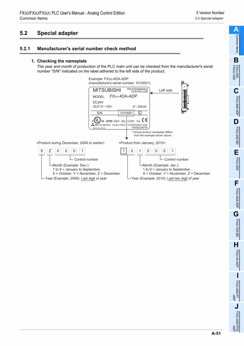
5 Version Number5.2 Special adapter
FX3G/FX3U/FX3UC PLC User's Manual - Analog Control EditionCommon Items
A
Comm
on Items
B
FX3U-4ADFX3UC-4AD
C
FX3U-4AD-ADP
D
FX3G-2AD-BD
E
FX3U-4DA
F
FX3U-4DA-ADP
G
FX3G-1DA-BD
H
FX3U-3A-ADP
I
FX3U-4AD-PT -ADP
J
FX3U-4AD-PTW -AD
5.2 Special adapter
5.2.1 Manufacturer's serial number check method
1. Checking the nameplateThe year and month of production of the PLC main unit can be checked from the manufacturer's serial number "S/N" indicated on the label adhered to the left side of the product.
Example: FX3U-4DA-ADP
(manufacture's serial number: 1010001)
1010001S/N
Left side
Year (Example: 2009): Last digit of year Year (Example: 2010): Last two digit of year
01 1 0 0 0
Control number
<Product from January, 2010><Product during December, 2009 or earlier>
1
Month (Example: Jan.):
1 to 9 = January to September,
X = October, Y = November, Z = December
9 Z 0 0 0
Control number
1
Month (Example: Dec.):
1 to 9 = January to September,
X = October, Y = November, Z = December
Actual product nameplate differs
from the example shown above.*
A-51
P

6 Manual Introduction (Types, Contents, and Obtainment)6.1 How to Use the Manuals
FX3G/FX3U/FX3UC PLC User's Manual - Analog Control EditionCommon Items 6.1 How to Use the Manuals
6. Manual Introduction (Types, Contents, and Obtainment)
This chapter describes the FX3U/FX3UC/FX3G Series PLC main unit instruction manual and the variousmanuals of analog products.
6.1 How to Use the Manuals
Various analog products can be connected to the FX Series PLC to control the analog inputs and outputs.
Analog control
For use of each analog control product:
•User's Manual - Analog Control Edition
For each analog product, use this manual for details on wiring/setup details, exampleprograms, and troubleshooting methods.
Supplied separately
PLC
For PLC wiring and installation:
•HARDWARE MANUAL (This manual is supplied with the product.)
•User's Manual - Hardware Edition
For sequence programs:
•Programming manual
Supplied
Analog products
For installation and parts identification:
•Installation Manual (For a detailed description of the programming method, refer to the separate manual.)
Thismanual
Voltage input Current input Voltage output Current output Temperature input
Depending on the product type, the "Installation Manual" or the "User's Manual" is supplied with theproduct.For a detailed description, refer to the separate manual "User's Manual - Analog Control Edition" asdescribed below:
For installation, parts identification, use, and examples of programs:
•User's Manual (Necessary information is in the user's manual, but for a detailed description, refer to the separate manual.)
Supplied separately
Supplied separately
Supplied
Supplied
A-52

6 Manual Introduction (Types, Contents, and Obtainment)6.2 Description of Related Manuals
FX3G/FX3U/FX3UC PLC User's Manual - Analog Control EditionCommon Items
A
Comm
on Items
B
FX3U-4ADFX3UC-4AD
C
FX3U-4AD-ADP
D
FX3G-2AD-BD
E
FX3U-4DA
F
FX3U-4DA-ADP
G
FX3G-1DA-BD
H
FX3U-3A-ADP
I
FX3U-4AD-PT -ADP
J
FX3U-4AD-PTW -AD
6.2 Description of Related Manuals
The main manuals necessary for the use of analog products are described below.These manuals are classified into two groups: manuals necessary for the PLC main unit, and manualsnecessary for analog products.The manuals specified as "supplied separately" are not supplied with the products. Other manuals aresupplied with the corresponding products.
6.2.1 Analog control manuals
The following manuals are common manuals that can be used for any of the FX3U/FX3UC/FX3G Series analogproducts.
6.2.2 Manuals related to the FX3G/FX3U/FX3UC Series PLC main unit
For a detailed description of the commands to be used for the sequence programs, refer to the programmingmanual. For a detailed description of the hardware, such as wiring of the PLC main unit, refer to the User'sManual - Hardware Edition.
Manual type Document number
Supplied with product or supplied
separately
Description
FX3G/FX3U/FX3UC Series PLC
FX3G/FX3U/FX3UC Series User’s Manual - Analog Control Edition
JY997D16701Supplied separately(This manual)
This manual describes the details of the FX3G/ FX3U/FX3UC Series PLC analog products.
Manual type Document number
Supplied with product or supplied
separately
Description
FX3G Series PLC
FX3G Series HARDWARE MANUAL JY997D33401 Supplied with
product
This manual describes various items necessary for the hardware of the FX3G Series PLC main unit, such as specifications, wiring, and installation.
FX3G Series User’s Manual- Hardware Edition JY997D31301 Supplied
separately
This manual describes various items necessary for the FX3G Series PLC main unit and various items for the hardware, such as extension specifications, wiring, and installation.
FX3U Series PLC
FX3U Series HARDWARE MANUAL JY997D18801 Supplied with
product
This manual describes various items necessary for the hardware of the FX3U Series PLC main unit, such as specifications, wiring, and installation.
FX3U Series User’s Manual- Hardware Edition JY997D16501 Supplied
separately
This manual describes various items necessary for the FX3U Series PLC main unit and various items for the hardware, such as extension specifications, wiring, and installation.
FX3UC Series PLC
FX3UC (D, DS, DSS) Series HARDWARE MANUAL JY997D28601 Supplied with
product
The input/output specifications and the wiring and installation methods for the FX3UC (D, DS, DSS) PLC are excerpted from the FX3UC Series User's Manual (for Hardware).For details, refer to the FX3UC Series User's Manual (for Hardware).
FX3UC-32MT-LT-2HARDWARE MANUAL JY997D31601 Supplied with
product
This manual describes various items necessary for the hardware of the FX3UC-32MT-LT-2 PLC main unit, such as specifications, wiring, and installation.
A-53
P

6 Manual Introduction (Types, Contents, and Obtainment)6.2 Description of Related Manuals
FX3G/FX3U/FX3UC PLC User's Manual - Analog Control EditionCommon Items 6.2 Description of Related Manuals
FX3UC Series User’s Manual- Hardware Edition JY997D28701 Supplied
separately
Provides detailed information on the hardware, such as the input/output specifications and detailed wiring, installation, and maintenance methods for the FX3UC PLC.
FX3G, FX3U, FX3UC Series PLC
FX3G/FX3U/FX3UC Series Programming Manual - Basic & Applied Instruction Edition
JY997D16601 Supplied separately
This manual describes the basic and application commands necessary for the FX3G/FX3U/FX3UC Series PLC.
MELSEC-Q/L/FStructured ProgrammingManual (Fundamentals)
SH-080782 Supplied separately
Programming methods, specifications, functions, etc.required to create structured programs.
FXCPU StructuredProgramming Manual(Device & Common)
JY997D26001 Supplied separately
Devices, parameters, etc. provided in structured projects of GX Works2.
FXCPU StructuredProgramming Manual(Basic & Applied Instruction)
JY997D34701 Supplied separately
Sequence instructions provided in structured projects of GX Works2.
FXCPU StructuredProgramming Manual(Application Functions)
JY997D34801 Supplied separately
Application functions provided in structured projects of GX Works2.
Manual type Document number
Supplied with product or supplied
separately
Description
A-54

6 Manual Introduction (Types, Contents, and Obtainment)6.2 Description of Related Manuals
FX3G/FX3U/FX3UC PLC User's Manual - Analog Control EditionCommon Items
A
Comm
on Items
B
FX3U-4ADFX3UC-4AD
C
FX3U-4AD-ADP
D
FX3G-2AD-BD
E
FX3U-4DA
F
FX3U-4DA-ADP
G
FX3G-1DA-BD
H
FX3U-3A-ADP
I
FX3U-4AD-PT -ADP
J
FX3U-4AD-PTW -AD
6.2.3 Manuals of analog units
The manuals of various analog units are described below:
Manual type Document number
Supplied with product or supplied
separately
Description
Analog input unit
FX3G-2AD-BDINSTALLATION MANUAL JY997D33501 Supplied with
product
This manual describes the FX3G-2AD-BD analog input expansion board hardware, such as specifications and installation.
FX3U-4ADINSTALLATION MANUAL JY997D20701 Supplied with
product
This manual describes the FX3U-4AD analog input special function block hardware, such as specifications and installation, and also describes various programs.
FX3U-4AD-ADPUSER’S MANUAL JY997D13901 Supplied with
product
This manual describes the FX3U-4AD-ADP analog input special adapter hardware, such as specifications and installation.
FX2NC-4ADUSER’S MANUAL JY997D07801 Supplied with
product
This manual describes the FX2NC-4AD analog input special function block hardware, such as specifications and installation, and also describes various programs.
FX2N-8ADUSER’S MANUAL JY992D86001 Supplied with
product
This manual describes the FX2N-8AD analog input special function block hardware, such as specifications and installation, and also describes various programs.
FX2N-4ADUSER’S GUIDE JY992D65201 Supplied with
product
This manual describes the FX2N-4AD analog input special function block hardware, such as specifications and installation, and also describes various programs.
FX2N-2ADUSER’S GUIDE JY992D74701 Supplied with
product
This manual describes the FX2N-2AD analog input special function block hardware, such as specifications and installation, and also describes various programs.
Analog output unit
FX3G-1DA-BDINSTALLATION MANUAL JY997D33601 Supplied with
product
This manual describes the FX3G-1DA-BD analog output expansion board hardware, such as specifications and installation.
FX3U-4DAINSTALLATION MANUAL JY997D20801 Supplied with
product
This manual describes the FX3U-4DA analog output special function block hardware, such as specifications and installation.
FX3U-4DA-ADPUSER’S MANUAL JY997D14001 Supplied with
product
This manual describes the FX3U-4DA-ADP analog output special adapter hardware, such as specifications and installation.
FX2NC-4DAUSER’S MANUAL JY997D07601 Supplied with
product
This manual describes the FX2NC-4DA analog output special function block hardware, such as specifications and installation, and also describes various programs.
FX2N-4DAUSER’S GUIDE JY992D65901 Supplied with
product
This manual describes the FX2N-4DA analog output special function block hardware, such as specifications and installation, and also describes various programs.
FX2N-2DAUSER’S GUIDE JY992D74901 Supplied with
product
This manual describes the FX2N-2DA analog output special function block hardware, such as specifications and installation, and also describes various programs.
Analog input/output unit
FX3U-3A-ADPUSER’S MANUAL JY997D35601 Supplied with
product
This manual describes the FX3U-3A-ADP analog input/output special adapter hardware, such as specifications and installation.
FX2N-5AUSER’S MANUAL JY997D11401 Supplied with
product
This manual describes the FX2N-5A analog input/output special function block hardware, such as specifications and installation, and also describes various programs.
FX0N-3AUSER’S GUIDE JY992D49001 Supplied with
product
This manual describes the FX0N-3A analog input/output special function block hardware, such as specifications and installation, and also describes various programs.
A-55
P

6 Manual Introduction (Types, Contents, and Obtainment)6.2 Description of Related Manuals
FX3G/FX3U/FX3UC PLC User's Manual - Analog Control EditionCommon Items 6.2 Description of Related Manuals
Manual type Document number
Supplied with product or supplied
separately
Description
Temperature sensor unit
FX3U-4AD-PT-ADPUSER’S MANUAL JY997D14701 Supplied with
product
This manual describes the FX3U-4AD-PT-ADP platinum resistance thermometer input special adapter hardware, such as specifications and installation.
FX3U-4AD-PTW-ADPUSER’S MANUAL JY997D29101 Supplied with
product
This manual describes the FX3U-4AD-PTW-ADP platinum resistance thermometer input special adapter hardware, such as specifications and installation.
FX3U-4AD-PNK-ADPUSER’S MANUAL JY997D29201 Supplied with
product
This manual describes the FX3U-4AD-PNK-ADP resistance thermometer input special adapter hardware, such as specifications and installation.
FX3U-4AD-TC-ADPUSER’S MANUAL JY997D14801 Supplied with
product
This manual describes the FX3U-4AD-TC-ADP thermocouple input special adapter hardware, such as specifications and installation.
FX2N-4AD-PTUSER’S GUIDE JY992D65601 Supplied with
product
This manual describes the FX2N-4AD-PT platinum resistance thermometer input special function block hardware, such as specifications and installation, and also describes various programs.
FX2N-4AD-TCUSER’S GUIDE JY992D65501 Supplied with
product
This manual describes the FX2N-4AD-TC thermocouple input special function block hardware, such as specifications and installation, and also describes various programs.
FX3U-4LCINSTALLATION MANUAL JY997D38901 Supplied with
product
This manual describes the FX3U-4LC temperature adjustment special function block hardware, such as specifications and installation.
FX3U-4LCUSER’S MANUAL JY997D39101 Supplied
separately
This manual describes the FX3U-4LC temperature adjustment special function block hardware, such as specifications and installation, and also describes various programs.
FX2N-2LCUSER’S GUIDE JY992D85601 Supplied with
product
This manual describes the FX2N-2LC temperature adjustment special function block hardware, such as specifications and installation.
FX2N-2LCUSER’S MANUAL JY992D85801 Supplied
separately
This manual describes the FX2N-2LC temperature adjustment special function block hardware, such as specifications and installation, and also describes various programs.
A-56

7 Generic Names and Abbreviations in This Manual6.2 Description of Related Manuals
FX3G/FX3U/FX3UC PLC User's Manual - Analog Control EditionCommon Items
A
Comm
on Items
B
FX3U-4ADFX3UC-4AD
C
FX3U-4AD-ADP
D
FX3G-2AD-BD
E
FX3U-4DA
F
FX3U-4DA-ADP
G
FX3G-1DA-BD
H
FX3U-3A-ADP
I
FX3U-4AD-PT -ADP
J
FX3U-4AD-PTW -AD
7. Generic Names and Abbreviations in This Manual
1. Main unit
2. Expansion board and special adapter
Abbreviation, generic name DescriptionPLC
FX Series PLC Generic name for the FX0, FX0S, FX1S, FX0N, FX1N, FX1, FX2(FX), FX2N, FX3G, FX3U, FX1NC, FX2NC, and FX3UC Series PLC
FX3G Series Generic name for the FX3G Series PLCFX3G Series PLC or main unit Generic name for the FX3G Series PLC main unit
FX3U Series Generic name for the FX3U Series PLCFX3U Series PLC or main unit Generic name for the FX3U Series PLC main unit
FX3UC Series Generic name for the FX3UC Series PLCFX3UC Series PLC or main unit Generic name for the FX3UC Series PLC main unit
Abbreviation, generic name DescriptionExpansion board
Expansion board
Generic name for analog expansion board, communication expansion board, special adapter connection expansion board and variable analogpotentiometer expansion board.The number of connectable units, however, depends on the type of the main unit. To check the number of connectable units, refer to the User’s Manual - Hardware Edition of the main unit to be used for your system.
Analog expansion board Generic name for 2AD-BD, 1DA-BD2AD-BD FX3G-2AD-BD1DA-BD FX3G-1DA-BD
Communication expansion board Generic name for 232BD, 422BD, 485BD, and USBBD.232BD FX3U-232-BD, FX3G-232-BD, FX2N-232-BD, FX1N-232-BD422BD FX3U-422-BD, FX3G-422-BD, FX2N-422-BD, FX1N-422-BD485BD FX3U-485-BD, FX3G-485-BD, FX2N-485-BD, FX1N-485-BDUSBBD FX3U-USB-BD
Variable analog potentiometer expansion board Generic name for 8AV-BD
8AV-BD FX3U-8AV-BD, FX3G-8AV-BDSpecial adapter connection boardor connector conversion board Generic name for CNVBD.
CNVBD FX3U-CNV-BD, FX2N-CNV-BD, FX1N-CNV-BDSpecial adapter
Special adapter
Generic name for high-speed input special adapter, high-speed output special adapter, communication special adapter, CF card special adapter, and analog special adapter.The number of connectable units, however, depends on the type of the main unit. To check the number of connectable units, refer to the User’s Manual - Hardware Edition of the main unit to be used for your system.
High-speed input/output special adapter
Generic name for high-speed input special adapter and high-speed output special adapter.
2HSY-ADP FX3U-2HSY-ADP4HSX-ADP FX3U-4HSX-ADP
Communication special adapter Generic name for communication special adapter.232ADP FX3U-232ADP(-MB), FX2NC-232ADP, FX0N-232ADP, FX-232ADP485ADP FX3U-485ADP(-MB), FX2NC-485ADP, FX0N-485ADP, FX-485ADP
A-57
P

7 Generic Names and Abbreviations in This Manual6.2 Description of Related Manuals
FX3G/FX3U/FX3UC PLC User's Manual - Analog Control EditionCommon Items 6.2 Description of Related Manuals
3. Extension unit
CF card special adapter Generic name for CF card special adapter.CF-ADP FX3U-CF-ADP
Analog special adapter Generic name for analog special adapter.4AD-ADP FX3U-4AD-ADP4DA-ADP FX3U-4DA-ADP3A-ADP FX3U-3A-ADPPT-ADP FX3U-4AD-PT-ADPPTW-ADP FX3U-4AD-PTW-ADPPNK-ADP FX3U-4AD-PNK-ADPTC-ADP FX3U-4AD-TC-ADP
Special adapter connection conversion adapter or connection conversion adapter
Generic name for CNVADP
CNVADP FX3G-CNV-ADP
Abbreviation, generic name DescriptionVoltage/current input
Extension unit
Generic name for the FX3U Series extension unit, FX3UC Series extension unit, FX2N Series extension unit, FX2NC Series extension unit, and FX0N Series extension unit.The number of connectable units, however, depends on the type of the main unit. To check the number of connectable units, refer to the User’s Manual - Hardware Edition of the main unit to be used for your system.
FX3U Series extension unit Generic name for FX3U Series special function block.FX3UC Series extension unit Generic name for FX3UC Series special function block.
FX2N Series extension unitGeneric name for FX2N Series input/output powered extension unit, FX2N Series input/output extension block, FX2N Series special function unit, and FX2N Series special function block.
FX2NC Series extension unit Generic name for FX2NC Series input/output extension block and FX2NC Series special function block.
FX0N Series extension unit Generic name for FX0N Series input/output extension block and FX0N Series special function block.
Special function unit/block
Generic name for FX3U Series special function block, FX3UC Series special function block, FX2N Series special function unit, FX2N Series special function block, FX2NC Series special function block, and FX0N Series special function block.
FX3U Series specialfunction block FX3U-4AD, FX3U-4DA, FX3U-4LC, FX3U-2HC, FX3U-20SSC-H, FX3U-64CCL
FX3UC Series specialfunction block FX3UC-4AD
FX2N Series specialfunction unit FX2N-10GM, FX2N-20GM, FX2N-1RM-E-SET, FX2N-1RM-SET
FX2N Series specialfunction block
FX2N-232IF, FX2N-16CCL-M, FX2N-32CCL, FX2N-32ASI-M, FX2N-2AD, FX2N-4AD, FX2N-8AD, FX2N-4AD-PT, FX2N-4AD-TC, FX2N-2LC, FX2N-2DA, FX2N-4DA, FX2N-5A, FX2N-1HC, FX2N-1PG-E, FX2N-1PG, FX2N-10PGThe number of connectable units, however, depends on the type of main unit. To check the number of connectable units, refer to the User’s Manual - Hardware Edition of the main unit to be used for your system.
FX2NC Series specialfunction block FX2NC-4AD, FX2NC-4DA, FX2NC-1HC
FX0N Series specialfunction block FX0N-3A
Abbreviation, generic name Description
A-58

7 Generic Names and Abbreviations in This Manual6.2 Description of Related Manuals
FX3G/FX3U/FX3UC PLC User's Manual - Analog Control EditionCommon Items
A
Comm
on Items
B
FX3U-4ADFX3UC-4AD
C
FX3U-4AD-ADP
D
FX3G-2AD-BD
E
FX3U-4DA
F
FX3U-4DA-ADP
G
FX3G-1DA-BD
H
FX3U-3A-ADP
I
FX3U-4AD-PT -ADP
J
FX3U-4AD-PTW -AD
4. Peripheral unit
5. Manual
Abbreviation, generic name DescriptionPeripheral unit
Peripheral unit Generic name for programming software, handy programming panel,and display units.
Programming toolProgramming tool Generic name for programming software, and handy programming panel.Programming software Generic name for Programming software.
GX Works2 Generic name for SW DNC-GXW2-J and SW DNC-GXW2-E programming software packages.
GX Developer Generic name for SW D5C-GPPW-J and SW D5C-GPPW-E programming software packages.
Handy programming panels(HPP)
Generic name for the following modelsFX-30P, FX-20P(-E)-SET0, FX-20P(-E), FX-10P-SET0, FX-10P(-E)
Abbreviation, generic name DescriptionFX3G hardware manual FX3G Series User's Manual - Hardware EditionFX3U hardware manual FX3U Series User's Manual - Hardware EditionFX3UC hardware manual FX3UC Series User's Manual - Hardware Edition
Programming manual FX3G/FX3U/FX3UC Series Programming Manual - Basic and Applied Instruction Edition
A-59
P

7 Generic Names and Abbreviations in This Manual6.2 Description of Related Manuals
FX3G/FX3U/FX3UC PLC User's Manual - Analog Control EditionCommon Items 6.2 Description of Related Manuals
MEMO
A-60

A
Comm
on Items
B
FX3U-4ADFX3UC-4AD
C
FX3U-4AD-ADP
D
FX3G-2AD-BD
E
FX3U-4DA
F
FX3U-4DA-ADP
G
FX3G-1DA-BD
H
FX3U-3A-ADP
I
FX3U-4AD-PT -ADP
J
FX3U-4AD-PTW -ADP
FX3G/FX3U/FX3UC PLC User's Manual - Analog Control EditionFX3U-4AD/FX3UC-4AD (4-channel Analog Input)
FX3G/FX3U/FX3UC Series Programmable Controllers
User's Manual [Analog Control Edition] FX3U-4AD (4-channel Analog Input)FX3UC-4AD (4-channel Analog Input)
Foreword
This manual describes the specifications, wiring, and operation methods for the FX3U-4AD/FX3UC-4AD special extension block (4-channel analog input) and should be read and understood before attempting to install or use the unit.Store this manual in a safe place so that you can take it out and read it whenever necessary. Always forward it to the end user.
© 2005 MITSUBISHI ELECTRIC CORPORATION
This manual confers no industrial property rights or any rights of any other kind, nor does it confer any patentlicenses. Mitsubishi Electric Corporation cannot be held responsible for any problems involving industrial propertyrights which may occur as a result of using the contents noted in this manual.
B-1

FX3G/FX3U/FX3UC PLC User's Manual - Analog Control EditionFX3U-4AD/FX3UC-4AD (4-channel Analog Input)
B-2

1 Outline1.1 Outline of Functions
A
Comm
on Items
B
FX3U-4ADFX3UC-4AD
C
FX3U-4AD-ADP
D
FX3G-2AD-BD
E
FX3U-4DA
F
FX3U-4DA-ADP
G
FX3G-1DA-BD
H
FX3U-3A-ADP
I
FX3U-4AD-PT -ADP
J
FX3U-4AD-PTW -ADP
FX3G/FX3U/FX3UC PLC User's Manual - Analog Control EditionFX3U-4AD/FX3UC-4AD (4-channel Analog Input)
1. Outline
This chapter outlines the FX3U-4AD/FX3UC-4AD.For common descriptions of the FX3U-4AD and FX3UC-4AD, these model names are referred to as the 4AD.
1.1 Outline of Functions
The FX3U-4AD is an analog special function block which is connectable with the FX3G, FX3U and FX3UCSeries PLC used to capture 4-ch voltage/current data. The FX3UC-4AD cannot be connected to the FX3G/FX3U Series PLC.
1) Up to 8*1 units can be connected to the FX3G/FX3U/FX3UC Series PLC.(including the other special function blocks).
2) Either "voltage input" or "current input" can be specified for each channel.3) The A/D conversion values will be stored in the 4AD buffer memory (BFM).4) Set the digital filter to read out stable A/D conversion values.5) For each channel, up to 1,700 A/D conversion values can be stored as history data.
*1. Up to 7 units can be connected to the FX3UC-32MT-LT(-2) PLC.*2. This function is only available for FX3U and FX3UC PLCs.
FX3UC Series PLC
Number of connectable units
• • • • • •For a detailed description ofwiring, refer to Chapter 3.
• • • • • •
To check the connectable PLCmodel number, refer toSection 1.3.
Point and section to bereferred to
System
• • • • • •
• • • • • • • • •
Buffer memory
BFM#0
BFM#6999
• • • • • •
For a detailed description ofanalog data reading programs,refer to Chapter 4, 6, and 7.
For a detailed description ofthe buffer memory, refer toSection 5.3, and Section 5.4.
To use FROM/TO instructionor to directly specify the BFM,refer to Section 5.2.
Flowmeter, pressure sensor, etc.
Analog data
Refer to the system configuration shown in the FX3G/FX3U/FX3UC User's Manual - Hardware Edition to check thenumber of connectable units and to configure the entire system.
Transmission directionProgram
• FROM(FNC 78) • TO(FNC 79)
• BFM direct specification(U\G)*2
Up to 8 units*1 connect to the FX3G/FX3U/FX3UC Series PLC(including other types of special function blocks)
• •
•
• • • • • •
• • • • • •
FX3G/FX3U Series PLC
B-3

1 Outline1.2 Setup Procedure Before Starting Operation
FX3G/FX3U/FX3UC PLC User's Manual - Analog Control EditionFX3U-4AD/FX3UC-4AD (4-channel Analog Input)
1.2 Setup Procedure Before Starting Operation
Before starting to use the 4AD, follow the procedure below to set up the system:
Specifications:• Operation environment• Performance specifications• Input characteristics
Check of specifications
Refer to Chapter 2.
System configuration and selection
Wiring
Refer to Chapter 3.
FX3U-4AD/FX3UC-4AD
Refer to the common pages.
Wiring:• Power supply line• Analog input line
Outline of system:• Version number of compatible PLC• Version number of compatible programming tool
Outline
Refer to Chapter 1.
System configuration:(Refer to the analog control commonpages.)• Selection of units
Program edit:• Basic program• Convenient function program
If the error status data or the input analog value isabnormal, refer to Chapter 8 "Troubleshooting."
Program edit
Adjustment of input characteristics
Refer to Chapter 6.
Adjustment of input characteristics:• Input characteristics change procedure
Buffer memory (BFM) check
Refer to Chapter 5.
Buffer memory:• Buffer memory read/write method• List of buffer memories• Details of buffer memory
Refer to Chapter 7.
Analog data reading (test program)
Refer to Chapter 4.
Input mode specification:• Input mode specification program for channel 1 to 4
B-4

1 Outline1.3 Connectable PLC and Version Numbers
A
Comm
on Items
B
FX3U-4ADFX3UC-4AD
C
FX3U-4AD-ADP
D
FX3G-2AD-BD
E
FX3U-4DA
F
FX3U-4DA-ADP
G
FX3G-1DA-BD
H
FX3U-3A-ADP
I
FX3U-4AD-PT -ADP
J
FX3U-4AD-PTW -ADP
FX3G/FX3U/FX3UC PLC User's Manual - Analog Control EditionFX3U-4AD/FX3UC-4AD (4-channel Analog Input)
1.3 Connectable PLC and Version Numbers
FX3U-4AD is compatible with the following PLC.
FX3UC-4AD is compatible with the following PLC.
1. Version checkSpecial data register D8001 contains information for determining the PLC version number.
→ For a detailed description of the version check, refer to A. Common Items Subsection 5.1.2.
2. How to check the manufacturer's serial numberThe year and month of production of the product can be checked on the nameplate, and on the front of theproduct.
→ For a detailed description of how to check the manufacturer's serial number,refer to A. Common Items Subsection 5.1.1.
1.4 Compatible Programming Tool Version Number
Use a programming tool with the following version number to create 4AD programs for the FX3G/FX3U/FX3UCSeries PLC.
1. GX Works2
2. GX Developer• FX3U/FX3UC Series PLC
• FX3G Series PLC
If a programming tool with the wrong version number is used, some instructions and devices cannot be used.*1. For Ver. 8.13P to 8.24A of GX Developer, select FX3UC for the PLC type.
3. FX-30P
Compatible PLC Version number Date of productionFX3U Series PLC Ver. 2.20 or later from first product
FX3UC Series PLC Ver. 1.30 or later August 2004 and later
FX3G Series PLC Ver. 1.00 or later from first product
Compatible PLC Version number Date of productionFX3UC Series PLC Ver. 1.30 or later August 2004 and later
Software Version number RemarksGX Works2SW DNC-GXW2-J Ver. 1.07H or later -
GX Works2SW DNC-GXW2-E Ver. 1.08J or later -
Software Version number RemarksGX DeveloperSW D5C-GPPW-J Ver. 8.13P or later
When selecting the model, select FX3U(C)*1.GX DeveloperSW D5C-GPPW-E Ver. 8.18U or later
Software Version number RemarksGX Developer• SW D5C-GPPW-J• SW D5C-GPPW-E
Ver. 8.72A or later -
Model name Version number RemarksFX-30P Ver.1.00 or later -
B-5

2 Specifications2.1 Generic Specifications
FX3G/FX3U/FX3UC PLC User's Manual - Analog Control EditionFX3U-4AD/FX3UC-4AD (4-channel Analog Input)
2. Specifications
This chapter describes the general, power supply, and performance specifications for the 4AD.
2.1 Generic Specifications
*1. The criterion is shown in IEC61131-2.*2. The direct mounting method cannot be used with FX3UC-4AD.
When this block is connected to the FX3UC Series PLC, the direct mounting method cannot be used.*3.
→ For a detailed description of grounding, refer to Section 3.5.*4. If the pressure is higher than the atmospheric pressure, do not use the 4AD; 4AD may malfunction.
Item SpecificationsAmbient temperature
0 to 55°C (32 to 131°F) when operating-25 to 75°C (-13 to 167°F) when stored
Relative humidity 5 to 95%RH (no condensation) when operating
Vibration resistance*1
Frequency(Hz)
Acceleration(m/s2)
Half amplitude(mm)
10 times of testing in each direction (X-, Y-, and Z-axis directions) (Total: 80 min, each)
DIN Rail Mounting10 - 57 - 0.035
57 - 150 4.9 -
Direct Mounting*210 - 57 - 0.075
57 - 150 9.8 -
Shock resistance*1 147 m/s2 Acceleration, Action time: 11ms, 3 times by half-sine pulse in each direction X, Y, and Z
Noise resistance
Using noise simulator of:Noise voltage: 1,000Vp-p / Noise width: 1µs / Rise: 1ns / Cycle: 30 to 100Hz
Dielectric withstand voltage
500 V AC, for 1 minBetween all terminals and ground terminal
Insulation resistance
5MΩ or more using 500V DC insulation resistance meter
GroundingClass D grounding (grounding resistance: 100 Ω or less) <Common grounding with a heavy electrical system is not allowed.>*3
Workingatmosphere Free from corrosive or flammable gas and excessive conductive dust
Workingaltitude < 2000m*4
PLC OtherequipmentPLC Other
equipmentPLC Otherequipment
Shared groundingGood condition
Common groundingNot allowed
Independent groundingBest condition
B-6

2 Specifications2.2 Power Supply Specifications
A
Comm
on Items
B
FX3U-4ADFX3UC-4AD
C
FX3U-4AD-ADP
D
FX3G-2AD-BD
E
FX3U-4DA
F
FX3U-4DA-ADP
G
FX3G-1DA-BD
H
FX3U-3A-ADP
I
FX3U-4AD-PT -ADP
J
FX3U-4AD-PTW -ADP
FX3G/FX3U/FX3UC PLC User's Manual - Analog Control EditionFX3U-4AD/FX3UC-4AD (4-channel Analog Input)
2.2 Power Supply Specifications
FX3U-4AD
FX3UC-4AD
2.3 Performance Specifications
*1. Adjustment of the offset or gain value will not affect the resolution. In the direct indication mode,however, the offset/gain cannot be adjusted.
*2. The offset and the gain should satisfy the following condition:1V ≤ (Gain - Offset)
*3. The offset and the gain should satisfy the following condition:3 mA ≤ (Gain - Offset) ≤ 30 mA
*4. If 1 or more channels use the digital filter(s), the time required for A/D conversion will be "5 ms × number of selected channels."
Item SpecificationsA/D conversion circuit drive power
24V DC ±10%, 90mA(It is necessary to supply 24V DC from the terminal block.)
CPU drive power5V DC, 110mA(Since the internal power is supplied from the main unit, it is not necessary to supply powerexternally.)
Item SpecificationsA/D conversion circuit drive power
24V DC ±10%, 80mA(It is necessary to supply 24V DC from the power connector.)
CPU drive power 5V DC, 100mA(Since the internal power is supplied from the main unit, it is not necessary to supply the power.)
ItemSpecifications
Voltage input Current input
Analog input range -10V to +10V DC(Input resistance: 200kΩ)
-20mA to +20mA DC, 4mA to 20mA DC(Input resistance: 250Ω)
Offset*1 -10V to +9V*2 -20mA to +17mA*3
Gain*1 -9V to +10V*2 -17mA to +30mA*3
Absolute maximum input ±15V ±30mA
Digital output With sign, 16bits, binary With sign, 15bits, binary
Resolution*4 0.32mV (20V × 1/ 64,000)2.5mV (20V × 1/8000)
1.25µA (40mA × 1/ 32,000)5.00µA (40mA × 1/8000)
Overall accuracy
• Ambient temperature: 25°C±5°C±0.3% (±60mV) for 20V full scale
• Ambient temperature: 0°C to 55°C±0.5% (±100mV) for 20V full scale
• Ambient temperature: 25°C±5°C±0.5% (±200µA) for 40mA full scaleSame accuracy (±200µA) for 4mA to 20mA input
• Ambient temperature: 0°C to 55°C±1% (±400µA) for 40mV full scaleSame accuracy (±400µA) for 4mA to 20mA input
Time required for A/D conversion
500µs × number of selected channels(If 1 or more channels use the digital filter(s): 5ms × number of selected channels)
Insulation method• The photocoupler is used to insulate the analog input area from the PLC.• The DC/DC converter is used to insulate the analog input area from the power supply unit.• Channels are not insulated from each other.
Number of I/O points occupied 8 points (Taken from either the input or output points of the PLC.)
B-7

2 Specifications2.4 Input Mode (Characteristics) BFM #0
FX3G/FX3U/FX3UC PLC User's Manual - Analog Control EditionFX3U-4AD/FX3UC-4AD (4-channel Analog Input)
2.4 Input Mode (Characteristics) BFM #0
For the 4AD, there are two types of input characteristics: voltage (-10 to +10V) and current (4 to 20mA, -20 to+20mA) input characteristics. The input characteristics depend on the set input mode as described below. Foreach input range, there are 3 input modes.
1. Voltage input characteristics [-10 to +10V] (Input mode: 0 to 2)
2. Current input characteristics [4 to 20mA] (Input mode: 3 to 5)
Set input mode: 0Input type: Voltage inputAnalog input range: -10 to +10VDigital output range: -32000 to +32000Offset/gain adjustment: Possible
Set input mode: 1Input type: Voltage inputAnalog input range: -10 to +10VDigital output range: -4000 to +4000Offset/gain adjustment: Possible
Set input mode: 2Input type: Voltage input
(analog value direct indication)Analog input range: -10 to +10VDigital output range: -10000 to +10000Offset/gain adjustment: Impossible
Set input mode: 3Input type: Current input Analog input range: 4 to 20mADigital output range: 0 to 16000Offset/gain adjustment: Possible
Set input mode: 4Input type: Current inputAnalog input range: 4 to 20 mADigital output range: 0 to 4000Offset/gain adjustment: Possible
Set input mode: 5Input type: Current input
(analog value direct indication)Analog input range: 4 to 20 mADigital output range: 4000 to 20000Offset/gain adjustment: Impossible
Digital value
+32000+32640
-32640-32000
-10V+10V
0
+10.
2V
-10.
2V
Inputvoltage
+4000+4080
-4080-4000
-10V+10V
0
+10.
2V
-10.
2V
Digital value
Inputvoltage
+10000+10200
-10200-10000
-10V+10V
0
+10.
2V
-10.
2V
Digital value
Inputvoltage
16000
4mA0
Digital value
Currentinput
20mA
16400
20.4
mA
4000
4mA0
Digital value
Currentinput
20mA
4100
20.4
mA
20000
4mA0
Digital value
Currentinput
20mA
20400
20.4
mA
4000
B-8

2 Specifications2.4 Input Mode (Characteristics) BFM #0
A
Comm
on Items
B
FX3U-4ADFX3UC-4AD
C
FX3U-4AD-ADP
D
FX3G-2AD-BD
E
FX3U-4DA
F
FX3U-4DA-ADP
G
FX3G-1DA-BD
H
FX3U-3A-ADP
I
FX3U-4AD-PT -ADP
J
FX3U-4AD-PTW -ADP
FX3G/FX3U/FX3UC PLC User's Manual - Analog Control EditionFX3U-4AD/FX3UC-4AD (4-channel Analog Input)
3. Current input characteristics [-20 to +20mA] (Input mode: 6 to 8)
Set input mode: 6Input type: Current inputAnalog input range: -20 to +20mADigital output range: -16000 to +16000Offset/gain adjustment: Possible
Set input mode: 7Input type: Current inputAnalog input range: -20 to +20mADigital output range: -4000 to +4000Offset/gain adjustment: Possible
Set input mode: 8Input type: Current input
(analog value direct indication)Analog input range: -20 to +20mADigital output range: -20000 to +20000Offset/gain adjustment: Impossible
Digital value
+16000
-16000
-20mA+20mA
0
+16320
+20.
4mA
-16320
-20.
4mA
CurrentInput
+4000
-4000
-20mA+20mA
0
Digital value+4080
+20.
4mA
-4080-2
0.4m
A
CurrentInput
+20000
-20000
-20mA+20mA
0
Digital value+20400
+20.
4mA
-20400
-20.
4mA
CurrentInput
B-9

3 Wiring2.4 Input Mode (Characteristics) BFM #0
FX3G/FX3U/FX3UC PLC User's Manual - Analog Control EditionFX3U-4AD/FX3UC-4AD (4-channel Analog Input)
3. Wiring
This chapter describes the 4AD wiring.Observe the following cautions when wiring the 4AD.
WIRING PRECAUTIONS
• Make sure to cut off all phases of the power supply externally before attempting wiring work.Failure to do so may cause electric shock or damages to the product.
WIRING PRECAUTIONS
• Connect the DC power supply wiring to the dedicated terminals described in this manual.If an AC power supply is connected to a DC input/output terminal or DC power supply terminal, the PLC will beburnt out.
• Do not wire vacant terminals externally.Doing so may damage the product.
• Perform class D grounding (grounding resistance: 100Ω or less) to the grounding terminal on the main unit.Do not use common grounding with heavy electrical systems.
• When drilling screw holes or wiring, make sure cutting or wire debris does not enter the ventilation slits.Failure to do so may cause fire, equipment failures or malfunctions.
• Make sure to observe the following precautions in order to prevent malfunctions under the influence of noise:- Do not bundle the power line or twisted shielded cable together with or lay it close to the main circuit, high-
voltage line, or load line.Otherwise, noise disturbance and/or surge induction are likely to take place. As a guideline, lay the control line at least 100mm (3.94") or more away from the main circuit, high-voltage line, or load line.
- Ground the shield of the analog input/output cable at one point on the signal receiving side. However, do not use common grounding with heavy electrical systems.
• Make sure to properly wire to the European terminal board in accordance with the following precautions.Failure to do so may cause electric shock, equipment failures, a short-circuit, wire breakage, malfunctions, ordamage to the product.- The disposal size of the cable end should follow the dimensions described in the manual.- Tightening torque should follow the specifications in the manual.- Twist the end of strand wire and make sure there are no loose wires. - Do not solder-plate the electric wire ends.- Do not connect more than the specified number of wires or electric wires of unspecified size.- Affix the electric wires so that neither the terminal block nor the connected parts are directly stressed.
• Make sure to properly wire the terminal block in accordance with the following precautions.Failure to do so may cause electric shock, equipment failures, a short-circuit, wire breakage, malfunctions, ordamage to the product.- The disposal size of the cable end should follow the dimensions described in the manual.- Tightening torque should follow the specifications in the manual.
B-10

3 Wiring3.1 Terminal Layout
A
Comm
on Items
B
FX3U-4ADFX3UC-4AD
C
FX3U-4AD-ADP
D
FX3G-2AD-BD
E
FX3U-4DA
F
FX3U-4DA-ADP
G
FX3G-1DA-BD
H
FX3U-3A-ADP
I
FX3U-4AD-PT -ADP
J
FX3U-4AD-PTW -ADP
FX3G/FX3U/FX3UC PLC User's Manual - Analog Control EditionFX3U-4AD/FX3UC-4AD (4-channel Analog Input)
3.1 Terminal Layout
FX3U-4AD
FX3UC-4AD
24+24-
VI-I+FG
FGV+VI-
FGV+VI-
V+
V+VI-I+
I+
I+
Signal Application
Ground terminal
24V DC power supply
Channel-1 analog input
Channel-2 analog input
Channel-4 analog input
Channel-3 analog input
FX3UC-4AD
V3+
I3+
CO
M3
SLD
V4+
I4+
CO
M4
SLD
V1+
I1+
CO
M1
SLD
V2+
I2+
CO
M2
SLD
PW
24V
A/D
••
Signal Application
Ground terminal
Channel-1 analog input
Channel-2 analog input
Channel-3 analog input
Channel-4 analog input
Do not connect any lines.
V1+I1+
COM1
V2+I2+
COM2
V3+I3+
COM3
V4+I4+
COM4
SLD
SLD••
SLD
SLD
B-11

3 Wiring3.2 Cable and Terminal Tightening Torque
FX3G/FX3U/FX3UC PLC User's Manual - Analog Control EditionFX3U-4AD/FX3UC-4AD (4-channel Analog Input)
3.2 Cable and Terminal Tightening Torque
3.2.1 Power cable (FX3UC-4AD)
The power crossover cable (type "C" shown in the following table) is supplied with the FX3UC-4AD.To connect the power cable, refer to the User's Manual - Hardware Edition of the PLC main unit.There are 3 types of power cables as shown in the following table. Types "A" and "B" are supplied with the main unit, and type "C" is supplied with the input extension blocks or the special function blocks for FX3UC Series.
The crossover cable (type "C") can skip up to 4 16-point output blocks to connect units.If more blocks should be skipped to supply power to an input block, use cable type "B".
<Self-made power cable>To use self-made power cables, use the following wire rods and connectors:
Supply the 24V DC power to FX3UC-4AD via the power supply connector.
3.2.2 Cable (FX3U-4AD)
The FX3U-4AD terminal block is designed for M3 screws.The end disposal of the cable shows blow.Tighten the terminal to a torque of 0.5 to 0.8 N•m.Do not tighten terminal screws with a torque exceeding the regulation torque.Failure to do so may cause equipment failures or malfunctions.• When one wire is connected to one terminal
• When two wires are connected to one terminal
Type Application Model Length Cable supplied with
A Power cable for main unit FX2NC-100MPCB 1m(3’ 3")
FX3UC Series PLC main unitB Input power cable for input
extension block FX2NC-100BPCB 1m(3’ 3")
C Input power crossover cable for input extension block FX2NC-10BPCB1 0.1m
(0’ 3")• Input extension block for FX2NC Series• Special function block for FX3UC/FX2NC Series
Specifications/model
Wire size AWG24 (0.2mm2)Crimp-style terminal 1602-0069 (manufactured by Molex Japan Co., Ltd.)
HousingFor main unit 51030-0330 (manufactured by Molex Japan Co., Ltd.)For input extension block 51030-0230 (manufactured by Molex Japan Co., Ltd.)
TerminalTerminal
Terminalscrew
Crimpterminal
6.2mm(0.24")
or less
3.2(0.13")
6.2mm(0.24")
or less
3.2(0.13")
Terminalscrew
Crimpterminal
Terminal
6.2mm(0.24")
or less
3.2(0.13")
6.3mm(0.25")
or more
6.2mm(0.24")
or less
3.2(0.13")
6.3mm(0.25")
or more
B-12

3 Wiring3.2 Cable and Terminal Tightening Torque
A
Comm
on Items
B
FX3U-4ADFX3UC-4AD
C
FX3U-4AD-ADP
D
FX3G-2AD-BD
E
FX3U-4DA
F
FX3U-4DA-ADP
G
FX3G-1DA-BD
H
FX3U-3A-ADP
I
FX3U-4AD-PT -ADP
J
FX3U-4AD-PTW -ADP
FX3G/FX3U/FX3UC PLC User's Manual - Analog Control EditionFX3U-4AD/FX3UC-4AD (4-channel Analog Input)
3.2.3 Cable (FX3UC-4AD)
Use the following cables to connect with counterpart equipment. Terminate the cable end as shown below.
1. CableApplicable cable and tightening torque
*1. Old model name : CRIMPFOX ZA 3*2. Old model name : CRIMPFOX UD 6
2. Termination of cable endTo terminate the cable, treat the stranded/single-wire directly or use the rod terminal with insulation sleeve.• To directly terminate end of stranded/single-wire cable:
- Terminate the end of the stranded cable so that the "barbed wires" cannot protrude.
- Do not solder-plate the end of the cable.• To terminate cable end using rod terminal with insulation sleeve:
If the cable sheath is too thick, it may be difficult to insert the cableinto the insulation sleeve. For this reason, select an appropriate cablewhile referring to the external view.
<Reference>
*3. Old model name : CRIMPFOX ZA 3*4. Old model name : CRIMPFOX UD 6
3. Tool• To tighten terminals, use a purchased small-sized screwdriver whose head is straight and is not widened
as shown in the right figure.
Note:If the diameter of screwdriver grip is too small, tightening torque will notbe able to be achieved. To achieve the appropriate tightening torqueshown in the table above, use the following screwdriver or anappropriate replacement (grip diameter: approximately 25mm (0.98")).<Reference>
Wire size (stranded/single-wire)
Tightening torque Termination
Single wire 0.3mm2 to 0.5mm2
(AWG22 to 20)
0.22N•m to 0.25N•m
• To connect a stranded cable, peel the cover off the cableand then twist the core before connection.
• To connect a single-wire cable, peel the cover off thecable before connection.Double wire 0.3mm2(AWG22)
Rod terminal with insulation sleeve
0.3mm2 to 0.5mm2
(AWG22 to 20)(Refer to the external view of rod terminal shown in the following figure.)
• Rod terminal with insulation sleeve(recommended terminal)AI 0.5-8WH : Manufactured by Phoenix Contact
• Caulking toolCRIMPFOX 6*1 : Manufactured by Phoenix Contact(or CRIMPFOX 6T-F*2 : Manufactured by Phoenix Contact)
Manufacturer Model Caulking tool
Phoenix Contact AI 0.5-8WH CRIMPFOX 6*3
(or CRIMPFOX 6T-F*4)
Manufacturer ModelPhoenix Contact SZS 0.4×2.5
9mm
Termination of cable end
(0.35")
8mm (0.31")
Contact area(Crimp area)
14mm2.6mm(0.1")
Insulation sleeve
(0.55")
0.4mm 2.5mm
The headshould bestraight.
(0.01") (0.09")
B-13

3 Wiring3.3 Examples of Power Supply Circuit
FX3G/FX3U/FX3UC PLC User's Manual - Analog Control EditionFX3U-4AD/FX3UC-4AD (4-channel Analog Input)
3.3 Examples of Power Supply Circuit
3.3.1 FX3U-4AD
Below are shown examples of circuits for using the 24V DC service power supply of the FX3G/FX3U SeriesPLC.1) Sink input [- common] wiring
2) Source input [+ common] wiring
Class-Dgrounding
L N
FX3G/FX3U Series PLC(main unit)
24+ 24-S/S 0V 24V
+15V
-15V
FX3U-4AD
AC power100 to 240 V
Connect the "S/S" terminal of the main unit to the "24V" terminal.
Class-Dgrounding
L N
(main unit)
24+ 24-S/S 0V 24V
+15V
-15V
FX3U-4AD
AC power100 to 240 V
Connect the "S/S" terminal of the main unit to the "0V" terminal.
FX3G/FX3U Series PLC
B-14

3 Wiring3.3 Examples of Power Supply Circuit
A
Comm
on Items
B
FX3U-4ADFX3UC-4AD
C
FX3U-4AD-ADP
D
FX3G-2AD-BD
E
FX3U-4DA
F
FX3U-4DA-ADP
G
FX3G-1DA-BD
H
FX3U-3A-ADP
I
FX3U-4AD-PT -ADP
J
FX3U-4AD-PTW -ADP
FX3G/FX3U/FX3UC PLC User's Manual - Analog Control EditionFX3U-4AD/FX3UC-4AD (4-channel Analog Input)
3.3.2 FX3UC-4AD
*1. The FX3UC- MT/D and FX3UC-32MT-LT(-2) are supplied together with power cable.*2. The FX2NC- EX-DS and FX2NC-16EX-T-DS do not have a power connector, and receive power
from the input connector.
3.3.3 Cautions regarding connection of power cables
• Ground the " " terminal and " " terminal to the Class - D grounding line (100 Ω or less) together with the ground terminal of the main unit.
• To perform crossover wiring to connect the power line from FX3UC-4AD to a succeeding extension block, remove the resin cover from the power crossover connector using nippers.
• For the timing of power-on/off when using an external power supply, see the following manual of the connected PLC.
→ Refer to the FX3G Series User’s Manual - Hardware Edition.→ Refer to the FX3U Series User’s Manual - Hardware Edition.
→ Refer to the FX3UC Series User’s Manual - Hardware Edition.
24V DC
Class-Dgrounding
GreenRedBlack
FX3UC Series PLC(Main unit)
Power connector
24+24-
FX2NC-10BPCB1Power crossover cable
FX2NC-100BPCBPower cable*1
FX2NC Series PLC(Input extension block*2)
RedBlack
24+24- 24+24-
Powercrossoverconnector
Powerconnector
Terminal block
Powerconnector
+15V
24+24- 24+24-
-15V
FX3UC-4AD
Powercrossoverconnector
+15V
24+24- 24+24-
-15V
FX3UC-4AD
Black Red Black RedBlack RedBlack Red
Powerconnector
FX2NC-10BPCB1Power crossover cable
Terminal block
Powercrossoverconnector
B-15

3 Wiring3.4 Analog Input Line
FX3G/FX3U/FX3UC PLC User's Manual - Analog Control EditionFX3U-4AD/FX3UC-4AD (4-channel Analog Input)
3.4 Analog Input Line
The analog input type, "voltage input "or "current input", can be selected for each channel.
3.4.1 FX3U-4AD
*1. For FX3G/FX3U Series PLC (AC power type), the 24V DC service power supply is also available.
*2. The [FG] terminal and the [ ] terminal are connected internally. There is no “FG” terminal for ch1. When using ch1, connect directly to the [ ] terminal.
*3. Use a 2-core twisted shield wire for analog input line, and separate it from other power lines orinductive lines.
*4. For the current input, short-circuit the [V+] terminal and the [I+] terminal. *5. If there is voltage ripple in the input voltage or there is noise in the external wiring, connect a capacitor
of approximately 0.1 to 0.47µF 25 V.
ch : represents the channel number.
250Ω
6.8kΩ ch
200kΩ
FX3U-4AD
*3
24V DC+15V
If current input isselected
If voltage input isselected
*4
External power supplywiring
*1
I+
VI-
V+
FG
24+
24-
ch
ch*3
-15V
Class-D grounding *2
*2
*5 250Ω
200kΩ
I+
VI-
V+
FG*2
6.8kΩ ch
B-16

3 Wiring3.5 Grounding
A
Comm
on Items
B
FX3U-4ADFX3UC-4AD
C
FX3U-4AD-ADP
D
FX3G-2AD-BD
E
FX3U-4DA
F
FX3U-4DA-ADP
G
FX3G-1DA-BD
H
FX3U-3A-ADP
I
FX3U-4AD-PT -ADP
J
FX3U-4AD-PTW -ADP
FX3G/FX3U/FX3UC PLC User's Manual - Analog Control EditionFX3U-4AD/FX3UC-4AD (4-channel Analog Input)
3.4.2 FX3UC-4AD
*1. Use the 2-core shielded twisted pair cable for the analog input lines, and separate the analog input lines from the other motive power lines or inductive lines.
*2. To use the current input, be sure to short circuit the line between the V + terminal and the I + terminal ( : channel number).
*3. The SLD and " " terminals are connected to each other inside.
*4. Do not connect any lines to the "•" terminal.
3.5 Grounding
Grounding should be performed as stated below.• The grounding resistance should be 100Ω or less.• Independent grounding should be performed for best results.
When independent grounding is not performed, perform "shared grounding" as shown in the following figure.
→ For details, refer to the User’s Manual - Hardware Edition of each Series.
• Use the following grounding wire.
• The PLC grounding point should be close, and all grounding wires should be as short as possible.
FX3U-4AD AWG14 (2mm2)
FX3UC-4AD AWG22-20 (0.3 to 0.5mm2)
250Ω
6.8kΩ ch
200kΩ
FX3UC-4AD
V +, I +, ch : represents the channel number.
Terminalblock
I +COM
V +*1
I +COM
V + 250Ω6.8kΩ ch
200kΩ
*1
If current input isselected
If voltage input isselected
*2
•
SLD
SLD *3
*4
Class-Dgrounding
PLC OtherequipmentPLC Other
equipmentPLC Otherequipment
Shared groundingGood condition
Common groundingNot allowed
Independent groundingBest condition
B-17

4 Analog Input4.1 Analog Input Procedures
FX3G/FX3U/FX3UC PLC User's Manual - Analog Control EditionFX3U-4AD/FX3UC-4AD (4-channel Analog Input)
4. Analog Input
This chapter describes the minimum programming necessary to readout the 4AD analog data.Follow the procedure below to confirm that the analog data can be properly read out.
4.1 Analog Input Procedures
1 Unit number check
Unit numbers from 0 to 7 will be assigned to the special function units/blocks starting from the left.When units/blocks are connected to the FX3UC-32MT-LT(-2) PLC, unit numbers from 1 to 7 areassigned. Check the unit number assigned to the 4AD.
2 Input mode (BFM #0) setting
Depending on the analog signal generator to be connected, set the input mode (BFM #0) for eachchannel.
Use hexadecimal numbers for input mode setting. Set the corresponding channel digit to the inputmode setting value specified in the following table:
→ For a detailed description of the standard input characteristics, refer to Section 2.4.→ For a detailed description of the input mode (BFM #0), refer to Subsection 5.4.1.
Settingvalue Input mode Analog input
range Digital output range
0 Voltage input mode -10V to +10V -32000 to +32000
1 Voltage input mode -10V to +10V -4000 to +4000
2 Voltage inputAnalog value direct indication mode -10V to +10V -10000 to +10000
3 Current input mode 4mA to 20mA 0 to 16000
4 Current input mode 4mA to 20mA 0 to 4000
5 Current input modeAnalog value direct indication mode 4mA to 20mA 4000 to 20000
6 Current input mode -20mA to +20mA -16000 to +16000
7 Current input mode -20mA to +20mA -4000 to +4000
8 Current input modeAnalog value direct indication mode -20mA to +20mA -20000 to +20000
F Channel not used
Main unit(FX3U Series
PLC)
Input/outputextension
blockSpecial
function blockSpecial
function blockInput/outputextension
blockSpecial
function unit
Unitnumber: 0
Unitnumber: 1
Unitnumber: 2
Hch4ch3 ch2
ch1
B-18

4 Analog Input4.1 Analog Input Procedures
A
Comm
on Items
B
FX3U-4ADFX3UC-4AD
C
FX3U-4AD-ADP
D
FX3G-2AD-BD
E
FX3U-4DA
F
FX3U-4DA-ADP
G
FX3G-1DA-BD
H
FX3U-3A-ADP
I
FX3U-4AD-PT -ADP
J
FX3U-4AD-PTW -ADP
FX3G/FX3U/FX3UC PLC User's Manual - Analog Control EditionFX3U-4AD/FX3UC-4AD (4-channel Analog Input)
3 Creation of sequence programCreate the program as follows to read analog signals.• While referring to step 2, set the input mode "H****".• While referring to step 1, set the unit number in
- Program Example (For FX3U, FX3UC Series PLCs)*1
*1. Use the FROM and TO instructions in FX3G PLCs.
4 Sequence program transfer and data register check1) Transfer the sequence program, and start the PLC.2) The 4AD analog data input mode will be stored in data registers (D0 to D3) of the PLC.3) Check that the data is stored in D0 to D3.
→ If the data is not properly stored, refer to Chapter 8 "Troubleshooting."
M8002FNC 12
MOVH**** U\G0
P
M8000K50T0
T0
Specify the input mode (BFM #0) for channels1 to 4.
Initial pulse
FNC 16BMOV
U\G10 D0 K45 seconds after starting the PLC, the digitalvalues of channels 1 to 4 (BFM #10 through#13) will be read out to D0 to D3.
Input mode (step 2)
Unit number (step 1)
Unit number (step 1)
RUN monitor
B-19

5 Buffer Memory (BFM)5.1 Assignment of Unit Numbers and Outline of Buffer Memory
FX3G/FX3U/FX3UC PLC User's Manual - Analog Control EditionFX3U-4AD/FX3UC-4AD (4-channel Analog Input)
5. Buffer Memory (BFM)
This chapter describes the buffer memory incorporated in 4AD.
5.1 Assignment of Unit Numbers and Outline of Buffer Memory
1. Assignment of unit numbersUnit numbers from 0 to 7 will be assigned to the special function units/blocks starting from the left. When the units/blocks are connected to the FX3UC-32MT-LT(-2) PLC, unit numbers from 1 to 7 are assigned.
When connected to the FX3G/FX3U/FX3UC (D, DS, DSS) Series PLC
When connected to the FX3UC-32MT-LT(-2) PLC
Main unitInput/outputextension
blockSpecial
function blockSpecial
function blockInput/outputextension
blockSpecial
function unit
Unitnumber: 0
Unitnumber: 1
Unitnumber: 2
Main unit(FX3UC-32MT
-LT(-2))
Input/outputextension
block
Specialfunction block
Specialfunction block
Input/outputextension
block
Specialfunction unit
Unit number: 0(IncorporatedCC-Link/LT)
Unitnumber: 1
Unitnumber: 2
Unitnumber: 3
B-20

5 Buffer Memory (BFM)5.1 Assignment of Unit Numbers and Outline of Buffer Memory
A
Comm
on Items
B
FX3U-4ADFX3UC-4AD
C
FX3U-4AD-ADP
D
FX3G-2AD-BD
E
FX3U-4DA
F
FX3U-4DA-ADP
G
FX3G-1DA-BD
H
FX3U-3A-ADP
I
FX3U-4AD-PT -ADP
J
FX3U-4AD-PTW -ADP
FX3G/FX3U/FX3UC PLC User's Manual - Analog Control EditionFX3U-4AD/FX3UC-4AD (4-channel Analog Input)
2. Outline of buffer memoryThe analog signals input into the 4AD will be converted into digital values and then stored in the 4AD buffermemory.To switch the input mode between voltage input and current input, or to adjust the offset or gain, numeric datawill be sent from the main unit and written/set in the 4AD buffer memory.To read/write data from/to the 4AD buffer memory, the buffer memory can be directly specified using theFROM/TO instruction or an applied instruction. Using this function, sequence programs can be easily created.
→ For a detailed description of buffer memory reading/writing, refer to Section 5.2.→ For a detailed description of the buffer memory, refer to Section 5.4.
*1. Since buffer memory direct specification (U\G) can directly specify the buffer memory in the source or
destination area of an applied instruction, programs can be created efficiently. (This function is supported
only in FX3U/FX3UC PLCs.)
Main unit
Sequenceprogram
4AD
Buffermemory
A/Dconversion
4AD
Buffermemory
A/Dconversion
Analog dataAnalog data
Digitalvalue
Digitalvalue
Flowmeter, pressure sensor, etc.
• TO instruction
• FROM instruction
• BFM direct
specification*1
• BFM direct
specification*1
• TO instruction
• BFM direct
specification*1
• FROM instruction
• BFM direct
specification*1
B-21

5 Buffer Memory (BFM)5.2 Buffer Memory Reading/Writing Method
FX3G/FX3U/FX3UC PLC User's Manual - Analog Control EditionFX3U-4AD/FX3UC-4AD (4-channel Analog Input)
5.2 Buffer Memory Reading/Writing Method
To read or write to the 4AD buffer memory, use the FROM/TO instructions or buffer memory direct specifications*1.However, to use buffer memory direct specification*1, software compatible with FX3U/FX3UC Series PLCs is required.
*1. This function is supported only in FX3U/FX3UC PLCs.→ For a detailed description of software compatible with the FX3U/FX3UC Series PLC,
refer to Section 1.4.
5.2.1 Buffer memory direct specification (FX3U, FX3UC PLC only)
When directly specifying the buffer memory, specify the following device in the source or destination area ofthe applied instruction as follows:
1. Example 1If the following program is created, data in buffer memory (BFM #10) of unit 1 will be multiplied by the data(K10), and then the multiplication result will be output to data registers (D10, D11).
2. Example 2If the following program is created, the value in data register (D20) is added to K10 and written to buffermemory (BFM #6) of unit 1.
5.2.2 FROM/TO instruction (FX3G, FX3U, FX3UC PLC)
1. FROM instruction (Reading out BFM data to PLC)Use the FROM instruction to read the data from the buffer memory.In a sequence program, use this instruction as follows:
If the above program is created, 1 point of data will be read out from the buffer memory BFM #10 of unit No.1 to data register D10.
2. TO instruction (Writing PLC data into BFM)Use the TO instruction to write data to a buffer memory.In a sequence program, use this instruction as follows:
If the above program is created, 1 point of data (H3300) will be written to buffer memory BFM #0 of unit No.1.
Buffer memory number (0 - 6999)
U \G Enter a numeric value in
Unit number (0 to 7)
FNC 22MUL
U1\G10 K10 D10
MultiplierMultiplication resultUnit number
Buffer memory number
READ command
WRITE commandFNC 20
ADDD20 K10 U1\G6
AddendAugend
Unit numberBuffer memory number
Additionresult ( )
READ command FNC 78FROM
K1 K10 D10 K1
Destination register
Number of transferdata pointsUnit number
Buffer memory number
WRITE commandFNC 79
TOK1 K0 H3300 K1
Transfer source
Number of transferdata pointsUnit number
Buffer memory number
B-22
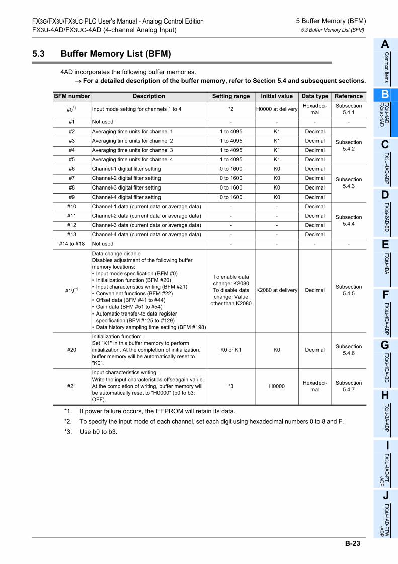
5 Buffer Memory (BFM)5.3 Buffer Memory List (BFM)
A
Comm
on Items
B
FX3U-4ADFX3UC-4AD
C
FX3U-4AD-ADP
D
FX3G-2AD-BD
E
FX3U-4DA
F
FX3U-4DA-ADP
G
FX3G-1DA-BD
H
FX3U-3A-ADP
I
FX3U-4AD-PT -ADP
J
FX3U-4AD-PTW -ADP
FX3G/FX3U/FX3UC PLC User's Manual - Analog Control EditionFX3U-4AD/FX3UC-4AD (4-channel Analog Input)
5.3 Buffer Memory List (BFM)
4AD incorporates the following buffer memories.→ For a detailed description of the buffer memory, refer to Section 5.4 and subsequent sections.
*1. If power failure occurs, the EEPROM will retain its data.*2. To specify the input mode of each channel, set each digit using hexadecimal numbers 0 to 8 and F.*3. Use b0 to b3.
BFM number Description Setting range Initial value Data type Reference
#0*1 Input mode setting for channels 1 to 4 *2 H0000 at delivery Hexadeci-mal
Subsection 5.4.1
#1 Not used - - - -
#2 Averaging time units for channel 1 1 to 4095 K1 Decimal
Subsection 5.4.2
#3 Averaging time units for channel 2 1 to 4095 K1 Decimal
#4 Averaging time units for channel 3 1 to 4095 K1 Decimal
#5 Averaging time units for channel 4 1 to 4095 K1 Decimal
#6 Channel-1 digital filter setting 0 to 1600 K0 Decimal
Subsection 5.4.3
#7 Channel-2 digital filter setting 0 to 1600 K0 Decimal
#8 Channel-3 digital filter setting 0 to 1600 K0 Decimal
#9 Channel-4 digital filter setting 0 to 1600 K0 Decimal
#10 Channel-1 data (current data or average data) - - Decimal
Subsection 5.4.4
#11 Channel-2 data (current data or average data) - - Decimal
#12 Channel-3 data (current data or average data) - - Decimal
#13 Channel-4 data (current data or average data) - - Decimal
#14 to #18 Not used - - - -
#19*1
Data change disableDisables adjustment of the following buffer memory locations:• Input mode specification (BFM #0)• Initialization function (BFM #20)• Input characteristics writing (BFM #21)• Convenient functions (BFM #22)• Offset data (BFM #41 to #44)• Gain data (BFM #51 to #54)• Automatic transfer-to data register
specification (BFM #125 to #129)• Data history sampling time setting (BFM #198)
To enable data change: K2080To disable data change: Value
other than K2080
K2080 at delivery Decimal Subsection 5.4.5
#20
Initialization function:Set "K1" in this buffer memory to perform initialization. At the completion of initialization, buffer memory will be automatically reset to "K0".
K0 or K1 K0 Decimal Subsection 5.4.6
#21
Input characteristics writing:Write the input characteristics offset/gain value. At the completion of writing, buffer memory will be automatically reset to "H0000" (b0 to b3: OFF).
*3 H0000 Hexadeci-mal
Subsection 5.4.7
B-23

5 Buffer Memory (BFM)5.3 Buffer Memory List (BFM)
FX3G/FX3U/FX3UC PLC User's Manual - Analog Control EditionFX3U-4AD/FX3UC-4AD (4-channel Analog Input)
*1. If power failure occurs, the EEPROM will retain its data.*2. Use b0 to b7.*3. The offset and gain values should satisfy the following conditions: Gain value - Offset value ≥ 1000*4. The offset and gain values should satisfy the following conditions: 30000 ≥ Gain value - Offset value ≥ 3000
BFM number Description Setting range Initial value Data type Reference
#22*1
Convenient function setting:Convenient functions:Automatic send function, data addition, upper/lower limit detection, abrupt change detection, peak value holding
*2 H0000 at delivery Hexadeci-mal
Subsection 5.4.8
#23 to #25 Not used - - - -
#26 Upper/lower limit value error status (Valid if b1 of BFM #22 is set to ON) - H0000 Hexadeci-
malSubsection
5.4.9
#27 Abrupt change detection status (Valid if b2 of BFM #22 is set to ON) - H0000 Hexadeci-
malSubsection
5.4.10
#28 Over-scale status - H0000 Hexadeci-mal
Subsection 5.4.11
#29 Error status - H0000 Hexadeci-mal
Subsection 5.4.12
#30 Model code K2080 - K2080 Decimal Subsection 5.4.13
#31 to #40 Not used - - - -
#41*1 Channel-1 offset data (Unit: mV or µA)BFM #21 will be used for writing data.
• Voltage input:-10000 to +9000*3
• Current input:-20000 to +17000*4
K0 at delivery Decimal
Subsection 5.4.14
#42*1 Channel-2 offset data (Unit: mV or µA) K0 at delivery Decimal
#43*1 Channel-3 offset data (Unit: mV or µA) K0 at delivery Decimal
#44*1 Channel-4 offset data (Unit: mV or µA) K0 at delivery Decimal
#45 to #50 Not used - - - -
#51*1 Channel-1 gain data (Unit: mV or µA)BFM #21 will be used for writing data.
• Voltage input:-9000 to +10000*3
• Current input:-17000 to +30000*4
K5000 at delivery Decimal
Subsection5.4.14
#52*1 Channel-2 gain data (Unit: mV or µA) K5000 at delivery Decimal
#53*1 Channel-3 gain data (Unit: mV or µA) K5000 at delivery Decimal
#54*1 Channel-4 gain data (Unit: mV or µA) K5000 at delivery Decimal
#55 to #60 Not used - - - -
#61 Channel-1 addition data (Valid if b0 of BFM #22 is set to ON) -16000 to +16000 K0 Decimal
Subsection 5.4.15
#62 Channel-2 addition data (Valid if b0 of BFM #22 is set to ON) -16000 to +16000 K0 Decimal
#63 Channel-3 addition data (Valid if b0 of BFM #22 is set to ON) -16000 to +16000 K0 Decimal
#64 Channel-4 addition data (Valid if b0 of BFM #22 is set to ON) -16000 to +16000 K0 Decimal
#65 to #70 Not used - - - -
#71 Channel-1 lower limit value error setting (Valid if b1 of BFM #22 is set to ON)
From minimum digital value in input range to upper limit value error setting value
Minimum digital value in input
rangeDecimal
Subsection 5.4.16
#72 Channel-2 lower limit value error setting (Valid if b1 of BFM #22 is set to ON)
Minimum digital value in input
rangeDecimal
#73 Channel-3 lower limit value error setting (Valid if b1 of BFM #22 is set to ON)
Minimum digital value in input
rangeDecimal
#74 Channel-4 lower limit value error setting (Valid if b1 of BFM #22 is set to ON)
Minimum digital value in input
rangeDecimal
#75 to #80 Not used - - - -
B-24
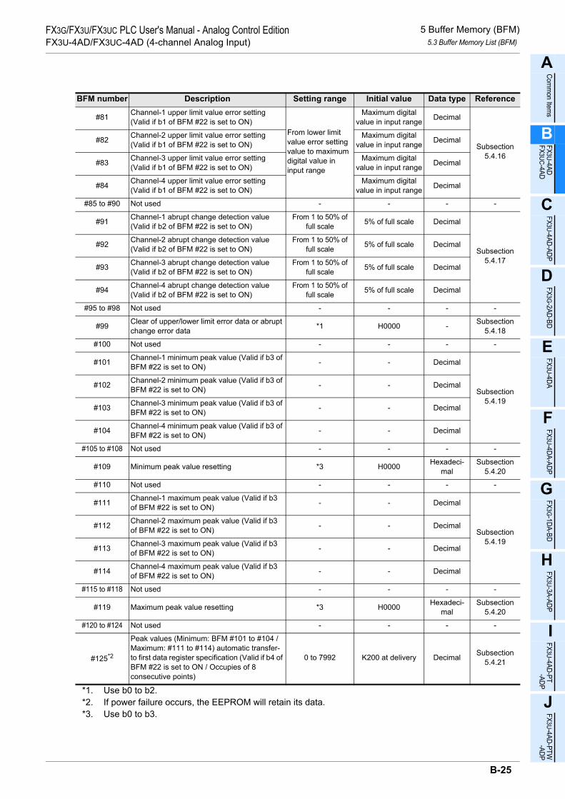
5 Buffer Memory (BFM)5.3 Buffer Memory List (BFM)
A
Comm
on Items
B
FX3U-4ADFX3UC-4AD
C
FX3U-4AD-ADP
D
FX3G-2AD-BD
E
FX3U-4DA
F
FX3U-4DA-ADP
G
FX3G-1DA-BD
H
FX3U-3A-ADP
I
FX3U-4AD-PT -ADP
J
FX3U-4AD-PTW -ADP
FX3G/FX3U/FX3UC PLC User's Manual - Analog Control EditionFX3U-4AD/FX3UC-4AD (4-channel Analog Input)
BFM number Description Setting range Initial value Data type Reference
#81 Channel-1 upper limit value error setting (Valid if b1 of BFM #22 is set to ON)
From lower limit value error setting value to maximum digital value in input range
Maximum digital value in input range Decimal
Subsection 5.4.16
#82 Channel-2 upper limit value error setting (Valid if b1 of BFM #22 is set to ON)
Maximum digital value in input range Decimal
#83 Channel-3 upper limit value error setting (Valid if b1 of BFM #22 is set to ON)
Maximum digital value in input range Decimal
#84 Channel-4 upper limit value error setting (Valid if b1 of BFM #22 is set to ON)
Maximum digital value in input range Decimal
#85 to #90 Not used - - - -
#91 Channel-1 abrupt change detection value (Valid if b2 of BFM #22 is set to ON)
From 1 to 50% of full scale 5% of full scale Decimal
Subsection 5.4.17
#92 Channel-2 abrupt change detection value (Valid if b2 of BFM #22 is set to ON)
From 1 to 50% of full scale 5% of full scale Decimal
#93 Channel-3 abrupt change detection value (Valid if b2 of BFM #22 is set to ON)
From 1 to 50% of full scale 5% of full scale Decimal
#94 Channel-4 abrupt change detection value (Valid if b2 of BFM #22 is set to ON)
From 1 to 50% of full scale 5% of full scale Decimal
#95 to #98 Not used - - - -
#99 Clear of upper/lower limit error data or abrupt change error data *1 H0000 - Subsection
5.4.18
#100 Not used - - - -
#101 Channel-1 minimum peak value (Valid if b3 of BFM #22 is set to ON) - - Decimal
Subsection 5.4.19
#102 Channel-2 minimum peak value (Valid if b3 of BFM #22 is set to ON) - - Decimal
#103 Channel-3 minimum peak value (Valid if b3 of BFM #22 is set to ON) - - Decimal
#104 Channel-4 minimum peak value (Valid if b3 of BFM #22 is set to ON) - - Decimal
#105 to #108 Not used - - - -
#109 Minimum peak value resetting *3 H0000 Hexadeci-mal
Subsection 5.4.20
#110 Not used - - - -
#111 Channel-1 maximum peak value (Valid if b3 of BFM #22 is set to ON) - - Decimal
Subsection 5.4.19
#112 Channel-2 maximum peak value (Valid if b3 of BFM #22 is set to ON) - - Decimal
#113 Channel-3 maximum peak value (Valid if b3 of BFM #22 is set to ON) - - Decimal
#114 Channel-4 maximum peak value (Valid if b3 of BFM #22 is set to ON) - - Decimal
#115 to #118 Not used - - - -
#119 Maximum peak value resetting *3 H0000 Hexadeci-mal
Subsection 5.4.20
#120 to #124 Not used - - - -
#125*2
Peak values (Minimum: BFM #101 to #104 / Maximum: #111 to #114) automatic transfer-to first data register specification (Valid if b4 of BFM #22 is set to ON / Occupies of 8 consecutive points)
0 to 7992 K200 at delivery Decimal Subsection 5.4.21
*1. Use b0 to b2.*2. If power failure occurs, the EEPROM will retain its data.*3. Use b0 to b3.
B-25

5 Buffer Memory (BFM)5.3 Buffer Memory List (BFM)
FX3G/FX3U/FX3UC PLC User's Manual - Analog Control EditionFX3U-4AD/FX3UC-4AD (4-channel Analog Input)
BFM number Description Setting range Initial value Data type Reference
#126*1Upper/lower limit error status data (BFM #26) automatic transfer-to data register specification (Valid if b5 of BFM #22 is set to ON)
0 to 7999 K208 at delivery Decimal Subsection 5.4.22
#127*1Abrupt change detection status data (BFM #27) automatic transfer-to data register specification (Valid if b6 of BFM #22 is set to ON)
0 to 7999 K209 at delivery Decimal Subsection 5.4.23
#128*1Over-scale status data (BFM #28) automatic transfer-to data register specification (Valid if b7 of BFM #22 is set to ON)
0 to 7999 K210 at delivery Decimal Subsection 5.4.24
#129*1Error status data (BFM #29) automatic transfer-to data register specification (Valid if b8 of BFM #22 is set to ON)
0 to 7999 K211 at delivery Decimal Subsection 5.4.25
#130 to #196 Not used - - - -
#197 Selection of cyclic data update function (function for data history) *2 H0000 Hexadeci-
malSubsection
5.4.26
#198*1 Data history sampling time setting (Unit: ms) 0 to 30000 K15000 Decimal Subsection 5.4.27
#199 Data history resetting/stoppage *3 H0000 Hexadeci-mal
Subsection 5.4.28
#200 Channel-1 data history (initial value) - K0 Decimal
Subsection 5.4.29
~ ~ ~ ~ Decimal
#1899 Channel-1 data history (1,700th value) - K0 Decimal
#1900 Channel-2 data history (initial value) - K0 Decimal
~ ~ ~ ~ Decimal
#3599 Channel-2 data history (1,700th value) - K0 Decimal
#3600 Channel-3 data history (initial value) - K0 Decimal
~ ~ ~ ~ Decimal
#5299 Channel-3 data history (1,700th value) - K0 Decimal
#5300 Channel-4 data history (initial value) - K0 Decimal
~ ~ ~ ~ Decimal
#6999 Channel-4 data history (1,700th value) - K0 Decimal
#7000 to #8063 System area - - - -
*1. If power failure occurs, the EEPROM will retain its data.*2. Use b0 to b3.*3. Use b0 to b3 and b8 to b11.
B-26

5 Buffer Memory (BFM)5.4 Buffer Memory Details
A
Comm
on Items
B
FX3U-4ADFX3UC-4AD
C
FX3U-4AD-ADP
D
FX3G-2AD-BD
E
FX3U-4DA
F
FX3U-4DA-ADP
G
FX3G-1DA-BD
H
FX3U-3A-ADP
I
FX3U-4AD-PT -ADP
J
FX3U-4AD-PTW -ADP
FX3G/FX3U/FX3UC PLC User's Manual - Analog Control EditionFX3U-4AD/FX3UC-4AD (4-channel Analog Input)
5.4 Buffer Memory Details
5.4.1 BFM #0: Input mode specification
Initial value (at delivery): H0000Numeric data type: Hexadecimal (H)
Specify the input modes of channel 1 to 4.4 hexadecimal digits are assigned to specify the input modes of the 4 channels. Change the value of each digit to change the input mode of each channel. 0 to 8 or F can be set for each digit.
The different types of input modes are shown in the following table:→ For a detailed description of input characteristics, refer to Section 2.4.
*1. The offset/gain values cannot be changed.
1. Cautions regarding input mode setting• If the input mode is set (changed), the analog input characteristics will be changed automatically.
Furthermore, when the offset/gain value is changed, the characteristics can be set to the desired values. (The resolution cannot be changed.)
• If the analog value direct indication (*1) is specified, the offset/gain value cannot be changed.• It takes approximately 5 seconds to determine the input mode. For this reason, after changing the input
mode, be sure to wait for 5 seconds or more before writing other data.• HFFFF (no channels used) cannot be set.
2. Caution regarding EEPROM writingIf data is written to BFM #0, #19, #21, #22, #125 to #129, or #198, the data will also be written to the 4ADEEPROM.The maximum number of EEPROM rewrites is 10,000 times. Therefore, when creating a program, do notfrequently write data to the above buffer memories (BFM).
Set value[HEX] Input mode Analog input
rangeDigital output
range0 Voltage input mode -10V to +10V -32000 to +32000
1 Voltage input mode -10V to +10V -4000 to +4000
2*1 Voltage inputAnalog value direct indication mode -10V to +10V -10000 to +10000
3 Current input mode 4mA to 20mA 0 to 16000
4 Current input mode 4mA to 20mA 0 to 4000
5*1 Current inputAnalog value direct indication mode 4mA to 20mA 4000 to 20000
6 Current input mode -20mA to +20mA -16000 to +16000
7 Current input mode -20mA to +20mA -4000 to +4000
8*1 Current inputAnalog value direct indication mode -20mA to +20mA -20000 to +20000
9 to E Setting not possible - -
F Channel not used - -
Hch4ch3 ch2
ch1
B-27

5 Buffer Memory (BFM)5.4 Buffer Memory Details
FX3G/FX3U/FX3UC PLC User's Manual - Analog Control EditionFX3U-4AD/FX3UC-4AD (4-channel Analog Input)
5.4.2 BFM #2 to #5: Averaging time
Setting range: 1 to 4095Initial value: K1
Numeric data type: Decimal (K)
To change the channel data type from the immediate data (channels 1 to 4: BFM #10 to #13) to the averagedata, set the desired averaging time (channels 1 to 4 : BFM #2 to 5).The relation between the set averaging time and the corresponding operation is shown in the following table.
→ For a detailed description of channel data update timing, refer to Subsection 5.4.4.
1. ApplicationIf the measurement signal contains comparatively reduced ripple noise, such as supply voltage frequency,averaging will result in obtaining of stable data.
2. Cautions regarding averaging time setting• To use the averaging function, be sure to set the digital filter of the corresponding channel to "0". (Digital
filter setting: BFM #6 to #9 for channels 1 to 4)To use the digital filter function, be sure to set the averaging time of the corresponding channel to "1". (Averaging time: BFM #2 to #5 for channels 1 to 4)If the averaging time is set to a value other than "1" and the digital filter (BFM #6 to #9 for channels 1 to 4) is set to a value other than "0", the digital filter setting error (b11 of BFM #29) will occur.
• If one of the channels uses the digital filter, the A/D conversion time will be set to 5 ms for all the channels.• If the averaging time is out of the setting range, the averaging time setting error (b10 of BFM #29) will
occur.• If the averaging time is set, the data history function cannot be used.
Averaging time (BFM #2 to #5)
Channel data (BFM #10 to #13) type Error descriptions
0 or lessImmediate data(Each time the A/D conversion is performed, the channel data will be updated.)
K0 will be set, and the averaging time setting error (b10 of BFM #29) will occur.
1 (initial value)
Immediate data(Each time the A/D conversion is performed, the channel data will be updated.)
-
2 to 400
Average data(Each time the A/D conversion is performed, the average value will be calculated and the channel data will be updated.)
-
401 to 4095
Average data(Each time the A/D conversion data reaches the averaging time, the average data will be calculated and the channel data will be updated.)
-
4096 or moreAverage data(Each time the A/D conversion is performed, the channel data will be updated.)
4096 will be set, and the averaging time setting error (b10 of BFM #29) will occur.
B-28

5 Buffer Memory (BFM)5.4 Buffer Memory Details
A
Comm
on Items
B
FX3U-4ADFX3UC-4AD
C
FX3U-4AD-ADP
D
FX3G-2AD-BD
E
FX3U-4DA
F
FX3U-4DA-ADP
G
FX3G-1DA-BD
H
FX3U-3A-ADP
I
FX3U-4AD-PT -ADP
J
FX3U-4AD-PTW -ADP
FX3G/FX3U/FX3UC PLC User's Manual - Analog Control EditionFX3U-4AD/FX3UC-4AD (4-channel Analog Input)
5.4.3 BFM #6 to #9: Digital filter setting
Setting range: 0 to 1600Initial value: K0
Numeric data type: Decimal (K)
To use the digital filter for channel data (BFM #10 to #13 for channels 1 to 4), set the digital filter value in thecorresponding buffer memory (BFM #6 to #9 for channels 1 to 4).
→ For a detailed description of channel data update timing, refer to Subsection 5.4.4.If the digital filter function is used, the relation between the analog input value and the set digital filter value orthe digital output value (channel data) will be as follows:• Digital filter value (BFM #6 to #9 for channels 1 to 4) > Fluctuation of analog signal (fluctuation
width: less than 10 times of sampling)If the fluctuation of the analog signal (input value) is less than the set digital filter value, the analog input value will be converted into a stabilized digital output value and stored in the corresponding buffer memory (BFM #10 to #13 for channels 1 to 4).
• Digital filter value (BFM #6 to #9 for channels 1 to 4) < Fluctuation of analog signalIf the fluctuation of the analog signal (input value) is more than the set digital filter value, the digital output value will follow the analog input value, and the digital output value equal to the analog input value will be stored in the corresponding buffer memory (BFM #10 to #13 for channels 1 to 4).
The relation between the set value and the corresponding operation is shown in the following table:
1. ApplicationIf the measurement signal contains steep spike noise, use the digital filter instead of the averaging function.The digital filter produces more stabilized data results.
2. Cautions regarding digital filter setting• To use the digital filter function, be sure to set the averaging time of the corresponding channel to "1".
(Averaging time: BFM #2 to #5 for channels 1 to 4) If the averaging time is set to a value other than "1" and the digital filter is set to a value other than "0", the digital filter setting error (b11 of BFM #29) will occur.
• If one of the channels uses the digital filter, the A/D conversion time will be set to 5 ms for all the channels.• If the digital filter set value is not in the range from 0 to 1600, the digital filter setting error (b11 of BFM #29)
will occur.
Set value OperationLess than 0 Disables the digital filter function. A setting error will occur (b11 of BFM #29 will be set to ON).
0 Disables the digital filter function.
1 to 1600 Enables the digital filter function.
1601 or more Disables the digital filter function. A setting error will occur (b11 of BFM #29 will be set to ON).
Set digital filter value
Converted into stabilized digital output value(Fluctuation width is less than 10 times of sampling)
Time
Anal
og in
put v
alue
The digital output value willfollow the analog input value.
Analog input valueDigital output value
Set digital filter value
B-29

5 Buffer Memory (BFM)5.4 Buffer Memory Details
FX3G/FX3U/FX3UC PLC User's Manual - Analog Control EditionFX3U-4AD/FX3UC-4AD (4-channel Analog Input)
5.4.4 BFM #10 to #13: Channel data
Numeric data type: Decimal (K)
Use these buffer memories to store the A/D converted digital values.The channel data (BFM #10 to #13 for channels 1 to 4) and the data update timing will depend on the setaveraging time (BFM #2 to #5 for channels 1 to 4) or the digital filter setting condition (BFM #6 to #9 forchannels 1 to 4) as shown in the following table.
→ For a detailed description of the averaging time, refer to Subsection 5.4.2.→ For a detailed description of digital filter functions, refer to Subsection 5.4.3.
*1. "500µs" represents the A/D conversion time.However, if one of the channels uses the digital filter function, the A/D conversion time will be 5 ms forall the channels.
Averaging time
(BFM #2 to #5)
Digital filter function
(BFM #6 to #9)
Channel data (BFM #10 to #13) update timing
Channel data type Update timing
0 or less 0 (The digital filter will not be used.)
Immediate data"0" will be set, and the averaging time setting error (b10 of BFM #29) will occur.
Each time the A/D conversion is performed, the data will be updated.The update timing will be as follows:
Update time = 500µs*1 × Number of selected channels
1
0 (The digital filter will not be used.) Immediate data
1 to 1600(The digital filter will be used.)
Immediate dataThe digital filter function will be used.
Each time the A/D conversion is performed, the data will be updated.The update timing will be as follows:
Update time = 5ms × Number of selected channels
2 to 400
0 (The digital filter will not be used.)
Average data
Each time the A/D conversion is performed, the data will be updated.The update timing will be as follows:
Update time = 500µs*1× Number of selected channels
401 to 4095 Average data Each time the A/D conversion is performed for the set averaging time, the data will be updated. The update timing will be as follows:
Update time = 500µs*1 × Number of selected channels × Averaging time
4096 or more
Average data"4096" will be set, and the averaging time setting error (b10 of BFM #29) will occur.
B-30

5 Buffer Memory (BFM)5.4 Buffer Memory Details
A
Comm
on Items
B
FX3U-4ADFX3UC-4AD
C
FX3U-4AD-ADP
D
FX3G-2AD-BD
E
FX3U-4DA
F
FX3U-4DA-ADP
G
FX3G-1DA-BD
H
FX3U-3A-ADP
I
FX3U-4AD-PT -ADP
J
FX3U-4AD-PTW -ADP
FX3G/FX3U/FX3UC PLC User's Manual - Analog Control EditionFX3U-4AD/FX3UC-4AD (4-channel Analog Input)
5.4.5 BFM #19: Data change disable
Setting range: K2080, or value other than K2080Initial value (at delivery): K2080Numeric data type: Decimal (K)
Disables adjustment of the following BFMs:• Input mode specification (BFM #0) • Initialization function (BFM #20)• Input characteristics writing (BFM #21) • Convenient functions (BFM #22)• Offset data (BFM #41 to #44) • Gain data (BFM #51 to #54)• Automatic transfer-to data register specification (BFM #125 to #129)• Data history sampling time setting (BFM #198)
Set the value of BFM #19 (Data change disable) as follows:
1. Caution regarding EEPROM writingIf data is written to BFM #0, #19, #21, #22, #125 to #129, or #198, the data will also be written to the 4ADEEPROM.
→ For a detailed description of caution regarding EEPROM writing, refer to Subsection 5.4.1.
5.4.6 BFM #20: Initialization function (resetting to factory default status)
Setting range: K0 or K1Initial value: K0
Numeric data type: Decimal (K)
Use this function to initialize all data in BFM #0 to #6999, to the factory default status.
Set "K1" to initialize all data. When initialization is complete, "K0" will be set automatically.
1. Caution regarding initialization function setting• It takes approximately 5 seconds to initialize all the data.• Priority is given to BFM #19 which prevents a data from being changed. To initialize, set K2080 in BFM #19.
5.4.7 BFM #21: Input characteristics writing
Initial value: H0000Numeric data type: Hexadecimal (H)
Channel numbers are assigned to the 4 lower bits of BFM #21. If any of these bits are turned on, the offsetdata (BFM #41 to #44) and gain data (BFM #51 to #54) of the corresponding channel will be written to theinternal memory (EEPROM). When written to the internal memory, the data will become valid.
1. BFM #21 bits channel number assignment
The WRITE command can be given to two or more channels at the same time. (Set "H000F" to write allchannel data to the EEPROM.) When writing is complete, "H0000" (b0 to b3: OFF) will be set automatically.
Set value DescriptionK2080 Data change enabled.
Value other than K2080 Data change disabled.
Set value DescriptionK0 Normal
K1 Initializes all data
Bit No. Descriptionb0 Channel-1 offset data (BFM #41) and gain data (BFM #51) writing
b1 Channel-2 offset data (BFM #42) and gain data (BFM #52) writing
b2 Channel-3 offset data (BFM #43) and gain data (BFM #53) writing
b3 Channel-4 offset data (BFM #44) and gain data (BFM #54) writing
b4 to b15 Not used.
B-31

5 Buffer Memory (BFM)5.4 Buffer Memory Details
FX3G/FX3U/FX3UC PLC User's Manual - Analog Control EditionFX3U-4AD/FX3UC-4AD (4-channel Analog Input)
5.4.8 BFM #22: Convenient function setting
Initial value: H0000Numeric data type: Hexadecimal (H)
Turn on each bit (b0 to b8) of BFM #22 to enable the function assigned to each bit (refer to the followingtable). Turn off each bit to disable the function of each bit.
1. Function assigned to each bit of BFM #22Bit No. Function Description Reference
b0 Data addition function
The channel data (BFM #10 to #13), peak data (BFM #101 to #104, #111 to #114), and data history (BFM #200 to #6999) will be subject to change (the addition data (BFM #61 to #64) will be added to the measurement data).When setting the lower limit error data (BFM #71 to #74) or the upper limit error data (BFM #81 to #84), add the addition data (BFM #61 to #64) to the error data to be set.
Subsection 5.4.15
b1 Upper/lower limit detection function
If the A/D conversion data of a channel is outside the range set by the lower limit error data (BFM #71 to #74) and the upper limit error data (BFM #81 to #84), the result will be written to BFM #26 as the upper/lower limit error status data.
Subsection 5.4.16
b2 Abrupt change detection function
When channel data (BFM #10 to #13) is updated, if the difference between the previous value and the new value is larger than the set abrupt change detection value (value set in BFM #91 to #94), the result will be written to BFM #27 as the abrupt change detection status data.
Subsection 5.4.17
b3 Peak value holding function
The minimum value of channel data written to BFM #10 to #13 will be written to BFM #101 to #104 as the minimum peak value, and the maximum value of channel data written to BFM #10 to #13 will be written to BFM #111 to #114 as the maximum peak value.
Subsection 5.4.19
b4 Peak value automatic transfer function
If the automatic transfer-to first data register is specified in BFM #125, the minimum peak value (BFM #101 to #104) and the maximum peak value (BFM #111 to #114) will be automatically written to the specified data registers (8 points (registers) starting from the first data register specified).
Subsection 5.4.19
Subsection 5.4.21
b5Upper/lower limit error status data automatic transfer function
If the upper/lower limit error status data automatic transfer-to data register is specified in BFM #126, the upper/lower limit error status data (BFM #26) will be automatically written to the specified data register.
Subsection 5.4.16
Subsection 5.4.22
b6
Abrupt change detection status data automatic transfer function
If the abrupt change detection status data automatic transfer-to data register is specified in BFM #127, the abrupt change detection status data (BFM #27) will be automatically written to the specified data register.
Subsection 5.4.17
Subsection 5.4.23
b7Over-scale status data automatic transfer function
If the over-scale status data automatic transfer-to data register is specified in BFM #128, the over-scale status data (BFM #28) will be automatically written to the specified data register.
Subsection 5.4.24
b8Error status data automatic transfer function
If the error status data automatic transfer to data register is specified in BFM #129, the error status data (BFM #29) will be automatically written to the specified data register.
Subsection 5.4.25
b9 to b15 - Not used. -
B-32

5 Buffer Memory (BFM)5.4 Buffer Memory Details
A
Comm
on Items
B
FX3U-4ADFX3UC-4AD
C
FX3U-4AD-ADP
D
FX3G-2AD-BD
E
FX3U-4DA
F
FX3U-4DA-ADP
G
FX3G-1DA-BD
H
FX3U-3A-ADP
I
FX3U-4AD-PT -ADP
J
FX3U-4AD-PTW -ADP
FX3G/FX3U/FX3UC PLC User's Manual - Analog Control EditionFX3U-4AD/FX3UC-4AD (4-channel Analog Input)
2. Caution regarding convenient function setting• Even if the data addition function is used, the value before adding the addition data (BFM #61 to #64) will
be checked to detect the over-scale error.• To use the peak value automatic transfer function (b4 of BFM #22), be sure to enable the peak value
holding function (b3 of BFM #22).• To use the upper/lower limit error status data automatic transfer function (b5 of BFM #22), be sure to
enable the upper/lower limit value detection function (b1 of BFM #22).• To use the abrupt change detection status data automatic transfer function (b6 of BFM #22), be sure to
enable the abrupt change detection function (b2 of BFM #22).
3. Caution regarding EEPROM writingIf data is written to BFM #0, #19, #21, #22, #125 to #129, or #198, the data will also be written to the 4ADEEPROM.
→ For a detailed description of caution regarding EEPROM writing, refer to Subsection 5.4.1.
B-33
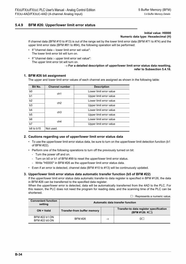
5 Buffer Memory (BFM)5.4 Buffer Memory Details
FX3G/FX3U/FX3UC PLC User's Manual - Analog Control EditionFX3U-4AD/FX3UC-4AD (4-channel Analog Input)
5.4.9 BFM #26: Upper/lower limit error status
Initial value: H0000Numeric data type: Hexadecimal (H)
If channel data (BFM #10 to #13) is out of the range set by the lower limit error data (BFM #71 to #74) and theupper limit error data (BFM #81 to #84), the following operation will be performed:• If "channel data < lower limit error set value":
The lower limit error bit will turn on.• If "channel data > upper limit error set value":
The upper limit error bit will turn on.→ For a detailed description of upper/lower limit error status data resetting,
refer to Subsection 5.4.18.
1. BFM #26 bit assignmentThe upper and lower limit error values of each channel are assigned as shown in the following table:
2. Cautions regarding use of upper/lower limit error status data• To use the upper/lower limit error status data, be sure to turn on the upper/lower limit detection function (b1
of BFM #22).• Perform one of the following operations to turn off the previously turned on bit:
- Turn the power off and on.- Turn on b0 or b1 of BFM #99 to reset the upper/lower limit error status.- Write "H0000" in BFM #26 as the upper/lower limit error status data.
• Even if an error is detected, channel data (BFM #10 to #13) will be continuously updated.
3. Upper/lower limit error status data automatic transfer function (b5 of BFM #22)If the upper/lower limit error status data automatic transfer-to data register is specified in BFM #126, the datain BFM #26 can be transferred to the specified data register.When the upper/lower error is detected, data will be automatically transferred from the 4AD to the PLC. Forthis reason, the PLC does not need the program for reading data, and the scanning time of the PLC can beshortened.
: Represents a numeric value.
Bit No. Channel number Descriptionb0
ch1Lower limit error value
b1 Upper limit error value
b2ch2
Lower limit error value
b3 Upper limit error value
b4ch3
Lower limit error value
b5 Upper limit error value
b6ch4
Lower limit error value
b7 Upper limit error value
b8 to b15 Not used.
Convenient function setting Automatic data transfer function
ON = Valid Transfer-from buffer memory Transfer-to data register specification (BFM #126: K )
BFM #22 b1:ONBFM #22 b5:ON BFM #26 → D
B-34

5 Buffer Memory (BFM)5.4 Buffer Memory Details
A
Comm
on Items
B
FX3U-4ADFX3UC-4AD
C
FX3U-4AD-ADP
D
FX3G-2AD-BD
E
FX3U-4DA
F
FX3U-4DA-ADP
G
FX3G-1DA-BD
H
FX3U-3A-ADP
I
FX3U-4AD-PT -ADP
J
FX3U-4AD-PTW -ADP
FX3G/FX3U/FX3UC PLC User's Manual - Analog Control EditionFX3U-4AD/FX3UC-4AD (4-channel Analog Input)
5.4.10 BFM #27: Abrupt change detection status
Initial value: H0000Numeric data type: Hexadecimal (H)
When channel data (BFM #10 to #13) is updated, if the difference between the previous value and the newvalue is larger than the set abrupt change detection value (value set in BFM #91 to #94), the followingoperation will be performed:• If "(new value) - (previous value) > (abrupt change detection value)":
The "+" direction bit will turn on.• If "(previous value) - (new value) > (abrupt change detection value)":
The "-" direction bit will turn on.→ For a detailed description of abrupt change detection status data resetting,
refer to Subsection 5.4.18.
1. Assignment of each bit of BFM #27For the abrupt change detection function of each channel, the "+" and "-" directions are assigned as shown inthe following table:
2. Caution regarding use of abrupt change detection status data• To use the abrupt change status data, be sure to turn on the abrupt change detection function (b2 of BFM
#22).• Perform one of the following operations to turn off the previously turned on bit:
- Turn the power off and on.- Turn on b2 of BFM #99 to reset the abrupt change detection error status.- Write "H0000" in BFM #27 as the abrupt change detection status data.
• Even if abrupt change is detected, channel data (BFM #10 to #13) will be continuously updated.
3. Abrupt change detection status data automatic transfer function (b6 of BFM #22)If the abrupt change detection status data automatic transfer-to data register is specified in BFM #127, thedata in BFM #27 can be transferred to the specified data register.When abrupt change is detected, data will be automatically transferred from the 4AD to the PLC. For thisreason, the PLC does not need any program for reading the data, and the scan time of the PLC can beshortened.
: Represents a numeric value.
Bit No. Channel number Descriptionb0
ch1"-" direction for abrupt change detection
b1 "+" direction for abrupt change detection
b2ch2
"-" direction for abrupt change detection
b3 "+" direction for abrupt change detection
b4ch3
"-" direction for abrupt change detection
b5 "+" direction for abrupt change detection
b6ch4
"-" direction for abrupt change detection
b7 "+" direction for abrupt change detection
b8 to b15 Not used.
Convenient function setting Automatic data transfer function
ON = Valid Transfer-from memory Transfer-to data register specification (BFM #127: K )
BFM #22 b2:ONBFM #22 b6:ON BFM #27 → D
B-35

5 Buffer Memory (BFM)5.4 Buffer Memory Details
FX3G/FX3U/FX3UC PLC User's Manual - Analog Control EditionFX3U-4AD/FX3UC-4AD (4-channel Analog Input)
5.4.11 BFM #28: Over-scale status
Initial value: H0000Numeric data type: Hexadecimal (H)
If the input analog value is out of the A/D conversion range, the following operation will be performed:• If "(analog input value) < (lower limit value in A/D conversion range)":
The over-scale lower limit bit will turn on.• If "(analog input value) < (upper limit value in A/D conversion range)":
The over-scale upper limit bit will turn on.
1. A/D conversion range
2. Assignment of each bit of BFM #28
3. Caution regarding use of over-scale status data• Perform one of the following operations to turn off the previously turned on bit:
- Turn the power off and on.- Write "H0000" in BFM #28 as the over-scale status data.
• Even if over scale is detected, channel data (BFM #10 to #13) will continuously be updated.
4. Over-scale status data automatic transfer function (b7 of BFM #22)If the over-scale status data automatic transfer-to data register is specified in BFM #128, the data in BFM #28can be transferred to the specified data register.When over-scale is detected, data will be automatically transferred from the 4AD to the PLC. For this reason,the PLC does not need any program for reading the data, and the scan time of the PLC can be shortened.
: Represents a numeric value.
Input type A/D conversion rangeVoltage input -10.2V to +10.2V
Current input -20.4mA to +20.4mA
Bit No. Channel number Descriptionb0
ch1Over-scale (lower limit)
b1 Over-scale (upper limit)
b2ch2
Over-scale (lower limit)
b3 Over-scale (upper limit)
b4ch3
Over-scale (lower limit)
b5 Over-scale (upper limit)
b6ch4
Over-scale (lower limit)
b7 Over-scale (upper limit)
b8 to b15 Not used.
Convenient function setting Automatic data transfer function
ON = Valid Transfer-from memory Transfer-to data register specification (BFM #128: K )
BFM #22 b7:ON BFM #28 → D
B-36

5 Buffer Memory (BFM)5.4 Buffer Memory Details
A
Comm
on Items
B
FX3U-4ADFX3UC-4AD
C
FX3U-4AD-ADP
D
FX3G-2AD-BD
E
FX3U-4DA
F
FX3U-4DA-ADP
G
FX3G-1DA-BD
H
FX3U-3A-ADP
I
FX3U-4AD-PT -ADP
J
FX3U-4AD-PTW -ADP
FX3G/FX3U/FX3UC PLC User's Manual - Analog Control EditionFX3U-4AD/FX3UC-4AD (4-channel Analog Input)
5.4.12 BFM #29: Error status
Initial value: H0000Numeric data type: Hexadecimal (H)
Error data is assigned to the bits of BFM #29.
2. Caution regarding error statusIf the error cause is eliminated, the error bit will turn off.Do not directly write "H0000" in BFM #29 using a sequence program.
3. Error status data automatic transfer function (b8 of BFM #22)If the error status data automatic transfer-to data register is specified in BFM #129, the data in BFM #29 canbe transferred to the specified data register.When an error is detected, data will be automatically transferred from 4AD to the PLC. For this reason, thePLC does not need any program for reading the data, and the scan time of the PLC can be shortened.
: Represents a numeric value.
1. BFM #29 Bit Assignment Bit No. Item Description
b0 Error detection If any bits between b2 and b4 are turned on, b0 will turn on.
b1 - -
b2 Power supply error The 24 V power is not supplied properly. Check the wiring condition or the voltage supplied.
b3 Hardware error FX3U-4AD/FX3UC-4AD may be defective. Please contact the nearest Mitsubishi Electric distributor office.
b4 A/D conversion errorThe A/D conversion value is abnormal.Check the over-scale status data (BFM #28) to localize the error channel.
b5 - -
b6 BFM reading/writing impossible
If change in the input characteristics is started, this bit will turn on. If this bit (b6) is on, A/D conversion data cannot be read out correctly.
b7 - -
b8 Data setting error detection If any bits between b10 and b15 are turned on, b8 will turn on.
b9 - -
b10 Averaging time setting error The averaging time (BFM #2 to #5) is not set correctly.Set the averaging time again in the range from 1 to 4095.
b11 Digital filter setting error The digital filter value (BFM #6 to #9) is not set correctly.Set the digital filter value again in the range from 0 to 1600.
b12 Abrupt change detection value setting error
The abrupt change detection value (BFM #91 to #94) is not set correctly.Correctly set the value again.
b13 Upper/lower limit error detection value setting error
The lower limit error detection value (BFM #71 to #74) or the upper limit error detection value (BFM #81 to #84) is not set correctly.Correctly set the value again.
b14 - -
b15 Addition data setting error The addition data (BFM #61 to #64) is not set correctly.Set the addition data again in the range from -16000 to +16000.
Convenient function setting Automatic data transfer function
ON = Valid Transfer-from memory Transfer-to data register specification (BFM #129: K )
BFM #22 b8:ON BFM #29 → D
B-37

5 Buffer Memory (BFM)5.4 Buffer Memory Details
FX3G/FX3U/FX3UC PLC User's Manual - Analog Control EditionFX3U-4AD/FX3UC-4AD (4-channel Analog Input)
5.4.13 BFM #30: Model code
Initial value: K2080Numeric data type: Decimal (K)
"K2080" (fixed value) is stored as the model code.
5.4.14 BFM #41 to #44: Offset data / BFM #51 to #54: Gain data
Setting range: See below.Initial value: See below.
Numeric data type: Decimal (K)
If the input mode is specified in BFM #0, the offset data and the gain data of each channel will be automatically stored. The initial offset data and gain data are set for each mode as shown in the following table:• Offset data: Analog input value when the digital value is "0" (reference offset value)• Gain data: Analog input value when the digital value is equal to the reference gain value (The
reference gain value depends on the set input mode.)
1. Reference offset/gain value and initial value set at delivery
Input mode (BFM #0)Offset
(Channels 1 to 4: BFM #41 to #44)
Gain(Channels 1 to 4: BFM #51 to
#54)Set
value Description Reference value Initial value Reference
value Initial value
0 Voltage input (-10V to +10V:-32000 to +32000) 0 0mV 16000 5000mV
1 Voltage input (-10V to +10V:-4000 to +4000) 0 0mV 2000 5000mV
2Voltage inputAnalog value direct indication mode (-10V to +10V:-10000 to +10000)
0(Data change impossible)
0mV(Data change impossible)
5000(Data change impossible)
5000mV(Data change impossible)
3 Current input (4mA to 20mA:0 to 16000) 0 4000µA 16000 20000µA
4 Current input (4mA to 20mA:0 to 4000) 0 4000µA 4000 20000µA
5Current inputAnalog value direct indication mode (4mA to 20mA:4000 to 20000)
4000(Data change impossible)
4000µA(Data change impossible)
20000(Data change impossible)
20000µA(Data change impossible)
6 Current input (-20mA to +20mA:-16000 to +16000) 0 0µA 16000 20000µA
7 Current input (-20mA to +20mA:-4000 to +4000) 0 0µA 4000 20000µA
8Current inputAnalog value direct indication mode (-20mA to +20mA:-20000 to +20000)
0(Data change impossible)
0µA(Data change impossible)
20000(Data change impossible)
20000µA(Data change impossible)
B-38

5 Buffer Memory (BFM)5.4 Buffer Memory Details
A
Comm
on Items
B
FX3U-4ADFX3UC-4AD
C
FX3U-4AD-ADP
D
FX3G-2AD-BD
E
FX3U-4DA
F
FX3U-4DA-ADP
G
FX3G-1DA-BD
H
FX3U-3A-ADP
I
FX3U-4AD-PT -ADP
J
FX3U-4AD-PTW -ADP
FX3G/FX3U/FX3UC PLC User's Manual - Analog Control EditionFX3U-4AD/FX3UC-4AD (4-channel Analog Input)
2. Offset/gain data changeSet offset data and gain data to change the input characteristics.The offset and gain data can be set for each channel. If the voltage input mode is set, write the offset and gain data in mV. If the current input mode is set, write the offset and gain data in µA.To change the offset data or gain data, turn on the corresponding bit of BFM #21 (buffer memory for input characteristics writing).The data setting range is shown in the following table:
*1. The offset and gain values should meet the following condition:
Gain value - Offset value ≥ 1000
*2. The offset and gain values should meet the following condition:
30000 ≥ Gain value - Offset value ≥ 3000
3. Cautions regarding offset/gain data change• If the analog value direct indication mode is used, the input characteristics cannot be changed.• Even if the input characteristics are changed, the actual valid input range will not be changed:
from -10V to +10V for the voltage input mode, and from -20mA to +20mA for the current input mode.• Even if the input characteristics are changed, the resolution will not increase.
→ For a detailed description of input characteristics change, refer to Chapter 6.
5.4.15 BFM #61 to #64: Addition data
Setting range: -16000 to +16000Initial value: K0
Numeric data type: Decimal (K)
If the addition data (BFM #61 to #64) is set, the set data will be added before storing the channel data (BFM#10 to #13), peak data (BFM #101 to #104, BFM #111 to #114), or data history (BFM #200 to #6999).
1. Cautions regarding addition data setting• To use the addition data, be sure to turn on the data addition function (b0 of BFM #22).• When setting the lower limit error data (BFM #71 to #74) or the upper limit error data (BFM #81 to #84),
add the addition data (BFM #61 to #64) to the error data to be set.
Voltage input (mV) Current input (µA)
Offset data -10000 to +9000*1 -20000 to +17000*2
Gain data -9000 to +10000*1 -17000 to +30000*2
B-39

5 Buffer Memory (BFM)5.4 Buffer Memory Details
FX3G/FX3U/FX3UC PLC User's Manual - Analog Control EditionFX3U-4AD/FX3UC-4AD (4-channel Analog Input)
5.4.16 BFM #71 to #74: Lower limit error setting / BFM #81 to #84: Upper limit error setting
Setting range: See below.Initial value: See below.
Numeric data type: Decimal (K)
Set the upper/lower limit error data so that the upper/lower limit error status (BFM #26) can be detected.The data setting range depends on the input mode set in BFM #0.The following table shows the data setting range for each input mode:
1. Cautions regarding upper/lower limit error setting• To use the set upper/lower limit error data, be sure to turn on the upper/lower limit error detection function
(b1 of BFM #22).• To use the data addition function (b0 of BFM #22) together with this function, be sure to add the addition
data (channels 1 to 4: BFM #61 to #64) to the upper/lower limit values to be set. In addition, observe the data setting range.
Input mode (BFM #0)
Setting range
Initial value
Set value Description
Lower limit value(Channels 1 to 4: BFM #71 to #74)
Upper limit value(Channels 1 to 4: BFM #81 to #84)
0 Voltage input (-10V to +10V: -32000 to +32000) -32768 to +32767 -32768 32767
1 Voltage input (-10V to +10V: -4000 to +4000) -4095 to +4095 -4095 4095
2Voltage inputAnalog value direct indication mode (-10V to +10V:-10000 to +10000)
-10200 to +10200 -10200 10200
3 Current input (4mA to 20mA:0 to 16000) -1 to +16383 -1 16383
4 Current input (4mA to 20mA:0 to 4000) -1 to +4095 -1 4095
5Current inputAnalog value direct indication mode (4mA to 20mA:4000 to 20000)
3999 to 20400 3999 20400
6 Current input (-20mA to +20mA:-16000 to +16000) -16384 to +16383 -16384 16383
7 Current input (-20mA to +20mA:-4000 to +4000) -4096 to +4095 -4096 4095
8Current inputAnalog value direct indication mode (-20mA to +20mA:-20000 to +20000)
-20400 to +20400 -20400 20400
B-40

5 Buffer Memory (BFM)5.4 Buffer Memory Details
A
Comm
on Items
B
FX3U-4ADFX3UC-4AD
C
FX3U-4AD-ADP
D
FX3G-2AD-BD
E
FX3U-4DA
F
FX3U-4DA-ADP
G
FX3G-1DA-BD
H
FX3U-3A-ADP
I
FX3U-4AD-PT -ADP
J
FX3U-4AD-PTW -ADP
FX3G/FX3U/FX3UC PLC User's Manual - Analog Control EditionFX3U-4AD/FX3UC-4AD (4-channel Analog Input)
5.4.17 BFM #91 to #94: Abrupt change detection value setting
Setting range: See below.Initial value: See below.
Numeric data type: Decimal (K)
When channel data (BFM #10 to #13) is updated, if the difference between the previous value and the newvalue is larger than the set abrupt change detection value (value set in BFM #91 to #94), the system will judgethat the channel data is changed abruptly.The result of abrupt change detection will be written to BFM #27 as the abrupt change detection status data.The abrupt change detection value setting range depends on the set input mode (BFM #0) as shown in thefollowing table:
1. Caution regarding abrupt change detection value settingTo use the abrupt change detection value, be sure to turn on the abrupt change detection function (b2 of BFM#22).
Input mode (BFM #0)Setting range Initial valueSet
value Description
0 Voltage input (-10V to +10V:-32000 to +32000) 1 to 32767 3200
1 Voltage input (-10V to +10V:-4000 to +4000) 1 to 4095 400
2Voltage inputAnalog value direct indication mode (-10V to +10V:-10000 to +10000)
1 to 10000 1000
3 Current input (4mA to 20mA:0 to 16000) 1 to 8191 800
4 Current input (4mA to 20mA:0 to 4000) 1 to 2047 200
5Current inputAnalog value direct indication mode(4mA to 20mA:4000 to 20000)
1 to 8191 800
6 Current input (-20mA to +20mA:-16000 to +16000) 1 to 16383 1600
7 Current input (-20mA to +20mA:-4000 to +4000) 1 to 4095 400
8Current inputAnalog value direct indication mode(-20mA to +20mA:-20000 to +20000)
1 to 20000 2000
B-41

5 Buffer Memory (BFM)5.4 Buffer Memory Details
FX3G/FX3U/FX3UC PLC User's Manual - Analog Control EditionFX3U-4AD/FX3UC-4AD (4-channel Analog Input)
5.4.18 BFM #99: Clearance of upper/lower limit error data and abrupt change detection data
Initial value: H0000Numeric data type: Hexadecimal (H)
Three error data clearance commands (lower limit error data clearance command, upper limit error dataclearance command, and abrupt change detection data clearance command) are respectively assigned to the3 lower bits of BFM #99.Turning on each bit (batch turning on for all channels) will reset the corresponding error status flag (#26 or#27 of BFM).
1. BFM #99 bits command assignment
Two or more data clearance commands can be turned on at the same time.
2. Operation after resetting BFM #26, #27Each bit will turn off automatically.
5.4.19 BFM #101 to #104: Minimum peak value / BFM #111 to #114: Maximum peak value
Numeric data type: Decimal (K)
The minimum channel data (channels 1 to 4) value written to BFM #10 to #13 will be written to BFM #101 to#104 as the minimum peak value, and the maximum channel data value will be written to BFM #111 to #114as the maximum peak value.
1. Caution regarding peak valueTo use the minimum peak value and the maximum peak value, be sure to turn on the peak value holdingfunction (b3 of BFM #22).Note:
• If the data addition function (b0 of BFM #22) is used together with this function, the addition data will be added to the measurement data.
• If the value holding function is not used, the peak value will be "K0".
2. Peak value automatic transfer function (b4 of BFM #22)If the automatic transfer-to first data register is specified in BFM #125, the minimum peak value and themaximum peak value will be automatically written to the specified data registers (8 points (registers) startingfrom the first data register specified).When the peak value is updated, data will be automatically transferred from the 4AD to the PLC. For thisreason, the PLC does not need any program for reading the data, and the scan time of the PLC can beshortened.
: Represents a numeric value.
Bit No. Description Buffer memory to be clearedb0 Lower limit error data clearance command
BFM #26b1 Upper limit error data clearance command
b2 Abrupt change detection data clearance command BFM #27
b3 to b15 Not used. -
Convenient function setting Automatic data transfer function
ON = Valid Transfer-from buffer memory
Transfer-to data register specification (BFM #125: K )
(8 points (registers) starting from the specified data register)
BFM #22 b4:ONBFM #22 b3:ON
BFM #101 to 104BFM #111 to 114 →
D to D +3D +4 to D +7
B-42

5 Buffer Memory (BFM)5.4 Buffer Memory Details
A
Comm
on Items
B
FX3U-4ADFX3UC-4AD
C
FX3U-4AD-ADP
D
FX3G-2AD-BD
E
FX3U-4DA
F
FX3U-4DA-ADP
G
FX3G-1DA-BD
H
FX3U-3A-ADP
I
FX3U-4AD-PT -ADP
J
FX3U-4AD-PTW -ADP
FX3G/FX3U/FX3UC PLC User's Manual - Analog Control EditionFX3U-4AD/FX3UC-4AD (4-channel Analog Input)
5.4.20 BFM #109: Minimum peak value resetting / BFM #119: Maximum peak value resetting
Initial value: H0000Numeric data type: Hexadecimal (H)
BFM #109 can reset the minimum peak value (BFM #101 to #104), and BFM #119 can reset the maximumpeak value (BFM #111 to #114).Channel numbers are assigned to the bits of BFM #109 and #119 to specify the channel to be subject to peakvalue resetting.Turn on each bit to reset the peak value of the corresponding channel.
1. BFM #109/#119 bits Channel number assignment
Two or more bits can be turned on at a time.
5.4.21 BFM #125: Peak value automatic transfer to first data register specification
Setting range: 0 to 7992Initial value (at delivery) : K200Numeric data type: Decimal (K)
If the automatic transfer to first data register is specified in BFM #125, the minimum peak value (BFM #101 to#104) and the maximum peak value (BFM #111 to #114) will be automatically transferred to the specifieddata registers (8 points (registers) starting from the first data register specified).When the peak value is updated, data will be automatically transferred from the 4AD to the PLC. For thisreason, the PLC does not need any program for reading the data, and the scan time of the PLC can beshortened.
→ For a detailed description of the minimum peak value (BFM #101 to #104) and the maximum peakvalue (BFM #111 to #114), refer to Subsection 5.4.19.
2. Caution regarding peak value automatic transfer-to first data register specification• If data registers are already specified for the other automatic transfer functions, do not specify the same
data registers.• Be sure to turn on the peak value automatic transfer function (b4 of BFM #22) and the peak value holding
function (b3 of BFM #22).• The data written to BFM #125 will be retained in the EEPROM.
Bit No.Description
BFM #109 BFM #119b0 Channel-1 minimum peak value (BFM #101) resetting Channel-1 maximum peak value (BFM #111) resetting
b1 Channel-2 minimum peak value (BFM #102) resetting Channel-2 maximum peak value (BFM #112) resetting
b2 Channel-3 minimum peak value (BFM #103) resetting Channel-3 maximum peak value (BFM #113) resetting
b3 Channel-4 minimum peak value (BFM #104) resetting Channel-4 maximum peak value (BFM #114) resetting
b4 to b15 Not used.
1. If "BFM #125 = K200 (initial value)"Data will be transferred to D200 to D207 (8 points).
Specified data register DescriptionD200 Channel-1 minimum peak value (BFM #101)
D201 Channel-2 minimum peak value (BFM #102)
D202 Channel-3 minimum peak value (BFM #103)
D203 Channel-4 minimum peak value (BFM #104)
D204 Channel-1 maximum peak value (BFM #111)
D205 Channel-2 maximum peak value (BFM #112)
D206 Channel-3 maximum peak value (BFM #113)
D207 Channel-4 maximum peak value (BFM #114)
B-43

5 Buffer Memory (BFM)5.4 Buffer Memory Details
FX3G/FX3U/FX3UC PLC User's Manual - Analog Control EditionFX3U-4AD/FX3UC-4AD (4-channel Analog Input)
3. Caution regarding EEPROM writingIf data is written to BFM #0, #19, #21, #22, #125 to #129, or #198, the data will also be written to the 4ADEEPROM.
→ For a detailed description of caution regarding EEPROM writing, refer to Subsection 5.4.1.
5.4.22 BFM #126: Upper/lower error status data automatic transfer-to data register specification
Setting range: 0 to 7999Initial value (at delivery) : K208Numeric data type: Decimal (K)
Use this function to automatically transfer the upper/lower limit error status data (BFM #26) to the dataregister specified in BFM #126.When the upper/lower limit error is detected, data will be automatically transferred from the 4AD to the PLC.For this reason, the PLC does not need any program for reading the data, and the scanning time of the PLCcan be shortened.
→ For a detailed description of the upper/lower limit error status data (BFM #26),refer to Subsection 5.4.9.
2. Cautions regarding upper/lower limit error status data automatic transfer-to data register specification• If a data register is already specified for the other automatic transfer functions, do not specify the same
data register.• Be sure to turn on the upper/lower limit error status data automatic transfer function (b5 of BFM #22) and
the upper/lower limit detection function (b1 of BFM #22).• The data written to BFM #126 will be retained in the EEPROM.
3. Caution regarding EEPROM writingIf data is written to BFM #0, #19, #21, #22, #125 to #129, or #198, the data will also be written to the 4ADEEPROM.
→ For a detailed description of caution regarding EEPROM writing, refer to Subsection 5.4.1.
1. If "BFM #126 = K208 (initial value)"Specified data register Description
D208 Upper/lower limit error status data in BFM #26
B-44

5 Buffer Memory (BFM)5.4 Buffer Memory Details
A
Comm
on Items
B
FX3U-4ADFX3UC-4AD
C
FX3U-4AD-ADP
D
FX3G-2AD-BD
E
FX3U-4DA
F
FX3U-4DA-ADP
G
FX3G-1DA-BD
H
FX3U-3A-ADP
I
FX3U-4AD-PT -ADP
J
FX3U-4AD-PTW -ADP
FX3G/FX3U/FX3UC PLC User's Manual - Analog Control EditionFX3U-4AD/FX3UC-4AD (4-channel Analog Input)
5.4.23 BFM #127: Abrupt change detection status data automatic transfer-to data register specification
Setting range: 0 to 7999Initial value (at delivery) : K209Numeric data type: Decimal (K)
Use this function to automatically transfer the abrupt change detection status data (BFM #27) to the dataregister specified in BFM #127.When abrupt change is detected, data will be automatically transferred from the 4AD to the PLC. For thisreason, the PLC does not need any program for reading the data, and the scan time of the PLC can beshortened.
→ For a detailed description of the abrupt change detection status data (BFM #27),refer to Subsection 5.4.10.
2. Caution regarding abrupt change detection status data automatic transfer to data register specification• If a data register is already specified for the other automatic transfer functions, do not specify the same
data register.• Be sure to turn on the abrupt change detection status data automatic transfer function (b6 of BFM #22) and
the abrupt change detection function (b2 of BFM #22).• The data written to BFM #127 will be retained in the EEPROM.
3. Caution regarding EEPROM writingIf data is written to BFM #0, #19, #21, #22, #125 to #129, or #198, the data will also be written to the 4ADEEPROM.
→ For a detailed description of caution regarding EEPROM writing, refer to Subsection 5.4.1.
1. If "BFM #127 = K209 (initial value)"Specified data register Description
D209 Abrupt change detection status data in BFM #27
B-45

5 Buffer Memory (BFM)5.4 Buffer Memory Details
FX3G/FX3U/FX3UC PLC User's Manual - Analog Control EditionFX3U-4AD/FX3UC-4AD (4-channel Analog Input)
5.4.24 BFM #128: Over-scale status data automatic transfer-to data register specification
Setting range: 0 to 7999Initial value (at delivery) : K210Numeric data type: Decimal (K)
Use this function to automatically transfer the over-scale status data (BFM #28) to the data register specifiedin BFM #128.When over-scale is detected, data will be automatically transferred from the 4AD to the PLC. For this reason,the PLC does not need any program for reading the data, and the scan time of the PLC can be shortened.
→ For a detailed description of the over-scale status data (BFM #28), refer to Subsection 5.4.11.
2. Cautions regarding over-scale status data automatic transfer-to data register specification• If a data register is already specified for the other automatic transfer functions, do not specify the same
data register.• Be sure to turn on the over-scale status data automatic transfer function (b7 of BFM #22).• The data written to BFM #128 will be retained in the EEPROM.
3. Caution regarding EEPROM writingIf data is written to BFM #0, #19, #21, #22, #125 to #129, or #198, the data will also be written to the 4ADEEPROM.
→ For a detailed description of caution regarding EEPROM writing, refer to Subsection 5.4.1.
5.4.25 BFM #129: Error status data automatic transfer-to data register specification
Setting range: 0 to 7999Initial value (at delivery) : K211Numeric data type: Decimal (K)
Use this function to automatically transfer the error status data (BFM #29) to the data register specified inBFM #129.When an error is detected, data will be automatically transferred from the 4AD to the PLC. For this reason,the PLC does not need any program for reading the data, and the scan time of the PLC can be shortened.
→ For a detailed description of the error status data (BFM #29), refer to Subsection 5.4.12.
2. Cautions regarding error status data automatic transfer-to data register specification• If a data register is already specified for the other automatic transfer functions, do not specify the same
data register.• Be sure to turn on the error status data automatic transfer function (b8 of BFM #22).• The data written to BFM #129 will be retained in the EEPROM.
3. Caution regarding EEPROM writingIf data is written to BFM #0, #19, #21, #22, #125 to #129, or #198, the data will also be written to the 4ADEEPROM.
→ For a detailed description of caution regarding EEPROM writing, refer to Subsection 5.4.1.
1. If "BFM #128 = K210 (initial value)"Specified data register Description
D210 Over-scale status data in BFM #28
1. If "BFM #129 = K211 (initial value)"Specified data register Description
D211 Error status data in BFM #29
B-46

5 Buffer Memory (BFM)5.4 Buffer Memory Details
A
Comm
on Items
B
FX3U-4ADFX3UC-4AD
C
FX3U-4AD-ADP
D
FX3G-2AD-BD
E
FX3U-4DA
F
FX3U-4DA-ADP
G
FX3G-1DA-BD
H
FX3U-3A-ADP
I
FX3U-4AD-PT -ADP
J
FX3U-4AD-PTW -ADP
FX3G/FX3U/FX3UC PLC User's Manual - Analog Control EditionFX3U-4AD/FX3UC-4AD (4-channel Analog Input)
5.4.26 BFM #197: Selection of cyclic data update function (function for data history)
Initial value: H0000Numeric data type: Hexadecimal (H)
Use this function to update the data history in BFM #200 to #6999. Channel numbers are respectively assigned to the 4 lower bits of BFM #197. Turn each bit on or off to selectthe data history update function.
ON: If a bit is turned on, the corresponding data will be stored in the buffer memories in the order of the smallest BFM number to the largest BFM number, but when 1,700 points of data are stored, data will be then overwritten in the buffer memories starting from the smallest BFM numbers.
OFF: If a bit is turned off, the corresponding data will be stored in the buffer memories in the order of the smallest BFM number to the largest BFM number, but when 1,700 points of data are stored, data storage will stop.
5.4.27 BFM #198: Data history sampling time setting
Setting range: 0 to 30000Initial value (at delivery) : K15000
Numeric data type: Decimal (K)
Use this function to set the data history sampling time.If one of the channels uses the digital filter function, set a multiple of 5.
1. Sampling cycleAs shown in the following table, the sampling cycle depends on whether the digital filter function is used.
*1. Only multiples of 5 are valid.(If any value from 10 to 14 is set, the sampling cycle will be 10 ms. If any value from 15 to 19 is set, thesampling cycle will be 15 ms.)
2. Caution regarding use of data history functionIf the averaging time is set, the data history function cannot be used.
3. Caution regarding EEPROM writingIf data is written to BFM #0, #19, #21, #22, #125 to #129, or #198, the data will also be written to the 4ADEEPROM.
→ For a detailed description of cautions regarding EEPROM writing, refer to Subsection 5.4.1.
1. Channel number assignment to each bit of BFM #197Bit No. Description History data stored in
b0 Selection of channel-1 data update function BFM #200 to #1899, 1,700 points
b1 Selection of channel-2 data update function BFM #1900 to #3599, 1,700 points
b2 Selection of channel-3 data update function BFM #3600 to #5299, 1,700 points
b3 Selection of channel-4 data update function BFM #5300 to #6999, 1,700 points
b4 to b15 Not used. -
Whether digital filter function is used Value set inBFM #198 Sampling cycle
None of the channels use the digital filter function.
0 0.5 ms × number of selected channels (number of channels using the digital filter function)
1 or moreSet value (ms) in BFM #198 × number of selected channels (number of channels using the digital filter function)
One or more channels use the digital filter function.
9 or less 5 ms × number of selected channels (number of channels using the digital filter function)
10 or moreSet value (ms)*1 in BFM #198 × number of selected channels (number of channels using the digital filter function)
B-47

5 Buffer Memory (BFM)5.4 Buffer Memory Details
FX3G/FX3U/FX3UC PLC User's Manual - Analog Control EditionFX3U-4AD/FX3UC-4AD (4-channel Analog Input)
5.4.28 BFM #199: Data history resetting/stoppage
Initial value: H0000Numeric data type: Hexadecimal (H)
The data history resetting function and the data history stoppage function are assigned to the bits of BFM #199.
1. Data history resetting function (b0 to b3)The sampled history data can be reset for each channel.Turn on a bit to reset all the history data (1st to 1,700th) of the corresponding channel. (Note that two or morebits can be turned on at a time.)When the data reset is complete, the corresponding bit will turn off automatically.
2. Data history stoppage function (b8 to b11)Data sampling can be temporarily stopped for each channel.Turn on a bit to temporarily stop sampling history data for the corresponding channel. (Note that two or morebits can be turned on at a time.)Turn off the bit to restart sampling of history data.
3. Function assignment to each bit of BFM #199
4. Caution regarding data history resetting• When a bit is turned on, the corresponding data history will be reset.
Bit No. Channel number Descriptionb0 ch1
Data history resetting functionb1 ch2b2 ch3b3 ch4b4 to b7 Not used.b8 ch1
Data history stoppage functionb9 ch2b10 ch3b11 ch4b12 to b15 Not used.
B-48

5 Buffer Memory (BFM)5.4 Buffer Memory Details
A
Comm
on Items
B
FX3U-4ADFX3UC-4AD
C
FX3U-4AD-ADP
D
FX3G-2AD-BD
E
FX3U-4DA
F
FX3U-4DA-ADP
G
FX3G-1DA-BD
H
FX3U-3A-ADP
I
FX3U-4AD-PT -ADP
J
FX3U-4AD-PTW -ADP
FX3G/FX3U/FX3UC PLC User's Manual - Analog Control EditionFX3U-4AD/FX3UC-4AD (4-channel Analog Input)
5.4.29 BFM #200 to #6999: Data history
Initial value: K0Numeric data type: Decimal (K)
Use this function to sample the A/D conversion data of each channel and to write the sampled data to thebuffer memories.The 4AD can sample up to 1,700 points of A/D conversion data of each channel at the sampling cyclespecified in BFM #198, and can store the sampled data as history data in the buffer memories as shown inthe following table. Buffer memories are assigned to the 4 channels as shown in the following table, and datais stored in the buffer memories in the order of the smallest BFM number to the largest BFM number.Use BFM #199 to stop or reset the data history.
1. Caution regarding data history readingIf a large amount of history data is collectively read out to the PLC main unit using the FROM instruction, thewatchdog timer error may occur in the PLC main unit. Therefore, when programming, separate the historydata and then read it out using the FROM instruction. Set WDT (watchdog timer refresh) instruction betweenthe separated data.
Number of data samples
BFM numberch1 ch2 ch3 ch4
1st #200 #1900 #3600 #53002nd #201 #1901 #3601 #53013rd #202 #1902 #3602 #5302
… … … … …
1,700th #1899 #3599 #5299 #6999
B-49

6 Changing Input Characteristics6.1 Procedure for Changing Input Characteristics
FX3G/FX3U/FX3UC PLC User's Manual - Analog Control EditionFX3U-4AD/FX3UC-4AD (4-channel Analog Input)
6. Changing Input Characteristics
For the 4AD, the standard input characteristics are provided for each input mode (BFM #0) at the time offactory shipment.Changing the offset data (BFM #41 to #44) or gain data (BFM #51 to #54), however, can change the inputcharacteristics of each channel. This chapter describes how to change the input characteristics.
6.1 Procedure for Changing Input Characteristics
1 Determine the input mode (BFM #0)
Determine the optimum input mode (BFM #0) for the selected channels and the voltage/currentspecifications.
Example: Enter "HFF00" in BFM #0 to set input mode 0 for channels 1 and 2 and prevent use channels 3 and4.
Caution regarding data setting:• If a channel is set to the value "2", "5", "8" or "F", the input characteristics of the channel cannot be
changed.• Set the optimum input mode for the analog signal to be input.
Set value (HEX) Input mode Analog input range Digital output range
0 Voltage input mode -10V to +10V -32000 to +32000
1 Voltage input mode -10V to +10V -4000 to +4000
2 Voltage input analog value direct indication mode The offset and the gain cannot be adjusted.
3 Current input mode 4mA to 20mA 0 to 16000
4 Current input mode 4mA to 20mA 0 to 4000
5 Current input analog value direct indication mode The offset and the gain cannot be adjusted.
6 Current input mode -20mA to +20mA -16000 to +16000
7 Current input mode -20mA to +20mA -4000 to +4000
8 Current input analog value direct indication mode The offset and the gain cannot be adjusted.
9 to E Not used. - -
F Channel not used - -
B-50
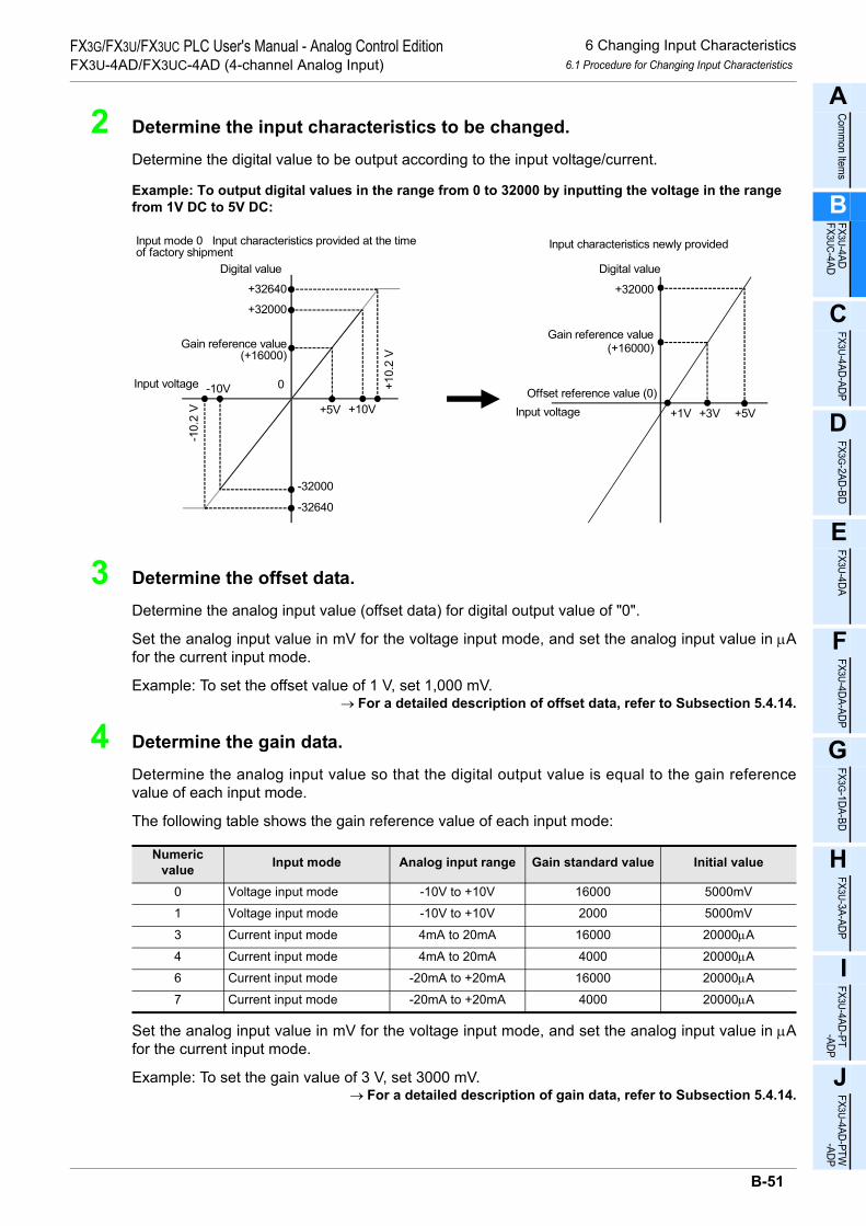
6 Changing Input Characteristics6.1 Procedure for Changing Input Characteristics
A
Comm
on Items
B
FX3U-4ADFX3UC-4AD
C
FX3U-4AD-ADP
D
FX3G-2AD-BD
E
FX3U-4DA
F
FX3U-4DA-ADP
G
FX3G-1DA-BD
H
FX3U-3A-ADP
I
FX3U-4AD-PT -ADP
J
FX3U-4AD-PTW -ADP
FX3G/FX3U/FX3UC PLC User's Manual - Analog Control EditionFX3U-4AD/FX3UC-4AD (4-channel Analog Input)
2 Determine the input characteristics to be changed.
Determine the digital value to be output according to the input voltage/current.
Example: To output digital values in the range from 0 to 32000 by inputting the voltage in the range from 1V DC to 5V DC:
3 Determine the offset data.
Determine the analog input value (offset data) for digital output value of "0".
Set the analog input value in mV for the voltage input mode, and set the analog input value in µAfor the current input mode.
Example: To set the offset value of 1 V, set 1,000 mV.→ For a detailed description of offset data, refer to Subsection 5.4.14.
4 Determine the gain data.
Determine the analog input value so that the digital output value is equal to the gain referencevalue of each input mode.
The following table shows the gain reference value of each input mode:
Set the analog input value in mV for the voltage input mode, and set the analog input value in µAfor the current input mode.
Example: To set the gain value of 3 V, set 3000 mV.→ For a detailed description of gain data, refer to Subsection 5.4.14.
Numeric value Input mode Analog input range Gain standard value Initial value
0 Voltage input mode -10V to +10V 16000 5000mV
1 Voltage input mode -10V to +10V 2000 5000mV
3 Current input mode 4mA to 20mA 16000 20000µA
4 Current input mode 4mA to 20mA 4000 20000µA
6 Current input mode -20mA to +20mA 16000 20000µA
7 Current input mode -20mA to +20mA 4000 20000µA
Digital value
Input voltage
+32000
+32640
-32640
-32000
-10V
+10V
0 +10.
2 V
-10.
2 V
Digital value
Input voltage +1V
(+16000)
+3V
Gain reference value
Offset reference value (0)
Input mode 0 Input characteristics provided at the timeof factory shipment
Input characteristics newly provided
+5V
Gain reference value(+16000)
+32000
+5V
B-51

6 Changing Input Characteristics6.1 Procedure for Changing Input Characteristics
FX3G/FX3U/FX3UC PLC User's Manual - Analog Control EditionFX3U-4AD/FX3UC-4AD (4-channel Analog Input)
5 Create a sequence program.
To change the input characteristics, write the offset data (BFM #41 to #44) and the gain data (BFM#51 to #54) in the sequence program, and then turn on the corresponding bit of BFM #21 for thecorresponding channel. The following example shows a program for the unit number 0.
Example: Program for changing the input characteristics of channels 1 and 2 (For FX3U, FX3UC SeriesPLCs):
*1. It takes approximately 5 seconds to change the input mode (BFM #0). This is because all the setvalues should be changed.After changing the input mode, be sure to wait for 5 seconds or more before setting other data.
The input characteristics of each channel can be written in BFM #21. It is also possible to performbatch writing of input characteristics for two or more channels.
6 Transfer the sequence program to change the input characteristics.
Transfer the sequence program, and start the PLC.
Start the PLC, and turn on the command (X000) to write the input characteristics. In approx. 5 sec-onds, the offset data and the gain data will be written.
Since the offset data and the gain data are stored in the 4AD EEPROM, it is possible to delete thesequence program.
7 Read out the analog data to check the data.
Create the following program to check the stored data (For FX3U, FX3UC Series PLCs):
→ If data is not stored properly, refer to Chapter 8 "Troubleshooting".
X000 FNC 12 MOV
HFF00 U0\G0P
SET M0M0
T0 FNC 16 FMOV
K1000 U0\G41 K2P
FNC 16 FMOV
K3000 U0\G51 K2P
FNC 12 MOV
H0003 U0\G21P
RST M0
Input mode specificationfor channels 1 to 4
Offset value ofchannels 1 and 2
Gain value ofchannels 1 and 2
Batch writing of offset and gainvalues of channels 1 and 2
Command for writing input characteristics
K50T0*1
M8000 FNC 16 BMOV
U0\G10 D0 K4
The digital values set forchannels 1 to 4 will be readout to D0 to D3.
RUN monitor
B-52

7 Examples of Practical Programs7.1 Program That Uses Averaging Time
A
Comm
on Items
B
FX3U-4ADFX3UC-4AD
C
FX3U-4AD-ADP
D
FX3G-2AD-BD
E
FX3U-4DA
F
FX3U-4DA-ADP
G
FX3G-1DA-BD
H
FX3U-3A-ADP
I
FX3U-4AD-PT -ADP
J
FX3U-4AD-PTW -ADP
FX3G/FX3U/FX3UC PLC User's Manual - Analog Control EditionFX3U-4AD/FX3UC-4AD (4-channel Analog Input)
7. Examples of Practical Programs
Use the functions incorporated in the 4AD to create practical programs. This chapter describes the examplesof practical programs.• Program that uses the averaging time• Program that uses convenient functions• Program that uses the data history function• Program that initializes 4AD (to the factory default status)
7.1 Program That Uses Averaging Time
This section describes a program that uses the analog data averaging time input to the 4AD or the digital filterfunction of the 4AD.
1. ConditionsThe sequence program described in this section is created under the following conditions.1) System configuration
The FX3U-4AD (unit No.0) should be connected to the FX3U Series PLC.2) Input mode
Channels 1 and 2 should be set to mode 0 (voltage input, -10V to +10V → -32000 to +32000).Channels 3 and 4 should be set to mode 3 (current input, 4mA to 20mA → 0 to 16000).
3) Averaging timeFor channels 1 to 4, the averaging time should be set to "10".
4) Digital filter functionFor channels 1 to 4, the digital filter function should be disabled (default).
5) Device assignment
2. Example of sequence program• For FX3U, FX3UC Series PLCs
*1. After setting the input mode, set the data writing time (waiting time) to 5 seconds or more for eachsetting.The specified input mode will be retained even if power failure occurs. After specifying the input mode,if the same input mode is used, it is not necessary to set the input mode and waiting time (T0 K50).
*2. To use the default value set for the digital filter function, it is not necessary to set the digital filterfunction in the sequence program.
Device DescriptionD0 A/D converted digital value for channel 1D1 A/D converted digital value for channel 2D2 A/D converted digital value for channel 3D3 A/D converted digital value for channel 4
M8002 FNC 12 MOV
H3300 U0\G0P
M8000K50T0
*1
T0 FNC 16 FMOV
K10 U0\G2 K4P
Input modes of channels 1to 4 will be specified.
For channels 1 and 2, the averaging timewill be set to "10".
Initial pulse
FNC 16 FMOV
K0 U0\G6 K4P
The digital filter function of channels 1and 2 will be disabled.
FNC 15 BMOV
U0\G10 D0 K4
RUN monitor
*2
The digital values set for channels1 to 4 will be read out to D0 to D3.
*1
B-53

7 Examples of Practical Programs7.1 Program That Uses Averaging Time
FX3G/FX3U/FX3UC PLC User's Manual - Analog Control EditionFX3U-4AD/FX3UC-4AD (4-channel Analog Input)
• For FX3G, FX3U, FX3UC Series PLCs
*1. After setting the input mode, set the data writing time (waiting time) to 5 seconds or more for eachsetting.The specified input mode will be retained even if power failure occurs. After specifying the input mode,if the same input mode is used, it is not necessary to set the input mode and waiting time (T0 K50).
*2. To use the default value set for the digital filter function, it is not necessary to set the digital filterfunction in the sequence program.
M8002
M8000K50T0
*1
T0
Input modes of channels 1to 4 will be specified.
For channels 1 and 2, the averaging timewill be set to "10".
Initial pulse
The digital filter function of channels 1and 2 will be disabled.
RUN monitor
*2
The digital values set for channels1 to 4 will be read out to D0 to D3.
*1 FNC 79 TO
K0 K1P
K0 H3300
FNC 79 TO
K2 K4P
K0 K10
FNC 79 TO
K6 K4P
K0 K0
FNC 78 FROM
K10 K4K0 D0
B-54

7 Examples of Practical Programs7.2 Program That Uses Convenient Functions
A
Comm
on Items
B
FX3U-4ADFX3UC-4AD
C
FX3U-4AD-ADP
D
FX3G-2AD-BD
E
FX3U-4DA
F
FX3U-4DA-ADP
G
FX3G-1DA-BD
H
FX3U-3A-ADP
I
FX3U-4AD-PT -ADP
J
FX3U-4AD-PTW -ADP
FX3G/FX3U/FX3UC PLC User's Manual - Analog Control EditionFX3U-4AD/FX3UC-4AD (4-channel Analog Input)
7.2 Program That Uses Convenient Functions
This section describes a program that uses the 4AD convenient functions (BFM #22).
1. ConditionsThe sequence program described in this section is created under the following conditions.1) System configuration
The FX3U-4AD (unit No.0) should be connected to the FX3U Series PLC.2) Input mode
Channels 1 and 2 should be set to mode 0 (voltage input, -10V to +10V → -32000 to +32000).Channels 3 and 4 should be set to mode 3 (current input, 4mA to 20mA → 0 to 16000).
3) Averaging timeFor all the channels, the averaging time should be set to "1" (default).(To use the default value, it is not necessary to set the averaging time in the sequence program.)
4) Digital filter functionFor all channels, the digital filter function should be disabled (default).(To use the default value, it is not necessary to set the digital filter function in the sequence program.)
5) Convenient functionsThe upper/lower limit detection function, upper/lower limit error status data automatic transfer function,over-scale status data automatic transfer function, and error status data automatic transfer functionshould be used.
6) Device assignment
Device Description
InputX000 Clearance of upper/lower limit error dataX001 Clearance of over-scale data
Output
Y000 Output of channel-1 lower limit error dataY001 Output of channel-1 upper limit error dataY002 Output of channel-2 lower limit error dataY003 Output of channel-2 upper limit error dataY004 Output of channel-3 lower limit error dataY005 Output of channel-3 upper limit error dataY006 Output of channel-4 lower limit error dataY007 Output of channel-4 upper limit error dataY010 Output of channel-1 over-scale (lower limit) dataY011 Output of channel-1 over-scale (upper limit) dataY012 Output of channel-2 over-scale (lower limit) dataY013 Output of channel-2 over-scale (upper limit) dataY014 Output of channel-3 over-scale (lower limit) dataY015 Output of channel-3 over-scale (upper limit) dataY016 Output of channel-4 over-scale (lower limit) dataY017 Output of channel-4 over-scale (upper limit) dataY20 Output of error detection signalY21 Output of setting error detection signalD0 A/D converted digital value of channel 1D1 A/D converted digital value of channel 2D2 A/D converted digital value of channel 3D3 A/D converted digital value of channel 4
D100 Upper/lower limit error status data automatic transfer-to data registerD101 Over-scale status data automatic transfer-to data registerD102 Error status data automatic transfer-to data register
B-55

7 Examples of Practical Programs7.2 Program That Uses Convenient Functions
FX3G/FX3U/FX3UC PLC User's Manual - Analog Control EditionFX3U-4AD/FX3UC-4AD (4-channel Analog Input)
2. Example of sequence program• For FX3U, FX3UC Series PLCs
*1. After setting the input mode, set the data writing time (waiting time) to 5 seconds or more for eachsetting.After this, if the same input mode is used, it is not necessary to set the input mode and waiting time(T0 K50) again.
*2. The set input mode, convenient functions, upper/lower limit error status data automatic transfer-todata register number, over-scale status data automatic transfer-to data register number, and errorstatus data automatic transfer-to data register number are retained in the 4AD EEPROM. For thisreason, even if the sequence program is deleted, the previously set functions will still be valid.
M8002 FNC 12 MOV
H3300 U0\G0P
M8000K50T0
*1
T0
Input modes of channels 1 to 4 will bespecified.
The convenient functions will be set.
Initial pulse
The upper/lower limit error status data automatictransfer-to data register will be set to D100.
FNC 15 BMOV
U0\G10 D0 K4
RUN monitor
Reads the digital values of channels 1 to 4 from BFM#10to #13 into D0 to D3.
FNC 12 MOV
H01A2 U0\G22P
FNC 12 MOV
K100 U0\G126P
FNC 12 MOV
K101 U0\G128P
FNC 12 MOV
K102 U0\G129P
The over-scale status data automatic transfer-to dataregister will be set to D101.
The error status data automatic transfer-to data registerwill be set to D102.
X000 FNC 12 MOV
H0003 U0\G99P
Clearance of upper/lowerlimit error data
Clearance of over-scaledataX001
FNC 12 MOV
K0 U0\G28P
Clearance of upper/lower limit error data
Clearance of over-scale data
M8000 FNC 12 MOV
D100 K2Y000 The upper/lower limit error status data of each channelwill be output to Y000 to Y007.
RUN monitor
FNC 12 MOV
D101 K2Y010 The over-scale status data of each channel will be outputto Y010 to Y017.
D102.0The error detection signal will be output to Y020.Y020
Error detection
D102.8Y021
Setting error detection
The setting error detection signal will be output to Y021.
*2
*2
*2
*2
*2
B-56

7 Examples of Practical Programs7.2 Program That Uses Convenient Functions
A
Comm
on Items
B
FX3U-4ADFX3UC-4AD
C
FX3U-4AD-ADP
D
FX3G-2AD-BD
E
FX3U-4DA
F
FX3U-4DA-ADP
G
FX3G-1DA-BD
H
FX3U-3A-ADP
I
FX3U-4AD-PT -ADP
J
FX3U-4AD-PTW -ADP
FX3G/FX3U/FX3UC PLC User's Manual - Analog Control EditionFX3U-4AD/FX3UC-4AD (4-channel Analog Input)
• For FX3G, FX3U, FX3UC Series PLCs
*1. After setting the input mode, set the data writing time (waiting time) to 5 seconds or more for eachsetting.After this, if the same input mode is used, it is not necessary to set the input mode and waiting time(T0 K50) again.
*2. The set input mode, convenient functions, upper/lower limit error status data automatic transfer-todata register number, over-scale status data automatic transfer-to data register number, and errorstatus data automatic transfer-to data register number are retained in the 4AD EEPROM. For thisreason, even if the sequence program is deleted, the previously set functions will still be valid.
M8002
M8000K50T0
*1
T0
Input modes of channels 1 to 4 will bespecified.
The convenient functions will be set.
Initial pulse
The upper/lower limit error status data automatictransfer-to data register will be set to D100.
RUN monitor
Reads the digital values of channels 1 to 4 fromBFM#10 to #13 into D0 to D3.
The over-scale status data automatic transfer-to dataregister will be set to D101.
The error status data automatic transfer-to data registerwill be set to D102.
X000
Clearance of upper/lower limit error data
Clearance of over-scaledataX001
Clearance of upper/lower limit error data
Clearance of over-scale data
M8000 FNC 12 MOV
D100 K2Y000The upper/lower limit error status data of each channelwill be output to Y000 to Y007.
RUN monitor
The over-scale status data of each channel will beoutput to Y010 to Y017.
M0The error detection signal will be output to Y020.Y020
Error detection
M8Y021
Setting error detection
The setting error detection signal will be output to Y021.
*2
*2
*2
*2
*2
FNC 79 TO
K0 K1P
K0 H3300
FNC 79 TO
K22 K1P
K0 H01A2
FNC 79 TO
K126 K1P
K0 K100
FNC 79 TO
K128 K1P
K0 K101
FNC 79 TO
K129 K1P
K0 K102
FNC 78 FROM
K10 K4P
K0 D0
FNC 79 TO
K99 K1P
K0 H0003
FNC 79 TO
K28 K1K0 K0
FNC 12 MOV
D102 K4M0
FNC 12 MOV
D101 K2Y010
B-57

7 Examples of Practical Programs7.3 Program That Uses Data History Function
FX3G/FX3U/FX3UC PLC User's Manual - Analog Control EditionFX3U-4AD/FX3UC-4AD (4-channel Analog Input)
7.3 Program That Uses Data History Function
This section describes a program that uses the data history function of the 4AD.
1. ConditionsThe sequence program described in this section is created under the following functions.1) System configuration
The FX3U-4AD (unit No.0) should be connected to the FX3U Series PLC.2) Input mode
Channels 1 and 2 should be set to mode 0 (voltage input, -10V to +10V → -32000 to +32000).Channels 3 and 4 should be set to mode 3 (current input, 4mA to 20mA → 0 to 16000).
3) Averaging timeFor all the channels, the averaging time should be set to "1" (default).(To use the default value, it is not necessary to set the averaging time in the sequence program.)
4) Digital filter functionFor all channels, the digital filter function should be disabled (default).(To use the default value, it is not necessary to set the digital filter function in the sequence program.)
5) Data history functionFor all channels, the data sampling time should be set to 100 ms.The sampling cycle should be 100 ms × 4 (number of selected channels) = 400 ms.For all channels, data will be sampled 100 times, and the sampled data will be stored as data history inthe data registers.
6) Device assignment
Device Description
InputX000 Clearance of data historyX001 Temporarily stoppage of data history
Data register
D0 A/D converted digital value of channel 1D1 A/D converted digital value of channel 2D2 A/D converted digital value of channel 3D3 A/D converted digital value of channel 4
D100 to D199 Channel-1 data history(100 data samples)D200 to D299 Channel-2 data history(100 data samples)D300 to D399 Channel-3 data history(100 data samples)D400 to D499 Channel-4 data history(100 data samples)
B-58

7 Examples of Practical Programs7.3 Program That Uses Data History Function
A
Comm
on Items
B
FX3U-4ADFX3UC-4AD
C
FX3U-4AD-ADP
D
FX3G-2AD-BD
E
FX3U-4DA
F
FX3U-4DA-ADP
G
FX3G-1DA-BD
H
FX3U-3A-ADP
I
FX3U-4AD-PT -ADP
J
FX3U-4AD-PTW -ADP
FX3G/FX3U/FX3UC PLC User's Manual - Analog Control EditionFX3U-4AD/FX3UC-4AD (4-channel Analog Input)
2. Example of sequence program• For FX3U, FX3UC Series PLCs
*1. After setting the input mode, set the data writing time (waiting time) to 5 seconds or more for eachsetting.After this, if the same input mode is used, it is not necessary to set the input mode and waiting time(T0 K50) again.
*2. The set input mode and the sampling time are retained in the 4AD EEPROM. Therefore, even if thesequence program is deleted, the previously set functions will still be valid.
*3. If a large amount of history data is read out, the scan time of the PLC will be become longer. If thescan time exceeds 200 ms, the CPU error indicator lamp will illuminate, and the PLC will stop.Insert WDT instruction (watchdog timer refresh) between BMOV instructions.
M8002 FNC 12 MOV
H3300 U0\G0P
M8000K50T0
*1
T0
Input modes of channels 1 to 4 will bespecified.
The sampling time will be set to 100 ms.
Initial pulse
FNC 15 BMOV
U0\G10 D0 K4
RUN monitor
The digital values set for channels 1to 4 will be read out to D0 to D3.
FNC 12 MOV
K100 U0\G198P
Data history of all the channels will beerased.
X000 FNC 12 MOV
H000F U0\G199P
Clear datahistory
*2
Data history of all the channels will betemporarily stopped.
X001 FNC 12 MOV
H0F00 U0\G199P
Temporarily stopdata history
Temporary stoppage of data history will becanceled for all the channels.
FNC 12 MOV
H0000 U0\G199P
Temporarily stopdata history
X001
T0 FNC 15 BMOV
U0\G200 D100 K100
FNC 15 BMOV
U0\G1900 D200 K100
FNC 07 WDT
FNC 07 WDT
FNC 15 BMOV
U0\G3600 D300 K100
FNC 15 BMOV
U0\G5300 D400 K100
FNC 07 WDT
FNC 07 WDT
Channel-1 history data (100 data samples)will be read out to D100 to D199.
Channel-2 history data (100 data samples)will be read out to D200 to D299.
Channel-3 history data (100 data samples)will be read out to D300 to D399.
Channel-4 history data (100 data samples)will be read out to D400 to D499.
The watchdog timer will be refreshed.*3
The watchdog timer will be refreshed.*3
The watchdog timer will be refreshed.*3
The watchdog timer will be refreshed.*3
*2
B-59

7 Examples of Practical Programs7.3 Program That Uses Data History Function
FX3G/FX3U/FX3UC PLC User's Manual - Analog Control EditionFX3U-4AD/FX3UC-4AD (4-channel Analog Input)
• For FX3G, FX3U, FX3UC Series PLCs
*1. After setting the input mode, set the data writing time (waiting time) to 5 seconds or more for eachsetting.After this, if the same input mode is used, it is not necessary to set the input mode and waiting time(T0 K50) again.
*2. The set input mode and the sampling time are retained in the 4AD EEPROM. Therefore, even if thesequence program is deleted, the previously set functions will still be valid.
*3. If a large amount of history data is read out, the scan time of the PLC will be become longer. If thescan time exceeds 200 ms, the CPU error indicator lamp will illuminate, and the PLC will stop.Insert WDT instruction (watchdog timer refresh) between BMOV instructions.
M8002
M8000K50T0
*1
T0
Input modes of channels 1 to 4 will bespecified.
The sampling time will be set to 100 ms.
Initial pulse
RUN monitor
The digital values set for channels 1to 4 will be read out to D0 to D3.
Data history of all the channels will beerased.
X000
Clear datahistory
*2
Data history of all the channels will betemporarily stopped.
X001
Temporarily stopdata history
Temporary stoppage of data history will becanceled for all the channels.
Temporarily stopdata history
X001
T0
FNC 07 WDT
FNC 07 WDT
FNC 07 WDT
FNC 07 WDT
Channel-1 history data (100 data samples)will be read out to D100 to D199.
Channel-2 history data (100 data samples)will be read out to D200 to D299.
Channel-3 history data (100 data samples)will be read out to D300 to D399.
Channel-4 history data (100 data samples)will be read out to D400 to D499.
The watchdog timer will be refreshed.*3
The watchdog timer will be refreshed.*3
The watchdog timer will be refreshed.*3
The watchdog timer will be refreshed.*3
*2 FNC 79 TO
K0 K1P
K0 H3300
FNC 78 FROM
K10 K4P
K0 D0
FNC 79 TO
K198 K1P
K0 K100
FNC 79 TO
K199 K1P
K0 H000F
FNC 79 TO
K199 K1P
H0F00
FNC 79 TO
K199 K1P
H0000
FNC 79 TO
K200 K100D100
FNC 79 TO
K1900 K100D200
FNC 79 TO
K3600 K100K0 D300
FNC 79 TO
K4300 K100K0 D400
K0
K0
K0
K0
B-60

7 Examples of Practical Programs7.4 Initialization Program for 4AD (Factory Default)
A
Comm
on Items
B
FX3U-4ADFX3UC-4AD
C
FX3U-4AD-ADP
D
FX3G-2AD-BD
E
FX3U-4DA
F
FX3U-4DA-ADP
G
FX3G-1DA-BD
H
FX3U-3A-ADP
I
FX3U-4AD-PT -ADP
J
FX3U-4AD-PTW -ADP
FX3G/FX3U/FX3UC PLC User's Manual - Analog Control EditionFX3U-4AD/FX3UC-4AD (4-channel Analog Input)
7.4 Initialization Program for 4AD (Factory Default)
Execution of the following program will reset the input mode (BFM #0), offset data (BFM #41 to #44), gaindata (BFM #51 to #54), etc. to the factory default status.
1. ConditionsThe sequence program described in this section runs under the following conditions.1) System configuration
The FX3U-4AD (unit No.0) should be connected to the FX3U Series PLC.2) Device assignment
2. Example of sequence program• For FX3U, FX3UC Series PLCs
• For FX3G, FX3U, FX3UC Series PLCs
3. Cautions• It takes approximately 5 seconds to complete initialization.
Do not write any data to the buffer memory in this time.• When initialization is complete, the value of BFM #20 will be reset to "K0".• Priority is given to the data change disable (BFM #19). To initialize, write K2080 to BFM #19.
Device DescriptionX000 4AD initialization command
X000 FNC 12 MOV
K1 U0\G20P
The 4AD will be initialized.(BFM #0 to #6999 will be cleared.)
4AD initialization command
X000The 4AD will be initialized.(BFM #0 to #6999 will be cleared.)
4AD initialization command
FNC 79 TO
K20 K1P
K0 K1
B-61

8 Troubleshooting8.1 PLC Version Number Check
FX3G/FX3U/FX3UC PLC User's Manual - Analog Control EditionFX3U-4AD/FX3UC-4AD (4-channel Analog Input)
8. Troubleshooting
This chapter describes troubleshooting methods and error codes.If the A/D conversion data is not input, or if the proper digital value is not input, check the following items:• PLC version number• Wiring• Program• Error status
8.1 PLC Version Number Check
Verify that the PLC being used is of the following version or later.
FX3U-4AD
FX3UC-4AD
→ For a detailed description of version number check method, refer to Section 1.3.
8.2 Wiring Check
Check the wiring as follows:
1. PowerThe 4AD needs driving power. Verify that the power supply line is properly connected. Also check that the 24V indicator lamp of the 4AD is on.
2. Analog input lineUse the 2-core twisted shielded cable for the analog input line. In addition, be sure to separate the analog input line from any other power lines or inductive lines.
3. Use of current input modeTo use the current input mode for a channel, be sure to short-circuit the line between the V+ terminal and the I+ terminal of the channel.Without short circuiting the terminals, it is impossible to obtain the correctly converted digital values.
→ For a detailed description of wiring, refer to Chapter 4.
8.3 Program Check
Check the program as follows:
1. Storage devicesCheck whether the device holding digital values contains any values written by other programs.
2. Setting of averaging time and digital filter functionCheck if the averaging time or the digital filter function is set for the same channel. It is not possible to set bothfunctions for the same channel.
Compatible PLC Version numberFX3U Series PLC Ver. 2.20 or later
FX3UC Series PLC Ver. 1.30 or laterFX3G Series PLC Ver. 1.00 or later
Compatible PLC Version numberFX3UC Series PLC Ver. 1.30 or later
B-62

8 Troubleshooting8.4 Error Status Check
A
Comm
on Items
B
FX3U-4ADFX3UC-4AD
C
FX3U-4AD-ADP
D
FX3G-2AD-BD
E
FX3U-4DA
F
FX3U-4DA-ADP
G
FX3G-1DA-BD
H
FX3U-3A-ADP
I
FX3U-4AD-PT -ADP
J
FX3U-4AD-PTW -ADP
FX3G/FX3U/FX3UC PLC User's Manual - Analog Control EditionFX3U-4AD/FX3UC-4AD (4-channel Analog Input)
8.4 Error Status Check
If an error occurs in the 4AD, the corresponding bit of BFM #29 (error status buffer memory) will turn on. Tosolve the problem, refer to the troubleshooting method described below:
1. Error detection (b0)1) Description of error
If any bits from b2 to b4 are turned on, this bit (b0) will turn on.
2. Power supply error (b2)1) Description of error
The 24 V power is not being supplied properly.2) Remedy
Check the wiring condition or the supplied voltage.
3. Hardware error (b3)1) Description of error
4AD may be defective.2) Remedy
Please contact the nearest Mitsubishi Electric distributor office.
4. A/D conversion error (b4)1) Description of error
The A/D conversion value is abnormal.2) Remedy
Check the over-scale status data (BFM #28) to localize the error channel. After that, check to make surethe input analog data is in the specified range.
5. BFM reading/writing impossible (b6)1) Description of error
While voltage input characteristics are being changed, this bit will turn on. If this bit (b6) is on, A/Dconversion data cannot be read out correctly or cannot be written to the BFM correctly.
2) RemedyCheck the sequence program and confirm that the input characteristics (BFM #21 b0 to b3) are not beingwritten continuously.
6. Data setting error detection (b8)1) Description of error
If any bits from b10 to b15 are turned on, this bit (b8) will turn on.
7. Averaging time setting error (b10)1) Description of error
The averaging time (BFM #2 to #5) is not set correctly.2) Remedy
Set the averaging time again in the range from 1 to 4095.
Bit No. Items Bit No. Itemsb0 Error detection b8 Data setting error detection
b1 - b9 -
b2 Power supply error b10 Averaging time setting error
b3 Hardware error b11 Digital filter setting error
b4 A/D conversion error b12 Abrupt change detection value setting error
b5 - b13 Upper/lower limit detection setting error
b6 BFM reading/writing impossible b14 -
b7 - b15 Addition data setting error
B-63

8 Troubleshooting8.5 4AD Initialization and Test Program
FX3G/FX3U/FX3UC PLC User's Manual - Analog Control EditionFX3U-4AD/FX3UC-4AD (4-channel Analog Input)
8. Digital filter setting error (b11)1) Description of error
The digital filter value (BFM #6 to #9) is not set correctly.2) Remedy
Set the digital filter value again in the range from 0 to 1600.Also check that the averaging is not set for the selected channel.
9. Abrupt change detection value setting error (b12)1) Description of error
The abrupt change detection value (BFM #91 to #94) is not set correctly.2) Remedy
Check that the abrupt change detection value is in the range specified for the selected input mode. If thevalue is out of the range, correct it.
10. Upper/lower limit detection setting error (b13)1) Description of error
The lower limit error detection value (BFM #71 to #74) or the upper limit error detection value (BFM #81 to#84) is not set correctly.
2) RemedyCheck that the upper/lower limit error detection value is in the range specified for the selected inputmode. If the value is out of the range, correct it.
11. Addition data setting error (b15)1) Description of error
The addition data (BFM #61 to #64) is not set correctly.2) Remedy
Set the addition data again in the range from -16000 to +16000.
8.5 4AD Initialization and Test Program
If the remedies above cannot solve the problem, initialize and then check the conditions of the 4AD using thetest program.
→ For a detailed description of 4AD initialization program, refer to Subsection 7.4.→ For a detailed description of the test program, refer to Chapter 4.
B-64

A
Comm
on Items
B
FX3U-4ADFX3UC-4AD
C
FX3U-4AD-ADP
D
FX3G-2AD-BD
E
FX3U-4DA
F
FX3U-4DA-ADP
G
FX3G-1DA-BD
H
FX3U-3A-ADP
I
FX3U-4AD-PT -ADP
J
FX3U-4AD-PTW -ADP
FX3G/FX3U/FX3UC PLC User's Manual - Analog Control EditionFX3U-4AD-ADP (4-channel analog Input)
FX3G/FX3U/FX3UC Series Programmable Controllers
User's Manual [Analog Control Edition] FX3U-4AD-ADP (4-channel analog Input)
Foreword
This manual describes the specifications, wiring, and operation methods for the FX3U-4AD-ADP special adapter (4-channel analog input) and should be read and understood before attempting to install or use the unit.Store this manual in a safe place so that you can take it out and read it whenever necessary. Always forward it to the end user.
© 2005 MITSUBISHI ELECTRIC CORPORATION
This manual confers no industrial property rights or any rights of any other kind, nor does it confer any patentlicenses. Mitsubishi Electric Corporation cannot be held responsible for any problems involving industrial propertyrights which may occur as a result of using the contents noted in this manual.
C-1

FX3G/FX3U/FX3UC PLC User's Manual - Analog Control EditionFX3U-4AD-ADP (4-channel analog Input)
C-2

1 Outline1.1 Outline of Functions
FX3G/FX3U/FX3UC PLC User's Manual - Analog Control EditionFX3U-4AD-ADP (4-channel analog Input)
A
Comm
on Items
B
FX3U-4ADFX3UC-4AD
C
FX3U-4AD-ADP
D
FX3G-2AD-BD
E
FX3U-4DA
F
FX3U-4DA-ADP
G
FX3G-1DA-BD
H
FX3U-3A-ADP
I
FX3U-4AD-PT -ADP
J
FX3U-4AD-PTW -ADP
1. Outline
This chapter outlines the FX3U-4AD-ADP (referred to as the 4AD-ADP).
1.1 Outline of Functions
The FX3U-4AD-ADP is an analog special adapter. Connect the FX3U-4AD-ADP to the FX3U/FX3UC/FX3GSeries PLC to read 4 channels of voltage/current data.1) Up to 4 4AD-ADP units can be connected to the FX3U/FX3UC Series PLC.
Up to 2*1 4AD-ADP units can be connected to the FX3G Series PLC. (including the other analog special adapters).
2) Either "voltage input" or "current input" can be specified for each channel.3) A/D conversion data of each channel will be automatically written to the special data register of the FX3U/
FX3UC/FX3G Series PLC.
4thadapter
Number of connectable
units
……For a detaileddescription of wiring,refer to Chapter 3.
……To check the connectablePLC model number, referto Section 1.3.
Point and section to bereferred to
System
……
Special devices …… For a detailed descriptionof special devices, refer toChapter 4.
For a detailed descriptionof a basic program, refer toSection 4.8.
Analog data
Refer to the system configuration shown in the User's Manual - Hardware Edition to check the number of connectable unitsand to configure the entire system.
Transfer directionContents
•Analog data
•Switching of input mode•Setting of averaging time
(including other analog special adapters)
3rdadapter
2ndadapter
1stadapter
1st adapter M/D8260 to M/D8269
M/D8270 to M/D8279
M/D8280 to M/D8289
M/D8290 to M/D8299
2nd adapter
3rd adapter
4th adapter
Flowmeter, pressure sensor, etc.
++
Expansion board*2
FX3U/FX3UC Series PLC
FX3U/FX3UC Series PLC : 4 maximum
FX3G Series PLC : 2 maximum*1
/FX3G
For FX3U/FX3UC
Series PLC
*1.Only 1 analog special adapter can be connected to the 14-point and 24-point type main unit.
*2.The expansion board is not required when connecting with the FX3UC (D, DSS) PLC.For the FX3G Series PLC a connector conversion adapter is used.
C-3

1 Outline1.2 Setup Procedure Before Starting Operation
FX3G/FX3U/FX3UC PLC User's Manual - Analog Control EditionFX3U-4AD-ADP (4-channel analog Input)
1.2 Setup Procedure Before Starting Operation
Before starting analog input using the 4AD-ADP, follow the procedure below to set up the system:
Specifications:
• Operation environment
• Performance specifications
• Input characteristics
Specifications check
Refer to Chapter 2.
System configuration and selection
Wiring
Refer to Chapter 3.
FX3U-4AD-ADP
System configuration:
(Refer to the common pages for analog control.)
• Selection of units
Refer to the
common pages.
Wiring:
• Selection of sensor cable
• Power supply line
• Analog input line
Outline of system:
• Compatible PLC version number
• Compatible programming tool version number
Outline
Refer to Chapter 1.
Programming
Refer to Chapter 4.
Programming:
• Details of special devices
• Examples of basic programs
Changing of input characteristics
Refer to Chapter 5.
Method of input characteristics change:
• Convenient function program• How to use scaling instruction
If the error status data or the input analog value is
abnormal, refer to Chapter 6 "Troubleshooting."
C-4

1 Outline1.3 Connectable PLCs and Version Number
FX3G/FX3U/FX3UC PLC User's Manual - Analog Control EditionFX3U-4AD-ADP (4-channel analog Input)
A
Comm
on Items
B
FX3U-4ADFX3UC-4AD
C
FX3U-4AD-ADP
D
FX3G-2AD-BD
E
FX3U-4DA
F
FX3U-4DA-ADP
G
FX3G-1DA-BD
H
FX3U-3A-ADP
I
FX3U-4AD-PT -ADP
J
FX3U-4AD-PTW -ADP
1.3 Connectable PLCs and Version Number
The 4AD-ADP is compatible with the following PLCs.
*1. The FX3U/FX3UC Series PLC Ver. 2.70 or later supports the under-scale detection.
1. Version checkSpecial data register D8001 contains information for determining the PLC version number.
→ For a detailed description of the version check, refer to A. Common Items Subsection 5.1.2.
2. How to check the manufacturer's serial numberThe year and month of production of the product can be checked on the nameplate, and on the front of theproduct.
→ For a detailed description of how to check the manufacturer's serial number,refer to A. Common Items Subsection 5.1.1.
1.4 Compatible Programming Tool Version Number
Use the programming tool with following version numbers to create programs for the 4AD-ADP:
1. GX Works2
2. GX Developer• FX3U/FX3UC Series PLC
• FX3G Series PLC
If a programming tool with the wrong version number is used, programming will not be possible.*2. For Ver. 8.13P to 8.24A of GX Developer, select FX3UC for the PLC type.
3. FX-30P
Compatible PLC Version number Date of productionFX3U Series PLC Ver.2.20 or later*1 After May 2005 (initial production)
FX3UC Series PLC Ver.1.20 or later*1 After April 2004
FX3G Series PLC Ver.1.00 or later After June 2008 (initial production)
Software Version number RemarksGX Works2SW DNC-GXW2-J Ver. 1.07H or later -
GX Works2SW DNC-GXW2-E Ver. 1.08J or later -
Software Version number RemarksGX DeveloperSW D5C-GPPW-J Ver. 8.13P or later
When selecting the model, select FX3U(C)*2.GX DeveloperSW D5C-GPPW-E Ver. 8.18U or later
Software Version number RemarksGX Developer• SW D5C-GPPW-J• SW D5C-GPPW-E
Ver. 8.72A or later -
Model name Version number RemarksFX-30P Ver.1.00 or later -
C-5

2 Specifications2.1 Generic Specifications
FX3G/FX3U/FX3UC PLC User's Manual - Analog Control EditionFX3U-4AD-ADP (4-channel analog Input)
2. Specifications
This chapter describes the general, power supply, and performance specifications for the 4AD-ADP.
2.1 Generic Specifications
*1. The criterion is shown in IEC61131-2.*2. If 4AD-ADP is connected to the FX3UC Series PLC, direct installation is not possible.*3.
→ For a detailed description of the grounding, refer to Section 3.5.*4. If the pressure is higher than the atmospheric pressure, do not use the 4AD-ADP.
The 4AD-ADP may malfunction.
Item SpecificationsAmbient temperature
0 to 55°C (32 to 131°F) when operating -25 to 75°C (-13 to 167°F) when stored
Relative humidity 5 to 95%RH (no condensation) when operating
Vibration resistance*1
Frequency(Hz)
Acceleration(m/s2)
Half amplitude(mm)
Tests 10 times in each direction (X-, Y-, and Z-axis directions) (Total: 80 min, each)
DIN Rail Mounting10 - 57 - 0.035
57 - 150 4.9 -
Direct Mounting*210 to 57 − 0.075
57 to 150 9.8 −
Shock resistance*1 147 m/s2 Acceleration, Action time: 11ms, 3 times by half-sine pulse in each direction X, Y, and Z
Noise resistance
Using noise simulator of:Noise voltage: 1,000Vp-p / Noise width: 1µs / Rise: 1ns / Cycle: 30 to 100Hz
Dielectric withstand voltage
500 V AC, for 1 minBetween all terminals and ground terminal
Insulation resistance
5MΩ or more using 500V DC insulation resistance meter
GroundingClass D grounding (grounding resistance: 100 Ω or less) <Common grounding with a heavy electrical system is not allowed.>*3
Workingenvironment Free from corrosive or flammable gas and excessive conductive dusts
Workingaltitude < 2000m*4
PLC OtherequipmentPLC Other
equipmentPLC Otherequipment
Shared groundingGood condition
Common groundingNot allowed
Independent groundingBest condition
C-6

2 Specifications2.2 Power Supply Specifications
FX3G/FX3U/FX3UC PLC User's Manual - Analog Control EditionFX3U-4AD-ADP (4-channel analog Input)
A
Comm
on Items
B
FX3U-4ADFX3UC-4AD
C
FX3U-4AD-ADP
D
FX3G-2AD-BD
E
FX3U-4DA
F
FX3U-4DA-ADP
G
FX3G-1DA-BD
H
FX3U-3A-ADP
I
FX3U-4AD-PT -ADP
J
FX3U-4AD-PTW -ADP
2.2 Power Supply Specifications
2.3 Performance Specifications
Item SpecificationsA/D conversion circuit driving power
24V DC +20%-15%, 40mA(It is necessary to connect a 24V DC power supply to the terminal block.)
Interface driving power5V DC, 15mA(Since the internal power is supplied from the FX Series main unit, it is notnecessary to supply the power.)
ItemSpecifications
Voltage input Current inputAnalog input range
0V to 10V DC(Input resistance: 194 kΩ)
4mA to 20mA DC(Input resistance: 250 Ω)
Absolute input maximum -0.5V, +15V -2mA, +30mA
Digital output 12 bits, binary 11 bits, binary
Resolution 2.5mV (10V/4000) 10µA (16mA/1600)
Total accuracy
• ±0.5% (±50mV) for 10V full scale(when ambient temperature is 25°C ± 5°C)
• ±1.0% (±100mV) for 10V full scale(when ambient temperature is 0°C to 55°C)
• ±0.5% (±80µA) for 16mA full scale(when ambient temperature is 25°C ± 5°C)
• ±1.0% (±160µA) for 16mA full scale(when ambient temperature is 0°C to 55°C)
A/D conversion time
• FX3U/ FX3UC Series PLC : 200 µs (The data will be updated at every scan time.)• FX3G Series PLC : 250 µs (The data will be updated at every scan time.)
→ For a detailed description of data update, refer to Section 2.4.
Inputcharacteristics
Insulation method• The photocoupler is used to insulate the analog input area from the PLC.• The DC/DC converter is used to insulate the power supply line from the analog input area.• Channels are not insulated from each other.
Number of I/O points occupied 0 point (This number is not related to the maximum number of input/output points of the PLC.)
0
4000
10V 10.2V
4080
Analog input
Dig
ital o
utpu
t
0
1600
20mA 20.4mA
1640
Analog input
Dig
ital o
utpu
t
4mA
C-7

2 Specifications2.4 A/D Conversion Time
FX3G/FX3U/FX3UC PLC User's Manual - Analog Control EditionFX3U-4AD-ADP (4-channel analog Input)
2.4 A/D Conversion Time
This section describes the A/D conversion time.
2.4.1 When connected to a FX3U, FX3UC PLC
1. A/D conversion and special data register update timingA/D conversion is performed at every scan time of the PLC.During execution of END instruction, the PLC performs A/D conversion, reads out the A/D converted data,and then writes the data in the special data registers.
2. A/D conversion during PLC STOPEven if the PLC is stopped, A/D conversion will be performed and the special data registers will be updated.
3. If two or more analog special adapters are connectedDuring execution of the END instruction, data will be read out from all the connected adapters (in the order of1st adapter → 2nd adapter... 4th adapter).
4. A/D conversion speed (data update time)During execution of END instruction, the A/D converted data of all 4 channels will be read out in 200µs, andthe data read out will be written to the special data registers.END instruction execution time will be "200µs × number of connected analog adapters."
FX3U/FX3UC Series PLCFX3U-4AD-ADP
1stFX3U-4AD-ADP
n'th
A/Dconversion
200µs/4ch
A/Dconversion
200µs/4ch
Digital value reading
A/D conversion startcommand
END instruction
Sequenceprogram
Digital value reading
A/D conversion startcommand
C-8

2 Specifications2.4 A/D Conversion Time
FX3G/FX3U/FX3UC PLC User's Manual - Analog Control EditionFX3U-4AD-ADP (4-channel analog Input)
A
Comm
on Items
B
FX3U-4ADFX3UC-4AD
C
FX3U-4AD-ADP
D
FX3G-2AD-BD
E
FX3U-4DA
F
FX3U-4DA-ADP
G
FX3G-1DA-BD
H
FX3U-3A-ADP
I
FX3U-4AD-PT -ADP
J
FX3U-4AD-PTW -ADP
2.4.2 When connected to a FX3G PLC
1. A/D conversion and special data register update timingA/D conversion is performed at every scan time of the PLC.During execution of END instruction, the PLC performs A/D conversion, reads out the A/D converted data,and then writes the data in the special data registers.
2. A/D conversion during PLC STOPEven if the PLC is stopped, A/D conversion will be performed and the special data registers will be updated.
3. If two analog special adapters are connectedDuring execution of the END instruction, data will be read out from all the connected adapters (in the order of1st adapter → 2nd adapter).
4. A/D conversion speed (data update time)During execution of END instruction, the A/D converted data of all 4 channels will be read out in 250µs, andthe data read out will be written to the special data registers.END instruction execution time will be "250µs × number of connected analog adapters."
FX3G Series PLCFX3U-4AD-ADP
1stFX3U-4AD-ADP
2nd
A/Dconversion
250µs/4ch
A/Dconversion
250µs/4ch
Digital value reading
A/D conversion startcommand
END instruction
Sequenceprogram
Digital value reading
A/D conversion startcommand
C-9
3 WiringFX3U/FX3UC Series PLC User's Manual - Analog Control EditionFX3U-4AD-ADP (4-channel analog Input)
3. Wiring
This chapter describes the 4AD-ADP wiring.Observe the following caution to wire the 4AD-ADP.
WIRING PRECAUTIONS
• Make sure to cut off all phases of the power supply externally before attempting wiring work.Failure to do so may cause electric shock or damages to the product.
WIRING PRECAUTIONS
• Connect the DC power supply wiring to the dedicated terminals described in this manual.If an AC power supply is connected to a DC input/output terminal or DC power supply terminal, the PLC will beburnt out.
• Do not wire vacant terminals externally.Doing so may damage the product.
• Perform class D grounding (grounding resistance: 100Ω or less) to the grounding terminal on the main unit.Do not use common grounding with heavy electrical systems.
• When drilling screw holes or wiring, make sure cutting or wire debris does not enter the ventilation slits.Failure to do so may cause fire, equipment failures or malfunctions.
• Make sure to observe the following precautions in order to prevent malfunctions under the influence of noise:- Do not bundle the power line or twisted shielded cable together with or lay it close to the main circuit, high-
voltage line, or load line.Otherwise, noise disturbance and/or surge induction are likely to take place. As a guideline, lay the control line at least 100mm (3.94") or more away from the main circuit, high-voltage line, or load line.
- Ground the shield of the analog input/output cable at one point on the signal receiving side. However, do not use common grounding with heavy electrical systems.
• Make sure to properly wire to the European terminal board in accordance with the following precautions.Failure to do so may cause electric shock, equipment failures, a short-circuit, wire breakage, malfunctions, ordamage to the product.- The disposal size of the cable end should follow the dimensions described in the manual.- Tightening torque should follow the specifications in the manual.- Twist the end of strand wire and make sure there are no loose wires. - Do not solder-plate the electric wire ends.- Do not connect more than the specified number of wires or electric wires of unspecified size.- Affix the electric wires so that neither the terminal block nor the connected parts are directly stressed.
C-10

3 Wiring3.1 Terminal Layout
FX3G/FX3U/FX3UC PLC User's Manual - Analog Control EditionFX3U-4AD-ADP (4-channel analog Input)
A
Comm
on Items
B
FX3U-4ADFX3UC-4AD
C
FX3U-4AD-ADP
D
FX3G-2AD-BD
E
FX3U-4DA
F
FX3U-4DA-ADP
G
FX3G-1DA-BD
H
FX3U-3A-ADP
I
FX3U-4AD-PT -ADP
J
FX3U-4AD-PTW -ADP
3.1 Terminal Layout
The terminals of the 4AD-ADP are arranged as follows:
Signal Application
External power
Channel 1 analog input
Channel 3 analog input
Channel 4 analog input
Channel 2 analog input
24+24-
I1+COM1V2+
I3+COM3V4+
COM4
V1+
I2+COM2V3+
I4+
Grounding terminal
24+
24-
VI+
I1+
CO
M1
V2+
I2+
CO
M2
V3+
I3+
CO
M3
V4+
I4+
CO
M4
FX3U-4AD-ADP
POWER
C-11

3 Wiring3.2 Applicable Cables and Terminal Tightening Torque
FX3G/FX3U/FX3UC PLC User's Manual - Analog Control EditionFX3U-4AD-ADP (4-channel analog Input)
3.2 Applicable Cables and Terminal Tightening Torque
Use the following cables to connect with the counterpart equipment. Terminate the cable ends as shown below.
1. Cables
Applicable cable and tightening torque
*1. Old model name : CRIMPFOX ZA 3*2. Old model name : CRIMPFOX UD 6
2. Termination of cable endTo terminate the cable, treat the stranded/single-wire directly or use a rod terminal with insulation sleeve.• To directly terminate the end of a stranded/single-wire cable:
- Twist the end of the stranded cable so that the "barbed wires" cannot protrude.
- Do not solder-plate the end of the cable.
• To terminate cable end using a rod terminal with insulation sleeve:If the cable cover is too thick, it may be difficult to insert the cable into the insulation sleeve. For this reason, select an appropriate cable while referring to the external view.<Reference>
*3. Old model name : CRIMPFOX ZA 3*4. Old model name : CRIMPFOX UD 6
3. Tool• To tighten terminals, use a small-sized screwdriver whose head is straight and is not widened as shown in
the figure to the right.
Note:If the diameter of screwdriver grip is too small, tightening torque will notbe able to be achieved. To achieve the appropriate tightening torqueshown in the table above, use the following screwdriver or anappropriate replacement (grip diameter: approximately 25mm (0.98")).<Reference>
Wire size (stranded/single-wire)
Tightening torque Termination
Single-wire 0.3mm2 to 0.5mm2
(AWG22 to 20)
0.22N•m to 0.25N•m
• To connect a stranded cable, peel the cover off the cableand then twist the core before connection.
• To connect a single-wire cable, just strip the cover off thecable before connection.2-wire 0.3mm2(AWG22)
Rod terminal withinsulation sleeve
0.3mm2 to 0.5mm2
(AWG22 to 20)(Refer to the rod terminalexternal view shown in thefollowing figure.)
• Rod terminal with insulation sleeve (recommended terminal)AI 0.5-8WH : Manufactured by Phoenix Contact
• Caulking toolCRIMPFOX 6*1 : Manufactured by Phoenix Contact(or CRIMPFOX 6T-F*2 : Manufactured by Phoenix Contact)
Manufacturer Model Caulking tool
Phoenix Contact AI 0.5-8WH CRIMPFOX 6*3
(or CRIMPFOX 6T-F*4)
Manufacturer ModelPhoenix Contact SZS 0.4×2.5
9mm
Termination of cable end
(0.35")
8mm (0.31")
Contact area(Crimp area)
14mm2.6mm(0.1")
Insulation sleeve
(0.55")
0.4mm 2.5mm
The headshould bestraight.
(0.01") (0.09")
C-12

3 Wiring3.3 Power Supply Line
FX3G/FX3U/FX3UC PLC User's Manual - Analog Control EditionFX3U-4AD-ADP (4-channel analog Input)
A
Comm
on Items
B
FX3U-4ADFX3UC-4AD
C
FX3U-4AD-ADP
D
FX3G-2AD-BD
E
FX3U-4DA
F
FX3U-4DA-ADP
G
FX3G-1DA-BD
H
FX3U-3A-ADP
I
FX3U-4AD-PT -ADP
J
FX3U-4AD-PTW -ADP
3.3 Power Supply Line
Connect the 24V DC power supply line of the 4AD-ADP to the 24+ and 24- terminals of the terminal block.
3.3.1 To connect to the FX3G, FX3U Series PLC
Caution regarding connection of the power supply line:
• Ground the " " terminal to a class-D grounded power supply line (100Ω or less) together with the grounding terminal of the PLC main unit.
• When using an external power supply, turn it ON at the same time with the main unit or earlier than the main unit. When turning OFF the power, confirm the safety of the system, and then turn OFF the power of the PLC (including special adapter) at the same time.
3.3.2 To connect to the FX3UC Series PLC
Cautions regarding connection of the power supply line:• For the 24V DC power supply line, be sure to use the same power as the FX3UC Series PLC.
• Ground the " " terminal to a class-D grounded power supply line (100Ω or less) together with the grounding terminal of the PLC main unit.
24V DCClass-D
grounding
Terminalblock
4AD-ADP
15V
24+24-
1. To use an External power supply
FX3G/FX3U Series
PLC (Main unit)
Class-Dgrounding
Terminalblock
4AD-ADP
15V
24+24- 24V0V
2. To use the 24V DC power of the PLC
FX3G/FX3U Series
PLC (Main unit)
24V DCClass-D
grounding
Terminalblock
4AD-ADP
GreenRedBlack
FX3UC Series PLC(Main unit)
Powerconnector
24+24- 24+24- 24+24-
Powerconnector
Powercrossoverconnector
RedBlack
FX2NC Series PLC(Input extension
block)15V
24+24-
C-13

3 Wiring3.4 Analog Input Line
FX3G/FX3U/FX3UC PLC User's Manual - Analog Control EditionFX3U-4AD-ADP (4-channel analog Input)
3.4 Analog Input Line
For analog input, "voltage input" or "current input" can be selected for each channel.
*1. Use the 2-core shielded twisted pair cable for the analog input lines, and separate the analog inputlines from other power lines or inductive lines.
*2. If "current input" is selected, be sure to short the line between the V + terminal and the I + terminal.( : Channel number).
3.5 Grounding
Grounding should be performed as stated below.• The grounding resistance should be 100Ω or less.• Independent grounding should be performed for best results.
When independent grounding is not performed, perform "shared grounding" as shown in the following figure.
→ For details, refer to the User’s Manual - Hardware Edition of the PLC Series.
• The grounding wire size should be AWG22 to 20 (0.3 to 0.5 mm2).• The grounding point should be close to the PLC, and all grounding wires should be as short as possible.
250Ω
147kΩ ch
47kΩ
4AD-ADP
V +, I +, ch : represents the channel number.
Terminalblock
I +COM
V +*1
I +COM
V + 250Ω147kΩ ch
47kΩ
Class-Dgrounding
24+24-
24V DC
+15V
*1
If current input is selected:
If voltage input is selected:
*2
Connection of externalpower supply line
PLC OtherequipmentPLC Other
equipmentPLC Otherequipment
Shared groundingGood condition
Common groundingNot allowed
Independent groundingBest condition
C-14

4 Programming4.1 Loading of A/D Conversion Data
FX3G/FX3U/FX3UC PLC User's Manual - Analog Control EditionFX3U-4AD-ADP (4-channel analog Input)
A
Comm
on Items
B
FX3U-4ADFX3UC-4AD
C
FX3U-4AD-ADP
D
FX3G-2AD-BD
E
FX3U-4DA
F
FX3U-4DA-ADP
G
FX3G-1DA-BD
H
FX3U-3A-ADP
I
FX3U-4AD-PT -ADP
J
FX3U-4AD-PTW -ADP
4. Programming
This chapter describes how to create programs that can read analog data using the 4AD-ADP.
4.1 Loading of A/D Conversion Data
1) The input analog data will be converted into digital data and then stored in the special devices of theFX3U/FX3UC/FX3G Series PLC.
2) If the data is stored in the special devices, the averaging time can be set, and the input mode can bespecified.
3) Special auxiliary relays (10 points) and special data registers (10 points) are assigned automaticallystarting from the adapter nearest to the main unit.
→ For a detailed description of special device assignment, refer to Section 4.2.• FX3U, FX3UC Series PLC
The analog special adapter nearest to the main unit is counted as the 1st analog special adapter, and the next adapter as the 2nd analog special adapter, and so on. However, in this case, do not include the high-speed input/output special adapter, communication special adapter, and the CF card special adapter.
Sequenceprogram
Special devices
A/D
A/D
A/D
A/D
Communic-ation
specialadapter
FX3U-4AD-ADP
FX3U-4AD-ADP
FX3U-4AD-ADP
FX3U-4AD-ADP FX3U/FX3UC Series PLC
1st2nd3rd4th
High-speedinput/output
specialadapter
Special auxiliary relays:M8280 to M8289
Special data registers:D8280 to D8289.
Special auxiliary relays:M8270 to M8279
Special data registers:D8270 to D8279
Special auxiliary relays:M8260 to M8269
Special data registers:D8260 to D8269
Special auxiliary relays:M8290 to M8299
Special data registers:D8290 to D8299
C-15
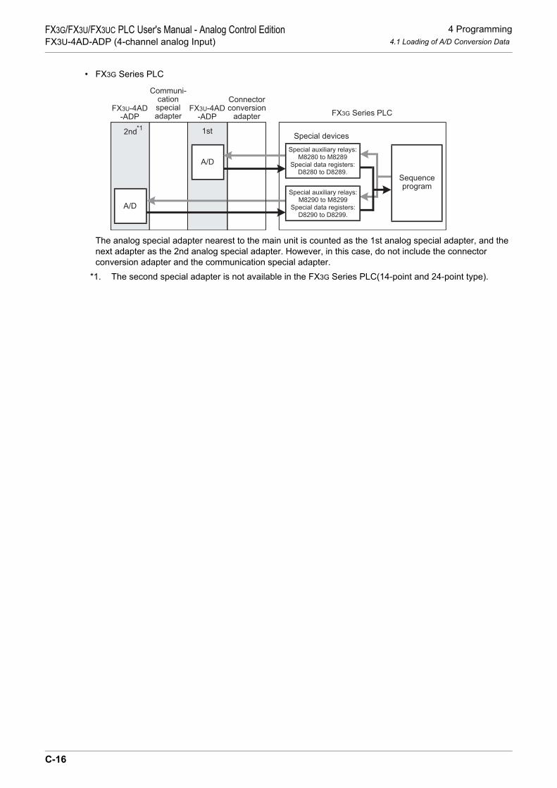
4 Programming4.1 Loading of A/D Conversion Data
FX3G/FX3U/FX3UC PLC User's Manual - Analog Control EditionFX3U-4AD-ADP (4-channel analog Input)
• FX3G Series PLC
The analog special adapter nearest to the main unit is counted as the 1st analog special adapter, and the next adapter as the 2nd analog special adapter. However, in this case, do not include the connector conversion adapter and the communication special adapter.
*1. The second special adapter is not available in the FX3G Series PLC(14-point and 24-point type).
Communi-cationspecialadapter
Connectorconversion
adapter
A/D
A/D
FX3U-4AD-ADP
FX3U-4AD-ADP
2nd*1 1st
FX3G Series PLC
Sequenceprogram
Special devices
Special auxiliary relays:M8280 to M8289
Special data registers:D8280 to D8289.
Special auxiliary relays:M8290 to M8299
Special data registers:D8290 to D8299.
C-16

4 Programming4.2 List of Special Devices
FX3G/FX3U/FX3UC PLC User's Manual - Analog Control EditionFX3U-4AD-ADP (4-channel analog Input)
A
Comm
on Items
B
FX3U-4ADFX3UC-4AD
C
FX3U-4AD-ADP
D
FX3G-2AD-BD
E
FX3U-4DA
F
FX3U-4DA-ADP
G
FX3G-1DA-BD
H
FX3U-3A-ADP
I
FX3U-4AD-PT -ADP
J
FX3U-4AD-PTW -ADP
4.2 List of Special Devices
If the 4AD-ADP is connected, special devices will be assigned automatically as shown in the following table:• FX3U, FX3UC Series PLC
R: Read / W: Write
Special device
Device numberDescription Attribute Refer-
ence1st 2nd 3rd 4th
Specialauxiliaryrelay
M8260 M8270 M8280 M8290 Switches the input mode of channel 1 R/W
Section 4.3
M8261 M8271 M8281 M8291 Switches the input mode of channel 2 R/WM8262 M8272 M8282 M8292 Switches the input mode of channel 3 R/WM8263 M8273 M8283 M8293 Switches the input mode of channel 4 R/W
M8264 to M8269
M8274 to M8279
M8284 to M8289
M8294 to M8299 Unused (Do not use.) - -
Specialdataregister
D8260 D8270 D8280 D8290 Channel-1 input data R
Section 4.4
D8261 D8271 D8281 D8291 Channel-2 input data RD8262 D8272 D8282 D8292 Channel-3 input data RD8263 D8273 D8283 D8293 Channel-4 input data R
D8264 D8274 D8284 D8294 Averaging time for channel-1 (Setting range: 1 to 4095) R/W
Section 4.5
D8265 D8275 D8285 D8295 Averaging time for channel-2 (Setting range: 1 to 4095) R/W
D8266 D8276 D8286 D8296 Averaging time for channel-3 (Setting range: 1 to 4095) R/W
D8267 D8277 D8287 D8297 Averaging time for channel-4 (Setting range: 1 to 4095) R/W
D8268 D8278 D8288 D8298 Error status R/W Section 4.6
D8269 D8279 D8289 D8299 Model code = 1 R Section 4.7
C-17

4 Programming4.3 Switching of Input Mode
FX3G/FX3U/FX3UC PLC User's Manual - Analog Control EditionFX3U-4AD-ADP (4-channel analog Input)
• FX3G Series PLCR: Read / W: Write
4.3 Switching of Input Mode
Turn the special auxiliary relay on/off to switch the input mode of 4AD-ADP between the current input modeand the voltage input mode.To switch the input mode, use the following special auxiliary relays:• FX3U, FX3UC Series PLC
• FX3G Series PLC
1. Program Example (For FX3U, FX3UC Series PLC)To switch the channel input mode, create a sequence program as follows:
Special deviceDevice number
Description Attribute Reference1st 2nd
Special auxiliary relay
M8280 M8290 Switches the input mode of channel 1 R/W
Section 4.3M8281 M8291 Switches the input mode of channel 2 R/WM8282 M8292 Switches the input mode of channel 3 R/WM8283 M8293 Switches the input mode of channel 4 R/W
M8284 to M8289
M8294 to M8299 Unused (Do not use.) - -
Special data register
D8280 D8290 Channel-1 input data R
Section 4.4D8281 D8291 Channel-2 input data RD8282 D8292 Channel-3 input data RD8283 D8293 Channel-4 input data R
D8284 D8294 Averaging time for channel-1 (Setting range: 1 to 4095) R/W
Section 4.5D8285 D8295 Averaging time for channel-2 (Setting
range: 1 to 4095) R/W
D8286 D8296 Averaging time for channel-3 (Setting range: 1 to 4095) R/W
D8287 D8297 Averaging time for channel-4 (Setting range: 1 to 4095) R/W
D8288 D8298 Error status R/W Section 4.6D8289 D8299 Model code = 1 R Section 4.7
Special auxiliary relayDescription
1st 2nd 3rd 4thM8260 M8270 M8280 M8290 Switches the input mode of channel 1
OFF: Voltage inputON: Current input
M8261 M8271 M8281 M8291 Switches the input mode of channel 2M8262 M8272 M8282 M8292 Switches the input mode of channel 3M8263 M8273 M8283 M8293 Switches the input mode of channel 4
Special auxiliary relayDescription
1st 2ndM8280 M8290 Switches the input mode of channel 1
OFF: Voltage inputON: Current input
M8281 M8291 Switches the input mode of channel 2M8282 M8292 Switches the input mode of channel 3M8283 M8293 Switches the input mode of channel 4
1) To switch the input mode of channel 1 of the 1st analog special adapter to the voltage input mode:
M8001M8260
Normally OFF
2) To switch the input mode of channel 2 of the 1st analog special adapter to the current input mode:
M8000M8261
Normally ON
C-18

4 Programming4.4 Input Data
FX3G/FX3U/FX3UC PLC User's Manual - Analog Control EditionFX3U-4AD-ADP (4-channel analog Input)
A
Comm
on Items
B
FX3U-4ADFX3UC-4AD
C
FX3U-4AD-ADP
D
FX3G-2AD-BD
E
FX3U-4DA
F
FX3U-4DA-ADP
G
FX3G-1DA-BD
H
FX3U-3A-ADP
I
FX3U-4AD-PT -ADP
J
FX3U-4AD-PTW -ADP
4.4 Input Data
Numeric data type: Decimal (K)The data converted by the 4AD-ADP will be stored in the special data registers.The special data registers that store the input data are shown in the following table:• FX3U, FX3UC Series PLC
• FX3G Series PLC
The converted A/D immediate data or averaged data (data average conforming to the specified averagingtime) will be stored in the above data registers as the input data.
→ For a detailed description of the averaging time, refer to Section 4.5.
1. Caution regarding input dataInput data is for reading only.Do not change (rewrite) the input data using sequence program, indicator, or device monitor of theprogramming tool.
2. Program Example (For FX3U, FX3UC Series PLC)
Even if the input data is not stored in D100 or D101, data registers D8260 or D8261 can be directly used inthe timer/counter set value or in a PID instruction.
Special data registerDescription
1st 2nd 3rd 4thD8260 D8270 D8280 D8290 Stores the channel-1 input data
D8261 D8271 D8281 D8291 Stores the channel-2 input data
D8262 D8272 D8282 D8292 Stores the channel-3 input data
D8263 D8273 D8283 D8293 Stores the channel-4 input data
Special data registerDescription
1st 2ndD8280 D8290 Stores the channel-1 input data
D8281 D8291 Stores the channel-2 input data
D8282 D8292 Stores the channel-3 input data
D8283 D8293 Stores the channel-4 input data
M8000
NormallyON
FNC 12MOV
D8260 D100
FNC 12MOV
D8261 D101
Stores the channel-1 input dataof the 1st analog specialadapter in the D100.
Stores the channel-2 input dataof the 1st analog specialadapter in the D101.
C-19

4 Programming4.5 Averaging Time
FX3G/FX3U/FX3UC PLC User's Manual - Analog Control EditionFX3U-4AD-ADP (4-channel analog Input)
4.5 Averaging Time
Setting range: 1 to 4095Initial value: K1
Numeric data type: Decimal (K)If the averaging time is set for the 4AD-ADP, the average data will be stored as the input data. The averagingtime can be set for each channel.Set the averaging time in the following special data registers:• FX3U, FX3UC Series PLC
• FX3G Series PLC
1. Cautions regarding averaging time setting• If the averaging time is set to "1", the immediate data is stored to the special data register.• If the averaging time is set in the range from 2 to 4095, the average value will be calculated to conform to
the set averaging time, and the average value obtained will be stored in the special data register.• After turning the PLC power on, the current data is stored to special data registers until the number of data
items reaches the set averaging time. After this, the average data will be stored.• Set the averaging time in the range from 1 to 4095. If the set value is outside the setting range, an error
signal will be output.• If the averaging time is set to "0" or smaller, the PLC will perform as if the averaging time is set to "1".
If the averaging time is set to "4096" or larger, the PLC will perform as if the averaging time is set to "4096".→ For a detailed description of the error status, refer to Section 6.5
2. Program Example (For FX3U, FX3UC Series PLC)
Special data registerDescription
1st 2nd 3rd 4thD8264 D8274 D8284 D8294 Averaging time for channel-1 data
D8265 D8275 D8285 D8295 Averaging time for channel-2 data
D8266 D8276 D8286 D8296 Averaging time for channel-3 data
D8267 D8277 D8287 D8297 Averaging time for channel-4 data
Special data registerDescription
1st 2ndD8284 D8294 Averaging time for channel-1 data
D8285 D8295 Averaging time for channel-2 data
D8286 D8296 Averaging time for channel-3 data
D8287 D8297 Averaging time for channel-4 data
M8000
NormallyON
FNC 12MOV
K1 D8264
FNC 12MOV
K5 D8265
Sets the averaging time forchannel-1 of the 1st analogspecial adapter to 1.
Sets the averaging time forchannel-2 of the 1st analogspecial adapter to 5.
C-20

4 Programming4.6 Error Status
FX3G/FX3U/FX3UC PLC User's Manual - Analog Control EditionFX3U-4AD-ADP (4-channel analog Input)
A
Comm
on Items
B
FX3U-4ADFX3UC-4AD
C
FX3U-4AD-ADP
D
FX3G-2AD-BD
E
FX3U-4DA
F
FX3U-4DA-ADP
G
FX3G-1DA-BD
H
FX3U-3A-ADP
I
FX3U-4AD-PT -ADP
J
FX3U-4AD-PTW -ADP
4.6 Error Status
If an error is detected in the 4AD-ADP, the error status data will be stored in the corresponding special dataregister.The following table shows the special data registers that store the error status data:• FX3U, FX3UC Series PLC
• FX3G Series PLC
Check the ON/OFF status of each bit of the error status data register to check the description of the error.Errors are assigned to the bits as shown in the following table. Create a program to detect errors.
→ For a detailed description of the error status, refer to Section 6.5.
*1. The FX3U/FX3UC Series PLC Ver.2.70 or later supports the under-scale detection function. The under-scale detection function is valid only for current input mode.
1. Caution regarding use of error status dataIf a 4AD-ADP hardware error (b6) or 4AD-ADP communication data error (b7) is detected, it is necessary toclear the error status with a program at the next power-on of the PLC.For this reason, be sure to create the following program:• For FX3G, FX3U, FX3UC Series PLC
*1. "1st" for the FX3G PLC.
Special data registerDescription
1st 2nd 3rd 4thD8268 D8278 D8288 D8298 Stores the error status data.
Special data registerDescription
1st 2ndD8288 D8298 Stores the error status data.
Bit Description Bit Descriptionb0 Channel-1 over-scale detection b7 4AD-ADP communication data error
b1 Channel-2 over-scale detection b8 Channel-1 under-scale detection*1
b2 Channel-3 over-scale detection b9 Channel-2 under-scale detection*1
b3 Channel-4 over-scale detection b10 Channel-3 under-scale detection*1
b4 EEPROM error b11 Channel-4 under-scale detection*1
b5 Averaging time setting error b12 to b15 Unused
b6 4AD-ADP hardware error(Power supply error included) - -
M8002Error status of 3rd analog special adapterb6 = OFF (hardware error)
Error status of 3rd analog status registerb7 = OFF (communication data error)
RST M6
RST M7
Initial pulse
MOV D8288 K4M0
M8000
Normally ON
MOV D8288K4M0
*1
*1
C-21

4 Programming4.6 Error Status
FX3G/FX3U/FX3UC PLC User's Manual - Analog Control EditionFX3U-4AD-ADP (4-channel analog Input)
• For FX3U, FX3UC Series PLC
2. Program Example 1 (For FX3G, FX3U, FX3UC Series PLC)
*1. "1st" for the FX3G PLC.
3. Program Example 2 (For FX3U, FX3UC Series PLC)
M8002 Error status of 1st analog special adapterb6 = OFF (hardware error)
Error status of 1st analog status registerb7 = OFF (communication data error)
RST D8268.6
RST D8268.7
Initial pulse
Y000M0
M8000
M1
M2
M3
M4
M5
M6
M7
Y001
Y002
Y003
Y004
Y005
Y006
Y007
Detects over-scale in channel 1 of
the 3rd adapter.
Detects over-scale in channel 2 of
Detects over-scale in channel 3 of
Detects over-scale in channel 4 of
EEPROM error in 3rd adapter
Averaging time setting error in
3rd adapter
4AD-ADP hardware error in
3rd adapter
4AD-ADP communication data
error in 3rd adapter
MOV D8288 K4M0
*1
*1
*1
*1
*1
the 3rd adapter.*1
the 3rd adapter.*1
the 3rd adapter.*1
Y000D8268.0
Y001D8268.1
Y002D8268.2
Y003D8268.3
Y004D8268.4
Y005D8268.5
Y006D8268.6
Y007D8268.7
Detects over-scale in channel 1 ofthe 1st adapter.
Detects over-scale in channel 2 ofthe 1st adapter.
Detects over-scale in channel 3 ofthe 1st adapter.
Detects over-scale in channel 4 ofthe 1st adapter.
EEPROM error in 1st adapter
Averaging time setting error in1st adapter
4AD-ADP hardware error in 1st adapter
4AD-ADP communication data error
in 1st adapter
C-22

4 Programming4.7 Model Code
FX3G/FX3U/FX3UC PLC User's Manual - Analog Control EditionFX3U-4AD-ADP (4-channel analog Input)
A
Comm
on Items
B
FX3U-4ADFX3UC-4AD
C
FX3U-4AD-ADP
D
FX3G-2AD-BD
E
FX3U-4DA
F
FX3U-4DA-ADP
G
FX3G-1DA-BD
H
FX3U-3A-ADP
I
FX3U-4AD-PT -ADP
J
FX3U-4AD-PTW -ADP
4.7 Model Code
Initial value: K1Numeric data type: Decimal (K)
When the 4AD-ADP is connected, model code "1" is stored in the corresponding special data register.The following table shows the special data registers that store the model code:• FX3U, FX3UC Series PLC
• FX3G Series PLC
Use the special data registers above to check whether a 4AD-ADP is connected or not.
1. Program Example (For FX3U, FX3UC Series PLC)
Special data registerDescription
1st 2nd 3rd 4thD8269 D8279 D8289 D8299 Model code
Special data registerDescription
1st 2ndD8289 D8299 Model code
Checks the model code of the 1stanalog special adapter
FNC224LD =
D8269 K1 Y007
C-23

4 Programming4.8 Basic Program Example
FX3G/FX3U/FX3UC PLC User's Manual - Analog Control EditionFX3U-4AD-ADP (4-channel analog Input)
4.8 Basic Program Example
Create the following basic program example to read out analog conversion (A/D conversion) data.• For FX3G, FX3U, FX3UC Series PLCThe following program will set channel 1 of the 3rd*1 adapter to voltage input mode and channel 2 to currentinput mode, and will store the converted A/D value of channel-1 data into D100 and that of channel-2 datainto D101.
Even if the input data is not stored into D100 or D101, the data registers D8280 or D8281 can be directly usedin the timer/counter setting value or in a PID instruction.
*1. "1st" for the FX3G PLC.
M8001M8280
M8000
M8000
M8281
Sets the input mode of channel1 to the voltage input mode(0 V to 10 V).
Sets the input mode of channel2 to the current input mode(4 mA to 20 mA).
M8002
Initial
pulse
RST M6
RST M7
Error status: b6 = OFF
Error status: b7 = OFF
M8000FNC 12
MOVK5 D8284
FNC 12MOV
K5 D8285
Sets the averaging time to "5"for channel-1 data.
Sets the averaging time to "5"for channel-2 data.
M8000FNC 12
MOVD8280 D100
FNC 12MOV
D8281 D101
Stores the A/D convertedchannel-1 digital data into D100.
Stores the A/D convertedchannel-2 digital data into D101.
MOV D8288 K4M0
MOV D8288K4M0
C-24

4 Programming4.8 Basic Program Example
FX3G/FX3U/FX3UC PLC User's Manual - Analog Control EditionFX3U-4AD-ADP (4-channel analog Input)
A
Comm
on Items
B
FX3U-4ADFX3UC-4AD
C
FX3U-4AD-ADP
D
FX3G-2AD-BD
E
FX3U-4DA
F
FX3U-4DA-ADP
G
FX3G-1DA-BD
H
FX3U-3A-ADP
I
FX3U-4AD-PT -ADP
J
FX3U-4AD-PTW -ADP
• For FX3U, FX3UC Series PLCThe following program will set channel 1 of the 1st adapter to voltage input mode and channel 2 to currentinput mode, and will store the converted A/D value of channel-1 data into D100 and that of channel-2 datainto D101.
Even if the input data is not stored into D100 or D101, the data registers D8260 or D8261 can be directly usedin the timer/counter setting value or in a PID instruction.
M8001M8260
M8000M8261
Sets the input mode of channel1 to the voltage input mode(0 V to 10 V).Sets the input mode of channel2 to the current input mode(4 mA to 20 mA).
M8002RST D8268.6
RST D8268.7
Error status: b6 = OFF
Error status: b7 = OFF
M8000FNC 12
MOVK5 D8264
FNC 12MOV
K5 D8265
Sets the averaging time to "5"for channel-1 data.
Sets the averaging time to "5"for channel-2 data.
M8000FNC 12
MOVD8260 D100
FNC 12MOV
D8261 D101
Stores the A/D convertedchannel-1 digital data into D100.
Stores the A/D convertedchannel-2 digital data into D101.
C-25

5 Changing of Input Characteristics5.1 Example: Changing of Voltage Input Characteristics
FX3G/FX3U/FX3UC PLC User's Manual - Analog Control EditionFX3U-4AD-ADP (4-channel analog Input)
5. Changing of Input Characteristics
Use the scaling instruction (SCL/FNC 259) for the FX3U/FX3UC Series PLC to change the input characteristics. FX3G Series PLCs do not support the scaling instruction. Use sequence programs to change the input characteristics.→ For a detailed description of scaling instruction, refer to the FX3G/FX3U/FX3UC Series Programming
Manual - Basic & Applied Instruction Edition.
5.1 Example: Changing of Voltage Input Characteristics
In the example explained in this section, the voltage input data "1 to 5 V" (Digital output value: 400 to 2000) ischanged to the digital output value "0 to 10000".
1. Input characteristics
0
4000
10VAnalog input
400
2000
5V1V 0
10000
Digital value actually obtainedby A/D conversion
2000(5V)400(1V)
Dig
ital outp
ut
tobe c
alc
ula
ted
(D110)
Voltage input characteristics(product specifications)
Digital output value to be changed
X-axis
Y-axis
Dig
ita
l o
utp
ut
C-26

5 Changing of Input Characteristics5.1 Example: Changing of Voltage Input Characteristics
FX3G/FX3U/FX3UC PLC User's Manual - Analog Control EditionFX3U-4AD-ADP (4-channel analog Input)
A
Comm
on Items
B
FX3U-4ADFX3UC-4AD
C
FX3U-4AD-ADP
D
FX3G-2AD-BD
E
FX3U-4DA
F
FX3U-4DA-ADP
G
FX3G-1DA-BD
H
FX3U-3A-ADP
I
FX3U-4AD-PT -ADP
J
FX3U-4AD-PTW -ADP
2. Example of program 1 (For FX3U, FX3UC Series PLC)• For example, create the following program to change the digital input data of the 1st analog special
adapter:M8001
M8260 Sets the input mode of channel 1 to the voltage input mode(0 V to 10 V)
M8002RST D8268.6
RST D8268.7
Error status: b6 = OFF
Error status: b7 = OFF
M8000FNC 12
MOVK1 D8264 Sets the averaging time to "1" for the channel-1 data
M8002 FNC 12MOV
K2 D50
FNC 12MOV
K400 D51
FNC 12MOV
K0 D52
FNC 12MOV
K2000 D53
FNC 12MOV
K10000 D54
M8000
Program for setting scaling instruction data table
The scaling instruction operation results will be stored in D100.
ItemNumber of points
Startpoint
X-coordinate
Y-coordinate
Endpoint
X-coordinate
Y-coordinate
DescriptionSets the number of pointsA/D converted digital valuestart point dataDigital output value of changedX-axis value start point
2Value Device
D50
400 D51
0 D52
A/D converted digital value endpoint dataDigital output value of changedX-axis value end point
2000 D53
10000 D54
FNC 259SCL
D8260 D50 D100
C-27

5 Changing of Input Characteristics5.1 Example: Changing of Voltage Input Characteristics
FX3G/FX3U/FX3UC PLC User's Manual - Analog Control EditionFX3U-4AD-ADP (4-channel analog Input)
3. Example of program 2 (For FX3G Series PLC)• For example, create the following program to change the digital input data (D110) of the 1st analog special
adapter:
4. Cautions regarding programming• GX Developer version 8.13P or later supports scaling instruction (SCL/FNC 259).• If the A/D converted digital value is out of the data table range specified by the scaling instruction (SCL/
FNC 259), the FX Series PLC will detect an operation error (error code: K6706).
D110 K400 D111FNC 21
SUB
M8002RST M6
RST M7
Error status: b6 = OFF
Error status: b7 = OFF
M8000K1 D8284
Sets the averaging scaling to "1"
for the channel-1 data.
Check to make sure the digital
value (D110) is in range.
Calculation for changing input
characteristics.
Stores the operation result in D100.
M8000D8280 D110
M8000 FNC 12MOV
D8288 K4M0
M8001M8280 Sets the input mode of channel 1 to the
voltage input mode
(0V to 10V).
D111 K10000 D112FNC 22
MUL
D112 K1600 D100FNC 23
DDIV
K4M0 D8288
M10
M10FNC 230LD>=
D110 K400 FNC 237AND<=
D110 K2000
FNC 12MOV
FNC 12MOV
FNC 12MOV
C-28

6 Troubleshooting6.1 PLC Version Number Check
FX3G/FX3U/FX3UC PLC User's Manual - Analog Control EditionFX3U-4AD-ADP (4-channel analog Input)
A
Comm
on Items
B
FX3U-4ADFX3UC-4AD
C
FX3U-4AD-ADP
D
FX3G-2AD-BD
E
FX3U-4DA
F
FX3U-4DA-ADP
G
FX3G-1DA-BD
H
FX3U-3A-ADP
I
FX3U-4AD-PT -ADP
J
FX3U-4AD-PTW -ADP
6. Troubleshooting
This chapter describes troubleshooting methods and error statuses.If the A/D conversion data is not input, or if the proper digital value is not input, check the following items:• PLC version number• Wiring• Special devices• Programs• Error status
6.1 PLC Version Number Check
• Any versions (from Ver.2.20 (initial version) to the latest version) of the FX3U Series are compatible.• Check the version number of the FX3UC Series PLC. The version number should be 1.20 or later.• Any versions (from Ver.1.00 (initial version) to the latest version) of the FX3G Series are compatible.
→ For a detailed description of the version number check method, refer to Section 1.3.
6.2 Wiring Check
Check the following items for wiring:
1. PowerThe 4AD-ADP needs driving power. Verify that the power supply line is properly connected. Also check thatthe POWER indicator lamp of the 4AD-ADP is on.
2. Analog input lineUse 2-core twisted shielded pair cable for the analog input line. In addition, be sure to separate the analoginput line from other power lines or inductive lines.
3. Use of current input modeTo use the current input mode for a channel, be sure to shortcircuit the line between the V + terminal and theI + terminal ( : channel number) of the channel. If the line is not shortcircuited, data will not be convertedinto proper digital data.
→ For a detailed description of wiring, refer to Chapter 3.
C-29

6 Troubleshooting6.3 Special Device Check
FX3G/FX3U/FX3UC PLC User's Manual - Analog Control EditionFX3U-4AD-ADP (4-channel analog Input)
6.3 Special Device Check
Check whether the special devices for the 4AD-ADP are being used correctly:
1. Input mode switchingCheck that the special device for switching the input mode is set correctly.Turn off the device to set the input mode to the voltage input mode. Turn on the device to set the input modeto the current input mode.
2. Input dataVerify that the special device of the selected channel is correctly selected. This special device should beselected depending on the connecting position and the channel.
3. Averaging timeCheck that the set averaging time is within the specified range. The averaging time should be set in the rangefrom 1 to 4095. If the set averaging time is outside the specified range, an error occurs.
4. Error statusCheck that no error is detected in the 4AD-ADP.If an error is detected, check the details of the error, and then check the wiring and programs.
→ For a detailed description of special devices, refer to Chapter 4.
6.4 Program Check
Check the following items for the program:
1. Clearing of error status at power onWhen the power is turned off and then on again, the error status should be cleared (b6 and b7 should turn off)using the program.
2. Check of storage devicesVerify that different values are not being stored in the same device by other parts of the program.
C-30

6 Troubleshooting6.5 Error Status Check
FX3G/FX3U/FX3UC PLC User's Manual - Analog Control EditionFX3U-4AD-ADP (4-channel analog Input)
A
Comm
on Items
B
FX3U-4ADFX3UC-4AD
C
FX3U-4AD-ADP
D
FX3G-2AD-BD
E
FX3U-4DA
F
FX3U-4DA-ADP
G
FX3G-1DA-BD
H
FX3U-3A-ADP
I
FX3U-4AD-PT -ADP
J
FX3U-4AD-PTW -ADP
6.5 Error Status Check
If an error occurs in the 4AD-ADP, the corresponding bit will turn ON.The bit which is turned ON due to the error status is held ON until overwritten to OFF by the program or thepower is cycled. If b6 or b7 is turned ON, then it is necessary to clear the error status using the program thenext time the power of the PLC is cycled.
*1. The FX3U/FX3UC Series PLC Ver.2.70 or later supports the under-scale detection function. The under-scale detection function is valid only for current input mode.
To solve the problem, refer to the troubleshooting method described below:
1. Over-scale detection (b0 to b3)1) Description of error
The input analog value (voltage or current value) is outside the specified range.Voltage input mode : The input voltage value is over the specified upper limit of 10.2 V.Current input mode : The input current value is over the specified upper limit of 20.4 mA.
2) RemedyCheck that the input analog value is within the specified range. Also check the wiring.
2. EEPROM error (b4)1) Description of error
The adjustment data which was set in the EEPROM before delivery from our factory cannot be read outproperly or has been destroyed.
2) RemedyPlease contact the nearest Mitsubishi Electric distributor office.
3. Averaging time setting error (b5)1) Description of error
The averaging time set for one of the channels (channels 1 to 4) is outside the specified range: 1 to 4095.2) Remedy
Check that the averaging time is set correctly for each channel.
4. 4AD-ADP hardware error (b6)1) Description of error
The 4AD-ADP is not operating properly.2) Remedy
Check that the 24V DC power is properly supplied to the 4AD-ADP. Also check that the 4AD-ADP iscorrectly connected to the PLC.If the problem cannot be solved even after the above check, please contact the nearest MitsubishiElectric distributor office.
Bit Description Bit Descriptionb0 Channel-1 over-scale detection b7 4AD-ADP communication data error
b1 Channel-2 over-scale detection b8 Channel-1 under-scale detection*1
b2 Channel-3 over-scale detection b9 Channel-2 under-scale detection*1
b3 Channel-4 over-scale detection b10 Channel-3 under-scale detection*1
b4 EEPROM error b11 Channel-4 under-scale detection*1
b5 Averaging time setting error b12 to b15 Unused
b6 4AD-ADP hardware error(Power supply error included) - -
C-31

6 Troubleshooting6.5 Error Status Check
FX3G/FX3U/FX3UC PLC User's Manual - Analog Control EditionFX3U-4AD-ADP (4-channel analog Input)
5. 4AD-ADP communication error (b7)1) Description of error
A communication error is detected between the 4AD-ADP and the PLC.2) Remedy
Check that the 4AD-ADP is correctly connected to the PLC.If the problem cannot be solved even after the above check, please contact the nearest MitsubishiElectric distributor office.
6. Under-scale detection (b8 to b11)1) Description of error
The input analog value (current value) is below the specified lower limit.This error is only detected for the current input mode, and indicates the input current is less than 2 mA.
2) RemedyCheck that the input analog value is within the specified range. Also check the wiring.
C-32

A
Comm
on Items
B
FX3U-4ADFX3UC-4AD
C
FX3U-4AD-ADP
D
FX3G-2AD-BD
E
FX3U-4DA
F
FX3U-4DA-ADP
G
FX3G-1DA-BD
H
FX3U-3A-ADP
I
FX3U-4AD-PT -ADP
J
FX3U-4AD-PTW -ADP
FX3G/FX3U/FX3UC PLC User's Manual - Analog Control EditionFX3G-2AD-BD (2-channel analog Input)
FX3G/FX3U/FX3UC Series Programmable Controllers
User's Manual [Analog Control Edition] FX3G-2AD-BD (2-channel analog Input)
Foreword
This manual describes the specifications, wiring, and operation methods for the FX3G-2AD-BD analog input expansion board (2-channel analog input) and should be read and understood before attempting to install or use the unit.Store this manual in a safe place so that you can take it out and read it whenever necessary. Always forward it to the end user.
© 2005 MITSUBISHI ELECTRIC CORPORATION
This manual confers no industrial property rights or any rights of any other kind, nor does it confer any patentlicenses. Mitsubishi Electric Corporation cannot be held responsible for any problems involving industrial propertyrights which may occur as a result of using the contents noted in this manual.
D-1

FX3G/FX3U/FX3UC PLC User's Manual - Analog Control EditionFX3G-2AD-BD (2-channel analog Input)
D-2

1 Outline1.1 Outline of Functions
FX3G/FX3U/FX3UC PLC User's Manual - Analog Control EditionFX3G-2AD-BD (2-channel analog Input)
A
Comm
on Items
B
FX3U-4ADFX3UC-4AD
C
FX3U-4AD-ADP
D
FX3G-2AD-BD
E
FX3U-4DA
F
FX3U-4DA-ADP
G
FX3G-1DA-BD
H
FX3U-3A-ADP
I
FX3U-4AD-PT -ADP
J
FX3U-4AD-PTW -ADP
1. Outline
This chapter outlines the FX3G-2AD-BD (referred to as the 2AD-BD).
1.1 Outline of Functions
The FX3G-2AD-BD is an analog expansion board. Connect the FX3G-2AD-BD to the FX3G Series PLC to read2 channels of voltage/current data.
1) Up to 2*1 2AD-BD units can be connected to the FX3G Series PLC. (including the other analog expansion board, analog special adapters).
2) Either "voltage input" or "current input" can be specified for each channel.3) A/D conversion data of each channel will be automatically written to the special data register of the FX3G
Series PLC.
Number of connectable
units
……For a detaileddescription of wiring,refer to Chapter 3.
……To check the connectablePLC model number, referto Section 1.3.
Point and section to bereferred to
System
……
Special devices …… For a detailed descriptionof special devices, refer toChapter 4.
For a detailed descriptionof a basic program, refer toSection 4.8.
Analog data
Refer to the system configuration shown in the User's Manual - Hardware Edition to check the number of connectable unitsand to configure the entire system.
Transfer direction
Contents
•Analog data
•Switching of input mode•Setting of averaging time
Board ABoard B
Board A M/D8260 to M/D8269
M/D8270 to M/D8279Board B
Connected to the option connector 2
including other analog expansion boards,
analog special adapters.
Connected to the option connector 1
Flowmeter, pressure sensor, etc.
For FX3G Series PLC
*1.Only 1 analog board can be connected to the FX3G Series PLC(14-point and 24-point type).
FX3G Series PLC
2*1 maximum
(
(
D-3
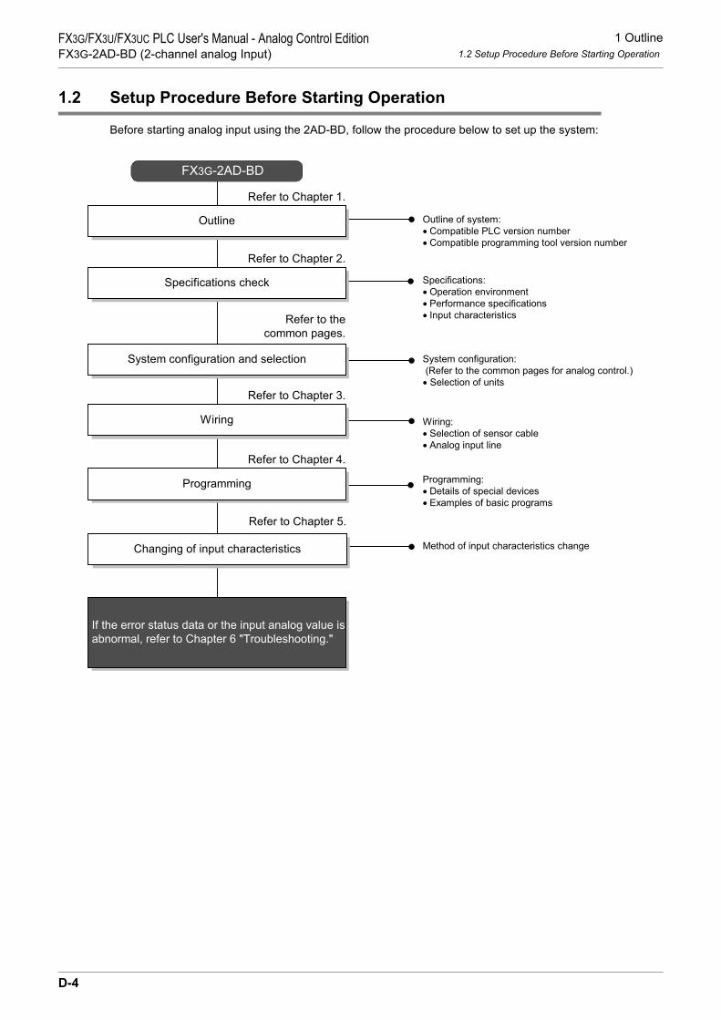
1 Outline1.2 Setup Procedure Before Starting Operation
FX3G/FX3U/FX3UC PLC User's Manual - Analog Control EditionFX3G-2AD-BD (2-channel analog Input)
1.2 Setup Procedure Before Starting Operation
Before starting analog input using the 2AD-BD, follow the procedure below to set up the system:
Specifications:
• Operation environment
• Performance specifications
• Input characteristics
Specifications check
Refer to Chapter 2.
System configuration and selection
Wiring
Refer to Chapter 3.
FX3G-2AD-BD
System configuration:
(Refer to the common pages for analog control.)
• Selection of units
Refer to the
common pages.
Wiring:
• Selection of sensor cable
• Analog input line
Outline of system:
• Compatible PLC version number
• Compatible programming tool version number
Outline
Refer to Chapter 1.
Programming
Refer to Chapter 4.
Programming:
• Details of special devices
• Examples of basic programs
Changing of input characteristics
Refer to Chapter 5.
Method of input characteristics change
If the error status data or the input analog value is
abnormal, refer to Chapter 6 "Troubleshooting."
D-4

1 Outline1.3 Connectable PLCs and Version Number
FX3G/FX3U/FX3UC PLC User's Manual - Analog Control EditionFX3G-2AD-BD (2-channel analog Input)
A
Comm
on Items
B
FX3U-4ADFX3UC-4AD
C
FX3U-4AD-ADP
D
FX3G-2AD-BD
E
FX3U-4DA
F
FX3U-4DA-ADP
G
FX3G-1DA-BD
H
FX3U-3A-ADP
I
FX3U-4AD-PT -ADP
J
FX3U-4AD-PTW -ADP
1.3 Connectable PLCs and Version Number
The 2AD-BD is compatible with the following PLC.
1. Version checkSpecial data register D8001 contains information for determining the PLC version number.
→ For a detailed description of the version check, refer to A. Common Items Subsection 5.1.2.
2. How to check the manufacturer's serial numberThe year and month of production of the product can be checked on the nameplate, and on the front of theproduct.
→ For a detailed description of how to check the manufacturer's serial number,refer to A. Common Items Subsection 5.1.1.
1.4 Compatible Programming Tool Version Number
Use the programming tool with following version numbers to create programs for the 2AD-BD:
1. GX Works2
2. GX Developer
If a programming tool with the wrong version number is used, programming will not be possible.
3. FX-30P
Compatible PLC Version number Date of productionFX3G Series PLC Ver.1.10 or later After October 2008 (initial production)
Software Version number RemarksGX Works2SW DNC-GXW2-J Ver. 1.07H or later -
GX Works2SW DNC-GXW2-E Ver. 1.08J or later -
Software Version number RemarksGX Developer• SW D5C-GPPW-J• SW D5C-GPPW-E
Ver. 8.72A or later -
Model name Version number RemarksFX-30P Ver.1.00 or later -
D-5

2 Specifications2.1 Generic Specifications
FX3G/FX3U/FX3UC PLC User's Manual - Analog Control EditionFX3G-2AD-BD (2-channel analog Input)
2. Specifications
This chapter describes the general and performance specifications for the 2AD-BD.
2.1 Generic Specifications
*1. The criterion is shown in IEC61131-2.*2.
→ For a detailed description of the grounding, refer to Section 3.5.*3. If the pressure is higher than the atmospheric pressure, do not use the 2AD-BD.
The 2AD-BD may malfunction.
Item SpecificationsAmbient temperature
0 to 55°C (32 to 131°F) when operating -25 to 75°C (-13 to 167°F) when stored
Relative humidity 5 to 95%RH (no condensation) when operating
Vibration resistance*1
Frequency(Hz)
Acceleration(m/s2)
Half amplitude(mm)
Tests 10 times in each direction (X-, Y-, and Z-axis directions) (Total: 80 min, each)
DIN Rail Mounting10 - 57 - 0.035
57 - 150 4.9 -
Direct Mounting10 to 57 − 0.075
57 to 150 9.8 −
Shock*1
resistance147 m/s2 Acceleration, Action time: 11ms, 3 times by half-sine pulse in each direction X, Y, and Z
Noise resistance
Using noise simulator of:Noise voltage: 1,000Vp-p / Noise width: 1µs / Rise: 1ns / Cycle: 30 to 100Hz
GroundingClass D grounding (grounding resistance: 100 Ω or less) <Common grounding with a heavy electrical system is not allowed.>*2
Workingenvironment Free from corrosive or flammable gas and excessive conductive dusts
Workingaltitude < 2000m*3
PLCOther
equipmentPLCOther
equipmentPLCOther
equipment
Shared groundingGood condition
Common groundingNot allowed
Independent groundingBest condition
D-6

2 Specifications2.2 Performance Specifications
FX3G/FX3U/FX3UC PLC User's Manual - Analog Control EditionFX3G-2AD-BD (2-channel analog Input)
A
Comm
on Items
B
FX3U-4ADFX3UC-4AD
C
FX3U-4AD-ADP
D
FX3G-2AD-BD
E
FX3U-4DA
F
FX3U-4DA-ADP
G
FX3G-1DA-BD
H
FX3U-3A-ADP
I
FX3U-4AD-PT -ADP
J
FX3U-4AD-PTW -ADP
2.2 Performance Specifications
ItemSpecifications
Voltage input Current inputAnalog input range
0V to 10V DC(Input resistance: 198.7 kΩ)
4mA to 20mA DC(Input resistance: 250 Ω)
Absolute input maximum -0.5V, +15V -2mA, +30mA
Digital output 12 bits, binary 11 bits, binary
Resolution 2.5mV (10V/4000) 8µA (16mA/2000)
Total accuracy
• ±0.5% (±50mV) for 10V full scale(when ambient temperature is 25°C ± 5°C)
• ±1.0% (±100mV) for 10V full scale(when ambient temperature is 0°C to 55°C)
• ±0.5% (±80µA) for 16mA full scale(when ambient temperature is 25°C ± 5°C)
• ±1.0% (±160µA) for 16mA full scale(when ambient temperature is 0°C to 55°C)
A/D conversion time
180 µs (The data will be updated at every scan time.)→ For a detailed description of data update, refer to Section 2.4.
Inputcharacteristics
Insulation method• The analog input area is not insulated from the PLC.• Channels are not insulated from each other.
Number of I/O points occupied 0 point (This number is not related to the maximum number of input/output points of the PLC.)
0
4000
10V 10.2V
4080
Analog input
Dig
ital outp
ut
0
2000
20mA 20.32mA
2040
Analog input
Dig
ital outp
ut
4mA
D-7

2 Specifications2.3 A/D Conversion Time
FX3G/FX3U/FX3UC PLC User's Manual - Analog Control EditionFX3G-2AD-BD (2-channel analog Input)
2.3 A/D Conversion Time
This section describes the A/D conversion time.
1. A/D conversion and special data register update timingA/D conversion is performed at every scan time of the PLC.During execution of END instruction, the PLC performs A/D conversion, reads out the A/D converted data,and then writes the data in the special data registers.
2. A/D conversion during PLC STOPEven if the PLC is stopped, A/D conversion will be performed and the special data registers will be updated.
3. If two analog expansion boards are connectedDuring execution of the END instruction, data will be read out from all the connected boards (in the order ofboard A → board B).
4. A/D conversion speed (data update time)During execution of END instruction, the A/D converted data of all 2 channels will be read out in 180µs, andthe data read out will be written to the special data registers.END instruction execution time will be "180µs × number of connected analog boards."
FX3G Series PLC
Sequence Program
END instruction
A/D conversion
start command
A/D
conversion
Board A
180µs/2ch
FX3G-2AD-BD FX3G-2AD-BD
180µs/2ch
Board B
A/D
conversion
Digital value
reading
Digital value
reading
A/D conversion
start command
D-8
3 WiringFX3G/FX3U/FX3UC PLC User's Manual - Analog Control EditionFX3G-2AD-BD (2-channel analog Input)
A
Comm
on Items
B
FX3U-4ADFX3UC-4AD
C
FX3U-4AD-ADP
D
FX3G-2AD-BD
E
FX3U-4DA
F
FX3U-4DA-ADP
G
FX3G-1DA-BD
H
FX3U-3A-ADP
I
FX3U-4AD-PT -ADP
J
FX3U-4AD-PTW -ADP
3. Wiring
This chapter describes the 2AD-BD wiring.Observe the following caution to wire the 2AD-BD.
WIRING PRECAUTIONS
• Make sure to cut off all phases of the power supply externally before attempting wiring work.Failure to do so may cause electric shock or damages to the product.
WIRING PRECAUTIONS
• Connect the DC power supply wiring to the dedicated terminals described in this manual.If an AC power supply is connected to a DC input/output terminal or DC power supply terminal, the PLC will beburnt out.
• Do not wire vacant terminals externally.Doing so may damage the product.
• Perform class D grounding (grounding resistance: 100Ω or less) to the grounding terminal on the main unit.Do not use common grounding with heavy electrical systems.
• When drilling screw holes or wiring, make sure cutting or wire debris does not enter the ventilation slits.Failure to do so may cause fire, equipment failures or malfunctions.
• Make sure to observe the following precautions in order to prevent malfunctions under the influence of noise:- Do not bundle the power line or twisted shielded cable together with or lay it close to the main circuit, high-
voltage line, or load line.Otherwise, noise disturbance and/or surge induction are likely to take place. As a guideline, lay the control line at least 100mm (3.94") or more away from the main circuit, high-voltage line, or load line.
- Ground the shield of the analog input/output cable at one point on the signal receiving side. However, do not use common grounding with heavy electrical systems.
• Make sure to properly wire to the European terminal board in accordance with the following precautions.Failure to do so may cause electric shock, equipment failures, a short-circuit, wire breakage, malfunctions, ordamage to the product.- The disposal size of the cable end should follow the dimensions described in the manual.- Tightening torque should follow the specifications in the manual.- Twist the end of strand wire and make sure there are no loose wires. - Do not solder-plate the electric wire ends.- Do not connect more than the specified number of wires or electric wires of unspecified size.- Affix the electric wires so that neither the terminal block nor the connected parts are directly stressed.
D-9

3 Wiring3.1 Terminal Layout
FX3G/FX3U/FX3UC PLC User's Manual - Analog Control EditionFX3G-2AD-BD (2-channel analog Input)
3.1 Terminal Layout
The terminals of the 2AD-BD are arranged as follows:
Signal V1+ I1+ V2+ I2+ VI-
Application Channel 1analog input
Channel 2 analog input
COM terminal
D-10

3 Wiring3.2 Applicable Cables and Terminal Tightening Torque
FX3G/FX3U/FX3UC PLC User's Manual - Analog Control EditionFX3G-2AD-BD (2-channel analog Input)
A
Comm
on Items
B
FX3U-4ADFX3UC-4AD
C
FX3U-4AD-ADP
D
FX3G-2AD-BD
E
FX3U-4DA
F
FX3U-4DA-ADP
G
FX3G-1DA-BD
H
FX3U-3A-ADP
I
FX3U-4AD-PT -ADP
J
FX3U-4AD-PTW -ADP
3.2 Applicable Cables and Terminal Tightening Torque
Use the following cables to connect with the counterpart equipment. Terminate the cable ends as shown below.
1. Cables
Applicable cable and tightening torque
*1. Old model name : CRIMPFOX ZA 3*2. Old model name : CRIMPFOX UD 6
2. Termination of cable endTo terminate the cable, treat the stranded/single-wire directly or use a rod terminal with insulation sleeve.• To directly terminate the end of a stranded/single-wire cable:
- Twist the end of the stranded cable so that the "barbed wires" cannot protrude.
- Do not solder-plate the end of the cable.
• To terminate cable end using a rod terminal with insulation sleeve:If the cable cover is too thick, it may be difficult to insert the cable into the insulation sleeve. For this reason, select an appropriate cable while referring to the external view.<Reference>
*3. Old model name : CRIMPFOX ZA 3*4. Old model name : CRIMPFOX UD 6
3. Tool• To tighten terminals, use a small-sized screwdriver whose head is straight and is not widened as shown in
the figure to the right.
Note:If the diameter of screwdriver grip is too small, tightening torque will notbe able to be achieved. To achieve the appropriate tightening torqueshown in the table above, use the following screwdriver or anappropriate replacement (grip diameter: approximately 25mm (0.98")).<Reference>
Wire size (stranded/single-wire)
Tightening torque Termination
Single-wire 0.3mm2 to 0.5mm2
(AWG22 to 20)
0.22N•m to 0.25N•m
• To connect a stranded cable, peel the cover off the cableand then twist the core before connection.
• To connect a single-wire cable, just strip the cover off thecable before connection.2-wire 0.3mm2(AWG22)
Rod terminal withinsulation sleeve
0.3mm2 to 0.5mm2
(AWG22 to 20)(Refer to the rod terminalexternal view shown in thefollowing figure.)
• Rod terminal with insulation sleeve (recommended terminal)AI 0.5-8WH : Manufactured by Phoenix Contact
• Caulking toolCRIMPFOX 6*1 : Manufactured by Phoenix Contact(or CRIMPFOX 6T-F*2 : Manufactured by Phoenix Contact)
Manufacturer Model Caulking tool
Phoenix Contact AI 0.5-8WH CRIMPFOX 6*3
(or CRIMPFOX 6T-F*4)
Manufacturer ModelPhoenix Contact SZS 0.4×2.5
9mm
Termination of cable end
(0.35")
8mm (0.31")
Contact area(Crimp area)
14mm2.6mm(0.1")
Insulation sleeve
(0.55")
0.4mm 2.5mm
The headshould bestraight.
(0.01") (0.09")
D-11

3 Wiring3.3 Analog Input Line
FX3G/FX3U/FX3UC PLC User's Manual - Analog Control EditionFX3G-2AD-BD (2-channel analog Input)
3.3 Analog Input Line
For analog input, "voltage input" or "current input" can be selected for each channel.
*1. Use the 2-core shielded twisted pair cable for the analog input lines, and separate the analog inputlines from other power lines or inductive lines.
*2. If "current input" is selected, be sure to short the line between the V + terminal and the I + terminal.( : Channel number).
*3. Make sure to short-circuit the "V +" and "VI-" terminals when ch is not used.
3.4 Grounding
Grounding should be performed as stated below.• The grounding resistance should be 100Ω or less.• Independent grounding should be performed for best results.
When independent grounding is not performed, perform "shared grounding" as shown in the following figure.
→ For details, refer to the User’s Manual - Hardware Edition of the PLC Series.
• The grounding wire size should be AWG22 to 20 (0.3 to 0.5 mm2).• The grounding point should be close to the PLC, and all grounding wires should be as short as possible.
If current input selected: 2AD-BD
V +, I +, ch :
250Ω
250Ω
88.7kΩ
88.7kΩ
110kΩ
110kΩ
ch
I +
I +
V +
V +
VI-
ch
Class-D
grounding
Terminal
block
Class-D
grounding
*2
*3
*1
*1
If voltage input is selected:
represents the channel number.
PLCOther
equipmentPLCOther
equipmentPLCOther
equipment
Shared groundingGood condition
Common groundingNot allowed
Independent groundingBest condition
D-12

4 Programming4.1 Loading of A/D Conversion Data
FX3G/FX3U/FX3UC PLC User's Manual - Analog Control EditionFX3G-2AD-BD (2-channel analog Input)
A
Comm
on Items
B
FX3U-4ADFX3UC-4AD
C
FX3U-4AD-ADP
D
FX3G-2AD-BD
E
FX3U-4DA
F
FX3U-4DA-ADP
G
FX3G-1DA-BD
H
FX3U-3A-ADP
I
FX3U-4AD-PT -ADP
J
FX3U-4AD-PTW -ADP
4. Programming
This chapter describes how to create programs that can read analog data using the 2AD-BD.
4.1 Loading of A/D Conversion Data
1) The input analog data will be converted into digital data and then stored in the special devices of the FX3GSeries PLC.
2) If the data is stored in the special devices, the averaging time can be set, and the input mode can bespecified.
3) Special auxiliary relays (10 points) and special data registers (10 points) are assigned respectively to theanalog expansion board (board A) connected to option connector 1 and the analog expansion board(board B) connected to option connector 2 in this order.
→ For a detailed description of special device assignment, refer to Section 4.2.• FX3G Series PLC
The analog expansion board connected to option connector 1 is regarded as the "board A", and the analog expansion board connected to option connector 2 is regarded as the "board B".
*1. Board B is not available in the FX3G Series PLC (14-point and 24-point type).
FX3G Series PLC
Sequence Program
Special auxiliary relays:M8260 to M8269 M8270 to M8279
D8260 to D8269 D8270 to D8279Special data register:
Board A
A/D
FX3G-2AD-BD FX3G-2AD-BD
A/D
Board B*1
Option connector 1 Option connector 2
Special data register:
Special auxiliary relays:
D-13

4 Programming4.2 List of Special Devices
FX3G/FX3U/FX3UC PLC User's Manual - Analog Control EditionFX3G-2AD-BD (2-channel analog Input)
4.2 List of Special Devices
If the 2AD-BD is connected, special devices will be assigned automatically as shown in the following table:R: Read / W: Write
4.3 Switching of Input Mode
Turn the special auxiliary relay on/off to switch the input mode of 2AD-BD between the current input modeand the voltage input mode.To switch the input mode, use the following special auxiliary relays:
1. Program ExampleTo switch the channel input mode, create a sequence program as follows:
Special deviceDevice number
Description Attribute ReferenceBoard A Board B
Special auxiliary relay
M8260 M8270 Switches the input mode of channel 1 R/WSection 4.3
M8261 M8271 Switches the input mode of channel 2 R/WM8262 to
M8269M8272 to
M8279 Unused (Do not use.) - -
Special data register
D8260 D8270 Channel-1 input data RSection 4.4
D8261 D8271 Channel-2 input data RD8262 D8272
Unused (Do not use.) - -D8263 D8273
D8264 D8274 Averaging time for channel-1 (Setting range: 1 to 4095) R/W
Section 4.5D8265 D8275 Averaging time for channel-2 (Setting
range: 1 to 4095) R/W
D8266 D8276Unused (Do not use.) - -
D8267 D8277D8268 D8278 Error status R/W Section 4.6D8269 D8279 Model code = 3 R Section 4.7
Special auxiliary relayDescription
Board A Board BM8260 M8270 Switches the input mode of channel 1 OFF: Voltage input
ON: Current inputM8261 M8271 Switches the input mode of channel 2
1) To switch the input mode of channel 1 of the board A to the voltage input mode:
M8001
M8260
Normally OFF
2) To switch the input mode of channel 2 of the board A to the current input mode:
M8000
M8261
Normally ON
D-14

4 Programming4.4 Input Data
FX3G/FX3U/FX3UC PLC User's Manual - Analog Control EditionFX3G-2AD-BD (2-channel analog Input)
A
Comm
on Items
B
FX3U-4ADFX3UC-4AD
C
FX3U-4AD-ADP
D
FX3G-2AD-BD
E
FX3U-4DA
F
FX3U-4DA-ADP
G
FX3G-1DA-BD
H
FX3U-3A-ADP
I
FX3U-4AD-PT -ADP
J
FX3U-4AD-PTW -ADP
4.4 Input Data
Numeric data type: Decimal (K)The data converted by the 2AD-BD will be stored in the special data registers.The special data registers that store the input data are shown in the following table:
The converted A/D immediate data or averaged data (data average conforming to the specified averagingtime) will be stored in the above data registers as the input data.
→ For a detailed description of the averaging time, refer to Section 4.5.
1. Caution regarding input dataInput data is for reading only.Do not change (rewrite) the input data using sequence program, indicator, or device monitor of theprogramming tool.
2. Program Example
Even if the input data is not stored in D100 or D101, data registers D8260 or D8261 can be directly used inthe timer/counter set value or in a PID instruction.
Special data registerDescription
Board A Board BD8260 D8270 Stores the channel-1 input data
D8261 D8271 Stores the channel-2 input data
M8000
NormallyON
FNC 12MOV
D8260 D100
FNC 12MOV
D8261 D101
Stores the channel-1 input dataof the board A in the D100.
Stores the channel-2 input dataof the board A in the D101
D-15

4 Programming4.5 Averaging Time
FX3G/FX3U/FX3UC PLC User's Manual - Analog Control EditionFX3G-2AD-BD (2-channel analog Input)
4.5 Averaging Time
Setting range: 1 to 4095Initial value: K1
Numeric data type: Decimal (K)If the averaging time is set for the 2AD-BD, the average data will be stored as the input data. The averagingtime can be set for each channel.Set the averaging time in the following special data registers:
1. Cautions regarding averaging time setting• If the averaging time is set to "1", the immediate data is stored to the special data register.• If the averaging time is set in the range from 2 to 4095, the average value will be calculated to conform to
the set averaging time, and the average value obtained will be stored in the special data register.• After turning the PLC power on, the current data is stored to special data registers until the number of data
items reaches the set averaging time. After this, the average data will be stored.• Set the averaging time in the range from 1 to 4095. If the set value is outside the setting range, an error
signal will be output.• If the averaging time is set to "0" or smaller, the PLC will perform as if the averaging time is set to "1".
If the averaging time is set to "4096" or larger, the PLC will perform as if the averaging time is set to "4096".→ For a detailed description of the error status, refer to Section 6.5
2. Program Example
Special data registerDescription
Board A Board BD8264 D8274 Averaging time for channel-1 data
D8265 D8275 Averaging time for channel-2 data
M8000
NormallyON
FNC 12MOV
K1 D8264
FNC 12MOV
K5 D8265
Sets the averaging time forchannel-1 of the board A to 1.
Sets the averaging time forchannel-2 of the board A to 5.
D-16

4 Programming4.6 Error Status
FX3G/FX3U/FX3UC PLC User's Manual - Analog Control EditionFX3G-2AD-BD (2-channel analog Input)
A
Comm
on Items
B
FX3U-4ADFX3UC-4AD
C
FX3U-4AD-ADP
D
FX3G-2AD-BD
E
FX3U-4DA
F
FX3U-4DA-ADP
G
FX3G-1DA-BD
H
FX3U-3A-ADP
I
FX3U-4AD-PT -ADP
J
FX3U-4AD-PTW -ADP
4.6 Error Status
If an error is detected in the 2AD-BD, the error status data will be stored in the corresponding special dataregister.The following table shows the special data registers that store the error status data:
Check the ON/OFF status of each bit of the error status data register to check the description of the error.Errors are assigned to the bits as shown in the following table. Create a program to detect errors.
→ For a detailed description of the error status, refer to Section 6.5.
1. Caution regarding use of error status dataIf a 2AD-BD hardware error (b6) or 2AD-BD communication data error (b7) is detected, it is necessary to clearthe error status with a program at the next power-on of the PLC.For this reason, be sure to create the following program:
Special data registerDescription
Board A Board BD8268 D8278 Stores the error status data.
Bit Description Bit Descriptionb0 Channel-1 over-scale detection b5 Averaging time setting error
b1 Channel-2 over-scale detection b6 2AD-BD hardware error
b2 Unused b7 2AD-BD communication data error
b3 Unused b8 to b15 Unused
b4 EEPROM error - -
M8002Error status of board Ab6 = OFF (hardware error)
Error status of board Ab7 = OFF (communication data error)
RST M6
RST M7
Initial pulse
FNC 12
MOVD8268 K4M0
M8000
Normally ON
D8268K4M0FNC 12
MOV
D-17

4 Programming4.6 Error Status
FX3G/FX3U/FX3UC PLC User's Manual - Analog Control EditionFX3G-2AD-BD (2-channel analog Input)
2. Program Example
M8000
Normally
ON
M4
M5
M6
M7
Y004
Y005
Y006
Y007
EEPROM error in board A
Averaging time setting error in
board A
2AD-BD hardware error in board A
2AD-BD communication data error in board A
MOV D8268 K4M0
Y000M0
M1Y001
Detects over-scale in channel 1 of
the board A.
Detects over-scale in channel 2 of
the board A.
D-18

4 Programming4.7 Model Code
FX3G/FX3U/FX3UC PLC User's Manual - Analog Control EditionFX3G-2AD-BD (2-channel analog Input)
A
Comm
on Items
B
FX3U-4ADFX3UC-4AD
C
FX3U-4AD-ADP
D
FX3G-2AD-BD
E
FX3U-4DA
F
FX3U-4DA-ADP
G
FX3G-1DA-BD
H
FX3U-3A-ADP
I
FX3U-4AD-PT -ADP
J
FX3U-4AD-PTW -ADP
4.7 Model Code
Initial value: K3Numeric data type: Decimal (K)
When the 2AD-BD is connected, model code "3" is stored in the corresponding special data register.The following table shows the special data registers that store the model code:
Use the special data registers above to check whether a 2AD-BD is connected or not.
1. Program Example
4.8 Basic Program Example
Create the following basic program example to read out analog conversion (A/D conversion) data.The following program will set the board A to voltage input mode and channel 2 to current input mode, and willstore the converted A/D value of channel-1 data into D100 and that of channel-2 data into D101.
Even if the input data is not stored into D100 or D101, the data registers D8260 or D8261 can be directly usedin the timer/counter setting value or in a PID instruction.
Special data registerDescription
Board A Board BD8269 D8279 Model code
Checks the model code of the board A
FNC224LD =
D8269 K3 Y007
M8001
Normally
ON
Normally
OFF
M8260
M8000
M8000
M8261
Sets the input mode of the 1st boardto the voltage input mode(0 V to 10 V).
Sets the input mode of the 2nd boardto the current input mode(4 mA to 20 mA).
M8002
Initial
pulse
RST M6
RST M7
Error status: b6 = OFF
Error status: b7 = OFF
M8000FNC 12
MOVK5 D8264
FNC 12MOV
K5 D8265
Sets the averaging time to "5"for channel-1 data.
Sets the averaging time to "5"for channel-2 data.
M8000FNC 12
MOVD8260 D100
FNC 12MOV
D8261 D101
Stores the A/D convertedchannel-1 digital data into D100.
Stores the A/D convertedchannel-2 digital data into D101.
FNC 12
MOVD8268 K4M0
D8268K4M0FNC 12
MOV
D-19

5 Changing of Input Characteristics5.1 Example: Changing of Voltage Input Characteristics
FX3G/FX3U/FX3UC PLC User's Manual - Analog Control EditionFX3G-2AD-BD (2-channel analog Input)
5. Changing of Input Characteristics
The input characteristics can be changed using sequence programs in FX3G Series PLCs.
5.1 Example: Changing of Voltage Input Characteristics
This section describes an example of a program that can change the digital output range of 400 to 2000(when the voltage input is 1 to 5V) to the digital output range of 0 to 10000.
1. Input characteristics
2. Example of programFor example, create the following program to change the digital input data of the board A:
0
4000
10VAnalog input
400
2000
5V1V 0
10000
Digital value actually obtainedby A/D conversion
2000(5V)400(1V)
Dig
ital outp
ut
tobe c
alc
ula
ted
(D110)
Voltage input characteristics(product specifications)
Digital output value to be changed
X-axis
Y-axis
Dig
ita
l o
utp
ut
D110 K400 D111FNC 21
SUB
M8002RST M6
RST M7
M8000K1 D8264
M8000D8260 D110
M8000 FNC 12MOV
D8268 K4M0
M8001M8260
D111 K10000 D112FNC 22
MUL
D112 K1600 D100FNC 23
DDIV
K4M0 D8268
M10
M10FNC 230LD>=
D110 K400 FNC 237AND<=
D110 K2000
Normally OFF
Normally ON
Sets the input mode of channel 1 to the
voltage input mode (0V to 10V).
Error status : b6=OFF
Error status : b7=OFF
Sets the averaging scaling to "1" for
the channel-1 data.
Initial pulse
FNC 12MOV
FNC 12MOV
FNC 12MOV
Check to make sure the digital
value (D110) is in range.
Calculation for changing input
characteristics.
Stores the operation result in D100.
D-20

6 Troubleshooting6.1 PLC Version Number Check
FX3G/FX3U/FX3UC PLC User's Manual - Analog Control EditionFX3G-2AD-BD (2-channel analog Input)
A
Comm
on Items
B
FX3U-4ADFX3UC-4AD
C
FX3U-4AD-ADP
D
FX3G-2AD-BD
E
FX3U-4DA
F
FX3U-4DA-ADP
G
FX3G-1DA-BD
H
FX3U-3A-ADP
I
FX3U-4AD-PT -ADP
J
FX3U-4AD-PTW -ADP
6. Troubleshooting
This chapter describes troubleshooting methods and error statuses.If the A/D conversion data is not input, or if the proper digital value is not input, check the following items:• PLC version number• Installation• Wiring• Special devices• Programs• Error status
6.1 PLC Version Number Check
• Check the version number of the FX3G Series PLC. The version number should be 1.10 or later.→ For a detailed description of the version number check method, refer to Section 1.3.
6.2 Checking Installation
• Confirm that the 2AD-BD is attached correctly to the main unit. Confirm also that the POW indicator lamp of the 2AD-BD is lit correctly.
→ For a detailed description of installing, refer to FX3G Series User’s Manual - Hardware Edition.
6.3 Wiring Check
Check the following items for wiring:
1. Analog input lineUse 2-core twisted shielded pair cable for the analog input line. In addition, be sure to separate the analoginput line from other power lines or inductive lines.
2. Use of current input modeTo use the current input mode for a channel, be sure to shortcircuit the line between the V + terminal and theI +terminal ( : channel number) of the channel. If the line is not shortcircuited, data will not be convertedinto proper digital data.
→ For a detailed description of wiring, refer to Chapter 3.
6.4 Special Device Check
Check whether the special devices for the 2AD-BD are being used correctly:
1. Input mode switchingCheck that the special device for switching the input mode is set correctly.Turn off the device to set the input mode to the voltage input mode. Turn on the device to set the input modeto the current input mode.
2. Input dataVerify that the special device of the selected channel is correctly selected. This special device should beselected depending on the connecting position and the channel.
3. Averaging timeCheck that the set averaging time is within the specified range. The averaging time should be set in the rangefrom 1 to 4095. If the set averaging time is outside the specified range, an error occurs.
D-21

6 Troubleshooting6.5 Program Check
FX3G/FX3U/FX3UC PLC User's Manual - Analog Control EditionFX3G-2AD-BD (2-channel analog Input)
4. Error statusCheck that no error is detected in the 2AD-BD.If an error is detected, check the details of the error, and then check the wiring and programs.
→ For a detailed description of special devices, refer to Chapter 4.
6.5 Program Check
Check the following items for the program:
1. Clearing of error status at power onWhen the power is turned off and then on again, the error status should be cleared (b6 and b7 should turn off)using the program.
2. Check of storage devicesVerify that different values are not being stored in the same device by other parts of the program.
6.6 Error Status Check
If an error occurs in the 2AD-BD, the corresponding bit will turn on.The bit which is turned ON due to the error status is held ON until overwritten to OFF by the program or thepower is cycled. If b6 or b7 is turned ON, then it is necessary to clear the error status using the program thenext time the power of the PLC is cycled.
To solve the problem, refer to the troubleshooting method described below:
1. Over-scale detection (b0, b1)1) Description of error
The input analog value (voltage or current value) is outside the specified range.The digital value is out of the range specified for the voltage input mode (0 to 4080) or outside the rangespecified for the current input mode (0 to 2040).
2) RemedyCheck that the input analog value is within the specified range. Also check the wiring.
2. EEPROM error (b4)1) Description of error
The adjustment data which was set in the EEPROM before delivery from our factory cannot be read outproperly or has been destroyed.
2) RemedyPlease contact the nearest Mitsubishi Electric distributor office.
3. Averaging time setting error (b5)1) Description of error
The averaging time set for one of the channels (channels 1 to 2) is outside the specified range: 1 to 4095.2) Remedy
Check that the averaging time is set correctly for each channel.
Bit Description Bit Descriptionb0 Channel-1 over-scale detection b5 Averaging time setting error
b1 Channel-2 over-scale detection b6 2AD-BD hardware error
b2 Unused b7 2AD-BD communication data error
b3 Unused b8 to b15 Unused
b4 EEPROM error - -
D-22

6 Troubleshooting6.6 Error Status Check
FX3G/FX3U/FX3UC PLC User's Manual - Analog Control EditionFX3G-2AD-BD (2-channel analog Input)
A
Comm
on Items
B
FX3U-4ADFX3UC-4AD
C
FX3U-4AD-ADP
D
FX3G-2AD-BD
E
FX3U-4DA
F
FX3U-4DA-ADP
G
FX3G-1DA-BD
H
FX3U-3A-ADP
I
FX3U-4AD-PT -ADP
J
FX3U-4AD-PTW -ADP
4. 2AD-BD hardware error (b6)1) Description of error
The 2AD-BD is not operating properly.2) Remedy
Check that the 2AD-BD is correctly connected to the PLC.If the problem cannot be solved even after the above check, please contact the nearest MitsubishiElectric distributor office.
5. 2AD-BD communication data error (b7)1) Description of error
A communication error is detected between the 2AD-BD and the PLC.2) Remedy
Check that the 2AD-BD is correctly connected to the PLC.If the problem cannot be solved even after the above check, please contact the nearest MitsubishiElectric distributor office.
D-23

6 Troubleshooting6.6 Error Status Check
FX3G/FX3U/FX3UC PLC User's Manual - Analog Control EditionFX3G-2AD-BD (2-channel analog Input)
MEMO
D-24

A
Comm
on Items
B
FX3U-4ADFX3UC-4AD
C
FX3U-4AD-ADP
D
FX3G-2AD-BD
E
FX3U-4DA
F
FX3U-4DA-ADP
G
FX3G-1DA-BD
H
FX3U-3A-ADP
I
FX3U-4AD-PT -ADP
J
FX3U-4AD-PTW -ADP
FX3G/FX3U/FX3UC PLC User's Manual - Analog Control EditionFX3U-4DA (4-channel Analog Output)
FX3G/FX3U/FX3UC Series Programmable Controllers
User's Manual [Analog Control Edition] FX3U-4DA (4-channel Analog Output)
Foreword
This manual describes the specifications, wiring, and operation methods for the FX3U-4DA special extension block (4-channel analog output) and should be read and understood before attempting to install or use the unit.Store this manual in a safe place so that you can take it out and read it whenever necessary. Always forward it to the end user.
© 2005 MITSUBISHI ELECTRIC CORPORATION
This manual confers no industrial property rights or any rights of any other kind, nor does it confer any patentlicenses. Mitsubishi Electric Corporation cannot be held responsible for any problems involving industrial propertyrights which may occur as a result of using the contents noted in this manual.
E-1

FX3G/FX3U/FX3UC PLC User's Manual - Analog Control EditionFX3U-4DA (4-channel Analog Output)
E-2

1 Outline1.1 Outline of Functions
A
Comm
on Items
B
FX3U-4ADFX3UC-4AD
C
FX3U-4AD-ADP
D
FX3G-2AD-BD
E
FX3U-4DA
F
FX3U-4DA-ADP
G
FX3G-1DA-BD
H
FX3U-3A-ADP
I
FX3U-4AD-PT -ADP
J
FX3U-4AD-PTW -ADP
FX3G/FX3U/FX3UC PLC User's Manual - Analog Control EditionFX3U-4DA (4-channel Analog Output)
1. Outline
This chapter outlines the FX3U-4DA.
1.1 Outline of Functions
FX3U-4DA is an analog special function block which is connectable to the FX3G, FX3U or FX3UC Series PLC toconvert 4-channel digital signal from the PLC to analog signal (voltage/current).
1) Up to 8*1 units can be connected to the FX3G/FX3U/FX3UC Series PLC.(including the other special function blocks).
2) Each channel has either Voltage Output or Current Output specification.3) The block converts the digital values stored in the FX3U-4DA buffer memory (BFM) in FX3U-4DA to
analog signals (voltage/current).4) A predetermined output pattern is set as data table, and analog signal can be output according to the
data table.
*1. Up to 7 units can be connected to the FX3UC-32MT-LT(-2) PLC.*2. This function is only available for FX3U and FX3UC PLCs.
FX3UC Series PLC
Number of connectable units
• • • • • •For a detailed description ofwiring, refer to Chapter 3.
• • • • • •
To check the connectable PLCmodel number, refer toSection 1.3.
Point and section to bereferred to
System
• • • • • •
• • • • • • • • •
Buffer memory
BFM#0
BFM#3098
• • • • • •
For a detailed description ofanalog data output programs,refer to Chapter 4, 7, and 8.
For a detailed description ofthe buffer memory, refer toSection 5.3, and Section 5.4.
To use FROM/TO instructionor to directly specify the BFM,refer to Section 5.2.
Inverter etc.
Analog data
Refer to the system configuration shown in the FX3G/FX3U/FX3UC User's Manual - Hardware Edition to check thenumber of connectable units and to configure the entire system.
Transmission directionProgram
• FROM(FNC 78) • TO(FNC 79)
• BFM direct specification(U\G)*2
Up to 8*1 units connect to the FX3G/FX3U/FX3UC Series PLC(including other types of special function blocks)
• •
•
• • • • • •
• • • • • •
FX3G/FX3U Series PLC
FX3U-4DA
24V
D/A
FX3U-4DA
24V
D/A
E-3

1 Outline1.2 Setup Procedure Before Starting Operation
FX3G/FX3U/FX3UC PLC User's Manual - Analog Control EditionFX3U-4DA (4-channel Analog Output)
1.2 Setup Procedure Before Starting Operation
Before starting to use the FX3U-4DA, follow the procedure below to set up the system:
Specifications:• Operation environment• Performance specifications• Output characteristics
Check specifications
Refer to Chapter 2.
System configuration and selection
Wiring
Refer to Chapter 3.
FX3U-4DA
Refer to the common pages.
Wiring:• Power supply line• Analog output line
Outline of system:• Version number of compatible PLC• Version number of compatible programming tool
Outline
Refer to Chapter 1.
System configuration:(Refer to the analog control commonpages.)• Selection of units
Program edit:• Basic program• Convenient function program
If the error status data or the output analog valueis abnormal, refer to Chapter 9 "Troubleshooting."
Program edit
Adjustment of output characteristics Adjustment of output characteristics:• Output characteristics change procedure
Buffer memory (BFM) check
Refer to Chapter 5.
Buffer memory:• Buffer memory read/write method• List of buffer memories• Details of buffer memory
Refer to Chapter 8.
Analog data output (test program)
Refer to Chapter 4.
Output mode specification:• Output mode specification program for channel 1 to 4
Refer to Chapter 7.
When the table output function is used
Refer to Chapter 6.
Table output function:• Preparation of data table• Transfer of data table to buffer memory• Execution of table output function
E-4

1 Outline1.3 Connectable PLCs and Version Numbers
A
Comm
on Items
B
FX3U-4ADFX3UC-4AD
C
FX3U-4AD-ADP
D
FX3G-2AD-BD
E
FX3U-4DA
F
FX3U-4DA-ADP
G
FX3G-1DA-BD
H
FX3U-3A-ADP
I
FX3U-4AD-PT -ADP
J
FX3U-4AD-PTW -ADP
FX3G/FX3U/FX3UC PLC User's Manual - Analog Control EditionFX3U-4DA (4-channel Analog Output)
1.3 Connectable PLCs and Version Numbers
FX3U-4DA is compatible with the following PLC.
1. Version checkSpecial data register D8001 contains information for determining the PLC version.
→ For a detailed description of the version check, refer to A. Common Items Subsection 5.1.2.
2. How to check the manufacturer's serial numberThe year and month of production of the product can be checked on the nameplate, and on the front of the product.
→ For a detailed description of how to check the manufacturer's serial number,refer to A. Common Items Subsection 5.1.1.
1.4 Compatible Programming Tool Version Number
Use a programming tool with the following version number to create FX3U-4DA programs for the FX3G/FX3U/FX3UC Series PLC.
1. GX Works2
2. GX Developer• FX3U/FX3UC Series PLC
• FX3G Series PLC
If a programming tool with the wrong version number is used, programming will not be possible.*1. For Ver. 8.13P to 8.24A of GX Developer, select FX3UC for the PLC type.
3. FX-30P
Compatible PLC Version number Date of productionFX3U Series PLC Ver. 2.20 or later from the first product
FX3UC Series PLC Ver. 1.30 or later August 2004 and later
FX3G Series PLC Ver. 1.00 or later from the first product
Software Version number RemarksGX Works2SW DNC-GXW2-J Ver. 1.07H or later -
GX Works2SW DNC-GXW2-E Ver. 1.08J or later -
Software Version number RemarksGX DeveloperSW D5C-GPPW-J Ver. 8.13P or later
When selecting the model, select FX3U(C)*1.GX DeveloperSW D5C-GPPW-E Ver. 8.18U or later
Software Version number RemarksGX Developer• SW D5C-GPPW-J• SW D5C-GPPW-E
Ver. 8.72A or later -
Model name Version number RemarksFX-30P Ver.1.00 or later -
E-5

2 Specifications2.1 Generic Specifications
FX3G/FX3U/FX3UC PLC User's Manual - Analog Control EditionFX3U-4DA (4-channel Analog Output)
2. Specifications
This chapter describes the general, power supply, and performance specifications for the FX3U-4DA.
2.1 Generic Specifications
*1. The criterion is shown in IEC61131-2.*2. When this block is connected to the FX3UC Series PLC, the direct mounting method cannot be used.*3.
→ For a detailed description of grounding, refer to Section 3.5.*4. If the pressure is higher than the atmospheric pressure, do not use the FX3U-4DA, as it may
malfunction.
Item SpecificationsAmbient temperature
0 to 55°C (32 to 131°F) when operating -25 to 75°C (-13 to 167°F) when stored
Relative humidity 5 to 95%RH (no condensation) when operating
Vibrationresistance*1
Frequency(Hz)
Acceleration(m/s2)
Half amplitude(mm)
Tests 10 times in each direction (X-, Y-, and Z-axis directions) (Total: 80 min, each)
DIN Rail Mounting10 - 57 - 0.035
57 - 150 4.9 -
Direct Mounting*210 - 57 - 0.075
57 - 150 9.8 -
Shock resistance*1 147 m/s2 Acceleration, Action time: 11ms, 3 times by half-sine pulse in each direction X, Y, and Z
Noise resistance
Using noise simulator of:Noise voltage: 1,000Vp-p / Noise width: 1µs / Rise: 1ns / Cycle: 30 to 100Hz
Dielectric withstand voltage
500 V AC, for 1 minBetween batch of all terminals and ground terminal
Insulation resistance
5MΩ or more using 500V DC insulation resistance meter
GroundingClass D grounding (grounding resistance: 100 Ω or less) <Common grounding with a heavy electrical system is not allowed.>*3
Workingenvironment Free from corrosive or flammable gas and excessive conductive dusts
Workingaltitude < 2000m*4
PLC OtherequipmentPLC Other
equipmentPLC Otherequipment
Shared groundingGood condition
Common groundingNot allowed
Independent groundingBest condition
E-6

2 Specifications2.2 Power Supply Specifications
A
Comm
on Items
B
FX3U-4ADFX3UC-4AD
C
FX3U-4AD-ADP
D
FX3G-2AD-BD
E
FX3U-4DA
F
FX3U-4DA-ADP
G
FX3G-1DA-BD
H
FX3U-3A-ADP
I
FX3U-4AD-PT -ADP
J
FX3U-4AD-PTW -ADP
FX3G/FX3U/FX3UC PLC User's Manual - Analog Control EditionFX3U-4DA (4-channel Analog Output)
2.2 Power Supply Specifications
2.3 Performance Specifications
*1. Adjustment of the offset or gain value will not affect the resolution. In output mode 1 or 4, however, theoffset/gain cannot be adjusted.
*2. The offset and the gain should satisfy the following condition:1V ≤ (Gain - Offset) ≤ 10 V
*3. The offset and the gain should satisfy the following condition:3 mA ≤ (Gain - Offset) ≤ 30 mA
*4. When the external load is less than 30kΩ, please use the output corrective function by load resistance.→ For a detailed description of the output corrective function by load resistance,
refer to Subsection 5.4.17.
Item SpecificationsD/A conversion circuit drive power
24V DC ±10%, 160mA(It is necessary to supply 24V DC from the terminal block.)
CPU drive power5V DC, 120mA(Since the internal power is supplied from the main unit, it is not necessary to supply powerexternally.)
ItemSpecifications
Voltage output Current outputAnalog output range
-10V to +10V DC(External load: 1kΩ to 1MΩ)
0mA to 20mA DC, 4mA to 20mA DC(External load: 500Ω or less)
Offset*1 -10V to +9V*2 0mA to 17mA*3
Gain*1 -9V to +10V*2 3mA to 30mA*3
Digital input With sign, 16bits, binary 15bits, binary
Resolution 0.32mV (20V / 64,000) 0.63µA (20mA / 32,000)
Overall accuracy*4
• Ambient temperature: 25°C±5°C±0.3% (±60mV) for 20V full scale
• Ambient temperature: 0°C to 55°C±0.5% (±100mV) for 20V full scale
• Ambient temperature: 25°C±5°C±0.3% (±60µA) for 20mA full scale
• Ambient temperature: 0°C to 55°C±0.5% (±100µA) for 20mA full scale
Time required for D/A conversion 1ms (The number of selected channels will not affect this value.)
Insulation method• The photocoupler is used to insulate the analog output area from the PLC.• The DC/DC converter is used to insulate the analog output area from the power supply unit.• Channels are not insulated from each other.
Number of I/O points occupied 8 points (Taken from either the input or output points of the PLC.)
E-7

2 Specifications2.4 Output Mode (Characteristics) BFM #0
FX3G/FX3U/FX3UC PLC User's Manual - Analog Control EditionFX3U-4DA (4-channel Analog Output)
2.4 Output Mode (Characteristics) BFM #0
For the FX3U-4DA, there are two types of output characteristics: voltage (-10 to +10V) and current (0 to20mA, 4 to 20mA) output characteristics. The output characteristics depend on the set output mode asdescribed below.
1. Voltage output characteristics [-10 to +10V] (Output mode: 0, 1)
2. Current output characteristics [0 to 20mA] (Output mode: 2, 4)
3. Current Output characteristics [4 to 20mA] (Output mode: 3)
Set output mode: 0Output type: Voltage outputAnalog output range: -10 to +10VDigital input range: -32000 to +32000Offset/gain adjustment: Possible
Set output mode: 1Output type: Voltage output(Specification of analog value mV)Analog output range: -10 to +10VDigital input range: -10000 to +10000Offset/gain adjustment: Impossible
Set output mode: 2Output type: Current output Analog output range: 0 to 20mADigital input range: 0 to 32000Offset/gain adjustment: Possible
Set output mode: 4Output type: Current output(Specification of analog value µA)Analog output range: 0 to 20 mADigital input range: 0 to 20000Offset/gain adjustment: Impossible
Set output mode: 3Output type: Current outputAnalog output range: 4 to 20mADigital input range: 0 to 32000Offset/gain adjustment: Possible
1010.2
-10.2-10
-3200032000
0 3264
0
-326
40
Digitalvalue
Output voltage (V)
1010.2
-10.2-10
-1000010000
0 1020
0
-102
00Digitalvalue
Output voltage (V)
20
0 32000
20.4
32640Digital value
Currentoutput (mA)
20
0 20000
20.4
20400
Currentoutput (mA)
Digital value
20
0 32000
20.32
326404
Digital value
Currentoutput (mA)
E-8

3 WiringFX3G/FX3U/FX3UC PLC User's Manual - Analog Control EditionFX3U-4DA (4-channel Analog Output)
A
Comm
on Items
B
FX3U-4ADFX3UC-4AD
C
FX3U-4AD-ADP
D
FX3G-2AD-BD
E
FX3U-4DA
F
FX3U-4DA-ADP
G
FX3G-1DA-BD
H
FX3U-3A-ADP
I
FX3U-4AD-PT -ADP
J
FX3U-4AD-PTW -ADP
3. Wiring
This chapter describes wiring of the FX3U-4DA.Observe the following cautions wiring the FX3U-4DA.
WIRING PRECAUTIONS
• Make sure to cut off all phases of the power supply externally before attempting wiring work.Failure to do so may cause electric shock or damages to the product.
WIRING PRECAUTIONS
• Connect the DC power supply wiring to the dedicated terminals described in this manual.If an AC power supply is connected to a DC input/output terminal or DC power supply terminal, the PLC will beburnt out.
• Do not wire vacant terminals externally.Doing so may damage the product.
• Perform class D grounding (grounding resistance: 100Ω or less) to the grounding terminal on the main unit.Do not use common grounding with heavy electrical systems.
• When drilling screw holes or wiring, make sure cutting or wire debris does not enter the ventilation slits.Failure to do so may cause fire, equipment failures or malfunctions.
• Make sure to observe the following precautions in order to prevent malfunctions under the influence of noise:- Do not bundle the power line or twisted shielded cable together with or lay it close to the main circuit, high-
voltage line, or load line.Otherwise, noise disturbance and/or surge induction are likely to take place. As a guideline, lay the control line at least 100mm (3.94") or more away from the main circuit, high-voltage line, or load line.
- Ground the shield of the analog input/output cable at one point on the signal receiving side. However, do not use common grounding with heavy electrical systems.
• Make sure to properly wire the terminal block in accordance with the following precautions.Failure to do so may cause electric shock, equipment failures, a short-circuit, wire breakage, malfunctions, ordamage to the product.- The disposal size of the cable end should follow the dimensions described in the manual.- Tightening torque should follow the specifications in the manual.
E-9

3 Wiring3.1 Terminal Layout
FX3G/FX3U/FX3UC PLC User's Manual - Analog Control EditionFX3U-4DA (4-channel Analog Output)
3.1 Terminal Layout
The terminals of FX3U-4DA are arranged as follows:
3.2 Cable and Terminal Tightening Torque
The FX3U-4DA terminal block is designed for M3 screws.The end disposal of the cable shown below.Tighten the terminal to a torque of 0.5 to 0.8 N•m.Do not tighten terminal screws with a torque exceeding the regulation torque.Failure to do so may cause equipment failures or malfunctions.• When one wire is connected to one terminal
• When two wires are connected to one terminal
24+24-
VI-I+•
•V+VI-
•V+VI-
V+
V+VI-I+
I+
I+
Signal Application
Ground terminal
24V DC power supply
Channel-1 analog output
Channel-2 analog output
Channel-4 analog output
Channel-3 analog output
Do not connect any lines.
Do not connect any lines.
Do not connect any lines.
φ3.2 (0.13")6.2 mm (0.24")
or less
’[Žq
Terminalscrew
Crimpterminal
Terminal6.2 mm (0.24")or less
φ3.2 (0.13")
6.3 mm(0.25")or more
6.3 mm(0.25")or more
Terminalscrew
Crimpterminal
Terminal
6.2 mm (0.24")or less
6.2 mm (0.24")or less
φ3.2 (0.13")
φ3.2 (0.13")
E-10
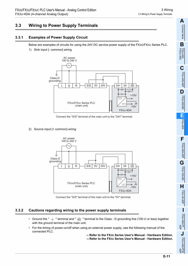
3 Wiring3.3 Wiring to Power Supply Terminals
A
Comm
on Items
B
FX3U-4ADFX3UC-4AD
C
FX3U-4AD-ADP
D
FX3G-2AD-BD
E
FX3U-4DA
F
FX3U-4DA-ADP
G
FX3G-1DA-BD
H
FX3U-3A-ADP
I
FX3U-4AD-PT -ADP
J
FX3U-4AD-PTW -ADP
FX3G/FX3U/FX3UC PLC User's Manual - Analog Control EditionFX3U-4DA (4-channel Analog Output)
3.3 Wiring to Power Supply Terminals
3.3.1 Examples of Power Supply Circuit
Below are examples of circuits for using the 24V DC service power supply of the FX3G/FX3U Series PLC.1) Sink input [- common] wiring
2) Source input [+ common] wiring
3.3.2 Cautions regarding wiring to the power supply terminals
• Ground the " " terminal and " " terminal to the Class - D grounding line (100 Ω or less) together with the ground terminal of the main unit.
• For the timing of power-on/off when using an external power supply, see the following manual of the connected PLC.
→ Refer to the FX3G Series User's Manual - Hardware Edition.→ Refer to the FX3U Series User's Manual - Hardware Edition.
Class-Dgrounding
L N
FX3G/FX3U Series PLC(main unit)
24+ 24-S/S 0V 24V
+15V
-15V
FX3U-4DA
AC power100 to 240 V
Connect the "S/S" terminal of the main unit to the "24V" terminal.
Class-Dgrounding
L N
(main unit)
24+ 24-S/S 0V 24V
+15V
-15V
FX3U-4DA
AC power100 to 240 V
Connect the "S/S" terminal of the main unit to the "0V" terminal.
FX3G/FX3U Series PLC
E-11
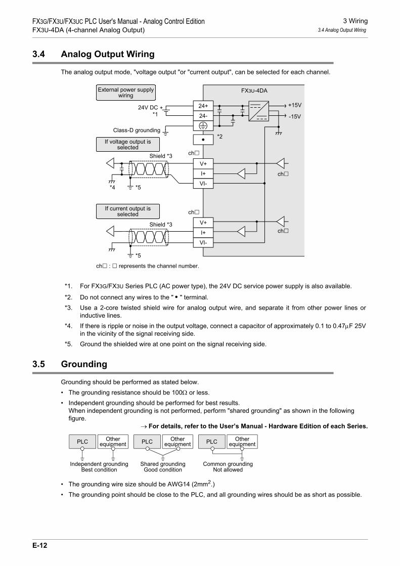
3 Wiring3.4 Analog Output Wiring
FX3G/FX3U/FX3UC PLC User's Manual - Analog Control EditionFX3U-4DA (4-channel Analog Output)
3.4 Analog Output Wiring
The analog output mode, "voltage output "or "current output", can be selected for each channel.
*1. For FX3G/FX3U Series PLC (AC power type), the 24V DC service power supply is also available.
*2. Do not connect any wires to the " • " terminal.*3. Use a 2-core twisted shield wire for analog output wire, and separate it from other power lines or
inductive lines.*4. If there is ripple or noise in the output voltage, connect a capacitor of approximately 0.1 to 0.47µF 25V
in the vicinity of the signal receiving side. *5. Ground the shielded wire at one point on the signal receiving side.
3.5 Grounding
Grounding should be performed as stated below.• The grounding resistance should be 100Ω or less.• Independent grounding should be performed for best results.
When independent grounding is not performed, perform "shared grounding" as shown in the following figure.
→ For details, refer to the User’s Manual - Hardware Edition of each Series.
• The grounding wire size should be AWG14 (2mm2.)• The grounding point should be close to the PLC, and all grounding wires should be as short as possible.
FX3U-4DA
+15V
I+
VI-
V+
24+
24- -15V
I+
VI-
V+
ch : represents the channel number.
ch
Shield *3
24V DC
If voltage output isselected
If current output isselected
External power supplywiring
*1
ch
ch
Class-D grounding*2
chShield *3
*4 *5
*5
PLC OtherequipmentPLC Other
equipmentPLC Otherequipment
Shared groundingGood condition
Common groundingNot allowed
Independent groundingBest condition
E-12

4 Analog Output4.1 Analog Output Procedures
A
Comm
on Items
B
FX3U-4ADFX3UC-4AD
C
FX3U-4AD-ADP
D
FX3G-2AD-BD
E
FX3U-4DA
F
FX3U-4DA-ADP
G
FX3G-1DA-BD
H
FX3U-3A-ADP
I
FX3U-4AD-PT -ADP
J
FX3U-4AD-PTW -ADP
FX3G/FX3U/FX3UC PLC User's Manual - Analog Control EditionFX3U-4DA (4-channel Analog Output)
4. Analog Output
This chapter describes the minimum programming necessary for analog output by the FX3U-4DA. Follow the procedure below to confirm that correct analog values can be output.
4.1 Analog Output Procedures
1 Unit number check
Unit numbers from 0 to 7 will be assigned to the special function units/blocks starting from the left.When the units/blocks are connected to the FX3UC-32MT-LT(-2) PLC, the unit numbers from 1 to 7are assigned. Check the unit number assigned to the FX3U-4DA.
2 Output mode (BFM #0) setting
Depending on the analog signal generator to be connected, set the output mode (BFM #0) for eachchannel.
Use hexadecimal numbers for output mode setting. Set the corresponding channel digit to theoutput mode setting value specified in the following table:
→ For a detailed description of the standard output characteristics, refer to Section 2.4.→ For a detailed description of the output mode (BFM #0), refer to Subsection 5.4.1.
Settingvalue Output mode Analog output range Digital input range
0 Voltage output mode -10V to +10V -32000 to +32000
1 Voltage output analog value mV specification mode -10V to +10V -10000 to +10000
2 Current output mode 0mA to 20mA 0 to 32000
3 Current output mode 4mA to 20mA 0 to 32000
4 Current output analog value µA specification mode 0mA to 20mA 0 to 20000
F Channel not used
Main unit(FX3U Series
PLC)
Input/outputextension
blockSpecial
function blockSpecial
function blockInput/outputextension
blockSpecial
function unit
Unitnumber: 0
Unitnumber: 1
Unitnumber: 2
Hch4ch3 ch2
ch1
E-13

4 Analog Output4.1 Analog Output Procedures
FX3G/FX3U/FX3UC PLC User's Manual - Analog Control EditionFX3U-4DA (4-channel Analog Output)
3 Creation of sequence programCreate the program as follows to output analog signals.• While referring to step 2, set the output mode "H****".• While referring to step 1, set the unit number in
- Program Example (For FX3U, FX3UC Series PLCs)*1
*1. Use the FROM and TO instructions in FX3G PLCs.
4 Transfer of sequence program and analog output signal check1) Transfer the sequence program, and start the PLC.2) Check that analog signals appropriate to the set output data are output.
→ If analog signals are not output correctly, refer to Chapter 9 "Troubleshooting."
M8002FNC 12
MOVH**** U\G0
P
M8000K50T0
T0
Specify the output mode (BFM #0) for channels1 to 4.
Initial pulse
FNC 15BMOV
D0 U\G1 K4Data (BMF #1 to 4) to be output to channels 1to 4 are transferred from D0 to D3.
Output mode (step 2)
Unit number (step 1)
Unit number (step 1)
RUN monitor
Data to be output to channel 1 is written in D0.Data to be output to channel 2 is written in D1.Data to be output to channel 3 is written in D2.Data to be output to channel 4 is written in D3.
Data to be output to channels 1 to 4 are stored inD0 to D3.
E-14

5 Buffer Memory (BFM)5.1 Assignment of Unit Numbers and Outline of Buffer Memory
A
Comm
on Items
B
FX3U-4ADFX3UC-4AD
C
FX3U-4AD-ADP
D
FX3G-2AD-BD
E
FX3U-4DA
F
FX3U-4DA-ADP
G
FX3G-1DA-BD
H
FX3U-3A-ADP
I
FX3U-4AD-PT -ADP
J
FX3U-4AD-PTW -ADP
FX3G/FX3U/FX3UC PLC User's Manual - Analog Control EditionFX3U-4DA (4-channel Analog Output)
5. Buffer Memory (BFM)
This chapter describes the buffer memory incorporated in FX3U-4DA.
5.1 Assignment of Unit Numbers and Outline of Buffer Memory
1. Assignment of unit numbersUnit numbers from 0 to 7 will be assigned to the special function units/blocks starting from the left one. When the units/blocks are connected to the FX3UC-32MT-LT(-2) PLC, unit numbers from 1 to 7 are assigned.
When connected to the FX3G/FX3U/FX3UC (D, DS, DSS) Series PLC
When connected to the FX3UC-32MT-LT(-2) PLC
Main unitInput/outputextension
blockSpecial
function blockSpecial
function blockInput/outputextension
blockSpecial
function unit
Unitnumber: 0
Unitnumber: 1
Unitnumber: 2
Main unit(FX3UC-32MT
-LT(-2))
Input/outputextension
block
Specialfunction block
Specialfunction block
Input/outputextension
block
Specialfunction unit
Unit number: 0(IncorporatedCC-Link/LT)
Unitnumber: 1
Unitnumber: 2
Unitnumber: 3
E-15

5 Buffer Memory (BFM)5.2 Buffer Memory Reading/Writing Method
FX3G/FX3U/FX3UC PLC User's Manual - Analog Control EditionFX3U-4DA (4-channel Analog Output)
2. Outline of buffer memoryThe digital values set in FX3U-4DA will be converted to analog signals.To switch the output mode between voltage output and current output, or to adjust the offset or gain, numericdata will be sent from the main unit and written/set in the FX3U-4DA buffer memory.To read/write data from/into the buffer memory of FX3U-4DA, the buffer memory can be directly specifiedusing FROM/TO instructions or an applied instruction. Using this function, sequence programs can be easilycreated.
→ For a detailed description of buffer memory reading/writing, refer to Section 5.2.→ For a detailed description of the buffer memory, refer to Section 5.4.
5.2 Buffer Memory Reading/Writing Method
To read or write the buffer memory of FX3U-4DA, use FROM/TO instructions or the buffer memory direct specification function*1.To use the buffer memory direct specification function*1, however, it is necessary to adopt the software compatible with the FX3U/FX3UC Series PLC.
*1. This function is supported only in FX3U/FX3UC PLCs.→ For a detailed description of the software compatible with the FX3U/FX3UC Series PLC,
refer to Section 1.4.
*1. Since buffer memory direct specification (U\G) can directly specify the buffer memory in the source
or destination area of an applied instruction, programs can be created efficiently. (This function is supported
only in FX3U/FX3UC PLCs.)
FX3U/FX3UC
Series PLC
Sequenceprogram
FX3U-4DA
Buffermemory
D/Aconversion
FX3U-4DA
Buffermemory
D/Aconversion
Analog dataAnalog data
Digitalvalue
Digitalvalue
Inverter, DC motor, etc.
• TO instruction
• FROM instruction
• BFM direct
specification*1
• BFM direct
specification*1
• TO instruction
• BFM direct
specification*1
• FROM instruction
• BFM direct
specification*1
E-16

5 Buffer Memory (BFM)5.2 Buffer Memory Reading/Writing Method
A
Comm
on Items
B
FX3U-4ADFX3UC-4AD
C
FX3U-4AD-ADP
D
FX3G-2AD-BD
E
FX3U-4DA
F
FX3U-4DA-ADP
G
FX3G-1DA-BD
H
FX3U-3A-ADP
I
FX3U-4AD-PT -ADP
J
FX3U-4AD-PTW -ADP
FX3G/FX3U/FX3UC PLC User's Manual - Analog Control EditionFX3U-4DA (4-channel Analog Output)
5.2.1 Buffer memory direct specification (FX3U, FX3UC PLC only)
When directly specifying the buffer memory, specify the following device in the source or destination area ofthe applied instruction as follows:
1. Example 1If the following program is created, data in buffer memory (BFM #10) of unit 1 will be multiplied by the data(K10), and then the multiplication result will be output to the data registers (D10, D11).
2. Example 2If the following program is created, the value in the data register (D20) is added to K10 and written to buffermemory (BFM #6) of unit 1.
5.2.2 FROM/TO instruction (FX3G, FX3U, FX3UC PLC)
1. FROM instruction (Reading out BFM data to PLC)Use FROM instruction to read out the data from the buffer memory.In a sequence program, use this instruction as follows:
If the above program is created, 1 point of data will be read out from the buffer memory BFM #10 of unit No.1 to the data register (D10).
2. TO instruction (Writing PLC data into BFM)Use the TO instruction to write data to a buffer memory.In a sequence program, use this instruction as follows:
If the above program is created, 1 point of data (H3300) will be written to buffer memory (BFM #0) of unitNo.1.
Buffer memory number (0 - 3098)
U \G Enter a numeric value in
Unit number (0 to 7)
FNC 22MUL
U1\G10 K10 D10
MultiplierMultiplication resultUnit number
Buffer memory number
READ command
WRITE commandFNC 20
ADDD20 K10 U1\G6
AddendAugend
Unit numberBuffer memory number
Additionresult ( )
READ command FNC 78FROM
K1 K10 D10 K1
Transfer-to register
Number of transferdata pointsUnit number
Buffer memory number
WRITE commandFNC 79
TOK1 K0 H3300 K1
Transfer source
Number of transferdata pointsUnit number
Buffer memory number
E-17

5 Buffer Memory (BFM)5.3 Buffer Memory List (BFM)
FX3G/FX3U/FX3UC PLC User's Manual - Analog Control EditionFX3U-4DA (4-channel Analog Output)
5.3 Buffer Memory List (BFM)
FX3U-4DA incorporates the following buffer memories.→ For a detailed description of the buffer memory, refer to Section 5.4 and subsequent sections.
*1. If power failure occurs, the EEPROM will retain the data.*2. Specify the output mode of each channel setting one of hex code 0 to 4 and F in each digit.*3. Specify the data to be output from each channel upon PLC stop setting one of hex code 0 to 2 in each
digit.*4. Use b0 to b3.
BFM number Description Setting range Initial value Data type Reference
#0*1 Output mode setting for channels 1 to 4 *2 H0000 at delivery Hexadeci-mal
Subsection 5.4.1
#1 Channel 1 output data
Depending on the mode used
K0 Decimal
Subsection 5.4.2
#2 Channel 2 output data K0 Decimal
#3 Channel 3 output data K0 Decimal
#4 Channel 4 output data K0 Decimal
#5*1 Output setting upon PLC stop *3 H0000 Hexadeci-mal
Subsection 5.4.3
#6 Output status - H0000 Hexadeci-mal
Subsection 5.4.4
#7, #8 Not used - - - -
#9 Command to write offset/gain setting value of channels 1 to 4 *4 H0000 Hexadeci-
malSubsection
5.4.5
#10*1 Channel-1 offset data (Unit: mV or µA)
Depending on the mode used
Depending on the mode used
Decimal
Subsection 5.4.6
#11*1 Channel-2 offset data (Unit: mV or µA) Decimal
#12*1 Channel-3 offset data (Unit: mV or µA) Decimal
#13*1 Channel-4 offset data (Unit: mV or µA) Decimal
#14*1 Channel-1 gain data (Unit: mV or µA)
Depending on the mode used
Depending on the mode used
Decimal
Subsection 5.4.6
#15*1 Channel-2 gain data (Unit: mV or µA) Decimal
#16*1 Channel-3 gain data (Unit: mV or µA) Decimal
#17*1 Channel-4 gain data (Unit: mV or µA) Decimal
#18 Not used - - - -
#19*1 Setting change prohibition
To permit data change: K3030To disable data change: Value
other than K3030
K3030 at delivery Decimal Subsection 5.4.7
#20
Initialization function:Set "K1" in this buffer memory to perform initialization. At the completion of initialization, the "K0" will be automatically set.
K0 or K1 K0 Decimal Subsection 5.4.8
#21 to #27 Not used - - - -
#28 Disconnection detection status (Valid only in current mode selection) - H0000 Hexadeci-
malSubsection
5.4.9
#29 Error status - H0000 Hexadeci-mal
Subsection 5.4.10
#30 Model code K3030 - K3030 Decimal Subsection 5.4.11
#31 Not used - - - -
E-18

5 Buffer Memory (BFM)5.3 Buffer Memory List (BFM)
A
Comm
on Items
B
FX3U-4ADFX3UC-4AD
C
FX3U-4AD-ADP
D
FX3G-2AD-BD
E
FX3U-4DA
F
FX3U-4DA-ADP
G
FX3G-1DA-BD
H
FX3U-3A-ADP
I
FX3U-4AD-PT -ADP
J
FX3U-4AD-PTW -ADP
FX3G/FX3U/FX3UC PLC User's Manual - Analog Control EditionFX3U-4DA (4-channel Analog Output)
*1. If power failure occurs, the EEPROM will retain the data.*2. Specify the use of the upper/lower limit function for each channel setting one of hex code 0 to 2 in
each digit.*3. Use b0 to b1.*4. Specify the use of the corrective function by load resistance for each channel setting a hex code 0 or
1 in each digit.*5. Use b0 to b2.
BFM number Description Setting range Initial value Data type Reference
#32*1 Data to be output from channel 1 upon PLC stop (Valid only if BFM #5 = H 2)
Depending on the mode used K0 Decimal
Subsection 5.4.12
#33*1 Data to be output from channel 2 upon PLC stop (Valid only if BFM #5 = H 2 )
Depending on the mode used K0 Decimal
#34*1 Data to be output from channel 3 upon PLC stop (Valid only if BFM #5 = H 2 )
Depending on the mode used K0 Decimal
#35*1 Data to be output from channel 4 upon PLC stop (Valid only if BFM #5 = H2 )
Depending on the mode used K0 Decimal
#36, #37 Not used - - - -
#38 Upper/lower limit function setting *2 H0000 Hexadeci-mal
Subsection 5.4.13
#39 Upper/lower limit function status - H0000 Hexadeci-mal
Subsection 5.4.14
#40 Clear of upper/lower limit function status *3 H0000 Hexadeci-mal
Subsection 5.4.15
#41 Channel-1 lower limit of upper/lower limit function
Depending on the mode used
K-32640 Decimal
Subsection 5.4.16
#42 Channel-2 lower limit of upper/lower limit function K-32640 Decimal
#43 Channel-3 lower limit of upper/lower limit function K-32640 Decimal
#44 Channel-4 lower limit of upper/lower limit function K-32640 Decimal
#45 Channel-1 upper limit of upper/lower limit function
Depending on the mode used
K32640 Decimal
Subsection 5.4.16
#46 Channel-2 upper limit of upper/lower limit function K32640 Decimal
#47 Channel-3 upper limit of upper/lower limit function K32640 Decimal
#48 Channel-4 upper limit of upper/lower limit function K32640 Decimal
#49 Not used - - - -
#50*1 Corrective function setting by load resistance (Valid only in voltage output mode) *4 H0000 Hexadeci-
malSubsection
5.4.17
#51*1 Load resistance value for channel 1 (Unit: Ω) K1000 to K30000 K30000 Decimal
Subsection5.4.17
#52*1 Load resistance value for channel 2 (Unit: Ω) K1000 to K30000 K30000 Decimal
#53*1 Load resistance value for channel 3 (Unit: Ω) K1000 to K30000 K30000 Decimal
#54*1 Load resistance value for channel 4 (Unit: Ω) K1000 to K30000 K30000 Decimal
#55 to #59 Not used - - - -
#60*1 Status automatic transfer function setting *5 K0 Decimal Subsection 5.4.18
#61*1Error status data (BFM #29) automatic transfer-to data register specification (Valid if b0 of BFM #60 is set to ON)
K0 to 7999 (BFM #61, #62 and #63
must have different values.)
K200 Decimal Subsection 5.4.19
#62*1Upper/lower limit function status data (BFM #39) automatic transfer-to data register specification (Valid if b1 of BFM #60 is set to ON)
K201 Decimal Subsection 5.4.20
#63*1Disconnection detection status data (BFM #28) automatic transfer-to data register specification (Valid if b2 of BFM #60 is set to ON)
K202 Decimal Subsection 5.4.21
#64 to #79 Not used - - - -
E-19

5 Buffer Memory (BFM)5.3 Buffer Memory List (BFM)
FX3G/FX3U/FX3UC PLC User's Manual - Analog Control EditionFX3U-4DA (4-channel Analog Output)
BFM number Description Setting range Initial value Data type Reference
#80 Start/stop of table output function *1 H0000 Hexadeci-mal
Chapter 6
#81 Channel-1 output pattern K1 to K10 K1 Decimal
#82 Channel-2 output pattern K1 to K10 K1 Decimal
#83 Channel-3 output pattern K1 to K10 K1 Decimal
#84 Channel-4 output pattern K1 to K10 K1 Decimal
#85 Number of times of output execution of table from channel 1 K0 to K32767 K0 Decimal
#86 Number of times of output execution of table from channel 2 K0 to K32767 K0 Decimal
#87 Number of times of output execution of table from channel 3 K0 to K32767 K0 Decimal
#88 Number of times of output execution of table from channel 4 K0 to K32767 K0 Decimal
#89 Output completion flag of table output function - H0000 Hexadeci-mal
#90 Table output error code - K0 Decimal
#91 Table output error occurrence number - K0 Decimal
#92 to #97 Not used - - - -
#98 Head device number in data table K0 to K32767 K1000 Decimal
Chapter 6#99 Data table transfer command *2 H0000 Hexadeci-mal
#100 to #398 Data table in pattern 1 - K0 Decimal
#399 Not used - - - -
#400 to #698 Data table in pattern 2 - K0 Decimal Chapter 6
#699 Not used - - - -
#700 to #998 Data table in pattern 3 - K0 Decimal Chapter 6
#999 Not used - - - -
#1000 to #1298 Data table in pattern 4 - K0 Decimal Chapter 6
#1299 Not used - - - -
#1300 to #1598 Data table in pattern 5 - K0 Decimal Chapter 6
#1599 Not used - - - -
#1600 to #1898 Data table in pattern 6 - K0 Decimal Chapter 6
#1899 Not used - - - -
#1900 to #2198 Data table in pattern 7 - K0 Decimal Chapter 6
#2199 Not used - - - -
#2200 to #2498 Data table in pattern 8 - K0 Decimal Chapter 6
#2499 Not used - - - -
#2500 to #2798 Data table in pattern 9 - K0 Decimal Chapter 6
#2799 Not used - - - -
#2800 to #3098 Data table in pattern 10 - K0 Decimal Chapter 6
*1. Specify whether to start or stop the table output function for each channel setting a hex code 0 or 1in each digit.
*2. Specify the data table transfer command and the register type setting 0 or 1 in the last two digits ofthe hex code.
E-20

5 Buffer Memory (BFM)5.4 Buffer Memory Details
A
Comm
on Items
B
FX3U-4ADFX3UC-4AD
C
FX3U-4AD-ADP
D
FX3G-2AD-BD
E
FX3U-4DA
F
FX3U-4DA-ADP
G
FX3G-1DA-BD
H
FX3U-3A-ADP
I
FX3U-4AD-PT -ADP
J
FX3U-4AD-PTW -ADP
FX3G/FX3U/FX3UC PLC User's Manual - Analog Control EditionFX3U-4DA (4-channel Analog Output)
5.4 Buffer Memory Details
5.4.1 BFM #0: Output mode specification
Initial value (at delivery): H0000Numeric data type: Hexadecimal (H)
Specify the output modes of channel 1 to 4.4 hexadecimal digits are assigned to specify the output modes of the 4 channels. Change the value of each digit to change the output mode of each channel. 0 to 4 and F can be set for eachdigit.
The different types of output modes are shown in the following table:→ For a detailed description of output characteristics, refer to Section 2.4.
*1. The offset/gain values cannot be changed.
1. Cautions regarding output mode setting• While the output mode is being changed, the output is stopped, and H0000 is automatically written in the
output status (BFM #6).At the completion of change of the output mode, the output status (BFM #6) will automatically change to H1111, and the output is restarted.
• It takes approximately 5 seconds to determine the output mode.For this reason, after changing the output mode, be sure to wait for 5 seconds or more, and then write the other data.
• When the output mode is changed, the settings in the following buffer memory are initialized according to the new output mode.
BFM #5 (output setting upon PLC stop)*1
BFM #10 to #13 (offset data)*2
BFM #14 to #17 (gain data)*2
BFM #28 (disconnection detection status)*3 BFM #32 to #35 (output data upon PLC stop)*2
BFM #38 (upper/lower limit function setting)*1
BFM #41 to #44 (lower limit values of upper/lower limit function)*2
BFM #45 to #48 (upper limit values of upper/lower limit function)*2
BFM #50 (Setting of output corrective function by load resistance)*1*1 FX3U-4DA initializes the corresponding bit to the channel where the user has changed the output mode.*2 FX3U-4DA initializes the corresponding buffer memory to the channel where the user has changed the
output mode.*3 These settings are initialized only when the output mode is changed from current output mode
(mode 2, 3 or 4) to voltage output mode (mode 0 or 1).• HFFFF (use of no channels) cannot be set.
Set value[HEX] Output mode Analog output range Digital input range
0 Voltage output mode -10V to +10V -32000 to +32000
1*1 Voltage output analog value mV specification mode -10V to +10V -10000 to +10000
2 Current output mode 0mA to 20mA 0 to 32000
3 Current output mode 4mA to 20mA 0 to 32000
4*1 Current output analog value µA specification mode 0mA to 20mA 0 to 20000
5 to E Invalid (setting values unchanged) - -
F Channel not used
Hch4ch3 ch2
ch1
E-21

5 Buffer Memory (BFM)5.4 Buffer Memory Details
FX3G/FX3U/FX3UC PLC User's Manual - Analog Control EditionFX3U-4DA (4-channel Analog Output)
2. Caution regarding EEPROM writingIf data is written to BFM #0, #5, #10 to #17, #19, #32 to #35, #50 to #54 or #60 to #63, the data will also bewritten to the FX3U-4DA EEPROM.Do not turn off the power immediately after writing values in these buffer memories.The maximum number of EEPROM rewrites is 10,000 times. Therefore, when creating a program, do notfrequently write data to the above buffer memories (BFM).
5.4.2 BFM #1 to #4: Output data
Initial value: K0Numeric data type: Decimal (K)
Input the digital values corresponding to the analog signals to be output in BFM #1 to #4.
5.4.3 BFM #5: Output setting upon PLC stop
Initial value: H0000Numeric data type: Hexadecimal (H)
It is possible to set the output conditions from channel 1 to 4 when the PLC is in the stopped state.
* The output conditions depend on the output mode (BFM #0).
1. Cautions regarding output conditions setting upon PLC stop• While changing the setting values, the output is stopped, and H0000 is automatically written in the output
status (BFM #6).At the completion of change, the output status (BFM #6) will automatically change to H1111, and output will be restarted.
2. Caution regarding EEPROM writing• If data is set in BFM #0, #5, #10 to #17, #19, #32 to #35, #50 to #54 or #60 to #63, the data will be written
in the EEPROM of FX3U-4DA.Do not turn off the power immediately after writing values in these buffer memories.The maximum number of EEPROM rewritable times is 10,000 times. Therefore, when creating a program, do not frequently write data to the above buffer memories (BFM).
BFM number Description#1 Data to be output from channel 1
#2 Data to be output from channel 2
#3 Data to be output from channel 3
#4 Data to be output from channel 4
Set value (HEX) Output conditions0 The final value during running is held.1 The offset signal is output.*2 The output data set in BFM #32 to #35 are output.*
3 to F Invalid (setting values unchanged)
Hch4ch3 ch2
ch1
E-22

5 Buffer Memory (BFM)5.4 Buffer Memory Details
A
Comm
on Items
B
FX3U-4ADFX3UC-4AD
C
FX3U-4AD-ADP
D
FX3G-2AD-BD
E
FX3U-4DA
F
FX3U-4DA-ADP
G
FX3G-1DA-BD
H
FX3U-3A-ADP
I
FX3U-4AD-PT -ADP
J
FX3U-4AD-PTW -ADP
FX3G/FX3U/FX3UC PLC User's Manual - Analog Control EditionFX3U-4DA (4-channel Analog Output)
5.4.4 BFM #6: Output status
Initial value: H0000Numeric data type: Hexadecimal (H)
The output status information of channel 1 to 4 is stored.
* The output conditions conform to the output setting upon PLC stop (BFM #5).
1. Cautions regarding use of output status• The output status setting is valid only if the PLC is running.
When the PLC is stopped, H0000 is automatically written.• When the setting in any of the following buffer memory areas is changed, output updating is stopped.
H0000 is automatically written in BFM #6.• BFM #0 (Output mode setting)• BFM #5 (Output setting upon PLC stop)• BFM #9 (Offset/gain setting value write command)• BFM #19 (Setting change prohibition)• BFM #20 (Initialization function)• BFM #32 to #35 (Data to be output from each channel upon PLC stop)• BFM #50 (Corrective function setting by load resistance)• BFM #51 to #54 (Load resistance for each channel)• BFM #60 (Status automatic transfer function Setting)• BFM #61 (Error status data automatic transfer-to data register specification)• BFM #62 (Upper/lower limit function status with automatic transfer to specified data register)• BFM #63 (Disconnection detection status with automatic transfer to data register specification)• BFM #99 (Data table transfer command)
Value status (HEX) Description0 Output updating is stopped.*1 Under output updating
Hch4ch3 ch2
ch1
E-23

5 Buffer Memory (BFM)5.4 Buffer Memory Details
FX3G/FX3U/FX3UC PLC User's Manual - Analog Control EditionFX3U-4DA (4-channel Analog Output)
5.4.5 BFM #9: Offset/gain setting value write command
Initial value: H0000Numeric data type: Hexadecimal (H)
Channel numbers are assigned to 4 lower bits of BFM #9. If one of those bits is turned on, the offset data(BFM #10 to #13) and the gain data (BFM #14 to #17) of the corresponding channel will be written in theinternal memory (EEPROM). When written in the internal memory, the data will be valid.
1. Channel number assignment to each bit of BFM #9
The WRITE command can be given to two or more channels at the same time. (Set "H000F" to write the dataof all the channels in the EEPROM.) On completion of writing, "H0000" (b0 to b3: OFF) will be set automatically.
2. Cautions regarding giving offset/gain setting value write command• While changing the setting, the output is stopped, and H0000 is automatically written in the output status
(BFM #6).At the completion of writing, the output status (BFM #6) will automatically change to H1111, and output will be restarted.
• If the analog value specification mode (mode 1 or 4) is used, the offset/gain cannot be changed.When other output mode has been set, it is possible to change to same characteristics as those in the output mode 1 or 4.
• If the write command is not executed, the offset and gain data will not be stored in the EEPROM.• When b1 of the error status (BFM #29) is set to ON, the offset and gain data will not be stored in the
EEPROM.→ For a detailed description of offset and gain setting, refer to Subsection 5.4.6.
Bit No. Descriptionb0 Channel-1 offset data (BFM #10) and gain data (BFM #14) writingb1 Channel-2 offset data (BFM #11) and gain data (BFM #15) writingb2 Channel-3 offset data (BFM #12) and gain data (BFM #16) writingb3 Channel-4 offset data (BFM #13) and gain data (BFM #17) writing
b4 to b15 Not used
E-24

5 Buffer Memory (BFM)5.4 Buffer Memory Details
A
Comm
on Items
B
FX3U-4ADFX3UC-4AD
C
FX3U-4AD-ADP
D
FX3G-2AD-BD
E
FX3U-4DA
F
FX3U-4DA-ADP
G
FX3G-1DA-BD
H
FX3U-3A-ADP
I
FX3U-4AD-PT -ADP
J
FX3U-4AD-PTW -ADP
FX3G/FX3U/FX3UC PLC User's Manual - Analog Control EditionFX3U-4DA (4-channel Analog Output)
5.4.6 BFM #10 to #13: Offset data/BFM #14 to #17: Gain data
Setting range: See belowInitial value: See below
Numeric data type: Decimal (K)
If the output mode is specified in BFM #0, the initial value of the offset data and gain data of each channel willbe automatically stored.The initial offset data and the gain data are set for each mode as shown in the following table:• Offset data: Analog output value when the output data in BFM #1 to #4 are 0 (reference offset value)• Gain data: Analog output value when the output data in BFM #1 to #4 are the reference gain values (The
reference gain value depends on the set output mode.)
1. Reference offset/gain value and initial value set
2. Offset/gain data changeSet offset data and gain data to change the output characteristics.The offset and gain data can be set for each channel. If the voltage output mode is set, write the offset andgain data in mV. If the current output mode is set, write the offset and gain data in µA.To change the offset or gain data, execute the offset/gain setting value write command (BFM #9).The setting range is shown in the following table.
*1. The offset and gain values should meet the following conditions:1000 ≤ Gain value - Offset value ≤ 10000
*2. The offset and gain values should meet the following conditions:3000 ≤ Gain value - Offset value ≤ 30000
Output mode (BFM #0) Offset (channels 1 to 4: BFM #10 to #13)
Gain (channels 1 to 4: BFM #14 to #17)
Set value Description Reference value Initial value Reference
value Initial value
0 Voltage output (-10 V to +10 V: -32000 to +32000) 0 0mV 16000 5000mV
1Voltage output Analog value mV specification mode(-10 V to +10 V: -10000 to +10000)
0(Data change impossible)
0mV(Data change impossible)
5000(Data change impossible)
5000mV(Data change impossible)
2 Current output (0 mA to 20 mA: 0 to 32000) 0 0µA 16000 10000µA
3 Current output (4 mA to 20 mA: 0 to 32000) 0 4000µA 16000 12000µA
4Current output Analog value µA specification mode(0 mA to 20 mA: 0 to 20000)
0(Data change impossible)
0µA(Data change impossible)
10000(Data change impossible)
10000µA(Data change impossible)
Voltage output (mV) Current output (µA)
Offset data -10000 to +9000*1 0 to 17000*2
Gain data -9000 to +10000*1 3000 to 30000*2
E-25

5 Buffer Memory (BFM)5.4 Buffer Memory Details
FX3G/FX3U/FX3UC PLC User's Manual - Analog Control EditionFX3U-4DA (4-channel Analog Output)
3. Cautions regarding offset/gain data change• If the analog value specification mode (mode 1 or 4) is used, the offset/gain cannot be changed. However,
the characteristics can be changed as those in the output mode 1 or 4 by setting the following offset and gain data in the output mode 0 or 2.
• The offset and gain data should be set before the value write command BFM #9 is executed.• The resolution cannot be increased by changing the output characteristics.• When the value specified as the output mode (BFM #0) is changed, the initial value of offset and gain data
in each output mode will be automatically written.• Even if the output characteristics are changed, the actual valid output range will not be changed:
-10 V to +10 V for the voltage output mode, and 0 mA to 20 mA in the current output mode.→ For a detailed description of output characteristics change, refer to Chapter 7.
5.4.7 BFM #19: Data change prohibition of setting change
Setting range: K3030 or other than K3030Initial value: K3030
Numeric data type: Decimal (K)
Setting in the following buffer memory areas is prohibited.• BFM #0 (output mode setting Output mode setting)
BFM #5 (output setting upon PLC stop)BFM #9 (offset/gain setting value write command)BFM #10 to #13 (offset data)BFM #14 to #17 (gain data)BFM #20 (initialization function)BFM #32 to #35 (data to be output upon PLC stop)BFM #38 (upper/lower limit function setting)BFM #41 to #48 (upper and lower limit values of upper/lower limit function)BFM #50 (corrective function setting by load resistance)BFM #51 to #54 (load resistance values)BFM #60 (status automatic transfer function setting)BFM #61 (Error status data automatic transfer-to data register specification)BFM #62 (Upper/lower limit function status with automatic transfer to specified register specification)BFM #63 (Disconnection detection status with automatic transfer to specified data register specification)
Specify the following value as the setting change prohibition mode (BFM #19).
1. Cautions regarding setting of the setting change prohibition mode• While changing the setting value, the output is stopped, and H0000 is automatically written in the output
status (BFM #6).At the completion of writing, the output status (BFM #6) will automatically change to H1111, and the output will be restarted.
2. Cautions regarding EEPROM writingIf data is set in BFM #0, #5, #10 to #17, #19, #32 to #35, #50 to #54 or #60 to #63, the data will be written inthe EEPROM of FX3U-4DA.Do not turn off power immediately after writing values in these buffer memoriesThe maximum number of EEPROM rewritable times is 10,000. Therefore, when creating a program, do notfrequently write data in the above buffer memories (BFM).
Offset data Gain dataChange characteristics from output mode 0 to 1 0 16000Change characteristics from output mode 2 to 4 0 16000
Set value DescriptionK3030 permits data change
Other than K3030 disables data change
E-26

5 Buffer Memory (BFM)5.4 Buffer Memory Details
A
Comm
on Items
B
FX3U-4ADFX3UC-4AD
C
FX3U-4AD-ADP
D
FX3G-2AD-BD
E
FX3U-4DA
F
FX3U-4DA-ADP
G
FX3G-1DA-BD
H
FX3U-3A-ADP
I
FX3U-4AD-PT -ADP
J
FX3U-4AD-PTW -ADP
FX3G/FX3U/FX3UC PLC User's Manual - Analog Control EditionFX3U-4DA (4-channel Analog Output)
5.4.8 BFM #20: Initialization function (resetting to factory default status)
Setting range: K0 or K1Initial value: K0
Numeric data type: Decimal (K)When K1 is set in BFM #20, all functions and all buffer memory (BFM #0 to #3098) will be initialized to thedefault status.When BFM #20 is not K0 or K1, this function is invalid. (The settings will not be changed, and the functionswill not be initialized.)
1. Cautions regarding initialization function• During initialization, output is stopped, and H0000 is automatically written in the output status (BFM #6).
At the completion of initialization, the output status (BFM #6) will automatically change to H1111, and output will be restarted.
• It takes approximately 5 seconds to initialize all the data. Do not set (write) data in the buffer memory during this period.
• Priority is given to the setting of the value change prohibition mode (BFM #19).• At the completion of initialization, the value of BFM #20 will automatically change to K0.
5.4.9 BFM #28: Disconnection detection status (only in current output mode)
Initial value: H0000Numeric data type: Hexadecimal (H)
When a wire-break is detected, the bit corresponding to the relevant channel will turn on.
1. Assignment to each bit of BFM #28
2. Cautions regarding use of disconnection detection status• When any of b0 to b3 is turned on, b11 of the error status (BFM #29) is turned on.• The disconnection detection status is valid only if the output mode (BFM #0) is the current output mode
(mode 2 to 4). In other output modes, each corresponding bit of BFM #28 stays off.
3. Disconnection detection status automatic transfer function (b2 of BFM #60)If the disconnection detection status with automatic transfer-to data register is specified in BFM #63, the datain BFM #28 can be transferred to the specified data register.Only when wire-break is detected, data will be automatically transferred from FX3U-4DA to the PLC. For thisreason, the PLC does not need the program for reading data, and the scan time of the PLC can be shortened.
→ For a detailed description of the status automatic transfer function, refer to Subsection 5.4.18.
Bit No. Descriptionb0 Wire-break in channel 1b1 Wire-break in channel 2b2 Wire-break in channel 3b3 Wire-break in channel 4
b4 to b15 Not used
E-27

5 Buffer Memory (BFM)5.4 Buffer Memory Details
FX3G/FX3U/FX3UC PLC User's Manual - Analog Control EditionFX3U-4DA (4-channel Analog Output)
5.4.10 BFM #29: Error status
Initial value: H0000Numeric data type: Hexadecimal (H)
Error data is assigned each bit of BFM #29.
2. Caution regarding error statusIf the error cause is eliminated, the error bit will turn off.
3. Error status data automatic transfer function (b0 of BFM #60)If the error status with automatic transfer to data register is specified in BFM #61, the data in BFM #29 can betransferred to a specified data register.Only when an error is detected, data will be automatically transferred from FX3U-4DA to the PLC. For thisreason, the PLC does not need the program for reading data, and the scan time of the PLC can be shortened.
→ For a detailed description of the status automatic transfer function, refer to Subsection 5.4.18.
1. Assignment to each bit of BFM #29Bit No. Item Description
b0 Error detection If one of b1 to b11 is turned on, b0 will turn on.
b1 O/G error Gain setting error: error in offset gain data or in EEPROM offset gain setting
b2 Power supply error 24 V power is not supplied properly.Check the wiring condition or the supplied voltage.
b3 Hardware error FX3U-4DA may be defective.Please contact the nearest Mitsubishi Electric distributor office.
b4 - -
b5Error setting function for output setting upon PLC stop
The setting value of the function for output setting upon PLC stop (BFM #5) is not set correctly. Correctly set the value.
b6 Upper/lower limit function setting error
The setting value of the upper/lower limit function (BFM #41 to BFM #48) is not set correctly. Correctly reset the value.
b7
Error in corrective function setting by load resistance (Valid only in voltage output mode)
The setting value of the corrective function by load resistance (BFM #51 to #54) is not set correctly.Correctly set the value.
b8 Table output function setting error
The setting value of the table output function is not set correctly.Correctly set the value.
b9 Status automatic transfer setting error
The setting value of the status automatic transfer function (BFM #61 to #63) is not set correctly.Correctly set the value.
b10 Over-scale The analog output is out of the specified range.
b11Disconnection detection (Valid only in current output mode)
Wire-break has occurred. (The details are indicated by BFM #28.)* The bit is turned on when BFM #28 is not 0.)
b12 Setting data change prohibited Setting change is prohibited.
b13 to b15 - -
E-28

5 Buffer Memory (BFM)5.4 Buffer Memory Details
A
Comm
on Items
B
FX3U-4ADFX3UC-4AD
C
FX3U-4AD-ADP
D
FX3G-2AD-BD
E
FX3U-4DA
F
FX3U-4DA-ADP
G
FX3G-1DA-BD
H
FX3U-3A-ADP
I
FX3U-4AD-PT -ADP
J
FX3U-4AD-PTW -ADP
FX3G/FX3U/FX3UC PLC User's Manual - Analog Control EditionFX3U-4DA (4-channel Analog Output)
5.4.11 BFM #30: Model code
Initial value (at delivery): K3030Numeric data type: Decimal (K)
K3030 (fixed value) is stored as the model code.
5.4.12 BFM #32 to #35: Data to be output upon PLC stop
Initial value: K0Numeric data type: Decimal (K)
To enable the output data set when the PLC stops, Set "2" for any digit in the output data (H0000) at PLC'sstop. Set the BFM values as follows.
The setting range depends on the output mode.
1. Cautions regarding data output setting when PLC is in stop• While changing the settings, the output is stopped, and H0000 is automatically written in the output status
(BFM #6).After the completion of writing, the output status (BFM #6) will automatically change to H1111, and output will be restarted.
• The analog values to be output depend on the output mode.• When a value out of any of the above ranges is set, b5 of the error status (BFM #29) is turned on.
2. Cautions regarding EEPROM writingIf data is set in BFM #0, #5, #10 to #17, #32 to #35, #50 to #54 or #60 to #63, the data will be written in theEEPROM of FX3U-4DA.Do not turn off the power immediately after writing values in these buffer memories.The maximum number of EEPROM rewritable times is 10,000. Therefore, when creating a program, do notfrequently write data in the above buffer memories (BFM).
BFM number Description#32 Data in channel 1#33 Data in channel 2#34 Data in channel 3#35 Data in channel 4
Output mode [BFM #0] Setting range0 -32640 to +326401 -10200 to +10200
2, 3 0 to 326404 0 to 20400
E-29

5 Buffer Memory (BFM)5.4 Buffer Memory Details
FX3G/FX3U/FX3UC PLC User's Manual - Analog Control EditionFX3U-4DA (4-channel Analog Output)
5.4.13 BFM #38: Upper/lower limit function setting
Initial value: H0000Numeric data type: Hexadecimal (H)
When any of the output data (BFM #1 to #4) becomes less than the lower limit (BMF #41 to #44) or more thanthe upper limit (BFM #45 to #48), the relevant bit of the upper/lower limit function status (BFM #39) is turnedon.The upper/lower limit function can be set valid or made invalid by writing a 4-digit hexadecimal number,H , in BFM #38.
*1. When any value becomes less than the lower limit (BMF #41 to #44) or more than the upper limit(BFM #45 to #48), the relevant bit of the upper/lower limit function status is turned on.
*2. When any value becomes less than the lower limit (BMF #41 to #44) or more than the upper limit(BFM #45 to #48), the relevant bit of the upper/lower limit function status is turned on.In this setting, analog values more than the upper limit and less than the lower limit are not output.
Set value Description0 The upper/lower limit function is invalid.
1 The upper/lower limit function without output limitation is valid.*1
2 The upper/lower limit function with output limitation is valid.*2
Other than above values Invalid (setting values unchanged)
Hch4ch3 ch2
ch1
Upper limit
Lower limit
The value is output even if it exceedsthe upper limit.
The value is output even if it isbelow the lower limit.
Analog value
Values more than the upper limit are notoutput.
Values less than the lower limit arenot output.
Analog value
Upper limit
Lower limit
E-30

5 Buffer Memory (BFM)5.4 Buffer Memory Details
A
Comm
on Items
B
FX3U-4ADFX3UC-4AD
C
FX3U-4AD-ADP
D
FX3G-2AD-BD
E
FX3U-4DA
F
FX3U-4DA-ADP
G
FX3G-1DA-BD
H
FX3U-3A-ADP
I
FX3U-4AD-PT -ADP
J
FX3U-4AD-PTW -ADP
FX3G/FX3U/FX3UC PLC User's Manual - Analog Control EditionFX3U-4DA (4-channel Analog Output)
5.4.14 BFM #39: Upper/lower limit function status
Initial value: H0000Numeric data type: Hexadecimal (H)
When any of the output data (BFM #1 to #4) is out of range between the lower limit and the upper limit (BFM#41 to #48), the relevant bit is turned on.
1. Assignment to each bit of BFM #39
2. Cautions regarding use of the upper/lower limit function status• The ON bits of the upper/lower limit function status are latched after the output data has returned to the
specified ranges between the upper and lower limits.• The upper/lower limit function status can be reset by the following methods.
- Use the upper/lower limit function status reset function (BFM #40).- Turn the power supply off then on.
3. Upper/lower limit automatic transfer function (b1 of BFM #60)If the upper/lower limit automatic transfer data register is specified in BFM #62, the data in BFM #39 can betransferred to a specified data register.Only when an error is detected, data will be automatically transferred from the FX3U-4DA to the PLC. For thisreason, the PLC does not need the program for reading data, and the scan time of the PLC can be shortened.
→ For a detailed description of the status automatic transfer function, refer to Subsection 5.4.18.
5.4.15 BFM #40: Clearance of upper/lower limit function status
Initial value: H0000Numeric data type: Hexadecimal (H)
The flags can be reset by turning on the following bits of BFM #40.
1. Assignment to each bit of BFM #40
2. Operation to be performed after resettingAt the completion of status reset, the bits of BFM #40 will automatically turn off.
Bit Descriptionb0 Data output from channel 1 < Lower limit (BFM #41)
b1 Data output from channel 1 > Upper limit (BFM #45)
b2 Data output from channel 2 < Lower limit (BFM #42)
b3 Data output from channel 2 > Upper limit (BFM #46)
b4 Data output from channel 3 < Lower limit (BFM #43)
b5 Data output from channel 3 > Upper limit (BFM #47)
b6 Data output from channel 4 < Lower limit (BFM #44)
b7 Data output from channel 4 > Upper limit (BFM #48)
b8 to b15 Not used
Bit Descriptionb0 Clearance of lower limit status
b1 Clearance of upper limit status
b2 to b15 Invalid
E-31

5 Buffer Memory (BFM)5.4 Buffer Memory Details
FX3G/FX3U/FX3UC PLC User's Manual - Analog Control EditionFX3U-4DA (4-channel Analog Output)
5.4.16 BFM #41 to #44: Lower limit values of upper/lower limit functionBFM #45 to #48: Upper limit values of upper/lower limit function
Initial value: See belowNumeric data type: Decimal (K)
When the upper/lower limit function has been made valid by the setting of BFM #38, set the upper and lowerlimit values to be used.The setting range depends on the output mode.
2. Cautions regarding upper and lower limit values settingCheck that the lower limit value is not equal to or more than the upper limit value.If the lower limit value is equal to or more than the upper limit value, b6 of the error status (BFM #29) is turnedon.
1. Setting range of upper and lower limits and initial values
Output mode [BFM #0] Setting range
Initial valueLower limit value [BFM #41 to #44]
Upper limit value [BFM #45 to 48]
0 -32640 to +32640 -32640 +32640
1 -10200 to +10200 -10200 +10200
2, 3 0 to +32640 0 +32640
4 0 to +20400 0 +20400
E-32

5 Buffer Memory (BFM)5.4 Buffer Memory Details
A
Comm
on Items
B
FX3U-4ADFX3UC-4AD
C
FX3U-4AD-ADP
D
FX3G-2AD-BD
E
FX3U-4DA
F
FX3U-4DA-ADP
G
FX3G-1DA-BD
H
FX3U-3A-ADP
I
FX3U-4AD-PT -ADP
J
FX3U-4AD-PTW -ADP
FX3G/FX3U/FX3UC PLC User's Manual - Analog Control EditionFX3U-4DA (4-channel Analog Output)
5.4.17 BFM #50: Setting of output corrective function by load resistance (only in voltage output mode)/BFM #51 to #54: Load resistance values
Initial value: BFM #50: H0000, BFM #51 to #54: K30000Numeric data type: BFM #50: Hexadecimal (H), BFM #51 to #54: Decimal (K)
The output characteristics of FX3U-4DA have been adjusted at 30 kΩ load resistance as a factory default.When the load resistance is 1kΩ, the output deviation is approx. -4.3% to 20V in full scale, whereas theoutput deviation is approx. 0.15% to 20V in full scale when the load resistance is 1MΩ. When the loadresistance is 30 kΩ or less (1 kΩ to 30 kΩ), the deviation of the output characteristics can be corrected byspecifying the output corrective function (BFM #50) and the load resistance values (BFM #51 to #54).
1. Setting of output corrective function (BFM #50)The corrective function by load resistance is valid or invalid by writing a 4-digit hexadecimal number,H , in the output corrective function setting (BFM #50).
2. Setting range and initial value of load resistance (BFM #51 to #54)Set the load resistance value for each channel allocated to the following BFM.
Set value Description0 Corrective function by load resistance is invalid.1 Corrective function by load resistance is valid.
Other than above values Invalid (setting values unchanged)
BFM number Description Setting range (Ω) Initial value (Ω)
#51 Load resistance value for channel 1
1000 to 30000 30000#52 Load resistance value for channel 2#53 Load resistance value for channel 3#54 Load resistance value for channel 4
Analog value
Digital value
The deviation of output characteristics iscorrected by the corrective function by loadresistance.
: Output characteristics after correction
: Output characteristics before correction
32000
-32000
-10V
+10V
Hch4ch3 ch2
ch1
E-33

5 Buffer Memory (BFM)5.4 Buffer Memory Details
FX3G/FX3U/FX3UC PLC User's Manual - Analog Control EditionFX3U-4DA (4-channel Analog Output)
3. Cautions regarding use of the output corrective function by load resistance• While changing the settings, the output is stopped, and H0000 is automatically written in the output status
(BFM #6).At the completion of writing, the output status (BFM #6) will automatically change to H1111, and the output will be restarted.
• This function is valid only in the voltage output mode (mode 0 or 1).• The corrective function by load resistance is valid only at a load resistance from 1 k to 30 kΩ.• If a setting is out of the upper setting range, b7 of the error status BFM #29 is turned on.• When not using this function, the output characteristics at a load resistance of 30 kΩ are applied.
4. Cautions regarding EEPROM writingIf data is set in BFM #0, #5, #10 to #17, #19, #32 to #35, #50 to #54 or #60 to #63, the data will be written inthe EEPROM of FX3U-4DA.Do not turn off the power immediately after writing values in these buffer memories.The maximum number of EEPROM rewritable times is 10,000. Therefore, when creating a program, do notfrequently write data in the above buffer memories (BFM).
5.4.18 BFM #60: Status automatic transfer function setting
Initial value: H0000Numeric data type: Hexadecimal (H)
When the bits, b0 to b2, of BFM #60 are turned on, the assigned functions (see the table below) are valid.When the bits are turned off, the functions are invalid.
1. Assignment to each bit of BFM #60
2. Cautions regarding the status automatic transfer function• While changing the settings, the output is stopped, and H0000 is automatically written in the output status
(BFM #6).At the completion of writing, the output status (BFM #6) will automatically change to H1111, and the output will be restarted.
3. Cautions regarding EEPROM writingIf data is written to BFM #0, #5, #10 to #17, #32 to #35, #50 to #54 or #60 to #63, the data will also be writtenin the EEPROM of FX3U-4DA.Do not turn off the power immediately after writing values in these buffer memories.The maximum number of EEPROM rewritable times is 10,000. When creating a program, therefore, do notfrequently write data in the above buffer memories (BFM).
Bit No. Description Reference
b0When the value of the error status (BFM #29) changes,the status value is transferred to the data registerspecified by BFM #61.
Subsection 5.4.10Subsection 5.4.19
b1When the value of the upper/lower limit function status(BFM #39) changes, the status value is transferred to thedata register specified by BFM #62.
Subsection 5.4.14Subsection 5.4.20
b2When the value of the disconnection detection status(BFM #28) changes, the status value is transferred to thedata register specified by BFM #63.
Subsection 5.4.9Subsection 5.4.21
b3 to b15 Invalid (setting values unchanged) -
E-34

5 Buffer Memory (BFM)5.4 Buffer Memory Details
A
Comm
on Items
B
FX3U-4ADFX3UC-4AD
C
FX3U-4AD-ADP
D
FX3G-2AD-BD
E
FX3U-4DA
F
FX3U-4DA-ADP
G
FX3G-1DA-BD
H
FX3U-3A-ADP
I
FX3U-4AD-PT -ADP
J
FX3U-4AD-PTW -ADP
FX3G/FX3U/FX3UC PLC User's Manual - Analog Control EditionFX3U-4DA (4-channel Analog Output)
5.4.19 BFM #61: Error status data automatic transfer-to data register specification
Setting range: 0 to 7999Initial value: K200
Numeric data type: Decimal (K)
Use this function to automatically transfer the error status data (BFM #29) to the data register specified inBFM #61.When an error is detected, data will be automatically transferred from FX3U-4DA to the PLC. For this reason,the PLC does not need a program for reading data, and the scan time of the PLC can be shortened.
→ For a detailed description of the error status (BFM #29), refer to Subsection 5.4.12.
1. If "BFM #61 = K200 (initial value)"
2. Cautions regarding error status automatic transfer function setting• If a data is already specified for the other automatic transfer functions, do not specify the same data
register.• This function is valid by turning on b0 of the status automatic transfer function setting (BFM #60).• When a value out of the above setting range is set, b9 of the error status BFM #29 is turned on.• The data set in BFM #61 will be retained in the EEPROM.
3. Cautions regarding EEPROM writingIf data is set in BFM #0, #5, #10 to #17, #32 to #35, #50 to #54 or #60 to #63, the data will be written in theEEPROM of FX3U-4DA.Do not turn off the power immediately after writing values in these buffer memories.The maximum number of EEPROM rewritable times is 10,000. Therefore, when creating a program, do notfrequently write data in the above buffer memories (BFM).
Specified data register Description
D200 Value of error status (BFM #29)
E-35
5 Buffer Memory (BFM)5.4 Buffer Memory Details
FX3G/FX3U/FX3UC PLC User's Manual - Analog Control EditionFX3U-4DA (4-channel Analog Output)
5.4.20 BFM #62: Upper/lower limit function status data automatic transfer-to data register specification
Setting range: 0 to 7999Initial value: K201
Numeric data type: Decimal (K)
Use this function to automatically transfer the upper/lower limit function status data (BFM #39) to the dataregister specified in BFM #62.Only when the value becomes more than the upper limit or less than the lower limit, data will be automaticallytransferred from FX3U-4DA to the PLC. For this reason, the PLC does not need the program to read data, andthe scan time of the PLC can be shortened.
→ For a detailed description of the upper/lower limit function status (BFM #39),refer to Subsection 5.4.14.
1. If "BFM #62 = K201 (initial value)"
2. Cautions regarding upper/lower limit function status automatic transfer function setting• If a data is already specified for the other automatic transfer functions, do not specify the same data
register.• This function is valid by turning on b1 of the status automatic transfer function setting (BFM #60).• When a value out of the above setting range is set, b9 of the error status BFM #29 is turned on.• The data set in BFM #62 will be retained in the EEPROM.
3. Cautions regarding EEPROM writingIf data is set in BFM #0, #5, #10 to #17, #19, #32 to #35, #50 to #54 or #60 to #63, the data will be written inthe EEPROM of FX3U-4DA.Do not turn off the power immediately after writing values in these buffer memories.The maximum number of EEPROM rewritable times is 10,000. When creating a program, therefore, do notfrequently write data in the above buffer memories (BFM).
Specified data register Description
D201 Value of upper/lower limit function status (BFM #39)
E-36

5 Buffer Memory (BFM)5.4 Buffer Memory Details
A
Comm
on Items
B
FX3U-4ADFX3UC-4AD
C
FX3U-4AD-ADP
D
FX3G-2AD-BD
E
FX3U-4DA
F
FX3U-4DA-ADP
G
FX3G-1DA-BD
H
FX3U-3A-ADP
I
FX3U-4AD-PT -ADP
J
FX3U-4AD-PTW -ADP
FX3G/FX3U/FX3UC PLC User's Manual - Analog Control EditionFX3U-4DA (4-channel Analog Output)
5.4.21 BFM #63: Specification of data register for automatic transfer at disconnection detection
Setting range: 0 to 7999Initial value: K202
Numeric data type: Decimal (K)
Use this function to automatically transfer the disconnection detection status data (BFM #28) to the dataregister specified in BFM #63.Only when wire-break is detected, data will be automatically transferred from FX3U-4DA to the PLC. For thisreason, the PLC does not need the program for reading data, and the scan time of the PLC can be shortened.
→ For a detailed description of the disconnection detection status (BFM #28),refer to Subsection 5.4.9.
1. If "BFM #63 = K202 (initial value)"
2. Cautions regarding disconnection detection status automatic transfer function setting• If a data is already specified for the other automatic transfer functions, do not specify the same data
register.• This function is valid by turning on b2 of the status automatic transfer function setting (BFM #60).• When a value out of the above setting range is set, b9 of the error status BFM #29 is turned on.• The data set in BFM #63 will be retained in the EEPROM.
3. Cautions regarding EEPROM writingIf data is set in BFM #0, #5, #10 to #17, #19, #32 to #35, #50 to #54 or #60 to #63, the data will be written inthe EEPROM of FX3U-4DA.Do not turn off the power immediately after writing values in these buffer memories.The maximum number of EEPROM rewritable times is 10,000. Therefore, when creating a program, do notfrequently write data in the above buffer memories (BFM).
5.4.22 BFM #80 to #3098: Table output function
Related BFM:BFM #80 (start/stop command of table output function)BFM #81 to #84 (output pattern setting of channels)BFM #85 to #88 (output execution cycle number of channels)BFM #89 (completion flag of table output function)BFM #90 (table output error code)BFM #91 (table output error source number)BFM #98 (data table head device number)BFM #99 (data table transfer command)BFM #100 to #398, •••, #2800 to #3098 (data table in patterns)
Table output function: Sets predetermined output patterns as data table, and outputs analog signalsaccording to the data table.
→ For a detailed description of the table output function, refer to Chapter 6.
Specified data register Description
D202 Value of disconnection detection status (BFM #28)
E-37

6 Table Output Function6.1 Outline of Table Output Function
FX3G/FX3U/FX3UC PLC User's Manual - Analog Control EditionFX3U-4DA (4-channel Analog Output)
6. Table Output Function
This chapter describes the table output function of FX3U-4DA
6.1 Outline of Table Output Function
1. Explanation of the functionThis function sets predetermined output patterns as data table and outputs analog signals according to thedata table.
2. Outline of procedures for table output function
* It is possible to write the data table directly in FX3U-4DA using a program (TO instruction, etc.).
The data table is transferred from the PLC mainunit to the relevant buffer memory of FX3U-4DA.
Transfer of data table*
Refer to Section 6.3
Execution of output table
Refer to Section 6.4
Preparation of data table*
Refer to Section 6.2
Setting and execution• Output patterns (BFM #81 to #84) of each
channel• The numbers of table output execution cycle
number (BFM #85 to #88) of each channel• Start/stop of table output function for each
channel command (BFM #80)
Data table is prepared in the data registers(D1000 to 7999) or the expansion registers (R0to R32767).
E-38

6 Table Output Function6.2 Preparation of data table
A
Comm
on Items
B
FX3U-4ADFX3UC-4AD
C
FX3U-4AD-ADP
D
FX3G-2AD-BD
E
FX3U-4DA
F
FX3U-4DA-ADP
G
FX3G-1DA-BD
H
FX3U-3A-ADP
I
FX3U-4AD-PT -ADP
J
FX3U-4AD-PTW -ADP
FX3G/FX3U/FX3UC PLC User's Manual - Analog Control EditionFX3U-4DA (4-channel Analog Output)
6.2 Preparation of data table
1. Outline of data tableThe data table to be prepared in the PLC consists of the following items.(1) Number of patterns (1 to 10 patterns)(2) Each pattern
(3) Number of points in each pattern (1 to 99 points)(4) Condition after output at final point in each pattern (5) Points in each pattern
(6) Data to be output at each point(7) Output update time at each point(8) Unit of output update time at each point, and point-to-point interpolation method
2. Preparation of data tablePrepare the data table consisting of the following items in the data registers (D1000 to D7999) in the PLCmain unit or the expansion registers (R0 to R32767).It is convenient to prepare the data table on spreadsheet software and copy and paste the data to the devicememory of GX Developer.
Note) The device number marked by *1 should not exceed D7999 or R32767.For a detailed description of the data table items (1) to (8), refer to the following pages.
Setting item Device number in PLC assignment(1) Number of patterns (x) Device number specified in BFM #98
(2) Pattern 1
(3) Number of points in pattern 1 (n) Device number+1 specified in BFM #98(4) Condition after output at final point in pattern Device number+2 specified in BFM #98
(5) Point 1
(6) Output data Device number+3 specified in BFM #98(7) Output update time Device number+4 specified in BFM #98(8) Unit of output update time at each point, and point-to-point interpolation method Device number+5 specified in BFM #98
.
.
.
.
.
.
.
.
.
(5) Point n
(6) Output data(7) Output update time(8) Unit of output update time at each point, and point-to-point interpolation method
.
.
.
.
.
.
(2) Pattern X
(3) Number of points in pattern X (m)(4) Condition after output at final point in pattern
(5) Point 1
(6) Output data(7) Output update time(8) Unit of output update time at each point, and point-to-point interpolation method
.
.
.
.
.
....
(5) Point m
(6) Output data(7) Output update time
(8) Unit of output update time at each point, and point-to-point interpolation method
Device specified in BFM #98 + total numberof data tables -1*1
E-39

6 Table Output Function6.2 Preparation of data table
FX3G/FX3U/FX3UC PLC User's Manual - Analog Control EditionFX3U-4DA (4-channel Analog Output)
3. Details of data table(1) Number of patterns (number of data items: 1)
Store the number of patterns at the top of the data table (device specified in BFM #98).Up to 10 patterns can be prepared. The setting range of the number of patterns is 1 to 10.When the number of patterns is out of the setting range, table output error code K111 is stored in BFM#90, the device number in which the number of patterns is specified is stored in BFM #91, and b8 in errorstatus BFM #29 is turned on.
(2) Pattern (number of data items: 5 to 299)A pattern refers to a predetermined flow of output. The contents of a pattern are defined by a combinationof points.Prepare pattern data following the number of patterns to form the data table.Up to 10 patterns can be prepared.
(3) Number of points (number of data items: 1)Store the number of points to be used in each pattern at the top of the pattern.Up to 99 points can be provided. The setting range of number of points is 1 to 99.When the number of points is out of the setting range, the error code is stored in the table output errorcode BFM #90, the device number or the buffer memory that has developed the table output error isstored in BFM #91, and b8 of the error status BFM #29 is turned on.
(4) Condition after output at final point in pattern (number of data items: 1)The condition after output at the final point in a pattern can be set to continue to output the output signal atthe final point or output the offset signal.The setting is shown in the following table.
* When a value out of the setting range is set, the error code is stored in the table output error code BFM #90,the device number or the buffer memory that has developed the table output error is stored in BFM #91,and b8 of the error status BFM #29 is turned on.
(5) Point (number of data items: 3)Data output point. The data indicating a point consist of output data, output update time, output updatetime unit and point-to-point interpolation method.Each pattern can have up to 99 points.
(6) Output data (number of data items: 1)Digital value corresponding to the analog signal to be output at the pointThe setting range depends on the output mode and offset/gain setting.
(7) Output update time (number of data items: 1)Output time to the next point. The output update time for the n-th point is the output time between the n-thpoint and the (n+1)-th point.When the pattern is repeated, the output update time at the final point is used as the output time betweenthe final point and the first point.When the pattern is not repeated, the output update time for the final point is ignored. The setting range is 1 to 32767. For the unit, refer to Item (8).When a value out of the setting range is set, the error code is stored in the table output error code BFM#90, the device number or the buffer memory that has developed the table output error is stored in BFM#91, and b8 of the error status BFM #29 is turned on.
Set value Condition after output at final pointK0 Continuing to output the output signal at the final pointK1 Outputting the offset signal
Other than above values Invalid*
E-40

6 Table Output Function6.2 Preparation of data table
A
Comm
on Items
B
FX3U-4ADFX3UC-4AD
C
FX3U-4AD-ADP
D
FX3G-2AD-BD
E
FX3U-4DA
F
FX3U-4DA-ADP
G
FX3G-1DA-BD
H
FX3U-3A-ADP
I
FX3U-4AD-PT -ADP
J
FX3U-4AD-PTW -ADP
FX3G/FX3U/FX3UC PLC User's Manual - Analog Control EditionFX3U-4DA (4-channel Analog Output)
(8) Output update time unit and point-to-point interpolation method (number of data items: 1)Set the unit of the output update time and the point-to-point interpolation method for each point.The output update time unit and the point-to-point interpolation method for the n-th point are appliedbetween the n-th point and the (n+1)-th point.When the pattern is repeated, the output update time unit and the point-to-point interpolation method areapplied between the final point and the first point. When the pattern is not repeated, the output update time unit and the point-to-point interpolation methodfor the final point are ignored. A 4-digit hexadecimal number, H , is allocated as shown below.
• Setting of output update time unit
• Interpolation methodData output between points are interpolated every 1 ms and automatically updated.
• S-shaped interpolation
* When a value out of the setting range is set, the error code is stored in the table output error code BFM #90,the device number or the buffer memory that has developed the table output error is stored in BFM #91,and b8 of the error status BFM #29 is turned on.
Set value Output update time unit0 10 ms1 100 ms2 1 s3 1 min
Other than above values Invalid*
Set value Interpolation method0 No interpolation (Output data is held to the next point.)
1 Linear interpolation (Data output between points areinterpolated in the shape of a straight line.)
2S-shaped interpolation (Data output between points areinterpolated in the shape of an S-shaped as shownbelow.)
Other than above values Invalid*
Invalid*Invalid*
Output updating time unitPoint-to-point interpolation method
H
Output data
T/4 T/4 T/4T/4
T
Point n
Point n+1D/8
D/8D/2
Time
D
E-41

6 Table Output Function6.2 Preparation of data table
FX3G/FX3U/FX3UC PLC User's Manual - Analog Control EditionFX3U-4DA (4-channel Analog Output)
4. Example of data tableThe following table shows an example of data table containing two patterns prepared in and after D5000.Patterns 1 and 2 are in the output mode 1.
Data register Set value Description
D5000 K2 Number of patterns 2 patternsD5001 K3
Pattern 1
Number of points in pattern 1 3 points
D5002 K0 Setting of condition after output at final point in pattern 1 Holding of value output at final point
D5003 K3000
Point 1
Data to be output at point 1 in pattern 1 3VD5004 K18 Output update time at point 1 in pattern 1 1800 ms
D5005 H0021 Output update time unit at point 1 in pattern 1Point-to-point interpolation method
100 msS-shaped interpolation
D5006 K8000
Point 2
Data to be output at point 2 in pattern 1 8VD5007 K26 Output update time at point 2 in pattern 1 2600 ms
D5008 H0011 Output update time unit at point 2 in pattern 1Point-to-point interpolation method
100 msLinear interpolation
D5009 K5000
Point 3
Data to be output at point 3 in pattern 1 5VD5010 K5 Output update time at point 3 in pattern 1 500 ms
D5011 H0011 Output update time unit at point 3 in pattern 1Point-to-point interpolation method
100 msLinear interpolation
D5012 K4
Pattern 2
Number of points in pattern 2 4 pointsD5013 K1 Setting of condition after output at final point in pattern 2 Output of offset valueD5014 K2000
Point 1
Data to be output at point 1 in pattern 2 2VD5015 K6 Output update time at point 1 in pattern 2 6s
D5016 H0022 Output update time unit at point 1 in pattern 2Point-to-point interpolation method
1sS-shaped interpolation
D5017 K10000
Point 2
Data to be output at point 2 in pattern 2 10VD5018 K15 Output update time at point 2 in pattern 2 15s
D5019 H0002 Output update time unit at point 2 in pattern 2Point-to-point interpolation method
1sNo interpolation
D5020 K500
Point 3
Data to be output at point 3 in pattern 2 0.5VD5021 K45 Output update time at point 3 in pattern 2 4500 ms
D5022 H0021 Output update time unit at point 3 in pattern 2Point-to-point interpolation method
100 msS-shaped interpolation
D5023 K4000
Point 4
Data to be output at point 4 in pattern 2 4VD5024 K9 Output update time at point 4 in pattern 2 9s
D5025 H0012 Output update time unit at point 4 in pattern 2Point-to-point interpolation method
1sLinear interpolation
E-42
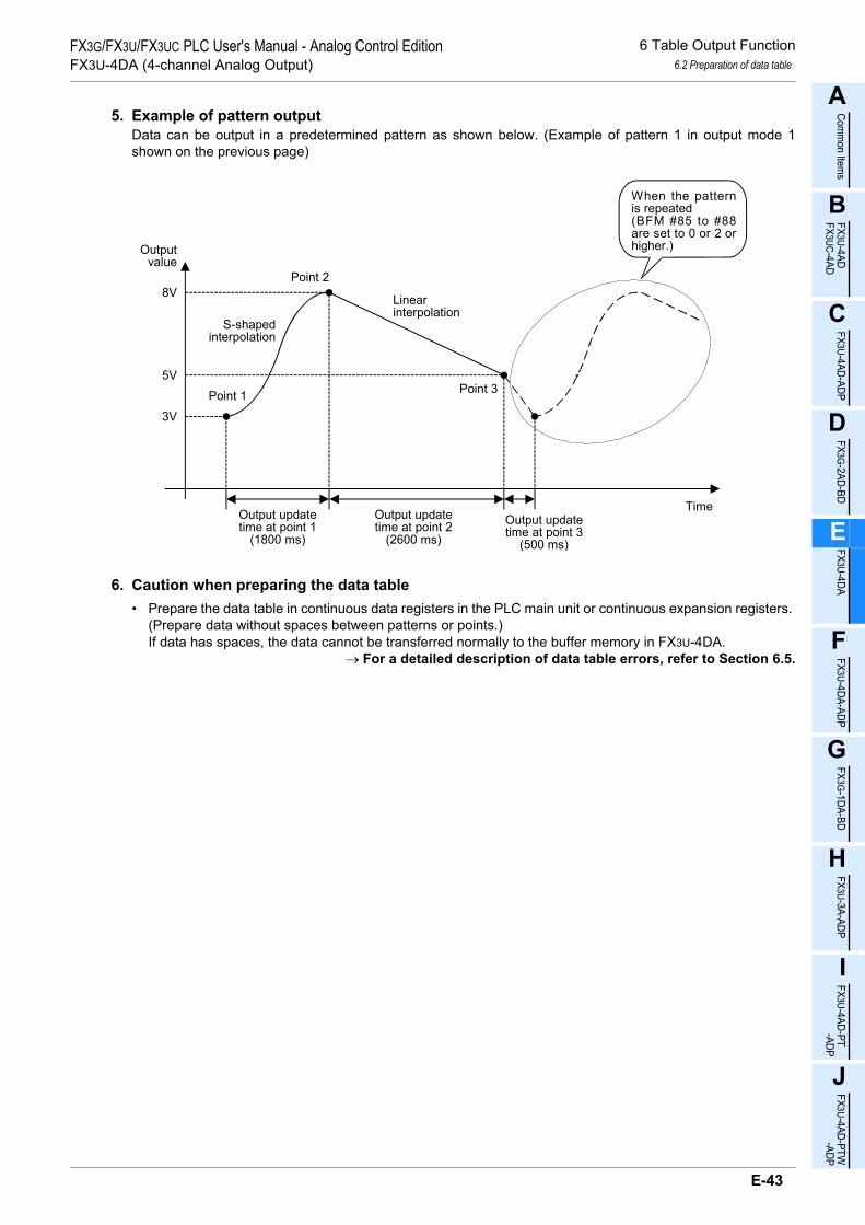
6 Table Output Function6.2 Preparation of data table
A
Comm
on Items
B
FX3U-4ADFX3UC-4AD
C
FX3U-4AD-ADP
D
FX3G-2AD-BD
E
FX3U-4DA
F
FX3U-4DA-ADP
G
FX3G-1DA-BD
H
FX3U-3A-ADP
I
FX3U-4AD-PT -ADP
J
FX3U-4AD-PTW -ADP
FX3G/FX3U/FX3UC PLC User's Manual - Analog Control EditionFX3U-4DA (4-channel Analog Output)
5. Example of pattern outputData can be output in a predetermined pattern as shown below. (Example of pattern 1 in output mode 1shown on the previous page)
6. Caution when preparing the data table• Prepare the data table in continuous data registers in the PLC main unit or continuous expansion registers.
(Prepare data without spaces between patterns or points.)If data has spaces, the data cannot be transferred normally to the buffer memory in FX3U-4DA.
→ For a detailed description of data table errors, refer to Section 6.5.
3V
5V
Outputvalue
8V
Output updatetime at point 1
(1800 ms)
Point 1
TimeOutput updatetime at point 2
(2600 ms)Output updatetime at point 3
(500 ms)
Point 2
Point 3
S-shapedinterpolation
Linearinterpolation
When the patternis repeated(BFM #85 to #88are set to 0 or 2 orhigher.)
E-43

6 Table Output Function6.3 Procedures for transferring data table to buffer memory
FX3G/FX3U/FX3UC PLC User's Manual - Analog Control EditionFX3U-4DA (4-channel Analog Output)
6.3 Procedures for transferring data table to buffer memory
The data table prepared in the data registers (D1000 to D7999) in the PLC or the expansion registers (R0 toR32767) are transferred to the buffer memory in FX3U-4DA.The transfer procedures are shown below.
1. Specify the head device number of the data table to be transferred. (BFM #98, initial value: K1000)Specify the head device number of the data table in BFM #98.The setting range is K1000 to K7994 for the data registers (D1000 to D7999) (because at least six points areoccupied) or K0 to K32762 for the expansion registers (R0 to R32767) (because at least six points areoccupied).
Example) When the data table is set starting from D1000, set K1000 in BFM #98.When a value out of the setting range is set, the error code K21 is stored in the table output error code BFM#90, the number of the buffer memory, K98, that has developed the table output error is stored in BFM #91,and b8 of the error status BFM #29 is turned on.
2. Start transferring the data table. (BFM #99, initial value: H0000)Transfer the data table from the PLC to the FX3U-4DA using the data table transfer command (BFM #99).
• Data table transfer command
• Register type
* When a value out of the setting range is set, the error code is stored in the table output error code BFM #90,the number of the buffer memory, K99, that has developed the table output error is stored in BFM #91, andb8 of the error status BFM #29 is turned on.
Example) When K1000 is written in the head device number of data table (BFM #98) and H0001 is writtenin the data table transfer command (BFM #99), the data table will be transferred from the dataregister D1000.
Set value Transfer command0 No processing1 Execution of transfer of data table
Other than above values Invalid*
Set value Register type
0 Transfer of data table from data registers (D1000 to 7999)
1 Transfer of data table from expansion registers (R0 to 32767)
Other than above values Invalid*
Invalid*Invalid*
Data table transfer commandRegister type
H
E-44

6 Table Output Function6.3 Procedures for transferring data table to buffer memory
A
Comm
on Items
B
FX3U-4ADFX3UC-4AD
C
FX3U-4AD-ADP
D
FX3G-2AD-BD
E
FX3U-4DA
F
FX3U-4DA-ADP
G
FX3G-1DA-BD
H
FX3U-3A-ADP
I
FX3U-4AD-PT -ADP
J
FX3U-4AD-PTW -ADP
FX3G/FX3U/FX3UC PLC User's Manual - Analog Control EditionFX3U-4DA (4-channel Analog Output)
3. Buffer memory contents in FX3U-4DA after transferThe transferred data table is stored in the following buffer memory areas.
BFM number Description
#100
Pattern 1
Number of points#101 Condition after output at final point in pattern#102
Point 1
Output data#103 Output update time
#104 Unit of output update time at each point, and point-to-point interpolation method
.
.
.
.
.
.
.
.
.#396
Point 99
Output data#397 Output update time
#398 Unit of output update time at each point, and point-to-point interpolation method
#399 Not used...
.
.
.
.
.
.#2800
Pattern 10
Number of points#2801 Condition after output at final point in pattern#2802
Point 1
Output data#2803 Output update time
#2804 Unit of output update time at each point, and point-to-point interpolation method
.
.
.
.
.
.
.
.
.#3096
Point 99
Output data#3097 Output update time
#3098 Unit of output update time at each point, and point-to-point interpolation method
E-45

6 Table Output Function6.3 Procedures for transferring data table to buffer memory
FX3G/FX3U/FX3UC PLC User's Manual - Analog Control EditionFX3U-4DA (4-channel Analog Output)
4. Example of transfer of data tableThe data table below shows the writing of K5000 to BFM#98 and H0001 to BFM#99. Data starting fromD5000 is transferred to the buffer memory in the FX3U-4DA.
PLC main unit FX3U-4DA
Data register Set value BFM number Set value Source data
registerD5000 K2
Transfer to buffer memory
#100 K3 D5001D5001 K3 #101 K0 D5002D5002 K0 #102 K3000 D5003D5003 K3000 #103 K18 D5004D5004 K18 #104 H0021 D5005D5005 H0021 #105 K8000 D5006D5006 K8000 #106 K26 D5007D5007 K26 #107 H0011 D5008D5008 H0011 #108 K5000 D5009D5009 K5000 #109 K5 D5010D5010 K5 #110 H0011 D5011D5011 H0011 :
: - -D5012 K4D5013 K1 #400 K4 D5012D5014 K2000 #401 K1 D5013D5015 K6 #402 K2000 D5014D5016 H0022 #403 K6 D5015D5017 K10000 #404 H0022 D5016D5018 K15 #405 K10000 D5017D5019 H0002 #406 K15 D5018D5020 K500 #407 H0002 D5019D5021 K45 #408 K500 D5020D5022 H0021 #409 K45 D5021D5023 K4000 #410 H0021 D5022D5024 K9 #411 K4000 D5023D5025 H0012 #412 K9 D5024
#413 H0012 D5025
E-46

6 Table Output Function6.3 Procedures for transferring data table to buffer memory
A
Comm
on Items
B
FX3U-4ADFX3UC-4AD
C
FX3U-4AD-ADP
D
FX3G-2AD-BD
E
FX3U-4DA
F
FX3U-4DA-ADP
G
FX3G-1DA-BD
H
FX3U-3A-ADP
I
FX3U-4AD-PT -ADP
J
FX3U-4AD-PTW -ADP
FX3G/FX3U/FX3UC PLC User's Manual - Analog Control EditionFX3U-4DA (4-channel Analog Output)
5. Cautions regarding data table transfer• While the table output function is executed, it is impossible to start transferring the data table.• The number of patterns is not transferred to the buffer memory in FX3U-4DA.• The transferred data table is stored in the buffer memory in FX3U-4DA. The data table stored in FX3U-4DA
will be erased when power is turned off. Therefore, it is necessary to transfer the data table after rebooting the power.
• At completion of transfer, BFM #99 will automatically change to H0000. Also when transfer is stopped due to an error, BFM #99 will automatically change to H0000. When BFM #99 changes to H0000, check the error flag.
→ For a detailed description of errors related to table output, refer to Subsection 6.5.• If an error occurs during transfer of the data table, the data up to the error is transferred. Subsequent data
is not transferred. • It is possible to write the data table directly in the buffer memory without using the data table transfer
command (BFM #99).In this case, the correctness of the data table is not evaluated until the table is output by the table output start/stop function (BFM #80).If a data table with incorrect data is output, the data up to the point where incorrect data occurs is output. At the point where incorrect data occurs, an error is registered and only the data output just before the occurrence of the error is held.
• Execute the data table transfer command (BFM #99) as a pulse execution type instruction.• During transfer of the data table, the scan time increases by up to about 10 ms.• The standard data table transfer time is obtained by the following formula.
Transfer time = (Scan time) ×
Number ofdata table items
64× (number of FX3U-4DA units connected to main unit)
* Fractions omittedExample)
• Scan time: 50 ms (including increase in scan time caused by data table transfer)• Number of data table items to be transferred: 2991 items (when the number of patterns is 10
and the number of points in each pattern is 99)• Number of units connected to FX3U-4DA: 8 units
Transfer time = (50 ms) ×2991
64× (8 units)
= 18800 ms
*
E-47

6 Table Output Function6.4 Procedures for executing table output function
FX3G/FX3U/FX3UC PLC User's Manual - Analog Control EditionFX3U-4DA (4-channel Analog Output)
6.4 Procedures for executing table output function
After setting the output patterns for the channels (BFM #81 to #84) and the number outputs for thechannels (BFM #85 to #88), turn on the table output function start/stop command (BFM #80) toexecute the table output function.
1. Set the output patterns for the channels. (BFM #81 to #84, initial value: K1)Set the output patterns for the channels in BFM #81 to #84.The output pattern can be changed in the middle of outputting the table.Setting range for BFM #81 to #84: 1 to 10When a value out of the setting range is set, the error code K31 is stored in the table output error code BFM#90, the number of the buffer memory (K81 to K84) that has developed the table output error is stored in BFM#91, and b8 of the error status BFM #29 is turned on.
2. Set the number of table outputs for the channels. (BFM #85 to #88, initial value: K0)Set the number of table outputs for the channels in BFM #85 to #88.The number of outputs can be changed even during outputting the table.Setting range for BFM #85 to #88: 0 to 32767When 0 is set, output of the table will be repeated until the table output is stopped by BFM #80.When a value out of the setting range is set, the error code K32 is stored in the table output error code BFM#90, the number of the buffer memory (K85 to K88) that has developed the table output error is stored in BFM#91, and b8 of the error status BFM #29 is turned on.
3. Table output start/stop (BFM #80, initial value: H0000)Table output is started and stopped by setting BFM #80 as shown below.
* When a value out of the setting range is set, the error code K33 is stored in the table output error code BFM#90, the number of the buffer memory (K80) that has developed the table output error is stored in BFM #91,and b8 of the error status BFM #29 is turned on.
Set value Description0 The table output function of each channel is stopped.
1The table output function of each channel is started.After output of the final point in the last cycle, 0 will beautomatically written.
Other than above values Invalid*
Hch4ch3 ch2
ch1
E-48

6 Table Output Function6.4 Procedures for executing table output function
A
Comm
on Items
B
FX3U-4ADFX3UC-4AD
C
FX3U-4AD-ADP
D
FX3G-2AD-BD
E
FX3U-4DA
F
FX3U-4DA-ADP
G
FX3G-1DA-BD
H
FX3U-3A-ADP
I
FX3U-4AD-PT -ADP
J
FX3U-4AD-PTW -ADP
FX3G/FX3U/FX3UC PLC User's Manual - Analog Control EditionFX3U-4DA (4-channel Analog Output)
4. Cautions regarding table output• When BFM #99 (data table transfer command) is not H0000, the table output function cannot be started.• When an error occurs during transfer of data table, start the table output after setting the correct data table.• While the table output completion flag BFM #89 is ON, output of a new table cannot be started.• The table output function is valid only while the PLC is in RUN mode.• While even a single channel is outputting data table (BFM #80 is not H0000), it is prohibited to change
BFM #0, #5, #9 to #17, #19, #20, #32 to #35, #38, #41 to 48, #50 to #54 and #60 to #63.• The pattern can be changed during output as shown below. (The change is invalid while the table output
completion flag BFM #89 is ON.)
5. Check the table output completion flag. (BFM #89, initial value: H0000)The value in BFM #89 indicates whether the table output from each channel has been completed.After data is output at the final point in the last cycle of a pattern, the table output completion flag is turned on.When the table output (BFM#80) is set to be stopped, the table output completion flag is turned off.
Value for each channel Table output completion flag
0 Table output uncompleted1 Table output completed
Outputvalue
Table output start
Pattern 1
Pattern 5
TimeChange from output pattern1 to output pattern 5
The data output in pattern 1 isignored, and data is output atpoint 1 in output pattern 5.
Hch4ch3 ch2
ch1
E-49

6 Table Output Function6.5 Details of table output error
FX3G/FX3U/FX3UC PLC User's Manual - Analog Control EditionFX3U-4DA (4-channel Analog Output)
6.5 Details of table output error
When an error related to the table output function occurs, the error code is stored in BFM #90, and the devicenumber or the buffer memory that has developed the error is stored in BFM #91.
1. Error code table and details of error source numbers
Error code (BFM #90) Details of error Table output error source number
(BFM #91)
K111The number of patterns in the data table that is held inthe PLC does not meet the following requirement.1 ≤ Number of patterns ≤ 10
Device number where the number ofpatterns is specified (same as the headdevice number in the data table)
K121The number of points in the data table that is held in thePLC does not meet the following requirement.1 ≤ Number of patterns ≤ 99
Device number where the number ofpatterns is specified
K122The number of points in the data table that is held in thebuffer memory does not meet the following requirement.1 ≤ Number of points ≤ 99
Number of BFM where the number ofpoints is specified
K131"The condition after output at final point in pattern"specified in the data table that is held in the PLC is not 0or 1.
Device number where "the condition afterthe final point output point in pattern" isspecified
K132"The condition after output at final point in pattern"specified in the data table that is held in the buffermemory is not 0 or 1.
Number of BFM where "the condition afteroutput point in the pattern" is specified
K151The output update time in the data table that is held in thePLC does not meet the following requirement.1 ≤ Output update time ≤ 32767
Device number where the output updatetime is specified
K152The output update time in the data table that is held in thebuffer memory does not meet the following requirement.1 ≤ Output update time ≤ 32767
Number of BFM where the output updatetime is specified
K161 The output update time unit in the data table that is heldin the PLC is not 0, 1, 2 or 3.
Device number where the output updatetime unit is specified
K162 The output update time unit in the data table that is heldin the buffer memory is not 0, 1, 2 or 3.
Number of BFM where the output updatetime unit is specified
K171 The interpolation method in the data table that is held inthe PLC is not 0, 1 or 2.
Device number where the interpolationmethod is specified
K172 The interpolation method in the data table that is held inthe buffer memory is not 0, 1 or 2.
Number of BFM where the interpolationmethod is specified
K21 The head device number BFM #98 in the data table to betransferred is out of the setting range. K98
K22 The value indicated by b0 to b3 of the transfer commandBFM #99 is not 0 or 1. K99
K23 The value indicated by b4 to b7 of the source registertype in BFM #99 is not 0 or 1. K99
K31Any of the output patterns BFM #81 to #84 does not meetthe following requirement.1 ≤ Output pattern ≤ 10
One of K81 to K84
K32The number of table outputs in BFM #85 to #88 does notmeet the following requirement.0 ≤ Number of repetitions of output ≤ 32767
One of K85 to K88
K33 The bit corresponding to each channel in the table outputstart/stop command in BFM #80 is not 0 or 1. K80
E-50

6 Table Output Function6.5 Details of table output error
A
Comm
on Items
B
FX3U-4ADFX3UC-4AD
C
FX3U-4AD-ADP
D
FX3G-2AD-BD
E
FX3U-4DA
F
FX3U-4DA-ADP
G
FX3G-1DA-BD
H
FX3U-3A-ADP
I
FX3U-4AD-PT -ADP
J
FX3U-4AD-PTW -ADP
FX3G/FX3U/FX3UC PLC User's Manual - Analog Control EditionFX3U-4DA (4-channel Analog Output)
2. Cautions regarding table output errors• Errors in data table
When the data table in the PLC contains an error, the error can be detected during transfer of the data to the buffer memory in FX3U-4DA. In this case, the error code (BFM #90) is K1 1, and the device number is written as the error source (BFM #91).If an error is caused in the data table by directly rewriting the data in BFM after the data table is transferred, the error can be detected when the table is output using incorrect data. In this case, the error code (BFM #90) is K1 2, and the BFM number is written as the error source (BFM #91).
• Error during transfer of the data tableWhile transferring of the data table, an error (error codes K31 to K33) does not occur even when the BFM #80 (table output function start/stop) is set to a value out of the setting range. An error occurs after the completion of the transfer of the data table.
• Error during output of the tableEven if the output value is scaled over during output of the table, the output of the table will not be stopped. However, while the output value is scaled over, b10 (scale over) of the error status BFM #29 stays on. When an error (error codes K122 to K172, K31 to K33) occurs during output of the table, the output of the table is cancelled and the analog output value just before the occurrence of the error is retained.
• Table output errors (BFM #90) and table output error source numbers (BFM #91) are not retained. They will be cleared when the next data table transfer command is given or the table output start function is executed.
E-51

6 Table Output Function6.6 Examples uses of table output function
FX3G/FX3U/FX3UC PLC User's Manual - Analog Control EditionFX3U-4DA (4-channel Analog Output)
6.6 Examples uses of table output function
[Uses of table output function]• Inverter frequency setting, servo speed control, etc.
1. Inverter frequency settingThe output frequency can be controlled by inputting analog signals (e.g. voltage from 0 to 10 V and currentfrom 4 to 20 mA) to inverter frequency setting signals.The analog signals and output signals have the following proportional relationship.
To control the frequency as shown below, where control the analog signal is proportional to the frequency usethe table output function.
Example of table output
10V5
60
30
Outputfrequency(Hz)
0
Analog signal
Time
60
30
0
Outputfrequency(Hz)
Time
10
5
0
Output updatetime at point 1
Point 1
Output updatetime at point 2
Output updatetime at point 3
Point 2 Point 3
Point 4
S-shapedinterpolation
No interpolation
Outputvoltage (V)
S-shapedinterpolation
E-52

7 Changing Output Characteristics7.1 Procedure for Changing Output Characteristics
A
Comm
on Items
B
FX3U-4ADFX3UC-4AD
C
FX3U-4AD-ADP
D
FX3G-2AD-BD
E
FX3U-4DA
F
FX3U-4DA-ADP
G
FX3G-1DA-BD
H
FX3U-3A-ADP
I
FX3U-4AD-PT -ADP
J
FX3U-4AD-PTW -ADP
FX3G/FX3U/FX3UC PLC User's Manual - Analog Control EditionFX3U-4DA (4-channel Analog Output)
7. Changing Output Characteristics
For FX3U-4DA, the standard output characteristics are provided for each output mode (BFM #0)at the time offactory shipment.Changing the offset data (BFM #10 to #13) and gain data (BFM #14 to #17) can change the outputcharacteristics of each channel. This chapter describes how to change the output characteristics.
7.1 Procedure for Changing Output Characteristics
1 Cancel the setting change prohibition mode.
If setting change is prohibited, write K3030 in BFM #19. The setting change prohibition mode willbe canceled.
2 Determine the output mode (BFM #0).
Determine the output mode (BFM #0) optimum for the selected channels and the voltage/currentspecifications.
Example: Enter "HFF00" in BFM to set output mode 0 for channels 1 and 2 and prevent use chan-nels 3 and 4
Cautions regarding data setting• If a value "1" or "4" is set for a channel, the output characteristics of the channel cannot be changed.• Set the optimum output mode for the analog signal to be output.
Set value (HEX) Output mode Analog output range Digital input range0 Voltage output mode -10V to +10V -32000 to +32000
1 Voltage output analog value mVspecification mode The characteristic cannot be changed.
2 Current output mode 0mA to 20mA 0 to 320003 Current output mode 4mA to 20mA 0 to 32000
4 Current output analog value µAspecification mode The characteristic cannot be changed.
5 to E Setting not allowed - -F Channel not used - -
E-53

7 Changing Output Characteristics7.1 Procedure for Changing Output Characteristics
FX3G/FX3U/FX3UC PLC User's Manual - Analog Control EditionFX3U-4DA (4-channel Analog Output)
3 Determine the output characteristics to be changed.
Example: Change to output voltage of 1 to 5 V with digital values 0 to 32000
4 Determine the offset data.
Determine the analog output value for the digital output value of 0.Set the analog output value in mV for the voltage output mode, and the analog output value in µAfor the current output mode.Example: To set the offset value of 1 V, set 1000 mV.
→ For a detailed description of the offset data, refer to Subsection 5.4.6.
5 Determine the gain data.
Determine the analog output value for the digital output value of 16000.Set the analog output value in mV for the voltage output mode, and the analog output value in µAfor the current output mode.
Example: To set the gain value of 3 V, set 3000 mV.(5-1)÷2+1 = 3V (3000 mV)
→ For a detailed description of the gain data, refer to Subsection 5.4.6.
Voltage output valueVoltage output value
+10V
+10.2V
-10.2V
-10V
-32000
+32000
0
0
Output mode: 0Output characteristics newly providedOutput characteristics provided at the time
of factory shipment
Digitalvalue
Digitalvalue
32000
5V
1V
E-54

7 Changing Output Characteristics7.1 Procedure for Changing Output Characteristics
A
Comm
on Items
B
FX3U-4ADFX3UC-4AD
C
FX3U-4AD-ADP
D
FX3G-2AD-BD
E
FX3U-4DA
F
FX3U-4DA-ADP
G
FX3G-1DA-BD
H
FX3U-3A-ADP
I
FX3U-4AD-PT -ADP
J
FX3U-4AD-PTW -ADP
FX3G/FX3U/FX3UC PLC User's Manual - Analog Control EditionFX3U-4DA (4-channel Analog Output)
6 Create a sequence program.
To change the output characteristics, write the offset data (BFM #10 to #13) and the gain data(BFM #14 to #17) in the sequence program, and then turn on the corresponding bit of BFM #9 forthe corresponding channel.
Example: Program for changing the output characteristics of channels 1 and 2 (For FX3U, FX3UCSeries PLCs):
7 Transfer the sequence program to change the output characteristics.
Transfer the sequence program, and start the PLC.
After the PLC is started and the output characteristic write command (X000) is turned on, the offsetdata and gain data will be written.
Since the offset data and gain data are stored in the EEPROM incorporated in FX3U-4DA, it is pos-sible to delete the pre-written sequence program.
8 Check the analog output signals
Check that the output analog signals correspond to the set output data.→ If analog signals are not correctly output, refer to Chapter 9 "Troubleshooting."
FNC 12 MOV
HFF00 U0\G0P
SET M0
M0
T0 FNC 16 FMOV
K1000 U0\G10 K2P
FNC 16 FMOV
K3000 U0\G14 K2P
FNC 12 MOV
H0003 U0\G9P
Output mode specification forchannels 1 to 4
Setting of offset data (channels 1 and 2)
K50T0
FNC 12 MOV
K3030 U0\G19P
X000
FNC 12 MOV
K0 U0\G19P
Cancellation of setting changeprohibition mode
Setting of gain data (channels 1 and 2)
Offset/gain setting value write command
Setting change prohibitionFNC 224K0 U0\G9
LD=
E-55

8 Examples of Practical Programs8.1 Example of Program for Analog Output Operation (Regular Operation)
FX3G/FX3U/FX3UC PLC User's Manual - Analog Control EditionFX3U-4DA (4-channel Analog Output)
8. Examples of Practical Programs
8.1 Example of Program for Analog Output Operation (Regular Operation)
When you want to use the initial output characteristics but do not need to use the status information, you canoperate the PLC with a simple program as shown below.
1. ConditionsThe sequence program described in this section is under the following conditions.1) System configuration
FX3U-4DA (unit No.0) should be connected to the FX3U Series PLC.2) Output mode
Channels 1 and 2 should be set to mode 0 (voltage output, -10 V to +10 V).Channel 3 should be set to mode 3 (current output, 4 mA to 20 mA).Channel 4 should be set to mode 2 (current output, 0 mA to 20 mA).
- For FX3U, FX3UC Series PLCs
- For FX3G, FX3U, FX3UC Series PLCs
M8002 FNC 12 MOV
H2300 U0\G0P
M8000K50T0
*
T0
Transfer H2300 to BFM #0 (output modes ofchannels 1 to 4).ch1 and ch2: Voltage output (-10 to +10 V),
output mode 0ch3: Current output (4 mA to 20 mA), output
mode 3ch4: Current output (0 mA to 20 mA), output
mode 2
Initial pulse
FNC 15 BMOV
D0 U0\G1 K4
RUN monitor
D0→BFM #1 (output to channel 1)D1→BFM #2 (output to channel 2)D2→BFM #3 (output to channel 3)D3→BFM #4 (output to channel 4)
Data to be output to channel 1 is written in D0.Data to be output to channel 2 is written in D1.Data to be output to channel 3 is written in D2.Data to be output to channel 4 is written in D3.
Store the data to be output to channels 1 to 4in D0 to D3 in the following ranges.D0 and D1: -32000 to +32000D2 and D3: 0 to 32000
* After setting the output mode, set the data writing time (waiting time) to 5 seconds or more for eachsetting. The specified output mode will be retained even if power failure occurs. After the output modeis specified, if the same output mode is used, it is not necessary to set the output mode and the waitingtime (T0 K50).
M8002
M8000K50T0
*
T0
Transfer H2300 to BFM #0 (output modes ofchannels 1 to 4).ch1 and ch2: Voltage output (-10 to +10 V),
output mode 0ch3: Current output (4 mA to 20 mA), output
mode 3ch4: Current output (0 mA to 20 mA), output
mode 2
Initial pulse
RUN monitor
D0→BFM #1 (output to channel 1)D1→BFM #2 (output to channel 2)D2→BFM #3 (output to channel 3)D3→BFM #4 (output to channel 4)
Data to be output to channel 1 is written in D0.Data to be output to channel 2 is written in D1.Data to be output to channel 3 is written in D2.Data to be output to channel 4 is written in D3.
Store the data to be output to channels 1 to 4in D0 to D3 in the following ranges.D0 and D1: -32000 to +32000D2 and D3: 0 to 32000
* After setting the output mode, set the data writing time (waiting time) to 5 seconds or more for eachsetting. The specified output mode will be retained even if power failure occurs. After the output modeis specified, if the same output mode is used, it is not necessary to set the output mode and the waitingtime (T0 K50).
FNC 79 TO
K0 K1P
K0 H2300
FNC 79 TO
K1 K4K0 D0
E-56

8 Examples of Practical Programs8.2 Example of Program using Useful Functions
A
Comm
on Items
B
FX3U-4ADFX3UC-4AD
C
FX3U-4AD-ADP
D
FX3G-2AD-BD
E
FX3U-4DA
F
FX3U-4DA-ADP
G
FX3G-1DA-BD
H
FX3U-3A-ADP
I
FX3U-4AD-PT -ADP
J
FX3U-4AD-PTW -ADP
FX3G/FX3U/FX3UC PLC User's Manual - Analog Control EditionFX3U-4DA (4-channel Analog Output)
8.2 Example of Program using Useful Functions
This section describes a practical program that uses the disconnection detection function (BFM #28), upper/lower limit function (BFM #38 to #48), corrective function by load resistance (BFM #50 to #54) and statusautomatic transfer function (BFM #60 to #63) of FX3U-4DA.
1. ConditionsThe sequence program described in this section is created under the following conditions.1) System configuration
FX3U-4DA (unit No.0) should be connected to the FX3U Series PLC.2) Output mode
Channels 1 and 2 should be set to mode 0 (voltage output, -10 V to +10 V).Channels 3 and 4 should be set to mode 2 (current output, 0 mA to 20 mA).
3) Convenient functionsThe disconnection detection function, upper/lower limit function, corrective function by load resistanceand status automatic transfer function are used.
4) Device assignment
Device Description
Input
X000 Clearance of upper/lower limit function status dataX001 Clearance of error status dataX002 Clearance of disconnection detection status dataD10 Data to be output from channel 1D11 Data to be output from channel 2D12 Data to be output from channel 3D13 Data to be output from channel 4
Output
Y000 Output of channel-1 lower limit error dataY001 Output of channel-1 upper limit error dataY002 Output of channel-2 lower limit error dataY003 Output of channel-2 upper limit error dataY004 Output of channel-3 lower limit error dataY005 Output of channel-3 upper limit error dataY006 Output of channel-4 lower limit error dataY007 Output of channel-4 upper limit error dataY010 Output of disconnection detection signalY011 Output of error detection signalD200 Data register at destination of automatic transfer of error status
D201 Data register at destination of automatic transfer of upper/lower limitfunction error status
D202 Data register at destination of automatic transfer of disconnection detectionerror status
E-57
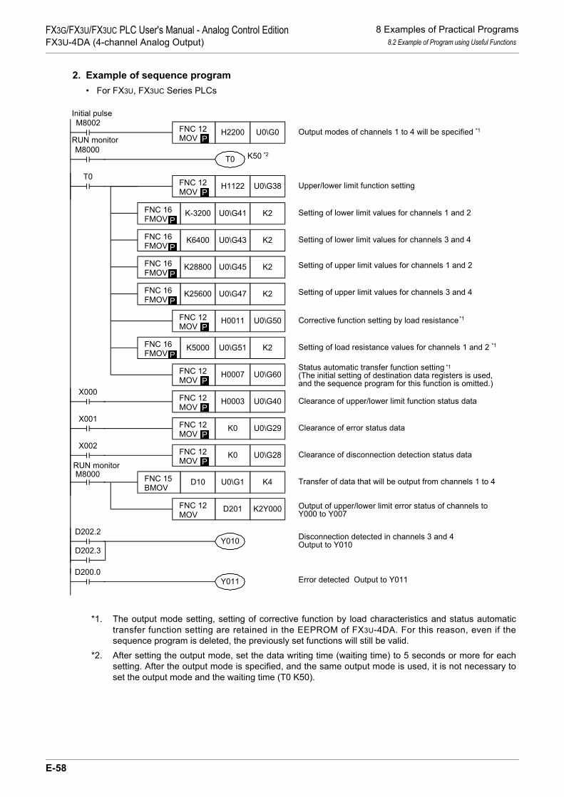
8 Examples of Practical Programs8.2 Example of Program using Useful Functions
FX3G/FX3U/FX3UC PLC User's Manual - Analog Control EditionFX3U-4DA (4-channel Analog Output)
2. Example of sequence program• For FX3U, FX3UC Series PLCs
*1. The output mode setting, setting of corrective function by load characteristics and status automatictransfer function setting are retained in the EEPROM of FX3U-4DA. For this reason, even if thesequence program is deleted, the previously set functions will still be valid.
*2. After setting the output mode, set the data writing time (waiting time) to 5 seconds or more for eachsetting. After the output mode is specified, and the same output mode is used, it is not necessary toset the output mode and the waiting time (T0 K50).
M8002 FNC 12 MOV
H2200 U0\G0P
M8000K50T0
T0
Output modes of channels 1 to 4 will be specified
Upper/lower limit function setting
Initial pulse
RUN monitor
FNC 12 MOV
H1122 U0\G38P
X000 FNC 12 MOV
H0003 U0\G40P
X001 FNC 12 MOV
K0 U0\G29P
X002 FNC 12 MOV
K0 U0\G28P
Clearance of upper/lower limit function status data
Clearance of disconnection detection status data
M8000RUN monitor
Output of upper/lower limit error status of channels toY000 to Y007
D202.3
Error detected Output to Y011D200.0
Y011
*1
FNC 16 FMOV
K-3200 U0\G41 K2P
FNC 16 FMOV
K6400 U0\G43 K2P
FNC 16 FMOV
K28800 U0\G45 K2P
FNC 16 FMOV
K25600 U0\G47 K2P
FNC 12 MOV
H0011 U0\G50P
FNC 16 FMOV
K5000 U0\G51 K2P
FNC 12 MOV
H0007 U0\G60P
FNC 15 BMOV
D10 U0\G1 K4
FNC 12 MOV
D201 K2Y000
D202.2Y010
Setting of lower limit values for channels 1 and 2
Setting of lower limit values for channels 3 and 4
Setting of upper limit values for channels 1 and 2
Setting of upper limit values for channels 3 and 4
Corrective function setting by load resistance
Setting of load resistance values for channels 1 and 2
Status automatic transfer function setting(The initial setting of destination data registers is used,and the sequence program for this function is omitted.)
Clearance of error status data
Disconnection detected in channels 3 and 4Output to Y010
Transfer of data that will be output from channels 1 to 4
*2
*1
*1
*1
E-58

8 Examples of Practical Programs8.2 Example of Program using Useful Functions
A
Comm
on Items
B
FX3U-4ADFX3UC-4AD
C
FX3U-4AD-ADP
D
FX3G-2AD-BD
E
FX3U-4DA
F
FX3U-4DA-ADP
G
FX3G-1DA-BD
H
FX3U-3A-ADP
I
FX3U-4AD-PT -ADP
J
FX3U-4AD-PTW -ADP
FX3G/FX3U/FX3UC PLC User's Manual - Analog Control EditionFX3U-4DA (4-channel Analog Output)
• For FX3G, FX3U, FX3UC Series PLCs
*1. The output mode setting, setting of corrective function by load characteristics and status automatictransfer function setting are retained in the EEPROM of FX3U-4DA. For this reason, even if thesequence program is deleted, the previously set functions will still be valid.
*2. After setting the output mode, set the data writing time (waiting time) to 5 seconds or more for eachsetting. After the output mode is specified, and the same output mode is used, it is not necessary toset the output mode and the waiting time (T0 K50).
M8002
M8000K50T0
T0
Output modes of channels 1 to 4 will be specified
Upper/lower limit function setting
Initial pulse
RUN monitor
X000
X001
X002
Clearance of upper/lower limit function status data
Clearance of disconnection detection status data
M8000RUN monitor
Output of upper/lower limit error status of channels toY000 to Y007
M23
Error detected Output to Y011M0
Y011
*1
M22Y010
Setting of lower limit values for channels 1 and 2
Setting of lower limit values for channels 3 and 4
Setting of upper limit values for channels 1 and 2
Setting of upper limit values for channels 3 and 4
Corrective function setting by load resistance
Setting of load resistance values for channels 1 and 2
Status automatic transfer function setting(The initial setting of destination data registers is used,and the sequence program for this function is omitted.)
Clearance of error status data
Disconnection detected in channels 3 and 4Output to Y010
Transfer of data that will be output from channels 1 to 4
*2
*1
*1
*1
FNC 79 TO
K0 K1P
K0 H2200
FNC 79 TO
K38 K1P
K0 H1122
FNC 79 TO
K41 K2P
K0 K-3200
FNC 79 TO
K45 K2P
K0 K28800
FNC 79 TO
K43 K2P
K0 K6400
FNC 79 TO
K47 K2P
K0 K25600
FNC 79 TO
K50 K1P
K0 H0011
FNC 79 TO
K51 K2P
K0 K5000
FNC 79 TO
K60 K1P
K0 H0007
FNC 79 TO
K40 K1P
K0 H0003
FNC 79 TO
K29 K1P
K0 K0
FNC 79 TO
K28 K1P
K0 K0
FNC 79 TO
K1 K4K0 D10
FNC 12 MOV
D201 K2Y000
FNC 12 MOV
D202 K4M20
FNC 12 MOV
D200 K4M0
E-59
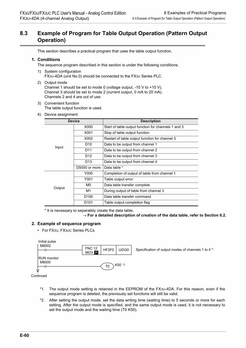
8 Examples of Practical Programs8.3 Example of Program for Table Output Operation (Pattern Output Operation)
FX3G/FX3U/FX3UC PLC User's Manual - Analog Control EditionFX3U-4DA (4-channel Analog Output)
8.3 Example of Program for Table Output Operation (Pattern Output Operation)
This section describes a practical program that uses the table output function.
1. ConditionsThe sequence program described in this section is under the following conditions.1) System configuration
FX3U-4DA (unit No.0) should be connected to the FX3U Series PLC.2) Output mode
Channel 1 should be set to mode 0 (voltage output, -10 V to +10 V).Channel 3 should be set to mode 2 (current output, 0 mA to 20 mA).Channels 2 and 4 are out of use.
3) Convenient functionThe table output function is used.
4) Device assignment
* It is necessary to separately create the data table.→ For a detailed description of creation of the data table, refer to Section 6.2.
2. Example of sequence program• For FX3U, FX3UC Series PLCs
*1. The output mode setting is retained in the EEPROM of the FX3U-4DA. For this reason, even if thesequence program is deleted, the previously set functions will still be valid.
*2. After setting the output mode, set the data writing time (waiting time) to 5 seconds or more for eachsetting. After the output mode is specified, and the same output mode is used, it is not necessary toset the output mode and the waiting time (T0 K50).
Device Description
Input
X000 Start of table output function for channels 1 and 3X001 Stop of table output functionX002 Restart of table output function for channel 3D10 Data to be output from channel 1D11 Data to be output from channel 2D12 Data to be output from channel 3D13 Data to be output from channel 4
D5000 or more Data table *
Output
Y000 Completion of output of table from channel 1Y001 Table output errorM0 Data table transfer completeM1 During output of table from channel 3
D100 Data table transfer commandD101 Table output completion flag
M8002 FNC 12 MOV
HF2F0 U0\G0P
M8000K50T0
Specification of output modes of channels 1 to 4
Initial pulse
RUN monitor
*1
*2
Continued
E-60

8 Examples of Practical Programs8.3 Example of Program for Table Output Operation (Pattern Output Operation)
A
Comm
on Items
B
FX3U-4ADFX3UC-4AD
C
FX3U-4AD-ADP
D
FX3G-2AD-BD
E
FX3U-4DA
F
FX3U-4DA-ADP
G
FX3G-1DA-BD
H
FX3U-3A-ADP
I
FX3U-4AD-PT -ADP
J
FX3U-4AD-PTW -ADP
FX3G/FX3U/FX3UC PLC User's Manual - Analog Control EditionFX3U-4DA (4-channel Analog Output)
* Execute the data table transfer command as a pulse execution type instruction.
FNC 12 MOV
K1 U0\G81P
T0Channel-1 output pattern
Number of repetitions of output of tablefrom channel 1
FNC 12 MOV
K2 U0\G83P
X000 FNC 12 MOV
H0101 U0\G80P
FNC 12 MOV
H0000 U0\G80P
Start table output function (channel 1)
Turning-off of M1 when output of table fromchannel 3 is stopped
Turning-on of M1 when table is output fromchannel 3
Completion of table output from channel 1Output to Y000
Y001
FNC 12 MOV
H0100 U0\G80P
D101.0Y000
Number of repetitions of output of tablefrom channel 3
Number of head device in data table
Data table transfer command
Readout of data table transfer command
Turning-on of M0 At the completion of transferof data table
Start table output function (channel 3)
Turning-on of M1 when table is output fromchannel 3
Stop table output function
Readout table output completion flag and tableoutput error
Restart of table output function (channel 3)
FNC 12 MOV
K5 U0\G85P
FNC 12 MOV
K0 U0\G87P
FNC 12 MOV
K5000 U0\G98P
FNC 12 MOV
H0001 U0\G99P
D100.0SET M0
FNC 79FROM
K0 K99 K1D100
SET M1
M1
M1
RST M1
FNC 12 MOV
H0100 U0\G80P
X002 M1
SET M1
FNC 79FROM
K0 K89 K2D101M1
FNC 228LD< >
K0 D102
Channel-3 output pattern
Output to Y001 when table output error occurs
X001
X000
*
E-61

8 Examples of Practical Programs8.3 Example of Program for Table Output Operation (Pattern Output Operation)
FX3G/FX3U/FX3UC PLC User's Manual - Analog Control EditionFX3U-4DA (4-channel Analog Output)
• For FX3G, FX3U, FX3UC Series PLCs
*1. The output mode setting is retained in the EEPROM of the FX3U-4DA. For this reason, even if thesequence program is deleted, the previously set functions will still be valid.
*2. After setting the output mode, set the data writing time (waiting time) to 5 seconds or more for eachsetting. After the output mode is specified, and the same output mode is used, it is not necessary toset the output mode and the waiting time (T0 K50).
*3. Execute the data table transfer command as a pulse execution type instruction.
T0Channel-1 output pattern
Number of repetitions of output of tablefrom channel 1
X000Start table output function (channel 1)
Turning-off of M1 when output of table fromchannel 3 is stopped
Turning-on of M1 when table is output fromchannel 3
Number of repetitions of output of tablefrom channel 3
Number of head device in data table
Data table transfer command
Readout of data table transfer command
Turning-on of M0 At the completion of transferof data table
Start table output function (channel 3)
Turning-on of M1 when table is output fromchannel 3
Stop table output function
Restart of table output function (channel 3)
M10SET M0
SET M1
M1
M1
RST M1
X002 M1
SET M1
Channel-3 output pattern
X001
X000
*3
M8002
M8000K50T0
Specification of output modes of channels 1 to 4
Initial pulse
RUN monitor
*1
*2
FNC 79 TO
K0 K1P
K0 HF2F0
FNC 79 TO
K81 K1P
K0 K1
FNC 79 TO
K83 K1P
K0 K2
FNC 79 TO
K85 K1P
K0 K5
FNC 79 TO
K87 K1P
K0 K0
FNC 79 TO
K98 K1P
K0 K5000
FNC 79 TO
K99 K1P
K0 H0001
FNC 78 FROM
K99 K1K0 D100
FNC 12 MOV
D100 K4M10
FNC 79 TO
K80 K1P
K0 H0100
FNC 79 TO
K80 K1P
K0 H0101
FNC 79 TO
K80 K1P
K0 H0000
FNC 79 TO
K80 K1P
K0 H0100
Continued
E-62

8 Examples of Practical Programs8.4 Program to Initialize FX3U-4DA (Factory Default)
A
Comm
on Items
B
FX3U-4ADFX3UC-4AD
C
FX3U-4AD-ADP
D
FX3G-2AD-BD
E
FX3U-4DA
F
FX3U-4DA-ADP
G
FX3G-1DA-BD
H
FX3U-3A-ADP
I
FX3U-4AD-PT -ADP
J
FX3U-4AD-PTW -ADP
FX3G/FX3U/FX3UC PLC User's Manual - Analog Control EditionFX3U-4DA (4-channel Analog Output)
8.4 Program to Initialize FX3U-4DA (Factory Default)
To initialize FX3U-4DA, execute the following program.This will return the output mode (BFM #0), the offset data (BFM #10 to #13) and the gain data (BFM #14 to#17) will be to the factory default status state.
1. ConditionsThe sequence program described in this section is under the following conditions.1) System configuration
FX3U-4DA (unit No.0) should be connected to the FX3U Series PLC.2) Device assignment
2. Example of sequence program• For FX3U, FX3UC Series PLCs
• For FX3G, FX3U, FX3UC Series PLCs
3. Cautions regarding initializing• During initialization, output is stopped, and H0000 is automatically written in the output status (BFM #6).
At the completion of initialization, the output status (BFM #6) will automatically change to H1111, and the output will be restarted.
• It takes approximately 5 seconds to complete initialization. Do not set (write) data in the buffer memory during the period.
• Priority is given to the setting of the change prohibition mode (BFM #19).• Once initialization is completed, the value in BFM #20 will automatically change to "K0".
Device DescriptionX000 4AD initialization command
Completion of table output from channel 1Output to Y000
Y001
M30Y000
Readout table output completion flag and tableoutput error
M1
FNC 228LD< >
K0 D102 Output to Y001 when table output error occurs
FNC 78 FROM
K89 K2K0 D101
FNC 12 MOV
D101 K4M30
X000 FNC 12 MOV
K1 U0\G20P
The 4DA will be initialized.(BFM #0 to #3098 will be cleared.)
4DA initialization command
X000The 4DA will be initialized.(BFM #0 to #3098 will be cleared.)
4DA initialization command
FNC 79 TO
K20 K1P
K0 K1
E-63

9 Troubleshooting9.1 PLC Version Number Check
FX3G/FX3U/FX3UC PLC User's Manual - Analog Control EditionFX3U-4DA (4-channel Analog Output)
9. Troubleshooting
This chapter describes the troubleshooting methods and error codes.If the D/A conversion data is not output, or if the proper digital value is not output, check the following items:• Wiring• Program• Error status
9.1 PLC Version Number Check
• Any versions (from Ver.2.20 (initial version) to the latest version) of the FX3U Series are compatible.• Check the version number of FX3UC Series. The version number should be 1.30 or later.• Any versions (from Ver.1.00 (initial version) to the latest version) of the FX3G Series are compatible.
→ For a detailed description of the version number check method, refer to Section 1.3.
9.2 Wiring Check
Check the wiring as follows:
1. PowerFX3U-4DA needs driving power. Verify that the power supply line is properly connected. Also check that the24 V indicator lamp of FX3U-4DA is on.
2. Analog output lineUse the 2-core twisted shielded cable for the analog output line. In addition, be sure to separate the analog output line from the other motive power lines or inductive lines.
→ For a detailed description of wiring, refer to Chapter 3.
9.3 Program Check
Check the program as follows:
1. Check the output mode and output data.Check that data has been set correctly in BFM #0 to #4.
2. Check the settings.Check that the offset data (BFM #10 to #13), gain data (BFM #14 to #17), upper/lower limit function setting(BFM #38) and table output function start/stop setting (BFM #80) are correct.
E-64
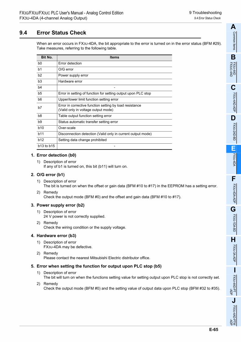
9 Troubleshooting9.4 Error Status Check
A
Comm
on Items
B
FX3U-4ADFX3UC-4AD
C
FX3U-4AD-ADP
D
FX3G-2AD-BD
E
FX3U-4DA
F
FX3U-4DA-ADP
G
FX3G-1DA-BD
H
FX3U-3A-ADP
I
FX3U-4AD-PT -ADP
J
FX3U-4AD-PTW -ADP
FX3G/FX3U/FX3UC PLC User's Manual - Analog Control EditionFX3U-4DA (4-channel Analog Output)
9.4 Error Status Check
When an error occurs in FX3U-4DA, the bit appropriate to the error is turned on in the error status (BFM #29).Take measures, referring to the following table.
1. Error detection (b0)1) Description of error
If any of b1 is turned on, this bit (b11) will turn on.
2. O/G error (b1)1) Description of error
The bit is turned on when the offset or gain data (BFM #10 to #17) in the EEPROM has a setting error.2) Remedy
Check the output mode (BFM #0) and the offset and gain data (BFM #10 to #17).
3. Power supply error (b2)1) Description of error
24 V power is not correctly supplied.2) Remedy
Check the wiring condition or the supply voltage.
4. Hardware error (b3)1) Description of error
FX3U-4DA may be defective.2) Remedy
Please contact the nearest Mitsubishi Electric distributor office.
5. Error when setting the function for output upon PLC stop (b5)1) Description of error
The bit will turn on when the functions setting value for setting output upon PLC stop is not correctly set.2) Remedy
Check the output mode (BFM #0) and the setting value of output data upon PLC stop (BFM #32 to #35).
Bit No. Itemsb0 Error detection
b1 O/G error
b2 Power supply error
b3 Hardware error
b4 -
b5 Error in setting of function for setting output upon PLC stop
b6 Upper/lower limit function setting error
b7 Error in corrective function setting by load resistance (Valid only in voltage output mode)
b8 Table output function setting error
b9 Status automatic transfer setting error
b10 Over-scale
b11 Disconnection detection (Valid only in current output mode)
b12 Setting data change prohibited
b13 to b15 -
E-65

9 Troubleshooting9.5 FX3U-4DA Initialization and Test Program
FX3G/FX3U/FX3UC PLC User's Manual - Analog Control EditionFX3U-4DA (4-channel Analog Output)
6. Upper/lower limit function value setting error (b6)1) Description of error
The bit will turn on when the setting value of the upper/lower limit function is not correctly set.2) Remedy
Check the output mode (BFM #0) and the lower limit (BFM #41 to 44) and upper limit (BFM #45 to #48)settings value of the upper/lower limit function.
7. Error in corrective function setting by load resistance (b7)1) Description of error
The bit will turn on when the setting value of the corrective function by load resistance is not correctly set.2) Remedy
Check the output mode (BFM #0) and the load resistance values (BFM #51 to #54) for the channels.
8. Table output function setting error (b8)1) Description of error
The bit will turn on when the setting value of the table output function is not correctly set.2) Remedy
Check the output mode (BFM #0) and the setting value of the table output function.
9. Status automatic transfer setting error (b9)1) Description of error
The bit will turn on when the setting value of the status automatic transfer function is not correctly set.2) Remedy
Check the setting values in the automatic transfer destination data register specification field (BFM #61 to#63).
10. Over-scale (b10)1) Description of error
This bit will turn on when analog output is out of the specified range.2) Remedy
Check the output mode (BFM #0) setting value and the values in the output data (BFM #1 to #4).
11. Disconnection detection (b11)1) Description of error
The bit is turned on when a cable is disconnected.2) Remedy
Check that no cables are disconnected or have contact failure.
12. Setting data change prohibited (b12)1) Description of error
The bit will turn on while the setting change is prohibited.2) Remedy
To change any setting, set BFM #19 to K3030.
9.5 FX3U-4DA Initialization and Test Program
If the above-mentioned remedies cannot solve the problem, initialize FX3U-4DA and then check theconditions of the FX3U-4DA using the test program.
→ For a detailed description of FX3U-4DA initialization program, refer to Subsection 8.4.→ For a detailed description of the test program, refer to Chapter 4.
E-66

A
Comm
on Items
B
FX3U-4ADFX3UC-4AD
C
FX3U-4AD-ADP
D
FX3G-2AD-BD
E
FX3U-4DA
F
FX3U-4DA-ADP
G
FX3G-1DA-BD
H
FX3U-3A-ADP
I
FX3U-4AD-PT -ADP
J
FX3U-4AD-PTW -ADP
FX3G/FX3U/FX3UC PLC User's Manual - Analog Control EditionFX3U-4DA-ADP (4-channel analog Output)
FX3G/FX3U/FX3UC Series Programmable Controllers
User's Manual [Analog Control Edition] FX3U-4DA-ADP (4-channel analog Output)
ForewordThis manual describes the specifications, wiring, and operation method for the FX3U-4DA-ADP special adapter (4-channel analog output) and should be read and understood before attempting to install or use the unit.Store this manual in a safe place so that you can take it out and read it whenever necessary. Always forward it to the end user.
© 2005 MITSUBISHI ELECTRIC CORPORATION
This manual confers no industrial property rights or any rights of any other kind, nor does it confer any patentlicenses. Mitsubishi Electric Corporation cannot be held responsible for any problems involving industrial propertyrights which may occur as a result of using the contents noted in this manual.
F-1

FX3G/FX3U/FX3UC PLC User's Manual - Analog Control EditionFX3U-4DA-ADP (4-channel analog Output)
F-2

1 Outline1.1 Outline of Functions
FX3G/FX3U/FX3UC PLC User's Manual - Analog Control EditionFX3U-4DA-ADP (4-channel analog Output)
A
Comm
on Items
B
FX3U-4ADFX3UC-4AD
C
FX3U-4AD-ADP
D
FX3G-2AD-BD
E
FX3U-4DA
F
FX3U-4DA-ADP
G
FX3G-1DA-BD
H
FX3U-3A-ADP
I
FX3U-4AD-PT -ADP
J
FX3U-4AD-PTW -ADP
1. Outline
This chapter outlines the FX3U-4DA-ADP (referred to as 4DA-ADP).
1.1 Outline of Functions
The FX3U-4DA-ADP is an analog special adapter. Which is connectable with the FX3U, FX3UC and FX3GSeries PLC to output the voltage/current data for up to 4 channels.1) Up to 4 units of 4DA-ADP can be connected to the FX3U/FX3UC Series PLC.
Up to 2*1 units of 4DA-ADP can be connected to the FX3G Series PLC.(Including other analog special adapters).
2) Either "voltage output" or "current output" can be specified for each channel.3) The D/A conversion results will be automatically output as the values to the special data register of the
FX3U/FX3UC/FX3G Series PLC.
Number of connectable
units
……For a detaileddescription of wiring,refer to Chapter 3.
……To check the connectablePLC model number, referto Section 1.3.
Point and section to bereferred to
System
……
Special devices ……For a detailed descriptionof special devices, refer toChapter 4.
For a detailed descriptionof a basic program, refer toSection 4.8.
Analog data
Refer to the system configuration shown in the User's Manual - Hardware Edition to check the number of connectable unitsand to configure the entire system.
*2. The expansion board is not required when connecting with the FX
For the FX3G Series PLC a connector conversion adapter is used.
3UC (D, DSS) PLC.
FX3U, FX3UC Series PLC : 4 maximum
FX3G Series PLC : 2*1 maximum(including other analog special adapters)
1st adapter M/D8260 to M/D8269
M/D8270 to M/D8279
M/D8280 to M/D8289
M/D8290 to M/D8299
2nd adapter
3rd adapter
4th adapter
++
Expansionboard*2
FX3U/FX3UC/FX3G Series PLC
For FX3U, FX3UC
Series PLC
Inverter, etc.
4thadapter
3rdadapter
2ndadapter
1stadapter
Contents
Output mode
switchingOutput setting data
Error status
Transfer direction
*1. Only 1 analog special adapter can be connected to the FX3G Series PLC(14-point and 24-point type).
F-3

1 Outline1.2 Setup Procedure Before Starting Operation
FX3G/FX3U/FX3UC PLC User's Manual - Analog Control EditionFX3U-4DA-ADP (4-channel analog Output)
1.2 Setup Procedure Before Starting Operation
Before starting analog output using the 4DA-ADP, follow the procedure below to set up the system:
Specifications:
• Operation environment
• Performance specifications
• Output characteristics
Specifications check
Refer to Chapter 2.
System configuration and selection
Wiring
Refer to Chapter 3.
FX3U-4DA-ADP
System configuration:
(Refer to the common pages for analog control.)
• Selection of units
Refer to the common
pages.
Wiring:
• Power supply line
• Analog output line
Outline of system:
• Compatible PLC version number
• Compatible programming tool version number
Outline
Refer to Chapter 1.
Programming
Refer to Chapter 4.
Programming:
• Details of special devices
• Examples of basic programs
Changing of output characteristics
Refer to Chapter 5.
Method of output characteristics change:
• Convenient function program
• How to use scaling instruction
If the error status data or the output analog value
is abnormal, refer to Chapter 6 "Troubleshooting."
F-4

1 Outline1.3 Connectable PLCs and Version Numbers
FX3G/FX3U/FX3UC PLC User's Manual - Analog Control EditionFX3U-4DA-ADP (4-channel analog Output)
A
Comm
on Items
B
FX3U-4ADFX3UC-4AD
C
FX3U-4AD-ADP
D
FX3G-2AD-BD
E
FX3U-4DA
F
FX3U-4DA-ADP
G
FX3G-1DA-BD
H
FX3U-3A-ADP
I
FX3U-4AD-PT -ADP
J
FX3U-4AD-PTW -ADP
1.3 Connectable PLCs and Version Numbers
The 4DA-ADP is compatible with the following PLCs.
*1. The FX3U/FX3UC Series PLC ver. 2.61 or later and FX3G Series PLC ver. 1.20 or later supportshardware error check.
→ For a detailed description of hardware error, refer to Section 6.5.
1. Version checkSpecial data register D8001 contains information for determining the PLC version number.
→ For a detailed description of the version check, refer to A. Common Items Subsection 5.1.2.
2. How to check the manufacturer's serial numberThe year and month of production of the product can be checked on the nameplate, and on the front of the product.
→ For a detailed description of how to check the manufacturer's serial number,refer to A. Common Items Subsection 5.1.1.
1.4 Compatible Programming Tool Version Number
Use the programming tool with the following version number to create programs for the 4DA-ADP of theFX3U/FX3UC/FX3G Series PLC:
1. GX Works2
2. GX Developer• FX3U/FX3UC Series PLC
• FX3G Series PLC
If a programming tool with the wrong version number is used, programming will not be possible.*2. For Ver. 8.13P to 8.24A of GX Developer, select FX3UC for the PLC type.
3. FX-30P
Compatible PLC Version number Date of production
FX3U Series PLC Ver.2.20 or later*1 After May 2005 (initial production)
FX3UC Series PLC Ver.1.20 or later*1 After April 2004
FX3G Series PLC Ver.1.00 or later*1 After June 2008 (initial production)
Software Version number RemarksGX Works2SW DNC-GXW2-J Ver. 1.07H or later -
GX Works2SW DNC-GXW2-E Ver. 1.08J or later -
Software Version number RemarksGX DeveloperSW D5C-GPPW-J Ver. 8.13P or later
When selecting the model, select FX3U(C)*2.GX DeveloperSW D5C-GPPW-E Ver. 8.18U or later
Software Version number RemarksGX Developer• SW D5C-GPPW-J• SW D5C-GPPW-E
Ver. 8.72A or later -
Model name Version number RemarksFX-30P Ver.1.00 or later -
F-5

2 Specifications2.1 Generic Specifications
FX3G/FX3U/FX3UC PLC User's Manual - Analog Control EditionFX3U-4DA-ADP (4-channel analog Output)
2. Specifications
This chapter describes the general, power supply, and performance specifications for 4DA-ADP.
2.1 Generic Specifications
*1. The criterion is shown in IEC61131-2.*2. If 4DA-ADP is connected to the FX3UC Series PLC, direct installation is not possible.
*3.
→ For a detailed description of the grounding, refer to Section 3.5.*4. If the pressure is higher than the atmospheric pressure, do not use 4DA-ADP.
The 4DA-ADP may malfunction.
Item SpecificationsAmbient temperature
0 to 55°C (32 to 131°F) when operating -25 to 75°C (-13 to 167°F) when stored
Relative humidity 5 to 95%RH (no condensation) when operating
Vibrationresistance*1
Frequency(Hz)
Acceleration(m/s2)
Half amplitude(mm)
10 times of testing in each direction (X-, Y-, and Z-axis directions) (Total: 80 min, each)
DIN Rail Mounting10 - 57 - 0.035
57 - 150 4.9 -
Direct Mounting*210 to 57 − 0.075
57 to 150 9.8 −
Shock resistance*1 147 m/s2 Acceleration, Action time: 11ms, 3 times by half-sine pulse in each direction X, Y, and Z
Noise resistance
Using noise simulator of:Noise voltage: 1,000Vp-p / Noise width: 1µs / Rise: 1ns / Cycle: 30 to 100Hz
Dielectric withstand voltage
500 V AC, for 1 minBetween all terminals and ground terminal
Insulation resistance
5MΩ or more using 500V DC insulation resistance meter
Grounding Class D grounding (grounding resistance: 100 Ω or less) <Common grounding with a heavy electrical system is not allowed.>*3
Workingenvironment Free from corrosive or flammable gas and excessive conductive dusts
Workingaltitude < 2000m*4
PLC OtherequipmentPLC Other
equipmentPLC Otherequipment
Shared groundingGood condition
Common groundingNot allowed
Independent groundingBest condition
F-6

2 Specifications2.2 Power Supply Specifications
FX3G/FX3U/FX3UC PLC User's Manual - Analog Control EditionFX3U-4DA-ADP (4-channel analog Output)
A
Comm
on Items
B
FX3U-4ADFX3UC-4AD
C
FX3U-4AD-ADP
D
FX3G-2AD-BD
E
FX3U-4DA
F
FX3U-4DA-ADP
G
FX3G-1DA-BD
H
FX3U-3A-ADP
I
FX3U-4AD-PT -ADP
J
FX3U-4AD-PTW -ADP
2.2 Power Supply Specifications
2.3 Performance Specifications
Item SpecificationsD/A conversion circuit driving power
24V DC +20%-15%, 150mA(It is necessary to connect a 24V DC power line to the terminal block.)
Interface driving power5V DC, 15mA(Since the internal power is supplied from the main unit of the FX Series, it is notnecessary to supply the power.)
ItemSpecifications
Voltage output Current outputAnalog output range
0V to 10 V DC(External load: 5kΩ to 1MΩ)
4mA to 20mA DC(External load: 500Ω or less)
Digital input 12 bits, binary
Resolution 2.5mV(10V/4000) 4µA(16mA/4000)
Total accuracy
• ±0.5% (±50mV) for 10V full scale(when ambient temperature is 25°C±5 °C)
• ±1.0% (±100mV) for 10V full scale(when ambient temperature is 0°C to 55°C)
If the external load resistance (Rs) is less than5kΩ, the value calculated from the followingformula will be added:(Addition will be 100mV per 1%.)
• ±0.5% (±80µA) for 16mA full scale(when ambient temperature is 25°C±5°C)
• ±1.0% (±160µA) for 16mA full scale(when ambient temperature is 0°C to 55 °C)
D/A conversion time
• FX3U/FX3UC Series PLC : 200µs (The data will be updated at every scan time.)• FX3G Series PLC : 250µs (The data will be updated at every scan time.)
→ For a detailed description of data update, refer to Section 2.4.
Outputcharacteristics
Insulation method• The photocoupler is used to insulate the analog output area from the PLC.• The DC/DC converter is used to insulate the power supply line from the analog output area.• Channels are not insulated from each other.
Numbers of I/O points occupied 0 point (This number is not related to the maximum number of input/output points of the PLC.)
Rs+47
47×100-0.9(%)
0
10V
4000 4080Digital input
Anal
og o
utpu
t
0 4000
20mA
Digital input
Anal
og o
utpu
t
4mA
4080
F-7

2 Specifications2.4 D/A Conversion Time
FX3G/FX3U/FX3UC PLC User's Manual - Analog Control EditionFX3U-4DA-ADP (4-channel analog Output)
2.4 D/A Conversion Time
This section describes the D/A conversion time.
2.4.1 When connected to a FX3U, FX3UC PLC
1. D/A conversion and special data register update timingD/A conversion is performed at every scan time of the PLC.During execution of the END instruction, the PLC writes the output setting data of the special data registers,performs D/A conversion of the data, and updates the analog output data.
2. D/A conversion during PLC stopIf the output holding function cancellation setting is disabled by the special device, the offset value will beoutput.If the output holding function cancellation setting is enabled, the output at switching from RUN to STOP will belatched.Just after power-on, however, the offset value will be output until operation begins.
3. If two or more analog special adapters are connectedDuring execution of the END instruction, data in all the connected adapters will be subject to D/A conversionand then output (in the order of 1st adapter → 2nd adapter... 4th adapter).
4. D/A conversion speed (data update time)During execution of END instruction, the output setting digital data per of 4 channel will be subject to D/Aconversion which takes 200µs, after which the analog data will be output.END instruction execution time will be "200µs × number of connected adapters."
FX3U/FX3UC Series PLCFX3U-4DA-ADP
1stFX3U-4DA-ADP
n'th
D/Aconversion
200µs/4ch
D/Aconversion
200µs/4ch
Digital valuewriting
D/A conversionstart command
END instruction
Sequenceprogram
Digital value writing
D/A conversionstart command
F-8

2 Specifications2.4 D/A Conversion Time
FX3G/FX3U/FX3UC PLC User's Manual - Analog Control EditionFX3U-4DA-ADP (4-channel analog Output)
A
Comm
on Items
B
FX3U-4ADFX3UC-4AD
C
FX3U-4AD-ADP
D
FX3G-2AD-BD
E
FX3U-4DA
F
FX3U-4DA-ADP
G
FX3G-1DA-BD
H
FX3U-3A-ADP
I
FX3U-4AD-PT -ADP
J
FX3U-4AD-PTW -ADP
2.4.2 When connected to a FX3G PLC
1. D/A conversion and special data register update timingD/A conversion is performed at every scan time of the PLC.During execution of the END instruction, the PLC writes the output setting data of the special data registers,performs D/A conversion of the data, and updates the analog output data.
2. D/A conversion during PLC stopIf the output holding function cancellation setting is disabled by the special device, the offset value will beoutput.If the output holding function cancellation setting is enabled, the output at switching from RUN to STOP will belatched.Just after power-on, however, the offset value will be output until operation begins.
3. If two analog special adapters are connectedDuring execution of the END instruction, data in all the connected adapters will be subject to D/A conversionand then output (in the order of 1st adapter → 2nd adapter).
4. D/A conversion speed (data update time)During execution of END instruction, the output setting digital data per of 4 channel will be subject to D/Aconversion which takes 250µs, after which the analog data will be output.END instruction execution time will be "250µs × number of connected adapters."
FX3G Series PLCFX3U-4DA-ADP
1stFX3U-4DA-ADP
2nd
D/Aconversion
250µs/4ch
D/Aconversion
250µs/4ch
Digital valuewriting
D/A conversionstart command
END instruction
Sequenceprogram
Digital value writing
D/A conversionstart command
F-9

3 WiringFX3G/FX3U/FX3UC PLC User's Manual - Analog Control EditionFX3U-4DA-ADP (4-channel analog Output)
3. Wiring
This chapter describes the 4DA-ADP wiring.Observe the following caution to wire the 4DA-ADP.
WIRING PRECAUTIONS
• Make sure to cut off all phases of the power supply externally before attempting wiring work.Failure to do so may cause electric shock or damages to the product.
WIRING PRECAUTIONS
• Connect the DC power supply wiring to the dedicated terminals described in this manual.If an AC power supply is connected to a DC input/output terminal or DC power supply terminal, the PLC will beburnt out.
• Do not wire vacant terminals externally.Doing so may damage the product.
• Perform class D grounding (grounding resistance: 100Ω or less) to the grounding terminal on the main unit.Do not use common grounding with heavy electrical systems.
• When drilling screw holes or wiring, make sure cutting or wire debris does not enter the ventilation slits.Failure to do so may cause fire, equipment failures or malfunctions.
• Make sure to observe the following precautions in order to prevent malfunctions under the influence of noise:- Do not bundle the power line or twisted shielded cable together with or lay it close to the main circuit, high-
voltage line, or load line.Otherwise, noise disturbance and/or surge induction are likely to take place. As a guideline, lay the control line at least 100mm (3.94") or more away from the main circuit, high-voltage line, or load line.
- Ground the shield of the analog input/output cable at one point on the signal receiving side. However, do not use common grounding with heavy electrical systems.
• Make sure to properly wire to the European terminal board in accordance with the following precautions.Failure to do so may cause electric shock, equipment failures, a short-circuit, wire breakage, malfunctions, ordamage to the product.- The disposal size of the cable end should follow the dimensions described in the manual.- Tightening torque should follow the specifications in the manual.- Twist the end of strand wire and make sure there are no loose wires. - Do not solder-plate the electric wire ends.- Do not connect more than the specified number of wires or electric wires of unspecified size.- Affix the electric wires so that neither the terminal block nor the connected parts are directly stressed.
F-10

3 Wiring3.1 Terminal Layout
FX3G/FX3U/FX3UC PLC User's Manual - Analog Control EditionFX3U-4DA-ADP (4-channel analog Output)
A
Comm
on Items
B
FX3U-4ADFX3UC-4AD
C
FX3U-4AD-ADP
D
FX3G-2AD-BD
E
FX3U-4DA
F
FX3U-4DA-ADP
G
FX3G-1DA-BD
H
FX3U-3A-ADP
I
FX3U-4AD-PT -ADP
J
FX3U-4AD-PTW -ADP
3.1 Terminal Layout
The terminals of the 4DA-ADP are arranged as follows:
Signal Application
External power
Channel 1 analog output
Channel 3 analog output
Channel 4 analog output
Channel 2 analog output
24+24-
I1+COM1V2+
I3+COM3V4+
COM4
V1+
I2+COM2V3+
I4+
Grounding terminal
24+
24-
VI+
I1+
CO
M1
V2+
I2+
CO
M2
V3+
I3+
CO
M3
V4+
I4+
CO
M4
FX3U-4DA-ADP
POWER
F-11
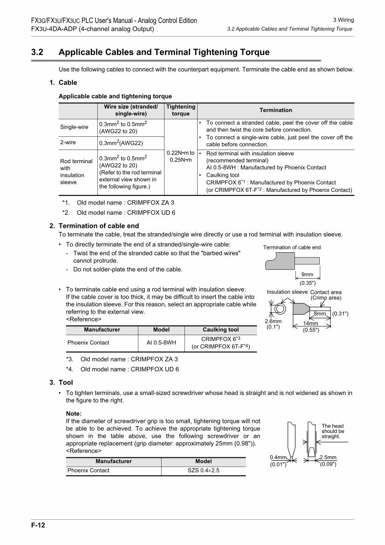
3 Wiring3.2 Applicable Cables and Terminal Tightening Torque
FX3G/FX3U/FX3UC PLC User's Manual - Analog Control EditionFX3U-4DA-ADP (4-channel analog Output)
3.2 Applicable Cables and Terminal Tightening Torque
Use the following cables to connect with the counterpart equipment. Terminate the cable end as shown below.
1. Cable
Applicable cable and tightening torque
*1. Old model name : CRIMPFOX ZA 3*2. Old model name : CRIMPFOX UD 6
2. Termination of cable endTo terminate the cable, treat the stranded/single wire directly or use a rod terminal with insulation sleeve.• To directly terminate the end of a stranded/single-wire cable:
- Twist the end of the stranded cable so that the "barbed wires" cannot protrude.
- Do not solder-plate the end of the cable.
• To terminate cable end using a rod terminal with insulation sleeve:If the cable cover is too thick, it may be difficult to insert the cable into the insulation sleeve. For this reason, select an appropriate cable while referring to the external view.<Reference>
*3. Old model name : CRIMPFOX ZA 3*4. Old model name : CRIMPFOX UD 6
3. Tool• To tighten terminals, use a small-sized screwdriver whose head is straight and is not widened as shown in
the figure to the right.
Note:If the diameter of screwdriver grip is too small, tightening torque will notbe able to be achieved. To achieve the appropriate tightening torqueshown in the table above, use the following screwdriver or anappropriate replacement (grip diameter: approximately 25mm (0.98")).<Reference>
Wire size (stranded/single-wire)
Tightening torque Termination
Single-wire 0.3mm2 to 0.5mm2
(AWG22 to 20)
0.22N•m to 0.25N•m
• To connect a stranded cable, peel the cover off the cableand then twist the core before connection.
• To connect a single-wire cable, just peel the cover off thecable before connection.2-wire 0.3mm2(AWG22)
Rod terminal withinsulation sleeve
0.3mm2 to 0.5mm2
(AWG22 to 20)(Refer to the rod terminal external view shown in the following figure.)
• Rod terminal with insulation sleeve(recommended terminal)AI 0.5-8WH : Manufactured by Phoenix Contact
• Caulking toolCRIMPFOX 6*1 : Manufactured by Phoenix Contact(or CRIMPFOX 6T-F*2 : Manufactured by Phoenix Contact)
Manufacturer Model Caulking tool
Phoenix Contact AI 0.5-8WH CRIMPFOX 6*3
(or CRIMPFOX 6T-F*4)
Manufacturer ModelPhoenix Contact SZS 0.4×2.5
9mm
Termination of cable end
(0.35")
8mm (0.31")
Contact area(Crimp area)
14mm2.6mm(0.1")
Insulation sleeve
(0.55")
0.4mm 2.5mm
The headshould bestraight.
(0.01") (0.09")
F-12

3 Wiring3.3 Power Supply Line
FX3G/FX3U/FX3UC PLC User's Manual - Analog Control EditionFX3U-4DA-ADP (4-channel analog Output)
A
Comm
on Items
B
FX3U-4ADFX3UC-4AD
C
FX3U-4AD-ADP
D
FX3G-2AD-BD
E
FX3U-4DA
F
FX3U-4DA-ADP
G
FX3G-1DA-BD
H
FX3U-3A-ADP
I
FX3U-4AD-PT -ADP
J
FX3U-4AD-PTW -ADP
3.3 Power Supply Line
Connect the 24V DC power supply line of the 4DA-ADP to the 24+ and 24- terminals of the terminal block.
3.3.1 To connect to the FX3G, FX3U Series PLC
Caution regarding connection of the power supply line:
• Ground the " " terminal to class-D grounded power supply line (100Ω or less) together with the grounding terminal of the PLC main unit.
• When using an external power supply, turn it ON at the same time with the main unit or earlier than the main unit. When turning OFF the power, confirm the safety of the system, and then turn OFF the power of the PLC (including special adapter) at the same time.
3.3.2 To connect to the FX3UC Series PLC
Caution regarding connection of the power supply line:• For the 24V DC power supply line, be sure to use the same power as the FX3UC Series PLC.
• Ground the " " terminal to a class-D grounded power supply line (100Ω or less) together with the grounding terminal of the PLC main unit.
24V DCClass-D
grounding
Terminalblock
4DA-ADP FX3G/FX3U
Series PLC(Main unit)15V
24+24-
1. To use an External power supply
Class-Dgrounding
Terminalblock
4DA-ADP
15V
24+24- 24V0V
2. To use the 24V DC power of the PLC
FX3G/FX3U
Series PLC(Main unit)
24V DCClass-D
grounding
Terminalblock
4DA-ADP
GreenRedBlack
FX3UC Series PLC(Main unit)
Powerconnector
24+24- 24+24- 24+24-
Powerconnector
Powercrossoverconnector
RedBlack
FX2NC Series PLC(Input extension
block)+15V
24+24-
F-13

3 Wiring3.4 Analog Output Line
FX3G/FX3U/FX3UC PLC User's Manual - Analog Control EditionFX3U-4DA-ADP (4-channel analog Output)
3.4 Analog Output Line
The analog output type, "voltage output" or "current output", can be selected for each channel.
*1. Use 2-core shielded twisted pair cable for the analog output lines, and separate the analog outputlines from other power lines or inductive lines.
*2. 24V DC service power supply of the FX3G/FX3U Series PLC can also be used.*3. Ground the shielded wire at one point on the signal receiving side.
3.5 Grounding
Grounding should be performed as stated below.• The grounding resistance should be 100Ω or less.• Independent grounding should be performed for best results.
When independent grounding is not performed, perform "shared grounding" as shown in the following figure.
→ For details, refer to User’s Manual - Hardware Edition of the PLC Series.
• The grounding wire size should be AWG22 to 20 (0.3 to 0.5 mm2).• The grounding point should be close to the PLC, and all grounding wires should be as short as possible.
ch
4DA-ADP
V+, I+, ch: represents the channel number.
Terminalblock
I+
COM
V+
I+
COM
V+
Class-Dgrounding
24+
24-24V DC
*1 Shielded
If voltage output is selected:
If current output is selected:
Connection of external powersupply line +15V
ch
*3
*2
*3
PLC OtherequipmentPLC Other
equipmentPLC Otherequipment
Shared groundingGood condition
Common groundingNot allowed
Independent groundingBest condition
F-14

4 Programming4.1 Writing of D/A Conversion Data
FX3G/FX3U/FX3UC PLC User's Manual - Analog Control EditionFX3U-4DA-ADP (4-channel analog Output)
A
Comm
on Items
B
FX3U-4ADFX3UC-4AD
C
FX3U-4AD-ADP
D
FX3G-2AD-BD
E
FX3U-4DA
F
FX3U-4DA-ADP
G
FX3G-1DA-BD
H
FX3U-3A-ADP
I
FX3U-4AD-PT -ADP
J
FX3U-4AD-PTW -ADP
4. Programming
This chapter describes how to create programs that can output the analog data using the 4DA-ADP.
4.1 Writing of D/A Conversion Data
1) The input digital data will be converted into analog data and then output to the terminals.2) If data is stored in the special devices, the averaging time can be set, and the output mode can be
specified.3) Special auxiliary relays (10 points) and special data registers (10 points) are assigned automatically
starting from the adapter nearest the main unit.→ For a detailed description of special device assignment, refer to Section 4.2.
• FX3U, FX3UC Series PLC
The analog special adapter nearest to the main unit is counted as the 1st analog special adapter, and the next adapter as the 2nd analog special adapter, and so on. In this case, however, do not include the high-speed input/output special adapter, communication special adapter, and the CF card special adapter.
Sequenceprogram
Special devices
D/A
D/A
D/A
D/A
Communi-cationspecialadapter
FX3U-4DA-ADP
FX3U-4DA-ADP
FX3U-4DA-ADP
FX3U-4DA-ADP FX3U/FX3UC Series PLC
1st2nd3rd4th
High-speedinput/output
specialadapter
Special auxiliary relays:M8280 to M8289
Special data registers:D8280 to D8289
Special auxiliary relays:M8270 to M8279
Special data registers:D8270 to D8279
Special auxiliary relays:M8260 to M8269
Special data registers:D8260 to D8269
Special auxiliary relays:M8290 to M8299
Special data registers:D8290 to D8299
F-15

4 Programming4.1 Writing of D/A Conversion Data
FX3G/FX3U/FX3UC PLC User's Manual - Analog Control EditionFX3U-4DA-ADP (4-channel analog Output)
• FX3G Series PLC
The analog special adapter nearest to the main unit is counted as the 1st analog special adapter, and the next adapter as the 2nd analog special adapter. In this case, however, do not include the connector conversion adapter and the communication special adapter.
*1. The second special adapter is not available in the FX3G Series PLC(14-point and 24-point type).
2nd*1 1st
Communi-
cation
special
adapter
Connector
conversion
adapter
Sequence
Program
FX3G Series PLC
Special devices
Special auxiliary relays:
M8280 to M8289
Special data registers:
D8280 to D8289
Special auxiliary relays:
M8290 to M8299
Special data registers:
D8290 to D8299
FX3U-4DA-ADP
FX3U-4DA-ADP
D/A
D/A
F-16

4 Programming4.2 List of Special Devices
FX3G/FX3U/FX3UC PLC User's Manual - Analog Control EditionFX3U-4DA-ADP (4-channel analog Output)
A
Comm
on Items
B
FX3U-4ADFX3UC-4AD
C
FX3U-4AD-ADP
D
FX3G-2AD-BD
E
FX3U-4DA
F
FX3U-4DA-ADP
G
FX3G-1DA-BD
H
FX3U-3A-ADP
I
FX3U-4AD-PT -ADP
J
FX3U-4AD-PTW -ADP
4.2 List of Special Devices
If 4DA-ADP is connected, special devices will be assigned automatically as shown in the following table:• FX3U, FX3UC Series PLC
R: Read / W: Write
Special device
Device numberDescription Attribute Reference
1st 2nd 3rd 4th
Special auxiliary
relay
M8260 M8270 M8280 M8290 Switches the output mode of channel 1. R/W
Section 4.3
M8261 M8271 M8281 M8291 Switches the output mode of channel 2. R/WM8262 M8272 M8282 M8292 Switches the output mode of channel 3. R/WM8263 M8273 M8283 M8293 Switches the output mode of channel 4. R/W
M8264 M8274 M8284 M8294 Sets the cancel of the channel-1 outputholding function. R/W
Section 4.4
M8265 M8275 M8285 M8295 Sets the cancel of the channel-2 outputholding function. R/W
M8266 M8276 M8286 M8296 Sets the cancel of the channel-3 outputholding function. R/W
M8267 M8277 M8287 M8297 Sets the cancel of the channel-4 outputholding function. R/W
M8268 to M8269
M8278 to M8279
M8288 to M8289
M8298 to M8299 Unused (Do not use.) - -
Special data
register
D8260 D8270 D8280 D8290 Channel-1 output setting data R/W
Section 4.5
D8261 D8271 D8281 D8291 Channel-2 output setting data R/WD8262 D8272 D8282 D8292 Channel-3 output setting data R/WD8263 D8273 D8283 D8293 Channel-4 output setting data R/W
D8264 to D8267
D8274 to D8277
D8284 to D8287
D8294 to D8297 Unused (Do not use.) - -
D8268 D8278 D8288 D8298 Error status R/W Section 4.6
D8269 D8279 D8289 D8299 Model code = 2 R Section 4.7
F-17

4 Programming4.3 Switching of Output Mode
FX3G/FX3U/FX3UC PLC User's Manual - Analog Control EditionFX3U-4DA-ADP (4-channel analog Output)
• FX3G Series PLCR: Read / W: Write
4.3 Switching of Output Mode
Turn the special auxiliary relay on/off to switch the output mode of 4DA-ADP between the current outputmode and the voltage output mode.To switch the output mode, use the following special auxiliary relays:• FX3U, FX3UC Series PLC
• FX3G Series PLC
Special deviceDevice number
Description Attribute Reference1st 2nd
Special auxiliary relay
M8280 M8290 Switches the output mode of channel 1. R/W
Section 4.3
M8281 M8291 Switches the output mode of channel 2. R/WM8282 M8292 Switches the output mode of channel 3. R/WM8283 M8293 Switches the output mode of channel 4. R/W
M8284 M8294 Sets the cancel of the channel-1 outputholding function. R/W
Section 4.4
M8285 M8295 Sets the cancel of the channel-2 outputholding function. R/W
M8286 M8296 Sets the cancel of the channel-3 outputholding function. R/W
M8287 M8297 Sets the cancel of the channel-4 outputholding function. R/W
M8288 to M8289
M8298 to M8299 Unused (Do not use.) - -
Special dataregister
D8280 D8290 Channel-1 output setting data R/W
Section 4.5
D8281 D8291 Channel-2 output setting data R/WD8282 D8292 Channel-3 output setting data R/WD8283 D8293 Channel-4 output setting data R/W
D8284 to D8287
D8294 to D8297 Unused (Do not use.) - -
D8288 D8298 Error status R/W Section 4.6
D8289 D8299 Model code = 2 R Section 4.7
Special auxiliary relayDescription
1st 2nd 3rd 4thM8260 M8270 M8280 M8290 Switches the output mode of channel 1
OFF:Voltage outputON :Current output
M8261 M8271 M8281 M8291 Switches the output mode of channel 2
M8262 M8272 M8282 M8292 Switches the output mode of channel 3
M8263 M8273 M8283 M8293 Switches the output mode of channel 4
Special auxiliary relayDescription
1st 2ndM8280 M8290 Switches the output mode of channel 1
OFF:Voltage outputON :Current output
M8281 M8291 Switches the output mode of channel 2
M8282 M8292 Switches the output mode of channel 3
M8283 M8293 Switches the output mode of channel 4
F-18

4 Programming4.4 Output Holding Function Cancellation Setting
FX3G/FX3U/FX3UC PLC User's Manual - Analog Control EditionFX3U-4DA-ADP (4-channel analog Output)
A
Comm
on Items
B
FX3U-4ADFX3UC-4AD
C
FX3U-4AD-ADP
D
FX3G-2AD-BD
E
FX3U-4DA
F
FX3U-4DA-ADP
G
FX3G-1DA-BD
H
FX3U-3A-ADP
I
FX3U-4AD-PT -ADP
J
FX3U-4AD-PTW -ADP
1. Program Example (For FX3U, FX3UC Series PLC)To switch the output mode of a channel, create a sequence program as follows:
4.4 Output Holding Function Cancellation Setting
This setting can hold the analog data output or to output the offset data (0V for voltage output mode, 4mA forcurrent output mode) when the PLC stops.To cancel or set the output holding function, use the following special auxiliary relays:• FX3U, FX3UC Series PLC
• FX3G Series PLC
1. Program Example (For FX3U, FX3UC Series PLC)To set or cancel the output holding function for a channel, create a sequence program as follows:
Special auxiliary relayDescription
1st 2nd 3rd 4th
M8264 M8274 M8284 M8294 Cancel output holding functionsetting for channel 1
OFF: Holds the analog data output just before stop of the PLC.
ON : Outputs the offset data at stop of the PLC.
M8265 M8275 M8285 M8295 Cancel output holding functionsetting for channel 2
M8266 M8276 M8286 M8296 Cancel output holding functionsetting for channel 3
M8267 M8277 M8287 M8297 Cancel output holding functionsetting for channel 4
Special auxiliary relayDescription
1st 2nd
M8284 M8294 Cancel output holding functionsetting for channel 1
OFF: Holds the analog data output just before stop of the PLC.
ON : Outputs the offset data at stop of the PLC.
M8285 M8295 Cancel output holding functionsetting for channel 2
M8286 M8296 Cancel output holding functionsetting for channel 3
M8287 M8297 Cancel output holding functionsetting for channel 4
1) To switch the channel output mode of channel 1 of the 1st analog special adapter to the voltage output mode:
M8001M8260
Normally OFF
2) To switch the output mode of channel 2 of the 1st analog special adapter to the current output mode:
M8000M8261
Normally ON
1) To set the output holding function for channel 1 of the 1st analog special adapter:
M8001M8264
Normally OFF
2) To cancel the output holding function for channel 2 of the 1st analog special adapter:
M8000M8265
Normally ON
F-19

4 Programming4.5 Output Setting Data
FX3G/FX3U/FX3UC PLC User's Manual - Analog Control EditionFX3U-4DA-ADP (4-channel analog Output)
4.5 Output Setting Data
Numeric data type: Decimal (K)The 4DA-ADP performs D/A conversion on the output setting data (digital data) into analog data, and outputsthe analog data.Use the special data registers shown in the following table for the output setting data:• FX3U, FX3UC Series PLC
• FX3G Series PLC
1. Program Example (For FX3U, FX3UC Series PLC)
Using the indicator or the sequence program, input the digital data to be subject to D/A conversion (to beoutput as analog data) in D100 and D101.
Special data registerDescription
1st 2nd 3rd 4thD8260 D8270 D8280 D8290 Channel-1 output setting data
D8261 D8271 D8281 D8291 Channel-2 output setting data
D8262 D8272 D8282 D8292 Channel-3 output setting data
D8263 D8273 D8283 D8293 Channel-4 output setting data
Special data registerDescription
1st 2ndD8280 D8290 Channel-1 output setting data
D8281 D8291 Channel-2 output setting data
D8282 D8292 Channel-3 output setting data
D8283 D8293 Channel-4 output setting data
M8000
Normally ON
FNC 12MOV
D100 D8260
FNC 12MOV
D101 D8261
Performs D/A conversion using the digitaldata stored in the D100 for channel 1 ofthe 1st analog special adapter.
Performs D/A conversion using the digitaldata stored in the D101 for channel 2 ofthe 1st analog special adapter.
F-20

4 Programming4.6 Error Status
FX3G/FX3U/FX3UC PLC User's Manual - Analog Control EditionFX3U-4DA-ADP (4-channel analog Output)
A
Comm
on Items
B
FX3U-4ADFX3UC-4AD
C
FX3U-4AD-ADP
D
FX3G-2AD-BD
E
FX3U-4DA
F
FX3U-4DA-ADP
G
FX3G-1DA-BD
H
FX3U-3A-ADP
I
FX3U-4AD-PT -ADP
J
FX3U-4AD-PTW -ADP
4.6 Error Status
1. Description of settingIf an error is detected on 4DA-ADP, the error status data will be stored in the corresponding special dataregister.The following table shows the special data registers that store the error status data:• FX3U, FX3UC Series PLC
• FX3G Series PLC
Check the ON/OFF status of each bit of the error status data register to check the description of the error.Errors are assigned to the bits as shown in the following table. Create a program to detect errors.
*1. The 4DA-ADP is supported from June, 2009 and later.For using the 4DA-ADP, it is necessary to use a main unit whose version supports this function.For the applicability of each combination of 4DA-ADP and main unit, refer to Section 6.5.
2. Program Example 1 (For FX3G, FX3U, FX3UC Series PLC)
*2. "1st" for the FX3G PLC.
Special data registerDescription
1st 2nd 3rd 4thD8268 D8278 D8288 D8298 Stores the error status data.
Special data registerDescription
1st 2ndD8288 D8298 Stores the error status data.
Bit Descriptionb0 Channel-1 output data setting error
b1 Channel-2 output data setting error
b2 Channel-3 output data setting error
b3 Channel-4 output data setting error
b4 EEPROM error
b5 Unused
b6 4DA-ADP hardware error (Power supply error included)*1
b7 to b15 Unused
Y000M0
Normally
ON
M1
M2
M3
M4
Y001
Y002
Y003
Y004
Channel-1 output data setting error in
Channel-2 output data setting error in
Channel-3 output data setting error in
Channel-4 output data setting error in
EEPROM error in the 3rd adapter
M8000MOV D8288 K4M0
3rd adapter.*2
3rd adapter.*2
3rd adapter.*2
3rd adapter.*2
*2
F-21

4 Programming4.6 Error Status
FX3G/FX3U/FX3UC PLC User's Manual - Analog Control EditionFX3U-4DA-ADP (4-channel analog Output)
3. Program Example 2 (For FX3U, FX3UC Series PLC)
Y000D8268.0
Y001D8268.1
Y002D8268.2
Y003D8268.3
Y004D8268.4
Channel-1 output data setting error in1st adapter
Channel-2 output data setting error in1st adapter
Channel-3 output data setting error in1st adapter
Channel-4 output data setting error in1st adapter
EEPROM error in 1st adapter
F-22

4 Programming4.7 Model Code
FX3G/FX3U/FX3UC PLC User's Manual - Analog Control EditionFX3U-4DA-ADP (4-channel analog Output)
A
Comm
on Items
B
FX3U-4ADFX3UC-4AD
C
FX3U-4AD-ADP
D
FX3G-2AD-BD
E
FX3U-4DA
F
FX3U-4DA-ADP
G
FX3G-1DA-BD
H
FX3U-3A-ADP
I
FX3U-4AD-PT -ADP
J
FX3U-4AD-PTW -ADP
4.7 Model Code
Initial value: K2Numeric data type: Decimal (K)
1. Description of settingWhen the 4DA-ADP is connected, model code "2" is stored in the corresponding special data register.The following table shows the special data registers that store the model code:• FX3U, FX3UC Series PLC
• FX3G Series PLC
Use the special data registers above to check whether 4DA-ADP is connected or not.
2. Program Example (For FX3U, FX3UC Series PLC)
4.8 Basic Program Example
Create the following basic program example to output D/A converted analog data.• For FX3G, FX3U, FX3UC Series PLCThe following program will set channel 1 of the 3rd*1 adapter to the voltage output mode and channel 2 tocurrent output mode, and will set digital data in D100 and D101 for D/A conversion.
Using the indicator or the sequence program, input the digital data to be subject to D/A conversion (to beoutput as analog data) in D100 and D101.
*1. "1st" for the FX3G PLC.
1st 2nd 3rd 4th DescriptionD8269 D8279 D8289 D8299 Model code
1st 2nd DescriptionD8289 D8299 Model code
FNC 224LD =
D8269 K2Checks the model codeof the 1st analog specialadapter.
Y007
M8001M8280
M8000M8281
Sets the output mode of channel 1 to the voltageoutput mode (0 V to 10 V).
Sets the output mode of channel 2 to the currentoutput mode (4 mA to 20 mA).
M8000FNC 12
MOVD100 D8280
FNC 12MOV
D101 D8281
Performs D/A conversion with the digital data storedin D100 for channel 1.
Performs D/A conversion with the digital data storedin D101 for channel 2.
M8284 Sets the output holding function for channel 1.
M8285 Cancels the output holding function for channel 2.
F-23

5 Changing of Output Characteristics5.1 Example: Changing of Voltage Output Characteristics
FX3G/FX3U/FX3UC PLC User's Manual - Analog Control EditionFX3U-4DA-ADP (4-channel analog Output)
5. Changing of Output Characteristics
Use the scaling instruction (SCL/FNC 259) for the FX3U/FX3UC Series PLC to change the outputcharacteristics.FX3G Series PLCs do not support the scaling instruction. Use sequence programs to change the outputcharacteristics.→ For a detailed description of scaling instruction, refer to the FX3G/FX3U/FX3UC Series Programming
Manual - Basic & Applied Instruction.
5.1 Example: Changing of Voltage Output Characteristics
This section describes an example of a program that can change the digital value range from 400 to 2000(when analog output range is 1 to 5V) to 0 to 10000.A specified digital value is inputted into D100.
1. Output characteristics
2. Example of program 1 (For FX3U, FX3UC Series PLC)• For example, create the following program to change the digital output of the 1st analog special adapter.
0 10000
Specifie
d d
igital outp
ut
valu
e t
o b
e a
ctu
ally
subje
ct
to D
/A c
onvers
ion
2000(5V)
400(1V)
Desired digital value (D100)
Voltage output characteristics(product specifications)
Digital value characteristicsto be changed
X-axis0 4000
10V
An
alo
g o
utp
ut
Digital value input400 2000
5V
1V
Y-axis
M8001M8260 Sets the output mode of channel 1 to the voltage output
mode.
M8002FNC 12
MOVK2 D50
FNC 12MOV
K0 D51
FNC 12MOV
K400 D52
FNC 12MOV
K10000 D53
FNC 12MOV
K2000 D54
M8000
Program for setting scaling instruction data table
The result of operation by scaling instruction will be storedin the D8260.
M8264 Sets the output holding function for channel 1.
ItemNumber of points
Startpoint
X-coordinate
Y-coordinate
Endpoint
X-coordinate
Y-coordinate
DescriptionSets the number of points.Digital value of specifiedstart point on X-axisDigital value of desired D/Aconversion start point
2Value Device
D50
0 D51
400 D52
Digital value of specified endpoint on X-axisDigital value of desired D/Aconversion end point
10000 D53
2000 D54
FNC 259SCL
D100 D50 D8260
F-24

5 Changing of Output Characteristics5.1 Example: Changing of Voltage Output Characteristics
FX3G/FX3U/FX3UC PLC User's Manual - Analog Control EditionFX3U-4DA-ADP (4-channel analog Output)
A
Comm
on Items
B
FX3U-4ADFX3UC-4AD
C
FX3U-4AD-ADP
D
FX3G-2AD-BD
E
FX3U-4DA
F
FX3U-4DA-ADP
G
FX3G-1DA-BD
H
FX3U-3A-ADP
I
FX3U-4AD-PT -ADP
J
FX3U-4AD-PTW -ADP
3. Example of program 2 (For FX3G Series PLC)• For example, create the following program to change the digital output data (D100) of the 1st analog
special adapter.
4. Cautions regarding programming• GX Developer version 8.13P or later supports scaling instruction (SCL/FNC259).• If the input digital value for the D/A conversion is out of the data table range specified by scaling instruction
(SCL/FNC259), the FX Series PLC will detect an operation error (error code: K6706).
Sets the output mode of channel 1 to the
voltage output mode.
D103 K400 D107 FNC 20
ADD
D101 K10000 D103 FNC 23
DDIV
D100 K1600 D101 FNC 22
MUL
M10
M8001M8280
FNC 12MOV
D107 D8280
M8284Sets the output holding function for
channel 1.
M10FNC 230LD>=
D100 K0 FNC 237AND<=
D100 K10000Check to make sure the digital
value (D100) is in range.
Calculation for changing output
characteristics.
Stores the operation result in D8280.
F-25

6 Troubleshooting6.1 PLC Version Number Check
FX3G/FX3U/FX3UC PLC User's Manual - Analog Control EditionFX3U-4DA-ADP (4-channel analog Output)
6. Troubleshooting
This chapter describes the troubleshooting methods and error status.If analog data is not output, or if the proper analog value is not output, check the following items:• Version number of PLC• Wiring• Special devices• Programs• Error status
6.1 PLC Version Number Check
• Any versions (from Ver.2.20 (initial version) to the latest version) of the FX3U Series are compatible.• Check the version number of FX3UC Series. The version number should be 1.20 or later.• Any versions (from Ver.1.00 (initial version) to the latest version) of the FX3G Series are compatible.
→ For a detailed description of the version number check method, refer to Section 1.3.
6.2 Wiring Check
Check the following items for wiring:
1. PowerThe 4DA-ADP needs driving power. Verify that the power supply line is properly connected. Also check thatthe POWER indicator lamp of the 4DA-ADP is on.
2. Analog output lineUse the 2-core twisted shielded pair cable for the analog output line. In addition, be sure to separate theanalog output line from other power lines or inductive lines.
→ For a detailed description of wiring, refer to Chapter 3.
6.3 Special Device Check
Check whether the special devices for the 4DA-ADP are being used correctly:
1. Output mode switchingVerify that the special device for switching the output mode is correctly set.Turn off the device to set the output mode to the voltage output mode. Turn on the device to set the outputmode to the current output mode.
2. Output setting dataCheck that the special device of the selected channel is correctly selected. This special device should beselected depending on the connected position and the channel.
3. Error statusCheck that no error is detected in the 4DA-ADP.If an error is detected, check the details of the error, and then check the wiring and programs.
→ For a detailed description of special devices, refer to Chapter 4.
F-26

6 Troubleshooting6.4 Program Check
FX3G/FX3U/FX3UC PLC User's Manual - Analog Control EditionFX3U-4DA-ADP (4-channel analog Output)
A
Comm
on Items
B
FX3U-4ADFX3UC-4AD
C
FX3U-4AD-ADP
D
FX3G-2AD-BD
E
FX3U-4DA
F
FX3U-4DA-ADP
G
FX3G-1DA-BD
H
FX3U-3A-ADP
I
FX3U-4AD-PT -ADP
J
FX3U-4AD-PTW -ADP
6.4 Program Check
Check the following items for the program:
1. Device for setting specified digital valueCheck that different values are not written to this device using other programs.
6.5 Error Status Check
If an error occurs in the 4DA-ADP, the corresponding bit will turn on.The bit which is turned ON due to the error status is held ON until overwritten to OFF by the program or thepower is cycled.
*1. The 4DA-ADP is supported from June, 2009 and later.For using the 4DA-ADP, it is necessary to use a main unit whose version supports this function.For the applicability of each combination of 4DA-ADP and main unit, refer to the table below.
For confirmation of the version of the main unit and checking the 4DA-ADP serial number, refer to thefollowing.
→ For details of confirmation of the PLC main unit version,refer to A. Common Items Subsection 5.1.2.
→ For details of check of the 4DA-ADP serial number,refer to A. Common Items Subsection 5.2.1.
To solve the problem, refer to the troubleshooting method described below:
1. Output data setting error (b0 to b3)1) Description of error
The specified digital value is outside the specified range.Analog data will not be correctly output.
2) RemedyCheck that the specified digital value is within the specified range.
2. EEPROM error (b4)1) Description of error
The adjustment data set in the EEPROM before delivery from our factory cannot be read out properly oris destroyed.
2) RemedyPlease contact the nearest Mitsubishi Electric distributor office.
Bit Descriptionb0 Channel-1 output data setting error
b1 Channel-2 output data setting error
b2 Channel-3 output data setting error
b3 Channel-4 output data setting error
b4 EEPROM error
b5 Unused
b6 4DA-ADP hardware error (Power supply error included)*1
b7 to b15 Unused
4DA-ADPyear and month of
production
FX3U, FX3UC Series PLC FX3G Series PLCFormer than
Ver.2.60 Ver.2.61 or later Former thanVer.1.10 Ver.1.20 or later
Former than2009 May Not applicable Not applicable Not applicable Not applicable
2009 Juneor later Not applicable Applicable Not applicable Applicable
F-27

6 Troubleshooting6.5 Error Status Check
FX3G/FX3U/FX3UC PLC User's Manual - Analog Control EditionFX3U-4DA-ADP (4-channel analog Output)
3. 4DA-ADP hardware error (b6)1) Description of error
The 4DA-ADP is not operating properly.2) Remedy
Check that the 24V DC power is properly supplied to the 4DA-ADP. Also check that the 4DA-ADP iscorrectly connected to the PLC.If the problem cannot be solved even after the above check, please contact the nearest MitsubishiElectric distributor office.
F-28

A
Comm
on Items
B
FX3U-4ADFX3UC-4AD
C
FX3U-4AD-ADP
D
FX3G-2AD-BD
E
FX3U-4DA
F
FX3U-4DA-ADP
G
FX3G-1DA-BD
H
FX3U-3A-ADP
I
FX3U-4AD-PT -ADP
J
FX3U-4AD-PTW -ADP
FX3G/FX3U/FX3UC PLC User's Manual - Analog Control EditionFX3G-1DA-BD (1-channel analog Output)
FX3G/FX3U/FX3UC Series Programmable Controllers
User's Manual [Analog Control Edition] FX3G-1DA-BD (1-channel analog Output)
ForewordThis manual describes the specifications, wiring, and operation method for the FX3G-1DA-BD analog output expansion board (1-channel analog output) and should be read and understood before attempting to install or use the unit.Store this manual in a safe place so that you can take it out and read it whenever necessary. Always forwardit to the end user.
© 2005 MITSUBISHI ELECTRIC CORPORATION
This manual confers no industrial property rights or any rights of any other kind, nor does it confer any patentlicenses. Mitsubishi Electric Corporation cannot be held responsible for any problems involving industrial propertyrights which may occur as a result of using the contents noted in this manual.
G-1

FX3G/FX3U/FX3UC PLC User's Manual - Analog Control EditionFX3G-1DA-BD (1-channel analog Output)
G-2

1 Outline1.1 Outline of Functions
FX3G/FX3U/FX3UC PLC User's Manual - Analog Control EditionFX3G-1DA-BD (1-channel analog Output)
A
Comm
on Items
B
FX3U-4ADFX3UC-4AD
C
FX3U-4AD-ADP
D
FX3G-2AD-BD
E
FX3U-4DA
F
FX3U-4DA-ADP
G
FX3G-1DA-BD
H
FX3U-3A-ADP
I
FX3U-4AD-PT -ADP
J
FX3U-4AD-PTW -ADP
1. Outline
This chapter outlines the FX3G-1DA-BD (referred to as 1DA-BD).
1.1 Outline of Functions
The FX3G-1DA-BD is an analog expansion board. Which is connectable with the FX3G Series PLC to outputthe voltage/current data for up to 1 channel.
1) Up to 2*1 units of 1DA-BD can be connected to the FX3G Series PLC.(Including other analog expansion boards, analog special adapters).
2) Either "voltage output" or "current output" can be specified.3) The D/A conversion results will be automatically output as the values to the special data register of the
FX3G Series PLC.
Number of connectable
units
……For a detaileddescription of wiring,refer to Chapter 3.
……To check the connectablePLC model number, referto Section 1.3.
Point and section to bereferred to
System
……
Special devices
……For a detailed descriptionof special devices, refer toChapter 4.
For a detailed descriptionof a basic program, refer toSection 4.8.
Analog data
Refer to the system configuration shown in the User's Manual - Hardware Edition to check the number of connectable unitsand to configure the entire system.
Board A M/D8260 to M/D8269
M/D8270 to M/D8279Board B
For FX3G Series PLC
FX3G Series PLC
Inverter, etc.
Contents
Output mode
switchingOutput setting data
Error status
Transfer direction
*1. Only 1 analog board can be connected to the FX3G Series PLC(14-point and 24-point type).
2*1 maximum
Connected to the option connector 2
Connected to the option connector 1
Board B Board A
including other analog expansion
boards, analog special adapters.( (
G-3
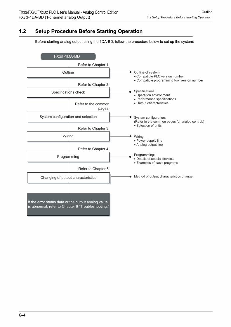
1 Outline1.2 Setup Procedure Before Starting Operation
FX3G/FX3U/FX3UC PLC User's Manual - Analog Control EditionFX3G-1DA-BD (1-channel analog Output)
1.2 Setup Procedure Before Starting Operation
Before starting analog output using the 1DA-BD, follow the procedure below to set up the system:
Specifications:
• Operation environment
• Performance specifications
• Output characteristics
Specifications check
Refer to Chapter 2.
System configuration and selection
Wiring
Refer to Chapter 3.
FX3G-1DA-BD
System configuration:
(Refer to the common pages for analog control.)
• Selection of units
Refer to the common
pages.
Wiring:
• Power supply line
• Analog output line
Outline of system:
• Compatible PLC version number
• Compatible programming tool version number
Outline
Refer to Chapter 1.
Programming
Refer to Chapter 4.
Programming:
• Details of special devices
• Examples of basic programs
Changing of output characteristics
Refer to Chapter 5.
Method of output characteristics change
If the error status data or the output analog value
is abnormal, refer to Chapter 6 "Troubleshooting."
G-4

1 Outline1.3 Connectable PLCs and Version Numbers
FX3G/FX3U/FX3UC PLC User's Manual - Analog Control EditionFX3G-1DA-BD (1-channel analog Output)
A
Comm
on Items
B
FX3U-4ADFX3UC-4AD
C
FX3U-4AD-ADP
D
FX3G-2AD-BD
E
FX3U-4DA
F
FX3U-4DA-ADP
G
FX3G-1DA-BD
H
FX3U-3A-ADP
I
FX3U-4AD-PT -ADP
J
FX3U-4AD-PTW -ADP
1.3 Connectable PLCs and Version Numbers
The 1DA-BD is compatible with the following PLC.
1. Version checkSpecial data register D8001 contains information for determining the PLC version number.
→ For a detailed description of the version check, refer to A.Common Items Subsection 5.1.2.
2. How to check the manufacturer's serial numberThe year and month of production of the product can be checked on the nameplate, and on the front of the product.
→ For a detailed description of how to check the manufacturer's serial number,refer to A.Common Items Subsection 5.1.1.
1.4 Compatible Programming Tool Version Number
Use the programming tool with the following version number to create programs for the 1DA-BD of the FX3GSeries PLC:
1. GX Works2
2. GX Developer
If a programming tool with the wrong version number is used, programming will not be possible.
3. FX-30P
Compatible PLC Version number Date of productionFX3G Series PLC Ver.1.10 or later After October 2008 (initial production)
Software Version number RemarksGX Works2SW DNC-GXW2-J Ver. 1.07H or later -
GX Works2SW DNC-GXW2-E Ver. 1.08J or later -
Software Version number RemarksGX Developer• SW D5C-GPPW-J• SW D5C-GPPW-E
Ver. 8.72A or later -
Model name Version number RemarksFX-30P Ver. 1.00 or later -
G-5

2 Specifications2.1 Generic Specifications
FX3G/FX3U/FX3UC PLC User's Manual - Analog Control EditionFX3G-1DA-BD (1-channel analog Output)
2. Specifications
This chapter describes the general and performance specifications for 1DA-BD.
2.1 Generic Specifications
*1. The criterion is shown in IEC61131-2.*2.
→ For a detailed description of the grounding, refer to Section 3.5.*3. If the pressure is higher than the atmospheric pressure, do not use 1DA-BD.
The 1DA-BD may malfunction.
Item SpecificationsAmbient temperature
0 to 55°C (32 to 131°F) when operating -25 to 75°C (-13 to 167°F) when stored
Relative humidity 5 to 95%RH (no condensation) when operating
Vibrationresistance*1
Frequency(Hz)
Acceleration(m/s2)
Half amplitude(mm)
10 times of testing in each direction (X-, Y-, and Z-axis directions) (Total: 80 min, each)
DIN Rail Mounting10 - 57 - 0.035
57 - 150 4.9 -
Direct Mounting10 to 57 − 0.075
57 to 150 9.8 −
Shock resistance*1 147 m/s2 Acceleration, Action time: 11ms, 3 times by half-sine pulse in each direction X, Y, and Z
Noise resistance
Using noise simulator of:Noise voltage: 1,000Vp-p / Noise width: 1µs / Rise: 1ns / Cycle: 30 to 100Hz
GroundingClass D grounding (grounding resistance: 100 Ω or less) <Common grounding with a heavy electrical system is not allowed.>*2
Workingenvironment Free from corrosive or flammable gas and excessive conductive dusts
Workingaltitude < 2000m*3
PLCOther
equipmentPLCOther
equipmentPLCOther
equipment
Shared groundingGood condition
Common groundingNot allowed
Independent groundingBest condition
G-6

2 Specifications2.2 Performance Specifications
FX3G/FX3U/FX3UC PLC User's Manual - Analog Control EditionFX3G-1DA-BD (1-channel analog Output)
A
Comm
on Items
B
FX3U-4ADFX3UC-4AD
C
FX3U-4AD-ADP
D
FX3G-2AD-BD
E
FX3U-4DA
F
FX3U-4DA-ADP
G
FX3G-1DA-BD
H
FX3U-3A-ADP
I
FX3U-4AD-PT -ADP
J
FX3U-4AD-PTW -ADP
2.2 Performance Specifications
ItemSpecifications
Voltage output Current outputAnalog output range
0V to 10 V DC(External load: 2kΩ to 1MΩ)
4mA to 20mA DC(External load: 500Ω or less)
Digital input 12 bits, binary 11 bits, binary
Resolution 2.5mV(10V/4000) 8µA(16mA/2000)
Total accuracy
• ±0.5% (±50mV) for 10V full scale(when ambient temperature is 25°C±5 °C)
• ±1.0% (±100mV) for 10V full scale(when ambient temperature is 0°C to 55°C)
Shipment adjustment is carried out by externalload resistance 2kΩ.If external load resistance becomes largerthan 2kΩ, the output voltage will increaseslightly.When the load is 1MΩ, the output voltagebecomes about 2% higher than the correctvalue.
• ±0.5% (±80µA) for 16mA full scale(when ambient temperature is 25°C±5°C)
• ±1.0% (±160µA) for 16mA full scale(when ambient temperature is 0°C to 55 °C)
D/A conversion time
60µs (The data will be updated at every scan time.)→ For a detailed description of data update, refer to Section 2.4.
Outputcharacteristics
Caution:An area of dead band is located in the regionof 0V. Therefore the output analog value maynot represent the digital value accurately.
Insulation method • The analog output area is not insulated from the PLC.
Numbers of I/O points occupied 0 point (This number is not related to the maximum number of input/output points of the PLC.)
0
10V
4000 4080Digital input
Analo
g o
utp
ut
0 2000
20mA
Digital input
Analo
g o
utp
ut
4mA
2040
G-7

2 Specifications2.3 D/A Conversion Time
FX3G/FX3U/FX3UC PLC User's Manual - Analog Control EditionFX3G-1DA-BD (1-channel analog Output)
2.3 D/A Conversion Time
This section describes the D/A conversion time.
1. D/A conversion and special data register update timingD/A conversion is performed at every scan time of the PLC.During execution of the END instruction, the PLC writes the output setting data of the special data registers,performs D/A conversion of the data, and updates the analog output data.
2. D/A conversion during PLC stopIf the output holding function cancellation setting is disabled by the special device, the offset value will beoutput.If the output holding function cancellation setting is enabled, the output at switching from RUN to STOP will belatched.Just after power-on, however, the offset value will be output until operation begins.
3. If two analog expansion boards are connectedDuring execution of the END instruction, data in all the connected boards will be subject to D/A conversionand then output (in the order of board A → board B).
4. D/A conversion speed (data update time)During execution of END instruction, the output setting digital data will be subject to D/A conversion whichtakes 60µs, after which the analog data will be output.END instruction execution time will be "60µs × number of connected board."
FX3G Series PLC
Sequence Program
END instruction
Board AFX3G-1DA-BD FX3G-1DA-BD
/1ch
60µs
/1ch
60µs
Board B
D/A conversion
start command
D/A
conversion
D/A
conversion
Digital value
writing
Digital value
writing
D/A conversion
start command
G-8
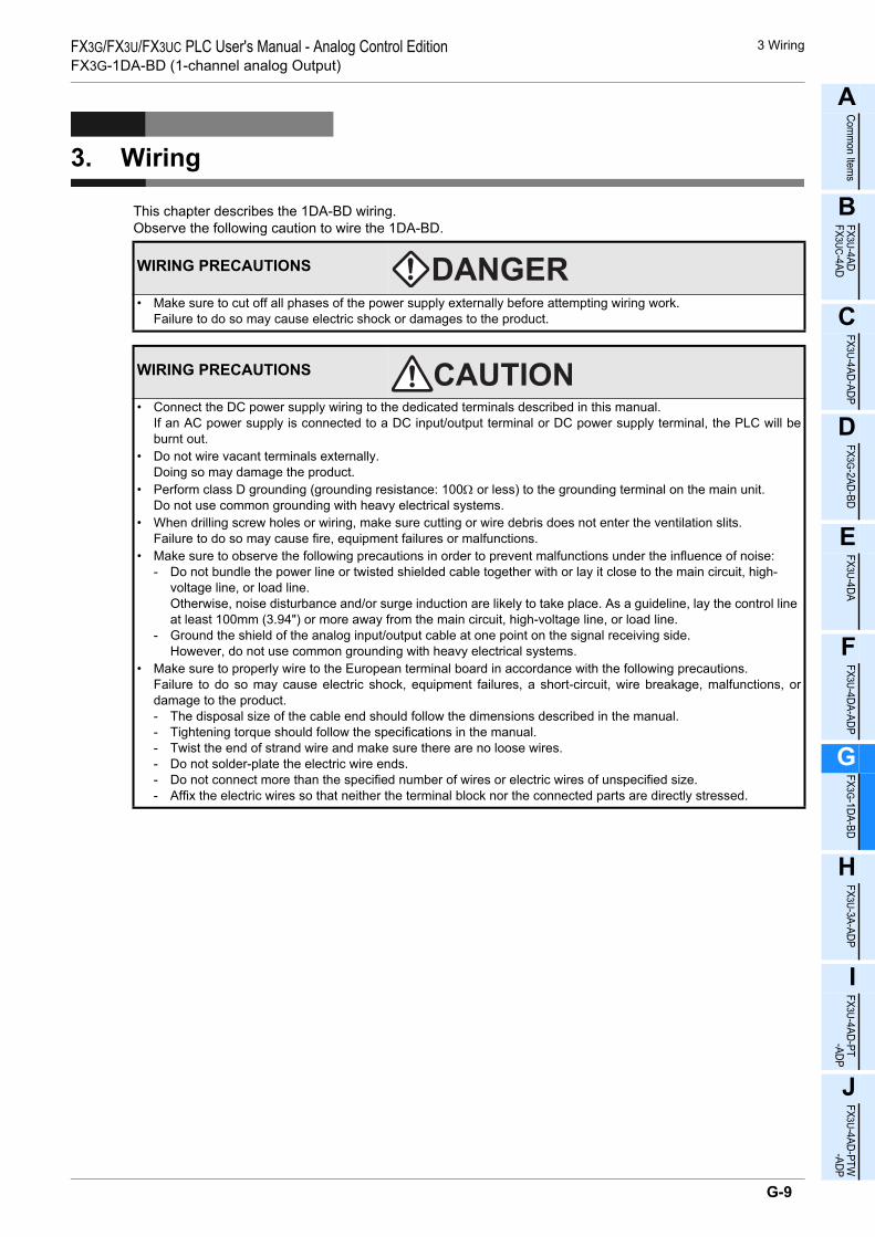
3 WiringFX3G/FX3U/FX3UC PLC User's Manual - Analog Control EditionFX3G-1DA-BD (1-channel analog Output)
A
Comm
on Items
B
FX3U-4ADFX3UC-4AD
C
FX3U-4AD-ADP
D
FX3G-2AD-BD
E
FX3U-4DA
F
FX3U-4DA-ADP
G
FX3G-1DA-BD
H
FX3U-3A-ADP
I
FX3U-4AD-PT -ADP
J
FX3U-4AD-PTW -ADP
3. Wiring
This chapter describes the 1DA-BD wiring.Observe the following caution to wire the 1DA-BD.
WIRING PRECAUTIONS
• Make sure to cut off all phases of the power supply externally before attempting wiring work.Failure to do so may cause electric shock or damages to the product.
WIRING PRECAUTIONS
• Connect the DC power supply wiring to the dedicated terminals described in this manual.If an AC power supply is connected to a DC input/output terminal or DC power supply terminal, the PLC will beburnt out.
• Do not wire vacant terminals externally.Doing so may damage the product.
• Perform class D grounding (grounding resistance: 100Ω or less) to the grounding terminal on the main unit.Do not use common grounding with heavy electrical systems.
• When drilling screw holes or wiring, make sure cutting or wire debris does not enter the ventilation slits.Failure to do so may cause fire, equipment failures or malfunctions.
• Make sure to observe the following precautions in order to prevent malfunctions under the influence of noise:- Do not bundle the power line or twisted shielded cable together with or lay it close to the main circuit, high-
voltage line, or load line.Otherwise, noise disturbance and/or surge induction are likely to take place. As a guideline, lay the control line at least 100mm (3.94") or more away from the main circuit, high-voltage line, or load line.
- Ground the shield of the analog input/output cable at one point on the signal receiving side. However, do not use common grounding with heavy electrical systems.
• Make sure to properly wire to the European terminal board in accordance with the following precautions.Failure to do so may cause electric shock, equipment failures, a short-circuit, wire breakage, malfunctions, ordamage to the product.- The disposal size of the cable end should follow the dimensions described in the manual.- Tightening torque should follow the specifications in the manual.- Twist the end of strand wire and make sure there are no loose wires. - Do not solder-plate the electric wire ends.- Do not connect more than the specified number of wires or electric wires of unspecified size.- Affix the electric wires so that neither the terminal block nor the connected parts are directly stressed.
G-9

3 Wiring3.1 Terminal Layout
FX3G/FX3U/FX3UC PLC User's Manual - Analog Control EditionFX3G-1DA-BD (1-channel analog Output)
3.1 Terminal Layout
The terminals of the 1DA-BD are arranged as follows:
Signal • • V+ I+ VI-
Application Unusedterminal
Outputterminal
COMterminal
G-10
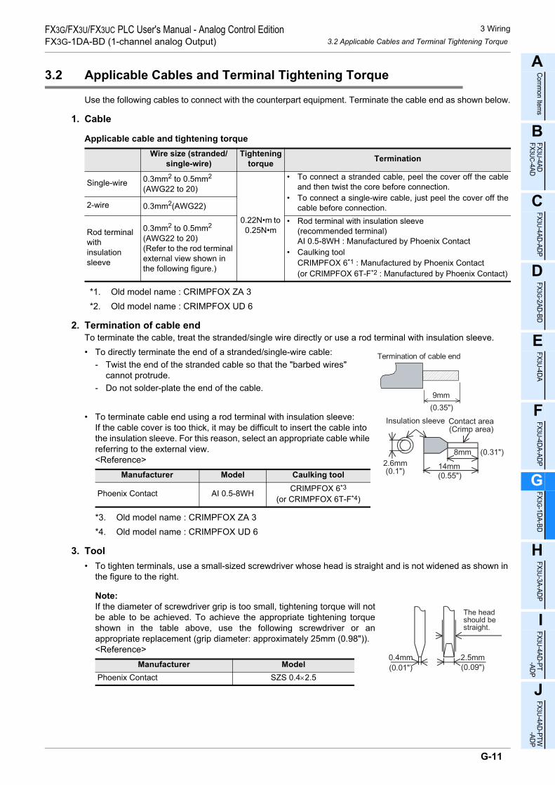
3 Wiring3.2 Applicable Cables and Terminal Tightening Torque
FX3G/FX3U/FX3UC PLC User's Manual - Analog Control EditionFX3G-1DA-BD (1-channel analog Output)
A
Comm
on Items
B
FX3U-4ADFX3UC-4AD
C
FX3U-4AD-ADP
D
FX3G-2AD-BD
E
FX3U-4DA
F
FX3U-4DA-ADP
G
FX3G-1DA-BD
H
FX3U-3A-ADP
I
FX3U-4AD-PT -ADP
J
FX3U-4AD-PTW -ADP
3.2 Applicable Cables and Terminal Tightening Torque
Use the following cables to connect with the counterpart equipment. Terminate the cable end as shown below.
1. Cable
Applicable cable and tightening torque
*1. Old model name : CRIMPFOX ZA 3*2. Old model name : CRIMPFOX UD 6
2. Termination of cable endTo terminate the cable, treat the stranded/single wire directly or use a rod terminal with insulation sleeve.• To directly terminate the end of a stranded/single-wire cable:
- Twist the end of the stranded cable so that the "barbed wires" cannot protrude.
- Do not solder-plate the end of the cable.
• To terminate cable end using a rod terminal with insulation sleeve:If the cable cover is too thick, it may be difficult to insert the cable into the insulation sleeve. For this reason, select an appropriate cable while referring to the external view.<Reference>
*3. Old model name : CRIMPFOX ZA 3*4. Old model name : CRIMPFOX UD 6
3. Tool• To tighten terminals, use a small-sized screwdriver whose head is straight and is not widened as shown in
the figure to the right.
Note:If the diameter of screwdriver grip is too small, tightening torque will notbe able to be achieved. To achieve the appropriate tightening torqueshown in the table above, use the following screwdriver or anappropriate replacement (grip diameter: approximately 25mm (0.98")).<Reference>
Wire size (stranded/single-wire)
Tightening torque Termination
Single-wire 0.3mm2 to 0.5mm2
(AWG22 to 20)
0.22N•m to 0.25N•m
• To connect a stranded cable, peel the cover off the cableand then twist the core before connection.
• To connect a single-wire cable, just peel the cover off thecable before connection.2-wire 0.3mm2(AWG22)
Rod terminal withinsulation sleeve
0.3mm2 to 0.5mm2
(AWG22 to 20)(Refer to the rod terminal external view shown in the following figure.)
• Rod terminal with insulation sleeve(recommended terminal)AI 0.5-8WH : Manufactured by Phoenix Contact
• Caulking toolCRIMPFOX 6*1 : Manufactured by Phoenix Contact(or CRIMPFOX 6T-F*2 : Manufactured by Phoenix Contact)
Manufacturer Model Caulking tool
Phoenix Contact AI 0.5-8WH CRIMPFOX 6*3
(or CRIMPFOX 6T-F*4)
Manufacturer ModelPhoenix Contact SZS 0.4×2.5
9mm
Termination of cable end
(0.35")
8mm (0.31")
Contact area(Crimp area)
14mm2.6mm(0.1")
Insulation sleeve
(0.55")
0.4mm 2.5mm
The headshould bestraight.
(0.01") (0.09")
G-11

3 Wiring3.3 Analog Output Line
FX3G/FX3U/FX3UC PLC User's Manual - Analog Control EditionFX3G-1DA-BD (1-channel analog Output)
3.3 Analog Output Line
*1. Use 2-core shielded twisted pair cable for the analog output lines, and separate the analog outputlines from other power lines or inductive lines.
*2. Ground the shielded wire at one point on the signal receiving side.
3.4 Grounding
Grounding should be performed as stated below.• The grounding resistance should be 100Ω or less.• Independent grounding should be performed for best results.
When independent grounding is not performed, perform "shared grounding" as shown in the following figure.
→ For details, refer to User’s Manual - Hardware Edition of the PLC Series.
• The grounding wire size should be AWG22 to 20 (0.3 to 0.5 mm2).• The grounding point should be close to the PLC, and all grounding wires should be as short as possible.
I+
VI-
V+
I+
VI-
V+
If voltage output is selected:
If current output is selected:
*1 Shield
Terminal1DA-BD
1DA-BD
block
Terminalblock
*1 Shield
*2 Class-Dgrounding
*2 Class-Dgrounding
PLCOther
equipmentPLCOther
equipmentPLCOther
equipment
Shared groundingGood condition
Common groundingNot allowed
Independent groundingBest condition
G-12

4 Programming4.1 Writing of D/A Conversion Data
FX3G/FX3U/FX3UC PLC User's Manual - Analog Control EditionFX3G-1DA-BD (1-channel analog Output)
A
Comm
on Items
B
FX3U-4ADFX3UC-4AD
C
FX3U-4AD-ADP
D
FX3G-2AD-BD
E
FX3U-4DA
F
FX3U-4DA-ADP
G
FX3G-1DA-BD
H
FX3U-3A-ADP
I
FX3U-4AD-PT -ADP
J
FX3U-4AD-PTW -ADP
4. Programming
This chapter describes how to create programs that can output the analog data using the 1DA-BD.
4.1 Writing of D/A Conversion Data
1) The input digital data will be converted into analog data and then output to the terminals.2) If data is stored in the special devices, the averaging time can be set, and the output mode can be
specified.3) Special auxiliary relays (10 points) and special data registers (10 points) are assigned respectively to the
analog expansion board (board A) connected to option connector 1 and the analog expansion board(board B) connected to option connector 2 in this order.
→ For a detailed description of special device assignment, refer to Section 4.2.• FX3G Series PLC
The analog expansion board connected to option connector 1 is regarded as the "board A", and the analog expansion board connected to option connector 2 is regarded as the "board B".
*1. Board B is not available in the FX3G Series PLC(14-point and 24-point type).
FX3G Series PLC
Sequence Program
Special auxiliary relays:M8260 to M8269 M8270 to M8279
D8260 to D8269 D8270 to D8279Special data register:
Board A
FX3G-1DA-BD
D/A D/A
FX3G-1DA-BD
Board B*1
Option connector 1 Option connector 2
Special data register:
Special auxiliary relays:
G-13

4 Programming4.2 List of Special Devices
FX3G/FX3U/FX3UC PLC User's Manual - Analog Control EditionFX3G-1DA-BD (1-channel analog Output)
4.2 List of Special Devices
If 1DA-BD is connected, special devices will be assigned automatically as shown in the following table:R: Read / W: Write
4.3 Switching of Output Mode
Turn the special auxiliary relay on/off to switch the output mode of 1DA-BD between the current output modeand the voltage output mode.To switch the output mode, use the following special auxiliary relays:
1. Program ExampleTo switch the output mode, create a sequence program as follows:
Special device
Device numberDescription Attribute Reference
Board A Board B
Special auxiliary
relay
M8260 M8270 Switches the output mode. R/W Section 4.3
M8261 to M8263
M8271 to M8273 Unused (Do not use.) - -
M8264 M8274 Sets the cancel of output holding function. R/W Section
4.4M8265 to
M8269M8275 to M8279 Unused (Do not use.) - -
Special data
register
D8260 D8270 Output setting data R/W Section 4.5
D8261 to D8267
D8271 to D8277 Unused (Do not use.) - -
D8268 D8278 Error status R/W Section 4.6
D8269 D8279 Model code = 4 R Section 4.7
Special auxiliary relayDescription
Board A Board B
M8260 M8270 Switches the output mode. OFF:Voltage outputON :Current output
To switch the channel output mode of theboard A to the voltage output mode:
M8001M8260
Normally OFF
G-14

4 Programming4.4 Output Holding Function Cancellation Setting
FX3G/FX3U/FX3UC PLC User's Manual - Analog Control EditionFX3G-1DA-BD (1-channel analog Output)
A
Comm
on Items
B
FX3U-4ADFX3UC-4AD
C
FX3U-4AD-ADP
D
FX3G-2AD-BD
E
FX3U-4DA
F
FX3U-4DA-ADP
G
FX3G-1DA-BD
H
FX3U-3A-ADP
I
FX3U-4AD-PT -ADP
J
FX3U-4AD-PTW -ADP
4.4 Output Holding Function Cancellation Setting
This setting can hold the analog data output or to output the offset data (0V for voltage output mode, 4mA forcurrent output mode) when the PLC stops.To cancel or set the output holding function, use the following special auxiliary relays:
1. Program ExampleTo set or cancel the output holding function, create a sequence program as follows:
4.5 Output Setting Data
Numeric data type: Decimal (K)The 1DA-BD performs D/A conversion on the output setting data (digital data) into analog data, and outputsthe analog data.Use the special data registers shown in the following table for the output setting data:
1. Program Example
Using the indicator or the sequence program, input the digital data to be subject to D/A conversion (to beoutput as analog data) in D100 and D101.
Special auxiliary relayDescription
Board A Board B
M8264 M8274 Cancel output holding function setting.
OFF: Holds the analog data output just before stop of the PLC.
ON : Outputs the offset data at stop of the PLC.
Special data registerDescription
Board A Board BD8260 D8270 Output setting data
To set the output holding function for the board A:
M8001M8264
Normally OFF
M8000
Normally ON
FNC 12MOV
D100 D8260
FNC 12MOV
D101 D8270
Performs D/A conversion using the digitaldata stored in the D100 for the board A.
Performs D/A conversion using the digitaldata stored in the D101 for the board B.
G-15

4 Programming4.6 Error Status
FX3G/FX3U/FX3UC PLC User's Manual - Analog Control EditionFX3G-1DA-BD (1-channel analog Output)
4.6 Error Status
1. Description of settingIf an error is detected on 1DA-BD, the error status data will be stored in the corresponding special dataregister.The following table shows the special data registers that store the error status data:
Check the ON/OFF status of each bit of the error status data register to check the description of the error.Errors are assigned to the bits as shown in the following table. Create a program to detect errors.
2. Program Example
4.7 Model Code
Initial value: K4Numeric data type: Decimal (K)
1. Description of settingWhen the 1DA-BD is connected, model code "4" is stored in the corresponding special data register.The following table shows the special data registers that store the model code:
Use the special data registers above to check whether 1DA-BD is connected or not.
2. Program Example
Special data registerDescription
Board A Board BD8268 D8278 Stores the error status data.
Bit Descriptionb0 Output data setting error
b1 to b3 Unused
b4 EEPROM error
b5 to b15 Unused
Special data registerDescription
Board A Board BD8269 D8279 Model code
Y000M0
Normally
ON
M4Y004
Output data setting error on
EEPROM error on the board A.
M8000 FNC 12
MOVD8268 K4M0
board A.
FNC 224LD =
D8269 K4Checks the model codeof the board A.Y007
G-16

4 Programming4.8 Basic Program Example
FX3G/FX3U/FX3UC PLC User's Manual - Analog Control EditionFX3G-1DA-BD (1-channel analog Output)
A
Comm
on Items
B
FX3U-4ADFX3UC-4AD
C
FX3U-4AD-ADP
D
FX3G-2AD-BD
E
FX3U-4DA
F
FX3U-4DA-ADP
G
FX3G-1DA-BD
H
FX3U-3A-ADP
I
FX3U-4AD-PT -ADP
J
FX3U-4AD-PTW -ADP
4.8 Basic Program Example
Create the following basic program example to output D/A converted analog data.The following program will set the board A to the voltage output mode and board B to current output mode,and will set digital data in D100 and D101 for D/A conversion.
Using the indicator or the sequence program, input the digital data to be subject to D/A conversion (to beoutput as analog data) in D100 and D101.
M8001
Normally
OFF
Normally
ON
M8260
M8000M8270
Sets the output mode of the board A to the voltageoutput mode (0 V to 10 V).
Sets the output mode of the board B to the currentoutput mode (4 mA to 20 mA).
M8000FNC 12
MOVD100 D8260
FNC 12MOV
D101 D8270
Performs D/A conversion with the digital data storedin D100 for the board A.
Performs D/A conversion with the digital data storedin D101 for the board B.
M8264 Sets the output holding function for the board A.
M8274 Cancels the output holding function for the board B.
G-17

5 Changing of Output Characteristics5.1 Example: Changing of Voltage Output Characteristics
FX3G/FX3U/FX3UC PLC User's Manual - Analog Control EditionFX3G-1DA-BD (1-channel analog Output)
5. Changing of Output Characteristics
The output characteristics can be changed using sequence programs in FX3G Series PLCs.
5.1 Example: Changing of Voltage Output Characteristics
This section describes an example of a program that can change the digital value range from 400 to 2000(when analog output range is 1 to 5V) to 0 to 10000.A specified digital value is inputted into D100.
1. Output characteristics
2. Example of programFor example, create the following program to change the digital output data (D100) of the board A.
0 10000
Specifie
d d
igital outp
ut
valu
e t
o b
e a
ctu
ally
subje
ct
to D
/A c
onvers
ion
2000(5V)
400(1V)
Desired digital value (D100)
Voltage output characteristics(product specifications)
Digital value characteristicsto be changed
X-axis0 4000
10V
An
alo
g o
utp
ut
Digital value input400 2000
5V
1V
Y-axis
D103 K400 D107FNC 20
ADD
D101 K10000 D103FNC 23
DDIV
D100 K1600 D101FNC 22
MUL
M10
M8001M8260
FNC 12MOV
D107 D8260
M8264
M10FNC 230
LD>=D100 K0 FNC 237
AND<=D100 K10000
Normally
OFF
Sets the output mode of 1st board
to the voltage output mode (0V to 10V).
Sets the output mode to the
output holding mode.
Check to make sure the digital
value (D100) is in range.
Calculation for changing output
characteristics.
Stores the operation result in D8260.
G-18
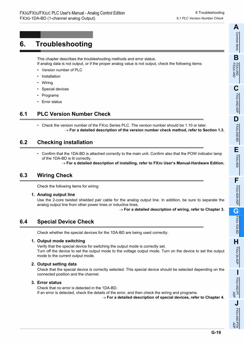
6 Troubleshooting6.1 PLC Version Number Check
FX3G/FX3U/FX3UC PLC User's Manual - Analog Control EditionFX3G-1DA-BD (1-channel analog Output)
A
Comm
on Items
B
FX3U-4ADFX3UC-4AD
C
FX3U-4AD-ADP
D
FX3G-2AD-BD
E
FX3U-4DA
F
FX3U-4DA-ADP
G
FX3G-1DA-BD
H
FX3U-3A-ADP
I
FX3U-4AD-PT -ADP
J
FX3U-4AD-PTW -ADP
6. Troubleshooting
This chapter describes the troubleshooting methods and error status.If analog data is not output, or if the proper analog value is not output, check the following items:• Version number of PLC• Installation• Wiring• Special devices• Programs• Error status
6.1 PLC Version Number Check
• Check the version number of the FX3G Series PLC. The version number should be 1.10 or later.→ For a detailed description of the version number check method, refer to Section 1.3.
6.2 Checking installation
• Confirm that the 1DA-BD is attached correctly to the main unit. Confirm also that the POW indicator lamp of the 1DA-BD is lit correctly.
→ For a detailed description of installing, refer to FX3G User’s Manual-Hardware Edition.
6.3 Wiring Check
Check the following items for wiring:
1. Analog output lineUse the 2-core twisted shielded pair cable for the analog output line. In addition, be sure to separate theanalog output line from other power lines or inductive lines.
→ For a detailed description of wiring, refer to Chapter 3.
6.4 Special Device Check
Check whether the special devices for the 1DA-BD are being used correctly:
1. Output mode switchingVerify that the special device for switching the output mode is correctly set.Turn off the device to set the output mode to the voltage output mode. Turn on the device to set the outputmode to the current output mode.
2. Output setting dataCheck that the special device is correctly selected. This special device should be selected depending on theconnected position and the channel.
3. Error statusCheck that no error is detected in the 1DA-BD.If an error is detected, check the details of the error, and then check the wiring and programs.
→ For a detailed description of special devices, refer to Chapter 4.
G-19

6 Troubleshooting6.5 Program Check
FX3G/FX3U/FX3UC PLC User's Manual - Analog Control EditionFX3G-1DA-BD (1-channel analog Output)
6.5 Program Check
Check the following items for the program:
1. Device for setting specified digital valueCheck that different values are not written to this device using other programs.
6.6 Error Status Check
If an error occurs in the 1DA-BD, the corresponding bit will turn on.The bit which is turned ON due to the error status is held ON until overwritten to OFF by the program or thepower is cycled.
To solve the problem, refer to the troubleshooting method described below:
1. Output data setting error (b0)1) Description of error
The specified digital value is outside the specified range.Analog data will not be correctly output.
2) RemedyCheck that the specified digital value is within the specified range.
2. EEPROM error (b4)1) Description of error
The adjustment data set in the EEPROM before delivery from our factory cannot be read out properly oris destroyed.
2) RemedyPlease contact the nearest Mitsubishi Electric distributor office.
Bit Descriptionb0 Output data setting error
b1 to b3 Unused
b4 EEPROM error
b5 to b15 Unused
G-20

A
Comm
on Items
B
FX3U-4ADFX3UC-4AD
C
FX3U-4AD-ADP
D
FX3G-2AD-BD
E
FX3U-4DA
F
FX3U-4DA-ADP
G
FX3G-1DA-BD
H
FX3U-3A-ADP
I
FX3U-4AD-PT -ADP
J
FX3U-4AD-PTW -ADP
FX3G/FX3U/FX3UC PLC User's Manual - Analog Control EditionFX3U-3A-ADP (2-channel analog Input, 1-channel analog output)
FX3G/FX3U/FX3UC Series Programmable Controllers
User's Manual [Analog Control Edition] FX3U-3A-ADP(2-channel analog Input, 1-channel analog output)
Foreword
This manual describes the specifications, wiring, and operation methods for the FX3U-3A-ADP analog special adapter (2-channel analog input, 1-channel analog output) and should be read and understood before attempting to install or use the unit.Store this manual in a safe place so that you can take it out and read it whenever necessary. Always forward it to the end user.
© 2005 MITSUBISHI ELECTRIC CORPORATION
This manual confers no industrial property rights or any rights of any other kind, nor does it confer any patentlicenses. Mitsubishi Electric Corporation cannot be held responsible for any problems involving industrial propertyrights which may occur as a result of using the contents noted in this manual.
H-1

FX3G/FX3U/FX3UC PLC User's Manual - Analog Control EditionFX3U-3A-ADP (2-channel analog Input, 1-channel analog output)
H-2

1 Outline1.1 Outline of Functions
FX3G/FX3U/FX3UC PLC User's Manual - Analog Control EditionFX3U-3A-ADP (2-channel analog Input, 1-channel analog output)
A
Comm
on Items
B
FX3U-4ADFX3UC-4AD
C
FX3U-4AD-ADP
D
FX3G-2AD-BD
E
FX3U-4DA
F
FX3U-4DA-ADP
G
FX3G-1DA-BD
H
FX3U-3A-ADP
I
FX3U-4AD-PT -ADP
J
FX3U-4AD-PTW -ADP
1. Outline
This chapter outlines the FX3U-3A-ADP (referred to as the 3A-ADP).
1.1 Outline of Functions
The analog special adapter FX3U-3A-ADP receives voltage/current data from 2 channels and outputs voltage/current data from 1 channel when connected to a FX3U/FX3UC/FX3G Series PLC.1) Up to 4 3A-ADP units can be connected to the FX3U/FX3UC Series PLC.
Up to 2*1 3A-ADP units can be connected to the FX3G Series PLC.(including the other analog special adapters).
2) The 3A-ADP receives and outputs voltage/current data.3) A/D conversion data of each channel will be automatically written to the special data register of the FX3U/
FX3UC/FX3G Series PLC.4) D/A conversion results will be automatically output as the values to the special data register of the FX3U/
FX3UC/FX3G Series PLC.
4thadapter
Number of connectable
units
……For a detaileddescription of wiring,refer to Chapter 3.
……To check the connectablePLC model number, referto Section 1.3.
Point and section to bereferred to
System
……
Special devices …… For a detailed descriptionof special devices, refer toChapter 4.
For a detailed descriptionof a basic program, refer toSection 4.12.
Refer to the system configuration shown in the User's Manual - Hardware Edition to check the number of connectable unitsand to configure the entire system.
Transfer directionContents
•Analog data•Error status
•Switching of input mode•Setting of averaging time•Output mode switching•Output setting data•Setting whether or not a channel is used
(including other analog special adapters)
3rdadapter
2ndadapter
1stadapter
1st adapter M/D8260 to M/D8269
M/D8270 to M/D8279
M/D8280 to M/D8289
M/D8290 to M/D8299
2nd adapter
3rd adapter
4th adapter
++
Expansion board*2
FX3U/FX3UC Series PLC
FX3U/FX3UC Series PLC : 4 maximum
FX3G Series PLC : 2 maximum*1
/FX3G
For FX3U/FX3UC
Series PLC
*1.Only 1 analog special adapter can be connected to the FX3G Series PLC(14-point and 24-point type).
*2.The expansion board is not required when connecting with the FX3UC (D, DSS) PLC.For the FX3G Series PLC a connector conversion adapter is used.
Analog data
Flowmeter,pressure sensor, etc
Inverter, etc.
H-3

1 Outline1.2 Setup Procedure Before Starting Operation
FX3G/FX3U/FX3UC PLC User's Manual - Analog Control EditionFX3U-3A-ADP (2-channel analog Input, 1-channel analog output)
1.2 Setup Procedure Before Starting Operation
Before starting analog input / output using the 3A-ADP, follow the procedure below to set up the system:
Specifications:
• Operation environment
• Performance specifications
• Input/output characteristics
Specifications check
Refer to Chapter 2.
System configuration and selection
Wiring
Refer to Chapter 3.
FX3U-3A-ADP
System configuration:
(Refer to the common pages for analog control.)
• Selection of units
Refer to the
common pages.
Wiring:
• Selection of sensor cable
• Power supply line
• Analog input/output line
Outline of system:
• Compatible PLC version number
• Compatible programming tool version number
Outline
Refer to Chapter 1.
Programming
Refer to Chapter 4.
Programming:
• Details of special devices
• Examples of basic programs
• Convenient function program
• How to use scaling instruction
Changing of input/output characteristics
Refer to Chapter 5.
Method of input/output characteristics change
If the error status data or the input/output analog
value is abnormal, refer to Chapter 6
"Troubleshooting."
H-4

1 Outline1.3 Connectable PLCs and Version Number
FX3G/FX3U/FX3UC PLC User's Manual - Analog Control EditionFX3U-3A-ADP (2-channel analog Input, 1-channel analog output)
A
Comm
on Items
B
FX3U-4ADFX3UC-4AD
C
FX3U-4AD-ADP
D
FX3G-2AD-BD
E
FX3U-4DA
F
FX3U-4DA-ADP
G
FX3G-1DA-BD
H
FX3U-3A-ADP
I
FX3U-4AD-PT -ADP
J
FX3U-4AD-PTW -ADP
1.3 Connectable PLCs and Version Number
The 3A-ADP is compatible with the following PLC.
*1. The FX3U/FX3UC Series PLC ver. 2.70 or later supports the under-scale detection.
1. Version checkSpecial data register D8001 contains information for determining the PLC version number.
→ For a detailed description of the version check, refer to A. Common Items Subsection 5.1.2.
2. How to check the manufacturer's serial numberThe year and month of production of the product can be checked on the nameplate, and on the front of theproduct.
→ For a detailed description of how to check the manufacturer's serial number,refer to A. Common Items Subsection 5.1.1.
1.4 Compatible Programming Tool Version Number
Use the programming tool with following version numbers to create programs for the 3A-ADP:
1. GX Works2
2. GX Developer• FX3U/FX3UC Series PLC
• FX3G Series PLC
If a programming tool with the wrong version number is used, programming will not be possible.*2. For Ver. 8.13P to 8.24A of GX Developer, select FX3UC for the PLC type.
3. FX-30P
Compatible PLC Version number Date of productionFX3U Series PLC Ver.2.61 or later*1 After July 2009
FX3UC Series PLC Ver.2.61 or later*1 After July 2009
FX3G Series PLC Ver.1.20 or later After June 2009
Software Version number RemarksGX Works2SW DNC-GXW2-J Ver. 1.07H or later -
GX Works2SW DNC-GXW2-E Ver. 1.08J or later -
Software Version number RemarksGX DeveloperSW D5C-GPPW-J Ver. 8.13P or later
When selecting the model, select FX3U(C)*2.GX DeveloperSW D5C-GPPW-E Ver. 8.18U or later
Software Version number RemarksGX Developer• SW D5C-GPPW-J• SW D5C-GPPW-E
Ver. 8.72A or later -
Model name Version number RemarksFX-30P Ver. 1.00 or later -
H-5

2 Specifications2.1 Generic Specifications
FX3G/FX3U/FX3UC PLC User's Manual - Analog Control EditionFX3U-3A-ADP (2-channel analog Input, 1-channel analog output)
2. Specifications
This chapter describes the general, power supply, and performance specifications for the 3A-ADP.
2.1 Generic Specifications
*1. The criterion is shown in IEC61131-2.*2. If 3A-ADP is connected to the FX3UC Series PLC, direct installation is not possible.*3.
→ For a detailed description of the grounding, refer to Section 3.5.*4. If the pressure is higher than the atmospheric pressure, do not use the 3A-ADP.
The 3A-ADP may malfunction.
2.2 Power Supply Specifications
Item SpecificationsAmbient temperature
0 to 55°C (32 to 131°F) when operating -25 to 75°C (-13 to 167°F) when stored
Relative humidity 5 to 95%RH (no condensation) when operating
Vibration resistance*1
Frequency(Hz)
Acceleration(m/s2)
Half amplitude(mm)
Tests 10 times in each direction (X-, Y-, and Z-axis directions) (Total: 80 min, each)
DIN Rail Mounting10 to 57 - 0.035
57 to 150 4.9 -
Direct Mounting*210 to 57 - 0.075
57 to 150 9.8 -
Shock resistance*1 147 m/s2 Acceleration, Action time: 11ms, 3 times by half-sine pulse in each direction X, Y, and Z
Noise resistance Using noise simulator of:Noise voltage: 1,000Vp-p / Noise width: 1µs / Rise: 1ns / Cycle: 30 to 100Hz
Dielectric withstand voltage 500 V AC, for 1 min
Between all terminals and ground terminalInsulation resistance
5MΩ or more using 500V DC insulation resistance meter
GroundingClass D grounding (grounding resistance: 100 Ω or less) <Common grounding with a heavy electrical system is not allowed.>*3
Workingenvironment Free from corrosive or flammable gas and excessive conductive dusts
Working altitude < 2000m*4
Item SpecificationsConversion circuit driving power
24V DC +20%-15%, 90mA(It is necessary to connect a 24V DC power line to the terminal block.)
Interface driving power5V DC, 20mA(Since the internal power is supplied from the main unit of the FX Series, it is notnecessary to supply the power.)
PLCOther
equipmentPLCOther
equipmentPLCOther
equipment
Shared groundingGood condition
Common groundingNot allowed
Independent groundingBest condition
H-6

2 Specifications2.3 Performance Specifications
FX3G/FX3U/FX3UC PLC User's Manual - Analog Control EditionFX3U-3A-ADP (2-channel analog Input, 1-channel analog output)
A
Comm
on Items
B
FX3U-4ADFX3UC-4AD
C
FX3U-4AD-ADP
D
FX3G-2AD-BD
E
FX3U-4DA
F
FX3U-4DA-ADP
G
FX3G-1DA-BD
H
FX3U-3A-ADP
I
FX3U-4AD-PT -ADP
J
FX3U-4AD-PTW -ADP
2.3 Performance Specifications
ItemSpecifications
Voltage input Current input Voltage output Current outputNumber of input/output points 2ch 1ch
Analog input/output range
0V to 10V DC(Input resistance:198.7kΩ)
4mA to 20mA DC(Input resistance:250Ω)
0V to 10V DC(External load:5k to 1MΩ)
4mA to 20mA DC(External load:500Ω or less)
Absolute maximum input
-0.5V,+15V
-2mA,+30mA - -
Digital input/output 12 bits, binary
Resolution 2.5mV(10V×1/4000) 5µA(16mA×1/3200) 2.5mV(10V×1/4000) 4µA(16mA×1/4000)
Ove
rall
accu
racy
Ambient temperature: 25±5°C
±0.5%(±50mV)for 10V full scale
±0.5%(±80µA)for 16mA full scale
±0.5%(±50mV)for 10V full scale
±0.5%(±80µA)for 16mA full scale
Ambienttemperature:0 to 55°C
±1.0%(±100mV)for 10V full scale
±1.0%(±160µA)for 16mA full scale
±1.0%(±100mV)for 10V full scale
±1.0%(±160µA)for 16mA full scale
Reference - -
If the external load resistance (Rs) is less than 5kΩ, the accuracy increases as shown in the following formula: (Increase: 100 mV per 1%)
-
Time required for conversion
• FX3U/FX3UC Series PLC :80µs for each selected input channel + 40µs for each selected output channel(Operation synchronized with sequence program)
• FX3G Series PLC :90µs for each selected input channel + 50µs for each selected output channel(Operation synchronized with sequence program)
→ For a detailed description of data update, refer to Section 2.4.
I/O characteristics
Insulation method
• The photocoupler is used to insulate the analog input and output area from the PLC.• The DC/DC converter is used to insulate the power supply from the analog input and output area.• Channels are not insulated from each other.
Number of I/O points occupied
0 points(This number of points is not related to the maximum number of input/output points of the PLC.)
47×100
Rs+47-0.9(%)
0
4000
10V
4080
Analog input
Dig
ita
l o
utp
ut
10
.2V
0
3200
20mA
3280
Analog input
Dig
ita
l o
utp
ut
4mA
20
.4m
A
0
10V
4000Digital input
An
alo
g o
utp
ut
40
80
0
20mA
4000Digital input
An
alo
g o
utp
ut
4mA 40
80
H-7

2 Specifications2.4 Conversion Time
FX3G/FX3U/FX3UC PLC User's Manual - Analog Control EditionFX3U-3A-ADP (2-channel analog Input, 1-channel analog output)
2.4 Conversion Time
This section describes the conversion time.
2.4.1 When connected to a FX3U, FX3UC PLC
1. Conversion and special data register update timingA/D and D/A conversion is performed at every scan time of the PLC.During execution of END instruction, the PLC performs A/D conversion, reads out the A/D converted data,and then writes the data in the special data registers.The PLC writes output setting data to special data registers, performs D/A conversion, and updates analogoutput values.
2. Conversion during PLC STOP1) A/D conversion
Even if the PLC is stopped, A/D conversion will be performed and the special data registers will beupdated.
2) D/A conversionIf the output holding function cancellation setting is disabled by the special device, the offset value will beoutput.If the output holding function cancellation setting is enabled, the output at switching from RUN to STOPwill be latched.Just after power-on, however, the offset value will be output until operation begins.
3. If two or more analog special adapters are connected1) A/D conversion
During execution of the END instruction, data will be read out from all the connected adapters (in theorder of 1st adapter → 2nd adapter... 4th adapter).
2) D/A conversionDuring execution of the END instruction, data in all the connected adapters will be subject to D/Aconversion and then output (in the order of 1st adapter → 2nd adapter... 4th adapter).
4. Conversion speed (data update time)1) A/D conversion
During execution of END instruction, the A/D converted data of "80µs for each selected input channel",and the data read out will be written to the special data registers.END instruction execution time will be "80µs for each selected input channel × number of connectedanalog adapters."
2) D/A conversionDuring execution of END instruction, the output setting digital data per of "40µs for each selected outputchannel", after which the analog data will be output.END instruction execution time will be "40µs for each selected output channel × number of connectedadapters."
n'th 1stFX3U, FX3UC Series PLC
FX3U-3A-ADP
Sequenceprogram
End instruction
A/D,D/A conversion
start command
Digital value writing
Digital value reading
A/D,D/A conversionstart command
Digital value writing
Digital value reading
FX3U-3A-ADP
A/D conversion 80 s for each selected input channel
µ
µ
+D/A conversion 40 s for each selected output channel
A/D conversion 80 s for each selected input channel
µ
µ
+D/A conversion 40 s for each selected output channel
H-8

2 Specifications2.4 Conversion Time
FX3G/FX3U/FX3UC PLC User's Manual - Analog Control EditionFX3U-3A-ADP (2-channel analog Input, 1-channel analog output)
A
Comm
on Items
B
FX3U-4ADFX3UC-4AD
C
FX3U-4AD-ADP
D
FX3G-2AD-BD
E
FX3U-4DA
F
FX3U-4DA-ADP
G
FX3G-1DA-BD
H
FX3U-3A-ADP
I
FX3U-4AD-PT -ADP
J
FX3U-4AD-PTW -ADP
2.4.2 When connected to a FX3G PLC
1. Conversion and special data register update timingA/D and D/A conversion is performed at every scan time of the PLC.During execution of END instruction, the PLC performs A/D conversion, reads out the A/D converted data,and then writes the data in the special data registers.The PLC writes output setting data to special data registers, performs D/A conversion, and updates analogoutput values.
2. Conversion during PLC STOP1) A/D conversion
Even if the PLC is stopped, A/D conversion will be performed and the special data registers will beupdated.
2) D/A conversionIf the output holding function cancellation setting is disabled by the special device, the offset value will beoutput.If the output holding function cancellation setting is enabled, the output at switching from RUN to STOPwill be latched.Just after power-on, however, the offset value will be output until operation begins.
3. If two or more analog special adapters are connected1) A/D conversion
During execution of the END instruction, data will be read out from all the connected adapters (in theorder of 1st adapter → 2nd adapter).
2) D/A conversionDuring execution of the END instruction, data in all the connected adapters will be subject to D/Aconversion and then output (in the order of 1st adapter → 2nd adapter).
4. Conversion speed (data update time)1) A/D conversion
During execution of END instruction, the A/D converted data of "90µs for each selected input channel",and the data read out will be written to the special data registers.END instruction execution time will be "90µs for each selected input channel × number of connectedanalog adapters."
2) D/A conversionDuring execution of END instruction, the output setting digital data per of "50µs for each selected outputchannel", after which the analog data will be output.END instruction execution time will be "50µs for each selected output channel × number of connectedadapters."
2nd 1st FX3G Series PLCFX3U-3A-ADP
Digital value writing
Sequenceprogram
End instructionDigital value reading
A/D,D/A conversionstart command
Digital value writing
Digital value reading
A/D,D/A conversionstart command
FX3U-3A-ADP
A/D conversion 90 s for each selected input channel
µ
µ
+D/A conversion 50 s for each selected output channel
A/D conversion 90 s for each selected input channel
µ
+
µD/A conversion 50 s for each selected output channel
H-9

3 WiringFX3G/FX3U/FX3UC PLC User's Manual - Analog Control EditionFX3U-3A-ADP (2-channel analog Input, 1-channel analog output)
3. Wiring
This chapter describes the 3A-ADP wiring.Observe the following caution to wire the 3A-ADP.
WIRING PRECAUTIONS
• Make sure to cut off all phases of the power supply externally before attempting wiring work.Failure to do so may cause electric shock or damages to the product.
WIRING PRECAUTIONS
• Connect the DC power supply wiring to the dedicated terminals described in this manual.If an AC power supply is connected to a DC input/output terminal or DC power supply terminal, the PLC will beburnt out.
• Do not wire vacant terminals externally.Doing so may damage the product.
• Perform class D grounding (grounding resistance: 100Ω or less) to the grounding terminal on the main unit.Do not use common grounding with heavy electrical systems.
• When drilling screw holes or wiring, make sure cutting or wire debris does not enter the ventilation slits.Failure to do so may cause fire, equipment failures or malfunctions.
• Make sure to observe the following precautions in order to prevent malfunctions under the influence of noise:- Do not bundle the power line or twisted shielded cable together with or lay it close to the main circuit,
highvoltage line, or load line.Otherwise, noise disturbance and/or surge induction are likely to take place. As a guideline, lay the control line at least 100mm (3.94") or more away from the main circuit, high-voltage line, or load line.
- Ground the shield of the analog input/output cable at one point on the signal receiving side.However, do not use common grounding with heavy electrical systems.
• Make sure to properly wire to the European terminal board in accordance with the following precautions.Failure to do so may cause electric shock, equipment failures, a short-circuit, wire breakage, malfunctions, ordamage to the product.- The disposal size of the cable end should follow the dimensions described in the manual.- Tightening torque should follow the specifications in the manual.- Twist the end of strand wire and make sure there are no loose wires.- Do not solder-plate the electric wire ends.- Do not connect more than the specified number of wires or electric wires of unspecified size.- Affix the electric wires so that neither the terminal block nor the connected parts are directly stressed.
H-10

3 Wiring3.1 Terminal Layout
FX3G/FX3U/FX3UC PLC User's Manual - Analog Control EditionFX3U-3A-ADP (2-channel analog Input, 1-channel analog output)
A
Comm
on Items
B
FX3U-4ADFX3UC-4AD
C
FX3U-4AD-ADP
D
FX3G-2AD-BD
E
FX3U-4DA
F
FX3U-4DA-ADP
G
FX3G-1DA-BD
H
FX3U-3A-ADP
I
FX3U-4AD-PT -ADP
J
FX3U-4AD-PTW -ADP
3.1 Terminal Layout
The terminals of the 3A-ADP are arranged as follows:
Signal Application
External power
Channel 1 analog input
Analog output
Do not connect any lines.
Do not connect any lines.
Channel 2 analog input
24+
24-
V1+
I1+
COM1
V0
I0
COM
V2+
I2+
COM2
Grounding terminal
•
•
•
H-11

3 Wiring3.2 Applicable Cables and Terminal Tightening Torque
FX3G/FX3U/FX3UC PLC User's Manual - Analog Control EditionFX3U-3A-ADP (2-channel analog Input, 1-channel analog output)
3.2 Applicable Cables and Terminal Tightening Torque
Use the following cables to connect with the counterpart equipment. Terminate the cable ends as shown below.
1. Cables
Applicable cable and tightening torque
*1. Old model name : CRIMPFOX ZA 3*2. Old model name : CRIMPFOX UD 6
2. Termination of cable endTo terminate the cable, treat the stranded/single-wire directly or use a rod terminal with insulation sleeve.• To directly terminate the end of a stranded/single-wire cable:
- Twist the end of the stranded cable so that the "barbed wires" cannot protrude.
- Do not solder-plate the end of the cable.
• To terminate cable end using a rod terminal with insulation sleeve:If the cable cover is too thick, it may be difficult to insert the cable intothe insulation sleeve. For this reason, select an appropriate cable whilereferring to the external view.<Reference>
*3. Old model name : CRIMPFOX ZA 3*4. Old model name : CRIMPFOX UD 6
3. Tool• To tighten terminals, use a small-sized screwdriver whose head is straight and is not widened as shown in
the figure to the right.
Note:If the diameter of screwdriver grip is too small, tightening torque will not be able to be achieved. To achieve the appropriate tightening torqueshown in the table above, use the following screwdriver or anappropriate replacement (grip diameter: approximately 25mm (0.98")).<Reference>
Wire size (stranded/single-wire)
Tightening torque Termination
Single-wire 0.3mm2 to 0.5mm2
(AWG22 to 20)
0.22N•m to 0.25N•m
• To connect a stranded cable, peel the cover off the cableand then twist the core before connection.
• To connect a single-wire cable, just strip the cover off thecable before connection.2-wire 0.3mm2(AWG22)
Rod terminal withinsulation sleeve
0.3mm2 to 0.5mm2
(AWG22 to 20)(Refer to the rod terminalexternal view shown in thefollowing figure.)
• Rod terminal with insulation sleeve(recommended terminal)AI 0.5-8WH : Manufactured by Phoenix Contact
• Caulking toolCRIMPFOX 6*1 : Manufactured by Phoenix Contact(or CRIMPFOX 6T-F*2 : Manufactured by Phoenix Contact)
Manufacturer Model Caulking tool
Phoenix Contact AI 0.5-8WH CRIMPFOX 6*3
(or CRIMPFOX 6T-F*4)
Manufacturer ModelPhoenix Contact SZS 0.4×2.5
9mm
Termination of cable end
(0.35")
8mm (0.31")
Contact area(Crimp area)
14mm2.6mm(0.1")
Insulation sleeve
(0.55")
0.4mm 2.5mm
The headshould bestraight.
(0.01") (0.09")
H-12

3 Wiring3.3 Power Supply Line
FX3G/FX3U/FX3UC PLC User's Manual - Analog Control EditionFX3U-3A-ADP (2-channel analog Input, 1-channel analog output)
A
Comm
on Items
B
FX3U-4ADFX3UC-4AD
C
FX3U-4AD-ADP
D
FX3G-2AD-BD
E
FX3U-4DA
F
FX3U-4DA-ADP
G
FX3G-1DA-BD
H
FX3U-3A-ADP
I
FX3U-4AD-PT -ADP
J
FX3U-4AD-PTW -ADP
3.3 Power Supply Line
Connect the 24V DC power supply line of the 3A-ADP to the 24+ and 24- terminals of the terminal block.
3.3.1 To connect to the FX3G, FX3U Series PLC
Caution regarding connection of the power supply line:
• Ground the " " terminal to a class-D grounded power supply line (100Ω or less) together with the grounding terminal of the PLC main unit.
• When using an external power supply, turn it ON at the same time with the main unit or earlier than the main unit. When turning OFF the power, confirm the safety of the system, and then turn OFF the power of the PLC (including special adapter) at the same time.
3.3.2 To connect to the FX3UC Series PLC
Cautions regarding connection of the power supply line:• For the 24V DC power supply line, be sure to use the same power as the FX3UC Series PLC.
• Ground the " " terminal to a class-D grounded power supply line (100Ω or less) together with the grounding terminal of the PLC main unit.
24V DCClass-D
grounding
Terminalblock
3A-ADP
15V
24+24-
1. To use an External power supply
FX3G/FX3U Series
PLC (Main unit)
Class-Dgrounding
Terminalblock
3A-ADP
15V
24+24- 24V0V
2. To use the 24V DC power of the PLC
FX3G/FX3U Series
PLC (Main unit)
24V DCClass-D
grounding
Terminalblock
3A-ADP
GreenRedBlack
FX3UC Series PLC(Main unit)
Powerconnector
24+24- 24+24- 24+24-
Powerconnector
Powercrossoverconnector
RedBlack
FX2NC Series PLC(Input extension
block)15V
24+24-
H-13

3 Wiring3.4 Analog Input / output Line
FX3G/FX3U/FX3UC PLC User's Manual - Analog Control EditionFX3U-3A-ADP (2-channel analog Input, 1-channel analog output)
3.4 Analog Input / output Line
3.4.1 Analog Input Line
For analog input, "voltage input" or "current input" can be selected for each channel.
*1. Use the 2-core shielded twisted pair cable for the analog input lines, and separate the analog inputlines from other power lines or inductive lines.
*2. If "current input" is selected, be sure to short the line between the V + terminal and the I + terminal.( : Channel number).
3.4.2 Analog Output Line
*1. Use 2-core shielded twisted pair cable for the analog output lines, and separate the analog outputlines from other power lines or inductive lines.
*2. Ground the shielded wire at one point on the signal receiving side.
250Ω110kΩ ch
88.7kΩ
3A-ADP
V +,I +,ch : represents the channel number.
Terminalblock
I +COM
V +*1
I +COM
V +250Ω
110kΩ ch
88.7kΩ
Class-Dgrounding
24+24-24V DC
+15V
*1
If current input is selected:
If voltage input is selected:
*2
Connection of externalpower supply line
3A-ADPTerminal
block
I0COM
V0
I0COM
*1
If voltage output is selected:
If current output is selected:
V0
3A-ADPTerminalblock
*2 Class-D grounding
*2 Class-D grounding
*1
H-14

3 Wiring3.5 Grounding
FX3G/FX3U/FX3UC PLC User's Manual - Analog Control EditionFX3U-3A-ADP (2-channel analog Input, 1-channel analog output)
A
Comm
on Items
B
FX3U-4ADFX3UC-4AD
C
FX3U-4AD-ADP
D
FX3G-2AD-BD
E
FX3U-4DA
F
FX3U-4DA-ADP
G
FX3G-1DA-BD
H
FX3U-3A-ADP
I
FX3U-4AD-PT -ADP
J
FX3U-4AD-PTW -ADP
3.5 Grounding
Grounding should be performed as stated below.• The grounding resistance should be 100Ω or less.• Independent grounding should be performed for best results.
When independent grounding is not performed, perform "shared grounding" as shown in the following figure.
→ For details, refer to the User's Manual - Hardware Edition of the PLC Series.
• The grounding wire size should be AWG22 to 20 (0.3 to 0.5 mm2).• The grounding point should be close to the PLC, and all grounding wires should be as short as possible.
PLCOther
equipmentPLCOther
equipmentPLCOther
equipment
Shared groundingGood condition
Common groundingNot allowed
Independent groundingBest condition
H-15

4 Programming4.1 Loading/Writing of Conversion Data
FX3G/FX3U/FX3UC PLC User's Manual - Analog Control EditionFX3U-3A-ADP (2-channel analog Input, 1-channel analog output)
4. Programming
This chapter explains how to create programs for inputting and outputting analog data using the 3A-ADP.
4.1 Loading/Writing of Conversion Data
Loading of A/D Conversion Data1) The input analog data will be converted into digital data and then stored in the special devices of the
FX3U/FX3UC/FX3G Series PLC.2) If the data is stored in the special devices, the averaging time can be set, and the input mode can be
specified.3) Special auxiliary relays (10 points) and special data registers (10 points) are assigned automatically
starting from the adapter nearest the main unit.→ For a detailed description of special device assignment, refer to Section 4.2.
Writing of D/A Conversion Data1) The input digital data will be converted into analog data and then output to the terminals.2) If data is stored in the special devices, the averaging time can be set, and the output mode can be
specified.3) Special auxiliary relays (10 points) and special data registers (10 points) are assigned automatically
starting from the adapter nearest the main unit.→ For a detailed description of special device assignment, refer to Section 4.2.
• FX3U, FX3UC Series PLC
The analog special adapter nearest to the main unit is counted as the 1st analog special adapter, and the next adapter as the 2nd analog special adapter, and so on. However, in this case, do not include the highspeed input/output special adapter, communication special adapter, and the CFcard special adapter.
Sequenceprogram
Special devices
A/D
or
D/A
Communic-ation
specialadapter
FX3U-3A FX3U-3A FX3U-3A FX3U-3A-ADP -ADP -ADP -ADP
FX3U/FX3UC Series PLC
1st2nd3rd4th
High-speedinput/output
specialadapter
Special auxiliary relays:M8280 to M8289
Special data registers:D8280 to D8289.
Special auxiliary relays:M8270 to M8279
Special data registers:D8270 to D8279
Special auxiliary relays:M8260 to M8269
Special data registers:D8260 to D8269
Special auxiliary relays:M8290 to M8299
Special data registers:D8290 to D8299
A/D
or
D/A
A/D
or
D/A
A/D
or
D/A
H-16

4 Programming4.2 List of Special Devices
FX3G/FX3U/FX3UC PLC User's Manual - Analog Control EditionFX3U-3A-ADP (2-channel analog Input, 1-channel analog output)
A
Comm
on Items
B
FX3U-4ADFX3UC-4AD
C
FX3U-4AD-ADP
D
FX3G-2AD-BD
E
FX3U-4DA
F
FX3U-4DA-ADP
G
FX3G-1DA-BD
H
FX3U-3A-ADP
I
FX3U-4AD-PT -ADP
J
FX3U-4AD-PTW -ADP
• FX3G Series PLC
The analog special adapter nearest to the main unit is counted as the 1st analog special adapter, and the next adapter as the 2nd analog special adapter.In this case , however, do not include the connecter conversion adapter and the communication special adapter.
*1. The second special adapter is not available in the 14-point and 24-point type FX3G PLC main unit.
4.2 List of Special Devices
If the 3A-ADP is connected, special devices will be assigned automatically as shown in the following table:• FX3U, FX3UC Series PLC
R: Read / W: Write
Special deviceDevice number
Description Attribute Reference1st 2nd 3rd 4th
Special auxiliary relay
M8260 M8270 M8280 M8290 Switches the input mode of channel 1 R/WSection 4.3
M8261 M8271 M8281 M8291 Switches the input mode of channel 2 R/WM8262 M8272 M8282 M8292 Switches the output mode. R/W Section 4.4M8263 M8273 M8283 M8293
Unused (Do not use.) - -M8264 M8274 M8284 M8294M8265 M8275 M8285 M8295M8266 M8276 M8286 M8296 Sets the cancel of output holding function. R/W Section 4.5M8267 M8277 M8287 M8297 Sets whether or not input channel 1 is used. R/W
Section 4.6M8268 M8278 M8288 M8298 Sets whether or not input channel 2 is used. R/WM8269 M8279 M8289 M8299 Sets whether or not output channel is used. R/W
Special data register
D8260 D8270 D8280 D8290 Channel-1 input data RSection 4.7
D8261 D8271 D8281 D8291 Channel-2 input data RD8262 D8272 D8282 D8292 Output setting data R/W Section 4.8D8263 D8273 D8283 D8293 Unused (Do not use.) - -
D8264 D8274 D8284 D8294 Averaging time for channel-1 (Setting range: 1 to 4095) R/W
Section 4.9D8265 D8275 D8285 D8295 Averaging time for channel-2 (Setting range: 1
to 4095) R/W
D8266 D8276 D8286 D8296Unused (Do not use.) - -
D8267 D8277 D8287 D8297D8268 D8278 D8288 D8298 Error status R/W Section 4.10D8269 D8279 D8289 D8299 Model code = 50 R Section 4.11
Communi-cationspecialadapter
Connectorconversion
adapter
A/Dor
D/A
A/Dor
D/A
FX3U-3A-ADP
FX3U-3A-ADP
2nd*1 1st
FX3G Series PLC
Sequenceprogram
Special devices
Special auxiliary relays:M8280 to M8289
Special data registers:D8280 to D8289.
Special auxiliary relays:M8290 to M8299
Special data registers:D8290 to D8299.
H-17

4 Programming4.3 Switching of Input Mode
FX3G/FX3U/FX3UC PLC User's Manual - Analog Control EditionFX3U-3A-ADP (2-channel analog Input, 1-channel analog output)
• FX3G Series PLCR: Read / W: Write
4.3 Switching of Input Mode
Turn the special auxiliary relay on/off to switch the input mode of 3A-ADP between the current input modeand the voltage input mode.To switch the input mode, use the following special auxiliary relays:• FX3U, FX3UC Series PLC
• FX3G Series PLC
1. Program Example (For FX3U, FX3UC Series PLC)To switch the channel input mode, create a sequence program as follows:
Special deviceDevice number
Description Attribute Reference1st 2nd
Special auxiliary relay
M8280 M8290 Switches the input mode of channel 1 R/WSection 4.3
M8281 M8291 Switches the input mode of channel 2 R/WM8282 M8292 Switches the output mode. R/W Section 4.4M8283 M8293
Unused (Do not use.) - -M8284 M8294M8285 M8295M8286 M8296 Sets the cancel of output holding function. R/W Section 4.5M8287 M8297 Sets whether or not the input channel 1 is used. R/W
Section 4.6M8288 M8298 Sets whether or not the input channel 2 is used. R/WM8289 M8299 Sets whether or not the output channel is used. R/W
Special data register
D8280 D8290 Channel-1 input data RSection 4.7
D8281 D8291 Channel-2 input data RD8282 D8292 Output setting data R/W Section 4.8D8283 D8293 Unused (Do not use.) - -
D8284 D8294 Averaging time for channel-1 (Setting range: 1 to 4095) R/W
Section 4.9D8285 D8295 Averaging time for channel-2 (Setting range: 1
to 4095) R/W
D8286 D8296Unused (Do not use.) - -
D8287 D8297D8288 D8298 Error status R/W Section 4.10D8289 D8299 Model code = 50 R Section 4.11
Special auxiliary relayDescription
1st 2nd 3rd 4thM8260 M8270 M8280 M8290 Switches the input mode of channel 1 OFF:Voltage input
ON :Current inputM8261 M8271 M8281 M8291 Switches the input mode of channel 2
Special auxiliary relayDescription
1st 2ndM8280 M8290 Switches the input mode of channel 1 OFF:Voltage input
ON :Current inputM8281 M8291 Switches the input mode of channel 2
1) To switch the input mode of channel 1 of the 1st analog special adapter to the voltage input mode:
M8001
M8260
Normally OFF
2) To switch the input mode of channel 2 of the 1st analog special adapter to the current input mode:
M8000
M8261
Normally ON
H-18

4 Programming4.4 Switching of Output Mode
FX3G/FX3U/FX3UC PLC User's Manual - Analog Control EditionFX3U-3A-ADP (2-channel analog Input, 1-channel analog output)
A
Comm
on Items
B
FX3U-4ADFX3UC-4AD
C
FX3U-4AD-ADP
D
FX3G-2AD-BD
E
FX3U-4DA
F
FX3U-4DA-ADP
G
FX3G-1DA-BD
H
FX3U-3A-ADP
I
FX3U-4AD-PT -ADP
J
FX3U-4AD-PTW -ADP
4.4 Switching of Output Mode
Turn the special auxiliary relay on/off to switch the output mode of 3A-ADP between the current output modeand the voltage output mode.To switch the output mode, use the following special auxiliary relays:• FX3U, FX3UC Series PLC
• FX3G Series PLC
1. Program Example (For FX3U, FX3UC Series PLC)To switch the output mode of a channel, create a sequence program as follows:
4.5 Output Holding Function Cancellation Setting
This setting can hold the analog data output or to output the offset data (0V for voltage output mode, 4mA forcurrent output mode) when the PLC stops.To cancel or set the output holding function, use the following special auxiliary relays:• FX3U, FX3UC Series PLC
• FX3G Series PLC
1. Program Example (For FX3U, FX3UC Series PLC)To set or cancel the output holding function for a channel, create a sequence program as follows:
Special auxiliary relayDescription
1st 2nd 3rd 4th
M8262 M8272 M8282 M8292 Switches the output mode OFF:Voltage outputON :Current output
Special auxiliary relayDescription
1st 2nd
M8282 M8292 Switches the output mode OFF:Voltage outputON :Current output
Special auxiliary relayDescription
1st 2nd 3rd 4th
M8266 M8276 M8286 M8296 Cancel output holding function setting
OFF: Holds the analog data output just before stop of the PLC.
ON : Outputs the offset data at stop of the PLC.
Special auxiliary relayDescription
1st 2nd
M8286 M8296 Cancel output holding function setting
OFF: Holds the analog data output just before stop of the PLC.
ON : Outputs the offset data at stop of the PLC.
1) To switch the channel output mode of channel 1 of the 1st analog special adapter to the voltage output mode:
M8001M8262
Normally OFF
1) To set the output holding function for channel 1 of the 1st analog special adapter:
M8001M8266
Normally OFF
H-19
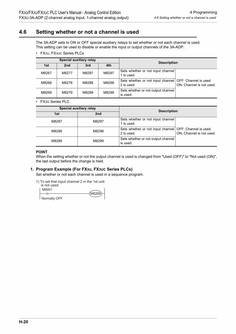
4 Programming4.6 Setting whether or not a channel is used
FX3G/FX3U/FX3UC PLC User's Manual - Analog Control EditionFX3U-3A-ADP (2-channel analog Input, 1-channel analog output)
4.6 Setting whether or not a channel is used
The 3A-ADP sets to ON or OFF special auxiliary relays to set whether or not each channel is used.This setting can be used to disable or enable the input or output channels of the 3A-ADP.• FX3U, FX3UC Series PLCs
• FX3G Series PLC
POINTWhen the setting whether or not the output channel is used is changed from "Used (OFF)" to "Not used (ON)",the last output before the change is held.
1. Program Example (For FX3U, FX3UC Series PLCs)Set whether or not each channel is used in a sequence program.
Special auxiliary relayDescription
1st 2nd 3rd 4th
M8267 M8277 M8287 M8297 Sets whether or not input channel1 is used.
OFF: Channel is used.ON: Channel is not used.M8268 M8278 M8288 M8298 Sets whether or not input channel
2 is used.
M8269 M8279 M8289 M8299 Sets whether or not output channelis used.
Special auxiliary relayDescription
1st 2nd
M8287 M8297 Sets whether or not input channel1 is used.
OFF: Channel is used.ON: Channel is not used.M8288 M8298 Sets whether or not input channel
2 is used.
M8289 M8299 Sets whether or not output channelis used.
1) To set that input channel 2 in the 1st unit is not used:
M8001M8268
Normally OFF
H-20
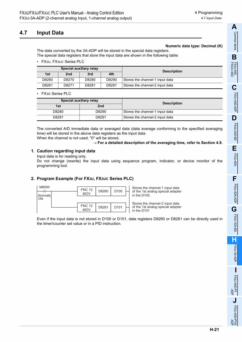
4 Programming4.7 Input Data
FX3G/FX3U/FX3UC PLC User's Manual - Analog Control EditionFX3U-3A-ADP (2-channel analog Input, 1-channel analog output)
A
Comm
on Items
B
FX3U-4ADFX3UC-4AD
C
FX3U-4AD-ADP
D
FX3G-2AD-BD
E
FX3U-4DA
F
FX3U-4DA-ADP
G
FX3G-1DA-BD
H
FX3U-3A-ADP
I
FX3U-4AD-PT -ADP
J
FX3U-4AD-PTW -ADP
4.7 Input Data
Numeric data type: Decimal (K)The data converted by the 3A-ADP will be stored in the special data registers.The special data registers that store the input data are shown in the following table:• FX3U, FX3UC Series PLC
• FX3G Series PLC
The converted A/D immediate data or averaged data (data average conforming to the specified averagingtime) will be stored in the above data registers as the input data.When the channel is not used, "0" will be stored.
→ For a detailed description of the averaging time, refer to Section 4.9.
1. Caution regarding input dataInput data is for reading only.Do not change (rewrite) the input data using sequence program, indicator, or device monitor of theprogramming tool.
2. Program Example (For FX3U, FX3UC Series PLC)
Even if the input data is not stored in D100 or D101, data registers D8260 or D8261 can be directly used inthe timer/counter set value or in a PID instruction.
Special auxiliary relayDescription
1st 2nd 3rd 4thD8260 D8270 D8280 D8290 Stores the channel-1 input dataD8261 D8271 D8281 D8291 Stores the channel-2 input data
Special auxiliary relayDescription
1st 2ndD8280 D8290 Stores the channel-1 input dataD8281 D8291 Stores the channel-2 input data
M8000
NormallyON
FNC 12MOV
D8260 D100
FNC 12MOV
D8261 D101
Stores the channel-1 input dataof the 1st analog special adapter
Stores the channel-2 input dataof the 1st analog special adapter
in the D100.
in the D101
H-21

4 Programming4.8 Output Setting Data
FX3G/FX3U/FX3UC PLC User's Manual - Analog Control EditionFX3U-3A-ADP (2-channel analog Input, 1-channel analog output)
4.8 Output Setting Data
Numeric data type: Decimal (K)The 3A-ADP performs D/A conversion on the output setting data (digital data) into analog data, and outputsthe analog data.Use the special data registers shown in the following table for the output setting data:• FX3U, FX3UC Series PLC
• FX3G Series PLC
1. Program Example (For FX3U, FX3UC Series PLC)
Using the indicator or the sequence program, input the digital data to be subject to D/A conversion (to beoutput as analog data) in D102.
Special auxiliary relayDescription
1st 2nd 3rd 4thD8262 D8272 D8282 D8292 Output setting data
Special data registerDescription
1st 2ndD8282 D8292 Output setting data
M8000
Normally ON
FNC 12MOV
D102 D8262Performs D/A conversion using the digital
data stored in the D102 of the 1st analog
special adapter.
H-22

4 Programming4.9 Averaging Time
FX3G/FX3U/FX3UC PLC User's Manual - Analog Control EditionFX3U-3A-ADP (2-channel analog Input, 1-channel analog output)
A
Comm
on Items
B
FX3U-4ADFX3UC-4AD
C
FX3U-4AD-ADP
D
FX3G-2AD-BD
E
FX3U-4DA
F
FX3U-4DA-ADP
G
FX3G-1DA-BD
H
FX3U-3A-ADP
I
FX3U-4AD-PT -ADP
J
FX3U-4AD-PTW -ADP
4.9 Averaging Time
Setting range: 1 to 4095Initial value: K1
Numeric data type: Decimal (K)If the averaging time is set for the 3A-ADP, the average data will be stored as the input data. The averagingtime can be set for each channel.Set the averaging time in the following special data registers:• FX3U, FX3UC Series PLC
• FX3G Series PLC
1. Cautions regarding averaging time setting• If the averaging time is set to "1", the immediate data is stored to the special data register.• If the averaging time is set in the range from 2 to 4095, the average value will be calculated to conform to
the set averaging time, and the average value obtained will be stored in the special data register.• After turning the PLC power on, the current data is stored to special data registers until the number of data
items reaches the set averaging time. After this, the average data will be stored.• Set the averaging time in the range from 1 to 4095. If the set value is outside the setting range, an error
signal will be output.• If the averaging time is set to "0" or smaller, the PLC will perform as if the averaging time is set to "1".
If the averaging time is set to "4096" or larger, the PLC will perform as if the averaging time is set to "4096".→ For a detailed description of the error status, refer to Section 6.5.
2. Program Example (For FX3U, FX3UC Series PLC)
Special auxiliary relayDescription
1st 2nd 3rd 4thD8264 D8274 D8284 D8294 Averaging time for channel-1 data
D8265 D8275 D8285 D8295 Averaging time for channel-2 data
Special data registerDescription
1st 2ndD8284 D8294 Averaging time for channel-1 data
D8285 D8295 Averaging time for channel-2 data
M8000
NormallyON
FNC 12MOV
K1 D8264
FNC 12MOV
K5 D8265
Sets the averaging time forchannel-1 of the 1st analogspecial adapter to 1.
Sets the averaging time forchannel-2 of the 1st analogspecial adapter to 5.
H-23

4 Programming4.10 Error Status
FX3G/FX3U/FX3UC PLC User's Manual - Analog Control EditionFX3U-3A-ADP (2-channel analog Input, 1-channel analog output)
4.10 Error Status
If an error is detected in the 3A-ADP, the error status data will be stored in the corresponding special dataregister.The following table shows the special data registers that store the error status data:• FX3U, FX3UC Series PLC
• FX3G Series PLC
Check the ON/OFF status of each bit of the error status data register to check the description of the error.Errors are assigned to the bits as shown in the following table. Create a program to detect errors.
→ For a detailed description of the error status, refer to Section 6.5.
*1. A 3A-ADP hardware error (b6) is valid only when the use of analog input is set.Detection of power supply error is valid only when the use of analog input channel 2 is set.
*2. A 3A-ADP communication data error (b7) is valid only when the use of analog input is set.*3. The FX3U/FX3UC Series PLC Ver.2.70 or later supports the under-scale detection function. The under-
scale detection function is valid only for current input mode.
1. Caution regarding use of error status dataIf a 3A-ADP hardware error (b6) or 3A-ADP communication data error (b7) is detected, it is necessary to clearthe error status with a program at the next power-on of the PLC.For this reason, be sure to create the following program:• FX3G, FX3U, FX3UC Series PLC
*1. "1st" for the FX3G PLC.
Special auxiliary relayDescription
1st 2nd 3rd 4thD8268 D8278 D8288 D8298 Stores the error status data.
Special data registerDescription
1st 2ndD8288 D8298 Stores the error status data.
Bit Description Bit Description
b0 Channel-1 over-scale detection b63A-ADP hardware error(Power supply error included)*1
b1 Channel-2 over-scale detection b7 3A-ADP communication data error*2
b2 Output data setting error b8 Channel-1 under-scale detection*3
b3 Unused b9 Channel-2 under-scale detection*3
b4 EEPROM error b10 to b15 Unused
b5 Averaging time setting error - -
M8002Error status of 3rd analog special adapterb6 = OFF (hardware error)
Error status of 3rd analog status registerb7 = OFF (communication data error)
RST M6
RST M7
Initial pulse
MOV D8288 K4M0
M8000
Normally ON
MOV D8288K4M0
*1
*1
H-24
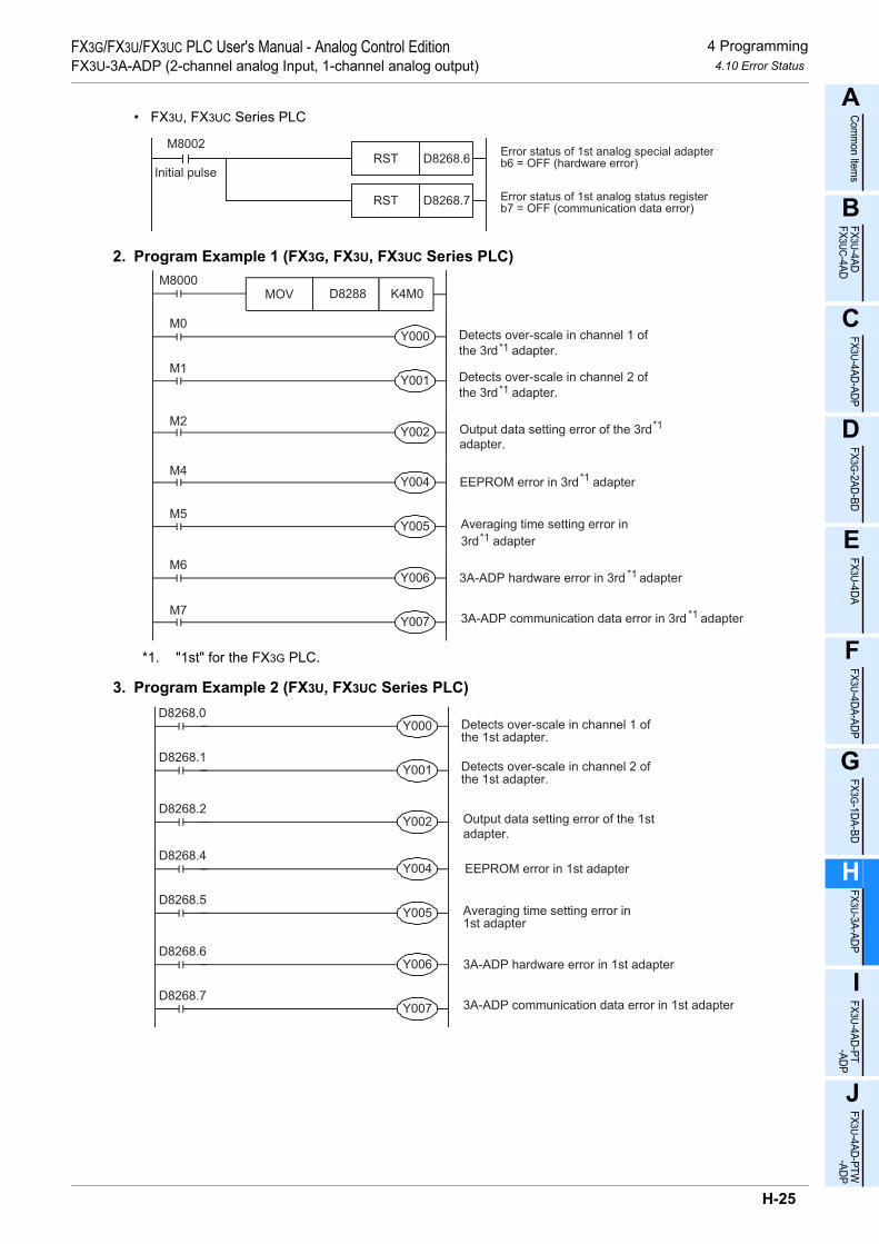
4 Programming4.10 Error Status
FX3G/FX3U/FX3UC PLC User's Manual - Analog Control EditionFX3U-3A-ADP (2-channel analog Input, 1-channel analog output)
A
Comm
on Items
B
FX3U-4ADFX3UC-4AD
C
FX3U-4AD-ADP
D
FX3G-2AD-BD
E
FX3U-4DA
F
FX3U-4DA-ADP
G
FX3G-1DA-BD
H
FX3U-3A-ADP
I
FX3U-4AD-PT -ADP
J
FX3U-4AD-PTW -ADP
• FX3U, FX3UC Series PLC
2. Program Example 1 (FX3G, FX3U, FX3UC Series PLC)
*1. "1st" for the FX3G PLC.
3. Program Example 2 (FX3U, FX3UC Series PLC)
M8002Error status of 1st analog special adapterb6 = OFF (hardware error)
Error status of 1st analog status registerb7 = OFF (communication data error)
RST D8268.6
RST D8268.7
Initial pulse
Y000M0
M8000
M1
M2
M4
M5
M6
M7
Y001
Y002
Y004
Y005
Y006
Y007
Detects over-scale in channel 1 of
the 3rd adapter.
Detects over-scale in channel 2 of
Output data setting error of the 3rd
adapter.
EEPROM error in 3rd adapter
Averaging time setting error in
3rd adapter
3A-ADP hardware error in 3rd adapter
3A-ADP communication data error in 3rd adapter
MOV D8288 K4M0
*1
*1
*1
*1
*1
the 3rd adapter.*1
*1
Y000D8268.0
Y001D8268.1
Y002D8268.2
Y004D8268.4
Y005D8268.5
Y006D8268.6
Y007D8268.7
Detects over-scale in channel 1 ofthe 1st adapter.
Detects over-scale in channel 2 ofthe 1st adapter.
Output data setting error of the 1st
adapter.
EEPROM error in 1st adapter
Averaging time setting error in1st adapter
3A-ADP hardware error in 1st adapter
3A-ADP communication data error in 1st adapter
H-25

4 Programming4.11 Model Code
FX3G/FX3U/FX3UC PLC User's Manual - Analog Control EditionFX3U-3A-ADP (2-channel analog Input, 1-channel analog output)
4.11 Model Code
Initial value: K50Numeric data type: Decimal (K)
When the 3A-ADP is connected, model code "50" is stored in the corresponding special data register.The following table shows the special data registers that store the model code:• FX3U, FX3UC Series PLC
• FX3G Series PLC
Use the special data registers above to check whether a 3A-ADP is connected or not.
1. Program Example (FX3U, FX3UC Series PLC)
Special auxiliary relayDescription
1st 2nd 3rd 4thD8269 D8279 D8289 D8299 Model code
Special data registerDescription
1st 2ndD8289 D8299 Model code
Checks the model code of the 1stanalog special adapter
FNC224LD =
D8289 K50 Y007
H-26

4 Programming4.12 Basic Program Example
FX3G/FX3U/FX3UC PLC User's Manual - Analog Control EditionFX3U-3A-ADP (2-channel analog Input, 1-channel analog output)
A
Comm
on Items
B
FX3U-4ADFX3UC-4AD
C
FX3U-4AD-ADP
D
FX3G-2AD-BD
E
FX3U-4DA
F
FX3U-4DA-ADP
G
FX3G-1DA-BD
H
FX3U-3A-ADP
I
FX3U-4AD-PT -ADP
J
FX3U-4AD-PTW -ADP
4.12 Basic Program Example
Create the following basic program example to input/output analog conversion data.• FX3G, FX3U, FX3UC Series PLCThe following program will set channel 1 of the 3rd*1 adapter to voltage input mode and channel 2 to currentinput mode, and will store the converted A/D value of channel-1 data into D100 and that of channel-2 datainto D101. The program also sets "voltage output" for output channels, and sets the D/A conversion output toD102.
Even if the input data is not stored into D100 or D101, the data registers D8280 or D8281 can be directly usedin the timer/counter setting value or in a PID instruction.Using the indicator or the sequence program, input the digital data to be subject to D/A conversion (to beoutput as analog data) in D102.
*1. "1st" for the FX3G PLC.
M8002RST M6
RST M7
M8000FNC 12
MOVK5 D8284
FNC 12MOV
K5 D8285
M8000
M8000
FNC 12MOV
D8280 D100
FNC 12MOV
D8281 D101
M8000 FNC 12MOV
D8288 K4M0
FNC 12MOV
K4M0 D8288
M8001M8280
M8000M8281
FNC 12MOV
D102 D8282
M8001M8282
M8286
Set the input mode of channel 1 to the voltage
input mode (0 V to 10 V).
Set the input mode of channel 2 to the current
input mode (4 mA to 20 mA).
Set the output mode to the voltage output mode
(0 V to 10 V).
Set the output holding function.
Error status: b6 = OFF
Normally OFF
Normally ON
Normally
OFF
Initial
pulseError status: b7 = OFF
Set the averaging time to "5" for channel-1 data.
Set the averaging time to "5" for channel-2 data.
Stores the A/D converted channel-1 digital data
into D100.
Stores the A/D converted channel-2 digital data
into D101.
Performs D/A conversion with the digital data
stored in D102.
H-27

4 Programming4.12 Basic Program Example
FX3G/FX3U/FX3UC PLC User's Manual - Analog Control EditionFX3U-3A-ADP (2-channel analog Input, 1-channel analog output)
• FX3U, FX3UC Series PLCThe following program will set channel 1 of the 1st adapter to voltage input mode and channel 2 to currentinput mode, and will store the converted A/D value of channel-1 data into D100 and that of channel-2 datainto D101. The program will also set "voltage output" for output channels, and set the digital D/A conversionoutput to D102.
Even if the input data is not stored into D100 or D101, the data registers D8260 or D8261 can be directly usedin the timer/counter setting value or in a PID instruction.Using the indicator or the sequence program, input the digital data to be subject to D/A conversion (to beoutput as analog data) in D102.
M8002RST
RST
M8000FNC 12
MOVK5 D8264
FNC 12MOV
K5 D8265
M8000
M8000
FNC 12MOV
D8260 D100
FNC 12MOV
D8261 D101
M8001M8260
M8000M8261
FNC 12MOV
D102 D8262
M8001M8262
M8266
D8268.6
D8268.7
Set the input mode of channel 1 to the voltage
input mode (0 V to 10 V).Normally OFF
Normally ON
Normally
OFF
Initial
pulse
Set the input mode of channel 2 to the current
input mode (4 mA to 20 mA).
Set the output mode to the voltage output mode
(0 V to 10 V).
Set the output holding function.
Error status: b6 = OFF
Error status: b7 = OFF
Set the averaging time to "5" for channel-1 data.
Set the averaging time to "5" for channel-2 data.
Stores the A/D converted channel-1 digital data
into D100.
Stores the A/D converted channel-2 digital data
into D101.
Performs D/A conversion with the digital data
stored in D102.
H-28

5 Changing of Input/output Characteristics5.1 Example: Changing of Voltage Input Characteristics
FX3G/FX3U/FX3UC PLC User's Manual - Analog Control EditionFX3U-3A-ADP (2-channel analog Input, 1-channel analog output)
A
Comm
on Items
B
FX3U-4ADFX3UC-4AD
C
FX3U-4AD-ADP
D
FX3G-2AD-BD
E
FX3U-4DA
F
FX3U-4DA-ADP
G
FX3G-1DA-BD
H
FX3U-3A-ADP
I
FX3U-4AD-PT -ADP
J
FX3U-4AD-PTW -ADP
5. Changing of Input/output Characteristics
Use the scaling instruction (SCL/FNC 259) for the FX3U/FX3UC Series PLC to change the input/output characteristics. FX3G Series PLCs do not support the scaling instruction. Use sequence programs to change the input/output characteristics.→ For a detailed description of scaling instruction, refer to the FX3G/FX3U/FX3UC Series Programming
Manual - Basic & Applied Instruction Edition.
5.1 Example: Changing of Voltage Input Characteristics
This section describes an example of a program that can change the digital output range of 400 to 2000(when the voltage input is 1 to 5V) to the digital output range of 0 to 10000.
1. Input characteristics
0
4000
10VAnalog input
400
2000
5V1V 0
10000
Digital value actually obtainedby A/D conversion
2000(5V)400(1V)
Dig
ital outp
ut
tobe c
alc
ula
ted
(D110)
Voltage input characteristics(product specifications)
Digital output value to be changed
X-axis
Y-axis
Dig
ita
l o
utp
ut
H-29

5 Changing of Input/output Characteristics5.1 Example: Changing of Voltage Input Characteristics
FX3G/FX3U/FX3UC PLC User's Manual - Analog Control EditionFX3U-3A-ADP (2-channel analog Input, 1-channel analog output)
2. Example of program 1 (FX3U, FX3UC Series PLC)• For example, create the following program to change the digital input data of the 1st analog special
adapter:M8001
M8260 Sets the input mode of channel 1 to the voltage input mode(0 V to 10 V)
M8002RST D8268.6
RST D8268.7
Error status: b6 = OFF
Error status: b7 = OFF
M8000FNC 12
MOVK1 D8264 Sets the averaging time to "1" for the channel-1 data
M8002FNC 12
MOVK2 D50
FNC 12MOV
K400 D51
FNC 12MOV
K0 D52
FNC 12MOV
K2000 D53
FNC 12MOV
K10000 D54
M8000
Program for setting scaling instruction data table
The scaling instruction operation results will be stored in D100.
Item
Number of points
Startpoint
X-coordinate
Y-coordinate
Endpoint
X-coordinate
Y-coordinate
Description
Sets the number of points
A/D converted digital valuestart point data
Digital output value of changedX-axis value start point
2
Value Device
D50
400 D51
0 D52
A/D converted digital value endpoint data
Digital output value of changedX-axis value end point
2000 D53
10000 D54
FNC 259SCL
D8260 D50 D100
H-30

5 Changing of Input/output Characteristics5.1 Example: Changing of Voltage Input Characteristics
FX3G/FX3U/FX3UC PLC User's Manual - Analog Control EditionFX3U-3A-ADP (2-channel analog Input, 1-channel analog output)
A
Comm
on Items
B
FX3U-4ADFX3UC-4AD
C
FX3U-4AD-ADP
D
FX3G-2AD-BD
E
FX3U-4DA
F
FX3U-4DA-ADP
G
FX3G-1DA-BD
H
FX3U-3A-ADP
I
FX3U-4AD-PT -ADP
J
FX3U-4AD-PTW -ADP
3. Example of program 2 (FX3G Series PLC)• For example, create the following program to change the digital input data (D110) of the 1st analog special
adapter:
4. Cautions regarding programming• GX Developer version 8.13P or later supports scaling instruction (SCL/FNC 259).• If the A/D converted digital value is out of the data table range specified by the scaling instruction (SCL/
FNC 259), the FX Series PLC will detect an operation error (error code: K6706).
D110 K400 D111FNC 21
SUB
M8002RST M6
RST M7
Error status: b6 = OFF
Error status: b7 = OFF
M8000K1 D8284
Sets the averaging scaling to "1"
for the channel-1 data.
Check to make sure the digital
value (D110) is in range.
Calculation for changing input
characteristics.
Stores the operation result in D100.
M8000D8280 D110
M8000 FNC 12MOV
D8288 K4M0
M8001M8280 Sets the input mode of channel 1 to the
voltage input mode
(0V to 10V).
D111 K10000 D112FNC 22
MUL
D112 K1600 D100FNC 23
DDIV
K4M0 D8288
M10
M10FNC 230LD>=
D110 K400 FNC 237AND<=
D110 K2000
FNC 12MOV
FNC 12MOV
FNC 12MOV
H-31

5 Changing of Input/output Characteristics5.2 Example: Changing of Voltage Output Characteristics
FX3G/FX3U/FX3UC PLC User's Manual - Analog Control EditionFX3U-3A-ADP (2-channel analog Input, 1-channel analog output)
5.2 Example: Changing of Voltage Output Characteristics
This section describes an example of a program that can change the digital value range from 400 to 2000(when analog output range is 1 to 5V) to 0 to 10000.A specified digital value is inputted into D120.
1. Output characteristics
2. Example of program 1 (FX3U, FX3UC Series PLC)• For example, create the following program to change the digital output of the 1st analog special adapter.
0 10000S
pe
cifie
d d
igita
l o
utp
ut
va
lue
to
be
actu
ally
su
bje
ct to
D/A
co
nve
rsio
n
2000(5V)
400(1V)
Desired digital value (D120)
Voltage output characteristics(product specifications)
Digital value characteristicsto be changed
X-axis0 4000
10V
An
alo
g o
utp
ut
Digital value input400 2000
5V
1V
Y-axis
M8001M8262 Sets the output mode of channel 1 to the voltage output
mode.
M8002FNC 12
MOVK2 D50
FNC 12MOV
K0 D51
FNC 12MOV
K400 D52
FNC 12MOV
K10000 D53
FNC 12MOV
K2000 D54
M8000
Program for setting scaling instruction data table
The result of operation by scaling instruction will be storedin the D8262.
M8266 Sets the output holding function for channel 1.
Item
Number of points
Startpoint
X-coordinate
Y-coordinate
Endpoint
X-coordinate
Y-coordinate
Description
Sets the number of points.
Digital value of specifiedstart point on X-axis
Digital value of desired D/Aconversion start point
2
Value Device
D50
0 D51
400 D52
Digital value of specified endpoint on X-axis
Digital value of desired D/Aconversion end point
10000 D53
2000 D54
FNC 259SCL
D120 D50 D8262
Normally
OFF
H-32

5 Changing of Input/output Characteristics5.2 Example: Changing of Voltage Output Characteristics
FX3G/FX3U/FX3UC PLC User's Manual - Analog Control EditionFX3U-3A-ADP (2-channel analog Input, 1-channel analog output)
A
Comm
on Items
B
FX3U-4ADFX3UC-4AD
C
FX3U-4AD-ADP
D
FX3G-2AD-BD
E
FX3U-4DA
F
FX3U-4DA-ADP
G
FX3G-1DA-BD
H
FX3U-3A-ADP
I
FX3U-4AD-PT -ADP
J
FX3U-4AD-PTW -ADP
3. Example of program 2 (FX3G Series PLC)• For example, create the following program to change the digital output data (D120) of the 1st analog
special adapter.
4. Cautions regarding programming• GX Developer version 8.13P or later supports scaling instruction (SCL/FNC259).• If the input digital value for the D/A conversion is out of the data table range specified by scaling instruction
(SCL/FNC259), the FX Series PLC will detect an operation error (error code: K6706).
Sets the output mode to the voltage
output mode.
D123 K400 D127 FNC 20
ADD
D121 K10000 D123 FNC 23
DDIV
D120 K1600 D121 FNC 22
MUL
M20
M8001
Normally
OFF
M8282
FNC 12MOV
D127 D8282
M8286 Sets the output holding function.
M20FNC 230LD>=
D120 K0 FNC 237AND<=
D120 K10000Check to make sure the digital
value (D120) is in range.
Calculation for changing output
characteristics.
Stores the operation result in D8282.
H-33

6 Troubleshooting6.1 PLC Version Number Check
FX3G/FX3U/FX3UC PLC User's Manual - Analog Control EditionFX3U-3A-ADP (2-channel analog Input, 1-channel analog output)
6. Troubleshooting
This chapter describes troubleshooting methods and error statuses.Refer to the following items when conversion data is not input or output, or when proper digital values are notinput or output.• PLC version number• Installation• Wiring• Special devices• Programs• Error status
6.1 PLC Version Number Check
• Check the version number of the FX3U, FX3UC Series PLC. The version number should be 2.61 or later.• Check the version number of the FX3G Series PLC. The version number should be 1.20 or later.
→ For a detailed description of the version number check method, refer to Section 1.3.
6.2 Wiring Check
Check the following items for wiring:
1. PowerThe 3A-ADP needs driving power. Verify that the power supply line is properly connected. Also check that thePOWER indicator lamp of the 3A-ADP is on.
2. Analog input/output lineUse 2-core twisted shielded pair cable for the analog input/output line. In addition, be sure to separate theanalog input line from other power lines or inductive lines.
3. Use of current input modeTo use the current input mode for a channel, be sure to shortcircuit the line between the V + terminal and theI +terminal ( : channel number) of the channel. If the line is not shortcircuited, data will not be convertedinto proper digital data.
→ For a detailed description of wiring, refer to Chapter 3.
6.3 Special Device Check
Check whether the special devices for the 3A-ADP are being used correctly:
1. Input mode switchingCheck that the special device for switching the input mode is set correctly.Turn off the device to set the input mode to the voltage input mode. Turn on the device to set the input modeto the current input mode.
2. Output mode switchingVerify that the special device for switching the output mode is correctly set.Turn off the device to set the output mode to the voltage output mode. Turn on the device to set the outputmode to the current output mode.
3. Input dataVerify that the special device of the selected channel is correctly selected. This special device should beselected depending on the connecting position and the channel.
H-34

6 Troubleshooting6.4 Program Check
FX3G/FX3U/FX3UC PLC User's Manual - Analog Control EditionFX3U-3A-ADP (2-channel analog Input, 1-channel analog output)
A
Comm
on Items
B
FX3U-4ADFX3UC-4AD
C
FX3U-4AD-ADP
D
FX3G-2AD-BD
E
FX3U-4DA
F
FX3U-4DA-ADP
G
FX3G-1DA-BD
H
FX3U-3A-ADP
I
FX3U-4AD-PT -ADP
J
FX3U-4AD-PTW -ADP
4. Output setting dataCheck that the special device of the selected channel is correctly selected. This special device should beselected depending on the connected position and the channel.
5. Averaging timeCheck that the set averaging time is within the specified range. The averaging time should be set in the rangefrom 1 to 4095. If the set averaging time is outside the specified range, an error occurs.
6. Setting whether or not each channel is usedCheck whether each channel is set correctly.Set a channel to OFF when using it. Set a channel to ON when not using it.
7. Error statusCheck that no error is detected in the 3A-ADP.If an error is detected, check the details of the error, and then check the wiring and programs.
→ For a detailed description of special devices, refer to Chapter 4.
6.4 Program Check
Check the following items for the program:
1. Clearing of error status at power onWhen the power is turned off and then on again, the error status should be cleared (b6 and b7 should turn off)using the program.
2. Check of storage devicesVerify that different values are not being stored in the same device by other parts of the program.
3. Device for setting specified digital valueCheck that different values are not written to this device using other programs.
6.5 Error Status Check
If an error occurs in the 3A-ADP, the corresponding bit will turn ON.The bit which is turned ON due to the error status is held ON until overwritten to OFF by the program or thepower is cycled. If b6 or b7 is turned ON, then it is necessary to clear the error status using the program thenext time the power of the PLC is cycled.
*1. 3A-ADP hardware error (b6) is valid only when use of analog input is set.Detection of power supply error is valid only when use of the analog input channel 2 is set.
*2. 3A-ADP communication data error (b7) is valid only when use of analog input is set.*3. The FX3U/FX3UC Series PLC Ver.2.70 or later supports the under-scale detection function. The under-
scale detection function is valid only for current input mode.
Bit Description Bit Description
b0 Channel-1 over-scale detection b63A-ADP hardware error(Power supply error included)*1
b1 Channel-2 over-scale detection b7 3A-ADP communication data error*2
b2 Output data setting error b8 Channel-1 under-scale detection*3
b3 Unused b9 Channel-2 under-scale detection*3
b4 EEPROM error b10 to b15 Unused
b5 Averaging time setting error - -
H-35

6 Troubleshooting6.5 Error Status Check
FX3G/FX3U/FX3UC PLC User's Manual - Analog Control EditionFX3U-3A-ADP (2-channel analog Input, 1-channel analog output)
To solve the problem, refer to the troubleshooting method described below:
1. Over-scale detection (b0, b1)1) Description of error
The input analog value (voltage or current value) is outside the specified range.Voltage input mode : The input voltage value is over the specified upper limit of 10.2 V.Current input mode : The input current value is over the specified upper limit of 20.4 mA.
2) RemedyCheck that the input analog value is within the specified range. Also check the wiring.
2. Output data setting error (b2)1) Description of error
The specified digital value is outside the specified range.Analog data will not be correctly output.
2) RemedyCheck that the specified digital value is within the specified range.
3. EEPROM error (b4)1) Description of error
The adjustment data which was set in the EEPROM before delivery from our factory cannot be read outproperly or has been destroyed.
2) RemedyPlease contact the nearest Mitsubishi Electric distributor office.
4. Averaging time setting error (b5)1) Description of error
The averaging time set for one of the channels (channels 1 to 2) is outside the specified range: 1 to 4095.2) Remedy
Check that the averaging time is set correctly for each channel.
5. 3A-ADP hardware error (b6)1) Description of error
The 3A-ADP is not operating properly.2) Remedy
Check that the 3A-ADP is correctly connected to the PLC.If the problem cannot be solved even after the above check, please contact the nearest MitsubishiElectric distributor office.
6. 3A-ADP communication data error (b7)1) Description of error
A communication error is detected between the 3A-ADP and the PLC.2) Remedy
Check that the 3A-ADP is correctly connected to the PLC.If the problem cannot be solved even after the above check, please contact the nearest MitsubishiElectric distributor office.
7. Under-scale detection (b8, b9)1) Description of error
The input analog value (current value) is below the specified lower limit.This error is only detected for the current input mode, and indicates the input current is less than 2 mA.
2) RemedyCheck that the input analog value is within the specified range. Also check the wiring.
H-36

A
Comm
on Items
B
FX3U-4ADFX3UC-4AD
C
FX3U-4AD-ADP
D
FX3G-2AD-BD
E
FX3U-4DA
F
FX3U-4DA-ADP
G
FX3G-1DA-BD
H
FX3U-3A-ADP
I
FX3U-4AD-PT -ADP
J
FX3U-4AD-PTW -ADP
FX3G/FX3U/FX3UC PLC User's Manual - Analog Control EditionFX3U-4AD-PT-ADP (4-channel Platinum Resistance Thermometer Data Input)
FX3G/FX3U/FX3UC Series Programmable Controllers
User's Manual [Analog Control Edition] FX3U-4AD-PT-ADP (4-channel Platinum Resistance Thermometer Data Input)
Foreword
This manual describes the specifications, wiring, and operation methods for the FX3U-4AD-PT-ADP special adapter (4-channel platinum resistance thermometer input) and should be read and understood before attempting to install or use the unit.Store this manual in a safe place so that you can take it out and read it whenever necessary. Always forward it to the end user.
© 2005 MITSUBISHI ELECTRIC CORPORATION
This manual confers no industrial property rights or any rights of any other kind, nor does it confer any patentlicenses. Mitsubishi Electric Corporation cannot be held responsible for any problems involving industrial propertyrights which may occur as a result of using the contents noted in this manual.
I-1

FX3G/FX3U/FX3UC PLC User's Manual - Analog Control EditionFX3U-4AD-PT-ADP (4-channel Platinum Resistance Thermometer Data Input)
I-2

1 Outline1.1 Outline of Functions
FX3G/FX3U/FX3UC PLC User's Manual - Analog Control EditionFX3U-4AD-PT-ADP (4-channel Platinum Resistance Thermometer Data Input)
A
Comm
on Items
B
FX3U-4ADFX3UC-4AD
C
FX3U-4AD-ADP
D
FX3G-2AD-BD
E
FX3U-4DA
F
FX3U-4DA-ADP
G
FX3G-1DA-BD
H
FX3U-3A-ADP
I
FX3U-4AD-PT -ADP
J
FX3U-4AD-PTW -ADP
1. Outline
This chapter describes the outline of FX3U-4AD-PT-ADP (referred to as PT-ADP).
1.1 Outline of Functions
The FX3U-4AD-PT-ADP is an analog special adapter. Connect the FX3U-4AD-PT-ADP to the FX3U/FX3UC/FX3G Series PLC to read the temperature data from the 4-channel platinum resistance thermometers.1) Up to 4 PT-ADP units can be connected to the FX3U/FX3UC Series PLC.
Up to 2*1 PT-ADP units can be connected to the FX3G Series PLC. (including other analog special adapters)
2) After connection of the platinum resistance thermometer (Pt100), measurement of temperature will bepossible.
3) The temperature measurement data will be automatically written to the special data registers of the FX3U/FX3UC/FX3G Series PLC.
Number of connectable
units
……For a detaileddescription of wiring,refer to Chapter 3.
……To check the connectablePLC model number, referto Section 1.3.
Point and section to bereferred to
System
……
Special devices ……For a detailed descriptionof special devices, refer toChapter 4.
For a detailed descriptionof a basic program, refer toSection 4.8.
Analog data
Refer to the system configuration shown in the User's Manual - Hardware Edition to check the number of connectable unitsand to configure the entire system.
*2. The expansion board is not required when connecting with the FX
For the FX3G Series PLC a connector conversion adapter is used.
3UC (D, DSS) PLC.
FX3U, FX3UC Series PLC : 4 maximum
FX3G Series PLC : 2*1 maximum(including other analog special adapters)
1st adapter M/D8260 to M/D8269
M/D8270 to M/D8279
M/D8280 to M/D8289
M/D8290 to M/D8299
2nd adapter
3rd adapter
4th adapter
++
Expansionboard*2
FX3U/FX3UC/FX3G Series PLC
For FX3U, FX3UC
Series PLC
4thadapter
3rdadapter
2ndadapter
1stadapter
Transfer direction
*1. Only 1 analog special adapter can be connected to the 14-point and 24-point type main unit.
Platinum resistance thermometersensor(Pt100)
Description
Measurementtemperature
Setting of temperatureunit
Setting of averaging time
I-3

1 Outline1.2 Setup Procedure Before Starting Operation
FX3G/FX3U/FX3UC PLC User's Manual - Analog Control EditionFX3U-4AD-PT-ADP (4-channel Platinum Resistance Thermometer Data Input)
1.2 Setup Procedure Before Starting Operation
Before starting analog input using the PT-ADP, follow the procedure below to set up the system:
Specifications:•Operation environment•Performance specifications•Input characteristics
Specifications check
Refer to Chapter 2.
System configuration and selection
Wiring
Refer to Chapter 3.
FX3U-4AD-PT-ADP
System configuration: (Refer to the common pages for analog control.)•Selection of units
Refer to the commonpages.
Wiring:•Power supply line•Platinum resistance thermometer sensor line
Outline of system:•Compatible PLC version number•Compatible programming tool version number
Outline
Refer to Chapter 1.
Programming
Refer to Chapter 4.
Programming:•Details of special devices•Examples of basic programs
If the error status data or the input digital value isabnormal, refer to Chapter 5 "Troubleshooting."
I-4

1 Outline1.3 Connectable PLC and Its Version Number
FX3G/FX3U/FX3UC PLC User's Manual - Analog Control EditionFX3U-4AD-PT-ADP (4-channel Platinum Resistance Thermometer Data Input)
A
Comm
on Items
B
FX3U-4ADFX3UC-4AD
C
FX3U-4AD-ADP
D
FX3G-2AD-BD
E
FX3U-4DA
F
FX3U-4DA-ADP
G
FX3G-1DA-BD
H
FX3U-3A-ADP
I
FX3U-4AD-PT -ADP
J
FX3U-4AD-PTW -ADP
1.3 Connectable PLC and Its Version Number
PT-ADP is compatible with the following PLC.
1. Version checkSpecial data register D8001 contains information for determining the PLC version.
→ For a detailed description of the version check, refer to A. Common Items Subsection 5.1.2.
2. How to check the manufacturer's serial numberThe year and month of production of the product can be checked on the nameplate, and on the front of theproduct.
→ For a detailed description of how to check the manufacturer's serial number,refer to A. Common Items Subsection 5.1.1.
1.4 Compatible Programming Tool Version Number
Use the programming tool with the following version number to create programs for PT-ADP of the FX3U/FX3UC/FX3G Series PLC:
1. GX Works2
2. GX Developer• FX3U/FX3UC Series PLC
• FX3G Series PLC
If a programming tool with the wrong version number is used, programming will not be possible.*1. For Ver. 8.13P to 8.24A of GX Developer, select FX3UC for the PLC type.
3. FX-30P
Compatible PLC Version number Date of productionFX3U Series PLC Ver. 2.20 or later After May 2005 (initial production)
FX3UC Series PLC Ver. 1.30 or later After August 2004
FX3G Series PLC Ver. 1.00 or later After June 2008 (initial production)
Software Version number RemarksGX Works2SW DNC-GXW2-J Ver. 1.07H or later -
GX Works2SW DNC-GXW2-E Ver. 1.08J or later -
Software Version number RemarksGX DeveloperSW D5C-GPPW-J Ver. 8.13P or later
When selecting the model, select FX3U(C)*1.GX DeveloperSW D5C-GPPW-E Ver. 8.18U or later
Software Version number RemarksGX Developer• SW D5C-GPPW-J• SW D5C-GPPW-E
Ver. 8.72A or later -
Model name Version number RemarksFX-30P Ver. 1.00 or later -
I-5

2 Specifications2.1 Generic Specifications
FX3G/FX3U/FX3UC PLC User's Manual - Analog Control EditionFX3U-4AD-PT-ADP (4-channel Platinum Resistance Thermometer Data Input)
2. Specifications
This chapter describes the general, power supply, and performance specifications for the PT-ADP.
2.1 Generic Specifications
*1. The criterion is shown in IEC61131-2.*2. If PT-ADP is connected to the FX3UC Series PLC, direct installation is not possible.*3.
→ For a detailed description of the grounding, refer to Section 3.6.*4. If the pressure is higher than the atmospheric pressure, do not use the PT-ADP.
The PT-ADP may malfunction.
Item SpecificationsAmbient temperature
0 to 55°C (32 to 131°F) when operating -25 to 75°C (-13 to 167°F) when stored
Relative humidity 5 to 95%RH (no condensation) when operating
Vibrationresistance*1
Frequency(Hz)
Acceleration(m/s2)
Half amplitude(mm)
Tested 10 times in each direction (X-, Y-, and Z-axis directions) (Total: 80 min, each)
DIN Rail Mounting10 - 57 - 0.035
57 - 150 4.9 -
Direct Mounting*210 to 57 − 0.075
57 to 150 9.8 −
Shock resistance*1 147 m/s2 Acceleration, Action time: 11ms, 3 times by half-sine pulse in each direction X, Y, and Z
Noise resistance
Using noise simulator of:Noise voltage: 1,000Vp-p / Noise width: 1µs / Rise: 1ns / Cycle: 30 to 100Hz
Dielectric withstand voltage
500 V AC, for 1 minBetween all terminals and ground terminal
Insulation resistance
5MΩ or more using 500V DC insulation resistance meter
GroundingClass D grounding (grounding resistance: 100 Ω or less) <Common grounding with a heavy electrical system is not allowed.>*3
Workingenvironment Free from corrosive or flammable gas and excessive conductive dusts
Workingaltitude < 2000m*4
PLC OtherequipmentPLC Other
equipmentPLC Otherequipment
Shared groundingGood condition
Common groundingNot allowed
Independent groundingBest condition
I-6

2 Specifications2.2 Power Supply Specifications
FX3G/FX3U/FX3UC PLC User's Manual - Analog Control EditionFX3U-4AD-PT-ADP (4-channel Platinum Resistance Thermometer Data Input)
A
Comm
on Items
B
FX3U-4ADFX3UC-4AD
C
FX3U-4AD-ADP
D
FX3G-2AD-BD
E
FX3U-4DA
F
FX3U-4DA-ADP
G
FX3G-1DA-BD
H
FX3U-3A-ADP
I
FX3U-4AD-PT -ADP
J
FX3U-4AD-PTW -ADP
2.2 Power Supply Specifications
2.3 Performance Specifications
Items SpecificationA/D conversion circuit driving power
24V DC +20% -15%, 50mA(It is necessary to connect a 24V DC power supply to the terminal block.)
Interface driving power5V DC, 15mA(Since the internal power is supplied from the FX Series main unit, it is notnecessary to supply the power.)
ItemsSpecifications
Centigrade (°C) Fahrenheit (°F)
Input signal 3-wire platinum resistance thermometer sensorPt100 JIS C 1604-1997
Rated temperature range -50°C to +250°C -58°F to +482°F
Digital output -500 to +2500 -580 to +4820
Resolution 0.1°C 0.18°F
Total accuracy• ±0.5% for full scale (when ambient temperature is 25°C±5°C)• ±1.0% for full scale (when ambient temperature is in the range from 0 to 55°C)
A/D conversion time
• FX3U/FX3UC Series PLC : 200µs (The data will be updated at every scan time.)• FX3G Series PLC : 250µs (The data will be updated at every scan time.)
→For a detailed description of data update, refer to Section 2.4.
Input characteristics
Insulation method
• The photocoupler is used to insulate the analog input area from the PLC.• The DC/DC converter is used to insulate the power supply line from the analog input
area.• Channels are not insulated from each other.
Number of I/O points occupied
0 points(This number is not related to the maximum number of input/output points of the PLC.)
0+250°C
+2500
-50°C
-500-55°
C
+255
°C
+2550
-550
0+482°F
+4820
-58°F
-580-67°
F
+491
°F
-670
+4910
I-7

2 Specifications2.4 A/D Conversion Time
FX3G/FX3U/FX3UC PLC User's Manual - Analog Control EditionFX3U-4AD-PT-ADP (4-channel Platinum Resistance Thermometer Data Input)
2.4 A/D Conversion Time
This section describes the A/D conversion time.
2.4.1 When connected to a FX3U, FX3UC PLC
1. A/D conversion and special data register update timingA/D conversion is performed at every scan time of the PLC.During execution of END instruction, the PLC performs A/D conversion, reads out the A/D converted data,and then writes the data in the special data registers.
2. A/D conversion during PLC stopEven if the PLC is stopped, A/D conversion will be performed and the special data registers will be updated.
3. If two or more analog special adapters are connectedDuring execution of the END instruction, data will be read out from all the connected adapters (in the order of 1st adapter → 2nd adapter … 4th adapter).
4. A/D conversion speed (data update time)During execution of the END instruction, the A/D converted data of all 4 channels will be read out in 200µs, and the data read out will be written to the special data registers.END instruction execution time will be "200µs × number of connected adapters."
FX3U/FX3UC Series PLCFX3U-4AD-PT-ADP
1stFX3U-4AD-PT-ADP
n'th
A/Dconversion
200µs/4ch
A/Dconversion
200µs/4ch
Digital value reading
A/D conversion startcommand
END instruction
Sequenceprogram
Digital value reading
A/D conversion startcommand
I-8

2 Specifications2.5 Temperature Measurement
FX3G/FX3U/FX3UC PLC User's Manual - Analog Control EditionFX3U-4AD-PT-ADP (4-channel Platinum Resistance Thermometer Data Input)
A
Comm
on Items
B
FX3U-4ADFX3UC-4AD
C
FX3U-4AD-ADP
D
FX3G-2AD-BD
E
FX3U-4DA
F
FX3U-4DA-ADP
G
FX3G-1DA-BD
H
FX3U-3A-ADP
I
FX3U-4AD-PT -ADP
J
FX3U-4AD-PTW -ADP
2.4.2 When connected to a FX3G PLC
1. A/D conversion and special data register update timingA/D conversion is performed at every scan time of the PLC.During execution of END instruction, the PLC performs A/D conversion, reads out the A/D converted data,and then writes the data in the special data registers.
2. A/D conversion during PLC stopEven if the PLC is stopped, A/D conversion will be performed and the special data registers will be updated.
3. If two analog special adapters are connectedDuring execution of the END instruction, data will be read out from all the connected adapters (in the order of 1st adapter → 2nd adapter).
4. A/D conversion speed (data update time)During execution of the END instruction, the A/D converted data of all 4 channels will be read out in 250µs, and the data read out will be written to the special data registers.END instruction execution time will be "250µs × number of connected adapters."
2.5 Temperature Measurement
To stabilize the temperature measurement, warm-up the system for 30 minutes or more after power-on.
FX3G Series PLCFX3U-4AD-PT-ADP
1stFX3U-4AD-PT-ADP
2nd
A/Dconversion
250µs/4ch
A/Dconversion
250µs/4ch
Digital value reading
A/D conversion startcommand
END instruction
Sequenceprogram
Digital value reading
A/D conversion startcommand
I-9

3 WiringFX3G/FX3U/FX3UC PLC User's Manual - Analog Control EditionFX3U-4AD-PT-ADP (4-channel Platinum Resistance Thermometer Data Input)
3. Wiring
This chapter describes the PT-ADP wiring.Observe the following caution to wire the PT-ADP.
WIRING PRECAUTIONS
• Make sure to cut off all phases of the power supply externally before attempting wiring work.Failure to do so may cause electric shock or damages to the product.
WIRING PRECAUTIONS
• Connect the DC power supply wiring to the dedicated terminals described in this manual.If an AC power supply is connected to a DC input/output terminal or DC power supply terminal, the PLC will beburnt out.
• Do not wire vacant terminals externally.Doing so may damage the product.
• Perform class D grounding (grounding resistance: 100Ω or less) to the grounding terminal on the main unit.Do not use common grounding with heavy electrical systems.
• When drilling screw holes or wiring, make sure cutting or wire debris does not enter the ventilation slits.Failure to do so may cause fire, equipment failures or malfunctions.
• Make sure to observe the following precautions in order to prevent malfunctions under the influence of noise:- Do not bundle the power line or twisted shielded cable together with or lay it close to the main circuit, high-
voltage line, or load line.Otherwise, noise disturbance and/or surge induction are likely to take place. As a guideline, lay the control line at least 100mm (3.94") or more away from the main circuit, high-voltage line, or load line.
- Ground the shield of the analog input/output cable at one point on the signal receiving side. However, do not use common grounding with heavy electrical systems.
• Make sure to properly wire to the European terminal board in accordance with the following precautions.Failure to do so may cause electric shock, equipment failures, a short-circuit, wire breakage, malfunctions, ordamage to the product.- The disposal size of the cable end should follow the dimensions described in the manual.- Tightening torque should follow the specifications in the manual.- Twist the end of strand wire and make sure there are no loose wires. - Do not solder-plate the electric wire ends.- Do not connect more than the specified number of wires or electric wires of unspecified size.- Affix the electric wires so that neither the terminal block nor the connected parts are directly stressed.
I-10

3 Wiring3.1 Terminal Layout
FX3G/FX3U/FX3UC PLC User's Manual - Analog Control EditionFX3U-4AD-PT-ADP (4-channel Platinum Resistance Thermometer Data Input)
A
Comm
on Items
B
FX3U-4ADFX3UC-4AD
C
FX3U-4AD-ADP
D
FX3G-2AD-BD
E
FX3U-4DA
F
FX3U-4DA-ADP
G
FX3G-1DA-BD
H
FX3U-3A-ADP
I
FX3U-4AD-PT -ADP
J
FX3U-4AD-PTW -ADP
3.1 Terminal Layout
The terminals of the PT-ADP are arranged as follows:
Signal Application
External power
Channel-1 platinumresistance thermometersensor input
Channel-3 platinumresistance thermometersensor input
Channel-4 platinumresistance thermometersensor input
Channel-2 platinumresistance thermometersensor input
24+24-
L1-I1-L2+
L3-I3-L4+
I4-
L1+
L2-I2-L3+
L4-
Ground terminal
24+
24-
L1+
L1-
I1-
L2+
L2-
I2-
L3+
L3-
I3-
L4+
L4-
I4-
FX3U-4AD-PT-ADP
POWER
I-11

3 Wiring3.2 Applicable Cable and Terminal Tightening Torque
FX3G/FX3U/FX3UC PLC User's Manual - Analog Control EditionFX3U-4AD-PT-ADP (4-channel Platinum Resistance Thermometer Data Input)
3.2 Applicable Cable and Terminal Tightening Torque
Use the following cables to connect with the counterpart equipment. Terminate the cable end as shown below.To connect the platinum resistance thermometer sensor, use the cable supplied with the Pt100 platinumresistance thermometer or a twisted pair shielded cable.
1. CablesApplicable cable and tightening torque
*1. Old model name : CRIMPFOX ZA 3*2. Old model name : CRIMPFOX UD 6
2. Termination of cable endsTo terminate the cable, treat the stranded/single wire directly or use a rod terminal with insulation sleeve.• To directly terminate the end of a stranded/single-wire cable:
- Twist the end of the stranded cable so that the "barbed wires" cannot protrude.
- Do not solder-plate the end of the cable.
• To terminate cable end using a rod terminal with insulation sleeve:If the cable sheath is too thick, it may be difficult to insert the cable intothe insulation sleeve. For this reason, select an appropriate cable whilereferring to the external view.<Reference>
*3. Old model name : CRIMPFOX ZA 3*4. Old model name : CRIMPFOX UD 6
3. Tool• To tighten terminals, use a small-sized screwdriver whose head is straight and is not widened as shown in
the figure to the right.
Note:If the diameter of screwdriver grip is too small, tightening torque will notbe able to be achieved. To achieve the appropriate tightening torqueshown in the table above, use the following screwdriver or anappropriate replacement (grip diameter: approximately 25mm (0.98")).<Reference>
Wire size(stranded/single-wire)
Tightening torque Termination
Single-wire 0.3mm2 to 0.5mm2
(AWG22 to 20)
0.22 N•m to0.25 N•m
• To connect a stranded cable, peel the cover off the cable and then twist the core before connection.
• To connect a single-wire cable, just strip the cover off the cable before connection.2-wire 0.3mm2 (AWG22)
Rod terminal with insulation sleeve
0.3mm2 to 0.5mm2 (AWG22 to 20)(Refer to the rod terminal external view shown in the following figure.)
• Rod terminal with insulation sleeve(recommended terminal)AI 0.5-8WH : Manufactured by Phoenix Contact
• Caulking toolCRIMPFOX 6*1 : Manufactured by Phoenix Contact(or CRIMPFOX 6T-F*2 : Manufactured by Phoenix Contact)
Manufacturer Model Caulking tool
Phoenix Contact AI 0.5-8WH CRIMPFOX 6*3
(or CRIMPFOX 6T-F*4)
Manufacturer TypePhoenix Contact SZS 0.4 × 2.5
9mm
Termination of cable end
(0.35")
8mm (0.31")
Contact area(Crimp area)
14mm2.6mm(0.1")
Insulation sleeve
(0.55")
0.4mm 2.5mm
The headshould bestraight.
(0.01") (0.09")
I-12

3 Wiring3.3 Power Supply Line
FX3G/FX3U/FX3UC PLC User's Manual - Analog Control EditionFX3U-4AD-PT-ADP (4-channel Platinum Resistance Thermometer Data Input)
A
Comm
on Items
B
FX3U-4ADFX3UC-4AD
C
FX3U-4AD-ADP
D
FX3G-2AD-BD
E
FX3U-4DA
F
FX3U-4DA-ADP
G
FX3G-1DA-BD
H
FX3U-3A-ADP
I
FX3U-4AD-PT -ADP
J
FX3U-4AD-PTW -ADP
3.3 Power Supply Line
Connect the 24V DC power supply line of the PT-ADP to the 24+ and 24- terminals of the terminal block.
3.3.1 To connect to the FX3G, FX3U Series PLC
Caution regarding connection of the power supply line:
• Ground the " " terminal to a class-D grounding power supply line (100Ω or less) together with the ground terminal of the PLC main unit.
• When using an external power supply, turn it ON at the same time with the main unit or earlier than the main unit. When turning OFF the power, confirm the safety of the system, and then turn OFF the power of the PLC (including special adapter) at the same time.
3.3.2 To connect to the FX3UC Series PLC
Caution regarding connection of the power supply line:• For the 24V DC power supply line, be sure to use the same power as the FX3UC Series PLC.
• Ground the " " terminal to a class-D grounding power supply line (100Ω or less) together with the grounding terminal of the PLC main unit.
24V DCClass-D
grounding
Terminalblock
PT-ADP FX3G/FX3U
Series PLC(Main unit)+5V
24+24-
1. To use an external power
Class-Dgrounding
Terminalblock
PT-ADP
+5V
24+24- 24V0V
2. To use the 24V DC power of the PLC
FX3G/FX3U
Series PLC(Main unit)
24V DCClass-D
grounding
Terminalblock
PT-ADP
GreenRedBlack
FX3UC Series PLC(Main unit)
Powerconnector
24+24- 24+24- 24+24-
Powerconnector
Powercrossoverconnector
RedBlack
FX2NCSeries PLC
(Input extensionblock)
+5V
24+24-
I-13
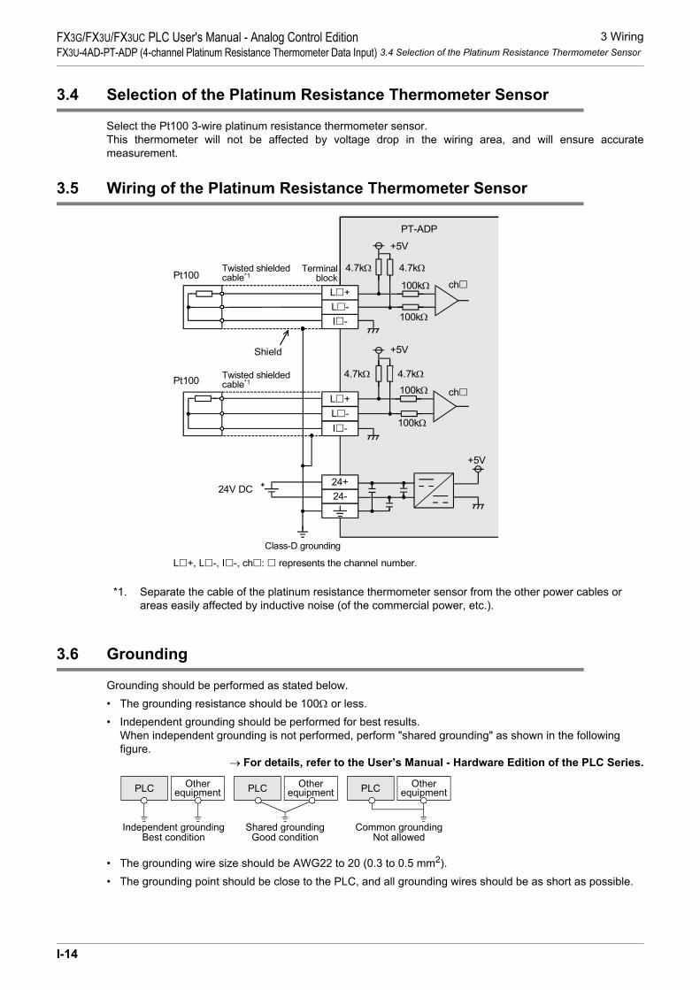
3 Wiring3.4 Selection of the Platinum Resistance Thermometer Sensor
FX3G/FX3U/FX3UC PLC User's Manual - Analog Control EditionFX3U-4AD-PT-ADP (4-channel Platinum Resistance Thermometer Data Input)
3.4 Selection of the Platinum Resistance Thermometer Sensor
Select the Pt100 3-wire platinum resistance thermometer sensor.This thermometer will not be affected by voltage drop in the wiring area, and will ensure accuratemeasurement.
3.5 Wiring of the Platinum Resistance Thermometer Sensor
*1. Separate the cable of the platinum resistance thermometer sensor from the other power cables or areas easily affected by inductive noise (of the commercial power, etc.).
3.6 Grounding
Grounding should be performed as stated below.• The grounding resistance should be 100Ω or less.• Independent grounding should be performed for best results.
When independent grounding is not performed, perform "shared grounding" as shown in the following figure.
→ For details, refer to the User’s Manual - Hardware Edition of the PLC Series.
• The grounding wire size should be AWG22 to 20 (0.3 to 0.5 mm2).• The grounding point should be close to the PLC, and all grounding wires should be as short as possible.
100kΩ
ch
PT-ADP
Class-D grounding
+5V
24+24-
Twisted shieldedcable*1
Terminalblock
24V DC
L +, L -, I -, ch : represents the channel number.
Pt100100kΩ
4.7kΩ4.7kΩ
+5V
100kΩ
ch
+5V
100kΩ
4.7kΩ4.7kΩPt100
L -I -
L +
L -I -
L +
Shield
Twisted shieldedcable*1
PLC OtherequipmentPLC Other
equipmentPLC Otherequipment
Shared groundingGood condition
Common groundingNot allowed
Independent groundingBest condition
I-14

4 Programming4.1 Loading of A/D Conversion Data
FX3G/FX3U/FX3UC PLC User's Manual - Analog Control EditionFX3U-4AD-PT-ADP (4-channel Platinum Resistance Thermometer Data Input)
A
Comm
on Items
B
FX3U-4ADFX3UC-4AD
C
FX3U-4AD-ADP
D
FX3G-2AD-BD
E
FX3U-4DA
F
FX3U-4DA-ADP
G
FX3G-1DA-BD
H
FX3U-3A-ADP
I
FX3U-4AD-PT -ADP
J
FX3U-4AD-PTW -ADP
4. Programming
This chapter describes how to create programs that can read analog data using the PT-ADP.
4.1 Loading of A/D Conversion Data
1) The input analog data will be converted into digital data and then stored in the special devices of theFX3U/FX3UC/FX3G Series PLC.
2) If data is stored in the special devices, the averaging time can be set, and the input mode can bespecified.
3) Special auxiliary relays (10 points) and special data registers (10 points) are assigned automaticallystarting from the adapter nearest to the main unit.
→ For a detailed description of special device assignment, refer to Section 4.2.• FX3U, FX3UC Series PLC
The analog special adapter nearest to the main unit is counted as the 1st analog special adapter, and the next adapter as the 2nd analog special adapter, and so on. However, in this case, do not include the high-speed input/output special adapter, communication special adapter, and the CF card special adapter.
Sequenceprogram
Special devices
A/D
A/D
A/D
A/D
Communi-cationspecialadapter
FX3U-4AD-PT-ADP
FX3U-4AD-PT-ADP
FX3U-4AD-PT-ADP
FX3U-4AD-PT-ADP FX3U/FX3UC Series PLC
1st2nd3rd4th
High-speedinput/output
specialadapter
Special auxiliary relays:M8280 to M8289
Special data registers:D8280 to D8289
Special auxiliary relays:M8270 to M8279
Special data registers:D8270 to D8279
Special auxiliary relays:M8260 to M8269
Special data registers:D8260 to D8269
Special auxiliary relays:M8290 to M8299
Special data registers:D8290 to D8299
I-15

4 Programming4.1 Loading of A/D Conversion Data
FX3G/FX3U/FX3UC PLC User's Manual - Analog Control EditionFX3U-4AD-PT-ADP (4-channel Platinum Resistance Thermometer Data Input)
• FX3G Series PLC
The analog special adapter nearest to the main unit is counted as the 1st analog special adapter, and the next adapter as the 2nd analog special adapter. However, in this case, do not include the connector conversion adapter and the communication special adapter.
*1. The second special adapter is not available in the FX3G Series PLC(14-point and 24-point type).
2nd*1 1st
Communi-
cation
special
adapter
Connector
conversion
adapter
FX3U-4AD
-PT-ADP
FX3U-4AD
-PT-ADP
Sequence
Program
FX3G Series PLC
Special devices
Special auxiliary relays:
M8280 to M8289
Special data registers:
D8280 to D8289
Special auxiliary relays:
M8290 to M8299
Special data registers:
D8290 to D8299
A/D
A/D
I-16

4 Programming4.2 List of Special Devices
FX3G/FX3U/FX3UC PLC User's Manual - Analog Control EditionFX3U-4AD-PT-ADP (4-channel Platinum Resistance Thermometer Data Input)
A
Comm
on Items
B
FX3U-4ADFX3UC-4AD
C
FX3U-4AD-ADP
D
FX3G-2AD-BD
E
FX3U-4DA
F
FX3U-4DA-ADP
G
FX3G-1DA-BD
H
FX3U-3A-ADP
I
FX3U-4AD-PT -ADP
J
FX3U-4AD-PTW -ADP
4.2 List of Special Devices
If the PT-ADP is connected, special devices will be assigned automatically as shown in the following table:• FX3U, FX3UC Series PLC
R: Read / W: Write
Special device
Device numberDescription Attribute Reference
1st 2nd 3rd 4th
Special auxiliary
relay
M8260 M8270 M8280 M8290 Selects the temperature unit. R/W Section 4.3
M8261 to M8269
M8271 to M8279
M8281 to M8289
M8291 to M8299 Unused (Do not use.) - -
Specialdata
register
D8260 D8270 D8280 D8290 Channel-1 temperature measurement data R
Section 4.4
D8261 D8271 D8281 D8291 Channel-2 temperature measurement data R
D8262 D8272 D8282 D8292 Channel-3 temperature measurement data R
D8263 D8273 D8283 D8293 Channel-4 temperature measurement data R
D8264 D8274 D8284 D8294 Averaging time for channel 1 (Setting range: 1 to 4095) R/W
Section 4.5
D8265 D8275 D8285 D8295 Averaging time for channel 2 (Setting range: 1 to 4095) R/W
D8266 D8276 D8286 D8296 Averaging time for channel 3 (Setting range: 1 to 4095) R/W
D8267 D8277 D8287 D8297 Averaging time for channel 4 (Setting range: 1 to 4095) R/W
D8268 D8278 D8288 D8298 Error status R/W Section 4.6
D8269 D8279 D8289 D8299 Model code = 20 R Section 4.7
I-17

4 Programming4.3 Selection of Temperature Unit
FX3G/FX3U/FX3UC PLC User's Manual - Analog Control EditionFX3U-4AD-PT-ADP (4-channel Platinum Resistance Thermometer Data Input)
• FX3G Series PLCR: Read / W: Write
4.3 Selection of Temperature Unit
To switch the temperature unit of the PT-ADP turn the special auxiliary relay ON for Fahrenheit (°F) or OFFfor Centigrade (°C).To switch the temperature unit, use the following special auxiliary relays:• FX3U, FX3UC Series PLC
• FX3G Series PLC
1. Program Example (For FX3U, FX3UC Series PLC)
Special deviceDevice number
Description Attribute Reference1st 2nd
Special auxiliary relayM8280 M8290 Selects the temperature unit. R/W Section 4.3
M8281 to M8289
M8291 to M8299 Unused (Do not use.) - -
Special data register
D8280 D8290 Channel-1 temperature measurement data R
Section 4.4D8281 D8291 Channel-2 temperature
measurement data R
D8282 D8292 Channel-3 temperature measurement data R
D8283 D8293 Channel-4 temperature measurement data R
D8284 D8294 Averaging time for channel 1 (Setting range: 1 to 4095) R/W
Section 4.5D8285 D8295 Averaging time for channel 2
(Setting range: 1 to 4095) R/W
D8286 D8296 Averaging time for channel 3 (Setting range: 1 to 4095) R/W
D8287 D8297 Averaging time for channel 4 (Setting range: 1 to 4095) R/W
D8288 D8298 Error status R/W Section 4.6D8289 D8299 Model code = 20 R Section 4.7
Special auxiliary relayDescription
1st 2nd 3rd 4th
M8260 M8270 M8280 M8290Selection of temperature unit:OFF: Centigrade (°C)ON: Fahrenheit (°F)
Special auxiliary relayDescription
1st 2nd
M8280 M8290Selection of temperature unit:OFF: Centigrade (°C)ON: Fahrenheit (°F)
1) To switch the temperature unit to centigrade (°C) for the 1st adapter:
M8001M8260
Normally OFF
2) To switch the temperature unit to Fahrenheit (°F) for the 2nd adapter:
M8000M8270
Normally ON
I-18

4 Programming4.4 Temperature Measurement
FX3G/FX3U/FX3UC PLC User's Manual - Analog Control EditionFX3U-4AD-PT-ADP (4-channel Platinum Resistance Thermometer Data Input)
A
Comm
on Items
B
FX3U-4ADFX3UC-4AD
C
FX3U-4AD-ADP
D
FX3G-2AD-BD
E
FX3U-4DA
F
FX3U-4DA-ADP
G
FX3G-1DA-BD
H
FX3U-3A-ADP
I
FX3U-4AD-PT -ADP
J
FX3U-4AD-PTW -ADP
4.4 Temperature Measurement
The temperature data input in the PT-ADP will be stored in the special data registers.The special data registers that store the temperature data are shown in the following table:• FX3U, FX3UC Series PLC
• FX3G Series PLC
The immediate data or the average data (data averaged in accordance with the specified averaging time) will be stored in the above data registers as the temperature measurement data.
→ For a detailed description of the averaging time, refer to Section 4.6.
1. Caution regarding temperature measurementThe special data registers for temperature measurement data are for reading only.Do not change (rewrite) the current data using the sequence program, indicator, or device monitor of theprogramming tool.
2. Program Example (For FX3U, FX3UC Series PLC)
Even if the temperature measurement data is not stored in the D100 or the D101, the D8260 or the D8261can be directly used in the arithmetic operation instruction or a PID instruction.
Special data registerDescription
1st 2nd 3rd 4thD8260 D8270 D8280 D8290 Stores the channel-1 temperature measurement data.
D8261 D8271 D8281 D8291 Stores the channel-2 temperature measurement data.
D8262 D8272 D8282 D8292 Stores the channel-3 temperature measurement data.
D8263 D8273 D8283 D8293 Stores the channel-4 temperature measurement data.
Special data registerDescription
1st 2ndD8280 D8290 Stores the channel-1 temperature measurement data.
D8281 D8291 Stores the channel-2 temperature measurement data.
D8282 D8292 Stores the channel-3 temperature measurement data.
D8283 D8293 Stores the channel-4 temperature measurement data.
M8000
NormallyON
FNC 12MOV
D8260 D100
FNC 12MOV
D8261 D101
Stores the channel-1 temperature measurementdata of the 1st analog special adapter in D100.
Stores the channel-2 temperature measurementdata of the 1st analog special adapter in D101.
I-19

4 Programming4.5 Averaging Time
FX3G/FX3U/FX3UC PLC User's Manual - Analog Control EditionFX3U-4AD-PT-ADP (4-channel Platinum Resistance Thermometer Data Input)
4.5 Averaging Time
Setting range: 1 to 4095Initial value: K1
Numeric data type: Decimal (K)If the averaging time is set for the PT-ADP, the averaged temperature measurement data will be stored in theD8260 to D8263, D8270 to D8273, D8280 to D8283, and D8290 to D8293. The averaging time can be set foreach channel.Set the averaging time in the following special data registers:• FX3U, FX3UC Series PLC
• FX3G Series PLC
1. Cautions regarding averaging time setting• If the averaging time is set to "1", the immediate data will be stored in the temperature measurement
special data register.• If the averaging time is set to "2" or more, the average value will be calculated in accordance with the set
averaging time, and the average value obtained will be stored in the temperature measurement special data register.
• After turning the PLC power on, the average data will be stored in the temperature measurement special data registers (D8260 to D8263, D8270 to D8273, D8280 to D8283, and D8290 to D8293) until the number of data items is increased to the set averaging time.
• Set the averaging time in the range from 1 to 4095. If the set value is outside the setting range, the error signal will be output.
• If the averaging time is set to "0" or smaller, the PLC will perform as if the averaging time is set to "1".If the averaging time is set to "4096" or larger, the PLC will perform as if the averaging time is set to "4096".
→ For a detailed description of error status, refer to Section 5.5
2. Program Example (For FX3U, FX3UC Series PLC)
Special data registerDescription
1st 2nd 3rd 4thD8264 D8274 D8284 D8294 Averaging time for channel-1 data
D8265 D8275 D8285 D8295 Averaging time for channel-2 data
D8266 D8276 D8286 D8296 Averaging time for channel-3 data
D8267 D8277 D8287 D8297 Averaging time for channel-4 data
Special data registerDescription
1st 2ndD8284 D8294 Averaging time for channel-1 data
D8285 D8295 Averaging time for channel-2 data
D8286 D8296 Averaging time for channel-3 data
D8287 D8297 Averaging time for channel-4 data
M8000
NormallyON
FNC 12MOV
K1 D8264
FNC 12MOV
K5 D8265
Sets the averaging time to "1" for the channel-1data of the 1st analog special adapter.
Sets the averaging time to "5" for the channel-2data of the 1st analog special adapter.
I-20

4 Programming4.6 Error Status
FX3G/FX3U/FX3UC PLC User's Manual - Analog Control EditionFX3U-4AD-PT-ADP (4-channel Platinum Resistance Thermometer Data Input)
A
Comm
on Items
B
FX3U-4ADFX3UC-4AD
C
FX3U-4AD-ADP
D
FX3G-2AD-BD
E
FX3U-4DA
F
FX3U-4DA-ADP
G
FX3G-1DA-BD
H
FX3U-3A-ADP
I
FX3U-4AD-PT -ADP
J
FX3U-4AD-PTW -ADP
4.6 Error Status
If an error is detected in the PT-ADP, the error status data will be stored in the corresponding special dataregister.The following table shows the special data registers that store the error status data:• FX3U, FX3UC Series PLC
• FX3G Series PLC
Check the ON/OFF status of each bit of the error status data register to determine the error. Errors are assigned to the bits as shown in the following table. Create a program to detect errors.
1. Caution regarding use of error status dataIf a PT-ADP hardware error (b6) or PT-ADP communication data error (b7) is detected, it is necessary to clear the error status with a program at the next power-on of the PLC.For this reason, be sure to create the following program:• For FX3G, FX3U, FX3UC Series PLC
*1. "1st" for the FX3G PLC.
Special data registerDescription
1st 2nd 3rd 4thD8268 D8278 D8288 D8298 Stores the error status data.
Special data registerDescription
1st 2ndD8288 D8298 Stores the error status data.
Bit Description Bit Description
b0The temperature measurement data of channel 1 is outside the specified range, or disconnection is detected.
b5 Averaging time setting error
b1The temperature measurement data of channel 2 is outside the specified range, or disconnection is detected.
b6 PT-ADP hardware error
b2The temperature measurement data of channel 3 is outside the specified range, or disconnection is detected.
b7 PT-ADP communication data error
b3The temperature measurement data of channel 4 is outside the specified range, or disconnection is detected.
b8 to b15 Unused
b4 EEPROM error - -
Error status of 3rd*1 analog special adapterb6 = OFF (hardware error)
Error status of 3rd*1 analog special adapterb7 = OFF (communication data error)
M8002
Normally
ON
Initial pulse
RST M6
RST M7
M8000MOV D8288 K4M0
MOV K4M0 D8288
I-21

4 Programming4.6 Error Status
FX3G/FX3U/FX3UC PLC User's Manual - Analog Control EditionFX3U-4AD-PT-ADP (4-channel Platinum Resistance Thermometer Data Input)
• For FX3U, FX3UC Series PLC
2. Program Example 1 (For FX3G, FX3U, FX3UC Series PLC)
*1. "1st" for the FX3G PLC.
Error status of 1st analog special adapterb6 = OFF (hardware error)
Error status of 1st analog special adapterb7 = OFF (communication data error)
M8002
Initial pulseRST D8268.6
RST D8268.7
Y000M0
M1
M2
M3
M4
M5
M6
M7
Y001
Y002
Y003
Y004 EEPROM error in 3rd*1 adapter
Y005
Y006
Y007
Averaging time setting error in 3rd*1
adapter
PT-ADP hardware error in 3rd*1
adapter
PT-ADP communication data error in3rd*1 adapter
The temperature measurement data
of channel 1 is outside the specified
range, or disconnection is detected.
The temperature measurement data
of channel 2 is outside the specified
range, or disconnection is detected.
The temperature measurement data
of channel 3 is outside the specified
range, or disconnection is detected.
The temperature measurement data
of channel 4 is outside the specified
range, or disconnection is detected.
M8000MOV D8288 K4M0
I-22

4 Programming4.6 Error Status
FX3G/FX3U/FX3UC PLC User's Manual - Analog Control EditionFX3U-4AD-PT-ADP (4-channel Platinum Resistance Thermometer Data Input)
A
Comm
on Items
B
FX3U-4ADFX3UC-4AD
C
FX3U-4AD-ADP
D
FX3G-2AD-BD
E
FX3U-4DA
F
FX3U-4DA-ADP
G
FX3G-1DA-BD
H
FX3U-3A-ADP
I
FX3U-4AD-PT -ADP
J
FX3U-4AD-PTW -ADP
3. Program Example 2 (For FX3U, FX3UC Series PLC)
Y000D8268.0
Y001D8268.1
Y002D8268.2
Y003D8268.3
Y004D8268.4
EEPROM error in 1st adapter
Y005D8268.5
Y006D8268.6
Y007D8268.7
Averaging time setting error in 1stadapter
PT-ADP hardware error in 1stadapter
PT-ADP communication data error in1st adapter
The temperature measurement dataof channel 1 is outside the specifiedrange, or disconnection is detected.
The temperature measurement dataof channel 2 is outside the specifiedrange, or disconnection is detected.
The temperature measurement dataof channel 3 is outside the specifiedrange, or disconnection is detected.
The temperature measurement dataof channel 4 is outside the specifiedrange, or disconnection is detected.
I-23

4 Programming4.7 Model Code
FX3G/FX3U/FX3UC PLC User's Manual - Analog Control EditionFX3U-4AD-PT-ADP (4-channel Platinum Resistance Thermometer Data Input)
4.7 Model Code
Initial value: K20Numeric data type: Decimal (K)
When the PT-ADP is connected, model code "20" will be stored in the corresponding special data register.The following table shows the special data registers that store the model code:• FX3U, FX3UC Series PLC
• FX3G Series PLC
Use the special data registers above to check whether PT-ADP is connected or not.
1. Program Example (For FX3U, FX3UC Series PLC)
Special data registerDescription
1st 2nd 3rd 4thD8269 D8279 D8289 D8299 Model code
Special data registerDescription
1st 2ndD8289 D8299 Model code
FNC224LD =
D8269 K20 Checks the model code of the 1stanalog special adapter.Y010
I-24

4 Programming4.8 Basic Program Example
FX3G/FX3U/FX3UC PLC User's Manual - Analog Control EditionFX3U-4AD-PT-ADP (4-channel Platinum Resistance Thermometer Data Input)
A
Comm
on Items
B
FX3U-4ADFX3UC-4AD
C
FX3U-4AD-ADP
D
FX3G-2AD-BD
E
FX3U-4DA
F
FX3U-4DA-ADP
G
FX3G-1DA-BD
H
FX3U-3A-ADP
I
FX3U-4AD-PT -ADP
J
FX3U-4AD-PTW -ADP
4.8 Basic Program Example
Create the following basic program example to read out the temperature measurement data.• For FX3G, FX3U, FX3UC Series PLCThe following program will store the temperature measurement data (°C) from channels 1 and 2 of the 3rd*1 adapter to D100 and D101, respectively. The averaging time is set to "1" (immediate data) for channel 1, and "5" for channel 2.
Even if the temperature measurement data is not stored in D100 or D101, data register D8280 or D8281 canbe directly used in the arithmetic operation instruction or a PID instruction.
*1. "1st" for the FX3G PLC.• For FX3U, FX3UC Series PLCThe following program will store the temperature measurement data (°C) from channels 1 and 2 of the 1stadapter to D100 and D101, respectively. The averaging time is set to "1" (immediate data) for channel 1, and"5" for channel 2.
Even if the temperature measurement data is not stored in D100 or D101, data register D8260 or D8261 canbe directly used in the arithmetic operation instruction or a PID instruction.
M8002
M8001
M8280Sets the temperature unit to centigrade(°C).
M8002FNC 12
MOVK1 D8284
FNC 12MOV
K5 D8285
Sets the averaging time to "1" forchannel-1 data.
Sets the averaging time to "5" forchannel-2 data.
RST M6
RST M7
Error status of 3rd*1 analog specialadapterb6 = OFF (hardware error)
Error status of 3rd*1 analog specialadapterb7 = OFF (communication data error)
M8000FNC 12
MOVD8280 D100
FNC 12MOV
D8281 D101
Stores the current value of the channel-1temperature measurement data in the D100.
Stores the average value of the channel-2temperature measurement data in the D101.
Initial
pulse
M8000MOV D8288 K4M0
MOV K4M0 D8288
M8002
M8001M8260 Sets the temperature unit to centigrade
(°C).
M8002FNC 12
MOVK1 D8264
FNC 12MOV
K5 D8265
Sets the averaging time to "1" forchannel-1 data.
Sets the averaging time to "5" forchannel-2 data.
RST D8268.6
RST D8268.7
Error status of 1st analog specialadapterb6 = OFF (hardware error)
Error status of 1st analog specialadapterb7 = OFF (communication data error)
M8000FNC 12
MOVD8260 D100
FNC 12MOV
D8261 D101
Stores the current value of the channel-1temperature measurement data in the D100.
Stores the average value of the channel-2temperature measurement data in the D101.
I-25

5 Troubleshooting5.1 PLC Version Number Check
FX3G/FX3U/FX3UC PLC User's Manual - Analog Control EditionFX3U-4AD-PT-ADP (4-channel Platinum Resistance Thermometer Data Input)
5. Troubleshooting
This chapter describes the troubleshooting methods and error status.If the temperature measurement data is not input, or if the proper digital value is not input, check the followingitems:• Version number of the PLC• Wiring• Special devices• Programs• Error status
5.1 PLC Version Number Check
• Any versions (from Ver.2.20 (initial version) to the latest version) of the FX3U Series are compatible.• Check the version number of the FX3UC Series. The version number should be 1.30 or later.• Any versions (from Ver.1.00 (initial version) to the latest version) of the FX3G Series are compatible.
→ For a detailed description of the version number check method, refer to Section 1.3.
5.2 Wiring Check
Check the following items for wiring:
1. PowerThe PT-ADP needs driving power. Verify that the power supply line is properly connected. Also check that the POWER indicator lamp of the PT-ADP is on.
2. Platinum resistance thermometer sensor cableSeparate the cable of the platinum resistance thermometer from other power cables or inductive cables.
→ For a detailed description of wiring, refer to Chapter 3.
5.3 Special Device Check
Check whether the special devices for the PT-ADP are correctly used:
1. Temperature measurementVerify that the special device for the selected channel is correctly selected. This special device should beselected depending on the connecting position and the channel.
2. Averaging timeCheck that the set averaging time is within the specified range. The averaging time should be set in the rangefrom 1 to 4095. If the set averaging time is outside the specified range, an error occurs.
3. Error statusCheck that no error is detected in the PT-ADP.If an error is detected, check the details of the error, and then check the wiring and programs.
→ For a detailed description of special devices, refer to Chapter 4.
I-26

5 Troubleshooting5.4 Program Check
FX3G/FX3U/FX3UC PLC User's Manual - Analog Control EditionFX3U-4AD-PT-ADP (4-channel Platinum Resistance Thermometer Data Input)
A
Comm
on Items
B
FX3U-4ADFX3UC-4AD
C
FX3U-4AD-ADP
D
FX3G-2AD-BD
E
FX3U-4DA
F
FX3U-4DA-ADP
G
FX3G-1DA-BD
H
FX3U-3A-ADP
I
FX3U-4AD-PT -ADP
J
FX3U-4AD-PTW -ADP
5.4 Program Check
Check the following items for the program:
1. Cancellation of error status at power-onWhen the power is turned off and then on again, the error status should be cleared (b6 and b7 should turn off)using the program.
2. Check of storage devicesVerify that different values are not being stored in the same device by the other parts of the programs.
5.5 Error Status Check
If an error occurs in the PT-ADP, the corresponding bit will turn on.The bit which is turned ON due to the error status is held ON until overwritten to OFF by the program or thepower is cycled. If b6 or b7 is turned ON, then it is necessary to clear the error status using the program thenext time the power of the PLC is cycled.
To solve a problem, refer to the troubleshooting method described below:
1. Temperature measurement out of specified range or disconnection of line (b0 to b3)1) Description of error
The input temperature measurement value is outside the specified range.The temperature measurement value is not in the range between -55°C to 255°C.Or the line between PT-ADP and the platinum resistance thermometer sensor is disconnected.
2) RemedyCheck that the input temperature measurement value is within the specified range. Also check the wiringcondition.
2. EEPROM error (b4)1) Description of error
The adjustment data set in the EEPROM before delivery from our factory cannot be read out properly oris destroyed.
2) RemedyPlease contact the nearest Mitsubishi Electric distributor office.
3. Averaging time setting error (b5)1) Description of error
The averaging time set for one of the channels (channels 1 to 4) is outside the specified range: 1 to 4095.
2) RemedyCheck that the averaging time is correctly set for each channel.
Bit Description Bit Description
b0The temperature measurement data of channel 1 is outside the specified range, or disconnection is detected.
b5 Averaging time setting error
b1The temperature measurement data of channel 2 is outside the specified range, or disconnection is detected.
b6 PT-ADP hardware error
b2The temperature measurement data of channel 3 is outside the specified range, or disconnection is detected.
b7 PT-ADP communication data error
b3The temperature measurement data of channel 4 is outside the specified range, or disconnection is detected.
b8 to 15 Unused
b4 EEPROM error - -
I-27

5 Troubleshooting5.5 Error Status Check
FX3G/FX3U/FX3UC PLC User's Manual - Analog Control EditionFX3U-4AD-PT-ADP (4-channel Platinum Resistance Thermometer Data Input)
4. PT-ADP hardware error (b6)1) Description of error
The PT-ADP does not operate properly.2) Remedy
Check that the 24V DC power is properly supplied to the PT-ADP. Also check that the PT-ADP is correctly connected to the PLC.If the problem cannot be solved even after the above check, please contact the nearest Mitsubishi Electric distributor office.
5. PT-ADP communication data error (b7)1) Description of error
A communication error is detected between the PT-ADP and the PLC.2) Remedy
Check that the PT-ADP is correctly connected to the PLC.If the problem cannot be solved even after the above check, please contact the nearest Mitsubishi Electric distributor office.
I-28

A
Comm
on Items
B
FX3U-4ADFX3UC-4AD
C
FX3U-4AD-ADP
D
FX3G-2AD-BD
E
FX3U-4DA
F
FX3U-4DA-ADP
G
FX3G-1DA-BD
H
FX3U-3A-ADP
I
FX3U-4AD-PT -ADP
J
FX3U-4AD-PTW -ADP
FX3G/FX3U/FX3UC PLC User's Manual - Analog Control EditionFX3U-4AD-PTW-ADP (4-channel Platinum Resistance Thermometer Data Input)
FX3G/FX3U/FX3UC Series Programmable Controllers
User's Manual [Analog Control Edition] FX3U-4AD-PTW-ADP (4-channel Platinum Resistance Thermometer Data Input)
Foreword
This manual describes the specifications, wiring, and operation methods for the FX3U-4AD-PTW-ADP special adapter (4-channel platinum resistance thermometer input) and should be read and understood before attempting to install or use the unit.Store this manual in a safe place so that you can take it out and read it whenever necessary. Always forward it to the end user.
© 2005 MITSUBISHI ELECTRIC CORPORATION
This manual confers no industrial property rights or any rights of any other kind, nor does it confer any patentlicenses. Mitsubishi Electric Corporation cannot be held responsible for any problems involving industrial propertyrights which may occur as a result of using the contents noted in this manual.
J-1

FX3G/FX3U/FX3UC PLC User's Manual - Analog Control EditionFX3U-4AD-PTW-ADP (4-channel Platinum Resistance Thermometer Data Input)
J-2

1 Outline1.1 Outline of Functions
FX3G/FX3U/FX3UC PLC User's Manual - Analog Control EditionFX3U-4AD-PTW-ADP (4-channel Platinum Resistance Thermometer Data Input)
A
Comm
on Items
B
FX3U-4ADFX3UC-4AD
C
FX3U-4AD-ADP
D
FX3G-2AD-BD
E
FX3U-4DA
F
FX3U-4DA-ADP
G
FX3G-1DA-BD
H
FX3U-3A-ADP
I
FX3U-4AD-PT -ADP
J
FX3U-4AD-PTW -ADP
1. Outline
This chapter describes the outline of FX3U-4AD-PTW-ADP (referred to as PTW-ADP).
1.1 Outline of Functions
The FX3U-4AD-PTW-ADP is an analog special adapter. Connect the FX3U-4AD-PTW-ADP to the FX3U/FX3UC/FX3G Series PLC to read the temperature data from the 4-channel platinum resistance thermometers.1) Up to 4 PTW-ADP units can be connected to the FX3U/FX3UC Series PLC.
Up to 2*1 PTW-ADP units can be connected to the FX3G Series PLC.(including other analog special adapters)
2) After connection of the platinum resistance thermometer (Pt100), measurement of temperature will bepossible.
3) The temperature measurement data will be automatically written to the special data registers of the FX3U/FX3UC/FX3G Series PLC.
Number of connectable
units
……For a detaileddescription of wiring,refer to Chapter 3.
……To check the connectablePLC model number, referto Section 1.3.
Point and section to bereferred to
System
……
Special devices ……For a detailed descriptionof special devices, refer toChapter 4.
For a detailed descriptionof a basic program, refer toSection 4.8.
Analog data
Refer to the system configuration shown in the User's Manual - Hardware Edition to check the number of connectable unitsand to configure the entire system.
*2. The expansion board is not required when connecting with the FX
For the FX3G Series PLC a connector conversion adapter is used.
3UC (D, DSS) PLC.
FX3U, FX3UC Series PLC : 4 maximum
FX3G Series PLC : 2*1 maximum(including other analog special adapters)
1st adapter M/D8260 to M/D8269
M/D8270 to M/D8279
M/D8280 to M/D8289
M/D8290 to M/D8299
2nd adapter
3rd adapter
4th adapter
++
Expansionboard*2
FX3U/FX3UC/FX3G Series PLC
For FX3U, FX3UC
Series PLC
4thadapter
3rdadapter
2ndadapter
1stadapter
Transfer direction
*1. Only 1 analog special adapter can be connected to the 14-point and 24-point type main unit.
Platinum resistance thermometersensor(Pt100)
Description
Measurementtemperature
Setting of temperatureunit
Setting of averaging time
J-3

1 Outline1.2 Setup Procedure Before Starting Operation
FX3G/FX3U/FX3UC PLC User's Manual - Analog Control EditionFX3U-4AD-PTW-ADP (4-channel Platinum Resistance Thermometer Data Input)
1.2 Setup Procedure Before Starting Operation
Before starting analog input using the PTW-ADP, follow the procedure below to set up the system:
Specifications:•Operation environment•Performance specifications•Input characteristics
Specifications check
Refer to Chapter 2.
System configuration and selection
Wiring
Refer to Chapter 3.
FX3U-4AD-PTW-ADP
System configuration: (Refer to the common pages for analog control.)•Selection of units
Refer to the commonpages.
Wiring:•Power supply line•Platinum resistance thermometer sensor line
Outline of system:•Compatible PLC version number•Compatible programming tool version number
Outline
Refer to Chapter 1.
Programming
Refer to Chapter 4.
Programming:•Details of special devices•Examples of basic programs
If the error status data or the input digital value isabnormal, refer to Chapter 5 "Troubleshooting."
J-4
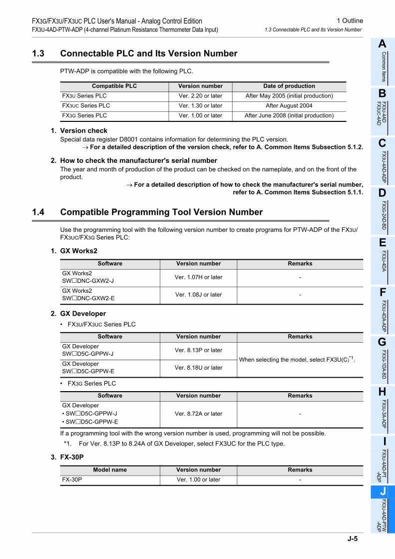
1 Outline1.3 Connectable PLC and Its Version Number
FX3G/FX3U/FX3UC PLC User's Manual - Analog Control EditionFX3U-4AD-PTW-ADP (4-channel Platinum Resistance Thermometer Data Input)
A
Comm
on Items
B
FX3U-4ADFX3UC-4AD
C
FX3U-4AD-ADP
D
FX3G-2AD-BD
E
FX3U-4DA
F
FX3U-4DA-ADP
G
FX3G-1DA-BD
H
FX3U-3A-ADP
I
FX3U-4AD-PT -ADP
J
FX3U-4AD-PTW -ADP
1.3 Connectable PLC and Its Version Number
PTW-ADP is compatible with the following PLC.
1. Version checkSpecial data register D8001 contains information for determining the PLC version.
→ For a detailed description of the version check, refer to A. Common Items Subsection 5.1.2.
2. How to check the manufacturer's serial numberThe year and month of production of the product can be checked on the nameplate, and on the front of the product.
→ For a detailed description of how to check the manufacturer's serial number,refer to A. Common Items Subsection 5.1.1.
1.4 Compatible Programming Tool Version Number
Use the programming tool with the following version number to create programs for PTW-ADP of the FX3U/FX3UC/FX3G Series PLC:
1. GX Works2
2. GX Developer• FX3U/FX3UC Series PLC
• FX3G Series PLC
If a programming tool with the wrong version number is used, programming will not be possible.*1. For Ver. 8.13P to 8.24A of GX Developer, select FX3UC for the PLC type.
3. FX-30P
Compatible PLC Version number Date of productionFX3U Series PLC Ver. 2.20 or later After May 2005 (initial production)
FX3UC Series PLC Ver. 1.30 or later After August 2004
FX3G Series PLC Ver. 1.00 or later After June 2008 (initial production)
Software Version number RemarksGX Works2SW DNC-GXW2-J Ver. 1.07H or later -
GX Works2SW DNC-GXW2-E Ver. 1.08J or later -
Software Version number RemarksGX DeveloperSW D5C-GPPW-J Ver. 8.13P or later
When selecting the model, select FX3U(C)*1.GX DeveloperSW D5C-GPPW-E Ver. 8.18U or later
Software Version number RemarksGX Developer• SW D5C-GPPW-J• SW D5C-GPPW-E
Ver. 8.72A or later -
Model name Version number RemarksFX-30P Ver. 1.00 or later -
J-5
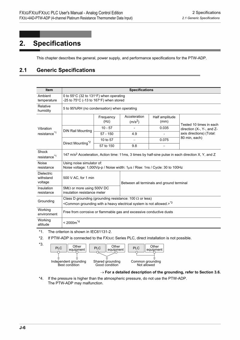
2 Specifications2.1 Generic Specifications
FX3G/FX3U/FX3UC PLC User's Manual - Analog Control EditionFX3U-4AD-PTW-ADP (4-channel Platinum Resistance Thermometer Data Input)
2. Specifications
This chapter describes the general, power supply, and performance specifications for the PTW-ADP.
2.1 Generic Specifications
*1. The criterion is shown in IEC61131-2.*2. If PTW-ADP is connected to the FX3UC Series PLC, direct installation is not possible.*3.
→ For a detailed description of the grounding, refer to Section 3.6.*4. If the pressure is higher than the atmospheric pressure, do not use the PTW-ADP.
The PTW-ADP may malfunction.
Item SpecificationsAmbient temperature
0 to 55°C (32 to 131°F) when operating -25 to 75°C (-13 to 167°F) when stored
Relative humidity 5 to 95%RH (no condensation) when operating
Vibrationresistance*1
Frequency(Hz)
Acceleration(m/s2)
Half amplitude(mm)
Tested 10 times in each direction (X-, Y-, and Z-axis directions) (Total: 80 min, each)
DIN Rail Mounting10 - 57 - 0.035
57 - 150 4.9 -
Direct Mounting*210 to 57 − 0.075
57 to 150 9.8 −
Shock resistance*1 147 m/s2 Acceleration, Action time: 11ms, 3 times by half-sine pulse in each direction X, Y, and Z
Noise resistance
Using noise simulator of:Noise voltage: 1,000Vp-p / Noise width: 1µs / Rise: 1ns / Cycle: 30 to 100Hz
Dielectric withstand voltage
500 V AC, for 1 minBetween all terminals and ground terminal
Insulation resistance
5MΩ or more using 500V DC insulation resistance meter
GroundingClass D grounding (grounding resistance: 100 Ω or less) <Common grounding with a heavy electrical system is not allowed.>*3
Workingenvironment Free from corrosive or flammable gas and excessive conductive dusts
Workingaltitude < 2000m*4
PLC OtherequipmentPLC Other
equipmentPLC Otherequipment
Shared groundingGood condition
Common groundingNot allowed
Independent groundingBest condition
J-6

2 Specifications2.2 Power Supply Specifications
FX3G/FX3U/FX3UC PLC User's Manual - Analog Control EditionFX3U-4AD-PTW-ADP (4-channel Platinum Resistance Thermometer Data Input)
A
Comm
on Items
B
FX3U-4ADFX3UC-4AD
C
FX3U-4AD-ADP
D
FX3G-2AD-BD
E
FX3U-4DA
F
FX3U-4DA-ADP
G
FX3G-1DA-BD
H
FX3U-3A-ADP
I
FX3U-4AD-PT -ADP
J
FX3U-4AD-PTW -ADP
2.2 Power Supply Specifications
2.3 Performance Specifications
Items SpecificationA/D conversion circuit driving power
24V DC +20% -15%, 50mA(It is necessary to connect a 24V DC power supply to the terminal block.)
Interface driving power5V DC, 15mA(Since the internal power is supplied from the FX Series main unit, it is notnecessary to supply the power.)
ItemsSpecifications
Centigrade (°C) Fahrenheit (°F)
Input signal 3-wire platinum resistance thermometer sensorPt100 JIS C 1604-1997
Rated temperature range -100°C to +600°C -148°F to +1112°F
Digital output -1000 to +6000 -1480 to +11120
Resolution 0.2°C to 0.3°C 0.4°F to 0.5°F
Total accuracy• ±0.5% for full scale (when ambient temperature is 25°C±5°C)• ±1.0% for full scale (when ambient temperature is in the range from 0 to 55°C)
A/D conversion time
• FX3U/FX3UC Series PLC : 200µs (The data will be updated at every scan time.)• FX3G Series PLC : 250µs (The data will be updated at every scan time.)
→For a detailed description of data update, refer to Section 2.4.
Input characteristics
Insulation method
• The photocoupler is used to insulate the analog input area from the PLC.• The DC/DC converter is used to insulate the power supply line from the analog input
area.• Channels are not insulated from each other.
Number of I/O points occupied
0 points(This number is not related to the maximum number of input/output points of the PLC.)
0+600°C
+6000
-100°C
-1000-115
°C
+615
°C
+6150
-1150
0+1112°F
+11120
-148°F
-1480-175
°F
+113
9°F
-1750
+11390
J-7

2 Specifications2.4 A/D Conversion Time
FX3G/FX3U/FX3UC PLC User's Manual - Analog Control EditionFX3U-4AD-PTW-ADP (4-channel Platinum Resistance Thermometer Data Input)
2.4 A/D Conversion Time
This section describes the A/D conversion time.
2.4.1 When connected to a FX3U, FX3UC PLC
1. A/D conversion and special data register update timingA/D conversion is performed at every scan time of the PLC.During execution of END instruction, the PLC performs A/D conversion, reads out the A/D converted data,and then writes the data in the special data registers.
2. A/D conversion during PLC stopEven if the PLC is stopped, A/D conversion will be performed and the special data registers will be updated.
3. If two or more analog special adapters are connectedDuring execution of the END instruction, data will be read out from all the connected adapters (in the order of 1st adapter → 2nd adapter … 4th adapter).
4. A/D conversion speed (data update time)During execution of the END instruction, the A/D converted data of all 4 channels will be read out in 200µs, and the data read out will be written to the special data registers.END instruction execution time will be "200µs × number of connected adapters."
FX3U/FX3UC Series PLCFX3U-4AD-PTW-ADP
1stFX3U-4AD-PTW-ADP
n'th
A/Dconversion
200µs/4ch
A/Dconversion
200µs/4ch
Digital value reading
A/D conversion startcommand
END instruction
Sequenceprogram
Digital value reading
A/D conversion startcommand
J-8

2 Specifications2.5 Temperature Measurement
FX3G/FX3U/FX3UC PLC User's Manual - Analog Control EditionFX3U-4AD-PTW-ADP (4-channel Platinum Resistance Thermometer Data Input)
A
Comm
on Items
B
FX3U-4ADFX3UC-4AD
C
FX3U-4AD-ADP
D
FX3G-2AD-BD
E
FX3U-4DA
F
FX3U-4DA-ADP
G
FX3G-1DA-BD
H
FX3U-3A-ADP
I
FX3U-4AD-PT -ADP
J
FX3U-4AD-PTW -ADP
2.4.2 When connected to a FX3G PLC
1. A/D conversion and special data register update timingA/D conversion is performed at every scan time of the PLC.During execution of END instruction, the PLC performs A/D conversion, reads out the A/D converted data,and then writes the data in the special data registers.
2. A/D conversion during PLC stopEven if the PLC is stopped, A/D conversion will be performed and the special data registers will be updated.
3. If two analog special adapters are connectedDuring execution of the END instruction, data will be read out from all the connected adapters (in the order of 1st adapter → 2nd adapter).
4. A/D conversion speed (data update time)During execution of the END instruction, the A/D converted data of all 4 channels will be read out in 250µs, and the data read out will be written to the special data registers.END instruction execution time will be "250µs × number of connected adapters."
2.5 Temperature Measurement
To stabilize the temperature measurement, warm-up the system for 30 minutes or more after power-on.
FX3G Series PLCFX3U-4AD-PTW-ADP
1stFX3U-4AD-PTW-ADP
2nd
A/Dconversion
250µs/4ch
A/Dconversion
250µs/4ch
Digital value reading
A/D conversion startcommand
END instruction
Sequenceprogram
Digital value reading
A/D conversion startcommand
J-9
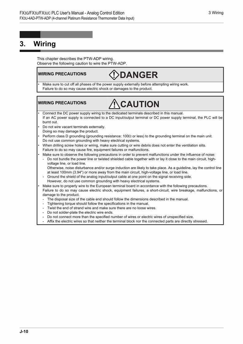
3 WiringFX3G/FX3U/FX3UC PLC User's Manual - Analog Control EditionFX3U-4AD-PTW-ADP (4-channel Platinum Resistance Thermometer Data Input)
3. Wiring
This chapter describes the PTW-ADP wiring.Observe the following caution to wire the PTW-ADP.
WIRING PRECAUTIONS
• Make sure to cut off all phases of the power supply externally before attempting wiring work.Failure to do so may cause electric shock or damages to the product.
WIRING PRECAUTIONS
• Connect the DC power supply wiring to the dedicated terminals described in this manual.If an AC power supply is connected to a DC input/output terminal or DC power supply terminal, the PLC will beburnt out.
• Do not wire vacant terminals externally.Doing so may damage the product.
• Perform class D grounding (grounding resistance: 100Ω or less) to the grounding terminal on the main unit.Do not use common grounding with heavy electrical systems.
• When drilling screw holes or wiring, make sure cutting or wire debris does not enter the ventilation slits.Failure to do so may cause fire, equipment failures or malfunctions.
• Make sure to observe the following precautions in order to prevent malfunctions under the influence of noise:- Do not bundle the power line or twisted shielded cable together with or lay it close to the main circuit, high-
voltage line, or load line.Otherwise, noise disturbance and/or surge induction are likely to take place. As a guideline, lay the control line at least 100mm (3.94") or more away from the main circuit, high-voltage line, or load line.
- Ground the shield of the analog input/output cable at one point on the signal receiving side. However, do not use common grounding with heavy electrical systems.
• Make sure to properly wire to the European terminal board in accordance with the following precautions.Failure to do so may cause electric shock, equipment failures, a short-circuit, wire breakage, malfunctions, ordamage to the product.- The disposal size of the cable end should follow the dimensions described in the manual.- Tightening torque should follow the specifications in the manual.- Twist the end of strand wire and make sure there are no loose wires. - Do not solder-plate the electric wire ends.- Do not connect more than the specified number of wires or electric wires of unspecified size.- Affix the electric wires so that neither the terminal block nor the connected parts are directly stressed.
J-10

3 Wiring3.1 Terminal Layout
FX3G/FX3U/FX3UC PLC User's Manual - Analog Control EditionFX3U-4AD-PTW-ADP (4-channel Platinum Resistance Thermometer Data Input)
A
Comm
on Items
B
FX3U-4ADFX3UC-4AD
C
FX3U-4AD-ADP
D
FX3G-2AD-BD
E
FX3U-4DA
F
FX3U-4DA-ADP
G
FX3G-1DA-BD
H
FX3U-3A-ADP
I
FX3U-4AD-PT -ADP
J
FX3U-4AD-PTW -ADP
3.1 Terminal Layout
The terminals of the PTW-ADP are arranged as follows:
Signal Application
External power
Channel-1 platinumresistance thermometersensor input
Channel-3 platinumresistance thermometersensor input
Channel-4 platinumresistance thermometersensor input
Channel-2 platinumresistance thermometersensor input
24+24-
L1-I1-L2+
L3-I3-L4+
I4-
L1+
L2-I2-L3+
L4-
Ground terminal
24+
24-
L1+
L1-
I1-
L2+
L2-
I2-
L3+
L3-
I3-
L4+
L4-
I4-
FX3U-4AD-PTW-ADP
POWER
J-11

3 Wiring3.2 Applicable Cable and Terminal Tightening Torque
FX3G/FX3U/FX3UC PLC User's Manual - Analog Control EditionFX3U-4AD-PTW-ADP (4-channel Platinum Resistance Thermometer Data Input)
3.2 Applicable Cable and Terminal Tightening Torque
Use the following cables to connect with the counterpart equipment. Terminate the cable end as shown below.To connect the platinum resistance thermometer sensor, use the cable supplied with the Pt100 platinumresistance thermometer or a twisted pair shielded cable.
1. CablesApplicable cable and tightening torque
*1. Old model name : CRIMPFOX ZA 3*2. Old model name : CRIMPFOX UD 6
2. Termination of cable endsTo terminate the cable, treat the stranded/single wire directly or use a rod terminal with insulation sleeve.• To directly terminate the end of a stranded/single-wire cable:
- Twist the end of the stranded cable so that the "barbed wires" cannot protrude.
- Do not solder-plate the end of the cable.
• To terminate cable end using a rod terminal with insulation sleeve:If the cable sheath is too thick, it may be difficult to insert the cable intothe insulation sleeve. For this reason, select an appropriate cable whilereferring to the external view.<Reference>
*3. Old model name : CRIMPFOX ZA 3*4. Old model name : CRIMPFOX UD 6
3. Tool• To tighten terminals, use a small-sized screwdriver whose head is straight and is not widened as shown in
the figure to the right.
Note:If the diameter of screwdriver grip is too small, tightening torque will notbe able to be achieved. To achieve the appropriate tightening torqueshown in the table above, use the following screwdriver or anappropriate replacement (grip diameter: approximately 25mm (0.98")).<Reference>
Wire size(stranded/single-wire)
Tightening torque Termination
Single-wire 0.3mm2 to 0.5mm2
(AWG22 to 20)
0.22 N•m to0.25 N•m
• To connect a stranded cable, peel the cover off the cable and then twist the core before connection.
• To connect a single-wire cable, just strip the cover off the cable before connection.2-wire 0.3mm2 (AWG22)
Rod terminal with insulation sleeve
0.3mm2 to 0.5mm2 (AWG22 to 20)(Refer to the rod terminal external view shown in the following figure.)
• Rod terminal with insulation sleeve(recommended terminal)AI 0.5-8WH : Manufactured by Phoenix Contact
• Caulking toolCRIMPFOX 6*1 : Manufactured by Phoenix Contact(or CRIMPFOX 6T-F*2 : Manufactured by Phoenix Contact)
Manufacturer Model Caulking tool
Phoenix Contact AI 0.5-8WH CRIMPFOX 6*3
(or CRIMPFOX 6T-F*4)
Manufacturer TypePhoenix Contact SZS 0.4 × 2.5
9mm
Termination of cable end
(0.35")
8mm (0.31")
Contact area(Crimp area)
14mm2.6mm(0.1")
Insulation sleeve
(0.55")
0.4mm 2.5mm
The headshould bestraight.
(0.01") (0.09")
J-12

3 Wiring3.3 Power Supply Line
FX3G/FX3U/FX3UC PLC User's Manual - Analog Control EditionFX3U-4AD-PTW-ADP (4-channel Platinum Resistance Thermometer Data Input)
A
Comm
on Items
B
FX3U-4ADFX3UC-4AD
C
FX3U-4AD-ADP
D
FX3G-2AD-BD
E
FX3U-4DA
F
FX3U-4DA-ADP
G
FX3G-1DA-BD
H
FX3U-3A-ADP
I
FX3U-4AD-PT -ADP
J
FX3U-4AD-PTW -ADP
3.3 Power Supply Line
Connect the 24V DC power supply line of the PTW-ADP to the 24+ and 24- terminals of the terminal block.
3.3.1 To connect to the FX3G, FX3U Series PLC
Caution regarding connection of the power supply line:
• Ground the " " terminal to a class-D grounding power supply line (100Ω or less) together with the ground terminal of the PLC main unit.
• When using an external power supply, turn it ON at the same time with the main unit or earlier than the main unit. When turning OFF the power, confirm the safety of the system, and then turn OFF the power of the PLC (including special adapter) at the same time.
3.3.2 To connect to the FX3UC Series PLC
Caution regarding connection of the power supply line:• For the 24V DC power supply line, be sure to use the same power as the FX3UC Series PLC.
• Ground the " " terminal to a class-D grounding power supply line (100Ω or less) together with the grounding terminal of the PLC main unit.
Class-Dgrounding
Terminalblock
PTW-ADP
+5V
24+24- 24V0V
2. To use the 24V DC power of the PLC
FX3G/FX3U
Series PLC(Main unit)
24V DCClass-D
grounding
Terminalblock
PTW-ADP FX3G/FX3U
Series PLC(Main unit)+5V
24+24-
1. To use an external power
24V DCClass-D
grounding
Terminalblock
PTW-ADP
GreenRedBlack
FX3UC Series PLC(Main unit)
Powerconnector
24+24- 24+24- 24+24-
Powerconnector
Powercrossoverconnector
RedBlack
FX2NCSeries PLC
(Input extensionblock)
+5V
24+24-
J-13

3 Wiring3.4 Selection of the Platinum Resistance Thermometer Sensor
FX3G/FX3U/FX3UC PLC User's Manual - Analog Control EditionFX3U-4AD-PTW-ADP (4-channel Platinum Resistance Thermometer Data Input)
3.4 Selection of the Platinum Resistance Thermometer Sensor
Select the Pt100 3-wire platinum resistance thermometer sensor.This thermometer will not be affected by voltage drop in the wiring area, and will ensure accuratemeasurement.
3.5 Wiring of the Platinum Resistance Thermometer Sensor
*1. Separate the cable of the platinum resistance thermometer sensor from the other power cables or areas easily affected by inductive noise (of the commercial power, etc.).
3.6 Grounding
Grounding should be performed as stated below.• The grounding resistance should be 100Ω or less.• Independent grounding should be performed for best results.
When independent grounding is not performed, perform "shared grounding" as shown in the following figure.
→ For details, refer to the User’s Manual - Hardware Edition of the PLC Series.
• The grounding wire size should be AWG22 to 20 (0.3 to 0.5 mm2).• The grounding point should be close to the PLC, and all grounding wires should be as short as possible.
100kΩ
ch
PTW-ADP
Class-D grounding
+5V
24+24-
Twisted shieldedcable*1
Terminalblock
24V DC
L +, L -, I -, ch : represents the channel number.
Pt100100kΩ
4.7kΩ4.7kΩ
+5V
100kΩ
ch
+5V
100kΩ
4.7kΩ4.7kΩPt100
L -I -
L +
L -I -
L +
Shield
Twisted shieldedcable*1
PLC OtherequipmentPLC Other
equipmentPLC Otherequipment
Shared groundingGood condition
Common groundingNot allowed
Independent groundingBest condition
J-14

4 Programming4.1 Loading of A/D Conversion Data
FX3G/FX3U/FX3UC PLC User's Manual - Analog Control EditionFX3U-4AD-PTW-ADP (4-channel Platinum Resistance Thermometer Data Input)
A
Comm
on Items
B
FX3U-4ADFX3UC-4AD
C
FX3U-4AD-ADP
D
FX3G-2AD-BD
E
FX3U-4DA
F
FX3U-4DA-ADP
G
FX3G-1DA-BD
H
FX3U-3A-ADP
I
FX3U-4AD-PT -ADP
J
FX3U-4AD-PTW -ADP
4. Programming
This chapter describes how to create programs that can read analog data using the PTW-ADP.
4.1 Loading of A/D Conversion Data
1) The input analog data will be converted into digital data and then stored in the special devices of theFX3U/FX3UC/FX3G Series PLC.
2) If data is stored in the special devices, the averaging time can be set, and the input mode can bespecified.
3) Special auxiliary relays (10 points) and special data registers (10 points) are assigned automaticallystarting from the adapter nearest to the main unit.
→ For a detailed description of special device assignment, refer to Section 4.2.• FX3U, FX3UC Series PLC
The analog special adapter nearest to the main unit is counted as the 1st analog special adapter, and the next adapter as the 2nd analog special adapter, and so on. However, in this case, do not include the high-speed input/output special adapter, communication special adapter, and the CF card special adapter.
Sequenceprogram
Special devices
A/D
A/D
A/D
A/D
Communi-cationspecialadapter
FX3U-4AD-PTW-ADP
FX3U-4AD-PTW-ADP FX3U/FX3UC Series PLC
1st2nd3rd4th
High-speedinput/output
specialadapter
Special auxiliary relays:M8280 to M8289
Special data registers:D8280 to D8289
Special auxiliary relays:M8270 to M8279
Special data registers:D8270 to D8279
Special auxiliary relays:M8260 to M8269
Special data registers:D8260 to D8269
Special auxiliary relays:M8290 to M8299
Special data registers:D8290 to D8299
FX3U-4AD-PTW-ADP
FX3U-4AD-PTW-ADP
J-15

4 Programming4.1 Loading of A/D Conversion Data
FX3G/FX3U/FX3UC PLC User's Manual - Analog Control EditionFX3U-4AD-PTW-ADP (4-channel Platinum Resistance Thermometer Data Input)
• FX3G Series PLC
The analog special adapter nearest to the main unit is counted as the 1st analog special adapter, and the next adapter as the 2nd analog special adapter. However, in this case, do not include the connector conversion adapter and the communication special adapter.
*1. The second special adapter is not available in the FX3G Series PLC(14-point and 24-point type).
2nd*1 1st
Communi-
cation
special
adapter
Connector
conversion
adapter
FX3U-4AD
-PTW-ADP
FX3U-4AD
-PTW-ADP
Sequence
Program
FX3G Series PLC
Special devices
Special auxiliary relays:
M8280 to M8289
Special data registers:
D8280 to D8289
Special auxiliary relays:
M8290 to M8299
Special data registers:
D8290 to D8299
A/D
A/D
J-16

4 Programming4.2 List of Special Devices
FX3G/FX3U/FX3UC PLC User's Manual - Analog Control EditionFX3U-4AD-PTW-ADP (4-channel Platinum Resistance Thermometer Data Input)
A
Comm
on Items
B
FX3U-4ADFX3UC-4AD
C
FX3U-4AD-ADP
D
FX3G-2AD-BD
E
FX3U-4DA
F
FX3U-4DA-ADP
G
FX3G-1DA-BD
H
FX3U-3A-ADP
I
FX3U-4AD-PT -ADP
J
FX3U-4AD-PTW -ADP
4.2 List of Special Devices
If the PTW-ADP is connected, special devices will be assigned automatically as shown in the following table:• FX3U, FX3UC Series PLC
R: Read / W: Write
Special device
Device numberDescription Attribute Reference
1st 2nd 3rd 4th
Special auxiliary
relay
M8260 M8270 M8280 M8290 Selects the temperature unit. R/W Section 4.3
M8261 to M8269
M8271 to M8279
M8281 to M8289
M8291 to M8299 Unused (Do not use.) - -
Specialdata
register
D8260 D8270 D8280 D8290 Channel-1 temperature measurement data R
Section 4.4
D8261 D8271 D8281 D8291 Channel-2 temperature measurement data R
D8262 D8272 D8282 D8292 Channel-3 temperature measurement data R
D8263 D8273 D8283 D8293 Channel-4 temperature measurement data R
D8264 D8274 D8284 D8294 Averaging time for channel 1 (Setting range: 1 to 4095) R/W
Section 4.5
D8265 D8275 D8285 D8295 Averaging time for channel 2 (Setting range: 1 to 4095) R/W
D8266 D8276 D8286 D8296 Averaging time for channel 3 (Setting range: 1 to 4095) R/W
D8267 D8277 D8287 D8297 Averaging time for channel 4 (Setting range: 1 to 4095) R/W
D8268 D8278 D8288 D8298 Error status R/W Section 4.6
D8269 D8279 D8289 D8299 Model code = 21 R Section 4.7
J-17

4 Programming4.3 Selection of Temperature Unit
FX3G/FX3U/FX3UC PLC User's Manual - Analog Control EditionFX3U-4AD-PTW-ADP (4-channel Platinum Resistance Thermometer Data Input)
• FX3G Series PLCR: Read / W: Write
4.3 Selection of Temperature Unit
To switch the temperature unit of the PTW-ADP turn the special auxiliary relay ON for Fahrenheit (°F) or OFFfor Centigrade (°C).To switch the temperature unit, use the following special auxiliary relays:• FX3U, FX3UC Series PLC
• FX3G Series PLC
1. Program Example (For FX3U, FX3UC Series PLC)
Special deviceDevice number
Description Attribute Reference1st 2nd
Special auxiliary relayM8280 M8290 Selects the temperature unit. R/W Section 4.3
M8281 to M8289
M8291 to M8299 Unused (Do not use.) - -
Special data register
D8280 D8290 Channel-1 temperature measurement data R
Section 4.4D8281 D8291 Channel-2 temperature
measurement data R
D8282 D8292 Channel-3 temperature measurement data R
D8283 D8293 Channel-4 temperature measurement data R
D8284 D8294 Averaging time for channel 1 (Setting range: 1 to 4095) R/W
Section 4.5D8285 D8295 Averaging time for channel 2
(Setting range: 1 to 4095) R/W
D8286 D8296 Averaging time for channel 3 (Setting range: 1 to 4095) R/W
D8287 D8297 Averaging time for channel 4 (Setting range: 1 to 4095) R/W
D8288 D8298 Error status R/W Section 4.6D8289 D8299 Model code = 21 R Section 4.7
Special auxiliary relayDescription
1st 2nd 3rd 4th
M8260 M8270 M8280 M8290Selection of temperature unit:OFF: Centigrade (°C)ON: Fahrenheit (°F)
Special auxiliary relayDescription
1st 2nd
M8280 M8290Selection of temperature unit:OFF: Centigrade (°C)ON: Fahrenheit (°F)
1) To switch the temperature unit to centigrade (°C) for the 1st adapter:
M8001M8260
Normally OFF
2) To switch the temperature unit to Fahrenheit (°F) for the 2nd adapter:
M8000M8270
Normally ON
J-18

4 Programming4.4 Temperature Measurement
FX3G/FX3U/FX3UC PLC User's Manual - Analog Control EditionFX3U-4AD-PTW-ADP (4-channel Platinum Resistance Thermometer Data Input)
A
Comm
on Items
B
FX3U-4ADFX3UC-4AD
C
FX3U-4AD-ADP
D
FX3G-2AD-BD
E
FX3U-4DA
F
FX3U-4DA-ADP
G
FX3G-1DA-BD
H
FX3U-3A-ADP
I
FX3U-4AD-PT -ADP
J
FX3U-4AD-PTW -ADP
4.4 Temperature Measurement
The temperature data input in the PTW-ADP will be stored in the special data registers.The special data registers that store the temperature data are shown in the following table:• FX3U, FX3UC Series PLC
• FX3G Series PLC
The immediate data or the average data (data averaged in accordance with the specified averaging time) will be stored in the above data registers as the temperature measurement data.
→ For a detailed description of the averaging time, refer to Section 4.6.
1. Caution regarding temperature measurementThe special data registers for temperature measurement data are for reading only.Do not change (rewrite) the current data using the sequence program, indicator, or device monitor of theprogramming tool.
2. Program Example (For FX3U, FX3UC Series PLC)
Even if the temperature measurement data is not stored in the D100 or the D101, the D8260 or the D8261can be directly used in the arithmetic operation instruction or a PID instruction.
Special data registerDescription
1st 2nd 3rd 4thD8260 D8270 D8280 D8290 Stores the channel-1 temperature measurement data.
D8261 D8271 D8281 D8291 Stores the channel-2 temperature measurement data.
D8262 D8272 D8282 D8292 Stores the channel-3 temperature measurement data.
D8263 D8273 D8283 D8293 Stores the channel-4 temperature measurement data.
Special data registerDescription
1st 2ndD8280 D8290 Stores the channel-1 temperature measurement data.
D8281 D8291 Stores the channel-2 temperature measurement data.
D8282 D8292 Stores the channel-3 temperature measurement data.
D8283 D8293 Stores the channel-4 temperature measurement data.
M8000
NormallyON
FNC 12MOV
D8260 D100
FNC 12MOV
D8261 D101
Stores the channel-1 temperature measurementdata of the 1st analog special adapter in D100.
Stores the channel-2 temperature measurementdata of the 1st analog special adapter in D101.
J-19

4 Programming4.5 Averaging Time
FX3G/FX3U/FX3UC PLC User's Manual - Analog Control EditionFX3U-4AD-PTW-ADP (4-channel Platinum Resistance Thermometer Data Input)
4.5 Averaging Time
Setting range: 1 to 4095Initial value: K1
Numeric data type: Decimal (K)If the averaging time is set for the PTW-ADP, the averaged temperature measurement data will be stored inthe D8260 to D8263, D8270 to D8273, D8280 to D8283, and D8290 to D8293. The averaging time can be setfor each channel.Set the averaging time in the following special data registers:• FX3U, FX3UC Series PLC
• FX3G Series PLC
1. Cautions regarding averaging time setting• If the averaging time is set to "1", the immediate data will be stored in the temperature measurement
special data register.• If the averaging time is set to "2" or more, the average value will be calculated in accordance with the set
averaging time, and the average value obtained will be stored in the temperature measurement special data register.
• After turning the PLC power on, the average data will be stored in the temperature measurement special data registers (D8260 to D8263, D8270 to D8273, D8280 to D8283, and D8290 to D8293) until the number of data items is increased to the set averaging time.
• Set the averaging time in the range from 1 to 4095. If the set value is outside the setting range, the error signal will be output.
• If the averaging time is set to "0" or smaller, the PLC will perform as if the averaging time is set to "1".If the averaging time is set to "4096" or larger, the PLC will perform as if the averaging time is set to "4096".
→ For a detailed description of error status, refer to Section 5.5
2. Program Example (For FX3U, FX3UC Series PLC)
Special data registerDescription
1st 2nd 3rd 4thD8264 D8274 D8284 D8294 Averaging time for channel-1 data
D8265 D8275 D8285 D8295 Averaging time for channel-2 data
D8266 D8276 D8286 D8296 Averaging time for channel-3 data
D8267 D8277 D8287 D8297 Averaging time for channel-4 data
Special data registerDescription
1st 2ndD8284 D8294 Averaging time for channel-1 data
D8285 D8295 Averaging time for channel-2 data
D8286 D8296 Averaging time for channel-3 data
D8287 D8297 Averaging time for channel-4 data
M8000
NormallyON
FNC 12MOV
K1 D8264
FNC 12MOV
K5 D8265
Sets the averaging time to "1" for the channel-1data of the 1st analog special adapter.
Sets the averaging time to "5" for the channel-2data of the 1st analog special adapter.
J-20
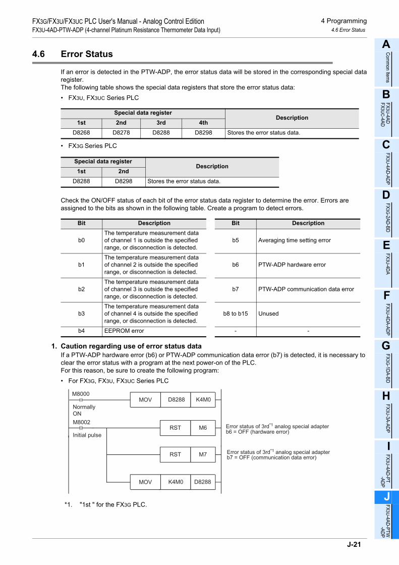
4 Programming4.6 Error Status
FX3G/FX3U/FX3UC PLC User's Manual - Analog Control EditionFX3U-4AD-PTW-ADP (4-channel Platinum Resistance Thermometer Data Input)
A
Comm
on Items
B
FX3U-4ADFX3UC-4AD
C
FX3U-4AD-ADP
D
FX3G-2AD-BD
E
FX3U-4DA
F
FX3U-4DA-ADP
G
FX3G-1DA-BD
H
FX3U-3A-ADP
I
FX3U-4AD-PT -ADP
J
FX3U-4AD-PTW -ADP
4.6 Error Status
If an error is detected in the PTW-ADP, the error status data will be stored in the corresponding special dataregister.The following table shows the special data registers that store the error status data:• FX3U, FX3UC Series PLC
• FX3G Series PLC
Check the ON/OFF status of each bit of the error status data register to determine the error. Errors are assigned to the bits as shown in the following table. Create a program to detect errors.
1. Caution regarding use of error status dataIf a PTW-ADP hardware error (b6) or PTW-ADP communication data error (b7) is detected, it is necessary to clear the error status with a program at the next power-on of the PLC.For this reason, be sure to create the following program:• For FX3G, FX3U, FX3UC Series PLC
*1. "1st " for the FX3G PLC.
Special data registerDescription
1st 2nd 3rd 4thD8268 D8278 D8288 D8298 Stores the error status data.
Special data registerDescription
1st 2ndD8288 D8298 Stores the error status data.
Bit Description Bit Description
b0The temperature measurement data of channel 1 is outside the specified range, or disconnection is detected.
b5 Averaging time setting error
b1The temperature measurement data of channel 2 is outside the specified range, or disconnection is detected.
b6 PTW-ADP hardware error
b2The temperature measurement data of channel 3 is outside the specified range, or disconnection is detected.
b7 PTW-ADP communication data error
b3The temperature measurement data of channel 4 is outside the specified range, or disconnection is detected.
b8 to b15 Unused
b4 EEPROM error - -
Error status of 3rd*1 analog special adapterb6 = OFF (hardware error)
Error status of 3rd*1 analog special adapterb7 = OFF (communication data error)
M8002
Initial pulse
Normally
ON
RST M6
RST M7
M8000MOV D8288 K4M0
MOV K4M0 D8288
J-21

4 Programming4.6 Error Status
FX3G/FX3U/FX3UC PLC User's Manual - Analog Control EditionFX3U-4AD-PTW-ADP (4-channel Platinum Resistance Thermometer Data Input)
• For FX3U, FX3UC Series PLC
2. Program Example 1 (For FX3G, FX3U, FX3UC Series PLC)
*1. "1st " for the FX3G PLC.
Error status of 1st analog special adapterb6 = OFF (hardware error)
Error status of 1st analog special adapterb7 = OFF (communication data error)
M8002
Initial pulseRST D8268.6
RST D8268.7
Y000M0
M1
M2
M3
M4
M5
M6
M7
Y001
Y002
Y003
Y004 EEPROM error in 3rd*1 adapter
Y005
Y006
Y007
Averaging time setting error in 3rd*1
adapter
PTW-ADP hardware error in 3rd*1
adapter
PTW-ADP communication data errorin 3rd*1 adapter
The temperature measurement data
of channel 1 is outside the specified
range, or disconnection is detected.
The temperature measurement data
of channel 2 is outside the specified
range, or disconnection is detected.
The temperature measurement data
of channel 3 is outside the specified
range, or disconnection is detected.
The temperature measurement data
of channel 4 is outside the specified
range, or disconnection is detected.
M8000MOV D8288 K4M0
J-22

4 Programming4.6 Error Status
FX3G/FX3U/FX3UC PLC User's Manual - Analog Control EditionFX3U-4AD-PTW-ADP (4-channel Platinum Resistance Thermometer Data Input)
A
Comm
on Items
B
FX3U-4ADFX3UC-4AD
C
FX3U-4AD-ADP
D
FX3G-2AD-BD
E
FX3U-4DA
F
FX3U-4DA-ADP
G
FX3G-1DA-BD
H
FX3U-3A-ADP
I
FX3U-4AD-PT -ADP
J
FX3U-4AD-PTW -ADP
3. Program Example 2 (For FX3U, FX3UC Series PLC)
Y000D8268.0
Y001D8268.1
Y002D8268.2
Y003D8268.3
Y004D8268.4
EEPROM error in 1st adapter
Y005D8268.5
Y006D8268.6
Y007D8268.7
Averaging time setting error in 1stadapter
PTW-ADP hardware error in 1stadapter
PTW-ADP communication data errorin 1st adapter
The temperature measurement dataof channel 1 is outside the specifiedrange, or disconnection is detected.
The temperature measurement dataof channel 2 is outside the specifiedrange, or disconnection is detected.
The temperature measurement dataof channel 3 is outside the specifiedrange, or disconnection is detected.
The temperature measurement dataof channel 4 is outside the specifiedrange, or disconnection is detected.
J-23

4 Programming4.7 Model Code
FX3G/FX3U/FX3UC PLC User's Manual - Analog Control EditionFX3U-4AD-PTW-ADP (4-channel Platinum Resistance Thermometer Data Input)
4.7 Model Code
Initial value: K21Numeric data type: Decimal (K)
When the PTW-ADP is connected, model code "21" will be stored in the corresponding special data register.The following table shows the special data registers that store the model code:• FX3U, FX3UC Series PLC
• FX3G Series PLC
Use the special data registers above to check whether PTW-ADP is connected or not.
1. Program Example (For FX3U, FX3UC Series PLC)
Special data registerDescription
1st 2nd 3rd 4thD8269 D8279 D8289 D8299 Model code
Special data registerDescription
1st 2ndD8289 D8299 Model code
FNC224LD =
D8269 K21 Checks the model code of the 1stanalog special adapter.Y010
J-24

4 Programming4.8 Basic Program Example
FX3G/FX3U/FX3UC PLC User's Manual - Analog Control EditionFX3U-4AD-PTW-ADP (4-channel Platinum Resistance Thermometer Data Input)
A
Comm
on Items
B
FX3U-4ADFX3UC-4AD
C
FX3U-4AD-ADP
D
FX3G-2AD-BD
E
FX3U-4DA
F
FX3U-4DA-ADP
G
FX3G-1DA-BD
H
FX3U-3A-ADP
I
FX3U-4AD-PT -ADP
J
FX3U-4AD-PTW -ADP
4.8 Basic Program Example
Create the following basic program example to read out the temperature measurement data.• For FX3G, FX3U, FX3UC Series PLCThe following program will store the temperature measurement data (°C) from channels 1 and 2 of the 3rd*1 adapter to D100 and D101, respectively. The averaging time is set to "1" (immediate data) for channel 1, and "5" for channel 2.
Even if the temperature measurement data is not stored in D100 or D101, data register D8280 or D8281 canbe directly used in the arithmetic operation instruction or a PID instruction.
*1. "1st " for the FX3G PLC.• For FX3U, FX3UC Series PLCThe following program will store the temperature measurement data (°C) from channels 1 and 2 of the 1stadapter to D100 and D101, respectively. The averaging time is set to "1" (immediate data) for channel 1, and"5" for channel 2.
Even if the temperature measurement data is not stored in D100 or D101, data register D8260 or D8261 canbe directly used in the arithmetic operation instruction or a PID instruction.
M8002
Initial
pulse
M8001
M8000
Normally
ON
M8280Sets the temperature unit to centigrade(°C).
M8002FNC 12
MOVK1 D8284
FNC 12MOV
K5 D8285
Sets the averaging time to "1" forchannel-1 data.
Sets the averaging time to "5" forchannel-2 data.
RST M6
RST M7
Error status of 3rd*1 analog specialadapterb6 = OFF (hardware error)
Error status of 3rd*1 analog specialadapterb7 = OFF (communication data error)
M8000FNC 12
MOVD8280 D100
FNC 12MOV
D8281 D101
Stores the current value of the channel-1temperature measurement data in the D100.
Stores the average value of the channel-2temperature measurement data in the D101.
MOV D8288 K4M0
MOV K4M0 D8288
M8002
M8001M8260 Sets the temperature unit to centigrade
(°C).
M8002FNC 12
MOVK1 D8264
FNC 12MOV
K5 D8265
Sets the averaging time to "1" forchannel-1 data.
Sets the averaging time to "5" forchannel-2 data.
RST D8268.6
RST D8268.7
Error status of 1st analog specialadapterb6 = OFF (hardware error)
Error status of 1st analog specialadapterb7 = OFF (communication data error)
M8000FNC 12
MOVD8260 D100
FNC 12MOV
D8261 D101
Stores the current value of the channel-1temperature measurement data in the D100.
Stores the average value of the channel-2temperature measurement data in the D101.
J-25

5 Troubleshooting5.1 PLC Version Number Check
FX3G/FX3U/FX3UC PLC User's Manual - Analog Control EditionFX3U-4AD-PTW-ADP (4-channel Platinum Resistance Thermometer Data Input)
5. Troubleshooting
This chapter describes the troubleshooting methods and error status.If the temperature measurement data is not input, or if the proper digital value is not input, check the followingitems:• Version number of the PLC• Wiring• Special devices• Programs• Error status
5.1 PLC Version Number Check
• Any versions (from Ver.2.20 (initial version) to the latest version) of the FX3U Series are compatible.• Check the version number of the FX3UC Series. The version number should be 1.30 or later.• Any versions (from Ver.1.00 (initial version) to the latest version) of the FX3G Series are compatible.
→ For a detailed description of the version number check method, refer to Section 1.3.
5.2 Wiring Check
Check the following items for wiring:
1. PowerThe PTW-ADP needs driving power. Verify that the power supply line is properly connected. Also check that the POWER indicator lamp of the PTW-ADP is on.
2. Platinum resistance thermometer sensor cableSeparate the cable of the platinum resistance thermometer from other power cables or inductive cables.
→ For a detailed description of wiring, refer to Chapter 3.
5.3 Special Device Check
Check whether the special devices for the PTW-ADP are correctly used:
1. Temperature measurementVerify that the special device for the selected channel is correctly selected. This special device should beselected depending on the connecting position and the channel.
2. Averaging timeCheck that the set averaging time is within the specified range. The averaging time should be set in the rangefrom 1 to 4095. If the set averaging time is outside the specified range, an error occurs.
3. Error statusCheck that no error is detected in the PTW-ADP.If an error is detected, check the details of the error, and then check the wiring and programs.
→ For a detailed description of special devices, refer to Chapter 4.
J-26

5 Troubleshooting5.4 Program Check
FX3G/FX3U/FX3UC PLC User's Manual - Analog Control EditionFX3U-4AD-PTW-ADP (4-channel Platinum Resistance Thermometer Data Input)
A
Comm
on Items
B
FX3U-4ADFX3UC-4AD
C
FX3U-4AD-ADP
D
FX3G-2AD-BD
E
FX3U-4DA
F
FX3U-4DA-ADP
G
FX3G-1DA-BD
H
FX3U-3A-ADP
I
FX3U-4AD-PT -ADP
J
FX3U-4AD-PTW -ADP
5.4 Program Check
Check the following items for the program:
1. Cancellation of error status at power-onWhen the power is turned off and then on again, the error status should be cleared (b6 and b7 should turn off)using the program.
2. Check of storage devicesVerify that different values are not being stored in the same device by the other parts of the programs.
5.5 Error Status Check
If an error occurs in the PTW-ADP, the corresponding bit will turn on.The bit which is turned ON due to the error status is held ON until overwritten to OFF by the program or thepower is cycled. If b6 or b7 is turned ON, then it is necessary to clear the error status using the program thenext time the power of the PLC is cycled.
To solve a problem, refer to the troubleshooting method described below:
1. Temperature measurement out of specified range or disconnection of line (b0 to b3)1) Description of error
The input temperature measurement value is outside the specified range.The temperature measurement value is not in the range between -115°C to 615°C.Or the line between PTW-ADP and the platinum resistance thermometer sensor is disconnected.
2) RemedyCheck that the input temperature measurement value is within the specified range. Also check the wiringcondition.
2. EEPROM error (b4)1) Description of error
The adjustment data set in the EEPROM before delivery from our factory cannot be read out properly oris destroyed.
2) RemedyPlease contact the nearest Mitsubishi Electric distributor office.
3. Averaging time setting error (b5)1) Description of error
The averaging time set for one of the channels (channels 1 to 4) is outside the specified range: 1 to 4095.
2) RemedyCheck that the averaging time is correctly set for each channel.
Bit Description Bit Description
b0The temperature measurement data of channel 1 is outside the specified range, or disconnection is detected.
b5 Averaging time setting error
b1The temperature measurement data of channel 2 is outside the specified range, or disconnection is detected.
b6 PTW-ADP hardware error
b2The temperature measurement data of channel 3 is outside the specified range, or disconnection is detected.
b7 PTW-ADP communication data error
b3The temperature measurement data of channel 4 is outside the specified range, or disconnection is detected.
b8 to 15 Unused
b4 EEPROM error - -
J-27

5 Troubleshooting5.5 Error Status Check
FX3G/FX3U/FX3UC PLC User's Manual - Analog Control EditionFX3U-4AD-PTW-ADP (4-channel Platinum Resistance Thermometer Data Input)
4. PTW-ADP hardware error (b6)1) Description of error
The PTW-ADP does not operate properly.2) Remedy
Check that the 24V DC power is properly supplied to the PTW-ADP. Also check that the PTW-ADP is correctly connected to the PLC.If the problem cannot be solved even after the above check, please contact the nearest Mitsubishi Electric distributor office.
5. PTW-ADP communication data error (b7)1) Description of error
A communication error is detected between the PTW-ADP and the PLC.2) Remedy
Check that the PTW-ADP is correctly connected to the PLC.If the problem cannot be solved even after the above check, please contact the nearest Mitsubishi Electric distributor office.
J-28

K
FX3U-4AD-PNK -ADP
L
FX3U-4AD-TC -ADP
M
PID Instruction (FNC 88)
FX3G/FX3U/FX3UC PLC User's Manual - Analog Control EditionFX3U-4AD-PNK-ADP (4-channel Resistance Thermometer Data Input)
FX3G/FX3U/FX3UC Series Programmable Controllers
User's Manual [Analog Control Edition] FX3U-4AD-PNK-ADP (4-channel Resistance Thermometer Data Input)
Foreword
This manual describes the specifications, wiring, and operation methods for the FX3U-4AD-PNK-ADP special adapter (4-channel resistance thermometer data input) and should be read and understood before attempting to install or use the unit.Store this manual in a safe place so that you can take it out and read it whenever necessary. Always forward it to the end user.
© 2005 MITSUBISHI ELECTRIC CORPORATION
This manual confers no industrial property rights or any rights of any other kind, nor does it confer any patentlicenses. Mitsubishi Electric Corporation cannot be held responsible for any problems involving industrial propertyrights which may occur as a result of using the contents noted in this manual.
K-1

FX3G/FX3U/FX3UC PLC User's Manual - Analog Control EditionFX3U-4AD-TC-ADP (4-channel Resistance Thermocouple Data Input)
K-2

1 Outline1.1 Outline of Functions
FX3G/FX3U/FX3UC PLC User's Manual - Analog Control EditionFX3U-4AD-PNK-ADP (4-channel Resistance Thermometer Data Input)
K
FX3U-4AD-PNK -ADP
L
FX3U-4AD-TC -ADP
M
PID Instruction (FNC 88)
1. Outline
This chapter describes the outline of FX3U-4AD-PNK-ADP (referred to as PNK-ADP).
1.1 Outline of Functions
The FX3U-4AD-PNK-ADP is an analog special adapter. Connect the FX3U-4AD-PNK-ADP to the FX3G/FX3U/FX3UC Series PLC to read the data from the 4-channel resistance thermometer.1) Up to 4 PNK-ADP units can be connected to the FX3U/FX3UC Series PLC.
Up to 2*1 PNK-ADP units can be connected to the FX3G Series PLC.(Including other analog special adapters)
2) Thermometer types Pt1000 and Ni1000 can be connected. (However, it's impossible to use both typesPt1000 and Ni1000 with 1 adapter.)
3) The temperature data will be automatically written to the special data register of the FX3G/FX3U/FX3UCSeries PLC.
Number of connectable
units
……For a detaileddescription of wiring,refer to Chapter 3.
……To check the connectablePLC model number, referto Section 1.3.
Point and section to be referred toSystem
……
Special devices ……For a detailed descriptionof special devices, refer toChapter 4.
For a detailed descriptionof a basic program, refer toSection 4.9.
Analog data
Refer to the system configuration shown in the User's Manual - Hardware Edition to check the number of connectable unitsand to configure the entire system.
*2. The expansion board is not required when connecting with the FX
For the FX3G Series PLC a connector conversion adapter is used.
3UC (D, DSS) PLC.
FX3U, FX3UC Series PLC : 4 maximum
FX3G Series PLC : 2*1 maximum(including other analog special adapters)
1st adapter M/D8260 to M/D8269
M/D8270 to M/D8279
M/D8280 to M/D8289
M/D8290 to M/D8299
2nd adapter
3rd adapter
4th adapter
++
Expansionboard*2
FX3U/FX3UC/FX3G Series PLC
For FX3U, FX3UC
Series PLC
4thadapter
3rdadapter
2ndadapter
1stadapter
Transfer direction
*1. Only 1 analog special adapter can be connected to the 14-point and 24-point type main unit.
Description
Resistance thermometer sensor type
Pt1000 and Ni1000
Temperature measurement
Setting of temperature unitSwitching of types between
type Pt1000 and Ni1000
Setting of averaging time
K-3

1 Outline1.2 Setup Procedure Before Starting Operation
FX3G/FX3U/FX3UC PLC User's Manual - Analog Control EditionFX3U-4AD-PNK-ADP (4-channel Resistance Thermometer Data Input)
1.2 Setup Procedure Before Starting Operation
Before starting analog input using PNK-ADP, follow the procedure below to set up the system:
Specifications:
•Operation environment
•Performance specifications
•Input characteristics
Specifications check
Refer to Chapter 2.
System configuration and selection
Wiring
Refer to Chapter 3.
FX3U-4AD-PNK-ADP
System configuration:
(Refer to the common pages for analog control.)
•Selection of units
Refer to the common
pages.
Wiring:
•Selection of sensor cable
•Power supply line
•Analog input line
Outline of system:
•Compatible PLC version number
•Compatible programming tool version number
Outline
Refer to Chapter 1.
Programming
Refer to Chapter 4.
Programming:
•Details of special devices
•Examples of basic programs
If the error status data or the input analog value is
abnormal, refer to Chapter 5 "Troubleshooting."
K-4

1 Outline1.3 Connectable PLC and Its Version Number
FX3G/FX3U/FX3UC PLC User's Manual - Analog Control EditionFX3U-4AD-PNK-ADP (4-channel Resistance Thermometer Data Input)
K
FX3U-4AD-PNK -ADP
L
FX3U-4AD-TC -ADP
M
PID Instruction (FNC 88)
1.3 Connectable PLC and Its Version Number
PNK-ADP is compatible with the following PLC.
1. Version checkSpecial data register D8001 contains information for determining the PLC version number.
→ For a detailed description of the version check, refer to A. Common Items Subsection 5.1.2.
2. How to check the manufacturer's serial numberThe year and month of production of the product can be checked on the nameplate, and on the front of the product.
→ For a detailed description of how to check the manufacturer's serial number,refer to A. Common Items Subsection 5.1.1.
1.4 Compatible Programming Tool Version Number
Use the programming tool having the following version number to create programs for PNK-ADP:
1. GX Works2
2. GX Developer• FX3U/FX3UC Series PLC
• FX3G Series PLC
If a programming tool with the wrong version number is used, programming will not be possible.*1. For Ver. 8.13P to 8.24A of GX Developer, select FX3UC for the PLC type.
3. FX-30P
Compatible PLC Version number Date of productionFX3U Series PLC Ver. 2.20 or later After May 2005 (initial production)
FX3UC Series PLC Ver. 1.30 or later After August 2004
FX3G Series PLC Ver. 1.00 or later After June 2008 (initial production)
Software Version number RemarksGX Works2SW DNC-GXW2-J Ver. 1.07H or later -
GX Works2SW DNC-GXW2-E Ver. 1.08J or later -
Software Version number RemarksGX DeveloperSW D5C-GPPW-J Ver. 8.13P or later
When selecting the model, select FX3U(C)*1.GX DeveloperSW D5C-GPPW-E Ver. 8.18U or later
Software Version number RemarksGX Developer• SW D5C-GPPW-J• SW D5C-GPPW-E
Ver. 8.72A or later -
Model name Version number RemarksFX-30P Ver. 1.00 or later -
K-5

2 Specifications2.1 Generic Specifications
FX3G/FX3U/FX3UC PLC User's Manual - Analog Control EditionFX3U-4AD-PNK-ADP (4-channel Resistance Thermometer Data Input)
2. Specifications
This chapter describes the general, power supply, and performance specifications for the PNK-ADP.
2.1 Generic Specifications
*1. The criterion is shown in IEC61131-2.*2. If PNK-ADP is connected to the FX3UC Series PLC, direct installation is not possible.*3.
→ For a detailed description of the grounding, refer to Section 3.7.*4. If the pressure is higher than the atmospheric pressure, do not use the PNK-ADP.
The PNK-ADP may malfunction.
2.2 Power Supply Specifications
Item Specifications
Ambient temperature 0 to 55°C (32 to 131°F) when operating -25 to 75°C (-13 to 167°F) when stored
Relative humidity 5 to 95%RH (no condensation) when operating
Vibrationresistance*1
Frequency(Hz)
Acceleration(m/s2)
Half amplitude(mm)
Tested 10 times in each direction (X-, Y-, and Z-axis directions) (Total: 80 min, each)
DIN Rail Mounting10 - 57 - 0.035
57 - 150 4.9 -
Direct Mounting*210 to 57 − 0.075
57 to 150 9.8 −
Shock resistance*1 147 m/s2 Acceleration, Action time: 11ms, 3 times by half-sine pulse in each direction X, Y,and Z
Noise resistance Using noise simulator of:Noise voltage: 1,000Vp-p / Noise width: 1µs / Rise: 1ns / Cycle: 30 to 100Hz
Dielectric withstand voltage 500 V AC, for 1 min
Between batch of all terminals and ground terminalInsulation resistance 5MΩ or more using 500V DC
insulation resistance meter
GroundingClass D grounding (grounding resistance: 100 Ω or less) <Common grounding with a heavy electrical system is not allowed.>*3
Workingenvironment Free from corrosive or flammable gas and excessive conductive dusts
Working altitude < 2000m*4
Item SpecificationsA/D conversion circuit driving power
24V DC +20% -15%, 45mA(It is necessary to connect a 24V DC power supply to the terminal block.)
Interface driving power5V DC, 15mA (Since the internal power is supplied from the FX Series main unit, it is notnecessary to supply the power.)
PLCOther
equipmentPLCOther
equipmentPLCOther
equipment
Shared groundingGood condition
Common groundingNot allowed
Independent groundingBest condition
K-6

2 Specifications2.3 Performance Specifications
FX3G/FX3U/FX3UC PLC User's Manual - Analog Control EditionFX3U-4AD-PNK-ADP (4-channel Resistance Thermometer Data Input)
K
FX3U-4AD-PNK -ADP
L
FX3U-4AD-TC -ADP
M
PID Instruction (FNC 88)
2.3 Performance Specifications
ItemSpecifications
Centigrade (°C) Fahrenheit (°F)
Input signal
Platinum resistance thermometer sensor (2-wire or 3-wire) Pt1000JIS C 1604-1997
Nickel resistance thermometer sensor (2-wire or 3-wire) Ni1000DIN 43760-1987
Rated temperature range
Pt1000 -50°C to +250°C Pt1000 -58°F to +482°F
Ni1000 -40°C to +110°C Ni1000 -40°F to +230°F
Digital outputPt1000 -500 to +2500 Pt1000 -580 to +4820
Ni1000 -400 to +1100 Ni1000 -400 to +2300
ResolutionPt1000
0.1°CPt1000
0.2°FNi1000 Ni1000
Total accuracy ±0.5% for full scale (when ambient temperature is 25°C±5°C)±1.0% for full scale (when ambient temperature is in the range of 0 to 55°C)
A/D conversion time
• FX3U/FX3UC Series PLC : 200µs (The data will be updated at every scan time.)• FX3G PLC : 250µs (The data will be updated at every scan time.)
→For a detailed description of data update, refer to Section2.4.
Input characteristics
Insulation method• The photocoupler is used to insulate the analog input area from the PLC.• The DC/DC converter is used to insulate the power supply line from the analog input area.• Channels are not insulated from each other.
Number of I/O points occupied
0 points(This number is not related to the maximum number of input/output points of the PLC.)
0
+250°C
+2500
-50°C
-500
Appro
x.
-55
°C
Appro
x.
+256
°C
+2560
-550
-Pt1000
0
+110°C
+1100
-40°C
-400
Appro
x.
-45
°C
Appro
x.
+115
°C
+1150
-450
-Ni1000
0
+4820
-580
+4920
-670
-Pt1000
Appro
x.
+492.8
°F
+482
-58
Appro
x.
-67
°F
°F
°F
0
+2300
-400
+2390
-490
-Ni1000A
ppro
x.
+239
°F
+230°F
-40°F
Appro
x.
-49
°F
K-7
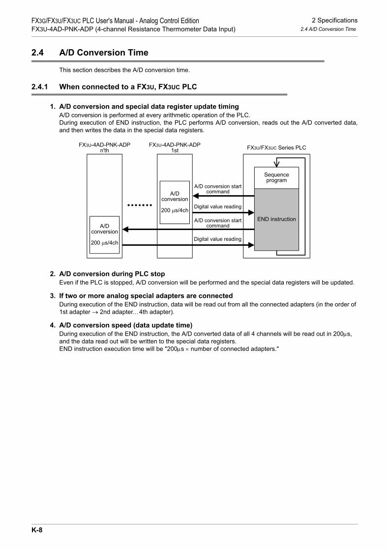
2 Specifications2.4 A/D Conversion Time
FX3G/FX3U/FX3UC PLC User's Manual - Analog Control EditionFX3U-4AD-PNK-ADP (4-channel Resistance Thermometer Data Input)
2.4 A/D Conversion Time
This section describes the A/D conversion time.
2.4.1 When connected to a FX3U, FX3UC PLC
1. A/D conversion and special data register update timingA/D conversion is performed at every arithmetic operation of the PLC.During execution of END instruction, the PLC performs A/D conversion, reads out the A/D converted data,and then writes the data in the special data registers.
2. A/D conversion during PLC stopEven if the PLC is stopped, A/D conversion will be performed and the special data registers will be updated.
3. If two or more analog special adapters are connectedDuring execution of the END instruction, data will be read out from all the connected adapters (in the order of 1st adapter → 2nd adapter…4th adapter).
4. A/D conversion speed (data update time)During execution of the END instruction, the A/D converted data of all 4 channels will be read out in 200µs, and the data read out will be written to the special data registers.END instruction execution time will be "200µs × number of connected adapters."
FX3U/FX3UC Series PLCFX3U-4AD-PNK-ADP
1stFX3U-4AD-PNK-ADP
n'th
A/Dconversion
200 µs/4ch
A/Dconversion
200 µs/4ch
Digital value reading
A/D conversion startcommand
END instruction
Sequenceprogram
Digital value reading
A/D conversion startcommand
K-8

2 Specifications2.5 Temperature Measurement
FX3G/FX3U/FX3UC PLC User's Manual - Analog Control EditionFX3U-4AD-PNK-ADP (4-channel Resistance Thermometer Data Input)
K
FX3U-4AD-PNK -ADP
L
FX3U-4AD-TC -ADP
M
PID Instruction (FNC 88)
2.4.2 When connected to a FX3G PLC
1. A/D conversion and special data register update timingA/D conversion is performed at every scan time of the PLC.During execution of END instruction, the PLC performs A/D conversion, reads out the A/D converted data,and then writes the data in the special data registers.
2. A/D conversion during PLC stopEven if the PLC is stopped, A/D conversion will be performed and the special data registers will be updated.
3. If two analog special adapters are connectedDuring execution of the END instruction, data will be read out from all the connected adapters (in the order of 1st adapter → 2nd adapter).
4. A/D conversion speed (data update time)During execution of the END instruction, the A/D converted data of all 4 channels will be read out in 250µs, and the data read out will be written to the special data registers.END instruction execution time will be "250µs × number of connected adapters."
2.5 Temperature Measurement
To stabilize the temperature measurement, warm-up the system for 30 minutes or more after power-on.
FX3G Series PLCFX3U-4AD-PNK-ADP
1stFX3U-4AD-PNK-ADP
2nd
A/Dconversion
250 µs/4ch
A/Dconversion
250 µs/4ch
Digital value reading
A/D conversion startcommand
END instruction
Sequenceprogram
Digital value reading
A/D conversion startcommand
K-9

3 WiringFX3G/FX3U/FX3UC PLC User's Manual - Analog Control EditionFX3U-4AD-PNK-ADP (4-channel Thermometer Data Input)
3. Wiring
This chapter describes the PNK-ADP wiring.Observe the following caution to wire the PNK-ADP.
WIRING PRECAUTIONS
• Make sure to cut off all phases of the power supply externally before attempting wiring work.Failure to do so may cause electric shock or damages to the product.
WIRING PRECAUTIONS
• Connect the DC power supply wiring to the dedicated terminals described in this manual.If an AC power supply is connected to a DC input/output terminal or DC power supply terminal, the PLC will beburnt out.
• Do not wire vacant terminals externally.Doing so may damage the product.
• Perform class D grounding (grounding resistance: 100Ω or less) to the grounding terminal on the main unit.Do not use common grounding with heavy electrical systems.
• When drilling screw holes or wiring, make sure cutting or wire debris does not enter the ventilation slits.Failure to do so may cause fire, equipment failures or malfunctions.
• Make sure to observe the following precautions in order to prevent malfunctions under the influence of noise:- Do not bundle the power line or twisted shielded cable together with or lay it close to the main circuit, high-
voltage line, or load line.Otherwise, noise disturbance and/or surge induction are likely to take place. As a guideline, lay the control line at least 100mm (3.94") or more away from the main circuit, high-voltage line, or load line.
- Ground the shield of the analog input/output cable at one point on the signal receiving side. However, do not use common grounding with heavy electrical systems.
• Make sure to properly wire to the European terminal board in accordance with the following precautions.Failure to do so may cause electric shock, equipment failures, a short-circuit, wire breakage, malfunctions, ordamage to the product.- The disposal size of the cable end should follow the dimensions described in the manual.- Tightening torque should follow the specifications in the manual.- Twist the end of strand wire and make sure there are no loose wires. - Do not solder-plate the electric wire ends.- Do not connect more than the specified number of wires or electric wires of unspecified size.- Affix the electric wires so that neither the terminal block nor the connected parts are directly stressed.
K-10

3 Wiring3.1 Terminal Layout
FX3G/FX3U/FX3UC PLC User's Manual - Analog Control EditionFX3U-4AD-PNK-ADP (4-channel Resistance Thermometer Data Input)
K
FX3U-4AD-PNK -ADP
L
FX3U-4AD-TC -ADP
M
PID Instruction (FNC 88)
3.1 Terminal Layout
The terminals of the PNK-ADP are arranged as follows:
Signal Application
External power
Channel-1 Pt1000/Ni1000
Channel-2 Pt1000/Ni1000
Channel-3 Pt1000/Ni1000
Channel-4 Pt1000/Ni1000
sensor input
sensor input
sensor input
sensor input
24+
24-
L2+
L1+
L2-
L3-
L4+
L1-
l1-
l2-
l3-
l4-
L3+
L4-
Ground terminal
24+
24-
L1+
L1-
L2+
L2-
L3+
L3-
L4+
I4-
I2-
I3-
I1-
FX3U-4AD-PNK
-ADP
POWER
L4-
K-11

3 Wiring3.2 Applicable Cables and Terminal Tightening Torque
FX3G/FX3U/FX3UC PLC User's Manual - Analog Control EditionFX3U-4AD-PNK-ADP (4-channel Resistance Thermometer Data Input)
3.2 Applicable Cables and Terminal Tightening Torque
Use the following cables to connect with the counterpart equipment. Terminate the cable end as shown below.
1. CablesApplicable cable and tightening torque
*1. Old model name : CRIMPFOX ZA 3*2. Old model name : CRIMPFOX UD 6
2. Termination of cable endTo terminate the cable, treat the stranded/single wire directly or use a rod terminal with insulation sleeve.• To directly terminate the end of a stranded/single-wire cable:
- Twist the end of the stranded cable so that the "barbed wires" cannot protrude.
- Do not solder-plate the end of the cable.
• To terminate cable end using a rod terminal with insulation sleeve:If the cable cover is too thick, it may be difficult to insert the cable intothe insulation sleeve. For this reason, select an appropriate cable whilereferring to the external view.<Reference>
*3. Old model name : CRIMPFOX ZA 3*4. Old model name : CRIMPFOX UD 6
3. Tool• To tighten terminals, use a small-sized screwdriver whose head is straight and is not widened as shown in
the figure to the right.
Note:If the diameter of screwdriver grip is too small, tightening torque will notbe able to be achieved. To achieve the appropriate tightening torqueshown in the table above, use the following screwdriver or anappropriate replacement (grip diameter: approximately 25mm (0.98")).<Reference>
Wire size (stranded/single-wire)
Tightening torque Termination
Single-wire 0.3 mm2 to 0.5 mm2 (AWG22 to 20)
0.22 N•m to 0.25 N•m
• To connect a stranded cable, peel the cover off the cableand then twist the core before connection.
• To connect a single-wire cable, just strip the cover off thecable before connection.2-wire 0.3mm2(AWG22)
Rod terminalwithinsulation sleeve
0.3 mm2 to 0.5 mm2 (AWG22-20)(Refer to the rod terminal external view shown in the following figure.)
• Rod terminal with insulation sleeve (recommended terminal)AI 0.5-8WH : Manufactured by Phoenix Contact
• Caulking toolCRIMPFOX 6*1 : Manufactured by Phoenix Contact(or CRIMPFOX 6T-F*2 : Manufactured by Phoenix Contact)
Manufacturer Model Caulking tool
Phoenix Contact AI 0.5-8WH CRIMPFOX 6*3
(or CRIMPFOX 6T-F*4)
Manufacturer ModelPhoenix Contact SZS 0.4×2.5
9mm
Termination of cable end
(0.35")
8mm (0.31")
Contact area(Crimp area)
14mm2.6mm(0.1")
Insulation sleeve
(0.55")
0.4mm 2.5mm
The headshould bestraight.
(0.01") (0.09")
K-12

3 Wiring3.3 Power Supply Line
FX3G/FX3U/FX3UC PLC User's Manual - Analog Control EditionFX3U-4AD-PNK-ADP (4-channel Resistance Thermometer Data Input)
K
FX3U-4AD-PNK -ADP
L
FX3U-4AD-TC -ADP
M
PID Instruction (FNC 88)
3.3 Power Supply Line
Connect the 24V DC power supply line of the PNK-ADP to the 24+ and 24- terminals of the terminal block.
3.3.1 To connect to the FX3G, FX3U Series PLC
Caution regarding connection of the power supply line:
• Ground the " " terminal to a class-D grounding power supply line (100Ω or less) together with the grounding terminal of the PLC main unit.
• When using an external power supply, turn it ON at the same time with the main unit or earlier than the main unit. When turning OFF the power, confirm the safety of the system, and then turn OFF the power of the PLC (including special adapter) at the same time.
3.3.2 To connect to the FX3UC Series PLC
Cautions regarding connection of the power supply line:• For the 24V DC power supply line, be sure to use the same power as the FX3UC Series PLC.
• Ground the " " terminal to a class-D grounding power supply line (100Ω or less) together with the ground terminal of the PLC main unit.
24V DCClass-D
grounding
Terminalblock
PNK-ADPFX3G/FX3U
Series PLC
(Main unit)
+5V
24+24-
1. To use an external power
Class-Dgrounding
Terminalblock
PNK-ADPFX3G/FX3U
Series PLC
(Main unit)
+5V
24+24- 24V0V
2. To use the 24V DC power of the PLC
24V DCClass-D
grounding
Terminalblock
PNK-ADP
GreenRedBlack
FX3UC Series PLC(Main unit)
Powerconnector
24+24- 24+24- 24+24-
Powerconnector
Powercrossoverconnector
RedBlack
FX2NC
Series PLC(Input extension
block)
+5V
24+24-
K-13

3 Wiring3.4 Selection of the Resistance Thermometer Sensor
FX3G/FX3U/FX3UC PLC User's Manual - Analog Control EditionFX3U-4AD-PNK-ADP (4-channel Resistance Thermometer Data Input)
3.4 Selection of the Resistance Thermometer Sensor
Select the Pt1000/Ni1000 (2-wire or 3-wire sensors) resistance thermometer sensor.
3.5 Wiring of the Resistance Thermomester Sensor
Wiring depends on the resistance thermometer sensor type selected. Refer to the following wiring diagrams:
*1. 24V DC service power supply of the FX3G/FX3U Series PLC can also be used.*2. When using a 2-wire temperature sensor type, short-circuit the [L -] terminal and the [I -] terminal.
For the lead wire use a 10Ω resistance or less per line.*3. Separate the cable of the platinum resistance themometer sensor from the other power cables or
areas easily affected by inductive noise (of the commercial power, etc.).
1MΩ
ch
PNK-ADP
Class-D grounding
+5V
24+
24-
Shield wireTerminal
block
24V DC*1
L+, L-, I-, ch: represents the channel number.
3-wiresensorstype
1MΩ
47kΩ47kΩ
+5V
1MΩ
ch
+5V
1MΩ
47kΩ47kΩ2-wiresensorstype
L-
I-
L+
L-
I-
L+
*2
*3
Resistance thermometerwiring
External power supplywiring
K-14

3 Wiring3.6 Caution Regarding Wiring
FX3G/FX3U/FX3UC PLC User's Manual - Analog Control EditionFX3U-4AD-PNK-ADP (4-channel Resistance Thermometer Data Input)
K
FX3U-4AD-PNK -ADP
L
FX3U-4AD-TC -ADP
M
PID Instruction (FNC 88)
3.6 Caution Regarding Wiring
• It is not possible to connect different types of resistance thermometer to 4 channels of PNK-ADP. Be sure to use the same type of resistance thermometer for all the channels.
3.7 Grounding
Grounding should be performed as stated below.• The grounding resistance should be 100Ω or less.• Independent grounding should be performed for best results.
When independent grounding is not performed, perform "shared grounding" as shown in the following figure.
→ For details, refer to the User’s Manual - Hardware Edition of the PLC Series.
• The grounding wire size should be AWG22 to 20 (0.3 to 0.5 mm2).• The grounding point should be close to the PLC, and all grounding wires should be as short as possible.
PLCOther
equipmentPLCOther
equipmentPLCOther
equipment
Shared groundingGood condition
Common groundingNot allowed
Independent groundingBest condition
K-15

4 Programming4.1 Loading of A/D Conversion Data
FX3G/FX3U/FX3UC PLC User's Manual - Analog Control EditionFX3U-4AD-PNK-ADP (4-channel Resistance Thermometer Data Input)
4. Programming
This chapter describes how to create programs that can read out the analog data using the PNK-ADP.
4.1 Loading of A/D Conversion Data
1) The input analog data will be converted into digital data and then stored in the special devices of the FX3U/FX3UC/FX3G Series PLC.
2) If data is stored in the special devices, the averaging time can be set, and the input mode can be specified.
3) Special auxiliary relays (10 points) and special data registers (10 points) are assigned automatically starting from the adapter nearest to the main unit.
→ For a detailed description of special device assignment, refer to Subsection 4.2.• FX3U, FX3UC Series PLC
The analog special adapter nearest to the main unit is counted as the 1st analog special adapter, and the next adapter as the 2nd analog special adapter, and so on. However, in this case, do not include the high-speed input/output special adapter, communication special adapter, and the CF card special adapter.
Sequenceprogram
Special devices
A/D
A/D
A/D
A/D
Communi-cationspecialadapter
FX3U-4AD-PNK-ADP
FX3U-4AD-PNK-ADP
FX3U-4AD-PNK-ADP
FX3U-4AD-PNK-ADP FX3U/FX3UC Series PLC
1st2nd3rd4th
High-speedinput/output
specialadapter
Special auxiliary relays:M8280 to M8289
Special data registers:D8280 to D8289
Special auxiliary relays:M8270 to M8279
Special data registers:D8270 to D8279
Special auxiliary relays:M8260 to M8269
Special data registers:D8260 to D8269
Special auxiliary relays:M8290 to M8299
Special data registers:D8290 to D8299
K-16

4 Programming4.1 Loading of A/D Conversion Data
FX3G/FX3U/FX3UC PLC User's Manual - Analog Control EditionFX3U-4AD-PNK-ADP (4-channel Resistance Thermometer Data Input)
K
FX3U-4AD-PNK -ADP
L
FX3U-4AD-TC -ADP
M
PID Instruction (FNC 88)
• FX3G Series PLC
The analog special adapter nearest to the main unit is counted as the 1st analog special adapter, and the next adapter as the 2nd analog special adapter, and so on. However, in this case, do not include the connect conversion adapter and the communication special adapter.
*1. The second special adapter is not available in the FX3G Series PLC(14-point and 24-point type).
2nd*1 1st
Communi-
cation
special
adapter
Connector
conversion
adapter
FX3U-4AD
-PNK-ADP
FX3U-4AD
-PNK-ADP
Sequence
Program
FX3G Series PLC
Special devices
Special auxiliary relays:
M8280 to M8289
Special data registers:
D8280 to D8289
Special auxiliary relays:
M8290 to M8299
Special data registers:
D8290 to D8299
A/D
A/D
K-17

4 Programming4.2 List of Special Devices
FX3G/FX3U/FX3UC PLC User's Manual - Analog Control EditionFX3U-4AD-PNK-ADP (4-channel Resistance Thermometer Data Input)
4.2 List of Special Devices
If PNK-ADP is connected, special devices will be assigned automatically as shown in the following table:• FX3U, FX3UC Series PLC
R: Read / W: Write
Special device
Device numberDescription Attribute Refer to
1st 2nd 3rd 4th
Special auxiliaryrelay
M8260 M8270 M8280 M8290 Selects the temperature unit R/W Section 4.3
M8261 M8271 M8281 M8291 Input sensor selection R/W Section 4.4
M8262 to M8269
M8272 to M8279
M8282 to M8289
M8292 to M8299 Unused (Do not use.) - -
Specialdataregister
D8260 D8270 D8280 D8290 Channel-1 temperature measurement data R
Section 4.5
D8261 D8271 D8281 D8291 Channel-2 temperature measurement data R
D8262 D8272 D8282 D8292 Channel-3 temperature measurement data R
D8263 D8273 D8283 D8293 Channel-4 temperature measurement data R
D8264 D8274 D8284 D8294 Averaging time for channel 1 (Setting range: 1 to 4095) R/W
Section 4.6
D8265 D8275 D8285 D8295 Averaging time for channel 2 (Setting range: 1 to 4095) R/W
D8266 D8276 D8286 D8296 Averaging time for channel 3 (Setting range: 1 to 4095) R/W
D8267 D8277 D8287 D8297 Averaging time for channel 4 (Setting range: 1 to 4095) R/W
D8268 D8278 D8288 D8298 Error status R/W Section 4.7
D8269 D8279 D8289 D8299 Model code = 11 R Section 4.8
K-18
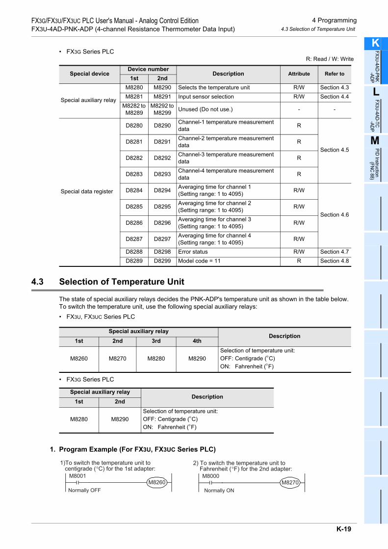
4 Programming4.3 Selection of Temperature Unit
FX3G/FX3U/FX3UC PLC User's Manual - Analog Control EditionFX3U-4AD-PNK-ADP (4-channel Resistance Thermometer Data Input)
K
FX3U-4AD-PNK -ADP
L
FX3U-4AD-TC -ADP
M
PID Instruction (FNC 88)
• FX3G Series PLCR: Read / W: Write
4.3 Selection of Temperature Unit
The state of special auxiliary relays decides the PNK-ADP's temperature unit as shown in the table below.To switch the temperature unit, use the following special auxiliary relays:• FX3U, FX3UC Series PLC
• FX3G Series PLC
1. Program Example (For FX3U, FX3UC Series PLC)
Special deviceDevice number
Description Attribute Refer to1st 2nd
Special auxiliary relay
M8280 M8290 Selects the temperature unit R/W Section 4.3M8281 M8291 Input sensor selection R/W Section 4.4
M8282 to M8289
M8292 to M8299 Unused (Do not use.) - -
Special data register
D8280 D8290 Channel-1 temperature measurement data R
Section 4.5D8281 D8291 Channel-2 temperature measurement
data R
D8282 D8292 Channel-3 temperature measurement data R
D8283 D8293 Channel-4 temperature measurement data R
D8284 D8294 Averaging time for channel 1 (Setting range: 1 to 4095) R/W
Section 4.6D8285 D8295 Averaging time for channel 2
(Setting range: 1 to 4095) R/W
D8286 D8296 Averaging time for channel 3 (Setting range: 1 to 4095) R/W
D8287 D8297 Averaging time for channel 4 (Setting range: 1 to 4095) R/W
D8288 D8298 Error status R/W Section 4.7D8289 D8299 Model code = 11 R Section 4.8
Special auxiliary relayDescription
1st 2nd 3rd 4th
M8260 M8270 M8280 M8290Selection of temperature unit:OFF: Centigrade (°C)ON: Fahrenheit (°F)
Special auxiliary relayDescription
1st 2nd
M8280 M8290Selection of temperature unit:OFF: Centigrade (°C)ON: Fahrenheit (°F)
1)To switch the temperature unit to centigrade (°C) for the 1st adapter:
M8001M8260
Normally OFF
2) To switch the temperature unit to Fahrenheit (°F) for the 2nd adapter:
M8000M8270
Normally ON
K-19

4 Programming4.4 Input sensor selection
FX3G/FX3U/FX3UC PLC User's Manual - Analog Control EditionFX3U-4AD-PNK-ADP (4-channel Resistance Thermometer Data Input)
4.4 Input sensor selection
Turn on the Pt1000 type or off the Ni1000 type selection special auxiliary relay to select the Pt1000 or Ni1000for PNK-ADP.The input sensor type will be selected for all the channels at the same time.To select the input sensor type, use the following special auxiliary relays:• FX3U, FX3UC Series PLC
• FX3G Series PLC
1. Program Example (For FX3U, FX3UC Series PLC)
Special auxiliary relayDescription
1st 2nd 3rd 4th
M8261 M8271 M8281 M8291Input sensor selection:OFF: Pt1000ON: Ni1000
Special auxiliary relayDescription
1st 2nd
M8281 M8291Input sensor selection:OFF: Pt1000ON: Ni1000
1) To select Pt1000 for the 1st adapter:
M8001M8261
Normally OFF
2)To select Ni1000 for the 2nd adapter :
M8000M8271
Normally ON
K-20

4 Programming4.5 Temperature Measurement
FX3G/FX3U/FX3UC PLC User's Manual - Analog Control EditionFX3U-4AD-PNK-ADP (4-channel Resistance Thermometer Data Input)
K
FX3U-4AD-PNK -ADP
L
FX3U-4AD-TC -ADP
M
PID Instruction (FNC 88)
4.5 Temperature Measurement
The temperature data input in the PNK-ADP will be stored in the special data registers.The special data registers that store the temperature data are shown in the following table:• FX3U, FX3UC Series PLC
• FX3G Series PLC
The immediate data or the average data (data averaged in accordance with the specified averaging time) will be stored in the above data registers as the temperature measurement data.
→ For a detailed description of the averaging time, refer to Section 4.6.
1. Caution regarding temperature measurementThe temperature measurement data are for reading only.Do not change (rewrite) the current data using the sequence program, indicator, or device monitor of the programming tool.
2. Program Example (For FX3U, FX3UC Series PLC)
Even if the temperature measurement data is not stored in D100 or D101, data registers D8260 or D8261 can be directly used in the arithmetic operation instruction or a PID instruction.
Special data registerDescription
1st 2nd 3rd 4thD8260 D8270 D8280 D8290 Stores the channel-1 temperature measurement data.
D8261 D8271 D8281 D8291 Stores the channel-2 temperature measurement data.
D8262 D8272 D8282 D8292 Stores the channel-3 temperature measurement data.
D8263 D8273 D8283 D8293 Stores the channel-4 temperature measurement data.
Special data registerDescription
1st 2ndD8280 D8290 Stores the channel-1 temperature measurement data.
D8281 D8291 Stores the channel-2 temperature measurement data.
D8282 D8292 Stores the channel-3 temperature measurement data.
D8283 D8293 Stores the channel-4 temperature measurement data.
M8000
NormallyON
FNC 12MOV
D8260 D100
FNC 12MOV
D8261 D101
Stores the channel-1 temperature measurement dataof the 1st analog special adapter in the D100.
Stores the channel-2 temperature measurement dataof the 1st analog special adapter in the D101.
K-21

4 Programming4.6 Averaging Time
FX3G/FX3U/FX3UC PLC User's Manual - Analog Control EditionFX3U-4AD-PNK-ADP (4-channel Resistance Thermometer Data Input)
4.6 Averaging Time
Setting range: 1 to 4095Initial value: K64
Numeric data type: Decimal (K)If the averaging time is set for the PNK-ADP, the averaged temperature measurement data will be stored in the D8260 to D8263, D8270 to D8273, D8280 to D8283, and D8290 to D8293. The averaging time can be set for each channel.Set the averaging time in the following special data registers:• FX3U, FX3UC Series PLC
• FX3G Series PLC
1. Cautions regarding averaging time setting• If the averaging time is set to "1", the immediate data will be stored in the temperature measurement
special data register.• If the averaging time is set to "2" or more, the average value will be calculated in accordance with the set
averaging time, and the average value obtained will be stored in the temperature measurement special data register.
• After turning the PLC power on, the average data will be stored in the temperature measurement special data registers (D8260 to D8263, D8270 to D8273, D8280 to D8283, and D8290 to D8293) until the number of data items is increased to the set averaging time.
• Set the averaging time in the range from 1 to 4095. If the set value is outside the setting range, the error signal will be output.
• If the averaging time is set to "0" or smaller, the PLC will perform as if the averaging time is set to "1".If the averaging time is set to "4096" or larger, the PLC will perform as if the averaging time is set to "4096".
→ For a detailed description of error status, refer to Section 5.5
2. Program Example (For FX3U, FX3UC Series PLC)
Special data registerDescription
1st 2nd 3rd 4thD8264 D8274 D8284 D8294 Averaging time for channel-1 data
D8265 D8275 D8285 D8295 Averaging time for channel-2 data
D8266 D8276 D8286 D8296 Averaging time for channel-3 data
D8267 D8277 D8287 D8297 Averaging time for channel-4 data
Special data registerDescription
1st 2ndD8284 D8294 Averaging time for channel-1 data
D8285 D8295 Averaging time for channel-2 data
D8286 D8296 Averaging time for channel-3 data
D8287 D8297 Averaging time for channel-4 data
M8000
NormallyON
FNC 12MOV
K32 D8264
FNC 12MOV
K128 D8265
Sets the averaging time to "32" for the channel-1data of the 1st analog special adapter.
Sets the averaging time to "128" for the channel-2data of the 1st analog special adapter.
K-22

4 Programming4.7 Error Status
FX3G/FX3U/FX3UC PLC User's Manual - Analog Control EditionFX3U-4AD-PNK-ADP (4-channel Resistance Thermometer Data Input)
K
FX3U-4AD-PNK -ADP
L
FX3U-4AD-TC -ADP
M
PID Instruction (FNC 88)
4.7 Error Status
If an error is detected on PNK-ADP, the error status data will be stored in the corresponding special data register.The following table shows the special data registers that store the error status data:• FX3U, FX3UC Series PLC
• FX3G Series PLC
Check the ON/OFF status of each bit of the error status data register to determine the error. Errors are assigned to the bits as shown in the following table. Create a program to detect errors.
1. Caution regarding use of error status dataIf a PNK-ADP hardware error (b6) or PNK-ADP communication data error (b7) is once detected, it is necessary to clear the error status with a program at next power-on of the PLC.For this reason, be sure to create the following program:• For FX3G, FX3U, FX3UC Series PLC
*1. "1st" for the FX3G PLC.
Special data registerDescription
1st 2nd 3rd 4thD8268 D8278 D8288 D8298 Stores the error status data.
Special data registerDescription
1st 2ndD8288 D8298 Stores the error status data.
Bit Description Bit Description
b0The temperature measurement data of channel 1 is outside the specified range, or disconnection is detected.
b5 Averaging time setting error
b1The temperature measurement data of channel 2 is outside the specified range, or disconnection is detected.
b6 PNK-ADP hardware error
b2The temperature measurement data of channel 3 is outside the specified range, or disconnection is detected.
b7 PNK-ADP communication data error
b3The temperature measurement data of channel 4 is outside the specified range, or disconnection is detected.
b8 to b15 Unused
b4 EEPROM error - -
Error status in the 3rd*1 analog special adapterb6 = OFF (hardware error)
Error status in the 3rd*1 analog special adapterb7 = OFF (communication data error)
M8002
Initial pulse
Normally
ON
RST M6
RST M7
M8000MOV D8288 K4M0
K-23

4 Programming4.7 Error Status
FX3G/FX3U/FX3UC PLC User's Manual - Analog Control EditionFX3U-4AD-PNK-ADP (4-channel Resistance Thermometer Data Input)
• For FX3U, FX3UC Series PLC
2. Program Example 1 (For FX3G, FX3U, FX3UC Series PLC)
*1. "1st" for the FX3G PLC.
Error status in the 1st analog special adapterb6 = OFF (hardware error)
Error status in the 1st analog special adapterb7 = OFF (communication data error)
M8002
Initial pulse
RST D8268.6
RST D8268.7
Y000M0
M1
M2
M3
M4
M5
M6
M7
Y001
Y002
Y003
Y004 EEPROM error in 3rd*1 adapter
Y005
Y006
Y007
Averaging time setting error in 3rd*1
adapter
PNK-ADP hardware error in 3rd*1
adapter
PNK-ADP communication data errorin the 3rd*1 adapter
The temperature measurement data
of channel 1 is outside the specified
range, or disconnection is detected.
The temperature measurement data
of channel 2 is outside the specified
range, or disconnection is detected.
The temperature measurement data
of channel 3 is outside the specified
range, or disconnection is detected.
The temperature measurement data
of channel 4 is outside the specified
range, or disconnection is detected.
M8000MOV D8288 K4M0
K-24

4 Programming4.7 Error Status
FX3G/FX3U/FX3UC PLC User's Manual - Analog Control EditionFX3U-4AD-PNK-ADP (4-channel Resistance Thermometer Data Input)
K
FX3U-4AD-PNK -ADP
L
FX3U-4AD-TC -ADP
M
PID Instruction (FNC 88)
3. Program Example 2 (For FX3U, FX3UC Series PLC)
Y000D8268.0
Y001D8268.1
Y002D8268.2
Y003D8268.3
Y004D8268.4
EEPROM error in 1st adapter
Y005D8268.5
Y006D8268.6
Y007D8268.7
Averaging time setting error in 1stadapter
PNK-ADP hardware error in 1stadapter
PNK-ADP communication data errorin the 1st adapter
The temperature measurement data
of channel 1 is outside the specified
range, or disconnection is detected.
The temperature measurement data
of channel 2 is outside the specified
range, or disconnection is detected.
The temperature measurement data
of channel 3 is outside the specified
range, or disconnection is detected.
The temperature measurement data
of channel 4 is outside the specified
range, or disconnection is detected.
K-25

4 Programming4.8 Model Code
FX3G/FX3U/FX3UC PLC User's Manual - Analog Control EditionFX3U-4AD-PNK-ADP (4-channel Resistance Thermometer Data Input)
4.8 Model Code
Initial value: K11Numeric data type: Decimal (K)
When the PNK-ADP is connected, model code "11" will be stored in the special data register.The following table shows the special data registers that store the model code:• FX3U, FX3UC Series PLC
• FX3G Series PLC
Use the above special data registers to check whether PNK-ADP is connected or not.
1. Program Example (For FX3U, FX3UC Series PLC)
Special data registerDescription
1st 2nd 3rd 4thD8269 D8279 D8289 D8299 Model code
Special data registerDescription
1st 2ndD8289 D8299 Model code
FNC224LD =
D8269 K11 Checks the model code of the 1stanalog special adapter.
Y010
K-26

4 Programming4.9 Basic Program Example
FX3G/FX3U/FX3UC PLC User's Manual - Analog Control EditionFX3U-4AD-PNK-ADP (4-channel Resistance Thermometer Data Input)
K
FX3U-4AD-PNK -ADP
L
FX3U-4AD-TC -ADP
M
PID Instruction (FNC 88)
4.9 Basic Program Example
Create the following basic program to read out the temperature measurement data.• For FX3G, FX3U, FX3UC Series PLCThe following program will select Pt1000 and will store the temperature measurement data (°C) of channels 1 and 2 of the 3rd*1 adapter in the D100 and the D101, respectively. The averaging time will be set to "32" for channel 1, and "128" for channel 2.
Even if the temperature measurement data is not stored to D100 or D101, data registers D8280 or D8281 can be directly used in the arithmetic operation instruction or a PID instruction.
*1. "1st" for the FX3G PLC.
M8002
M8001M8280 Sets the temperature unit to
centigrade (°C)
M8002FNC 12
MOVK32 D8284
FNC 12MOV
K128 D8285
Sets the averaging time to "32" forchannel-1 data
Sets the averaging time to "128" forchannel-2 data
M8281 Selects Pt1000
RST M6
RST M7
Error status of 3rd*1 analog specialadapterb6 = OFF (hardware error)
Error status of 3rd*1 analog specialadapterb7 = OFF (communication data error)
M8000FNC 12
MOVD8280 D100
FNC 12MOV
D8281 D101
Stores the current value of thechannel-1 measurementtemperature data to D100.
Stores the current value of thechannel-2 measurementtemperature data to D101.
M8000
Normally
ON
Initial
pulse
MOV D8288 K4M0
MOV K4M0 D8288
K-27

4 Programming4.9 Basic Program Example
FX3G/FX3U/FX3UC PLC User's Manual - Analog Control EditionFX3U-4AD-PNK-ADP (4-channel Resistance Thermometer Data Input)
• For FX3U, FX3UC Series PLCThe following program will select Pt1000 and will store the temperature measurement data (°C) of channels 1and 2 of the 1st adapter in the D100 and the D101, respectively. The averaging time will be set to "32" forchannel 1, and "128" for channel 2.
Even if the temperature measurement data is not stored to D100 or D101, data registers D8260 or D8261 can be directly used in the arithmetic operation instruction or a PID instruction.
M8002
M8001M8260 Sets the temperature unit to
centigrade (°C)
M8002FNC 12
MOVK32 D8264
FNC 12MOV
K128 D8265
Sets the averaging time to "32" forchannel-1 data
Sets the averaging time to "128" forchannel-2 data
M8261 Selects Pt1000
RST D8268.6
RST D8268.7
Error status of 1st analog specialadapterb6 = OFF (hardware error)
Error status of 1st analog specialadapterb7 = OFF (communication data error)
M8000FNC 12
MOVD8260 D100
FNC 12MOV
D8261 D101
Stores the current value of thechannel-1 measurementtemperature data to D100.
Stores the current value of thechannel-2 measurementtemperature data to D101.
K-28
5 Troubleshooting5.1 PLC Version Number Check
FX3G/FX3U/FX3UC PLC User's Manual - Analog Control EditionFX3U-4AD-PNK-ADP (4-channel Resistance Thermometer Data Input)
K
FX3U-4AD-PNK -ADP
L
FX3U-4AD-TC -ADP
M
PID Instruction (FNC 88)
5. Troubleshooting
This chapter describes the troubleshooting methods and error status.If the temperature measurement data is not input, or if the proper digital value is not input, check the followingitems:• Version number of the PLC• Wiring• Special devices• Programs• Error status
5.1 PLC Version Number Check
• Any versions (from Ver.2.20 (initial version) to the latest version) of the FX3U Series are compatible.• Check the version number of FX3UC Series. The version number should be 1.30 or later.• Any versions (from Ver.1.00 (initial version) to the latest version) of the FX3G Series are compatible.
→ For a detailed description of the version number check method, refer to Section 1.3.
5.2 Wiring Check
Check the following items for wiring:
1. PowerThe PNK-ADP needs driving power. Verify that the power supply line is properly connected. Also check that the POWER indicator lamp of the PNK-ADP is on.
2. Resistance thermometer sensor cableWhen using a 2-wire temperature sensor type, short-circuit the [L-] terminal and the [I-] terminal.Separate the cable of the resistance thermometer sensor from the other power cables or areas easily affectedby inductive noise (of the commercial power, etc.).
→ For a detailed description of wiring, refer to Chapter 3.
5.3 Special Device Check
Check whether the special devices for the PNK-ADP are correctly used:
1. Input sensor selectionCheck if the special device for type Pt1000/Ni1000 selection is correctly set.Turn off the device to select Pt1000. Turn on the device to select Ni1000.
2. Temperature measurementCheck if the special device of the selected channel is correctly set.This special device should be selected depending on the connecting position and the channel.
3. Averaging timeVerify if the set averaging time is within the specified range. The averaging time should be set in the range from 1 to 4095. If the set averaging time is outside the specified range, an error occurs.
4. Error statusCheck that no error is detected in the PNK-ADP.If an error is detected, check the details of the error, and then check the wiring and programs.
→ For a detailed description of special devices, refer to Chapter 4.
K-29

5 Troubleshooting5.4 Program Check
FX3G/FX3U/FX3UC PLC User's Manual - Analog Control EditionFX3U-4AD-PNK-ADP (4-channel Resistance Thermometer Data Input)
5.4 Program Check
Check the following items for the program:
1. Cancellation of error status at power-onWhen the power is turned off and then on again, the error status should be cleared (b6 and b7 should turn off)using the program.
2. Check of storage devicesVerify that different values are not being stored in the same device by the other parts of the programs.
5.5 Error Status Check
If an error occurs in the PNK-ADP, the corresponding bit will turn on.The bit which is turned ON due to the error status is held ON until overwritten to OFF by the program or thepower is cycled. If b6 or b7 is turned ON, then it is necessary to clear the error status using the program thenext time the power of the PLC is cycled.
To solve a problem, refer to the troubleshooting method described below:
1. Temperature measurement out of specified range or disconnection of line (b0 to b3)1) Description of error
The input temperature measurement value is outside the specified range.The temperature measurement value of Pt1000 is not in the range between -55°C to +256°C, or the temperature measurement value of Ni1000 is not in the range between -45°C to +115°C.Altematively, wiring with Pt1000 and Ni1000 is disconnected.
2) RemedyCheck that the input temperature measurement value is within the specified range.Also check the wiring condition.
2. EEPROM error (b4)1) Description of error
The adjustment data set in the EEPROM before delivery from our factory is unreadable or is destroyed.2) Remedy
Please contact the nearest Mitsubishi Electric distributor office.
3. Averaging time setting error (b5)1) Description of error
The averaging time set for one of the channels (channels 1 to 4) is outside the specified range: 1 to 4095.2) Remedy
Check that the averaging time is correctly set for each channel.
Bit Description Bit Description
b0The temperature measurement data of channel 1 is outside the specified range, or disconnection is detected.
b5 Averaging time setting error
b1The temperature measurement data of channel 2 is outside the specified range, or disconnection is detected.
b6 PNK-ADP hardware error
b2The temperature measurement data of channel 3 is outside the specified range, or disconnection is detected.
b7 PNK-ADP communication data error
b3The temperature measurement data of channel 4 is outside the specified range, or disconnection is detected.
b8 Unused
b4 EEPROM error - -
K-30

5 Troubleshooting5.5 Error Status Check
FX3G/FX3U/FX3UC PLC User's Manual - Analog Control EditionFX3U-4AD-PNK-ADP (4-channel Resistance Thermometer Data Input)
K
FX3U-4AD-PNK -ADP
L
FX3U-4AD-TC -ADP
M
PID Instruction (FNC 88)
4. PNK-ADP hardware error (b6)1) Description of error
The PNK-ADP does not operate properly.2) Remedy
Check that the 24V DC power is properly supplied to the PNK-ADP.Also check that the PNK-ADP is correctly connected to the PLC.If the problem cannot be solved even after the above check, please contact the nearest Mitsubishi Electric distributor office.
5. PNK-ADP communication data error (b7)1) Description of error
A communication error is detected between the PNK-ADP and the PLC.2) Remedy
Check that the PNK-ADP is correctly connected to the PLC.If the problem cannot be solved even after the above check, please contact the nearest Mitsubishi Electric distributor office.
K-31

5 Troubleshooting5.5 Error Status Check
FX3G/FX3U/FX3UC PLC User's Manual - Analog Control EditionFX3U-4AD-PNK-ADP (4-channel Resistance Thermometer Data Input)
MEMO
K-32

K
FX3U-4AD-PNK -ADP
L
FX3U-4AD-TC -ADP
M
PID Instruction (FNC 88)
FX3G/FX3U/FX3UC PLC User's Manual - Analog Control EditionFX3U-4AD-TC-ADP (4-channel Thermocouple Data Input)
FX3G/FX3U/FX3UC Series Programmable Controllers
User's Manual [Analog Control Edition] FX3U-4AD-TC-ADP (4-channel Thermocouple Data Input)
Foreword
This manual describes the specifications, wiring, and operation methods for the FX3U-4AD-TC-ADP special adapter (4-channel thermocouple input) and should be read and understood before attempting to install or use the unit.Store this manual in a safe place so that you can take it out and read it whenever necessary. Always forward it to the end user.
© 2005 MITSUBISHI ELECTRIC CORPORATION
This manual confers no industrial property rights or any rights of any other kind, nor does it confer any patentlicenses. Mitsubishi Electric Corporation cannot be held responsible for any problems involving industrial propertyrights which may occur as a result of using the contents noted in this manual.
L-1

FX3G/FX3U/FX3UC PLC User's Manual - Analog Control EditionFX3U-4AD-TC-ADP (4-channel Thermocouple Data Input)
L-2
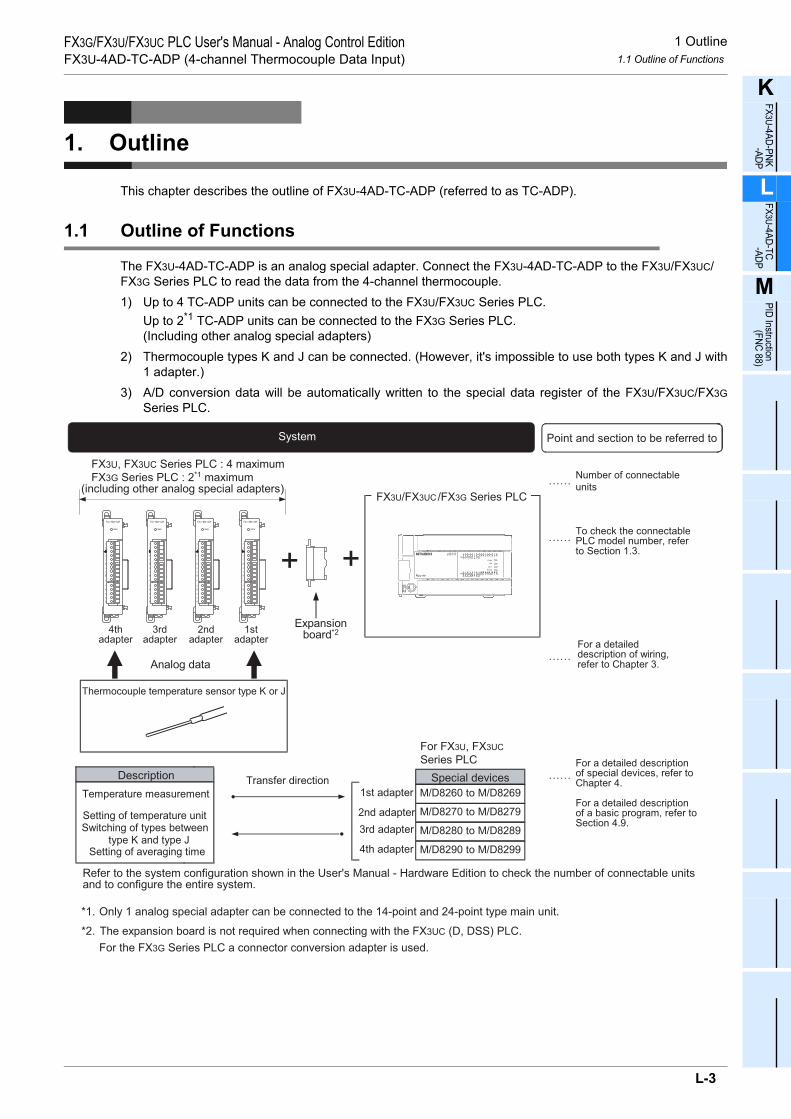
1 Outline1.1 Outline of Functions
FX3G/FX3U/FX3UC PLC User's Manual - Analog Control EditionFX3U-4AD-TC-ADP (4-channel Thermocouple Data Input)
K
FX3U-4AD-PNK -ADP
L
FX3U-4AD-TC -ADP
M
PID Instruction (FNC 88)
1. Outline
This chapter describes the outline of FX3U-4AD-TC-ADP (referred to as TC-ADP).
1.1 Outline of Functions
The FX3U-4AD-TC-ADP is an analog special adapter. Connect the FX3U-4AD-TC-ADP to the FX3U/FX3UC/FX3G Series PLC to read the data from the 4-channel thermocouple.1) Up to 4 TC-ADP units can be connected to the FX3U/FX3UC Series PLC.
Up to 2*1 TC-ADP units can be connected to the FX3G Series PLC.(Including other analog special adapters)
2) Thermocouple types K and J can be connected. (However, it's impossible to use both types K and J with1 adapter.)
3) A/D conversion data will be automatically written to the special data register of the FX3U/FX3UC/FX3GSeries PLC.
Number of connectable
units
……For a detaileddescription of wiring,refer to Chapter 3.
……To check the connectablePLC model number, referto Section 1.3.
Point and section to be referred toSystem
……
Special devices ……For a detailed descriptionof special devices, refer toChapter 4.
For a detailed descriptionof a basic program, refer toSection 4.9.
Analog data
Refer to the system configuration shown in the User's Manual - Hardware Edition to check the number of connectable unitsand to configure the entire system.
*2. The expansion board is not required when connecting with the FX
For the FX3G Series PLC a connector conversion adapter is used.
3UC (D, DSS) PLC.
FX3U, FX3UC Series PLC : 4 maximum
FX3G Series PLC : 2*1 maximum(including other analog special adapters)
1st adapter M/D8260 to M/D8269
M/D8270 to M/D8279
M/D8280 to M/D8289
M/D8290 to M/D8299
2nd adapter
3rd adapter
4th adapter
++
Expansionboard*2
FX3U/FX3UC/FX3G Series PLC
For FX3U, FX3UC
Series PLC
4thadapter
3rdadapter
2ndadapter
1stadapter
Transfer direction
*1. Only 1 analog special adapter can be connected to the 14-point and 24-point type main unit.
Description
Thermocouple temperature sensor type K or J
Temperature measurement
Setting of temperature unitSwitching of types between
type K and type JSetting of averaging time
L-3

1 Outline1.2 Setup Procedure Before Starting Operation
FX3G/FX3U/FX3UC PLC User's Manual - Analog Control EditionFX3U-4AD-TC-ADP (4-channel Thermocouple Data Input)
1.2 Setup Procedure Before Starting Operation
Before starting analog input using TC-ADP, follow the procedure below to set up the system:
Specifications: •Operation environment •Performance specifications •Input characteristics
Specifications check
Refer to Chapter 2.
System configuration and selection
Wiring
Refer to Chapter 3.
FX3U-4AD-TC-ADP
System configuration: (Refer to the common pages for analog control.)•Selection of units
Refer to the commonpages.
Wiring:•Selection of sensor cable•Power supply line•Analog input line
Outline of system: •Compatible PLC version number •Compatible programming tool version number
Outline
Refer to Chapter 1.
Programming
Refer to Chapter 4.
Programming:•Details of special devices•Examples of basic programs
If the error status data or the input analog value isabnormal, refer to Chapter 5 "Troubleshooting."
L-4

1 Outline1.3 Connectable PLC and Its Version Number
FX3G/FX3U/FX3UC PLC User's Manual - Analog Control EditionFX3U-4AD-TC-ADP (4-channel Thermocouple Data Input)
K
FX3U-4AD-PNK -ADP
L
FX3U-4AD-TC -ADP
M
PID Instruction (FNC 88)
1.3 Connectable PLC and Its Version Number
TC-ADP is compatible with the following PLC.
1. Version checkSpecial data register D8001 contains information for determining the PLC version number.
→ For a detailed description of the version check, refer to A. Common Items Subsection 5.1.2.
2. How to check the manufacturer's serial numberThe year and month of production of the product can be checked on the nameplate, and on the front of the product.
→ For a detailed description of how to check the manufacturer's serial number,refer to A. Common Items Subsection 5.1.1.
1.4 Compatible Programming Tool Version Number
Use the programming tool having the following version number to create programs for TC-ADP:
1. GX Works2
2. GX Developer• FX3U/FX3UC Series PLC
• FX3G Series PLC
If a programming tool with the wrong version number is used, programming will not be possible.*1. For Ver. 8.13P to 8.24A of GX Developer, select FX3UC for the PLC type.
3. FX-30P
Compatible PLC Version number Date of productionFX3U Series PLC Ver. 2.20 or later After May 2005 (initial production)
FX3UC Series PLC Ver. 1.30 or later After August 2004
FX3G Series PLC Ver. 1.00 or later After June 2008 (initial production)
Software Version number RemarksGX Works2SW DNC-GXW2-J Ver. 1.07H or later -
GX Works2SW DNC-GXW2-E Ver. 1.08J or later -
Software Version number RemarksGX DeveloperSW D5C-GPPW-J Ver. 8.13P or later
When selecting the model, select FX3U(C)*1.GX DeveloperSW D5C-GPPW-E Ver. 8.18U or later
Software Version number RemarksGX Developer• SW D5C-GPPW-J• SW D5C-GPPW-E
Ver. 8.72A or later -
Model name Version number RemarksFX-30P Ver. 1.00 or later -
L-5

2 Specifications2.1 Generic Specifications
FX3G/FX3U/FX3UC PLC User's Manual - Analog Control EditionFX3U-4AD-TC-ADP (4-channel Thermocouple Data Input)
2. Specifications
This chapter describes the general, power supply, and performance specifications for the TC-ADP.
2.1 Generic Specifications
*1. The criterion is shown in IEC61131-2.*2. If TC-ADP is connected to the FX3UC Series PLC, direct installation is not possible.*3.
→ For a detailed description of the grounding, refer to Section 3.7.*4. If the pressure is higher than the atmospheric pressure, do not use the TC-ADP.
The TC-ADP may malfunction.
2.2 Power Supply Specifications
Item Specifications
Ambient temperature 0 to 55°C (32 to 131°F) when operating -25 to 75°C (-13 to 167°F) when stored
Relative humidity 5 to 95%RH (no condensation) when operating
Vibrationresistance*1
Frequency(Hz)
Acceleration(m/s2)
Half amplitude(mm)
Tested 10 times in each direction (X-, Y-, and Z-axis directions) (Total: 80 min, each)
DIN Rail Mounting10 - 57 - 0.035
57 - 150 4.9 -
Direct Mounting*210 to 57 − 0.075
57 to 150 9.8 −
Shock resistance*1 147 m/s2 Acceleration, Action time: 11ms, 3 times by half-sine pulse in each direction X, Y,and Z
Noise resistance Using noise simulator of:Noise voltage: 1,000Vp-p / Noise width: 1µs / Rise: 1ns / Cycle: 30 to 100Hz
Dielectric withstand voltage 500 V AC, for 1 min
Between batch of all terminals and ground terminalInsulation resistance 5MΩ or more using 500V DC
insulation resistance meter
GroundingClass D grounding (grounding resistance: 100 Ω or less) <Common grounding with a heavy electrical system is not allowed.>*3
Workingenvironment Free from corrosive or flammable gas and excessive conductive dusts
Working altitude < 2000m*4
Item SpecificationsA/D conversion circuit driving power
24V DC +20% -15%, 45mA(It is necessary to connect a 24V DC power supply to the terminal block.)
Interface driving power5V DC, 15mA (Since the internal power is supplied from the FX Series main unit, it is notnecessary to supply the power.)
PLC OtherequipmentPLC Other
equipmentPLC Otherequipment
Shared groundingGood condition
Common groundingNot allowed
Independent groundingBest condition
L-6

2 Specifications2.3 Performance Specifications
FX3G/FX3U/FX3UC PLC User's Manual - Analog Control EditionFX3U-4AD-TC-ADP (4-channel Thermocouple Data Input)
K
FX3U-4AD-PNK -ADP
L
FX3U-4AD-TC -ADP
M
PID Instruction (FNC 88)
2.3 Performance Specifications
ItemSpecifications
Centigrade (°C) Fahrenheit (°F)
Input signal Thermocouple type K or JJIS C 1602-1995
Rated temperature range
Type K -100°C to +1000°C Type K -148°F to +1832°F
Type J -100°C to +600°C Type J -148°F to +1112°F
Digital outputType K -1000 to +10000 Type K -1480 to +18320
Type J -1000 to +6000 Type J -1480 to +11120
ResolutionType K 0.4°C Type K 0.72°F
Type J 0.3°C Type J 0.54°F
Total accuracy ±(0.5% full scale +1°C)
A/D conversion time
• FX3U/FX3UC Series PLC : 200µs (The data will be updated at every scan time.)• FX3G Series PLC : 250µs (The data will be updated at every scan time.)
→For a detailed description of data update, refer to Section2.4.
Input characteristics
Insulation method• The photocoupler is used to insulate the analog input area from the PLC.• The DC/DC converter is used to insulate the power supply line from the analog input area.• Channels are not insulated from each other.
Number of I/O points occupied
0 points(This number is not related to the maximum number of input/output points of the PLC.)
0+1000°C
+10000
-100°C
-1000-110
°C
+101
0°C
+10100
-1100
• Type K
0
+600°C
+6000
-100°C
-1000-110
°C
+610
°C
+6100
-1100
•Type J
0
+18320
-1480
+18500
-1660
•Type K
+185
0° F
+1832°F
-148°F
-166
° F
0
+11120
-1480
+11300
-1660
•Type J
+113
0°F
+1112°F
-148°F
-166
°F
L-7
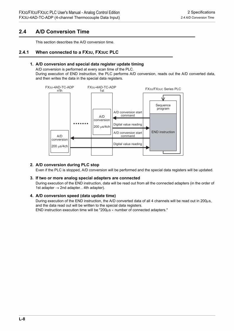
2 Specifications2.4 A/D Conversion Time
FX3G/FX3U/FX3UC PLC User's Manual - Analog Control EditionFX3U-4AD-TC-ADP (4-channel Thermocouple Data Input)
2.4 A/D Conversion Time
This section describes the A/D conversion time.
2.4.1 When connected to a FX3U, FX3UC PLC
1. A/D conversion and special data register update timingA/D conversion is performed at every scan time of the PLC.During execution of END instruction, the PLC performs A/D conversion, reads out the A/D converted data,and then writes the data in the special data registers.
2. A/D conversion during PLC stopEven if the PLC is stopped, A/D conversion will be performed and the special data registers will be updated.
3. If two or more analog special adapters are connectedDuring execution of the END instruction, data will be read out from all the connected adapters (in the order of 1st adapter → 2nd adapter…4th adapter).
4. A/D conversion speed (data update time)During execution of the END instruction, the A/D converted data of all 4 channels will be read out in 200µs, and the data read out will be written to the special data registers.END instruction execution time will be "200µs × number of connected adapters."
FX3U/FX3UC Series PLCFX3U-4AD-TC-ADP
1stFX3U-4AD-TC-ADP
n'th
A/Dconversion
200 µs/4ch
A/Dconversion
200 µs/4ch
Digital value reading
A/D conversion startcommand
END instruction
Sequenceprogram
Digital value reading
A/D conversion startcommand
L-8

2 Specifications2.5 Temperature Measurement
FX3G/FX3U/FX3UC PLC User's Manual - Analog Control EditionFX3U-4AD-TC-ADP (4-channel Thermocouple Data Input)
K
FX3U-4AD-PNK -ADP
L
FX3U-4AD-TC -ADP
M
PID Instruction (FNC 88)
2.4.2 When connected to a FX3G PLC
1. A/D conversion and special data register update timingA/D conversion is performed at every scan time of the PLC.During execution of END instruction, the PLC performs A/D conversion, reads out the A/D converted data,and then writes the data in the special data registers.
2. A/D conversion during PLC stopEven if the PLC is stopped, A/D conversion will be performed and the special data registers will be updated.
3. If two analog special adapters are connectedDuring execution of the END instruction, data will be read out from all the connected adapters (in the order of 1st adapter → 2nd adapter).
4. A/D conversion speed (data update time)During execution of the END instruction, the A/D converted data of all 4 channels will be read out in 250µs, and the data read out will be written to the special data registers.END instruction execution time will be "250µs × number of connected adapters."
2.5 Temperature Measurement
To stabilize the temperature measurement, warm-up the system for 30 minutes or more after power-on.
FX3G Series PLCFX3U-4AD-TC-ADP
1stFX3U-4AD-TC-ADP
2nd
A/Dconversion
250 µs/4ch
A/Dconversion
250 µs/4ch
Digital value reading
A/D conversion startcommand
END instruction
Sequenceprogram
Digital value reading
A/D conversion startcommand
L-9

3 WiringFX3G/FX3U/FX3UC PLC User's Manual - Analog Control EditionFX3U-4AD-TC-ADP (4-channel Thermocouple Data Input)
3. Wiring
This chapter describes the TC-ADP wiring.Observe the following caution to wire the TC-ADP.
WIRING PRECAUTIONS
• Make sure to cut off all phases of the power supply externally before attempting wiring work.Failure to do so may cause electric shock or damages to the product.
WIRING PRECAUTIONS
• Connect the DC power supply wiring to the dedicated terminals described in this manual.If an AC power supply is connected to a DC input/output terminal or DC power supply terminal, the PLC will beburnt out.
• Do not wire vacant terminals externally.Doing so may damage the product.
• Perform class D grounding (grounding resistance: 100Ω or less) to the grounding terminal on the main unit.Do not use common grounding with heavy electrical systems.
• When drilling screw holes or wiring, make sure cutting or wire debris does not enter the ventilation slits.Failure to do so may cause fire, equipment failures or malfunctions.
• Make sure to observe the following precautions in order to prevent malfunctions under the influence of noise:- Do not bundle the power line or twisted shielded cable together with or lay it close to the main circuit, high-
voltage line, or load line.Otherwise, noise disturbance and/or surge induction are likely to take place. As a guideline, lay the control line at least 100mm (3.94") or more away from the main circuit, high-voltage line, or load line.
- Ground the shield of the analog input/output cable at one point on the signal receiving side. However, do not use common grounding with heavy electrical systems.
• Make sure to properly wire to the European terminal board in accordance with the following precautions.Failure to do so may cause electric shock, equipment failures, a short-circuit, wire breakage, malfunctions, ordamage to the product.- The disposal size of the cable end should follow the dimensions described in the manual.- Tightening torque should follow the specifications in the manual.- Twist the end of strand wire and make sure there are no loose wires. - Do not solder-plate the electric wire ends.- Do not connect more than the specified number of wires or electric wires of unspecified size.- Affix the electric wires so that neither the terminal block nor the connected parts are directly stressed.
L-10

3 Wiring3.1 Terminal Layout
FX3G/FX3U/FX3UC PLC User's Manual - Analog Control EditionFX3U-4AD-TC-ADP (4-channel Thermocouple Data Input)
K
FX3U-4AD-PNK -ADP
L
FX3U-4AD-TC -ADP
M
PID Instruction (FNC 88)
3.1 Terminal Layout
The terminals of the TC-ADP are arranged as follows:
Signal Application
External power
Unused(Do not connect any lines.)
Channel-3 thermocouplesensor input
Channel-4 thermocouplesensor input
Channel-2 thermocouplesensor input
24+24-
•
L1+
L2+
L3-L4+
•
L2-
L1-
L3+
L4-
Ground terminal
J-typeJ-type
Channel-1 thermocouplesensor input
Switches the type betweentype K and type J.
24+
24-
•J-
type
J-ty
peL1
+L1
-L2
+L2
-L3
+L3
-L4
+I4
-
FX3U-4AD-TC-ADP
POWER
•
L-11
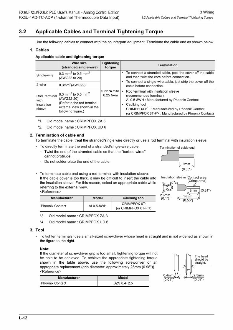
3 Wiring3.2 Applicable Cables and Terminal Tightening Torque
FX3G/FX3U/FX3UC PLC User's Manual - Analog Control EditionFX3U-4AD-TC-ADP (4-channel Thermocouple Data Input)
3.2 Applicable Cables and Terminal Tightening Torque
Use the following cables to connect with the counterpart equipment. Terminate the cable end as shown below.
1. CablesApplicable cable and tightening torque
*1. Old model name : CRIMPFOX ZA 3*2. Old model name : CRIMPFOX UD 6
2. Termination of cable endTo terminate the cable, treat the stranded/single wire directly or use a rod terminal with insulation sleeve.• To directly terminate the end of a stranded/single-wire cable:
- Twist the end of the stranded cable so that the "barbed wires" cannot protrude.
- Do not solder-plate the end of the cable.
• To terminate cable end using a rod terminal with insulation sleeve:If the cable cover is too thick, it may be difficult to insert the cable intothe insulation sleeve. For this reason, select an appropriate cable whilereferring to the external view.<Reference>
*3. Old model name : CRIMPFOX ZA 3*4. Old model name : CRIMPFOX UD 6
3. Tool• To tighten terminals, use a small-sized screwdriver whose head is straight and is not widened as shown in
the figure to the right.
Note:If the diameter of screwdriver grip is too small, tightening torque will notbe able to be achieved. To achieve the appropriate tightening torqueshown in the table above, use the following screwdriver or anappropriate replacement (grip diameter: approximately 25mm (0.98")).<Reference>
Wire size (stranded/single-wire)
Tightening torque Termination
Single-wire 0.3 mm2 to 0.5 mm2 (AWG22 to 20)
0.22 N•m to 0.25 N•m
• To connect a stranded cable, peel the cover off the cableand then twist the core before connection.
• To connect a single-wire cable, just strip the cover off thecable before connection.2-wire 0.3mm2(AWG22)
Rod terminalwithinsulation sleeve
0.3 mm2 to 0.5 mm2 (AWG22-20)(Refer to the rod terminal external view shown in the following figure.)
• Rod terminal with insulation sleeve (recommended terminal)AI 0.5-8WH : Manufactured by Phoenix Contact
• Caulking toolCRIMPFOX 6*1 : Manufactured by Phoenix Contact(or CRIMPFOX 6T-F*2 : Manufactured by Phoenix Contact)
Manufacturer Model Caulking tool
Phoenix Contact AI 0.5-8WH CRIMPFOX 6*3
(or CRIMPFOX 6T-F*4)
Manufacturer ModelPhoenix Contact SZS 0.4×2.5
9mm
Termination of cable end
(0.35")
8mm (0.31")
Contact area(Crimp area)
14mm2.6mm(0.1")
Insulation sleeve
(0.55")
0.4mm 2.5mm
The headshould bestraight.
(0.01") (0.09")
L-12

3 Wiring3.3 Power Supply Line
FX3G/FX3U/FX3UC PLC User's Manual - Analog Control EditionFX3U-4AD-TC-ADP (4-channel Thermocouple Data Input)
K
FX3U-4AD-PNK -ADP
L
FX3U-4AD-TC -ADP
M
PID Instruction (FNC 88)
3.3 Power Supply Line
Connect the 24V DC power supply line of the TC-ADP to the 24+ and 24- terminals of the terminal block.
3.3.1 To connect to the FX3G, FX3U Series PLC
Caution regarding connection of the power supply line:
• Ground the " " terminal to a class-D grounding power supply line (100Ω or less) together with the grounding terminal of the PLC main unit.
• When using an external power supply, turn it ON at the same time with the main unit or earlier than the main unit. When turning OFF the power, confirm the safety of the system, and then turn OFF the power of the PLC (including special adapter) at the same time.
3.3.2 To connect to the FX3UC Series PLC
Cautions regarding connection of the power supply line:• For the 24V DC power supply line, be sure to use the same power as the FX3UC Series PLC.
• Ground the " " terminal to a class-D grounding power supply line (100Ω or less) together with the ground terminal of the PLC main unit.
24V DCClass-D
grounding
Terminalblock
TC-ADP FX3G/FX3U
Series PLC(Main unit)+5V
24+24-
1. To use an external power
Class-Dgrounding
Terminalblock
TC-ADP
+5V
24+24- 24V0V
2. To use the 24V DC power of the PLC
FX3G/FX3U
Series PLC(Main unit)
24V DCClass-D
grounding
Terminalblock
TC-ADP
GreenRedBlack
FX3UC Series PLC(Main unit)
Powerconnector
24+24- 24+24- 24+24-
Powerconnector
Powercrossoverconnector
RedBlack
FX2NCSeries PLC
(Input extensionblock)
+5V
24+24-
L-13

3 Wiring3.4 Selection of the Thermocouple
FX3G/FX3U/FX3UC PLC User's Manual - Analog Control EditionFX3U-4AD-TC-ADP (4-channel Thermocouple Data Input)
3.4 Selection of the Thermocouple
3.4.1 Thermocouple type
• There are 2 types of thermocouples: K type and J type. When selecting the thermocouple type, make sure that the same type of thermocouple is connection to all the channels.
• Be sure to use a non-grounded thermocouple type.
3.4.2 Compensating lead wire
To connect the thermocouple, use one of the following types of compensating lead wires:
• The compensating lead wire indicates a temperature value of approximately 0.12°C higher than that of the wire resistor (10Ω). Use the appropriate compensating lead wire when considering this difference.
• If the compensating lead wire is very long, the wire may be easily affected by noise, etc. It is, therefore, recommended for the length of the compensating lead wire to be 100 m or less.
3.5 Wiring of Thermocouple
Wiring depends on the thermocouple type selected. Refer to the following wiring diagrams:
3.5.1 Wiring of thermocouple type K
*1. It is not necessary to connect lines to the J-type terminals. Leave these terminals disconnected.*2. Keep the thermocouple away from inductive noise (commercial power, etc.).
Thermocouple Type of compensating lead wireType K KX,KCA,KCB,KCC
Type J JX
3kΩ ch
TC-ADP
Class-Dgrounding
+5V
L +L -
24+24-
Compensatinglead wire
Terminal block
24V DC
L +, L -, ch : represents the channel number.
Type JType J
Thermocoupletype K*2
chL +L -
3kΩ
Temperaturecompensating circuit
Temperaturecompensating circuit
Shield
OPEN*1
L-14

3 Wiring3.6 Caution Regarding Wiring
FX3G/FX3U/FX3UC PLC User's Manual - Analog Control EditionFX3U-4AD-TC-ADP (4-channel Thermocouple Data Input)
K
FX3U-4AD-PNK -ADP
L
FX3U-4AD-TC -ADP
M
PID Instruction (FNC 88)
3.5.2 Wiring of the thermocouple type J
*1. To use a J thermocouple type, be sure to connect the thermocouple to these terminals. In addition, select J type by turning on the type K/J selection special auxiliary relay.
*2. Keep the thermocouple away from inductive noise (commercial power, etc.).
3.6 Caution Regarding Wiring
• It is not possible to connect different types of thermocouples to 4 channels of TC-ADP. Be sure to use the same type of thermocouple for all the channels.
• TC-ADP is not insulated between the channels. For this reason, be sure to use a non-grounded type thermocouple.
• Be sure not to connect to the terminal "•".
3.7 Grounding
Grounding should be performed as stated below.• The grounding resistance should be 100Ω or less.• Independent grounding should be performed for best results.
When independent grounding is not performed, perform "shared grounding" as shown in the following figure.
→ For details, refer to the User’s Manual - Hardware Edition of the PLC Series.
• The grounding wire size should be AWG22 to 20 (0.3 to 0.5 mm2).• The grounding point should be close to the PLC, and all grounding wires should be as short as possible.
3kΩ ch
TC-ADP
Class-Dgrounding
+5V
L +L -
24+24-
Terminal block
24V DC
L +, L -, ch : represents the channel number.
type J
Thermocoupletype J*2
chL +L -
3kΩ
Shield
*1Compensatinglead wire
Temperaturecompensating circuit
Temperaturecompensating circuit
type J
PLC OtherequipmentPLC Other
equipmentPLC Otherequipment
Shared groundingGood condition
Common groundingNot allowed
Independent groundingBest condition
L-15
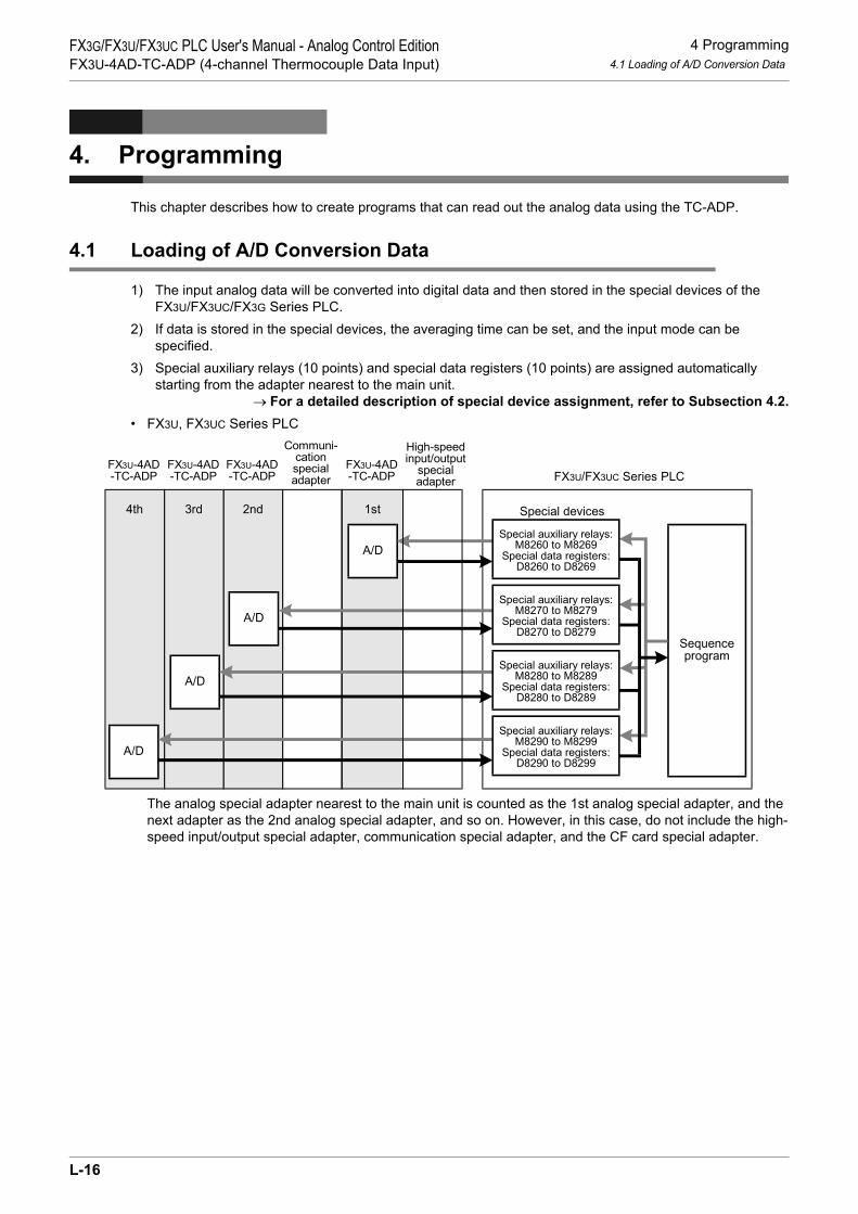
4 Programming4.1 Loading of A/D Conversion Data
FX3G/FX3U/FX3UC PLC User's Manual - Analog Control EditionFX3U-4AD-TC-ADP (4-channel Thermocouple Data Input)
4. Programming
This chapter describes how to create programs that can read out the analog data using the TC-ADP.
4.1 Loading of A/D Conversion Data
1) The input analog data will be converted into digital data and then stored in the special devices of the FX3U/FX3UC/FX3G Series PLC.
2) If data is stored in the special devices, the averaging time can be set, and the input mode can be specified.
3) Special auxiliary relays (10 points) and special data registers (10 points) are assigned automatically starting from the adapter nearest to the main unit.
→ For a detailed description of special device assignment, refer to Subsection 4.2.• FX3U, FX3UC Series PLC
The analog special adapter nearest to the main unit is counted as the 1st analog special adapter, and the next adapter as the 2nd analog special adapter, and so on. However, in this case, do not include the high-speed input/output special adapter, communication special adapter, and the CF card special adapter.
Sequenceprogram
Special devices
A/D
A/D
A/D
A/D
Communi-cationspecialadapter
FX3U-4AD-TC-ADP
FX3U-4AD-TC-ADP
FX3U-4AD-TC-ADP
FX3U-4AD-TC-ADP FX3U/FX3UC Series PLC
1st2nd3rd4th
High-speedinput/output
specialadapter
Special auxiliary relays:M8280 to M8289
Special data registers:D8280 to D8289
Special auxiliary relays:M8270 to M8279
Special data registers:D8270 to D8279
Special auxiliary relays:M8260 to M8269
Special data registers:D8260 to D8269
Special auxiliary relays:M8290 to M8299
Special data registers:D8290 to D8299
L-16

4 Programming4.1 Loading of A/D Conversion Data
FX3G/FX3U/FX3UC PLC User's Manual - Analog Control EditionFX3U-4AD-TC-ADP (4-channel Thermocouple Data Input)
K
FX3U-4AD-PNK -ADP
L
FX3U-4AD-TC -ADP
M
PID Instruction (FNC 88)
• FX3G Series PLC
The analog special adapter nearest to the main unit is counted as the 1st analog special adapter, and the next adapter as the 2nd analog special adapter. However, in this case, do not include the connector conversion adapter and the communication special adapter.
*1. The second special adapter is not available in the FX3G Series PLC(14-point and 24-point type).
2nd*1 1st
Communi-
cation
special
adapter
Connector
conversion
adapter
FX3U-4AD
-TC-ADP
FX3U-4AD
-TC-ADP
Sequence
Program
FX3G Series PLC
Special devices
Special auxiliary relays:
M8280 to M8289
Special data registers:
D8280 to D8289
Special auxiliary relays:
M8290 to M8299
Special data registers:
D8290 to D8299
A/D
A/D
L-17

4 Programming4.2 List of Special Devices
FX3G/FX3U/FX3UC PLC User's Manual - Analog Control EditionFX3U-4AD-TC-ADP (4-channel Thermocouple Data Input)
4.2 List of Special Devices
If TC-ADP is connected, special devices will be assigned automatically as shown in the following table:• FX3U, FX3UC Series PLC
R: Read / W: Write
Special device
Device numberDescription Attribute Refer to
1st 2nd 3rd 4th
Special auxiliaryrelay
M8260 M8270 M8280 M8290 Selects the temperature unit R/W Section 4.3
M8261 M8271 M8281 M8291 Switches the thermocouple type between type K and type J R/W Section
4.4M8262 to M8269
M8272 to M8279
M8282 to M8289
M8292 to M8299 Unused (Do not use.) - -
Specialdataregister
D8260 D8270 D8280 D8290 Channel-1 temperature measurement data R
Section 4.5
D8261 D8271 D8281 D8291 Channel-2 temperature measurement data R
D8262 D8272 D8282 D8292 Channel-3 temperature measurement data R
D8263 D8273 D8283 D8293 Channel-4 temperature measurement data R
D8264 D8274 D8284 D8294 Averaging time for channel 1 (Setting range: 1 to 4095) R/W
Section 4.6
D8265 D8275 D8285 D8295 Averaging time for channel 2 (Setting range: 1 to 4095) R/W
D8266 D8276 D8286 D8296 Averaging time for channel 3 (Setting range: 1 to 4095) R/W
D8267 D8277 D8287 D8297 Averaging time for channel 4 (Setting range: 1 to 4095) R/W
D8268 D8278 D8288 D8298 Error status R/W Section 4.7
D8269 D8279 D8289 D8299 Model code = 10 R Section 4.8
L-18

4 Programming4.3 Selection of Temperature Unit
FX3G/FX3U/FX3UC PLC User's Manual - Analog Control EditionFX3U-4AD-TC-ADP (4-channel Thermocouple Data Input)
K
FX3U-4AD-PNK -ADP
L
FX3U-4AD-TC -ADP
M
PID Instruction (FNC 88)
• FX3G Series PLCR: Read / W: Write
4.3 Selection of Temperature Unit
The state of special auxiliary relays decides the TC-ADP's temperature unit as shown in the table below.To switch the temperature unit, use the following special auxiliary relays:• FX3U, FX3UC Series PLC
• FX3G Series PLC
1. Program Example (For FX3U, FX3UC Series PLC)
Special deviceDevice number
Description Attribute Refer to1st 2nd
Special auxiliary relay
M8280 M8290 Selects the temperature unit R/W Section 4.3
M8281 M8291 Switches the thermocouple type between type K and type J R/W Section 4.4
M8282 to M8289
M8292 to M8299 Unused (Do not use.) - -
Special data register
D8280 D8290 Channel-1 temperature measurement data R
Section 4.5D8281 D8291 Channel-2 temperature measurement
data R
D8282 D8292 Channel-3 temperature measurement data R
D8283 D8293 Channel-4 temperature measurement data R
D8284 D8294 Averaging time for channel 1 (Setting range: 1 to 4095) R/W
Section 4.6D8285 D8295 Averaging time for channel 2
(Setting range: 1 to 4095) R/W
D8286 D8296 Averaging time for channel 3 (Setting range: 1 to 4095) R/W
D8287 D8297 Averaging time for channel 4 (Setting range: 1 to 4095) R/W
D8288 D8298 Error status R/W Section 4.7D8289 D8299 Model code = 10 R Section 4.8
Special auxiliary relayDescription
1st 2nd 3rd 4th
M8260 M8270 M8280 M8290Selection of temperature unit:OFF: Centigrade (°C)ON: Fahrenheit (°F)
Special auxiliary relayDescription
1st 2nd
M8280 M8290Selection of temperature unit:OFF: Centigrade (°C)ON: Fahrenheit (°F)
1)To switch the temperature unit to centigrade (°C) for the 1st adapter:
M8001M8260
Normally OFF
2) To switch the temperature unit to Fahrenheit (°F) for the 2nd adapter:
M8000M8270
Normally ON
L-19

4 Programming4.4 Selection of Type K or J
FX3G/FX3U/FX3UC PLC User's Manual - Analog Control EditionFX3U-4AD-TC-ADP (4-channel Thermocouple Data Input)
4.4 Selection of Type K or J
Turn on the J type or off the K type selection special auxiliary relay to select the thermocouple type J or K for TC-ADP. The thermocouple type will be selected for all the channels at the same time.To select the thermocouple type, use the following special auxiliary relays:• FX3U, FX3UC Series PLC
• FX3G Series PLC
1. Program Example (For FX3U, FX3UC Series PLC)
Special auxiliary relayDescription
1st 2nd 3rd 4th
M8261 M8271 M8281 M8291Selection of type K or J:OFF: Type KON: Type J
Special auxiliary relayDescription
1st 2nd
M8281 M8291Selection of type K or J:OFF: Type KON: Type J
2)To select thermocouple type J for the 2nd adapter :
M8000M8271
Normally ON
1) To select thermocouple type K for the 1st adapter:
M8001M8261
Normally OFF
L-20

4 Programming4.5 Temperature Measurement
FX3G/FX3U/FX3UC PLC User's Manual - Analog Control EditionFX3U-4AD-TC-ADP (4-channel Thermocouple Data Input)
K
FX3U-4AD-PNK -ADP
L
FX3U-4AD-TC -ADP
M
PID Instruction (FNC 88)
4.5 Temperature Measurement
The temperature data input in the TC-ADP will be stored in the special data registers.The special data registers that store the temperature data are shown in the following table:• FX3U, FX3UC Series PLC
• FX3G Series PLC
The immediate data or the average data (data averaged in accordance with the specified averaging time) will be stored in the above data registers as the temperature measurement data.
→ For a detailed description of the averaging time, refer to Section 4.6.
1. Caution regarding temperature measurementThe temperature measurement data are for reading only.Do not change (rewrite) the current data using the sequence program, indicator, or device monitor of the programming tool.
2. Program Example (For FX3U, FX3UC Series PLC)
Even if the temperature measurement data is not stored in D100 or D101, data registers D8260 or D8261 can be directly used in the arithmetic operation instruction or a PID instruction.
Special data registerDescription
1st 2nd 3rd 4thD8260 D8270 D8280 D8290 Stores the channel-1 temperature measurement data.
D8261 D8271 D8281 D8291 Stores the channel-2 temperature measurement data.
D8262 D8272 D8282 D8292 Stores the channel-3 temperature measurement data.
D8263 D8273 D8283 D8293 Stores the channel-4 temperature measurement data.
Special data registerDescription
1st 2ndD8280 D8290 Stores the channel-1 temperature measurement data.
D8281 D8291 Stores the channel-2 temperature measurement data.
D8282 D8292 Stores the channel-3 temperature measurement data.
D8283 D8293 Stores the channel-4 temperature measurement data.
M8000
NormallyON
FNC 12MOV
D8260 D100
FNC 12MOV
D8261 D101
Stores the channel-1 temperature measurement dataof the 1st analog special adapter in the D100.
Stores the channel-2 temperature measurement dataof the 1st analog special adapter in the D101.
L-21

4 Programming4.6 Averaging Time
FX3G/FX3U/FX3UC PLC User's Manual - Analog Control EditionFX3U-4AD-TC-ADP (4-channel Thermocouple Data Input)
4.6 Averaging Time
Setting range: 1 to 4095Initial value: K64
Numeric data type: Decimal (K)If the averaging time is set for the TC-ADP, the averaged temperature measurement data will be stored in the D8260 to D8263, D8270 to D8273, D8280 to D8283, and D8290 to D8293. The averaging time can be set for each channel.Set the averaging time in the following special data registers:• FX3U, FX3UC Series PLC
• FX3G Series PLC
1. Cautions regarding averaging time setting• If the averaging time is set to "1", the immediate data will be stored in the temperature measurement
special data register.• If the averaging time is set to "2" or more, the average value will be calculated in accordance with the set
averaging time, and the average value obtained will be stored in the temperature measurement special data register.
• After turning the PLC power on, the average data will be stored in the temperature measurement special data registers (D8260 to D8263, D8270 to D8273, D8280 to D8283, and D8290 to D8293) until the number of data items is increased to the set averaging time.
• Set the averaging time in the range from 1 to 4095. If the set value is outside the setting range, the error signal will be output.
• If the averaging time is set to "0" or smaller, the PLC will perform as if the averaging time is set to "1".If the averaging time is set to "4096" or larger, the PLC will perform as if the averaging time is set to "4096".
→ For a detailed description of error status, refer to Section 5.5
2. Program Example (For FX3U, FX3UC Series PLC)
Special data registerDescription
1st 2nd 3rd 4thD8264 D8274 D8284 D8294 Averaging time for channel-1 data
D8265 D8275 D8285 D8295 Averaging time for channel-2 data
D8266 D8276 D8286 D8296 Averaging time for channel-3 data
D8267 D8277 D8287 D8297 Averaging time for channel-4 data
Special data registerDescription
1st 2ndD8284 D8294 Averaging time for channel-1 data
D8285 D8295 Averaging time for channel-2 data
D8286 D8296 Averaging time for channel-3 data
D8287 D8297 Averaging time for channel-4 data
M8000
NormallyON
FNC 12MOV
K32 D8264
FNC 12MOV
K128 D8265
Sets the averaging time to "32" for the channel-1data of the 1st analog special adapter.
Sets the averaging time to "128" for the channel-2data of the 1st analog special adapter.
L-22

4 Programming4.7 Error Status
FX3G/FX3U/FX3UC PLC User's Manual - Analog Control EditionFX3U-4AD-TC-ADP (4-channel Thermocouple Data Input)
K
FX3U-4AD-PNK -ADP
L
FX3U-4AD-TC -ADP
M
PID Instruction (FNC 88)
4.7 Error Status
If an error is detected on TC-ADP, the error status data will be stored in the corresponding special data register.The following table shows the special data registers that store the error status data:• FX3U, FX3UC Series PLC
• FX3G Series PLC
Check the ON/OFF status of each bit of the error status data register to determine the error. Errors are assigned to the bits as shown in the following table. Create a program to detect errors.
1. Caution regarding use of error status dataIf a TC-ADP hardware error (b6) or TC-ADP communication data error (b7) is once detected, it is necessary to clear the error status with a program at next power-on of the PLC.For this reason, be sure to create the following program:• For FX3G, FX3U, FX3UC Series PLC
*1. "1st" for the FX3G PLC.
Special data registerDescription
1st 2nd 3rd 4thD8268 D8278 D8288 D8298 Stores the error status data.
Special data registerDescription
1st 2ndD8288 D8298 Stores the error status data.
Bit Description Bit Description
b0The temperature measurement data of channel 1 is outside the specified range, or disconnection is detected.
b5 Averaging time setting error
b1The temperature measurement data of channel 2 is outside the specified range, or disconnection is detected.
b6 TC-ADP hardware error
b2The temperature measurement data of channel 3 is outside the specified range, or disconnection is detected.
b7 TC-ADP communication data error
b3The temperature measurement data of channel 4 is outside the specified range, or disconnection is detected.
b8 to b15 Unused
b4 EEPROM error - -
Error status in the 3rd*1 analog special adapterb6 = OFF (hardware error)
Error status in the 3rd*1 analog special adapterb7 = OFF (communication data error)
M8002
Initial pulse
Normally
ON
RST M6
RST M7
M8000
MOV K4M0 D8288
MOV D8288 K4M0
L-23

4 Programming4.7 Error Status
FX3G/FX3U/FX3UC PLC User's Manual - Analog Control EditionFX3U-4AD-TC-ADP (4-channel Thermocouple Data Input)
• For FX3U, FX3UC Series PLC
2. Program Example 1 (For FX3G, FX3U, FX3UC Series PLC)
*1. "1st" for the FX3G PLC.
Error status in the 1st analog special adapterb6 = OFF (hardware error)
Error status in the 1st analog special adapterb7 = OFF (communication data error)
M8002
Initial pulseRST D8268.6
RST D8268.7
Y000M0
M1
M2
M3
M4
M5
M6
M7
Y001
Y002
Y003
Y004 EEPROM error in 3rd*1 adapter
Y005
Y006
Y007
Averaging time setting error in 3rd*1
adapter
TC-ADP hardware error in 3rd*1
adapter
TC-ADP communication data errorin the 3rd*1 adapter
The temperature measurement data
of channel 1 is outside the specified
range, or disconnection is detected.
The temperature measurement data
of channel 2 is outside the specified
range, or disconnection is detected.
The temperature measurement data
of channel 3 is outside the specified
range, or disconnection is detected.
The temperature measurement data
of channel 4 is outside the specified
range, or disconnection is detected.
M8000MOV D8288 K4M0
L-24

4 Programming4.7 Error Status
FX3G/FX3U/FX3UC PLC User's Manual - Analog Control EditionFX3U-4AD-TC-ADP (4-channel Thermocouple Data Input)
K
FX3U-4AD-PNK -ADP
L
FX3U-4AD-TC -ADP
M
PID Instruction (FNC 88)
3. Program Example 2 (For FX3U, FX3UC Series PLC)
Y000D8268.0
Y001D8268.1
Y002D8268.2
Y003D8268.3
Y004D8268.4
EEPROM error in 1st adapter
Y005D8268.5
Y006D8268.6
Y007D8268.7
Averaging time setting error in 1stadapter
TC-ADP hardware error in 1stadapter
TC-ADP communication data errorin the 1st adapter
The temperature measurement data
of channel 1 is outside the specified
range, or disconnection is detected.
The temperature measurement data
of channel 2 is outside the specified
range, or disconnection is detected.
The temperature measurement data
of channel 3 is outside the specified
range, or disconnection is detected.
The temperature measurement data
of channel 4 is outside the specified
range, or disconnection is detected.
L-25
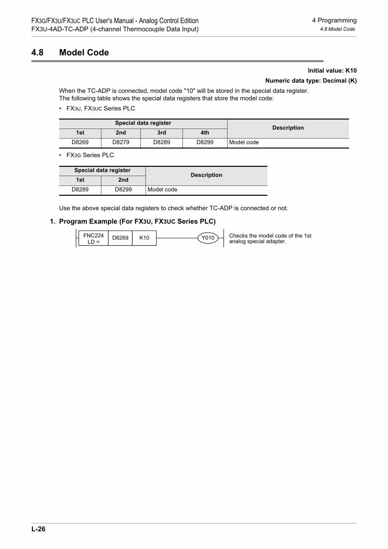
4 Programming4.8 Model Code
FX3G/FX3U/FX3UC PLC User's Manual - Analog Control EditionFX3U-4AD-TC-ADP (4-channel Thermocouple Data Input)
4.8 Model Code
Initial value: K10Numeric data type: Decimal (K)
When the TC-ADP is connected, model code "10" will be stored in the special data register.The following table shows the special data registers that store the model code:• FX3U, FX3UC Series PLC
• FX3G Series PLC
Use the above special data registers to check whether TC-ADP is connected or not.
1. Program Example (For FX3U, FX3UC Series PLC)
Special data registerDescription
1st 2nd 3rd 4thD8269 D8279 D8289 D8299 Model code
Special data registerDescription
1st 2ndD8289 D8299 Model code
FNC224LD =
D8269 K10 Checks the model code of the 1stanalog special adapter.Y010
L-26

4 Programming4.9 Basic Program Example
FX3G/FX3U/FX3UC PLC User's Manual - Analog Control EditionFX3U-4AD-TC-ADP (4-channel Thermocouple Data Input)
K
FX3U-4AD-PNK -ADP
L
FX3U-4AD-TC -ADP
M
PID Instruction (FNC 88)
4.9 Basic Program Example
Create the following basic program to read out the temperature measurement data.• For FX3G, FX3U, FX3UC Series PLCsThe following program will select thermocouple type K and will store the temperature measurement data (°C) of channels 1 and 2 of the 3rd*1 adapter in the D100 and the D101, respectively. The averaging time will be set to "32" for channel 1, and "128" for channel 2.
Even if the temperature measurement data is not stored to D100 or D101, data registers D8280 or D8281 can be directly used in the arithmetic operation instruction or a PID instruction.
*1. "1st" for the FX3G PLC.
M8002
M8001M8280 Sets the temperature unit to
centigrade (°C)
M8002FNC 12
MOVK32 D8284
FNC 12MOV
K128 D8285
Sets the averaging time to "32" forchannel-1 data
Sets the averaging time to "128" forchannel-2 data
M8281 Selects thermocouple type K
RST M6
RST M7
Error status of 3rd*1 analog specialadapterb6 = OFF (hardware error)
Error status of 3rd*1 analog specialadapterb7 = OFF (communication data error)
M8000FNC 12
MOVD8280 D100
FNC 12MOV
D8281 D101
Stores the current value of thechannel-1 measurementtemperature data to D100.
Stores the current value of thechannel-2 measurementtemperature data to D101.
M8000
Normally
ON
Initial
pulse
MOV D8288 K4M0
MOV K4M0 D8288
L-27

4 Programming4.9 Basic Program Example
FX3G/FX3U/FX3UC PLC User's Manual - Analog Control EditionFX3U-4AD-TC-ADP (4-channel Thermocouple Data Input)
• For FX3U, FX3UC Series PLCThe following program will select thermocouple type K and will store the temperature measurement data (°C)of channels 1 and 2 of the 1st adapter in the D100 and the D101, respectively. The averaging time will be setto "32" for channel 1, and "128" for channel 2.
Even if the temperature measurement data is not stored to D100 or D101, data registers D8260 or D8261 can be directly used in the arithmetic operation instruction or a PID instruction.
M8002
M8001M8260 Sets the temperature unit to
centigrade (°C)
M8002FNC 12
MOVK32 D8264
FNC 12MOV
K128 D8265
Sets the averaging time to "32" forchannel-1 data
Sets the averaging time to "128" forchannel-2 data
M8261 Selects thermocouple type K
RST D8268.6
RST D8268.7
Error status of 1st analog specialadapterb6 = OFF (hardware error)
Error status of 1st analog specialadapterb7 = OFF (communication data error)
M8000FNC 12
MOVD8260 D100
FNC 12MOV
D8261 D101
Stores the current value of thechannel-1 measurementtemperature data to D100.Stores the current value of thechannel-2 measurementtemperature data to D101.
L-28
5 Troubleshooting5.1 PLC Version Number Check
FX3G/FX3U/FX3UC PLC User's Manual - Analog Control EditionFX3U-4AD-TC-ADP (4-channel Thermocouple Data Input)
K
FX3U-4AD-PNK -ADP
L
FX3U-4AD-TC -ADP
M
PID Instruction (FNC 88)
5. Troubleshooting
This chapter describes the troubleshooting methods and error status.If the temperature measurement data is not input, or if the proper digital value is not input, check the followingitems:• Version number of the PLC• Wiring• Special devices• Programs• Error status
5.1 PLC Version Number Check
• Any versions (from Ver.2.20 (initial version) to the latest version) of the FX3U Series are compatible.• Check the version number of FX3UC Series. The version number should be 1.30 or later.• Any versions (from Ver.1.00 (initial version) to the latest version) of the FX3G Series are compatible.
→ For a detailed description of the version number check method, refer to Section 1.3.
5.2 Wiring Check
Check the following items for wiring:
1. PowerThe TC-ADP needs driving power. Verify that the power supply line is properly connected. Also check that the POWER indicator lamp of the TC-ADP is on.
2. Thermocouple cableUse a non-grounded type thermocouple and connect the thermocouple using the compensating lead wire.In addition, separate the cable of the thermocouple from the other power cables or inductive cables.
3. To use thermocouple type JTo use thermocouple type J, shortcircuit the J-type terminals. If these terminals are not shortcircuited, the temperature measurement data cannot be read out correctly.
→ For a detailed description of wiring, refer to Chapter 3.
5.3 Special Device Check
Check whether the special devices for the TC-ADP are correctly used:
1. Selection of type K or JCheck if the special device for type K/J selection is correctly set.Turn off the device to select thermocouple type K. Turn on the device to select thermocouple type J.
2. Temperature measurementCheck if the special device of the selected channel is correctly set.This special device should be selected depending on the connecting position and the channel.
3. Averaging timeVerify if the set averaging time is within the specified range. The averaging time should be set in the range from 1 to 4095. If the set averaging time is outside the specified range, an error occurs.
4. Error statusCheck that no error is detected in the TC-ADP.If an error is detected, check the details of the error, and then check the wiring and programs.
→ For a detailed description of special devices, refer to Chapter 4.
L-29

5 Troubleshooting5.4 Program Check
FX3G/FX3U/FX3UC PLC User's Manual - Analog Control EditionFX3U-4AD-TC-ADP (4-channel Thermocouple Data Input)
5.4 Program Check
Check the following items for the program:
1. Cancellation of error status at power-onWhen the power is turned off and then on again, the error status should be cleared (the b6 and the b7 shouldturn off) using the program.
2. Check of storage devicesVerify that different values are not being stored in the same device by the other parts of the programs.
5.5 Error Status Check
If an error occurs in the TC-ADP, the corresponding bit will turn on.The bit which is turned ON due to the error status is held ON until overwritten to OFF by the program or thepower is cycled. If b6 or b7 is turned ON, then it is necessary to clear the error status using the program thenext time the power of the PLC is cycled.
To solve a problem, refer to the troubleshooting method described below:
1. Temperature measurement out of specified range or disconnection of line (b0 to b3)1) Description of error
The input temperature measurement value is outside the specified range.The temperature measurement value of thermocouple type K is not in the range between -110°C to +1010°C, or the temperature measurement value of thermocouple type J is not in the range between -110°C to +610°C.Or the line between TC-ADP and the thermocouple is disconnected.
2) RemedyCheck that the input temperature measurement value is within the specified range.Also check the wiring condition.
2. EEPROM error (b4)1) Description of error
The adjustment data set in the EEPROM before delivery from our factory is unreadable or is destroyed.2) Remedy
Please contact the nearest Mitsubishi Electric distributor office.
3. Averaging time setting error (b5)1) Description of error
The averaging time set for one of the channels (channels 1 to 4) is outside the specified range: 1 to 4095.2) Remedy
Check that the averaging time is correctly set for each channel.
Bit Description Bit Description
b0The temperature measurement data of channel 1 is outside the specified range, or disconnection is detected.
b5 Averaging time setting error
b1The temperature measurement data of channel 2 is outside the specified range, or disconnection is detected.
b6 TC-ADP hardware error
b2The temperature measurement data of channel 3 is outside the specified range, or disconnection is detected.
b7 TC-ADP communication data error
b3The temperature measurement data of channel 4 is outside the specified range, or disconnection is detected.
b8 to b15 Unused
b4 EEPROM error - -
L-30

5 Troubleshooting5.5 Error Status Check
FX3G/FX3U/FX3UC PLC User's Manual - Analog Control EditionFX3U-4AD-TC-ADP (4-channel Thermocouple Data Input)
K
FX3U-4AD-PNK -ADP
L
FX3U-4AD-TC -ADP
M
PID Instruction (FNC 88)
4. TC-ADP hardware error (b6)1) Description of error
The TC-ADP does not operate properly.2) Remedy
Check that the 24V DC power is properly supplied to the TC-ADP.Also check that the TC-ADP is correctly connected to the PLC.If the problem cannot be solved even after the above check, please contact the nearest Mitsubishi Electric distributor office.
5. TC-ADP communication data error (b7)1) Description of error
A communication error is detected between the TC-ADP and the PLC.2) Remedy
Check that the TC-ADP is correctly connected to the PLC.If the problem cannot be solved even after the above check, please contact the nearest Mitsubishi Electric distributor office.
L-31

5 Troubleshooting5.5 Error Status Check
FX3G/FX3U/FX3UC PLC User's Manual - Analog Control EditionFX3U-4AD-TC-ADP (4-channel Thermocouple Data Input)
MEMO
L-32

FX3G/FX3U/FX3UC PLC User's Manual - Analog Control EditionPID Instruction (FNC 88)
K
FX3U-4AD-PNK -ADP
L
FX3U-4AD-TC -ADP
M
PID Instruction (FNC 88)
FX3G/FX3U/FX3UC Series Programmable Controllers
User's Manual [Analog Control Edition] PID Instruction (FNC 88)
Foreword
This manual describes the control methods for using the PID instruction in combination with analog products and should be read and understood before attempting to install or use the unit.Store this manual in a safe place so that you can take it out and read it whenever necessary. Always forward it to the end user.
© 2005 MITSUBISHI ELECTRIC CORPORATION
This manual confers no industrial property rights or any rights of any other kind, nor does it confer any patentlicenses. Mitsubishi Electric Corporation cannot be held responsible for any problems involving industrial propertyrights which may occur as a result of using the contents noted in this manual.
M-1

FX3G/FX3U/FX3UC PLC User's Manual - Analog Control EditionPID Instruction (FNC 88)
M-2

FX3G/FX3U/FX3UC PLC User's Manual - Analog Control EditionPID Instruction (FNC 88)
1 Outline1.1 Outline of function
K
FX3U-4AD-PNK -ADP
L
FX3U-4AD-TC -ADP
M
PID Instruction (FNC 88)
1. Outline
This chapter describes the outline of PID instruction (FNC88) for the FX3U/FX3UC/FX3G Series PLC.
1.1 Outline of function
The PID instruction requires the system to calculate the output (MV) value from the measured (PV) value. Through combining the P (proportional) action, I (integral) action, and D (derivative) action the target (SV) value can be obtained. See diagram below.1) Alarm output function
The alarm function can be set for input variation (measured value) or output variation (value).2) Setting limit values
The upper limit and lower limit can be set for the output value.3) Auto-tuning function
The proportional gain (KP), integral time (TI) and differential time (TD) can be set automatically for boththe limit cycle method and step response method.
4) Operation method of the PID instructionBoth PID speed type operation and measured value differential type operation are executed.
FX3U/FX3UC/FX3G Series PLC
Controlledobject
Measured value (PV)
Output value (MV)
Target value(SV)
PID Instruction
M-3

1 OutlineFX3G/FX3U/FX3UC PLC User's Manual - Analog Control EditionPID Instruction (FNC 88) 1.2 Basic Operation Expressions in PID Instruction (Reference)
1.2 Basic Operation Expressions in PID Instruction (Reference)
The PID instruction executes using the speed type or measured value differential type operation expression.According to the contents of +1, bit 0 (operation setting (ACT)) specified by in the PID control,either for forward operation or backward operation is executed.Each value required in the operation is specified by a corresponding parameter or later.
1. Basic operation expression for PID control
1) SymbolsEVn : Deviation in sampling at this time Dn : Differential term at this timeEVn-1 : Deviation in previous cycle Dn-1 : Differential term in previous cycleSV : Target value KP : Proportional gainPVnf : Measured value in sampling at this time (after filter) TS : Sampling cyclePVnf-1 : Measured value in previous cycle (after filter) TI : Integral constantPVnf-2 : Measured value in two cycles before (after filter) TD : Differential constant∆MV : Output variation KD : Differential gainMVn : Operation quantity at this time
2) Expression for calculating the measured value (after the filter) in sampling at this time (PVnf)The value "PVnf" is obtained from the following expression based on the read measured value.
Measured value after filter: PVnf = PVn+L(PVnf-1-PVn)
PVn : Measured value in sampling at this timeL : Filter coefficientPVnf-1 : Measured value in previous cycle (after filter)
Operation direction (ACT)
+1, b0PID operation expression
Forward operation(OFF)
Backwardoperation (ON)
S3 S3
S3
S3S3
∆MV = KP(EVn − EVn-1) + EVn + Dn
EVn = PVnf-SV
Dn = (−2PVnf−1 + PVnf + PVnf−2) + Dn-1
MVn = Σ∆MV
TS
TI
TD
TS + KD TD
KD TD
TS + KD TD
∆MV = KP(EVn − EVn−1) + EVn + Dn
EVn = SV − PVnf
Dn = (2PVnf−1 − PVnf − PVnf−2) + Dn-1
MVn = Σ∆MV
TS
TI
TD
TS + KD TD
KD TD
TS + KD TD
M-4
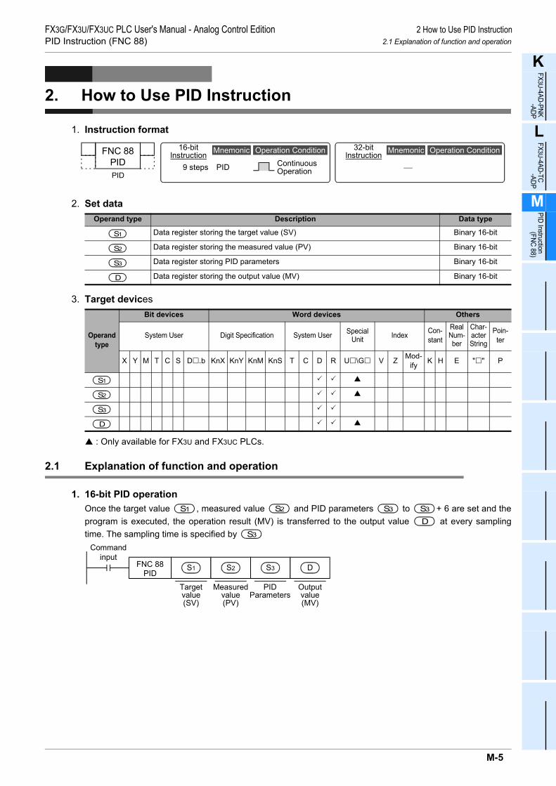
FX3G/FX3U/FX3UC PLC User's Manual - Analog Control EditionPID Instruction (FNC 88)
2 How to Use PID Instruction2.1 Explanation of function and operation
K
FX3U-4AD-PNK -ADP
L
FX3U-4AD-TC -ADP
M
PID Instruction (FNC 88)
2. How to Use PID Instruction
1. Instruction format
2. Set data
3. Target devices
: Only available for FX3U and FX3UC PLCs.
2.1 Explanation of function and operation
1. 16-bit PID operationOnce the target value , measured value and PID parameters to + 6 are set and theprogram is executed, the operation result (MV) is transferred to the output value at every samplingtime. The sampling time is specified by
Operand type Description Data type
Data register storing the target value (SV) Binary 16-bit
Data register storing the measured value (PV) Binary 16-bit
Data register storing PID parameters Binary 16-bit
Data register storing the output value (MV) Binary 16-bit
Operand type
Bit devices Word devices Others
System User Digit Specification System User Special Unit Index Con-
stant
Real Num-ber
Char-acter String
Poin-ter
X Y M T C S D .b KnX KnY KnM KnS T C D R U \G V Z Mod-ify K H E " " P
32-bitlnstruction
⎯
Mnemonic Operation ConditionFNC 88PIDPID
16-bitlnstruction
9 steps PID ContinuousOperation
Mnemonic Operation Condition
SS1
S2
S3
D
SS1
S2
S3
D
S1S1 S2S2 S3S3 S3S3
S3DS3S3
Commandinput
FNC 88PID
S3S2S1 D
Targetvalue(SV)
Measuredvalue(PV)
PIDParameters
Outputvalue(MV)
M-5

2 How to Use PID InstructionFX3G/FX3U/FX3UC PLC User's Manual - Analog Control EditionPID Instruction (FNC 88) 2.2 Relationship Between Parameter Setting and Auto-Tuning
Explanation of set items
*1. When auto-tuning is not executed for the limit cycle method, the same number of devices as thoseoccupied in the step response method become occupied.
2.2 Relationship Between Parameter Setting and Auto-Tuning
1. When auto-tuning is not executed (parameter setting)It is necessary to write the set value of the parameters to +6 using MOV instruction in advance,etc. before starting the PID operation when auto-tuning is not executed.When data registers in the latch area are backed up against power failure, the setting data is held even afterthe power of the PLC is turned OFF. Therefore, writing is not necessary when the power is turned back ON.
2. When auto-tuning is executedThe proportional gain ( +3), integral time ( +4) and differential time ( +6) are importantconstants for executing the auto-tuning function described later and for optimizing the PID control. Theseconstants can be set automatically.
→ For a detailed description of auto-tuning (limit cycle method), refer to Section. 4.1.→ For a detailed description of auto-tuning (step response method), refer to Section. 4.2.
Set item Description Occupiedpoints
Target value(SV)
• The target value (SV) is set.• The PID instruction does not change the settings.• Caution on using the auto-tuning (limit cycle method)
If the target value for auto-tuning is different from the target value in the PIDcontrol, it is necessary to set a value to which a bias value is added, and thenstore the actual target value when the auto-tuning flag turns OFF.
1
Measuredvalue (PV) This is the input value of the PID operation. 1
Parameter*1
1) Auto-tuning (in the limit cycle)Twenty-nine devices are occupied from the head device specified in .
2) Auto-tuning (in the step response method)a) Operation setting (ACT): When bits 1, 2 and 15 are something other than "0"
Twenty-five devices are occupied from the head device specified in .b) Operation setting (ACT): When bits 1, 2 and 15 are "0"
Twenty devices are occupied from the head device specified in .
29
25
20
Output value(MV)
1) PID control (normal processing)The user sets the initial output value before driving the instruction.After that, the operation result is stored.
2) Auto-tuning (in the limit cycle method)The Upper Limit Value (ULV) or Lower Limit Value (LLV) value is automaticallyoutput during auto-tuning. The specified MV value is output when auto-tuning isfinished.
3) Auto-tuning (in the step response method)The user sets the step output value before driving the instruction.The MV value is not changed by PID instruction during auto-tuning.
1
S1
S2
S3
S3
S3
S3
D
S3 S3S3
S3S3 S3S3 S3S3
M-6

FX3G/FX3U/FX3UC PLC User's Manual - Analog Control EditionPID Instruction (FNC 88)
3 Parameter3.1 Parameter List: (S3) to (S3) + 28
K
FX3U-4AD-PNK -ADP
L
FX3U-4AD-TC -ADP
M
PID Instruction (FNC 88)
3. Parameter
This chapter describes various parameters of PID instruction.
3.1 Parameter List: (S3) to (S3) + 28
Set item Setting Remarks Reference
Sampling time (TS) 1 to 32767 (ms) It cannot be shorter than operationcycle of the PLC.
Subsection 3.2.1
+1Operationsetting (ACT)
bit0 0: Forward operation1: Backward operation Operation direction
Subsection 3.2.2
bit1 0: Input variation alarm is invalid.1: Input variation alarm is valid.
bit2 0: Output variation alarm is invalid.1: Output variation alarm is valid.
Do not set to ON bit 2 and bit 5 atsame time.
bit3 Not available
bit4 0: Auto-tuning is not executed.1: Auto-tuning is executed.
bit5
0: Upper and lower limits of outputvalue are not valid.
1: Upper and lower limits of outputvalue are valid.
Do not set to ON bit 2 and bit 5 atsame time.
bit6 0: Step response method1: Limit cycle method Select auto-tuning mode.
bit7 to bit15 Not available
+2 Input filter constant (α) 0 to 99 (%) When "0" is set, input filter is notprovided.
Subsection 3.2.3
+3 Proportional gain (KP) 1 to 32767 (%) Subsection 3.2.4
+4 Integral time (TI) 0 to 32767 (× 100 ms) When "0" is set, it is handled as "∞"(no integration).
Subsection 3.2.5
+5 Differential gain (KD) 0 to 100 (%) When "0" is set, differential gain isnot provided.
Subsection 3.2.6
+6 Differential time (TD) 0 to 32767 (× 10 ms) When "0" is set, differential is notexecuted.
Subsection 3.2.7
+7 :
+19These devices are occupied for internal processing of PID operation. Do not change data. ⎯
S3S3
S3S3
S3S3
S3S3
S3S3
S3S3
S3S3
S3S3
S3S3
M-7

3 ParameterFX3G/FX3U/FX3UC PLC User's Manual - Analog Control EditionPID Instruction (FNC 88) 3.1 Parameter List: (S3) to (S3) + 28
*1. +20 to +24 become occupied only if bits 1, 2, or 5 are set to "1" to determine the action (ACT) of+1.
+20*1 Input variation (incremental) alarm set value 0 to 32767
It is valid when operation direction (ACT) (bit 1 of +1) is "1".
Subsection 3.2.2
+21*1 Input variation (decremental) alarm set value 0 to 32767
It is valid when operation direction (ACT) (bit 1 of +1) is "1".
+22*1
Output variation (incremental) alarm set value 0 to 32767
It is valid when operation direction (ACT) (bit 2 of +1) is "1"or (ACT) (bit 5 of +1) is "0".
Output upper limit set value −32768 to 32767It is valid when operation direction (ACT) (bit 2 of +1) is "0"or (ACT) (bit 5 of +1) is "1"
+23*1
Output variation (decremental) alarm set value 0 to 32767
It is valid when operation direction (ACT) (bit 2 of +1) is "1"or (ACT) (bit 5 of +1) is "0"
Output lower limit set value −32768 to 32767It is valid when operation direction (ACT) (bit 2 of +1) is "0"or (ACT) (bit 5 of +1) is "1"
+24*1 Alarm output
bit0
0: Input variation (incremental) is not exceeded.
1: Input variation (incremental) is exceeded.
It is valid when operation direction (ACT) (bit 1 or bit 2 of +1) is "1".
Subsection 3.2.8
bit1
0: Input variation (decremental) is not exceeded.
1: Input variation (decremental) is exceeded.
bit2
0: Output variation (incremental) is not exceeded.
1: Output variation (incremental) is exceeded.
bit3
0: Output variation (decremental) is not exceeded.
1: Output variation (decremental) is exceeded.
The setting below is required when the limit cycle method is used (when the operation direction (ACT) b6 is set to ON).
+25PV value threshold (hysteresis) width (SHPV)
Set it according to measured value(PV) fluctuation.
They are occupied when operationdirection (ACT) (bit 6) is "ON (limitcycle method)."
Chapter 4
+26Output value upper limit (ULV)
Set maximum value (ULV) of outputvalue (MV).
+27Output value lower limit (LLV)
Set minimum value (LLV) of outputvalue (MV).
+28Wait setting from end of tuningcycle to start of PID control(KW)
−50 to 32717%
Set item Setting Remarks Reference
S3S3S3
S3S3S3
S3S3
S3
S3
S3
S3
S3S3
S3
S3
S3
S3
S3S3 S3
S3S3
S3S3
S3S3
S3S3
S3
S3
M-8

FX3G/FX3U/FX3UC PLC User's Manual - Analog Control EditionPID Instruction (FNC 88)
3 Parameter3.2 Details of Parameters
K
FX3U-4AD-PNK -ADP
L
FX3U-4AD-TC -ADP
M
PID Instruction (FNC 88)
3.2 Details of Parameters
3.2.1 Sampling time (TS): (S3)
Setting range: 1 to 32767 [ms]Set the cycle time (ms) for the PID operation.• In PID control and auto-tuning (Limit cycle method)
Set the sampling time longer than the operation cycle of the PLC.• In auto-tuning (Step response method)
Set the sampling time to 1,000 ms (= 1 second) or more.
1. Maximum errorThe maximum error of the sampling time (TS) is from "-(one operation cycle + 1 ms)" to "+(one operationcycle)."1) When the sampling time (TS) is a small value
Fluctuation of the maximum error described above may cause a problem.In such a case, execute the PID instruction in the constant scan mode, or program it in a timer interruptroutine.
2) When the sampling time (TS) is shorter than one operation cycle of the PLCA PID operation error (K6740) occurs, however when PID operation is executed, the sampling time (TS) isequal to the operation cycle of the PLC.In such a case, use the PID instruction in a timer interrupt (I6 to I8 ), and clear +7 just beforeexecuting the PID instruction.
→ For a detailed description, refer to FX3G/ FX3U/FX3UC Series Programming Manual - Basic & AppliedInstruction Edition
S3
X000FNC 12MOVP
K 0 D107
FNC 88PID
D 0 D 1 D100 D150
+7 is reset.(When the interrupt routine is executed for thefirst time,the register for internal processing iscleared by the pulse generation command.)
S3
I610
The PID operation isexecuted.
M-9

3 ParameterFX3G/FX3U/FX3UC PLC User's Manual - Analog Control EditionPID Instruction (FNC 88) 3.2 Details of Parameters
3.2.2 Operation setting (ACT):(S3)+1
Setting range: OFF = forward operation, ON = backward operation
1. Forward operation or backward operation: +1, bit 0Select the PID control direction (forward or backward).• During auto-tuning for the limit cycle method
It is necessary to set the PID control direction (forward or backward) for auto-tuning.• During auto-tuning for the step response method
The PID control direction (forward or backward) is not required as, the direction is automatically set when auto-tuning is complete.
Forward operation: +1, bit 0 = 0As the measured value (PV) becomes larger than the target value (SV), the output (MV) increases.For example, cooling is a forward operation.
<Cooling>
Backward operation: +1, bit 0 = 1As the measured value (PV) becomes smaller than the target value (SV), the output (MV) increases.For example, heating is a backward operation.
<Heating>
Relationship between the forward/backward operation and the output (MV), measured value (PV) andtarget value (SV)The relationship is as follows.
S3
S3
Time
Target value (SV)
Measured value (PV)
Tem
pera
ture
S3
Time
Target value (SV)
Measured value (PV)
Tem
pera
ture
Out
put (
MV
)
Backwardoperation
Target value (SV)
Forwardoperation
Measured value (PV)
M-10

FX3G/FX3U/FX3UC PLC User's Manual - Analog Control EditionPID Instruction (FNC 88)
3 Parameter3.2 Details of Parameters
K
FX3U-4AD-PNK -ADP
L
FX3U-4AD-TC -ADP
M
PID Instruction (FNC 88)
2. Alarm setting (for input variation and output variation): +1, bit 1 and bit 2Setting range: OFF, ON
The input variation and output variation can be checked arbitrarily.These parameters can be set in +24.
→ For the operation of upper/lower limit alarm output for the input and output values,refer to Subsection 3.2.8.
Input variation: +1, bit 1When using the input variation alarm, it is necessary to set to ON the following bits and set the values to bechecked.
Output variation: +1, bit 2When using the output variation alarm, it is necessary to set the following bits to ON and set the values to bechecked.
Variation means (Previous value) - (Current value)
3. Upper and lower limits for output value: +1, bit 5Setting range: OFF = Setting is not provided., ON = Setting is provided.
The upper limit and lower limit of the output value work as shown in the graph below.The upper limit and lower limit of the output value can moderate the increase of the integral item in the PIDcontrol.When using the upper limit and lower limit of the output value, make sure to set +1, bit 2 is set to OFF.
Set item Setting (setting range)Operation setting (ACT) +1 bit1 Input variation alarm ON: Used
OFF: Not used
Input variation alarm set value
+20 Input variation (incremental) alarm set value 0 to 32767
+21 Input variation (decremental) alarm set value 0 to 32767
Set item Setting (setting range)
Operation setting (ACT) +1
bit2 Output variation alarm ON: UsedOFF: Not used
bit5 Output value upper/lower limit setting Make sure to set it to OFF
Output variation alarm set value
+22 Output variation (incremental) alarm set value 0 to 32767
+23 Output variation (decremental) alarm set value 0 to 32767
Set item Setting (setting range)
Operation setting (ACT) +1(ACT)
bit2 Output variation alarm Make sure to set it to OFF
bit5 Output value upper/lower limit setting ON: UsedOFF: Not used
S3S3
S3
S3
S3
S3S3
S3S3
S3S3
S3S3
S3S3
S3S3
S3S3
S3
S3
Output valueupper limit
Output valuelower limit
Time
S3 +22
Output value
S3 +23
These valuesare not output.
These valuesare not output.
When the upper limit and lowerlimit of output value are set
When the upper limit and lowerlimit of output value are not set
M-11

3 ParameterFX3G/FX3U/FX3UC PLC User's Manual - Analog Control EditionPID Instruction (FNC 88) 3.2 Details of Parameters
3.2.3 Input filter (α): (S3)+2
Setting range: 0 to 99[%]PID control: Proportional operation, integral operation and differential operation
The input filter (α) is a software filter to reduce the fluctuation of the measured value (PV) caused by noise.By setting this time constant of the filter according to the control target characteristics and noise level, theeffect of noise can be reduced.• If the input filter value is too small, the filter effect is small.• If the input filter value is too large, the input response is bad.
Because the input filter (α) is effective to the target value (SV), all of the proportional operation, integraloperation and differential operation are affected.
Input amplitudeInput amplitude
processed by input filter
Pulse input by noiseActualmeasuredvalue (PV)
Measuredvalue (PV)processed byinput filter
M-12

FX3G/FX3U/FX3UC PLC User's Manual - Analog Control EditionPID Instruction (FNC 88)
3 Parameter3.2 Details of Parameters
K
FX3U-4AD-PNK -ADP
L
FX3U-4AD-TC -ADP
M
PID Instruction (FNC 88)
3.2.4 Proportional gain (KP): (S3)+3
Setting range: 1 to 32767[%]PID control: Proportional operation
During the proportional operation, the output (MV) increases in proportion to the deviation (differencebetween the target value (SV) and the measured value (PV)).This deviation is called proportional gain (Kp), and expressed in the following relational expression:
Output (MV) = Proportional gain (KP) x Deviation (EV)
The reciprocal of the proportional gain (KP) is called proportional band.As the proportional gain (KP) is larger (as shown in the example below), the motion to let the measured value(PV) be nearer to the target value (SV) becomes stronger.
Example 1: Proportional operation (P operation) in heating (backward operation)
Example 2: Proportional operation (P operation) in cooling (forward operation)
3.2.5 Integral time (TI): (S3)+4
Setting range: 0 to 32767 [ × 100 ms] "0" is handled as "∞" (no integration).PID operation: Integral operation
During the integral operation, the time after deviation is generated until the integral operation output becomesthe proportional operation output. This is called integral time and is expressed as "TI".As TI becomes smaller, the integral operation becomes stronger.
Time
Target value (SV)Measured value (PV)
Remaining deviationProportional gainKP3 > KP2 > KP1
KP3
KP2KP1Te
mpe
ratu
re
Time
Proportional gainKP3 > KP2 > KP1KP3 KP2 KP1
Out
put (
MV
)
Time
Tem
pera
ture
Remaining deviation Target value (SV)
Measured value (PV)
Time
Out
put (
MV
)
Proportional gainKP3 > KP2 > KP1KP3 KP2 KP1
Proportional gainKP3 > KP2 > KP1KP3 KP2 KP1
M-13
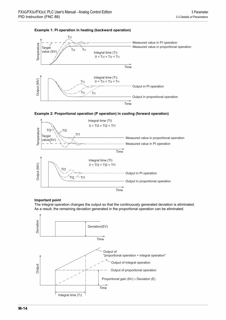
3 ParameterFX3G/FX3U/FX3UC PLC User's Manual - Analog Control EditionPID Instruction (FNC 88) 3.2 Details of Parameters
Example 1: PI operation in heating (backward operation)
Example 2: Proportional operation (P operation) in cooling (forward operation)
Important pointThe integral operation changes the output so that the continuously generated deviation is eliminated.As a result, the remaining deviation generated in the proportional operation can be eliminated.
Time
Targetvalue (SV)
Measured value in proportional operation
Tem
pera
ture
TI3
0 < TI3 < TI2 < TI1
Measured value in PI operation
TI2 TI1
Time
Output in proportional operationOut
put (
MV
)
TI3
Output in PI operation
TI2 TI1
0 < TI3 < TI2 < TI1
Integral time (TI)
Integral time (TI)
Time
Targetvalue(SV) Measured value in proportional operation
TI3
Measured value in PI operation
TI2TI1
0 < TI3 < TI2 < TI1
Time
Output in proportional operation
TI3
TI2 TI1Output in PI operation
0 < TI3 < TI2 < TI1
Integral time (TI)
Integral time (TI)
Tem
pera
ture
Out
put (
MV
)
Time
Deviation(EV)
Dev
iatio
n
Time
Output of"proportional operation + integral operation"
Output of proportional operation
Proportional gain (KP) × Deviation (E)
Output of integral operation
Integral time (TI)
Out
put
M-14

FX3G/FX3U/FX3UC PLC User's Manual - Analog Control EditionPID Instruction (FNC 88)
3 Parameter3.2 Details of Parameters
K
FX3U-4AD-PNK -ADP
L
FX3U-4AD-TC -ADP
M
PID Instruction (FNC 88)
3.2.6 Differential gain (KD): (S3)+5
Setting range: 0 to 100[%]PID control: Differential operation
The filter is applied to the output at the differential operation.Only the differential operation is affected by the differential gain (KD).• When the differential gain (KD) is small, the output is immediately given with regard to changes in the
measured value (PV) caused by disturbance, etc.• When the differential gain (KD) is large, the output is given after a long time with respect to changes in the
measured value (PV) caused by disturbance, etc.
Important pointsSet the differential gain (KD) to "0", and then adjust the operation using the input filter (α).If the output response is too close to the disturbance, increase the differential gain (KD).
3.2.7 Differential time (TD): (S3)+6
Setting range: 0 to 32767 [× 10 ms]PID control: Differential operation
Use the differential time (TD) to respond sensitively to fluctuations in the measured value (PV) caused bydisturbance, etc. and to minimize the fluctuations.• When the differential time (TD) is large, it becomes to prevent large fluctuation in the control target caused
by disturbance, etc.• It is not always necessary to use the differential time (when disturbance is small, for example).
Time
Deviation (EV)Disturbance
Dev
iatio
n
Time
TD3 (PID operation)
TD3 (PID operation)
TD2 (PID operation)
TD1 (PID operation)
TD2 (PID operation)
TD1 (PID operation)
TD3 > TD2 > TD1
Out
put (
MV
)
M-15

3 ParameterFX3G/FX3U/FX3UC PLC User's Manual - Analog Control EditionPID Instruction (FNC 88) 3.2 Details of Parameters
Example 1: PID operation in heating (backward operation)
Example 2: PID operation in cooling (forward operation)
Time
Tem
pera
ture
Changes caused by disturbance
TD3 > TD2 > TD1
PI operation (without differential operation)
Time
Out
put (
MV
)
Changes in output caused by disturbance
PI operation (without differential operation)
TD3 > TD2 > TD1TD3 (PID operation)
TD3 (PID operation)
TD2 (PID operation)
TD1 (PID operation)
TD2 (PID operation)
TD1 (PID operation)
Target value (SV)
Time
Tem
pera
ture
Changes caused by disturbance
TD3 > TD2 > TD1
Time
Out
put (
MV
)
Changes in output caused by disturbance
TD3 > TD2 > TD1
PI operation (without differential operation)
TD1 (PID operation)
TD2 (PID operation)
Target value (SV)
PI operation (without differential operation)
TD3 (PID operation)
TD1 (PID operation)TD2 (PI operation)
TD3 (PID operation)
M-16

FX3G/FX3U/FX3UC PLC User's Manual - Analog Control EditionPID Instruction (FNC 88)
3 Parameter3.2 Details of Parameters
K
FX3U-4AD-PNK -ADP
L
FX3U-4AD-TC -ADP
M
PID Instruction (FNC 88)
3.2.8 Alarm output flag: (S3)+24
When the input variation [ +1, bit 1] is set to 1
When the output variation [ +1, bit 2] is set to 1
- When the preset input/output variation is exceeded:Each bit of +24 (alarm flags) turns ON immediately after PID instruction execution.
S3
Time
Variation
Mea
sure
d va
lue
(PV
)
Sampling time (TS)
ON
ON
Alarm flag
+24bit0
S3
+24bit1
S3
S3S3
Time
Variation
Out
put (
MV
)
Sampling time (TS)
ON
ON
Alarm flag
+24bit2
S3
+24bit3
S3
Variation
S3
M-17

4 Auto-TuningFX3G/FX3U/FX3UC PLC User's Manual - Analog Control EditionPID Instruction (FNC 88) 4.1 Limit Cycle Method
4. Auto-Tuning
This chapter describes the auto-tuning function of PID instruction.The auto-tuning function will automatically set the important constants, such as the proportional gain and theintegral time, to ensure optimum PID control.There are two auto-tuning methods: limit cycle method and step response method.
4.1 Limit Cycle Method
4.1.1 Parameters set in auto-tuning (of limit cycle method)
Parameter Setting position
Proportional gain (KP) +3
Integral time (TI) +4
Differential time (TD) +6
S3
S3S3
S3S3
M-18

FX3G/FX3U/FX3UC PLC User's Manual - Analog Control EditionPID Instruction (FNC 88)
4 Auto-Tuning4.1 Limit Cycle Method
K
FX3U-4AD-PNK -ADP
L
FX3U-4AD-TC -ADP
M
PID Instruction (FNC 88)
4.1.2 Auto-tuning procedure
1 Set the forward or backward operationSet the operation direction flag (bit 0) in the operation setting parameter (ACT) +1.
2 Select the auto-tuning method (limit cycle method)Set the auto-tuning method to ON (bit 6) in the operation setting parameter (ACT) +1.(When bit 6 is set to OFF, the step response method is selected.)
3 Set the auto-tuning execution flag to ONSet the auto-tuning execution flag to ON (bit 4) in the operation setting parameter (ACT) +1.
4 Set the input filterSet the input filter in the operation setting parameter (ACT) +2.
5 Set the sampling timeSet the sampling time .
6 Set the Upper Limit Value (ULV)Set the Upper Limit Value (ULV) of the output value (MV) in the operation setting parameter (ACT)
+26.
7 Set the Lower Limit Value (LLV)Set the Lower Limit Value (LLV) of the output value (MV) in the operation setting parameter (ACT)
+27.
8 Set the threshold (hysteresis) (SHPV)Set the threshold (hysteresis) width (SHPV) in the operation setting parameter (ACT) +25.
9 Set the target value (SV)Set the target value (SV) to in PID instruction.
10 Set the ON PID instruction command input to start auto-tuningAuto-tuning is executed according to the measured value (PV).
↓When auto-tuning is completed, the auto-tuning flag (bit 4 and bit 6) turns OFF in the operation set-ting parameter (ACT) +1.
S3
S3S3
S3S3
S3S3
S3S3
S3S3
S3S3
S3S3
S1
S3S3
M-19

4 Auto-TuningFX3G/FX3U/FX3UC PLC User's Manual - Analog Control EditionPID Instruction (FNC 88) 4.1 Limit Cycle Method
-τ
ττ onon 150 ×
4.1.3 Reference: How to obtain three constants in PID control (limit cycle method)
For acquiring satisfactory control results in PID control, it is necessary to obtain the optimal value of eachconstant (parameter) suitable to the control target.This paragraph explains the limit cycle method to obtain the amplitude (a) and vibration cycle (τ, τon) of theinput value, and then calculate the proportional gain (KP), integral time (TI) and differential time (TD) based onthe expressions shown in the table below.
What is the limit cycle methodChanges in the input value in two-position control (in which the output Upper Limit Value (ULV) and outputLower Limit Value (LLV) are switched according to the deviation) are measured, and then three constants inthe PID control are obtained.
Operation characteristics (in an example of backward operation)During the "τw" period after the tuning cycle is finished, the output value is held at the output Lower LimitValue (LLV), and then normal PID control is started. The value "τw" can be obtained by the expression "τw = (50 + Kw)/100 × (τ-τon)", and the wait settingparameter "Kw" can be set in the parameter +28.(Setting range: Kw = −50 to +32717[%]) (When the abnormal range is specified, "τw" is handled as "0")
Operation characteristics and three constantsControl type Proportional gain (KP) [%] Integral time (TI) [×100ms] Differential time (TD) [×10ms]
Only proportionalcontrol (P operation) ⎯ ⎯
PI control(PI operation) ⎯
PID control(PID operation)
S3
Input value
Time(s)
Output value
a
on
SV(target value)
ULV(Output upper
limit value)
LLV
(Output lowerlimit value)
SV+SHPV
SV-SHPV
τ 0
w
Time
SHPV: PV input threshold (hysteresis)
τ 1 τ 2
ττ τ
( )LLVULVa
1- ×100
( )LLVULVa
0.9- ×100 -
τττ on
on 133 ×
( )LLVULVa
1.2- ×100 -
τττ on
on 120 × -τ
ττ onon 150 ×
M-20

FX3G/FX3U/FX3UC PLC User's Manual - Analog Control EditionPID Instruction (FNC 88)
4 Auto-Tuning4.2 Step Response Method
K
FX3U-4AD-PNK -ADP
L
FX3U-4AD-TC -ADP
M
PID Instruction (FNC 88)
4.2 Step Response Method
4.2.1 Parameters to be set by auto-tuning (step response method)
4.2.2 Auto-tuning procedure
1 Transferring the output value for auto-tuning to the output value
Set the output value for auto-tuning to the maximum available output value multiplied by 0.5 to 1 forthe output equipment.
2 Setting the parameter , target value (SV), etc. that cannot be set in auto-tuning according to the systemNote that auto-tuning may not be executed normally if the cautions described below are not fol-lowed
1. Set items
2. Cautions on setting1) Difference between the target value (SV) and the measured value (PV)
If the difference between the target value (SV) and the measured value (PV) is less than 150 when auto-tuning is started, auto-tuning is not executed normally.Accordingly, if the difference is less than 150, set the target value for auto-tuning.Set the target value again when auto-tuning is completed.
2) Sampling time (TS) Make sure the sampling time is set for auto-tuning to 1 second (1000 ms) or more.It is recommended that the sampling time is set to that it is considerably longer than the output changecycle.
3 Setting to ON bit 4 of +1 (operation setting ACT) to start auto-tuning
When the variation from the measured value at the start of auto-tuning to the target value reaches1/3 or more, auto-tuning is completed. And bit 4 of +1 (operation setting ACT) is automatically set to OFF.
1. Important pointStart auto-tuning while the system is stable.If the system is unstable when auto-tuning is started, auto-tuning may not be executed normally.
Parameter Setting position Parameter Setting positionOperation setting (ACT) +1, bit 0 (operation direction) Integral time (TI) +4Proportional gain (KP) +3 Differential time (TD) +6
Set item and parameter Remarks
Target value (SV) The difference from the measured value (PV) should be 150 or more. (For the details, refer to "2. Cautions on setting" below.)
Sampling time (TS) 1,000 ms or more (For the details, refer to "2. Cautions on setting" below.)
Input filter (α) +2Differential gain (KD) +5 When setting the input filter, set the differential gain to "0" usually.Others Set other items, as necessary.
Set item Setting in PID instruction
Target value (SV) Make sure that the difference from the measured value is 150 ormore when auto-tuning is started.
S3 S3S3
S3S3 S3S3
D
S3
S1
S3
S3
S3
S1
S3
S3
S3
M-21

4 Auto-TuningFX3G/FX3U/FX3UC PLC User's Manual - Analog Control EditionPID Instruction (FNC 88) 4.3 Cautions on Auto-Tuning Execution
4.2.3 Reference: How to obtain three constants in PID control (step response method)
For acquiring satisfactory control results during PID control, it is necessary to obtain the optimal value of eachconstant (parameter) suitable for the control target.This paragraph explains the step response method to obtain three constants in the PID control (proportionalgain (KP), integral time (TI) and differential time (TD)).
What is the step response methodIn this method, by giving stepped output from 0 to 100%*1 to the control system, three constants in the PIDcontrol are obtained from the operation characteristics (maximum ramp (R) and dead time (L)) and the inputvalue variation.
*1. The stepped output may be obtained from 0 to 75% or from 0 to 50%.
Operation characteristics
Operation characteristics and three constants
4.3 Cautions on Auto-Tuning Execution
1. Countermeasures with in the program when the input value (PV) does not changeWhen the input value (PV) does not change normally due to factors such as wire breakage in an analog inputline, auto-tuning is not finished.Detect and avoid such occurrences by introducing a sequence to monitor the input value or the elapsed timefrom the start of auto-tuning.
Control type Proportional gain (KP) [%] Integral time (TI) [×100ms] Differential time (TD) [×10ms]
Only proportionalcontrol (P operation) ⎯ ⎯
PI control(PI operation) 33 L ⎯
PID control(PID operation) 20 L 50 L
0%
100%Output value Output value (MV)
Time
Input valuevariation
Dead time (L)[s]
Time (s)1 (s)
Maximum ramp (R)
Output value
(MV)
1
RL× ×100
0.9
RL
Output value
(MV)× ×100
1.2
RL
Output value
(MV)× ×100
M-22

FX3G/FX3U/FX3UC PLC User's Manual - Analog Control EditionPID Instruction (FNC 88)
5 Example of Practical Programs (for Step Response Method)5.1 Example: System and operation
K
FX3U-4AD-PNK -ADP
L
FX3U-4AD-TC -ADP
M
PID Instruction (FNC 88)
5. Example of Practical Programs (for Step Response Method)
The following is an example of a program for the operation application system shown below.
5.1 Example: System and operation
System configuration
Setting contents
1. Operation of the electric heater1) During PID control
2) During auto-tuning: When the output is 90% of the maximum output
Item During auto-tuning
During PID control
Target value 500 (+50°C) 500 (+50°C)
Par
amet
ers
Sampling time (TS) 3000 ms 500 ms
Input filter (α) +2 70% 70%
Differential gain (KD) +5 0% 0%
Output value upper limit +222000
(2 seconds) 2000
Output value lower limit +23 0 0
Operation direction(ACT)
Input variation alarm bit 1 of +1 Not provided Not provided
Output variation alarm bit 2 of +1 Not provided Not provided
Output value upper/lower limit setting bit 5 of +1 Provided Provided
Output value 1800 According tooperation
Temperaturechamber
Shielded compensatingconductor
Temperature sensor(Thermocouple)
Error indication
X010: Auto-tuning commandX011: PID control command
Electric heater
FX2N-16EYT-ESS/UL*1 FX2N-4AD-
TCFX3U-32MR/
ES
Y21Y20COM
X11X10ch2
*1: Since turning on/off is frequently carried out, be sure to use thetransistor outputs.
S1
S3
S3
S3
S3
S3
S3
S3
S3
D
2 sec (2000 ms)<cycle>
D502 × 1 ms <ON duration>
OFF
2 sec (2000 ms)
ON ONON ON ON
2 sec (2000 ms)
2 sec (2000 ms) 2 sec (2000 ms) 2 sec (2000 ms)
1.8 sec (1800 ms) 1.8 sec (1800 ms) 1.8 sec (1800 ms)
M-23

5 Example of Practical Programs (for Step Response Method)FX3G/FX3U/FX3UC PLC User's Manual - Analog Control EditionPID Instruction (FNC 88) 5.2 Program example of auto-tuning (step response method) and PID control
5.2 Program example of auto-tuning (step response method) and PID control
M8002
The mode of FX2N-4AD-TC is set.Ch 1: Unused Ch 3: UnusedCh 2: K type Ch 4: Unused
K500 D500 The target value is set (to 50°C).
K 70 D512 The input filter constant (α) is set(to 70%).
K 0 D515
The output value upper limit is set(to ON for 2 sec).
K2000 D532
The output value lower limit is set(to ON for 0 sec).
K 0 D533
X010
PID control is startedafter auto-tuning
PLS M0 The auto-tuning setting is started.
X011
PID control is started(without auto-tuning)
M0SET M1
Auto-tuning setting flag
K3000 D510
H0031 D511
K1800 D502
M1Auto-tuning ON flag
K500 D510
M8002Initial pulse
K 0 K 0 H3303 K 1
M8000RUN monitor
K 0 K 10 D501 K 1
M8002Initial pulse
RST D502
X11
PID control is started(without auto-tuning)
D500 D501 D510 D502
X10
PID control isstarted afterauto-tuning
The differential gain (KD) is set(to 0%).
Auto-tuning ON flag
The sampling time (Ts) for auto-tuning is set (to 3 sec).
Operation setting (ACT)Auto-tuning is started.
The output value for auto-tuning isset (to ON for 1.8 sec).
The sampling time (Ts) for normaloperation is set (to 500 ms).
Data is read from the channel 2 inFX2N-4AD-TC.
The PID operation is initialized.
PID instruction is driven.
X010
PID control is started(without auto-tuning)
PID control isstarted afterauto-tuning
The PID operation is executed.
X011
M3
FNC 12MOV
FNC 12MOV
FNC 12MOV
FNC 12MOV
FNC 12MOV
FNC 12MOV
FNC 12MOV
FNC 12MOV
FNC 12MOVP
FNC 79TO
FNC 78FROM
FNC 88PID
Initial pulse
M-24

FX3G/FX3U/FX3UC PLC User's Manual - Analog Control EditionPID Instruction (FNC 88)
5 Example of Practical Programs (for Step Response Method)5.2 Program example of auto-tuning (step response method) and PID control
K
FX3U-4AD-PNK -ADP
L
FX3U-4AD-TC -ADP
M
PID Instruction (FNC 88)
Auto-tuning operation isconfirmed.
Auto-tuning ON flag
PLF M2 Auto-tuning is finished.
Auto-tuning ON flag
RST M1M2
Auto-tuning is finished
K2000T246
T246Heater operation cycle
[ RST T246 ]
T246 D502
T246 < D502
Y021
M8067Error flag
Y020
Heater operation cycle
Preset
Heater output
M1D511 K2M10
M14
The normal operation is started.
PID operationis executed.
M3
M3
PID operation is executed.
M3PID operation is executed.
FNC226LD <
FNC 12MOV
Error occurs.
END
M-25
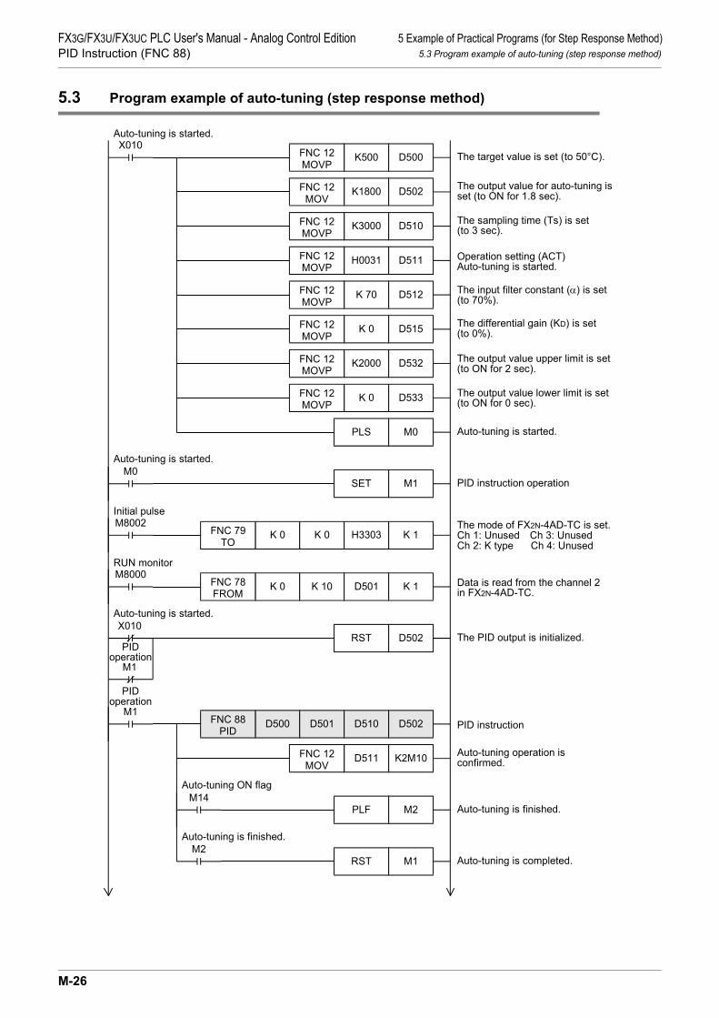
5 Example of Practical Programs (for Step Response Method)FX3G/FX3U/FX3UC PLC User's Manual - Analog Control EditionPID Instruction (FNC 88) 5.3 Program example of auto-tuning (step response method)
5.3 Program example of auto-tuning (step response method)
X010K500 D500
Auto-tuning is started.
The target value is set (to 50°C).
K1800 D502
The input filter constant (α) is set(to 70%).
K3000 D510
The output value upper limit is set(to ON for 2 sec).
H0031 D511
The output value lower limit is set(to ON for 0 sec).
K 70 D512
M0Auto-tuning is started.
PLS M0 Auto-tuning is started.
SET M1
M8002Initial pulse
K 0 K 0 H3303 K 1
M8000RUN monitor
K 0 K 10 D501 K 1
RST D502
M1
PIDoperation
D500 D501 D510 D502
The differential gain (KD) is set(to 0%).
Auto-tuning operation isconfirmed.
The sampling time (Ts) is set(to 3 sec).
Operation setting (ACT)Auto-tuning is started.
The output value for auto-tuning isset (to ON for 1.8 sec).
The mode of FX2N-4AD-TC is set.Ch 1: Unused Ch 3: UnusedCh 2: K type Ch 4: Unused
PID instruction operation
K 0 D515
K2000 D532
K 0 D533
Data is read from the channel 2in FX2N-4AD-TC.
X010Auto-tuning is started.
The PID output is initialized.
PID instruction
M1
PIDoperation
D511 K2M10
PLF M2 Auto-tuning is finished.M14
Auto-tuning ON flag
RST M1 Auto-tuning is completed.M2
Auto-tuning is finished.
FNC 12MOVP
FNC 12MOV
FNC 12MOVP
FNC 12MOVP
FNC 12MOVP
FNC 12MOVP
FNC 12MOVP
FNC 12MOVP
FNC 79TO
FNC 78FROM
FNC 88PID
FNC 12MOV
M-26

FX3G/FX3U/FX3UC PLC User's Manual - Analog Control EditionPID Instruction (FNC 88)
5 Example of Practical Programs (for Step Response Method)5.3 Program example of auto-tuning (step response method)
K
FX3U-4AD-PNK -ADP
L
FX3U-4AD-TC -ADP
M
PID Instruction (FNC 88)
M1PID operation
K2000T246
T246
T246 D502 Y021
M8067Error flag
Y020
END
Heater operation cycle timer(2 sec)
The heater operation cycle timeris preset.
Heater output
Error occurs.
RST T246
M1
PIDoperation
M1PID operation
FNC226LD <
M-27

6 TroubleshootingFX3G/FX3U/FX3UC PLC User's Manual - Analog Control EditionPID Instruction (FNC 88) 6.1 Error Codes
6. Troubleshooting
6.1 Error Codes
When an error occurs in the set value of a control parameter or the data acquired during the PID operation,the operation error flag M8067 turns ON, and a corresponding error code is stored in D8067.
Error code Error description Action
6730 Incorrect sampling time (TS) (TS ≤ 0)
<PID operation is stopped.>A data error has occurred in the set value in a control parameter or in the middle of PID operation.Check the parameters.
6732 Incorrect input filter constant (α)(α < 0 or 100 ≤ α)
6733 Incorrect proportional gain (KP) (KP < 0)
6734 Incorrect integral time (TI) (TI < 0)
6735 Incorrect derivative gain (KD)(KD < 0 or 201 ≤ KD)
6736 Incorrect derivative time (TD) (TD < 0)
6740 Sampling time (TS) ≤ Operation cycle<Auto-tuning is continued.>The operation is continued in the condition "sampling time (TS) = cyclic time (operation cycle)."
6742 Variation of measured value exceeds limit.( PV < −32768 or +32767 < PV)
<PID operation is continued.>The operation is continued with each parameter set to the maximum or minimum value.
6743 Deviation exceeds limit.(EV < −32768 or +32767 < EV)
6744 Integral result exceeds limit.(Out of range from −32768 to +32767)
6745 Derivative value exceeds limit due to derivative gain(KD).
6746 Derivative result exceeds limit.(Out of range from −32768 to +32767)
6747 PID operation result exceeds limit.(Out of range from −32768 to +32767)
6748 PID output upper limit set value < PID output lower limitset value
<Output upper limit value and output lower limit value are exchanged for each other. → PID operation is continued.>Check whether the target settings are correct.
6749 Abnormal PID input variation alarm set value or outputvariation alarm set value (Set value < 0)
<Alarm output is not given. → PID operation is continued.>Check whether the target settings are correct.
6750 <Step response method>Improper auto-tuning result
<Auto-tuning is finished. → PID operation is started.>• The deviation at start of auto-tuning is 150 or less.• The deviation at end of auto-tuning is 1/3 or more of the
deviation at start of auto-tuning.Confirm the measured value and target value, and then execute auto-tuning again.
6751 <Step response method>Auto-tuning operation direction mismatch
<Auto-tuning is forced to finish. → PID operation does not started.>The operation direction estimated from the measured value at the start of auto-tuning was different from the actual operation direction of the output during auto-tuning.Correct the relationship among the target value, output value for auto-tuning and measured value, and then execute auto-tuning again.
M-28
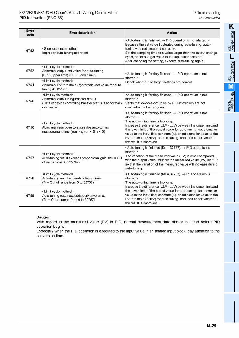
FX3G/FX3U/FX3UC PLC User's Manual - Analog Control EditionPID Instruction (FNC 88)
6 Troubleshooting6.1 Error Codes
K
FX3U-4AD-PNK -ADP
L
FX3U-4AD-TC -ADP
M
PID Instruction (FNC 88)
CautionWith regard to the measured value (PV) in PID, normal measurement data should be read before PIDoperation begins.Especially when the PID operation is executed to the input value in an analog input block, pay attention to theconversion time.
6752 <Step response method>Improper auto-tuning operation
<Auto-tuning is finished. → PID operation is not started.>Because the set value fluctuated during auto-tuning, auto-tuning was not executed correctly.Set the sampling time to a value larger than the output change cycle, or set a larger value to the input filter constant.After changing the setting, execute auto-tuning again.
6753<Limit cycle method>Abnormal output set value for auto-tuning[ULV (upper limit) ≤ LLV (lower limit)] <Auto-tuning is forcibly finished. → PID operation is not
started.>Check whether the target settings are correct.
6754<Limit cycle method>Abnormal PV threshold (hysteresis) set value for auto-tuning (SHPV < 0)
6755
<Limit cycle method>Abnormal auto-tuning transfer status(Data of device controlling transfer status is abnormally overwritten.)
<Auto-tuning is forcibly finished. → PID operation is not started.>Verify that devices occupied by PID instruction are not overwritten in the program.
6756<Limit cycle method>Abnormal result due to excessive auto-tuning measurement time (τon > τ, τon < 0, τ < 0)
<Auto-tuning is forcibly finished. → PID operation is not started.>The auto-tuning time is too long.Increase the difference (ULV - LLV) between the upper limit and the lower limit of the output value for auto-tuning, set a smaller value to the input filter constant (α), or set a smaller value to the PV threshold (SHPV) for auto-tuning, and then check whether the result is improved.
6757<Limit cycle method>Auto-tuning result exceeds proportional gain. (KP = Out of range from 0 to 32767)
<Auto-tuning is finished (KP = 32767). → PID operation is started.>The variation of the measured value (PV) is small compared with the output value. Multiply the measured value (PV) by "10" so that the variation of the measured value will increase during auto-tuning.
6758<Limit cycle method>Auto-tuning result exceeds integral time.(TI = Out of range from 0 to 32767)
<Auto-tuning is finished (KP = 32767). → PID operation is started.>The auto-tuning time is too long.Increase the difference (ULV - LLV) between the upper limit and the lower limit of the output value for auto-tuning, set a smaller value to the input filter constant (α), or set a smaller value to the PV threshold (SHPV) for auto-tuning, and then check whether the result is improved.
6759<Limit cycle method>Auto-tuning result exceeds derivative time.(TD = Out of range from 0 to 32767)
Error code Error description Action
M-29

6 TroubleshootingFX3G/FX3U/FX3UC PLC User's Manual - Analog Control EditionPID Instruction (FNC 88) 6.1 Error Codes
MEMO
M-30

WarrantyFX3G/FX3U/FX3UC PLC User's Manual - Analog Control Edition
WarrantyPlease confirm the following product warranty details before using this product.
1. Gratis Warranty Term and Gratis Warranty Range If any faults or defects (hereinafter "Failure") found to bethe responsibility of Mitsubishi occurs during use of theproduct within the gratis warranty term, the product shall berepaired at no cost via the sales representative orMitsubishi Service Company. However, if repairs arerequired onsite at domestic or overseas location, expensesto send an engineer will be solely at the customer'sdiscretion. Mitsubishi shall not be held responsible for anyre-commissioning, maintenance, or testing on-site thatinvolves replacement of the failed module.
[Gratis Warranty Term] The gratis warranty term of the product shall be for oneyear after the date of purchase or delivery to a designatedplace. Note that after manufacture and shipment fromMitsubishi, the maximum distribution period shall be six (6)months, and the longest gratis warranty term aftermanufacturing shall be eighteen (18) months. The gratiswarranty term of repair parts shall not exceed the gratiswarranty term before repairs.
[Gratis Warranty Range] 1) The range shall be limited to normal use within the
usage state, usage methods and usage environment,etc., which follow the conditions and precautions, etc.,given in the instruction manual, user's manual andcaution labels on the product.
2) Even within the gratis warranty term, repairs shall becharged for in the following cases. a) Failure occurring from inappropriate storage or
handling, carelessness or negligence by the user.Failure caused by the user's hardware or softwaredesign.
b) Failure caused by unapproved modifications, etc.,to the product by the user.
c) When the Mitsubishi product is assembled into auser's device, Failure that could have beenavoided if functions or structures, judged asnecessary in the legal safety measures the user'sdevice is subject to or as necessary by industrystandards, had been provided.
d) Failure that could have been avoided ifconsumable parts (battery, backlight, fuse, etc.)designated in the instruction manual had beencorrectly serviced or replaced.
e) Relay failure or output contact failure caused byusage beyond the specified Life of contact(cycles).
f) Failure caused by external irresistible forces suchas fires or abnormal voltages, and failure causedby force majeure such as earthquakes, lightning,wind and water damage.
g) Failure caused by reasons unpredictable byscienti f ic technology standards at t ime ofshipment from Mitsubishi.
h) Any other failure found not to be the responsibilityof Mitsubishi or that admitted not to be so by theuser.
2. Onerous repair term after discontinuation of production 1) Mitsubishi shall accept onerous product repairs for
seven (7) years after production of the product isdiscontinued.Discontinuation of production shall be notified withMitsubishi Technical Bulletins, etc.
2) Product supply (including repair parts) is not availableafter production is discontinued.
3. Overseas service Overseas, repairs shall be accepted by Mitsubishi's localoverseas FA Center. Note that the repair conditions ateach FA Center may differ.
4. Exclusion of loss in opportunity and secondary loss from warranty liability Regardless of the gratis warranty term, Mitsubishi shall notbe liable for compensation of damages caused by anycause found not to be the responsibility of Mitsubishi, lossin opportunity, lost profits incurred to the user or thirdperson by Failures of Mitsubishi products, specialdamages and secondary damages whether foreseeable ornot , compensation for accidents, and compensation fordamages to products other than Mitsubishi products,replacement by the user, maintenance of on-siteequipment, start-up test run and other tasks.
5. Changes in product specifications The specifications given in the catalogs, manuals ortechnical documents are subject to change without priornotice.
6. Product application 1) In using the Mitsubishi MELSEC programmable logic
controller, the usage conditions shall be that theapplication will not lead to a major accident even if anyproblem or fault should occur in the programmablelogic controller device, and that backup and fail-safefunctions are systematically provided outside of thedevice for any problem or fault.
2) The Mitsubishi programmable logic controller hasbeen designed and manufactured for applications ingeneral industries, etc. Thus, applications in which thepublic could be affected such as in nuclear powerplants and other power plants operated by respectivepower companies, and applications in which a specialquality assurance system is required, such as forRailway companies or Public service purposes shallbe excluded from the programmable logic controllerapplications. In addition, applications in which human life orproperty that could be greatly affected, such as inaircraft, medical applications, incineration and fueldevices, manned transportation, equipment forrecreation and amusement, and safety devices, shallalso be excluded from the programmable logiccontroller range of applications. However, in certain cases, some applications may bepossible, providing the user consults their localMitsubishi representative outlining the specialrequirements of the project, and providing that allparties concerned agree to the special circumstances,solely at the users discretion.
i
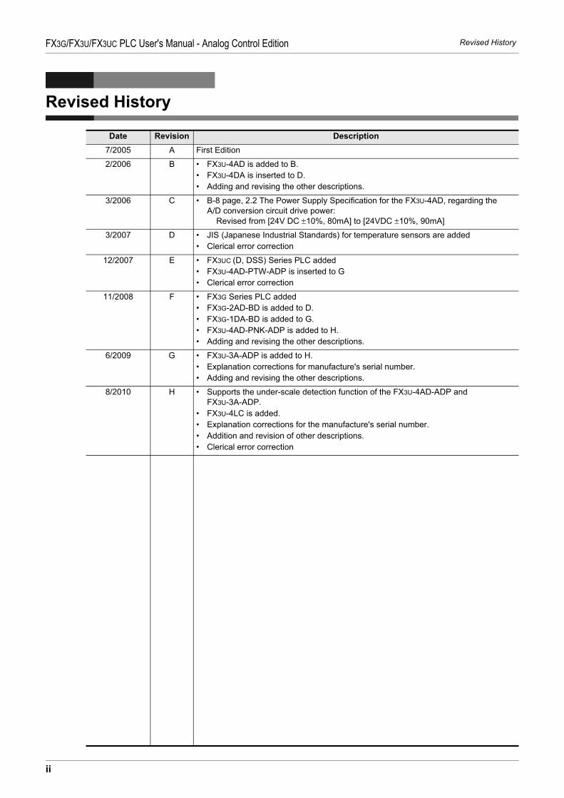
Revised HistoryFX3G/FX3U/FX3UC PLC User's Manual - Analog Control Edition
Revised History
Date Revision Description7/2005 A First Edition
2/2006 B • FX3U-4AD is added to B.• FX3U-4DA is inserted to D.• Adding and revising the other descriptions.
3/2006 C • B-8 page, 2.2 The Power Supply Specification for the FX3U-4AD, regarding the A/D conversion circuit drive power: Revised from [24V DC ±10%, 80mA] to [24VDC ±10%, 90mA]
3/2007 D • JIS (Japanese Industrial Standards) for temperature sensors are added• Clerical error correction
12/2007 E • FX3UC (D, DSS) Series PLC added• FX3U-4AD-PTW-ADP is inserted to G• Clerical error correction
11/2008 F • FX3G Series PLC added• FX3G-2AD-BD is added to D.• FX3G-1DA-BD is added to G.• FX3U-4AD-PNK-ADP is added to H.• Adding and revising the other descriptions.
6/2009 G • FX3U-3A-ADP is added to H.• Explanation corrections for manufacture's serial number.• Adding and revising the other descriptions.
8/2010 H • Supports the under-scale detection function of the FX3U-4AD-ADP and FX3U-3A-ADP.
• FX3U-4LC is added.• Explanation corrections for the manufacture's serial number.• Addition and revision of other descriptions.• Clerical error correction
ii

HEAD OFFICE: TOKYO BUILDING, 2-7-3 MARUNOUCHI, CHIYODA-KU, TOKYO 100-8310, JAPANHIMEJI WORKS: 840, CHIYODA CHO, HIMEJI, JAPAN
JY997D16701H(MEE)
Effective August 2010Specifications are subject to change without notice.
MODEL FX3U-U-ANALOG-E
MODEL CODE 09R619
FX3G/FX3U/FX3UC SERIES PROGRAMMABLE CONTROLLERS
Analog Control Edition
USER'S MANUAL

HEADQUARTERS
EUROPEMITSUBISHI ELECTRIC EUROPE B.V.German BranchGothaer Straße 8D-40880 RatingenPhone: +49 (0)2102 / 486-0Fax: +49 (0)2102 / 486-1120
CZECH REPUBLICMITSUBISHI ELECTRIC EUROPE B.V.Czech BranchAvenir Business Park, Radlická 714/113aCZ-158 00 Praha 5Phone: +420 - 251 551 470Fax: +420 - 251-551-471
FRANCEMITSUBISHI ELECTRIC EUROPE B.V.French Branch25, Boulevard des BouvetsF-92741 Nanterre CedexPhone: +33 (0)1 / 55 68 55 68Fax: +33 (0)1 / 55 68 57 57
IRELANDMITSUBISHI ELECTRIC EUROPE B.V.Irish BranchWestgate Business Park, BallymountIRL-Dublin 24Phone: +353 (0)1 4198800Fax: +353 (0)1 4198890
ITALYMITSUBISHI ELECTRIC EUROPE B.V.Italian BranchViale Colleoni 7I-20041 Agrate Brianza (MB)Phone: +39 039 / 60 53 1Fax: +39 039 / 60 53 312
POLANDMITSUBISHI ELECTRIC EUROPE B.V.Poland BranchKrakowska 50PL-32-083 BalicePhone: +48 (0)12 / 630 47 00Fax: +48 (0)12 / 630 47 01
SPAINMITSUBISHI ELECTRIC EUROPE B.V.Spanish BranchCarretera de Rubí 76-80E-08190 Sant Cugat del Vallés (Barcelona)Phone: 902 131121 // +34 935653131Fax: +34 935891579
UKMITSUBISHI ELECTRIC EUROPE B.V.UK BranchTravellers LaneUK-Hatfield, Herts. AL10 8XBPhone: +44 (0)1707 / 27 61 00Fax: +44 (0)1707 / 27 86 95
JAPANMITSUBISHI ELECTRIC CORPORATIONOffice Tower “Z” 14 F8-12,1 chome, Harumi Chuo-KuTokyo 104-6212Phone: +81 3 622 160 60Fax: +81 3 622 160 75
USAMITSUBISHI ELECTRIC AUTOMATION, Inc.500 Corporate Woods ParkwayVernon Hills, IL 60061Phone: +1 847 478 21 00Fax: +1 847 478 22 53
EUROPEAN REPRESENTATIVES
AUSTRIAGEVAWiener Straße 89AT-2500 BadenPhone: +43 (0)2252 / 85 55 20Fax: +43 (0)2252 / 488 60
BELARUSTEHNIKONOktyabrskaya 16/5, Off. 703-711BY-220030 MinskPhone: +375 (0)17 / 210 46 26Fax: +375 (0)17 / 210 46 26
BELGIUMESCO DRIVES & AUTOMATIONCulliganlaan 3BE-1831 DiegemPhone: +32 (0)2 / 717 64 30Fax: +32 (0)2 / 717 64 31
BELGIUMKoning & Hartman b.v.Woluwelaan 31BE-1800 VilvoordePhone: +32 (0)2 / 257 02 40Fax: +32 (0)2 / 257 02 49
BOSNIA AND HERZEGOVINAINEA BH d.o.o.Aleja Lipa 56BA-71000 SarajevoPhone: +387 (0)33 / 921 164Fax: +387 (0)33/ 524 539
BULGARIAAKHNATON4 Andrej Ljapchev Blvd. Pb 21BG-1756 SofiaPhone: +359 (0)2 / 817 6004Fax: +359 (0)2 / 97 44 06 1
CROATIAINEA CR d.o.o.Losinjska 4 aHR-10000 ZagrebPhone: +385 (0)1 / 36 940 - 01/ -02/ -03Fax: +385 (0)1 / 36 940 - 03
CZECH REPUBLICAutoCont C.S. s.r.o.Technologická 374/6CZ-708 00 Ostrava-PustkovecPhone: +420 595 691 150Fax: +420 595 691 199
CZECH REPUBLICB:ELECTRIC, s.r.o.Mladoboleslavská 812CZ-197 00 Praha 19 - KbelyPhone: +420 286 850 848, +420 724 317 975Fax: +420 286 850 850
DENMARKBeijer Electronics A/SLykkegårdsvej 17DK-4000 RoskildePhone: +45 (0)46/ 75 76 66Fax: +45 (0)46 / 75 56 26
ESTONIABeijer Electronics Eesti OÜPärnu mnt.160iEE-11317 TallinnPhone: +372 (0)6 / 51 81 40Fax: +372 (0)6 / 51 81 49
FINLANDBeijer Electronics OYPeltoie 37FIN-28400 UlvilaPhone: +358 (0)207 / 463 540Fax: +358 (0)207 / 463 541
GREECEUTECO A.B.E.E.5, Mavrogenous Str.GR-18542 PiraeusPhone: +30 211 / 1206 900Fax: +30 211 / 1206 999
HUNGARYMELTRADE Kft.Fertő utca 14.HU-1107 BudapestPhone: +36 (0)1 / 431-9726Fax: +36 (0)1 / 431-9727
LATVIABeijer Electronics SIARitausmas iela 23LV-1058 RigaPhone: +371 (0)784 / 2280Fax: +371 (0)784 / 2281
LITHUANIABeijer Electronics UABSavanoriu Pr. 187LT-02300 VilniusPhone: +370 (0)5 / 232 3101Fax: +370 (0)5 / 232 2980
EUROPEAN REPRESENTATIVES
MALTAALFATRADE Ltd.99, Paola HillMalta- Paola PLA 1702Phone: +356 (0)21 / 697 816Fax: +356 (0)21 / 697 817
MOLDOVAINTEHSIS srlbld. Traian 23/1MD-2060 KishinevPhone: +373 (0)22 / 66 4242Fax: +373 (0)22 / 66 4280
NETHERLANDSHIFLEX AUTOM.TECHNIEK B.V.Wolweverstraat 22NL-2984 CD RidderkerkPhone: +31 (0)180 – 46 60 04Fax: +31 (0)180 – 44 23 55
NETHERLANDSKoning & Hartman b.v.Haarlerbergweg 21-23NL-1101 CH AmsterdamPhone: +31 (0)20 / 587 76 00Fax: +31 (0)20 / 587 76 05
NORWAYBeijer Electronics ASPostboks 487NO-3002 DrammenPhone: +47 (0)32 / 24 30 00Fax: +47 (0)32 / 84 85 77
ROMANIASirius Trading & Services srlAleea Lacul Morii Nr. 3RO-060841 Bucuresti, Sector 6Phone: +40 (0)21 / 430 40 06Fax: +40 (0)21 / 430 40 02
SERBIACraft Con. & Engineering d.o.o.Bulevar Svetog Cara Konstantina 80-86SER-18106 NisPhone: +381 (0)18 / 292-24-4/5Fax: +381 (0)18 / 292-24-4/5
SERBIAINEA SR d.o.o.Izletnicka 10SER-113000 SmederevoPhone: +381 (0)26 / 617 163Fax: +381 (0)26 / 617 163
SLOVAKIAAutoCont Control s.r.o.Radlinského 47SK-02601 Dolny KubinPhone: +421 (0)43 / 5868210Fax: +421 (0)43 / 5868210
SLOVAKIACS MTrade Slovensko, s.r.o.Vajanskeho 58SK-92101 PiestanyPhone: +421 (0)33 / 7742 760Fax: +421 (0)33 / 7735 144
SLOVENIAINEA d.o.o.Stegne 11SI-1000 LjubljanaPhone: +386 (0)1 / 513 8100Fax: +386 (0)1 / 513 8170
SWEDENBeijer Electronics ABBox 426SE-20124 MalmöPhone: +46 (0)40 / 35 86 00Fax: +46 (0)40 / 93 23 01
SWITZERLANDOmni Ray AGIm Schörli 5CH-8600 DübendorfPhone: +41 (0)44 / 802 28 80Fax: +41 (0)44 / 802 28 28
TURKEYGTSBayraktar Bulvari Nutuk Sok. No:5TR-34775 Yukarı Dudullu-Ümraniye-İSTANBULPhone: +90 (0)216 526 39 90Fax: +90 (0)216 526 3995
UKRAINECSC Automation Ltd.4-B, M. Raskovoyi St.UA-02660 KievPhone: +380 (0)44 / 494 33 55Fax: +380 (0)44 / 494-33-66
EURASIAN REPRESENTATIVES
KAZAKHSTANKazpromautomatics Ltd.Mustafina Str. 7/2KAZ-470046 KaragandaPhone: +7 7212 / 50 11 50Fax: +7 7212 / 50 11 50
MIDDLE EAST REPRESENTATIVES
ISRAELTEXEL ELECTRONICS Ltd.2 Ha´umanut, P.O.B. 6272IL-42160 NetanyaPhone: +972 (0)9 / 863 39 80Fax: +972 (0)9 / 885 24 30
LEBANONCEG INTERNATIONALCebaco Center/Block A Autostrade DORALebanon - BeirutPhone: +961 (0)1 / 240 430Fax: +961 (0)1 / 240 438
AFRICAN REPRESENTATIVE
SOUTH AFRICACBI Ltd.Private Bag 2016ZA-1600 IsandoPhone: + 27 (0)11 / 977 0770Fax: + 27 (0)11 / 977 0761
Mitsubishi Electric Europe B.V. /// FA - European Business Group /// Gothaer Straße 8 /// D-40880 Ratingen /// GermanyTel.: +49(0)2102-4860 /// Fax: +49(0)2102-4861120 /// [email protected] /// www.mitsubishi-automation.com
MITSUBISHI ELECTRIC