prof. z ghassemlooy1 en554 photonic networks professor z ghassemlooy lecture 2 - devices &...
Post on 21-Dec-2015
228 views
TRANSCRIPT
1Prof. Z Ghassemlooy
EN554 Photonic Networks
Professor Z Ghassemlooy
Lecture 2 - Devices & Components
Northumbria Communications LaboratorySchool of Informatics, Engineering and
TechnologyThe University of Northumbria
U.K.http://soe.unn.ac.uk/ocr
2Prof. Z Ghassemlooy
Contents
Connectors + Optical Splice Attenuators Coupler Splitter Filters Fibre Brag Grating Optical Isolator Circulators Optical Add/Drop Multiplexer & Demultiplexer
3Prof. Z Ghassemlooy
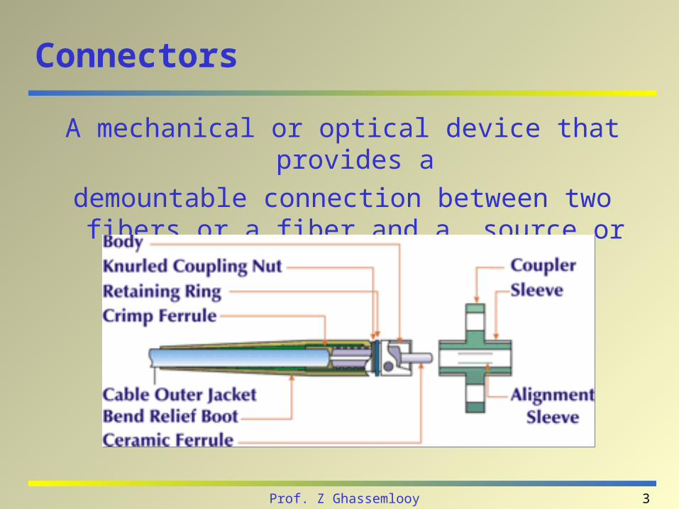
Connectors
A mechanical or optical device that provides a
demountable connection between two fibers or a fiber and a source or detector.
4Prof. Z Ghassemlooy
Connectors - contd.
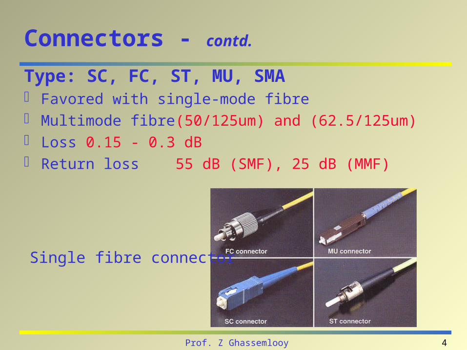
Type: SC, FC, ST, MU, SMA Favored with single-mode fibre Multimode fibre (50/125um) and (62.5/125um) Loss 0.15 - 0.3 dB Return loss 55 dB (SMF), 25 dB (MMF)
Single fibre connector
5Prof. Z Ghassemlooy
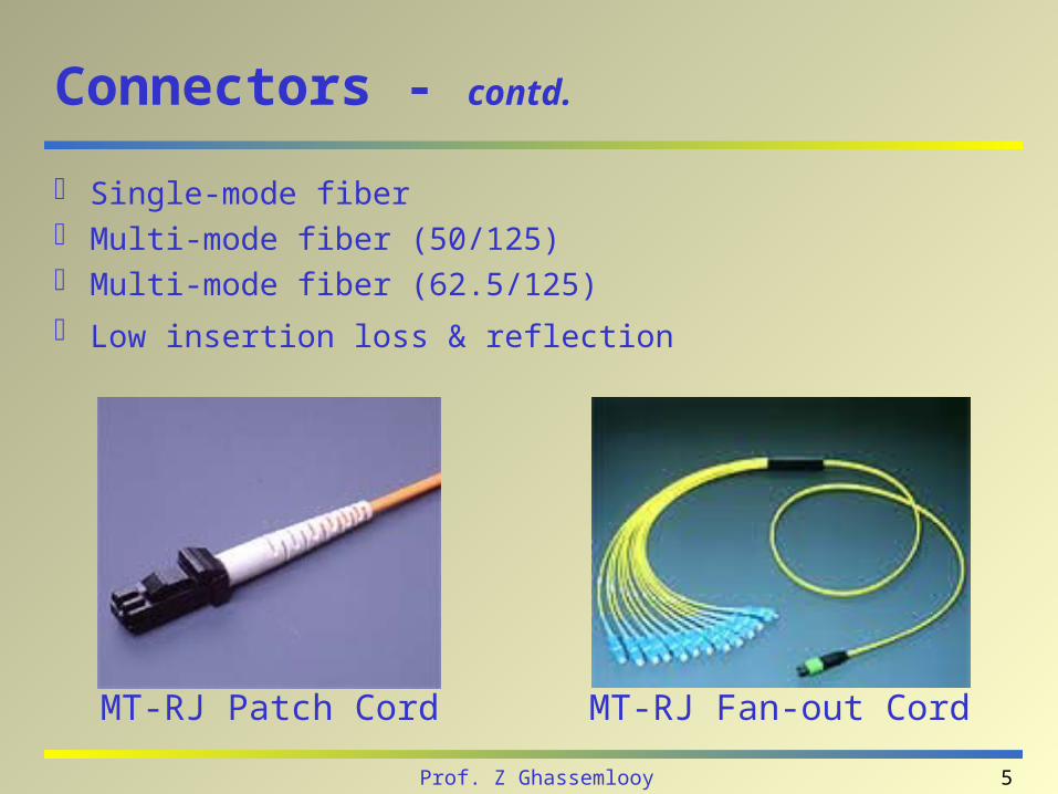
Connectors - contd.
Single-mode fiber Multi-mode fiber (50/125) Multi-mode fiber (62.5/125)
Low insertion loss & reflection
MT-RJ Patch Cord MT-RJ Fan-out Cord
6Prof. Z Ghassemlooy
Optical Splices
Mechanical – Ends of two pieces of fiber are cleaned and stripped, then carefully butted
together and aligned using a mechanical assembly. A gel is used at the point of contact to reduce light reflection and keep the splice loss at a minimum. The ends of the fiber are held together by friction or compression, and the splice assembly features a locking mechanism so
that the fibers remained aligned.
Fusion– Involves actually melting (fusing) together the ends of two pieces of
fiber. The result is a continuous fiber without a break.
Both are capable of splice losses in the range of 0.15 dB (3%) to
0.1 dB (2%).
7Prof. Z Ghassemlooy
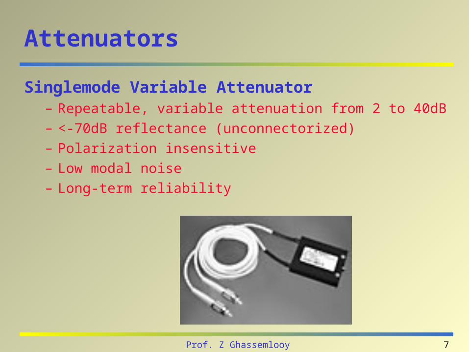
Attenuators
Singlemode Variable Attenuator– Repeatable, variable attenuation from 2 to 40dB
– <-70dB reflectance (unconnectorized)
– Polarization insensitive
– Low modal noise
– Long-term reliability
8Prof. Z Ghassemlooy
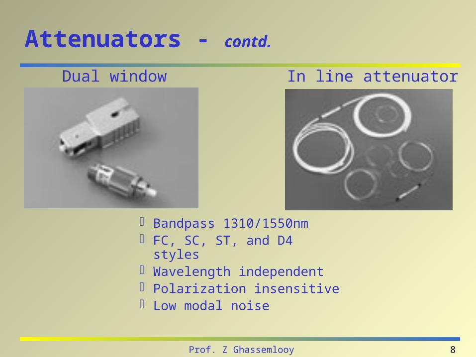
Attenuators - contd.
Bandpass 1310/1550nm FC, SC, ST, and D4 styles Wavelength independent Polarization insensitive Low modal noise
In line attenuatorDual window

9Prof. Z Ghassemlooy
Optical Couplers
Optic couplers either split optical signals into multiple paths or combine multiple signals on one path.
The number of input (N)/ output (M) ports, (i.e.s N x M size) characterizes a coupler.
Fused couplers can be made in any configuration, but they commonly use multiples of two (2 x 2, 4 x 4, 8 x 8, etc.).
10Prof. Z Ghassemlooy
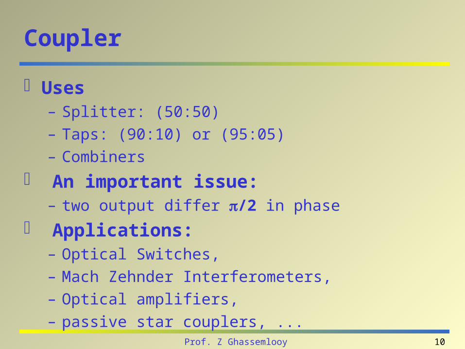
Coupler
Uses– Splitter: (50:50)– Taps: (90:10) or (95:05)– Combiners
An important issue: – two output differ /2 in phase
Applications: – Optical Switches, – Mach Zehnder Interferometers, – Optical amplifiers, – passive star couplers, ...
11Prof. Z Ghassemlooy
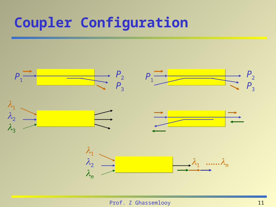
Coupler Configuration
P1P2
P3
P1P2
P3
1
2
3
1
2
n
1 ……n
12Prof. Z Ghassemlooy
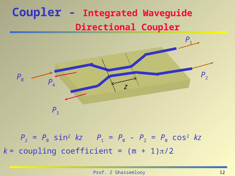
Coupler - Integrated Waveguide
Directional Coupler
P2 = P0 sin2 kz P1 = P0 - P2 = P0 cos2 kz
k = coupling coefficient = (m + 1)/2
P0
P1
P2
P3
zP4
13Prof. Z Ghassemlooy
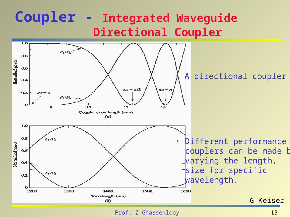
Coupler - Integrated Waveguide Directional Coupler
• A directional coupler
• Different performance couplers can be made by varying the length, size for specific wavelength.
G Keiser
14Prof. Z Ghassemlooy
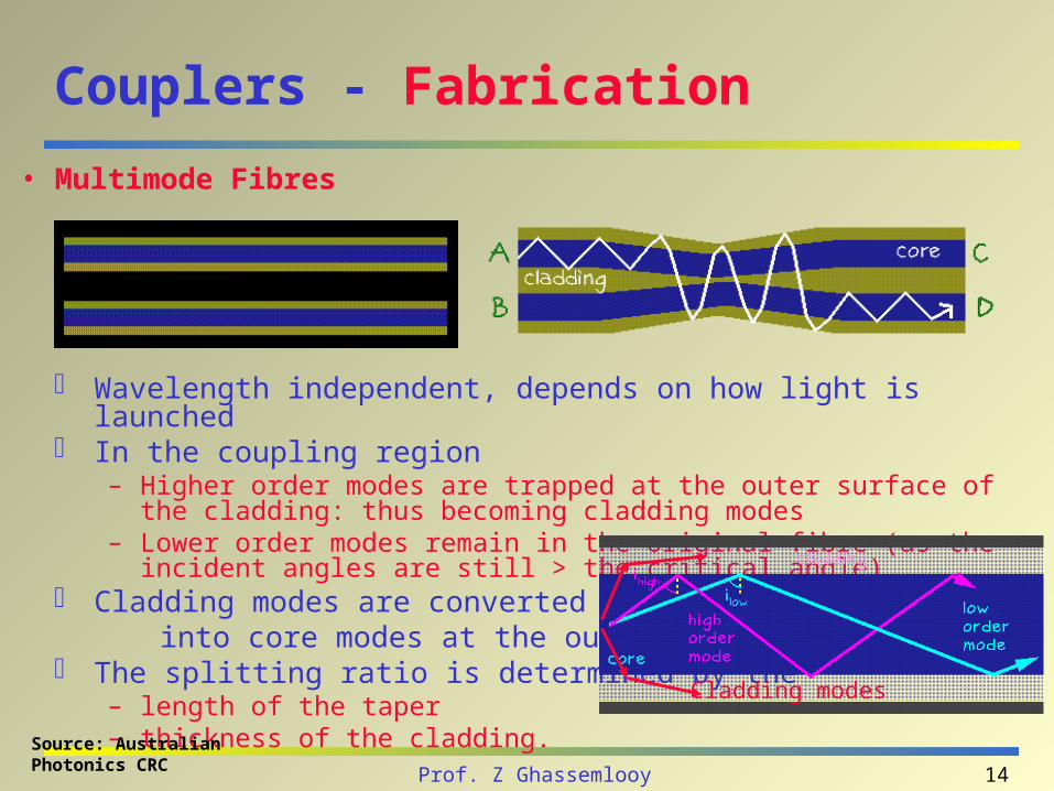
Couplers - Fabrication
Wavelength independent, depends on how light is launched In the coupling region
– Higher order modes are trapped at the outer surface of the cladding: thus becoming cladding modes
– Lower order modes remain in the original fibre (as the incident angles are still > the critical angle)
Cladding modes are converted back into core modes at the output ports. The splitting ratio is determined by the
– length of the taper – thickness of the cladding.
• Multimode Fibres
Cladding modes
Source: Australian Photonics CRC
15Prof. Z Ghassemlooy
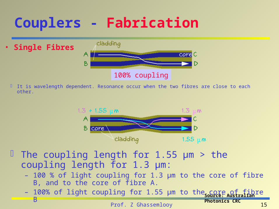
Couplers - Fabrication
It is wavelength dependent. Resonance occur when the two fibres are close to each other.
• Single Fibres
100% coupling
The coupling length for 1.55 µm > the coupling length for 1.3 µm: – 100 % of light coupling for 1.3 µm to the core of fibre B, and to the core of
fibre A. – 100% of light coupling for 1.55 µm to the core of fibre B
Source: Australian Photonics CRC
16Prof. Z Ghassemlooy
Couplers - Fabrication
The amount of power transmitted into fibres depend on the coupling length
The coupling length changes with the wavelength. The splitting ratio can be tuned choosing the coupling
length. By choosing carefully the coupler length, it is possible to
combine or separate Two different wavelengths
17Prof. Z Ghassemlooy
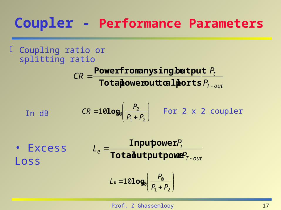
Coupler - Performance Parameters
Coupling ratio or splitting ratio
outT
t
P
PCR
portsalltooutpowerTotal
outputsingleanyfromPower
• Excess LossoutT
ie P
PL
routputpoweTotal
powerInput
21
01010
PP
PLe log
21
21010
PP
PCR logIn dB For 2 x 2 coupler
18Prof. Z Ghassemlooy
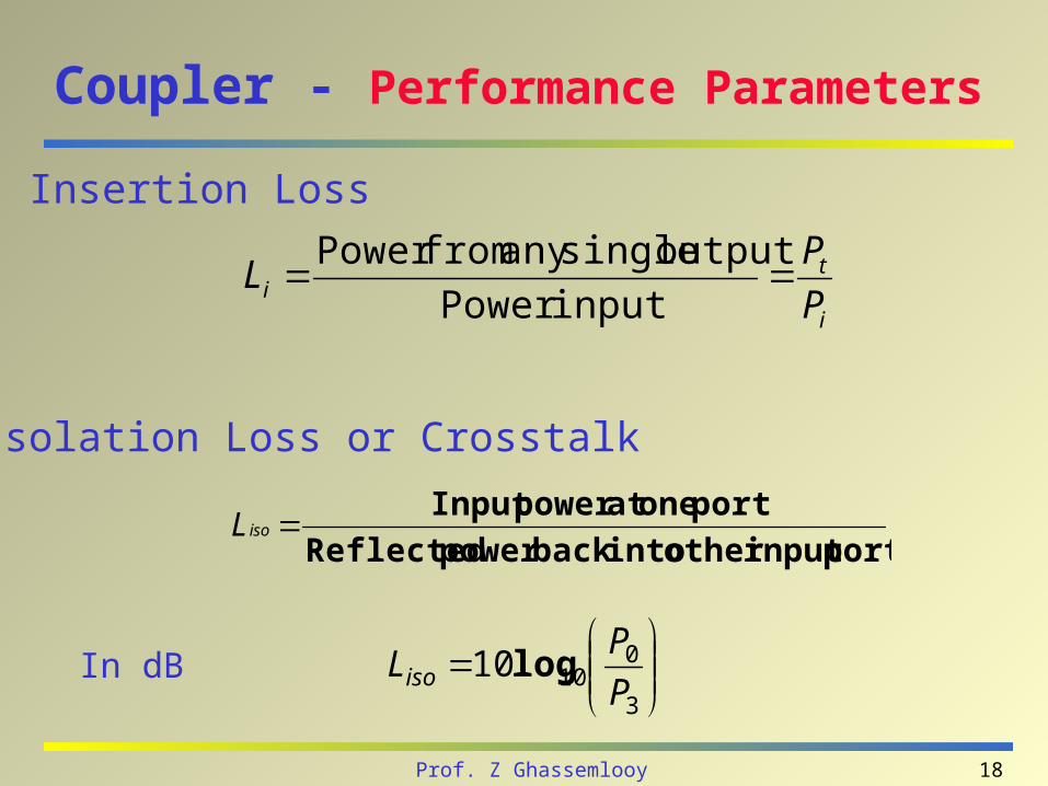
Coupler - Performance Parameters
• Isolation Loss or Crosstalk
• Insertion Loss
i
ti P
PL
inputPower
outputsingleanyfromPower
3
01010
P
PLiso log
portinputotherintobackpowerReflected
portoneatpowerInputisoL
In dB
19Prof. Z Ghassemlooy
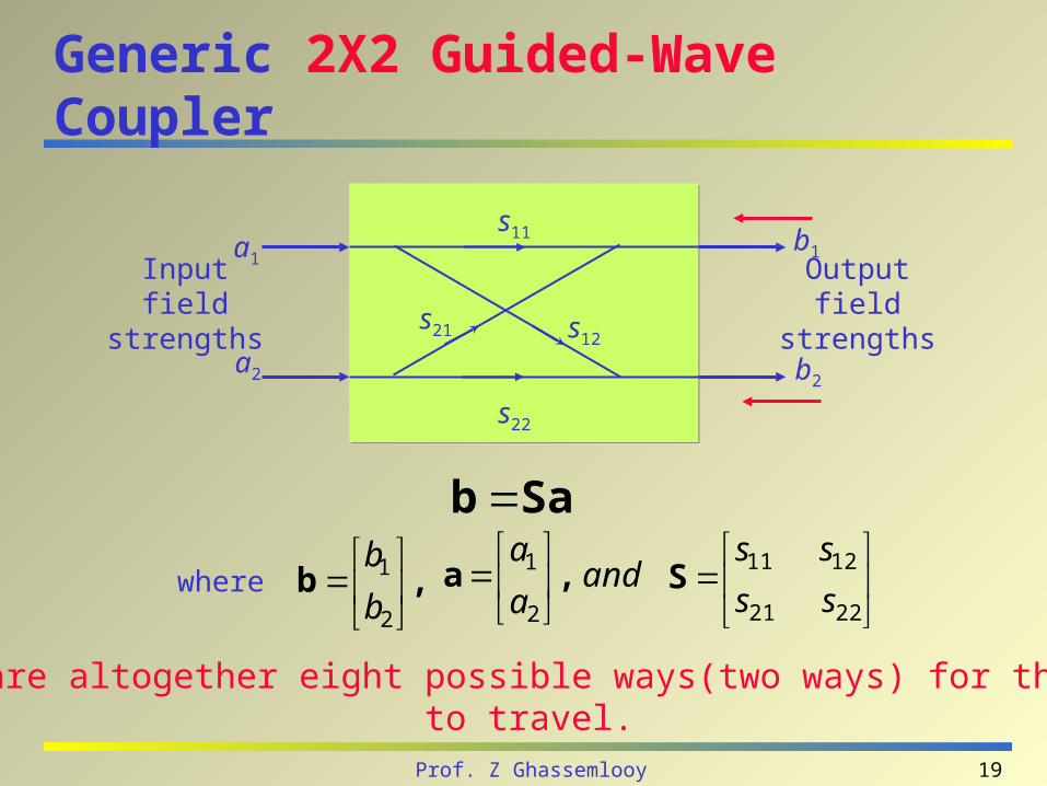
Generic 2X2 Guided-Wave Coupler
Sab
,b
2
1
b
band
a
a,a
2
1
2221
1211
ss
ssSwhere
There are altogether eight possible ways(two ways) for the light to travel.
a1
a2
b1
b2
Inputfield
strengths
Outputfield
strengths
s22
s21 s12
s11
20Prof. Z Ghassemlooy
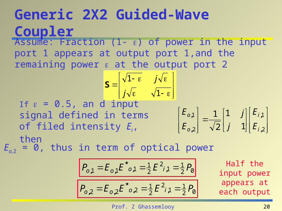
Generic 2X2 Guided-Wave Coupler
Assume: Fraction (1- ) of power in the input port 1 appears at output port 1,and the remaining power at the output port 2
1
1
j
jS
If = 0.5, an d input signal defined in terms of filed intensity Ei, then
2
1
2
1
1
1
2
1
,
,
,
,
i
i
o
o
E
E
j
j
E
E
Let Eo,2 = 0, thus in term of optical power
021
12
21
111 PEEEP iooo ,,*
,,
021
12
21
222 PEEEP iooo ,,*
,,
Half the input power appears at
each output
21Prof. Z Ghassemlooy
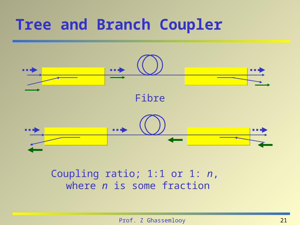
Tree and Branch Coupler
Coupling ratio; 1:1 or 1: n, where n is some fraction
Fibre
22Prof. Z Ghassemlooy
Star Couplers
Optical couplers with more than four ports. Types of star couplers:
– transmission star coupler the light at any of the input port is split equally through all output ports.
– reflection star coupler
23Prof. Z Ghassemlooy
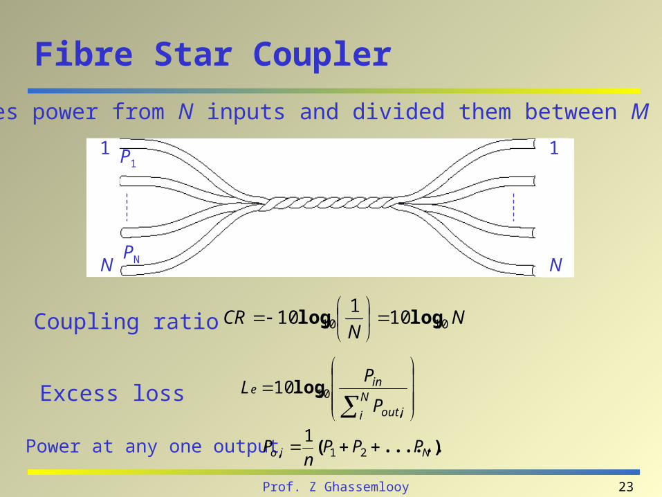
Fibre Star Coupler
Combines power from N inputs and divided them between M outputs
NN
CR 1010 101
10 loglog
Coupling ratio
N
i iout
ine
P
PL
,
log1010Excess loss
1
N
1
N
P1
PN
Power at any one output ).......(, Nio PPPn
P 211

24Prof. Z Ghassemlooy
Star Coupler - 8 X 8
1
2
3
4
5
6
7
8
1, 2, ... 8
1, 2, ... 8
No of 3 dB coupler NN
N dBc 23 2log
N/2
N2log
Star couplers are optical couplers with more than four ports
25Prof. Z Ghassemlooy
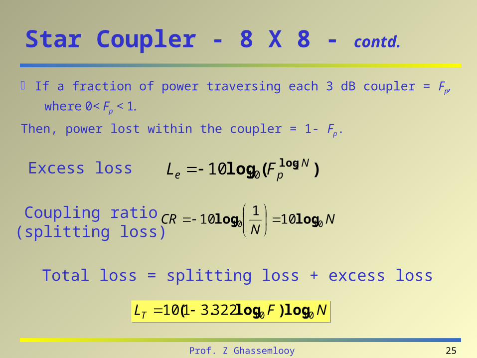
Star Coupler - 8 X 8 - contd.
If a fraction of power traversing each 3 dB coupler = Fp,
where 0< Fp < 1.
Then, power lost within the coupler = 1- Fp.
Excess loss )(log log Npe FL 2
1010
NN
CR 1010 101
10 loglog
Coupling ratio
(splitting loss)
Total loss = splitting loss + excess loss
NFLT 10103223110 log)log.( NFLT 10103223110 log)log.(
26Prof. Z Ghassemlooy
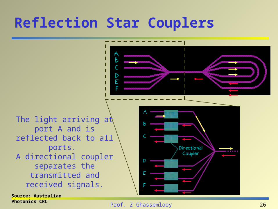
Reflection Star Couplers
The light arriving at port A and is reflected back to all
ports. A directional coupler
separates the transmitted and received signals.
Source: Australian Photonics CRC
27Prof. Z Ghassemlooy
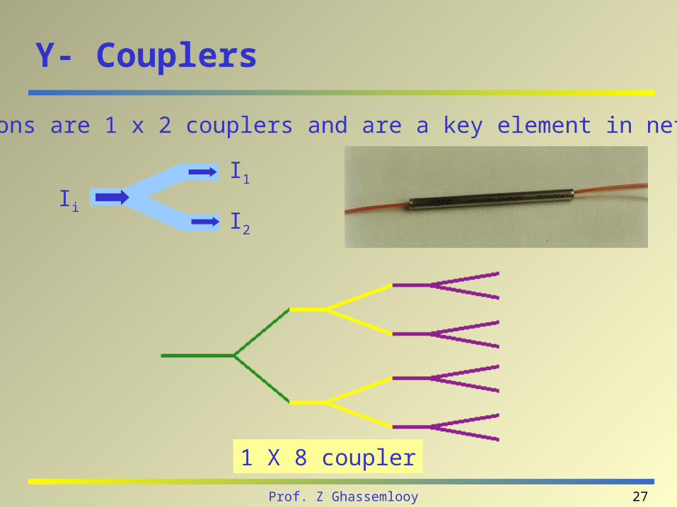
Y- Couplers
1 X 8 coupler
Y-junctions are 1 x 2 couplers and are a key element in networking.
Ii
I1
I2
28Prof. Z Ghassemlooy
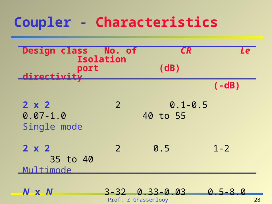
Coupler - Characteristics
Design class No. of CR Le Isolationport (dB) directivity
(-dB)
2 x 2 2 0.1-0.5 0.07-1.0 40 to 55Single mode
2 x 2 2 0.5 1-2 35 to 40Multimode
N x N 3-32 0.33-0.03 0.5-8.0Star
29Prof. Z Ghassemlooy
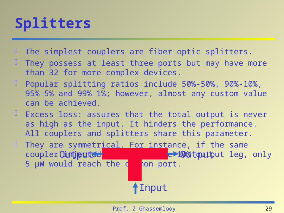
Splitters
The simplest couplers are fiber optic splitters. They possess at least three ports but may have more than 32 for more
complex devices. Popular splitting ratios include 50%-50%, 90%-10%, 95%-5% and 99%-1%;
however, almost any custom value can be achieved. Excess loss: assures that the total output is never as high as the input. It
hinders the performance. All couplers and splitters share this parameter. They are symmetrical. For instance, if the same coupler injected 50 µW into
the 10% output leg, only 5 µW would reach the common port.
OutputOutput
Input
30Prof. Z Ghassemlooy
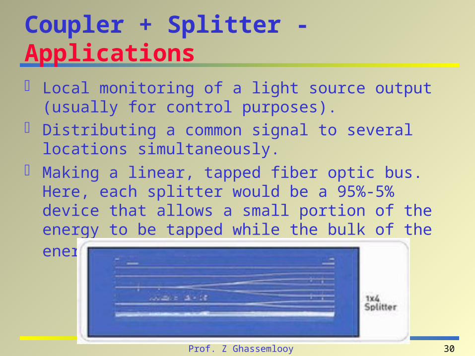
Coupler + Splitter - Applications
Local monitoring of a light source output (usually for control purposes).
Distributing a common signal to several locations simultaneously.
Making a linear, tapped fiber optic bus. Here, each splitter would be a 95%-5% device that allows a small portion of the energy to be tapped while the bulk of the energy continues down the main trunk.

31Prof. Z Ghassemlooy
Optical Filters
i-1 i i+1
PassbandCrosstalk Crosstalk
• Passband- Insertion loss- Ripple- Wavelengths (peak, center, edges)- Bandwidths (0.5 dB, 3 dB, ..)- Polarization dependence
• Stopband- Crosstalk rejection- Bandwidths - (20 dB, 40 dB, ..)
Agilent Tech. LW Div.
32Prof. Z Ghassemlooy
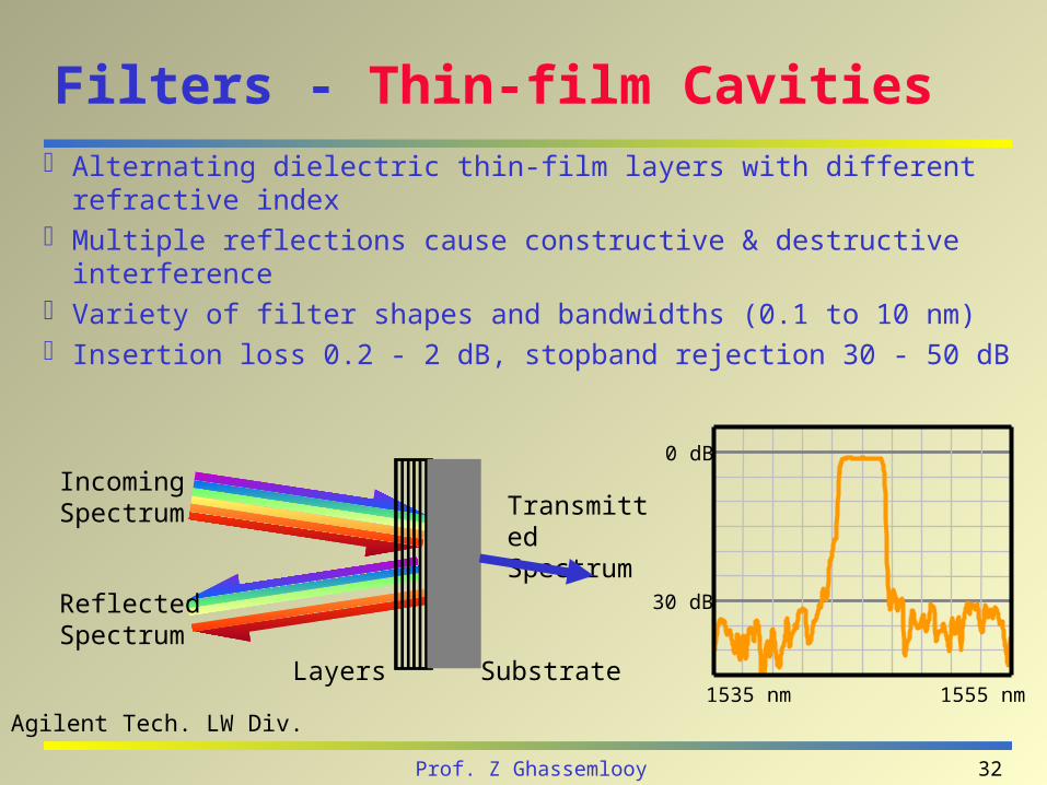
Filters - Thin-film Cavities
Alternating dielectric thin-film layers with different refractive index
Multiple reflections cause constructive & destructive interference Variety of filter shapes and bandwidths (0.1 to 10 nm) Insertion loss 0.2 - 2 dB, stopband rejection 30 - 50 dB
1535 nm 1555 nm
0 dB
30 dB
Agilent Tech. LW Div.
Layers Substrate
Incoming Spectrum
Reflected Spectrum
Transmitted Spectrum
33Prof. Z Ghassemlooy
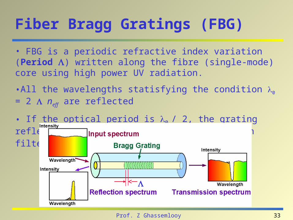
Fiber Bragg Gratings (FBG)
• FBG is a periodic refractive index variation (Period ) written along the fibre (single-mode) core using high power UV radiation.
•All the wavelengths statisfying the condition 0 = 2 neff are reflected
• If the optical period is 0 / 2, the grating reflects wavelength 0 selectively. Useful in filtering communication channels in or out.
34Prof. Z Ghassemlooy
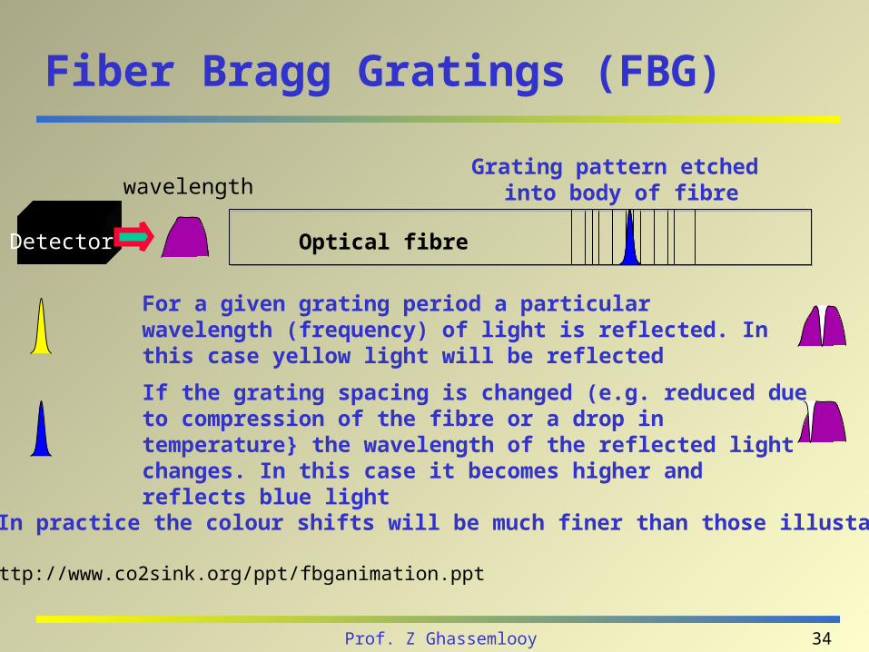
wavelength
For a given grating period a particular wavelength (frequency) of light is reflected. In this case yellow light will be reflected
If the grating spacing is changed (e.g. reduced due to compression of the fibre or a drop in temperature} the wavelength of the reflected light changes. In this case it becomes higher and reflects blue light
In practice the colour shifts will be much finer than those illustated
Optical fibre
Grating pattern etched into body of fibre
Detector
http://www.co2sink.org/ppt/fbganimation.ppt
Fiber Bragg Gratings (FBG)
35Prof. Z Ghassemlooy
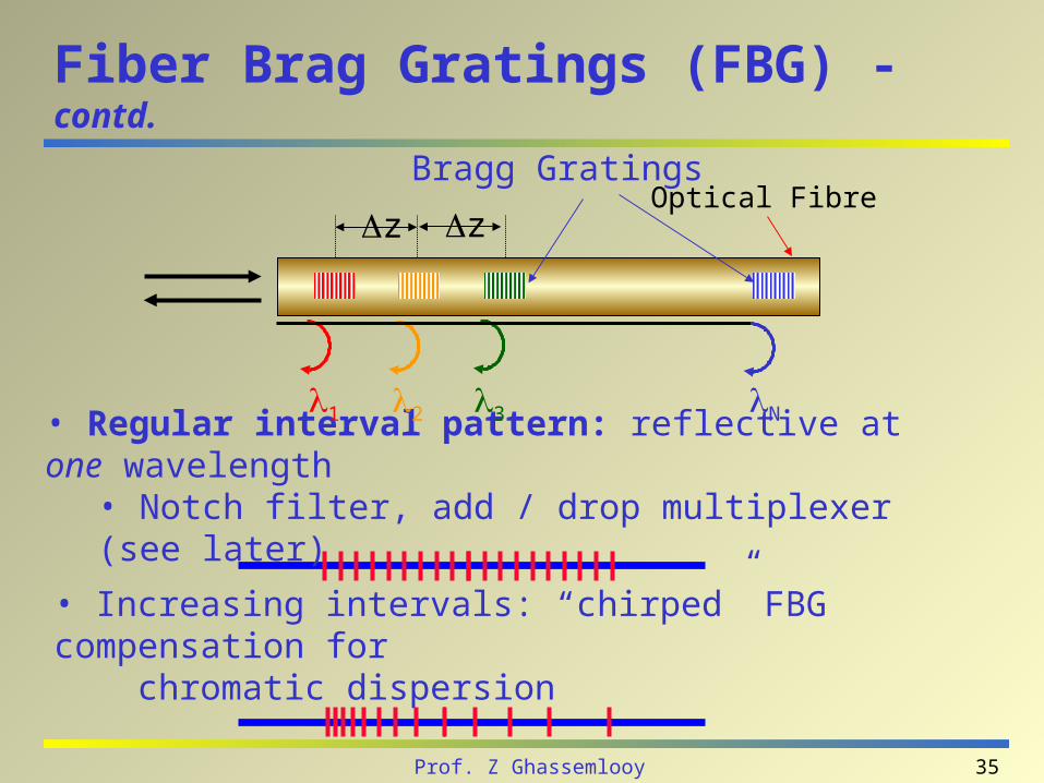
Fiber Brag Gratings (FBG) - contd.
• Increasing intervals: “chirped” FBG compensation for chromatic dispersion
• Regular interval pattern: reflective at one wavelength• Notch filter, add / drop multiplexer (see later)
Optical FibreBragg Gratings
z z
1 2 3 N
36Prof. Z Ghassemlooy
Optical Isolators
Only allows transmission in one direction through it Main application: To protect lasers and optical amplifiers from returning reflected light, which can cause instabilities
Insertion loss:– Low loss (0.2 to 2 dB) in forward direction
– High loss in reverse direction:20 to 40 dB single stage, 40 to 80 dB dual stage)
Return loss:– More than 60 dB without connectors
37Prof. Z Ghassemlooy
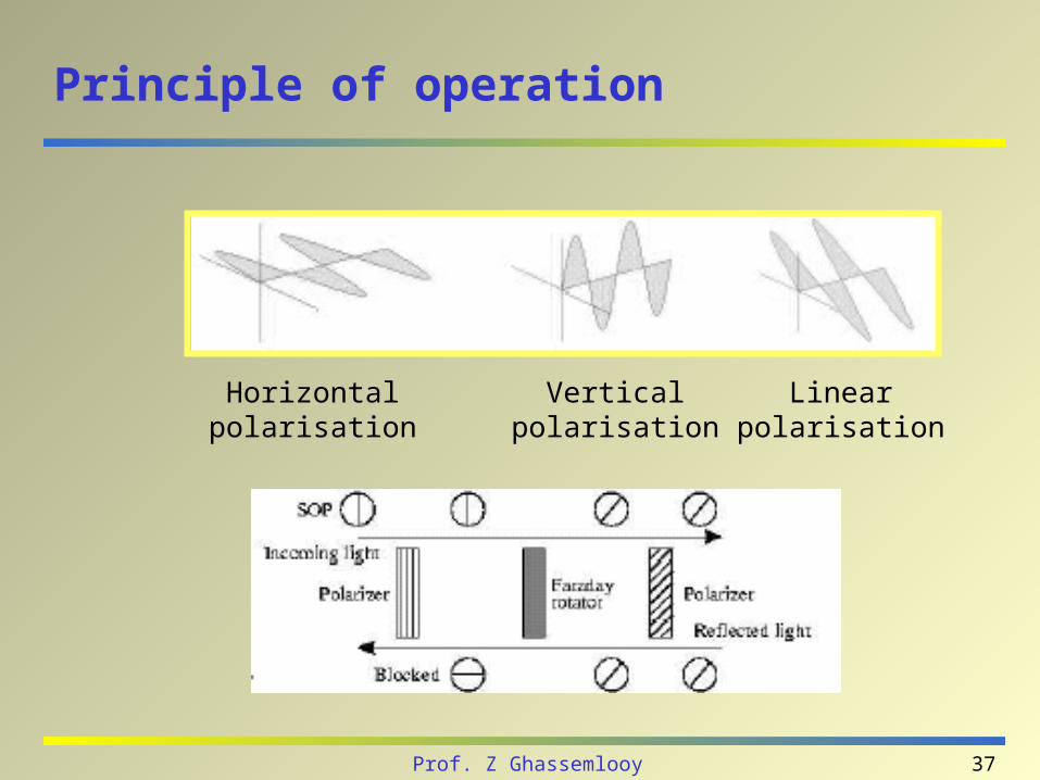
Principle of operation
Horizontalpolarisation
Verticalpolarisation
Linearpolarisation

38Prof. Z Ghassemlooy
Optical Circulators
Based on optical crystal technology similar to isolators– Insertion loss 0.3 to 1.5 dB, isolation 20 to 40 dB
Typical configuration: 3 port device– Port 1 -> Port 2
– Port 2 -> Port 3
– Port 3 -> Port 1
Agilent Tech. LW Div.
39Prof. Z Ghassemlooy
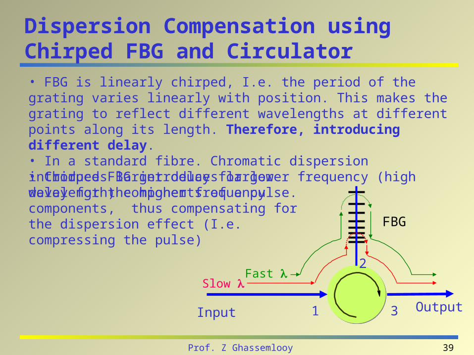
Dispersion Compensation using Chirped FBG and Circulator• FBG is linearly chirped, I.e. the period of the grating varies linearly with position. This makes the grating to reflect different wavelengths at different points along its length. Therefore, introducing different delay.• In a standard fibre. Chromatic dispersion introduces larger delay for lower frequency (high wavelength) components of a pulse.
Fast Slow
Input Output1 3
2
FBG
• Chirped FBG introduces larger delay for the higher frequency components, thus compensating for the dispersion effect (I.e. compressing the pulse)
40Prof. Z Ghassemlooy
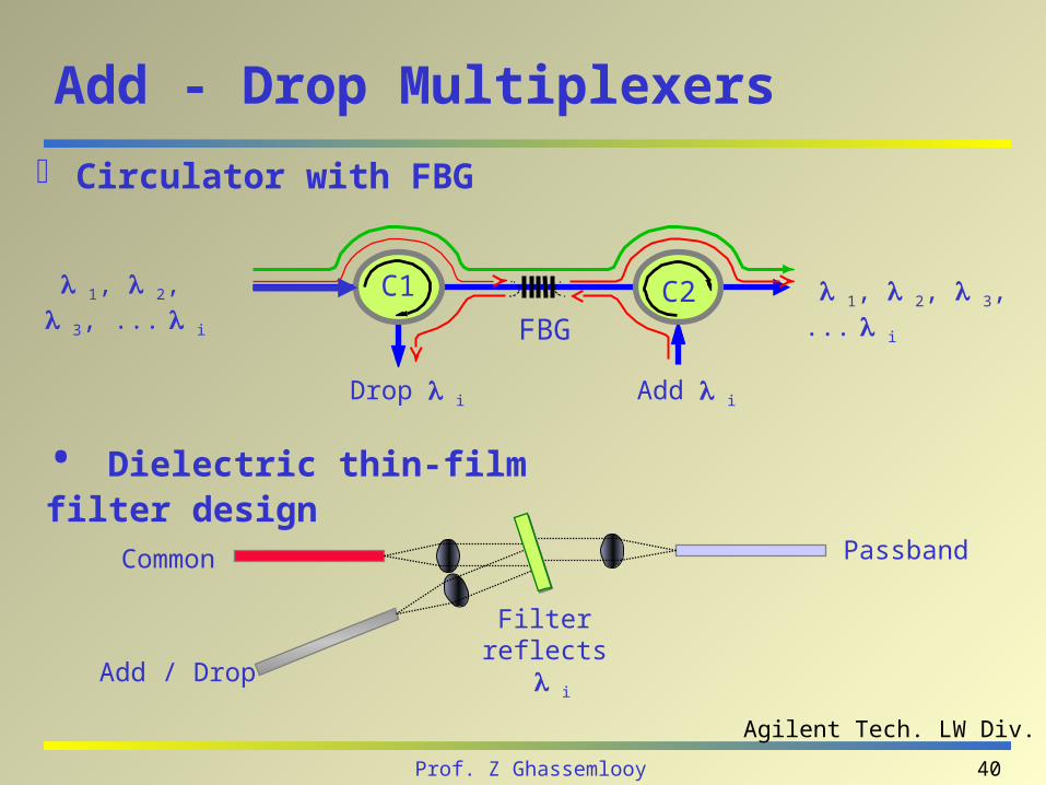
Add - Drop Multiplexers
Circulator with FBG
Add iDrop i
1, 2, 3, ...
i
1, 2, 3, ...
iFBG
C1 C2
• Dielectric thin-film filter design
Filter reflects i
Add / Drop
Common Passband
Agilent Tech. LW Div.
41Prof. Z Ghassemlooy
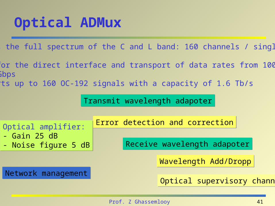
Optical ADMux
Error detection and correctionError detection and correction
Utilizes the full spectrum of the C and L band: 160 channels / single fibre pair Allows for the direct interface and transport of data rates from 100 Mbps to 10 Gbps Transports up to 160 OC-192 signals with a capacity of 1.6 Tb/s
Transmit wavelength adapoterTransmit wavelength adapoter
Receive wavelength adapoterReceive wavelength adapoter
Wavelength Add/DroppWavelength Add/Dropp
Optical supervisory channelOptical supervisory channel
Optical amplifier:- Gain 25 dB- Noise figure 5 dB
Optical amplifier:- Gain 25 dB- Noise figure 5 dB
Network managementNetwork management
42Prof. Z Ghassemlooy
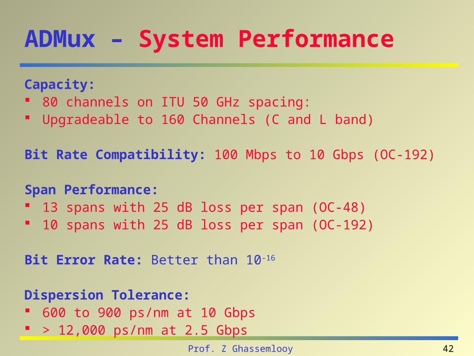
ADMux – System Performance
Capacity: 80 channels on ITU 50 GHz spacing: Upgradeable to 160 Channels (C and L band)
Bit Rate Compatibility: 100 Mbps to 10 Gbps (OC-192)
Span Performance: 13 spans with 25 dB loss per span (OC-48) 10 spans with 25 dB loss per span (OC-192)
Bit Error Rate: Better than 10-16
Dispersion Tolerance: 600 to 900 ps/nm at 10 Gbps > 12,000 ps/nm at 2.5 Gbps

43Prof. Z Ghassemlooy
Multiplexers (MUX) / Demultiplexers (DEMUX)
Key component of wavelength-division multiplexing (WDM) technology
Types of technologies– Cascaded dielectric filters
– Cascaded FBGs
– Phased arrays (see later)
Low crosstalk is essential for demultiplexing
44Prof. Z Ghassemlooy
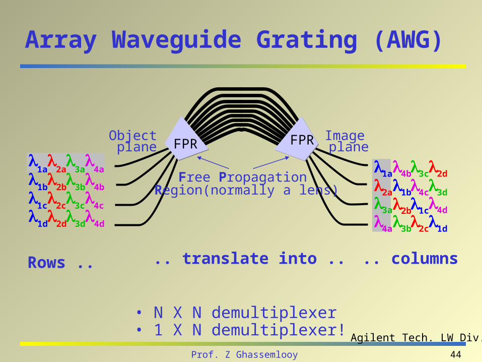
Array Waveguide Grating (AWG)
1a
3a
2a
4a
1b
3b
2b
4b
1c
3c
2c
4c
1d
3d
2d
4d
1a 3c2d4b
1b 3d2a 4c
1c3a2b4d
1d3b2c4a
Rows .. .. translate into .. .. columns
• N X N demultiplexer • 1 X N demultiplexer! Agilent Tech. LW Div.
Object plane
Image planeFPR FPR
Free Propagation Region(normally a lens)
45Prof. Z Ghassemlooy
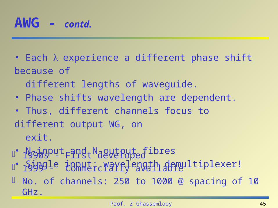
AWG - contd.
1990s - First developed 1999 - Commercially available No. of channels: 250 to 1000 @ spacing of 10 GHz.
• Each experience a different phase shift because of
different lengths of waveguide.• Phase shifts wavelength are dependent.• Thus, different channels focus to different output WG, on
exit.• N-input and N-output fibres • Single input: wavelength demultiplexer!
46Prof. Z Ghassemlooy
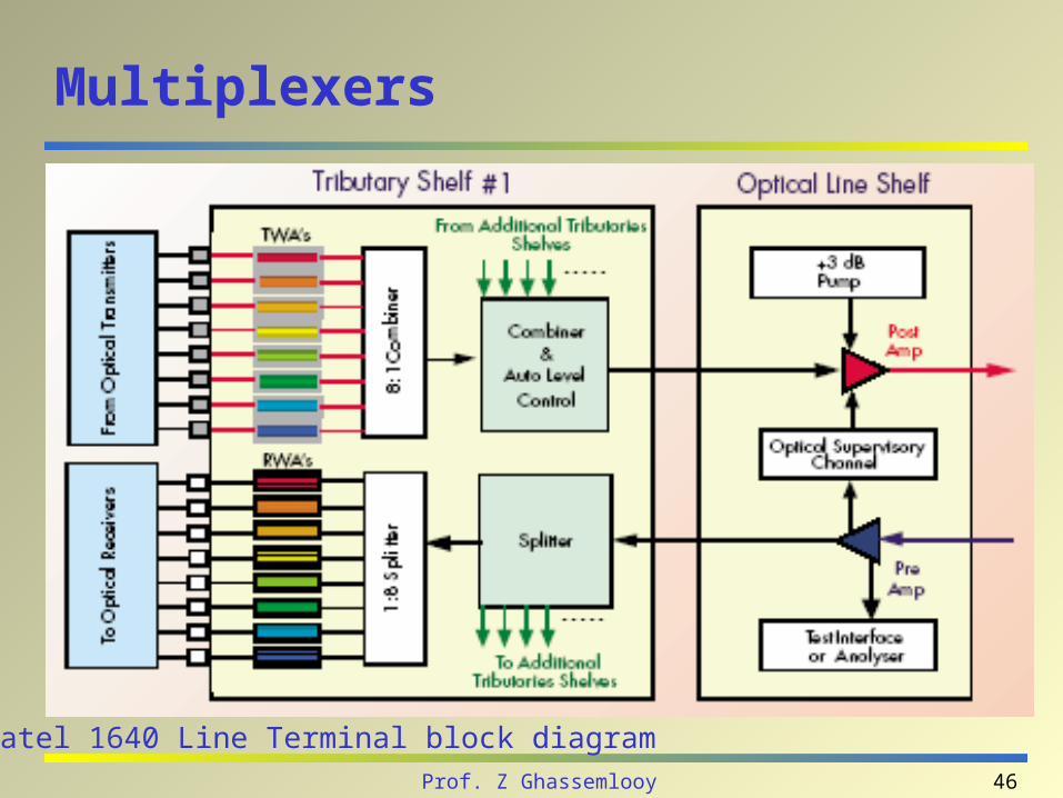
Multiplexers
Alcatel 1640 Line Terminal block diagram

47Prof. Z Ghassemlooy
Multiplexers – Supervisory Channel
This extra channel, at 1510 nm, carries all the management information. It also transports Electrical Order Wire (EOW) data channels, service channels, and control commands for house keeping contacts.
Alcatel 1640 Line Terminal block diagram

48Prof. Z Ghassemlooy
Multiplexers
Transmission lengths of more than 900 km can be achieved on a 0.25 dB/km fibre.
The 240 channels using 3 optical bands:– C (1530–1570 nm)
– L (1570–1610 nm)
– S (1450–1490 nm)
Error detection and correction Different synchronous bit rate Multi bit rae: 2.5 Gbps, 10 Gbps and 40 Gbps Judged by the insertion loss/channel

49Prof. Z Ghassemlooy
MUX - DeMUX - Performance
MUX Judged by the insertion loss/channel
DeMUX Sensitivity to polarisation Crosstalk (< -20 dB)

50Prof. Z Ghassemlooy
References
http://oldsite.vislab.usyd.edu.au/photonics/index.html

51Prof. Z Ghassemlooy
Next Lectures
Optical amplifier Optical Switches