product overview - automated conveyor systems, flexible
TRANSCRIPT

© FlexLink 2022 Stainless steel conveyor systems 7
PO
X70X
X85X
X180X
X300X
WL222X
WL273X
WL374X
WL526X
WL678X
CSX
GRX
FSTX
TR
APX
IDX
Product overviewContentsStainless steel conveyor systems..........................................7Conveyor accessories ...........................................................8Conveyor comparison chart ..................................................8Conveyor component overview .............................................9Technical data – conveyors .................................................11
Chains – configuration strings ............................................15General safety and design considerations ...........................17Maintenance........................................................................19
Stainless steel conveyor systems
Stainless steel conveyor system X70X, X85X, X180X, X300X (68, 83, 175, 295 mm chain)Features Split beams in stainless steel for easy cleaning. High resist-ance to aggressive chemicals. Matching drive units, idlers and guide rail and support components. Standard X180/X300 chains.Series X are stainless steel designs adapted to the require-ments of the food processing, pharmaceutical and hygiene industries. The Series X system is designed for easy inte-gration with aluminium systems.
Examples of application areas
Aerosol cans, liquid soap in plastic bags, soft cheese, detergent powder, tissue paper rolls, food products, per-sonal care products.
Stainless steel conveyor system WL222X, WL273X, WL374X, WL526X, WL678X (152/203/304/456/608 mm belt)
Features
FlexLink's newly developed stainless steel conveyor is designed to fit into demanding primary and secondary packaging applications. It addresses important aspects of today's packing processes, such as being easy to clean, smooth handling of products, safe for operators, robust design, long life, and easy to maintain with a low cost of ownership.The modularized and standardized design ensures fast set up, and facilitates rapid future extensions and changes.
Examples of application areasDry product handling such as bread or frozen products in primary packaging where there is a chance that the pack-age could rupture should also be considered - the conveyor would be an easy to clean alternative to traditional convey-ors.

8 Conveyor accessories © FlexLink 2022
Conveyor accessories
Guide rail components (GRX)Catalogue section Guide rail components deals with var-ious types of guide rails and guide rail support compo-nents. Those products are used with several of the con-veyor systems. A number of pre-designed guide rail structures are shown as examples. New components are available for building automatically adjustable guide rail systems, accommodating products with different widths.
Conveyor support components (CSX)The conveyors are held in place by a well balanced range of support components, with beam support brackets, support beams, feet, etc.
A number of pre-designed support structures are shown as examples.
Conveyor structures built from aluminium beams with standardized T-slots simplify attachment of components and accessories.
Conveyor comparison chart
Simplified end views of conveyor beams, drawn to the same relative scale. Numeric values are widths in mm.
X180175
X300295
XK102
XH103
X85X83
X85Y83
X8583
X6563
XS44
XKP102
200250300
160
X85P83
XT
XT 240
XT 640
XT 480
XT 400
XT 320X4543
43X4543
100
X65P63
X300X295
X180X175X70X
68
HU
HU 480 - 1040
Modular Plastic Belt Conveyor WL Modular Plastic Belt Conveyor WK
WK 150
WK 225
WK 300
WK 600
WK 900
WK 1200
WL526X
WL374X
WL678X
WL 424
WL 322
WL 626
WL273X
WL222X
Modular Plastic Belt Conveyor WLX
Legend
Light grey: Conveyor beams
Dark grey: Pallets or puck
White: Chain/Belt
X70X, X85X, X180X, X300X: WL222X, WL273X, WL374X, WL526X, WL678X
Stainless steel conveyor

© FlexLink 2022 Conveyor component overview 9
PO
X70X
X85X
X180X
X300X
WL222X
WL273X
WL374X
WL526X
WL678X
CSX
GRX
FSTX
TR
APX
IDX
Conveyor component overview
Stainless steel conveyor system X70X, X85X, X180X, X300X – Chains
Stainless steel conveyor system X70X, X85X, X180X, X300X – beams and beam support brackets
Plain chain Friction top chain Conveyor beam Beam support bracket
Stainless steel conveyor system X70X, X85X, X180X, X300X – drive units and idlers
Stainless steel conveyor system X70X, X85X, X180X, X300X – guide rail system
End drive units Idler end unit Guide rail profiles Guide rail brackets
Stainless steel conveyor system X70X, X85X, X180X, X300X – bends Stainless steel conveyor system X70X, X85X, X180X, X300X – support
Wheel bends Plain bends Vertical bends Support components
10 Conveyor component overview © FlexLink 2022
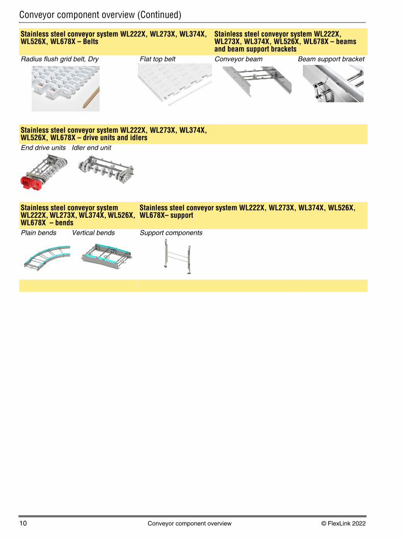
Conveyor component overview (Continued)
Stainless steel conveyor system WL222X, WL273X, WL374X, WL526X, WL678X – Belts
Stainless steel conveyor system WL222X, WL273X, WL374X, WL526X, WL678X – beams and beam support brackets
Radius flush grid belt, Dry Flat top belt Conveyor beam Beam support bracket
Stainless steel conveyor system WL222X, WL273X, WL374X, WL526X, WL678X – drive units and idlersEnd drive units Idler end unit
Stainless steel conveyor system WL222X, WL273X, WL374X, WL526X, WL678X – bends
Stainless steel conveyor system WL222X, WL273X, WL374X, WL526X, WL678X– support
Plain bends Vertical bends Support components

© FlexLink 2022 Technical data – conveyors 11
PO
X70X
X85X
X180X
X300X
WL222X
WL273X
WL374X
WL526X
WL678X
CSX
GRX
FSTX
TR
APX
IDX
Technical data – conveyors
Drive unit capacityThe required motor output power P depends on
• Traction force F
• Chain speed v
The following equation applies:
The maximum permissible traction force of the various drive units, and other useful parameters, are shown in the following tables. Also see diagrams on page 12.
More informationDetailed information about the drive units can be found in “Drive unit guide” and “Spare parts”. See “Technical library” on FlexLink´s website. For information about drive units with variable speed motors, see Drive Unit Guide.
Drive unit specificationsEnd drive unit
TemperaturesWhat temperatures can a FlexLink´s conveyor operate in?
A flex link conveyor can operate in temperatures between –20 °C and +60 °C.
Temperatures up to +100 °C can be taken for short peri-ods. This is mainly for cleaning and rinsing.
What happens if these limits exceed?
In cases where the recommended specifications have not been followed, such as in very warm and cold condi-tions, this will change the properties of the materials used.
FlexLink cannot guarantee components and their func-tionality in case these recommendations are not fol-lowed.
P [W] = 1/60 × F [N] × v [m/min]
X70X X85X X180X/X300X
WLX
Number of teeth on sprocket wheel
H: 16 H: 12 12 2x16
Chain pitch (mm) 25,4 33,5 33,5 25,4
Maximum traction force (N)
Type H_P, HN_P Standard 800 1250 1250
Seechapter
WLX

12 Technical data – conveyors © FlexLink 2022
Technical data – conveyors (continued)
Chain tension limitsTo determine the maximum chain tension allowed, it is necessary to take conveyor speed and conveyor length into consideration. Check diagram 1A and 2B-2E and use the lowest tension value obtained.
Note
The drive unit configurator on the web always proposes a motor strong enough to utilize the maximum permissible chain tension as specified in the diagrams below. Varia-ble speed motors at very low frequencies can sometimes drop below the specified tension. Always check motor data if high pulling force is critical.
Maximum permissible chain tension
Diagram 1A
Tension/length diagram, X70X, X85X, X180X, X300X
Diagram 2A
Tension/speed diagram, X70X, X180X/X300X conveyors
Diagram 2B
Tension/speed diagram, X85X
5 10 15 20 25 30 35 4000
500
1000
1500
2000
m
N
X85X, X180X/X300X
X70X
Tension
Conveyor length
5 10 15 20 25 30 35 40 45 5000
500
1000
1500
2000
m/min
N
X180X/X300X
X70X
60 70 80 90
Tension
Conveyor speed
0
200
400
600
800
1000
1200
1400
10 20 30 40 50 60 80 100
m/min
N
70 90 1100 120
X85X
Tension
Conveyor speed

© FlexLink 2022 Technical data – conveyors 13
PO
X70X
X85X
X180X
X300X
WL222X
WL273X
WL374X
WL526X
WL678X
CSX
GRX
FSTX
TR
APX
IDX
Technical data – conveyors (continued)
Selecting the right chain material
Links
The base link parts of the chain links have the same basic shape, and the same technical properties. Five dif-ferent materials are used. The standard material is acetal resin (POM). Different materials are used.
POM A: Copolymer Acetal with silicon
POM B: Homopolymer Acetal, silicon free
POM C: Copolymer Acetal, silicon free
POM D: Homopolymer with ultra low wear additive
Strength values at 20 °C:
The other materials are not as strong as POM:
• Polyester (PBT): 50% of POM value
• Polyvinylidene fluoride (PVDF): 40% of POM value.
• Conductive POM: 40% of POM value
• High temperature resistant material, 50% of POM value
• Intrinsically static dissipative (ISD) POM: see the fol-lowing table..
Pivots
Most pivots are made in materials as specified in the table below. Otherwise the material is specified next to the link designation.
Chain pitch and weight
The Chain guide lists the weight of most links. To calcu-late chain weight, you need to know the chain pitch (see picture below), the weight of the plastic pivot, the weight of the steel pin, and the cleat separation. See the follow-ing table.
Note
Some of the chains require modification of the drive units. There may also be limitations on minimum bend radius.
Material abbreviations
Chain strength and expansion vs. temperature
Properties Copolymer POM A / C Homopolymer POM B / D
Heat ageing (+) Superior 0
Hot water resistance (+) Superior (-)
Chemical resistance (+) Superior ph 4-14 (-) ph 4-10
Tensile strength 0 (+) Superior
Stifness 0 (+) Superior
Impact Strength 0 (+) Superior
Product (POM) X45 XS; X70X
X65 X85, XH, X180/X300
XK XT, X45H
XT Compact
Maximum working tension
200 N 500 N 1000 N 1250 N 2500 N 900 N 180 N
Product (POM ISD)
X65 X85 XH XT X45H
XT Compact
Maximum working tension
400 N 400 N 550 N 450 N 180 N
Link POM POM (ISD) PBT PVDF
Pivot PA66 PA66 (ISD) PA66 PVDF
ParameterConveyor type
X70X X85X X180X/X300X
Chain pitch, mm 25,4 33,5 33,5
Plastic pivot weight, g 1 2 2
Steel pin weight, g 4 10 10
Material abbreviation Material
POM* Acetal resin
POM* polished Acetal resin, polished surface
POM*, pivot PVDF Acetal resin, pivot: PVDF
POM* GY Acetal resin, grey
POM* BK Acetal resin, black
POM* COND Acetal resin, conductive
POM* ISD NAT Acetal resin ISD, natural colour
POM* ISD GY Acetal resin ISD, grey
PBT Polyester
PVDF Polyvinylidene fluoride
PVDF, pivot PA66 Polyvinylidene fluoride, pivot: PA66
POM* + steel Actetal resin, steel top
POM* + SS Actetal resin, stainless steel top
PA Polyamide
Temperature °C –20 0 20 40 60 80 100 120
Tensile strength factor 1,2 1,1 1,0 0,9 0,8 0,6 0,5 0,3
Linear expansion% –0,4 –0,2 0 0,2 0,5 0,8 1,0 1,3
Pitch

14 Technical data – conveyors © FlexLink 2022
Service factorThe maximum permissible chain tension (see diagrams 1A and 2A-2E on Page 12) depends on the number of conveyor starts and stops per hour. Many conveyors run continuously, whereas others start and stop frequently. It is obvious that frequent starts and stops increase the stress on the chain.
The service factor (see table below) is used to derate for high frequency of starts and stops and for high chain speeds. Divide the tension limit obtained from the graphs by the service factor to get the derated tension limit. A high service factor can be reduced by providing a soft start/stop function.
ImportantThe chain tension calculations are made to ensure that the capacity of the drive unit is sufficient, but not exces-sive, in relation to the strength and friction of the chain. The calculations do not take into account the increased wear resulting from the higher friction in plain bends.
Chain tension calculations
Chain tensionThe tension building up in the chain can be divided into several components:
1 Friction between unloaded chain and slide rails, for example on the underside of the conveyor beam.
2 Friction between loaded chain and slide rails (Figure A).
3 Friction between accumulating products and top sur-face of chain (Figure B).
4 Gravity force acting on products and chain in inclines and verticals (Figure C).
5 Added friction in plain bends. This friction is propor-tional to the chain tension on the low-tension side of the bend. This means that the actual friction depends on the position of the bend in the conveyor (Figure D).
Traction forceThe traction force F required to move the chain depends on the following factors:
Conveyor length........................................... LProduct gravity load per m Transport.................................................... qp Accumulation ............................................. qpaChain gravity load per m.............................. qcFriction coefficient Between chain and slide rail ...................... μr Between chain and products...................... μpBend factor, α° plain bend (hor./vert.).......... kαInclination angle ........................................... β
Operating conditions Service factor
Low to moderate speed or max. 1 start/stop per hour
1,0
Max. 10 starts/stops per hour 1,2
Max. 30 starts/stops per hour 1,4
High speed, heavy load, or more than 30 starts/stops per hour
1,6
L
q +qc p
μr
F
F=L (qc+qp) r⋅ ⋅μ
Figure A
L
q +qc pa
μr
μp F
F=L [(qc+qpa) r+qpa p]⋅ ⋅μ ⋅μ
qpa
Figure B
L
q +qc p
μr
F
F=L (qc+qp) ( r cos +sin )⋅ ⋅ μ ⋅ β β
β
Figure C
F
L
L
FB
α
Figure D

© FlexLink 2022 Chains – configuration strings 15
PO
X70X
X85X
X180X
X300X
WL222X
WL273X
WL374X
WL526X
WL678X
CSX
GRX
FSTX
TR
APX
IDX
Chains – configuration strings
Below, example of text strings obtained from the configu-rator with explanations.
InputPlatform: “X85”
Chain type: “XBTF 5A85 U”
CC distance (mm) [133..167]: “167 “ (depending on the PAR value, the CC distance will change.)
PAR 1-20: “5” (depending on the CC distance, the PAR value will change.)
Total desired length (m): “26”
OutputChain pitch: “33,5” (see table below)
Actual CC distance (mm): The selected CC distance will be round off to the closest value which matches the chain pitch. E.g. for value 400, PlatformX85 (pitch 33,5 mm), CC dis-tance= 400 mm, the Actual CC will be 402 mm.
Actual chain length (mm): The actual length depending on the CC/PAR value and that the chain always ends with a cleated link. This causes the length to vary from 3000-3250 mm or 5000 to 5500 mm depending on selected platform.
Total chain needed (mm): “26 052” (All configurable chains starts with a number of plain links in this case 4 links before the cleat link (PAR5). The desired length is 26 000 mm and the chain pitch for X85 is 33,5 mm. This creates an incorrect number of plain links before the last cleat link. The length is corrected by adding plain links (according to the desired PAR value) and a cleated link after the “last” cleat link. See picture.
Qty to be delivered: “6” (The desired length is 26 m and items will be delivered in multiples of 5 -meter lengths; to cover demand of necessary length, 6 packages of chains are needed.
Configuration result:
ParameterConveyor type
X70X, XS, X45H, X65, XT
X85 XH XK X180/X300
Chain pitch, mm 25,4 33,5 35,5 38,1 33,5
Input
Output
Pitch
Item no Qty Description
XBTF 5A85 U 6 XBTF 5A85 U PAR5
PAR5 (4 plain links+1 cleated)
Pitch (33,5)
Total desired length 26000 mm
Total chain needed (mm) 26052 mm
+

16 Chains – configuration strings © FlexLink 2022
Bend factorsEach plain bend introduces a bend factor kα. This factor is defined as the ratio between chain tension measured just after the bend and that measured before the bend. The bend factor depends on
• the amount of direction change of the bend (angle α)
• the coefficient of friction, μr, for the friction between chain and slide rails.
When the conveyor is dry and clean, the friction coeffi-cient, μr, will be close to 0,1.
The bend factor must be used since the frictional force of a plain bend depends not only on the chain and prod-uct weight and the coefficient of friction, but also on the actual tension of the chain through the bend. This tension causes additional pressure to the conveyor beam and slide rail from the chain. The additional force is directed towards the centre of the bend.
Calculation of this additional force is more compli-cated, since the chain tension varies through the con-veyor, being maximum at the “pull” side of the drive unit, and virtually zero at the inlet of the return chain. The bend factor provides a means of including the added fric-tion in bends into the calculations.
The same bend factors apply to horizontal and verti-cal plain bends. See the table.
Note
Plain bends should only be used in exceptional cases. For normal applications, use wheel bends.
Bend type (Vertical or Plain bend)
30° 45° 60° 90°
Bend factor kα 1,2 1,3 1,4 1,6

© FlexLink 2022 General safety and design considerations 17
PO
X70X
X85X
X180X
X300X
WL222X
WL273X
WL374X
WL526X
WL678X
CSX
GRX
FSTX
TR
APX
IDX
General safety and design considerations
Introduction
Critical factorTo achieve an operational installation which is reasonably safe for all people involved in its use and maintenance, it is necessary to consider certain aspects. This is done when designing a conveyor system. The chain is generally the critical factor to consider with guarding.
SafeguardingAll pinch and shear points as well as other exposed mov-ing parts that present a hazard to people at their worksta-tions or their passageways must be safeguarded. Overhead conveyors must be guarded to prevent objects falling. Cleated conveyor chains are more hazardous in creating more pinch and shear points than plain conveyor chains.
Safeguarding can be achieved by:
• Location
Location of the hazardous area away from the area occupied by personnel, wherever possible.
• Guards
Mechanical barriers preventing entry into the hazard-ous areas or protecting against falling objects.
• Control devices
Machine controls which prevent the interruption of hazardous operations/conditions.
• Warnings
Instructions, warning labels, or sound/light signals which alert to hazardous conditions.
Safeguarding should be designed to minimize discomfort or difficulties to the operator. Bypassing or overriding the safeguarding during operation should be difficult.
Warning labels etc. should only be used when all other means of safeguarding will impair the function of the installation or are not cost effective.
The degree of safeguarding required should be iden-tified during the implementation of the essential safety requirement during the design process.
Special considerationsWhen correctly applied, FlexLink family of components are safe to use and maintain. It is however necessary for those responsible for design, installation, operation and maintenance of installations to be aware of certain areas where special attention is required.

18 General safety and design considerations © FlexLink 2022
Note
The slip clutch is not a personnel safety device, but a device to protect the conveyor equipment.
End drive units
• The chain slack (catenary) of the end drive units must be maintained during the system lifetime.
• If side plates are fitted, the chain must be shortened if the chain becomes visible below the level of the side plates.
• The opening between the links when they turn round the end roller could be a risk. Drive ends should not be accessible during conveyor operation wherever possible.
For coupled drive units, safety protection should be applied to the connecting shaft.
Idler units
• The opening between the links when they turn round the idler roller could be a risk. Idler ends should not be accessible during conveyor operation wherever possi-ble.
Wheel bends
• Guarding may be required at wheel bends depending upon location of bends and load applied to the con-veyor.
Cleated chains
• Any application incorporating cleated chains requires careful safety consideration. Pinch and shear points are generated throughout the assembly of the incor-porated components. Therefore generous guarding should always be employed to fully protect within user operating limitations.
• There is a higher risk of product damage when using cleated chains. Special attention must be given to operator access in the event of products becoming trapped or similar.
Maintenance
The maintenance routine of FlexLink´s conveyors should also include procedures to ensure that the guarding remains securely fastened and effective (if not inter-locked via control system etc.).
FlexLink´s components are continuously reviewed to improve performance either by design modification or material upgrade. In all these reviews user safety is our primary consideration.
All associated technical data are retained at the man-ufacturers address.
Control system
Before operating or completing any maintenance on con-trol system, read the associated section as supplied with the equipment documentation.
If there are any questions as to the safe operating pro-cedures of the equipment supplied, please contact Flex-Link immediately.

© FlexLink 2022 Maintenance 19
PO
X70X
X85X
X180X
X300X
WL222X
WL273X
WL374X
WL526X
WL678X
CSX
GRX
FSTX
TR
APX
IDX
Maintenance
System maintenance
Introduction
The following section is designed to offer assistance for your planned maintenance schedule. It may become evi-dent that the suggested maintenance intervals can be extended to accommodate your local environmental con-ditions.
Maintenance of the conveyor systems should only be carried out by competent persons, who are familiar with FlexLink´s equipment. If there is any doubt as to the most suitable procedure for maintenance, consult your Flex-Link supplier.
Run-in periodTwo to three weeks are usually enough as a run-in period. During this time, the conveyor should be cleaned a couple of times, to remove dust. After run-in, wear will be minimal, unless particles from the product or process reach the conveyor continuously.
Chain elongationEspecially during the run-in period, and if the load is heavy, the conveyor chain will slowly increase in length. This effect will be most obvious for long conveyors. After continuous operation for two weeks, it is often possible to remove a couple of chain links. After this period, we rec-ommend a check every 3–6 months.
Non FlexLink equipment
Equipment and components which are not from the Flex-Link family of products should be maintained and ser-viced in accordance with their respective manufacturer’s instructions.
Safety considerations
Before starting any maintenance on your FlexLink equip-ment, the following safety instructions must be observed:
• All electricity must be switched off.
• Make sure that the motor switch is also switched off and locked in the “off” position.
• Pneumatic and/or hydraulic power must be discon-nected and any pressure accumulation released.
• Products being transported should, if possible, be removed from the conveyor chain.
• Staff affected must be informed that maintenance work is being undertaken.
Warning
Do not climb onto the equipment.

20 Maintenance © FlexLink 2022